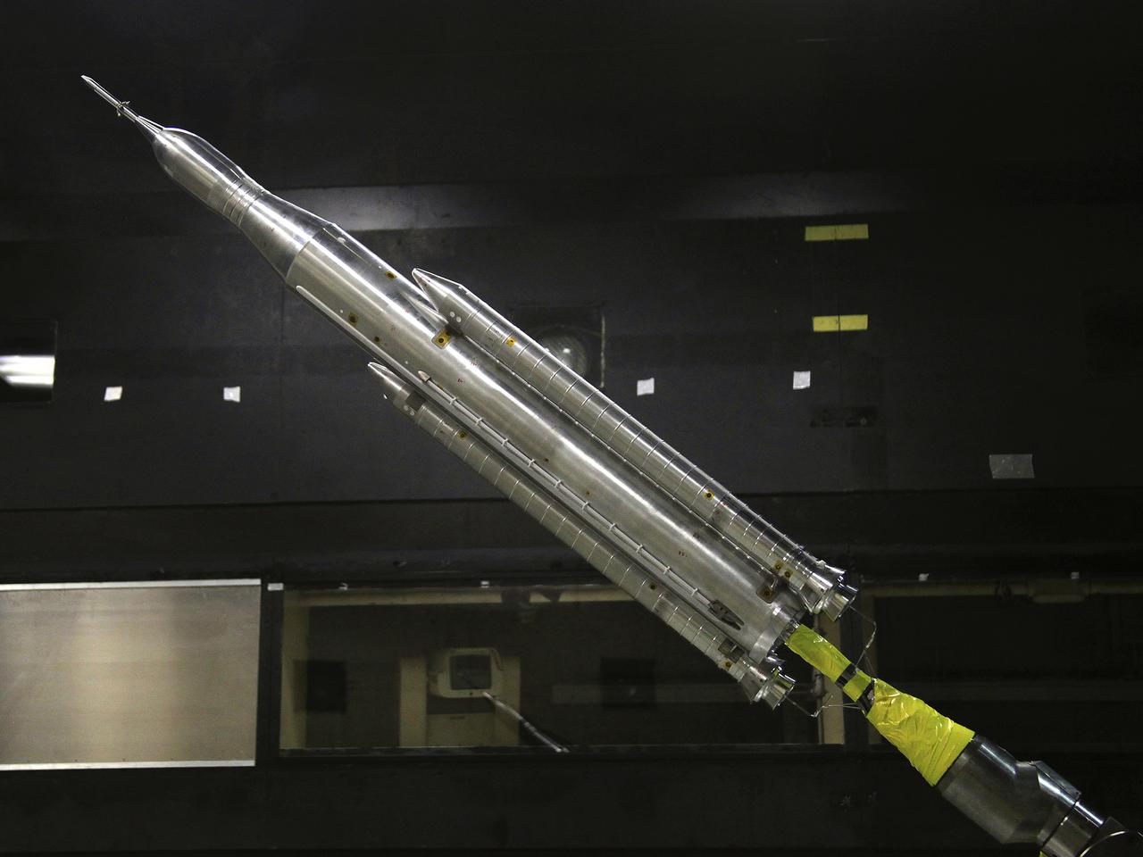
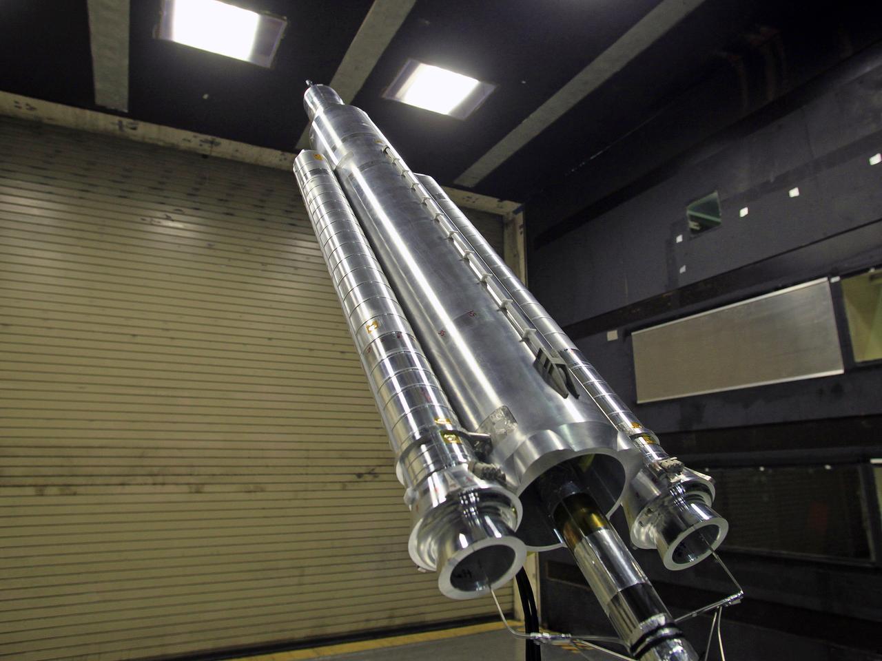
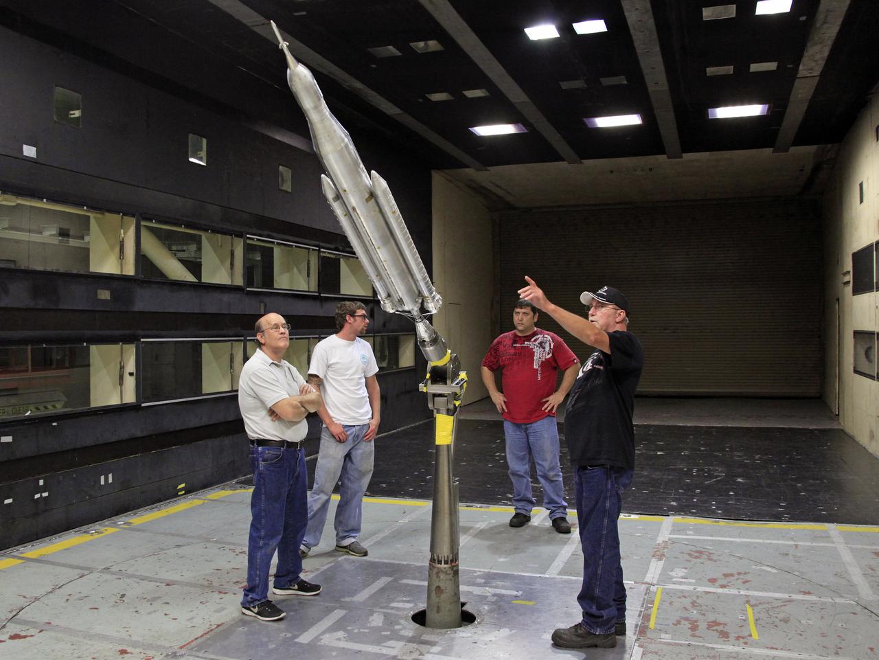
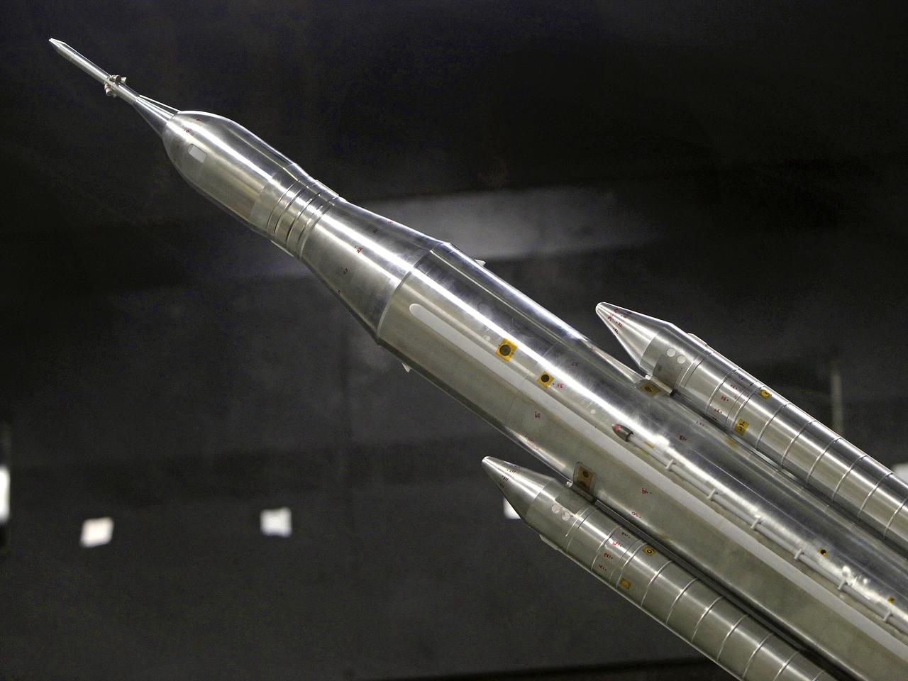
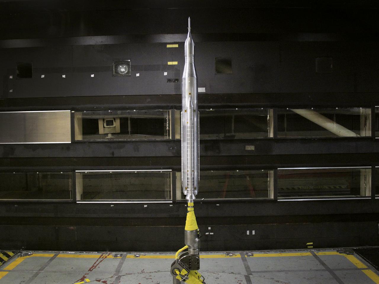
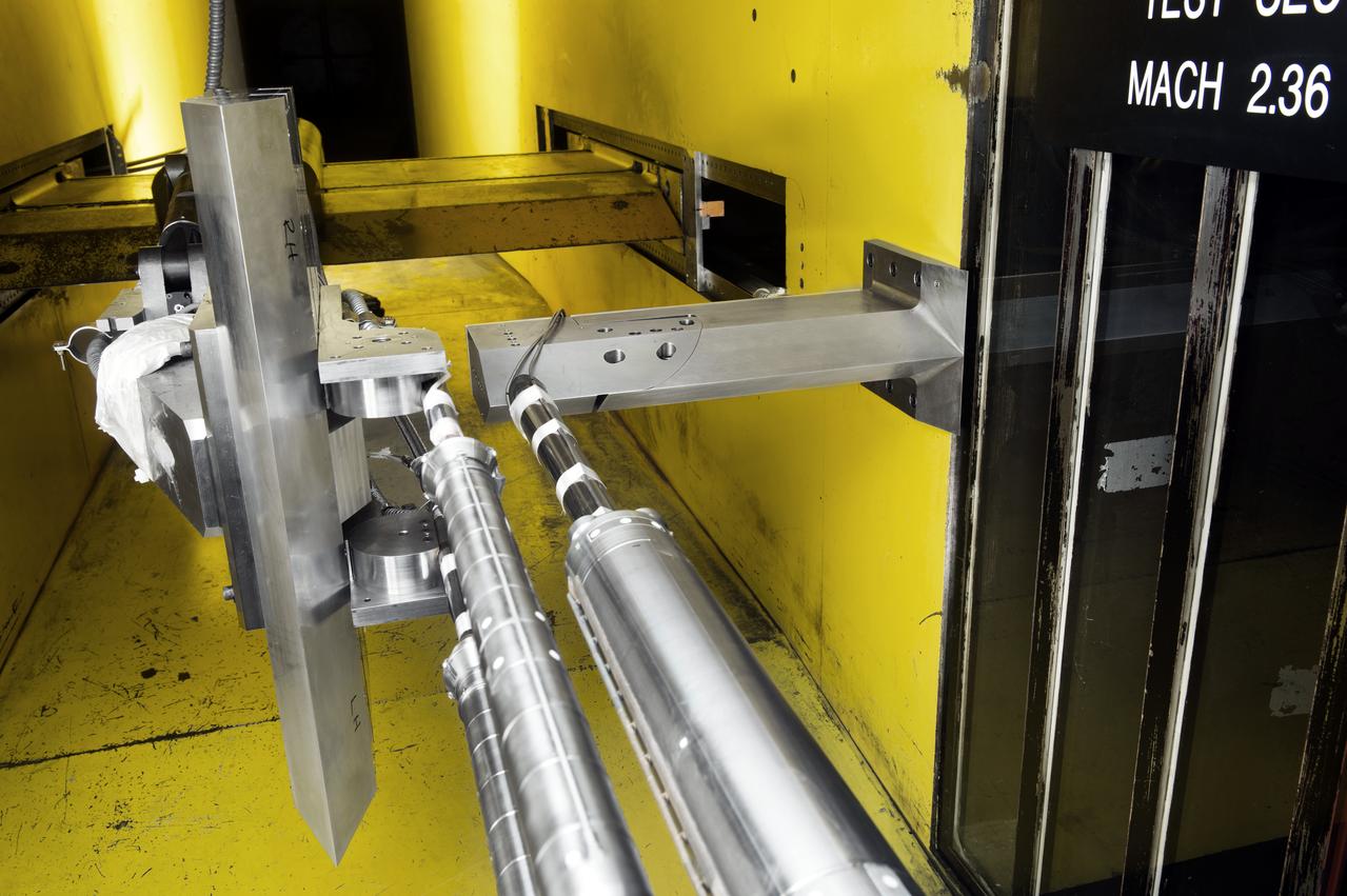
The model of the Space Launch System for the Orion Space Capsule is being prepared for windtunnel test in the 14x22 Subsonic windtunnel at NASA Langley.
The model of the Space Launch System for the Orion Space Capsule is being prepared for windtunnel test in the 14x22 Subsonic windtunnel at NASA Langley.
The model of the Space Launch System for the Orion Space Capsule is being prepared for windtunnel test in the 14x22 Subsonic windtunnel at NASA Langley.
The model of the Space Launch System for the Orion Space Capsule is being prepared for windtunnel test in the 14x22 Subsonic windtunnel at NASA Langley.
The model of the Space Launch System for the Orion Space Capsule is being prepared for windtunnel test in the 14x22 Subsonic windtunnel at NASA Langley.
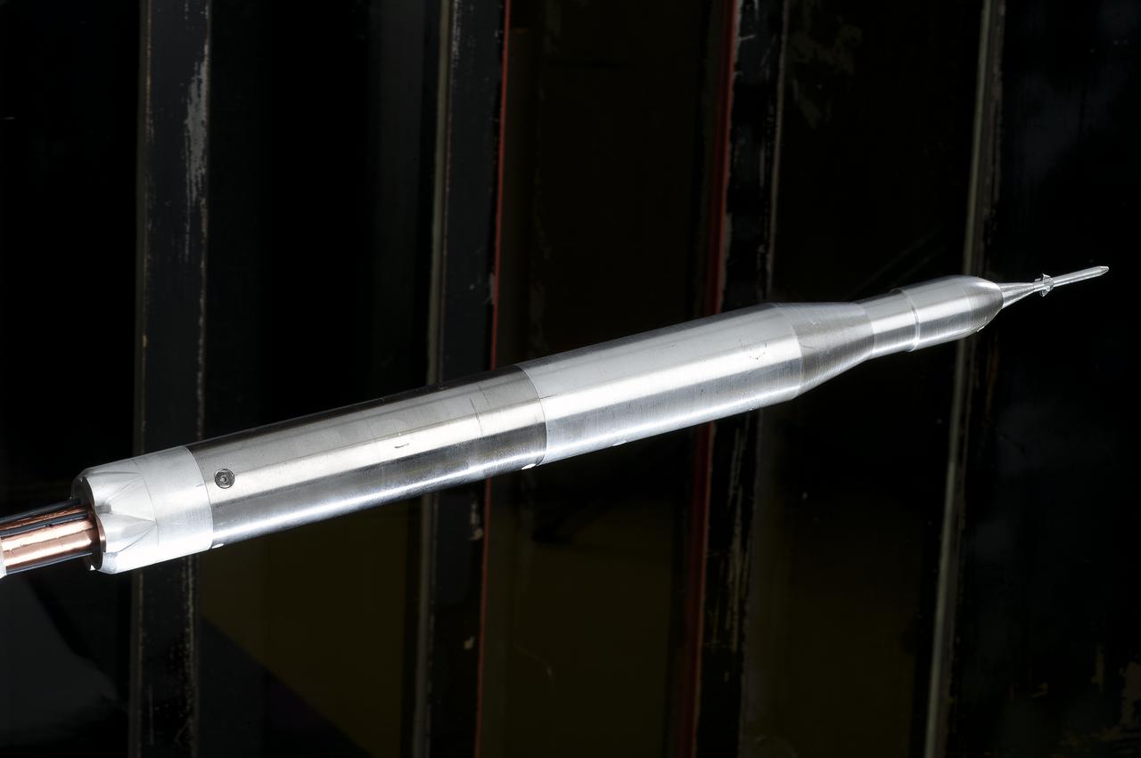
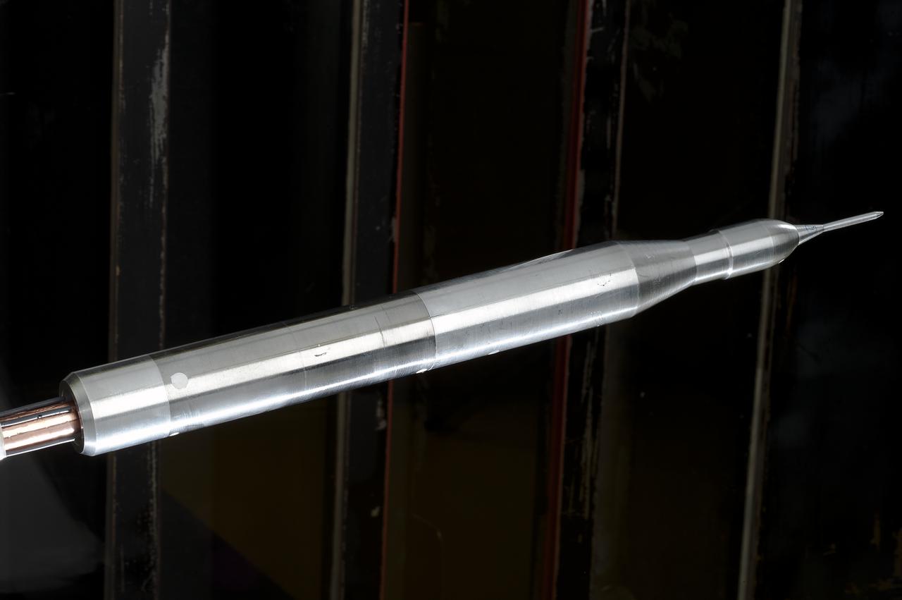
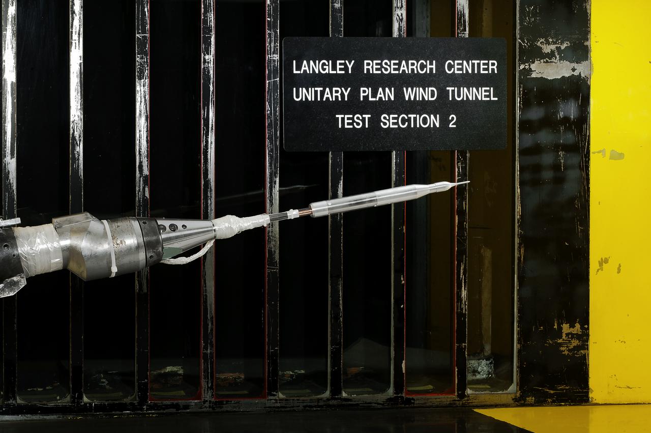
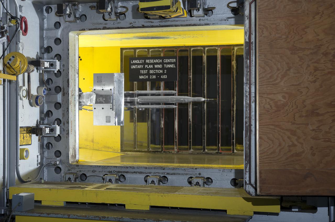
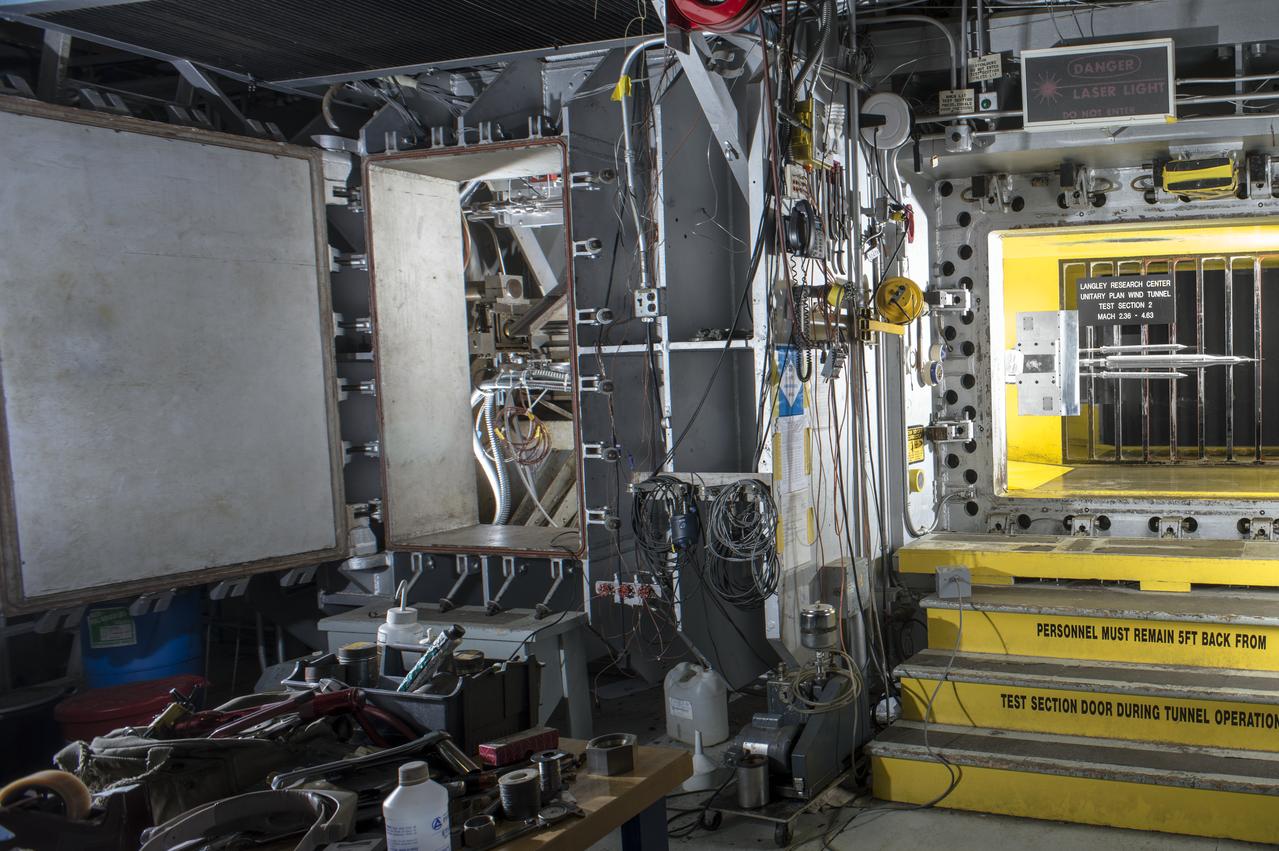
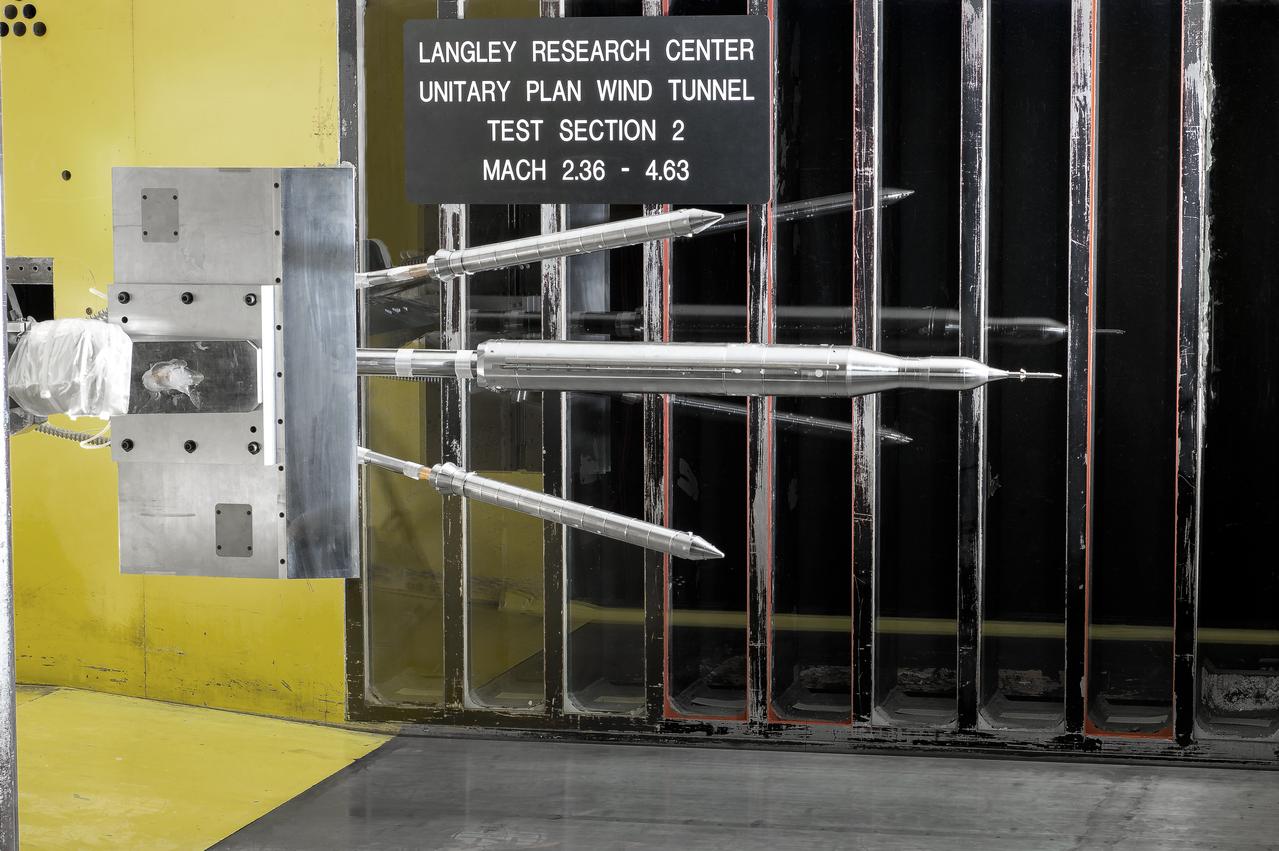
0.4% Scale (SLS) Space Launch System Model Test In NASA LaRC Unitary Plan Wind Tunnel
0.4% Scale (SLS) Space Launch System Model Test In NASA LaRC Unitary Plan Wind Tunnel
0.4% Scale (SLS) Space Launch System Model Test In NASA LaRC Unitary Plan Wind Tunnel
0.4% Scale (SLS) Space Launch System Model Test In NASA LaRC Unitary Plan Wind Tunnel
0.4% Scale (SLS) Space Launch System Model Test In NASA LaRC Unitary Plan Wind Tunnel
0.4% Scale (SLS) Space Launch System Model Test In NASA LaRC Unitary Plan Wind Tunnel
Dr. Ruth Jones, Branch Chief for Industrial Safety Branch (QD12) at MSFC, poses with model of Space Launch System, in Building 4220. Photo for publication in University of Arkansas, Pine Bluff, Alumni magazine.
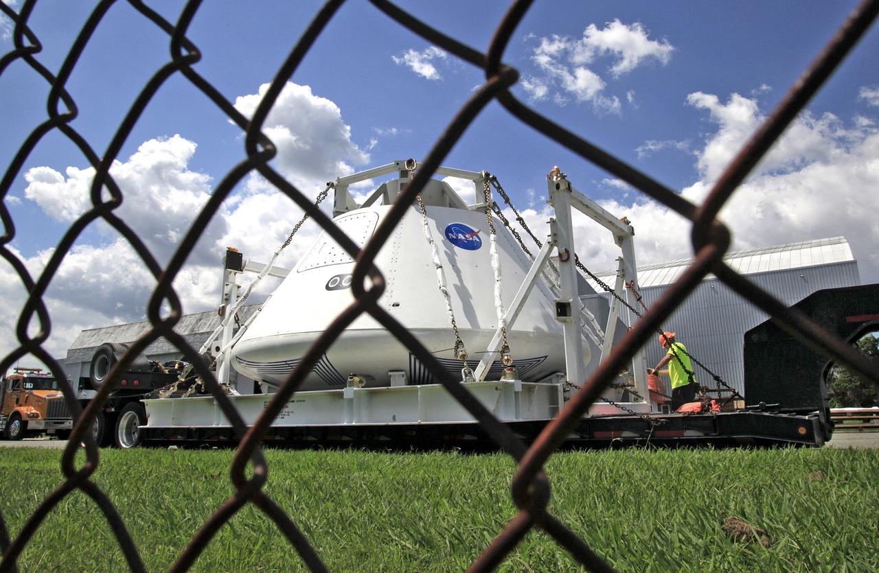
Orion Test Capsule loaded on a flatbed trailer at NASA Langley to be transport to Fort Eustis, VA. where it will be transported by barge to Norfolk Va. for open water recovery test.
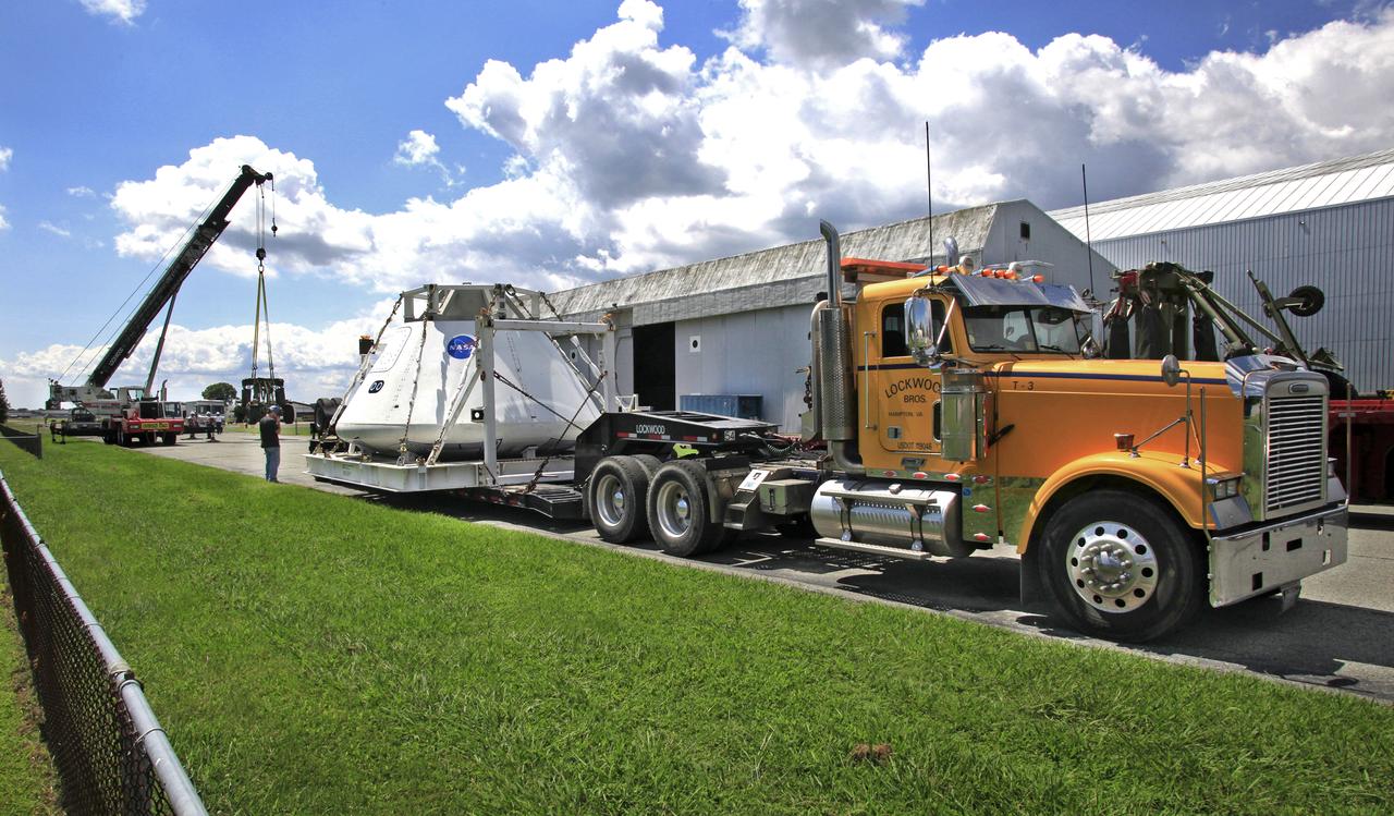
Orion Test Capsule loaded on a flatbed trailer at NASA Langley to be transport to Fort Eustis, VA. where it will be transported by barge to Norfolk Va. for open water recovery test.
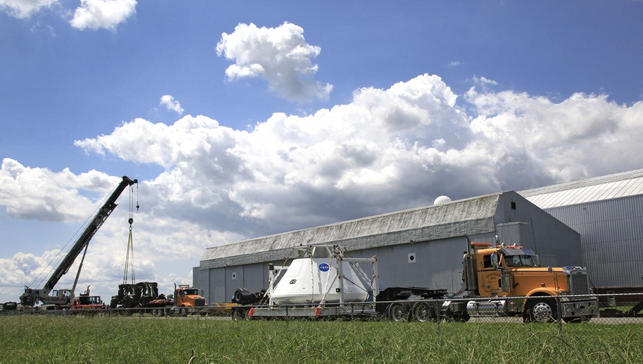
Orion Test Capsule loaded on a flatbed trailer at NASA Langley to be transport to Fort Eustis, VA. where it will be transported by barge to Norfolk Va. for open water recovery test.
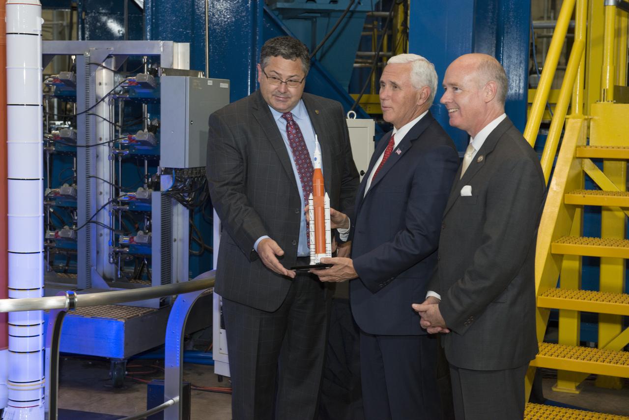
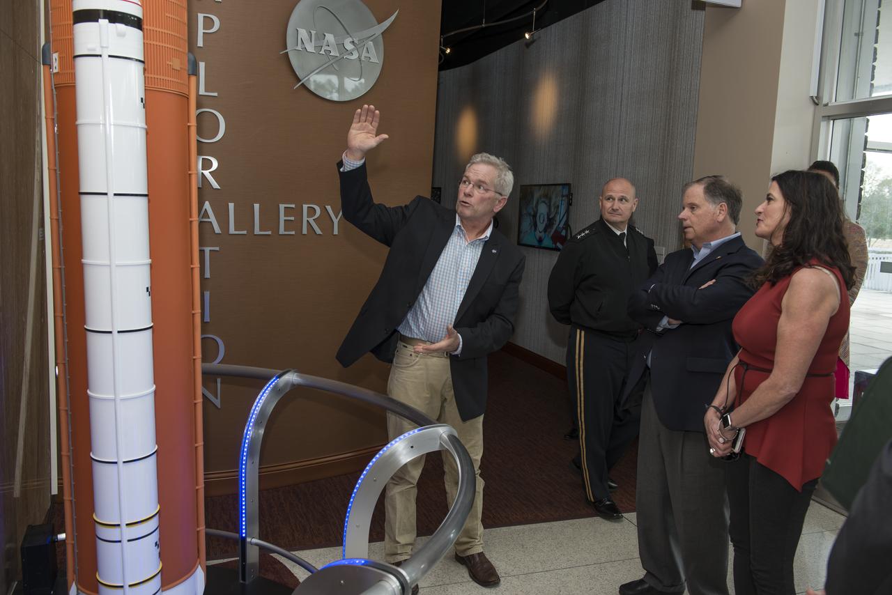
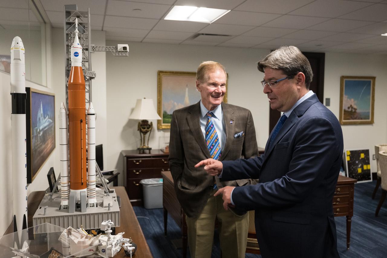
Marshall Space Flight Center Director Todd May (left) presents Vice President Mike Pence (center) with a Space Launch System model. May, Vice President Pence, and Congressman Robert Aderholt (R-AL) (right) are standing in front of an SLS test stand where the engine section, the bottom section of the 212-foot-tall core stage, is being tested. Earlier, engineers working on the test gave the Vice President a close up look at test hardware. The test hardware is for the SLS core stage engine section, which is the bottom of the core stage where the four RS-25 engines are housed. The engine section structure must withstand the incredible stresses produced by more than 8 million pounds of thrust during launch and ascent.
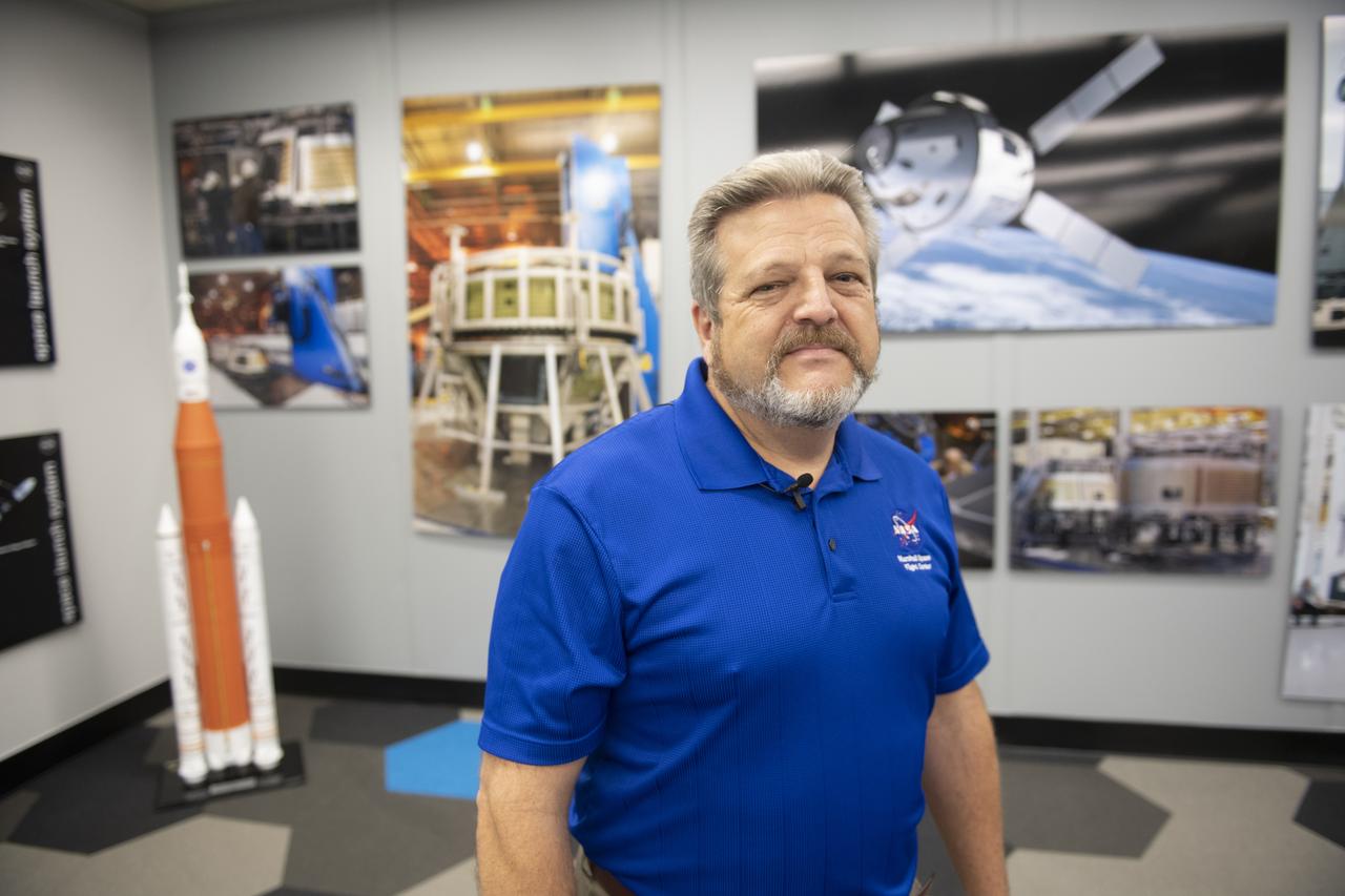
MAF Director Robert Champion stands within the Michoud Assembly Facility model room to showcase the Artemis program, Space Launch System (SLS) hardware, and facility resources of America’s Rocket Factory.
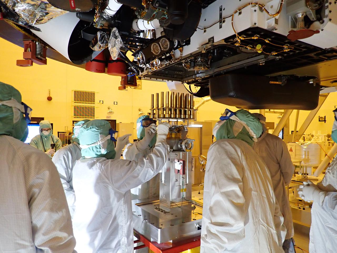
Inside the Payload Hazardous Servicing Facility at NASA’s Kennedy Space Center in Florida, workers prepare to install the Sample Caching System Sterile Flight Model hardware on the Mars Perseverance rover on May 21, 2020. The system includes 39 sample tubes that will be inserted into the underside of the rover. Each tube is sheathed in a gold-colored cylindrical enclosure to protect it from contamination. Perseverance rover will carry 43 sample tubes in total to Mars' Jezero Crater. The Mars Perseverance rover is scheduled to launch in mid-July atop a United Launch Alliance Atlas V 541 rocket from Pad 41 at nearby Cape Canaveral Air Force Station. The rover is part of NASA’s Mars Exploration Program, a long-term effort of robotic exploration of the Red Planet. The rover will search for habitable conditions in the ancient past and signs of past microbial life on Mars. The Launch Services Program at Kennedy is responsible for launch management.
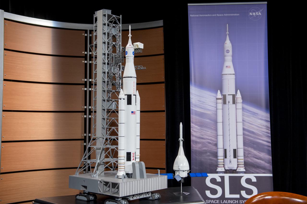
Models of the Space Launch System and Orion spacecraft are displayed during a panel discussion on deep space eploration at the Newseum on Tuesday, November 12, 2013 in Washington. Photo Credit: (NASA/Jay Westcott)
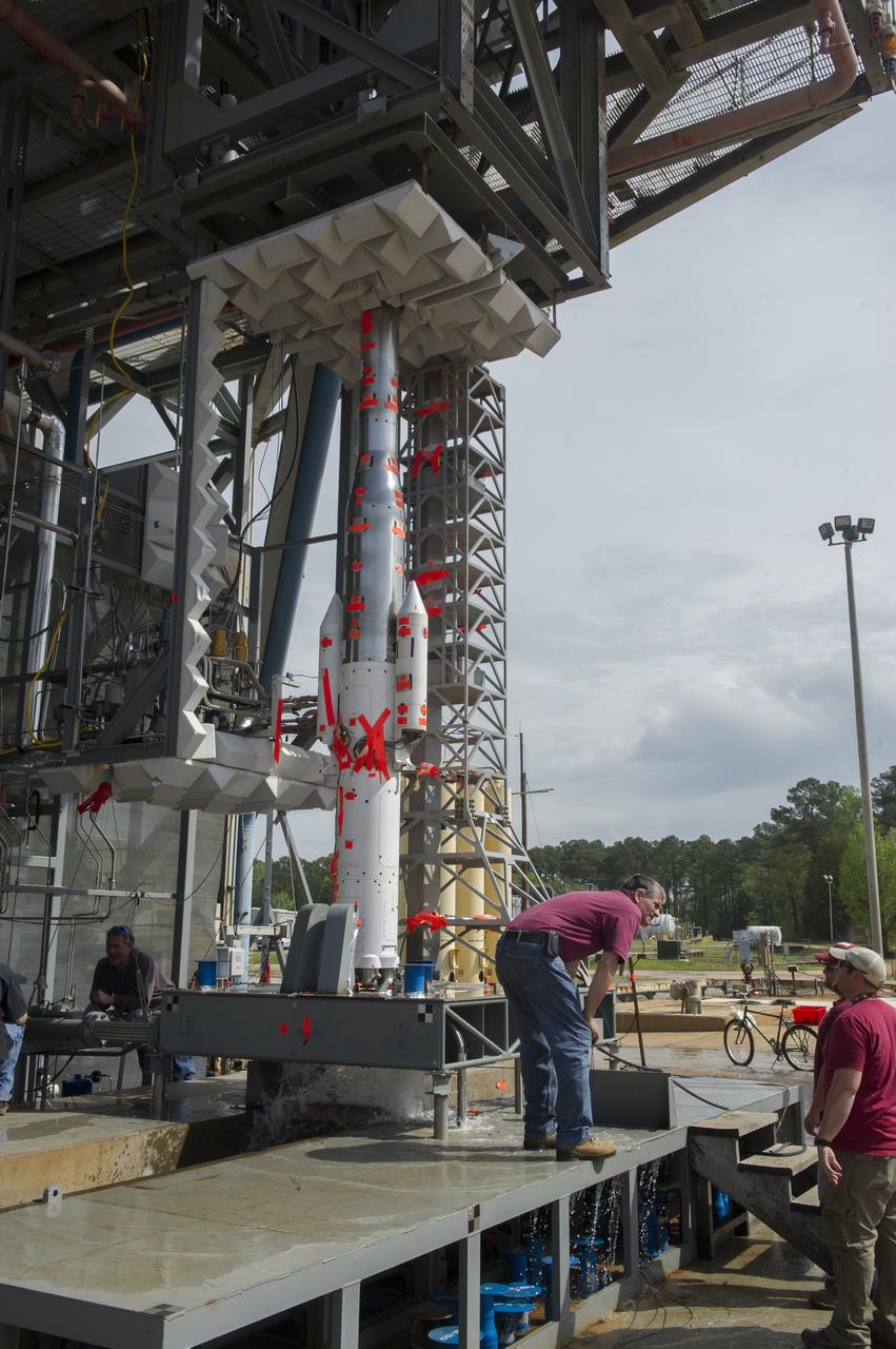
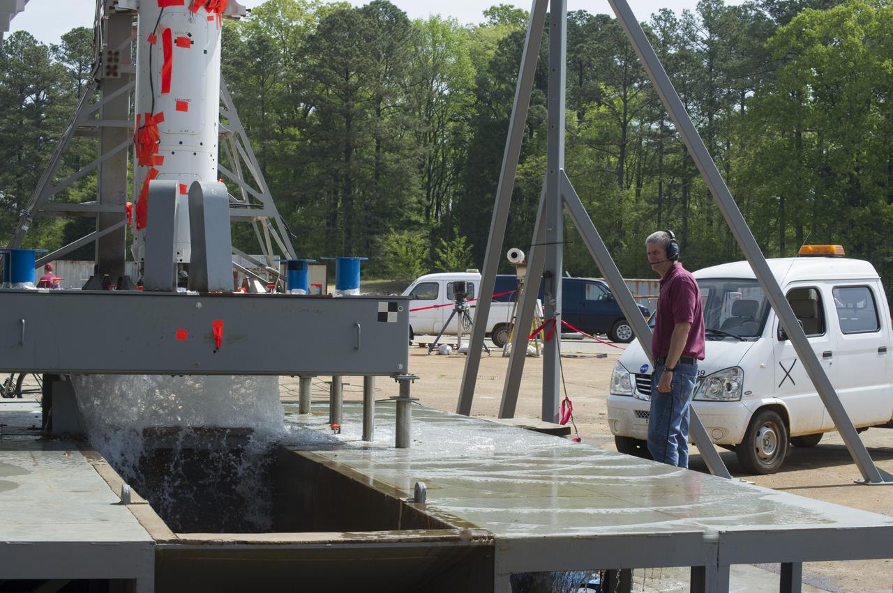
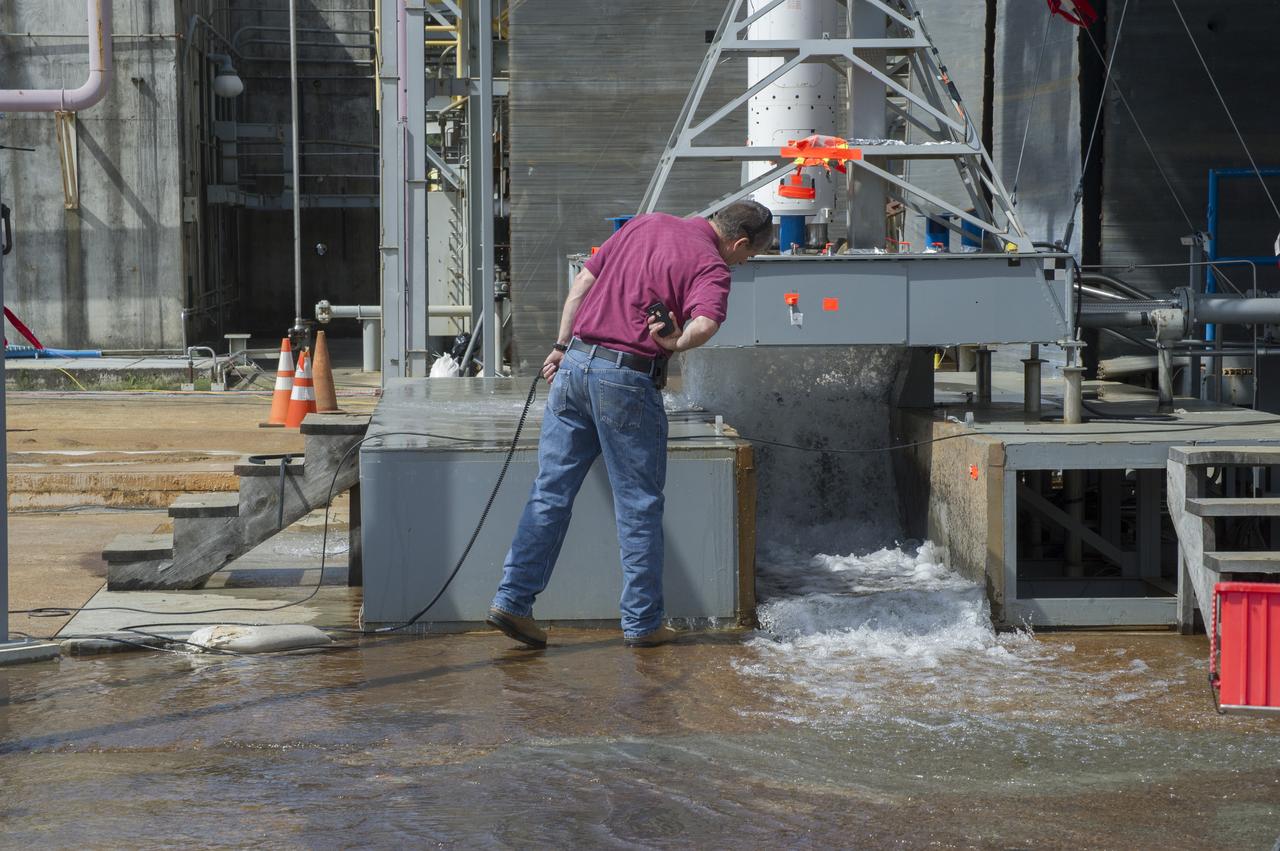
TEST ENGINEER DENNIS STRICKLAND CONDUCTS WATER FLOW TESTS AT TEST STAND 116 FOR SPACE LAUNCH SYSTEM SCALE MODEL ACOUSTIC TEST SERIES (WITH SOLID ROCKET BOOSTERS)
TEST ENGINEER DENNIS STRICKLAND CONDUCTS WATER FLOW TESTS AT TEST STAND 116 FOR SPACE LAUNCH SYSTEM SCALE MODEL ACOUSTIC TEST SERIES (WITH SOLID ROCKET BOOSTERS)
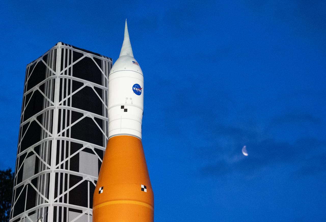
An inflatable model of the Space Launch System (SLS) is seen at sunrise ahead of the White House Easter Egg Roll, Monday, April 21, 2025, on the South Lawn of the White House in Washington. Photo Credit: (NASA/Keegan Barber)
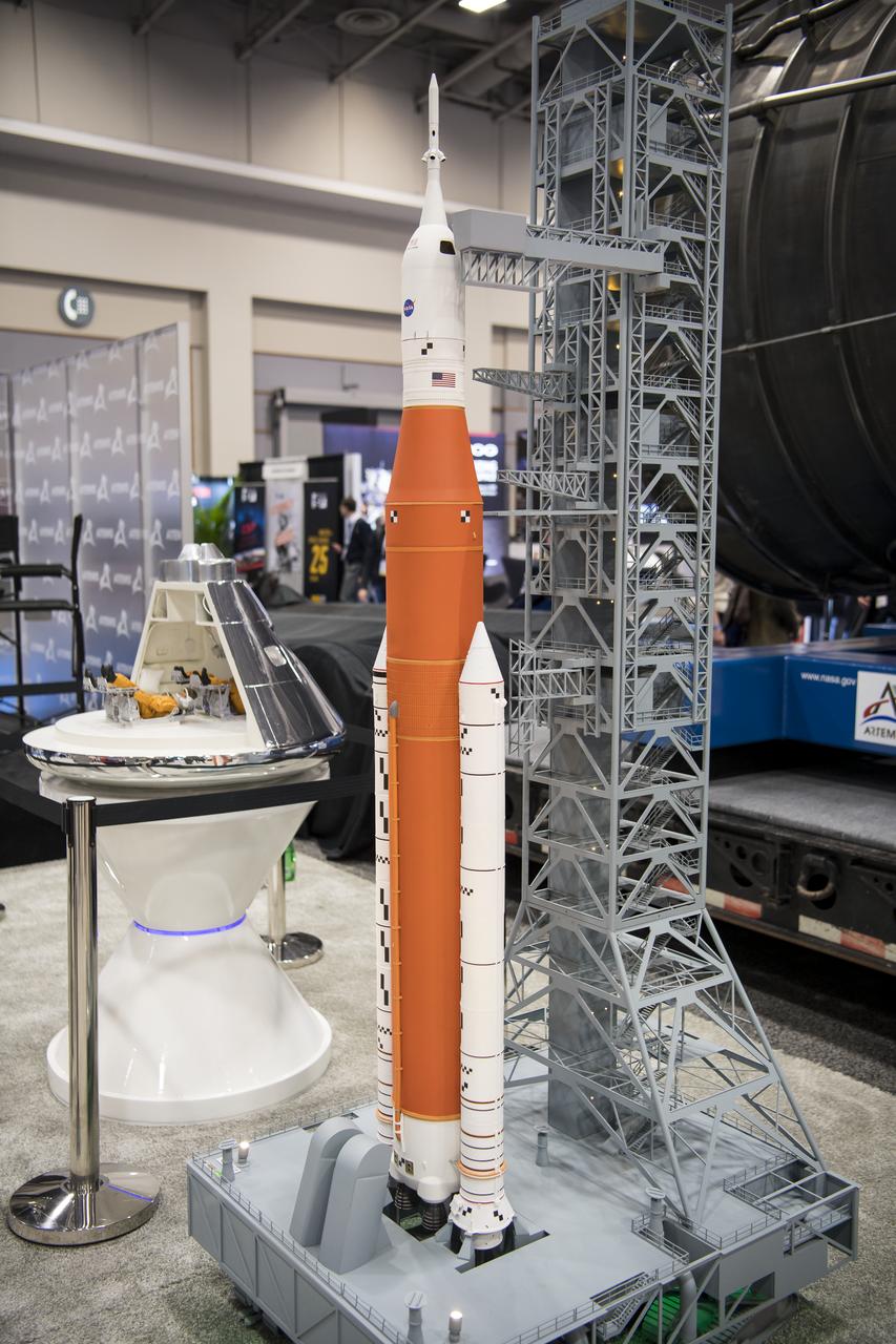
A model of is the Space Launch System (SLS) is seen at the NASA exhibit during the 70th International Astronautical Congress, Friday, Oct. 25, 2019, at the Walter E. Washington Convention Center in Washington. Photo credit: (NASA/Aubrey Gemignani)

An inflatable model of the Space Launch System (SLS) is seen during a reception with Artemis II crew members Wednesday, June 5, 2024, at the Dirksen Senate Office Building in Washington. Photo Credit: (NASA/Keegan Barber)
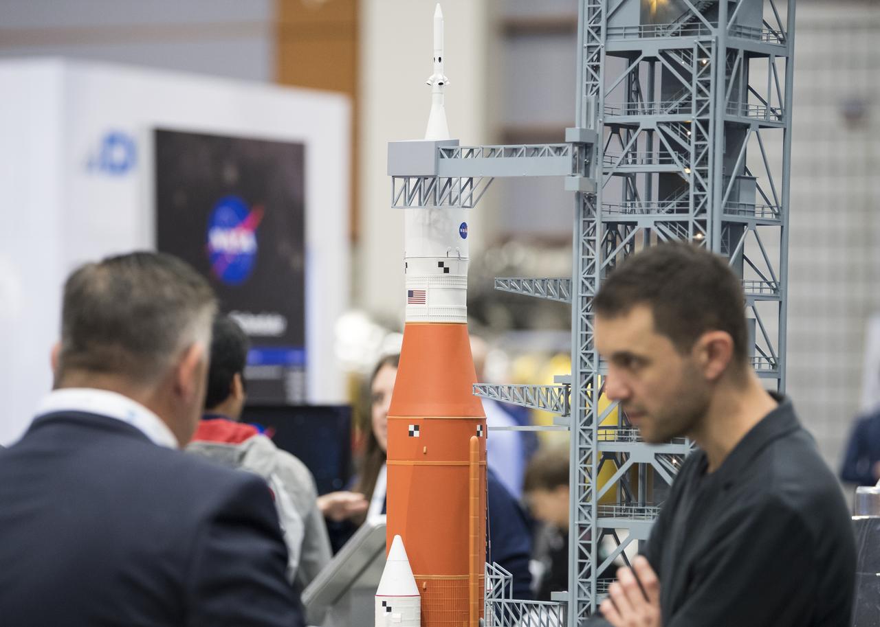
A model of NASA’s Space Launch System rocket is seen in the agency’s exhibit at the 70th International Astronautical Congress, Friday, Oct. 25, 2019 at the Walter E. Washington Convention Center in Washington. Photo Credit: (NASA/Joel Kowsky)
TEST ENGINEER DENNIS STRICKLAND CONDUCTS WATER FLOW TESTS AT TEST STAND 116 FOR SPACE LAUNCH SYSTEM SCALE MODEL ACOUSTIC TEST SERIES (WITH SOLID ROCKET BOOSTERS)
An inflatable model of NASA’s Space Launch System is seen prior to the National Symphony Orchestra’s performance of Gustav Holst’s “The Planets,” Wednesday, Jan. 22, 2020, at The Anthem in Washington, DC. Photo Credit: (NASA/Joel Kowsky)

CAPE CANAVERAL, Fla. – Faculty of the International Space University stand with their 1/60th scale model of the Space Launch System rocket during the rocket launch competition of the ISU's summer session. The competition was conducted at Launch Complex 39A at NASA's Kennedy Space Center in Florida, which co-hosted this year's ISU. Six teams designed and built large model rockets, each between three and five feet tall, and launched them from Launch Pad 39A, the starting point for Apollo missions to the moon and dozens of space shuttle flights. Each launch carried a raw egg, dubbed "eggstronauts" and had to recover it intact to be declared successful. Photo credit: NASA/Charisse Nahsser
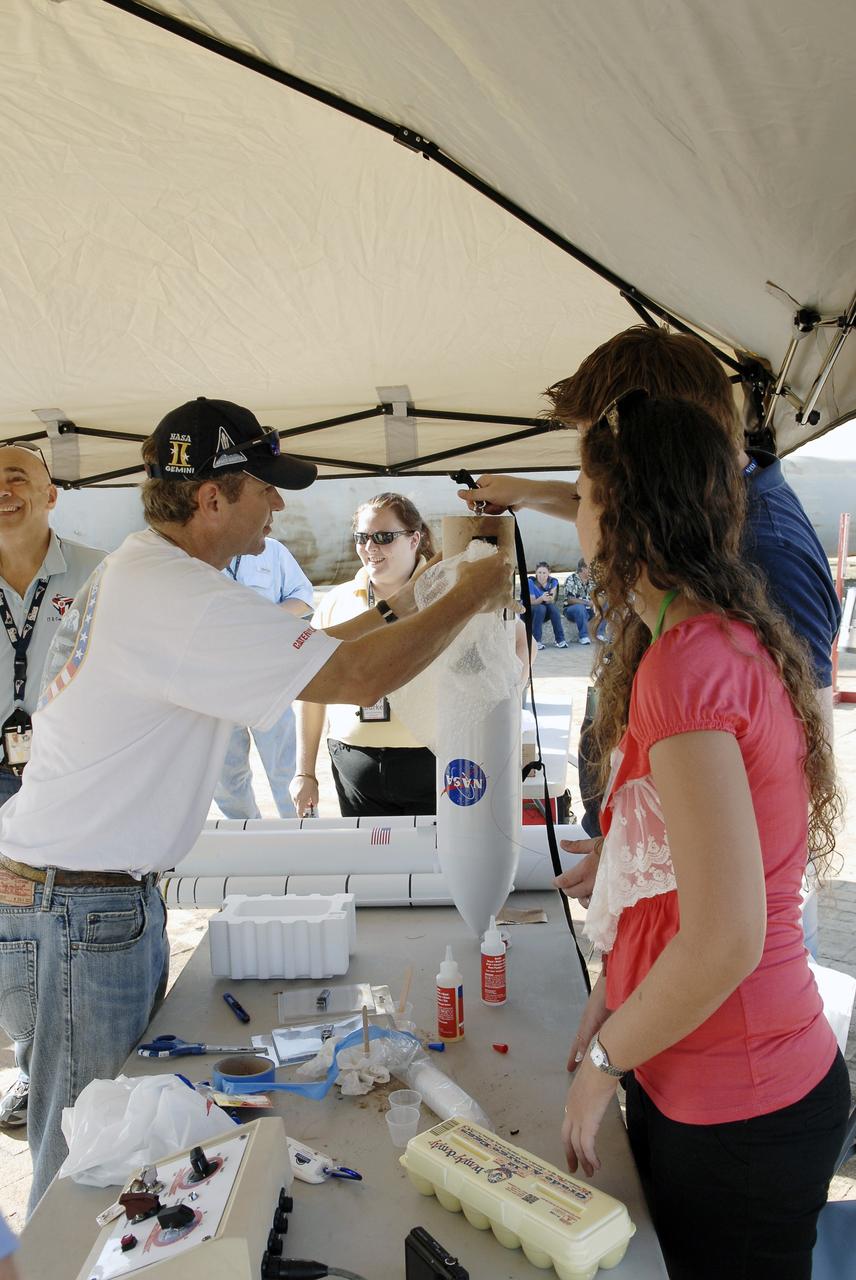
CAPE CANAVERAL, Fla. – Faculty of the International Space University assemble their 1/60th scale model of the Space Launch System rocket during the rocket launch competition of the ISU's summer session. The competition was conducted at Launch Complex 39A at NASA's Kennedy Space Center in Florida, which co-hosted this year's ISU. Six teams designed and built large model rockets, each between three and five feet tall, and launched them from Launch Pad 39A, the starting point for Apollo missions to the moon and dozens of space shuttle flights. Each launch carried a raw egg, dubbed "eggstronauts" and had to recover it intact to be declared successful. Photo credit: NASA/Charisse Nahsser
An engineer works with a model of a United Launch Alliance Atlas V rocket with a Boeing CST-100 Starliner capsule inside a wind tunnel at NASA's Ames Research Center in California. The Starliner/Atlas V system is under development by Boeing and ULA in partnership with NASA's Commercial Crew Program to launch astronauts to the International Space Station.
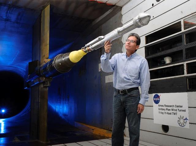
An engineer works with a model of a United Launch Alliance Atlas V rocket with a Boeing CST-100 Starliner capsule inside a wind tunnel at NASA's Ames Research Center in California. The Starliner/Atlas V system is under development by Boeing and ULA in partnership with NASA's Commercial Crew Program to launch astronauts to the International Space Station.
Senator Doug Jones (D-AL.) and wife, Louise, tour Marshall Space Flight facilities. Steve Doering, manager, Stages Element, Space Launch System (SLS) program at MSFC, explains the stages of the SLS rocket with the scale model rocket located in the lobby of building 4200.
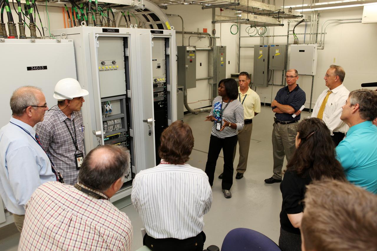
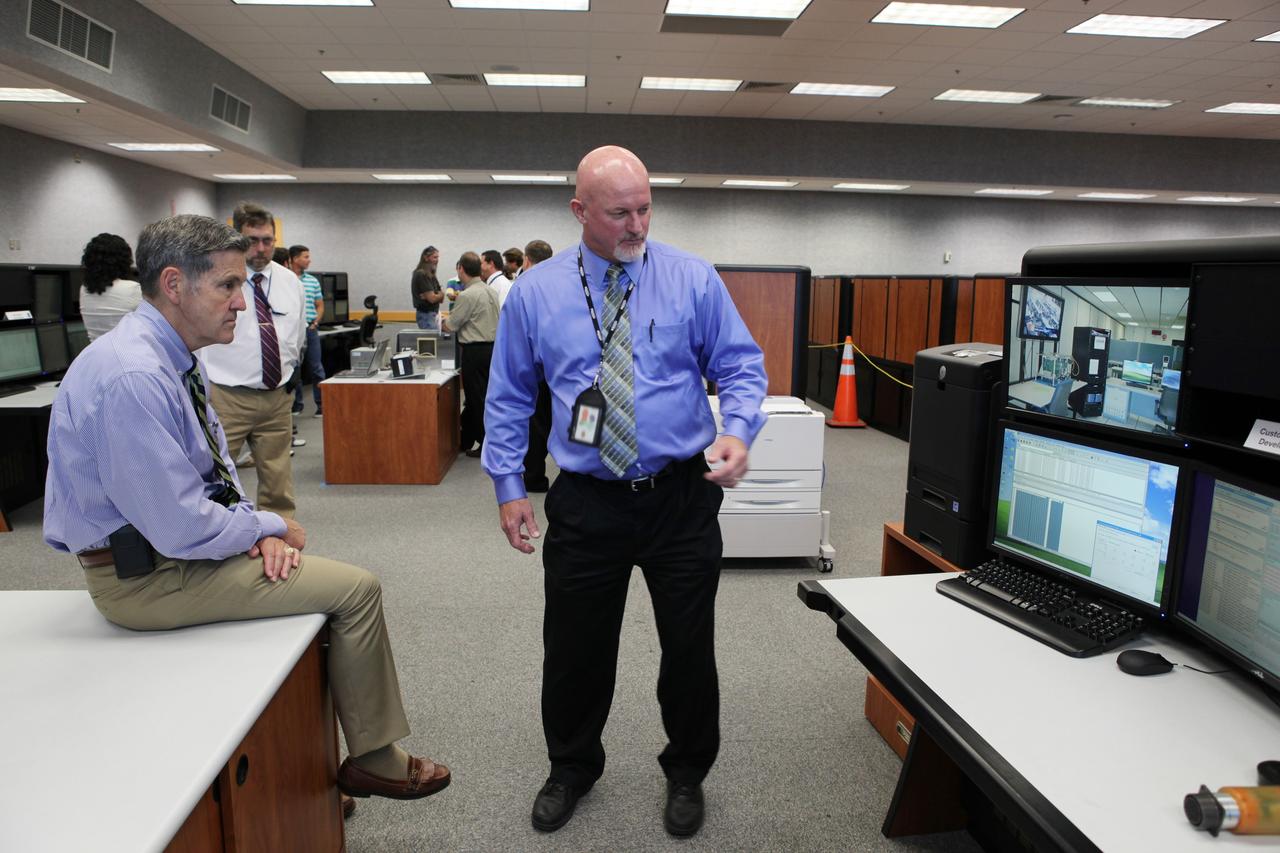
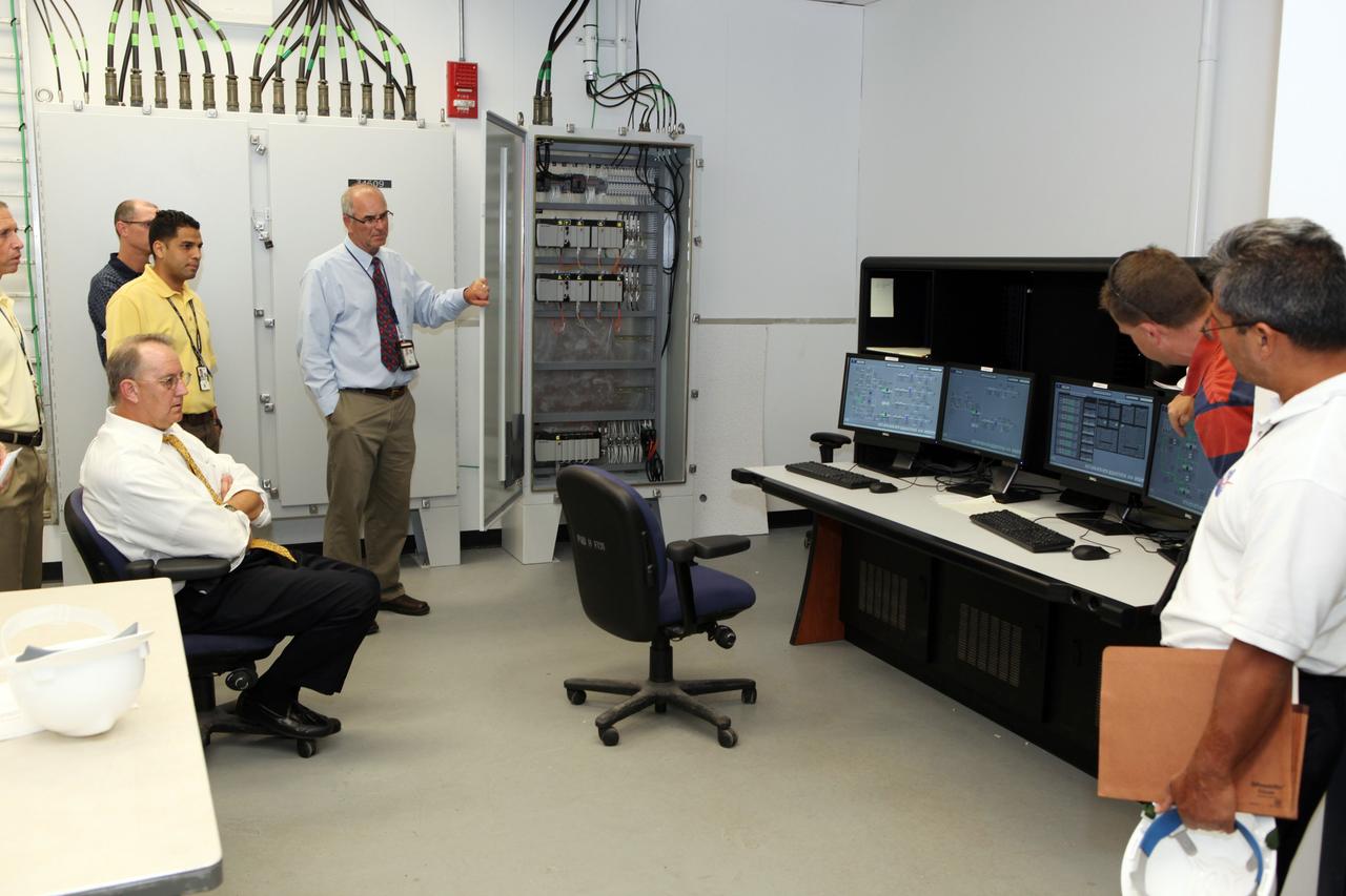
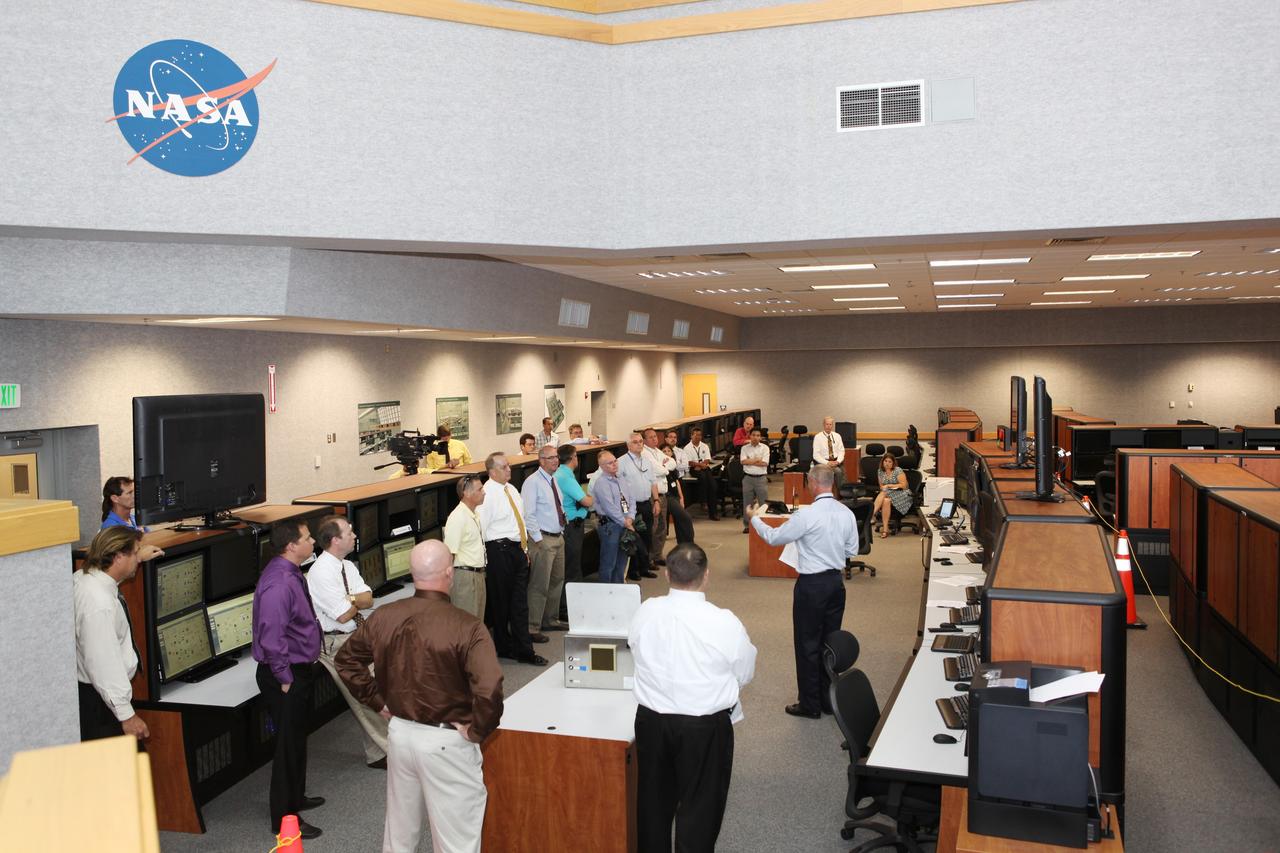
CAPE CANAVERAL, Fla. – Workers at NASA's Kennedy Space Center watch a demonstration of new systems installed in Launch Pad 39B. The renovation has been led by the Ground Systems Development and Operations Program based at Kennedy. The new systems are designed to be flexible so controllers can process and launch multiple types of rockets and spacecraft, whether they are government or commercial models. Photo credit: NASA/Dmitri Gerondidakis
CAPE CANAVERAL, Fla. – Workers at NASA's Kennedy Space Center watch a demonstration of new systems installed in Launch Pad 39B. The renovation has been led by the Ground Systems Development and Operations Program based at Kennedy. The new systems are designed to be flexible so controllers can process and launch multiple types of rockets and spacecraft, whether they are government or commercial models. Photo credit: NASA/Dmitri Gerondidakis

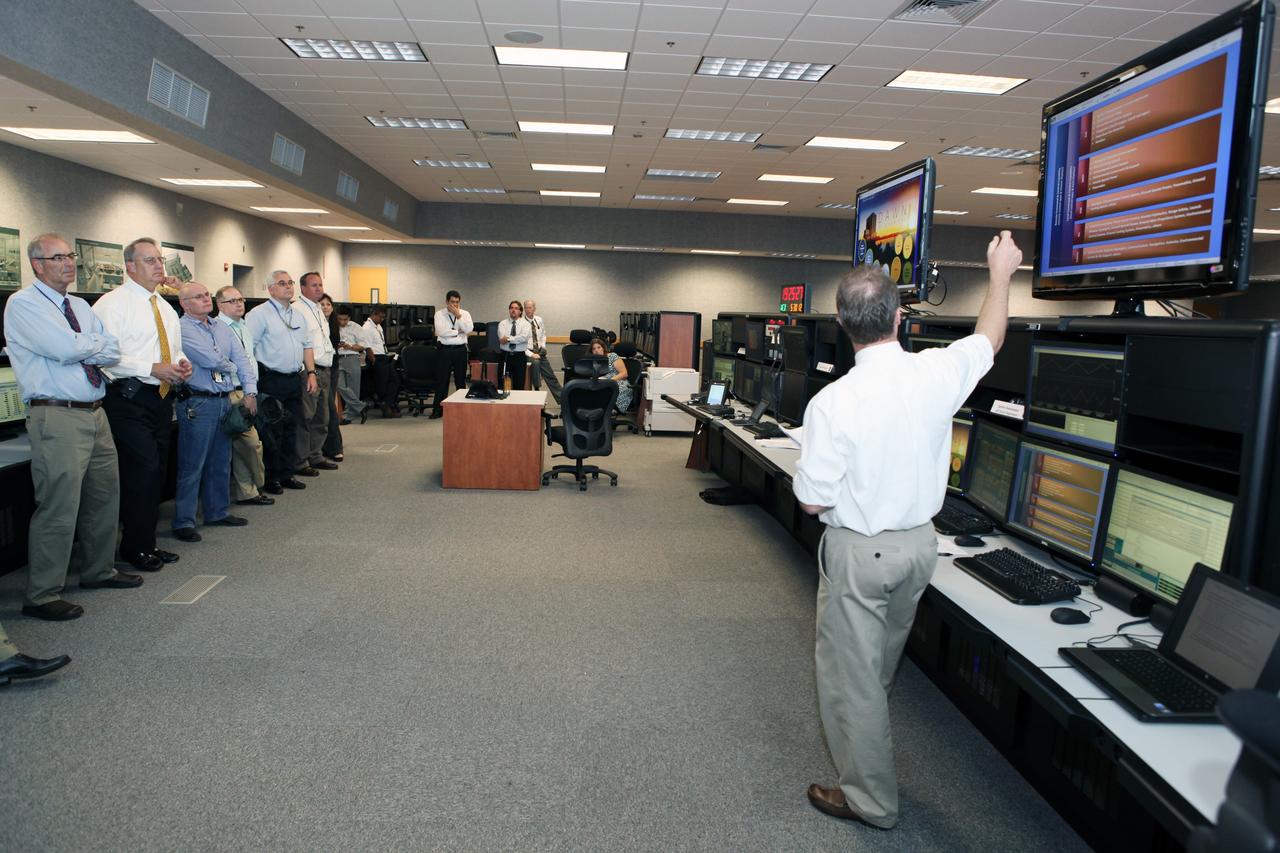
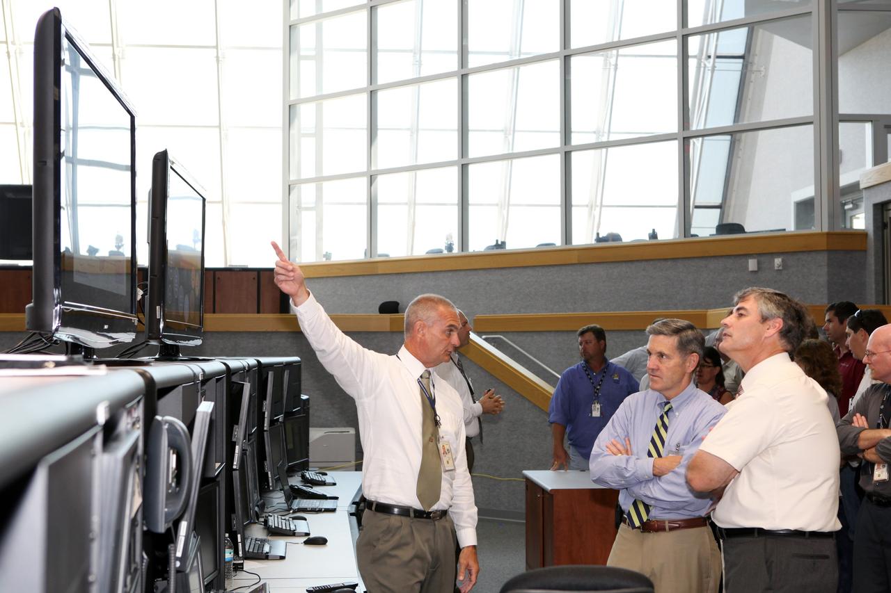
CAPE CANAVERAL, Fla. – Robert Cabana, director of NASA's Kennedy Space Center and a former astronaut, takes a look inside new systems installed in the Young-Crippen Firing Room, also known as Firing Room 1, inside the Launch Control Center. The renovation has been led by the Ground Systems Development and Operations Program based at Kennedy. The new systems are designed to be flexible so controllers can process and launch multiple types of rockets and spacecraft, whether they are government or commercial models. Photo credit: NASA/Dmitri Gerondidakis
CAPE CANAVERAL, Fla. – Robert Cabana, director of NASA's Kennedy Space Center and a former astronaut, watches a demonstration of new systems installed in the Young-Crippen Firing Room, also known as Firing Room 1, inside the Launch Control Center. The renovation has been led by the Ground Systems Development and Operations Program based at Kennedy. The new systems are designed to be flexible so controllers can process and launch multiple types of rockets and spacecraft, whether they are government or commercial models. Photo credit: NASA/Dmitri Gerondidakis
CAPE CANAVERAL, Fla. – Workers at NASA's Kennedy Space Center watch a demonstration of new systems installed in Launch Pad 39B. The renovation has been led by the Ground Systems Development and Operations Program based at Kennedy. The new systems are designed to be flexible so controllers can process and launch multiple types of rockets and spacecraft, whether they are government or commercial models. Photo credit: NASA/Dmitri Gerondidakis
CAPE CANAVERAL, Fla. – Workers at NASA's Kennedy Space Center watch a demonstration of new systems installed in Launch Pad 39B. The renovation has been led by the Ground Systems Development and Operations Program based at Kennedy. The new systems are designed to be flexible so controllers can process and launch multiple types of rockets and spacecraft, whether they are government or commercial models. Photo credit: NASA/Dmitri Gerondidakis
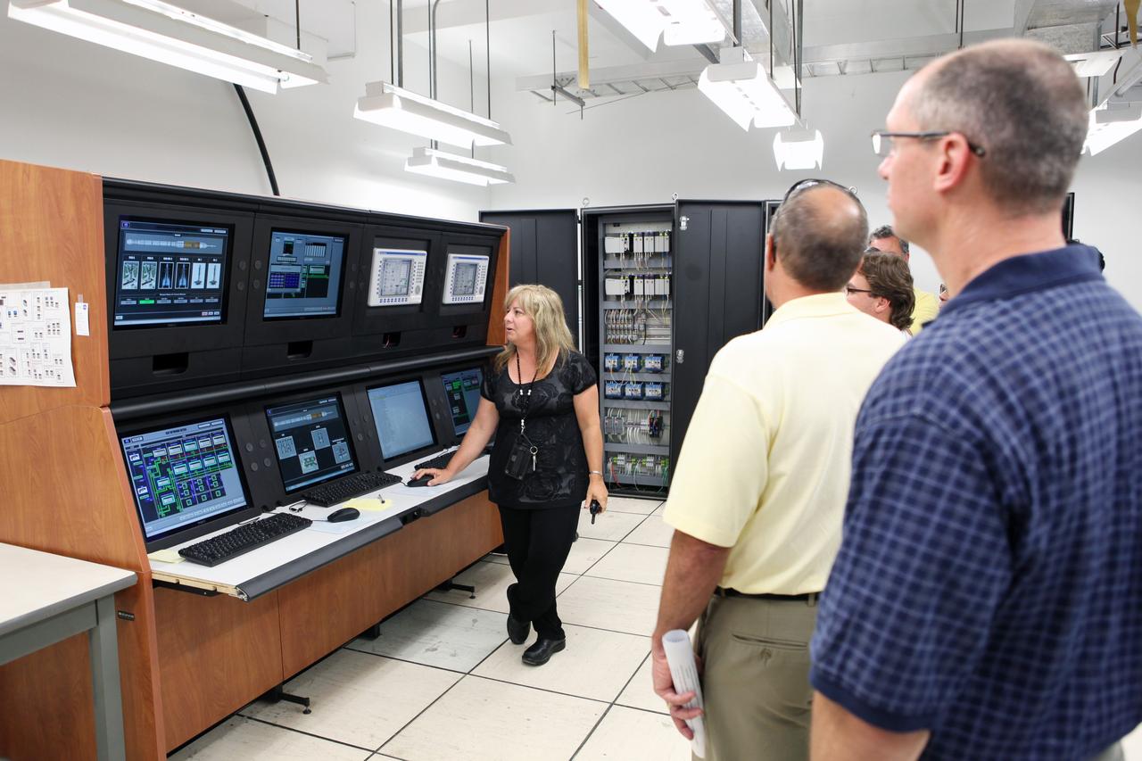
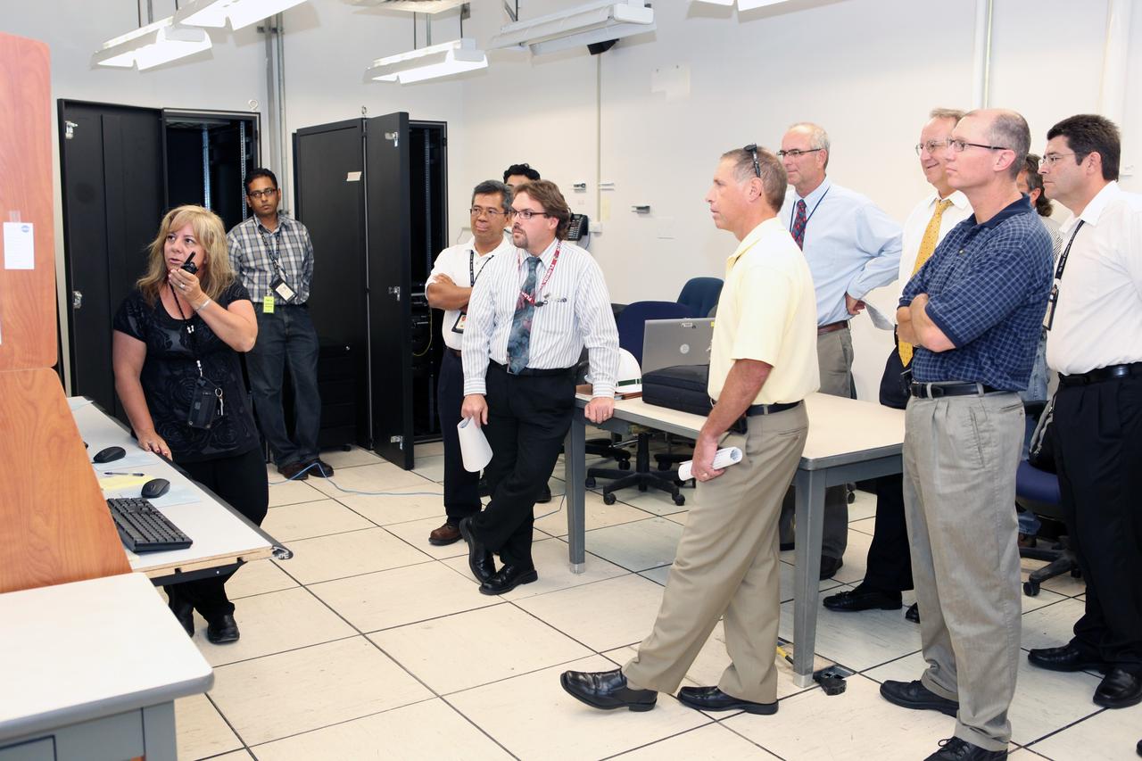
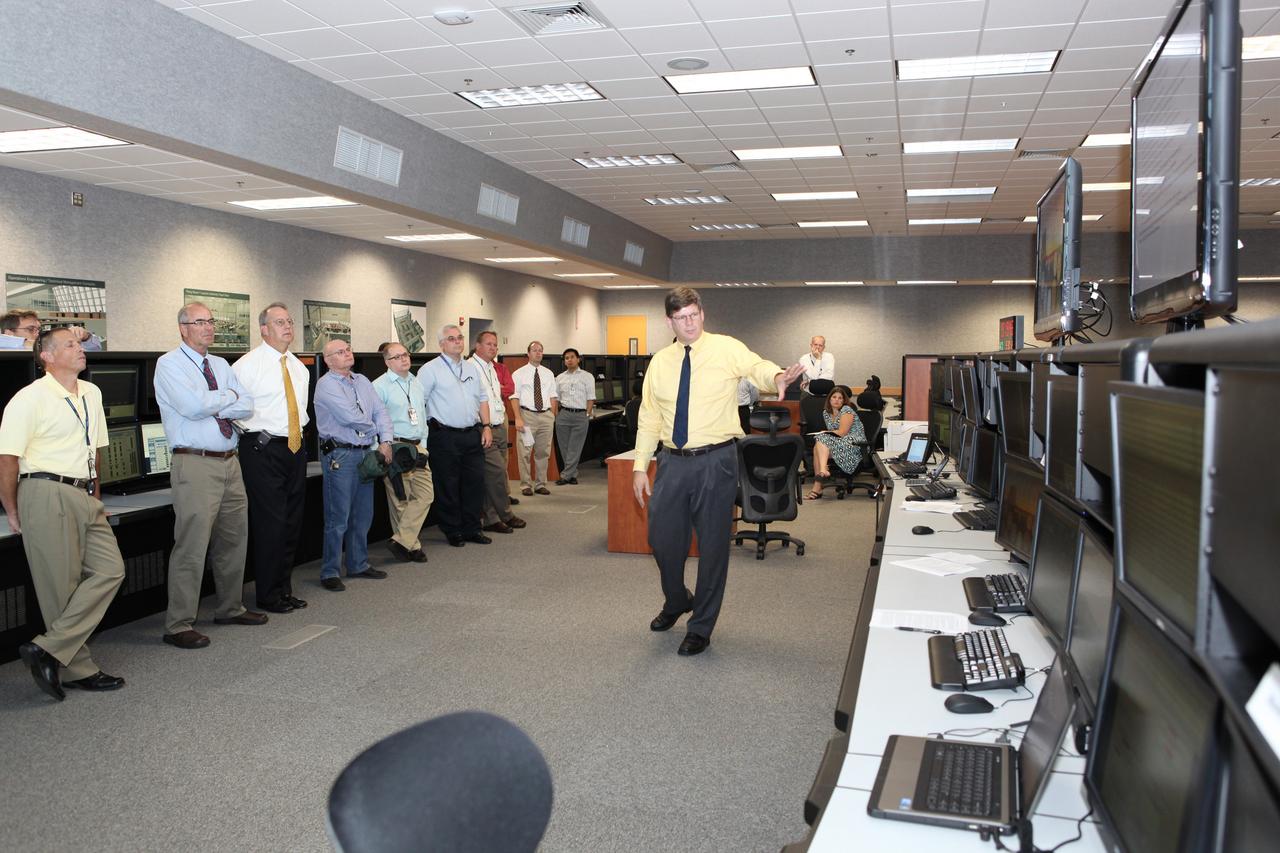
CAPE CANAVERAL, Fla. – Workers at NASA's Kennedy Space Center watch a demonstration of new systems installed in the Young-Crippen Firing Room, also known as Firing Room 1, inside the Launch Control Center. The renovation has been led by the Ground Systems Development and Operations Program based at Kennedy. The new systems are designed to be flexible so controllers can process and launch multiple types of rockets and spacecraft, whether they are government or commercial models. Photo credit: NASA/Dmitri Gerondidakis
CAPE CANAVERAL, Fla. – Workers at NASA's Kennedy Space Center watch a demonstration of new systems installed in Launch Pad 39B. The renovation has been led by the Ground Systems Development and Operations Program based at Kennedy. The new systems are designed to be flexible so controllers can process and launch multiple types of rockets and spacecraft, whether they are government or commercial models. Photo credit: NASA/Dmitri Gerondidakis
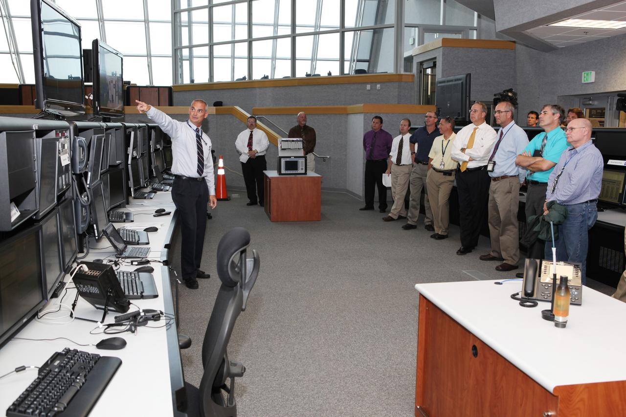
CAPE CANAVERAL, Fla. – Workers at NASA's Kennedy Space Center watch a demonstration of new systems installed in the Young-Crippen Firing Room, also known as Firing Room 1, inside the Launch Control Center. The renovation has been led by the Ground Systems Development and Operations Program based at Kennedy. The new systems are designed to be flexible so controllers can process and launch multiple types of rockets and spacecraft, whether they are government or commercial models. Photo credit: NASA/Dmitri Gerondidakis
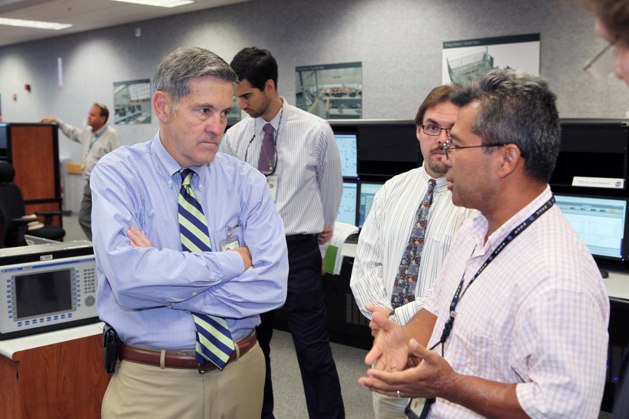
CAPE CANAVERAL, Fla. – Robert Cabana, director of NASA's Kennedy Space Center and a former astronaut, listens to a presentation of new systems installed in the Young-Crippen Firing Room, also known as Firing Room 1, inside the Launch Control Center. The renovation has been led by the Ground Systems Development and Operations Program based at Kennedy. The new systems are designed to be flexible so controllers can process and launch multiple types of rockets and spacecraft, whether they are government or commercial models. Photo credit: NASA/Dmitri Gerondidakis
CAPE CANAVERAL, Fla. – Robert Cabana, director of NASA's Kennedy Space Center and a former astronaut, watches a demonstration of new systems installed in the Young-Crippen Firing Room, also known as Firing Room 1, inside the Launch Control Center. The renovation has been led by the Ground Systems Development and Operations Program based at Kennedy. The new systems are designed to be flexible so controllers can process and launch multiple types of rockets and spacecraft, whether they are government or commercial models. Photo credit: NASA/Dmitri Gerondidakis
CAPE CANAVERAL, Fla. – Workers at NASA's Kennedy Space Center watch a demonstration of new systems installed in the Young-Crippen Firing Room, also known as Firing Room 1, inside the Launch Control Center. The renovation has been led by the Ground Systems Development and Operations Program based at Kennedy. The new systems are designed to be flexible so controllers can process and launch multiple types of rockets and spacecraft, whether they are government or commercial models. Photo credit: NASA/Dmitri Gerondidakis
CAPE CANAVERAL, Fla. – Workers at NASA's Kennedy Space Center watch a demonstration of new systems installed in the Young-Crippen Firing Room, also known as Firing Room 1, inside the Launch Control Center. The renovation has been led by the Ground Systems Development and Operations Program based at Kennedy. The new systems are designed to be flexible so controllers can process and launch multiple types of rockets and spacecraft, whether they are government or commercial models. Photo credit: NASA/Dmitri Gerondidakis
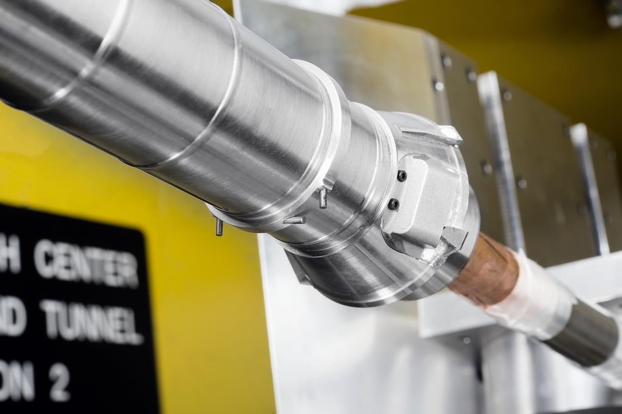
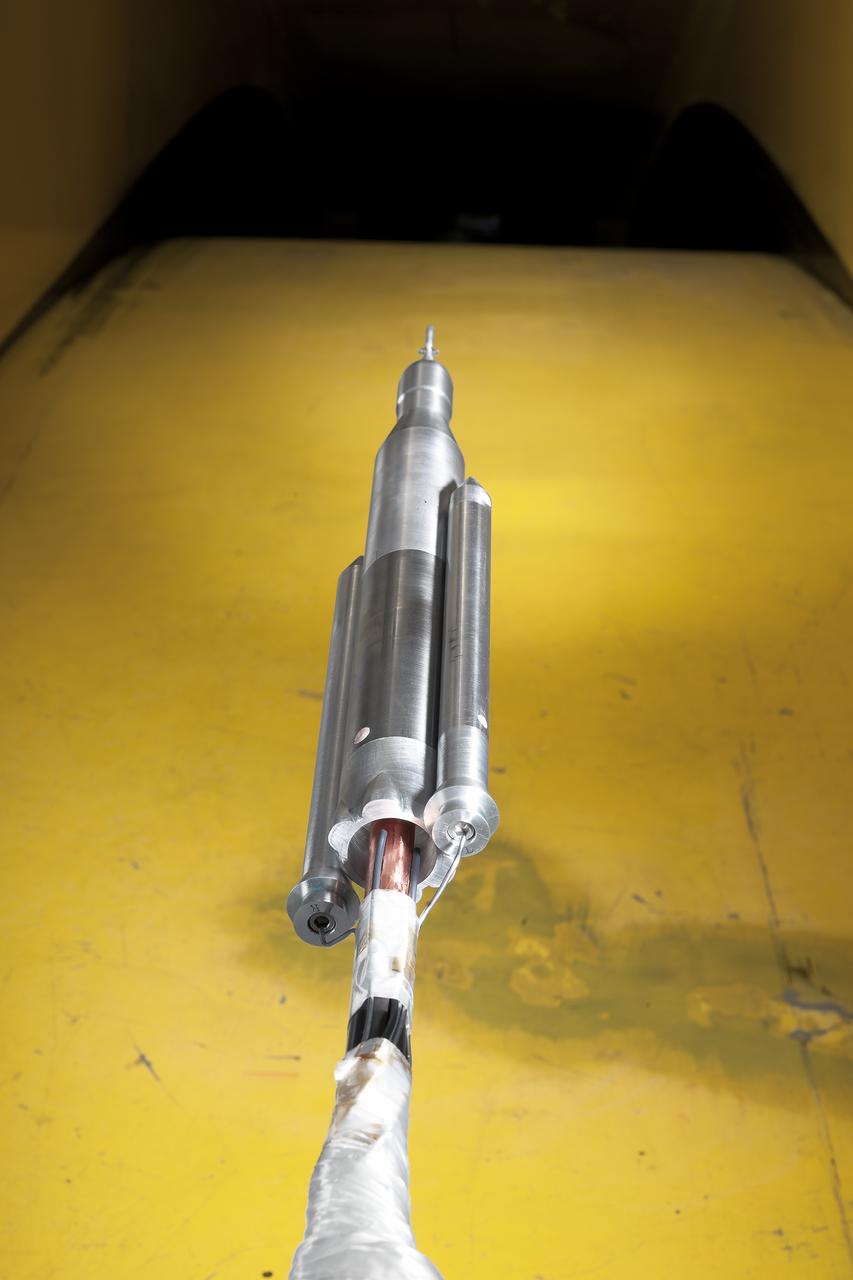
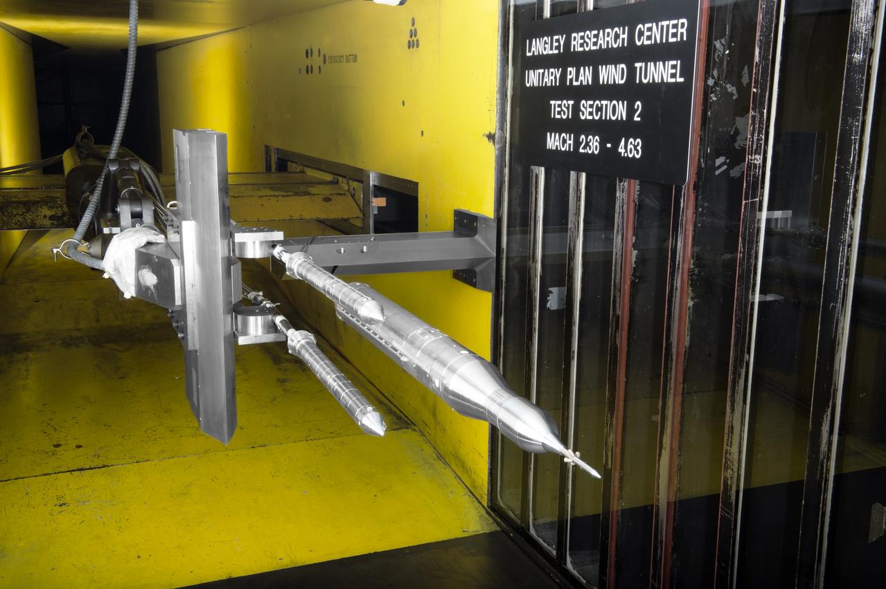
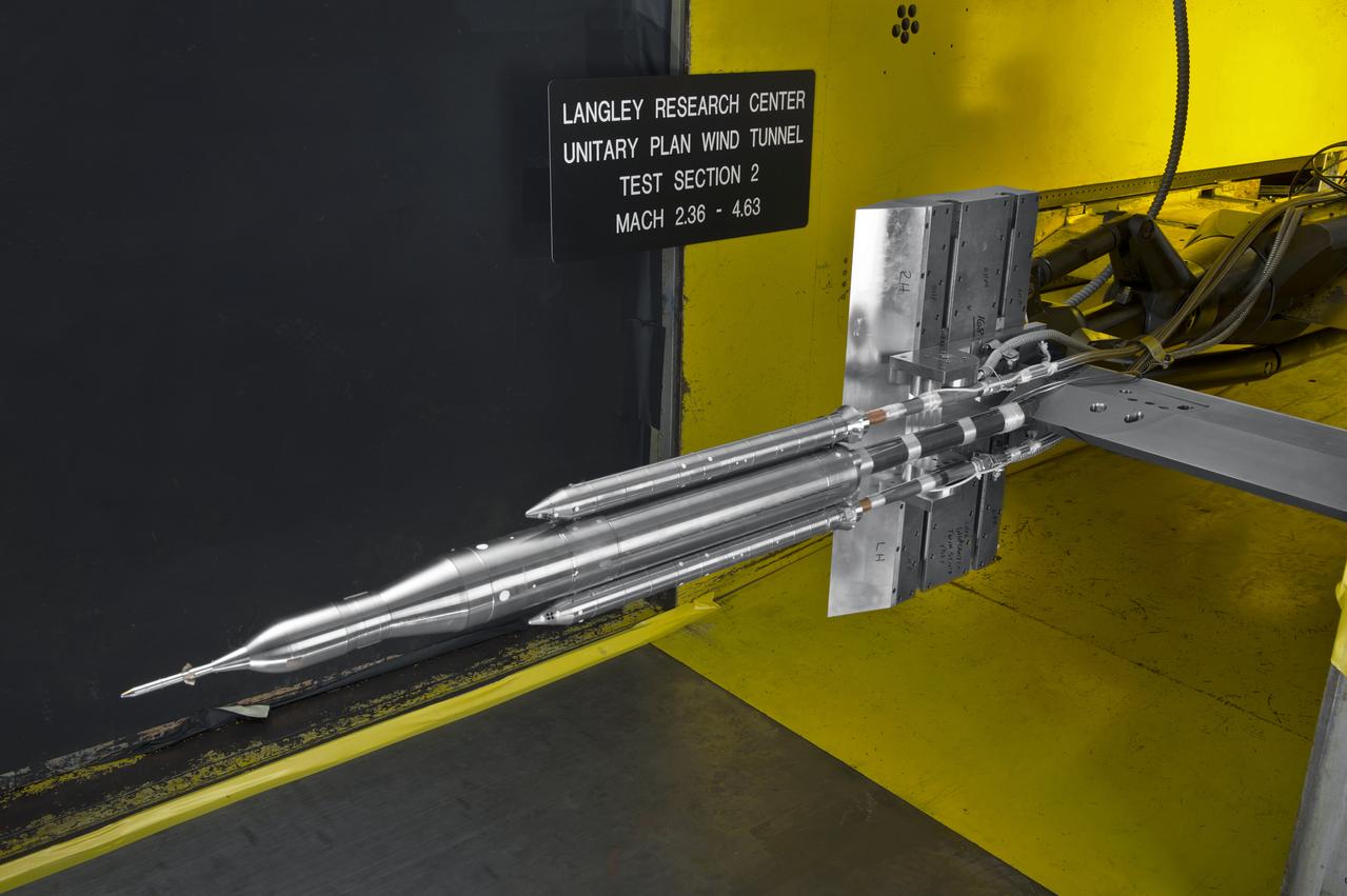
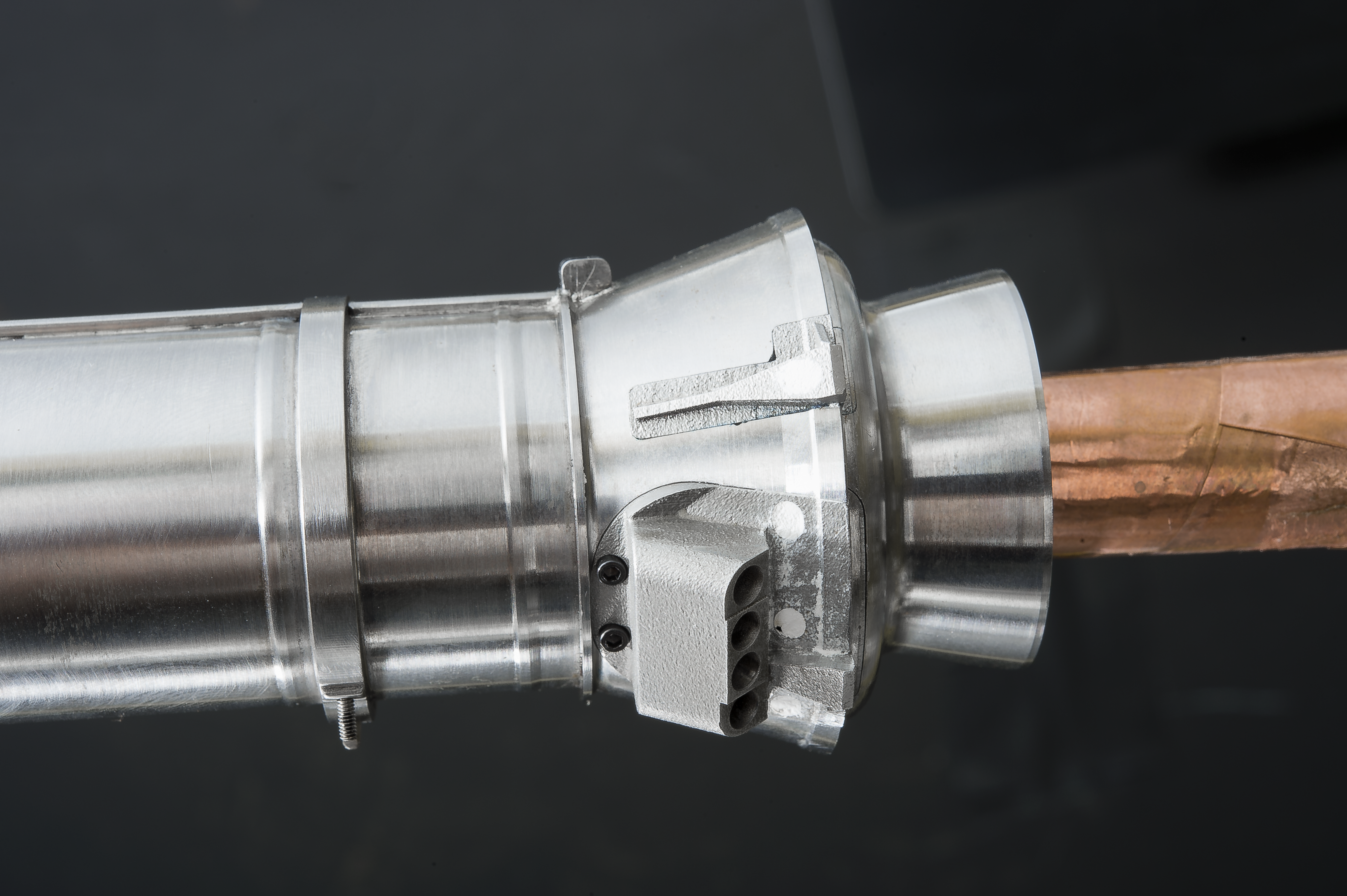
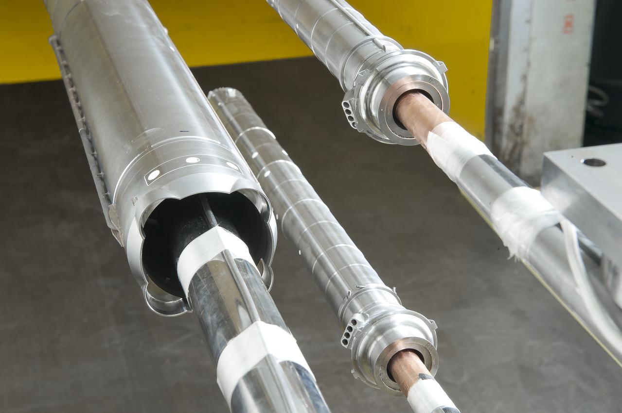
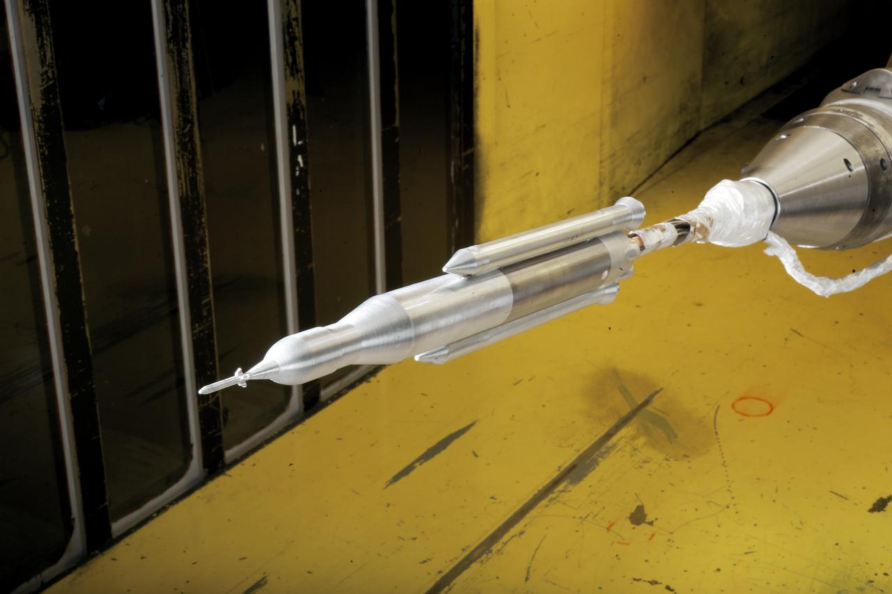
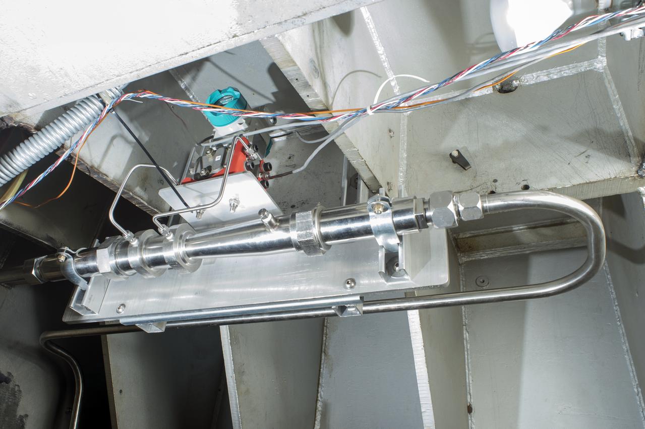
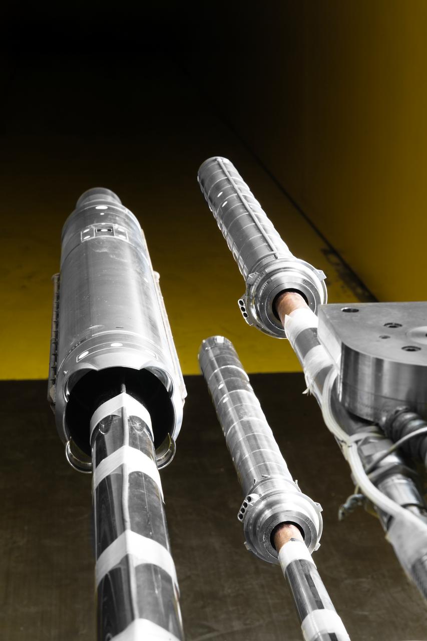
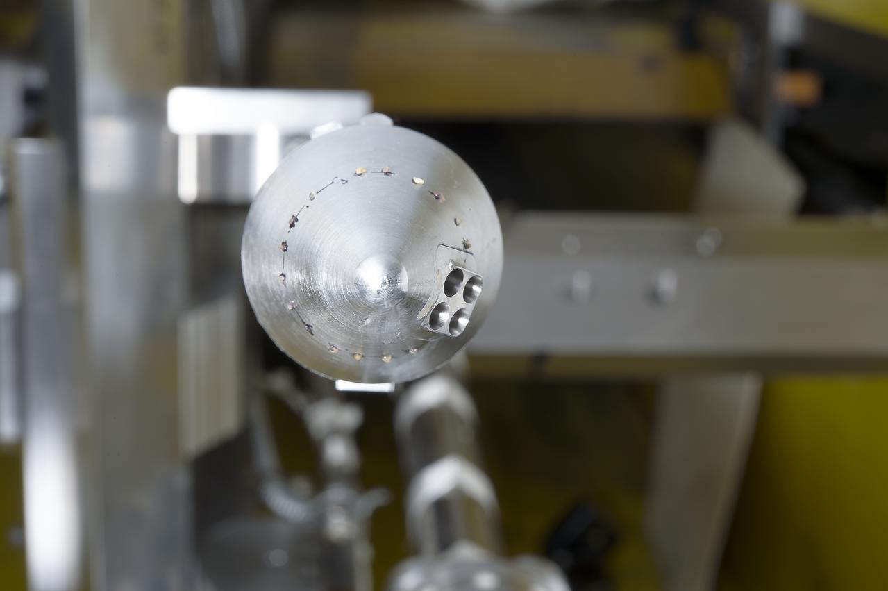
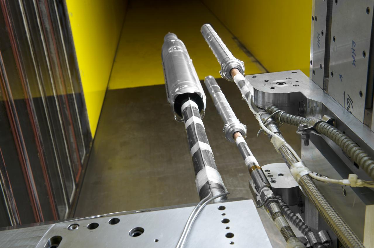
Stage Separation Test of the Space Launch System(SLS) in the Langley Unitary Plan Wind Tunnel (UPWT). The model used High Pressure air blown through the solid rocket boosters. (SRB) to simulate the booster separation motors (BSM) firing.
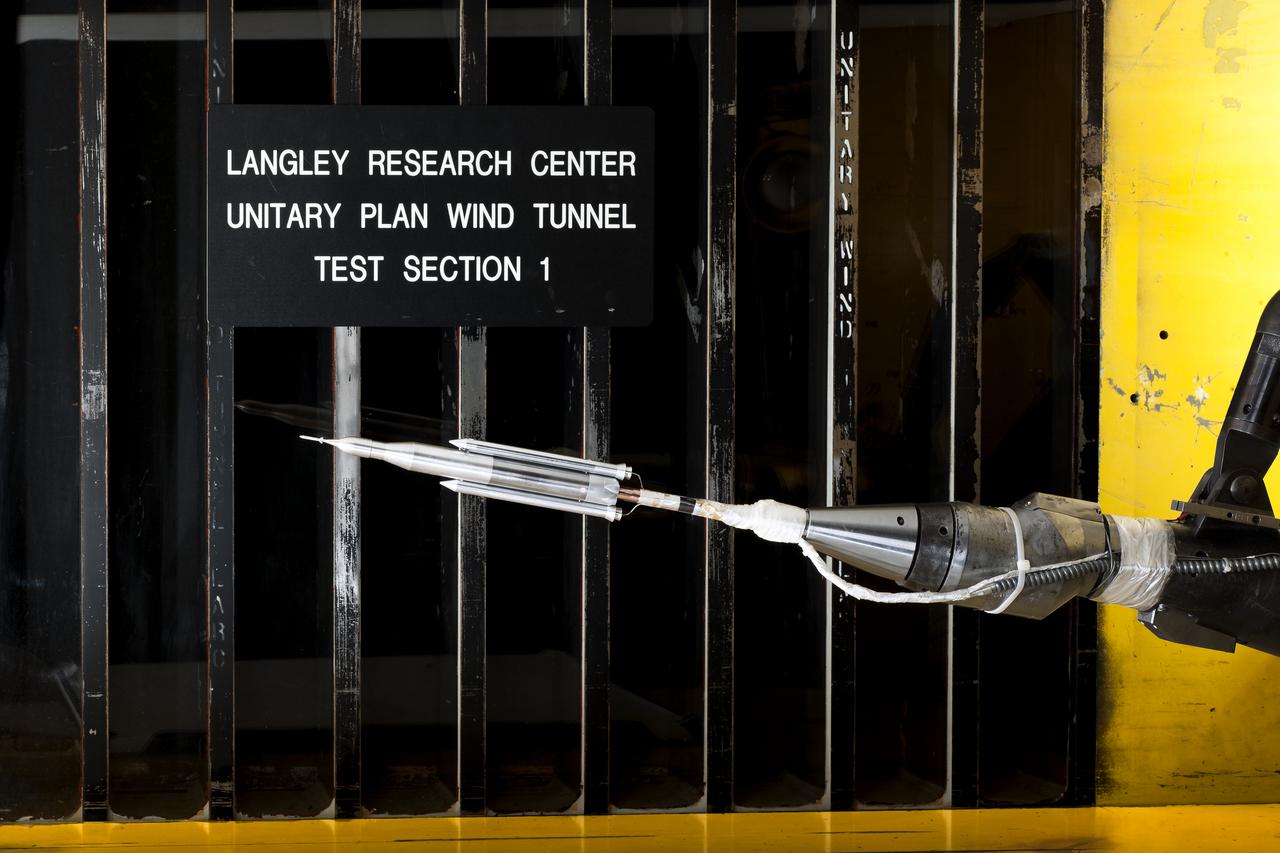
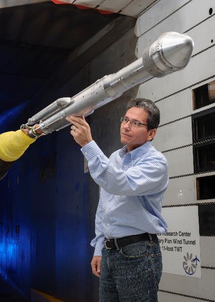
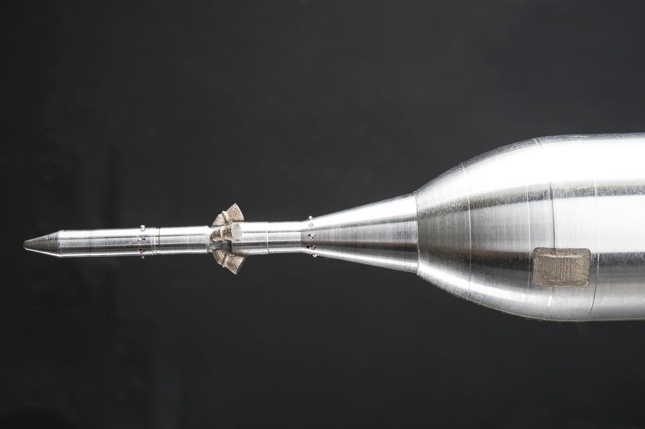
0.4 Percent Scale Space Launch System Wind Tunnel Test 0.4 Percent Scale SLS model installed in the NASA Langley Research Center Unitary Plan Wind Tunnel Test Section 1 for aerodynamic force and movement testing.
0.4 Percent Scale Space Launch System Wind Tunnel Test 0.4 Percent Scale SLS model installed in the NASA Langley Research Center Unitary Plan Wind Tunnel Test Section 1 for aerodynamic force and movement testing.
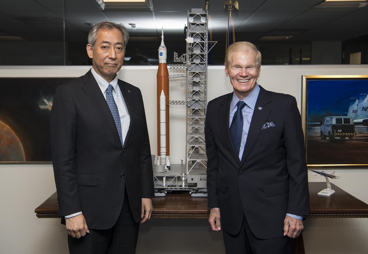
President of the Japan Aerospace Exploration Agency (JAXA), Hiroshi Yamakawa, left, and NASA Administrator Bill Nelson, pose for a photo next to a model of the Space Launch System (SLS) during a meeting, Thursday, April 7, 2022, at NASA Headquarters in Washington DC. Photo Credit: (NASA/Aubrey Gemignani)
Stage Separation Test of the Space Launch System(SLS) in the Langley Unitary Plan Wind Tunnel (UPWT). The model used High Pressure air blown through the solid rocket boosters. (SRB) to simulate the booster separation motors (BSM) firing.
Stage Separation Test of the Space Launch System(SLS) in the Langley Unitary Plan Wind Tunnel (UPWT). The model used High Pressure air blown through the solid rocket boosters. (SRB) to simulate the booster separation motors (BSM) firing.
Stage Separation Test of the Space Launch System(SLS) in the Langley Unitary Plan Wind Tunnel (UPWT). The model used High Pressure air blown through the solid rocket boosters. (SRB) to simulate the booster separation motors (BSM) firing.
Stage Separation Test of the Space Launch System(SLS) in the Langley Unitary Plan Wind Tunnel (UPWT). The model used High Pressure air blown through the solid rocket boosters. (SRB) to simulate the booster separation motors (BSM) firing.
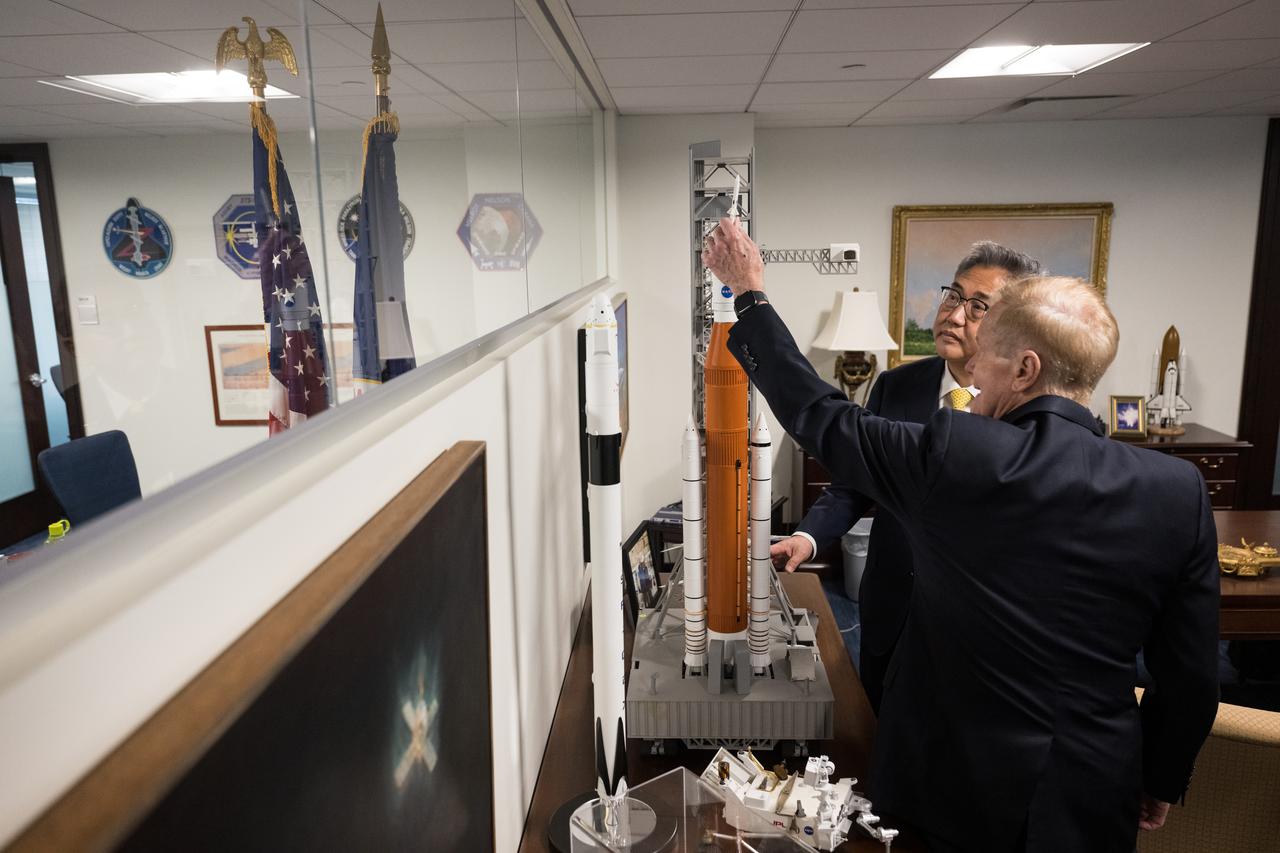
NASA Administrator Bill Nelson shows Republic of Korea Minister of Foreign Affairs, Jin Park, a model of the Space Launch System (SLS), Thursday, Feb. 2, 2023 at the Mary W. Jackson NASA Headquarters building in Washington DC. Photo Credit: (NASA/Aubrey Gemignani)

Stage Separation Test of the Space Launch System(SLS) in the Langley Unitary Plan Wind Tunnel (UPWT). The model used High Pressure air blown through the solid rocket boosters. (SRB) to simulate the booster separation motors (BSM) firing.
Stage Separation Test of the Space Launch System(SLS) in the Langley Unitary Plan Wind Tunnel (UPWT). The model used High Pressure air blown through the solid rocket boosters. (SRB) to simulate the booster separation motors (BSM) firing.
Stage Separation Test of the Space Launch System(SLS) in the Langley Unitary Plan Wind Tunnel (UPWT). The model used High Pressure air blown through the solid rocket boosters. (SRB) to simulate the booster separation motors (BSM) firing.
Stage Separation Test of the Space Launch System(SLS) in the Langley Unitary Plan Wind Tunnel (UPWT). The model used High Pressure air blown through the solid rocket boosters. (SRB) to simulate the booster separation motors (BSM) firing.
0.4 Percent Scale Space Launch System Wind Tunnel Test 0.4 Percent Scale SLS model installed in the NASA Langley Research Center Unitary Plan Wind Tunnel Test Section 1 for aerodynamic force and movement testing.
Stage Separation Test of the Space Launch System(SLS) in the Langley Unitary Plan Wind Tunnel (UPWT). The model used High Pressure air blown through the solid rocket boosters. (SRB) to simulate the booster separation motors (BSM) firing.
Stage Separation Test of the Space Launch System(SLS) in the Langley Unitary Plan Wind Tunnel (UPWT). The model used High Pressure air blown through the solid rocket boosters. (SRB) to simulate the booster separation motors (BSM) firing.
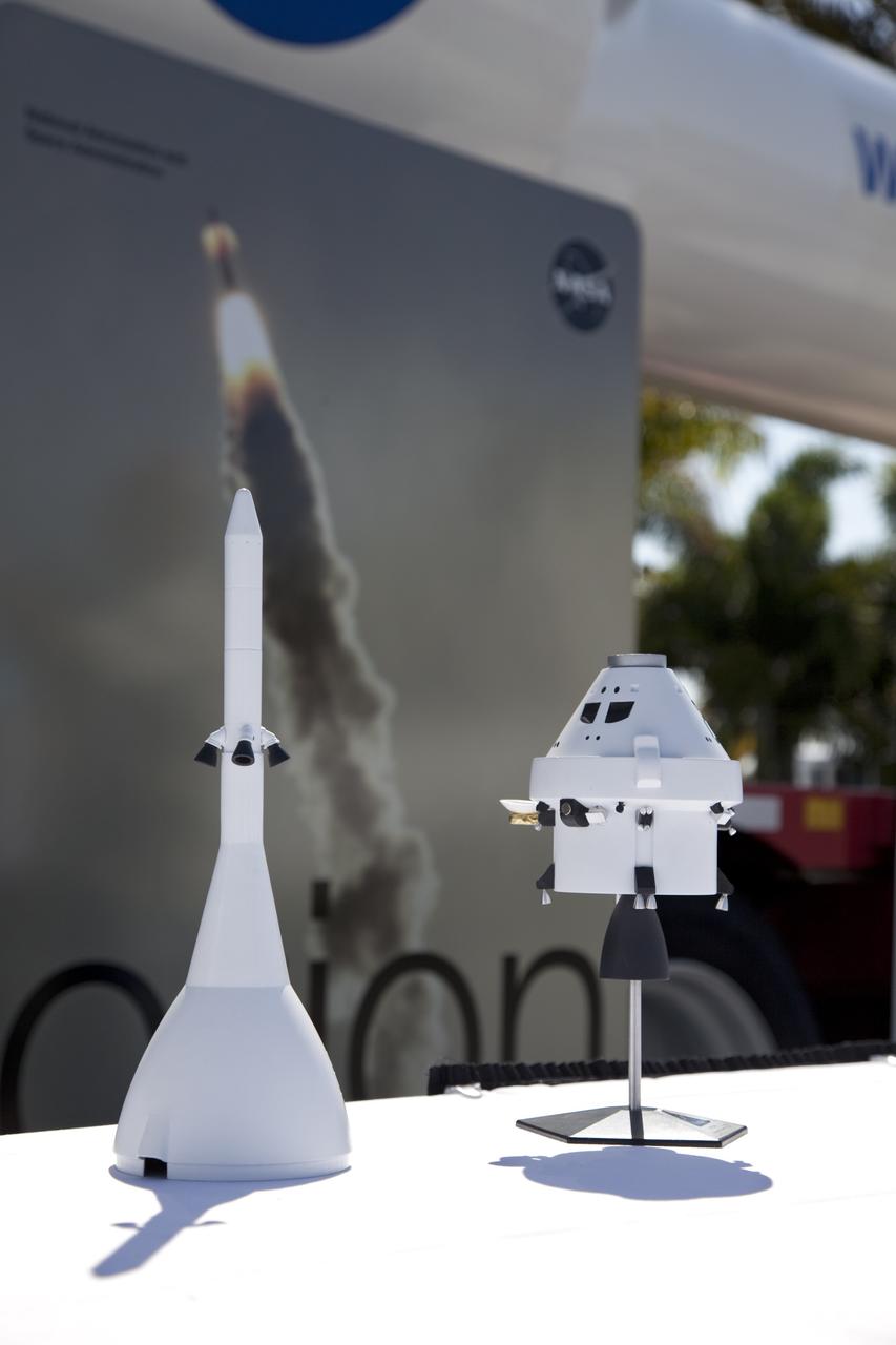
CAPE CANAVERAL, Fla. -- Models of an Orion crew exploration vehicle and its launch abort system are on display at the Kennedy Space Center Visitor Complex in Florida. For information on NASA's future plans, visit www.nasa.gov. Photo credit: NASA/Frankie Martin

Stage Separation Test of the Space Launch System(SLS) in the Langley Unitary Plan Wind Tunnel (UPWT). The model used High Pressure air blown through the solid rocket boosters. (SRB) to simulate the booster separation motors (BSM) firing.
Stage Separation Test of the Space Launch System(SLS) in the Langley Unitary Plan Wind Tunnel (UPWT). The model used High Pressure air blown through the solid rocket boosters. (SRB) to simulate the booster separation motors (BSM) firing.
Stage Separation Test of the Space Launch System(SLS) in the Langley Unitary Plan Wind Tunnel (UPWT). The model used High Pressure air blown through the solid rocket boosters. (SRB) to simulate the booster separation motors (BSM) firing.

0.4 Percent Scale Space Launch System Wind Tunnel Test 0.4 Percent Scale SLS model installed in the NASA Langley Research Center Unitary Plan Wind Tunnel Test Section 1 for aerodynamic force and movement testing.
Stage Separation Test of the Space Launch System(SLS) in the Langley Unitary Plan Wind Tunnel (UPWT). The model used High Pressure air blown through the solid rocket boosters. (SRB) to simulate the booster separation motors (BSM) firing.
Stage Separation Test of the Space Launch System(SLS) in the Langley Unitary Plan Wind Tunnel (UPWT). The model used High Pressure air blown through the solid rocket boosters. (SRB) to simulate the booster separation motors (BSM) firing.
NASA Administrator Bill Nelson shows Israel’s Minister of Innovation, Science, and Technology, Ofir Akunis, a model of the Space Launch System (SLS), Monday, March 27, 2023 at the Mary W. Jackson NASA Headquarters building in Washington DC. Photo Credit: (NASA/Aubrey Gemignani)
Stage Separation Test of the Space Launch System(SLS) in the Langley Unitary Plan Wind Tunnel (UPWT). The model used High Pressure air blown through the solid rocket boosters. (SRB) to simulate the booster separation motors (BSM) firing.
Stage Separation Test of the Space Launch System(SLS) in the Langley Unitary Plan Wind Tunnel (UPWT). The model used High Pressure air blown through the solid rocket boosters. (SRB) to simulate the booster separation motors (BSM) firing.
0.4 Percent Scale Space Launch System Wind Tunnel Test 0.4 Percent Scale SLS model installed in the NASA Langley Research Center Unitary Plan Wind Tunnel Test Section 1 for aerodynamic force and movement testing.
Stage Separation Test of the Space Launch System(SLS) in the Langley Unitary Plan Wind Tunnel (UPWT). The model used High Pressure air blown through the solid rocket boosters. (SRB) to simulate the booster separation motors (BSM) firing.

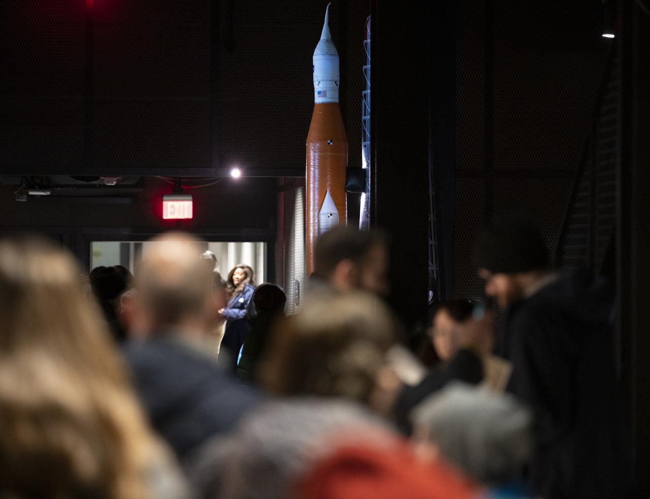
Attendees walk past an inflatable model of NASA's Space Launch System during Sneak Peek Friday at the USA Science and Engineering Festival, Friday, April 6, 2018 at the Walter E. Washington Convention Center in Washington, DC. The festival is open to the public April 7-8. Photo Credit: (NASA/Joel Kowsky)
Stage Separation Test of the Space Launch System(SLS) in the Langley Unitary Plan Wind Tunnel (UPWT). The model used High Pressure air blown through the solid rocket boosters. (SRB) to simulate the booster separation motors (BSM) firing.
Stage Separation Test of the Space Launch System(SLS) in the Langley Unitary Plan Wind Tunnel (UPWT). The model used High Pressure air blown through the solid rocket boosters. (SRB) to simulate the booster separation motors (BSM) firing.

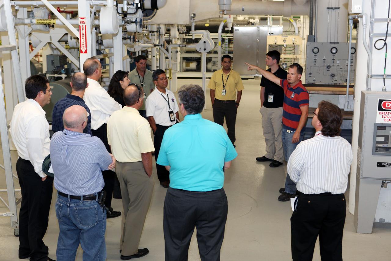
TITUSVILLE, Fla. – Visitors to the Tico Air Show near NASA's Kennedy Space Center in Florida take time to learn about the work the agency is pursuing and plans for future exploration. Visitors to the NASA booth found out about the Ground Systems Development and Operations Program, the Launch Services Program and the Commercial Crew Program, all based at Kennedy. They could also see models of spacecraft and rockets including the Space Launch System, or SLS. Photo credit: NASA/Dimitri Gerondidokis
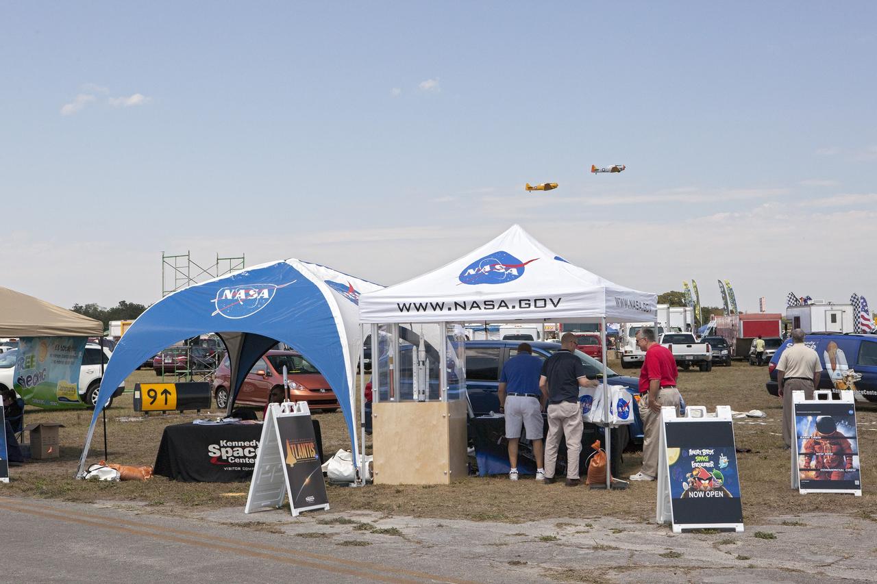
TITUSVILLE, Fla. – Visitors to the Tico Air Show near NASA's Kennedy Space Center in Florida take time to learn about the work the agency is pursuing and plans for future exploration. Visitors to the NASA booth found out about the Ground Systems Development and Operations Program, the Launch Services Program and the Commercial Crew Program, all based at Kennedy. They could also see models of spacecraft and rockets including the Space Launch System, or SLS. Photo credit: NASA/Dimitri Gerondidokis
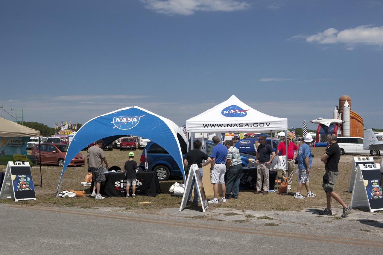
TITUSVILLE, Fla. – Visitors to the Tico Air Show near NASA's Kennedy Space Center in Florida take time to learn about the work the agency is pursuing and plans for future exploration. Visitors to the NASA booth found out about the Ground Systems Development and Operations Program, the Launch Services Program and the Commercial Crew Program, all based at Kennedy. They could also see models of spacecraft and rockets including the Space Launch System, or SLS. Photo credit: NASA/Dimitri Gerondidokis
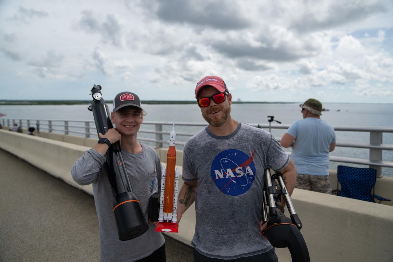
Two individuals wearing NASA shirts and holding a model Space Launch System rocket are on the Max Brewer Bridge in Titusville, Florida, to witness the launch of NASA’s Artemis I mission on Sept. 3, 2022. The launch was waived off for the day. The first in a series of increasingly complex missions, Artemis I will provide a foundation for human deep space exploration and demonstrate our commitment and capability to extend human presence to the Moon and beyond. The primary goal of Artemis I is to thoroughly test the integrated systems before crewed missions by operating the spacecraft in a deep space environment, testing Orion’s heat shield, and recovering the crew module after reentry, descent, and splashdown.
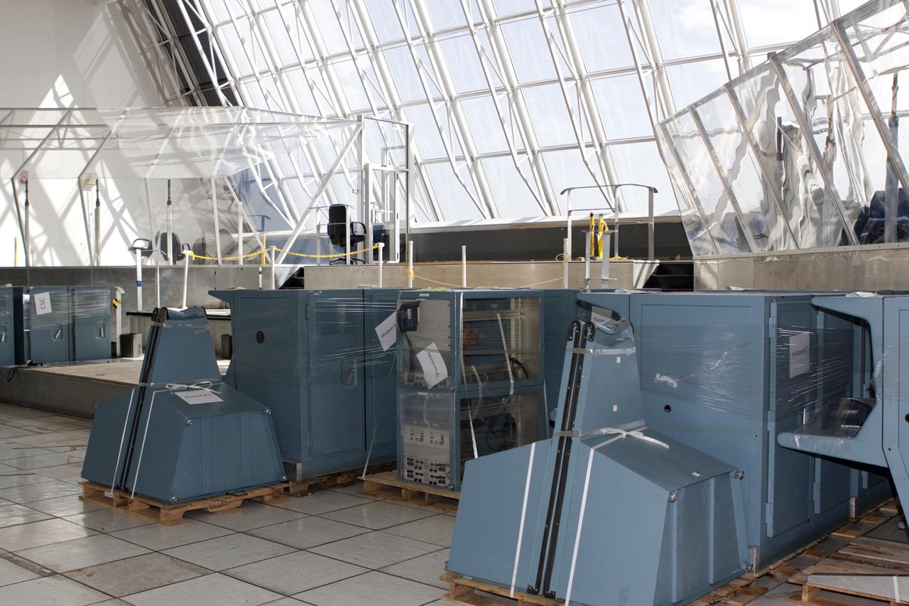
CAPE CANAVERAL, Fla. - In Firing Room 3 of the Launch Control Center at NASA’s Kennedy Space Center in Florida, legacy consoles and monitors are being removed to make way for new systems designed to be flexible so controllers can process and launch multiple types of rockets and spacecraft, whether they are government or commercial models. KSC’s Launch Complex 39 is transitioning to support multiple users with the Firing Rooms being modified to be more generic in nature for upcoming programs. Photo credit: NASA/Jim Grossmann
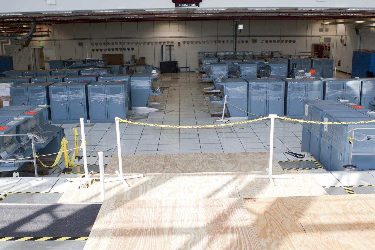
CAPE CANAVERAL, Fla. - In Firing Room 3 of the Launch Control Center at NASA’s Kennedy Space Center in Florida, legacy consoles and monitors are being removed to make way for new systems designed to be flexible so controllers can process and launch multiple types of rockets and spacecraft, whether they are government or commercial models. KSC’s Launch Complex 39 is transitioning to support multiple users with the Firing Rooms being modified to be more generic in nature for upcoming programs. Photo credit: NASA/Jim Grossmann
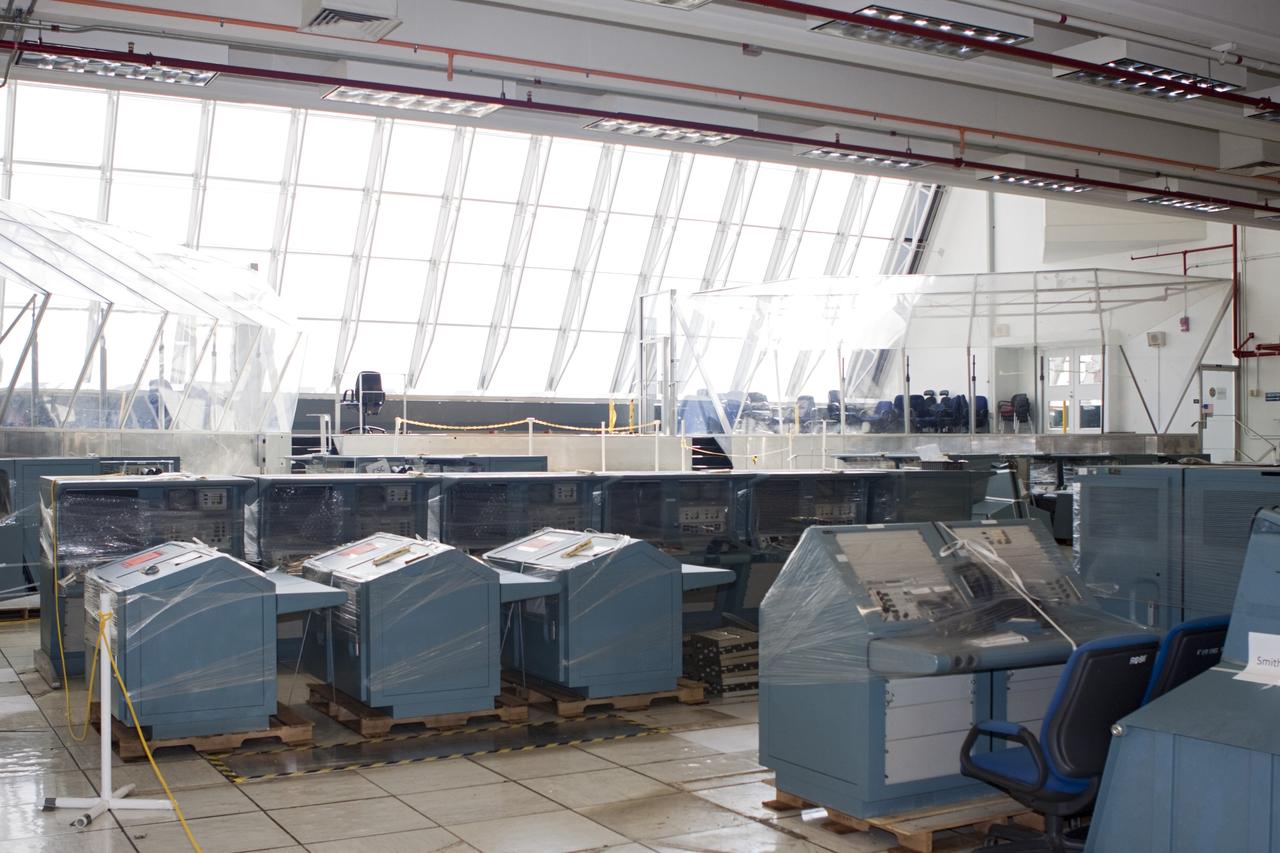
CAPE CANAVERAL, Fla. - In Firing Room 3 of the Launch Control Center at NASA’s Kennedy Space Center in Florida, legacy consoles and monitors are being removed to make way for new systems designed to be flexible so controllers can process and launch multiple types of rockets and spacecraft, whether they are government or commercial models. KSC’s Launch Complex 39 is transitioning to support multiple users with the Firing Rooms being modified to be more generic in nature for upcoming programs. Photo credit: NASA/Jim Grossmann
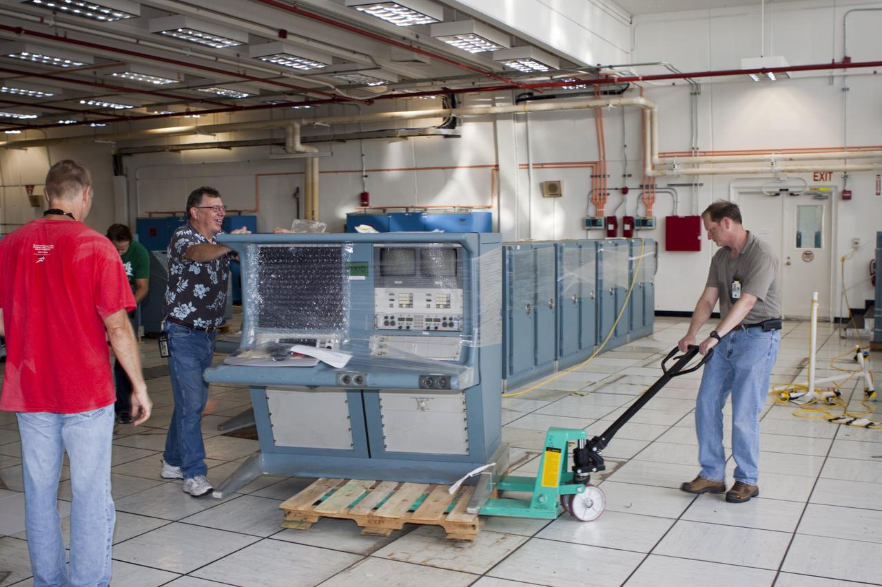
CAPE CANAVERAL, Fla. - In Firing Room 3 of the Launch Control Center at NASA’s Kennedy Space Center in Florida, technicians are removing legacy consoles and monitors to make way for new systems designed to be flexible so controllers can process and launch multiple types of rockets and spacecraft, whether they are government or commercial models. KSC’s Launch Complex 39 is transitioning to support multiple users with the Firing Rooms being modified to be more generic in nature for upcoming programs. Photo credit: NASA/Jim Grossmann
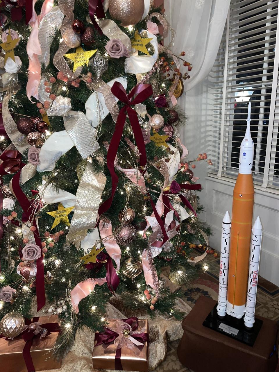
A model of NASA’s SLS (Space Launch System) rocket is part of the holiday display in the Mississippi Governor’s Mansion in Jackson, the official residence of state Gov. Tate Reeves. The model symbolizes the longtime relationship and shared history between the state of Mississippi and NASA’s Stennis Space Center near Bay St. Louis, Mississippi, the nation’s largest rocket propulsion test site. Built in the 1960s, NASA Stennis tested Apollo rocket stages that carried humans to the Moon and every main engine that helped launch 135 space shuttle missions. It now is testing engines and systems for NASA’s Artemis missions and operates as a powerful aerospace and technology hub for the region and state. “We are grateful for our ongoing relationship with the state of Mississippi,” NASA Stennis Director John Bailey said. “We appreciate every opportunity to highlight the role NASA Stennis and the state play in helping to power the nation’s human space exploration program. We look forward to 2025 and continuing our work to test engines and systems that will help launch Artemis missions back to the Moon and beyond.”
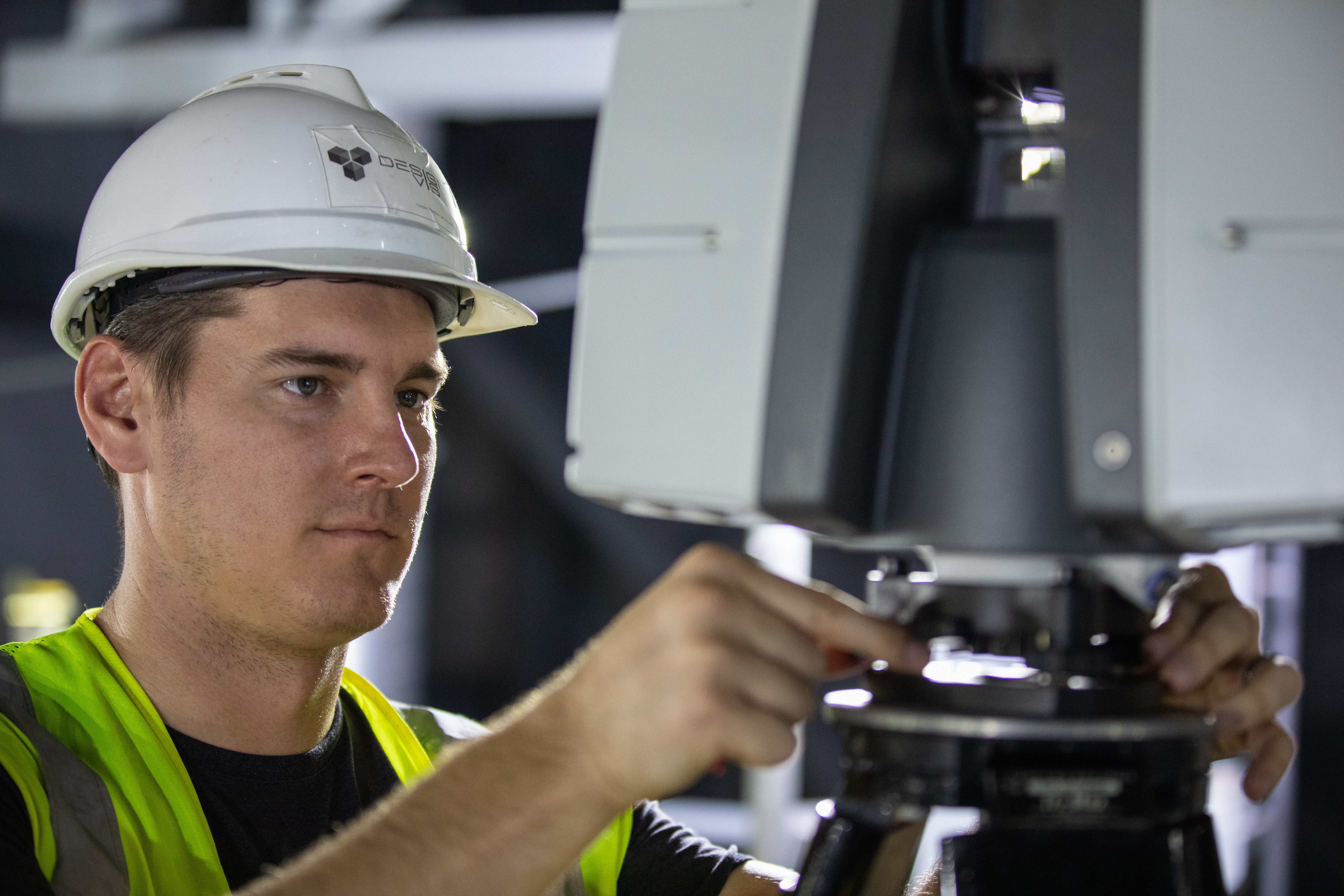
An engineer adjusts equipment from the Design Visualization Lab set up inside High Bay 3 of the Vehicle Assembly Building at NASA’s Kennedy Space Center on Oct. 14, 2020. The equipment will be used to do 3-D modeling of the mobile launcher that will carry the Space Launch System and Orion spacecraft to Launch Complex 39B for the Artemis I mission. Artemis I will test the Orion spacecraft and SLS as an integrated system ahead of crewed flights to the Moon. Under the Artemis program, NASA will land the first woman and the next man on the Moon in 2024.
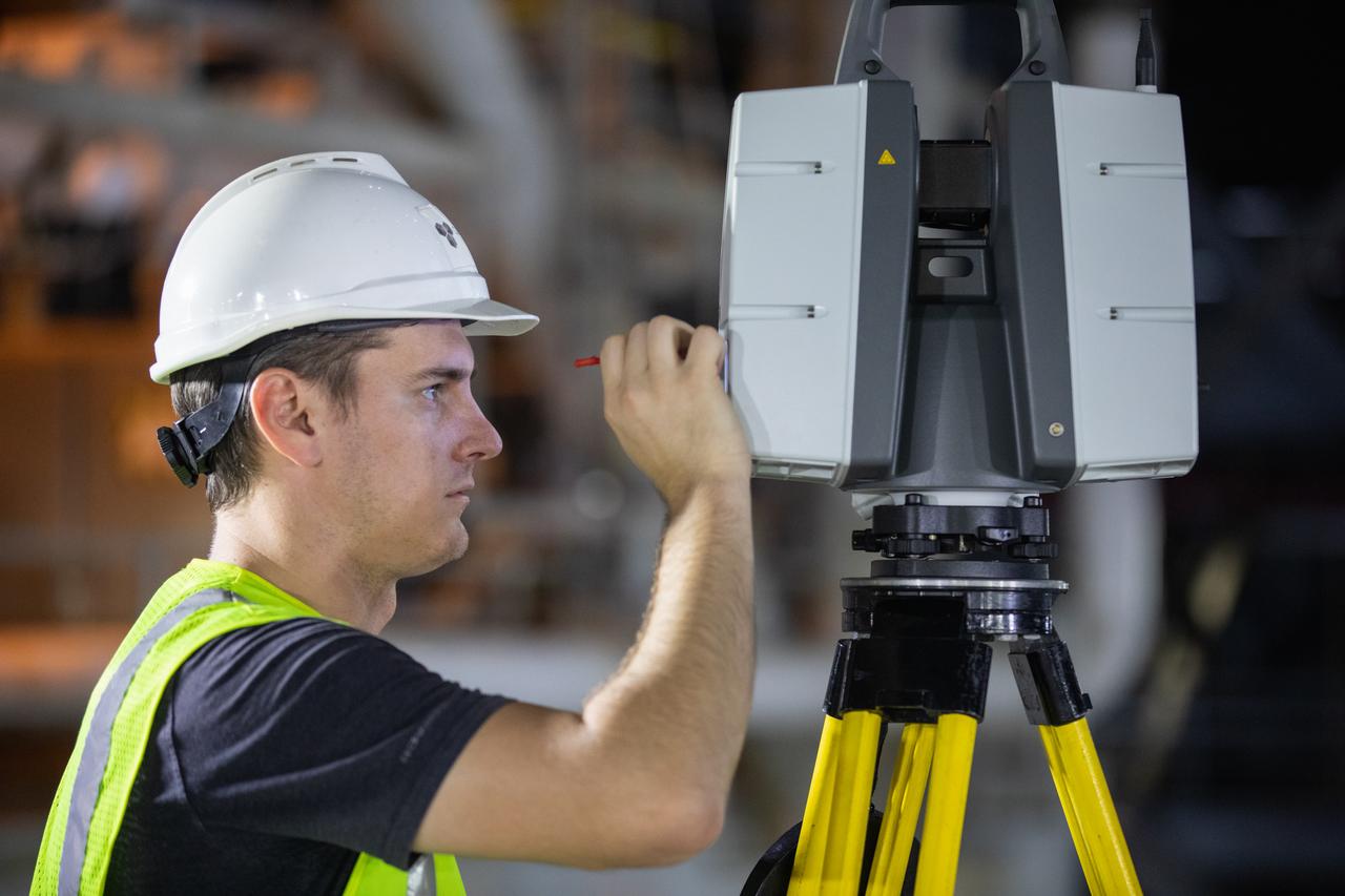
An engineer adjusts equipment from the Design Visualization Lab set up inside High Bay 3 of the Vehicle Assembly Building at NASA’s Kennedy Space Center on Oct. 14, 2020. The equipment will be used to do 3-D modeling of the mobile launcher that will carry the Space Launch System and Orion spacecraft to Launch Complex 39B for the Artemis I mission. Artemis I will test the Orion spacecraft and SLS as an integrated system ahead of crewed flights to the Moon. Under the Artemis program, NASA will land the first woman and the next man on the Moon in 2024.
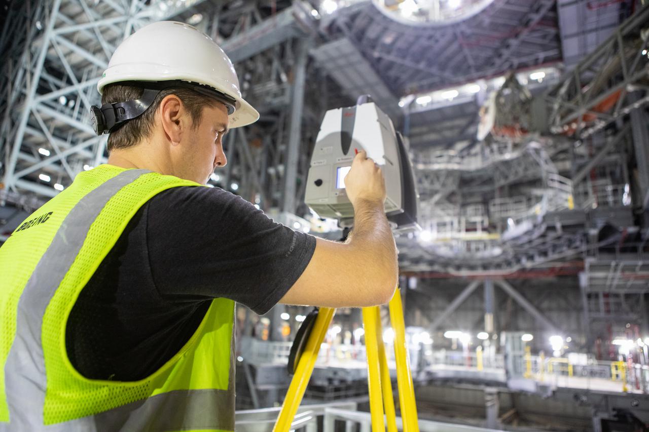
An engineer sets up equipment from the Design Visualization Lab inside High Bay 3 of the Vehicle Assembly Building at NASA’s Kennedy Space Center on Oct. 14, 2020. The equipment will be used to do 3-D modeling of the mobile launcher that will carry the Space Launch System and Orion spacecraft to Launch Complex 39B for the Artemis I mission. Artemis I will test the Orion spacecraft and SLS as an integrated system ahead of crewed flights to the Moon. Under the Artemis program, NASA will land the first woman and the next man on the Moon in 2024.
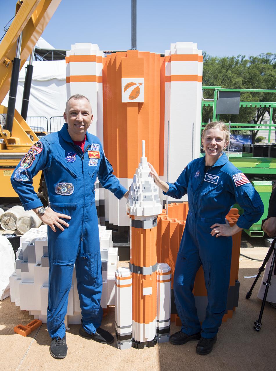
NASA astronaut Randy Bresnik, left, and NASA astronaut candidate, Zena Cardman, pose for a photo with the soon to be 20 ft. model of the Space Launch System (SLS) made out of LEGOs, at the Apollo 11 50th Anniversary celebration on the National Mall, Friday, July 19, 2019 in Washington. Apollo 11 was the first mission to land astronauts on the Moon and launched on July 16, 1969 with astronauts Neil Armstrong, Michael Collins, and Buzz Aldrin. Photo Credit: (NASA/Aubrey Gemignani)
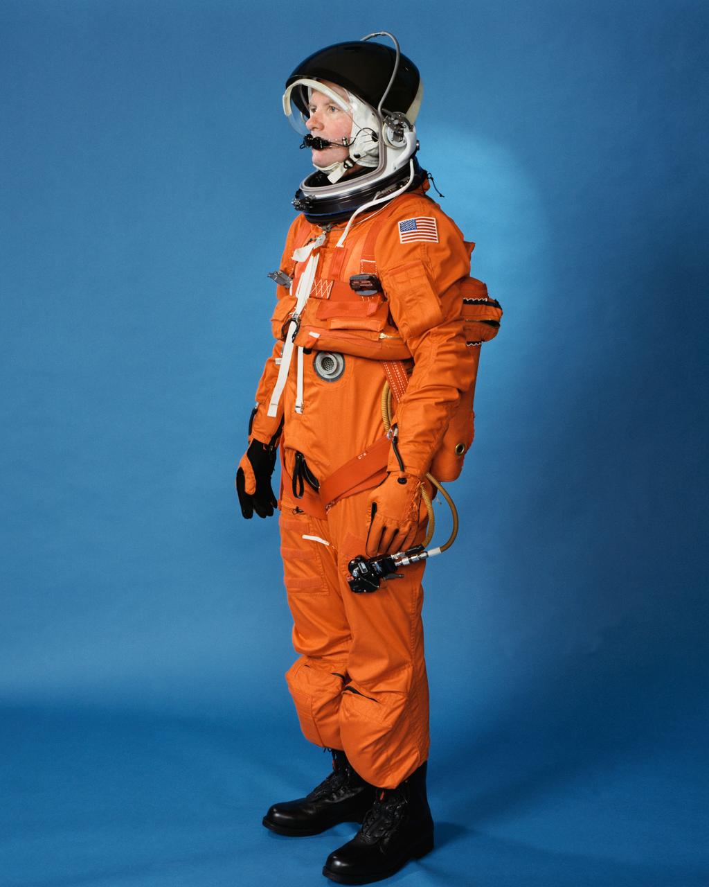
Space shuttle orange launch and entry suit (LES), a partial pressure suit, is modeled by a technician. LES was designed for STS-26, the return to flight mission, and subsequent missions. Included in the crew escape system (CES) package are launch and entry helmet (LEH) with communications carrier (COMM CAP), parachute pack and harness, life raft, life preserver unit (LPU), LES gloves, suit oxygen manifold and valves, boots, and survival gear.
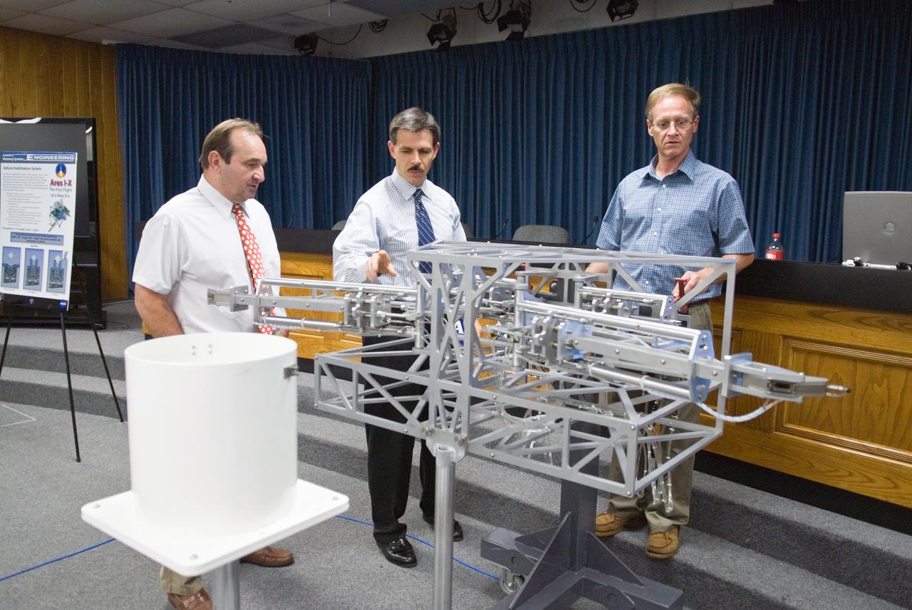
CAPE CANAVERAL, Fla. – In the NASA News Center TV Studio at NASA's Kennedy Space Center in Florida, on view is a 1/12 model of the vehicle stabilization system that will be installed on Launch Pad 39B to hold the Ares I-X rocket for its flight test. Looking at the model are (from left) Roger Lenard, consultant with Lee & Associates, LCC; Jon Cowart, NASA's Ares I-X deputy mission manager; and Eric Mellberg, Ares I-X Vehicle Stabilization Design lead with United Space Alliance Ares I-X is the test vehicle for the Ares I, which is part of the Constellation Program to return men to the moon and beyond. Ares I-X is targeted for launch in August 2009. Photo credit: NASA/Kim Shiflett
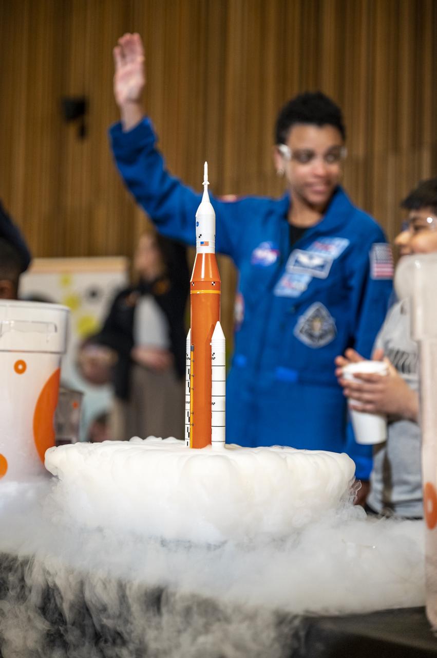
A scale model of NASA’s Space Launch System (SLS) is seen in the foreground during an event with NASA astronauts Jessica Watkins, Robert Hines, and Kjell Lindgren at the Martin Luther King Jr Memorial Library, Thursday, March 30, 2023, in Washington. Lindgren, Hines, and Watkins spent 170 days in space as part of Expeditions 67 and 68 aboard the International Space Station. Photo Credit: (NASA/Keegan Barber)
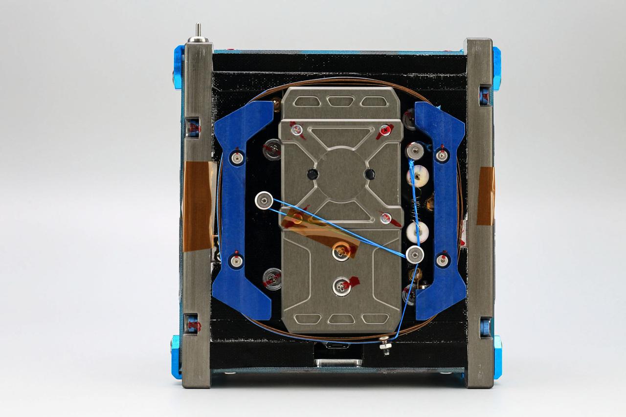
jsc2021e004418 (10/6/2020) --- A pre-flight view of the front side of the RSP-01 Flight Model. The RSP-01 satellite is a 1-Unit (1U) CubeSat that deploys during the JEM Small Satellite Orbital Deployer-16 (J-SSOD-16) micro-satellite deployment mission and is handled by the Japanese Experiment Module Remote Manipulator System (JEMRMS). RSP-01 is developed by Rymansat Spaces and launches to the International Space Station aboard the NG-15 Cygnus Cargo Vehicle. Image Credit: Rymansat Spaces.
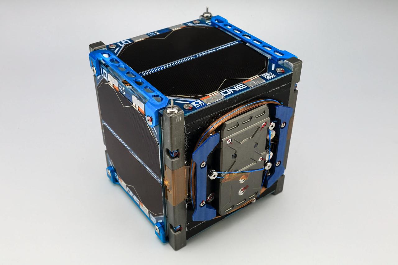
jsc2021e004417 (10/6/2020) --- A pre-flight view of the RSP-01 Flight Model. The RSP-01 satellite is a 1-Unit (1U) CubeSat that deploys during the JEM Small Satellite Orbital Deployer-16 (J-SSOD-16) micro-satellite deployment mission and is handled by the Japanese Experiment Module Remote Manipulator System (JEMRMS). RSP-01 is developed by Rymansat Spaces and launches to the International Space Station aboard the NG-15 Cygnus Cargo Vehicle. Image Credit: Rymansat Spaces.
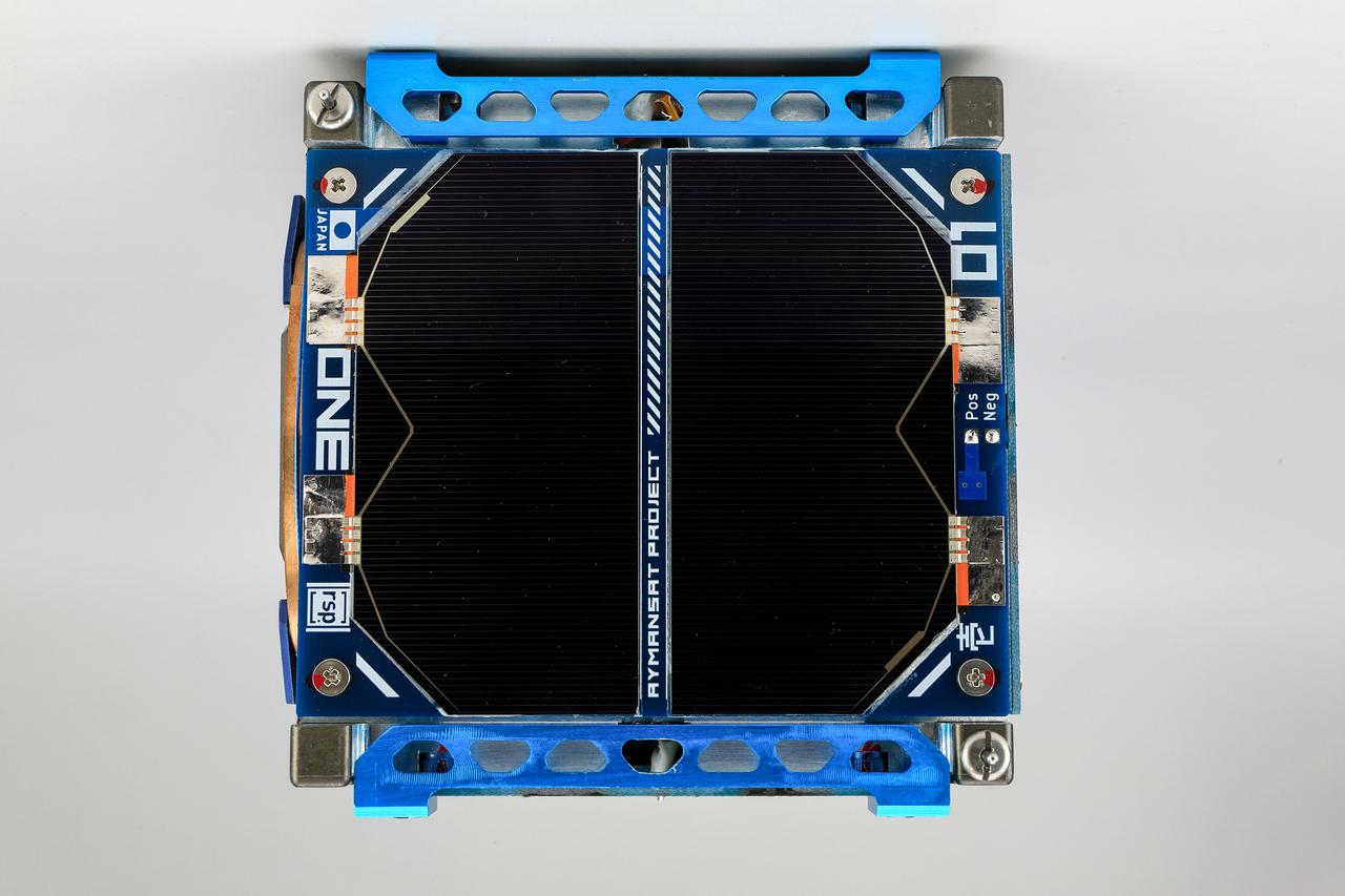
jsc2021e004420 (10/3/2020) --- A pre-flight view of the top of the RSP-01 Flight Model. The RSP-01 satellite is a 1-Unit (1U) CubeSat that deploys during the JEM Small Satellite Orbital Deployer-16 (J-SSOD-16) micro-satellite deployment mission and is handled by the Japanese Experiment Module Remote Manipulator System (JEMRMS). RSP-01 is developed by Rymansat Spaces and launches to the International Space Station aboard the NG-15 Cygnus Cargo Vehicle. Image Credit: Rymansat Spaces.
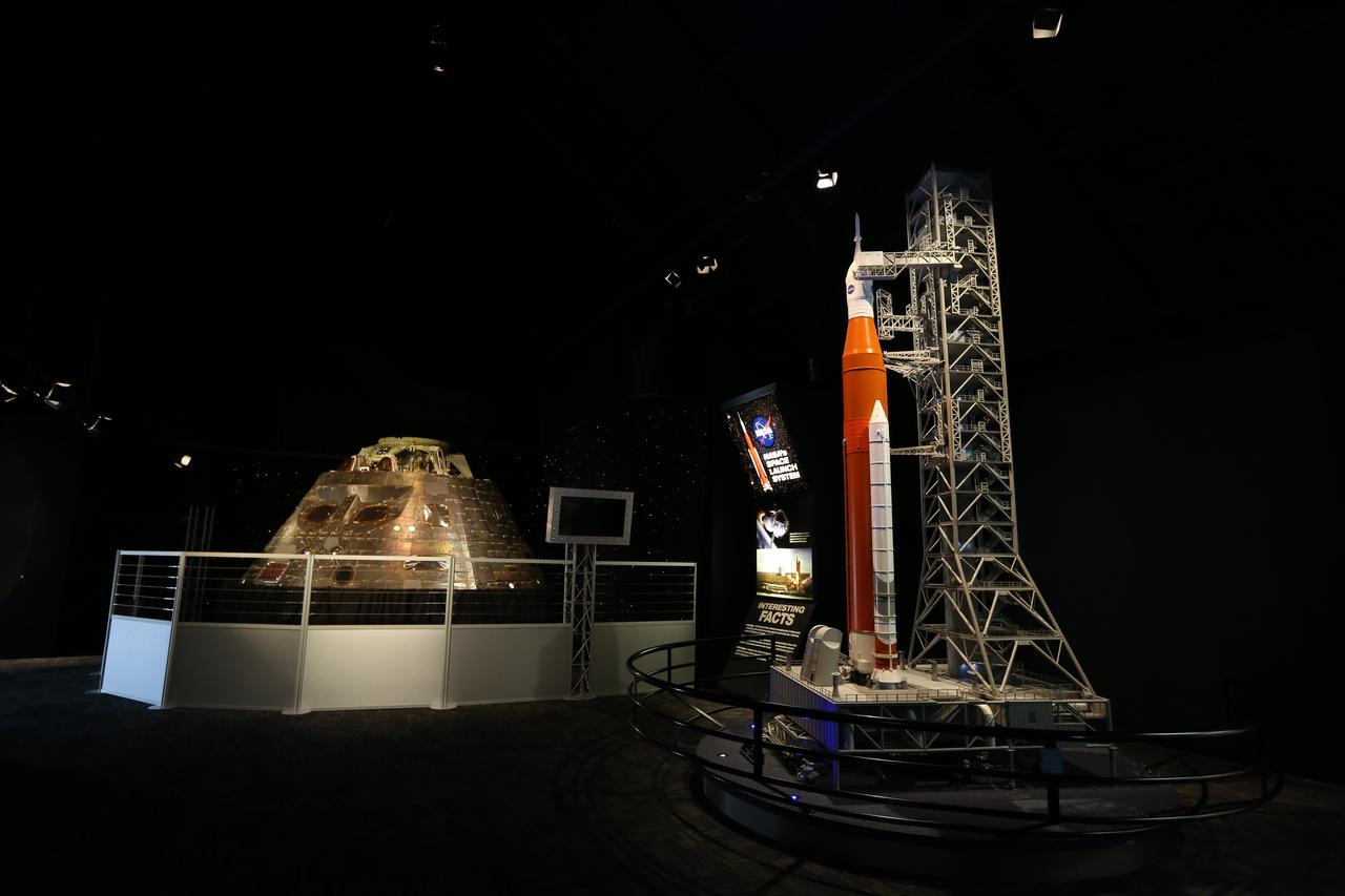
The Orion crew module from Exploration Flight Test 1 (EFT-1) is on display at nearby NASA Kennedy Space Center Visitor Complex in Florida. The crew module is part of the NASA Now exhibit in the IMAX Theater. Also in view is a scale model of NASA's Space Launch System rocket and Orion spacecraft on the mobile launcher. The Orion EFT-1 spacecraft launched atop a United Launch Alliance Delta IV rocket Dec. 5, 2014, from Space Launch Complex 37 at Cape Canaveral Air Force Station. The spacecraft built for humans traveled 3,604 miles above Earth and splashed down about 4.5 hours later in the Pacific Ocean.
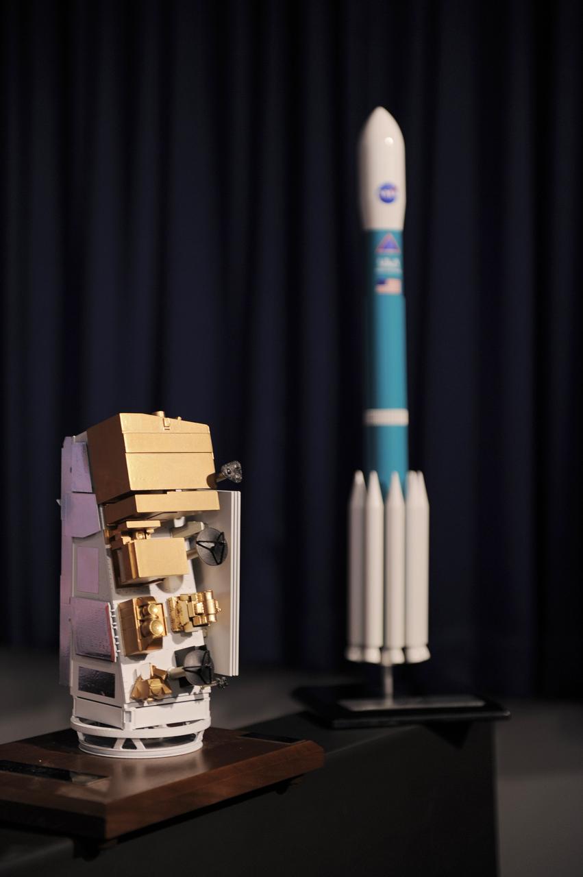
VANDENBERG AIR FORCE BASE, Calif. -- A model of the NASA’s National Polar-orbiting Operational Environmental Satellite System Preparatory Project (NPP) spacecraft and the United Launch Alliance Delta II rocket are displayed during the prelaunch news conference at Vandenberg Air Force Base, Calif. NPP represents a critical first step in building the next-generation of Earth-observing satellites. NPP will carry the first of the new sensors developed for this satellite fleet, now known as the Joint Polar Satellite System (JPSS), to be launched in 2016. NPP is the bridge between NASA's Earth Observing System (EOS) satellites and the forthcoming series of JPSS satellites. The mission will test key technologies and instruments for the JPSS missions. NPP is targeted to launch Oct. 28 from Space Launch Complex-2 aboard a United Launch Alliance Delta II rocket. For more information, visit http://www.nasa.gov/NPP. Photo credit: NASA/VAFB
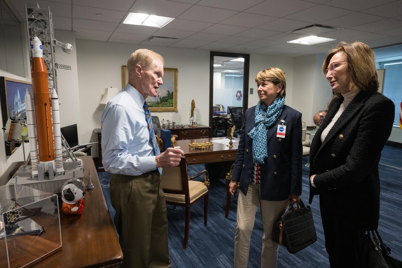
NASA Administrator Bill Nelson shows Monaco’s Minister of Foreign Affairs and Cooperation, Isabelle Berro-Amadeï, left, and Ambassador of the Principality of Monaco to the United States and Canada, the Honorable Maguy Maccario Doyle, right, a model of the Space Launch System (SLS), Thursday, June 22, 2023 at the Mary W. Jackson NASA Headquarters building in Washington. Photo Credit: (NASA/Aubrey Gemignani)
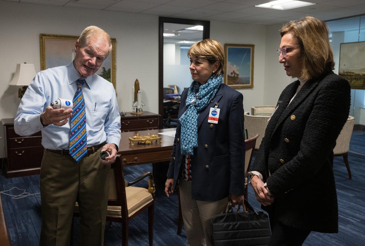
NASA Administrator Bill Nelson shows Monaco’s Minister of Foreign Affairs and Cooperation, Isabelle Berro-Amadeï, left, and Ambassador of the Principality of Monaco to the United States and Canada, the Honorable Maguy Maccario Doyle, right, a model of the Space Launch System (SLS), Thursday, June 22, 2023 at the Mary W. Jackson NASA Headquarters building in Washington. Photo Credit: (NASA/Aubrey Gemignani)
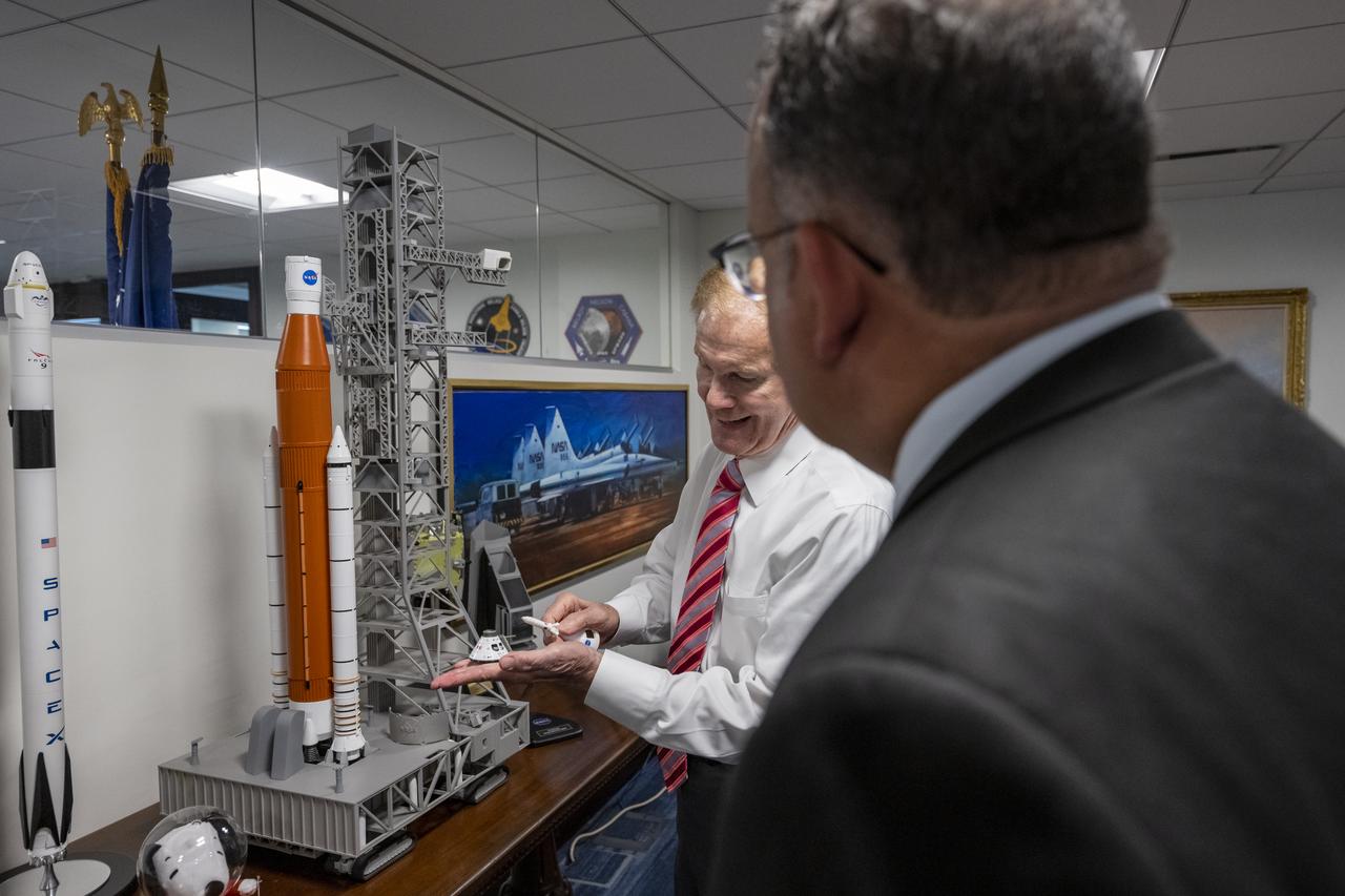
NASA Administrator Bill Nelson, left, shows Secretary of Education Miguel Cardona, right, a model of NASA’s Space Launch System (SLS) and Orion capsule prior to a memorandum of understanding (MOU) signing ceremony, Wednesday, May 24, 2023, at the Mary W. Jackson NASA Headquarters building in Washington. The NASA and Department of Education MOU is focused on strengthening the collaboration between the two agencies, including efforts that advance STEM education across the nation. Photo Credit: (NASA/Keegan Barber)