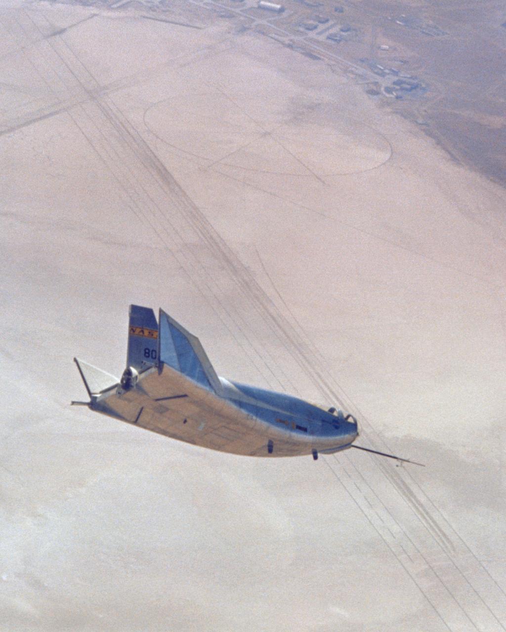
This photo shows the HL-10 in flight, turning to line up with lakebed runway 18. The pilot for this flight, the 29th of the HL-10 series, was Bill Dana. The HL-10 reached a peak altitude of 64,590 feet and a top speed of Mach 1.59 on this particular flight.
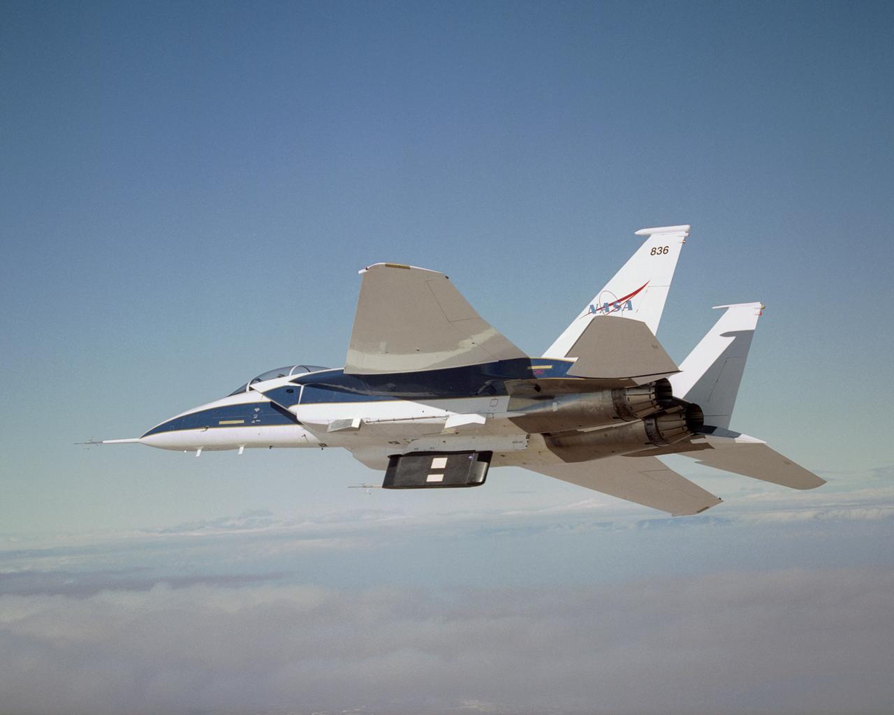
NASA's F-15B research testbed jet from the NASA Dryden Flight Research Center flew in the supersonic shockwave of a Northrop Grumman Corp. modified F-5E in support of the Shaped Sonic Boom Demonstration (SSBD) project, which is part of the DARPA's Quiet Supersonic Platform (QSP) program.
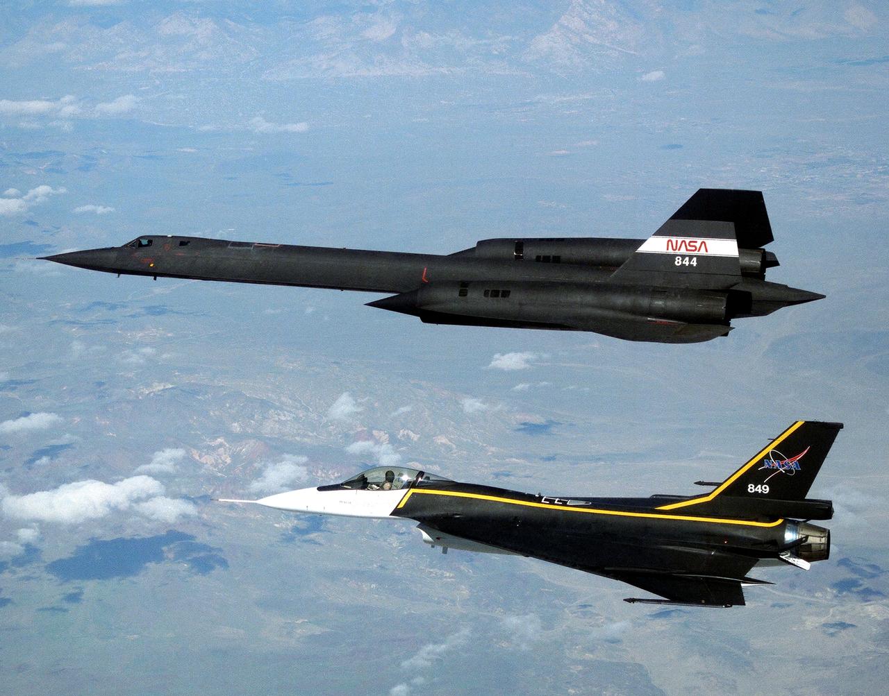
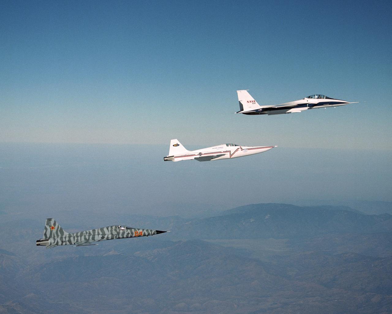
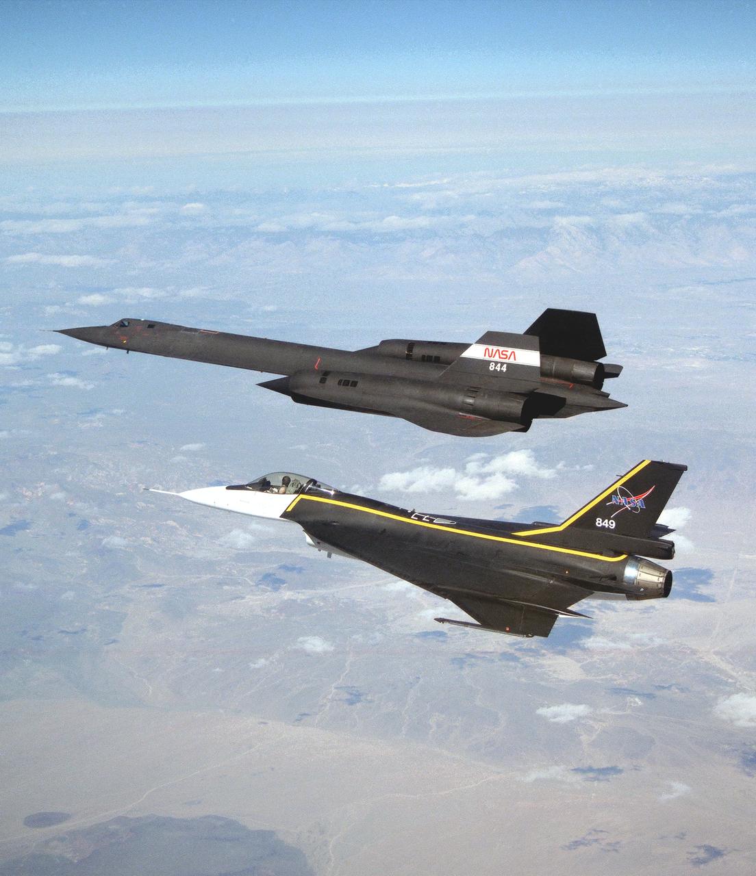
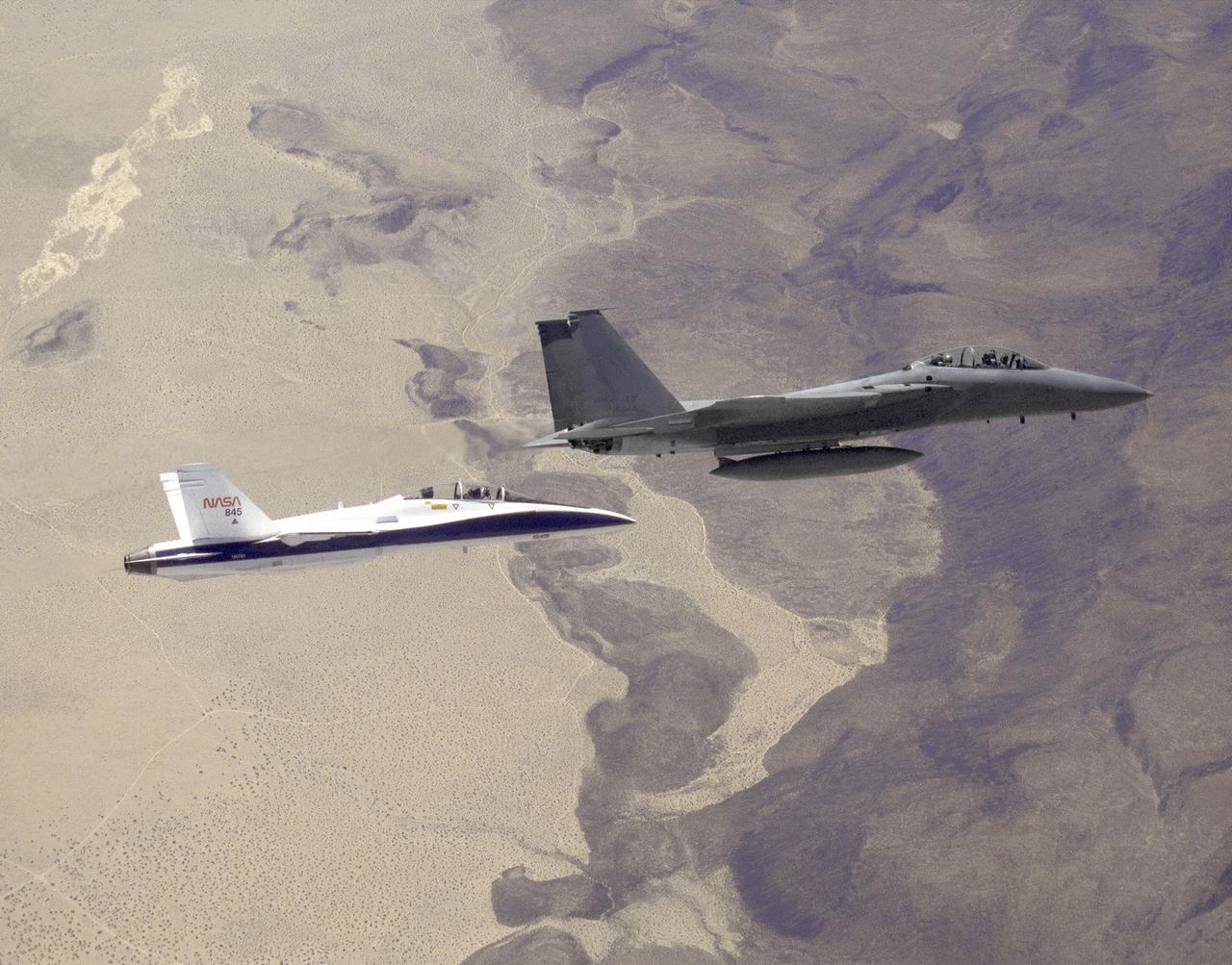
The single-seat F-16XL, NASA 849, joins up with an SR-71A, NASA 844, as crews set up for one of the flights in the recent sonic boom research program conducted by the Dryden Flight Research Center, Edwards, California. During the missions, the F-16XL probed the shockwaves generated by the SR-71, while at lower altitudes sensors on an F-18 and on a YO-3A, and also on the ground, recorded data from the same shockwave.
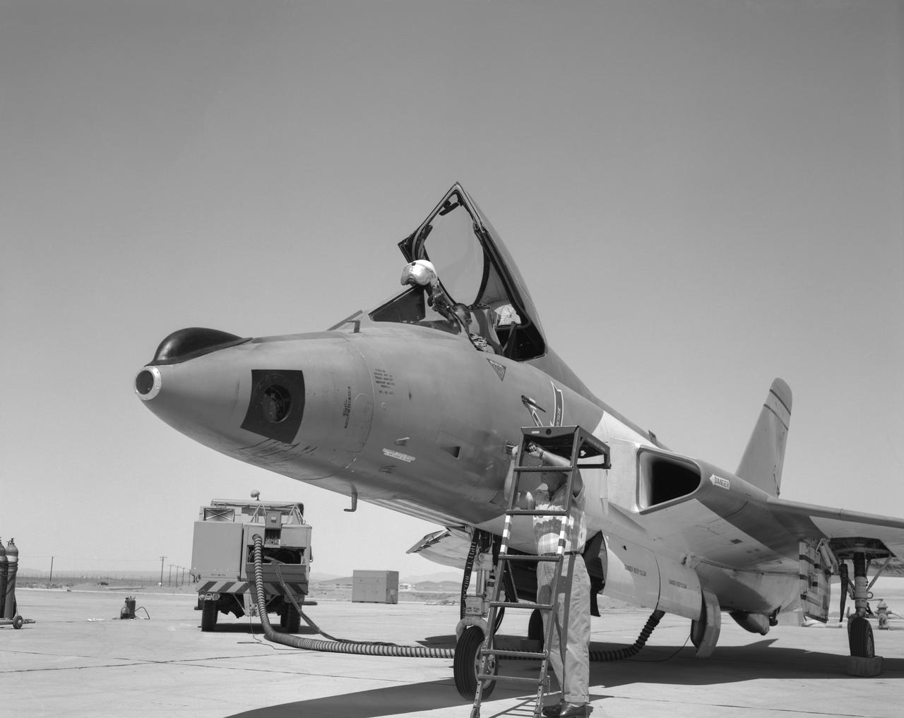
F5D Skylancer with camera installation in nose.
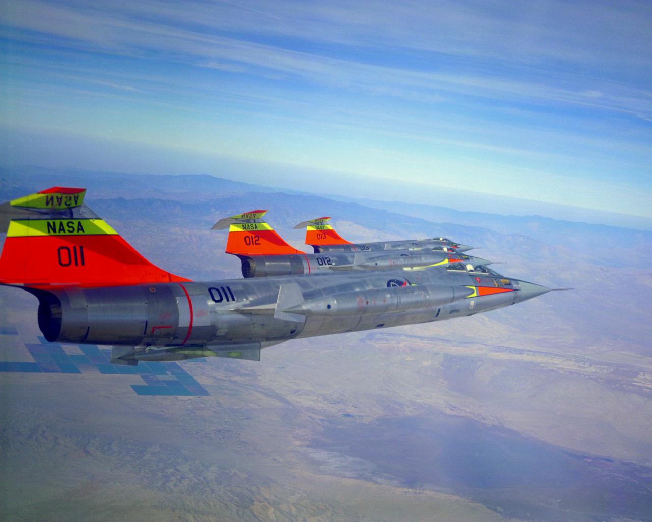
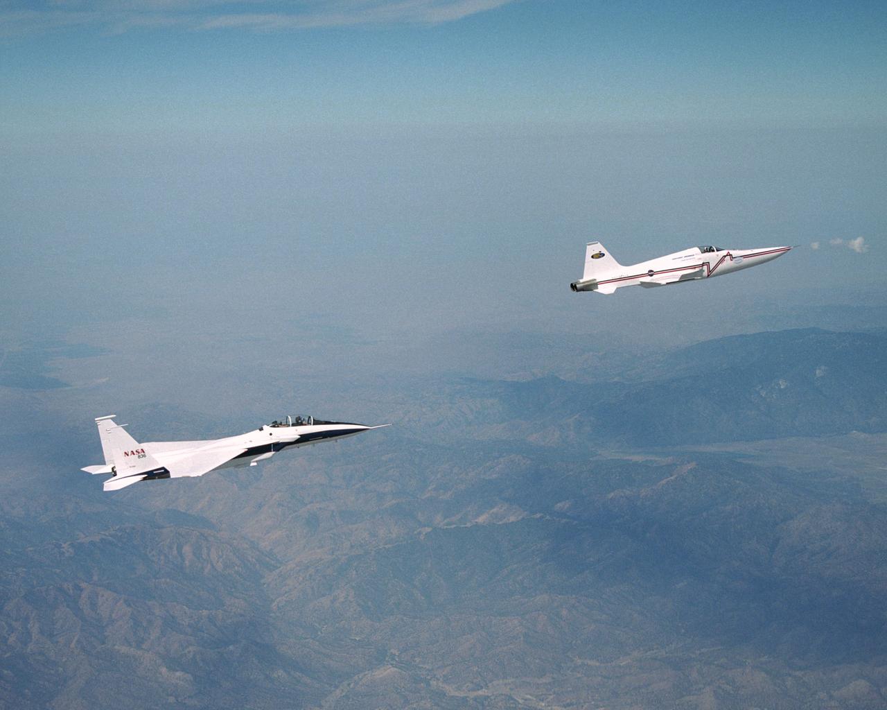
All three NASA F-104N's fly in formation. Aircraft numbers 011, 012 and 013. These would be changed to 811, 812 and 813 in 1965. Pilots are Bruce Peterson in 011, Milt Thompson in 012 and Joe Walker in 013. October 24, 1963
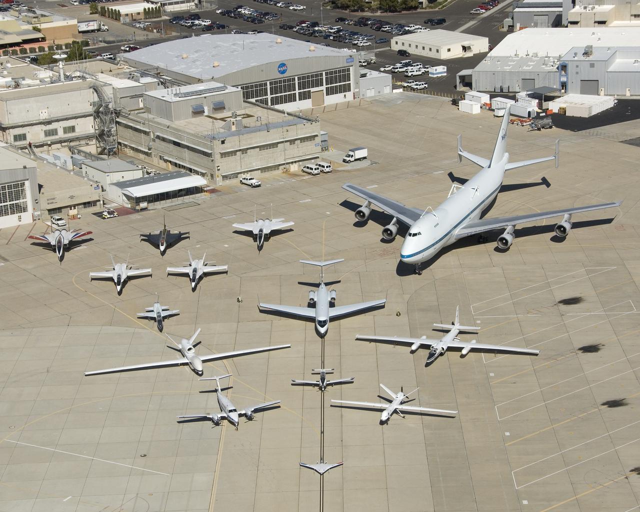
Dryden Flight Research Center - aircraft fleet on ramp
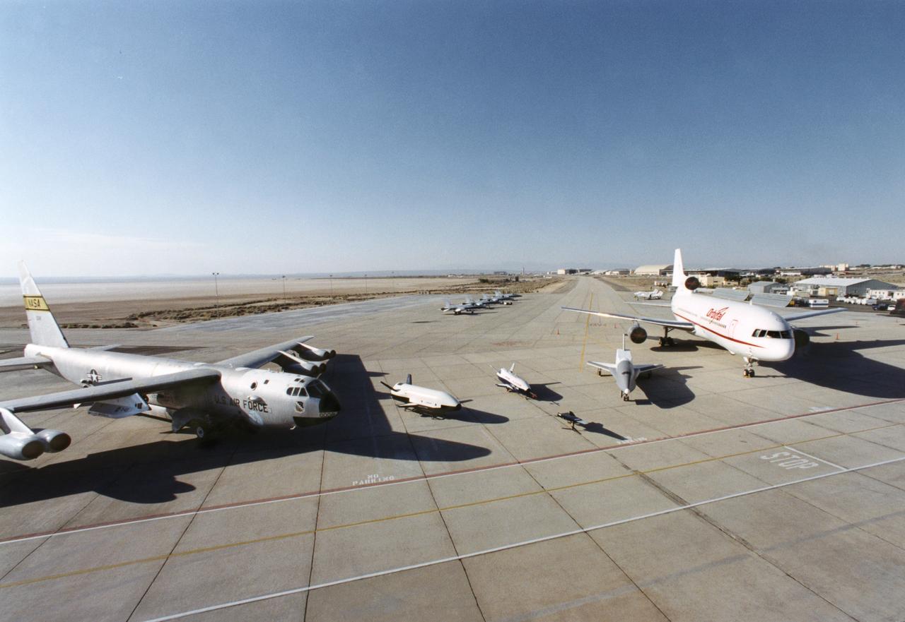
Aerospace industry representatives view actual and mock-up versions of 'X-Planes' intended to enhance access to space during a technical exposition on June 22, 2000 at Dryden Flight Research Center, Edwards, California. From left to right: NASA's B-52 launch aircraft, in service with NASA from 1959 to 2004; a neutral-buoyancy model of the Boeing's X-37; the Boeing X-40A behind the MicroCraft X-43 mock-up; Orbital Science's X-34 and the modified Lockheed L-1011 airliner that was intended to launch the X-34. These X-vehicles are part of NASA's Access to Space plan intended to bring new technologies to bear in an effort to dramatically lower the cost of putting payloads in space, and near-space environments. The June 22, 2000 NASA Reusable Launch Vehicle (RLV) Technology Exposition included presentations on the history, present, and future of NASA's RLV program. Special Sessions for industry representatives highlighted the X-37 project and its related technologies. The X-37 project is managed by NASA's Marshall Space Flight Center, Huntsville, Alabama.
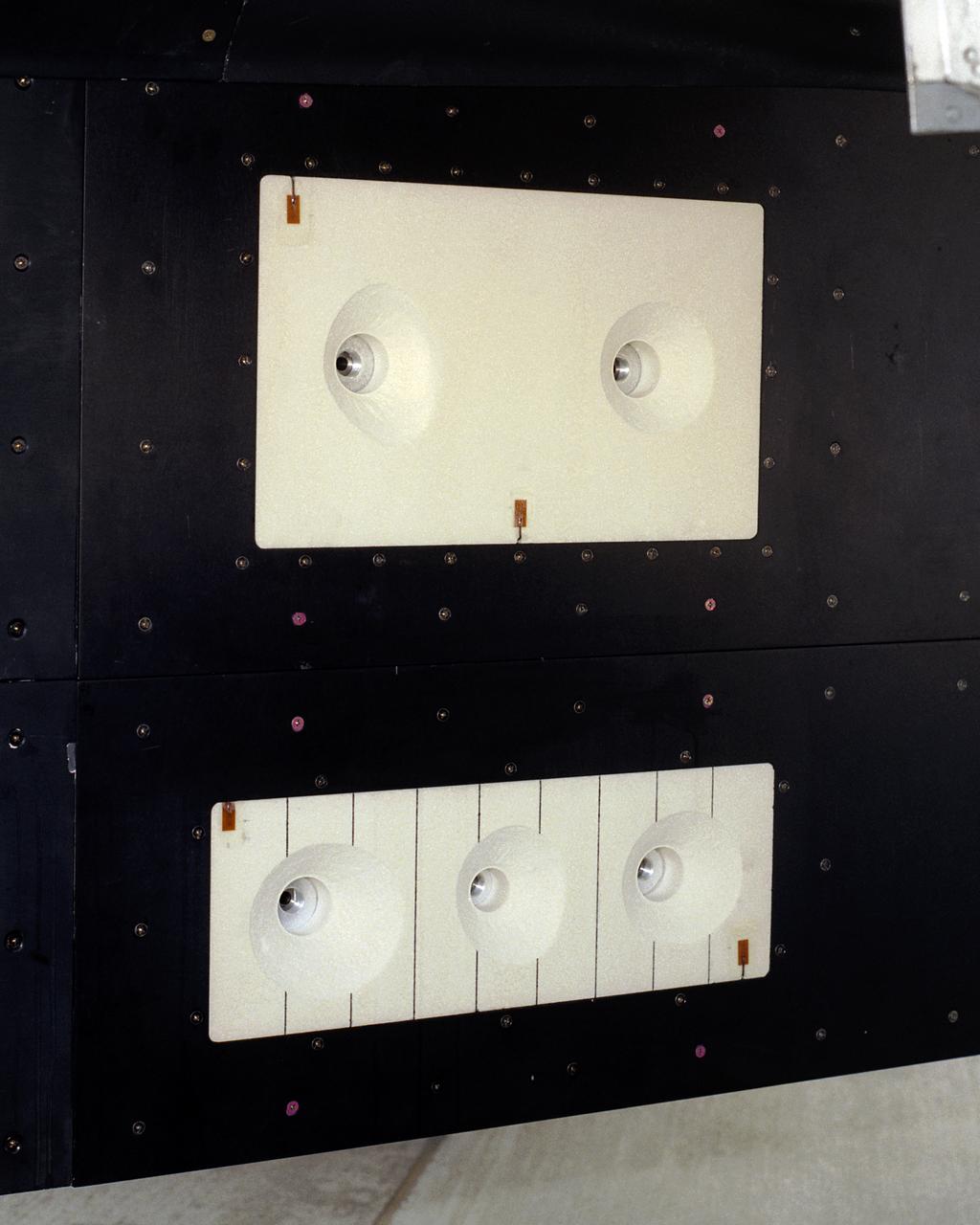
A close-up of the panels on the F-15B's flight test fixture shows five divots of TPS foam were successfully ejected during the LIFT experiment flight #2, the first flight with TPS foam.
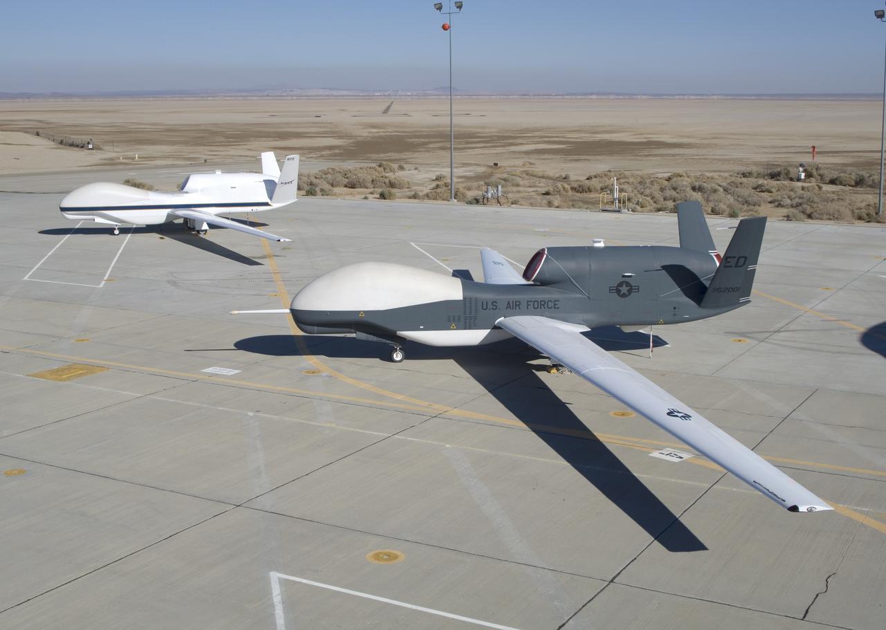
NASA's two Global Hawks, one sporting a NASA paint scheme, the other in its prior Air Force livery, are shown on the ramp at the Dryden Flight Research Center.
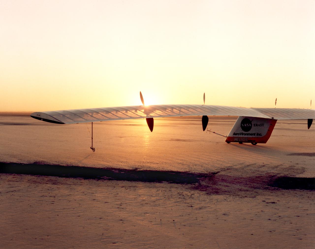
Helios Prototype on lakebed prior to first battery-powered flight
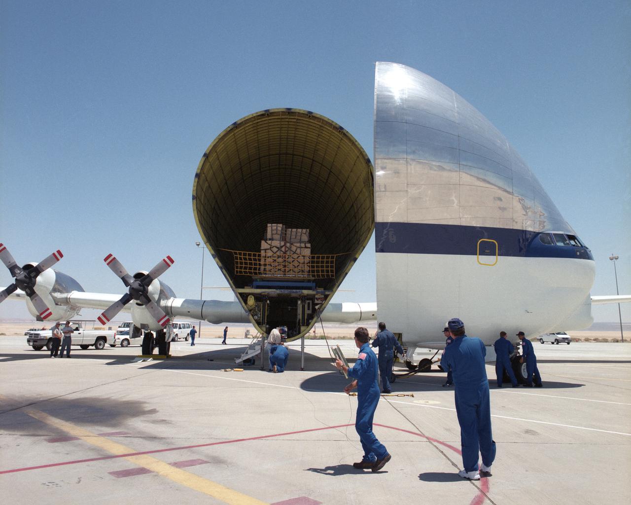
Members of the flight and ground crews prepare to unload equipment from NASA's B377SGT Super Guppy Turbine cargo aircraft on the ramp at NASA's Dryden Flight Research Center at Edwards Air Force Base, Calif. The outsize cargo plane had delivered the latest version of the X-38 flight test vehicle to NASA Dryden when this photo was taken on June 11, 2000.
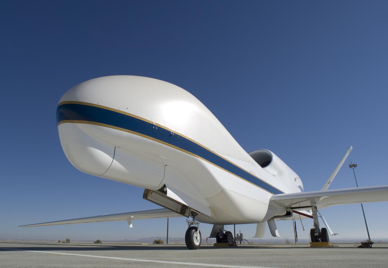
One of NASA's Global Hawk unmanned science aircraft displays its bulbous nose while parked on the ramp at NASA's Dryden Flight Research Center, Edwards, Calif.
A post-flight inspection of the panels on the F-15B's flight test fixture shows five divots of TPS foam were successfully ejected during the LIFT experiment flight #2, the first flight with TPS foam.
All six divots of thermal insulation foam have been ejected from the flight test fixture on NASA's F-15B testbed as it returns from a LIFT experiment flight.
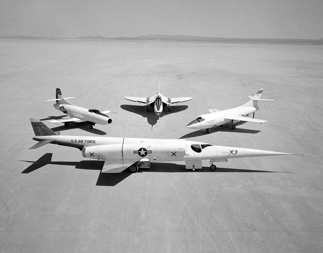
A group picture of Douglas Airplanes, taken for a photographic promotion in 1954, at what is now known as the Dryden Flight Research Center at Edwards Air Force Base, California. The photo includes the X-3 (in front--Air Force serial number 49-2892) then clockwise D-558-I, XF4D-1 (a Navy jet fighter prototype not flown by the NACA), and the first D-558-II (NACA tail number 143, Navy serial number 37973), which was flown only once by the NACA.
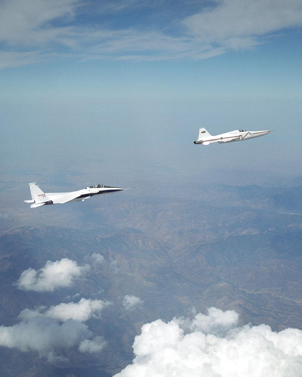
NASA's F-15B research testbed jet from NASA's Dryden Flight Research Center flew in the supersonic shockwave of a Northrop Grumman Corp. modified U.S. Navy F-5E jet in support of the Shaped Sonic Boom Demonstration (SSBD) project, which is part of the DARPA's Quiet Supersonic Platform (QSP) program. The project is an effort to lessen sonic booms. During the recent demonstration, the F-15B flew behind the modified F-5E sonic boom demonstrator aircraft in order to measure the aircraft's sonic boom characteristics. Flying behind and below the F-5E, and using its specially-instrumented nose boom, the F-15B recorded many shockwave patterns from the F-5E at various distances and orientations from the aircraft.

YF-104A (Serial # 55-2961) on Rogers Dry Lake at Edwards AFB.
NASA Dryden Flight Research Center's F-18B Systems Research Aircraft on an External Vision System project flight.

NASA research pilot Bill Dana stands in front of the HL-10 Lifting Body following his first glide flight on April 25, 1969. Dana later retired as Chief Engineer at NASA's Dryden Flight Research Center, (called the NASA Flight Research Center in 1969). Prior to his lifting body assignment, Dana flew the X-15 research airplane. He flew the rocket-powered aircraft 16 times, reaching a top speed of 3,897 miles per hour and a peak altitude of 310,000 feet (almost 59 miles high).
During the final phase of tests with the HARV, Dryden technicians installed nose strakes, which were panels that fitted flush against the sides of the forward nose. When the HARV was at a high alpha, the aerodynamics of the nose caused a loss of directional stability. Extending one or both of the strakes results in strong side forces that, in turn, generated yaw control. This approach, along with the aircraft's Thrust Vectoring Control system, proved to be stability under flight conditions in which conventional surfaces, such as the vertical tails, were ineffective.
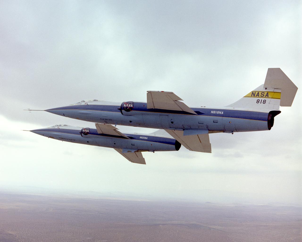
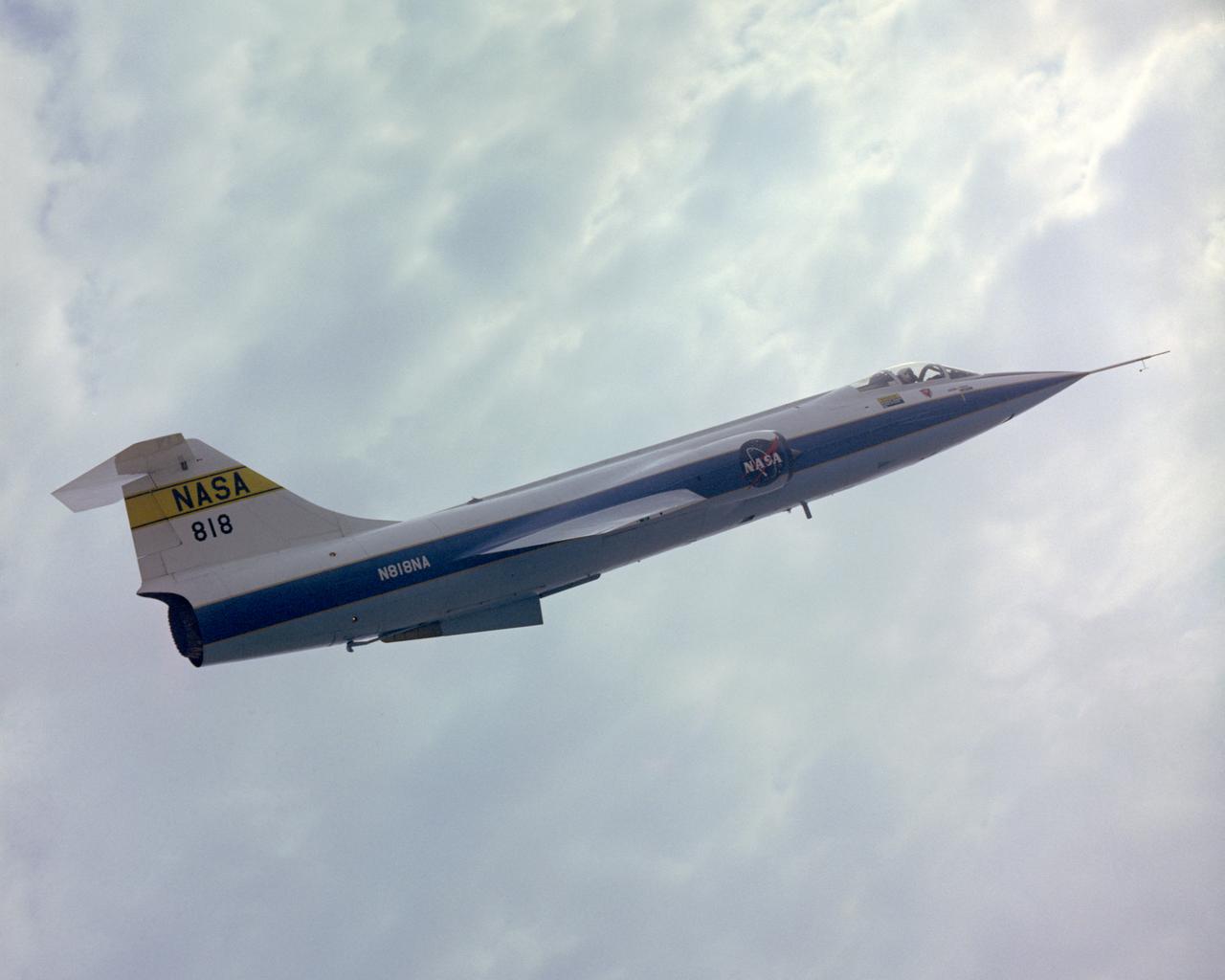
F-104A #818 flown by Einar Enevoldson and F-104A #820 flown by Gary Krier in formation over the Mojave Desert. 4/11/75 NASA DFRC EC76-5140
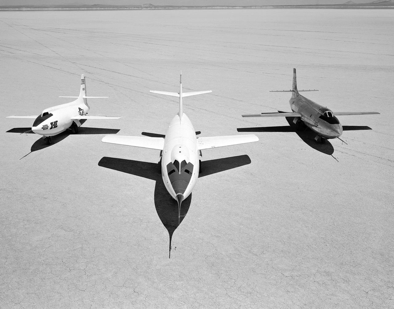
Early NACA research aircraft on the lakebed at the High Speed Research Station in 1955: Left to right: X-1E, D-558-II, X-1B

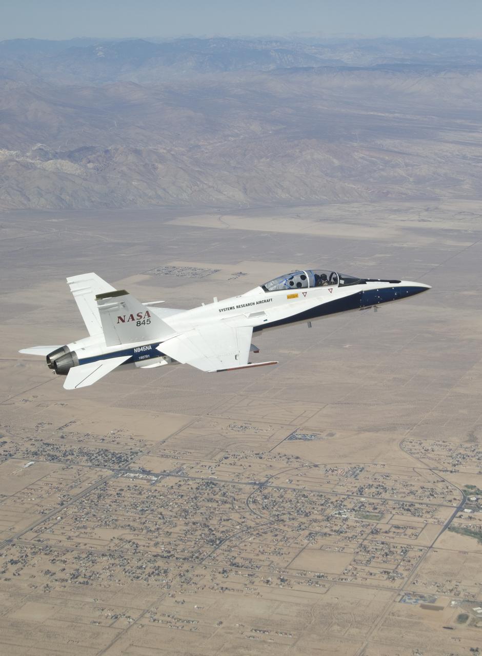
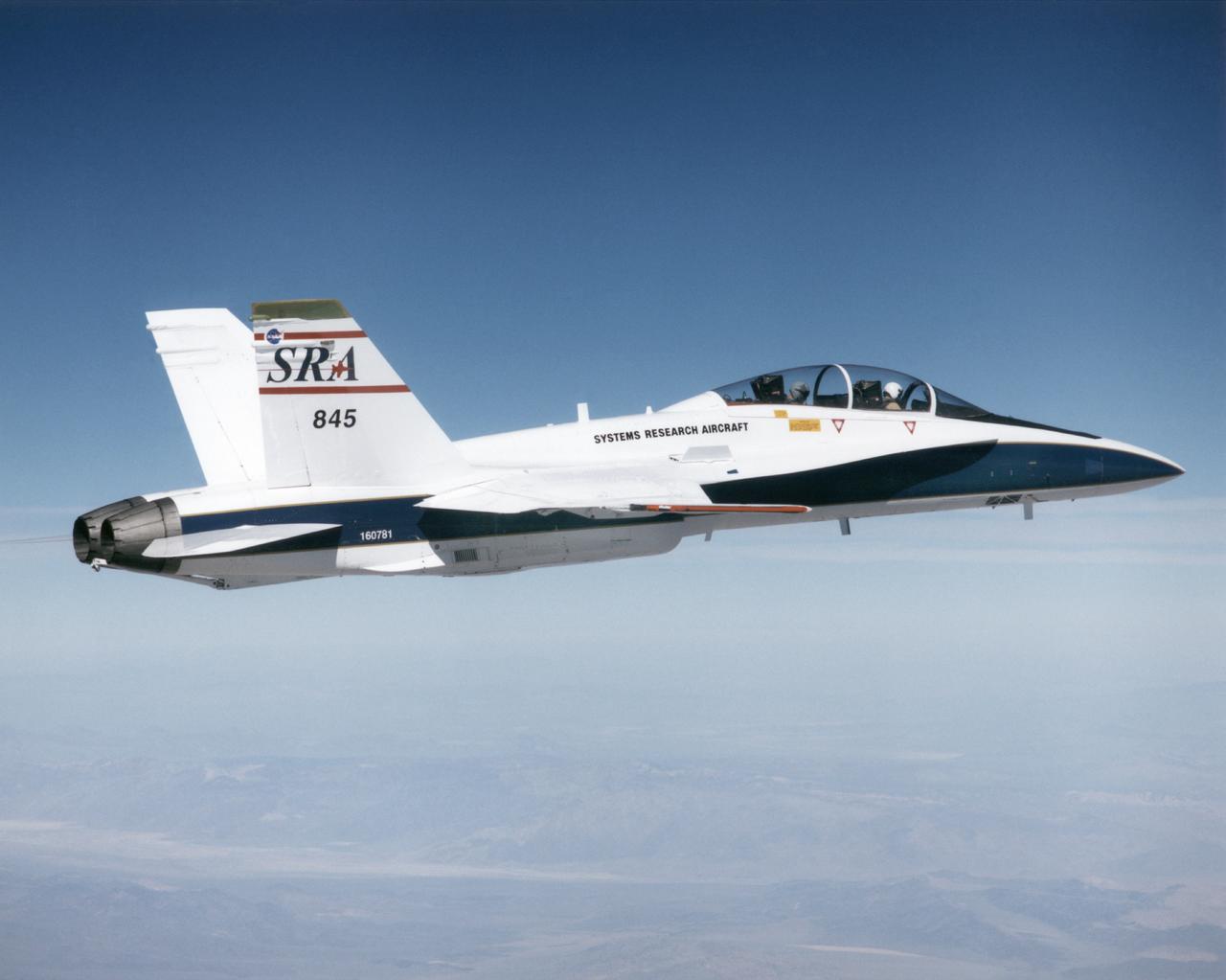
A NASA F/A-18, specially modified to test the newest and most advanced system technologies, on its first research flight on May 21, 1993, at NASA's Dryden Flight Research Facility, Edwards, California. Flown by Dryden in a multi-year, joint NASA/DOD/industry program, the F/A-18 former Navy fighter was modified into a unique Systems Research Aircraft (SRA) to investigate a host of new technologies in the areas of flight controls, airdata sensing and advanced computing. The primary goal of the SRA program was to validate through flight research cutting-edge technologies which could benefit future aircraft and spacecraft by improving efficiency and performance, reducing weight and complexity, with a resultant reduction on development and operational costs.

This view from a NASA Dryden F-18 chase aircraft shows Dryden's highly modified F-15B, tail number 837, which resumed Intelligent Flight Control System (IFCS) project flights on Dec. 6, 2002.
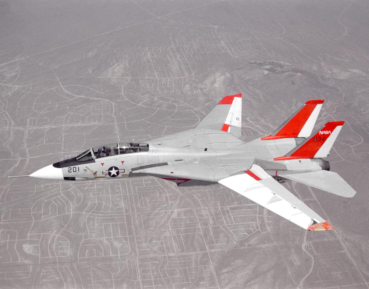
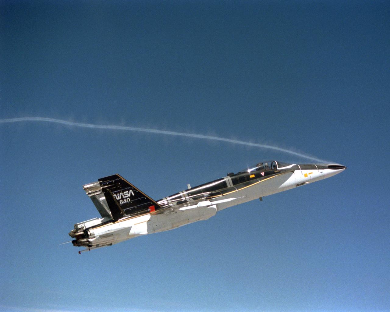
NASA 834, an F-14 Navy Tomcat, seen here in flight, was used at Dryden in 1986 and 1987 in a program known as the Variable-Sweep Transition Flight Experiment (VSTFE). This program explored laminar flow on variable sweep aircraft at high subsonic speeds. An F-14 aircraft was chosen as the carrier vehicle for the VSTFE program primarily because of its variable-sweep capability, Mach and Reynolds number capability, availability, and favorable wing pressure distribution. The variable sweep outer-panels of the F-14 aircraft were modified with natural laminar flow gloves to provide not only smooth surfaces but also airfoils that can produce a wide range of pressure distributions for which transition location can be determined at various flight conditions and sweep angles. Glove I, seen here installed on the upper surface of the left wing, was a "cleanup" or smoothing of the basic F-14 wing, while Glove II was designed to provide specific pressure distributions at Mach 0.7. Laminar flow research continued at Dryden with a research program on the NASA 848 F-16XL, a laminar flow experiment involving a wing-mounted panel with millions of tiny laser cut holes drawing off turbulent boundary layer air with a suction pump.
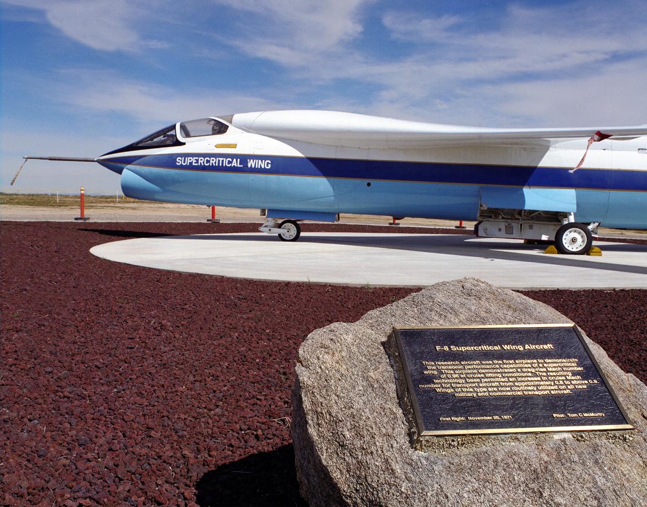
A Vought F-8A Crusader was selected by NASA as the testbed aircraft (designated TF-8A) to install an experimental Supercritical Wing (SCW) in place of the conventional wing. The unique design of the Supercritical Wing reduces the effect of shock waves on the upper surface near Mach 1, which in turn reduces drag. In the photograph the TF-8A Crusader with the Supercritical Wing is shown on static display in front of the NASA Dryden Flight Research Center, Edwards, California. The F-8 SCW aircraft, along with the F-8 Digital Fly-By-Wire aircraft were placed on display on May 27, 1992, at a conference marking the 20th anniversary of the start of the two programs.
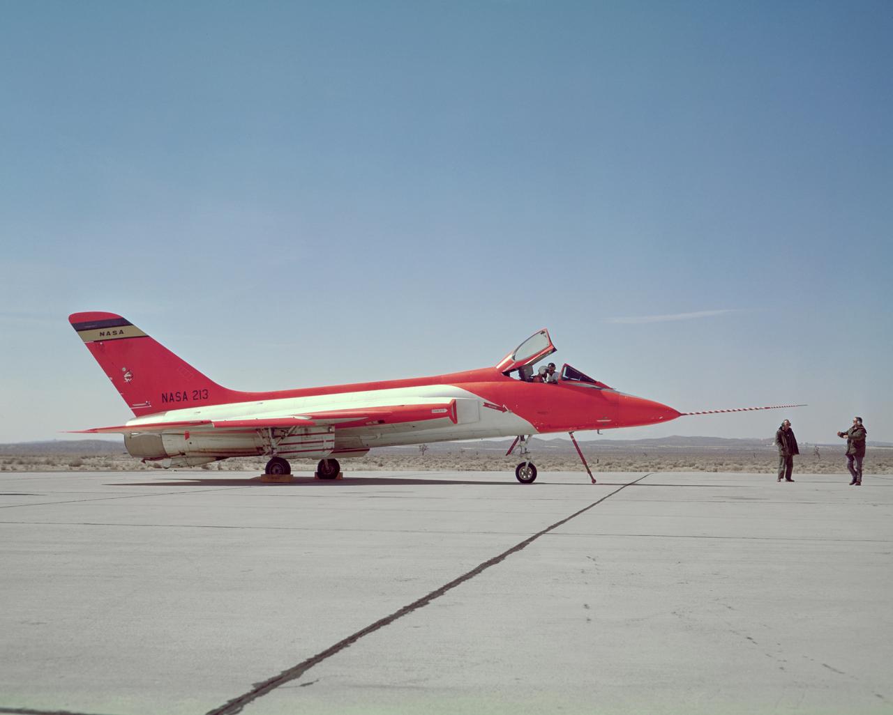
F5D Skylancer taxis in after a mission.
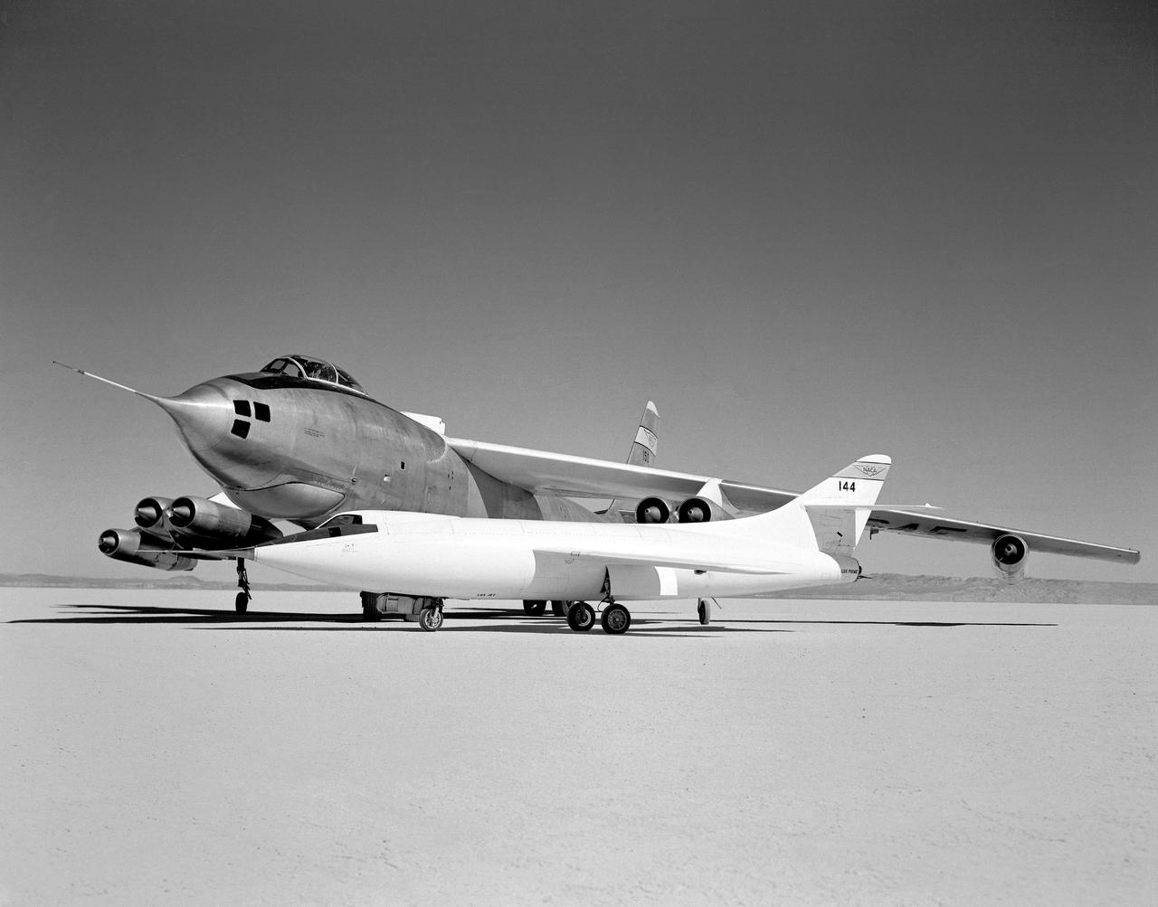
In 1954 this photo of two swept wing airplanes was taken on the ramp of NACA High-Speed Flight Research Station. The Douglas D-558-ll is a research aircraft while the Boeing B-47A Stratojet is a production bomber and very different in size. Both contributed to the studies for swept back wing research.
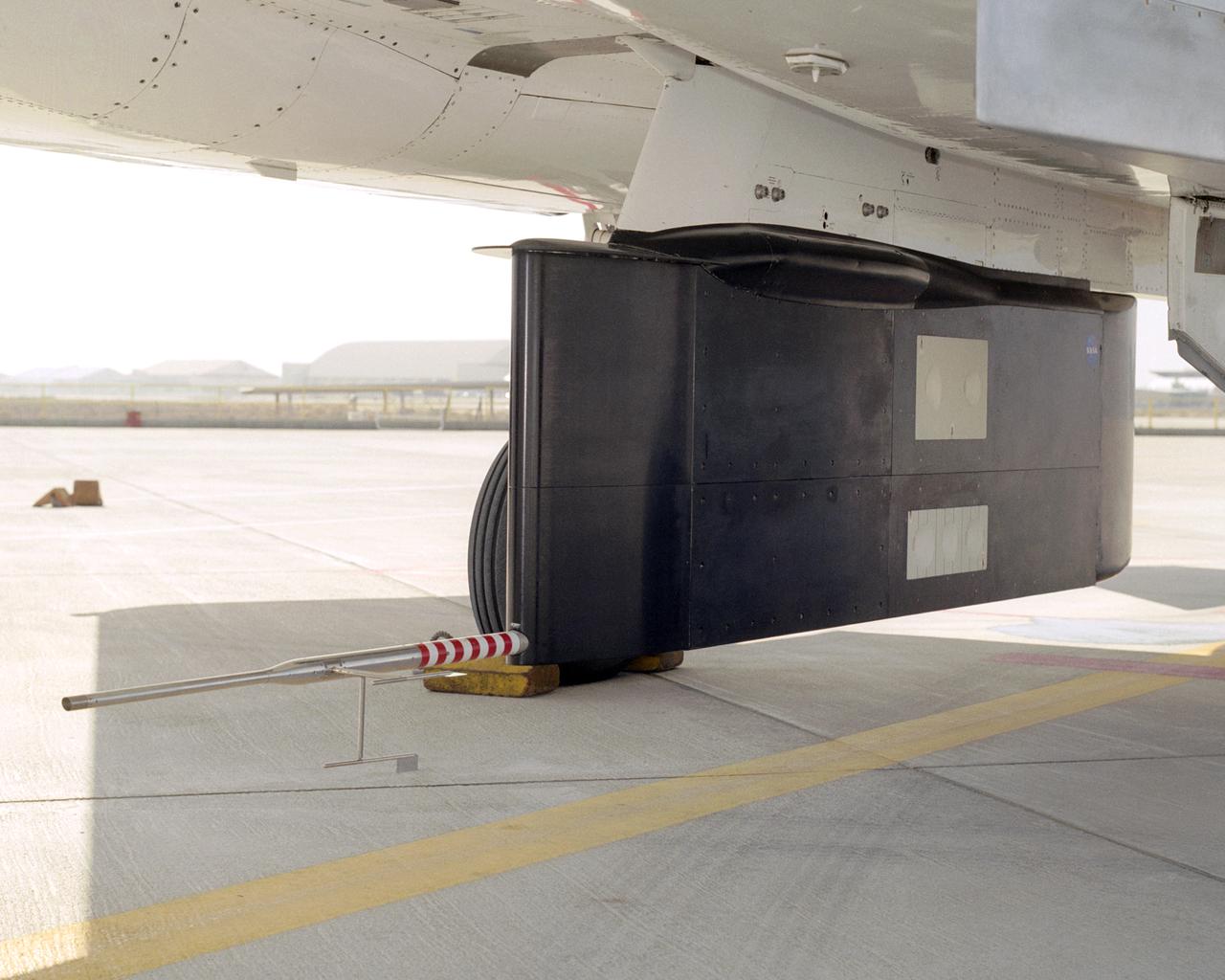
Two panels of Space Shuttle TPS insulation were mounted on the flight test fixture underneath NASA's F-15B during the Lifting Foam Trajectory flight test series.
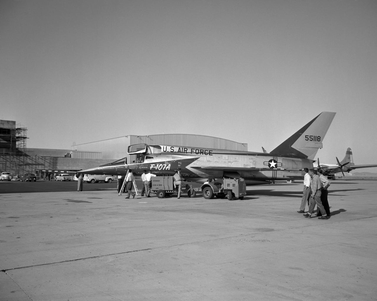
Arrival of first F-107A #118 (later NACA 207) to NASA FRC
In a role-reversal, Northrop Grumman Corp.'s modified F-5E Shaped Sonic Boom Demonstration (SSBD) aircraft flies off the wing of NASA's F-15B Research testbed aircraft. The F-15B, from NASA's Dryden Flight Research Center, flew in the supersonic shockwave of the F-5E as part of the SSBD project. Following the two aircraft is an unmodified U.S. Navy F-5E used for baseline sonic boom measurements.

This photograph shows a modified General Dynamics AFTI/F-111A Aardvark with supercritical mission adaptive wings (MAW) installed. The four dark bands on the right wing are the locations of pressure orifices used to measure surface pressures and shock locations on the MAW. The El Paso Mountains and Red Rock Canyon State Park Califonia, about 30 miles northwest of Edwards Air Force Base, are seen directly in the background. With the phasing out of the TACT program came a renewed effort by the Air Force Flight Dynamics Laboratory to extend supercritical wing technology to a higher level of performance. In the early 1980s the supercritical wing on the F-111A aircraft was replaced with a wing built by Boeing Aircraft Company System called a “mission adaptive wing” (MAW), and a joint NASA and Air Force program called Advanced Fighter Technology Integration (AFTI) was born.
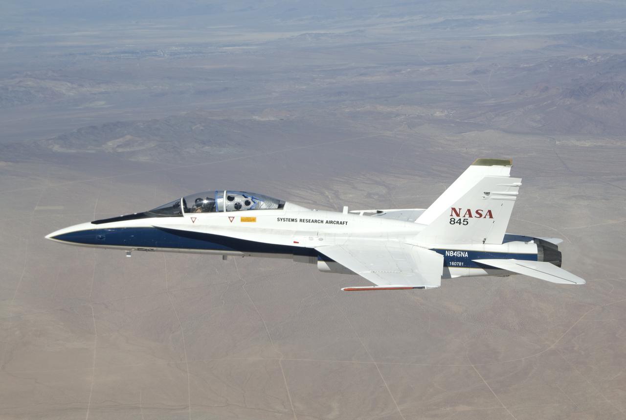
NASA Dryden Flight Research Center's F-18B Systems Research Aircraft on an External Vision System project flight.
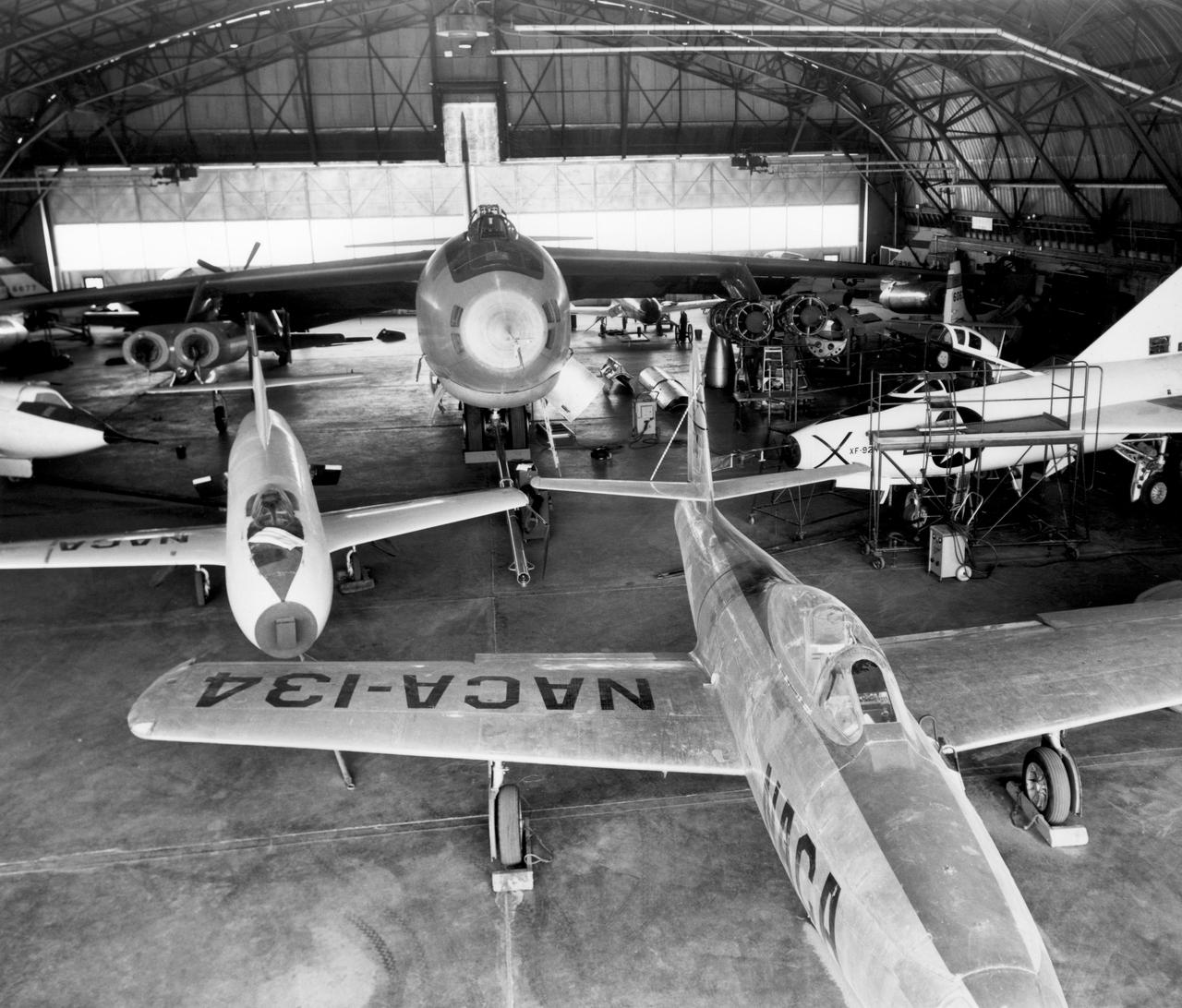
In the center foreground of this 1953 hangar photo is the YF-84A (NACA 134/Air Force 45-59490) used for vortex generator research. It arrived on November 28, 1949, and departed on April 21, 1954. Beside it is the third D-558-1 aircraft (NACA 142/Navy 37972). This aircraft was used for a total of 78 transonic research flights from April 1949 to June 1954. It replaced the second D-558-1, lost in the crash which killed Howard Lilly. Just visible on the left edge is the nose of the first D-558-2 (NACA 143/Navy 37973). Douglas turned the aircraft over to NACA on August 31, 1951, after the contractor had completed its initial test flights. NACA only made a single flight with the aircraft, on September 17, 1956, before the program was cancelled. In the center of the photo is the B-47A (NACA 150/Air Force 49-1900). The B-47 jet bomber, with its thin, swept-back wings, and six podded engines, represented the state of the art in aircraft design in the early 1950s. The aircraft undertook a number of research activities between May 1953 and its 78th and final research flight on November 22, 1957. The tests showed that the aircraft had a buffeting problem at speeds above Mach 0.8. Among the pilots who flew the B-47 were later X-15 pilots Joe Walker, A. Scott Crossfield, John B. McKay, and Neil A. Armstrong. On the right side of the B-47 is NACA's X-1 (Air Force 46-063). The second XS-1 aircraft built, it was fitted with a thicker wing than that on the first aircraft, which had exceeded Mach 1 on October 14, 1947. Flight research by NACA pilots indicated that this thicker wing produced 30 percent more drag at transonic speeds compared to the thinner wing on the first X-1. After a final flight on October 23, 1951, the aircraft was grounded due to the possibility of fatigue failure of the nitrogen spheres used to pressurize the fuel tanks. At the time of this photo, in 1953, the aircraft was in storage. In 1955, the aircraft was extensively modified, becoming the X-1E. In front o
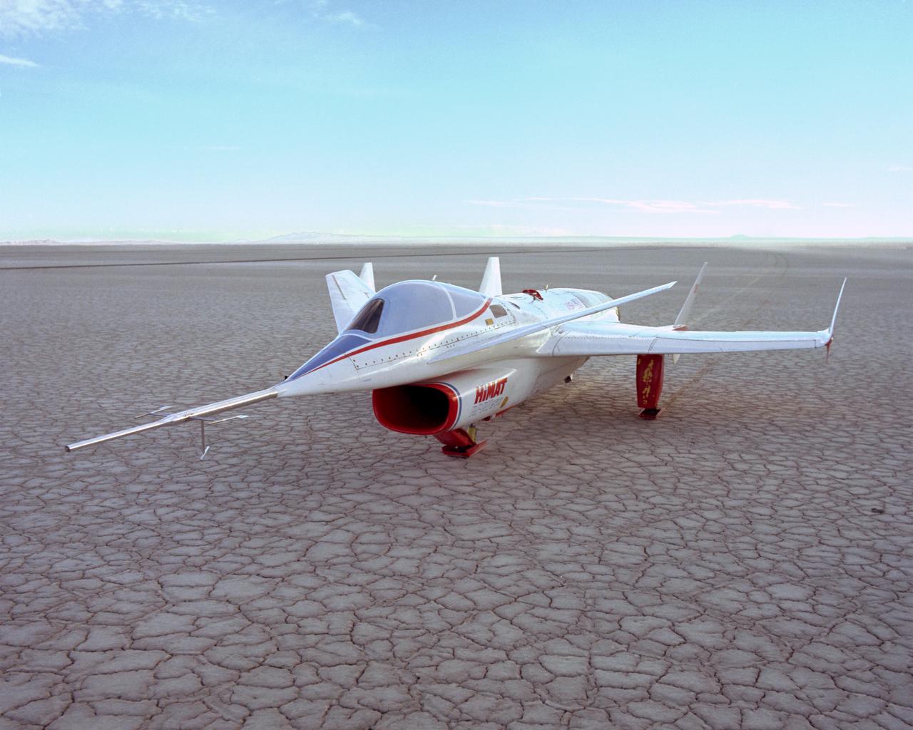
The HiMAT (Highly Maneuverable Aircraft Technology) subscale research vehicle, seen here after landing to conclude a research flight, was flown by the NASA Dryden Flight Research Center, Edwards, California, from mid 1979 to January 1983. The aircraft demonstrated advanced fighter technologies that have been used in the development of many modern high performance military aircraft.

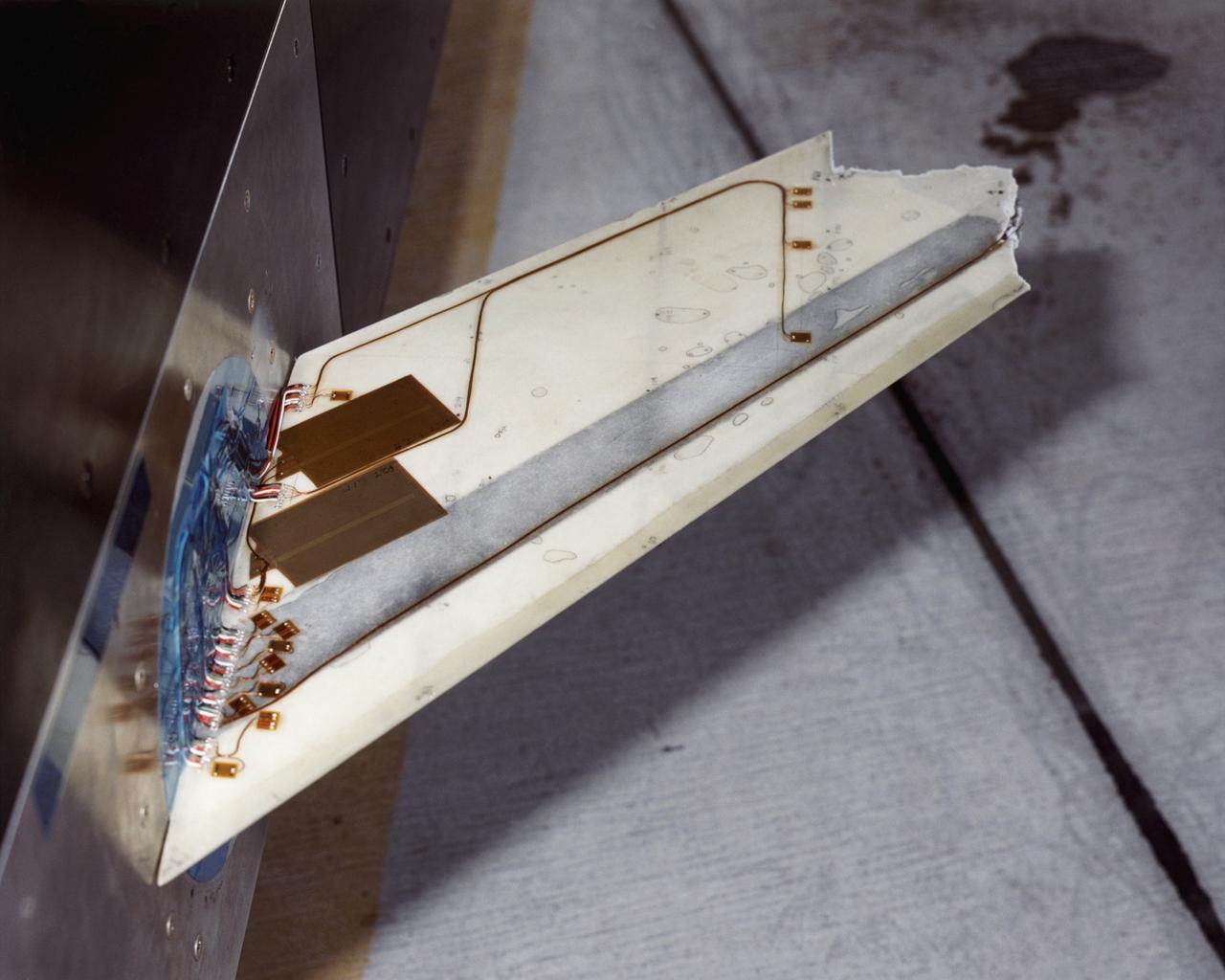
A close up of the Flight Test Fixture II, mounted on the underside of the F-15B Aerodynamic Flight Facility aircraft. The Thermal Protection System (TPS) samples, which included metallic Inconel tiles, soft Advanced Flexible Reusable Surface Insulation tiles, and sealing materials, were attached to the forward-left side position of the test fixture. In-flight video from the aircraft's on-board video system, as well as chase aircraft photos and video footage, documented the condition of the TPS during flights. Surface pressures over the TPS was measured by thermocouples contained in instrumentation "islands," to document shear and shock loads.
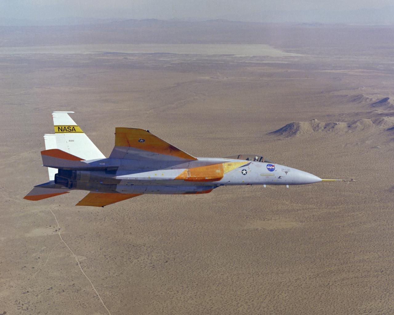
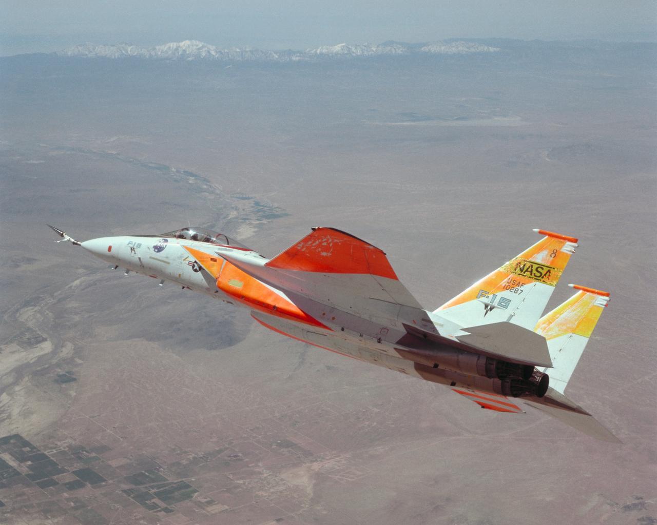
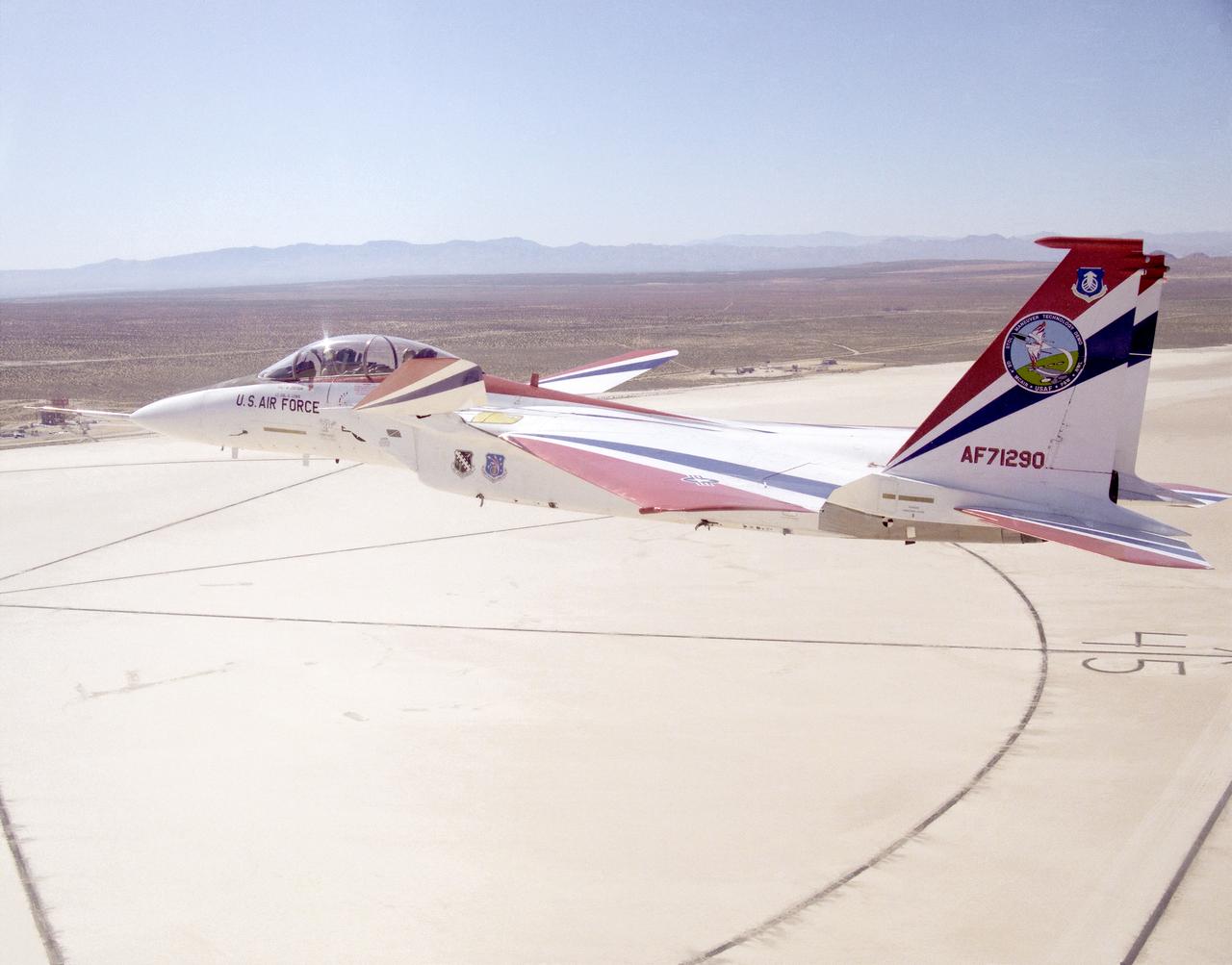
The number two F-15A (Serial #71-0281) was obtained by NASA from the U.S. Air Force in 1976 and was used for more than 25 advanced research projects involving aerodynamics, performance, propulsion control, control integration, instrumentation development, human factors, and flight test techniques. Included in these projects was its role as a testbed to evaluate aerodynamic pressures on Space Shuttle thermal protection tiles at specific altitudes and speeds.
An in-flight photo of the NASA F-15A with a 10 degree cone to collect aerodynamic information to calibrate data from wind tunnels.
F-15B ACTIVE in flight over lakebed
F-104A #818 flown by Einar Enevoldson. 4/11/75 NASA DFRC EC76-5079 NASA Photo by Bob Rhine
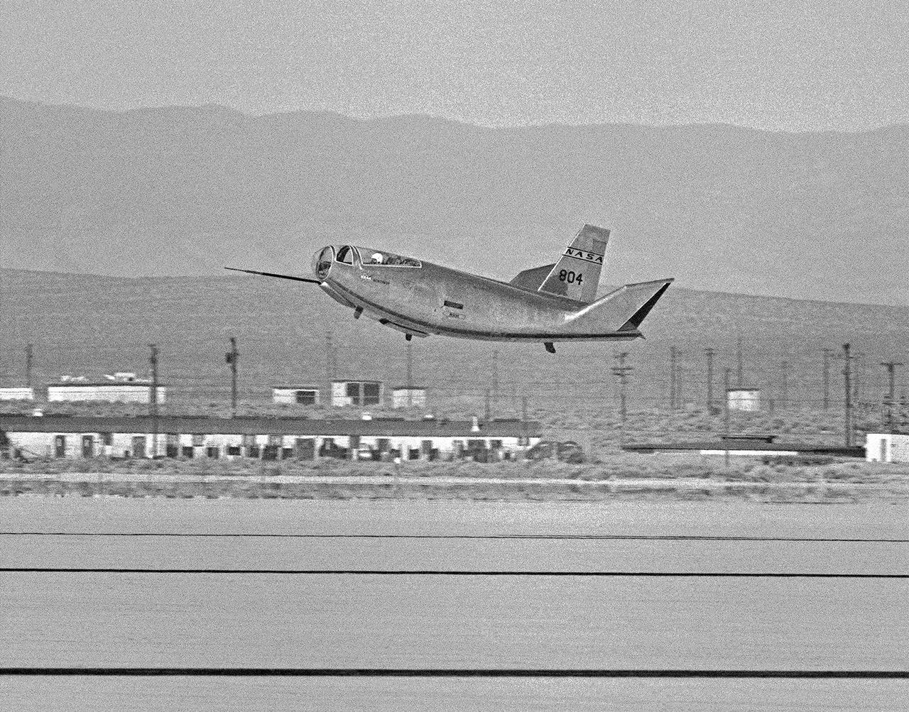
The HL-10 Lifting Body completes its first research flight with a landing on Rogers Dry Lake at Edwards AFB, California, on December 22, 1966. The HL-10 suffered from buffeting and poor control during the flight. Pilot Bruce Peterson was able to make a successful landing despite the severe problems. These were traced to airflow separation from the fins. As a result, the fins were no longer able to stabilize the vehicle. A small reshaping of the fins' leading edges cured the airflow separation, but it was not until March 15, 1968, that the second HL-10 flight occurred.
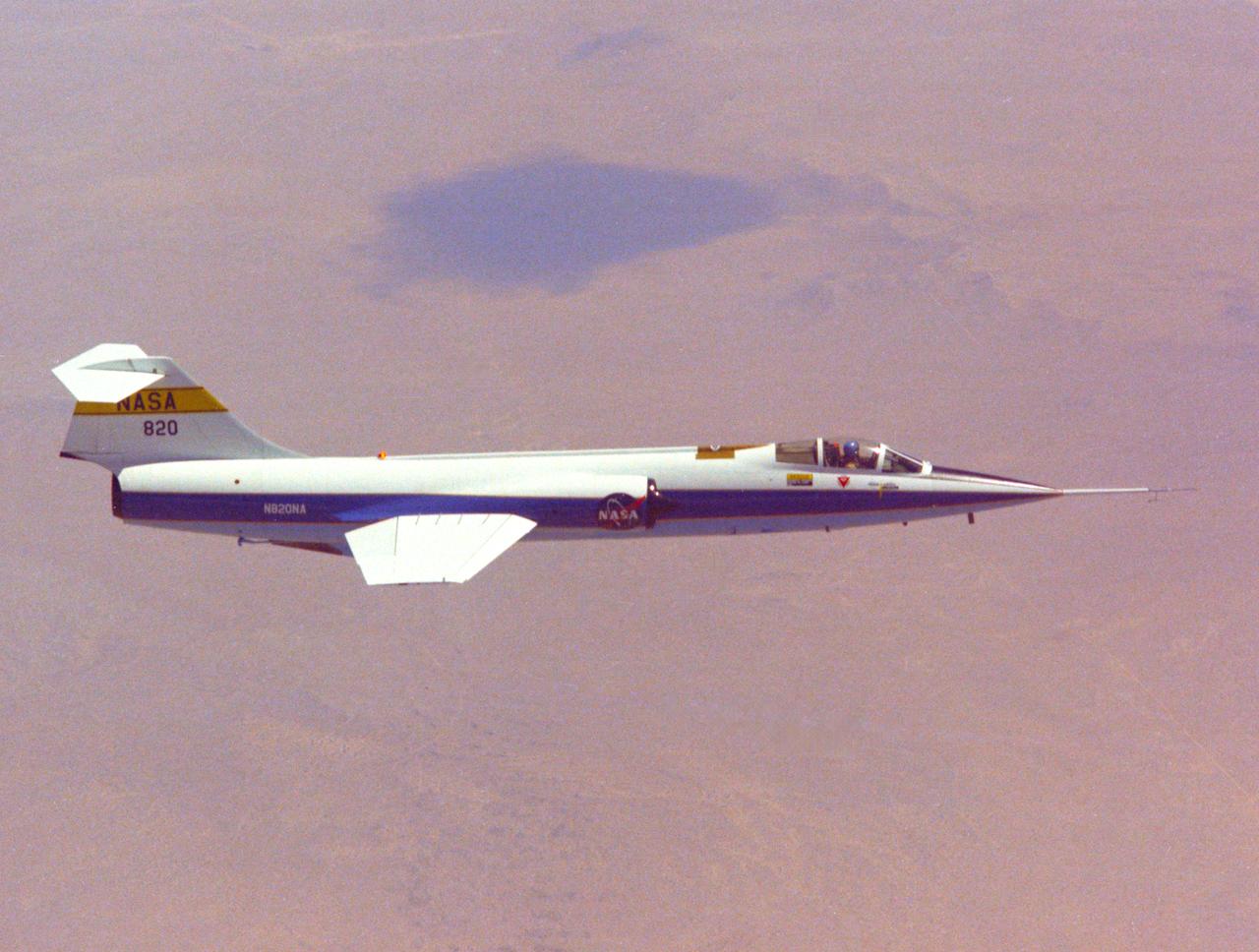
F-104A #820 in flight 8/23/71 NASA DFRC EC71-2811
Range safety and phased-array range user system antennas validated in the ECANS project can be seen just behind the cockpit on NASA's NF-15B research aircraft.
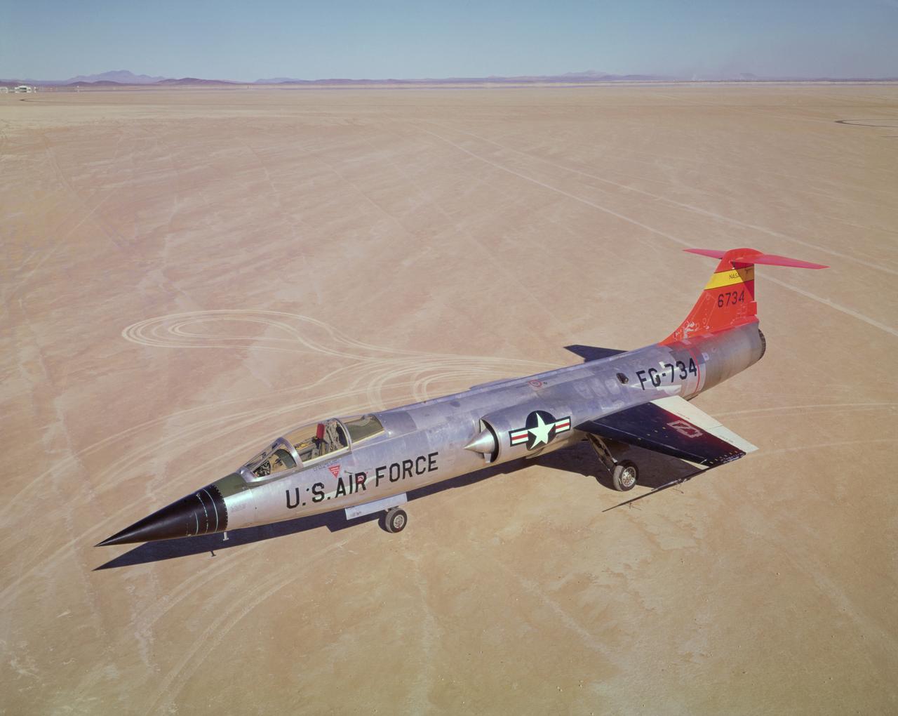
F-104A #734 on lakebed. 11/16/60
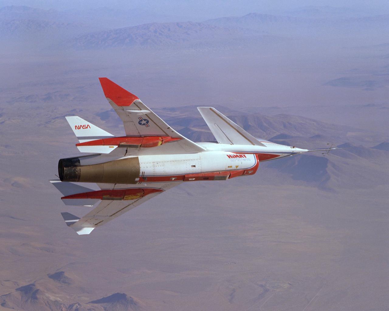
The HiMAT (Highly Maneuverable Aircraft Technology) subscale research vehicle, seen here during a research flight, was flown by the NASA Dryden Flight Research Center, Edwards, California, from mid 1979 to January 1983. The aircraft demonstrated advanced fighter technologies that have been used in the development of many modern high performance military aircraft.
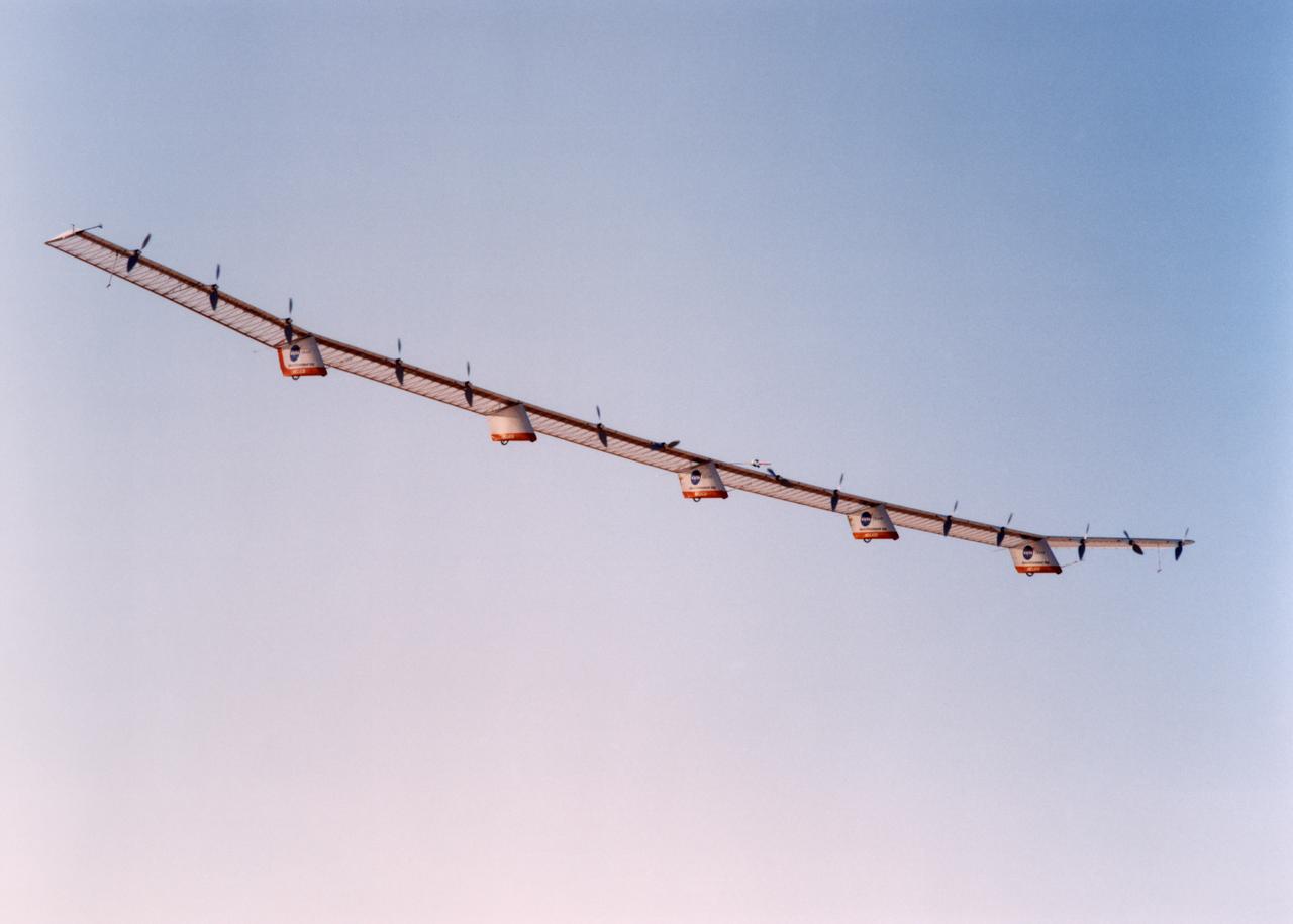
The Helios Prototype is an enlarged version of the Centurion flying wing, which flew a series of test flights at Dryden in late 1998. The craft has a wingspan of 247 feet, 41 feet greater than the Centurion, 2 1/2 times that of its solar-powered Pathfinder flying wing, and longer than either the Boeing 747 jetliner or Lockheed C-5 transport aircraft.
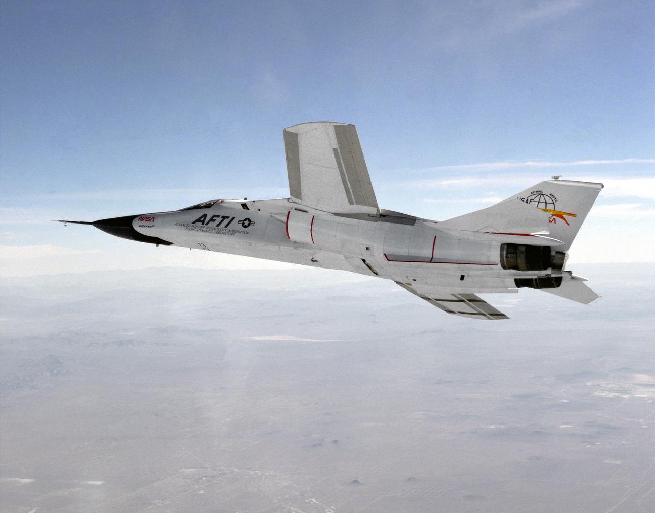
This photograph shows a modified General Dynamics AFTI/F-111A Aardvark with supercritical mission adaptive wings (MAW) installed. The AFTI/F111A is seen banking towards Rodgers Dry Lake and Edwards Air Force Base. With the phasing out of the TACT program came a renewed effort by the Air Force Flight Dynamics Laboratory to extend supercritical wing technology to a higher level of performance. In the early 1980s the supercritical wing on the F-111A aircraft was replaced with a wing built by Boeing Aircraft Company System called a “mission adaptive wing” (MAW), and a joint NASA and Air Force program called Advanced Fighter Technology Integration (AFTI) was born.
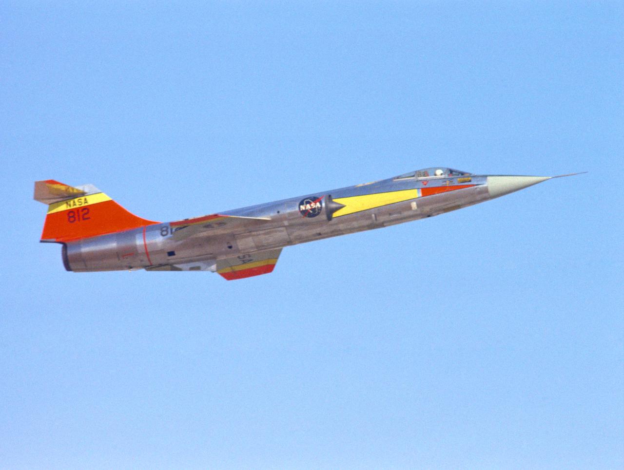
EC66-01426 F-104N #812 Take off 9/1/66
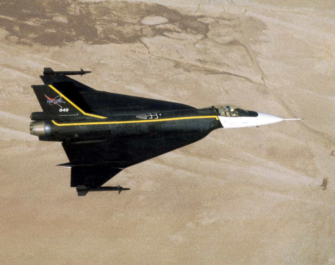
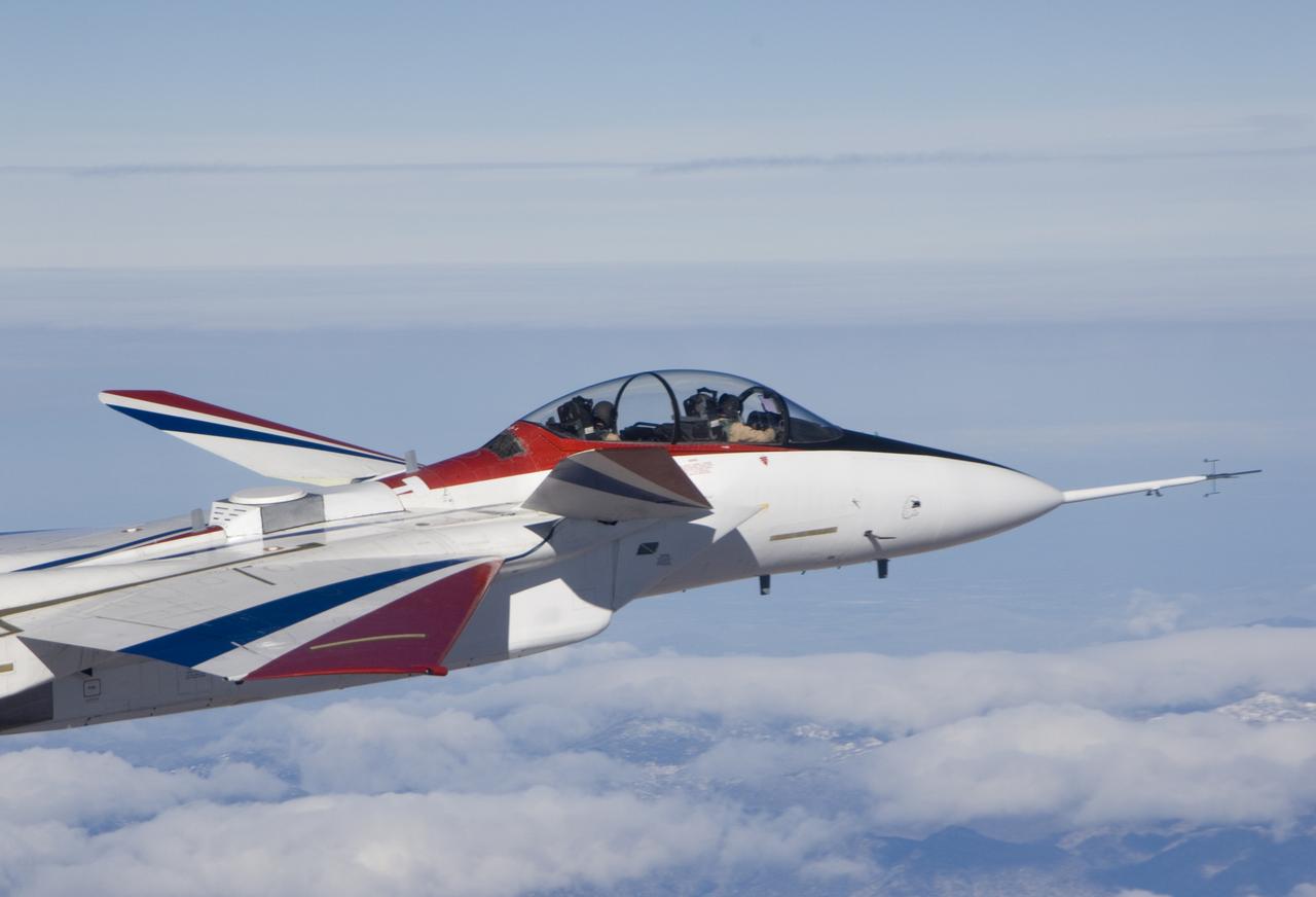
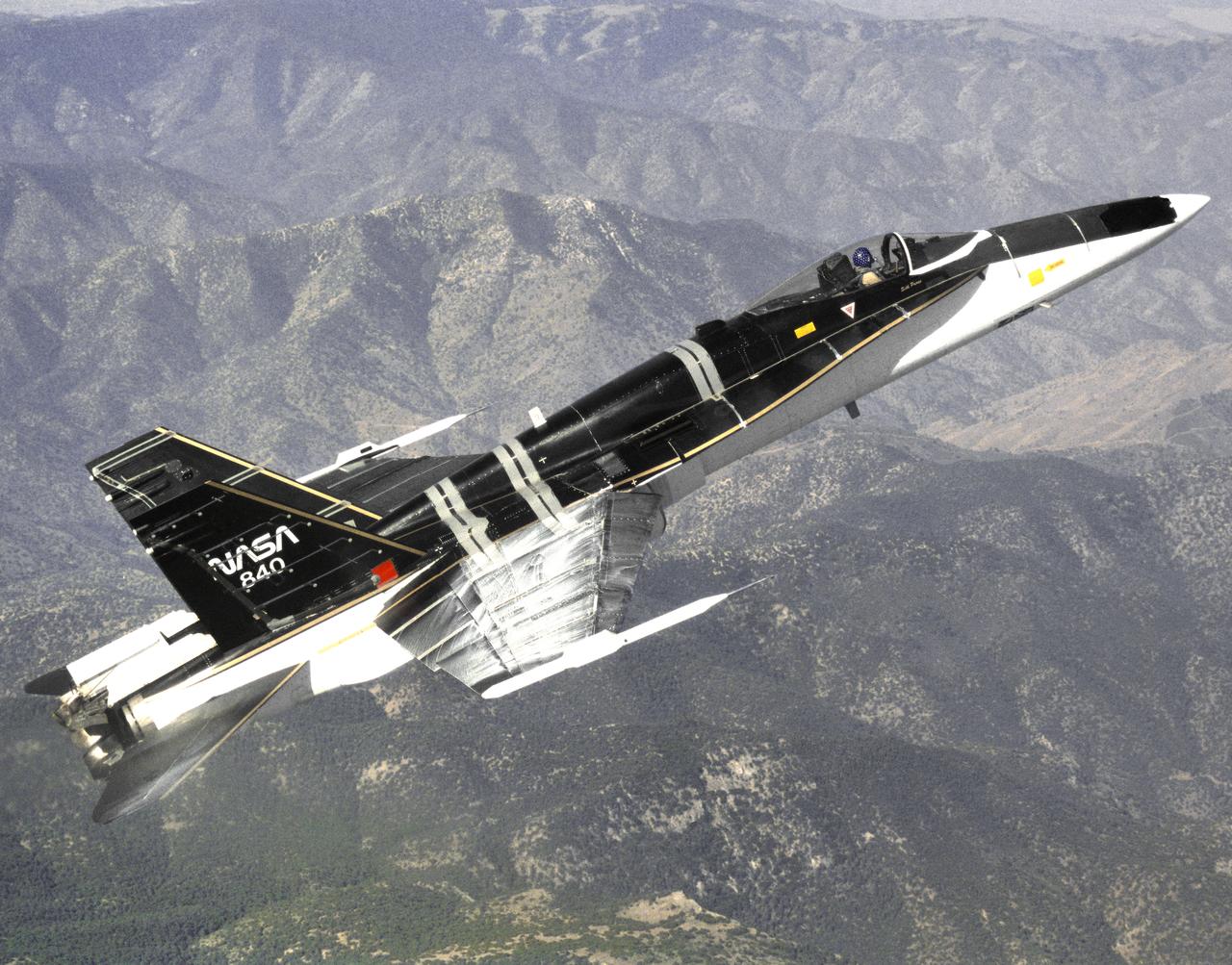
An image of the F-16XL #1 during its functional flight check of the Digital Flight Control System (DFCS) on December 16, 1997. The mission was flown by NASA research pilot Dana Purifoy, and lasted 1 hour and 25 minutes. The tests included pilot familiarly, functional check, and handling qualities evaluation maneuvers to a speed of Mach 0.6 and 300 knots. Purifoy completed all the briefed data points with no problems, and reported that the DFCS handled as well, if not better than the analog computer system that it replaced.
The Aerostructures Test Wing (ATW), which consisted of an 18-inch carbon fiber test wing with surface-mounted piezoelectric strain actuators, following intentional failure on its final flight
F-18 Systems Research Aircraft (SRA) in flight
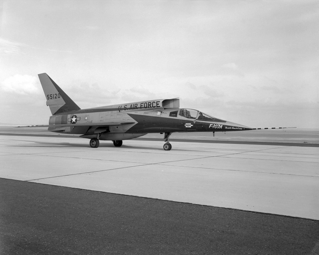
The third F-107A parked on the ramp at the Flight Research Center. Jan. 7, 1959
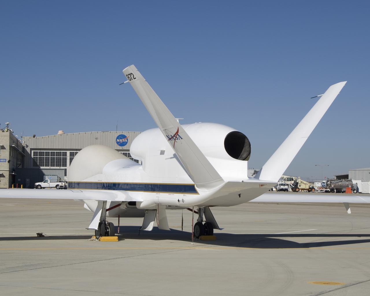
The above-the-fuselage engine and V-tail distinguish one of NASA's two Global Hawk unmanned aircraft parked on the ramp at the Dryden Flight Research Center.
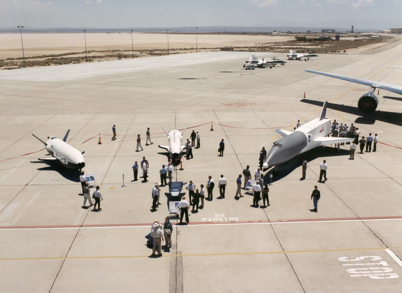
Aerospace industry representatives view actual and mock-up versions of 'X-Planes' intended to enhance access to space during a technical exposition on June 22, 2000 at Dryden Flight Research Center, Edwards, California. From left to right: NASA's B-52 launch aircraft, in service with NASA since 1959; a neutral-buoyancy model of the Boeing's X-37; the Boeing X-40A behind the MicroCraft X-43 mock-up; Orbital Science's X-34 and the modified Lockheed L-1011 airliner that was intended to launch the X-34. These X-vehicles are part of NASA's Access to Space plan intended to bring new technologies to bear in an effort to dramatically lower the cost of putting payloads in space, and near-space environments. The June 22, 2000 NASA Reusable Launch Vehicle (RLV) Technology Exposition included presentations on the history, present, and future of NASA's RLV program. Special Sessions for industry representatives highlighted the X-37 project and its related technologies. The X-37 project is managed by NASA's Marshall Space Flight Center, Huntsville, Alabama.

F-15B ACTIVE in flight
An in-flight photo of the NASA F-15A used to carry a 10 degree cone to collect aerodynamic data to calibrate the data from wind tunnels. The flight was made on May 17, 1978. Acting as chase for the flight was a NASA F-104 aircraft.

NASA Dryden F-18 #843 in flight
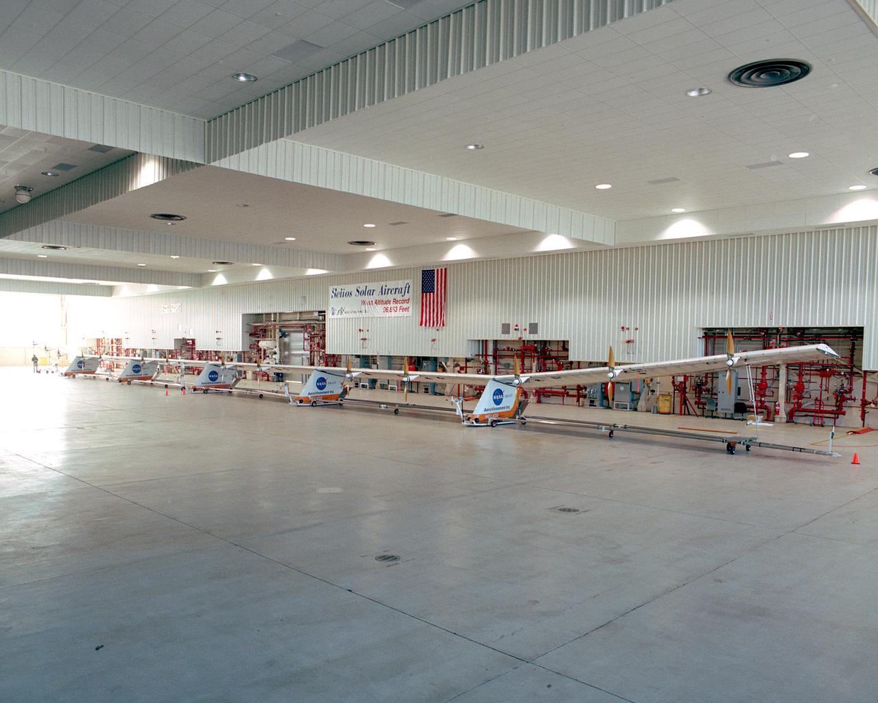
The Helios Prototype flying wing stretches almost the full length of the 300-foot-long hangar at NASA's Dryden Flight Research Center, Edwards, California. The 247-foot span solar-powered aircraft, resting on its ground maneuvering dolly, was on display for a visit of NASA Administrator Sean O'Keefe and other NASA officials on January 31, 2002. The unique solar-electric flying wing reached an altitude of 96,863 feet during an almost 17-hour flight near Hawaii on August 13, 2001, a world record for sustained horizontal flight by a non-rocket powered aircraft. Developed by AeroVironment, Inc., under NASA's Environmental Research Aircraft and Sensor Technology (ERAST) project, the Helios Prototype is the forerunner of a planned fleet of slow-flying, long duration, high-altitude uninhabited aerial vehicles (UAV) which can serve as "atmospheric satellites," performing Earth science missions or functioning as telecommunications relay platforms in the stratosphere.
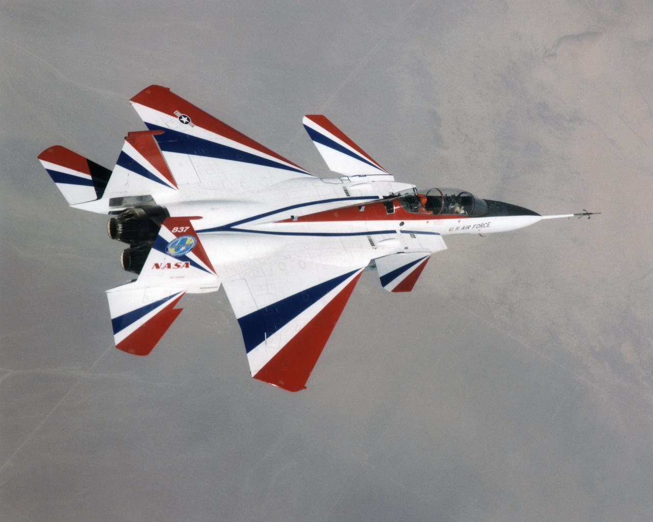
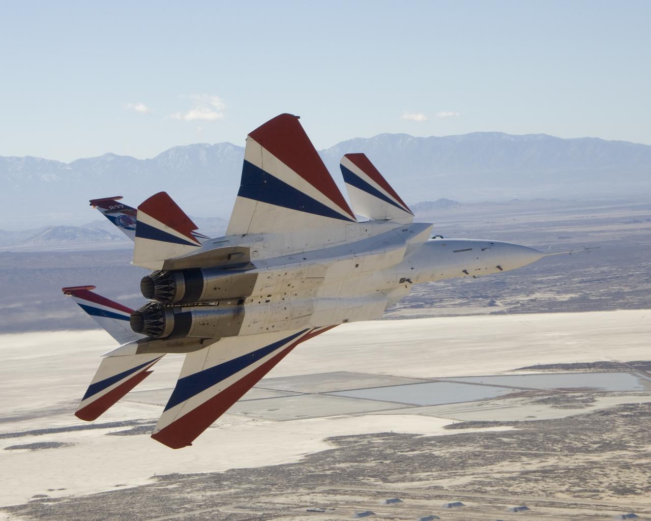
The F-15 ACTIVE in flight above the Mojave desert on April 14, 1998. The overhead shot shows the aircraft's striking red and while paint scheme/ The large forward canards are actually the tail surfaces from an F-18.
Dryden Aircraft Fleet on ramp and facility - 1988
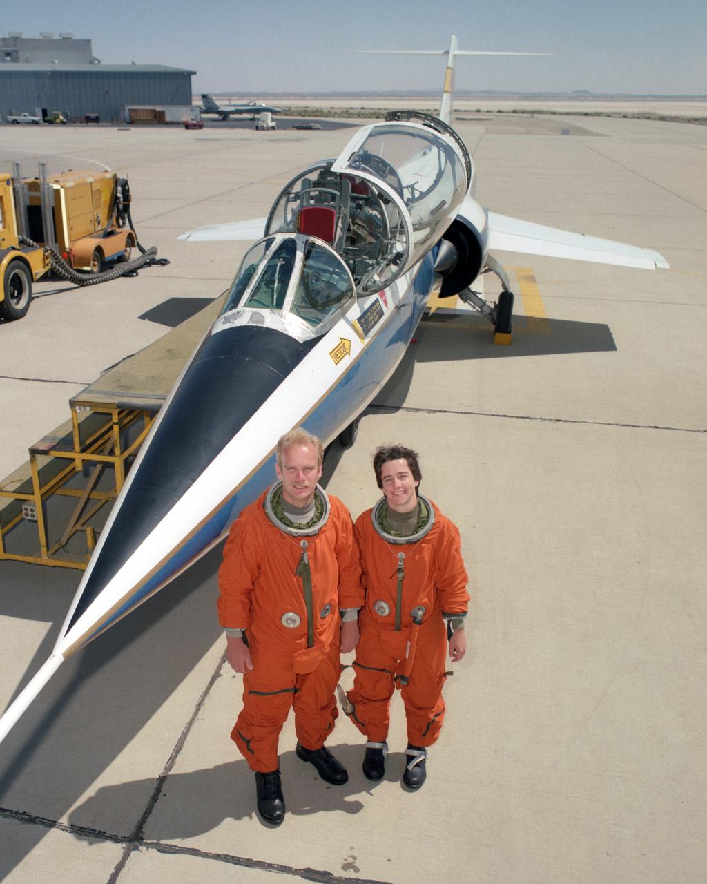
Flight test engineers Bob Meyer and Marta Bohn-Meyer had the distinction of being the only married couple to both serve on flight status on this two-seat F-104 at NASA Dryden.
The single-seat F-16XL, NASA 849, joins up with an SR-71A, NASA 844, as crews set up for one of the flights in the recent sonic boom research program conducted by the Dryden Flight Research Center, Edwards, California. During the missions, the F-16XL probed the shockwaves generated by the SR-71, while at lower altitudes sensors on an F-18 and on a YO-3A, and also on the ground, recorded data from the same shockwave.

ER-2 tail number 809, is one of two Airborne Science ER-2s used as science platforms by Dryden. The aircraft are platforms for a variety of high-altitude science missions flown over various parts of the world. They are also used for earth science and atmospheric sensor research and development, satellite calibration and data validation. The ER-2s are capable of carrying a maximum payload of 2,600 pounds of experiments in a nose bay, the main equipment bay behind the cockpit, two wing-mounted superpods and small underbody and trailing edges. Most ER-2 missions last about six hours with ranges of about 2,200 nautical miles. The aircraft typically fly at altitudes above 65,000 feet. On November 19, 1998, the ER-2 set a world record for medium weight aircraft reaching an altitude of 68,700 feet. The aircraft is 63 feet long, with a wingspan of 104 feet. The top of the vertical tail is 16 feet above ground when the aircraft is on the bicycle-type landing gear. Cruising speeds are 410 knots, or 467 miles per hour, at altitude. A single General Electric F118 turbofan engine rated at 17,000 pounds thrust powers the ER-2.
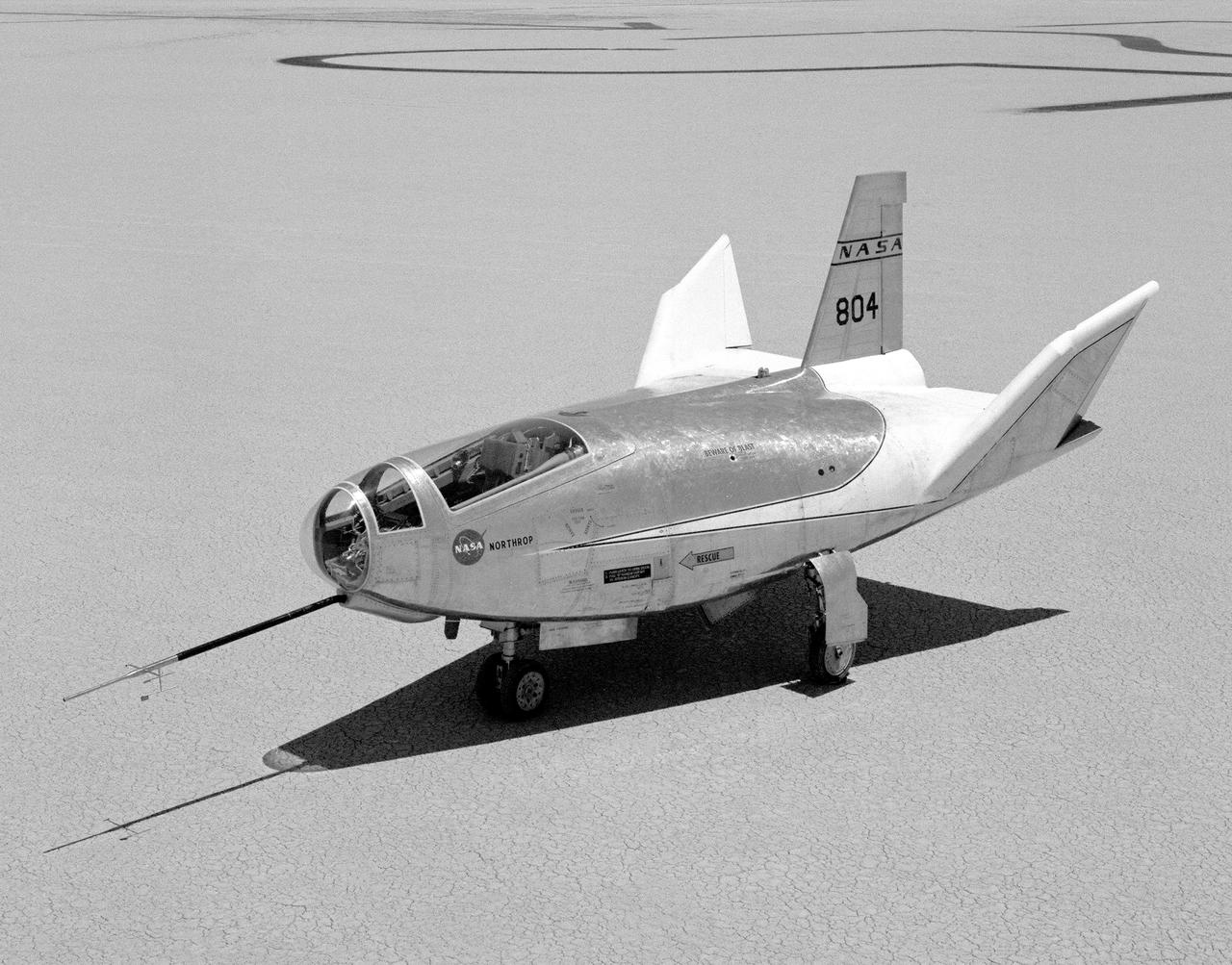
The HL-10 Lifting Body is seen here parked on Rogers Dry Lake, the unique location where it landed after research flights. This 1968 photo shows the vehicle after the fins were modified to remove instabilities encountered on the first flight. It involved a change to the shape of the leading edge of the fins to eliminate flow separation. It required extensive wind-tunnel testing at Langley Research Center, Hampton, Va. NASA Flight Research Center (FRC) engineer Bob Kempel than plotted thousands of data points by hand to come up with the modification, which involved a fiberglass glove backed with a metal structure on each fin's leading edge. This transformed the vehicle from a craft that was difficult to control into the best handling of the original group of lifting bodies at the FRC.
The modified F-18 High Alpha Research Vehicle (HARV) carries out air flow studies on a flight from the Dryden Flight Research Center, Edwards, California. Using oil, researchers were able to track the air flow across the wing at different speeds and angles of attack. A thrust vectoring system had been installed on the engines' exhaust nozzles for the high angle of attack research program. The thrust vectoring system, linked to the aircraft's flight control system, moves a set of three paddles on each engine to redirect thrust for directional control and increased maneuverability at angles of attack at up to 70 degrees.
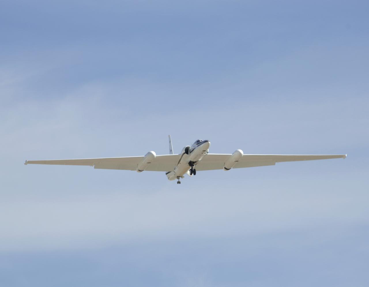
One of NASA's two ER-2 Earth resources aircraft shows off its lines during a flyover at the Edwards Air Force Base open house Oct. 28-29, 2006.
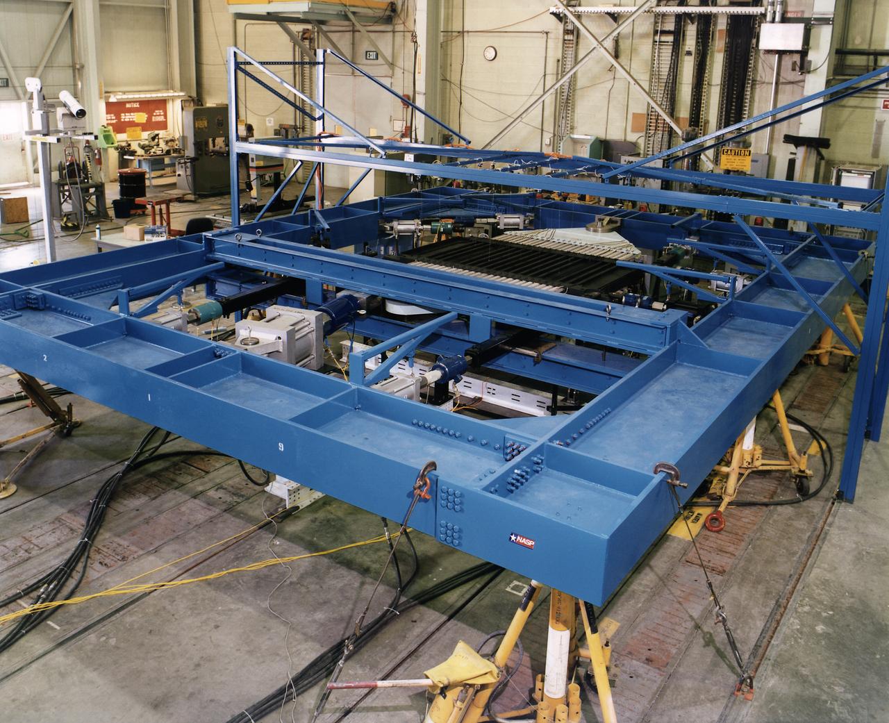
Combined Loads Test Fixture with NASP test article installed
Two small Range Safety System antennas are located just behind the engine inlets of NASA's NF-15B research aircraft as it banks away from the chase plane.
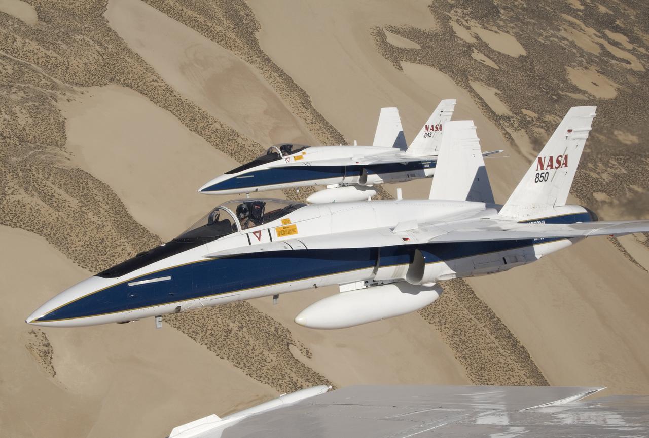
Two NASA Dryden F/A-18s flown by research pilots Frank Batteas and Nils Larson were captured by photographer Lori Losey from a third F/A-18 flown by Dick Ewers as they flew in tight formation over the desert at Edwards Air Force Base.
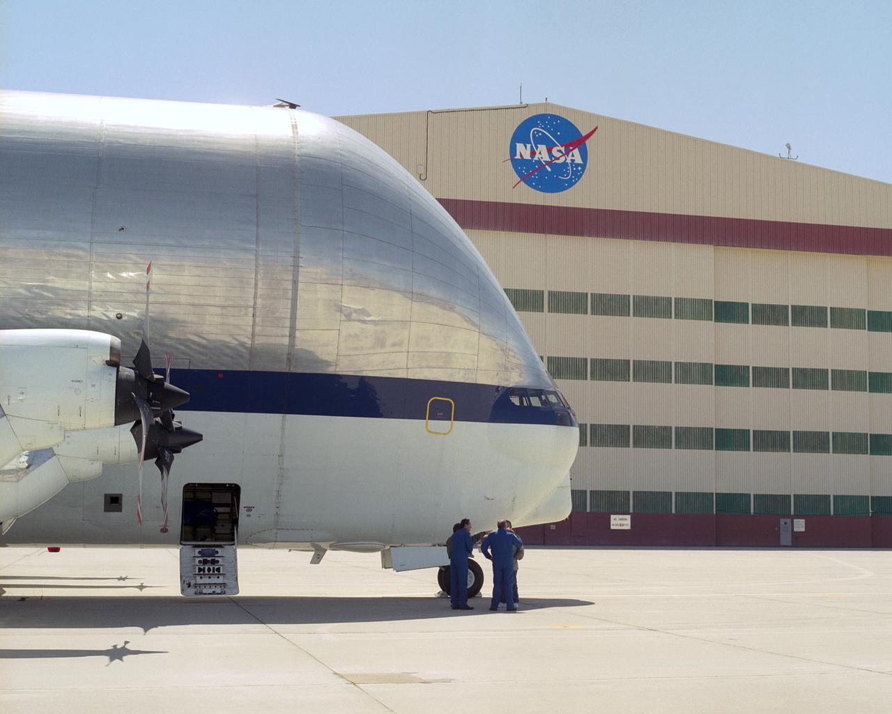
NASA's outsize Super Guppy cargo plane dwarfs its flight crew after its arrival at NASA Dryden Flight Research Center for a landing gear change.
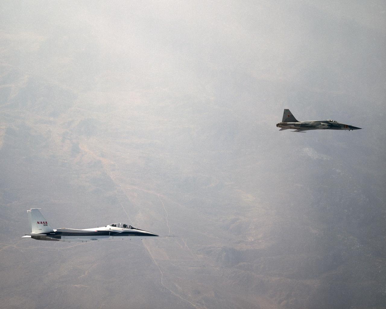
NASA's F-15B Research Testbed aircraft recently flew in the supersonic shock wave of a U.S. Navy F-5E in support of the F-5 Shaped Sonic Boom Demonstration (SSBD) project, part of the Defense Advanced Research Projects Agency's (DARPA) Quiet Supersonic Platform (QSP) program. The flights originated from the NASA Dryden Flight Research Center at Edwards, California. Four flights were flown in order to measure the F-5E's near-field (close-up) sonic boom signature at Mach 1.4, during which more than 50 shockwave patterns were measured at distances as close as 100 feet below the F-5E.
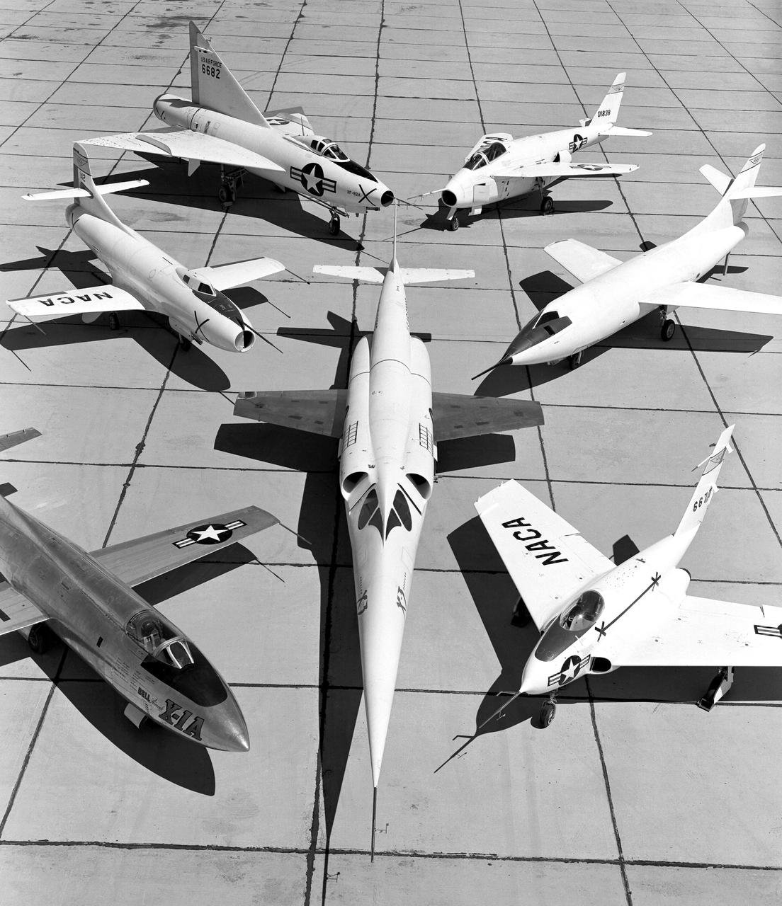
X-3 (center), and clockwise from left: X-1A, D-558-I, XF-92A, X-5, D-558-II, and X-4.
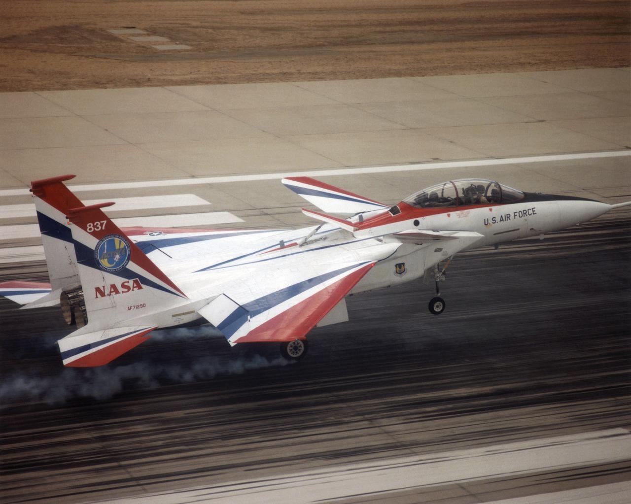
The F-15 ACTIVE touches down on the Edwards runway following its April 14, 1998 flight. The nose is high while the canards have their rear edge raised. the aircraft's speed brake, located on the top of the aircraft behind the canopy, is also raised.
The Aerostructures Test Wing (ATW), which consisted of an 18-inch carbon fiber test wing with surface-mounted piezoelectric strain actuators, was mounted on a special ventral flight test fixture and flown on Dryden's F-15B Research Testbed aircraft
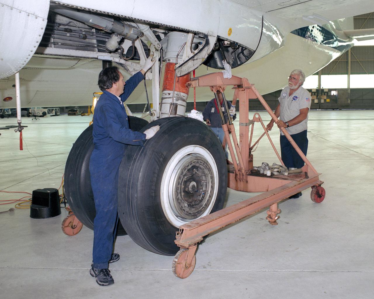
JSC technicians David Wyckoff and Tom Gordon carefully maneuver their equipment into place as they prepare to remove the Super Guppy's left main landing gear.
The three thrust-vectoring aircraft at Edwards, California, each capable of flying at extreme angles of attack, cruise over the California desert in formation during flight in March 1994. They are, from left, NASA's F-18 High Alpha Research Vehicle (HARV), flown by the NASA Dryden Flight Research Center; the X-31, flown by the X-31 International Test Organization (ITO) at Dryden; and the Air Force F-16 Multi-Axis Thrust Vectoring (MATV) aircraft.
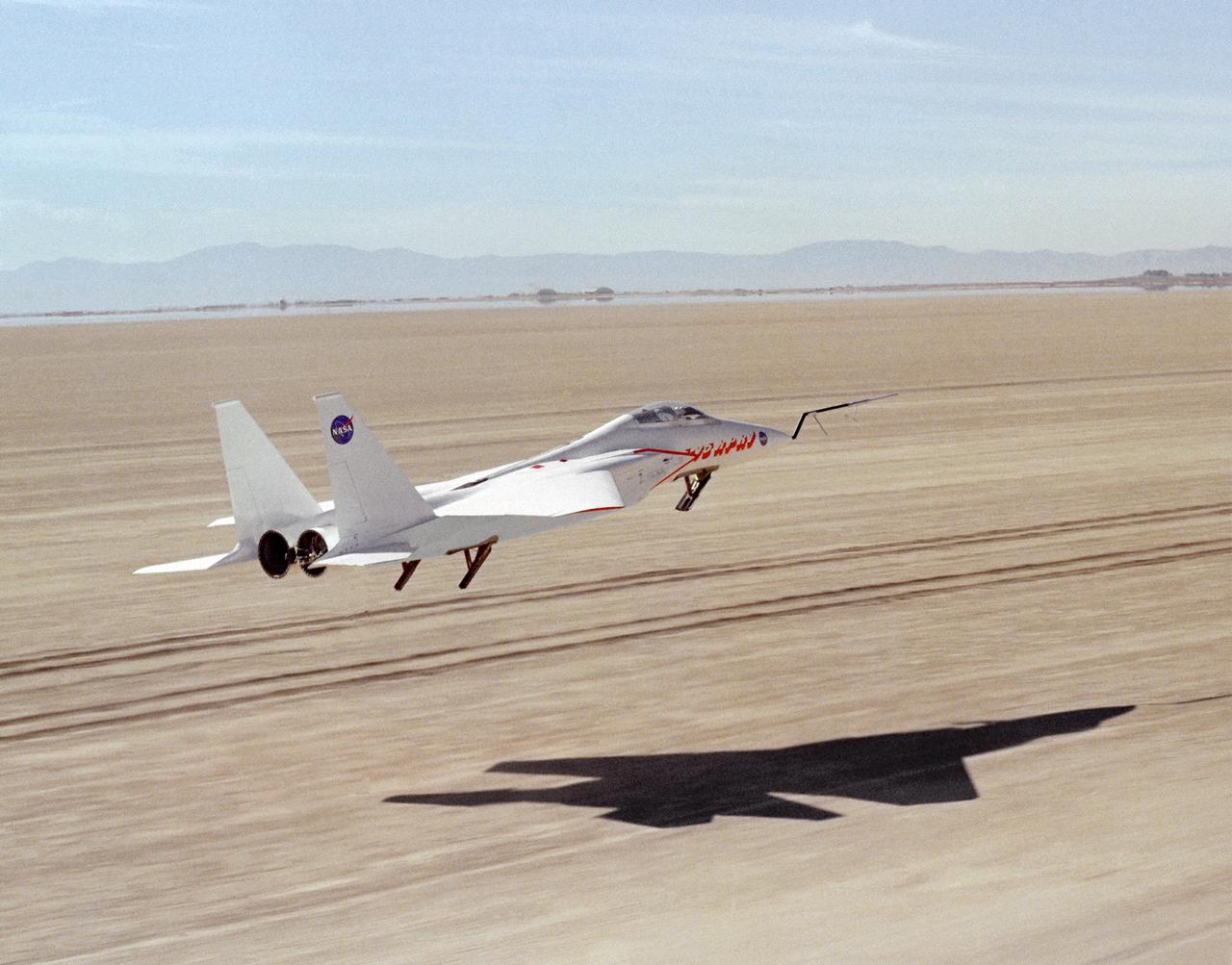
This photograph shows NASA's 3/8th-scale remotely piloted research vehicle landing on Rogers Dry Lakebed at Edwards Air Force Base, California, in 1975.
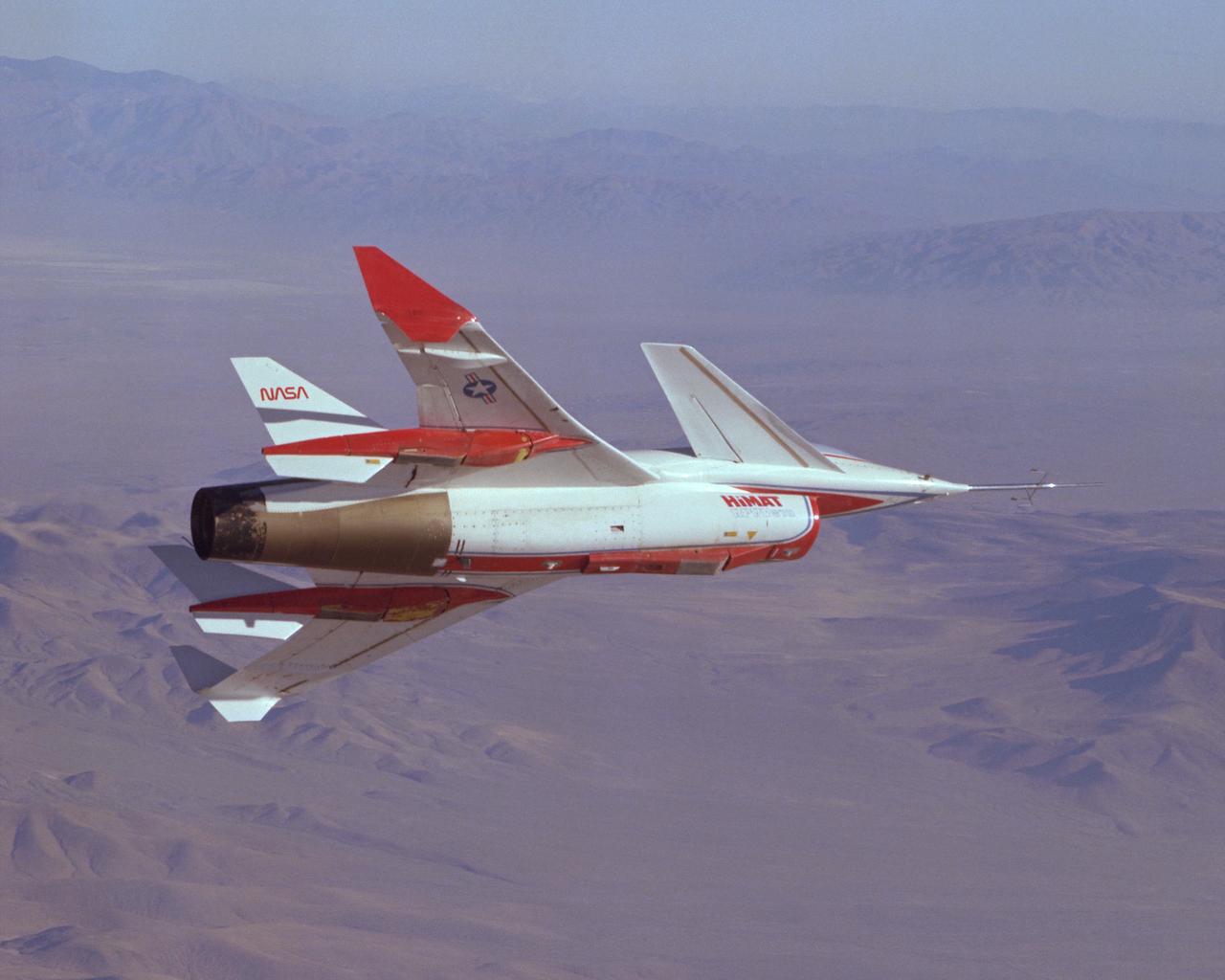
The HiMAT (Highly Maneuverable Aircraft Technology) subscale research vehicle, seen here during a research flight, was flown by the NASA Dryden Flight Research Center, Edwards, California, from mid 1979 to January 1983. The aircraft demonstrated advanced fighter technologies that have been used in the development of many modern high performance military aircraft.
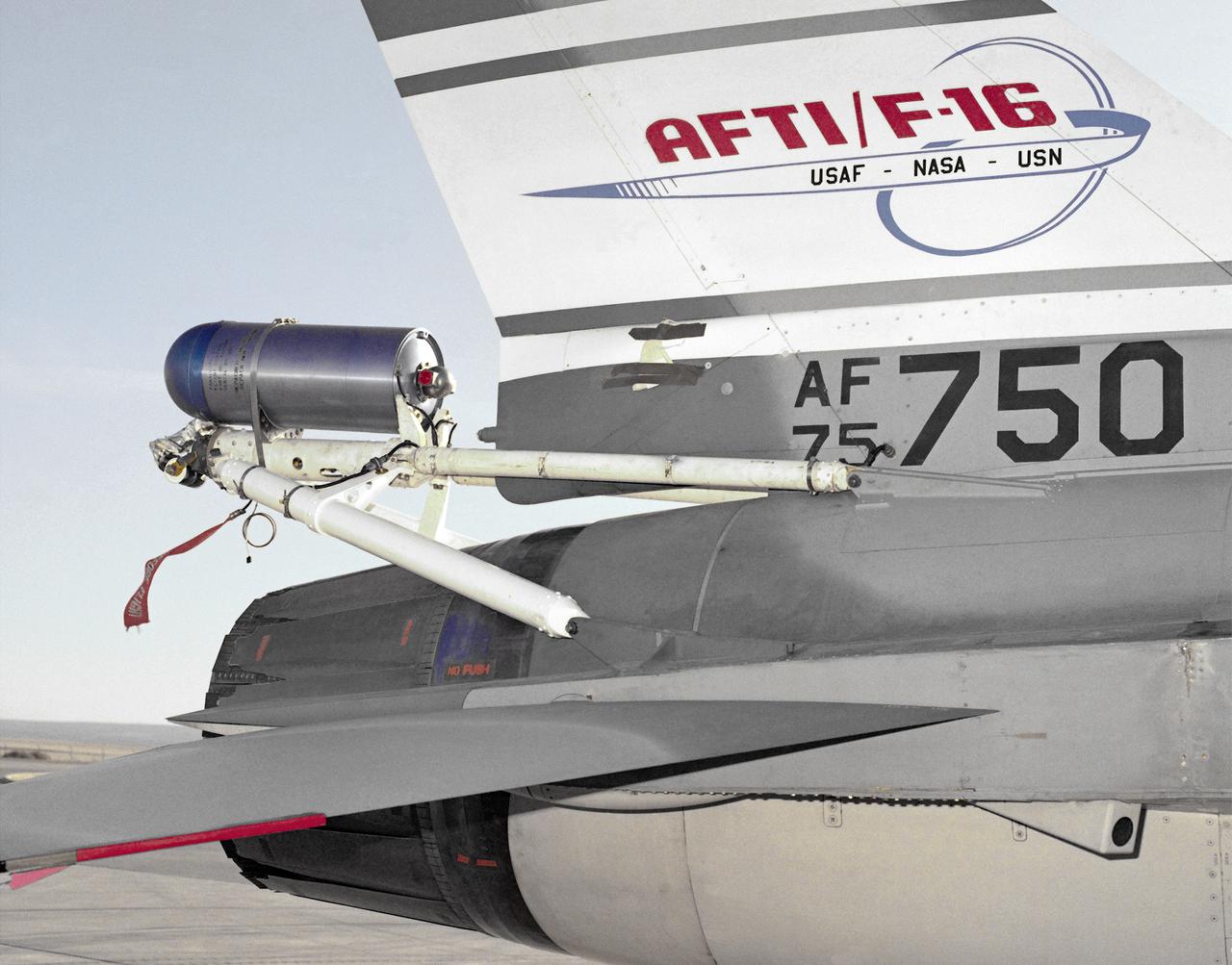
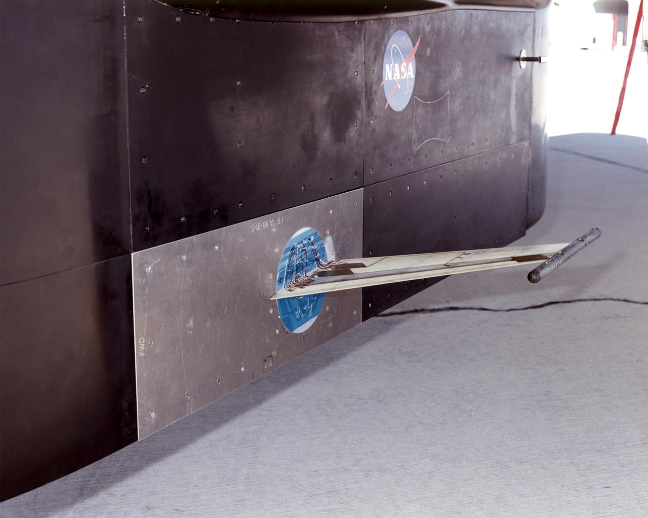
A close-up photo of the spin chute mounted on the rear fuselage of the AFTI F-16, a safety device designed to prevent the loss of aircraft in spin conditions. Under some circumstances, pilots cannot recover from spins using normal controls. It these instances, the spin chute is deployed, thus "breaking" the spin and enabling the pilot to recover. The spin chute is held in a metal cylinder attached to the AFTI F-16 by four tubes, a structure strong enough to withstand the shock of the spin chute opening. Unlike the air probe in the last photo, spin chutes are not standard equipment on research or prototype aircraft but are commonly attached expressly for actual spin tests.

F-15B ACTIVE in flight
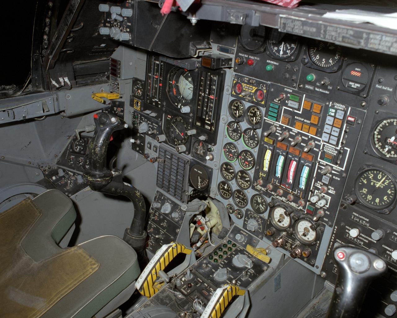
View of the left cockpit and pilot's seat of the F-111 MAW aircraft. Unlike most fighter aircraft of the time, the F-111 had side-by-side seating. The pilot sat on the left side, and the weapons systems officer on the right. Both had control sticks to fly the aircraft. The two yellow and black striped handles would be used in an emergency to eject the entire F-111 cockpit. The F-111 also did not have ejection seats, but used a capsule.
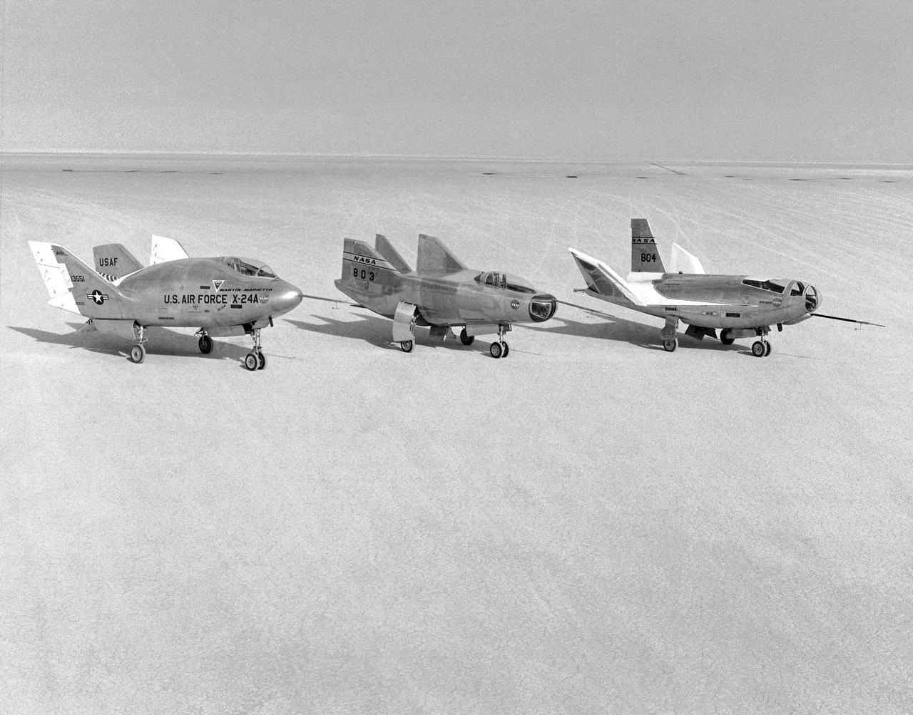
The wingless, lifting body aircraft sitting on Rogers Dry Lake at what is now NASA's Dryden Flight Research Center, Edwards, California, from left to right are the X-24A, M2-F3 and the HL-10. The lifting body aircraft studied the feasibility of maneuvering and landing an aerodynamic craft designed for reentry from space. These lifting bodies were air launched by a B-52 mother ship, then flew powered by their own rocket engines before making an unpowered approach and landing. They helped validate the concept that a space shuttle could make accurate landings without power. The X-24A flew from April 17, 1969 to June 4, 1971. The M2-F3 flew from June 2, 1970 until December 20, 1972. The HL-10 flew from December 22, 1966 until July 17, 1970 and logged the highest and fastest records in the lifting body program.
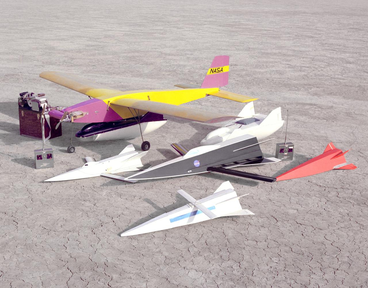
Flight Research Center and Dryden Flight Research Center engineer R. Dale Reed has long used free-flight models to test new concepts. This photo from 1963 shows two different models of the M2-F2 (one under the Mothership) and four Hyper III shapes.
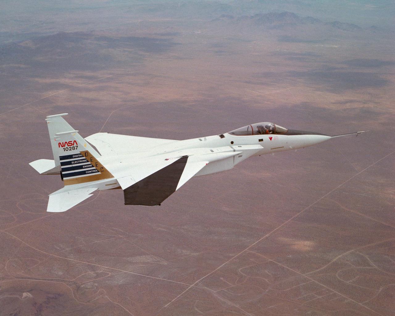
Digital Electronic Engine Control F-15A #287 in flight over California City. Note wing deflection measurement system on right wing.

ER-2 tail number 806, is one of two Airborne Science ER-2s used as science platforms by Dryden. The aircraft are platforms for a variety of high-altitude science missions flown over various parts of the world. They are also used for earth science and atmospheric sensor research and development, satellite calibration and data validation. The ER-2s are capable of carrying a maximum payload of 2,600 pounds of experiments in a nose bay, the main equipment bay behind the cockpit, two wing-mounted superpods and small underbody and trailing edges. Most ER-2 missions last about six hours with ranges of about 2,200 nautical miles. The aircraft typically fly at altitudes above 65,000 feet. On November 19, 1998, the ER-2 set a world record for medium weight aircraft reaching an altitude of 68,700 feet. The aircraft is 63 feet long, with a wingspan of 104 feet. The top of the vertical tail is 16 feet above ground when the aircraft is on the bicycle-type landing gear. Cruising speeds are 410 knots, or 467 miles per hour, at altitude. A single General Electric F-118 turbofan engine rated at 17,000 pounds thrust powers the ER-2.

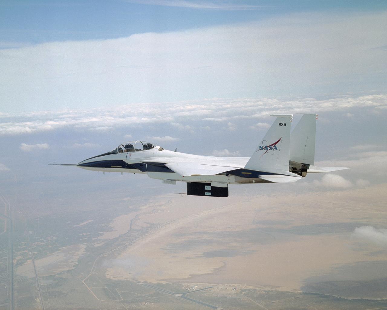
In-flight photo of the NASA F-15B used in tests of the X-33 Thermal Protection System (TPS) materials. Flying at subsonic speeds, the F-15B tests measured the air loads on the proposed X-33 protective materials. In contrast, shock loads testing investigated the local impact of the supersonic shock wave itself on the TPS materials. Similar tests had been done in 1985 for the space shuttle tiles, using an F-104 aircraft.
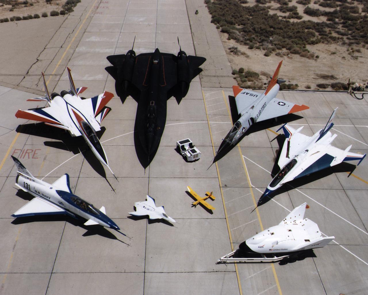
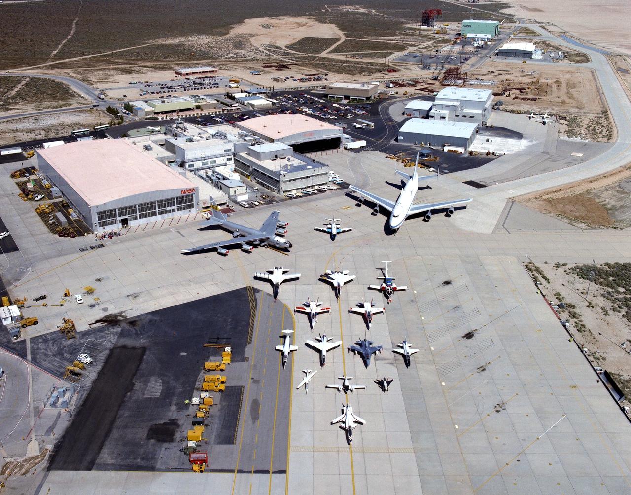
A collection of NASA's research aircraft on the ramp at the Dryden Flight Research Center in July 1997: X-31, F-15 ACTIVE, SR-71, F-106, F-16XL Ship #2, X-38, Radio Controlled Mothership and X-36.
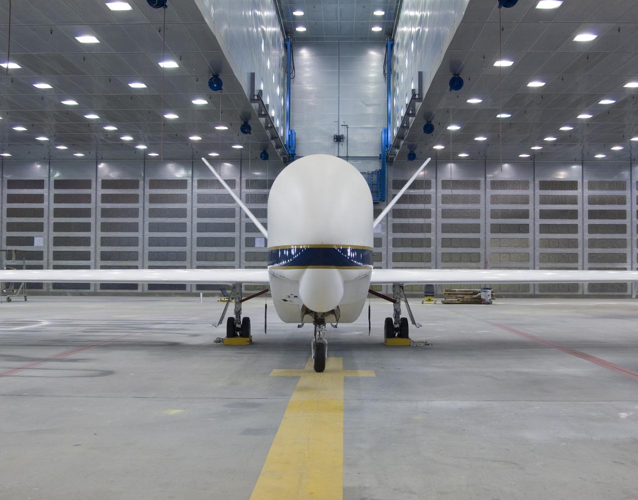
The bulbous nose of one of NASA's Global Hawk unmanned aircraft sports a blue-and-white paint scheme after repainting in the Edwards Air Force Base paint shop.
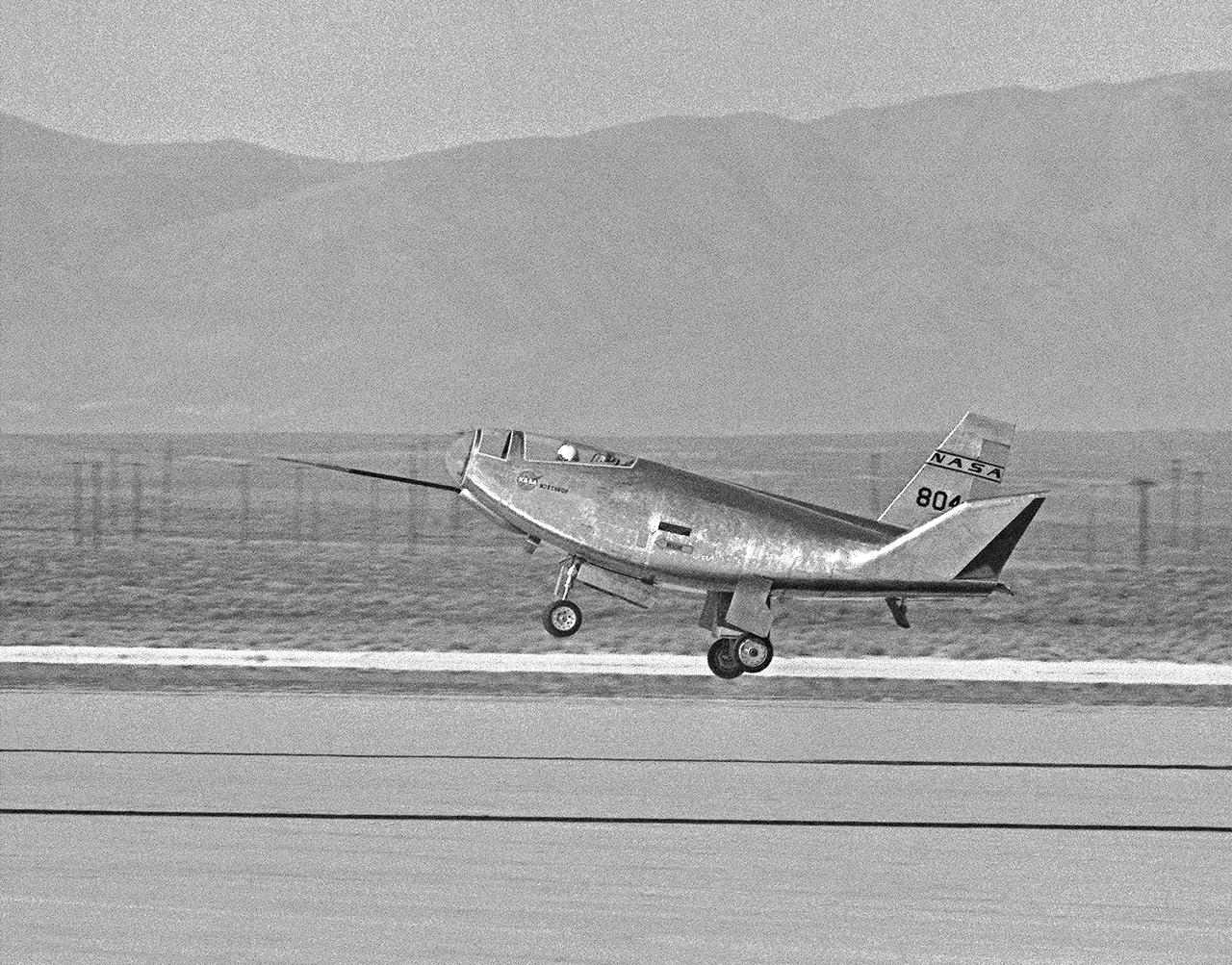
The HL-10 Lifting Body completes its first research flight with a landing on Rogers Dry Lake. Due to control problems, pilot Bruce Peterson had to land at a higher speed than originally planned in order to keep the vehicle under control. The actual touchdown speed was about 280 knots. This was 30 knots above the speed called for in the flight plan. The HL-10's first flight had lasted 3 minutes and 9 seconds.
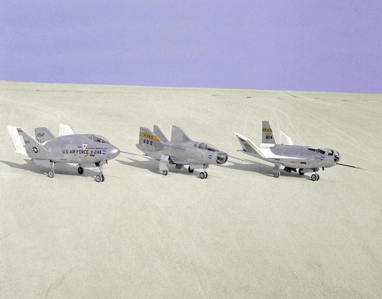
The wingless, lifting body aircraft sitting on Rogers Dry Lake at what is now NASA's Dryden Flight Research Center, Edwards, California, from left to right are the X-24A, M2-F3 and the HL-10. The lifting body aircraft studied the feasibility of maneuvering and landing an aerodynamic craft designed for reentry from space. These lifting bodies were air launched by a B-52 mother ship, then flew powered by their own rocket engines before making an unpowered approach and landing. They helped validate the concept that a space shuttle could make accurate landings without power. The X-24A flew from April 17, 1969 to June 4, 1971. The M2-F3 flew from June 2, 1970 until December 21, 1971. The HL-10 flew from December 22, 1966 until July 17, 1970, and logged the highest and fastest records in the lifting body program.
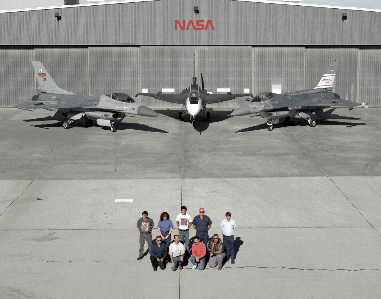
The support crew for the F-16A, the F-16XL no. 1, and the F-16 AFTI are, top row, left to right: Randy Weaver; mechanic, Susan Ligon; mechanic, Bob Garcia; Crew Chief, Rich Kelly; mechanic, Dale Edminister; Avionics Technician. Bottom row, left to right, Art Cope; mechanic, John Huffman; Avionics Technician, Jaime Garcia; Avionics Technician, Don Griffith, Avionics Tech. Co-op student. The F-16A (NASA 516), the only civil registered F-16 in existence, was transferred to Dryden from Langley, and was primarily used in engine tests and for parts. It was subsequently transfered from Dryden. The single-seat F-16XL no. 1 (NASA 849) was most recently used in the Cranked-Arrow Wing Aerodynamics Project (CAWAP) to test boundary layer pressures and distribution. Previously it had been used in a program to investigate the characteristics of sonic booms for NASA's High Speed Research Program. Data from the program will be used in the development of a high speed civilian transport. During the series of sonic boom research flights, the F-16XL was used to probe the shock waves being generated by a NASA SR-71 and record their shape and intensity. The Advanced Fighter Technology Integration (AFTI) F-16 was used to develop and demonstrate technologies to improve navigation and a pilot's ability to find and destroy enemy ground targets day or night, including adverse weather. Earlier research in the joint NASA-Air Force AFTI F-16 program demonstrated voice actuated controls, helmet-mounted sighting and integration of forward-mounted canards with the standard flight control system to achieve uncoupled flight.
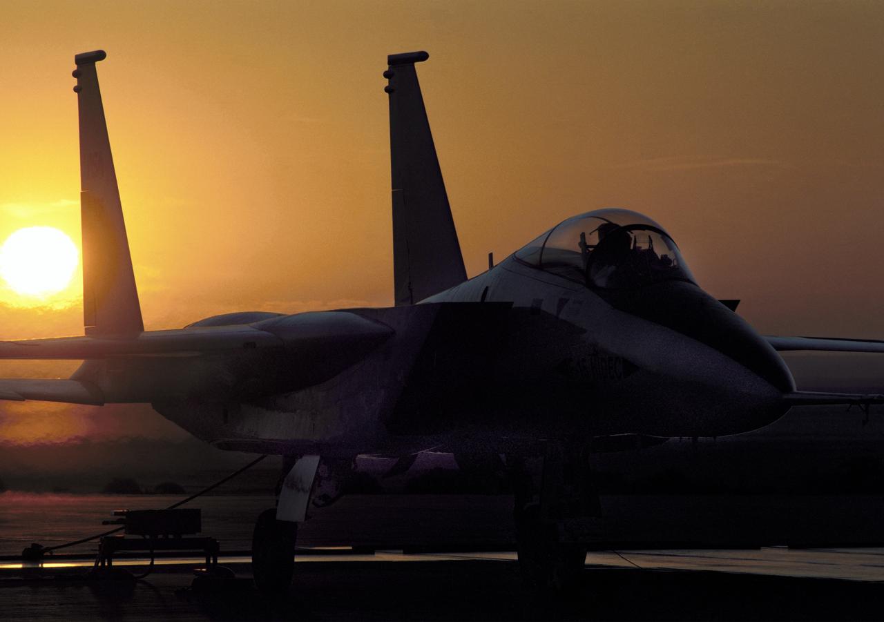
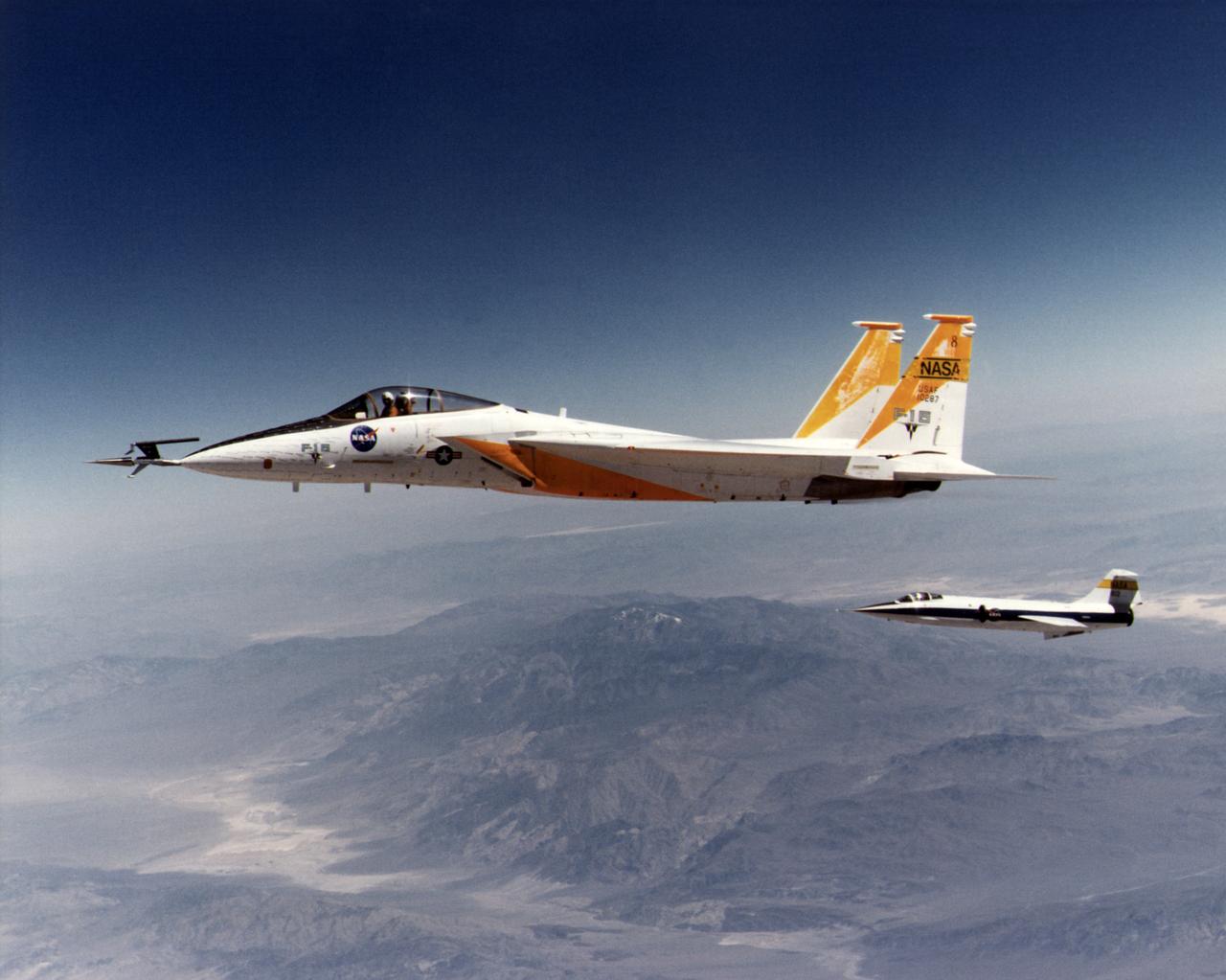
NASA's highly modified F-15A (Serial #71-0287) used for digital electronic flight and engine control systems research, at sunrise on the ramp at the Dryden Flight Research Facility, Edwards, California. The F-15 was called the HIDEC (Highly Integrated Digital Electronic Control) flight facility. Research programs flown on the testbed vehicle have demonstrated improved rates of climb, fuel savings, and engine thrust by optimizing systems performance. The aircraft also tested and evaluated a computerized self-repairing flight control system for the Air Force that detects damaged or failed flight control surfaces. The system then reconfigures undamaged control surfaces so the mission can continue or the aircraft is landed safely.
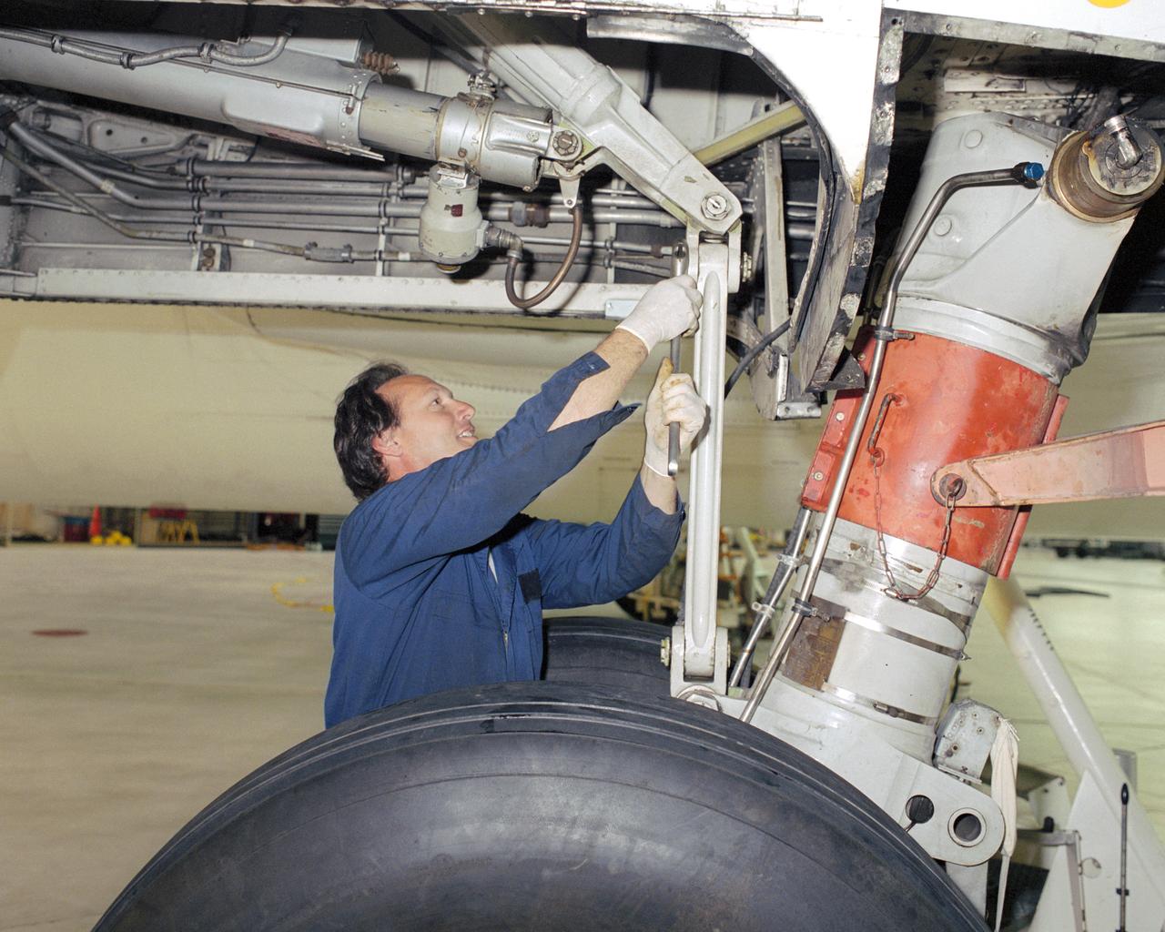
Assistant crew chief David Wyckoff applies some elbow grease to loosen a link pin during a landing gear changeout on NASA Johnson Space Center's Super Guppy.
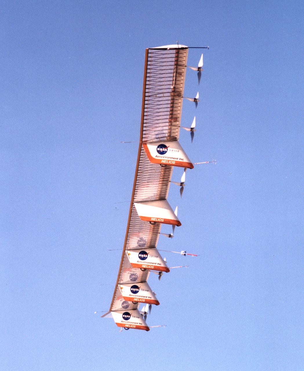
The Helios Prototype is an enlarged version of the Centurion flying wing, which flew a series of test flights at Dryden in late 1998. The craft has a wingspan of 247 feet, 41 feet greater than the Centurion, 2 1/2 times that of its solar-powered Pathfinder flying wing, and longer than either the Boeing 747 jetliner or Lockheed C-5 transport aircraft.
The HL-10 Lifting Body is seen here in powered flight shortly after launch from the B-52 mothership. When HL-10 powered flights began on October 23, 1968, the vehicle used the same basic XLR-11 rocket engine that powered the original X-1s. A total of five powered flights were made before the HL-10 first flew supersonically on May 9, 1969, with John Manke in the pilot's seat.
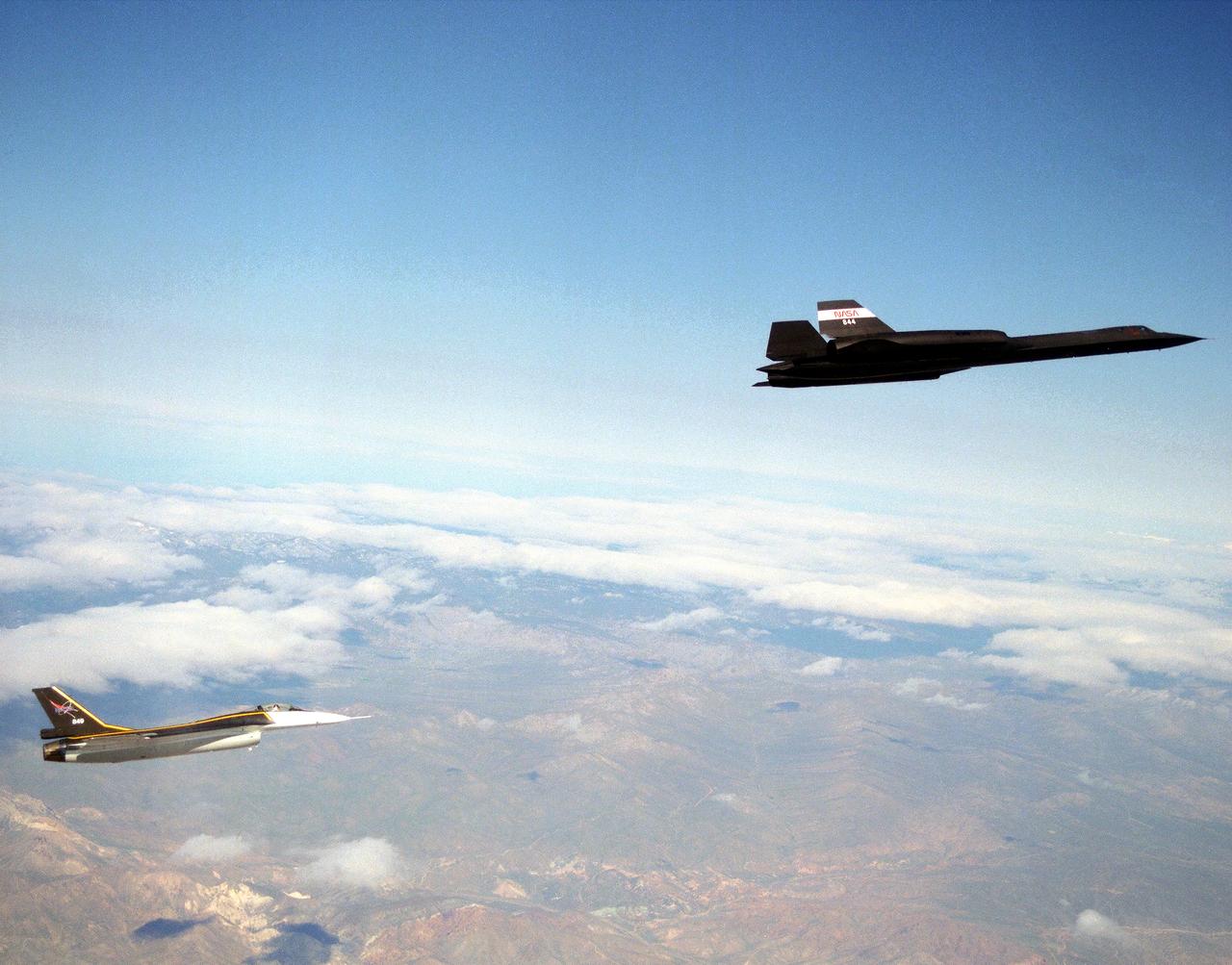
The single-seat F-16XL, NASA 849, joins up with an SR-71A, NASA 844, as crews set up for one of the flights in the recent sonic boom research program conducted by the Dryden Flight Research Center, Edwards, California. During the missions, the F-16XL probed the shockwaves generated by the SR-71, while at lower altitudes sensors on an F-18 and on a YO-3A, and also on the ground, recorded data from the same shockwave.
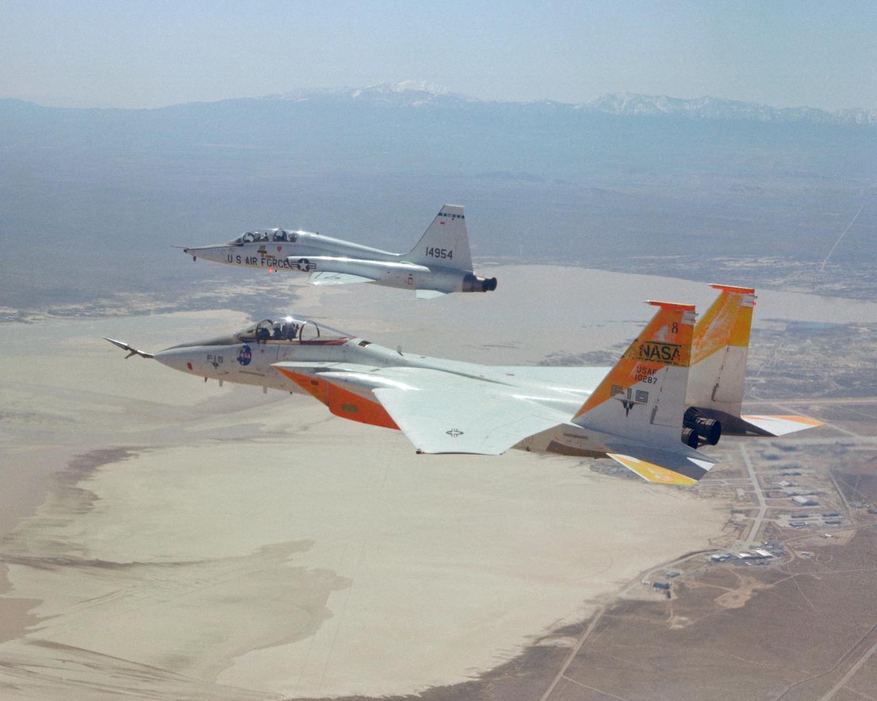
An in-flight photo of the NASA F-15A used to carry a 10 degree cone to collect aerodynamic data to calibrate the data from wind tunnels. Acting as chase for the flight was a NASA T-38 aircraft.

F-15A #281 In Flight
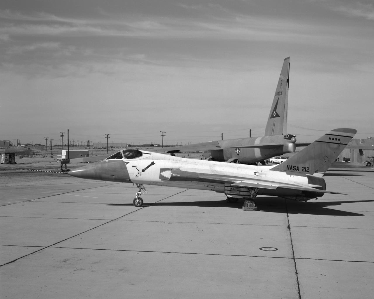
F5D Skylancer NASA 212 modified as the X-20 Dyna-Soar vision field simulator.
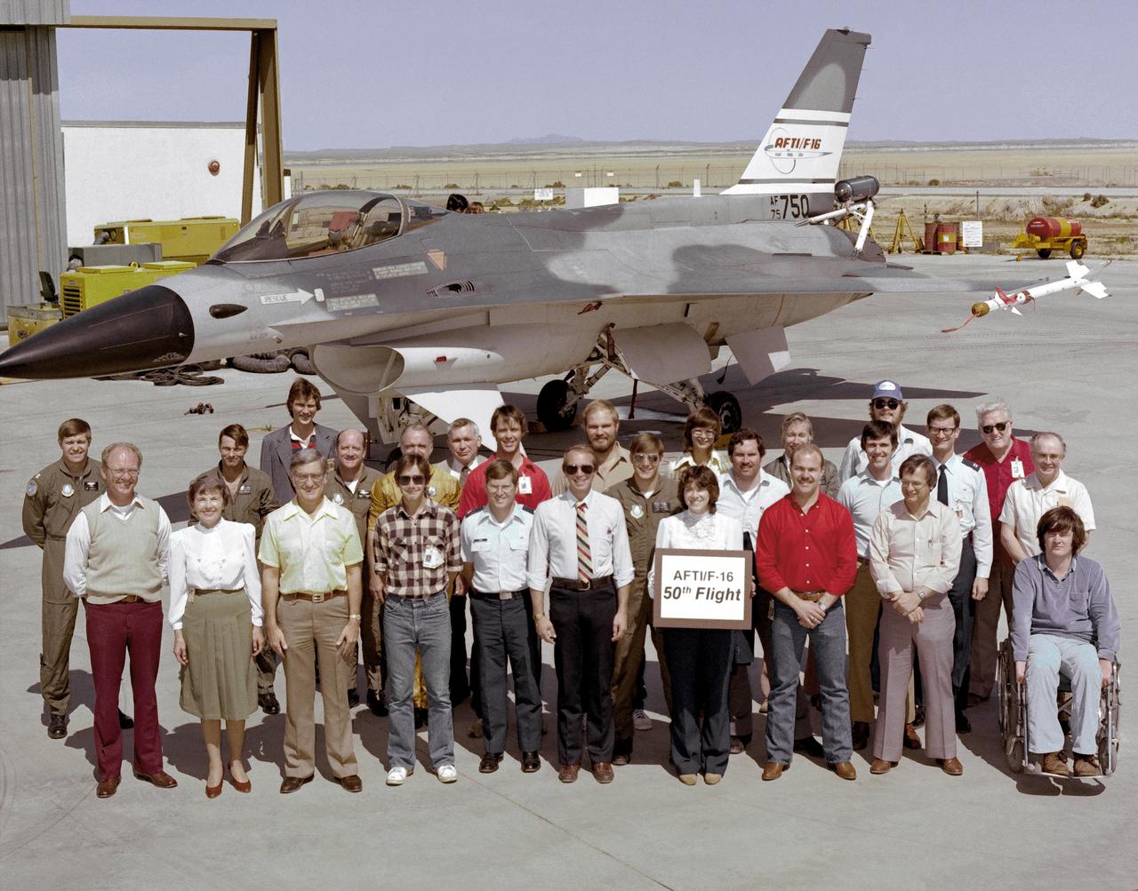
An early (1983) photograph of the AFTI F-16 team, commemorating the aircraft's 50th flight. It shows the initial configuration and paint finish of the AFTI F-16, as well as the forward mounted canards and the spin chute.