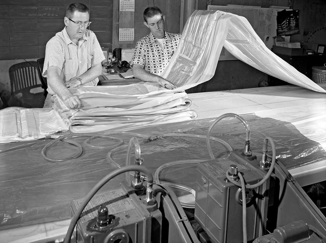
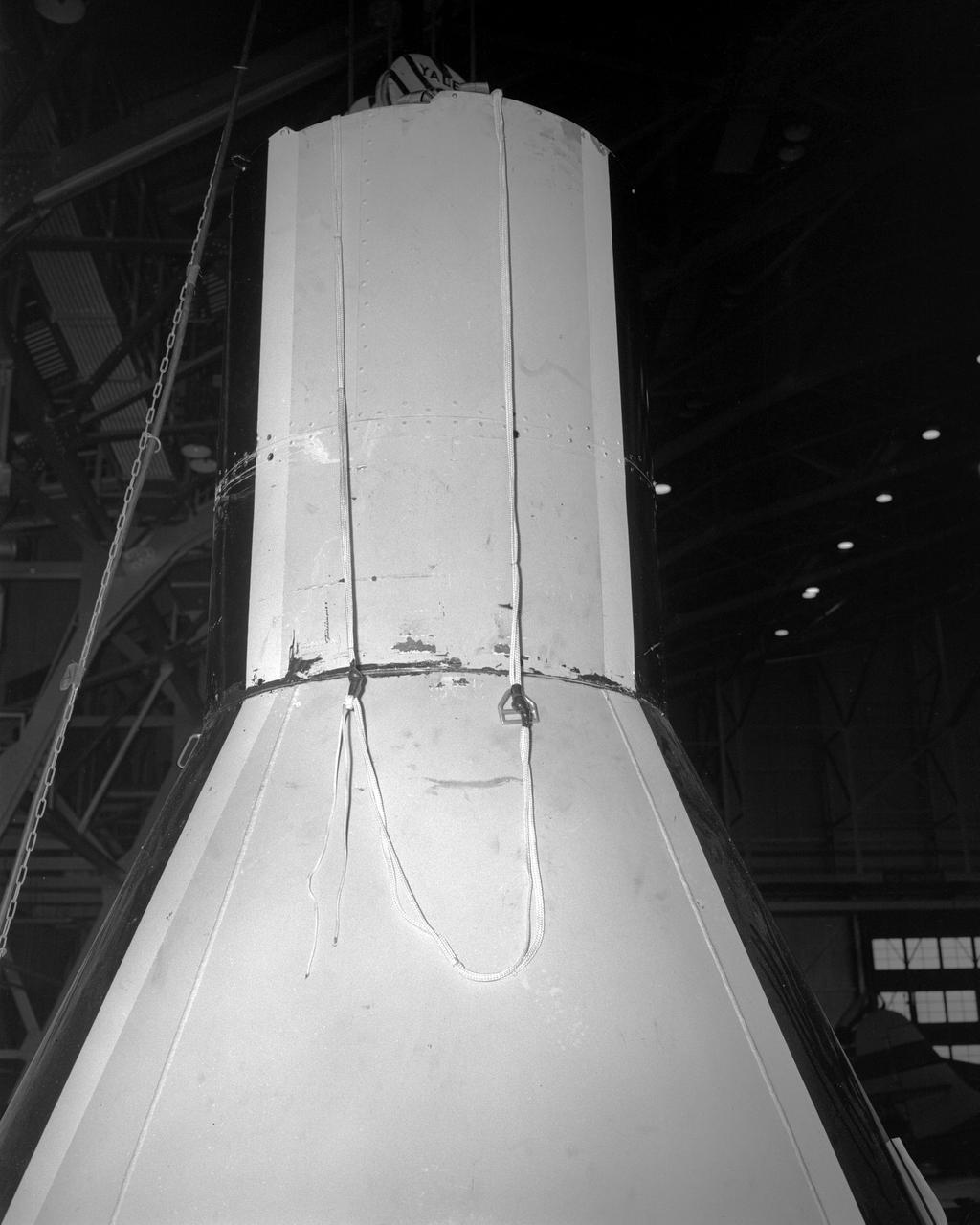
100' Satellite Packaging of Echo
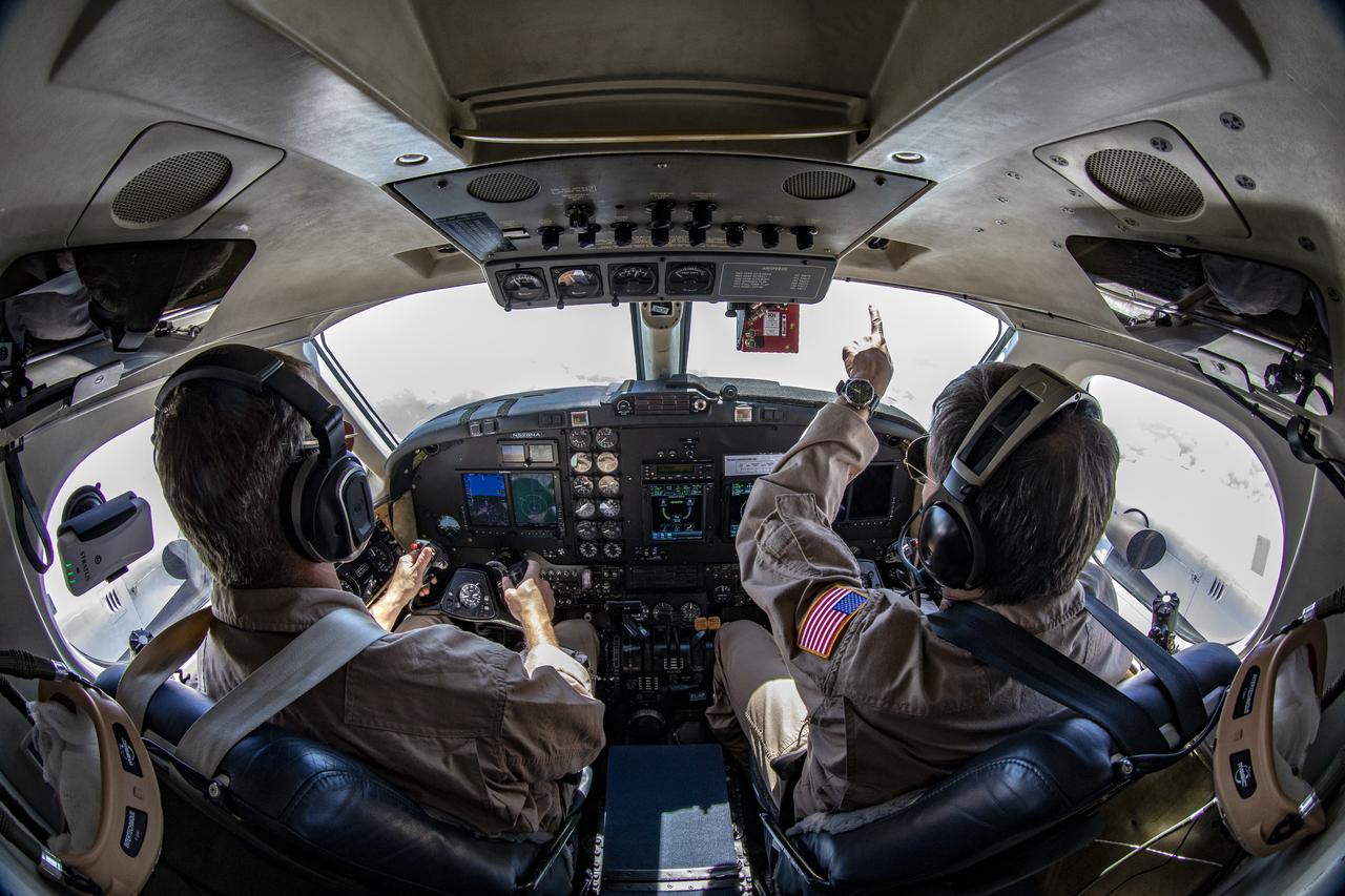
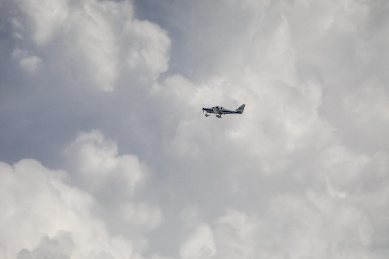
Testing the External Vision System (XVS) software on the B200 King Air. Pilots, Peter Coen and Wayne Ringelberg attempt to spot an incoming aircraft on the XVS monitor.
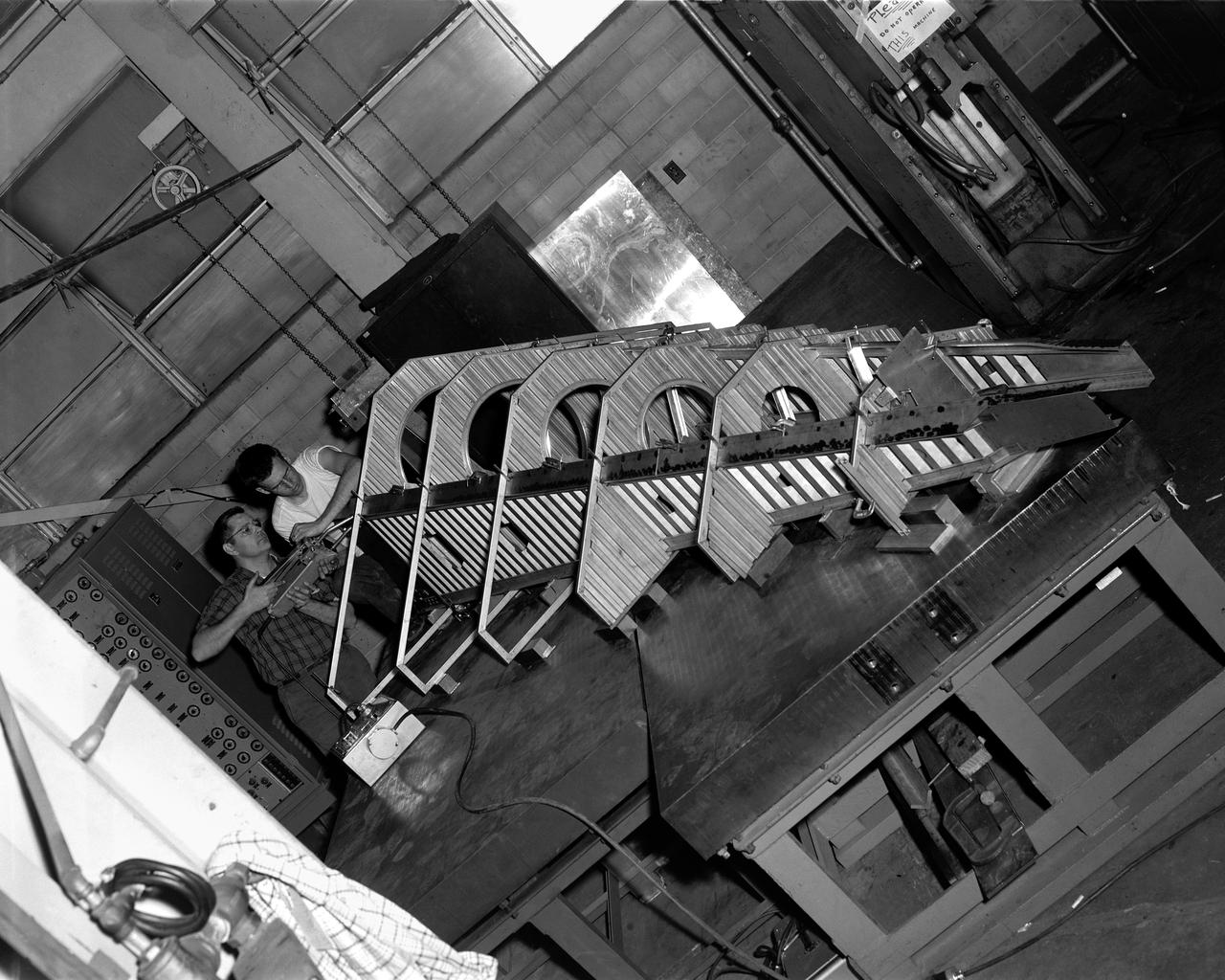
Research Model in the 7x10 High Speed Tunnel Building 1212B 300 mph tunnel
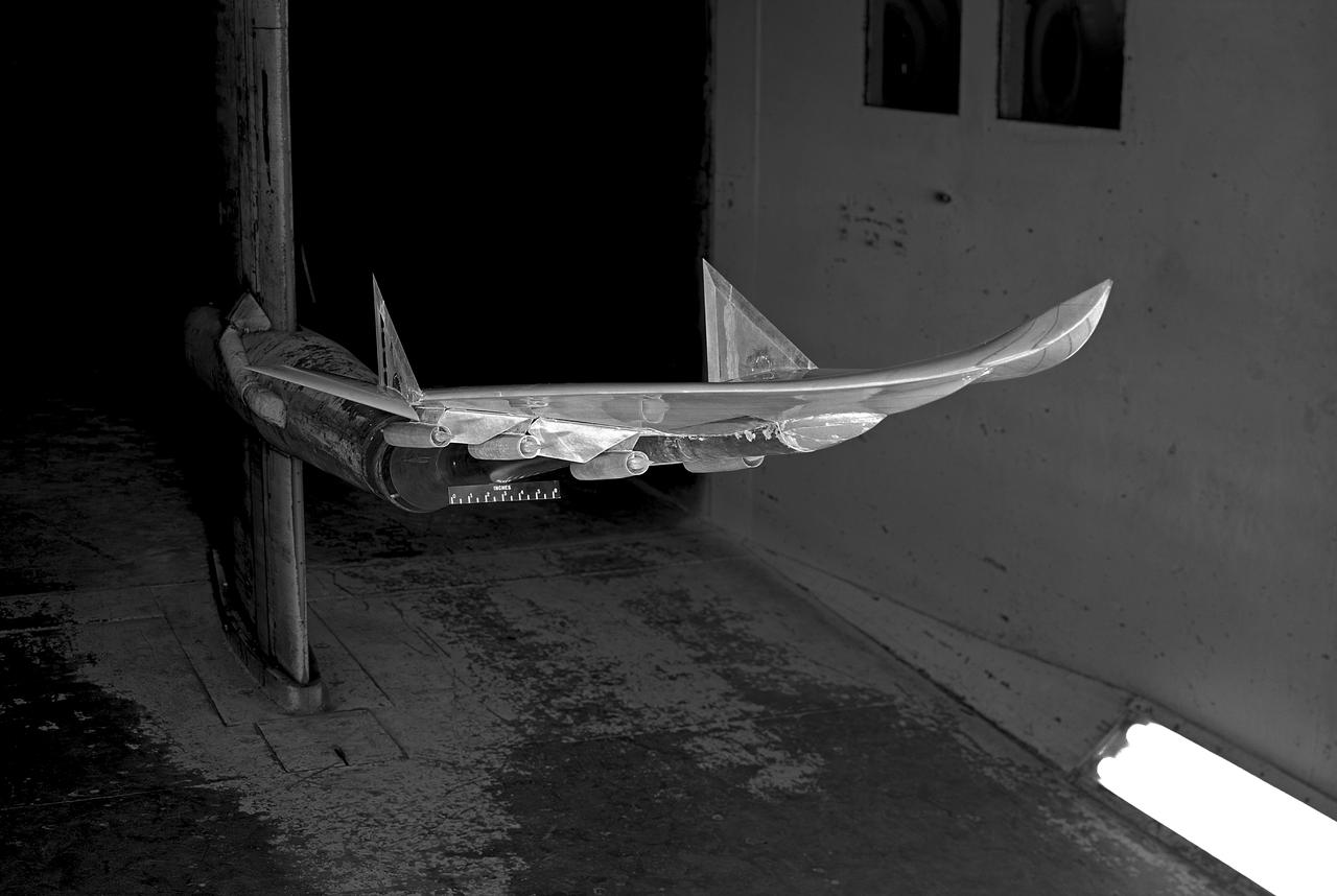
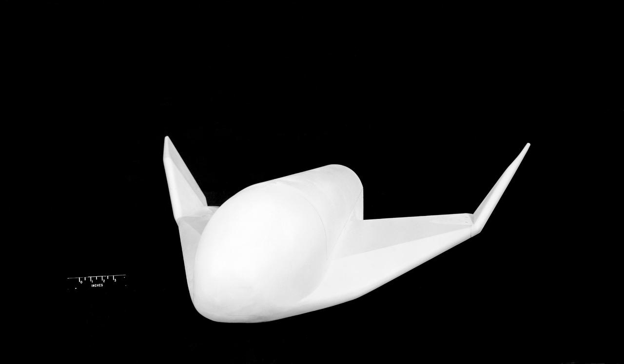
Boost glide model
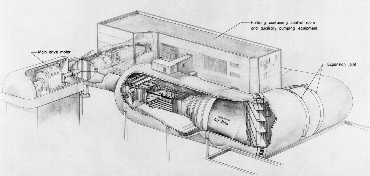
Drawing of the 8-Foot Transonic Pressure Tunnel.
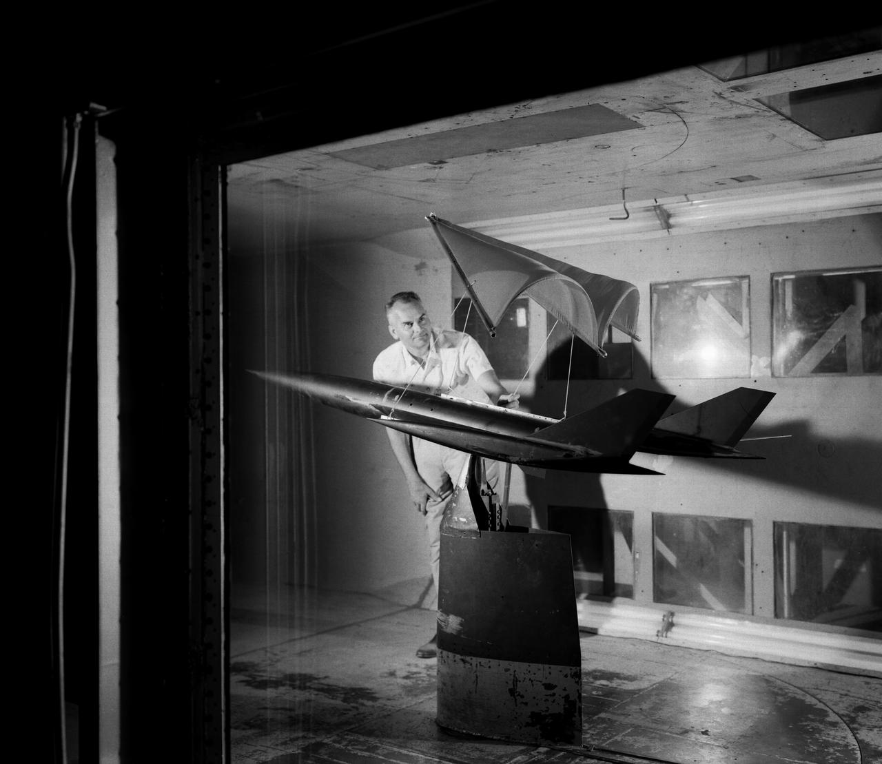
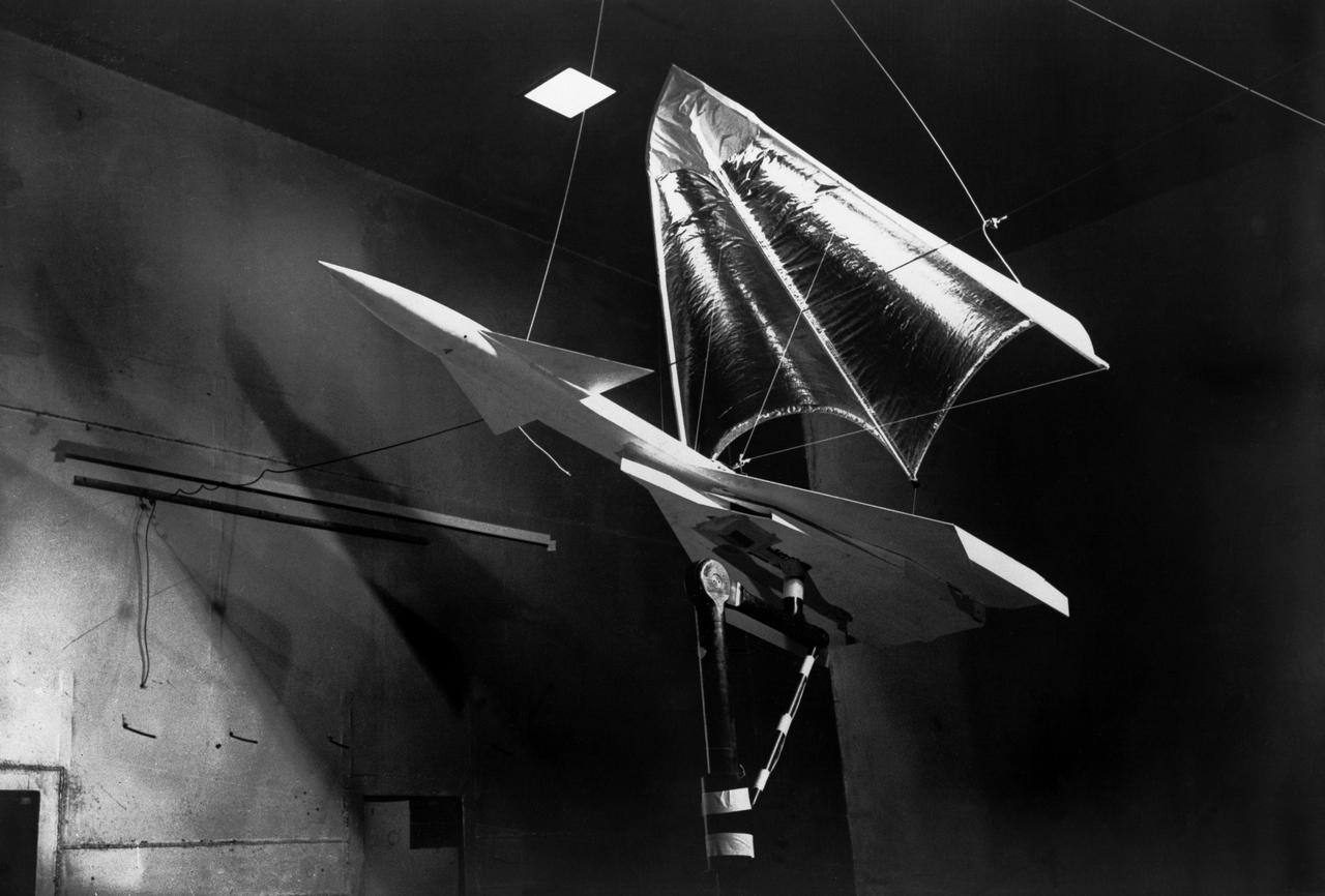
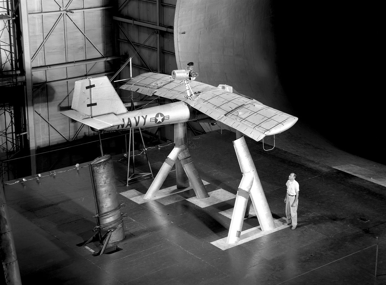
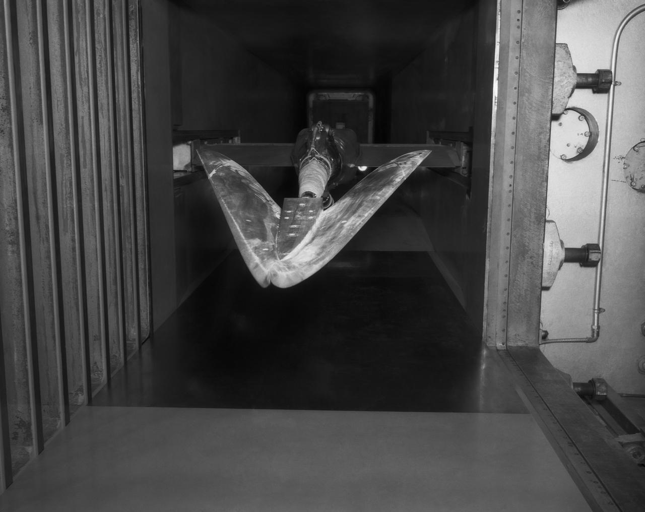
On June 26, 1959, then-Langley-research Francis Rogallo examined the Rogallo wing in the 7x10 FT Tunnel. Originally conceived as a means of bringing manned spacecraft to controlled, soft landings, Rogallo's concept was avidly embraced by later generations of hang-gliding enthusiasts. -- Photograph published in Winds of Change, 75th Anniversary NASA publication (page 18), by James Schultz.

FDCD Branch Stability and Control branch: Names, rows front to back, people left to right: Ground level: 1. ?? 2. Debra L. Livingston 3. Katherine G. Johnson 4. Robert Dunning Step 1: 1. Ellie Fillmore (?) 2. Al Hamer 3. Suresh Joshi Step 2: 1. John Young 2. Ernest Armstrong 3. Vladislav Klein 4. Charles T. Woolley Step 3: 1. Lawrence Taylor 2. Tony Fontana Step 4: 1. Bill Suit 2. Jane Carpenter 3. Daniel P. Giesy 4. Mario Smith Step 5: 1. Albert Schy 2. Ray Montgomery 3. Sahajendra Singh Top level: 1: Jim Batterson 2. Jim Williams 3. Claude Keckler 4. N. Sundararajan Behind all: John Shebalin Names given by Danial P. Giesy

Testing of the External Vision System (EVS) Software on the B200 King Air
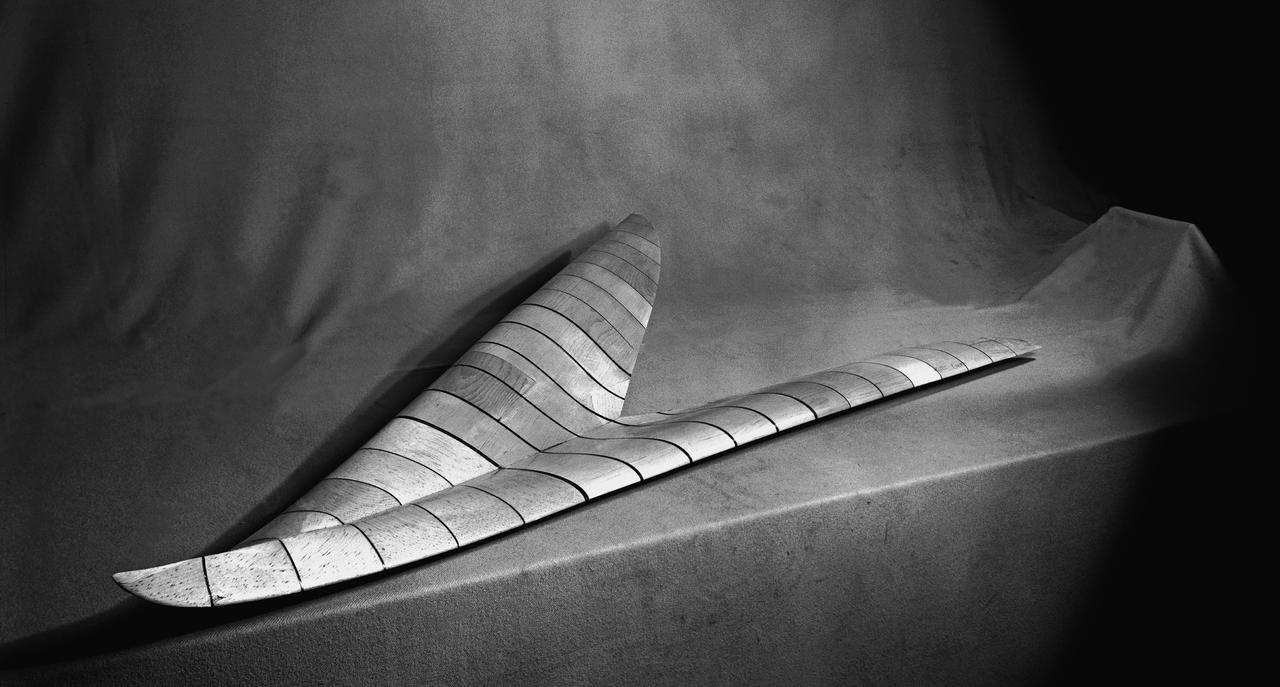
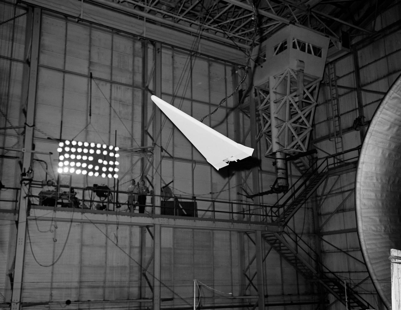
Wood Mock-up of Arrow Wing Bomber to Show Wing Contours
First test flight testing the visual display for the X59. The XVS display is aboard the B200 and the camera is mounted on the nose of the aircraft and inside the cockpit.

X-15 launch techniques were investigated using on-twentieth scale models mounted in the 7x10 FT Tunnel. -- Photograph published in Winds of Change, 75th Anniversary NASA publication (page 67), by James Schultz. -- Photograph also published in Sixty Years of Aeronautical Research 1917-1977 - a NASA publication (page 49), by David A. Anderton.
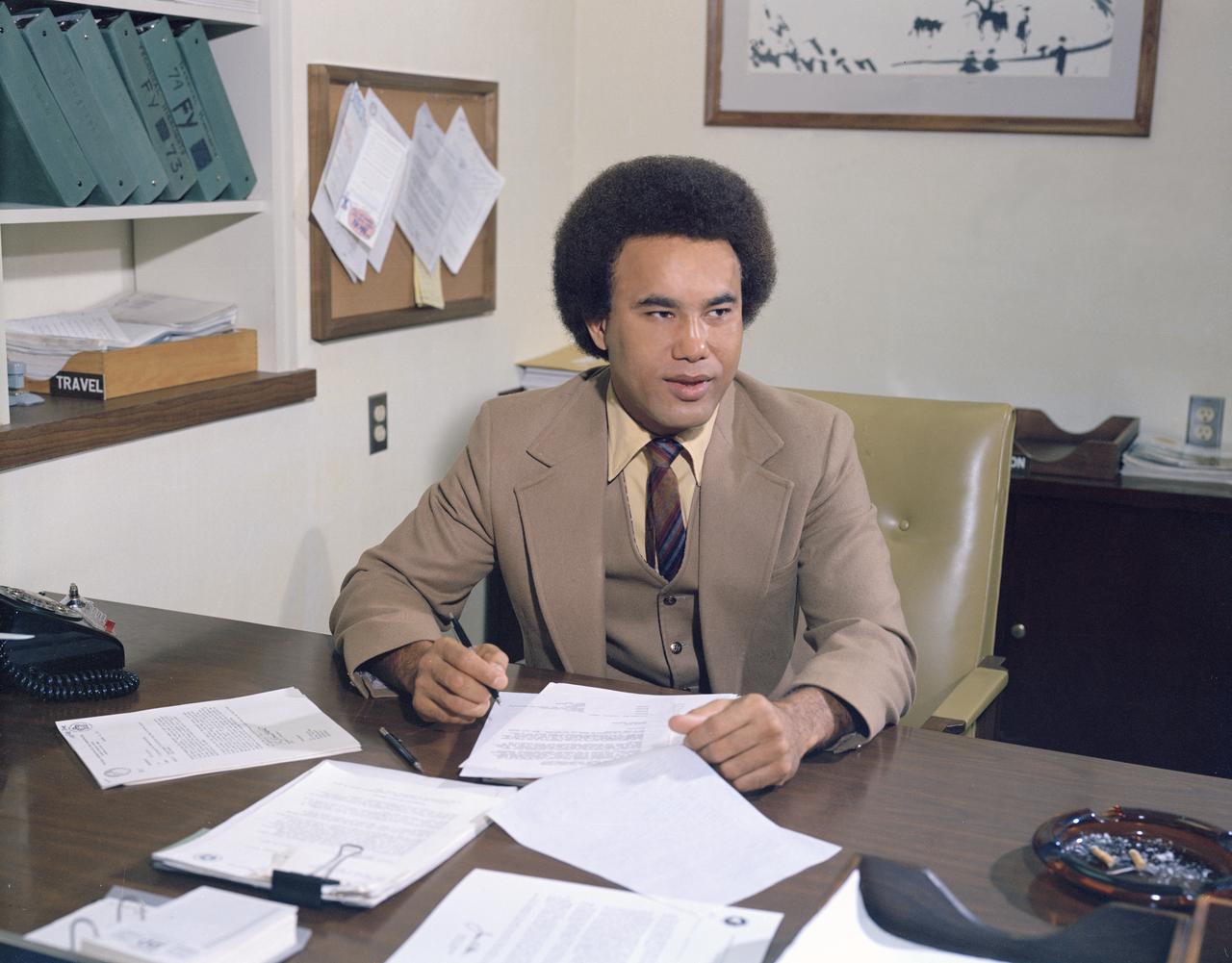
Minority Professionals at NASA Langley Research Center Samuel J. Scott at his desk working in the Office of Director for Structures, Staff Assistant.
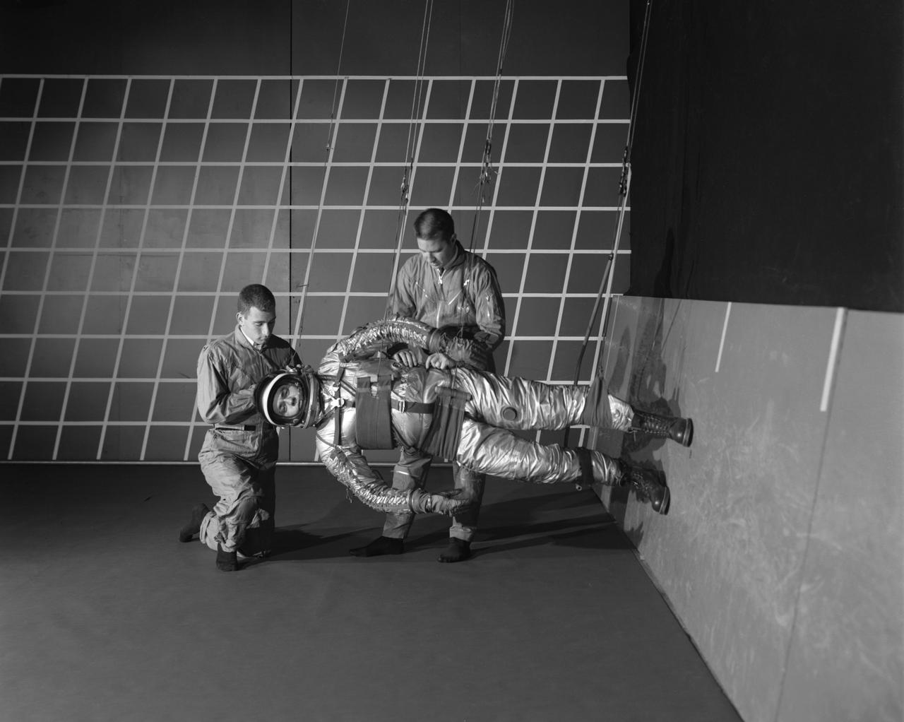
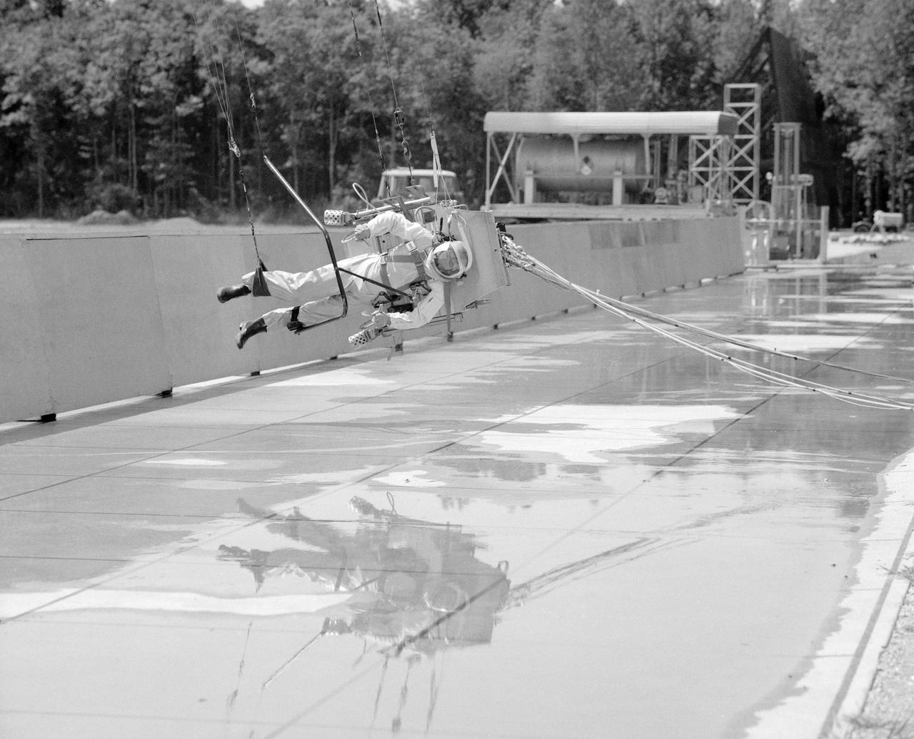
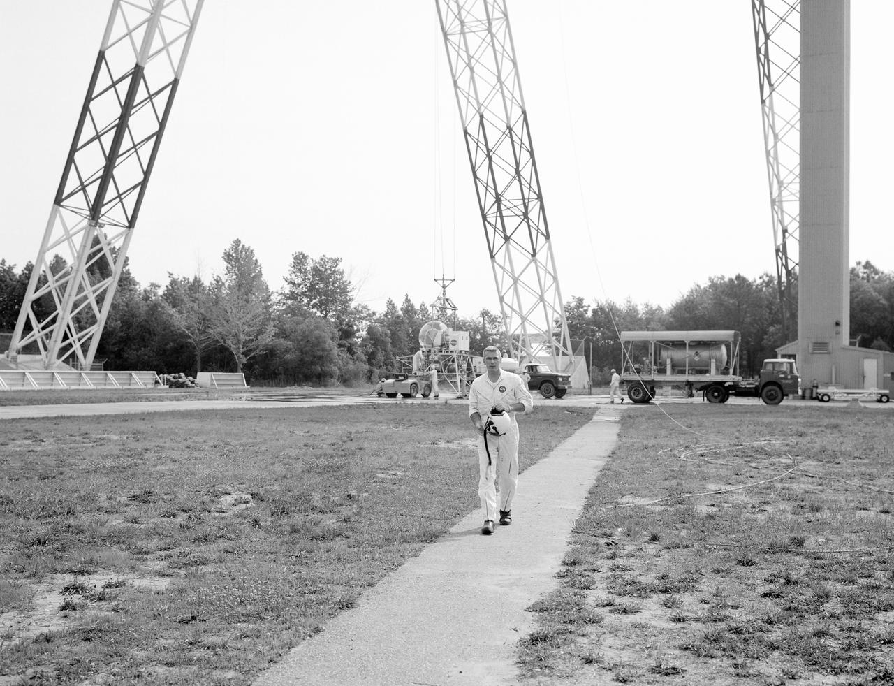
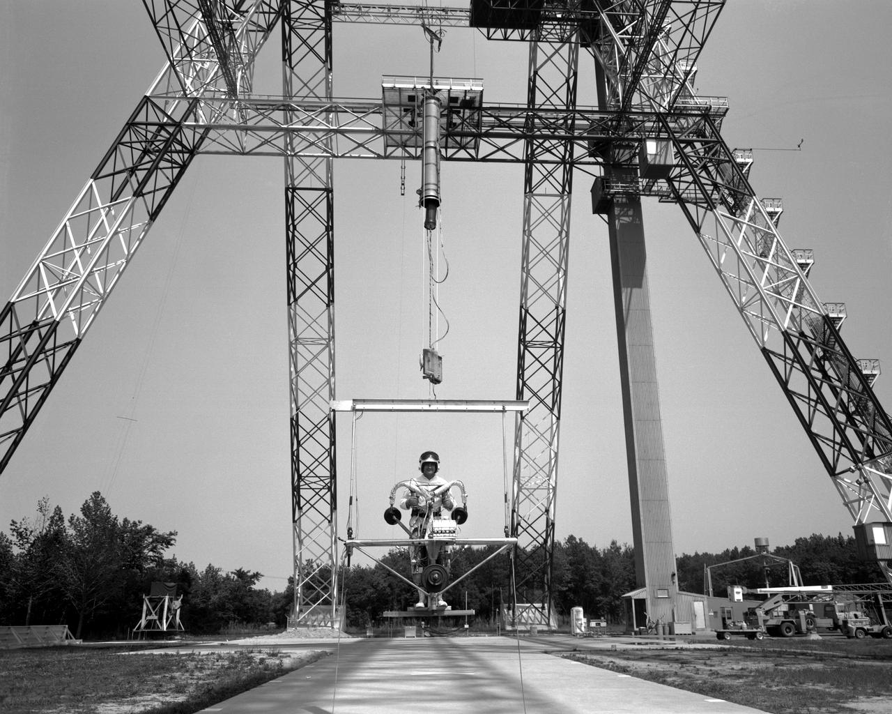
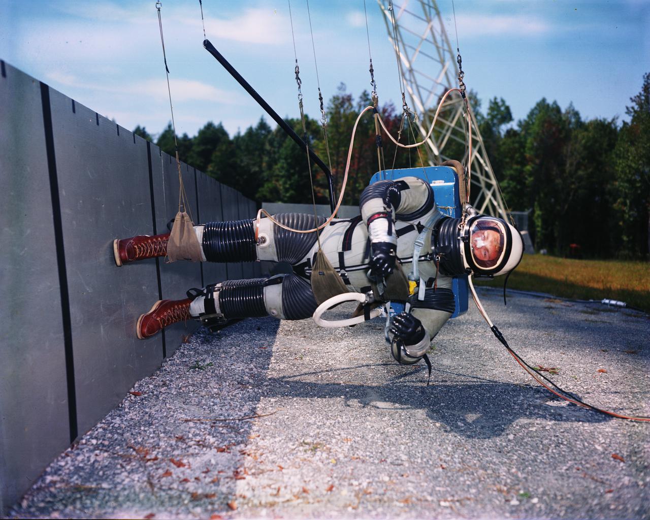
A test subject being suited up for studies on the Reduced Gravity Walking Simulator located in the hangar at Langley Research Center. The initial version of this simulator was located inside the hangar. Later a larger version would be located at the Lunar Landing Facility. The purpose of this simulator was to study the subject while walking, jumping or running. Researchers conducted studies of various factors such as fatigue limit, energy expenditure, and speed of locomotion. Francis B. Smith wrote in his paper "Simulators For Manned Space Research," "I would like to conclude this talk with a discussion of a device for simulating lunar gravity which is very effective and yet which is so simple that its cost is in the order of a few thousand dollars at most, rather than hundreds of thousands. With a little ingenuity, one could almost build this type simulator in his backyard for children to play on. The principle is ...if a test subject is suspended in a sling so that his body axis makes an angle of 9 1/2 degrees with the horizontal and if he then "stands" on a platform perpendicular to his body axis, the component of the earth's gravity forcing him toward the platform is one times the sine of 9 1/2 degrees or approximately 1/6 of the earth's normal gravity field. That is, a 180 pound astronaut "standing" on the platform would exert a force of only 30 pounds - the same as if he were standing upright on the lunar surface." -- Published in James R. Hansen, Spaceflight Revolution: NASA Langley Research Center From Sputnik to Apollo, NASA SP-4308; Francis B. Smith, "Simulators For Manned Space Research," Paper for 1966 IEEE International Convention, New York, NY, March 21-25, 1966

Phase SB Propeller installed on F88B
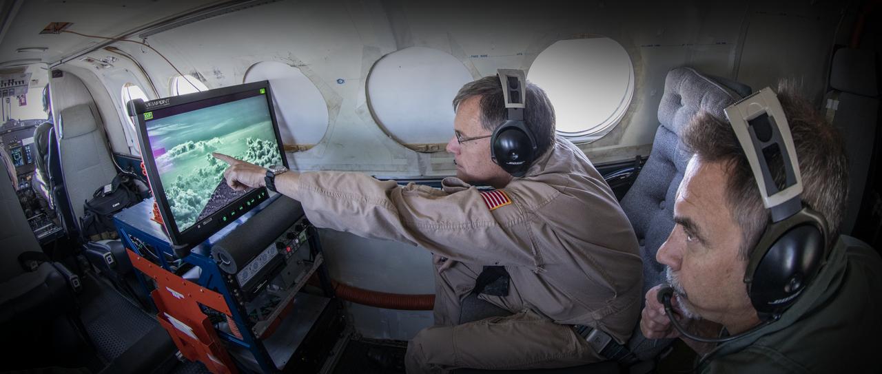
Testing the External Vision System (XVS) software on the B200 King Air. Pilots, Peter Coen and Wayne Ringelberg attempt to spot an incoming aircraft on the XVS monitor.
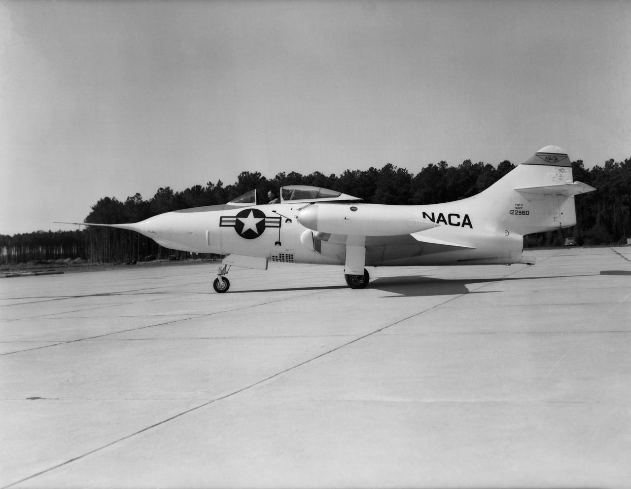
Grumman F9F-2 Panther: Originally built as a F9F-3, this Grumman F9F-2 Panther has a Pratt and Whitney J42 turbojet power plant, hence the designation change. This Panther underwent handling quality tests, serving long enough at Langley to witness the change from the NACA to NASA.
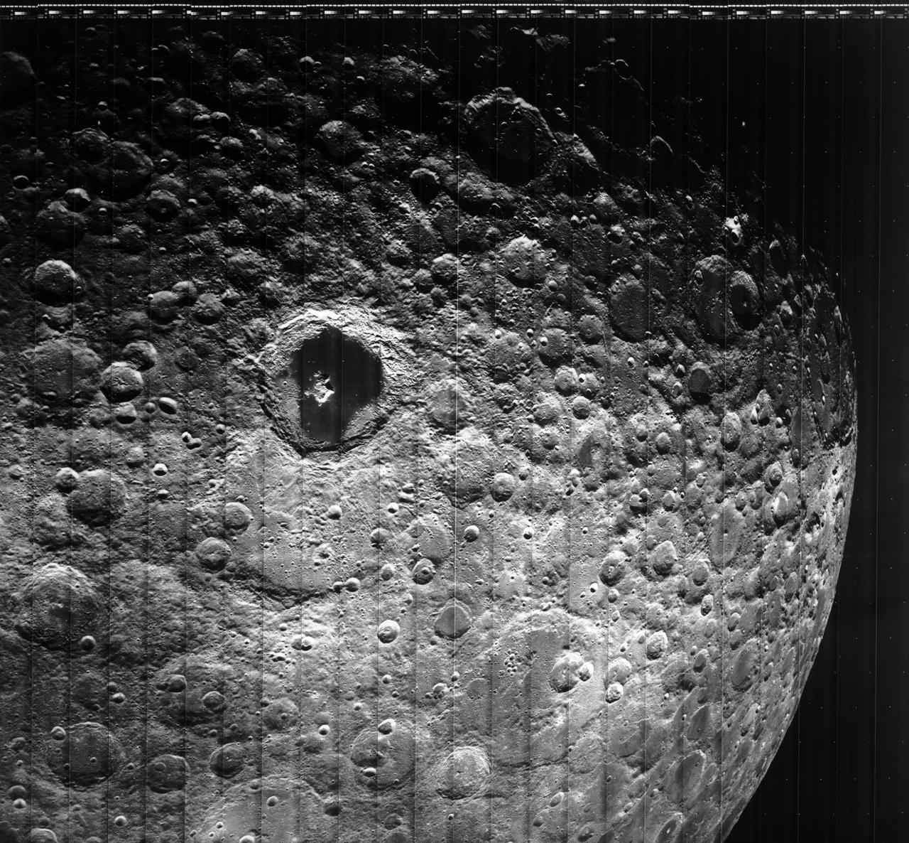
Moon Lunar Orbiter-Lunar Orbiter III: The hidden or dark side of the Moon was taken by Lunar Orbiter III During its mission to photograph potential lunar-landing sites for Apollo missions. -- Photograph published in Winds of Change, 75th Anniversary NASA publication (page 94), by James Schultz. Photo Number:67-H-328 is 1967-L-04026
Vehicles and Missions Studies Charts, Space Capsule
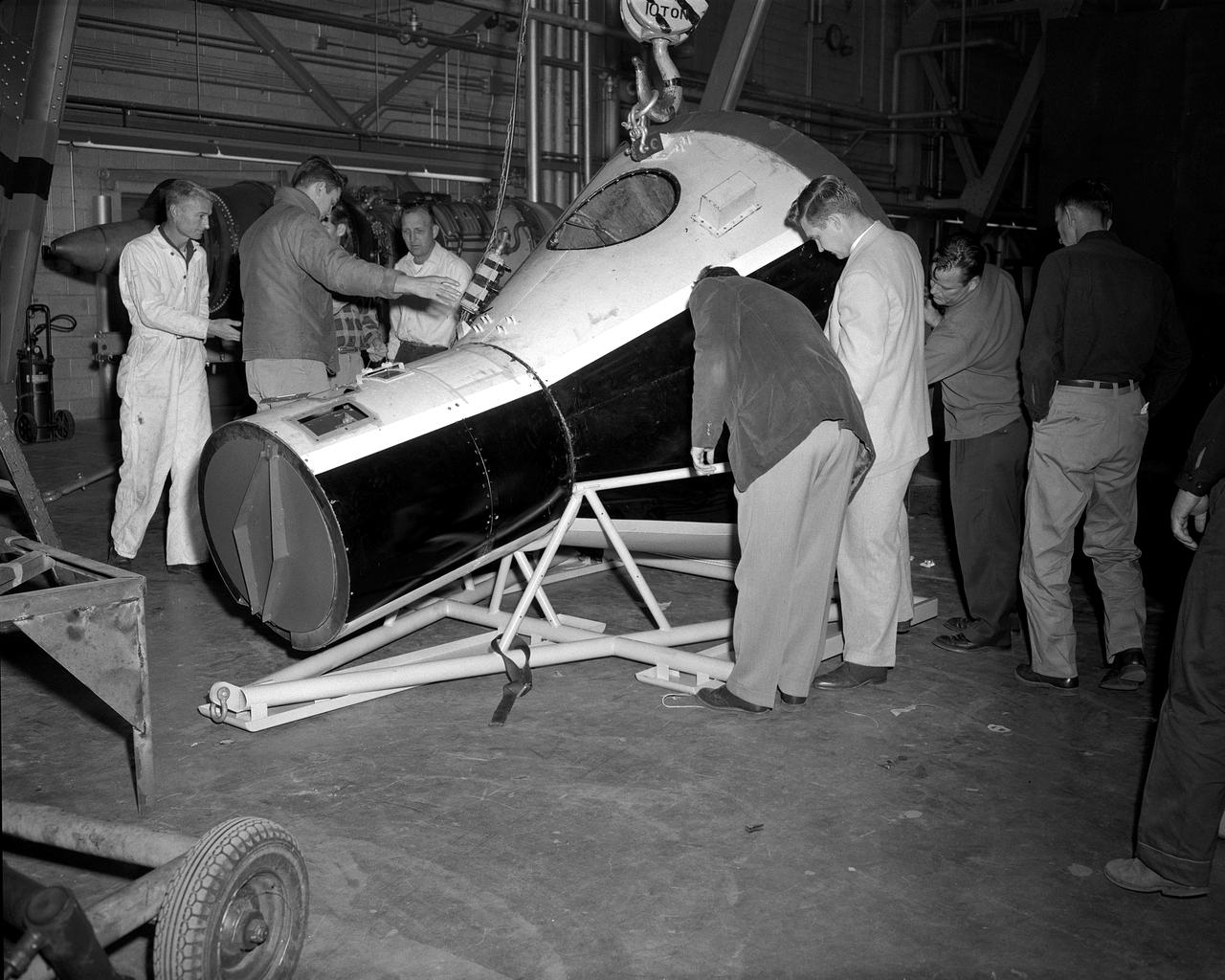
Assembling the Little Joe capsules. The capsules were manufactured in-house by Langley technicians. Three capsules are shown here in various stages of assembly. The escape tower and rocket motors shown on the completed capsule would be removed before shipping and finally assembly for launching at Wallops Island. Joseph Shortal wrote (vol. 3, p. 32): Design of the Little Joe capsules began at Langley before McDonnell started on the design of the Mercury capsule and was, therefore, a separate design. Although it was not designed to carry a man, it did have to carry a monkey. It had to meet the weight and center of gravity requirements of Mercury and withstand the same aerodynamic loads during the exit trajectory. Although in comparison with the overall Mercury Project, Little Joe was a simple undertaking, the fact that an attempt was made to condense a normal two-year project into a 6-month one with in house labor turned it into a major undertaking for Langley. Project Mercury: Little Joe: Boilerplate Mercury spacecraft undergo fabrication at the shops of the Langley Research Center. They will launched atop Little Joe rockets to test the spacecraft recovery systems. -- Published in Joseph A. Shortal, History of Wallops Station: Origins and Activities Through 1949, (Wallops Island, VA: National Aeronautics and Space Administration, Wallops Station, nd), Comment Edition. L59-4947 Technicians prepare a Little Joe launch vehicle prototype for the Mercury space program, 1959. Photograph published in Winds of Change, 75th Anniversary NASA publication, page 76, by James Schultz

Richard F. Gordon Jr. climbing into training simulator. Astronaut Richard (Dick) Gordon, died in November 2017, at his home in California. He was 88. Gordon orbited the Moon on Apollo 12 in 1969 while two other astronauts walked on it. The Apollo 12 crew capsule can be seen at Langley's official visitor center, the Virginia Air and Space Center in Hampton VA. NASA 2017 Annual report, Celebrating 100 years.page 23 Milestones.

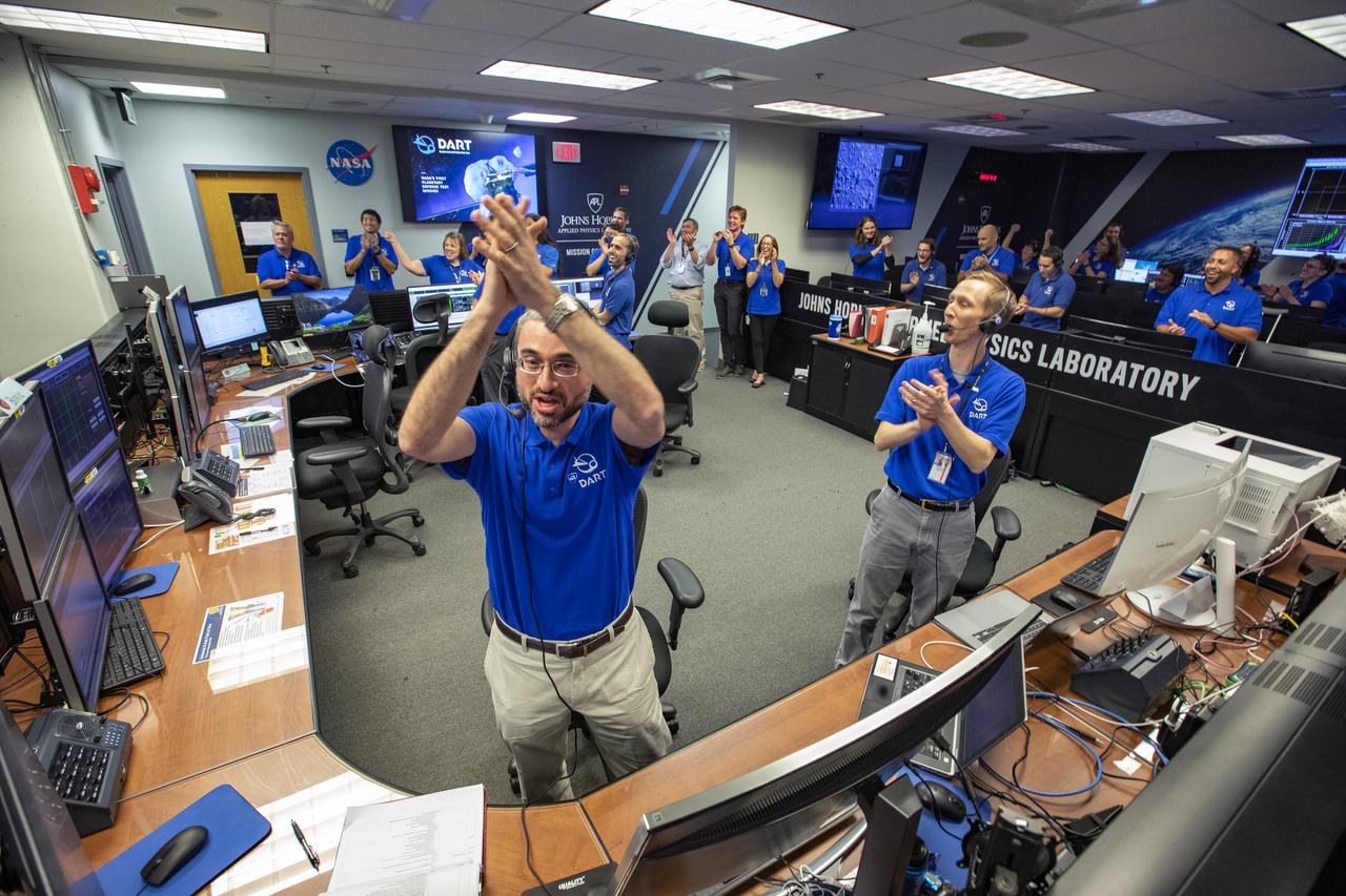
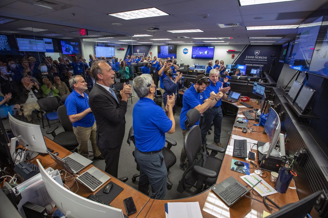
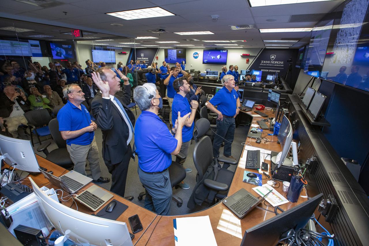
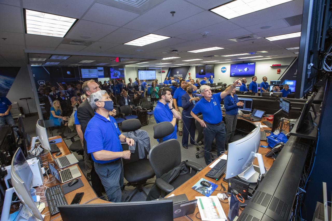
NASA’s Double Asteroid Redirection Test (DART) command team at Johns Hopkins University, Applied Physics Laboratory monitoring the DART spacecraft’s impact into the asteroid Dimorphos. The operation is the first of its kind test to redirect deadly asteroids from hitting Earth.
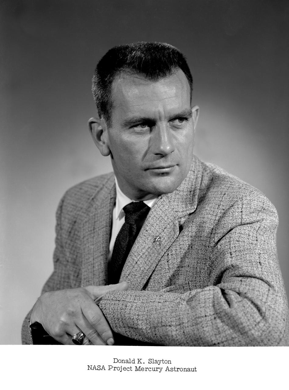
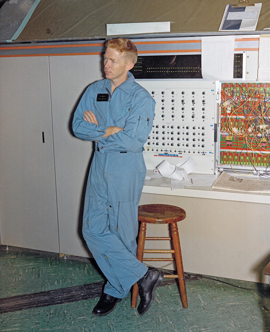
NASA Project Mercury astronaut -- Slayton was later known as Deke.
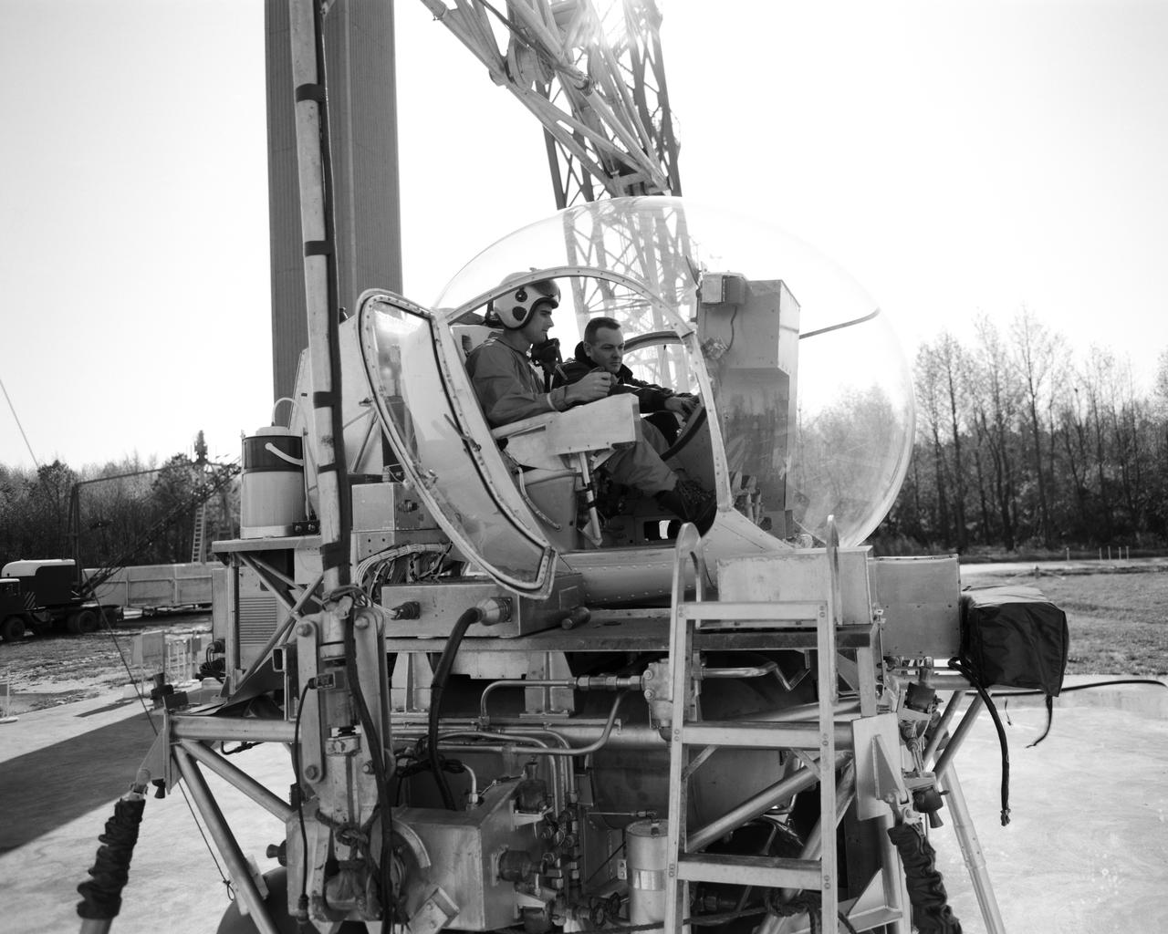
ICARUS - Lunar Walker with Pilot Dick Yenni. Yenni in ICARUS rig for jet propelled lunar mobility, at Lunar Landing Research Facility gantry.
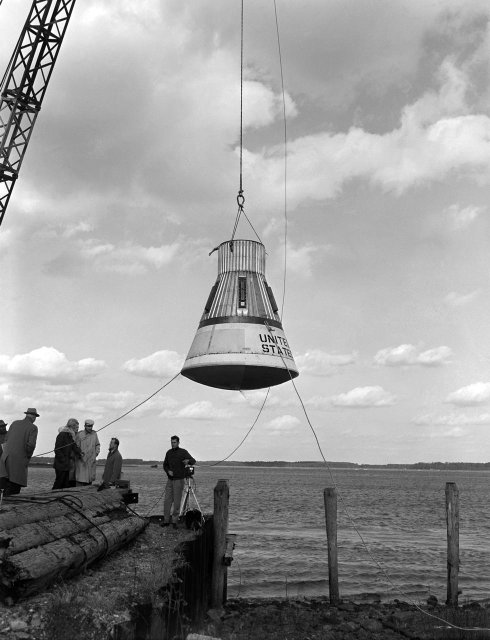
Water drop and recovery from shore-based crane at Langley's back river.
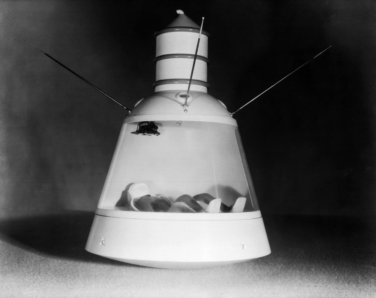
Scale model of Mercury capsule shape A, indicating the position of the astronaut.
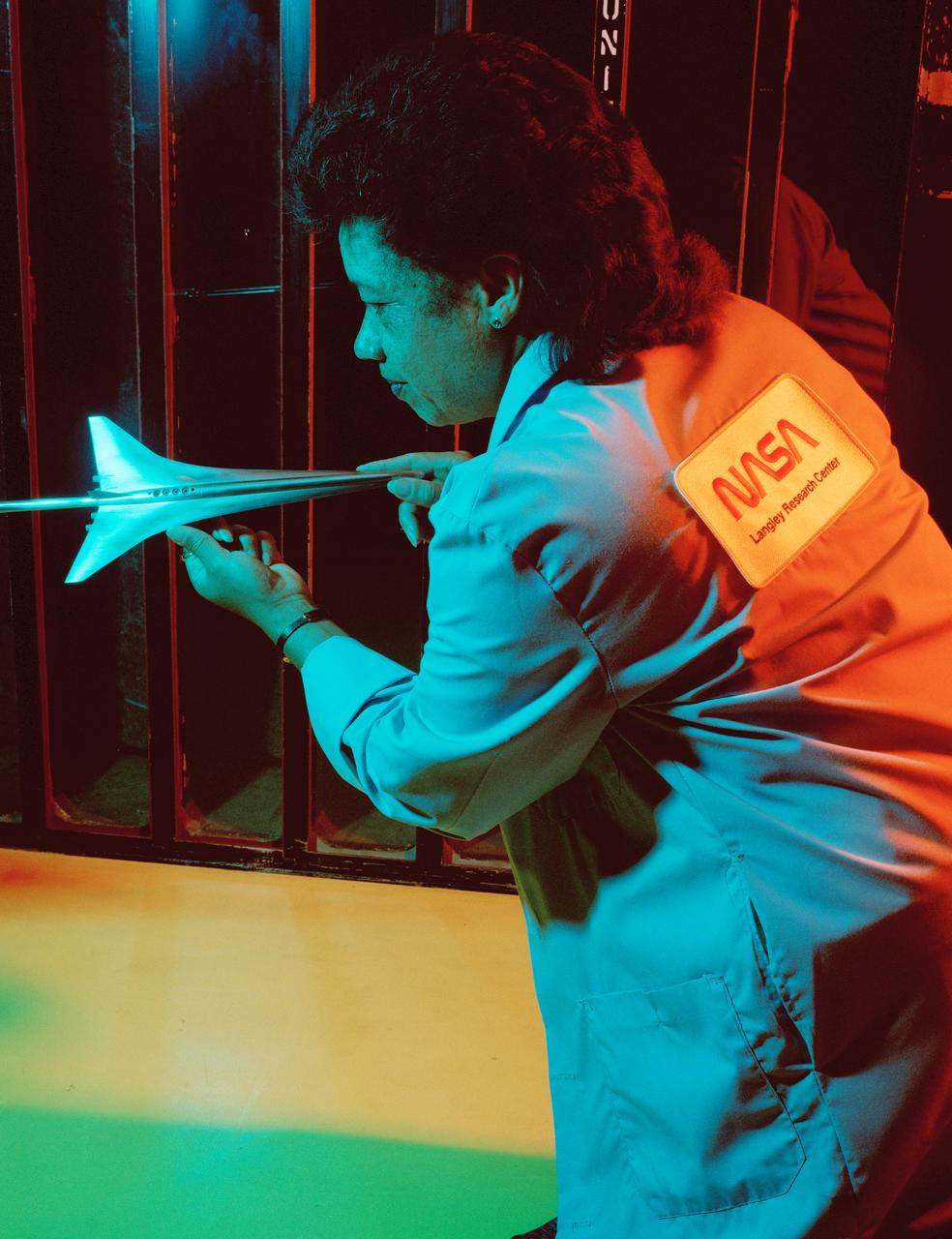
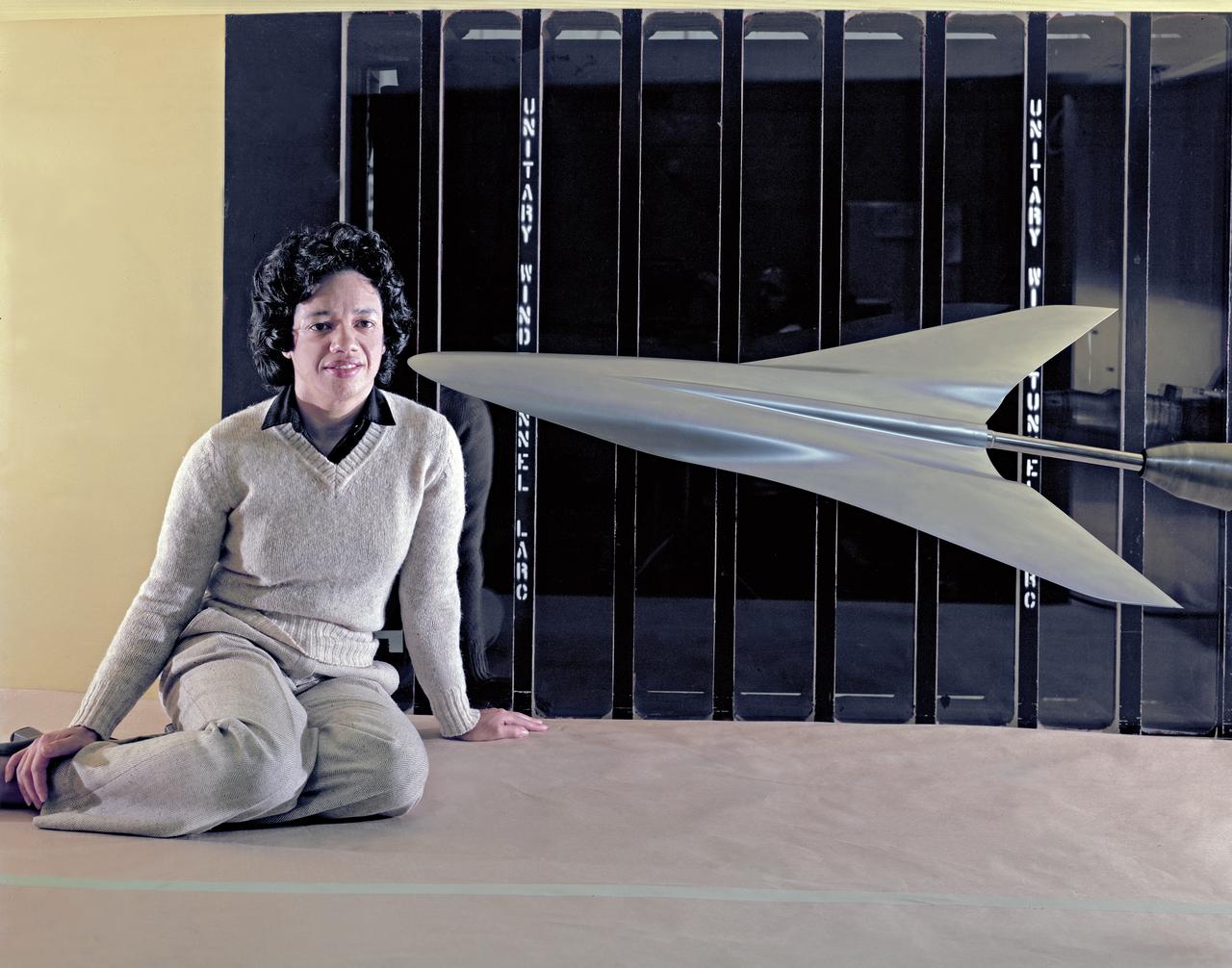
Low-boom Model Mach II in Unitary Tunnel with Christine Darden
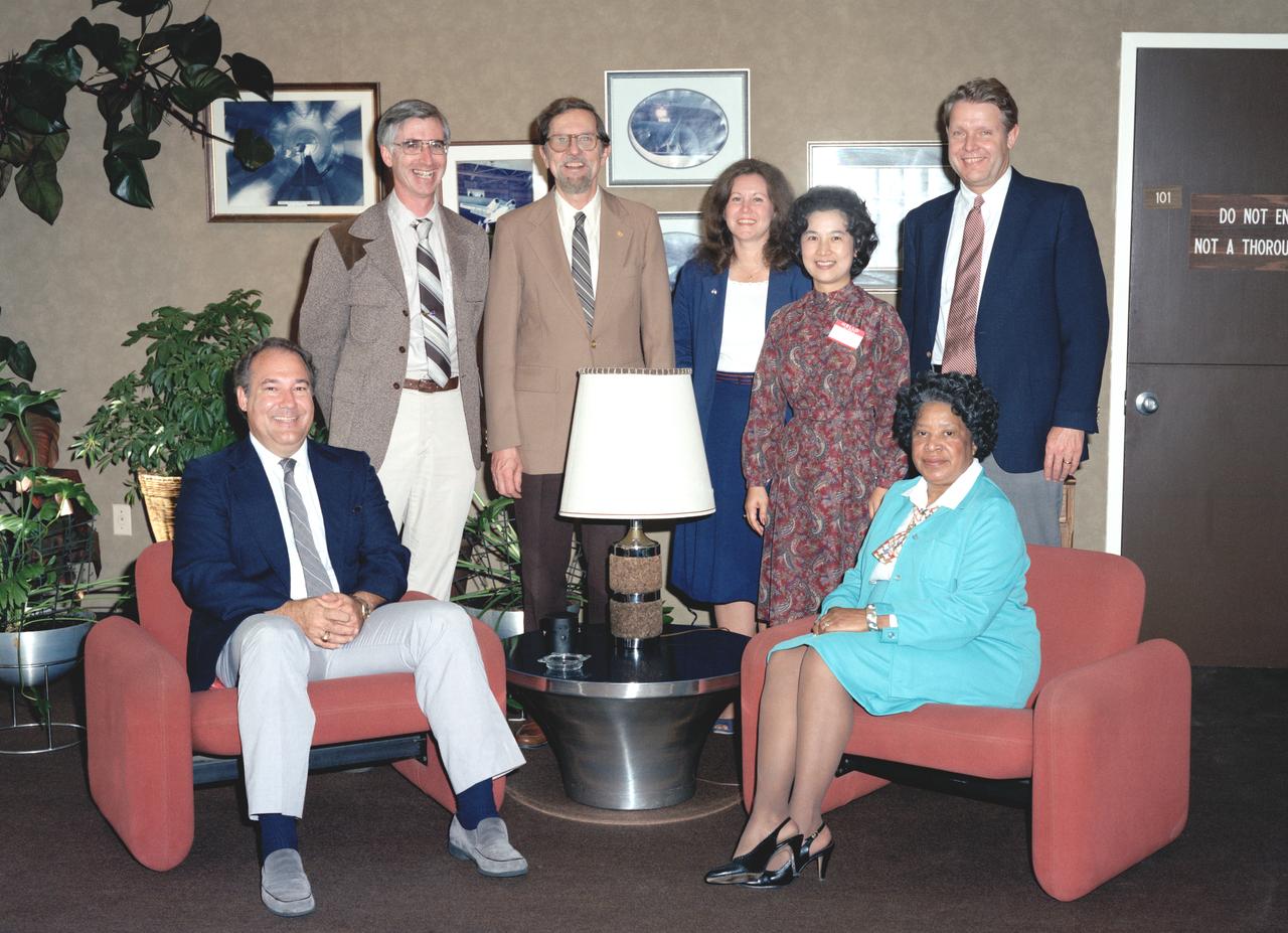
Federal Women's Program Mary Jackson setting. Center directors Donald Heath, and Richard Peterson. In 1958 Mary Jackson became NASA’s first black female engineer.
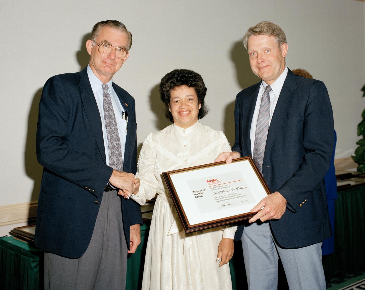
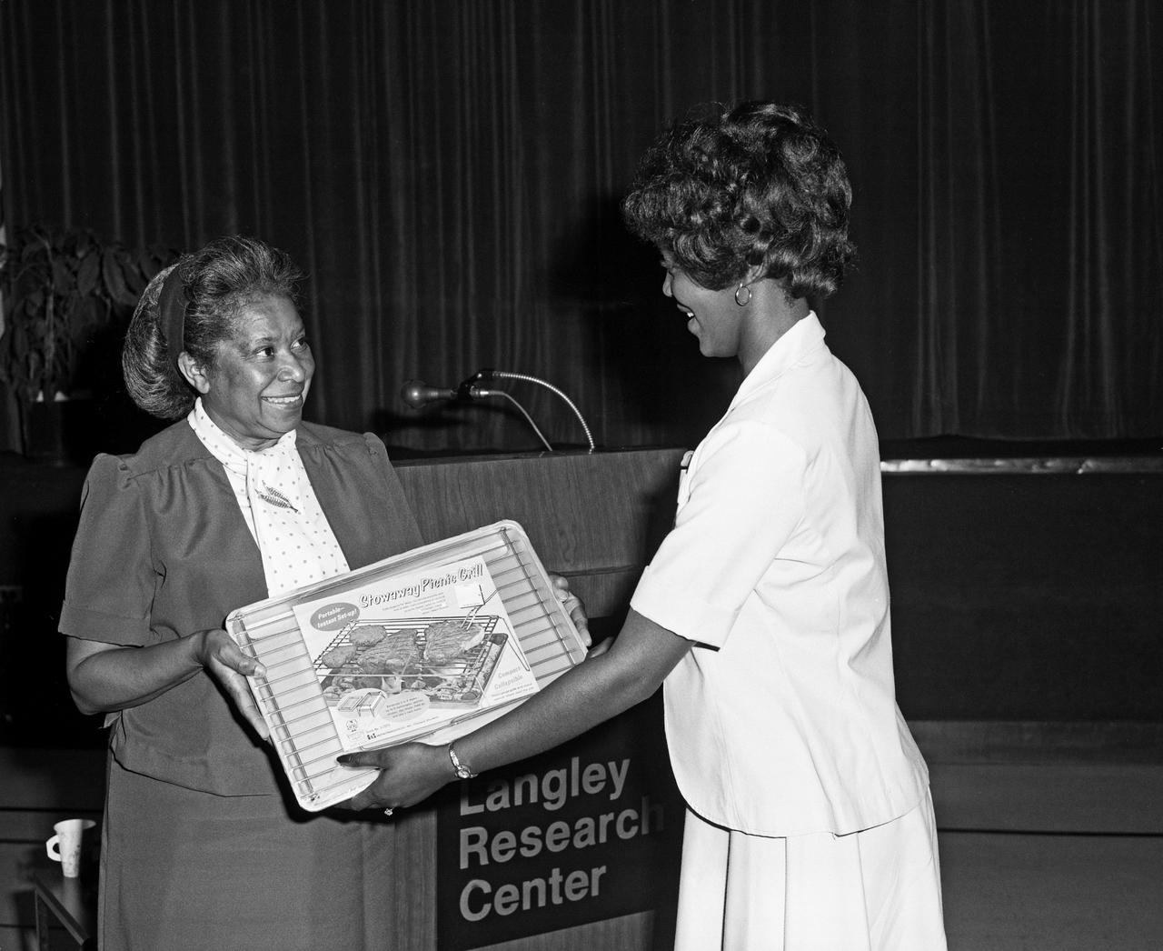
Technology Transfer Awards, Dr. Christine M. Darden, with Center Director Richard W. Peterson on the right.
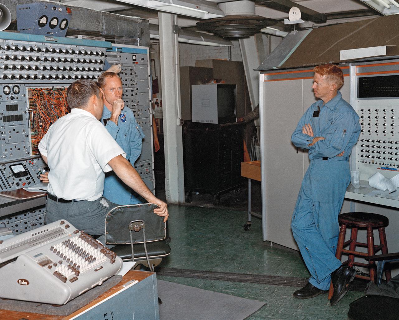
Astronaut Alan Shepard (right) was one of 14 astronauts, 8 NASA test pilots, and 2 McDonnell test pilots who took part in simulator studies. Shepard flew the simulator on November 14, 1963. A.W. Vogeley wrote: "Many of the astronauts have flown this simulator in support of the Gemini studies and they, without exception, appreciated the realism of the visual scene. The simulator has also been used in the development of pilot techniques to handle certain jet malfunctions in order that aborts could be avoided. In these situations large attitude changes are sometimes necessary and the false motion cues that were generated due to earth gravity were somewhat objectionable; however, the pilots were readily able to overlook these false motion cues in favor of the visual realism." Roy F. Brissenden noted that: "The basic Gemini control studies developed the necessary techniques and demonstrated the ability of human pilots to perform final space docking with the specified Gemini-Agena systems using only visual references. ... Results... showed that trained astronauts can effect the docking with direct acceleration control and even with jet malfunctions as long as good visual conditions exist.... Probably more important than data results was the early confidence that the astronauts themselves gained in their ability to perform the maneuver in the ultimate flight mission." Shepard commented: "I had the feeling tonight - a couple of times - that I was actually doing the space mission instead of the simulation. As I said before, I think it is a very good simulation." Shepard also commented on piloting techniques. Most astronauts arrived at this same preferred technique: Shepard: "I believe I have developed the preferred technique for these conditions and the technique appeared to me to be best was to come in slightly above the target so that I was able to use the longitudinal marks on the body of the target as a reference, particularly for a lateral translation and, of course, I used the foreshortening effect for a vertical translation, and this appeared to give me the best results. By that I mean the least number of control motions and the lowest fuel usage and the best end techniques, or the best end conditions, I should say." Engineer: "When you started to run you didn't start thrusting immediately I don't believe. It looked like you started working on your attitudes, then started closing in." Shepard: "That is correct. I did that because I felt that I wanted to get the X-axis translation in the most effective vector and for minimum fuel usage that wouldn't introduce any other lateral or vertical offsets that did not already exist." -- Published in Barton C. Hacker and James M. Grimwood, On the Shoulders of Titans: A History of Project Gemini, NASA SP-4203; A.W. Vogeley, "Discussion of Existing and Planned Simulators For Space Research," Paper presented at the Conference on the Role of Simulation in Space Technology, August 17-21, 1964; Roy F. Brissenden, "Initial Operations with Langley's Rendezvous Docking Facility," Langley Working Paper, LWP-21, 1964.
Apollo Astronaut Fred Haise visiting NASA Langley historic gantry where Fred once trained to fly the lunar lander.
Astronaut Eugene Cernan at Lunar Lander Research Facility. Cernan under gantry, in training module. Captain Cernan was one of fourteen astronauts selected by NASA in October 1963. On his second space flight, he was lunar module pilot of Apollo 10, May 18-26, 1969, the first comprehensive lunar-orbital qualification and verification flight test of an Apollo lunar module.
Canard model
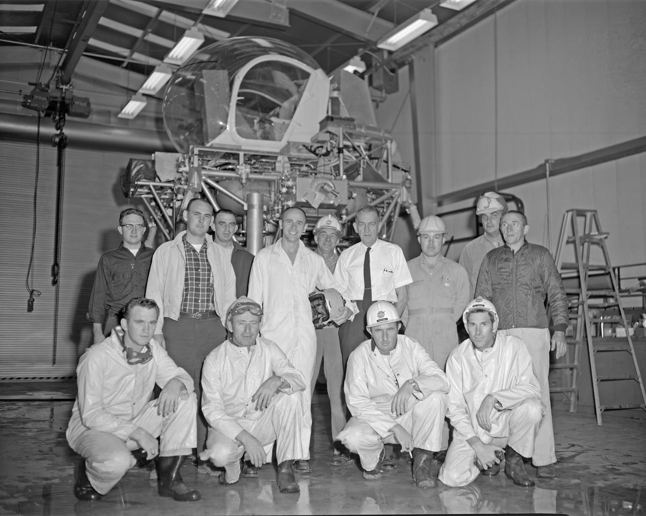
Astronaut Allen Bean with Lunar Landing Research Facility (LLRF) crew. Alan Bean was one of the third group of astronauts named by NASA in October 1963. He served as backup astronaut for the Gemini 10 and Apollo 9 missions.
Multiple exposure of Rendezvous Docking Simulator. Francis B. Smith, described the simulator as follows: The rendezvous and docking operation of the Gemini spacecraft with the Agena and of the Apollo Command Module with the Lunar Excursion Module have been the subject of simulator studies for several years. This figure illustrates the Gemini-Agena rendezvous docking simulator at Langley. The Gemini spacecraft was supported in a gimbal system by an overhead crane and gantry arrangement which provided 6 degrees of freedom - roll, pitch, yaw, and translation in any direction - all controllable by the astronaut in the spacecraft. Here again the controls fed into a computer which in turn provided an input to the servos driving the spacecraft so that it responded to control motions in a manner which accurately simulated the Gemini spacecraft. -- Published in Barton C. Hacker and James M. Grimwood, On the Shoulders of Titans: A History of Project Gemini, NASA SP-4203 Francis B. Smith, Simulators for Manned Space Research, Paper presented at the 1966 IEEE International convention, March 21-25, 1966.
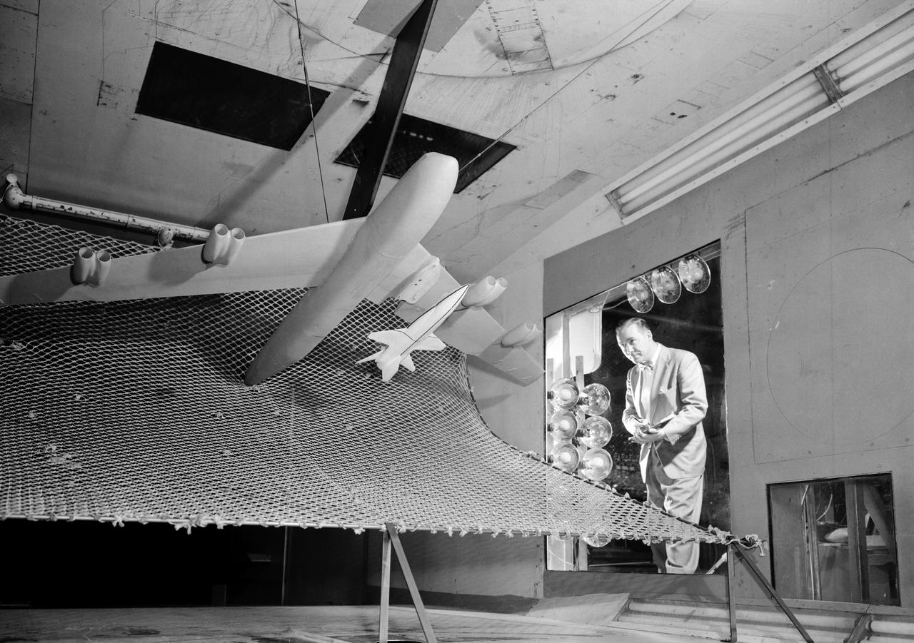
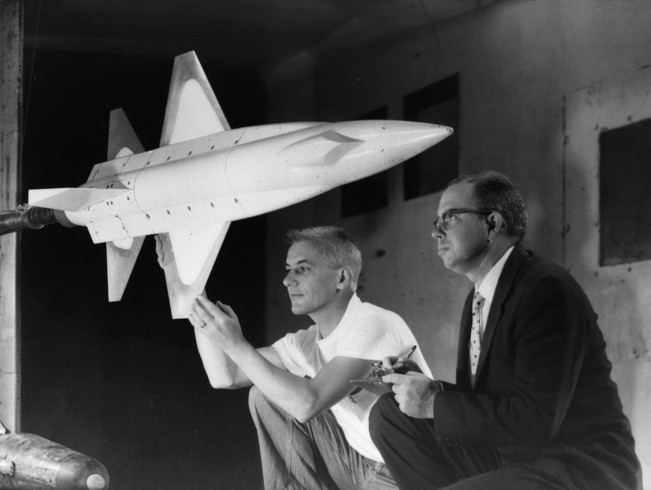
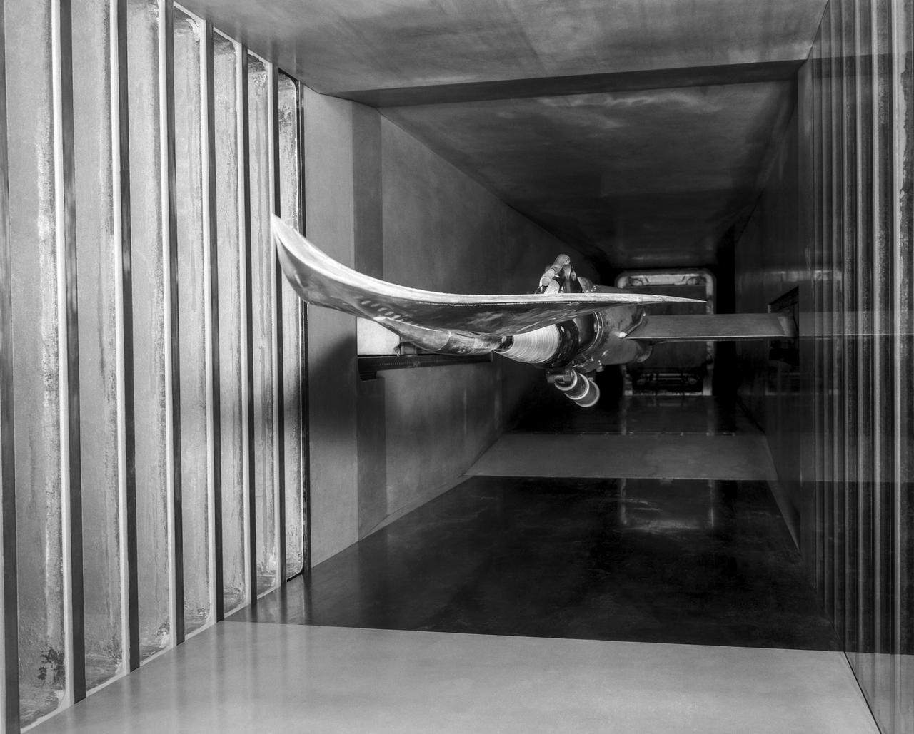
A one-twentieth scale model of the X-15 originally suspended beneath the wing of a B-52 is observed by a scientist of the National Aeronautics and Space Administration (NASA) as it leaves the bomber model in tests to determine the release characteristics and drop motion of the research airplane. Caption: The aerodynamics of air launching the North American X-15 being investigated in the 300MPH Low Speed 7x10 Tunnel, about 1957. Photograph published in Engineer in Charge: A History of the Langley Aeronautical Laboratory, 1917-1958 by James R. Hansen. Page 366. Photograph also published in Sixty Years of Aeronautical Research 1917-1977 By David A. Anderton. A NASA publication. Page 49.
Portrait of Mary Jackson. 2017 Hall of Honor inductee. Langley Research Center NACA and NASA Hall of Honor. In honor and recognition of the ambition and motivation that enabled her career progression from human computer to NASA' s first African-American female engineer, and subsequent career supporting the hiring and promotion of other deserving female and minority employees.
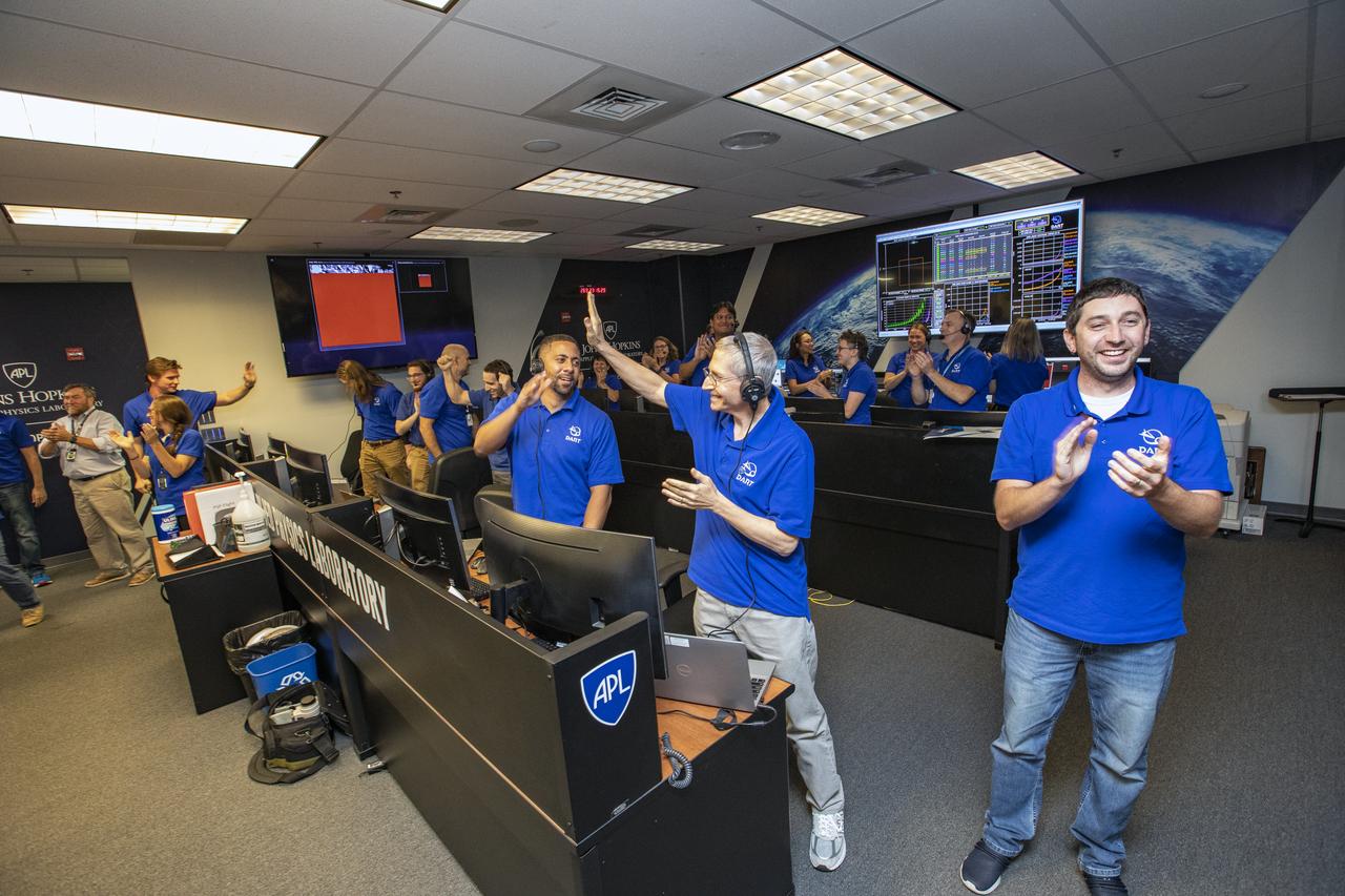
NASA’s Double Asteroid Redirection Test (DART) command team at Johns Hopkins University, Applied Physics Laboratory monitoring the DART spacecraft’s impact into the asteroid Dimorphos. The operation is the first of its kind test to redirect deadly asteroids from hitting Earth.
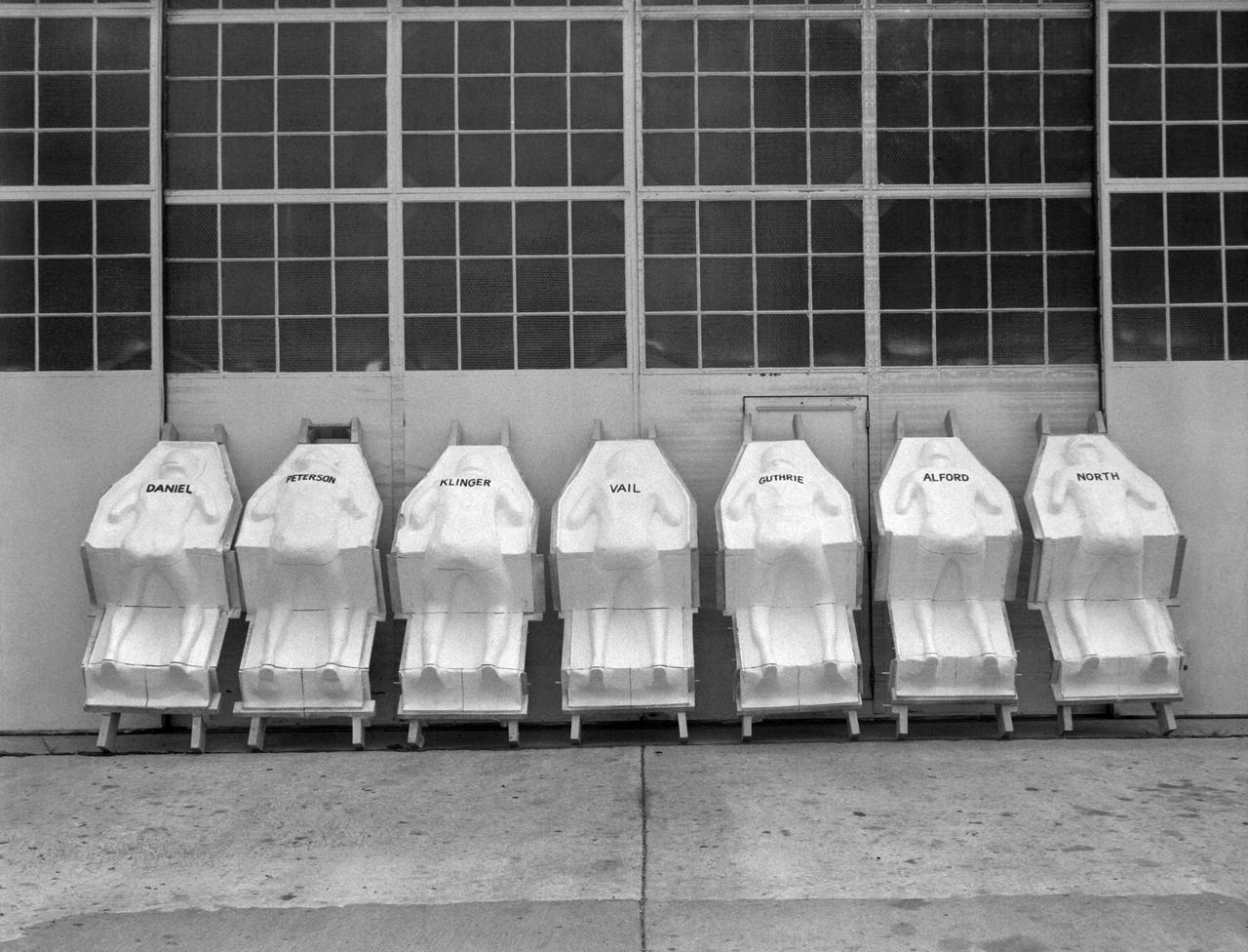
Molds for couches for test pilots, line the NASA Langley Research Centers model shop wall. The names of the test subjects (Langley employees) are written on the back. The couches are similar to those made for each astronaut and fitted into the Mercury capsules for manned spaceflight.
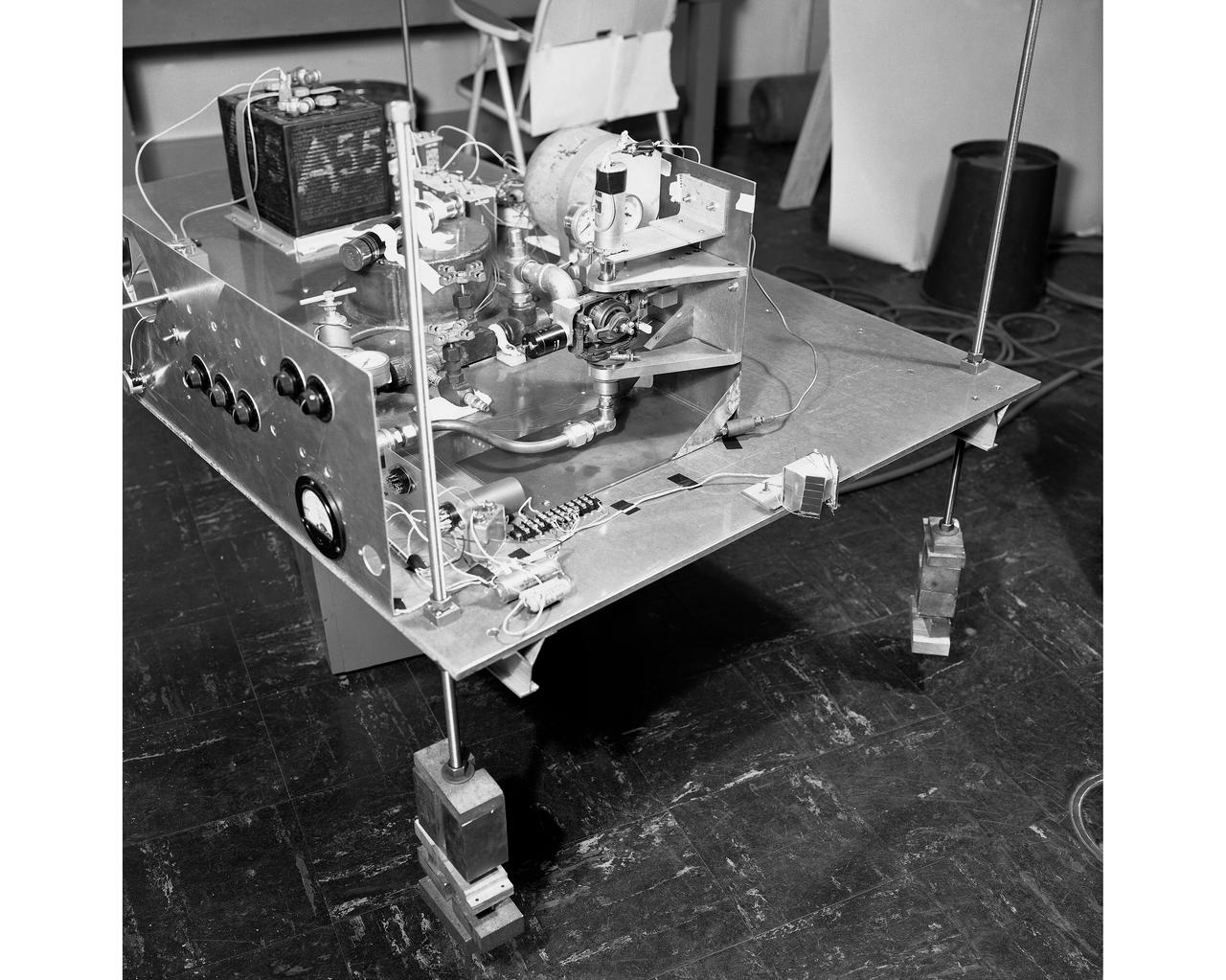
Air Bearings and Stable Platform
NASA’s Double Asteroid Redirection Test (DART) command team at Johns Hopkins University, Applied Physics Laboratory monitoring the DART spacecraft’s impact into the asteroid Dimorphos. The operation is the first of its kind test to redirect deadly asteroids from hitting Earth.
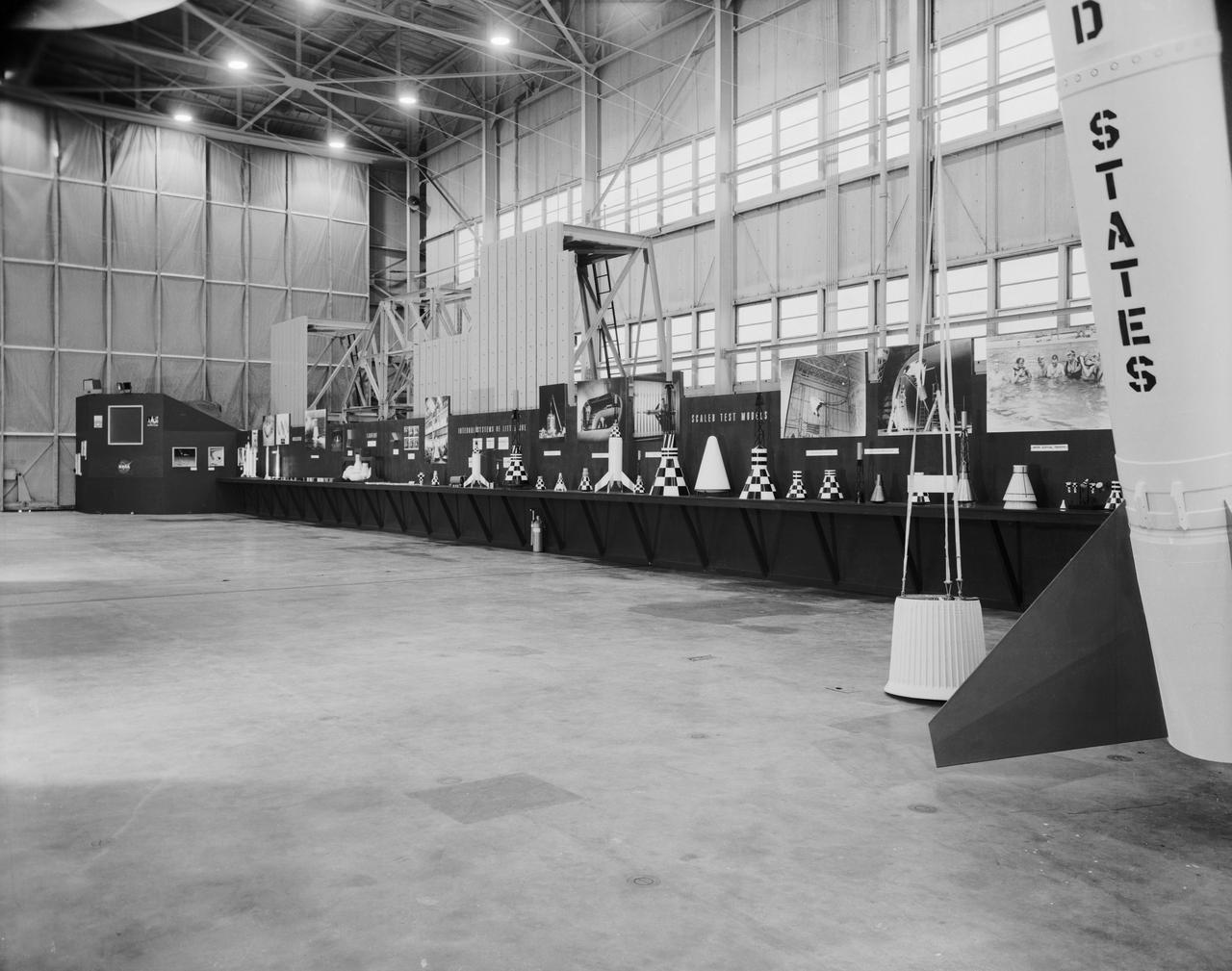
Images take for NASA Document L-1220
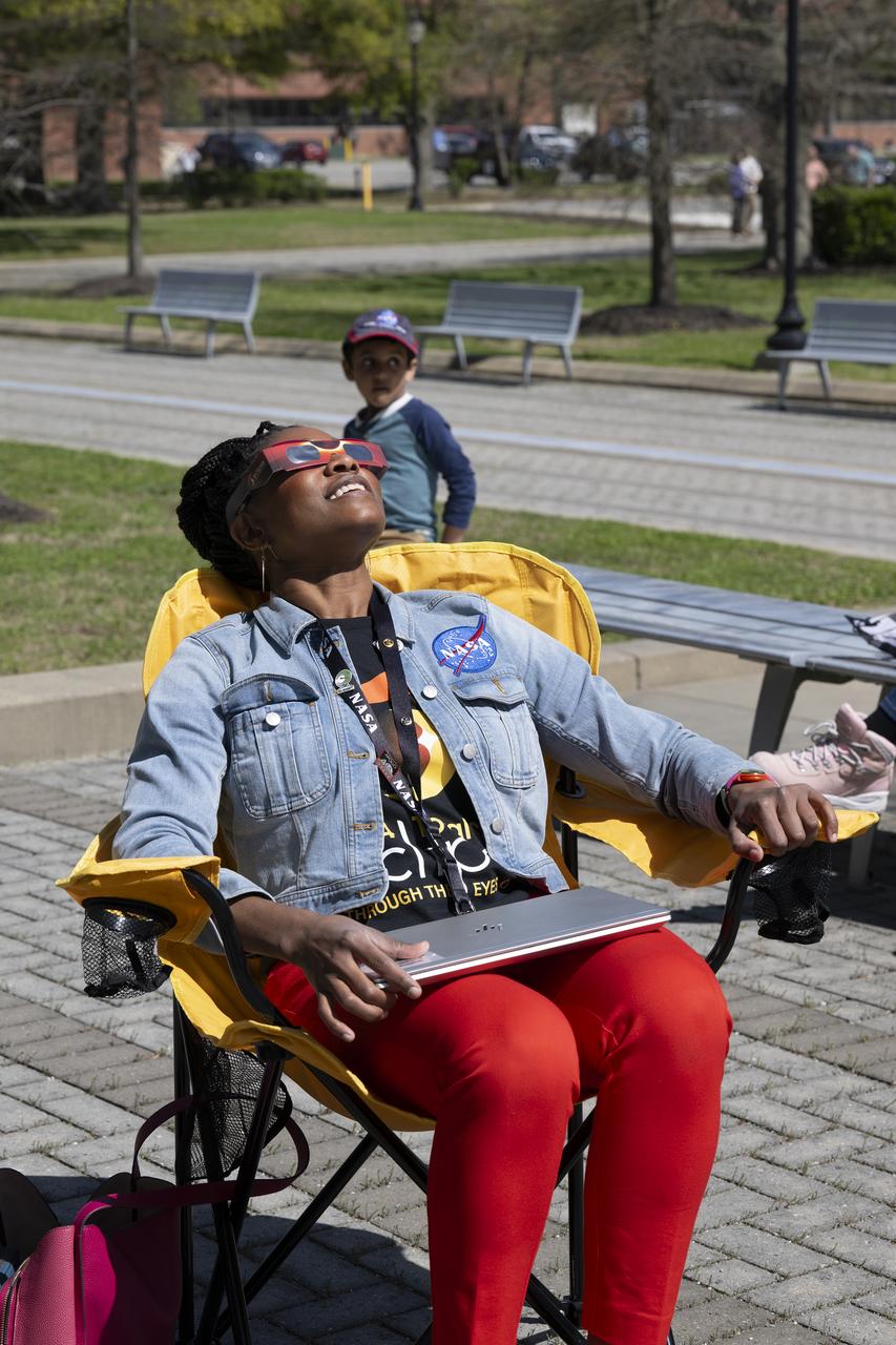
People are seen viewing the partial solar eclipse from NASA Langley Research Center in Hampton, VA, Monday, April 8, 2024. A total solar eclipse swept across a narrow portion of the North American continent from Mexico’s Pacific coast to the Atlantic coast of Newfoundland, Canada. A partial solar eclipse was visible across the entire North American continent along with parts of Central America and Europe. Photo Credit: (NASA/Ryan Hill)
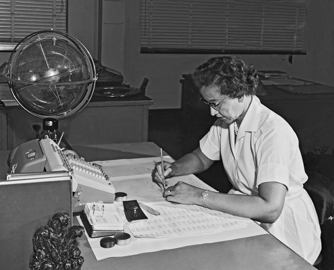
Katherine G. Johnson at Work
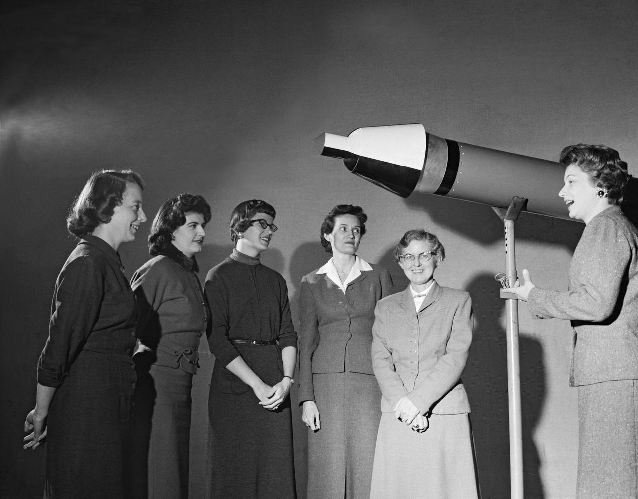
Women Scientists: Lucille Coltrane, Jean Clark Keating, Katherine Cullie Speegle, Doris "Dot" Lee, Ruth Whitman, and Emily Stephens Mueller,Lucille Coltrane is at the far left. She was a computer and worked for Norm Crabill who provided positive identification. Lucille authored a NACA Research Memorandum, Investigation of Two Bluff Shapes in Axial Free Flight Over a Mach Number Range From 0.35 to 2.15 in 1958. Next to Lucille is Jean Clark Keating. Jean was identified by Mary Woerner who said that both Jean and her husband Jerry are now deceased. The third woman from the left is Katherine Cullie Speegle. Katherine co-authored two research papers: Preliminary Results From a Free-Flight Investigation of Boundary-Layer Transition and Heat Transfer on a Highly Polished 8-Inch-Diameter Hemisphere-Cylinder at Mach Numbers up to 3 and Reynolds Numbers Based on a Length of 1 Foot up to 17.7 x 10 to the 6th and Heat Transfer For Mach Numbers Up to 2.2 and Pressure Distributions for Mach Numbers Up to 4.7 From Flight Investigations of a Flat-Face Cone and a Hemisphere-Cone. Norm remembered the woman standing as Doris. Mary Alice identified her as Doris 'Dot' Lee, who worked with Katherine Speegle. Dot was married to a NASA engineer named John Lee. Next to Doris is Ruth Whitman. Norm remembered she and her husband owned a Howard DGA 15 at the airport in WEst Point. That prompted Mary Alice to remember her name and that her husband was Jim. The woman seated on the right is Emily Stephens Mueller. Norm remembers that Emily went to Houston as part of the Space Task Group, but retired back here on the peninsula. In 2008, Emily attended the NACA Reunion X11. She walked over to a table of books about the history of NACA, former NACA facilities and the organization's aviation pioneers and saw a book about women of flight from the Dryden Research Center and paused, then pointed somewhat in amazement. "ThatÕs me," she said of a picture on the cover of her on the far left of a line of women. She was at Dryden from 1948-49.
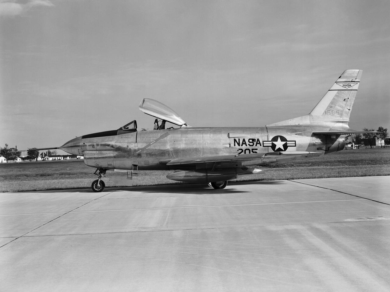
F-86 D NASA 205
Lunar Landing Research Facility. Gantry facility 1297
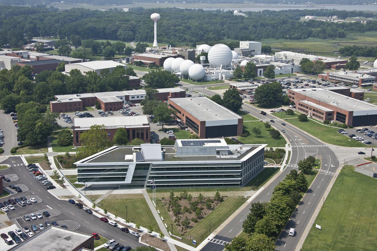
Aerial of NASA Langley Research Center with headquarter building in the fore ground
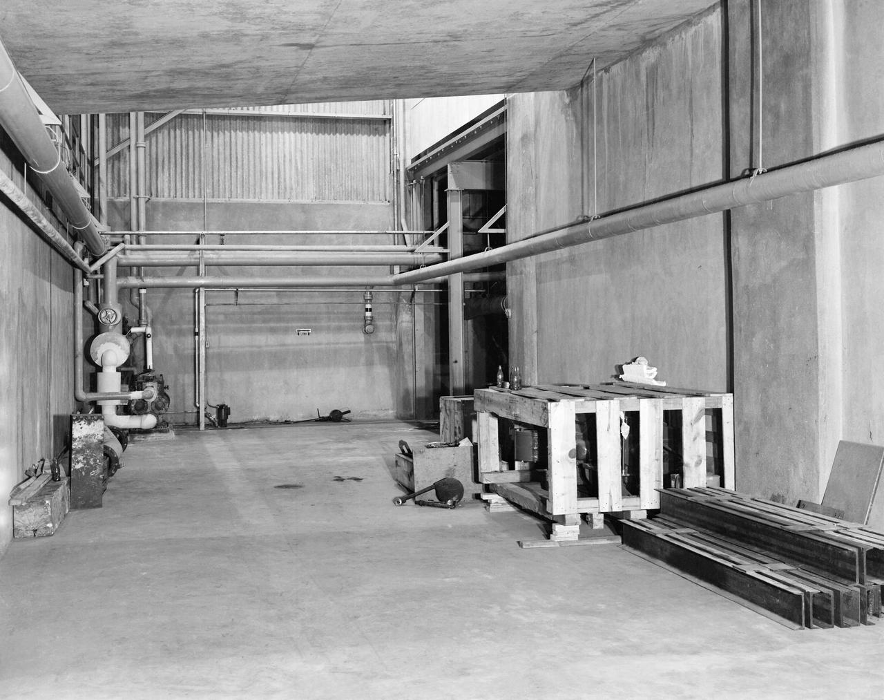
Local for Hypersonic Continuous Flow Facility
A 1/10th Scale Model of the X-15 research plane is prepared in Langley's 7 x 10 Foot Wind Tunnel for studies relating to spin characteristics. -- Photograph published in Winds of Change, 75th Anniversary NASA publication (page 66), by James Schultz.
Lunar Landing Simulator: Astronaut Roger B. Chaffee (left) receives instruction from Maxwell W. Goode, a scientist at NASA s Langley Research Center. Goode is explaining the operation of the Lunar Landing Simulator at the Lunar Landing Research Facility. Chaffee was one of the third group of astronauts selected by NASA in October 1963. In addition to participating in the overall training program, he was also tasked with working on flight control communications systems, instrumentation systems, and attitude and translation control systems in the Apollo Branch of the Astronaut office. On March 21, 1966, he was selected as one of the pilots for the AS-204 mission, the first 3-man Apollo flight. Lieutenant Commander Chaffee died on January 27, 1967, in the Apollo spacecraft flash fire during a launch pad test at Kennedy Space Center, Florida.
NASA’s Double Asteroid Redirection Test (DART) command team at Johns Hopkins University, Applied Physics Laboratory monitoring the DART spacecraft’s impact into the asteroid Dimorphos. The operation is the first of its kind test to redirect deadly asteroids from hitting Earth.
Astronauts Stuart A. Roosa, and Alfred M. Worden training a tRendezvous Docking Simulator NASA Langley. Worden was one of the 19 astronauts selected by NASA in April 1966. He served as a member of the astronaut support crew for the Apollo 9 flight and as backup command module pilot for the Apollo 12 flight. Colonel Roosa was one of the 19 astronauts selected by NASA in April 1966. He was a member of the astronaut support crew for the Apollo 9 flight.

B-33 Vega Turrets. Photo are listed in the NACA Wartime report L-463, October 1942, Test of a Large Spherical Turret and a modified Turret on a Typical Bomber Fuselage by Axel T. Mattson.
Astronaut Eugene Cernan at Lunar Lander Research Facility. Cernan under gantry, in training module. Captain Cernan was one of fourteen astronauts selected by NASA in October 1963. On his second space flight, he was lunar module pilot of Apollo 10, May 18-26, 1969, the first comprehensive lunar-orbital qualification and verification flight test of an Apollo lunar module.
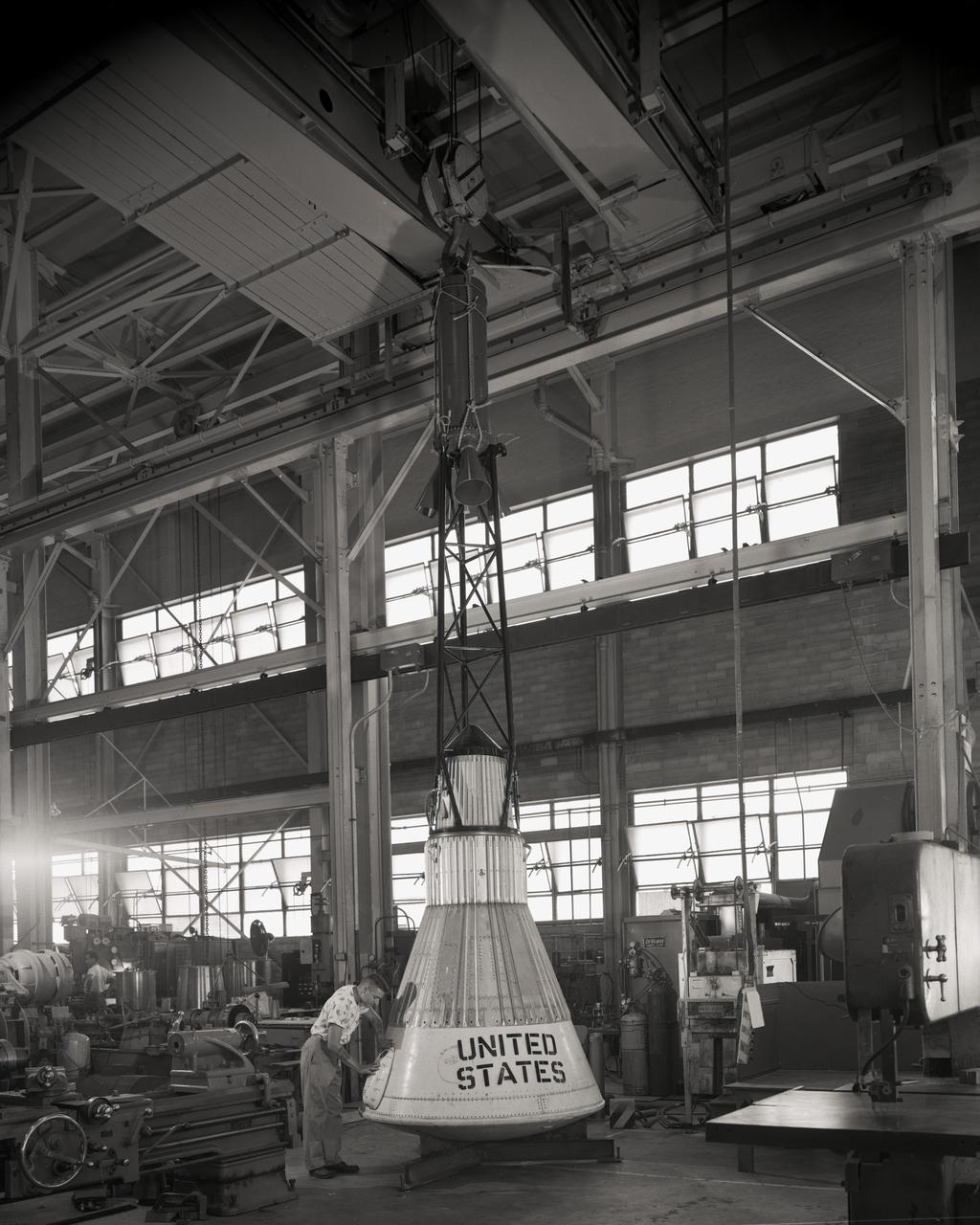
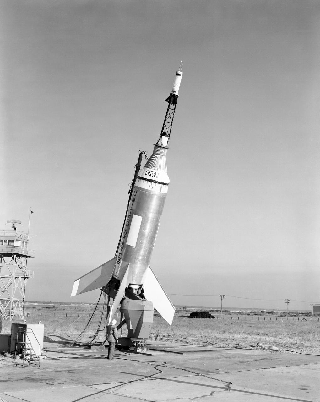
Mock-up of the Mercury capsule on display at the first NASA inspection held on October 24, 1959.
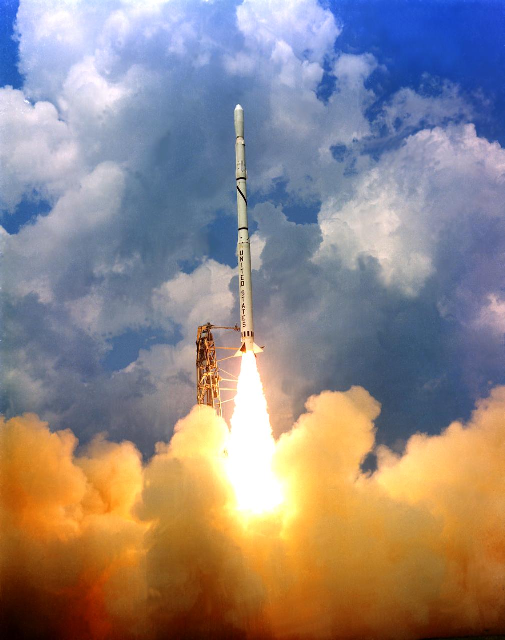
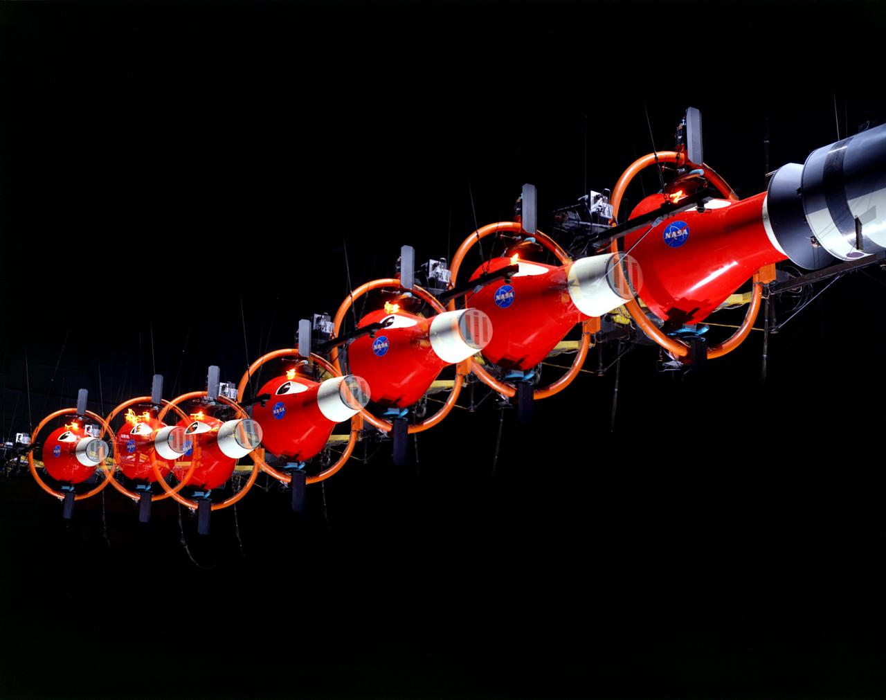
Scout launch vehicle lift off on Wallops Island in 1965. The Scout launch vehicle was used for unmanned small satellite missions, high altitude probes, and reentry experiments. Scout, the smallest of the basic launch vehicles, is the only United States launch vehicle fueled exclusively with solid propellants. Published in the book " A Century at Langley" by Joseph Chambers pg. 92
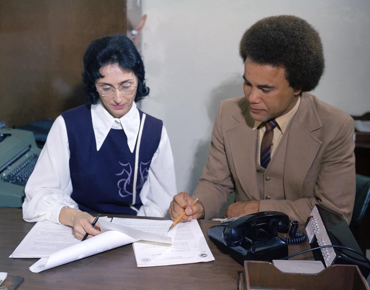
Minority Professionals at NASA Langley Research Center Samuel J. Scott on the right.
The Little Joe launch vehicle being readied for a test launch from Wallops in January 1960... Page 77. Photograph published in Winds of Change, 75th Anniversary NASA publication, by James Schultz. **note - see L59-5137 page 77 also. Photograph published in Engineer in Charge: A History of the Langley Aeronautical Laboratory, 1917-1958 by James R. Hansen. Page 389. ...was conceived by Langley engineers Max Faget and Paul Purser even before STG (Space Task Group) was organized.
HSC Model 154 Dyna Soar (Martin-Bell)
NASA’s Double Asteroid Redirection Test (DART) command team at Johns Hopkins University, Applied Physics Laboratory monitoring the DART spacecraft’s impact into the asteroid Dimorphos. The operation is the first of its kind test to redirect deadly asteroids from hitting Earth.
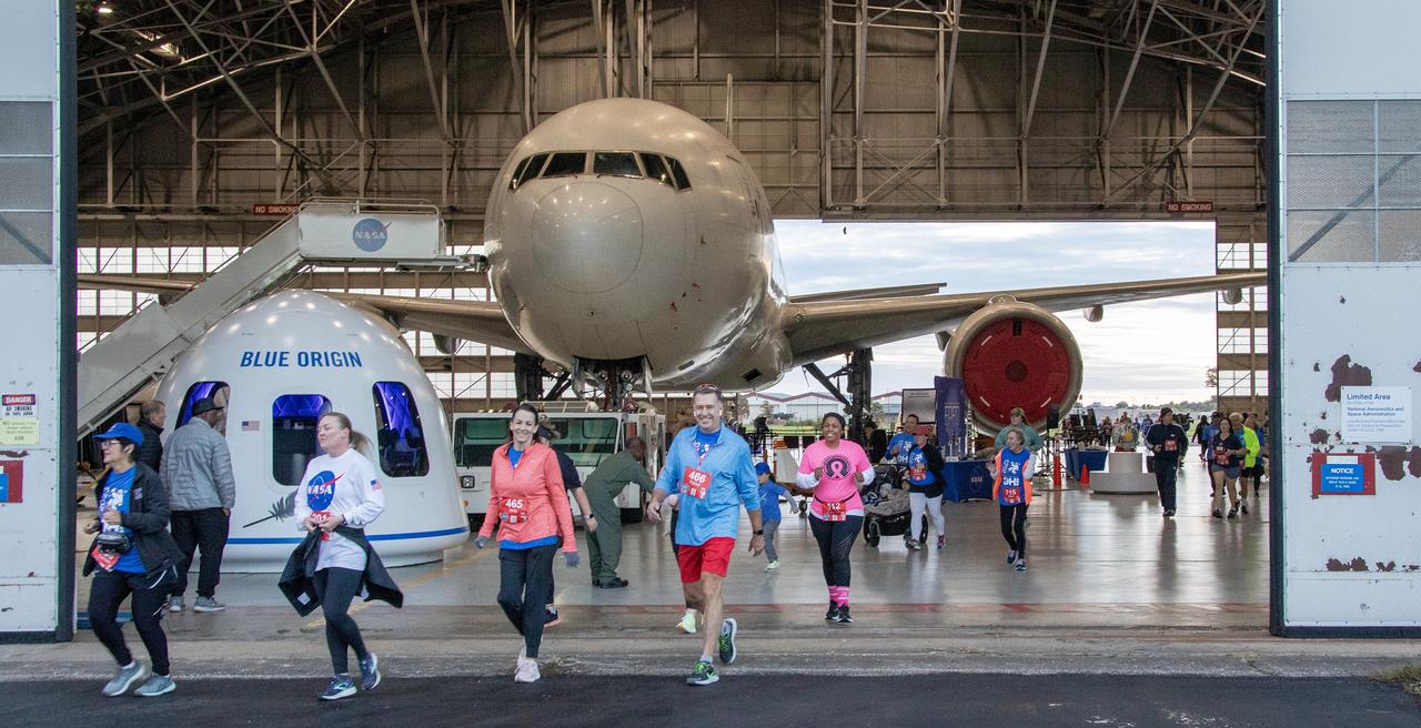
More than 37,000 people registered to attend the NASA Langley open house. Starting with the Annual 5K Moon Walk Run and the talented Nils Larson, X59 pilot and Astronaut Victor Glover reunited at Langley’s hangar and hosted by Center Director Clayton Turner.
Martin-Bell Dyna Soar I in Unitary Tunnel
Astronauts Stuart A. Roosa, and Alfred M. Worden training a tRendezvous Docking Simulator NASA Langley. Worden was one of the 19 astronauts selected by NASA in April 1966. He served as a member of the astronaut support crew for the Apollo 9 flight and as backup command module pilot for the Apollo 12 flight. Colonel Roosa was one of the 19 astronauts selected by NASA in April 1966. He was a member of the astronaut support crew for the Apollo 9 flight.

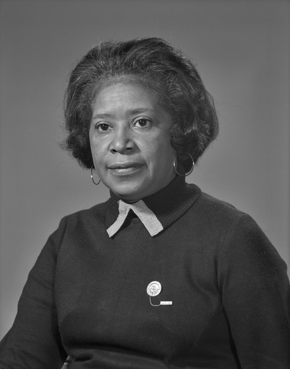
Portrait of Christine M. Darden
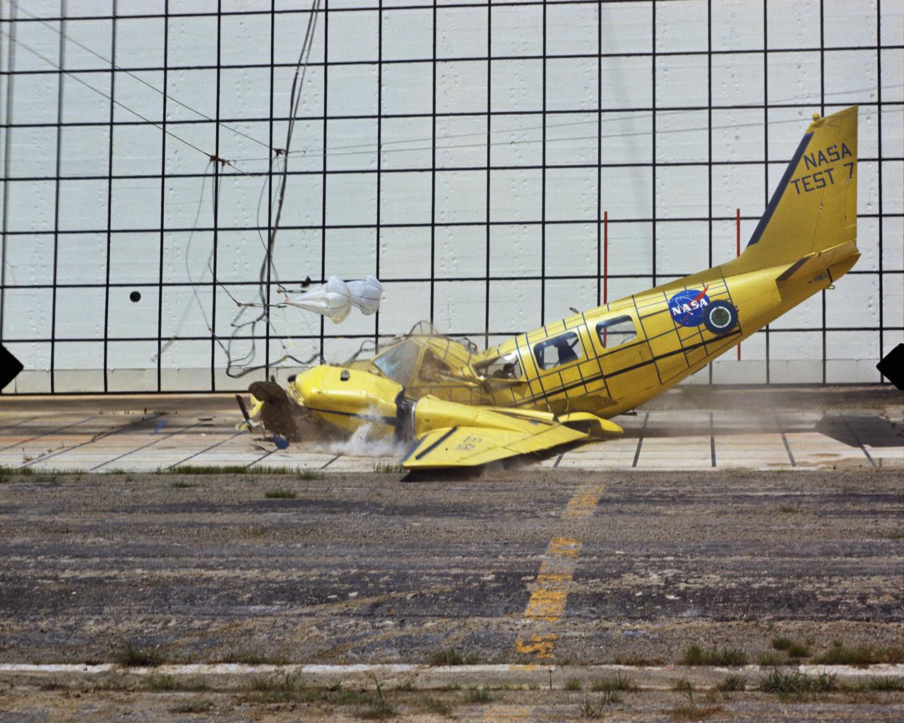
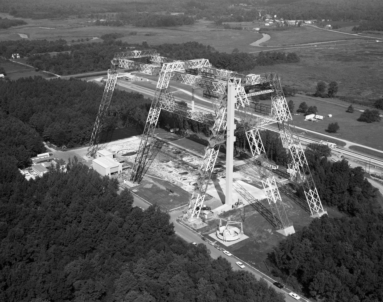
Photographed on: 08/03/75. -- By 1972 the Lunar Landing Research Facility was no longer in use for its original purpose. The 400-foot high structure was swiftly modified to allow engineers to study the dynamics of aircraft crashes. "The Impact Dynamics Research Facility is used to conduct crash testing of full-scale aircraft under controlled conditions. The aircraft are swung by cables from an A-frame structure that is approximately 400 ft. long and 230 foot high. The impact runway can be modified to simulate other grand crash environments, such as packed dirt, to meet a specific test requirement." "In 1972, NASA and the FAA embarked on a cooperative effort to develop technology for improved crashworthiness and passenger survivability in general aviation aircraft with little or no increase in weight and acceptable cost. Since then, NASA has "crashed" dozens of GA aircraft by using the lunar excursion module (LEM) facility originally built for the Apollo program." This photograph shows Crash Test No. 7. Crash Test: Test #7
NASA’s Double Asteroid Redirection Test (DART) command team at Johns Hopkins University, Applied Physics Laboratory monitoring the DART spacecraft’s impact into the asteroid Dimorphos. The operation is the first of its kind test to redirect deadly asteroids from hitting Earth.
POGO is a device that uses cables connected to the ceiling to suspend an astronaut. POGO supports five-sixths of a person's weight; it mimics the one-sixth gravity of the moon. An astronaut walking around on POGO has the sensation of walking on the moon. POGO has been around since the Apollo days - in fact, the device gets its name from the way Apollo astronauts tended to bounce when suspended from it. The real name for POGO is the Partial Gravity Simulator.
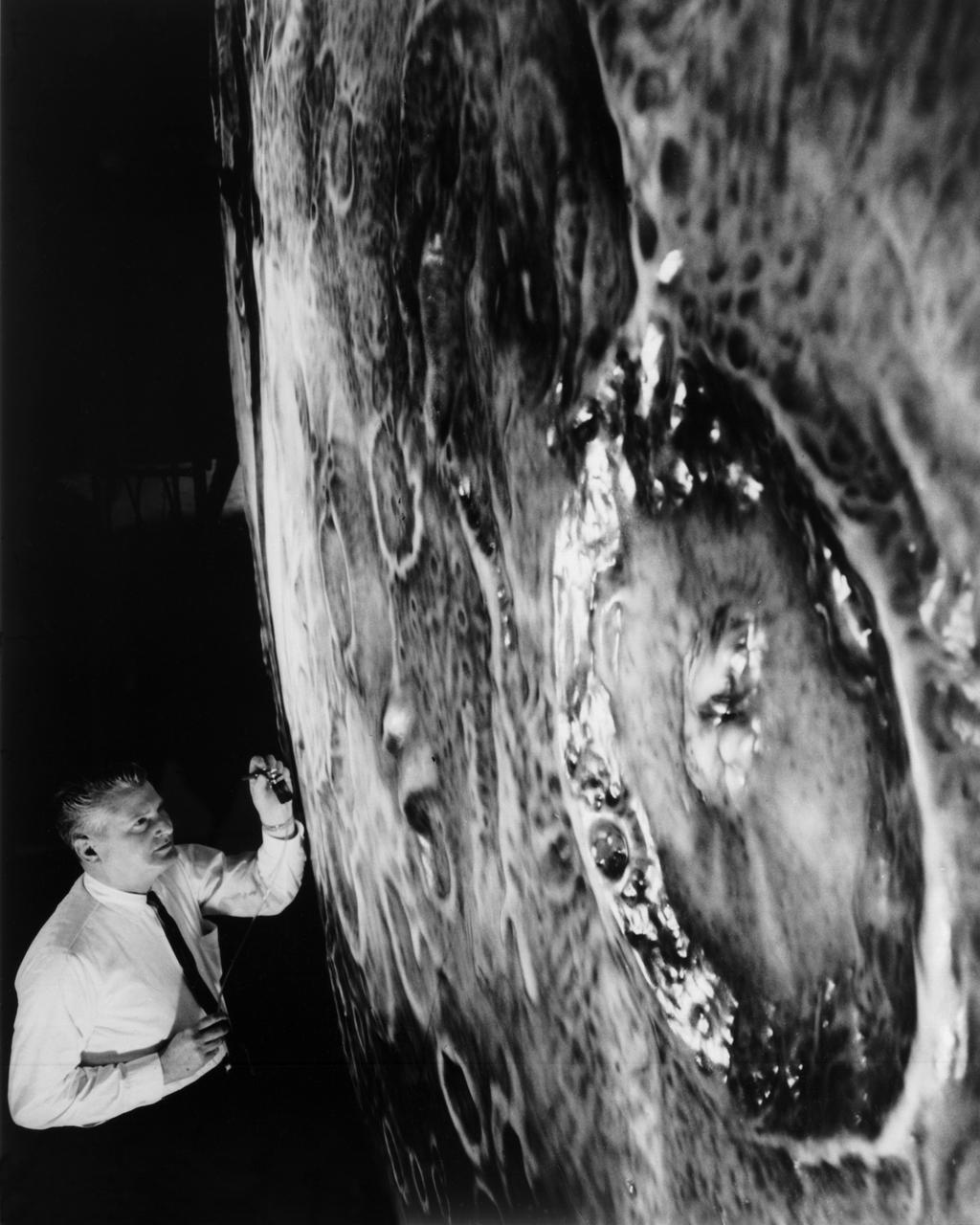
Artists used paintbrushes and airbrushes to recreate the lunar surface on each of the four models comprising the LOLA simulator. Project LOLA or Lunar Orbit and Landing Approach was a simulator built at Langley to study problems related to landing on the lunar surface. It was a complex project that cost nearly $2 million dollars. James Hansen wrote: "This simulator was designed to provide a pilot with a detailed visual encounter with the lunar surface; the machine consisted primarily of a cockpit, a closed-circuit TV system, and four large murals or scale models representing portions of the lunar surface as seen from various altitudes. The pilot in the cockpit moved along a track past these murals which would accustom him to the visual cues for controlling a spacecraft in the vicinity of the moon. Unfortunately, such a simulation--although great fun and quite aesthetic--was not helpful because flight in lunar orbit posed no special problems other than the rendezvous with the LEM, which the device did not simulate. Not long after the end of Apollo, the expensive machine was dismantled." (p. 379) Ellis J. White further described LOLA in his paper "Discussion of Three Typical Langley Research Center Simulation Programs," "Model 1 is a 20-foot-diameter sphere mounted on a rotating base and is scaled 1 in. = 9 miles. Models 2,3, and 4 are approximately 15x40 feet scaled sections of model 1. Model 4 is a scaled-up section of the Crater Alphonsus and the scale is 1 in. = 200 feet. All models are in full relief except the sphere." -- Published in James R. Hansen, Spaceflight Revolution: NASA Langley Research Center From Sputnik to Apollo, (Washington: NASA, 1995), p. 379; From Ellis J. White, "Discussion of Three Typical Langley Research Center Simulation Programs," Paper presented at the Eastern Simulation Council (EAI's Princeton Computation Center), Princeton, NJ, October 20, 1966.
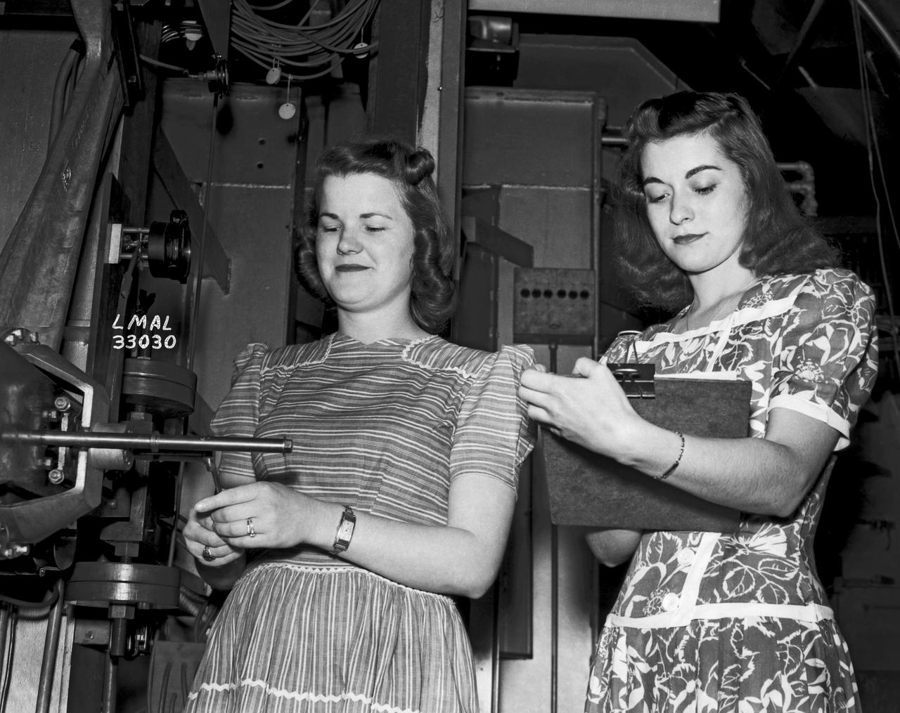
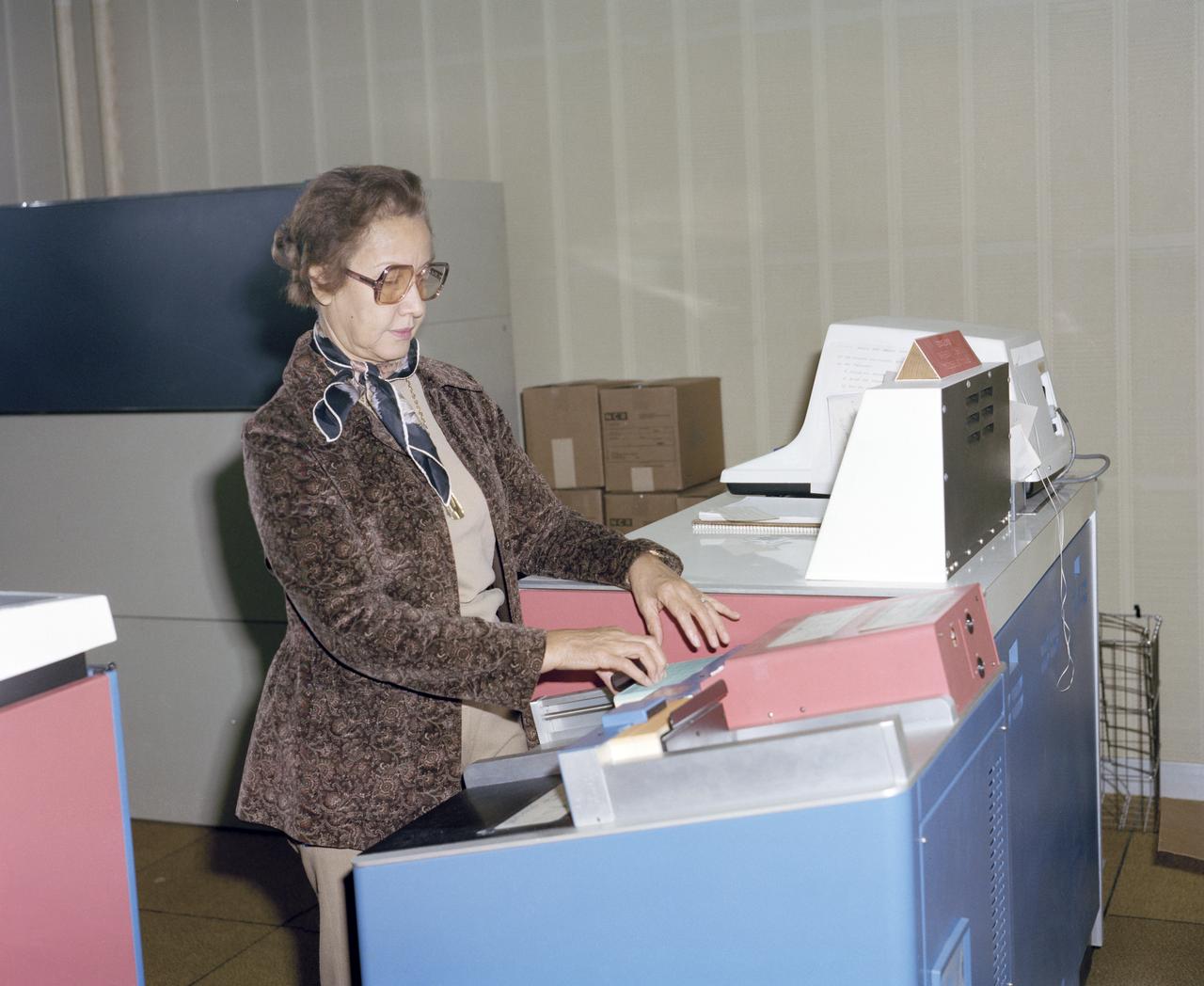
Women Adequately Filling Posts in NACA Laboratory: Nearly 200 women are employed at the Langley Laboratory of the National Advisory Committee for Aeronautics in a limited capacity as mechanics’ helpers and minor laboratory aids on the jobs formerly handled by men, according to E.H. Derring, of the Aerodynamics Division. Many phases of the operations of various wind tunnels at the laboratory are now handled by women with experienced male supervision. Mr. Derring said, pointing out that the reading of the data indicated on wind tunnel instruments during a test is done in a large measure by women. In addition to reading the instruments and computing and integrating engineering test data obtained from tunnel investigations, the minor laboratory aides assist in the preparation of aircraft models preliminary to testing. Women employees who will serve in the Aerodynamics Division of the Laboratory attend an orientation class for two weeks, during which they receive instruction on phases of the work they will do and their aptitudes for different types of work are evaluated in order that they may be properly placed. More than 100 women are employed in minor laboratory apprentices, performing mechanical work heretofore done by men. These women are employed in the various shops of the laboratory. Women in the woodworking shops are taught to operate 15 different machines in carrying out their assignments. Norfolk new paper article from 1943 by Lee Dickinson.
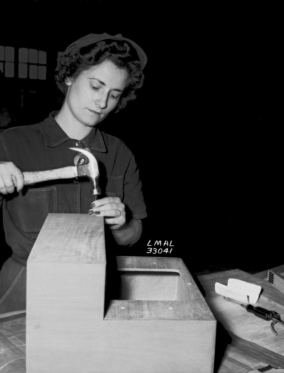
Women Adequately Filling Posts in NACA Laboratory: Nearly 200 women are employed at the Langley Laboratory of the National Advisory Committee for Aeronautics in a limited capacity as mechanics’ helpers and minor laboratory aids on the jobs formerly handled by men, according to E.H. Derring, of the Aerodynamics Division. Many phases of the operations of various wind tunnels at the laboratory are now handled by women with experienced male supervision. Mr. Derring said, pointing out that the reading of the data indicated on wind tunnel instruments during a test is done in a large measure by women. In addition to reading the instruments and computing and integrating engineering test data obtained from tunnel investigations, the minor laboratory aides assist in the preparation of aircraft models preliminary to testing. Women employees who will serve in the Aerodynamics Division of the Laboratory attend an orientation class for two weeks, during which they receive instruction on phases of the work they will do and their aptitudes for different types of work are evaluated in order that they may be properly placed. More than 100 women are employed in minor laboratory apprentices, performing mechanical work heretofore done by men. These women are employed in the various shops of the laboratory. Women in the woodworking shops are taught to operate 15 different machines in carrying out their assignments. Norfolk new paper article from 1943 by Lee Dickinson.
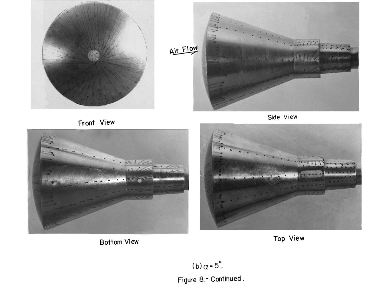
Mach number 6.9 Inlet. These negatives in jackets also: L-1958-2984.1 Figure 3b cone in NASA document L-1643 L-1958-2980.1 Figures 3a in document L-1643 declassified from Confidential
Astronauts Stuart A. Roosa, and Alfred M. Worden training a tRendezvous Docking Simulator NASA Langley. Worden was one of the 19 astronauts selected by NASA in April 1966. He served as a member of the astronaut support crew for the Apollo 9 flight and as backup command module pilot for the Apollo 12 flight. Colonel Roosa was one of the 19 astronauts selected by NASA in April 1966. He was a member of the astronaut support crew for the Apollo 9 flight.
Federal Women's Program with Mary Jackson giving out awards. In 1958 Mary Jackson became NASA's first black female engineer.
Leading Edge Vortex Suppression Series with Christine Darden in photos
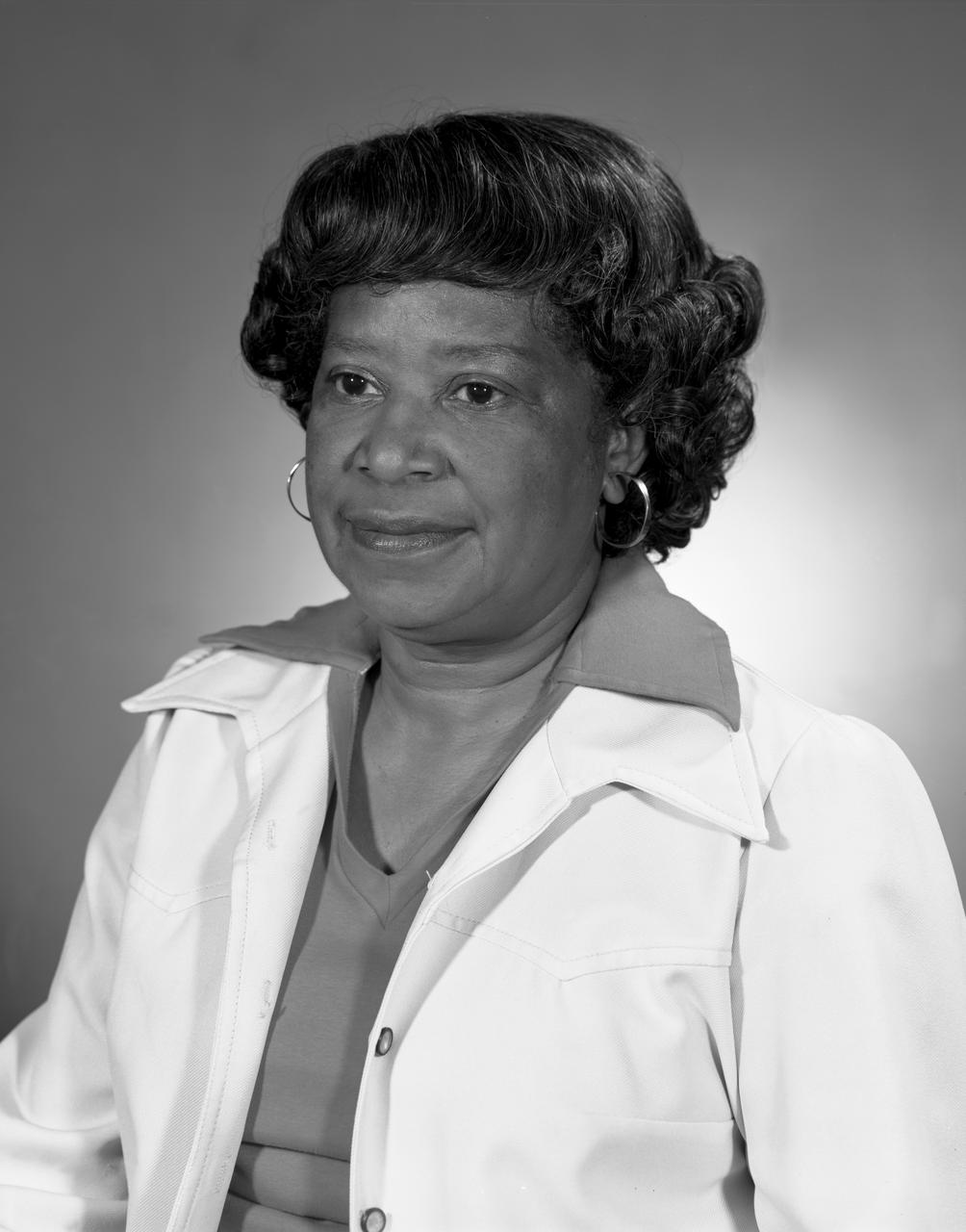
Portrait of Mary Jackson. At the time this photo was taken on October 9, 1971, Mrs. Jackson was working as a Equal Employment Opportunity (EEO) Counselor Mary Jackson, was NASA’s first black female engineer.
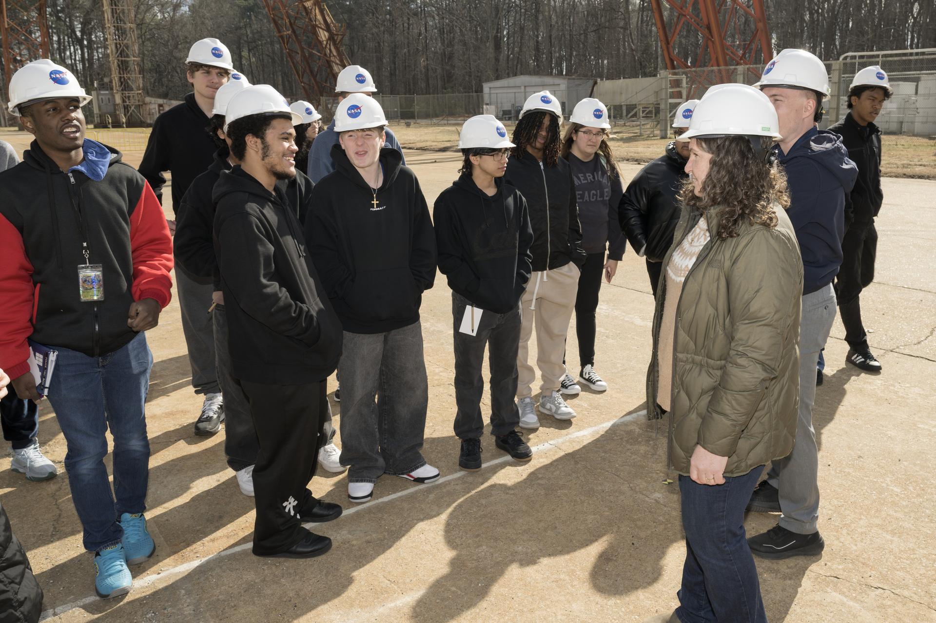
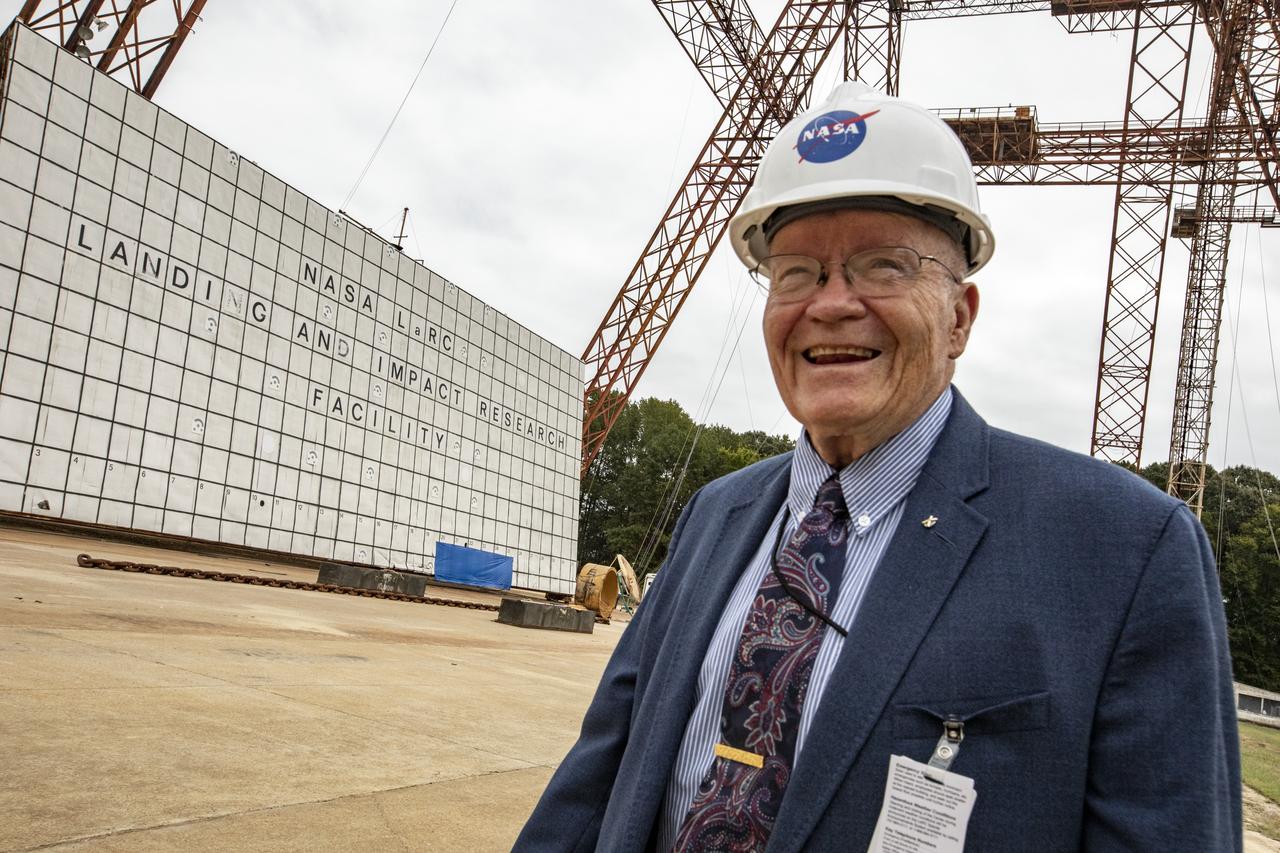
Old Dominion University's (ODU) Maritime Engineering and Environmental Studies Academy (MEESA) lab school juniors, tour the NASA Langley’s Landing and Impact Research Facility (LandIR), also know as the Gantry. The students were task to create an exhibit for the Vestil Aluminum/Steel Crane (VASC) of the crane used to build the Gantry.
Portrait of Dr. William H. Michael, Jr.
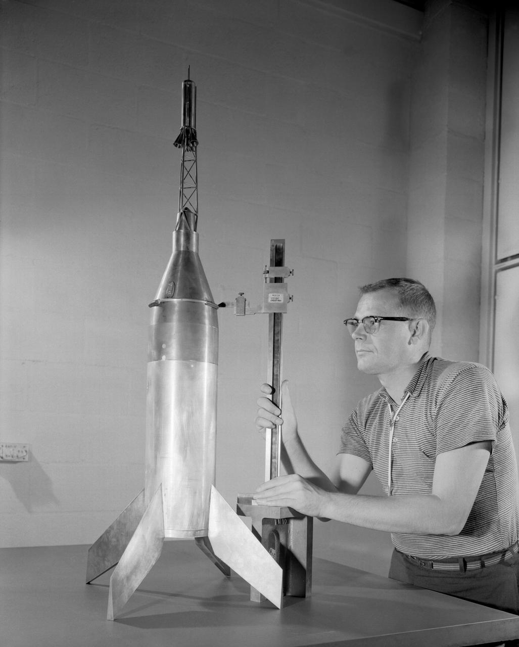
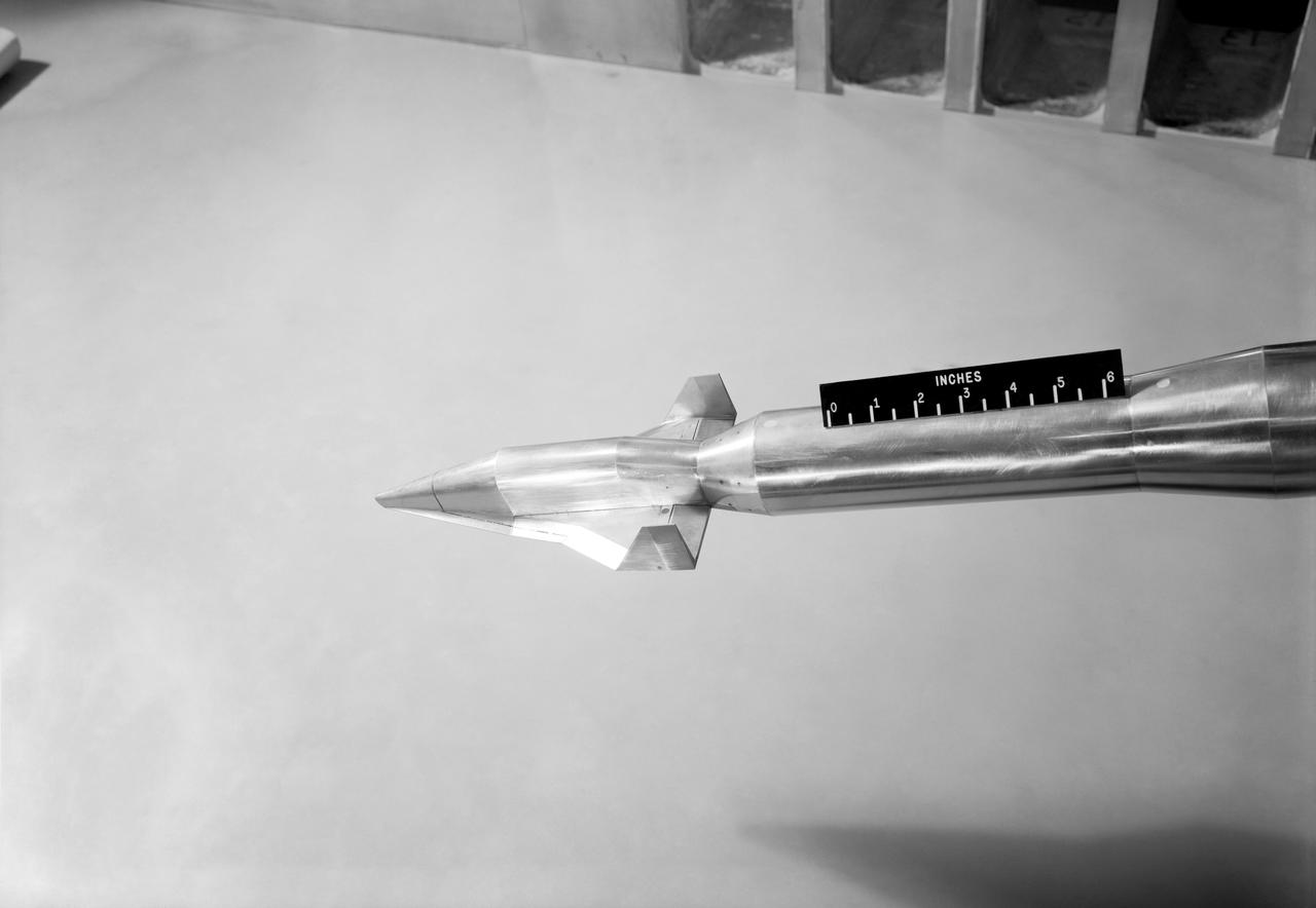
Publicity photograph of a technician measuring a wind tunnel model of the Little Joe test vehicle. Joseph Shortal noted that (vol. 3, p. 29): The largest project at Wallops in support of Mercury was the Little Joe project, designed to qualify the abort-escape system under flight conditions. James Hansen (p. 47) writes: STG engineers Max Faget and Paul Purser, then of Langley's PARD, had conceived Little Joe as a space capsule test vehicle even before the establishment of NASA and the formation of the STG. Girlruth understood the importance of the Little Joe tests: We had to be sure there were no serious performance and operational problems that we had simply not thought of in such a new and radical type of flight vehicle. -- Published in James R. Hansen, Spaceflight Revolution: NASA Langley Research Center From Sputnik to Apollo, (Washington: NASA, 1995), p. 47 Joseph A. Shortal, History of Wallops Station: Origins and Activities Through 1949, (Wallops Island, VA: National Aeronautics and Space Administration, Wallops Station, nd), Comment Edition.
WS-110A "Brown Bomber"
Mrs. Katherine G. Johnson at Work

First test flight testing the visual display for the X59. The XVS display is aboard the B200 and the LC40 will be interacting as part of the test.
Miscellaneous Charts, space capsule
R_1982-L-06131 007
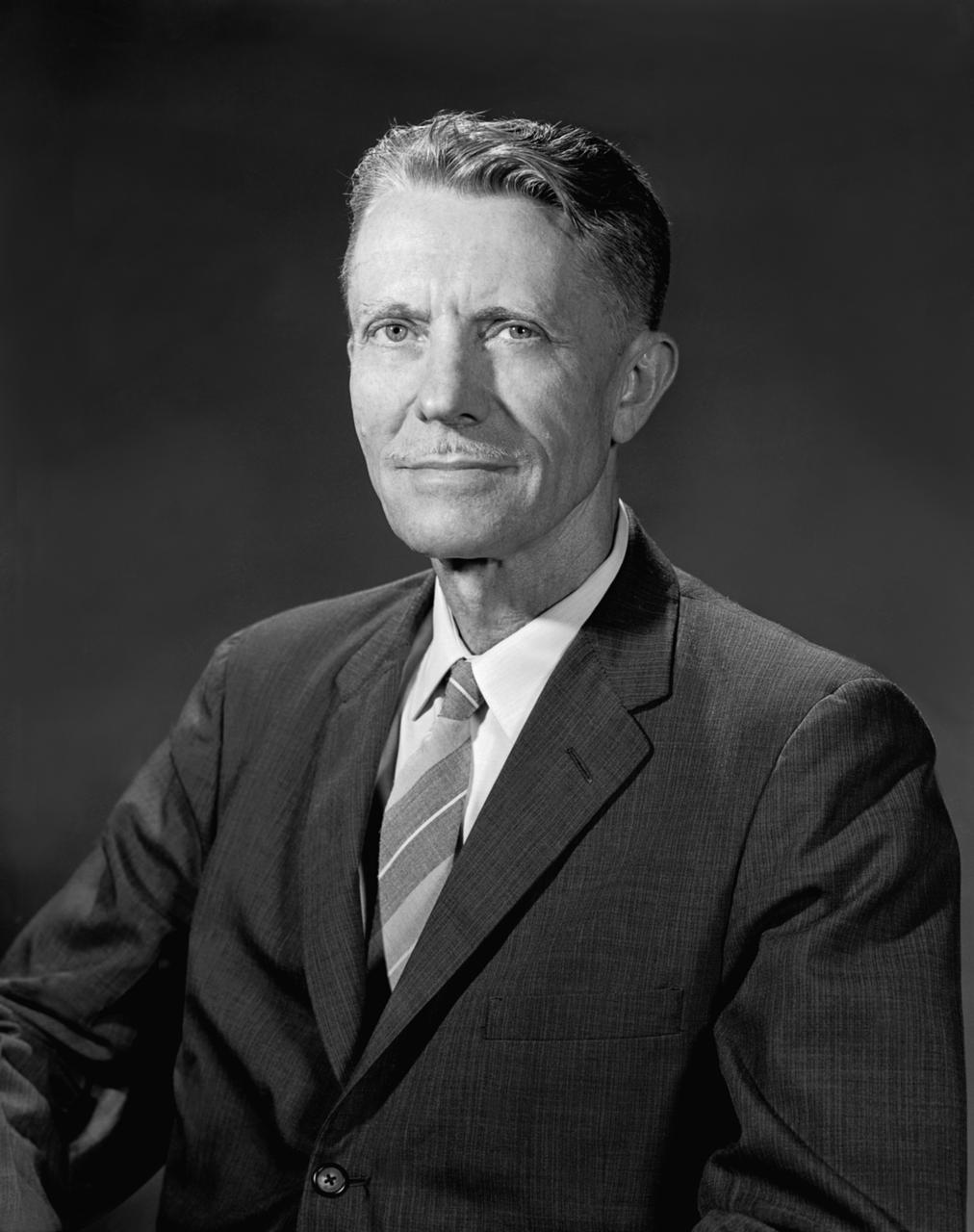
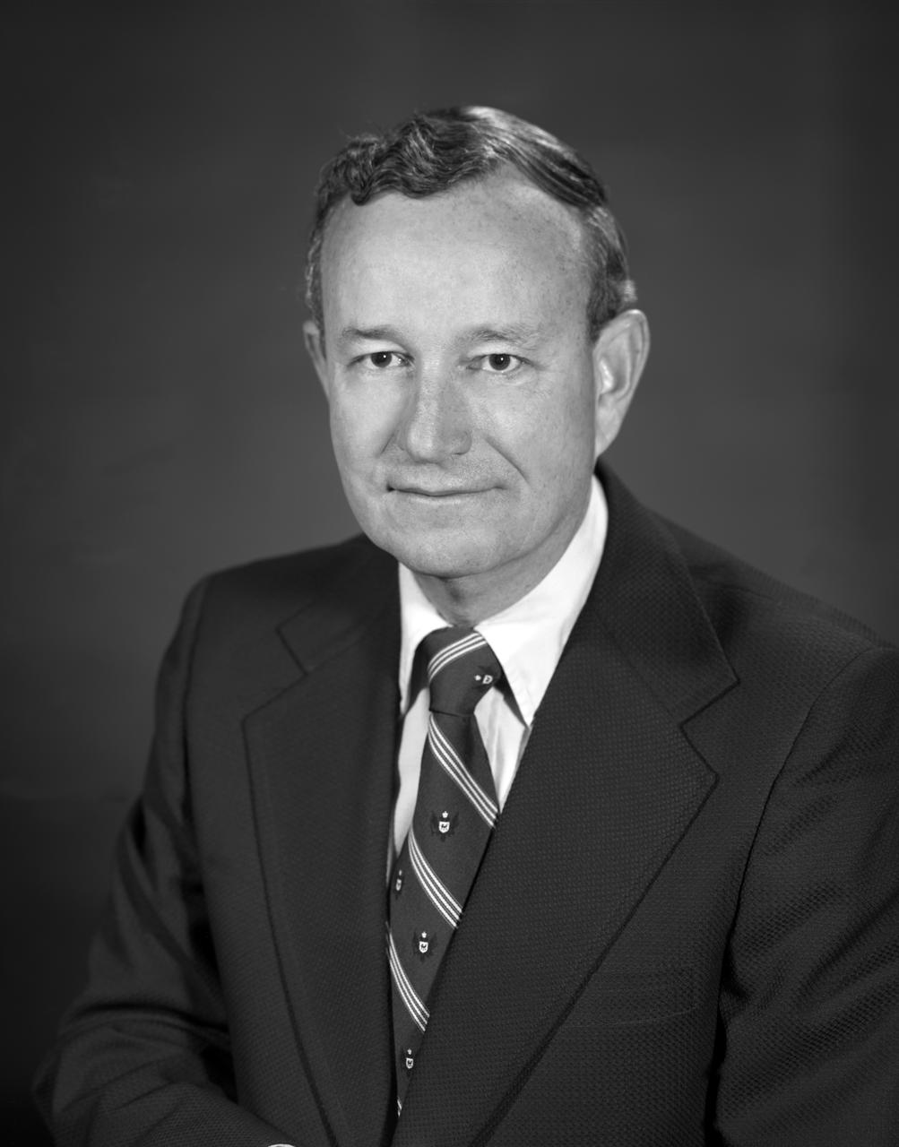
Portrait of Floyd L. Thompson NASA Langley Center Director
Flat Delta Model Flying in Full Scale Tunnel (FST) (Boiseau)
Various Components of Goodyear Inflatable Airplane in Full Scale Tunnel building 643 Test 238
WS-110A Brown Bomber in Unitary Wind Tunnel Low Mach Number Test
Vehicles and Missions Studies Charts, Space Capsule
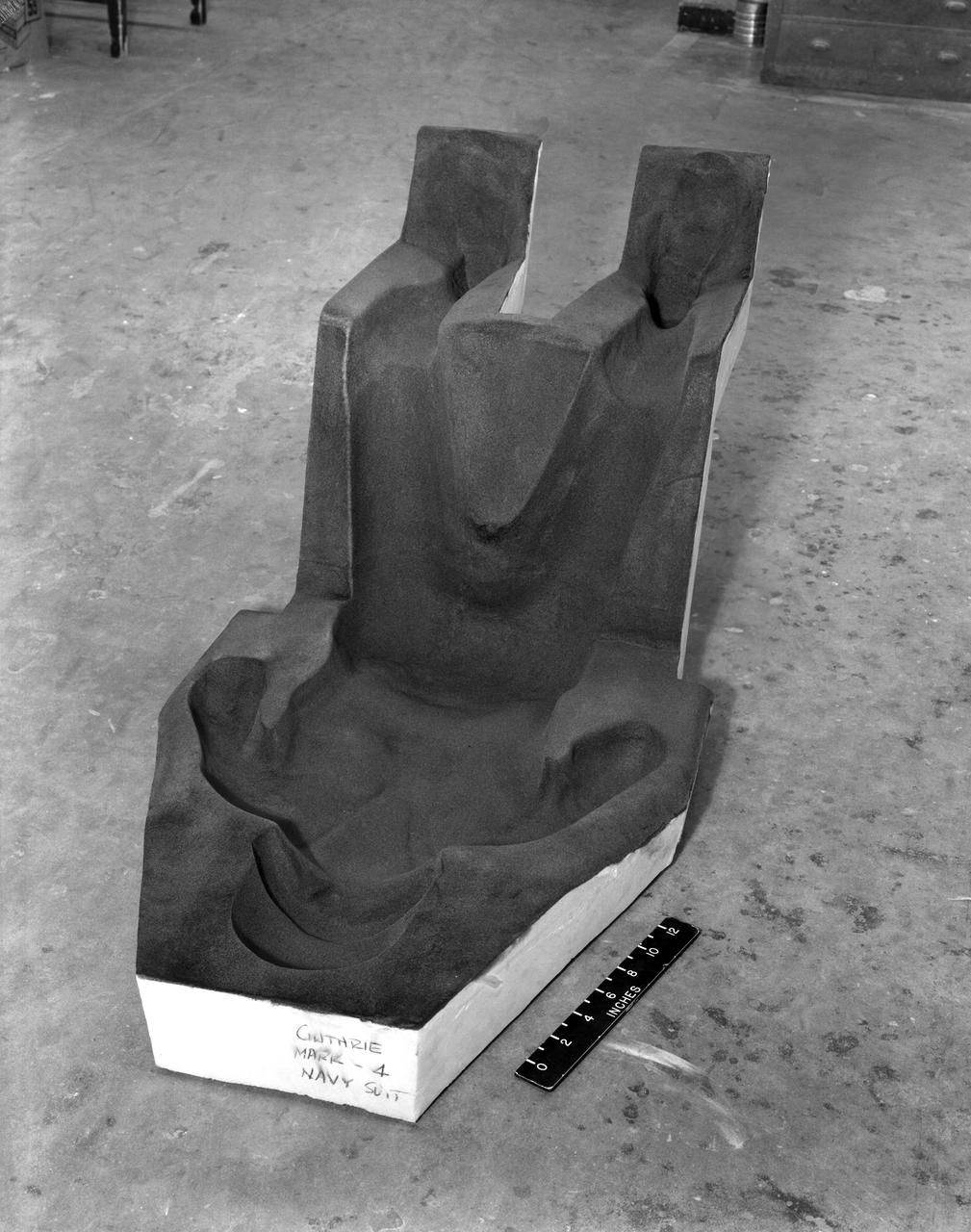
Lockfoam Couch
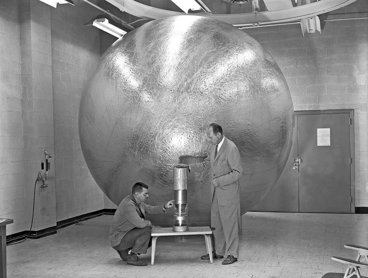
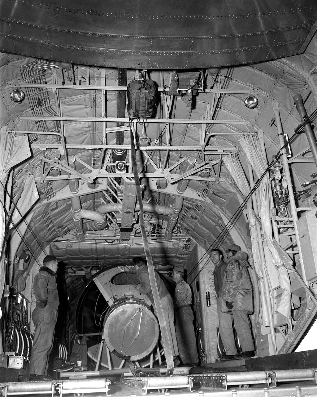
In July 1959, William J. O Sullivan (right standing) and unidentified engineer examine the capsule containing the tightly folded and packed 12 diameter Beacon satellite inside. Taken from NASA SP-4308 Pg. 174
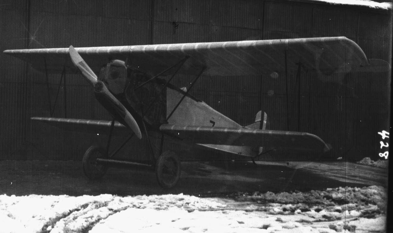
R_1923-L-00427 002
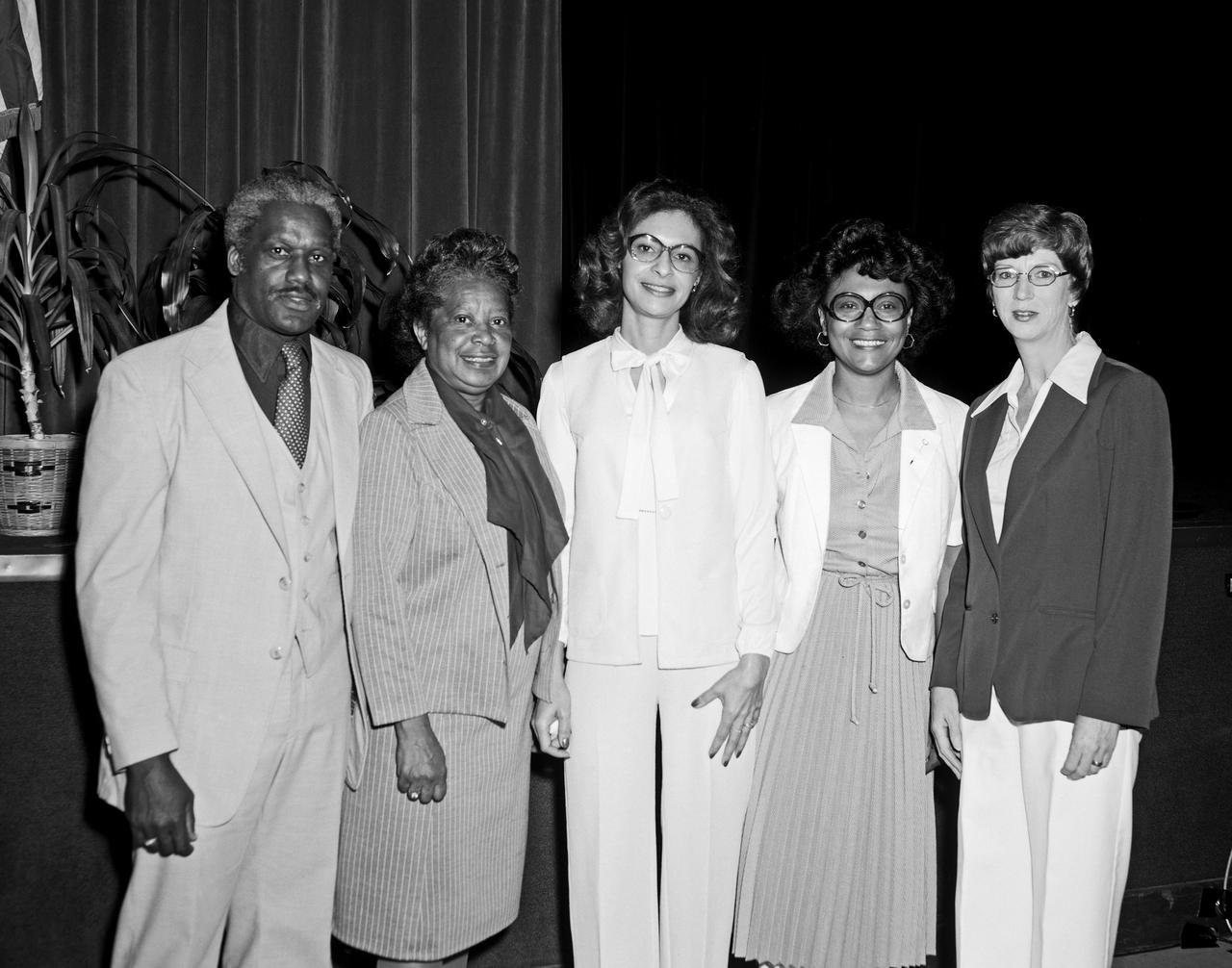
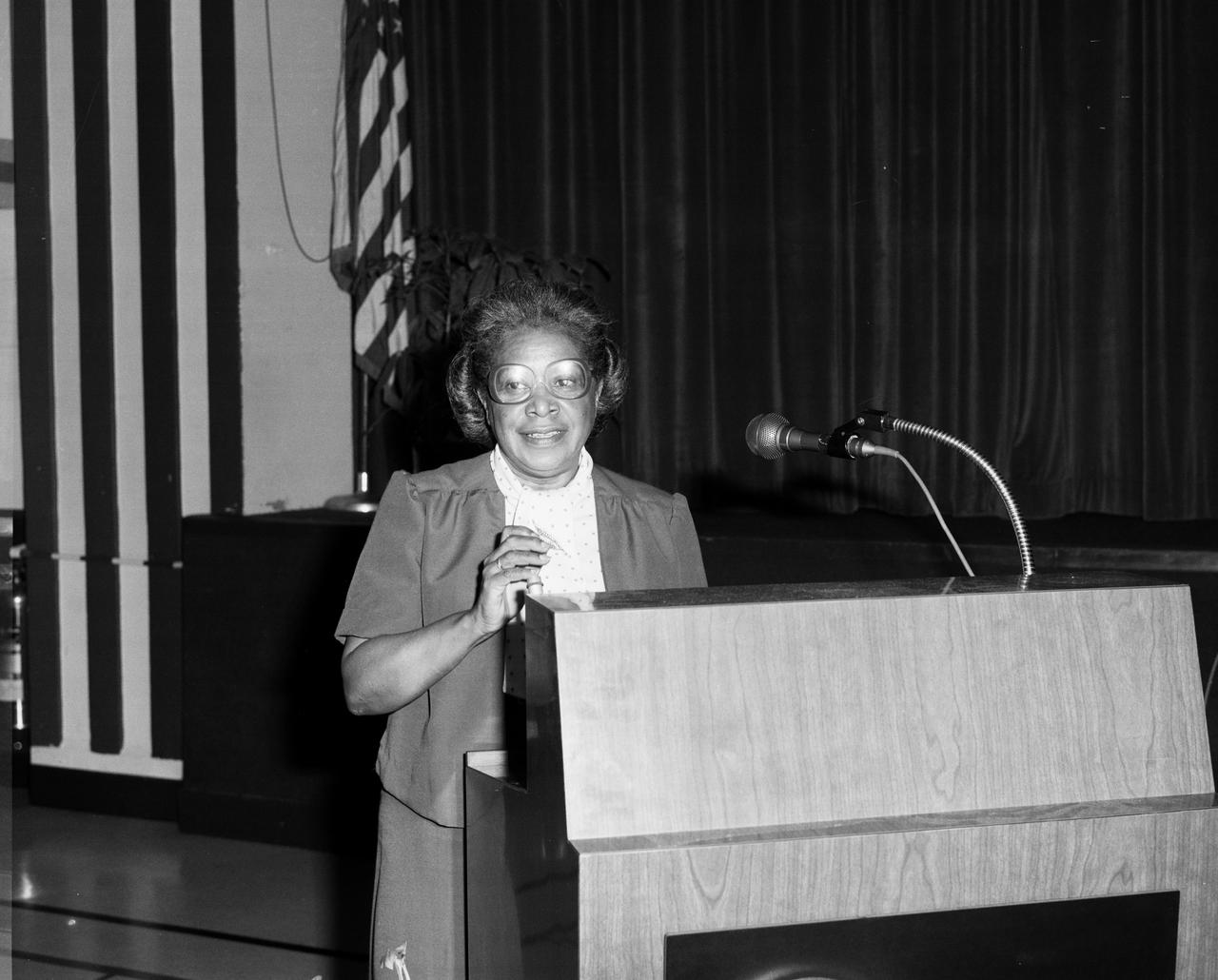
Federal Woman's Week, 1980 Various speakers, lecture groups, Mary Jackson in second from the left in this photo.
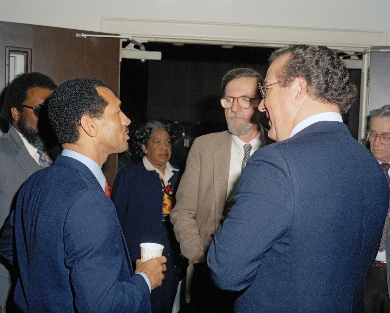
Photograph taken November 8, 1984. Student Symposium Meeting Mary Jackson in background. Both Mary Jackson and Katherine Johnson are women featured in the book Hidden Figures, by Margot Lee Shetterly. Man facing camera with glasses is center director Dr. Donald Hearth.
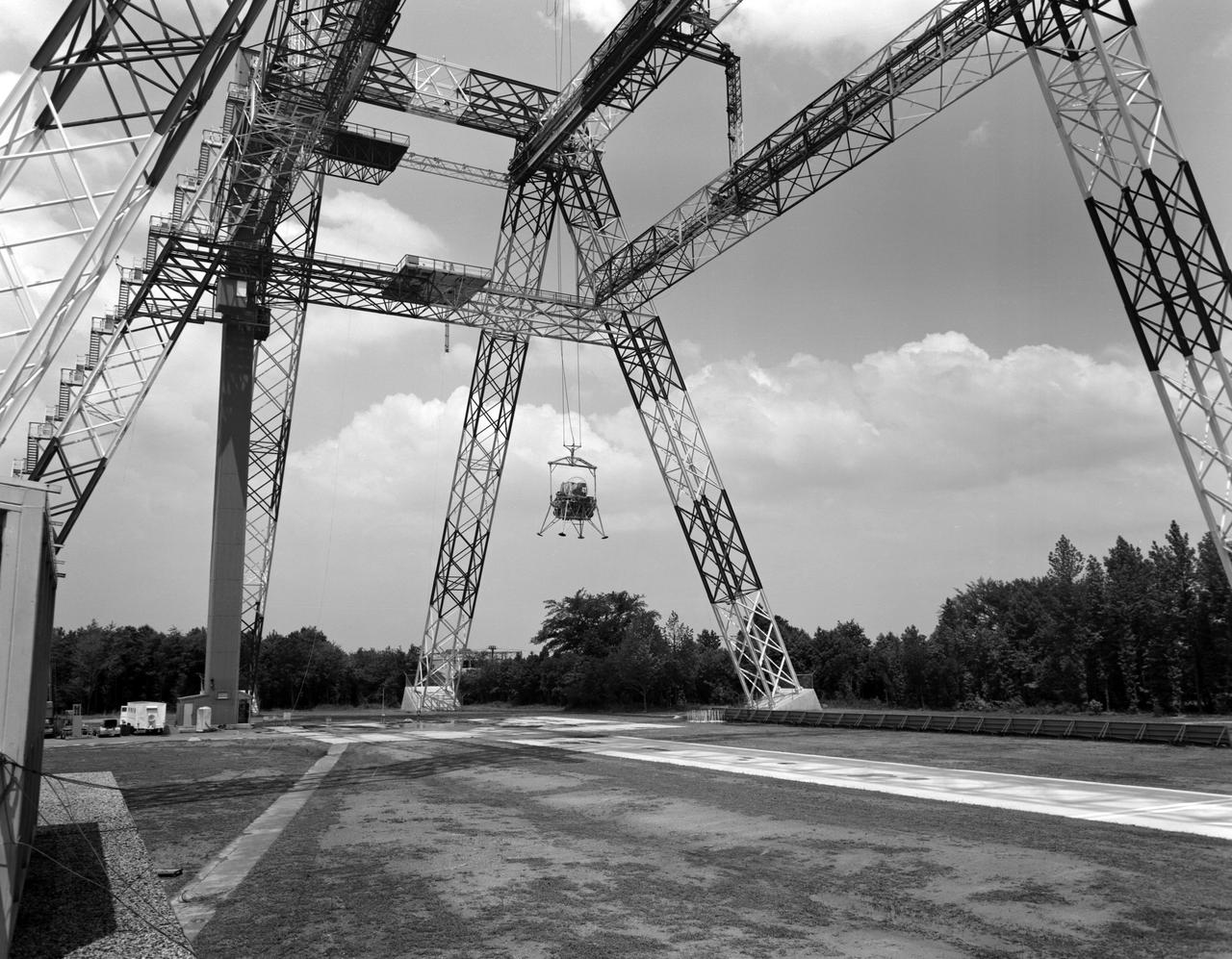
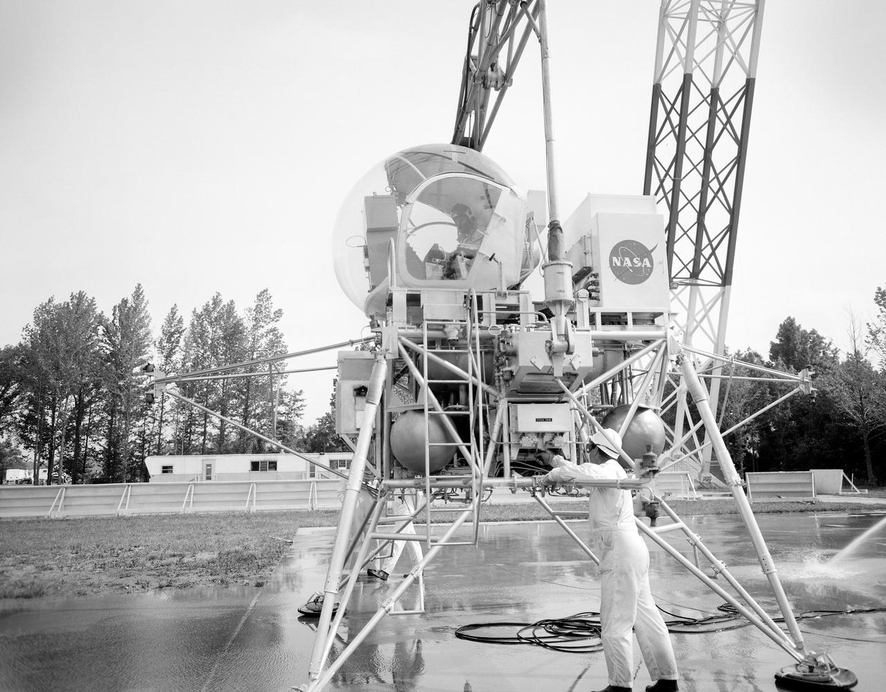
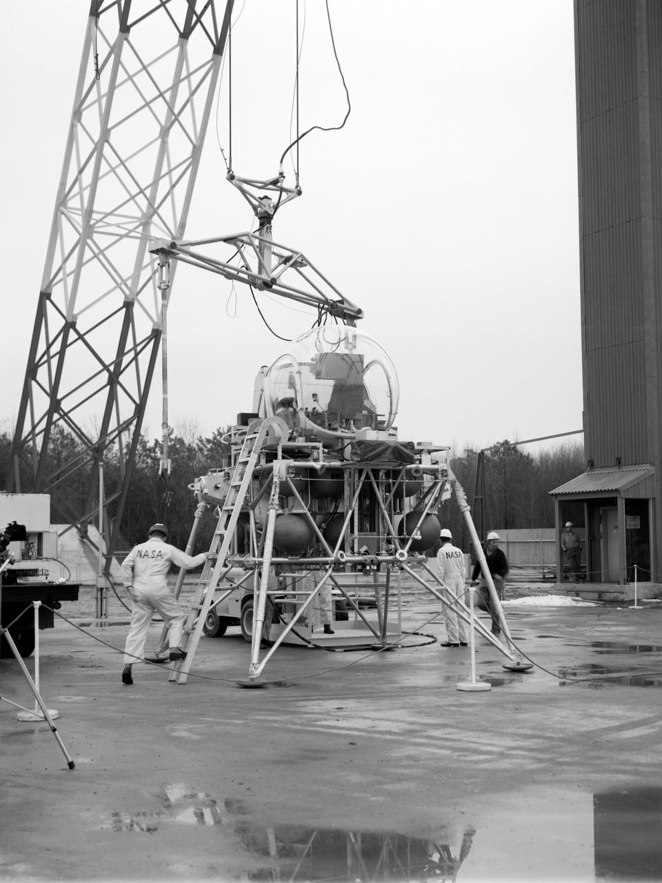
The Lunar Landing Research Facility at Langley Research Center has been put into operation. The facility, 250 feet high and 400 feet long, provides a controlled laboratory in which NASA scientists will work with research pilots to explore and develop techniques for landing a rocket-powered vehicle on the Moon, where the gravity is only one sixth as strong as on Earth. The Lunar Landing Research Facility, a controlled laboratory for exploring and developing techniques for landing a rocket-powered vehicle on the Moon, has been put into operation at the Langley Research Center. The $3.5 million facility includes a rocket-powered piloted flight test vehicle which is operated· while partially supported from a 250-foot high, 400-foot long gantry structure to simulate the one-sixth earth gravity of the Moon in research to obtain data on the problems of lunar landing. Excerpt from Langley Researcher July 2, 1965
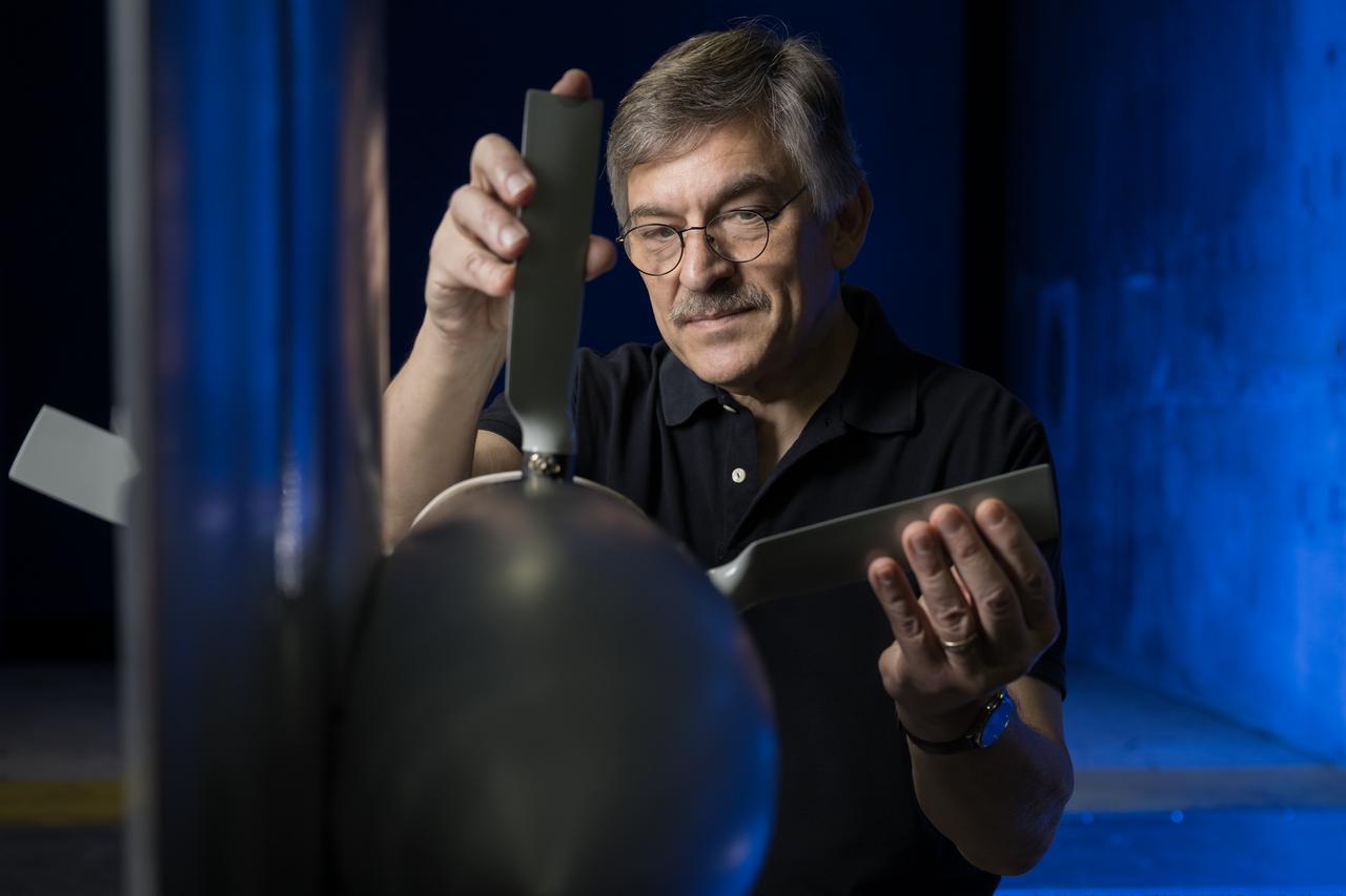
NASA researcher Norman W. Schaeffler adjusts a propellor, which is part of a 7-foot wing model that was recently tested at NASA’s Langley Research Center in Hampton, Virginia. In May and June, NASA researchers tested the wing in the 14-by-22-Foot Subsonic Wind Tunnel to collect data on critical propeller-wing interactions. The lessons learned from this testing will be shared with the public to support advanced air mobility aircraft development.
Lunar Landing Walking Simulator: Researchers at Langley study the ability of astronauts to walk, run and perform other tasks required during lunar exploration. The Reduced Gravity Simulator gave researchers the opportunity to look at the effects of one-sixth normal gravity on self-locomotion. Several Apollo astronauts practiced lunar waling at the facility.
Testing the External Vision System (XVS) software on the B200 King Air. Pilots, Peter Coen and Wayne Ringelberg attempt to spot an incoming aircraft on the XVS monitor.
Lunar landing test of LEM at Lunar Landing Research Facility (LLRF).
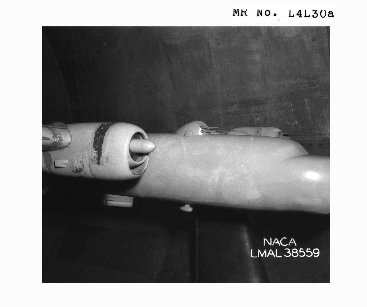
Detail Shots of B-32 Turret. B-33 Vega Turrets. Test conducted in the NACA 19 foot pressure tunnel LMAL-38560 NACA document.
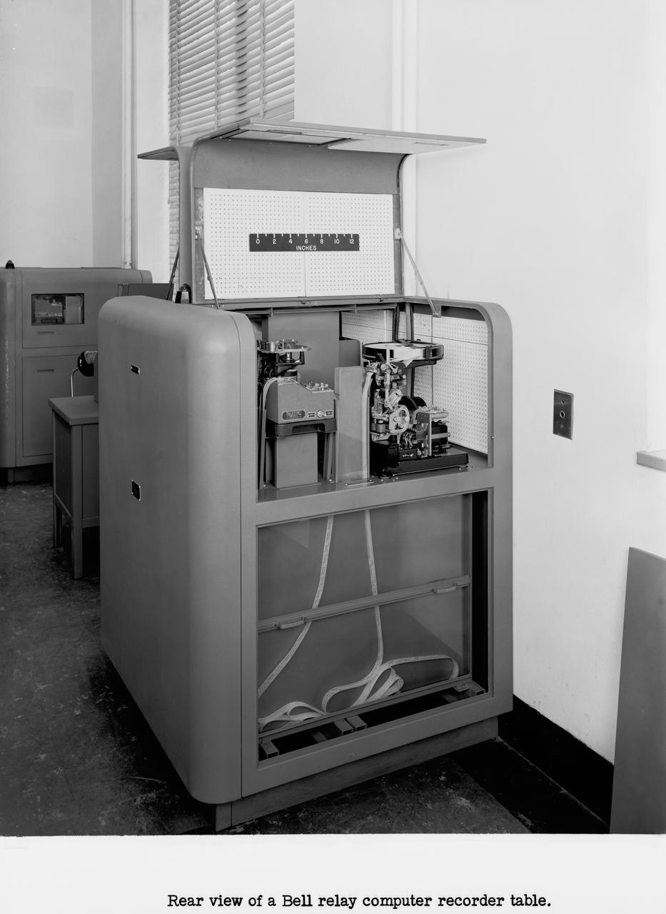
Langley's human computers at work in 1947. The female presence at Langley, who performed mathematical computations for male staff. Bell computers.