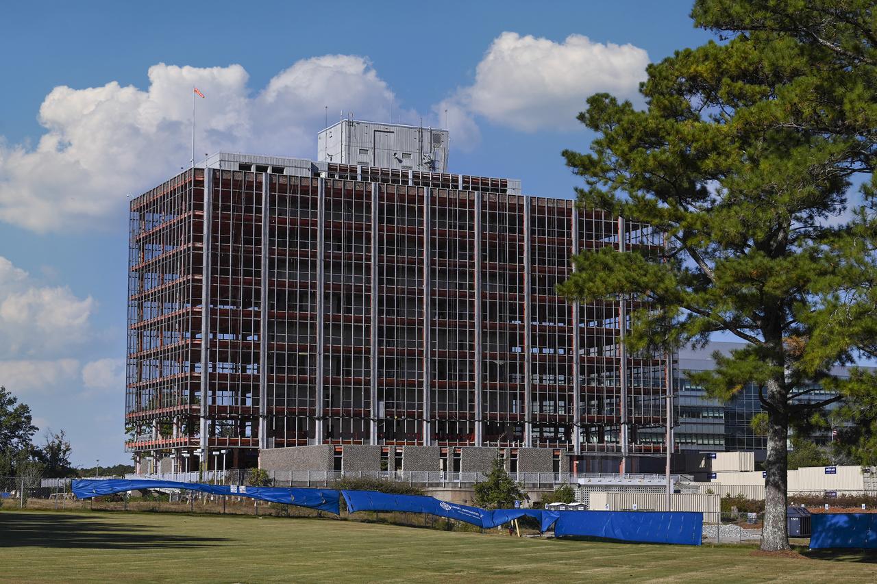
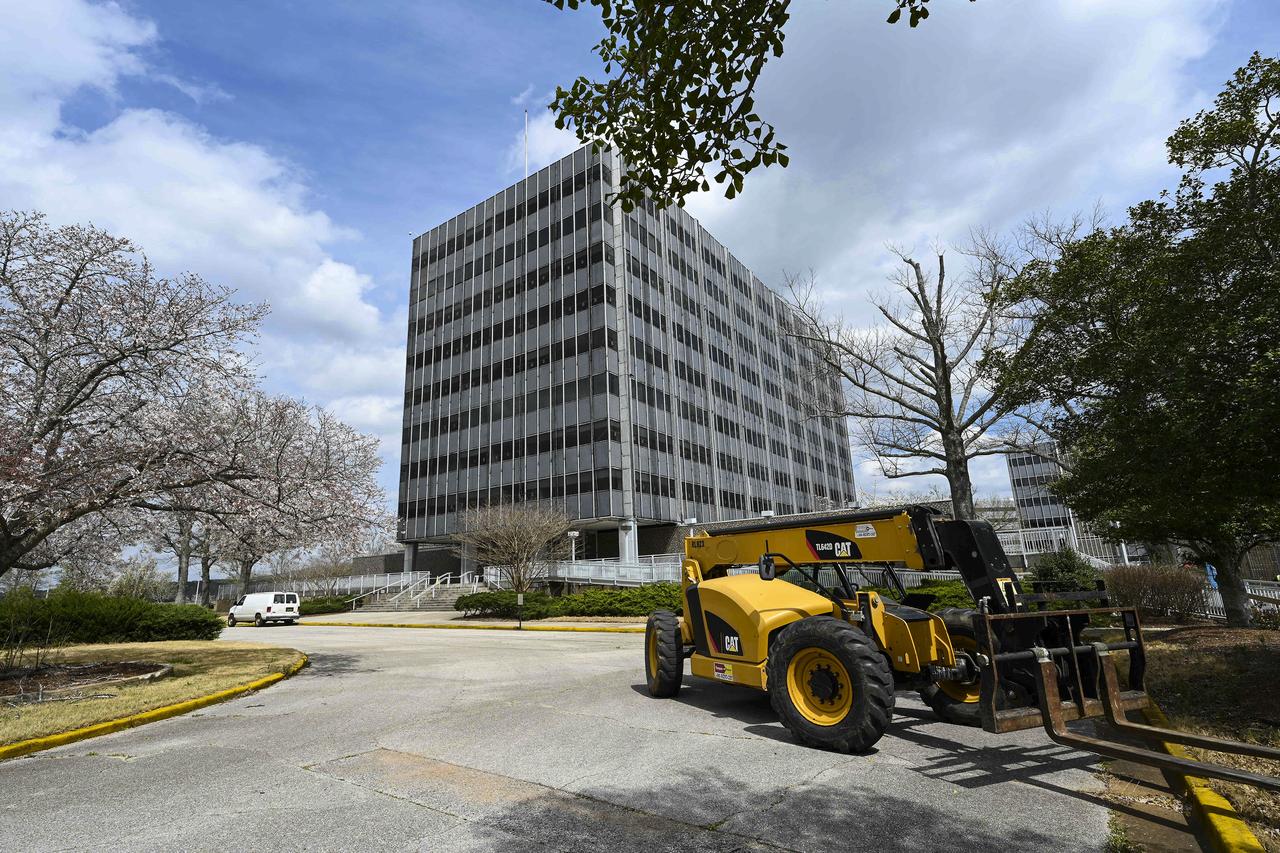
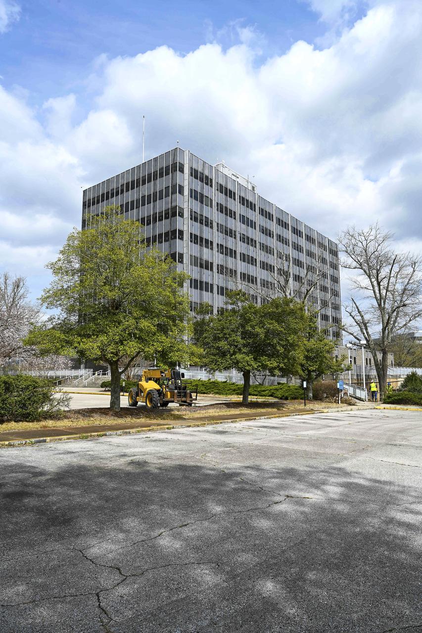
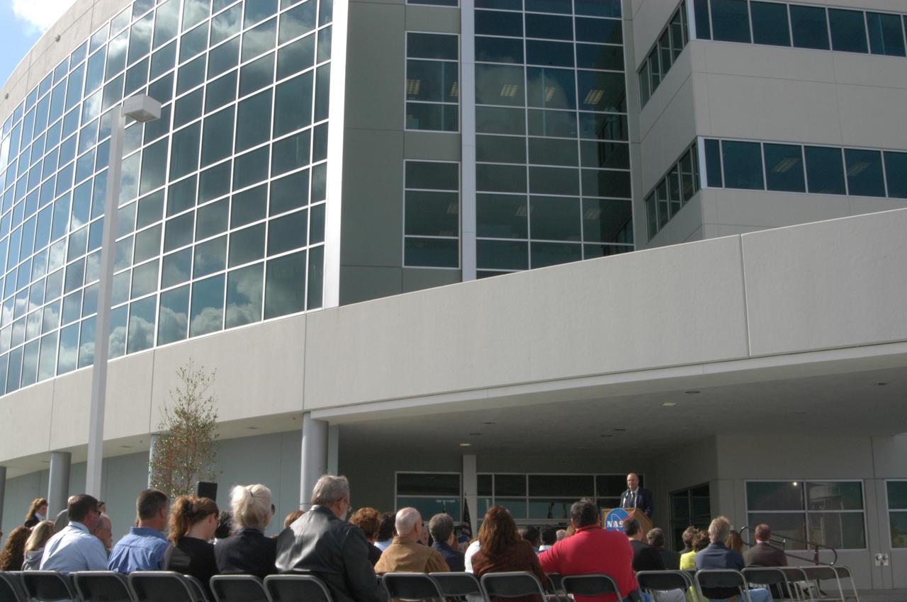
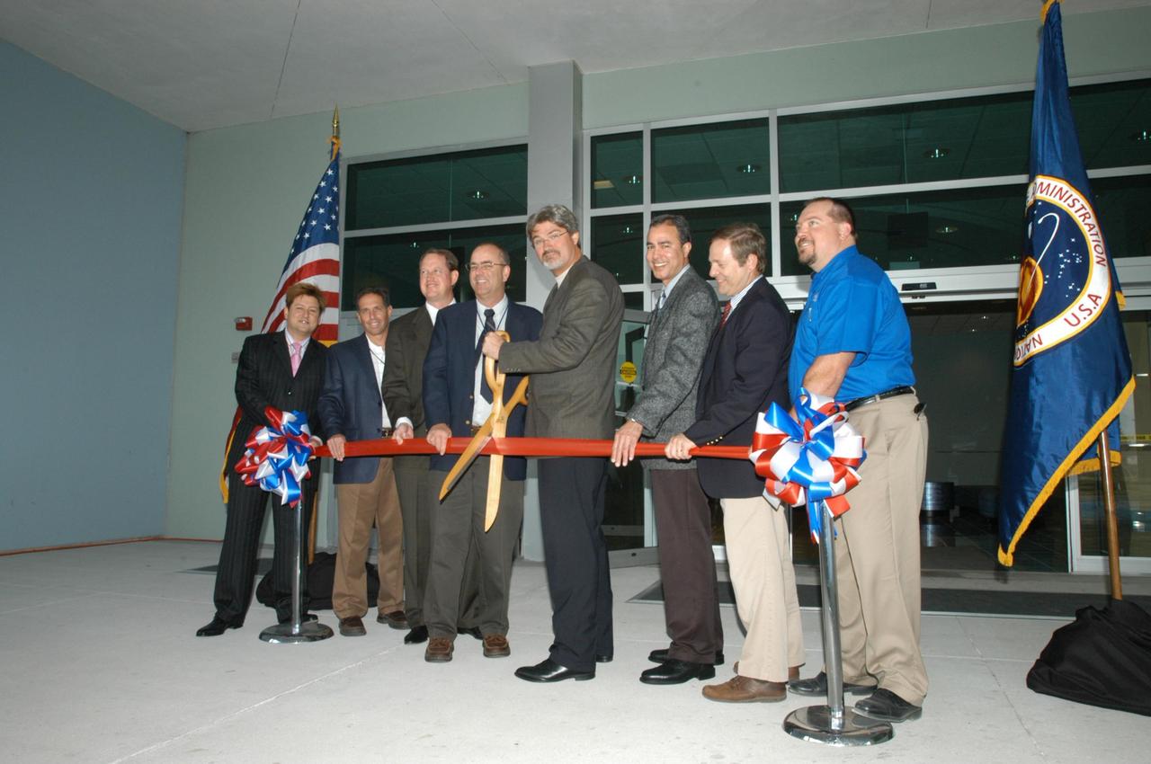
Exterior view of the Engineering Support Building (formerly Operations support Building)
lcJul171961
Exterior view of the Engineering Support Building (formerly Operations support Building)
lcJul1961
Aerial view of the Engineering Support Building (formerly Operations support Building)
lcSep1961
This archival image was released as part of a gallery comparing JPL’s past and present, commemorating the 80th anniversary of NASA’s Jet Propulsion Laboratory on Oct. 31, 2016.  Building 264, also known as the Space Flight Support Building, hosts engineers supporting space missions in flight at NASA's Jet Propulsion Laboratory. It used to be just two stories, as seen in this image from January 1972, but then the Viking project to Mars needed more room. The building still serves the same function today, but now has eight floors.  http://photojournal.jpl.nasa.gov/catalog/PIA21123
Space Flight Support Building
The engine vertical installer for NASA’s Space Launch System (SLS) is being lifted by crane in the Vehicle Assembly Building at NASA’s Kennedy Space Center in Florida on April 25, 2019. The engine installer arrived from the manufacturer, Precision Fabrication and Cleaning in Canaveral Groves, Florida. The new ground support equipment will be transferred into High Bay 3 where it will be ready for preflight processing in the event one of the four RS-25 engines on the core stage of the SLS rocket needs to be replaced. During launch of the SLS and Orion spacecraft, the four core stage engines will provide the thrust needed to lift the rocket and Orion spacecraft off Launch Pad 39B at Kennedy for Exploration Mission-1. The uncrewed Orion will travel on a three-week test mission thousands of miles beyond the Moon and back to Earth for a splashdown in the Pacific Ocean.
Engine Vertical Installer Arrival
The engine vertical installer for NASA’s Space Launch System (SLS) arrives by large transport truck at the Vehicle Assembly Building at NASA’s Kennedy Space Center in Florida on April 25, 2019. The engine installer arrived from the manufacturer, Precision Fabrication and Cleaning in Canaveral Groves, Florida. The new ground support equipment will be ready for preflight assembly in the event one of the four RS-25 engines on the core stage of the SLS rocket needs to be replaced. During launch of the SLS and Orion spacecraft, the four core stage engines will provide the thrust needed to lift the rocket and Orion spacecraft off Launch Pad 39B at Kennedy for Exploration Mission-1. The uncrewed Orion will travel on a three-week test mission thousands of miles beyond the Moon and back to Earth for a splashdown in the Pacific Ocean.
Engine Vertical Installer Arrival
The engine vertical installer for NASA’s Space Launch System (SLS) arrives by large transport truck at NASA’s Kennedy Space Center in Florida on April 25, 2019, from the manufacturer, Precision Fabrication and Cleaning in Canaveral Groves, Florida. The new ground support equipment will be delivered to the Vehicle Assembly Building where it will be ready for preflight assembly in the event one of the four RS-25 engines on the core stage of the SLS rocket needs to be replaced. During launch of the SLS and Orion spacecraft, the four core stage engines will provide the thrust needed to lift the rocket and Orion spacecraft off Launch Pad 39B at Kennedy for Exploration Mission-1. The uncrewed Orion will travel on a three-week test mission thousands of miles beyond the Moon and back to Earth for a splashdown in the Pacific Ocean.
Engine Vertical Installer Arrival
A banner signing event was held April 22, 2019, at NASA’s Kennedy Space Center in Florida, to mark the accomplishments of the Kennedy engineering team that supported the Ground Support Equipment (GSE) Subsystem Software development. The team gathered in the observation area of the Operations Support Building II with a view of the Vehicle Assembly Building behind them. This team includes the software leads, local developers, remote developers, modelers, project engineers, software quality assurance, build team members, integrators, system engineers, a chief engineer and some software managers. There are 60 unique instances of GSE Subsystem Software code. As of today, 58 of those 60 instances have completed software Level 5 Verification (L5V) and are in the process of completing Subsystem Verification & Validation.
KSC Engineering Banner Event
Building 4200 of Marshall’s administrative complex is prepared for demolition in the fall of 2022. Building 4200 was Marshall’s administrative headquarters from 1963 until 2020. The project will make way for a newer, more energy-efficient facilities, providing worksites for new generations of engineers, scientists, and support teams.
Site preparations underway for the phased decommissioning and re
Building 4200 of Marshall’s administrative complex is prepared for demolition in the fall of 2022. Building 4200 was Marshall’s administrative headquarters from 1963 until 2020. The project will make way for a newer, more energy-efficient facilities, providing worksites for new generations of engineers, scientists, and support teams.
Pre demolition photos of NASA MSFC building 4201 from the roof o
Building 4200 of Marshall’s administrative complex is prepared for demolition in the fall of 2022. Building 4200 was Marshall’s administrative headquarters from 1963 until 2020. The project will make way for a newer, more energy-efficient facilities, providing worksites for new generations of engineers, scientists, and support teams.
Site preparations underway for the phased decommissioning and re
Building 4200 of Marshall’s administrative complex is prepared for demolition in the fall of 2022. Building 4200 was Marshall’s administrative headquarters from 1963 until 2020. The project will make way for a newer, more energy-efficient facilities, providing worksites for new generations of engineers, scientists, and support teams.
NASA Marshall Space Flight Center campus buildings during demoli
A banner signing event was held April 22, 2019, at NASA’s Kennedy Space Center in Florida, to mark the accomplishments of the Kennedy engineering team that supported the Ground Support Equipment (GSE) Subsystem Software development. This team includes the software leads, local developers, remote developers, modelers, project engineers, software quality assurance, build team members, integrators, system engineers, a chief engineer and some software managers. There are 60 unique instances of GSE Subsystem Software code. As of today, 58 of those 60 instances have completed software Level 5 Verification (L5V) and are in the process of completing Subsystem Verification & Validation.
KSC Engineering Banner Event
KENNEDY SPACE CENTER, FLA. -  As the crawler transporter slowly moves the Mobile Launcher Platform (MLP) out of the Vehicle Assembly Building, the two solid rocket boosters on top are framed in the doorway.  The move is in support of engineering analysis vibration tests on the crawler and MLP.  The crawler is moving at various speeds up to 1 mph in an effort to achieve vibration data gathering goals as it leaves the VAB and then returns.  The boosters are braced at the top for stability.  The primary purpose of these rollout tests is to gather data to develop future maintenance requirements on the transport equipment and the flight hardware. Various parts of the MLP and crawler transporter have been instrumented with vibration data collection equipment.
KENNEDY SPACE CENTER, FLA. - As the crawler transporter slowly moves the Mobile Launcher Platform (MLP) out of the Vehicle Assembly Building, the two solid rocket boosters on top are framed in the doorway. The move is in support of engineering analysis vibration tests on the crawler and MLP. The crawler is moving at various speeds up to 1 mph in an effort to achieve vibration data gathering goals as it leaves the VAB and then returns. The boosters are braced at the top for stability. The primary purpose of these rollout tests is to gather data to develop future maintenance requirements on the transport equipment and the flight hardware. Various parts of the MLP and crawler transporter have been instrumented with vibration data collection equipment.
KENNEDY SPACE CENTER, FLA. -  The crawler transporter has slowly moved the Mobile Launcher Platform (MLP), carrying a set of twin solid rocket boosters, out of the Vehicle Assembly Building (VAB) in support of engineering analysis vibration tests on the crawler and MLP. The crawler is moving at various speeds up to 1 mph in an effort to achieve vibration data gathering goals as it leaves the VAB and then returns.  The boosters are braced at the top for stability.  The primary purpose of these rollout tests is to gather data to develop future maintenance requirements on the transport equipment and the flight hardware. Various parts of the MLP and crawler transporter have been instrumented with vibration data collection equipment.
KENNEDY SPACE CENTER, FLA. - The crawler transporter has slowly moved the Mobile Launcher Platform (MLP), carrying a set of twin solid rocket boosters, out of the Vehicle Assembly Building (VAB) in support of engineering analysis vibration tests on the crawler and MLP. The crawler is moving at various speeds up to 1 mph in an effort to achieve vibration data gathering goals as it leaves the VAB and then returns. The boosters are braced at the top for stability. The primary purpose of these rollout tests is to gather data to develop future maintenance requirements on the transport equipment and the flight hardware. Various parts of the MLP and crawler transporter have been instrumented with vibration data collection equipment.
KENNEDY SPACE CENTER, FLA. -  The crawler transporter slowly moves the Mobile Launcher Platform (MLP), carrying a set of twin solid rocket boosters, out of the Vehicle Assembly Building (VAB) in support of engineering analysis vibration tests on the crawler and MLP.   The crawler is moving at various speeds up to 1 mph in an effort to achieve vibration data gathering goals as it leaves the VAB and then returns.  The boosters are braced at the top for stability.  The primary purpose of these rollout tests is to gather data to develop future maintenance requirements on the transport equipment and the flight hardware. Various parts of the MLP and crawler transporter have been instrumented with vibration data collection equipment.
KENNEDY SPACE CENTER, FLA. - The crawler transporter slowly moves the Mobile Launcher Platform (MLP), carrying a set of twin solid rocket boosters, out of the Vehicle Assembly Building (VAB) in support of engineering analysis vibration tests on the crawler and MLP. The crawler is moving at various speeds up to 1 mph in an effort to achieve vibration data gathering goals as it leaves the VAB and then returns. The boosters are braced at the top for stability. The primary purpose of these rollout tests is to gather data to develop future maintenance requirements on the transport equipment and the flight hardware. Various parts of the MLP and crawler transporter have been instrumented with vibration data collection equipment.
KENNEDY SPACE CENTER, FLA. -  As the crawler transporter slowly moves the Mobile Launcher Platform (MLP) out of the Vehicle Assembly Building, the two solid rocket boosters on top are framed in the doorway.  The move is in support of engineering analysis vibration tests on the crawler and MLP. The crawler is moving at various speeds up to 1 mph in an effort to achieve vibration data gathering goals as it leaves the VAB and then returns.  The boosters are braced at the top for stability.  The primary purpose of these rollout tests is to gather data to develop future maintenance requirements on the transport equipment and the flight hardware. Various parts of the MLP and crawler transporter have been instrumented with vibration data collection equipment.
KENNEDY SPACE CENTER, FLA. - As the crawler transporter slowly moves the Mobile Launcher Platform (MLP) out of the Vehicle Assembly Building, the two solid rocket boosters on top are framed in the doorway. The move is in support of engineering analysis vibration tests on the crawler and MLP. The crawler is moving at various speeds up to 1 mph in an effort to achieve vibration data gathering goals as it leaves the VAB and then returns. The boosters are braced at the top for stability. The primary purpose of these rollout tests is to gather data to develop future maintenance requirements on the transport equipment and the flight hardware. Various parts of the MLP and crawler transporter have been instrumented with vibration data collection equipment.
KENNEDY SPACE CENTER, FLA. -  Mobile Launcher Platform (MLP) number 3 and a set of twin solid rocket boosters, atop the crawler-transporter, crawls away from the Vehicle Assembly Building in support of the second engineering analysis vibration test on the crawler and MLP. The crawler is moving at various speeds up to 1 mph in an effort to achieve vibration data gathering goals as it leaves the VAB, travels toward Launch Pad 39A and then returns.  The boosters are braced at the top for stability.  The primary purpose of these rollout tests is to gather data to develop future maintenance requirements on the transport equipment and the flight hardware. Various parts of the MLP and crawler transporter have been instrumented with vibration data collection equipment.
KENNEDY SPACE CENTER, FLA. - Mobile Launcher Platform (MLP) number 3 and a set of twin solid rocket boosters, atop the crawler-transporter, crawls away from the Vehicle Assembly Building in support of the second engineering analysis vibration test on the crawler and MLP. The crawler is moving at various speeds up to 1 mph in an effort to achieve vibration data gathering goals as it leaves the VAB, travels toward Launch Pad 39A and then returns. The boosters are braced at the top for stability. The primary purpose of these rollout tests is to gather data to develop future maintenance requirements on the transport equipment and the flight hardware. Various parts of the MLP and crawler transporter have been instrumented with vibration data collection equipment.
KENNEDY SPACE CENTER, FLA. -   The crawler transporter is slowly moving the Mobile Launcher Platform (MLP), carrying a set of twin solid rocket boosters, out of the Vehicle Assembly Building (VAB) in support of engineering analysis vibration tests on the crawler and MLP. The crawler is moving at various speeds up to 1 mph in an effort to achieve vibration data gathering goals as it leaves the VAB and then returns.  The boosters are braced at the top for stability.  The primary purpose of these rollout tests is to gather data to develop future maintenance requirements on the transport equipment and the flight hardware. Various parts of the MLP and crawler transporter have been instrumented with vibration data collection equipment.
KENNEDY SPACE CENTER, FLA. - The crawler transporter is slowly moving the Mobile Launcher Platform (MLP), carrying a set of twin solid rocket boosters, out of the Vehicle Assembly Building (VAB) in support of engineering analysis vibration tests on the crawler and MLP. The crawler is moving at various speeds up to 1 mph in an effort to achieve vibration data gathering goals as it leaves the VAB and then returns. The boosters are braced at the top for stability. The primary purpose of these rollout tests is to gather data to develop future maintenance requirements on the transport equipment and the flight hardware. Various parts of the MLP and crawler transporter have been instrumented with vibration data collection equipment.
KENNEDY SPACE CENTER, FLA. -  The crawler transporter slowly moves the Mobile Launcher Platform (MLP), carrying a set of twin solid rocket boosters, away from the Vehicle Assembly Building (VAB) in support of engineering analysis vibration tests on the crawler and MLP.   The crawler is moving at various speeds up to 1 mph in an effort to achieve vibration data gathering goals as it leaves the VAB and then returns.  The boosters are braced at the top for stability.  The primary purpose of these rollout tests is to gather data to develop future maintenance requirements on the transport equipment and the flight hardware. Various parts of the MLP and crawler transporter have been instrumented with vibration data collection equipment.
KENNEDY SPACE CENTER, FLA. - The crawler transporter slowly moves the Mobile Launcher Platform (MLP), carrying a set of twin solid rocket boosters, away from the Vehicle Assembly Building (VAB) in support of engineering analysis vibration tests on the crawler and MLP. The crawler is moving at various speeds up to 1 mph in an effort to achieve vibration data gathering goals as it leaves the VAB and then returns. The boosters are braced at the top for stability. The primary purpose of these rollout tests is to gather data to develop future maintenance requirements on the transport equipment and the flight hardware. Various parts of the MLP and crawler transporter have been instrumented with vibration data collection equipment.
Employees of the Engineering Directorate at NASA's Kennedy Space Center gather in the conference room of Operations Support Building II for a presentation by NASA Administrator Jim Bridenstine. He made his first official visit to the Florida spaceport on Aug. 6 and 7, 2018.
NASA Administrator Jim Bridenstine Visits KSC - Operations Suppo
Teams at NASA’s Kennedy Space Center in Florida installed four “quad pods” around the Artemis III core stage engine section inside the spaceport’s Space Systems Processing Facility on Tuesday, Sept. 10, 2024. These structures are used to support the engine assembly during operations. The engine section will be transferred to the NASA Kennedy’s Vehicle Assembly Building for final integration.
Artemis III Core Stage Engine Section
Engineers celebrate the completion of the Extensible Column Subsystem (XCS) project during a banner event held in Operations Support Building II at Kennedy Space Center. The XCS team successfully executed an aggressive schedule, receiving outstanding support from the fabrication contractor, Met-Con. Full functional testing occurred at Met-Con’s facility, with no mechanical or structural issues. All four columns and the test fixture have been delivered to Kennedy. Full-scale testing will take place when the Mobile Launcher gets to the pad later this summer.
KSC Engineering Banner Event
Kelly Jellison, avionics lead, and Tim Sandon, flight engineer, exit the DC-8 aircraft cabin and are welcomed with applause from a supportive team after the DC-8 aircraft and crew return to NASA’s Armstrong Flight Research Center Building 703 in Palmdale, California, on April 1, 2024, following the aircraft’s final mission in support of the Airborne and Satellite Investigation of Asian Air Quality (ASIA-AQ).
NASA’s DC-8 Returns from Final Mission
The Saturn IB and Saturn V first stages were manufactured at the Michoud Assembly Facility (MAF), located 24 kilometers (approximately 15 miles) east of downtown New Orleans, Louisiana. The basic manufacturing building boasted 43 acres under one roof. By 1964, NASA added a separate engineering and office building, vertical assembly building, and test stage building. By 1966, other changes to the site included enlarged barge facilities and other miscellaneous support buildings. The photograph shows Saturn V S-IC flight stages being assembled in the horizontal assembly area at the MAF.
Saturn Apollo Program
The Saturn IB and Saturn V flight vehicles first stages were manufactured at the Michoud Assembly Facility located 24 kilometers (approximately 15 miles) east of downtown New Orleans, Louisiana. The basic manufacturing building boasted 43 acres under one roof. By 1964, NASA added a separate engineering and office building, vertical assembly building, and test stage building. By 1966, other changes to the site included enlarged barge facilities and other miscellaneous support buildings. The image is a view of various vehicle components in the manufacturing plant.
Saturn Apollo Program
KENNEDY SPACE CENTER, FLA. --  Scott Kerr, director of Engineering Development at Kennedy Space Center, addresses guests at a ribbon-cutting ceremony for the Operations Support Building II (behind him). He and other key Center personnel and guests attended the significant event.  The Operations Support Building II is an Agency safety and health initiative project to replace 198,466 square feet of substandard modular housing and trailers in the Launch Complex 39 area at Kennedy Space Center.  The five-story building, which sits south of the Vehicle Assembly Building and faces the launch pads,  includes 960 office spaces, 16 training rooms, computer and multimedia conference rooms, a Mission Conference Center with an observation deck, technical libraries, an Exchange store, storage, break areas, and parking. Photo credit: NASA/George Shelton
KSC-06pd0546
Buildings 4201 (left) and 4200 (right) of Marshall’s administrative complex are seen in September 2022 as they were being prepared for demolition. Building 4200 was Marshall’s administrative headquarters from 1963 until 2020. The projects will make way for a series of newer, more energy-efficient facilities, providing worksites for new generations of engineers, scientists, and support teams.
Pre demolition photos of NASA MSFC building 4201 from the roof o
NASA DC-8 crew members Nickelle “Nicki” Reid, operations engineer, left, and Isac Mata, engineer technician, exchange in a heartfelt hug after the DC-8 aircraft and crew return to NASA Armstrong’s Building 703 in Palmdale, California, on April 1, 2024, following the aircraft’s final mission in support of the Airborne and Satellite Investigation of Asian Air Quality (ASIA-AQ). Smiling in the background is Michael Thomson, director of NASA Armstrong’s Science Mission Directorate.
NASA’s DC-8 Returns from Final Mission
NASA’s DC-8 operations engineer, Nickelle “Nicki” Reid, left, embraces Katherine Ball, chemical engineering Ph.D. candidate at California Institute of Technology, after the DC-8 aircraft and crew return to NASA Armstrong’s Building 703 in Palmdale, California, on April 1, 2024, following the aircraft’s final mission in support of the Airborne and Satellite Investigation of Asian Air Quality (ASIA-AQ).
NASA’s DC-8 Returns from Final Mission
The fuel tank assembly of the Saturn V S-IC (first) stage supported with the aid of a C frame on the transporter was readied to be transported to the Marshall Space Flight Center, building 4705. The fuel tank carried kerosene (RP-1) as its fuel. The S-IC stage utilized five F-1 engines that used kerosene and liquid oxygen as propellant and each engine provided 1,500,000 pounds of thrust. This stage lifted the entire vehicle and Apollo spacecraft from the launch pad.
Saturn Apollo Program
NASA Kennedy Space Center's Engineering Director Pat Simpkins signs the banner marking the successful delivery of a liquid oxygen test tank, called Tardis, in the Prototype Development Laboratory at NASA's Kennedy Space Center in Florida. Engineers and technicians worked together to develop the tank and build it to support cryogenic testing at Johnson Space Center's White Stands Test Facility in Las Cruces, New Mexico. The 12-foot-tall, 3,810-pound aluminum tank will be shipped to White Sands for testing.
NE TARDIS Banner Event
NASA Kennedy Space Center's Engineering Directorate held a banner signing event in the Prototype Development Laboratory to mark the successful delivery of a liquid oxygen test tank, called Tardis. Engineers and technicians worked together to develop the tank and build it to support cryogenic testing at Johnson Space Center's White Stands Test Facility in Las Cruces, New Mexico. The 12-foot-tall, 3,810-pound aluminum tank will be shipped to White Sands for testing.
NE TARDIS Banner Event
KENNEDY SPACE CENTER, FLA. -- -- Lifting their shovels for the groundbreaking of the Operations Support Building II are (left to right) Bill Pickavance, Vice President & Deputy Program Manager Florida Operations, United Space Alliance; Mike Wetmore, director of Shuttle Processing; Miguel Morales, chief, Facilities Division, Spaceport Services; Mike Sumner, chief of operations, Spaceport Services; David Wolfberg, designer of the facility, with Architect and Engineers Wolfberg, Alvarez and Partners of Coral Gables; Roy Bridges, KSC director; and Don Minderman, OSB II project manager, Spaceport Services.  Not shown:  David Boland, David Boland Inc.(construction company). The new building will replace modular housing constructed more than 20 years ago and house NASA and contractor support staff for shuttle operations.  The demolition of the modular buildings has begun and construction will immediately follow.  The new structure is projected to be ready in April 2005.
KSC-03pd0578
KENNEDY SPACE CENTER, FLA. --  With the ribbon-cutting ceremony, the new Operations Support Building II is officially in business.  Participating in the event are (left to right) Aris Garcia, vice president of the architecture firm Wolfgang Alvarez; Mark Nappi, associate program manager of Ground Operations for United Space Alliance; Donald Minderman, NASA project manager; Scott Kerr, director of Engineering Development at Kennedy; Bill Parsons, deputy director of Kennedy Space Center; Miguel Morales, with NASA Engineering Development; Mike Wetmore, director of Shuttle Processing; and Tim Clancy, president of the construction firm Clancy & Theys.   The Operations Support Building II is an Agency safety and health initiative project to replace 198,466 square feet of substandard modular housing and trailers in the Launch Complex 39 area at Kennedy Space Center.  The five-story building, which sits south of the Vehicle Assembly Building and faces the launch pads,  includes 960 office spaces, 16 training rooms, computer and multimedia conference rooms, a Mission Conference Center with an observation deck, technical libraries, an Exchange store, storage, break areas, and parking. Photo credit: NASA/George Shelton
KSC-06pd0547
CAPE CANAVERAL, Fla. -- Members of the crawlerway system evaluation team pose for a group portrait in front of the Headquarters Building at NASA's Kennedy Space Center in Florida.  The team received the Florida Project of the Year award from the American Society of Civil Engineers (ASCE).    The Cape Canaveral branch of the ASCE nominated the team for its project, the Crawlerway Evaluation to Support a Heavy-Lift Program. The crawlerway is a 130-foot-wide, specialty-built roadway between Kennedy's Vehicle Assembly Building (VAB), where rockets and spacecraft are prepared for flight, and Launch Pad 39A and 39B. The team's more than two-year evaluation confirmed the crawlerway system would be able to support the weight of moving the agency's future heavy-lift rockets and potential commercial vehicles from the VAB to the launch pads. The award honors the team's outstanding engineering efforts in research, design, construction and management, recognizing the complexity of multi-agency coordination and cost-effective engineering advances. For more information on the American Society of Civil Engineers, visit:  http://www.asce.org. Photo credit: NASA/Kim Shiflett
KSC-2011-7246
NASA Kennedy Space Center's Engineering Director Pat Simpkins, at left, talks with Michael E. Johnson, a project engineer; and Emilio Cruz, deputy division chief in the Laboratories, Development and Testing Division, inside the Prototype Development Laboratory. A banner signing event was held to mark the successful delivery of a liquid oxygen test tank, called Tardis. Engineers and technicians worked together to develop the tank and build it at the lab to support cryogenic testing at Johnson Space Center's White Sands Test Facility in Las Cruces, New Mexico. The 12-foot-tall, 3,810-pound aluminum tank will be shipped to White Sands for testing.
NE TARDIS Banner Event
The Marshall Space Flight Center (MSFC) is responsible for designing and building the life support systems that will provide the crew of the International Space Station (ISS) a comfortable environment in which to live and work. Scientists and engineers at the MSFC are working together to provide the ISS with systems that are safe, efficient, and cost-effective. These compact and powerful systems are collectively called the Environmental Control and Life Support Systems, or simply, ECLSS. This photograph shows the development Water Processor located in two racks in the ECLSS test area at the Marshall Space Flight Center. Actual waste water, simulating Space Station waste, is generated and processed through the hardware to evaluate the performance of technologies in the flight Water Processor design.
International Space Station (ISS)
Bob Myers, a mechanical systems engineer with ERC on the Test and Operations Support Contract, is inside the operator cab of crawler-transporter 2 on the crawlerway at NASA's Kennedy Space Center in Florida, on Aug. 27, 2018. CT-2 will carry the mobile launcher for the first time to Launch Pad 39B for a fit check of key systems that will support the launch of the agency's Space Launch System rocket and Orion spacecraft on Exploration Mission-1. The crawler also will carry the mobile launcher to the Vehicle Assembly Building for system checks and fit checks with the 10 levels of new work platforms in High Bay 3.
Crawler Transporter Drivers
Sam Dove, a crawler-transporter engineer with Jacobs on the Test and Operations Support Contract, stands in front of crawler-transporter 2 on the crawlerway at NASA's Kennedy Space Center in Florida, on Aug. 27, 2018. CT-2 will carry the mobile launcher for the first time to Launch Pad 39B for a fit check of key systems that will support the launch of the agency's Space Launch System rocket and Orion spacecraft on Exploration Mission-1. The crawler also will carry the mobile launcher to the Vehicle Assembly Building for system checks and fit checks with the 10 levels of new platforms in High Bay 3.
Crawler Transporter Drivers
Sam Dove, a crawler-transporter engineer with Jacobs on the Test and Operations Support Contract, is inside the operator cab of crawler-transporter 2 on the crawlerway at NASA's Kennedy Space Center in Florida, on Aug. 27, 2018. CT-2 will carry the mobile launcher for the first time to Launch Pad 39B for a fit check of key systems that will support the launch of the agency's Space Launch System rocket and Orion spacecraft on Exploration Mission-1. The crawler also will carry the mobile launcher to the Vehicle Assembly Building for system checks and fit checks with the 10 levels of new platforms in High Bay 3.
Crawler Transporter Drivers
Sam Dove, a crawler-transporter engineer with Jacobs on the Test and Operations Support Contract, is inside the operator cab of crawler-transporter 2 on the crawlerway at NASA's Kennedy Space Center in Florida, on Aug. 27, 2018. CT-2 will carry the mobile launcher for the first time to Launch Pad 39B for a fit check of key systems that will support the launch of the agency's Space Launch System rocket and Orion spacecraft on Exploration Mission-1. The crawler also will carry the mobile launcher to the Vehicle Assembly Building for system checks and fit checks with the 10 levels of new work platforms in High Bay 3.
Crawler Transporter Drivers
This picture is a view of stacking the major components of the S-IC (first) stage of the Saturn V vehicle at the Boeing vertical assembly building at the Michoud Assembly Facility (MAF). The view shows the S-IC forward skirt being lowered onto the liquid oxygen (LOX) tank. The Saturn IB and Saturn V first stages were manufactured at the MAF located 24 kilometers (approximately 15 miles) east of downtown New Orleans, Louisiana. The prime contractors, Chrysler and Boeing, jointly occupied the MAF. The basic manufacturing building boasted 43 acres under one roof. By 1964, NASA added a separate engineering and office building, vertical assembly building, and test stage building. By 1966, other changes to the site included enlarged barge facilities and other miscellaneous support buildings.
Saturn Apollo Program
This photograph is a view of stacking the major components of the S-IC (first) stage of the Saturn V vehicle at the Boeing vertical assembly building at the Michoud Assembly Facility (MAF). The view shows the Saturn V S-IC (first) stage thrust structure being placed for the final assembly. The Saturn IB and Saturn V first stages were manufactured at the MAF located 24 kilometers (approximately 15 miles) east of downtown New Orleans, Louisiana. The prime contractors, Chrysler and Boeing, jointly occupied the MAF. The basic manufacturing building boasted 43 acres under one roof. By 1964, NASA added a separate engineering and office building, vertical assembly building, and test stage building. By 1966, other changes to the site included enlarged barge facilities and other miscellaneous support buildings.
Saturn Apollo Program
This photograph is a view of stacking the major components of the S-IC (first) stage of the Saturn V vehicle at the Boeing vertical assembly building at the Michoud Assembly Facility (MAF). The view shows placing the liquid oxygen tank on the intertank and the fuel tank assembly. The Saturn IB and Saturn V first stages were manufactured at the MAF located 24 kilometers (approximately 15 miles) east of downtown New Orleans, Louisiana. The prime contractors, Chrysler and Boeing, jointly occupied the MAF. The basic manufacturing building boasted 43 acres under one roof. By 1964, NASA added a separate engineering and office building, vertical assembly building, and test stage building. By 1966, other changes to the site included enlarged barge facilities and other miscellaneous support buildings.
Saturn Apollo Program
This picture is a view of stacking the major components of the S-IC (first) stage of the Saturn V vehicle at the Boeing vertical assembly building at the Michoud Assembly Facility (MAF). The view shows the fuel tank being lowered into the thrust structure. The Saturn IB and Saturn V first stages were manufactured at the MAF located 24 kilometers (approximately 15 miles) east of downtown New Orleans, Louisiana. The prime contractors, Chrysler and Boeing, jointly occupied the MAF. The basic manufacturing building boasted 43 acres under one roof. By 1964, NASA added a separate engineering and office building, vertical assembly building, and test stage building. By 1966, other changes to the site included enlarged barge facilities and other miscellaneous support buildings.
Saturn Apollo Program
The Marshall Space Flight Center (MSFC) is responsible for designing and building the life support systems that will provide the crew of the International Space Station (ISS) a comfortable environment in which to live and work. Scientists and engineers at the MSFC are working together to provide the ISS with systems that are safe, efficient, and cost-effective. These compact and powerful systems are collectively called the Environmental Control and Life Support Systems, or simply, ECLSS. This is a view of the ECLSS and the Internal Thermal Control System (ITCS) Test Facility in building 4755, MSFC. In the foreground is the 3-module ECLSS simulator comprised of the U.S. Laboratory Module Simulator, Node 1 Simulator, and Node 3/Habitation Module Simulator. At center left is the ITCS Simulator. The main function of the ITCS is to control the temperature of equipment and hardware installed in a typical ISS Payload Rack.
International Space Station (ISS)
The Marshall Space Flight Center (MSFC) is responsible for designing and building the life support systems that will provide the crew of the International Space Station (ISS) a comfortable environment in which to live and work. Scientists and engineers at the MSFC are working together to provide the ISS with systems that are safe, efficient, and cost-effective. These compact and powerful systems are collectively called the Environmental Control and Life Support Systems, or simply, ECLSS. This is a view of the ECLSS and the Internal Thermal Control System (ITCS) Test Facility in building 4755, MSFC. In the foreground is the 3-module ECLSS simulator comprised of the U.S. Laboratory Module Simulator, Node 1 Simulator, and Node 3/Habitation Module Simulator. On the left is the ITCS Simulator. The main function of the ITCS is to control the temperature of equipment and hardware installed in a typical ISS Payload Rack.
International Space Station (ISS)
Inside the Prototype Development Laboratory at NASA's Kennedy Space Center in Florida, engineers and technicians hold a banner marking the successful delivery of a liquid oxygen test tank called Tardis. From left, are Todd Steinrock, chief, Fabrication and Development Branch, Prototype Development Lab; David McLaughlin, electrical engineering technician; Phil Stroda, mechanical engineering technician; Perry Dickey, lead electrical engineering technician; and Harold McAmis, lead mechanical engineering technician. Engineers and technicians worked together to develop the tank and build it at the lab to support cryogenic testing at Johnson Space Center's White Sands Test Facility in Las Cruces, New Mexico. The 12-foot-tall, 3,810-pound aluminum tank will be shipped to White Sands for testing.
NE TARDIS Banner Event
This photo gives an overhead look at an RS-88 development rocket engine being test fired at NASA's Marshall Space Flight Center in Huntsville, Alabama, in support of the Pad Abort Demonstration (PAD) test flights for NASA's Orbital Space Plane (OSP). The tests could be instrumental in developing the first crew launch escape system in almost 30 years. Paving the way for a series of integrated PAD test flights, the engine tests support development of a system that could pull a crew safely away from danger during liftoff. A series of 16 hot fire tests of a 50,000-pound thrust RS-88 rocket engine were conducted, resulting in a total of 55 seconds of successful engine operation. The engine is being developed by the Rocketdyne Propulsion and Power unit of the Boeing Company. Integrated launch abort demonstration tests in 2005 will use four RS-88 engines to separate a test vehicle from a test platform, simulating pulling a crewed vehicle away from an aborted launch. Four 156-foot parachutes will deploy and carry the vehicle to landing. Lockheed Martin is building the vehicles for the PAD tests. Seven integrated tests are plarned for 2005 and 2006.
Advanced Concept
In this photo, an RS-88 development rocket engine is being test fired at NASA's Marshall Space Flight Center in Huntsville, Alabama, in support of the Pad Abort Demonstration (PAD) test flights for NASA's Orbital Space Plane (OSP). The tests could be instrumental in developing the first crew launch escape system in almost 30 years. Paving the way for a series of integrated PAD test flights, the engine tests support development of a system that could pull a crew safely away from danger during liftoff. A series of 16 hot fire tests of a 50,000-pound thrust RS-88 rocket engine were conducted, resulting in a total of 55 seconds of successful engine operation. The engine is being developed by the Rocketdyne Propulsion and Power unit of the Boeing Company. Integrated launch abort demonstration tests in 2005 will use four RS-88 engines to separate a test vehicle from a test platform, simulating pulling a crewed vehicle away from an aborted launch. Four 156-foot parachutes will deploy and carry the vehicle to landing. Lockheed Martin is building the vehicles for the PAD tests. Seven integrated tests are plarned for 2005 and 2006.
Advanced Concept
A group of 19 college students recently visited NASA's Kennedy Space Center as winners of the First Nations Launch competition in Wisconsin. They were part of teams that successfully flew high-powered rockets, earning them an opportunity to visit the Florida spaceport. During their visit, they toured the Vehicle Assembly Building, Launch Control Center and the Kennedy visitor complex. The competition is supported by NASA and the Wisconsin Space Grant Consortium. It provides an opportunity for students attending tribal colleges or universities, or who are members of a campus American Indian Science and Engineering Society, or AISES, chapter to design, build and launch a rocket at a competition in Kansasville, Wisconsin.
2017 First Nations Launch Competition Winners visit Kennedy Spac
CAPE CANAVERAL, Fla. -- In the conference room of Operations Support Building II at NASA's Kennedy Space Center in Florida, social media participants listen to a briefing on future agency programs by Billy Stover, a NASA Commercial Crew Program Safety engineer.      The social media participants gathered at the Florida spaceport for the launch of the Mars Atmosphere and Volatile Evolution, or MAVEN, spacecraft. Their visit included tours of key facilities and participating in presentations by key NASA leaders who updated the space agency's current efforts. Photo credit: NASA/Jim Grossman
KSC-2013-3989
Workers sign the banner marking the successful delivery of a liquid oxygen test tank, called Tardis, in the Prototype Development Laboratory at NASA's Kennedy Space Center in Florida. Engineers and technicians worked together to develop the tank and build it at the lab to support cryogenic testing at Johnson Space Center's White Sands Test Facility in Las Cruces, New Mexico. The 12-foot-tall, 3,810-pound aluminum tank will be shipped to White Sands for testing.
NE TARDIS Banner Event
MATERIALS ENGINEER LARRY PELHAM OF NASA’S MARSHALL SPACE FLIGHT CENTER IN HUNTSVILLE, ALABAMA, OPERATES THE CEUS AUTOMATED FIBER PLACEMENT CYLINDRICAL MANUFACTURING TOOL IN BUILDING 4707. THE TOOL WILL BE USED BY THE COMPOSITES FOR EXPLORATION UPPER STAGE PROJECT AT MARSHALL, WHICH IS ANALYZING COMPOSITE MATERIALS TO SUPPORT FUTURE HARDWARE FOR NASA’S SPACE LAUNCH SYSTEM AND OTHER NEXT-GENERATION SPACECRAFT…
The CEUS automated fiber placement cylindrical manufacturing tool
Inside the Prototype Development Laboratory at NASA's Kennedy Space Center in Florida, workers in the lab hold a banner marking the successful delivery of a liquid oxygen test tank called Tardis. Engineers and technicians worked together to develop the tank to build it at the lab to support cryogenic testing at Johnson Space Center's White Sands Test Facility in Las Cruces, New Mexico. The 12-foot-tall, 3,810-pound aluminum tank will be shipped to White Sands for testing.
NE TARDIS Banner Event
Technicians and engineers with Jacobs on the Test and Operations Support Contract, prepare for a swing test of the Core Stage Inter-tank Umbilical (CSITU) on the mobile launcher in High Bay 3 of the Vehicle Assembly Building on Feb. 22, 2019, at NASA's Kennedy Space Center in Florida. The CSITU is a swing-arm umbilical that will connect to the Space Launch System core stage inter-tank. It will provide conditioned air, pressurized gases and power and data connection to the core stage. Exploration Ground Systems at Kennedy is conducting the swing test.
Mobile Launcher CSITU Swing Testing in VAB
KENNEDY SPACE CENTER, FLA.  - America's Space Shuttle stands poised on Launch Pad 39A, ready for Flight Readiness Firing of the main engines of the orbiter Columbia.  The Rotating Service Structure has been retracted in this view, moving the 'White Room' access to the Cargo Bay and other support facilities away from the exhaust damage zone.  This view was taken from the base of the approach ramp used by the Crawler when the Shuttle and its Mobile Launch Platform are moved from the Vehicle Assembly Building to the Pad.
KSC-81PC-0098
From left, Andy Barry, DC-8 pilot; Todd Renfro, flight navigator; and Adam Devalon, flight engineer, share smiles after the DC-8 aircraft and crew return to NASA’s Armstrong Flight Research Center Building 703 in Palmdale, California, on April 1, 2024, following the aircraft’s final mission in support of the Airborne and Satellite Investigation of Asian Air Quality (ASIA-AQ).
NASA’s DC-8 Returns from Final Mission
A liquid oxygen test tank was completed in the Prototype Development Laboratory at NASA's Kennedy Space Center in Florida. A banner signing event marked the successful delivery of the tank called Tardis.  Engineers and technicians worked together to develop the tank and build it at the lab to support cryogenic testing at Johnson Space Center's White Sands Test Facility in Las Cruces, New Mexico. The 12-foot-tall, 3,810-pound aluminum tank will be shipped to White Sands for testing.
NE TARDIS Banner Event
MATERIALS ENGINEER LARRY PELHAM OF NASA’S MARSHALL SPACE FLIGHT CENTER IN HUNTSVILLE, ALABAMA, OPERATES THE CEUS AUTOMATED FIBER PLACEMENT CYLINDRICAL MANUFACTURING TOOL IN BUILDING 4707. THE TOOL WILL BE USED BY THE COMPOSITES FOR EXPLORATION UPPER STAGE PROJECT AT MARSHALL, WHICH IS ANALYZING COMPOSITE MATERIALS TO SUPPORT FUTURE HARDWARE FOR NASA’S SPACE LAUNCH SYSTEM AND OTHER NEXT-GENERATION SPACECRAFT…
The CEUS automated fiber placement cylindrical manufacturing tool
Tim Linn, chief system engineer with Lockheed Martin, discusses the unique design of the OSIRIS-REx spacecraft during a NASA Social with social media followers in the Operations Support Building II at NASA’s Kennedy Space Center in Florida. The presentation took place before launch of the agency’s Origins, Spectral Interpretation, Resource Identification, Security-Regolith Explorer, or OSIRIS-REx spacecraft.
OSIRIS-REx NASA Social
Ivette Aponte, from Kennedy Space Center’s Engineering Directorate, sings the National Anthem at the “KSC and Proud to Be” centerwide diversity event held at the Florida spaceport’s Operations Support Building II (OSB II) on Aug. 20, 2019. The event featured a presentation by Robin Hauser, a director and producer of award-winning documentaries. Hauser, who has spoken at the White House and at conferences worldwide, addressed bias in artificial intelligence. A new employee video focusing on the importance of employee resource groups at the center made its debut showing at the event.
KSC and Proud to Be Center-Wide Diversity Event
Becky Murray, associate director of Engineering at NASA’s Kennedy Space Center in Florida, addresses Kennedy employees inside the Operations Support Building II on March 3, 2020, during the center’s annual Safety and Health Days. Taking place March 2 through March 6, Safety and Health Days provides Kennedy employees with a variety of presentations to attend – all of which focus on how to maintain a safe and healthy workforce.
Safety and Health Days - Work-Life Balance
CAPE CANAVERAL, Fla. – At NASA’s Kennedy Space Center in Florida, a worker views an exhibit on engineering designs in the Operations and Support Building II during the center’s 2012 Innovation Expo.    The center-wide event gave researchers a chance to show some of their work to others at the center and gave employees the opportunity to see facilities they hadn’t seen before. Photo credit: NASA/Kim Shiflett
KSC-2012-5010
Teams prepare for the installation of the engine nozzle onto the European Service Module for NASA’s Artemis III mission on Tuesday, Feb. 17, 2026, inside the high bay of the Neil A. Armstrong Operations and Checkout Building at NASA’s Kennedy Space Center in Florida. The service module provides the Orion spacecraft’s propulsion, thermal control, electrical power, and life support systems during the Artemis III mission to send humans to explore the lunar South Pole region.
Artemis III ESM3 Engine Nozzle Install Completion
KENNEDY SPACE CENTER, FLA. -  The crawler transporter slowly moves the Mobile Launcher Platform (MLP), carrying a set of twin solid rocket boosters, away from the Vehicle Assembly Building (VAB) in support of engineering analysis vibration tests on the crawler and MLP.   In the distance, at left, is Launch Pad 39A.  The water on the right of the crawlerway is the Banana River.  The crawler is moving at various speeds up to 1 mph in an effort to achieve vibration data gathering goals as it leaves the VAB and then returns.  The boosters are braced at the top for stability.  The primary purpose of these rollout tests is to gather data to develop future maintenance requirements on the transport equipment and the flight hardware. Various parts of the MLP and crawler transporter have been instrumented with vibration data collection equipment.
KENNEDY SPACE CENTER, FLA. - The crawler transporter slowly moves the Mobile Launcher Platform (MLP), carrying a set of twin solid rocket boosters, away from the Vehicle Assembly Building (VAB) in support of engineering analysis vibration tests on the crawler and MLP. In the distance, at left, is Launch Pad 39A. The water on the right of the crawlerway is the Banana River. The crawler is moving at various speeds up to 1 mph in an effort to achieve vibration data gathering goals as it leaves the VAB and then returns. The boosters are braced at the top for stability. The primary purpose of these rollout tests is to gather data to develop future maintenance requirements on the transport equipment and the flight hardware. Various parts of the MLP and crawler transporter have been instrumented with vibration data collection equipment.
KENNEDY SPACE CENTER, FLA. -  The crawler transporter slowly moves the Mobile Launcher Platform (MLP), carrying a set of twin solid rocket boosters, away from the Vehicle Assembly Building (VAB) in support of engineering analysis vibration tests on the crawler and MLP.  On either side of the boosters on the horizon can be seen the two launch pads. The crawler is moving at various speeds up to 1 mph in an effort to achieve vibration data gathering goals as it leaves the VAB and then returns.  The boosters are braced at the top for stability.  The primary purpose of these rollout tests is to gather data to develop future maintenance requirements on the transport equipment and the flight hardware. Various parts of the MLP and crawler transporter have been instrumented with vibration data collection equipment.
KENNEDY SPACE CENTER, FLA. - The crawler transporter slowly moves the Mobile Launcher Platform (MLP), carrying a set of twin solid rocket boosters, away from the Vehicle Assembly Building (VAB) in support of engineering analysis vibration tests on the crawler and MLP. On either side of the boosters on the horizon can be seen the two launch pads. The crawler is moving at various speeds up to 1 mph in an effort to achieve vibration data gathering goals as it leaves the VAB and then returns. The boosters are braced at the top for stability. The primary purpose of these rollout tests is to gather data to develop future maintenance requirements on the transport equipment and the flight hardware. Various parts of the MLP and crawler transporter have been instrumented with vibration data collection equipment.
KENNEDY SPACE CENTER, FLA. - A crawler-transporter carrying Mobile Launcher Platform (MLP) number 3, with a set of twin solid rocket boosters bolted atop, crawls to the intersection in the crawlerway in support of the second engineering analysis vibration test on the crawler and MLP.  From this perspective, the Launch Control Center (left) and the 525-foot-tall Vehicle Assembly Building (right) in the background appear dwarfed by the 184-foot-tall boosters. The crawler is moving at various speeds up to 1 mph in an effort to achieve vibration data gathering goals as it leaves the VAB, travels toward Launch Pad 39A and then returns. The boosters are braced at the top for stability. The primary purpose of these rollout tests is to gather data to develop future maintenance requirements on the transport equipment and the flight hardware. Various parts of the MLP and crawler transporter have been instrumented with vibration data collection equipment.
KENNEDY SPACE CENTER, FLA. - A crawler-transporter carrying Mobile Launcher Platform (MLP) number 3, with a set of twin solid rocket boosters bolted atop, crawls to the intersection in the crawlerway in support of the second engineering analysis vibration test on the crawler and MLP. From this perspective, the Launch Control Center (left) and the 525-foot-tall Vehicle Assembly Building (right) in the background appear dwarfed by the 184-foot-tall boosters. The crawler is moving at various speeds up to 1 mph in an effort to achieve vibration data gathering goals as it leaves the VAB, travels toward Launch Pad 39A and then returns. The boosters are braced at the top for stability. The primary purpose of these rollout tests is to gather data to develop future maintenance requirements on the transport equipment and the flight hardware. Various parts of the MLP and crawler transporter have been instrumented with vibration data collection equipment.
KENNEDY SPACE CENTER, FLA. - Viewed across the turn basin in the Launch Complex 39 Area, the crawler transporter slowly moves the Mobile Launcher Platform (MLP), carrying a set of twin solid rocket boosters, away from the Vehicle Assembly Building (VAB).  The journey is in support of engineering analysis vibration tests on the crawler and MLP.  The water on the right of the crawlerway is the Banana River.  The crawler is moving at various speeds up to 1 mph in an effort to achieve vibration data gathering goals as it leaves the VAB and then returns.  The boosters are braced at the top for stability.  The primary purpose of these rollout tests is to gather data to develop future maintenance requirements on the transport equipment and the flight hardware. Various parts of the MLP and crawler transporter have been instrumented with vibration data collection equipment.
KENNEDY SPACE CENTER, FLA. - Viewed across the turn basin in the Launch Complex 39 Area, the crawler transporter slowly moves the Mobile Launcher Platform (MLP), carrying a set of twin solid rocket boosters, away from the Vehicle Assembly Building (VAB). The journey is in support of engineering analysis vibration tests on the crawler and MLP. The water on the right of the crawlerway is the Banana River. The crawler is moving at various speeds up to 1 mph in an effort to achieve vibration data gathering goals as it leaves the VAB and then returns. The boosters are braced at the top for stability. The primary purpose of these rollout tests is to gather data to develop future maintenance requirements on the transport equipment and the flight hardware. Various parts of the MLP and crawler transporter have been instrumented with vibration data collection equipment.
KENNEDY SPACE CENTER, FLA. -  Mobile Launcher Platform (MLP) number 3 and a set of twin solid rocket boosters, atop the crawler-transporter, crawl out of the Vehicle Assembly Building (VAB) in support of the second engineering analysis vibration test on the crawler and MLP. In the background is another MLP.  The crawler is moving at various speeds up to 1 mph in an effort to achieve vibration data gathering goals as it leaves the VAB, travels toward Launch Pad 39A and then returns.  The boosters are braced at the top for stability.  The primary purpose of these rollout tests is to gather data to develop future maintenance requirements on the transport equipment and the flight hardware. Various parts of the MLP and crawler transporter have been instrumented with vibration data collection equipment.
KENNEDY SPACE CENTER, FLA. - Mobile Launcher Platform (MLP) number 3 and a set of twin solid rocket boosters, atop the crawler-transporter, crawl out of the Vehicle Assembly Building (VAB) in support of the second engineering analysis vibration test on the crawler and MLP. In the background is another MLP. The crawler is moving at various speeds up to 1 mph in an effort to achieve vibration data gathering goals as it leaves the VAB, travels toward Launch Pad 39A and then returns. The boosters are braced at the top for stability. The primary purpose of these rollout tests is to gather data to develop future maintenance requirements on the transport equipment and the flight hardware. Various parts of the MLP and crawler transporter have been instrumented with vibration data collection equipment.
KENNEDY SPACE CENTER, FLA. -  Mobile Launcher Platform (MLP) number 3 and a set of twin solid rocket boosters, atop the crawler-transporter, inch away from the Vehicle Assembly Building (VAB) in support of the second engineering analysis vibration test on the crawler and MLP. The crawler is moving at various speeds up to 1 mph in an effort to achieve vibration data gathering goals as it leaves the VAB, travels toward Launch Pad 39A and then returns.  The boosters are braced at the top for stability.  The primary purpose of these rollout tests is to gather data to develop future maintenance requirements on the transport equipment and the flight hardware. Various parts of the MLP and crawler transporter have been instrumented with vibration data collection equipment.
KENNEDY SPACE CENTER, FLA. - Mobile Launcher Platform (MLP) number 3 and a set of twin solid rocket boosters, atop the crawler-transporter, inch away from the Vehicle Assembly Building (VAB) in support of the second engineering analysis vibration test on the crawler and MLP. The crawler is moving at various speeds up to 1 mph in an effort to achieve vibration data gathering goals as it leaves the VAB, travels toward Launch Pad 39A and then returns. The boosters are braced at the top for stability. The primary purpose of these rollout tests is to gather data to develop future maintenance requirements on the transport equipment and the flight hardware. Various parts of the MLP and crawler transporter have been instrumented with vibration data collection equipment.
KENNEDY SPACE CENTER, FLA. - The crawler-transporter carrying Mobile Launcher Platform (MLP) number 3, with a set of twin solid rocket boosters bolted atop, crawls to the intersection in the crawlerway in support of the second engineering analysis vibration test on the crawler and MLP.  From this perspective, the Launch Control Center (left) and the 525-foot-tall Vehicle Assembly Building (right) in the background appear dwarfed by the 184-foot-tall boosters. The crawler is moving at various speeds up to 1 mph in an effort to achieve vibration data gathering goals as it leaves the VAB, travels toward Launch Pad 39A and then returns. The boosters are braced at the top for stability. The primary purpose of these rollout tests is to gather data to develop future maintenance requirements on the transport equipment and the flight hardware. Various parts of the MLP and crawler transporter have been instrumented with vibration data collection equipment.
KENNEDY SPACE CENTER, FLA. - The crawler-transporter carrying Mobile Launcher Platform (MLP) number 3, with a set of twin solid rocket boosters bolted atop, crawls to the intersection in the crawlerway in support of the second engineering analysis vibration test on the crawler and MLP. From this perspective, the Launch Control Center (left) and the 525-foot-tall Vehicle Assembly Building (right) in the background appear dwarfed by the 184-foot-tall boosters. The crawler is moving at various speeds up to 1 mph in an effort to achieve vibration data gathering goals as it leaves the VAB, travels toward Launch Pad 39A and then returns. The boosters are braced at the top for stability. The primary purpose of these rollout tests is to gather data to develop future maintenance requirements on the transport equipment and the flight hardware. Various parts of the MLP and crawler transporter have been instrumented with vibration data collection equipment.
CAPE CANAVERAL, Fla. -- A backscatter device continues to give engineers data on the intertank region of space shuttle Discovery's external fuel tank while it is in the Vehicle Assembly Building at NASA's Kennedy Space Center in Florida. Engineers at various NASA centers are analyzing, testing and imaging the intertank's support beams, called stringers, to make sure the tank is structurally sound for flight.          Discovery's next launch opportunity to the International Space Station on the STS-133 mission is no earlier than Feb. 3, 2011. For more information on STS-133, visit www.nasa.gov/mission_pages/shuttle/shuttlemissions/sts133/. Photo credit: NASA/Jack Pfaller
KSC-2011-1007
CAPE CANAVERAL, Fla. -- In the conference room of Operations Support Building II at NASA's Kennedy Space Center in Florida, social media participants listen to a briefing on the Mars Atmosphere and Volatile Evolution, or MAVEN, mission by, Joseph Fust, an engineer with United Launch Alliance, left, and Michael Wolfman, agency Vehicle System engineer.       The social media participants gathered at the Florida spaceport for the launch of the Mars Atmosphere and Volatile Evolution, or MAVEN, spacecraft. Their visit included tours of key facilities and participating in presentations by key NASA leaders who updated the space agency's current efforts. Photo credit: NASA/Jim Grossman
KSC-2013-3984
CAPE CANAVERAL, Fla. -- In the conference room of Operations Support Building II at NASA's Kennedy Space Center in Florida, social media participants listen to a briefing on the Mars Atmosphere and Volatile Evolution, or MAVEN, mission by, Joseph Fust, an engineer with United Launch Alliance, left, and Michael Wolfman, agency Vehicle System engineer.         The social media participants gathered at the Florida spaceport for the launch of the Mars Atmosphere and Volatile Evolution, or MAVEN, spacecraft. Their visit included tours of key facilities and participating in presentations by key NASA leaders who updated the space agency's current efforts. Photo credit: NASA/Jim Grossman
KSC-2013-3983
A NASA engineer signs the banner inside a support building at the Launch Equipment Test Facility at Kennedy Space Center in Florida. Testing of the Core Stage Forward Skirt Umbilical (CSFSU) for NASA's Space Launch System is complete and the umbilical has been transported to the mobile launcher area. The umbilical will be prepared for installation on the tower of the mobile launcher. The CSFSU will be mated to the core stage forward skirt to provide commodities to the SLS rocket, and then disconnect and swing away before launch. Its main purpose is to provide conditioned air and gaseous nitrogen to the SLS Core Stage Forward Skirt. The center’s Engineering Directorate and the Ground Systems Development and Operations Program are overseeing processing and testing of the umbilicals.
Core Stage Forward Skirt Umbilical (CSFSU) Testing Complete
CAPE CANAVERAL, Fla. -- A backscatter device continues to give engineers data on the intertank region of space shuttle Discovery's external fuel tank while it is in the Vehicle Assembly Building at NASA's Kennedy Space Center in Florida. Engineers at various NASA centers are analyzing, testing and imaging the intertank's support beams, called stringers, to make sure the tank is structurally sound for flight.          Discovery's next launch opportunity to the International Space Station on the STS-133 mission is no earlier than Feb. 3, 2011. For more information on STS-133, visit www.nasa.gov/mission_pages/shuttle/shuttlemissions/sts133/. Photo credit: NASA/Jack Pfaller
KSC-2011-1009
Construction workers install the drive motor for the Altitude Wind Tunnel (AWT) in the Exhauster Building at the National Advisory Committee for Aeronautics (NACA) Aircraft Engine Research Laboratory. The AWT was capable of operating full-scale engines in air density, speed, and temperature similar to that found at high altitudes. The tunnel could produce wind speeds up to 500 miles per hour through a 20-foot-diameter test section at the standard operating altitude of 30,000 feet. The airflow was created by a large wooden fan near the tunnel’s southeast corner.       This photograph shows the installation of the 18,000-horsepower drive motor inside the adjoining Exhauster Building in July 1943. The General Electric motor, whose support frame is seen in this photograph, connected to a drive shaft that extended from the building, through the tunnel shell, and into a 12-bladed, 31-foot-diameter spruce wood fan. Flexible couplings on the shaft allowed for the movement of the shell. The corner of the Exhauster Building was built around the motor after its installation.    The General Electric induction motor could produce 10 to 410 revolutions per minute and create wind speeds up to 500 miles per hour, or Mach 0.63, at 30,000 feet. The AWT became operational in January 1944 and tested piston, turbojet and ramjet engines for nearly 20 years.
Altitude Wind Tunnel Drive Motor Installation
CAPE CANAVERAL, Fla. -- NASA managers at NASA's Kennedy Space Center in Florida show off the Florida Project of the Year trophies that the crawlerway system evaluation team received from the American Society of Civil Engineers (ASCE).  From left are Michael Benik, director of Center Operations; Pepper Phillips, manager of the 21st Century Ground Systems Program Office; and Russell Romanella, associate director for Engineering and Technical Operations.    The Cape Canaveral branch of the ASCE nominated the team for its project, the Crawlerway Evaluation to Support a Heavy-Lift Program. The crawlerway is a 130-foot-wide, specialty-built roadway between Kennedy's Vehicle Assembly Building (VAB), where rockets and spacecraft are prepared for flight, and Launch Pad 39A and 39B. The team's more than two-year evaluation confirmed the crawlerway system would be able to support the weight of moving the agency's future heavy-lift rockets and potential commercial vehicles from the VAB to the launch pads. The award honors the team's outstanding engineering efforts in research, design, construction and management, recognizing the complexity of multi-agency coordination and cost-effective engineering advances. For more information on the American Society of Civil Engineers, visit:  http://www.asce.org. Photo credit: NASA/Kim Shiflett
KSC-2011-7245
NASA astronaut Victor Glover views the core stage of the SLS (Space Launch System) rocket that will help power Artemis II at NASA’s Michoud Assembly Facility in New Orleans July 15. Glover will pilot Artemis II, the first crewed mission of NASA’s Artemis campaign. Crews moved the 212-foot-tall core stage with its four RS-25 engines to Building 110 at NASA Michoud prior to rolling it out to NASA’s Pegasus barge July 16 for delivery to NASA’s Kennedy Space Center in Florida. The core stage has two giant propellant tanks that collectively hold more than 733,000 gallons of super cold liquid propellant to feed the stage’s four RS-25 engines. Together, the engines produce more than 2 million pounds of thrust to help send astronauts inside NASA’s Orion spacecraft to venture around the Moon for Artemis II.  NASA is working to land the first woman, first person of color, and its first international partner astronaut on the Moon under Artemis. SLS is part of NASA’s backbone for deep space exploration, along with the Orion spacecraft, supporting ground systems, advanced spacesuits and rovers, the Gateway in orbit around the Moon, and commercial human landing systems. SLS is the only rocket that can send Orion, astronauts, and supplies to the Moon in a single launch.
NASA Astronaut Victor Glover Views Artemis II Rocket Stage at NASA Michoud