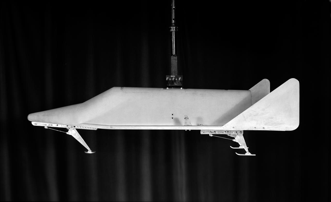
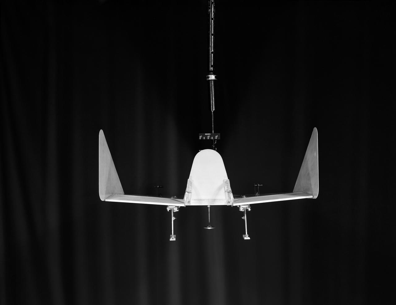
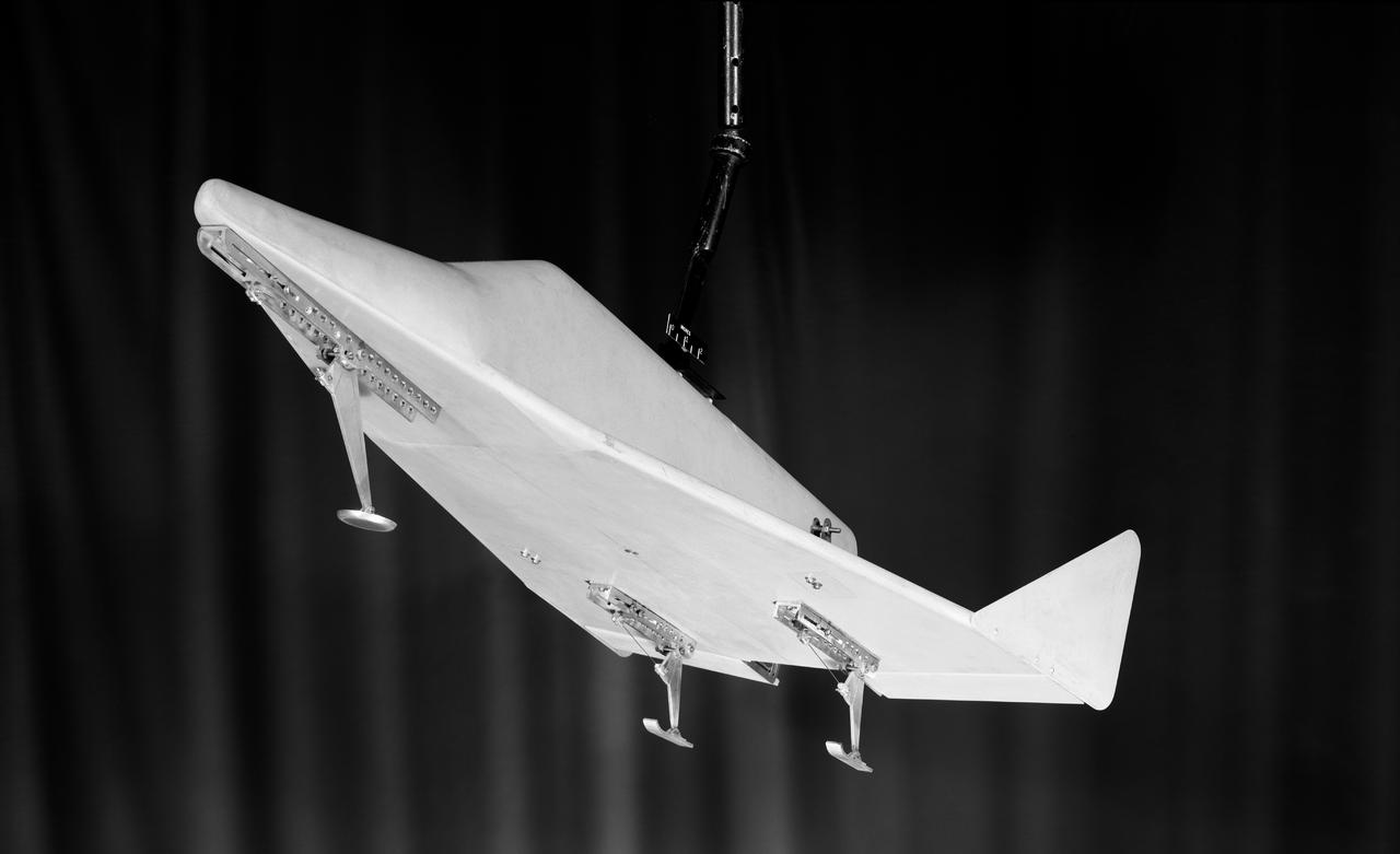
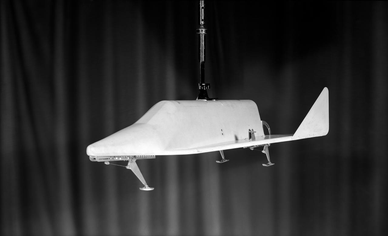
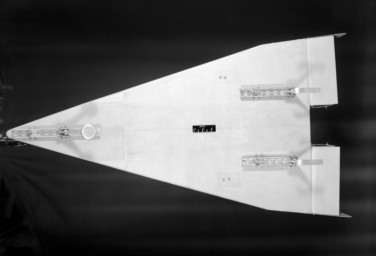
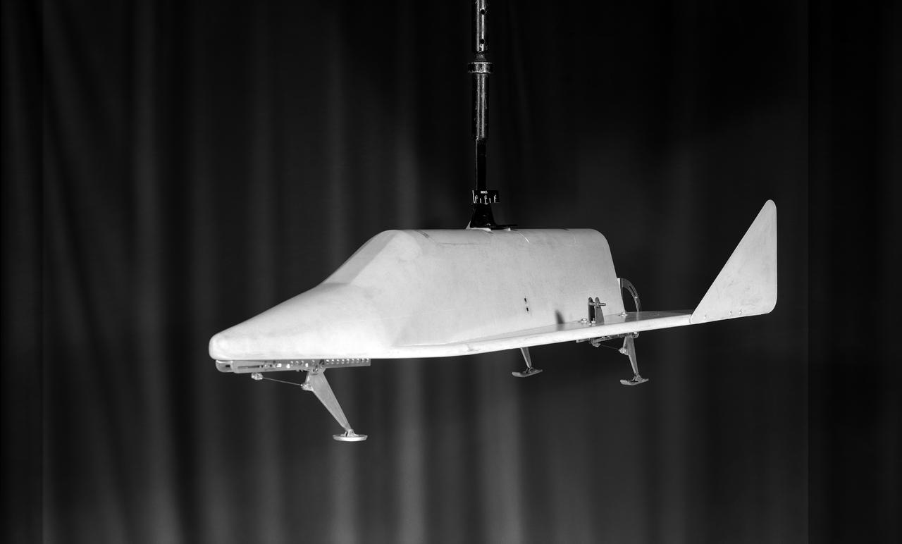
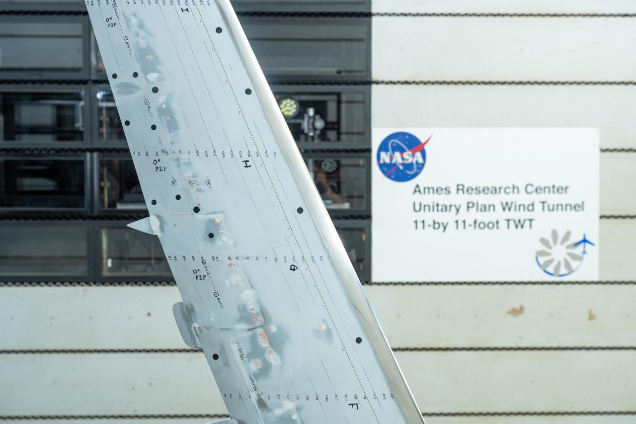
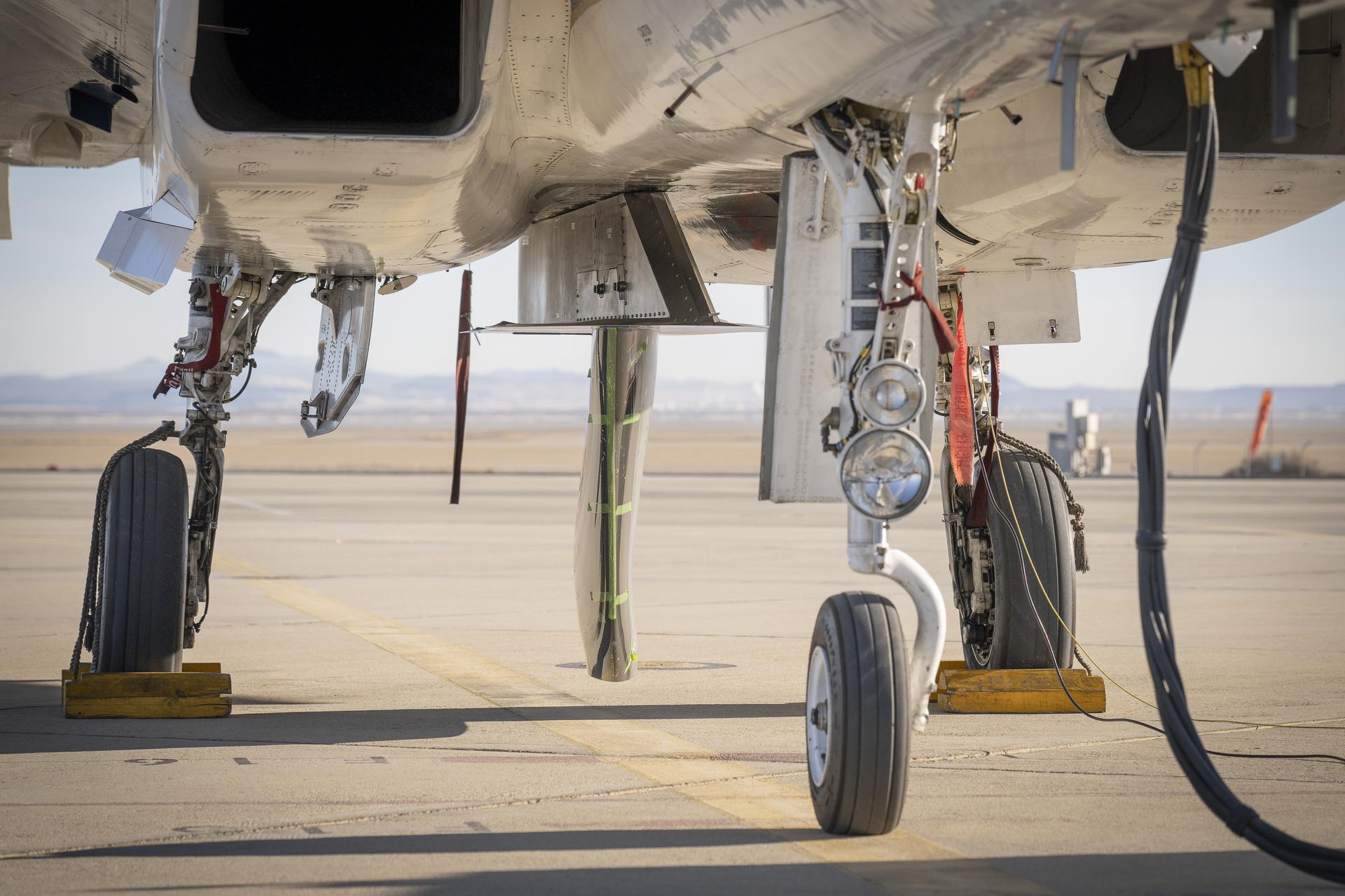
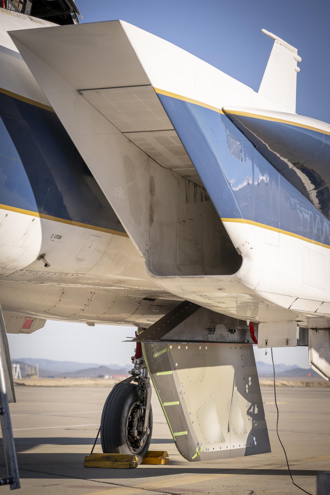
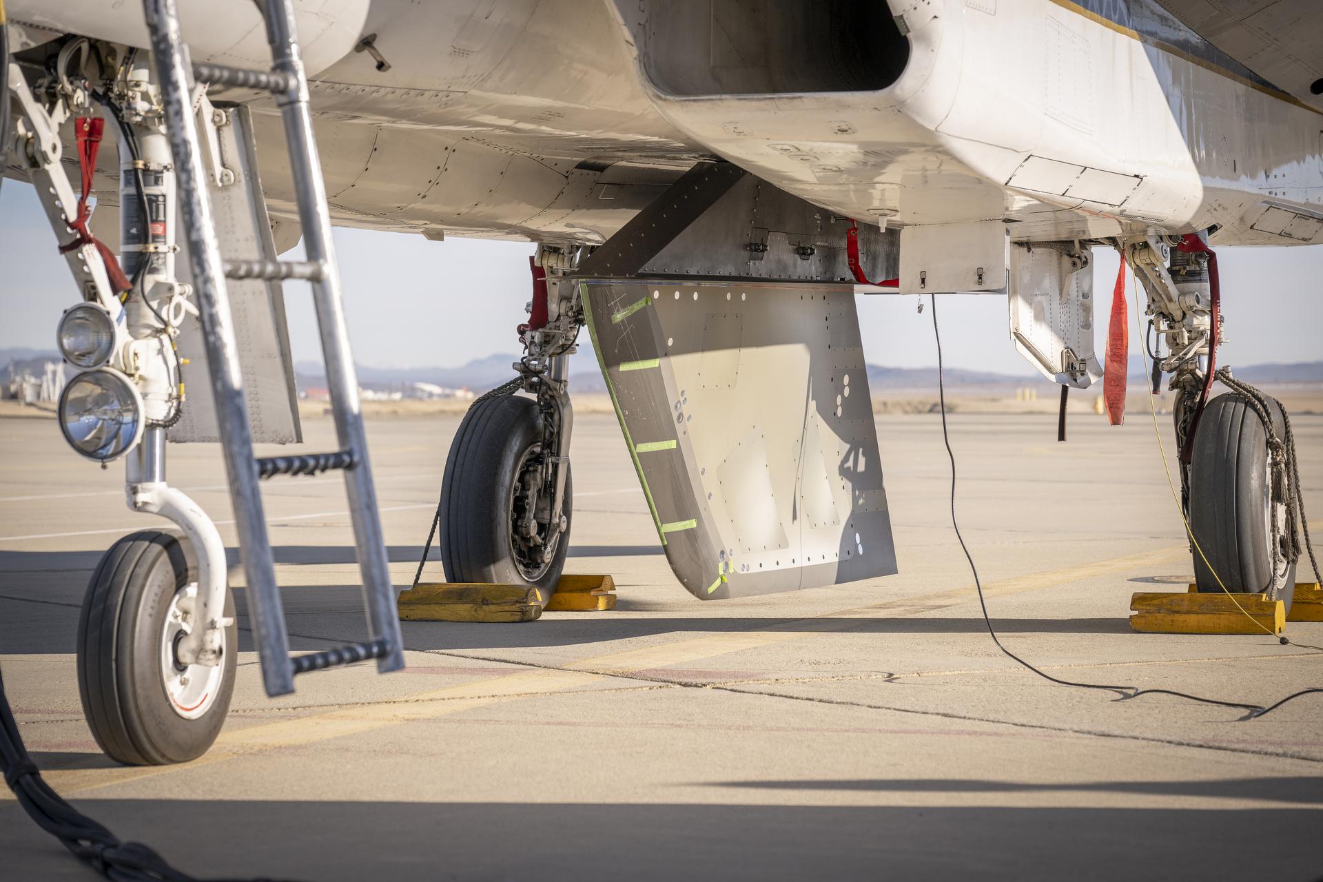
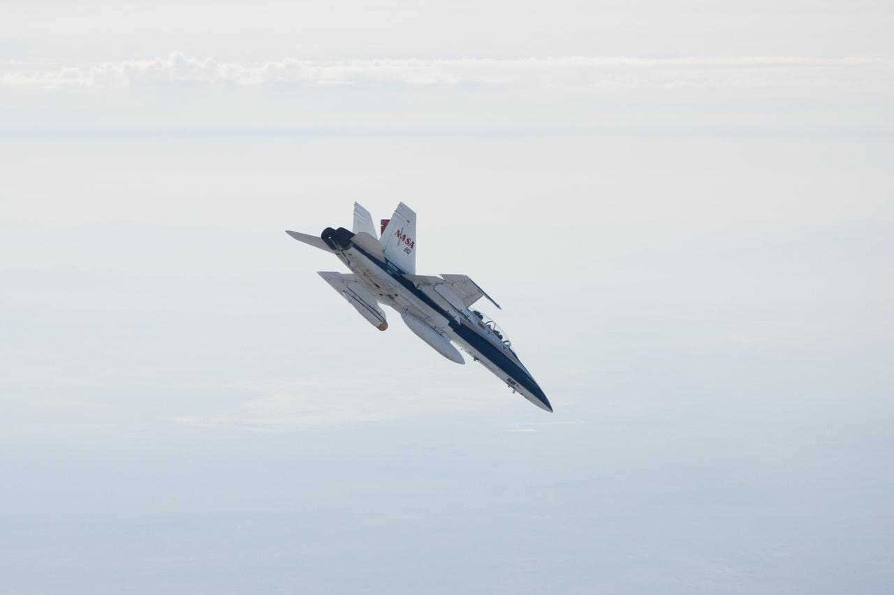
A chambered and twisted wing-body. Arrow wing hypersonic model tested in the 6x6 foot wind tunnel at the NASA Ames Research Center.
Arrow Wing Model in the 6x6 Foot Wind Tunnel at NASA Ames.
Investigation of a tilt-wing/propeller model with blowing flaps. 3/4 front view, tilt wing model, wing position = 0deg. C-123 fuselage, conventional struts, 4 props
Testing Tilt Wing Propeller Model in Ames 40x80 Foot Wind Tunnel.
3/4 front view from below of Delta wing Model with Nose Inlet in Ames 40x80 foot wind tunnel.
Delta Wing Test Model in Ames 40x80 Foot Wind Tunnel.
R.T. Jones Oblique Wing model: landing configuration
ARC-1972-A72-1961
R.T. Jones Oblique Wing model: flight configuration
ARC-1972-A72-1962
Model of Winged Space Vehicle
R.T. Jones w/ AD-1 Oblique Wing Models
ARC-1983-AC83-0662
R.T. Jones Oblique Wing model:  singal fuselage - 3 view artwork
ARC-1972-A72-1960
R.T. JONES OBLIQUE WING TRANSONIC TRANSPORT MODEL  2-BODY 'DOUBLE' FUSELAGE
ARC-1970-A70-5471
R.T. JONES OBLIQUE WING TRANSONIC TRANSPORT MODEL  2-BODY 'DOUBLE' FUSELAGE
ARC-1970-A70-5469
Tilt wing propeller model. 3/4 front view. 4 prop tilt wing nose down variable struts on ground board.  Leo Holl, NASA Ames Engineer.
Tilt Wing Propeller Model Tested in the Ames 40x80 Foot Wind Tunnel.
Wings for large scale model aircraft.
F8U-3 wing model Vought
de Havilland augmenter wing model 3/4 front view in 40 x 80 wind tunnel. JOHN CONWAY, ALAN WHEELBAND
de Havilland Augmenter Wing Model in Ames 40x80 foot Wind Tunnel.
(11/12/1971) 3/4 rear view of swept 75% scale augmentor wing quest model being installed into the test section of the Ames 40x80 foot wind tunnel, overhead doors open.
Swept Augmentor Wing Model Installed in the Ames 40X80 Foot Wind Tunnel.
Top front view of Delta wing lift fan fighter model.
Lift-Fan Delta Wing Fighter Model in Ames 40x80 foot Wind Tunnel.
Matthew Sanchez attaches the strut and the wing to ensure they fit together as intended for a 10-foot model of the Transonic Truss-Braced Wing at NASA’s Armstrong Flight Research Center, in Edwards, California. The aircraft concept involves a wing braced on an aircraft using diagonal struts that also add lift and could result in significantly improved aerodynamics.
NASA Armstrong Builds Model Wing
Matthew Sanchez assembles wing ribs for a 10-foot model of the Transonic Truss-Braced Wing at NASA’s Armstrong Flight Research Center, in Edwards, California. The aircraft concept involves a wing braced on an aircraft using diagonal struts that also add lift and could result in significantly improved aerodynamics.
NASA Armstrong Builds Model Wing
Matthew Sanchez assembles wing ribs to the 10-foot model of the Transonic Truss-Braced Wing at NASA’s Armstrong Flight Research Center, in Edwards, California. The aircraft concept involves a wing braced on an aircraft using diagonal struts that also add lift and could result in significantly improved aerodynamics.
NASA Armstrong Builds Model Wing
Matthew Sanchez attaches the strut and the wing to ensure they fit together as intended for a 10-foot model of the Transonic Truss-Braced Wing at NASA’s Armstrong Flight Research Center, in Edwards, California. The aircraft concept involves a wing braced on an aircraft using diagonal struts that also add lift and could result in significantly improved aerodynamics.
NASA Armstrong Builds Model Wing
Matthew Sanchez, left, consults with Sal Navarro on assembling wing ribs to the 10-foot model of the Transonic Truss-Braced Wing at NASA’s Armstrong Flight Research Center, in Edwards, California. The aircraft concept involves a wing braced on an aircraft using diagonal struts that also add lift and could result in significantly improved aerodynamics.
NASA Armstrong Builds Model Wing
LSAWT\Twin Jet Test with HWB Model\JEDA Measurements  Low Speed Aeroacoustic Wind Tunnel\Twin Jet Model System \Hybrid Wing Model Installed\ Measurement Technique: Jet Directional Array (JEDA)
LSAWT\Twin Jet Test with HWB Model\JEDA Measurements
LSAWT\Twin Jet Test with HWB Model\JEDA Measurements  Low Speed Aeroacoustic Wind Tunnel\Twin Jet Model System \Hybrid Wing Model Installed\ Measurement Technique: Jet Directional Array (JEDA)
LSAWT\Twin Jet Test with HWB Model\JEDA Measurements
LSAWT\Twin Jet Test with HWB Model\JEDA Measurements  Low Speed Aeroacoustic Wind Tunnel\Twin Jet Model System \Hybrid Wing Model Installed\ Measurement Technique: Jet Directional Array (JEDA)
LSAWT\Twin Jet Test with HWB Model\JEDA Measurements
Matthew Sanchez consults with Andrew Holguin on the strut for a 10-foot model of the Transonic Truss-Braced Wing at NASA’s Armstrong Flight Research Center, in Edwards, California. The aircraft concept involves a wing braced on an aircraft using diagonal struts that also add lift and could result in significantly improved aerodynamics.
NASA Armstrong Builds Model Wing
German Escobar works on milling the strut frame assembly for a 10-foot model of the Transonic Truss-Braced Wing at NASA’s Armstrong Flight Research Center, in Edwards, California. The aircraft concept involves a wing braced on an aircraft using diagonal struts that also add lift and could result in significantly improved aerodynamics.
NASA Armstrong Builds Model Wing
A milling machine drills holes in the strut frame assembly for a 10-foot model of the Transonic Truss-Braced Wing at NASA’s Armstrong Flight Research Center, in Edwards, California. The aircraft concept involves a wing braced on an aircraft using diagonal struts that also add lift and could result in significantly improved aerodynamics.
NASA Armstrong Builds Model Wing
Matthew Sanchez prepares a sheet of aluminum that will be cut into the outer layer of the strut for the 10-foot model of the Transonic Truss-Braced Wing at NASA’s Armstrong Flight Research Center, in Edwards, California. The aircraft concept involves a wing braced on an aircraft using diagonal struts that also add lift and could result in significantly improved aerodynamics.
NASA Armstrong Builds Model Wing
Jose Vasquez verifies a jury strut adaptor created for a 10-foot model of the Transonic Truss-Braced Wing at NASA’s Armstrong Flight Research Center, in Edwards, California. The aircraft concept involves a wing braced on an aircraft using diagonal struts that also add lift and could result in significantly improved aerodynamics.
NASA Armstrong Builds Model Wing
Aaron Rumsey and Beto Hinojos carefully add weight to a 6-foot model of the Transonic Truss-Braced Wing at NASA’s Armstrong Flight Research Center, in Edwards, California. The aircraft concept involves a wing braced on an aircraft using diagonal struts that also add lift and could result in significantly improved aerodynamics.
NASA Armstrong Tests Model Wing
A jury strut adaptor is created for a 10-foot model of the Transonic Truss-Braced Wing at NASA’s Armstrong Flight Research Center, in Edwards, California. The aircraft concept involves a wing braced on an aircraft using diagonal struts that also add lift and could result in significantly improved aerodynamics.
NASA Armstrong Builds Model Wing
Frank Pena and Benjamin Park watch as data streams in from tests on a 6-foot model of the Transonic Truss-Braced Wing at NASA’s Armstrong Flight Research Center, in Edwards, California.
NASA Armstrong Tests Model Wing
A machine cuts, rotates, and turns a block of aluminum to make a forward wing strut fastener for a 10-foot model of the Transonic Truss-Braced Wing at NASA’s Armstrong Flight Research Center, in Edwards, California. The aircraft concept involves a wing braced on an aircraft using diagonal struts that also add lift and could result in significantly improved aerodynamics.
NASA Armstrong Builds Model Wing
Matthew Sanchez places the strut and the wing side-by-side before assembling them for a check to ensure they fit together as intended for a 10-foot model of the Transonic Truss-Braced Wing at NASA’s Armstrong Flight Research Center, in Edwards, California. The aircraft concept involves a wing braced on an aircraft using diagonal struts that also add lift and could result in significantly improved aerodynamics.
NASA Armstrong Builds Model Wing
A block of aluminum is transformed by a machine programmed to cut, rotate, and turn it to make a forward wing strut fastener for a 10-foot model of the Transonic Truss-Braced Wing at NASA’s Armstrong Flight Research Center, in Edwards, California. The aircraft concept involves a wing braced on an aircraft using diagonal struts that also add lift and could result in significantly improved aerodynamics.
NASA Armstrong Builds Model Wing
Jose Vasquez uses a machine to cut, rotate and turn a block of aluminum to make a forward wing strut fastener for a 10-foot model of the Transonic Truss-Braced Wing at NASA’s Armstrong Flight Research Center, in Edwards, California. The aircraft concept involves a wing braced on an aircraft using diagonal struts that also add lift and could result in significantly improved aerodynamics.
NASA Armstrong Builds Model Wing
Jose Vasquez programed a machine to cut, rotate and turn a block of steel to form a jury strut adaptor for a 10-foot model of the Transonic Truss-Braced Wing at NASA’s Armstrong Flight Research Center, in Edwards, California. The aircraft concept involves a wing braced on an aircraft using diagonal struts that also add lift and could result in significantly improved aerodynamics.
NASA Armstrong Builds Model Wing
Matthew Sanchez uses a water jet to cut aluminum for the outer layer of the strut for the 10-foot model of the Transonic Truss-Braced Wing at NASA’s Armstrong Flight Research Center, in Edwards, California. The aircraft concept involves a wing braced on an aircraft using diagonal struts that also add lift and could result in significantly improved aerodynamics.
NASA Armstrong Builds Model Wing
Engineering technician Jeff Howell removes tape from the Mock Truss-Braced Wing 10-foot model at NASA’s Armstrong Flight Research Center in Edwards, California. The tape was used to limit the amount of epoxy on the model wing during the process to secure the fiber optic strain sensors to the wing.
NASA Prepares for Mock Truss-Braced Wing Tests
Project: Wing Sweep Range Series   TAC Variable Sweep Model configure 8 A. Taken at 8 foot tunnels building 641. L60-3412 through 3416 Model of proposed military supersonic attack airplane shows wing sweep range. TAC Models taken at the 8 Foot Tunnel. Photograph published in Sixty Years of Aeronautical Research 1917-1977 By David A. Anderton. A NASA publication. Page 53.
TAC Variable Sweep Model
(11/12/1971) 3/4 Scale swept augmentor wing Quest model being installed into the test section of the ames 40 x 80 foot wind tunnel, overhead doors open.
A71-8290. Swept Augmentor Wing Model Being Installed Into The Test Section Of The Ames 40 X 80 Foot Wind Tunnel.
Test Setup For Model Landing Investigation of a Winged Space Vehicle  Image used in NASA Document TN-D-1496  1960-L-04633.01 is Figure 9a for NASA Document L-2064 Photograph of model on launcher and landing on runway.
Test Setup For Model Landing Investigation of a Winged Space Vehicle
Test Setup For Model Landing Investigation of a Winged Space Vehicle  Image used in NASA Document TN-D-1496  1960-L-04633.01 is Figure 9a for NASA Document L-2064 Photograph of model on launcher and landing on runway.
Test Setup For Model Landing Investigation of a Winged Space Vehicle
Test Setup For Model Landing Investigation of a Winged Space Vehicle  Image used in NASA Document TN-D-1496  1960-L-04633.01 is Figure 9a for NASA Document L-2064 Photograph of model on launcher and landing on runway.
Test Setup For Model Landing Investigation of a Winged Space Vehicle
6x6 wind tunnel test on the effects of wing sweep.
SWEPT-BACK WING. MODEL IN 6X6' W.T.
Engineering technician Jeff Howell mounts conventional strain gauges to the Mock Truss-Braced Wing 10-foot model at NASA’s Armstrong Flight Research Center in Edwards, California. The conventional system data will be compared the Fiber Optic Sensing System developed at the center on the same wing to see how well the testing methods match.
NASA Prepares for Mock Truss-Braced Wing Tests
NASA’s Sustainable Flight Demonstrator project concluded wind tunnel testing in the fall of 2024. Tests on a Boeing-built X-66 model were completed at NASA’s Ames Research Center in Silicon Valley, California, in the 11-Foot Transonic Unitary Plan Facility. Pressure points, which are drilled holes with data sensors attached, are installed along the edge of the wing and allow engineers to understand the characteristics of airflow and will influence the final design of the wing.
Wind Over Its Wing: NASA’s X-66 Model Tests Airflow
NASA’s Sustainable Flight Demonstrator project concluded wind tunnel testing in the fall of 2024. Tests on a Boeing-built X-66 model were completed at NASA’s Ames Research Center in California’s Silicon Valley in the 11-Foot Transonic Unitary Plan Facility. The model underwent tests representing expected flight conditions to obtain engineering information to influence design of the wing and provide data for flight simulators.
Wind Over Its Wing: NASA’s X-66 Model Tests Airflow
Instrumentation of the wing and strut that comprise the Mock Truss-Braced Wing 10-foot model are complete at NASA’s Armstrong Flight Research Center in Edwards, California.
NASA Prepares for Mock Truss-Braced Wing Tests
An epoxy is applied to adhere the fiber optic sensor installation on the Mock Truss-Braced Wing 10-foot model at NASA’s Armstrong Flight Research Center in Edwards, California.
NASA Prepares for Mock Truss-Braced Wing Tests
A technician is shown preparing the research model for its next test condition by removing ice accretion. Photo Credit: (NASA/Jordan Salkin)
TTBW Wing-Truss Junction Model at the Icing Research Tunnel
Zaid Sabri and Thomas Ozoroski, Icing Researchers, are shown documenting ice accretion on the leading edge of the next-generation Transonic Truss-Braced Wing design at NASA Glenn's Icing Research Center. This critical research will help understand icing effects for future, high-lift, ultra-efficient aircraft. Photo Credit: (NASA/Jordan Salkin)
TTBW Wing-Truss Junction Model at the Icing Research Tunnel
Ice accretion is shown on the leading edge of the next-generation Transonic Truss-Braced Wing design at NASA Glenn's Icing Research Center. This critical research will help understand icing effects for future, high-lift, ultra-efficient aircraft. Photo Credit: (NASA/Jordan Salkin)
TTBW Wing-Truss Junction Model at the Icing Research Tunnel
Thomas Ozoroski, an Icing Researcher, is shown documenting ice accretion on the leading edge of the next-generation Transonic Truss-Braced Wing design at NASA Glenn's Icing Research Center. This critical research will help understand icing effects for future, high-lift, ultra-efficient aircraft. Photo Credit: (NASA/Jordan Salkin)
TTBW Wing-Truss Junction Model at the Icing Research Tunnel
A red light confirms that the fiber of the Fiber Optic Sensing System installed on the Mock Truss-Braced Wing 10-foot model works as intended at NASA’s Armstrong Flight Research Center in Edwards, California. The fiber, which is about the thickness of a human hair, is part of a system that can provide strain information researchers can use to determine the model’s durability.
NASA Prepares for Mock Truss-Braced Wing Tests
Engineering technician Jeff Howell removes thin pieces of tape from fiber used for a bonding process on the Mock Truss-Braced Wing 10-foot model at NASA’s Armstrong Flight Research Center in Edwards, California.
NASA Prepares for Mock Truss-Braced Wing Tests
In May and June, NASA researchers tested a 7-foot wing model in the 14-by-22-Foot Subsonic Wind Tunnel at NASA’s Langley Research Center in Hampton, Virginia. The team collected data on critical propeller-wing interactions over the course of several weeks
NASA Tests Advanced Air Mobility Aircraft Wing in Langley Wind Tunnel
KENNEDY SPACE CENTER, FLA. - While talking to the media in the RLV Hangar, Shuttle Launch Director Mike Leinbach points to the model of the leading edge of an orbiter’s left wing that is being used to reconstruct Columbia’s wing with the recovered debris.  The items shipped to KSC number more than 82,000 and weigh 84,800 pounds or 38 percent of the total dry weight of Columbia.  Of those items, 78,760 have been identified, with 753 placed on the left wing grid in the Hangar.
KENNEDY SPACE CENTER, FLA. - While talking to the media in the RLV Hangar, Shuttle Launch Director Mike Leinbach points to the model of the leading edge of an orbiter’s left wing that is being used to reconstruct Columbia’s wing with the recovered debris. The items shipped to KSC number more than 82,000 and weigh 84,800 pounds or 38 percent of the total dry weight of Columbia. Of those items, 78,760 have been identified, with 753 placed on the left wing grid in the Hangar.
NASA employees Broderic J. Gonzalez, left, and David W. Shank, right, install pieces of a 7-foot wing model in preparation for testing in the 14-by-22-Foot Subsonic Wind Tunnel at NASA's Langley Research Center in Hampton, Virginia, in May 2025. The lessons learned from this testing will be shared with the public to support advanced air mobility aircraft development.
NASA Tests Advanced Air Mobility Aircraft Wing in Langley Wind Tunnel
R.T. Jones with models
ARC-1976-A76-0667-2
NASA researcher Norman W. Schaeffler adjusts a propellor, which is part of a 7-foot wing model that was recently tested at NASA’s Langley Research Center in Hampton, Virginia. In May and June, NASA researchers tested the wing in the 14-by-22-Foot Subsonic Wind Tunnel to collect data on critical propeller-wing interactions. The lessons learned from this testing will be shared with the public to support advanced air mobility aircraft development.
NASA Tests Advanced Air Mobility Aircraft Wing in Langley Wind Tunnel
Blended Wing Display Model
GRC-2009-C-01491
Hybrid Wing Body Model Dedication
GRC-2009-C-01973
Hybrid Wing Body Model Dedication
GRC-2009-C-01983
Hybrid Wing Body Model Dedication
GRC-2009-C-02012
OBLIQUE WING TRANSONIC TRANSPORT MODEL:  DR. R. T. JONES' CONCEPT-STRAIGHT WING CONFIGURATION
ARC-1970-A70-04625
OBLIQUE WING TRANSONIC TRANSPORT MODEL: DR. R. T. JONES' CONCEPT-STRAIGHT WING CONFIGURATION
ARC-1970-A70-04624
OBLIQUE WING TRANSONIC TRANSPORT MODEL:  DR. R. T. JONES' CONCEPT-STRAIGHT WING CONFIGURATION
ARC-1970-A70-04623
ICED WING CONTROL EFFECTIVENESS MODEL AND FORCE BALANCE
GRC-2000-C-00114
LSAWT\Twin Jet Test with HWB Model\JEDA Measurements  Low Speed Aeroacoustic Wind Tunnel\Twin Jet Model System \Hybrid Wing Model Installed\ Measurement Technique: Jet Directional Array (JEDA)
LSAWT\Twin Jet Test with HWB Model\JEDA Measurements
Tilt-Wing Propeller model with blowing flaps in 40x80ft w.t.
ARC-1961-A-27797
NACA Photographer Conical Cambered wing model in 14ft w.t. with Charles Hall
ARC-1959-A-24776
Aerodynamics Low cost Oblique Wing Model in 12ft w.t.
ARC-1976-AC76-1426-2
NATIONAL ADVISORY COMMITTEE FOR AERONAUTICS 0012 NEW SWEPT WING INSTRUMENTED MODEL
GRC-2002-C-00917
Photo by NACA 45 degree Sweptback wing model drop test  Close-up of Body as it Leaves the Plane.  Investigation of a Cambered and Twisted 45 degrees Swept-back Wing in the Transonic Range by the Recoverable-body Techniques.
ARC-1952-A-17431
Top view if GE fan model, 3/4 top view. Straight wing. 1 fan per wing, conventional struts. Woody Kook, Branch Chief.
A-28399. GE Fan in Wing in Ames 40x80 foot wind tunnel.
Forward overhead view of lift fan transport model, with two, of a possible six, high pressure ratio wing lift fans. Lift Fan Model In 40 X 80 Wind Tunnel; Test 40-347
Lift Fan Model In Ames 40 X 80 Wind Tunnel.
A NASA Dryden Flight Research Center F/A-18 852 aircraft performs a roll during June 2011 flight tests of a Mars landing radar. A test model of the landing radar for NASA Mars Science Laboratory mission is inside a pod under the aircraft left wing.
Flight Testing the Landing Radar for Mars Science Laboratory
A NASA Dryden Flight Research Center F/A-18 852 aircraft makes a 40-degree dive during June 2011 flight tests of a Mars landing radar. A test model of the landing radar for NASA Mars Science Laboratory mission is inside a pod under the left wing.
Airborne Testing for Mars Landing Radar by Dryden F/A-18
FLAC (USAF 55% Scale)  Model, Machine Shop N-220 . fitting wing panels (with Cesar Acosta)
ARC-1994-AC94-0028-13
Lockheed P-38 model in 40x80ft w.t. with revised twisted wing at 10 deg. (tuft studies)
ARC-1942-AAL-2995
FLAC (USAF 55% Scale)  Model, Machine Shop N-220 . fitting wing panels with Paul Scharmen
ARC-1994-AC94-0028-11
OBLIQUE WING TRANSONIC TRANSPORT MODEL (2-BODY FUSELAGE) DR. R.T. JONES' CONCEPT
ARC-1971-A71-5604
Full Scale Truncated Inboard Wing Section of the Common Research Model, CRM, typical of a Wide Body Commercial Transport
GRC-2015-C-00803
SWEPT WING ICING FUNDAMENTALS MODEL NUMBER 2D GLC305 18 INCH CORD SET AT 28 DEGREE SWEEP ANGLE
GRC-2001-C-00159
FLAC (USAF 55% Scale)  Model, Machine Shop N-220 . fitting wing panels (with Cesar Acosta)
ARC-1994-AC94-0028-14
Avrocar in the shop of the 40x80 foot wind tunnel with the 4 prop tilt wing model in the back ground.
Avrocar in the shop of the 40x80 foot wind tunnel.
FLAC (USAF 55% Scale)  Model, Machine Shop N-220 . fitting wing panels (with Jerry Holmes & Bill Moreland)
ARC-1994-AC94-0028-12
Boeing high Reynolds Number Wing Model; 11ft w.t. test-85-1-11 (test-85)
ARC-1987-AC87-0783-2
4 propeller Tilt Wing. Pictured with Tommy Wills wind tunnel mechanic in the 40x80 foot wind tunnel.
Tilt-Wing/Propeller Model With Blowing Flaps Tested in the 40x80 foot Wind Tunnel at NASA Ames.
3/4 front right side only with Tim Wills on right and Charles Greco, mechanic. Large flaps on Variable height struts.  XC-142 was a tri-service tiltwing experimental aircraft designed to investigate the operational suitability of vertical/short takeoff and landing (V/STOL) transports.
XC-142 Tilt Wing; 0.6 Scale Model in the 40x80 Foot Wind Tunnel at NASA Ames Research Center.
(HWB) Hybrid Wing Body Aerodynamic Test in 14x22 12.3 Foot Span HWB Model as tested in the 14x22 Foot Subsonic Tennel Aerodynamic Test
(HWB) Hybrid Wing Body Aerodynamic Test in 14x22
Hybrid Wing Body Particle Image Velocimetry Test in LaRC 14x22 Foot Tunnel: PIV measurement of HWB-N2A model in Langley 14x22 Foot Tunnel
Hybrid Wing Body Particle Image Velocimetry Test in LaRC 14x22 F
High 3/4 top front view of model in Ames 40x80 foot wind tunnel. Bob Bishop in lower right. Delta Wing with Conard.
Hypersonic Transport Model