(NTF) National Transonic Facility user guide photos.
(NTF) National Transonic Facility User Guide Photos
(NTF) National Transonic Facility user guide photos.
(NTF) National Transonic Facility User Guide Photos
(NTF) National Transonic Facility user guide photos.
(NTF) National Transonic Facility User Guide Photos
(NTF) National Transonic Facility user guide photos.
(NTF) National Transonic Facility User Guide Photos
(NTF) National Transonic Facility user guide photos.
(NTF) National Transonic Facility User Guide Photos
(NTF) National Transonic Facility user guide photos.
(NTF) National Transonic Facility User Guide Photos
(NTF) National Transonic Facility user guide photos.
(NTF) National Transonic Facility User Guide Photos
(NTF) National Transonic Facility user guide photos.
(NTF) National Transonic Facility User Guide Photos
(NTF) National Transonic Facility user guide photos.
(NTF) National Transonic Facility User Guide Photos
(NTF) National Transonic Facility user guide photos.
(NTF) National Transonic Facility User Guide Photos
(NTF) National Transonic Facility user guide photos.
(NTF) National Transonic Facility User Guide Photos
(NTF) National Transonic Facility user guide photos.
(NTF) National Transonic Facility User Guide Photos
(NTF) National Transonic Facility user guide photos.
(NTF) National Transonic Facility User Guide Photos
(NTF) National Transonic Facility user guide photos.
(NTF) National Transonic Facility User Guide Photos
(NTF) National Transonic Facility user guide photos.
(NTF) National Transonic Facility User Guide Photos
(NTF) National Transonic Facility user guide photos.
(NTF) National Transonic Facility User Guide Photos
(NTF) National Transonic Facility user guide photos.
(NTF) National Transonic Facility User Guide Photos
(NTF) National Transonic Facility user guide photos.
(NTF) National Transonic Facility User Guide Photos
(NTF) National Transonic Facility user guide photos.
(NTF) National Transonic Facility User Guide Photos
(NTF) National Transonic Facility user guide photos.
(NTF) National Transonic Facility User Guide Photos
(NTF) National Transonic Facility user guide photos.
(NTF) National Transonic Facility User Guide Photos
(NTF) National Transonic Facility user guide photos.
(NTF) National Transonic Facility User Guide Photos
(NTF) National Transonic Facility user guide photos.
(NTF) National Transonic Facility User Guide Photos
(NTF) National Transonic Facility user guide photos.
(NTF) National Transonic Facility User Guide Photos
(NTF) National Transonic Facility user guide photos.
(NTF) National Transonic Facility User Guide Photos
(NTF) National Transonic Facility user guide photos.
(NTF) National Transonic Facility User Guide Photos
(NTF) National Transonic Facility user guide photos.
(NTF) National Transonic Facility User Guide Photos
(NTF) National Transonic Facility user guide photos.
(NTF) National Transonic Facility User Guide Photos
(NTF) National Transonic Facility user guide photos.
(NTF) National Transonic Facility User Guide Photos
(NTF) National Transonic Facility Test 213-SFW Flow Control II, Fast-MAC Model:  The fundamental Aerodynamics Subsonic Transonic-Modular Active Control (Fast-MAC) Model was tested for the 2nd time in the NTF.  The objectives were to document the effects of Reynolds numbers on circulation control aerodynamics and to develop and open data set for CFD code validation. Image taken in building 1236, National Transonic Facility
(NTF) National Transonic Facility Test 213-SFW Flow Control II,
MPCV Orion 7% Crew Module in (NTF) National Transonic Facility, Test team for T211, 7% Orion CM in NTF
MPCV Orion 7% Crew Module in (NTF) National Transonic Facility
MPCV Orion 7% Crew Module in (NTF) National Transonic Facility, Test team for T211, 7% Orion CM in NTF
MPCV Orion 7% Crew Module in (NTF) National Transonic Facility
MPCV Orion 7% Crew Module in (NTF) National Transonic Facility, Test team for T211, 7% Orion CM in NTF
MPCV Orion 7% Crew Module in (NTF) National Transonic Facility
MPCV Orion 7% Crew Module in (NTF) National Transonic Facility, Test team for T211, 7% Orion CM in NTF
MPCV Orion 7% Crew Module in (NTF) National Transonic Facility
MPCV Orion 7% Crew Module in (NTF) National Transonic Facility, Test team for T211, 7% Orion CM in NTF
MPCV Orion 7% Crew Module in (NTF) National Transonic Facility
MPCV Orion 7% Crew Module in (NTF) National Transonic Facility, Test team for T211, 7% Orion CM in NTF
MPCV Orion 7% Crew Module in (NTF) National Transonic Facility
MPCV Orion 7% Crew Module in (NTF) National Transonic Facility, Test team for T211, 7% Orion CM in NTF
MPCV Orion 7% Crew Module in (NTF) National Transonic Facility
MPCV Orion 7% Crew Module in (NTF) National Transonic Facility, Test team for T211, 7% Orion CM in NTF
MPCV Orion 7% Crew Module in (NTF) National Transonic Facility
MPCV Orion 7% Crew Module in (NTF) National Transonic Facility, Test team for T211, 7% Orion CM in NTF
MPCV Orion 7% Crew Module in (NTF) National Transonic Facility
MPCV Orion 7% Crew Module in (NTF) National Transonic Facility, Test team for T211, 7% Orion CM in NTF
MPCV Orion 7% Crew Module in (NTF) National Transonic Facility
MPCV Orion 7% Crew Module in (NTF) National Transonic Facility, Test team for T211, 7% Orion CM in NTF
MPCV Orion 7% Crew Module in (NTF) National Transonic Facility
MPCV Orion 7% Crew Module in (NTF) National Transonic Facility, Test team for T211, 7% Orion CM in NTF
MPCV Orion 7% Crew Module in (NTF) National Transonic Facility
MPCV Orion 7% Crew Module in (NTF) National Transonic Facility, Test team for T211, 7% Orion CM in NTF
MPCV Orion 7% Crew Module in (NTF) National Transonic Facility
MPCV Orion 7% Crew Module in (NTF) National Transonic Facility, Test team for T211, 7% Orion CM in NTF
MPCV Orion 7% Crew Module in (NTF) National Transonic Facility
MPCV Orion 7% Crew Module in (NTF) National Transonic Facility, Test team for T211, 7% Orion CM in NTF
MPCV Orion 7% Crew Module in (NTF) National Transonic Facility
MPCV Orion 7% Crew Module in (NTF) National Transonic Facility, Test team for T211, 7% Orion CM in NTF
MPCV Orion 7% Crew Module in (NTF) National Transonic Facility
MPCV Orion 7% Crew Module in (NTF) National Transonic Facility, Test team for T211, 7% Orion CM in NTF
MPCV Orion 7% Crew Module in (NTF) National Transonic Facility
MPCV Orion 7% Crew Module in (NTF) National Transonic Facility, Test team for T211, 7% Orion CM in NTF
MPCV Orion 7% Crew Module in (NTF) National Transonic Facility
CRM-HL model (2.7% full span) installed in the National Transonic Facility (NTF)
LRC-2025-OCIO_P-03629.TIF
Photograph of the Space Launch System (SLS), inside the National Transonic Facility (NTF) test section. Located at NASA Langley Research Center.
LRC-2021-B701_P-00549.tif
250 students participated in the Langley Aerospace Research Summer Scholars (LARSS) Presentations focused on 3D modeling of STARBUKS calibration components in the National Transonic Facility, hypersonic aerodynamic inflatable decelerator, and optimization of a microphone-based array for flight testing.  Reid Center LaRC Hampton, VA
Langley Aerospace Research Summer Scholars (LARSS) Scholars Pres
A researcher at the National Advisory Committee for Aeronautics (NACA) Lewis Flight Propulsion Laboratory checks the setup of a RJM-2 ramjet model in the test section of the 8- by 6-Foot Supersonic Wind Tunnel. The 8- by 6 was not only the laboratory’s first large supersonic wind tunnel, but it was also the NACA’s first facility capable of testing an operating engine at supersonic speeds. The 8- by 6-foot tunnel has been used to study engine inlets, fuel injectors, flameholders, exit nozzles, and controls on ramjet and turbojet propulsion systems.    The 8-foot wide and 6-foot tall test section consisted of 1-inch thick steel plates with hatches on the floor and ceiling to facilitate the installation of the test article. The two windows seen on the right wall allowed photographic equipment to be set up. The test section was modified in 1956 to accommodate transonic research. NACA engineers drilled 4,700 holes into the test section walls to reduce transonic pressure disturbances and shock waves.    NACA Lewis undertook an extensive research program on ramjets in the 1940s using several of its facilities. Ramjets provide a very simple source of propulsion. They are basically a tube which ingests high speed air, ignites it, and then expels the heated air at a significantly higher velocity. Ramjets are extremely efficient and powerful but can only operate at high speeds. Therefore, they require a booster rocket or aircraft drop to accelerate them to high speeds before they can operate.
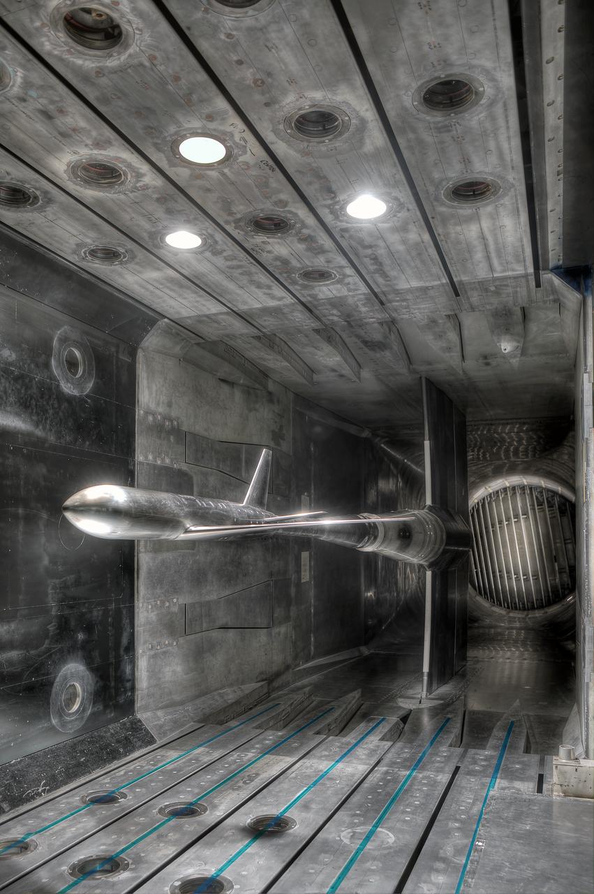
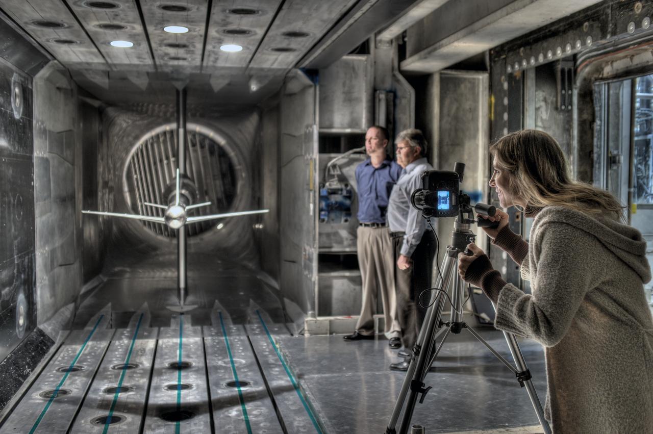
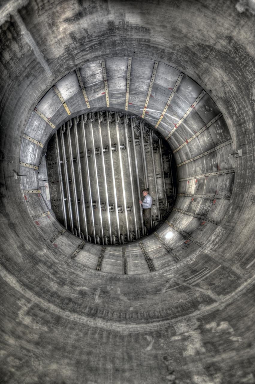
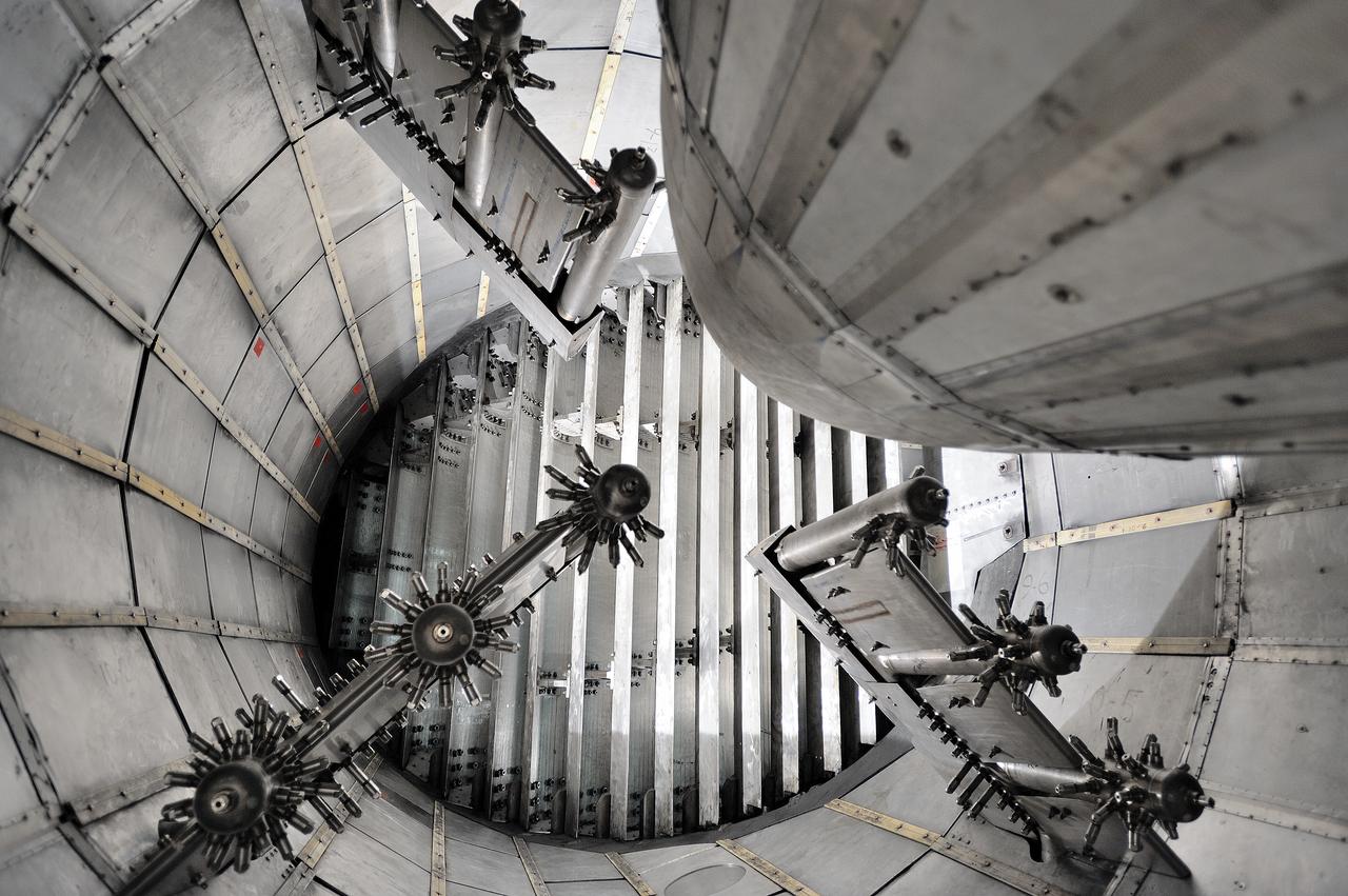
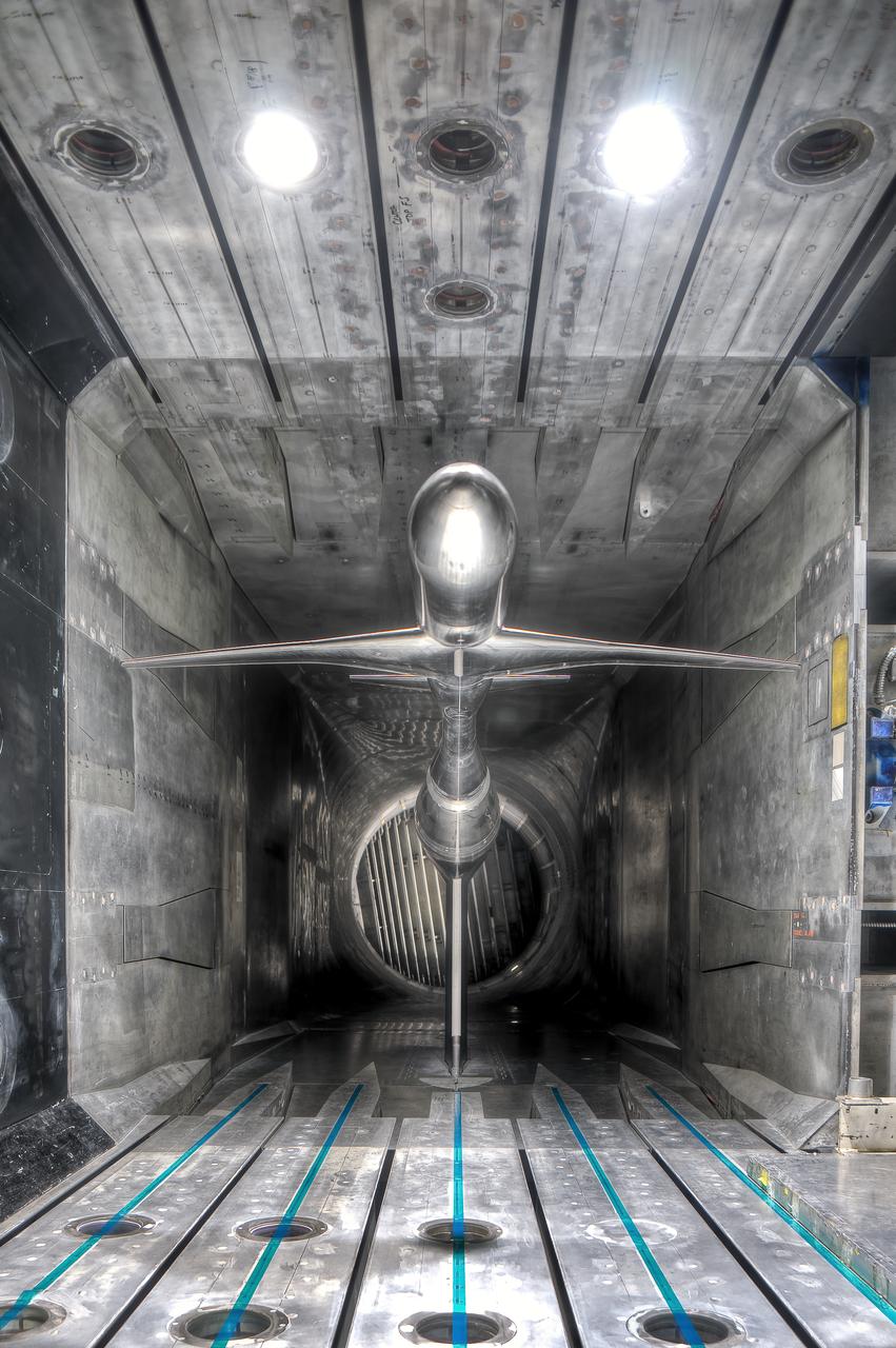
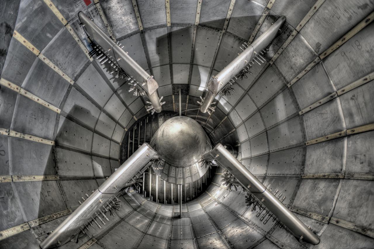
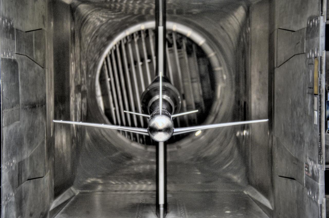
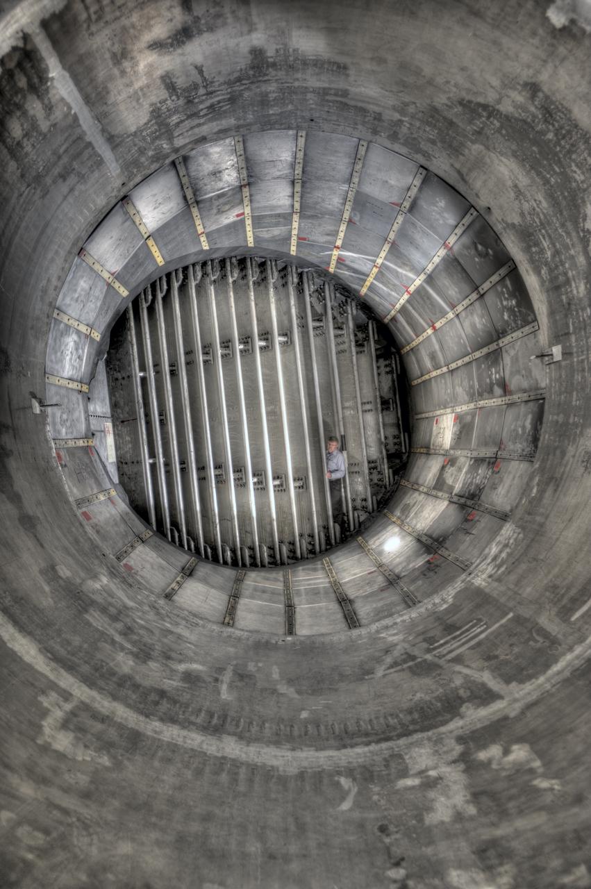
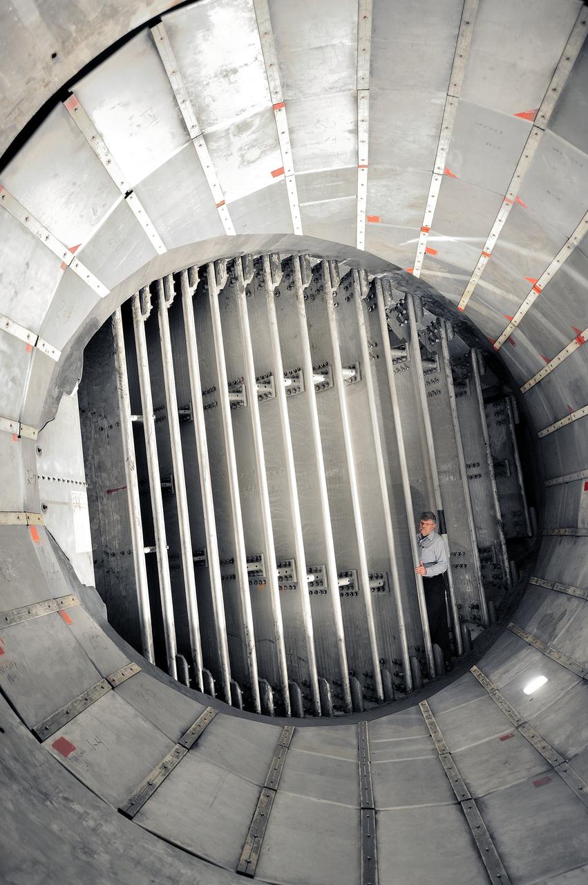
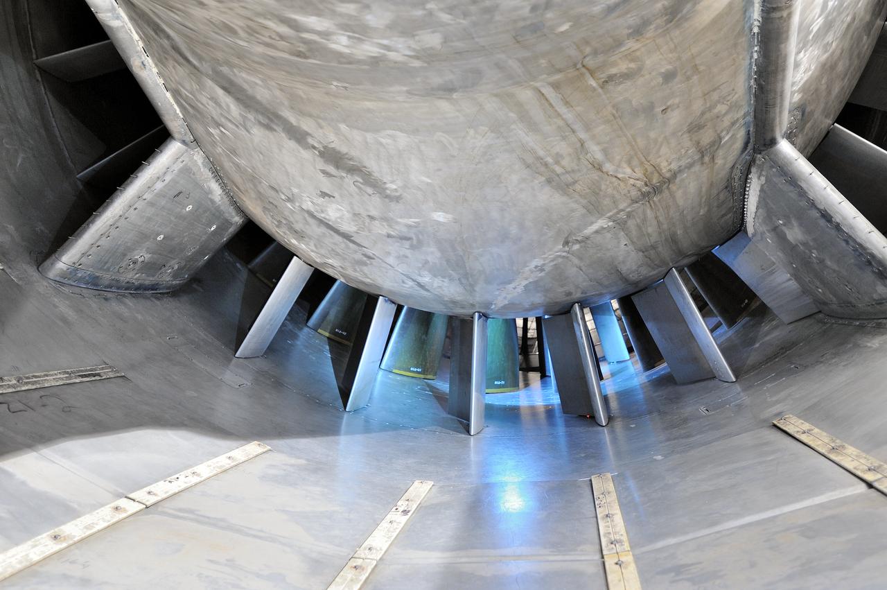
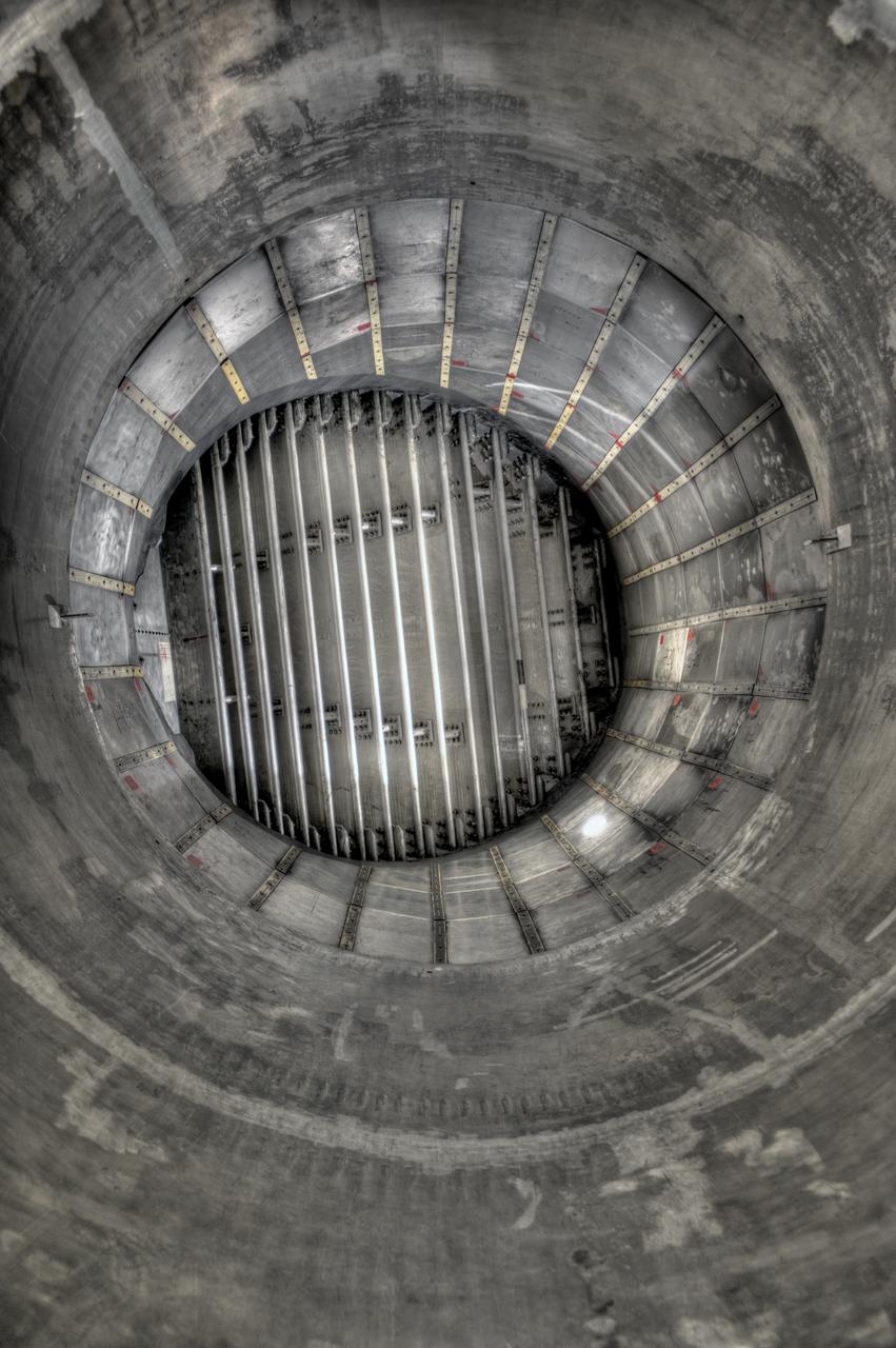
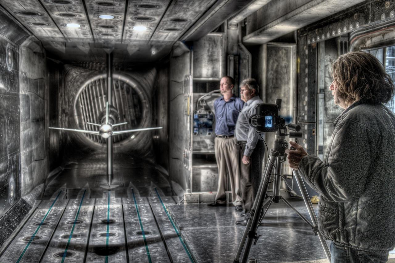
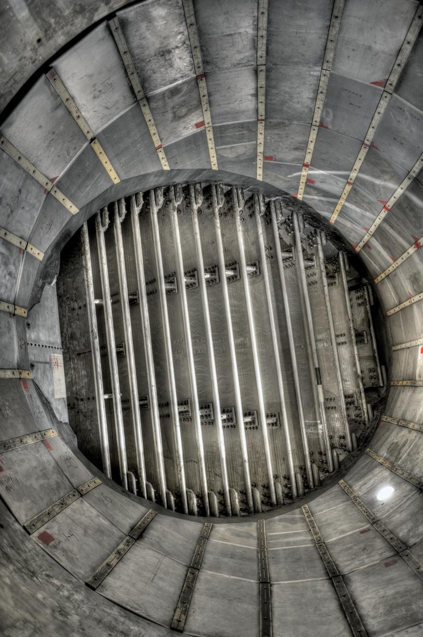
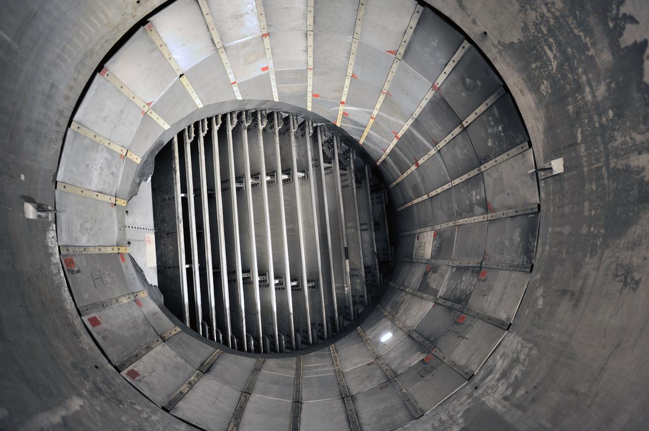
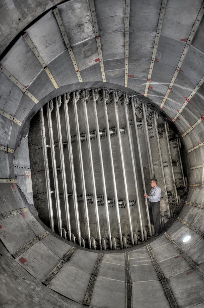
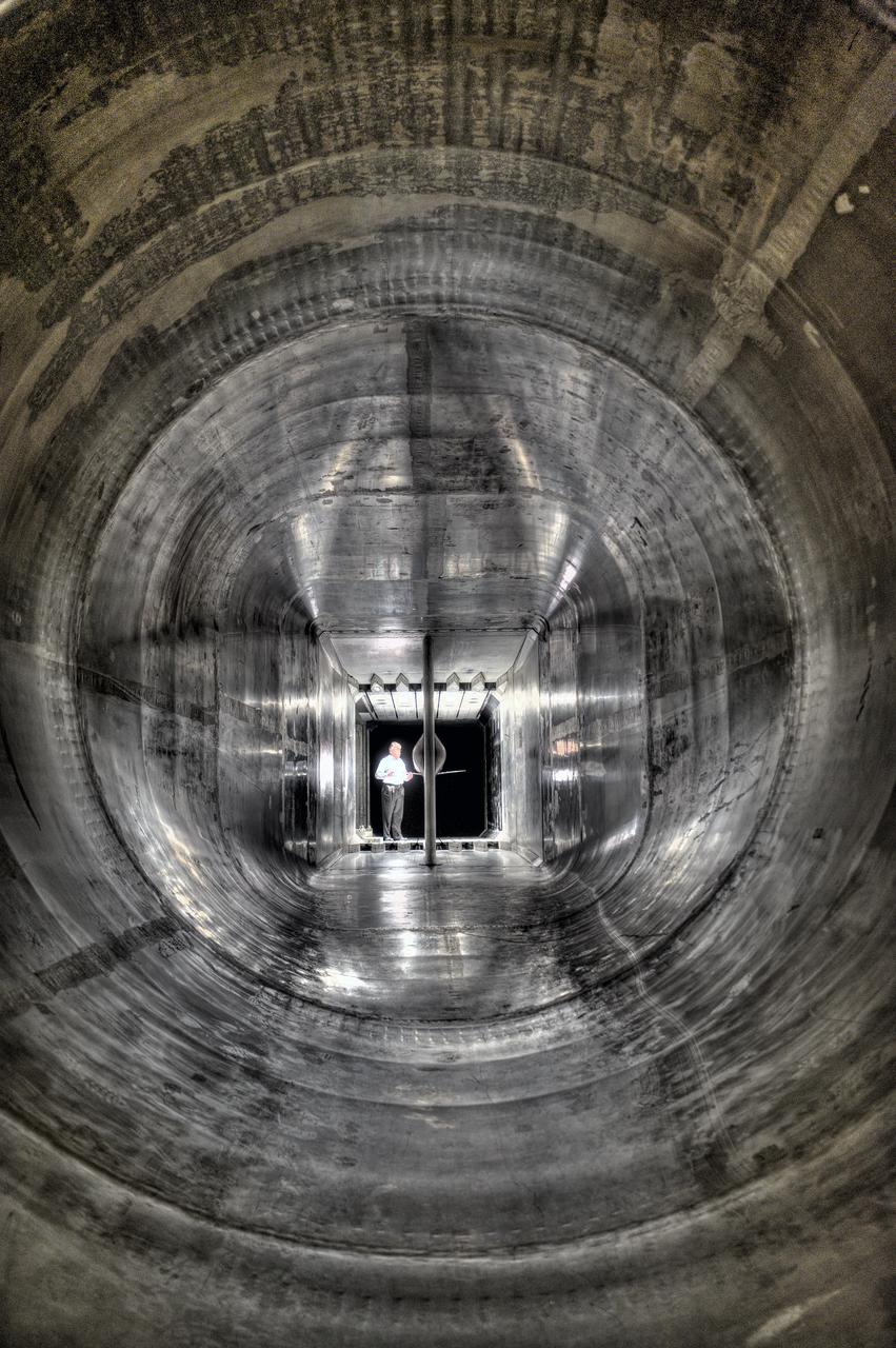
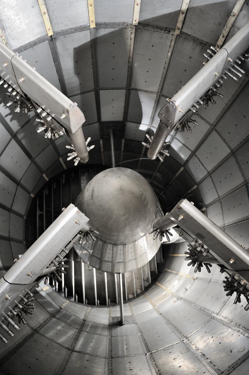
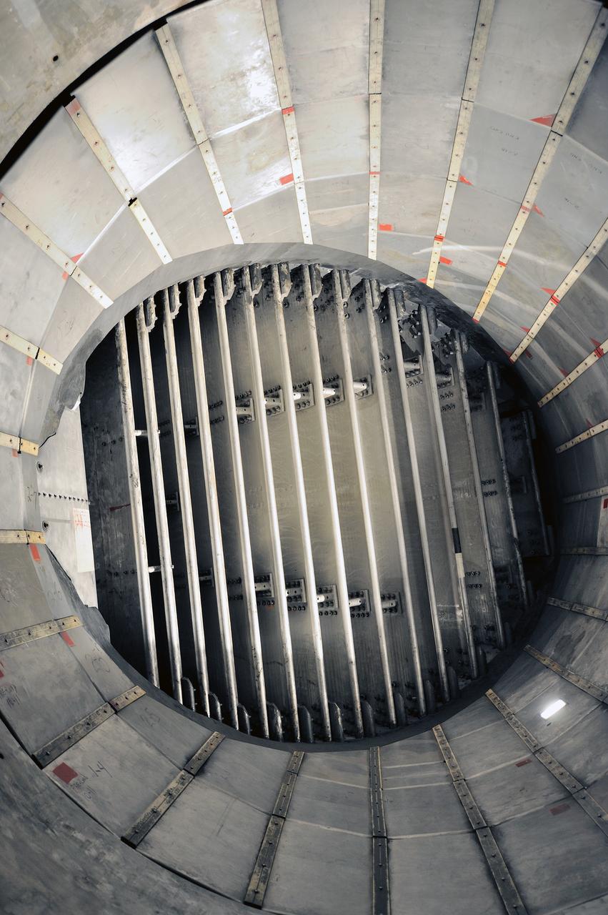
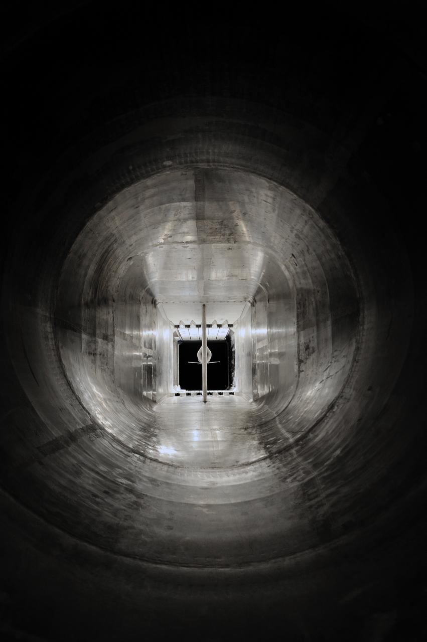
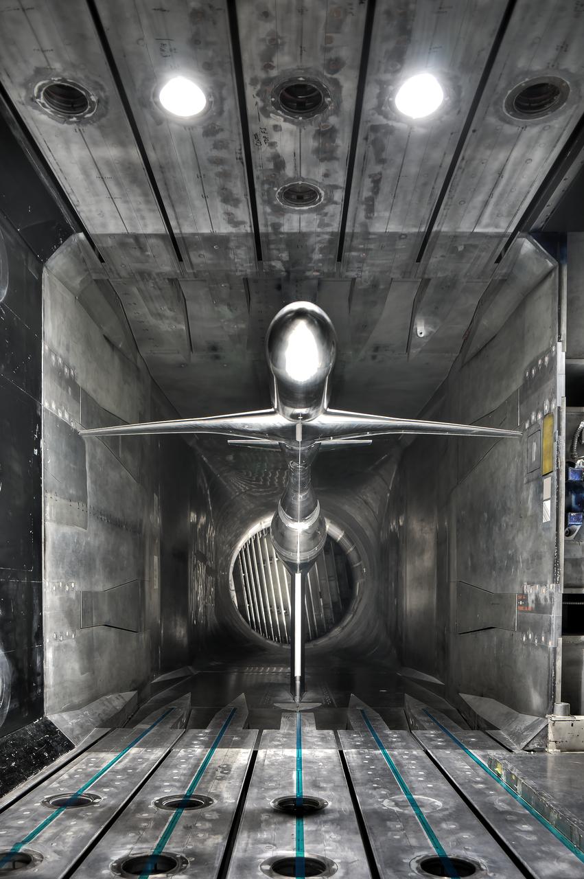
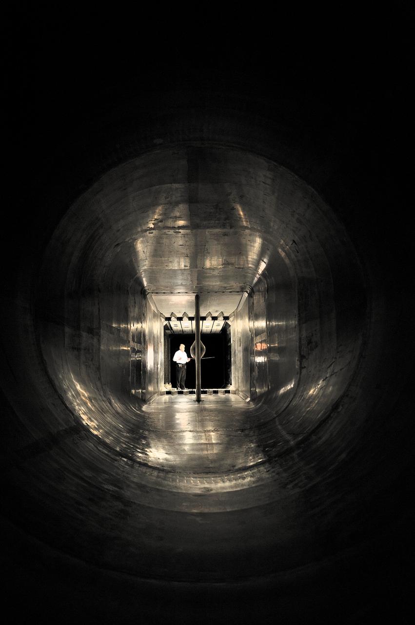
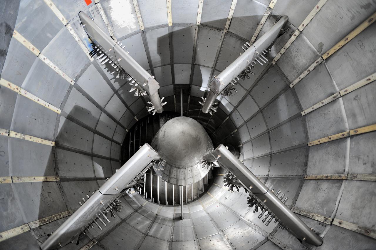
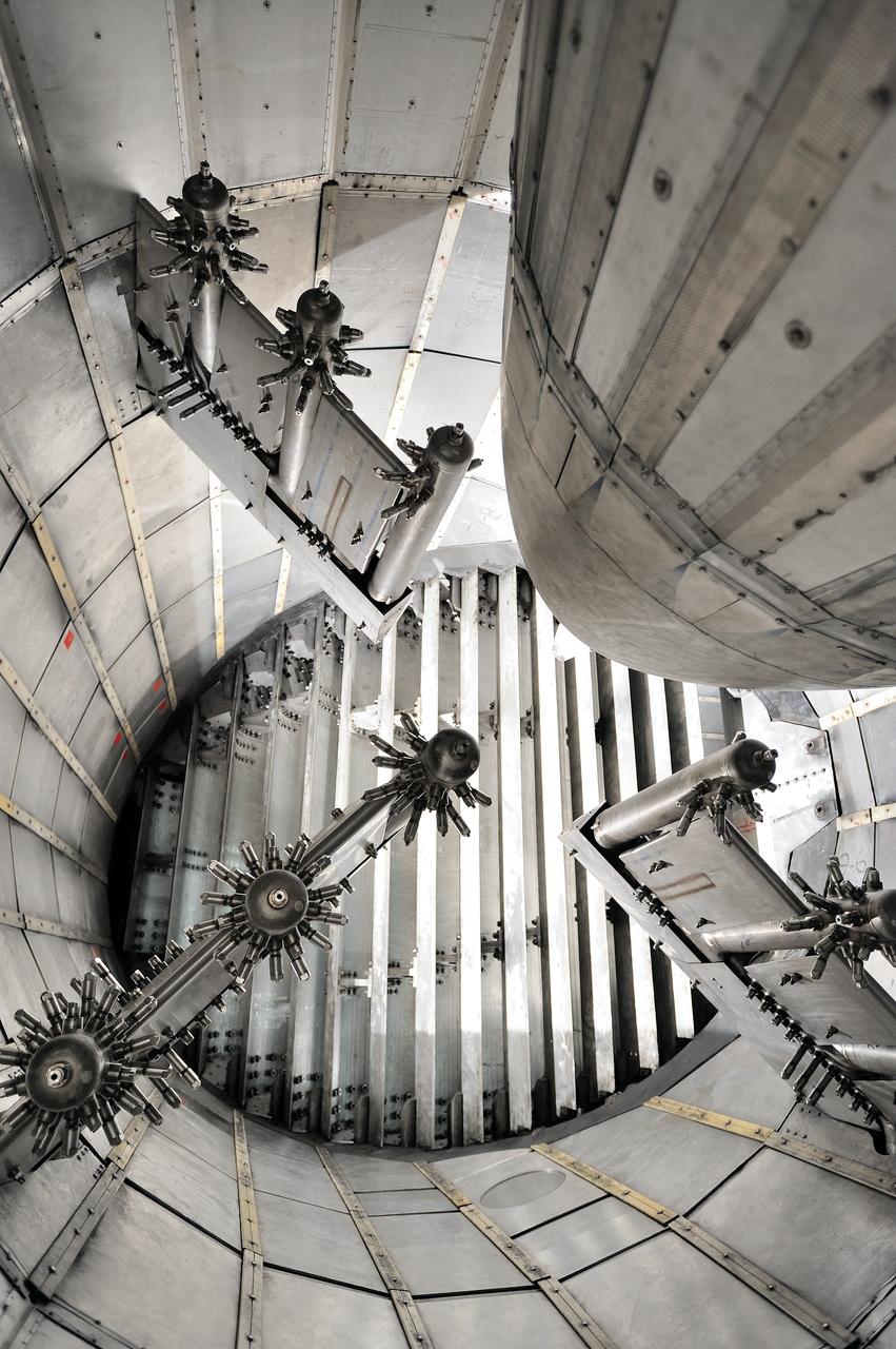
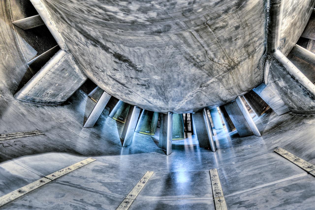
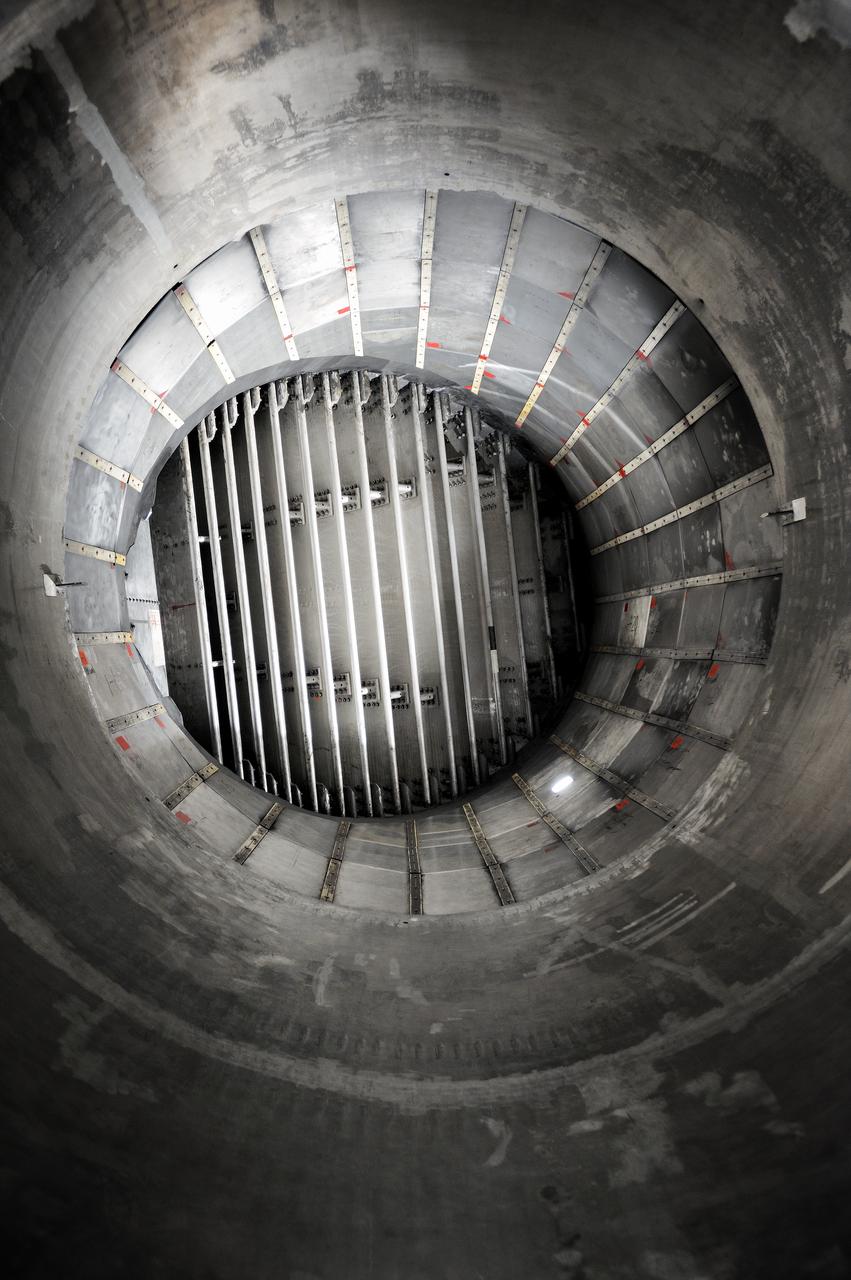
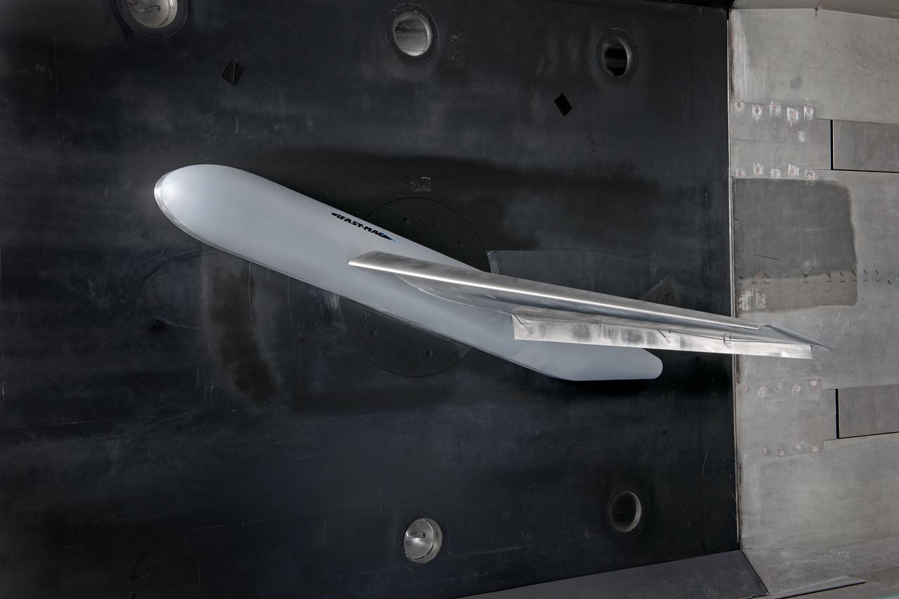
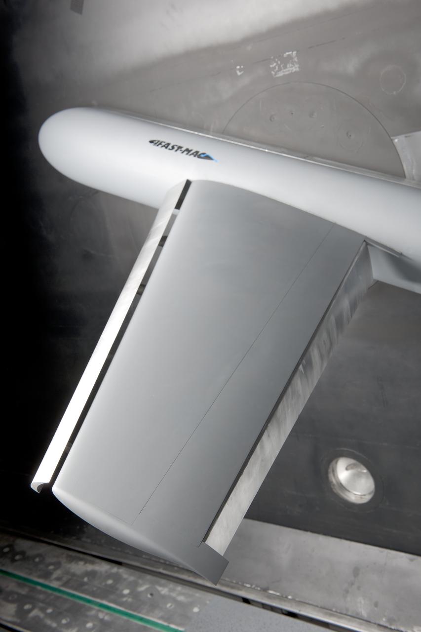
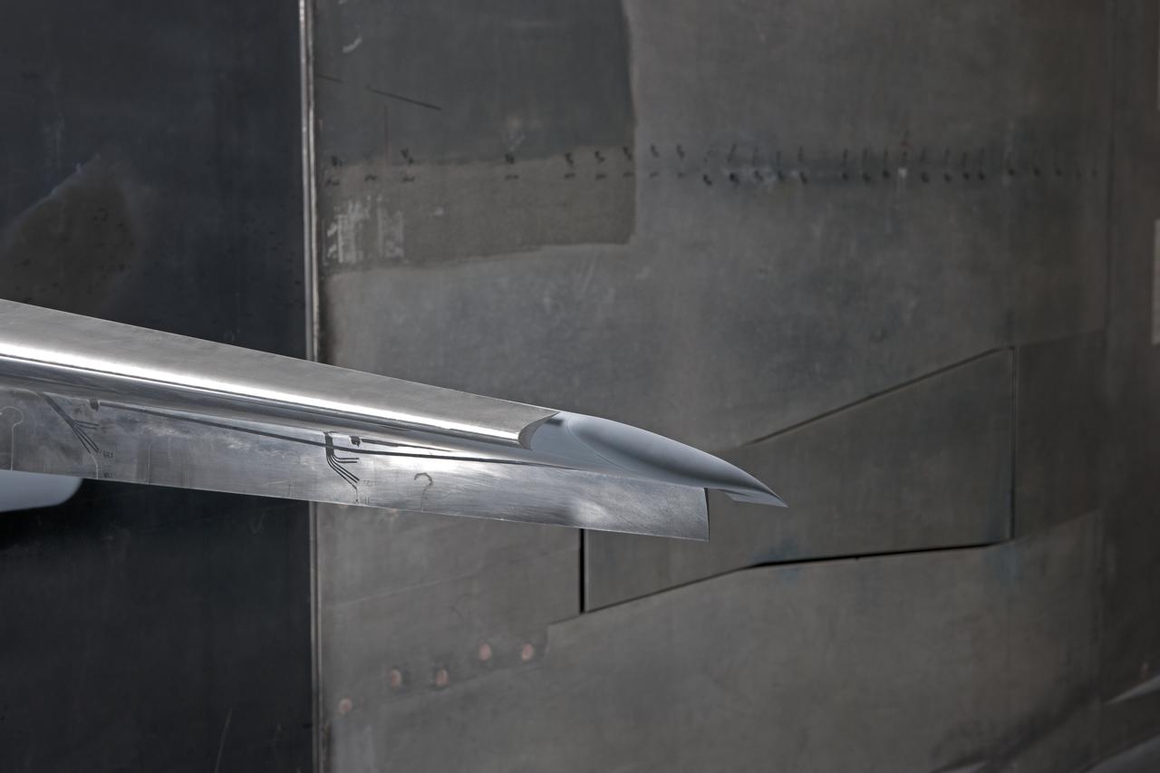
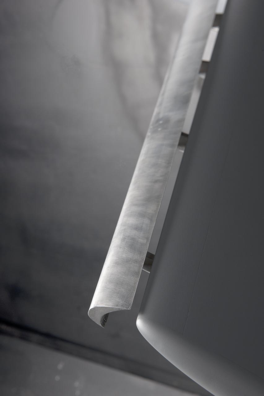
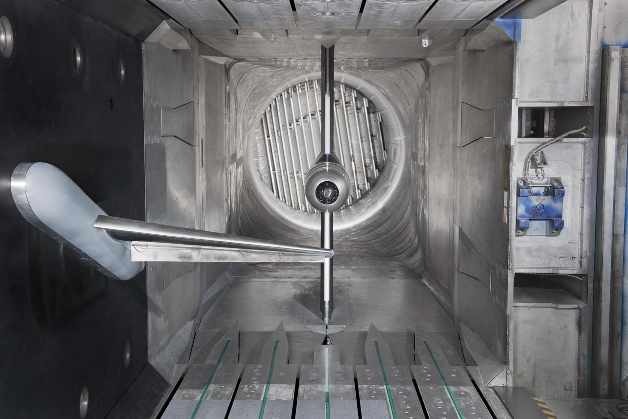
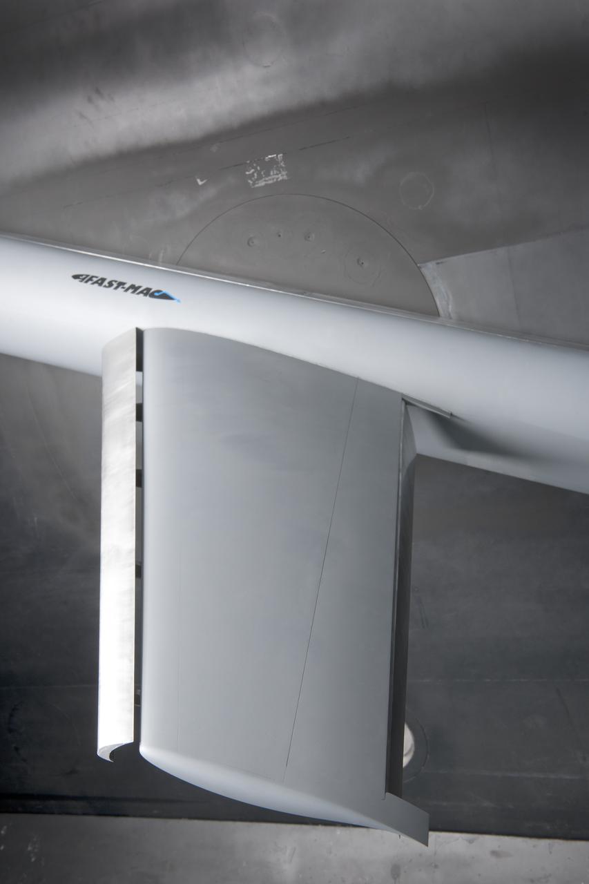
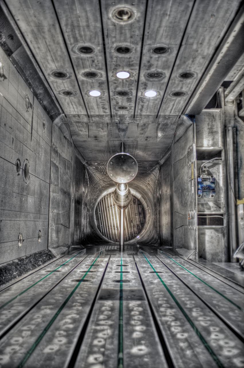
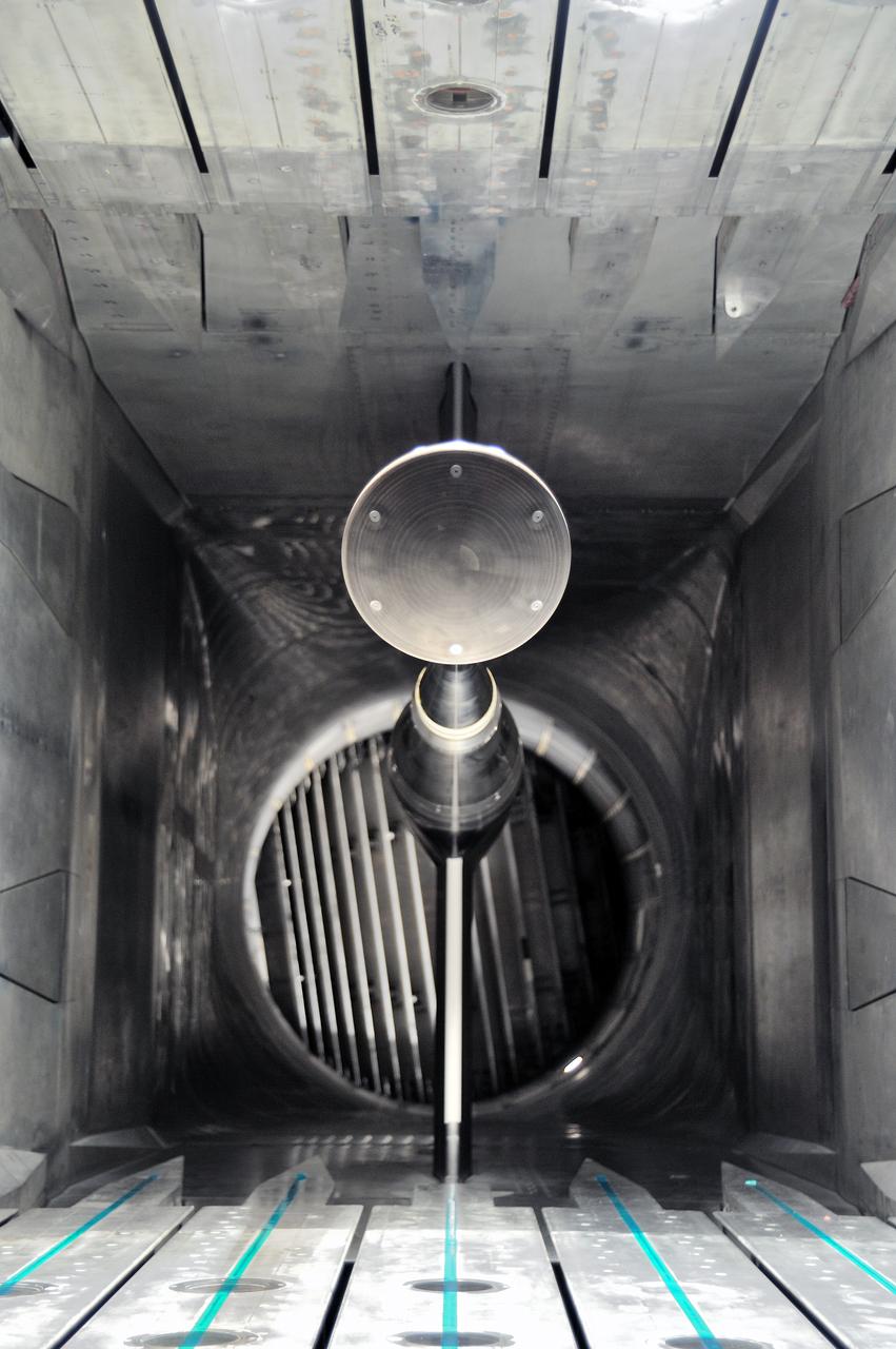
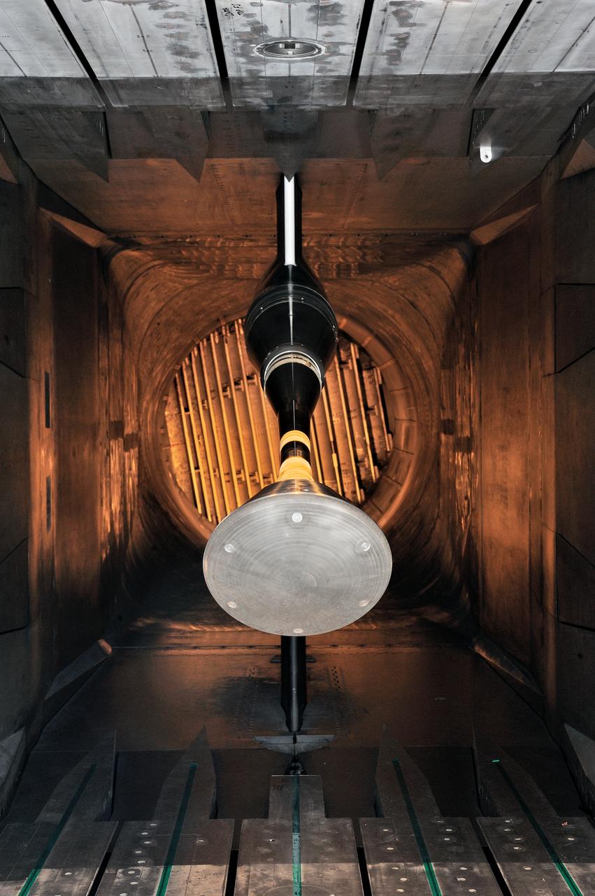
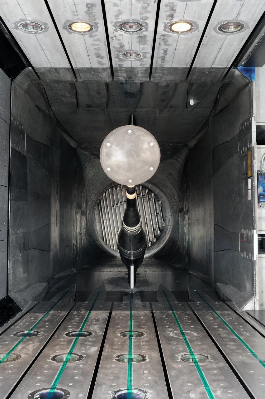
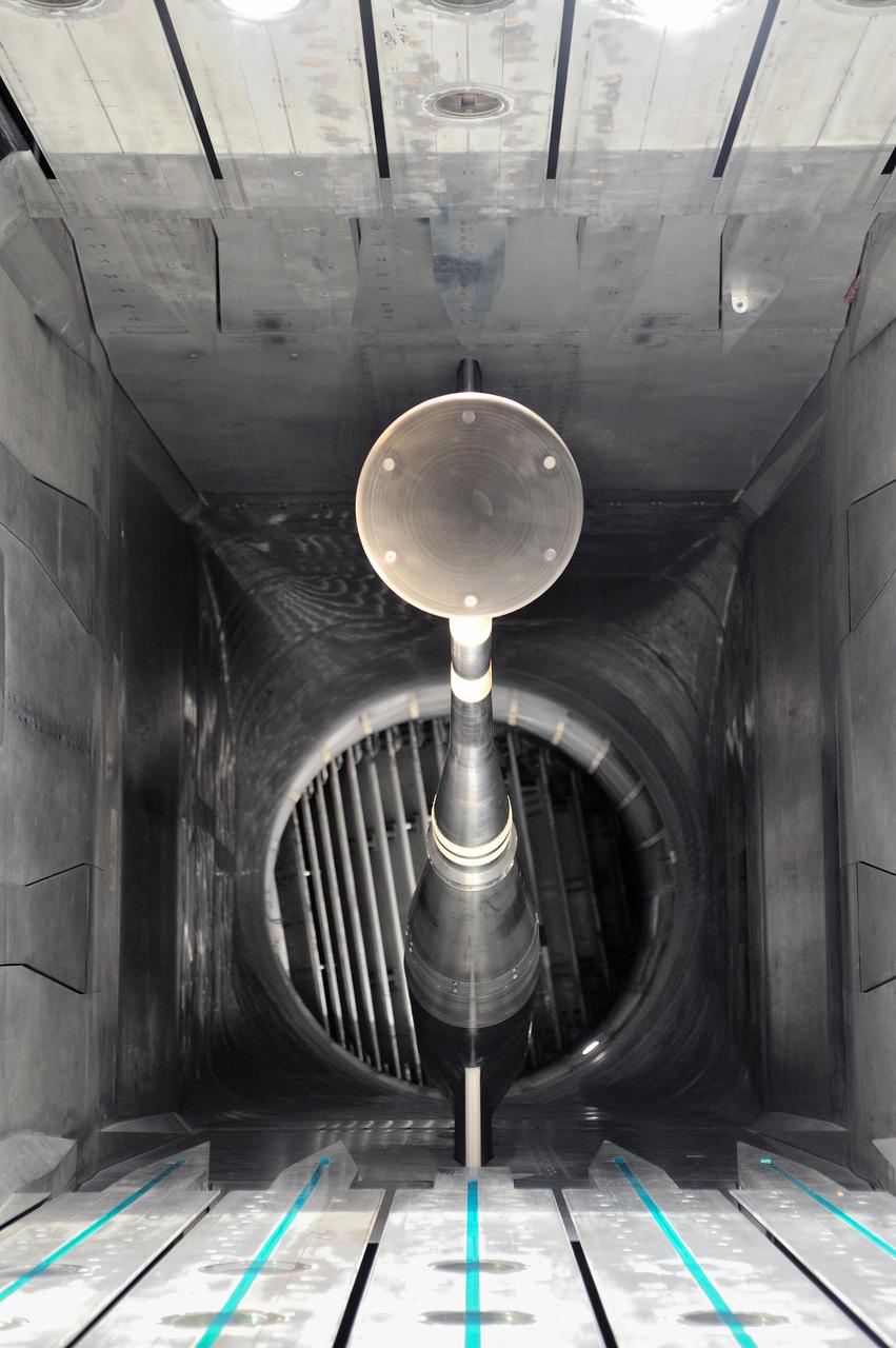
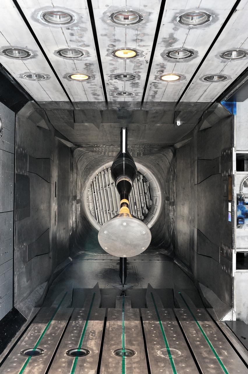
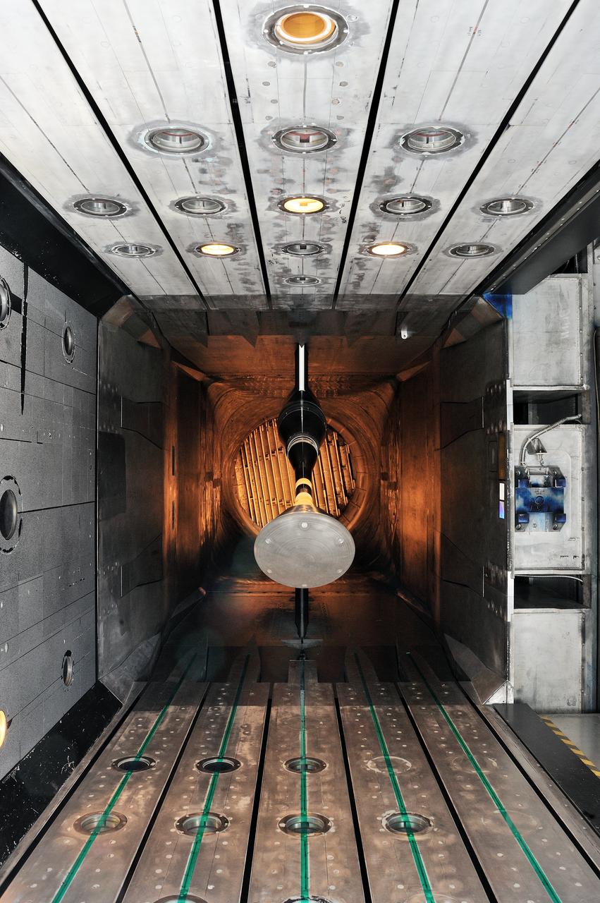
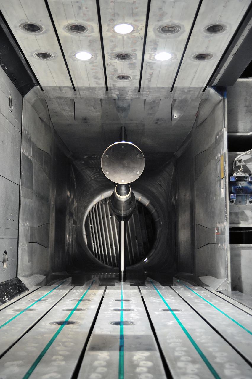
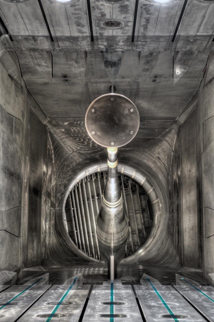
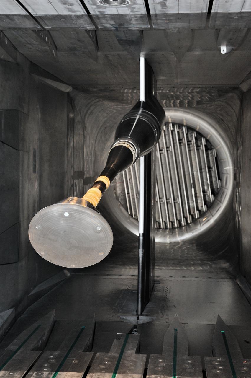
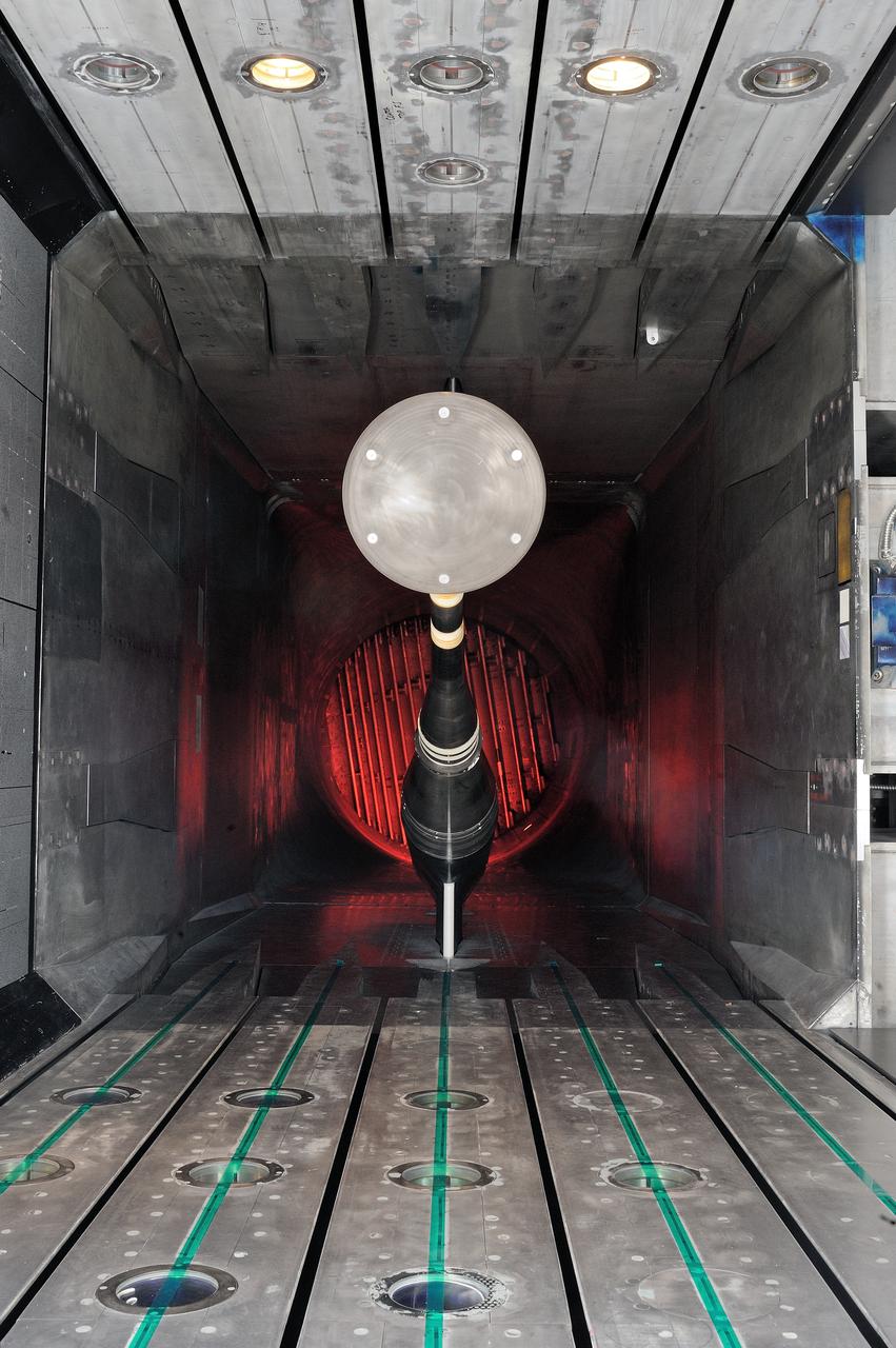
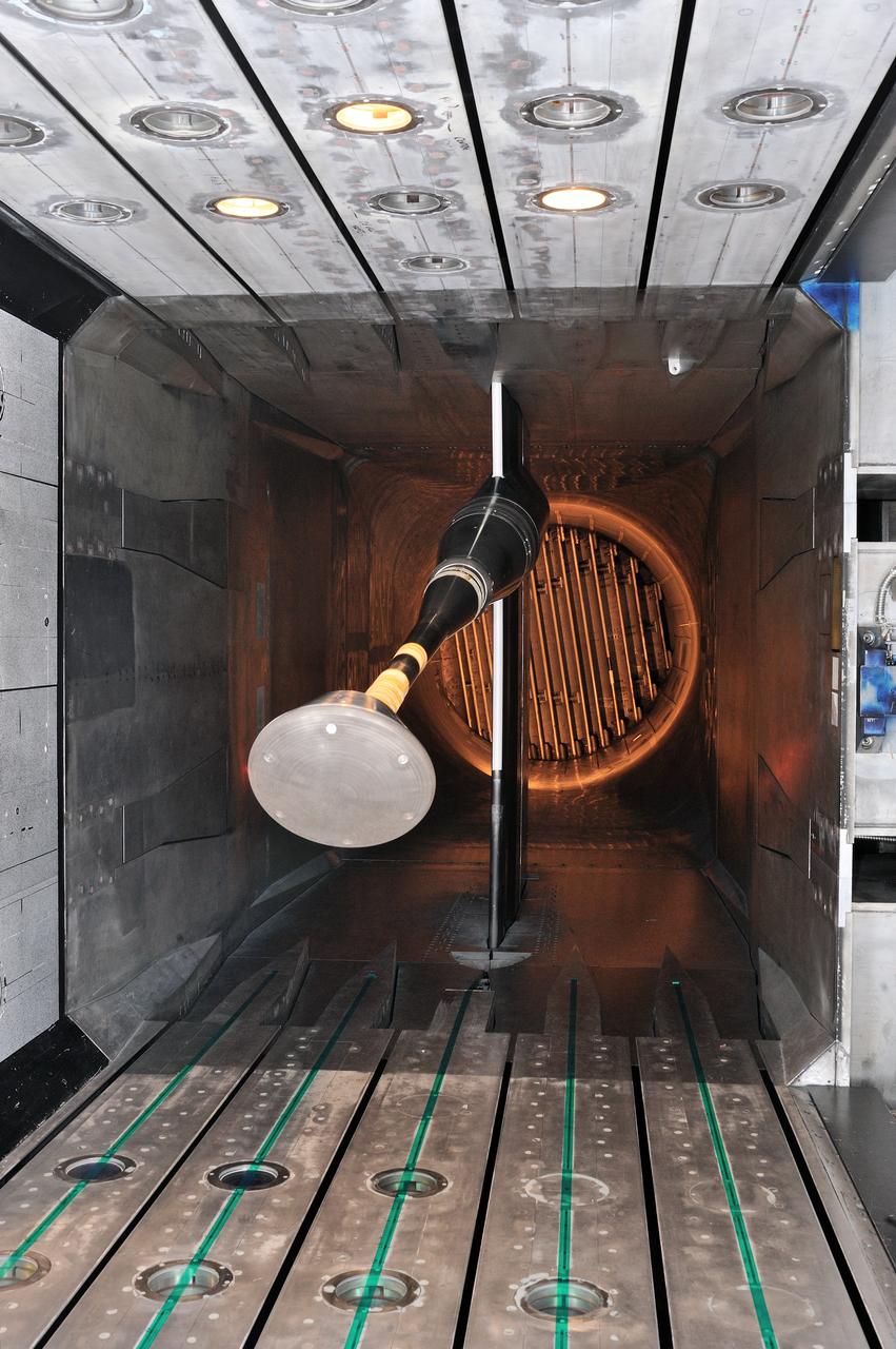
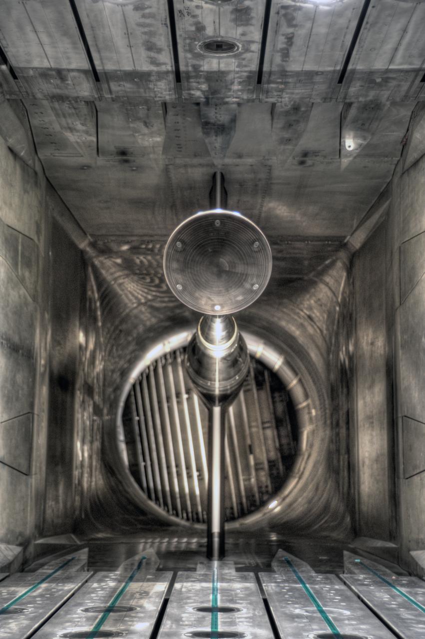
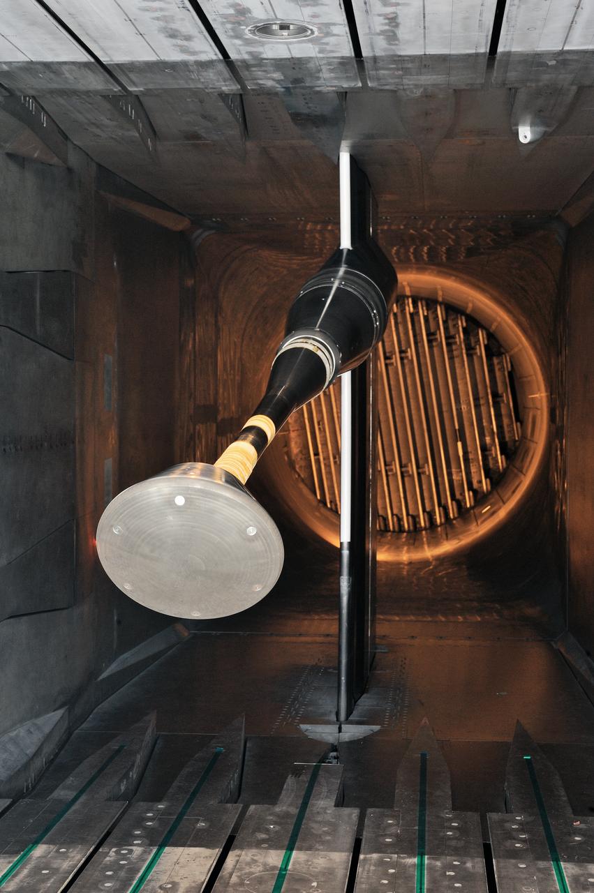
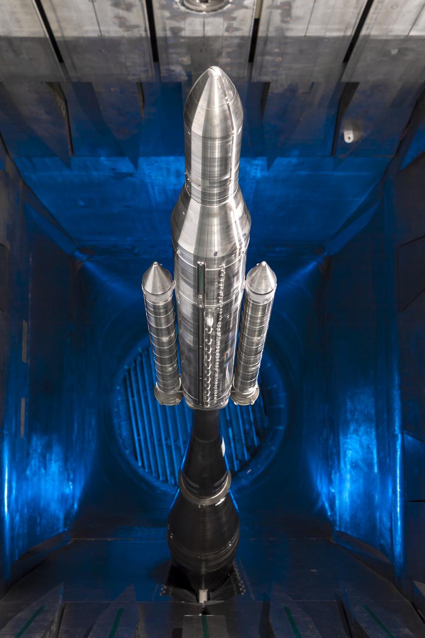
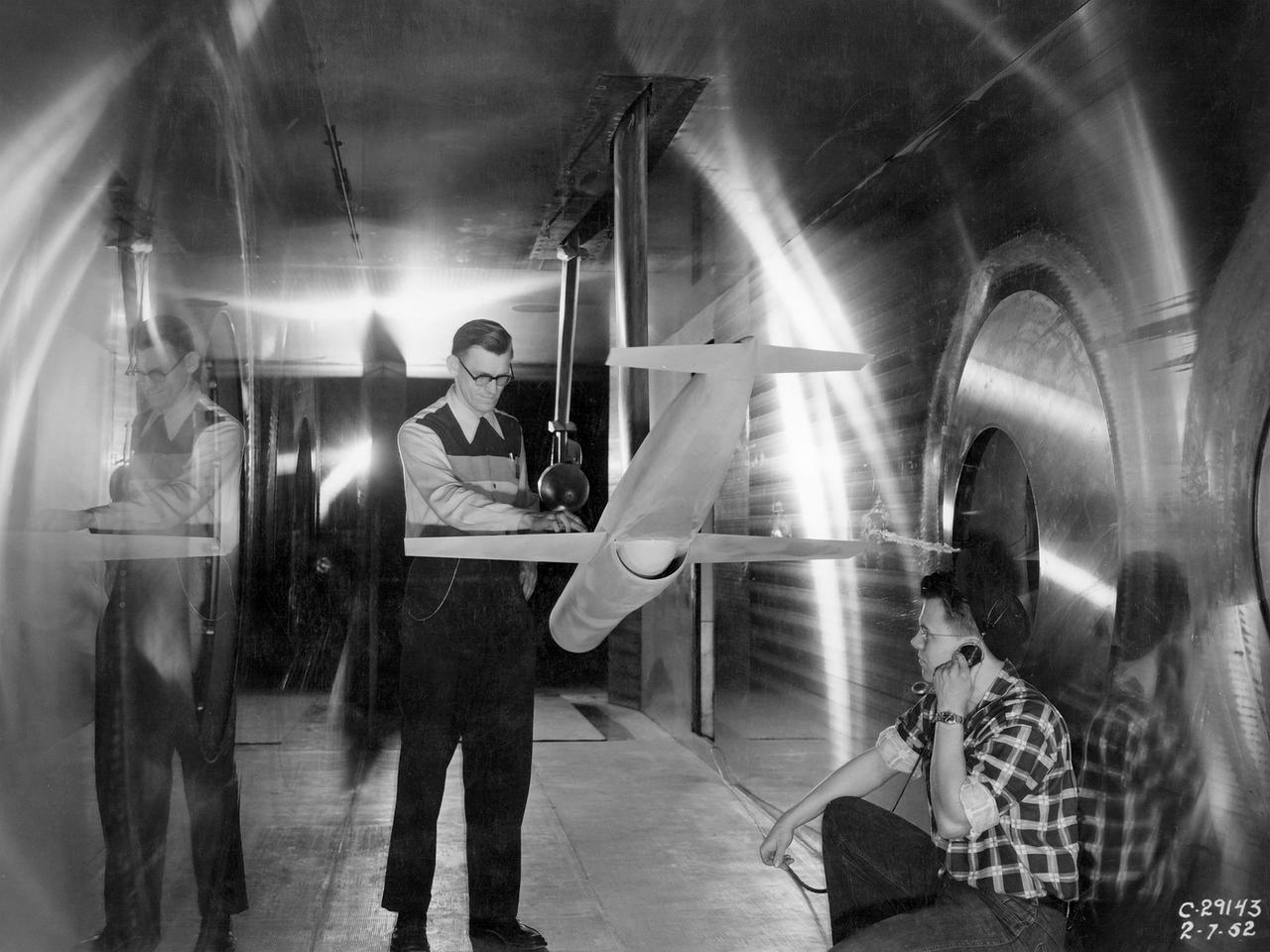
Ramjet Model and Technicians in the 8- by 6-Foot Supersonic Wind Tunnel