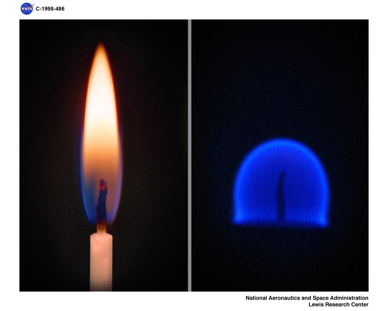
CANDLE FLAME NORMAL 1-G ONE GRAVITY AND MICROGRAVITY 0-G ZERO GRAVITY COMPARISON

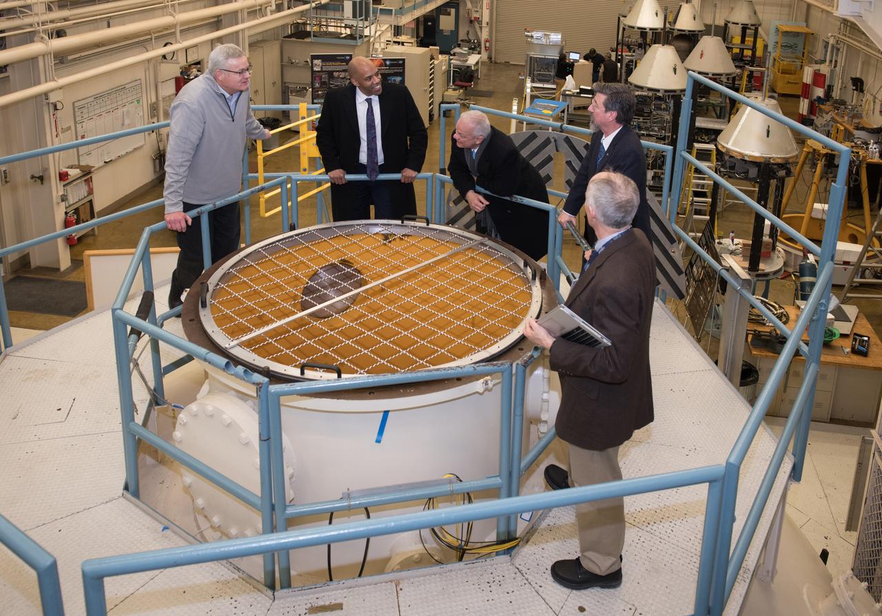
Zero Gravity Locomotion Simulator (ZLS) (0-g)
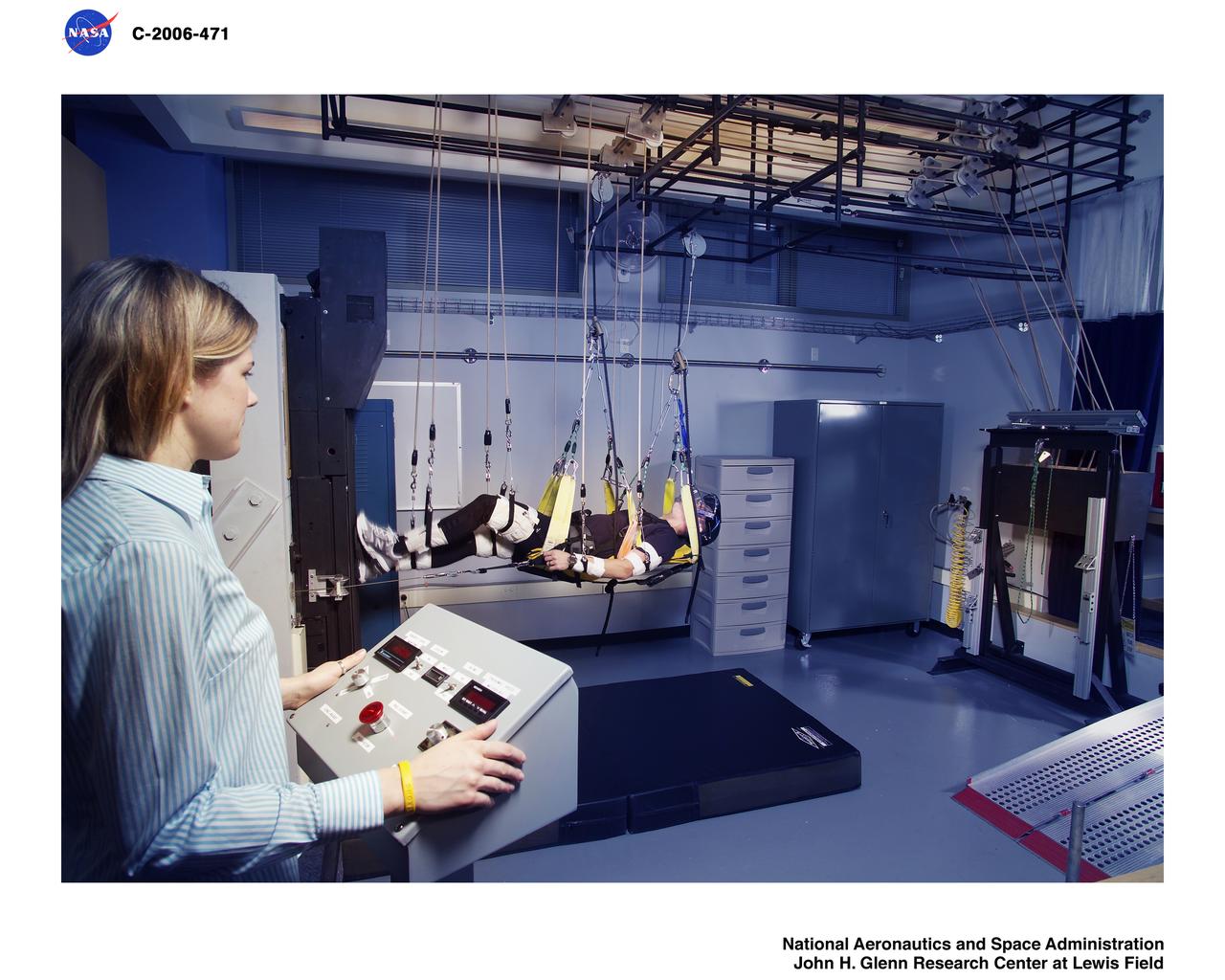
Zero Gravity Locomotion Simulator (ZLS) (0-g)
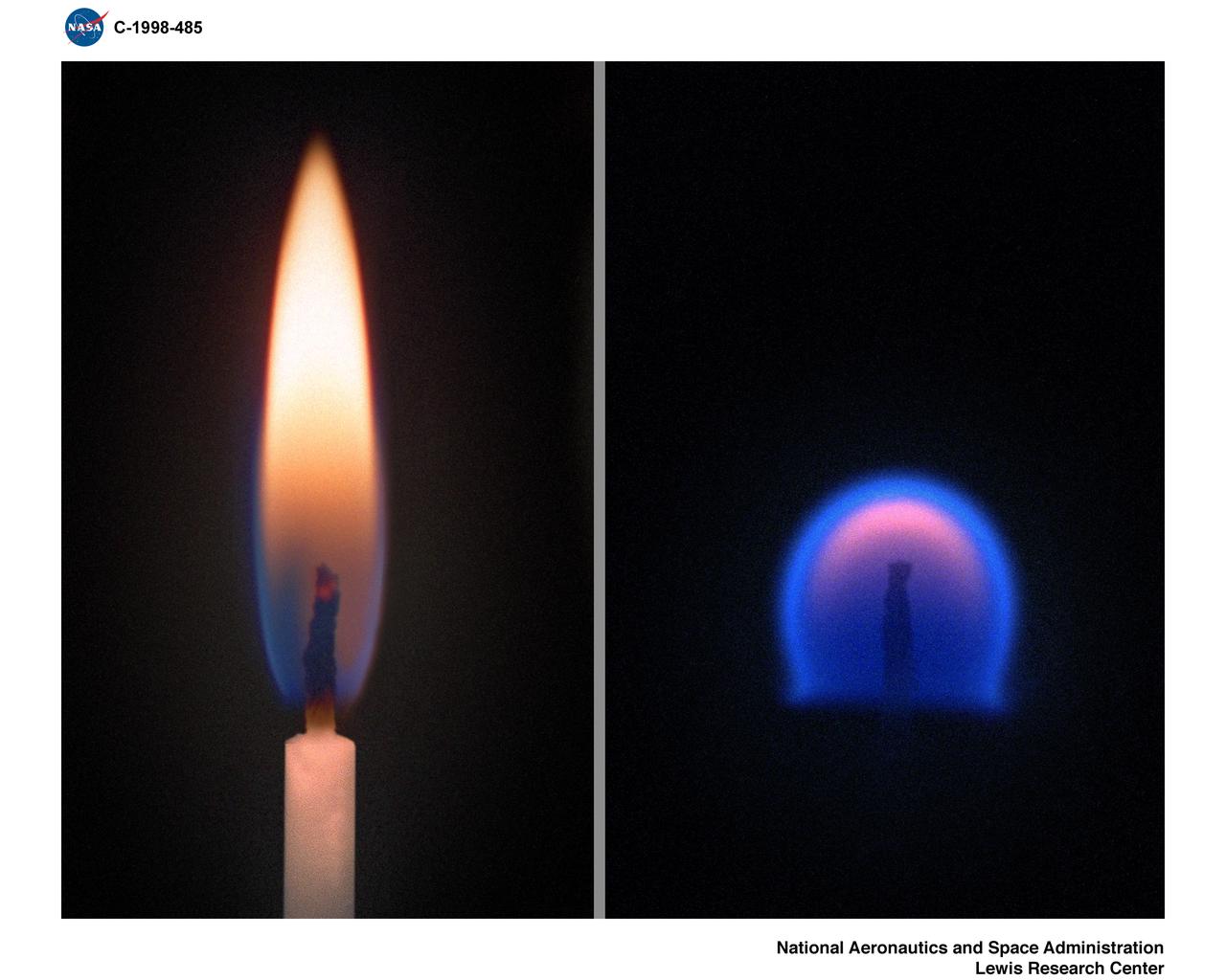
Comparison of a Candle Flame burning in normal gravity or 1-G (left) and a flame burning in Microgravity.
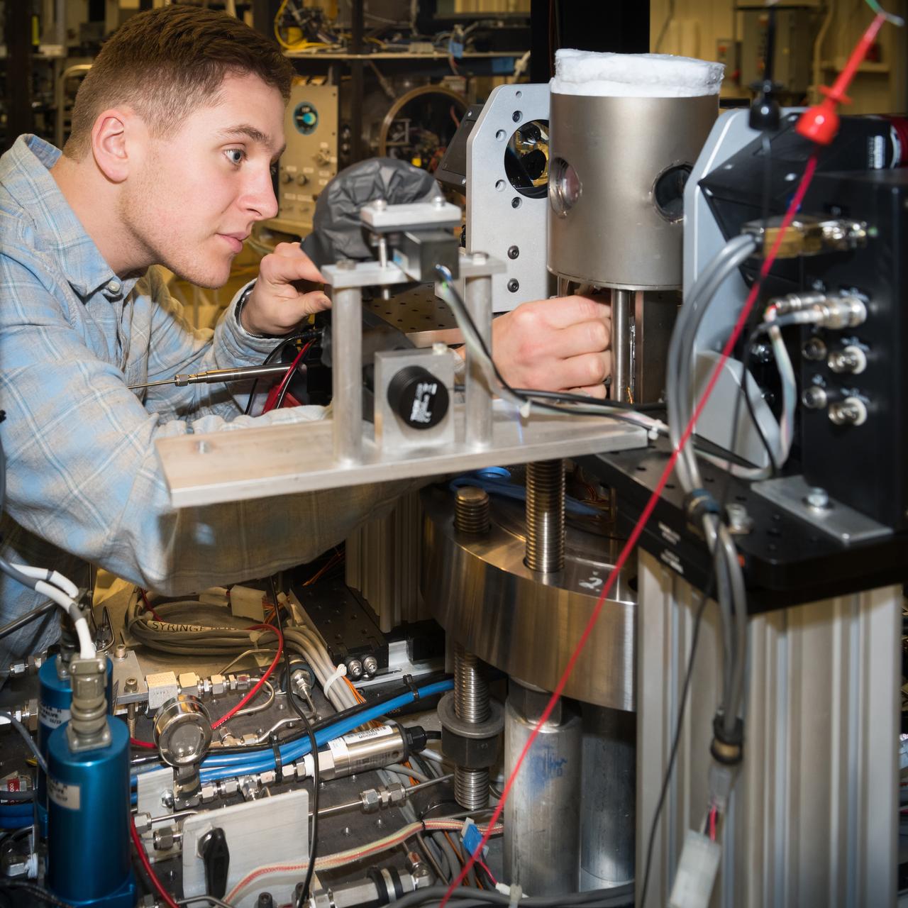
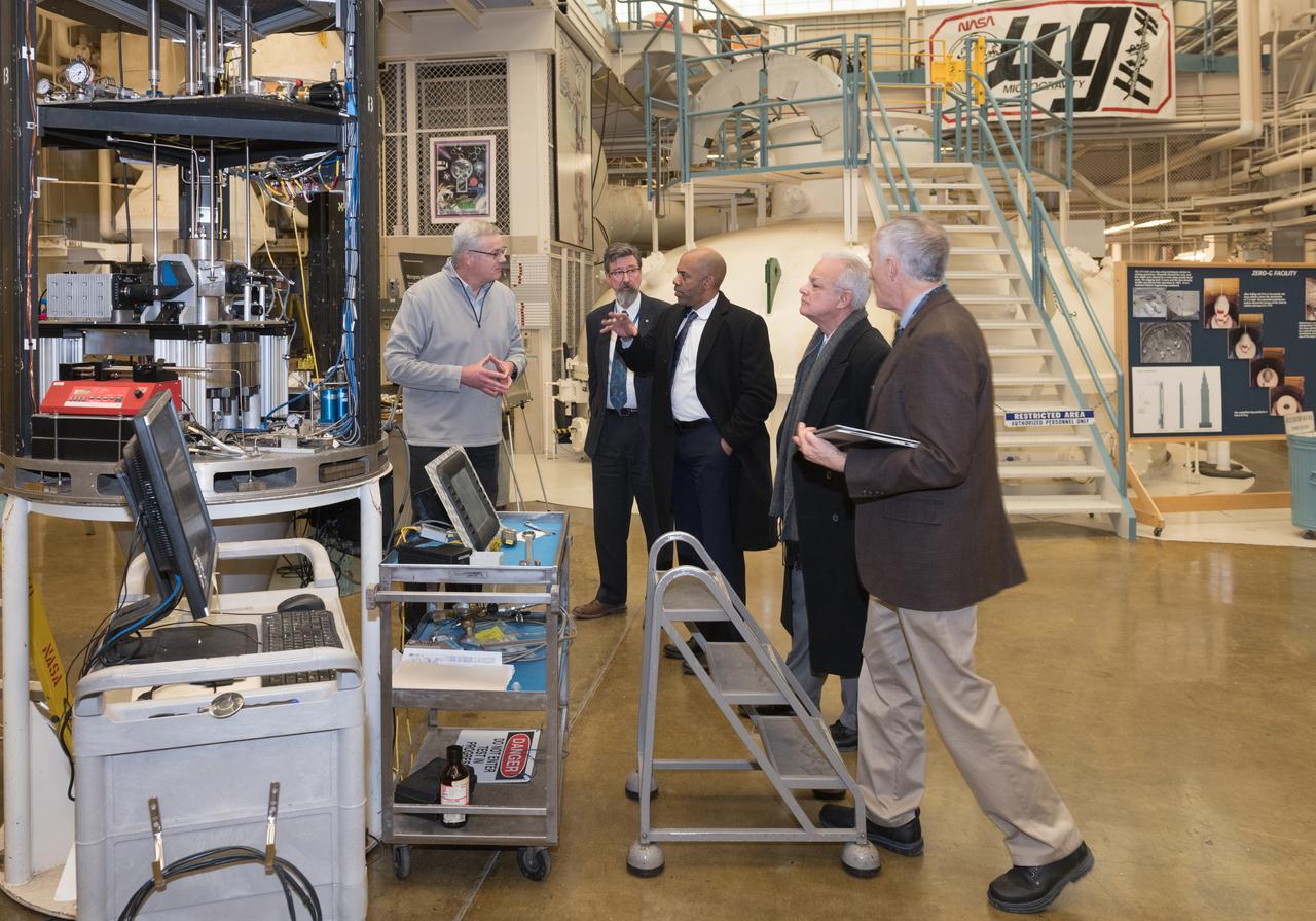
High Pressure Microgravity Combustion Experiment, HPMC, subjects liquid fuel droplets to high pressures and temperatures to study the ignition process in engine conditions, with a goal of improving fuel efficiency. In this configuration, the experiment is capable of testing droplet combustion at up to 100 atm of pressure, testing the droplet deployment system, which inserts the fuel droplet into the experiment.
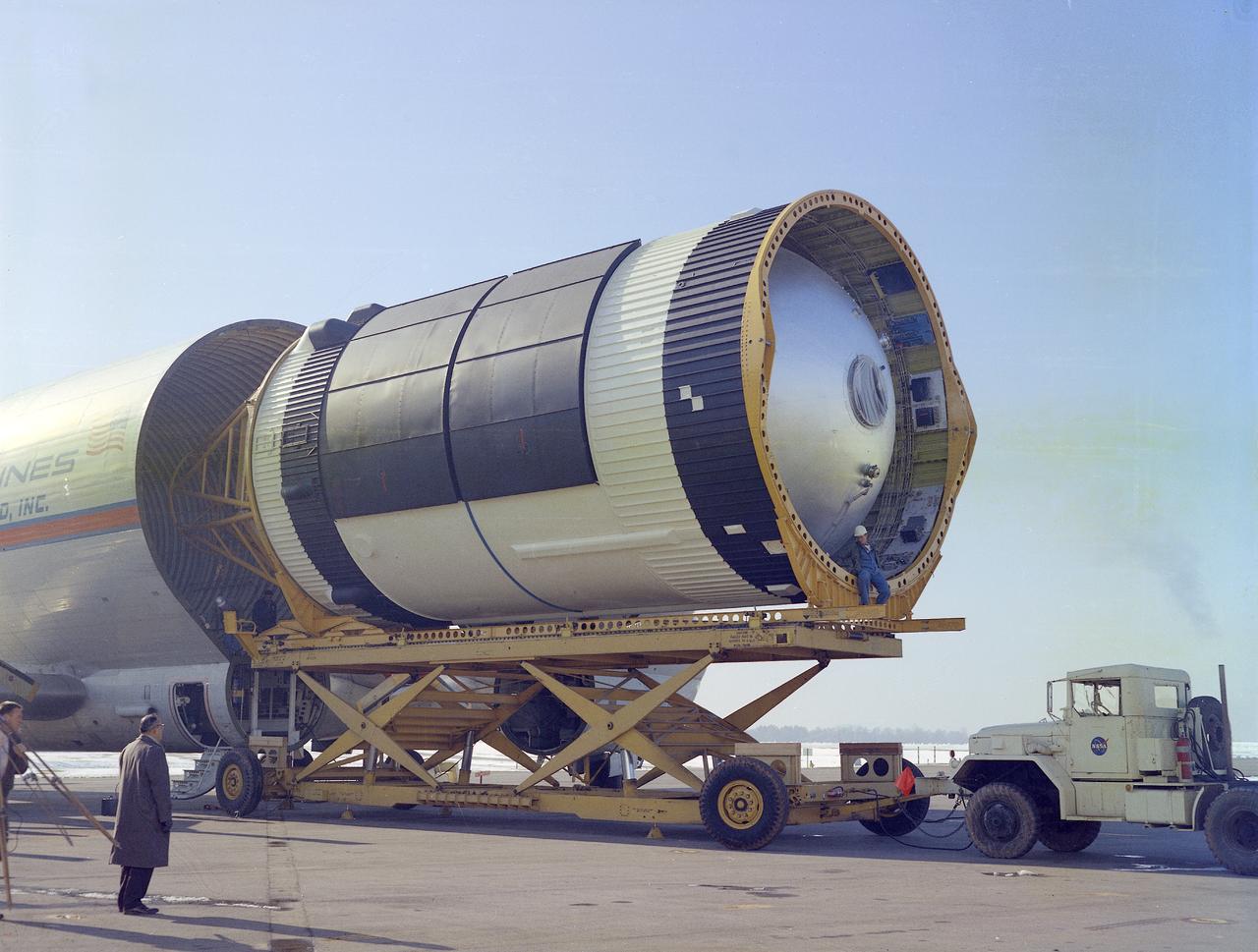
This photograph was taken at the Redstone airfield, Huntsville, Alabama, during the unloading of the Saturn V S-IVB stage that housed the Orbital Workshop (OWS) from the Super Guppy, the NASA plane that was specially built to carry oversized cargo. The OWS measured 22 feet (6.7 m) in diameter, and 48 feet (14.6 m) in length. The Saturn V S-IVB stage was modified at the McDornell Douglas facility at Huntington Beach, California, for a new role, which was to house the OWS. In addition to the test articles, engineering mockups, and flight equipment, both McDonnell Douglas and Martin Marietta built 0-G trainers, neutral buoyancy trainers, and high-fidelity mockups for the 1-G trainer to be used in the KC-135 aircraft. The Marshall Space Flight Center had program management responsibility for the development of Skylab hardware and experiments.

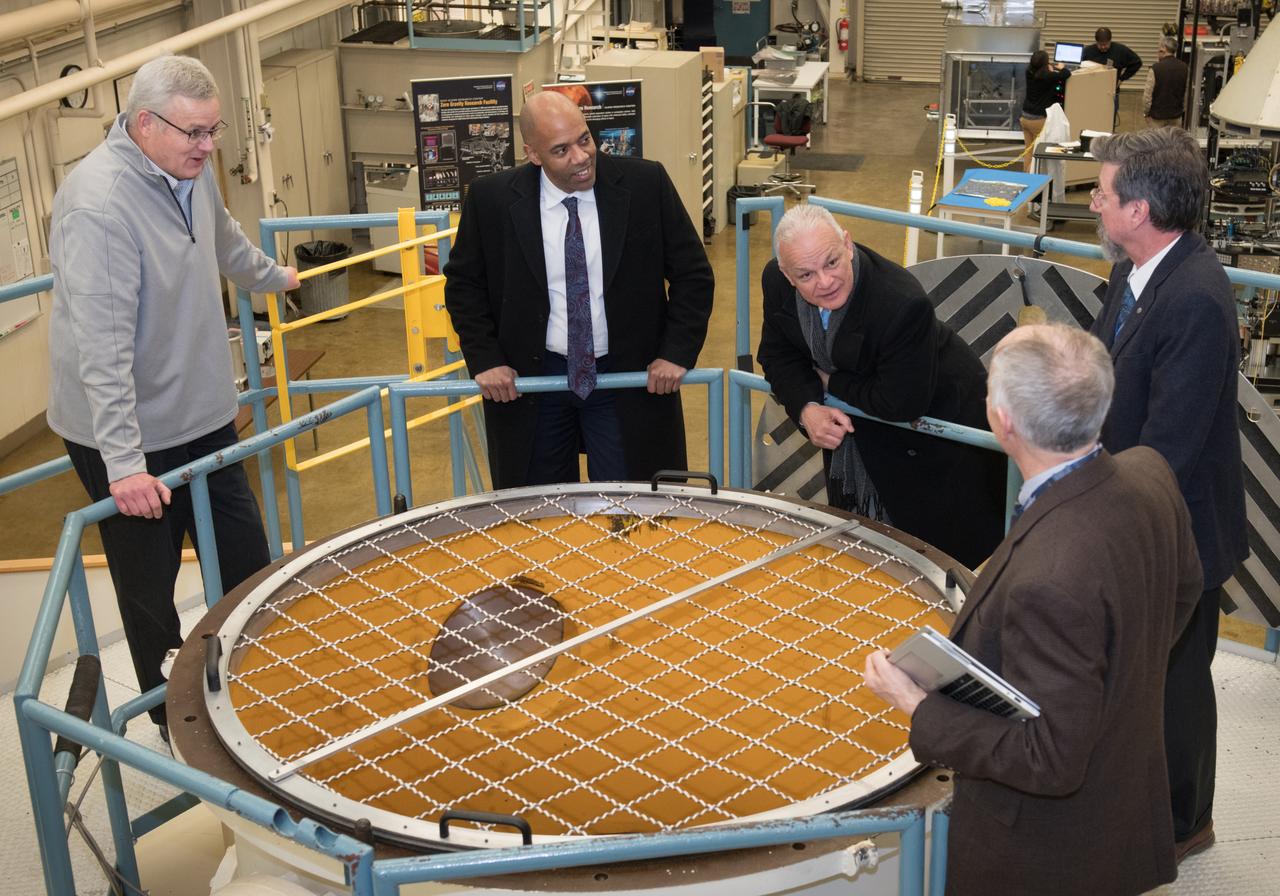
Office of the Chief Technologist, OCT Innovation Workshop, and Facility Tours
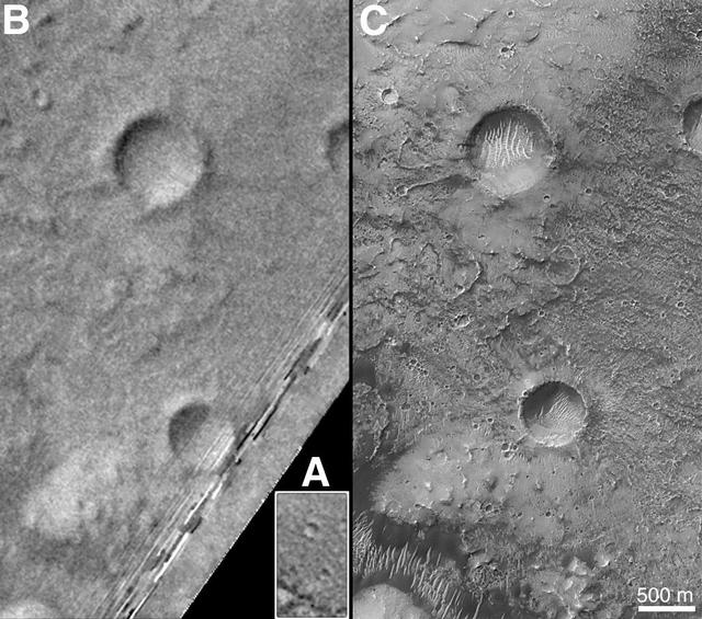
On Earth, the longitude of the Royal Observatory in Greenwich, England is defined as the "prime meridian," or the zero point of longitude. Locations on Earth are measured in degrees east or west from this position. The prime meridian was defined by international agreement in 1884 as the position of the large "transit circle," a telescope in the Observatory's Meridian Building. The transit circle was built by Sir George Biddell Airy, the 7th Astronomer Royal, in 1850. (While visual observations with transits were the basis of navigation until the space age, it is interesting to note that the current definition of the prime meridian is in reference to orbiting satellites and Very Long Baseline Interferometry (VLBI) measurements of distant radio sources such as quasars. This "International Reference Meridian" is now about 100 meters east of the Airy Transit at Greenwich.) For Mars, the prime meridian was first defined by the German astronomers W. Beer and J. H. Mädler in 1830-32. They used a small circular feature, which they designated "a," as a reference point to determine the rotation period of the planet. The Italian astronomer G. V. Schiaparelli, in his 1877 map of Mars, used this feature as the zero point of longitude. It was subsequently named Sinus Meridiani ("Middle Bay") by Camille Flammarion. When Mariner 9 mapped the planet at about 1 kilometer (0.62 mile) resolution in 1972, an extensive "control net" of locations was computed by Merton Davies of the RAND Corporation. Davies designated a 0.5-kilometer-wide crater (0.3 miles wide), subsequently named "Airy-0" (within the large crater Airy in Sinus Meridiani) as the longitude zero point. (Airy, of course, was named to commemorate the builder of the Greenwich transit.) This crater was imaged once by Mariner 9 (the 3rd picture taken on its 533rd orbit, 533B03) and once by the Viking 1 orbiter in 1978 (the 46th image on that spacecraft's 746th orbit, 746A46), and these two images were the basis of the martian longitude system for the rest of the 20th Century. The Mars Global Surveyor (MGS) Mars Orbiter Camera (MOC) has attempted to take a picture of Airy-0 on every close overflight since the beginning of the MGS mapping mission. It is a measure of the difficulty of hitting such a small target that nine attempts were required, since the spacecraft did not pass directly over Airy-0 until almost the end of the MGS primary mission, on orbit 8280 (January 13, 2001). In the left figure above, the outlines of the Mariner 9, Viking, and Mars Global Surveyor images are shown on a MOC wide angle context image, M23-00924. In the right figure, sections of each of the three images showing the crater Airy-0 are presented. A is a piece of the Mariner 9 image, B is from the Viking image, and C is from the MGS image. Airy-0 is the larger crater toward the top-center in each frame. The MOC observations of Airy-0 not only provide a detailed geological close-up of this historic reference feature, they will be used to improve our knowledge of the locations of all features on Mars, which will in turn enable more precise landings on the Red Planet by future spacecraft and explorers. http://photojournal.jpl.nasa.gov/catalog/PIA03207
Office of the Chief Technologist, OCT Innovation Workshop, and Facility Tours
Office of the Chief Technologist, OCT Innovation Workshop, and Facility Tours
Office of the Chief Technologist, OCT Innovation Workshop, and Facility Tours