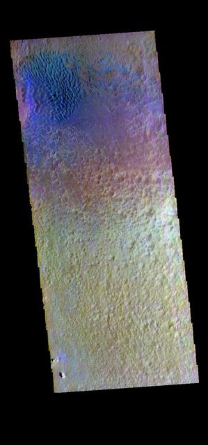
This false color image shows sand dunes on the floor of Hale Crater. This 150 km x 125 km (93 miles x 77 miles) crater is located north of Argyre Planitia. Dark blue in this false color combination usually indicates basaltic sand. The THEMIS VIS camera contains 5 filters. The data from different filters can be combined in multiple ways to create a false color image. These false color images may reveal subtle variations of the surface not easily identified in a single band image. Orbit Number: 66554 Latitude: -35.7883 Longitude: 323.039 Instrument: VIS Captured: 2016-12-14 22:52 https://photojournal.jpl.nasa.gov/catalog/PIA23629
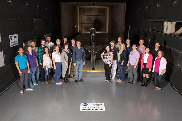
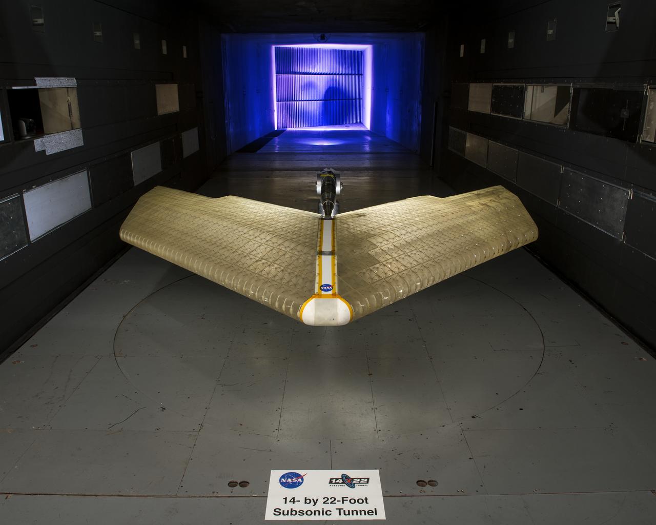
Mission Adaptive Digital Composite Aerostructure Technologies (MADCAT) model in the 14x22 test section, building 1212C For more information go to NASA.gov article. April 3, 2019 "What is MADCAT?" Flexing Wings for Efficient Flight
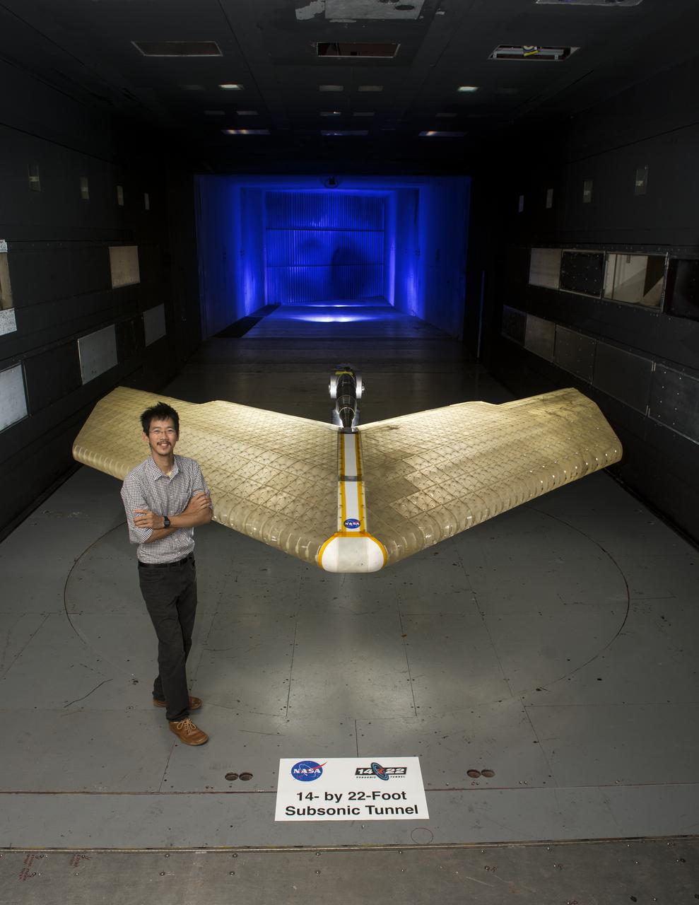
Mission Adaptive Digital Composite Aerostructure Technologies (MADCAT) model in the 14x22 test section, building 1212C, Kenny Cheung from Ames Research Center in photograph. For more information go to NASA.gov article. April 3, 2019 "What is MADCAT?" Flexing Wings for Efficient Flight

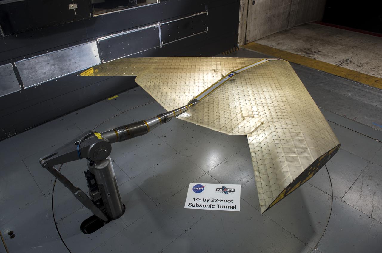
Mission Adaptive Digital Composite Aerostructure Technologies (MADCAT) model in the 14x22 test section. Interior of Structure. For more information go to NASA.gov article. April 3, 2019 "What is MADCAT?" Flexing Wings for Efficient Flight

Mission Adaptive Digital Composite Aerostructure Technologies (MADCAT) model in the 14x22 test section, building 1212C For more information go to NASA.gov article. April 3, 2019 "What is MADCAT?" Flexing Wings for Efficient Flight.
Mission Adaptive Digital Composite Aerostructure Technologies (MADCAT) model in the 14x22 test section, building 1212C. For more information go to NASA.gov article. April 3, 2019 " What is MADCAT? " Flexing Wings for Efficient Flight.

Mission Adaptive Digital Composite Aerostructure Technologies (MADCAT) model in the 14x22 test section. Interior of structure. For more information go to NASA.gov article. April 3, 2019 "What is MADCAT?" Flexing Wings for Efficient Flight
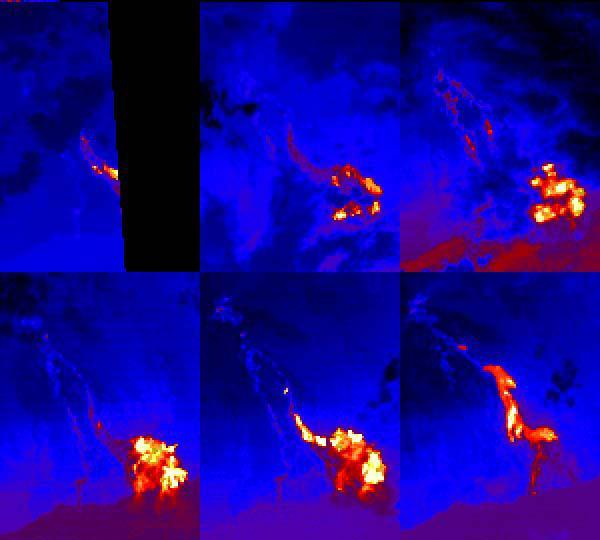
This sequence of ASTER nighttime thermal images shows the Pu'u O'o lava flows entering the sea at Kamokuna on the southeast side of the Island of Hawaii. Each image covers an area of 9 x 12 km. The acquisition dates are April 4 2000, May 13 2000, May 22 2000 (upper row) and June 30 2000, August 1 2000 and January 1 2001 (lower row). Thermal band 14 has been color coded from black (coldest) through blue, red, yellow and white (hottest). The first 5 images show a time sequence of a single eruptive phase; the last image shows flows from a later eruptive phase. The images are located at 19.3 degrees north latitude, 155 degrees west longitude. http://photojournal.jpl.nasa.gov/catalog/PIA11093
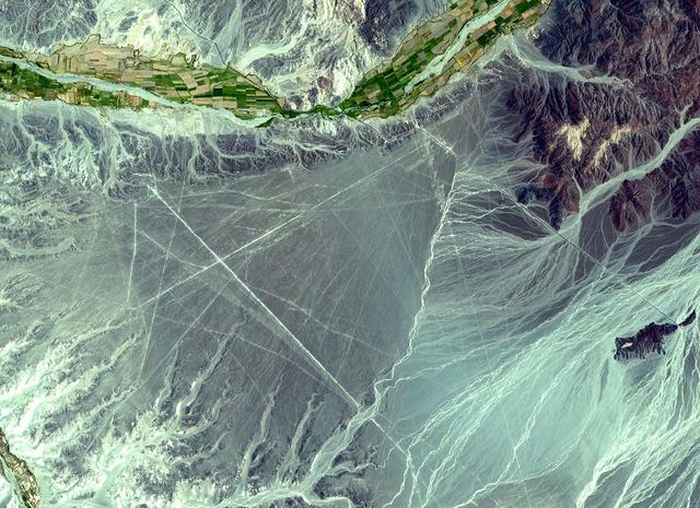
The Nasca Lines are located in the Pampa region of Peru, the desolate plain of the Peruvian coast 400 km south of Lima. The Lines were first spotted when commercial airlines began flying across the Peruvian desert in the 1920's. Passengers reported seeing 'primitive landing strips' on the ground below. The Lines were made by removing the iron-oxide coated pebbles which cover the surface of the desert. When the gravel is removed, they contrast with the light color underneath. In this way the lines were drawn as furrows of a lighter color. On the pampa, south of the Nasca Lines, archaeologists have now uncovered the lost city of the line-builders, Cahuachi. It was built nearly two thousand years ago and was mysteriously abandoned 500 years later. This ASTER sub-image covers an area of 14 x 18 km, was acquired on December 22, 2000, and is located at 14.7 degrees south latitude and 75.1 degrees west longitude. http://photojournal.jpl.nasa.gov/catalog/PIA11097
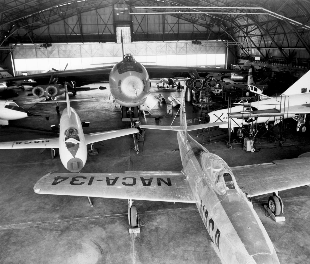
In the center foreground of this 1953 hangar photo is the YF-84A (NACA 134/Air Force 45-59490) used for vortex generator research. It arrived on November 28, 1949, and departed on April 21, 1954. Beside it is the third D-558-1 aircraft (NACA 142/Navy 37972). This aircraft was used for a total of 78 transonic research flights from April 1949 to June 1954. It replaced the second D-558-1, lost in the crash which killed Howard Lilly. Just visible on the left edge is the nose of the first D-558-2 (NACA 143/Navy 37973). Douglas turned the aircraft over to NACA on August 31, 1951, after the contractor had completed its initial test flights. NACA only made a single flight with the aircraft, on September 17, 1956, before the program was cancelled. In the center of the photo is the B-47A (NACA 150/Air Force 49-1900). The B-47 jet bomber, with its thin, swept-back wings, and six podded engines, represented the state of the art in aircraft design in the early 1950s. The aircraft undertook a number of research activities between May 1953 and its 78th and final research flight on November 22, 1957. The tests showed that the aircraft had a buffeting problem at speeds above Mach 0.8. Among the pilots who flew the B-47 were later X-15 pilots Joe Walker, A. Scott Crossfield, John B. McKay, and Neil A. Armstrong. On the right side of the B-47 is NACA's X-1 (Air Force 46-063). The second XS-1 aircraft built, it was fitted with a thicker wing than that on the first aircraft, which had exceeded Mach 1 on October 14, 1947. Flight research by NACA pilots indicated that this thicker wing produced 30 percent more drag at transonic speeds compared to the thinner wing on the first X-1. After a final flight on October 23, 1951, the aircraft was grounded due to the possibility of fatigue failure of the nitrogen spheres used to pressurize the fuel tanks. At the time of this photo, in 1953, the aircraft was in storage. In 1955, the aircraft was extensively modified, becoming the X-1E. In front o
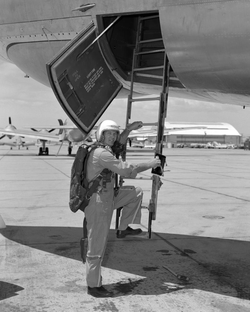
From December 10, 1966, until his retirement on February 27, 1976, Stanley P. Butchart served as Chief (later, Director) of Flight Operations at NASA's Flight Research Center (renamed on March 26, 1976, the Hugh L. Dryden Flight Research Center). Initially, his responsibilities in this position included the Research Pilots Branch, a Maintenance and Manufacturing Branch, and an Operations Engineering Branch, the last of which not only included propulsion and electrical/electronic sections but project engineers for the X-15 and lifting bodies. During his tenure, however, the responsibilities of his directorate came to include not only Flight Test Engineering Support but Flight Systems and Loads laboratories. Before becoming Chief of Flight Operations, Butchart had served since June of 1966 as head of the Research Pilots Branch (Chief Pilot) and then as acting chief of Flight Operations. He had joined the Center (then known as the National Advisory Committee for Aeronautics' High-Speed Flight Research Station) as a research pilot on May 10, 1951. During his career as a research pilot, he flew a great variety of research and air-launch aircraft including the D-558-I, D-558-II, B-29 (plus its Navy version, the P2B), X-4, X-5, KC-135, CV-880, CV-990, B-47, B-52, B-747, F-100A, F-101, F-102, F-104, PA-30 Twin Comanche, JetStar, F-111, R4D, B-720, and B-47. Although previously a single-engine pilot, he became the Center's principal multi-engine pilot during a period of air-launches in which the pilot of the air-launch aircraft (B-29 or P2B) basically directed the operations. It was he who called for the chase planes before each drop, directed the positioning of fire rescue vehicles, and released the experimental aircraft after ensuring that all was ready for the drop. As pilot of the B-29 and P2B, Butchart launched the X-1A once, the X-1B 13 times, the X-1E 22 times, and the D-558-II 102 times. In addition, he towed the M2-F1 lightweight lifting body 14 times behind an R4
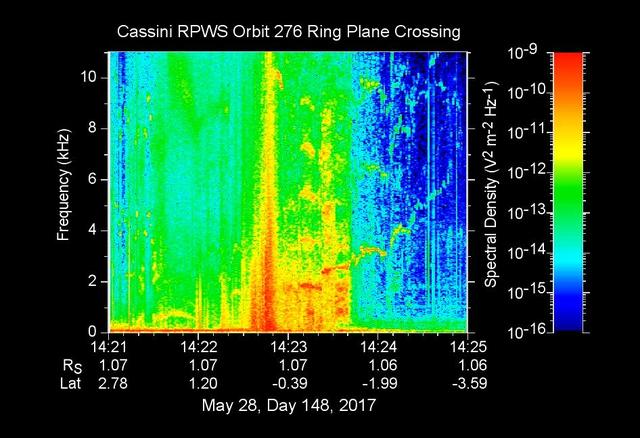
The sounds and colorful spectrogram in this still image and video represent data collected by the Radio and Plasma Wave Science, or RPWS, instrument on NASA's Cassini spacecraft, as it crossed through Saturn's D ring on May 28, 2017. This was the first of four passes through the inner edge of the D ring during the 22 orbits of Cassini's final mission phase, called the Grand Finale. During this ring plane crossing, the spacecraft was oriented so that its large high-gain antenna was used as a shield to protect more sensitive components from possible ring-particle impacts. The three 33-foot-long (10-meter-long) RPWS antennas were exposed to the particle environment during the pass. As tiny, dust-sized particles strike Cassini and the RPWS antennas, the particles are vaporized into tiny clouds of plasma, or electrically excited gas. These tiny explosions make a small electrical signal (a voltage impulse) that RPWS can detect. Researchers on the RPWS team convert the data into visible and audio formats, some like those seen here, for analysis. Ring particle hits sound like pops and cracks in the audio. Particle impacts are seen to increase in frequency in the spectrogram and in the audible pops around the time of ring crossing as indicated by the red/orange spike just before 14:23 on the x-axis. Labels on the x-axis indicate time (top line), distance from the planet's center in Saturn radii, or Rs (middle), and latitude on Saturn beneath the spacecraft (bottom). These data can be compared to those recorded during Cassini's first dive through the gap between Saturn and the D ring, on April 26. While it appeared from those earlier data that there were essentially no particles in the gap, scientists later determined the particles there are merely too small to create a voltage detectable by RPWS, but could be detected using Cassini's dust analyzer instrument. After ring plane crossing (about 14:23 onward) a series of high pitched whistles are heard. The RPWS instrument detects such tones during each of the Grand Finale orbits and the team is working to understand their source. The D ring proved to contain larger ring particles, as expected and recorded here, although the environment was determined to be relatively benign -- with less dust than other faint Saturnian rings Cassini has flown through. https://photojournal.jpl.nasa.gov/catalog/PIA21620
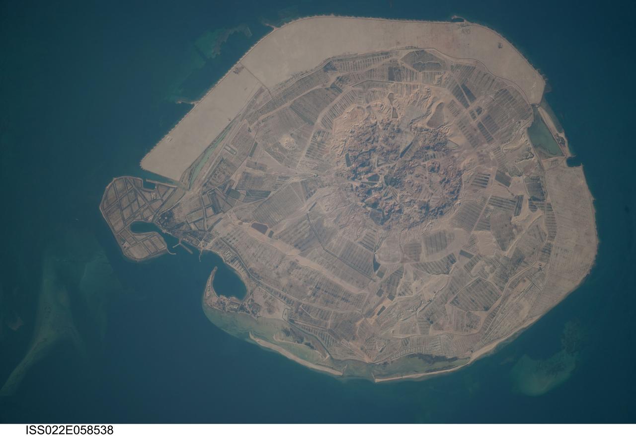
ISS022-E-058538 (31 Jan. 2010) --- Sir Bani Yas Island is featured in this image photographed by an Expedition 22 crew member on the International Space Station. Sir Bani Yas Island is located in the Persian Gulf near the western coastline of the United Arab Emirates (UAE). The approximately 14-kilometers x nine-kilometers island is the surface expression of a salt dome, and is one of several such islands in the Persian Gulf. During past periods of alternating wet and dry climate, sometimes involving areas with high rates of evaporation in enclosed basins, thick layers of salt minerals (such as halite ? common table salt, or gypsum ? a major component of wallboard) were deposited. These layers were subsequently buried by sediments; with enough overlaying material and depth of burial, the salt layers can begin to flow. Salt has lower density than the surrounding rock and it tends to flow upwards, pushing up the overlaying layers of rock to form a salt dome. While many salt domes retain a cap of the youngest rock layers at the surface, in some cases the underlaying salt extrudes onto the surface. This photograph illustrates the varying character of surfaces on the island. The central mountains of Jebel Wahid (center) mark the location of the Sir Bani Yas salt dome. The dome has breached the surface but exposed salt - primarily gypsum - is removed by erosion, leaving a rugged, insoluble cap formed from fragments of the overlaying sedimentary and volcanic rocks. Sand and silt derived from the Jebel Wahid area and surrounding gravel cover forms beaches along the outer edge of the island.

International Microgravity Laboratory-1 (IML-1) was the first in a series of Shuttle flights dedicated to fundamental materials and life sciences research with the international partners. The participating space agencies included: NASA, the 14-nation European Space Agency (ESA), the Canadian Space Agency (CSA), the French National Center of Space Studies (CNES), the German Space Agency and the German Aerospace Research Establishment (DAR/DLR), and the National Space Development Agency of Japan (NASDA). Dedicated to the study of life and materials sciences in microgravity, the IML missions explored how life forms adapt to weightlessness and investigated how materials behave when processed in space. Both life and materials sciences benefited from the extended periods of microgravity available inside the Spacelab science module in the cargo bay of the Space Shuttle Orbiter. In this photograph, Astronauts Stephen S. Oswald and Norman E. Thagard handle ampoules used in the Mercuric Iodide Crystal Growth (MICG) experiment. Mercury Iodide crystals have practical uses as sensitive x-ray and gamma-ray detectors. In addition to their exceptional electronic properties, these crystals can operate at room temperature rather than at the extremely low temperatures usually required by other materials. Because a bulky cooling system is urnecessary, these crystals could be useful in portable detector devices for nuclear power plant monitoring, natural resource prospecting, biomedical applications in diagnosis and therapy, and astronomical observation. Managed by the Marshall Space Flight Center, IML-1 was launched on January 22, 1992 aboard the Space Shuttle Orbiter Discovery (STS-42 mission).