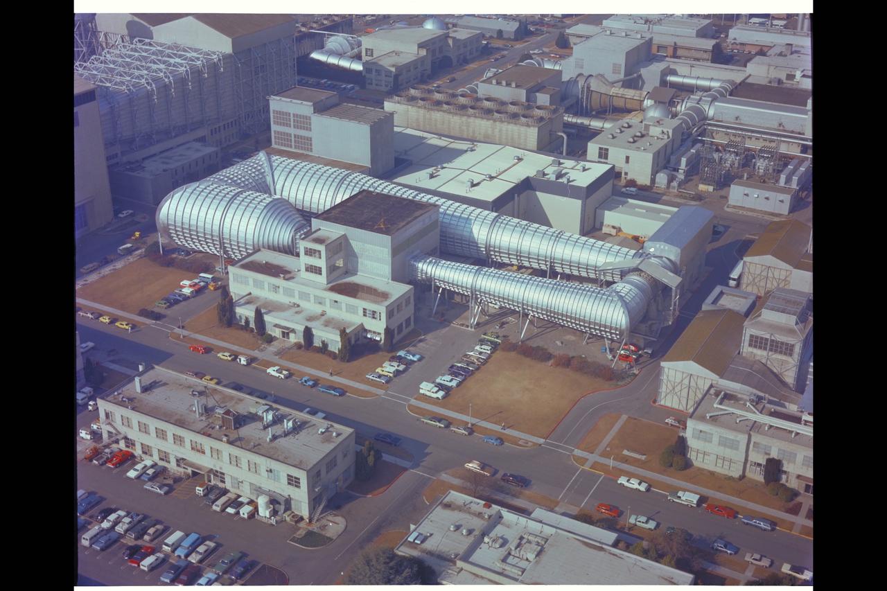
NASA Ames Research Center 14-foot Transonic Wind Tunnel
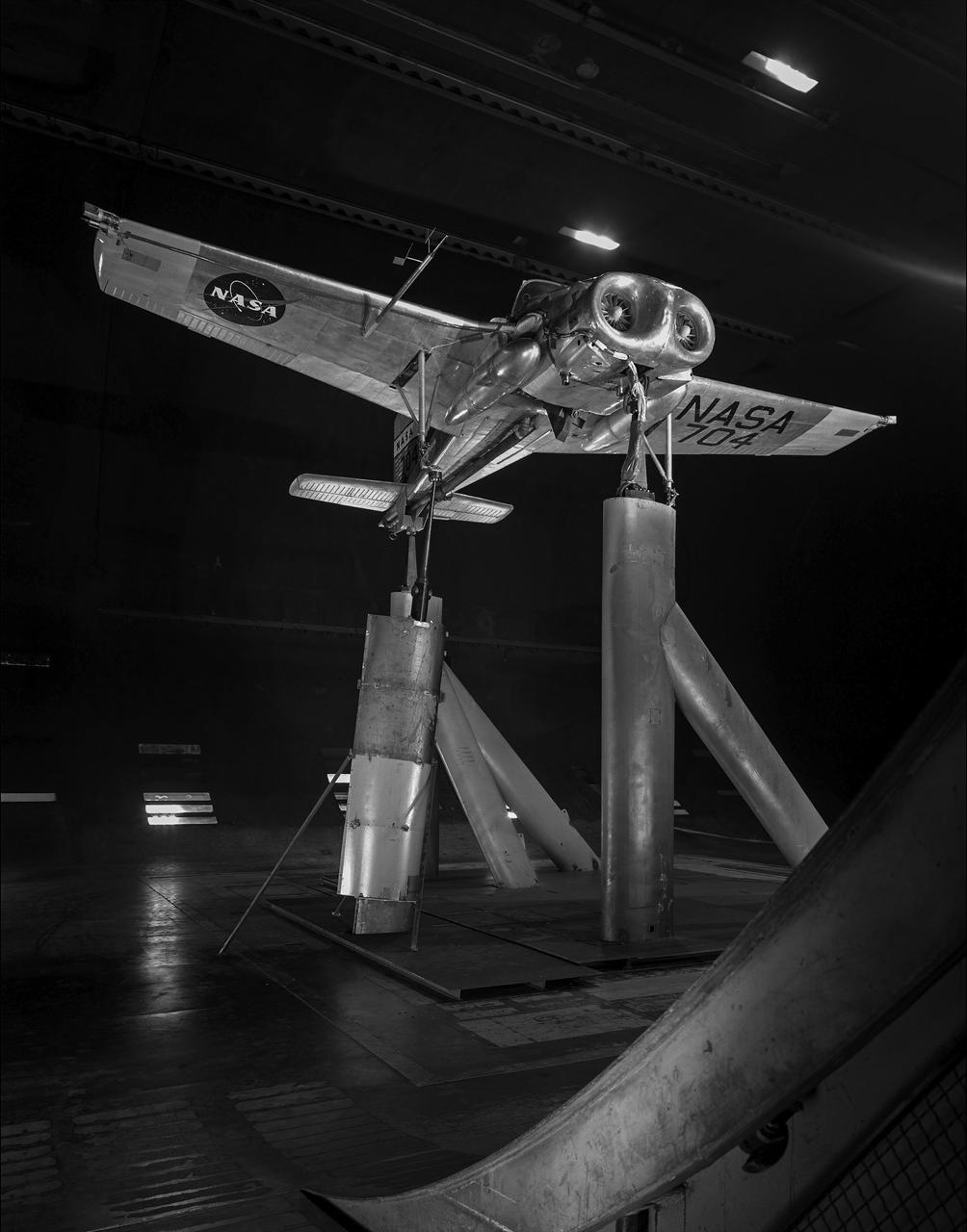
Bell V/STOL X-14 airplane mounted at 90 degrees yaw in 40x80 foot wind tunnel.
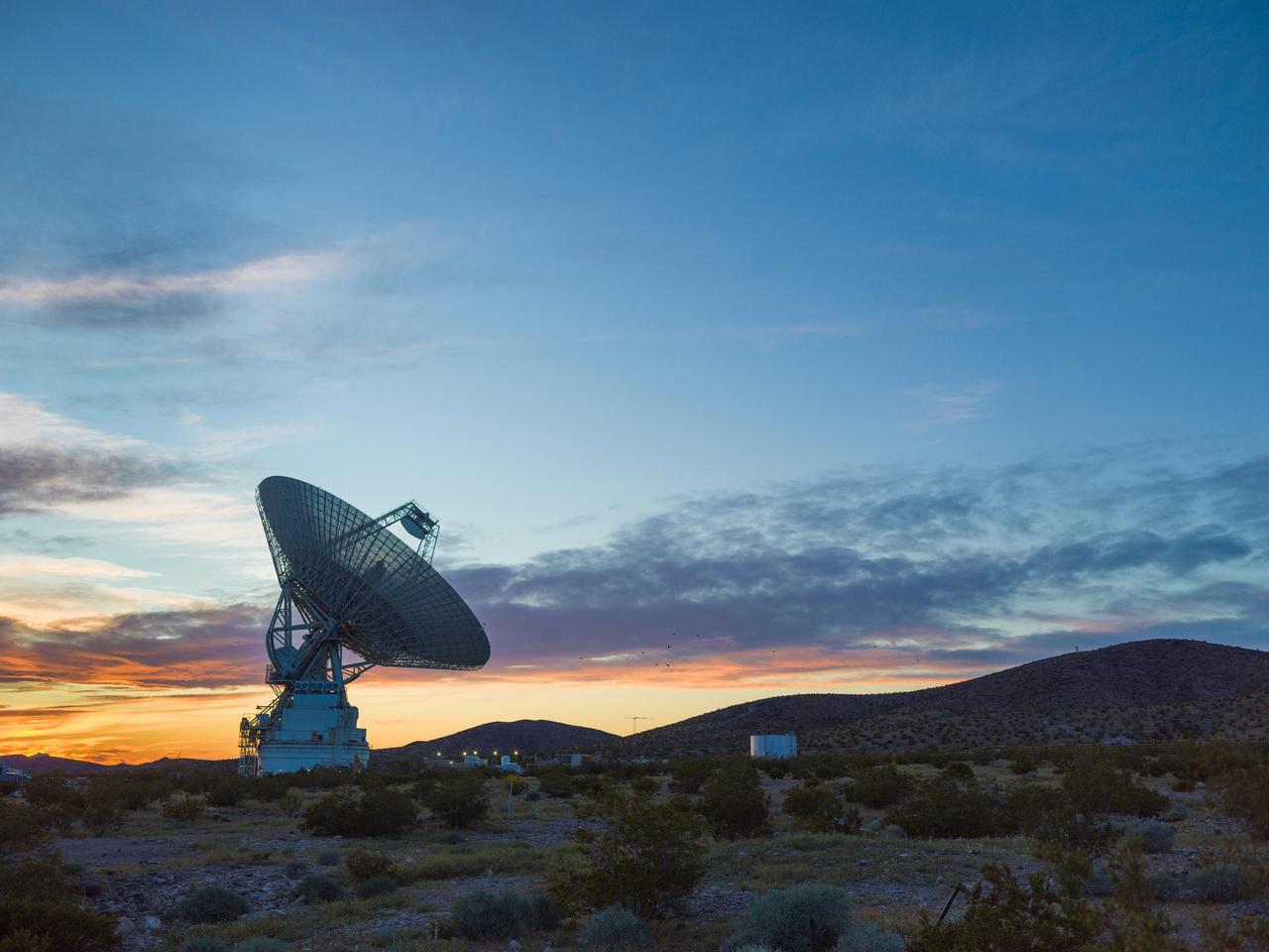
This sunset photo shows Deep Space Station 14 (DSS-14), the 230-foot-wide (70-meter) antenna at the Goldstone Deep Space Communications Complex near Barstow, California, part of NASA's Deep Space Network. The network's three complexes around the globe support communications with dozens of deep space missions. DSS-14 is also the agency's Goldstone Solar System Radar, which is used to observe asteroids that come close to Earth. https://photojournal.jpl.nasa.gov/catalog/PIA26150
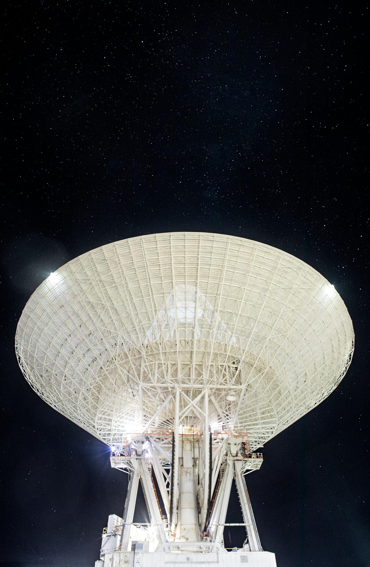
Deep Space Station 14 (DSS-14), the 230-foot-wide (70-meter) antenna at the Goldstone Deep Space Communications Complex near Barstow, California, points up toward a starry sky in September 2025. Goldstone is part of NASA’s Deep Space Network (DSN), which operates three complexes around the globe to support communications with dozens of deep space missions. DSS-14 is also the agency’s Goldstone Solar System Radar, which is used to observe asteroids that come close to Earth. For more information about the DSN, visit: https://www.nasa.gov/communicating-with-missions/dsn/

Asteroid 1998 WT24 left in December 2001, right on December 11, 2015 taken by NASA the 230-foot 70-meter DSS-14 antenna at Goldstone, California.
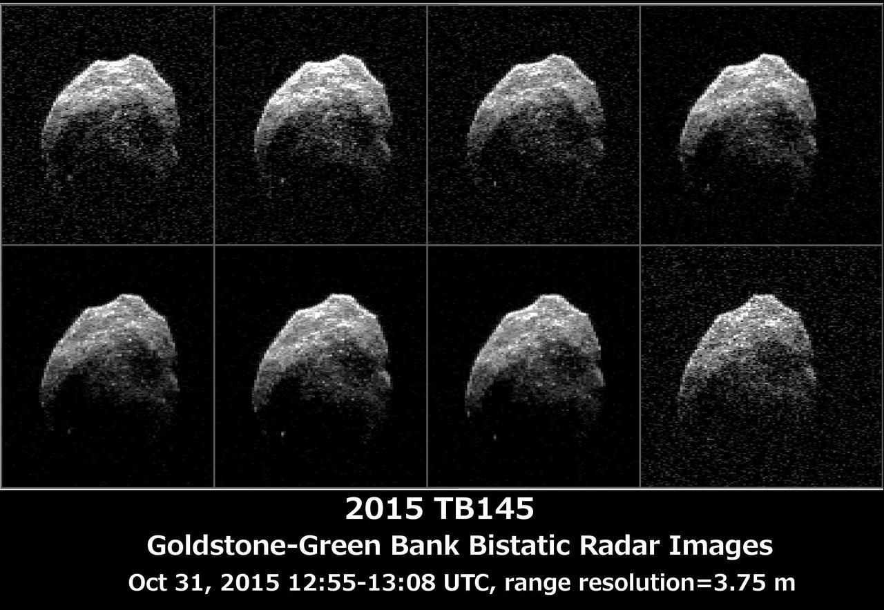
The 230-foot 70-meter DSS-14 antenna at Goldstone, Ca. obtained these radar images of asteroid 2015 TB145 on Oct. 31, 2015. Asteroid 2015 TB145 is depicted in eight individual radar images collected on Oct. 31, 2015 between 5:55 a.m. PDT (8:55 a.m. EDT) and 6:08 a.m. PDT (9:08 a.m. EDT). At the time the radar images were taken, the asteroid was between 440,000 miles (710,000 kilometers) and about 430,000 miles (690,000 kilometers) distant. Asteroid 2015 TB145 safely flew past Earth on Oct. 31, at 10:00 a.m. PDT (1 p.m. EDT) at about 1.3 lunar distances (300,000 miles, 480,000 kilometers). To obtain the radar images, the scientists used the 230-foot (70-meter) DSS-14 antenna at Goldstone, California, to transmit high power microwaves toward the asteroid. The signal bounced of the asteroid, and their radar echoes were received by the National Radio Astronomy Observatory's 100-meter (330-foot) Green Bank Telescope in West Virginia. The images achieve a spatial resolution of about 13 feet (4 meters) per pixel. http://photojournal.jpl.nasa.gov/catalog/PIA20043
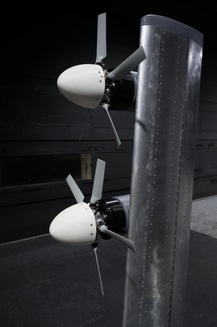
In May and June, NASA researchers tested a 7-foot wing model in the 14-by-22-Foot Subsonic Wind Tunnel at NASA’s Langley Research Center in Hampton, Virginia. The team collected data on critical propeller-wing interactions over the course of several weeks
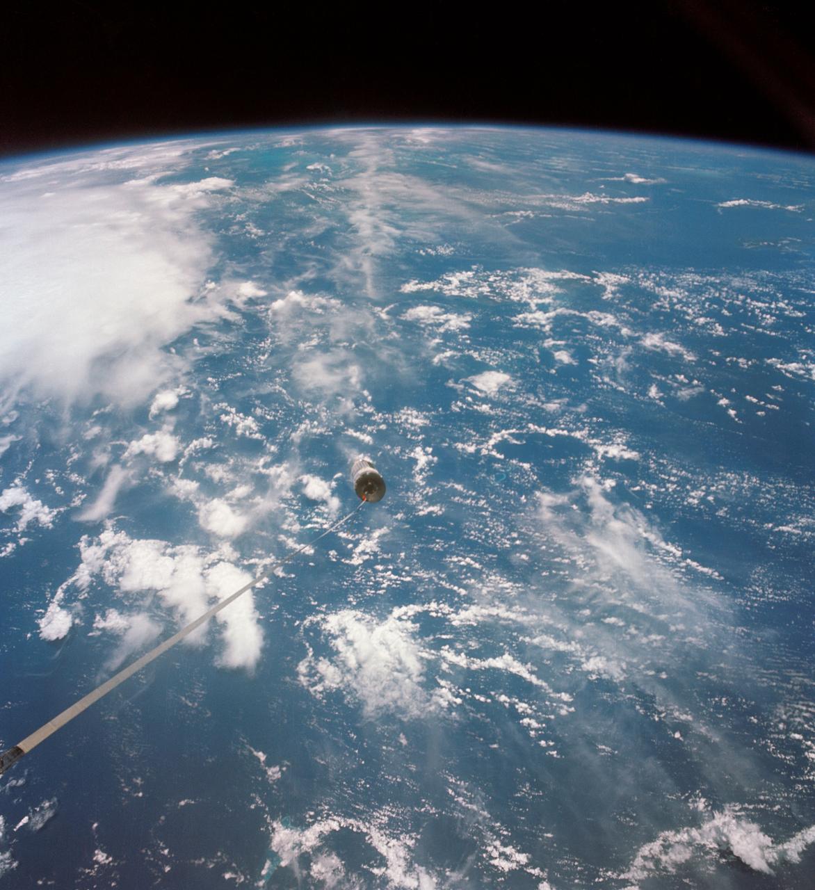
S66-54571 (14 Sept. 1966) --- A 100-foot tether line connects the Agena Target Docking Vehicle with the Gemini-11 spacecraft during its 32nd revolution of Earth. Photo credit: NASA

NASA employees Broderic J. Gonzalez, left, and David W. Shank, right, install pieces of a 7-foot wing model in preparation for testing in the 14-by-22-Foot Subsonic Wind Tunnel at NASA's Langley Research Center in Hampton, Virginia, in May 2025. The lessons learned from this testing will be shared with the public to support advanced air mobility aircraft development.
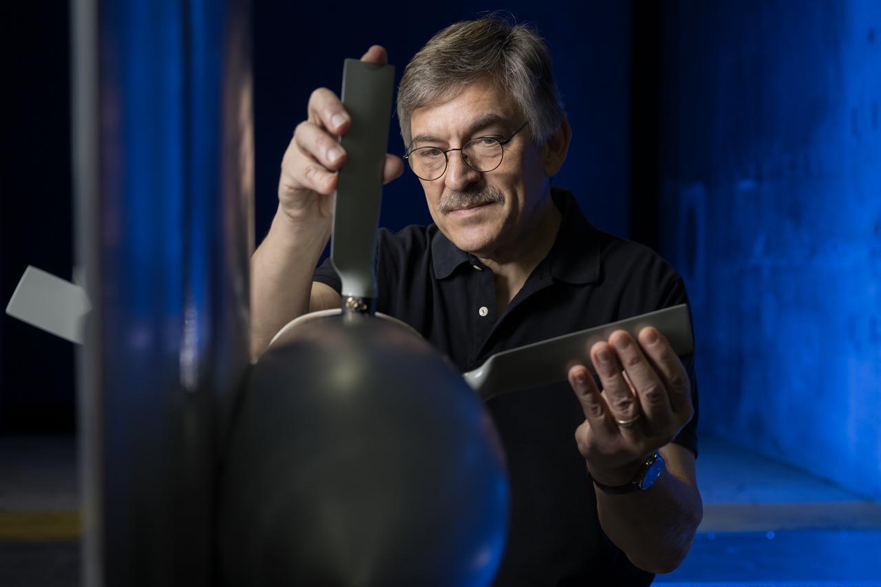
NASA researcher Norman W. Schaeffler adjusts a propellor, which is part of a 7-foot wing model that was recently tested at NASA’s Langley Research Center in Hampton, Virginia. In May and June, NASA researchers tested the wing in the 14-by-22-Foot Subsonic Wind Tunnel to collect data on critical propeller-wing interactions. The lessons learned from this testing will be shared with the public to support advanced air mobility aircraft development.
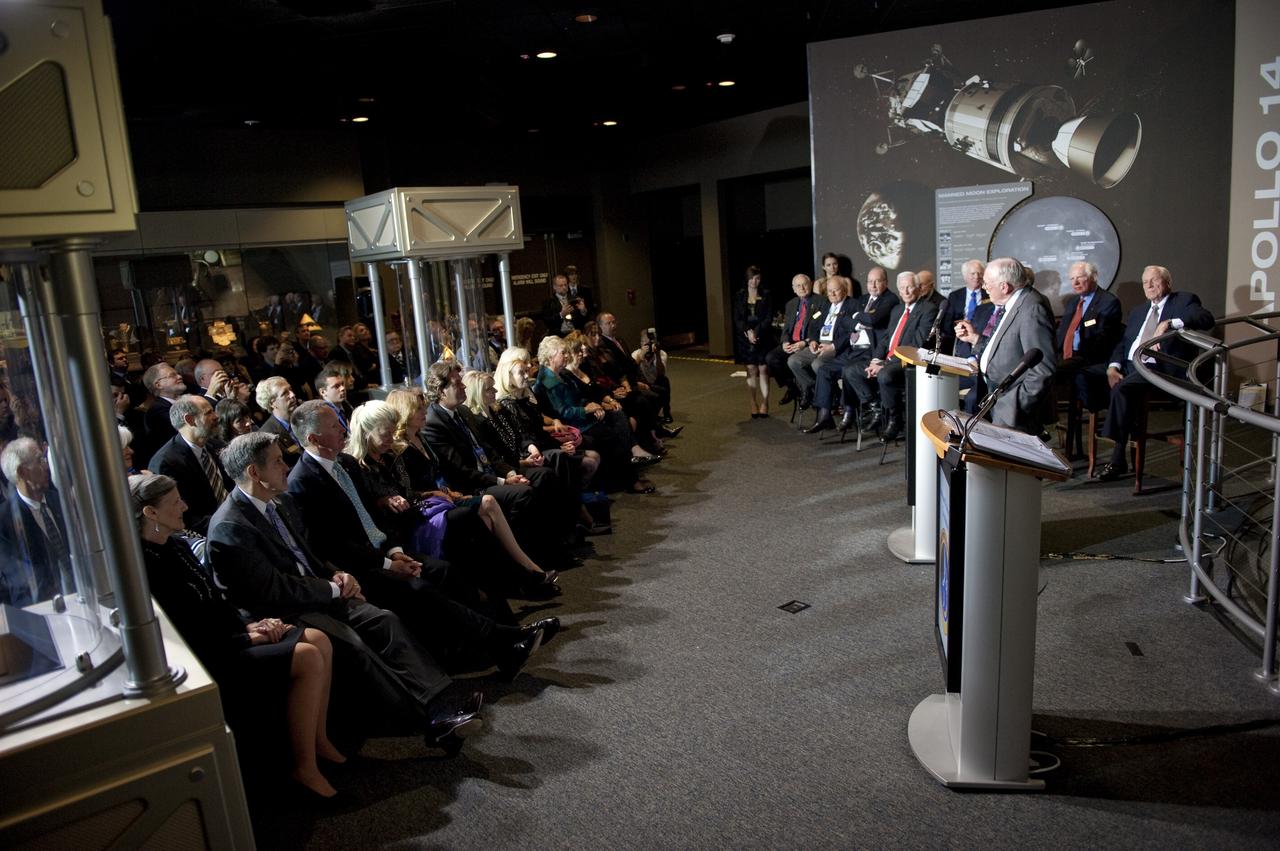
CAPE CANAVERAL, Fla. -- Apollo 11 Commander Neil Armstrong talks to attendees of the Apollo 14 Anniversary Soirée at the Kennedy Space Center Visitor Complex's Saturn V Center. The celebration was hosted by the Astronaut Scholarship Foundation. Apollo 14 landed on the lunar surface 40 years ago on Feb. 5, 1971. In 1969, Armstrong gained the distinction of being the first human to step foot on the surface of the moon. Photo credit: NASA/Kim Shiflett
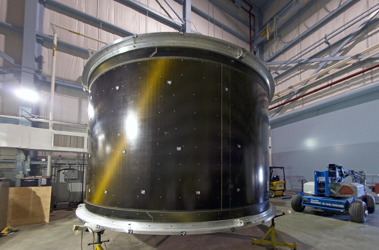
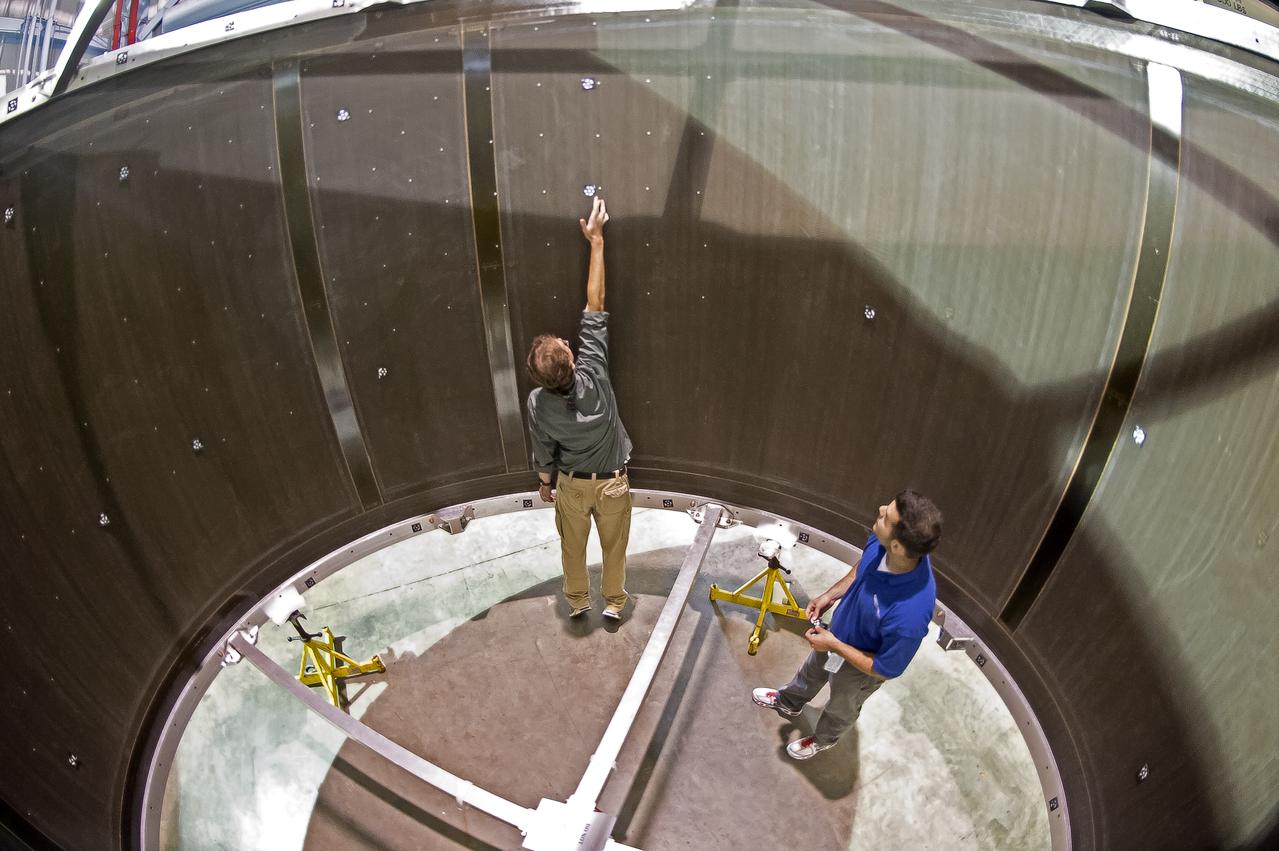
White light shape and measurement of a 13.1 Foot diameter fluted-core sandwich composite test article designed by LaRC and fabricated by Boeing Under Space Act Agreement SAA1-737, Annex 14. to be tested in LaRC's combined Loads Testing System (COLTS).
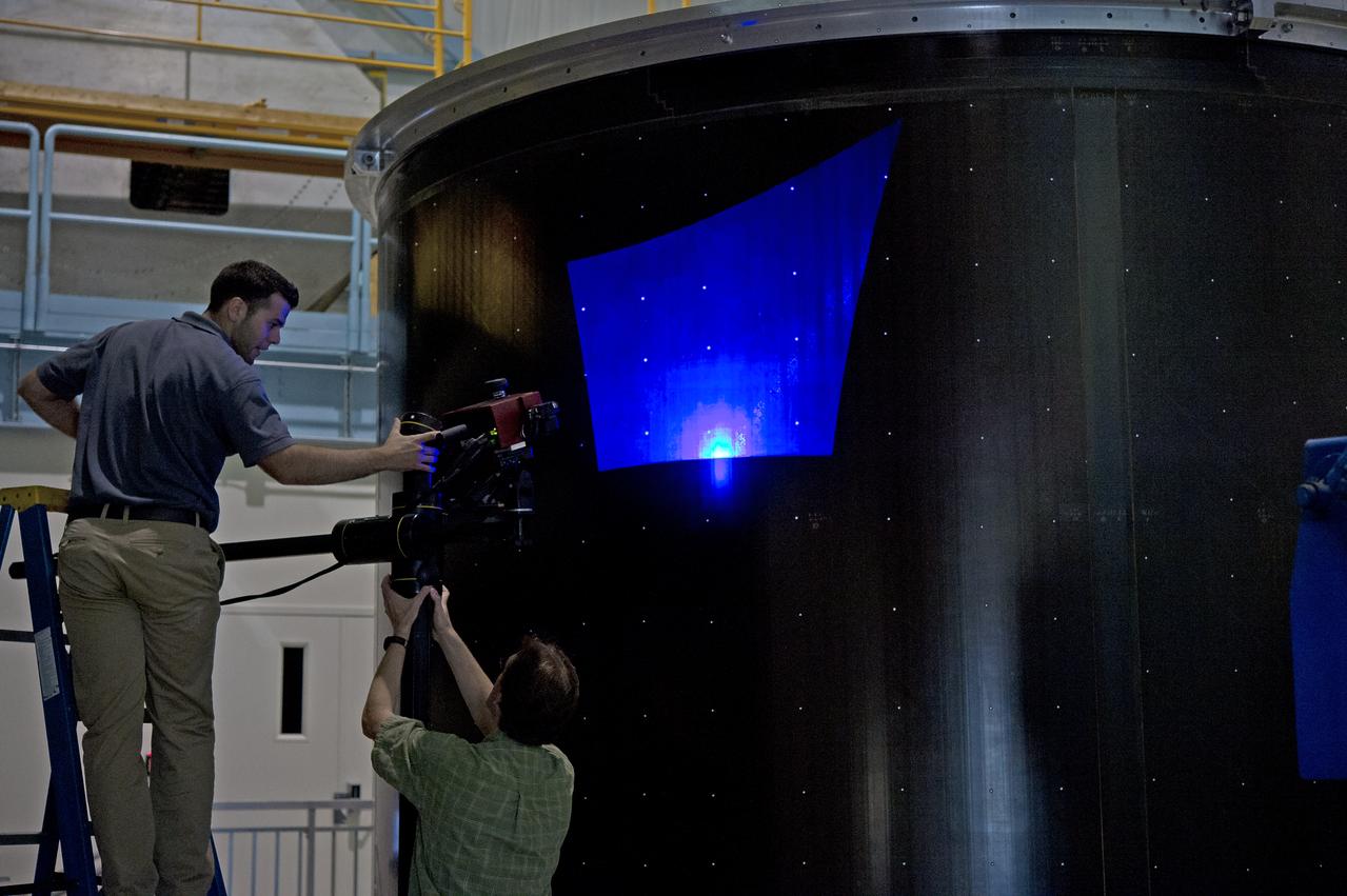
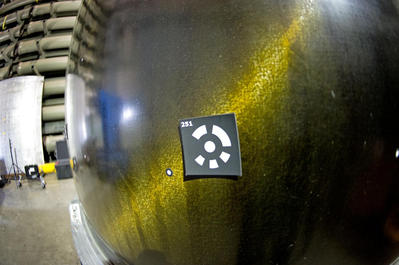
White light shape and measurement of a 13.1 Foot diameter fluted-core sandwich composite test article designed by LaRC and fabricated by Boeing Under Space Act Agreement SAA1-737, Annex 14. to be tested in LaRC's combined Loads Testing System (COLTS).
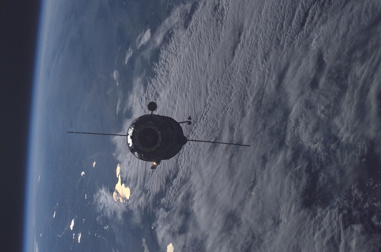
Enroute for docking, the 16-foot-long Russian docking compartment Pirs (the Russian word for pier) approaches the International Space Station (ISS). Pirs will provide a docking port for future Russian Soyuz or Progress craft, as well as an airlock for extravehicular activities. Pirs was launched September 14, 2001 from Baikonur in Russia.
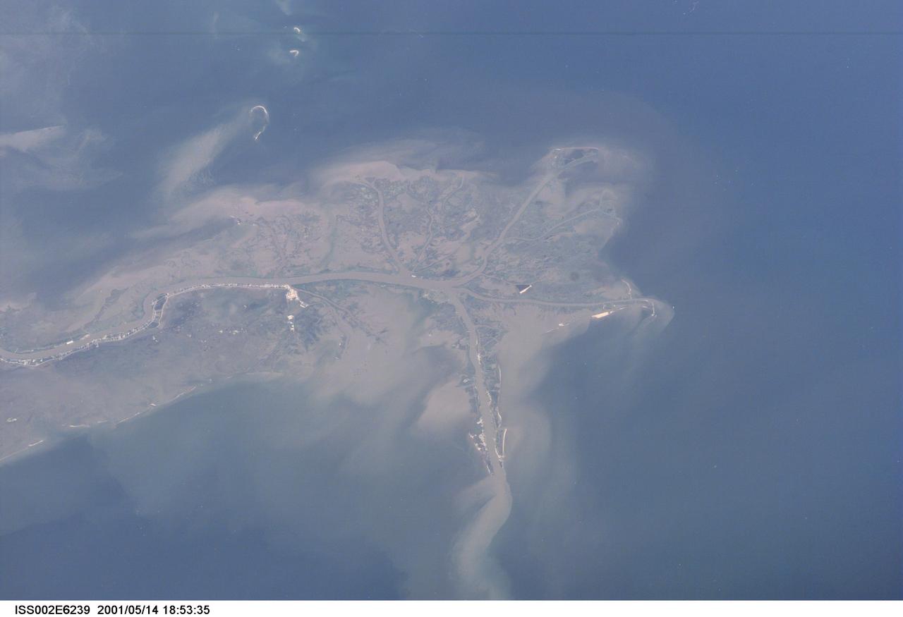
ISS002-E-6239 (14 May 2001) --- This digital still camera's image, recorded by one of the Expedition Two crew members aboard the International Space Station, features the mouth of the Mississippi River. The distribution of riverborne sediments is clearly evident in the Gulf of Mexico. This delta area is often referred to as the "crow's foot."
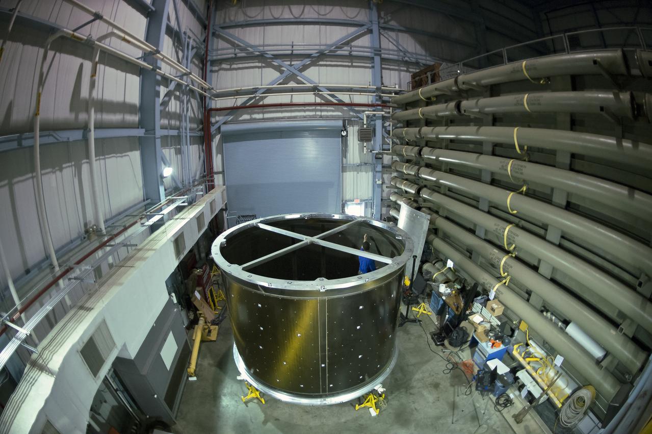
White light shape and measurement of a 13.1 Foot diameter fluted-core sandwich composite test article designed by LaRC and fabricated by Boeing Under Space Act Agreement SAA1-737, Annex 14. to be tested in LaRC's combined Loads Testing System (COLTS).
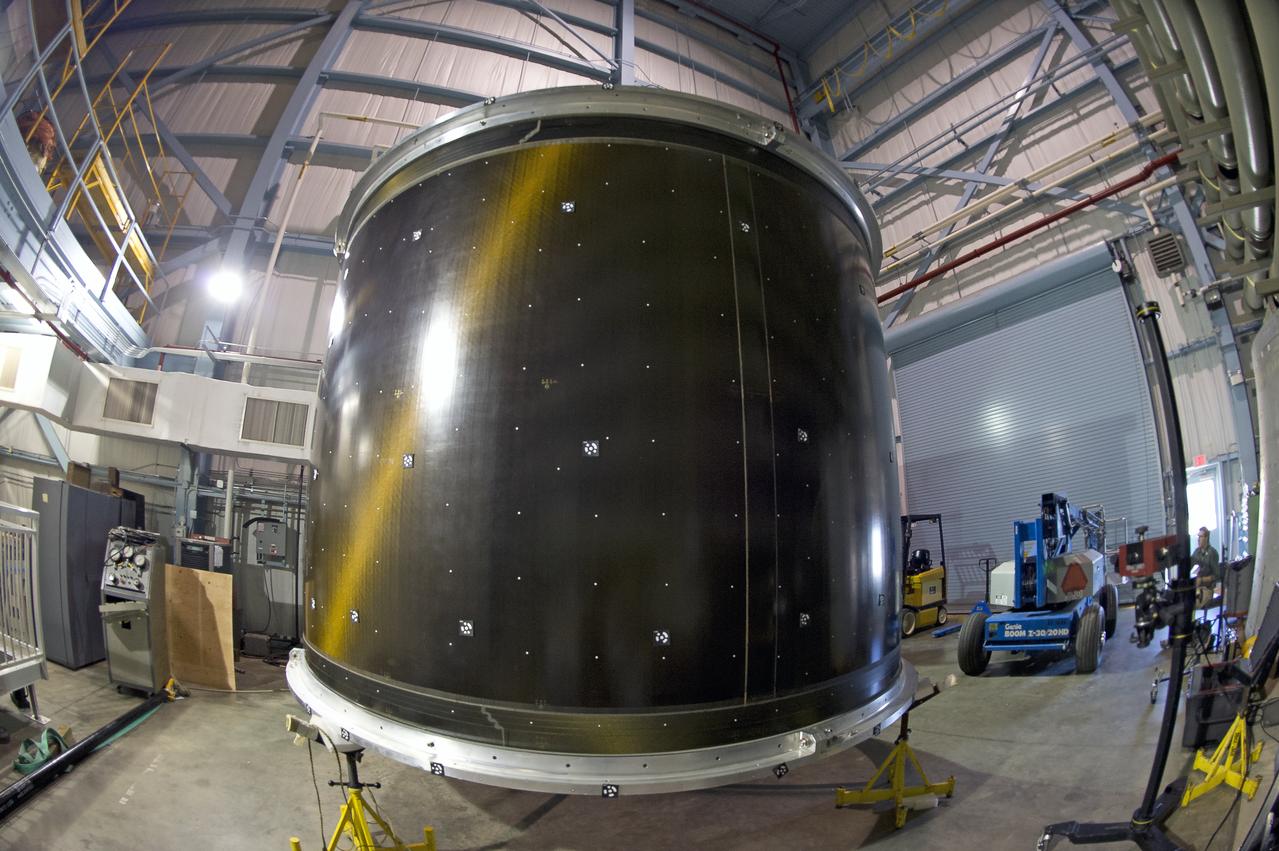
White light shape and measurement of a 13.1 Foot diameter fluted-core sandwich composite test article designed by LaRC and fabricated by Boeing Under Space Act Agreement SAA1-737, Annex 14. to be tested in LaRC's combined Loads Testing System (COLTS).
White light shape and measurement of a 13.1 Foot diameter fluted-core sandwich composite test article designed by LaRC and fabricated by Boeing Under Space Act Agreement SAA1-737, Annex 14. to be tested in LaRC's combined Loads Testing System (COLTS).
White light shape and measurement of a 13.1 Foot diameter fluted-core sandwich composite test article designed by LaRC and fabricated by Boeing Under Space Act Agreement SAA1-737, Annex 14. to be tested in LaRC's combined Loads Testing System (COLTS).
White light shape and measurement of a 13.1 Foot diameter fluted-core sandwich composite test article designed by LaRC and fabricated by Boeing Under Space Act Agreement SAA1-737, Annex 14. to be tested in LaRC's combined Loads Testing System (COLTS).
White light shape and measurement of a 13.1 Foot diameter fluted-core sandwich composite test article designed by LaRC and fabricated by Boeing Under Space Act Agreement SAA1-737, Annex 14. to be tested in LaRC's combined Loads Testing System (COLTS).

White light shape and measurement of a 13.1 Foot diameter fluted-core sandwich composite test article designed by LaRC and fabricated by Boeing Under Space Act Agreement SAA1-737, Annex 14. to be tested in LaRC's combined Loads Testing System (COLTS).
White light shape and measurement of a 13.1 Foot diameter fluted-core sandwich composite test article designed by LaRC and fabricated by Boeing Under Space Act Agreement SAA1-737, Annex 14. to be tested in LaRC's combined Loads Testing System (COLTS).
White light shape and measurement of a 13.1 Foot diameter fluted-core sandwich composite test article designed by LaRC and fabricated by Boeing Under Space Act Agreement SAA1-737, Annex 14. to be tested in LaRC's combined Loads Testing System (COLTS).
White light shape and measurement of a 13.1 Foot diameter fluted-core sandwich composite test article designed by LaRC and fabricated by Boeing Under Space Act Agreement SAA1-737, Annex 14. to be tested in LaRC's combined Loads Testing System (COLTS).

KENNEDY SPACE CENTER, FLA. -- Workers are dwarfed by the fallen 300-foot, five-million-pound Mobile Service Tower (MST) on Launch Complex 41, Cape Canaveral Air Force Station. The MST and a 200-foot-high umbilical tower nearby were demolished to make room for Lockheed Martin's 14-acre Vehicle Integration Facility (VIF), under construction. Only lightning protection towers remain standing at the site. About 200 pounds of linear-shaped charges were used to bring down the towers so that the materials can be recycled. The implosion and removal of the tower debris is expected to be completed in two months. The VIF will be used for Lockheed Martin's Atlas V Launch System.
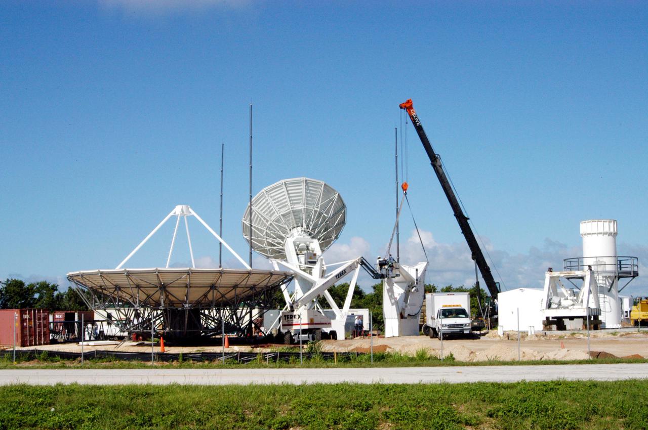
KENNEDY SPACE CENTER, FLA. - On June 14, work is underway on a radar site on North Merritt Island, Fla., constructing a C-band radar antenna (seen at left) and its base. The 50-foot C-band radar will be used for long-term Shuttle missions to track the launches and observe possible debris coming from the Shuttle. In the background (center) is an existing 30-foot C-band Pathfinder radar whose use was demonstrated on the Delta Messenger launch. It will be used on the upcoming two Return to Flight missions. The launch window for the first Return to Flight mission, STS-114, is July 13 to July 31.
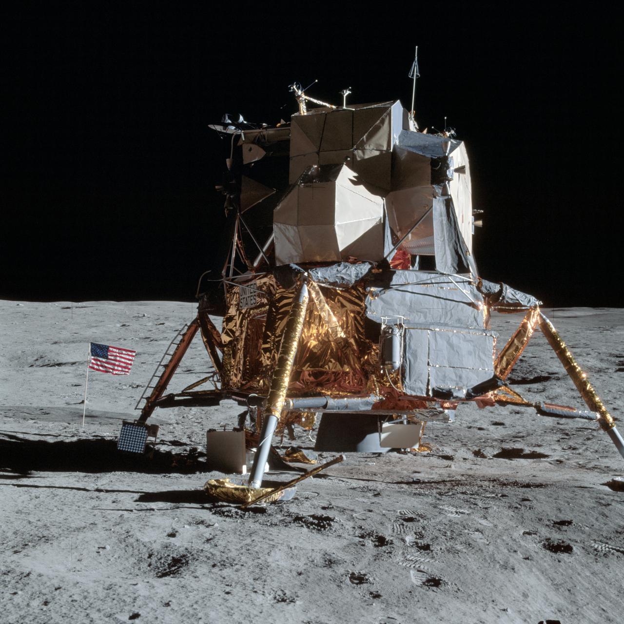
AS14-66-9277 (5 Feb. 1971) --- An excellent view of the Apollo 14 Lunar Module (LM) on the moon, as photographed during the first Apollo 14 extravehicular activity (EVA) on the lunar surface. The astronauts have already deployed the U.S. flag. Note the laser ranging retro reflector (LR-3) at the foot of the LM ladder. The LR-3 was deployed later. While astronauts Alan B. Shepard Jr., commander, and Edgar D. Mitchell, lunar module pilot, descended in the LM to explore the moon, astronaut Stuart A. Roosa, command module pilot, remained with the Command and Service Modules (CSM) in lunar orbit.
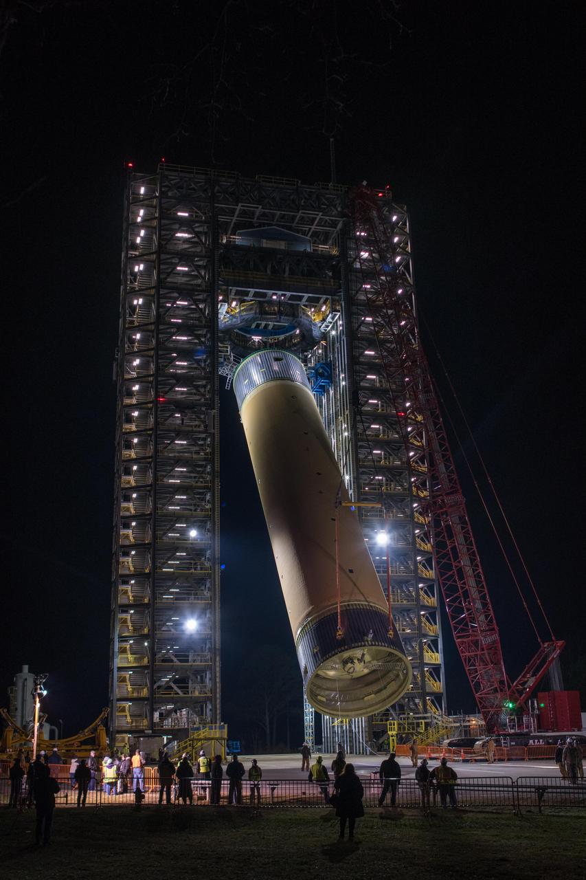
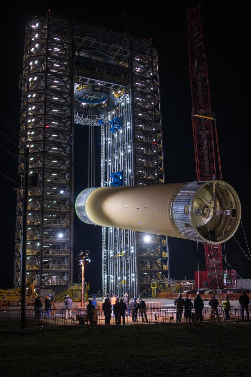
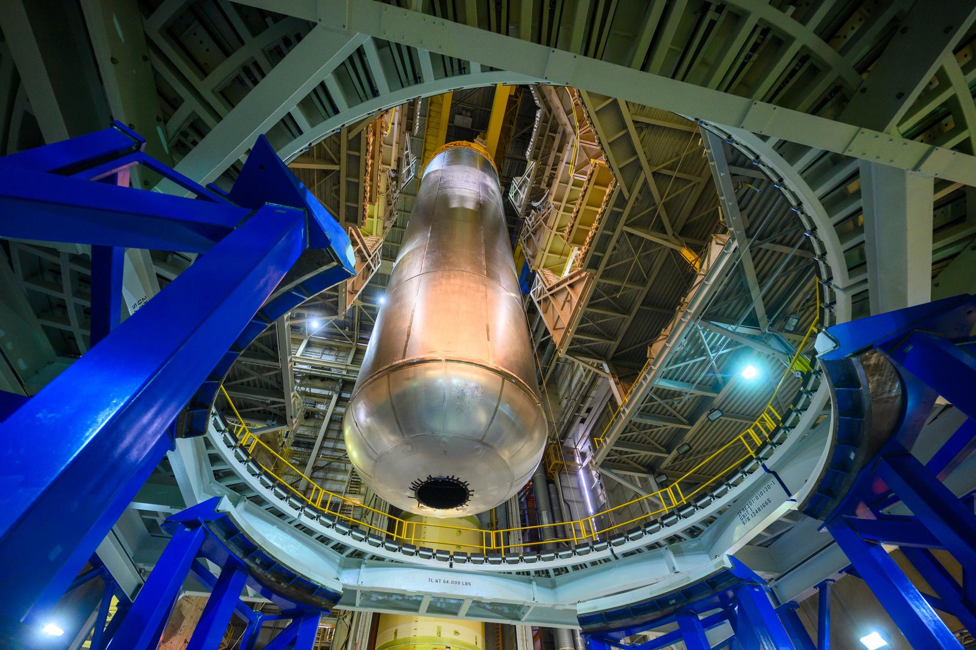
The Space Launch System (SLS) liquid hydrogen tank structural test article is loaded into Test Stand 4693 at NASA’s Marshall Space Flight Center in Huntsville, Alabama, on Jan. 14, 2019. The 149-foot piece of test hardware is the largest piece of structural hardware for the SLS core stage for America’s new deep space rocket Itis structurally identical to the flight version of the tank. It will undergo a series of tests in Test Stand 4693 to simulate the stresses and loads of liftoff and flight. These tests will help ensure designs are adequate for successful SLS missions to the Moon and beyond.
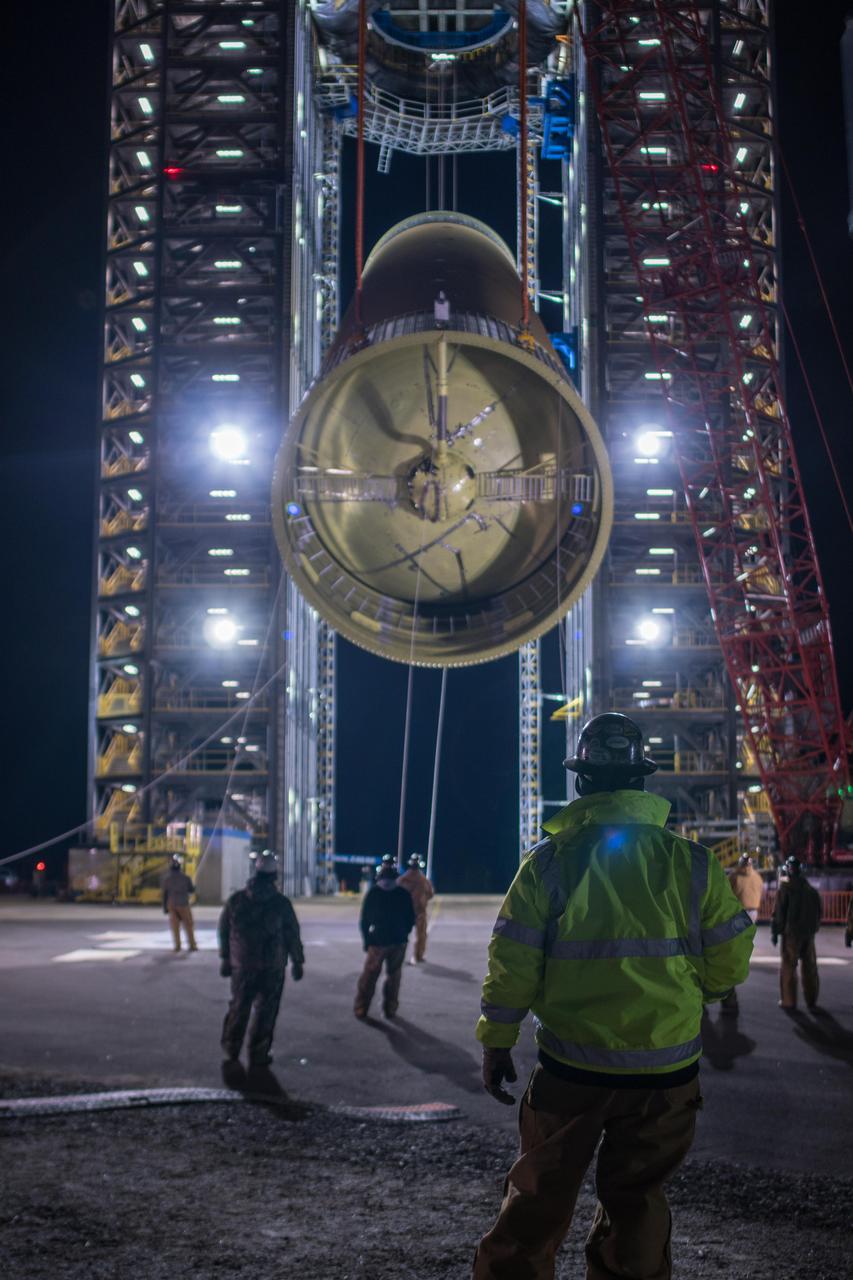
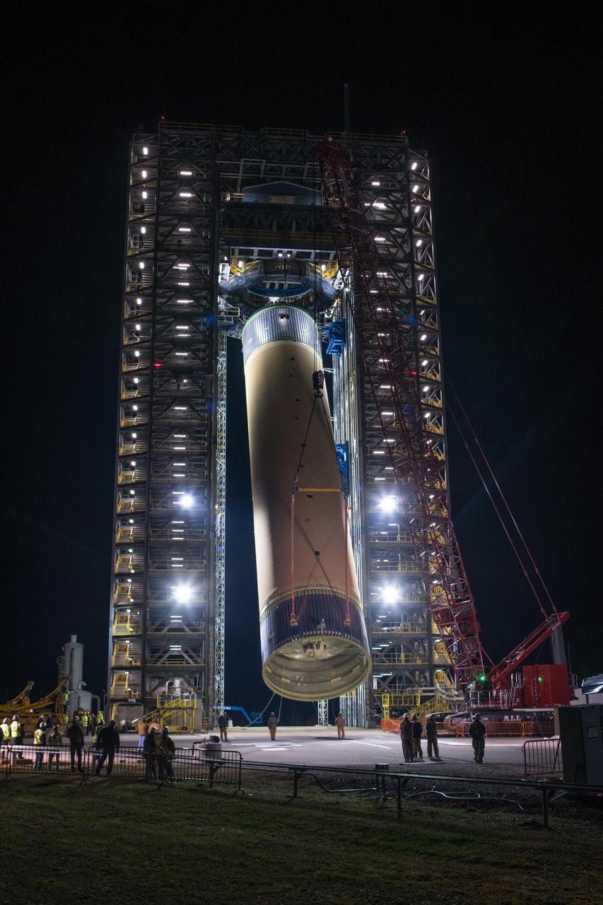
The Space Launch System (SLS) liquid hydrogen tank structural test article is loaded into Test Stand 4693 at NASA’s Marshall Space Flight Center in Huntsville, Alabama, on Jan. 14, 2019. The 149-foot piece of test hardware is the largest piece of structural hardware for the SLS core stage for America’s new deep space rocket Itis structurally identical to the flight version of the tank. It will undergo a series of tests in Test Stand 4693 to simulate the stresses and loads of liftoff and flight. These tests will help ensure designs are adequate for successful SLS missions to the Moon and beyond.
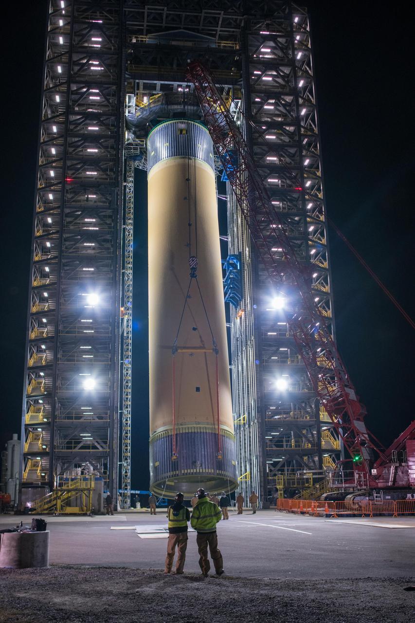
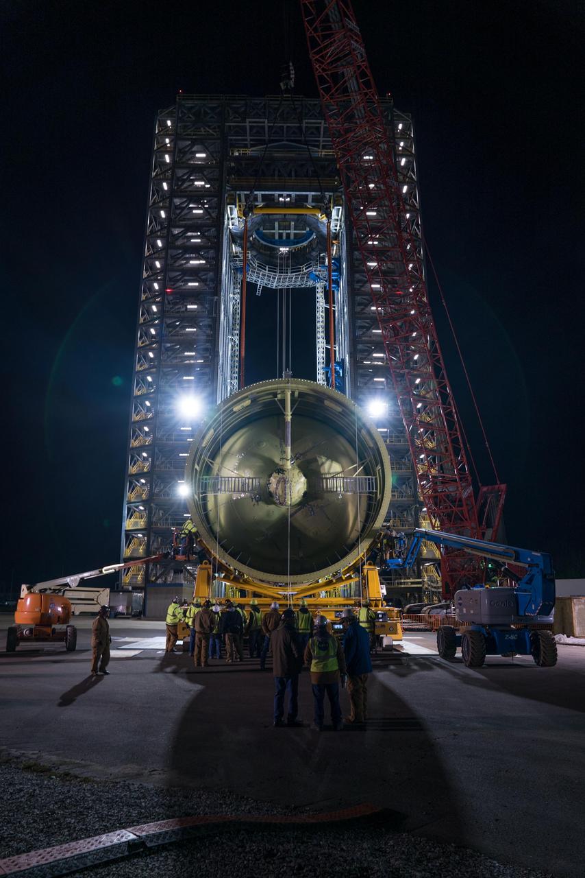
The Space Launch System (SLS) liquid hydrogen tank structural test article is loaded into Test Stand 4693 at NASA’s Marshall Space Flight Center in Huntsville, Alabama, on Jan. 14, 2019. The 149-foot piece of test hardware is the largest piece of structural hardware for the SLS core stage for America’s new deep space rocket Itis structurally identical to the flight version of the tank. It will undergo a series of tests in Test Stand 4693 to simulate the stresses and loads of liftoff and flight. These tests will help ensure designs are adequate for successful SLS missions to the Moon and beyond.
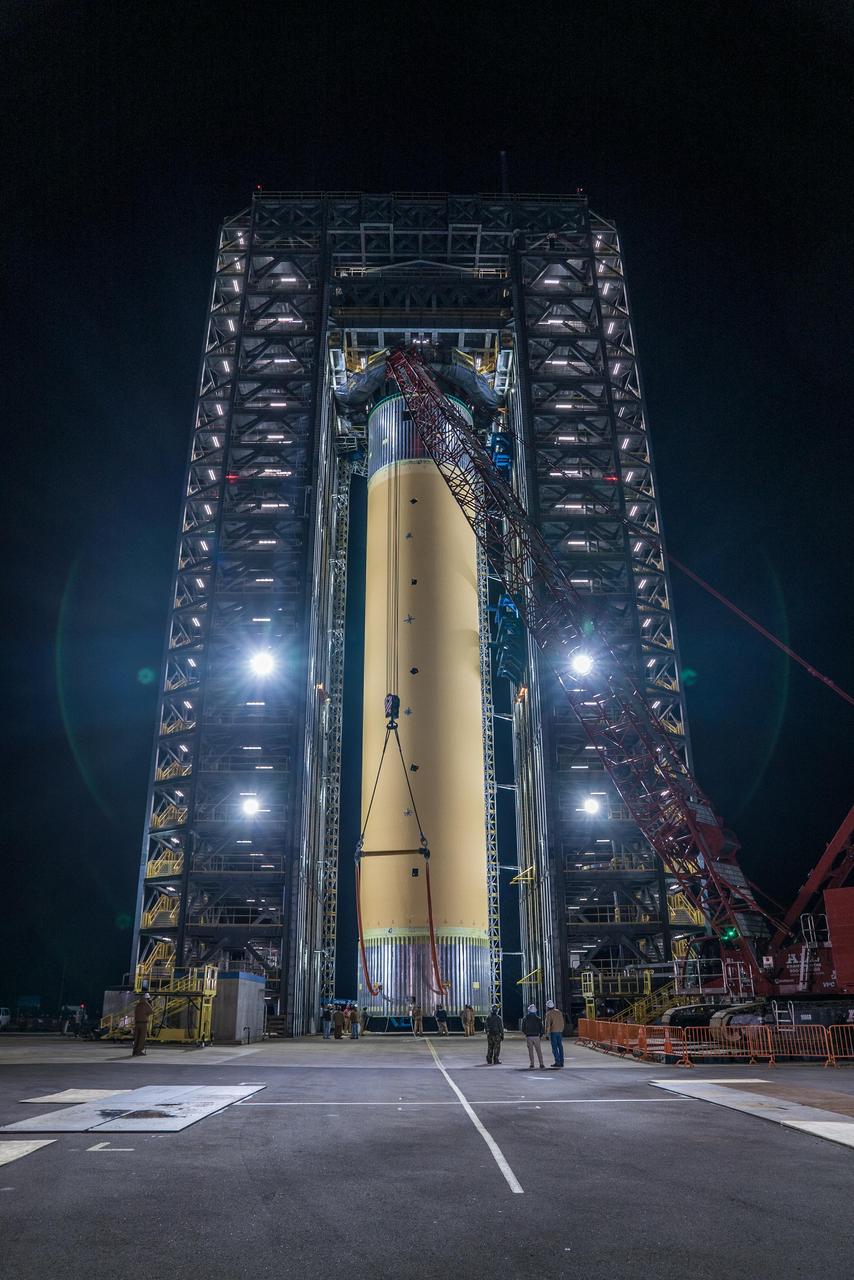
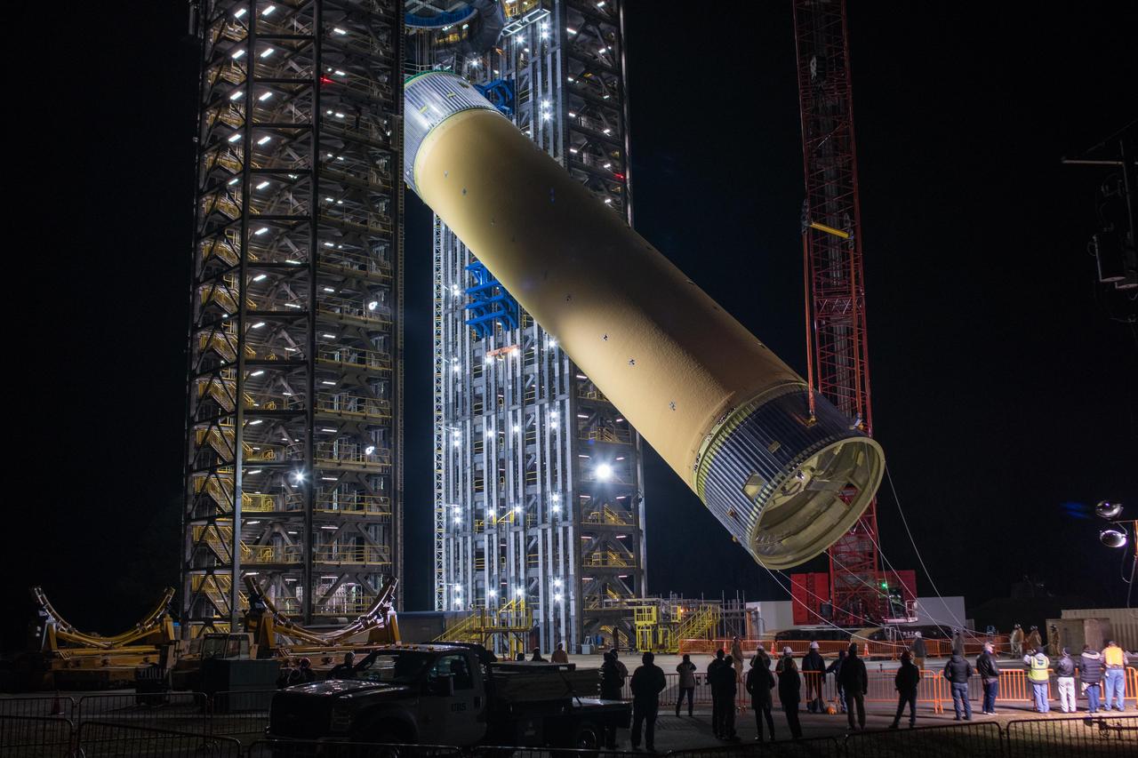
The Space Launch System (SLS) liquid hydrogen tank structural test article is loaded into Test Stand 4693 at NASA’s Marshall Space Flight Center in Huntsville, Alabama, on Jan. 14, 2019. The 149-foot piece of test hardware is the largest piece of structural hardware for the SLS core stage for America’s new deep space rocket Itis structurally identical to the flight version of the tank. It will undergo a series of tests in Test Stand 4693 to simulate the stresses and loads of liftoff and flight. These tests will help ensure designs are adequate for successful SLS missions to the Moon and beyond.
The Space Launch System (SLS) liquid hydrogen tank structural test article is loaded into Test Stand 4693 at NASA’s Marshall Space Flight Center in Huntsville, Alabama, on Jan. 14, 2019. The 149-foot piece of test hardware is the largest piece of structural hardware for the SLS core stage for America’s new deep space rocket Itis structurally identical to the flight version of the tank. It will undergo a series of tests in Test Stand 4693 to simulate the stresses and loads of liftoff and flight. These tests will help ensure designs are adequate for successful SLS missions to the Moon and beyond.
The Space Launch System (SLS) liquid hydrogen tank structural test article is loaded into Test Stand 4693 at NASA’s Marshall Space Flight Center in Huntsville, Alabama, on Jan. 14, 2019. The 149-foot piece of test hardware is the largest piece of structural hardware for the SLS core stage for America’s new deep space rocket Itis structurally identical to the flight version of the tank. It will undergo a series of tests in Test Stand 4693 to simulate the stresses and loads of liftoff and flight. These tests will help ensure designs are adequate for successful SLS missions to the Moon and beyond.
The Space Launch System (SLS) liquid hydrogen tank structural test article is loaded into Test Stand 4693 at NASA’s Marshall Space Flight Center in Huntsville, Alabama, on Jan. 14, 2019. The 149-foot piece of test hardware is the largest piece of structural hardware for the SLS core stage for America’s new deep space rocket Itis structurally identical to the flight version of the tank. It will undergo a series of tests in Test Stand 4693 to simulate the stresses and loads of liftoff and flight. These tests will help ensure designs are adequate for successful SLS missions to the Moon and beyond.
The Space Launch System (SLS) liquid hydrogen tank structural test article is loaded into Test Stand 4693 at NASA’s Marshall Space Flight Center in Huntsville, Alabama, on Jan. 14, 2019. The 149-foot piece of test hardware is the largest piece of structural hardware for the SLS core stage for America’s new deep space rocket Itis structurally identical to the flight version of the tank. It will undergo a series of tests in Test Stand 4693 to simulate the stresses and loads of liftoff and flight. These tests will help ensure designs are adequate for successful SLS missions to the Moon and beyond.
The Space Launch System (SLS) liquid hydrogen tank structural test article is loaded into Test Stand 4693 at NASA’s Marshall Space Flight Center in Huntsville, Alabama, on Jan. 14, 2019. The 149-foot piece of test hardware is the largest piece of structural hardware for the SLS core stage for America’s new deep space rocket Itis structurally identical to the flight version of the tank. It will undergo a series of tests in Test Stand 4693 to simulate the stresses and loads of liftoff and flight. These tests will help ensure designs are adequate for successful SLS missions to the Moon and beyond.
The Space Launch System (SLS) liquid hydrogen tank structural test article is loaded into Test Stand 4693 at NASA’s Marshall Space Flight Center in Huntsville, Alabama, on Jan. 14, 2019. The 149-foot piece of test hardware is the largest piece of structural hardware for the SLS core stage for America’s new deep space rocket Itis structurally identical to the flight version of the tank. It will undergo a series of tests in Test Stand 4693 to simulate the stresses and loads of liftoff and flight. These tests will help ensure designs are adequate for successful SLS missions to the Moon and beyond.
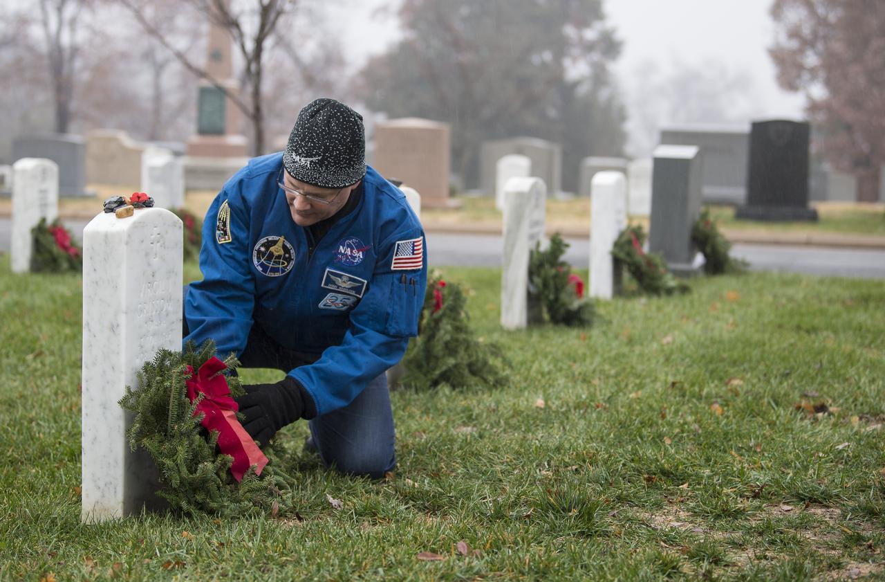
NASA astronaut Doug Wheelock lays a wreath at the grave marker of Virgil "Gus" Grissom from Apollo 1 as part of National Wreaths Across America Day, Sat., Dec. 14, 2019 at Arlington National Cemetery in Arlington, Va. National Wreaths Across America Day is held annually to celebrate the lives of military veterans and wreaths are placed at the foot of every headstone. Wheelock honored those who lost their lives in the quest for space exploration as well as fellow service members. Photo Credit: (NASA/Aubrey Gemignani)
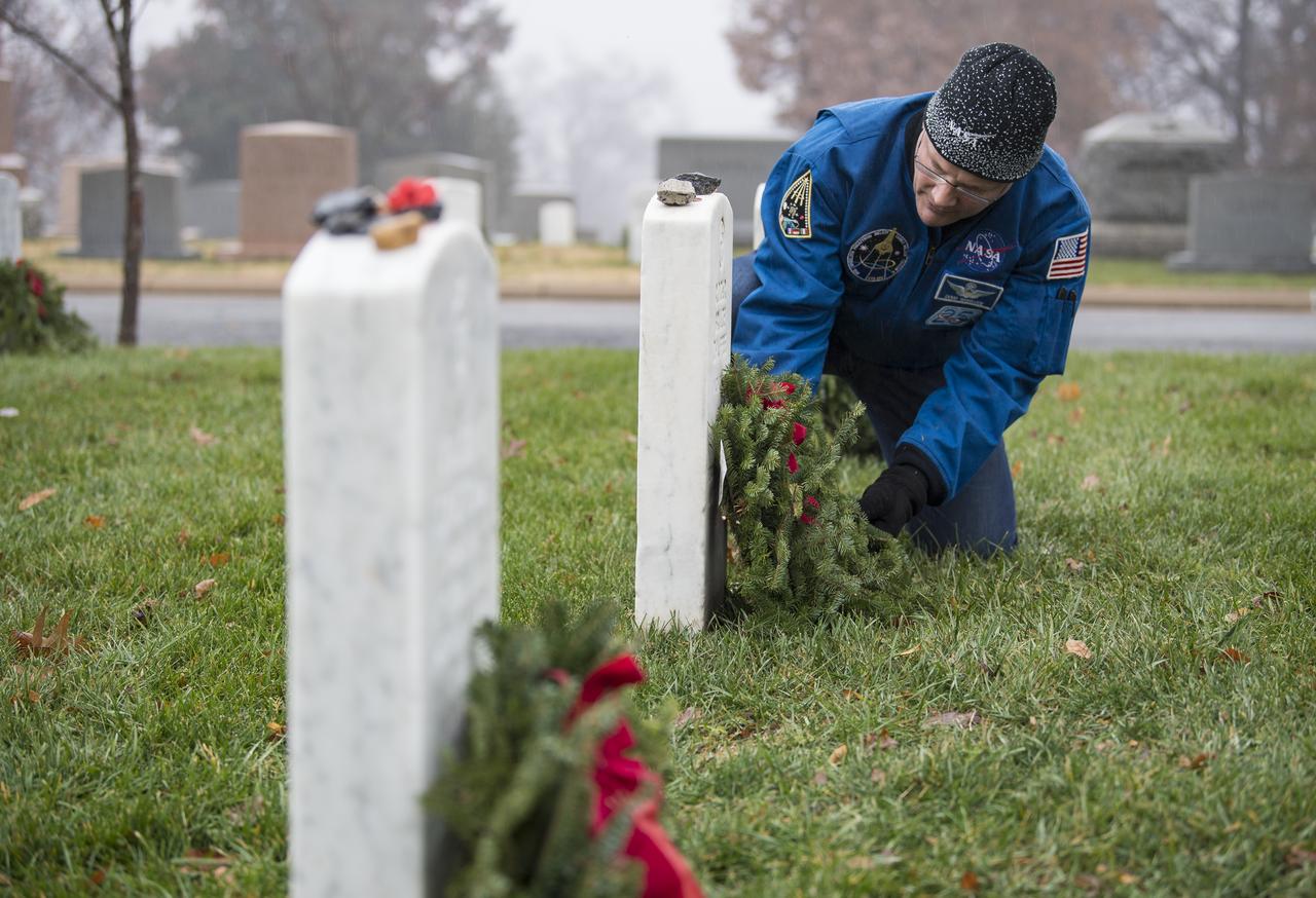
NASA astronaut Doug Wheelock lays a wreath at the grave marker of Roger Chaffee from Apollo 1 as part of National Wreaths Across America Day, Sat., Dec. 14, 2019 at Arlington National Cemetery in Arlington, Va. National Wreaths Across America Day is held annually to celebrate the lives of military veterans and wreaths are placed at the foot of every headstone. Wheelock honored those who lost their lives in the quest for space exploration as well as fellow service members. Photo Credit: (NASA/Aubrey Gemignani)
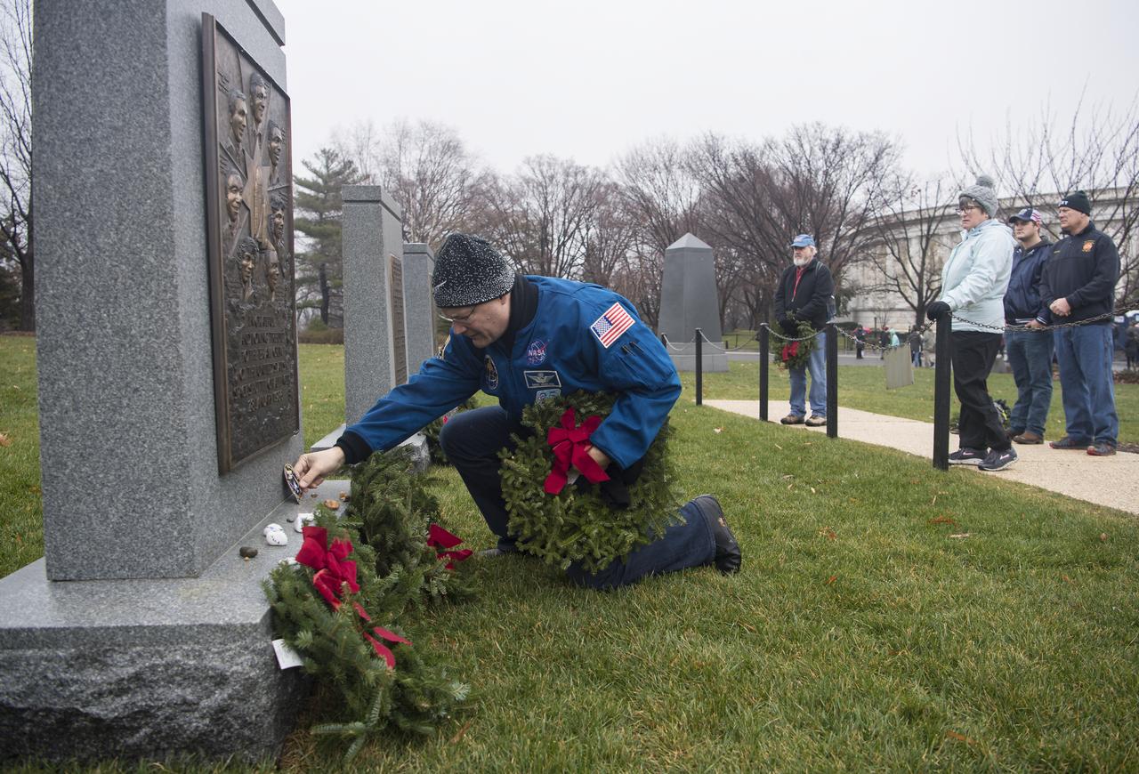
NASA astronaut Doug Wheelock leaves his STS-120 mission patch at the memorial for the Space Shuttle Challenger crew during National Wreaths Across America Day at Arlington National Cemetery, Sat., Dec. 14, 2019 in Arlington, Va. National Wreaths Across America Day is held annually to celebrate the lives of military veterans and wreaths are placed at the foot of every headstone. Wheelock honored those who lost their lives in the quest for space exploration as well as fellow service members. Photo Credit: (NASA/Aubrey Gemignani)

NASA astronaut Doug Wheelock lays a wreath at the gravesite of former astronaut and U.S. Senator John Glenn during National Wreaths Across America Day at Arlington National Cemetery, Sat., Dec. 14, 2019 in Arlington, Va. National Wreaths Across America Day is held annually to celebrate the lives of military veterans and wreaths are placed at the foot of every headstone. Wheelock honored those who lost their lives in the quest for space exploration as well as fellow service members. Photo Credit: (NASA/Aubrey Gemignani)
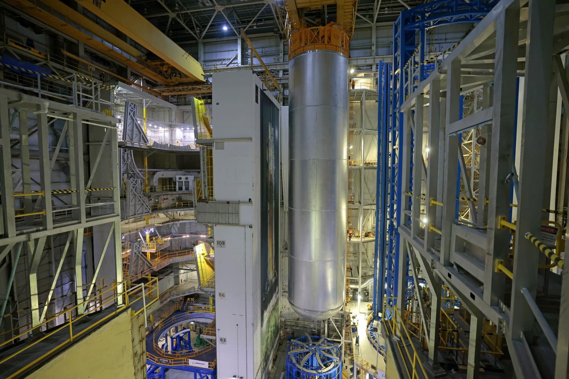
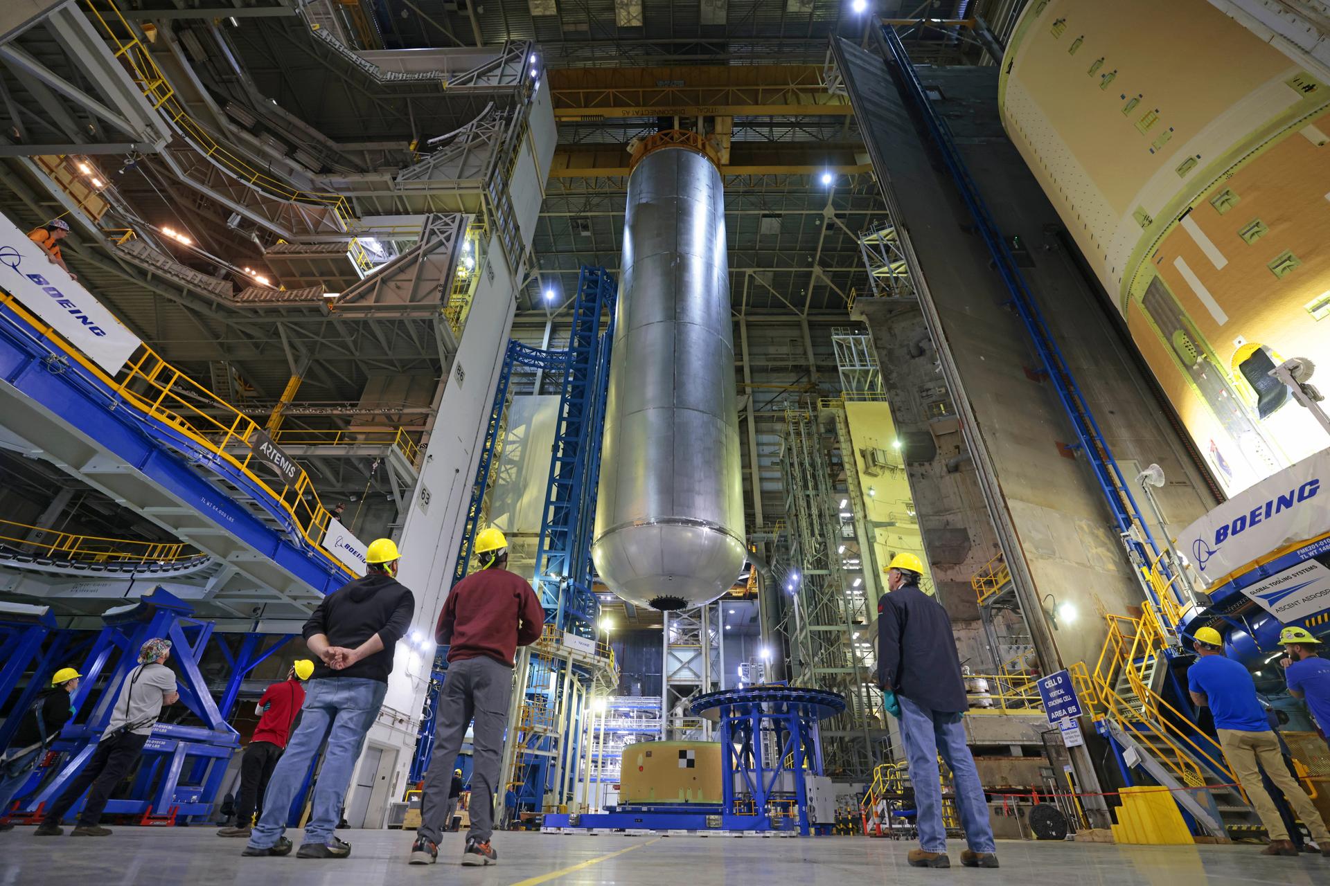
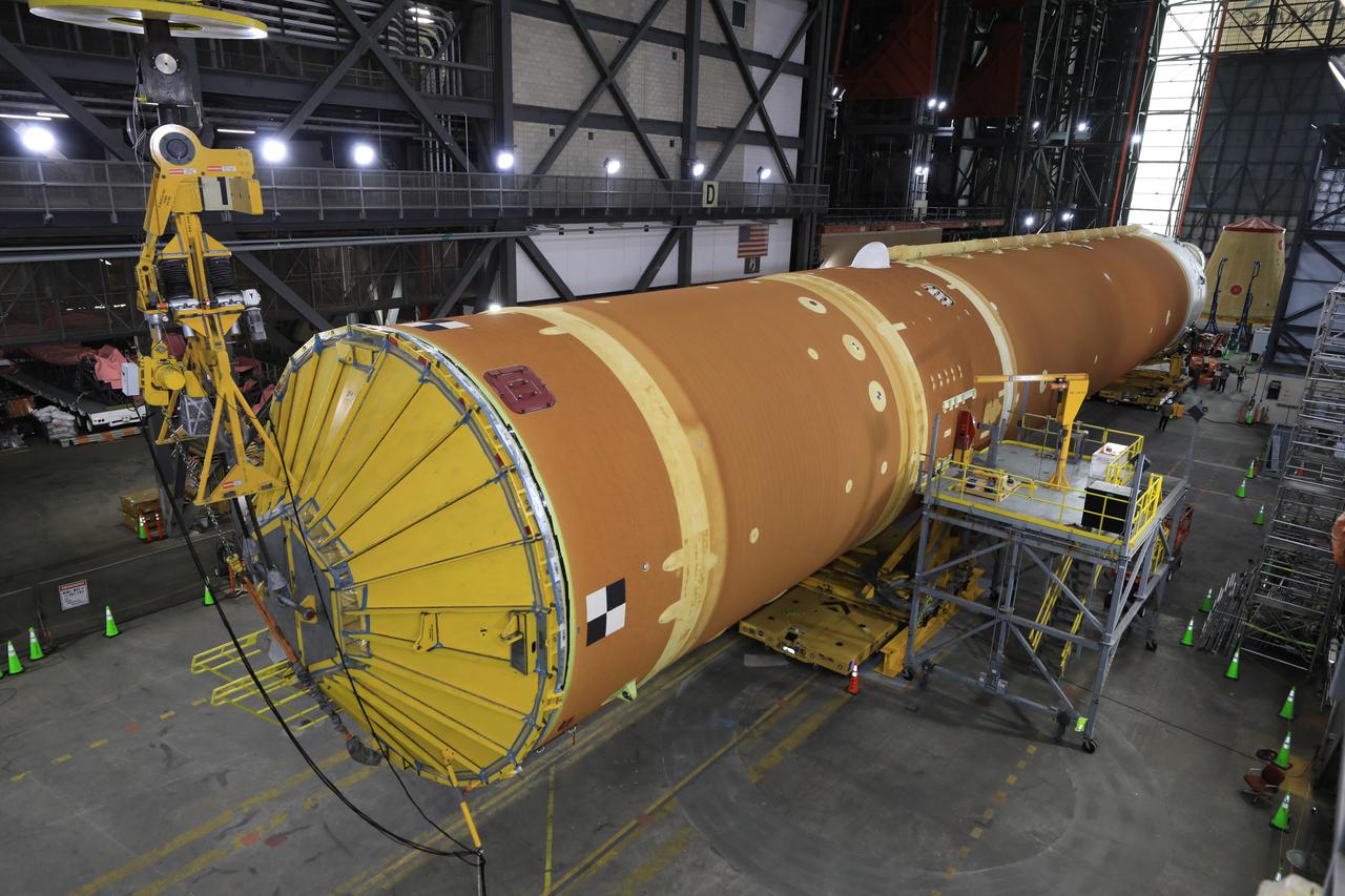
Teams at NASA’s Michoud Assembly Facility in New Orleans lift the 130-foot-tall liquid hydrogen tank off the vertical assembly center on Nov. 14. This is the fourth liquid hydrogen tank manufactured at the facility for the agency’s SLS (Space Launch System) rocket. The completed tank will be loaded into a production cell for technicians to remove the lift tool, perform dimensional scans, and then install brackets, which will allow the move crew to break the tank over from a vertical to a horizontal configuration.
Teams at NASA’s Michoud Assembly Facility in New Orleans lift the 130-foot-tall liquid hydrogen tank off the vertical assembly center on Nov. 14. This is the fourth liquid hydrogen tank manufactured at the facility for the agency’s SLS (Space Launch System) rocket. The completed tank will be loaded into a production cell for technicians to remove the lift tool, perform dimensional scans, and then install brackets, which will allow the move crew to break the tank over from a vertical to a horizontal configuration.
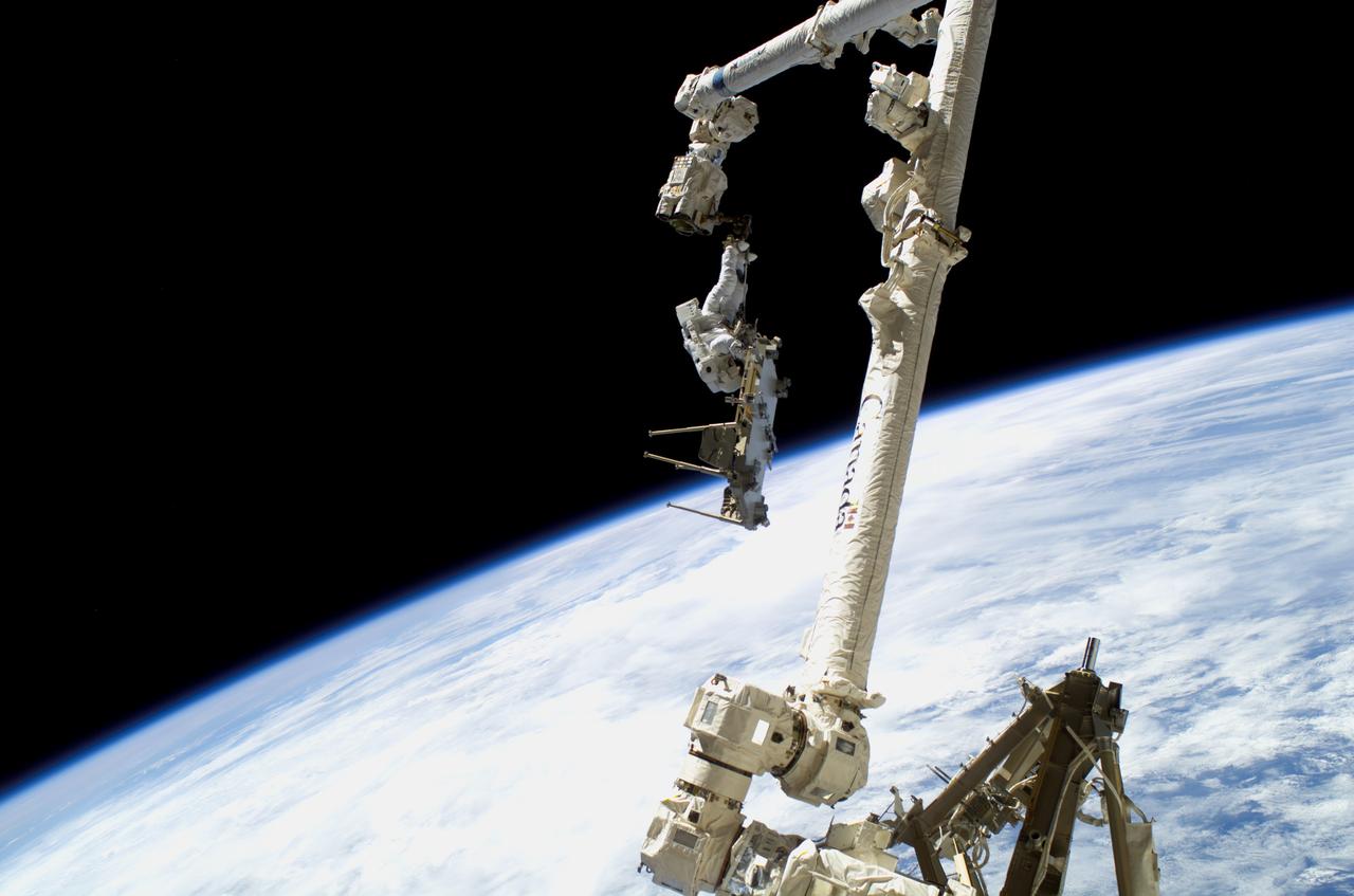
ISS014-E-09800 (14 Dec. 2006) --- Anchored to the International Space Station's Canadarm2 foot restraint, European Space Agency (ESA) astronaut Christer Fuglesang, STS-116 mission specialist, participates in the mission's second of three planned sessions of extravehicular activity (EVA) as construction resumes on the International Space Station. Astronaut Robert L. Curbeam, Jr. (out of frame), mission specialist, also participated in the spacewalk. The blackness of space and Earth's horizon provide the backdrop for the scene.
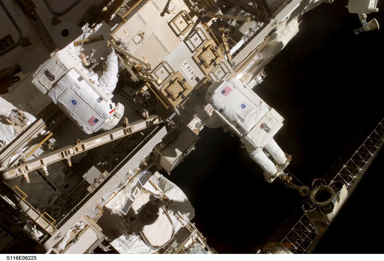
S116-E-06225 (14 Dec. 2006) --- Anchored to the International Space Station's Canadarm2 foot restraint, European Space Agency (ESA) astronaut Christer Fuglesang (right), STS-116 mission specialist, works in tandem with astronaut Robert L. Curbeam, Jr., mission specialist, during the mission's second of three planned sessions of extravehicular activity (EVA) as construction resumes on the station.

STS050-02-023 (25 June-9 July 1992) --- Astronaut Bonnie J. Dunbar, payload commander, unstows United States Microgravity Laboratory 1 (USML-1) experiment paraphernalia in early stages of the mission. The Multipurpose Glove Box (MPGB) is at upper left. And, at right center, is the Space Station design foot restraint, making its first flight aboard a Space Shuttle on the record-setting 14-day mission.
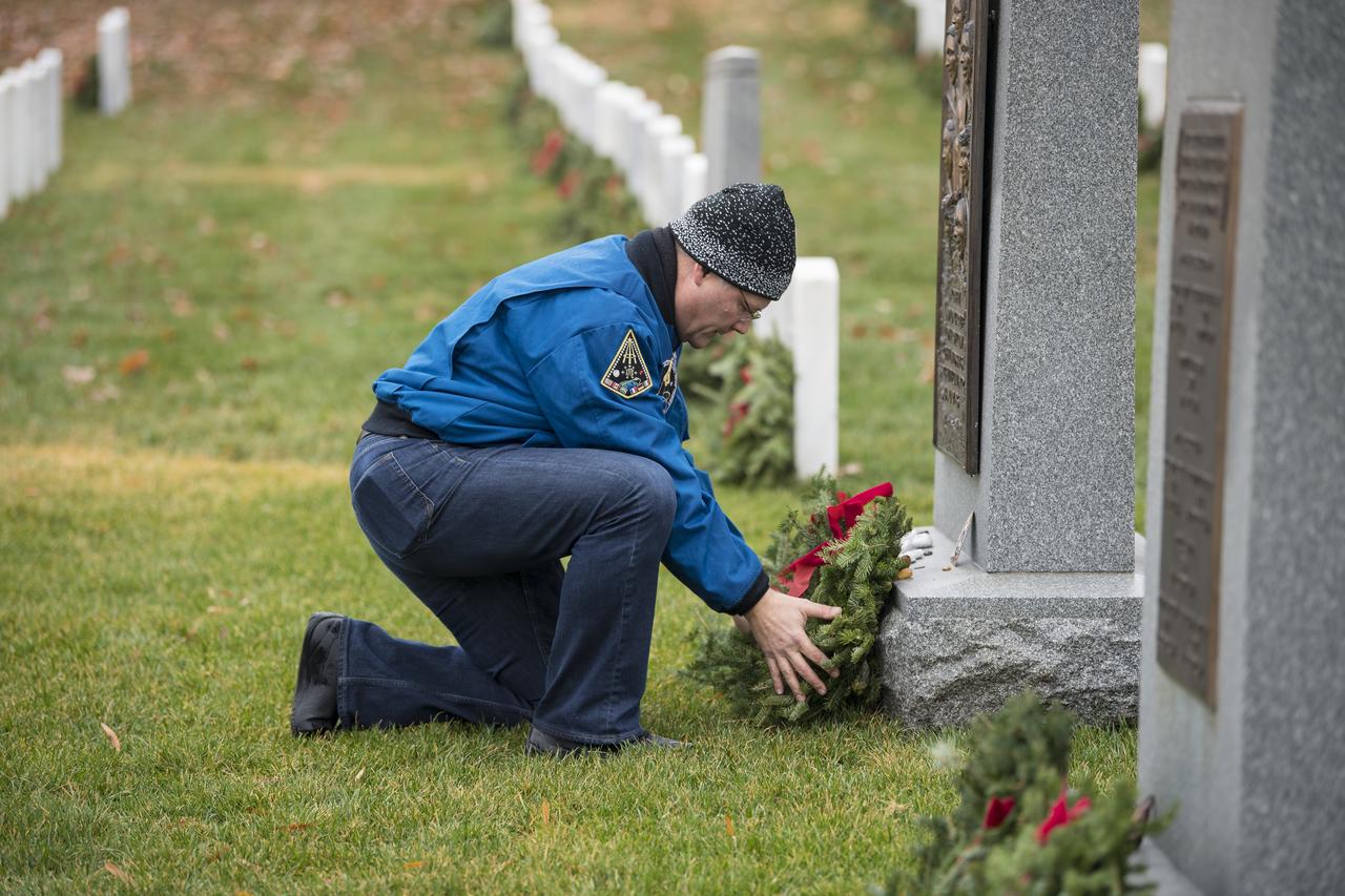
NASA astronaut Doug Wheelock lays a wreath at the memorial for the Space Shuttle Challenger crew during National Wreaths Across America Day at Arlington National Cemetery, Sat., Dec. 14, 2019 in Arlington, Va. National Wreaths Across America Day is held annually to celebrate the lives of military veterans and wreaths are placed at the foot of every headstone. Wheelock honored those who lost their lives in the quest for space exploration as well as fellow service members. Photo Credit: (NASA/Aubrey Gemignani)

51A-39-040 (14 Nov. 1984) --- A 70mm frame of Westar VI retrieval. Astronauts Dale A. Gardner, left, and Joseph P. Allen IV work together with Anna L. Fisher (not pictured, controlling remote manipulator system (RMS) arm from Discovery?s cabin) to bring Westar VI/PAM-D into cargo bay. Allen is on the mobile foot restraint, which is attached to the RMS end effector, while Gardner works to remove a stinger device from the now stabilized satellite. Photo credit: NASA
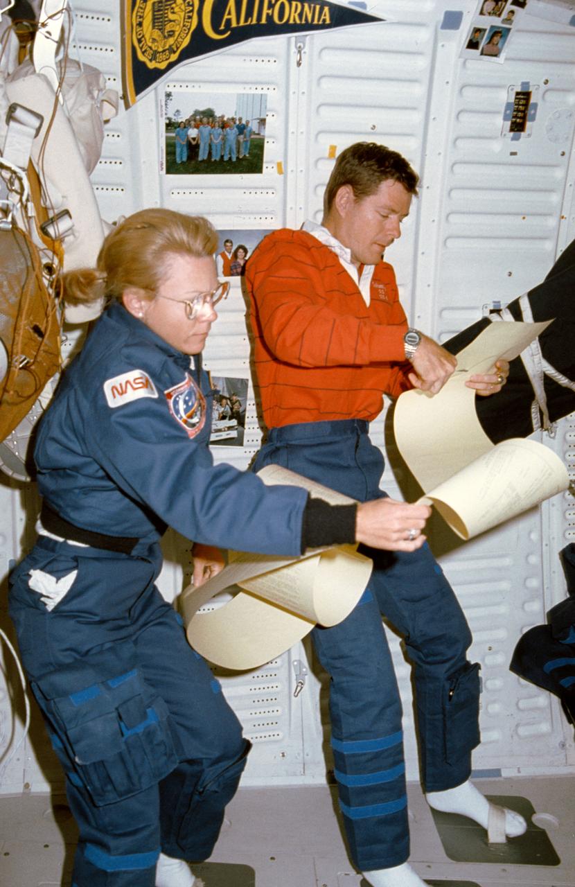
STS040-17-003 (5-14 June 1991) --- Astronauts Rhea Seddon and Bryan D. O'Connor share a 15 ft. length of teleprinter messages aboard Columbia. During the nine-day Spacelab Life Sciences (SLS-1) mission, the STS-40 crewmembers received a large volume of similar print-outs from ground controllers. Using foot restraints, the two obviously expect their perusing to take awhile. This middeck scene was photographed with a 35mm camera.

On the left is a radar image of asteroid 1998 WT24 taken in December 2001 by scientists using NASA's the 230-foot (70-meter) DSS-14 antenna at Goldstone, California. On the right is a radar image of the same asteroid acquired on Dec. 11, 2015, during the asteroid's most recent Earth flyby. The radar images from 2001 (on the left), have a resolution of about 60 feet (19 meters) per pixel. The radar image from 2015 (on the right) achieved a spatial resolution as fine as 25 feet (7.5 meters) per pixel. The 2015 radar image was obtained using the same DSS-14 antenna at Goldstone to transmit high-power microwaves toward the asteroid. However, this time, the radar echoes bounced off the asteroid were received by the National Radio Astronomy Observatory's 100-meter (330-foot) Green Bank Telescope in West Virginia. The next visit of asteroid 1998 WT24 to Earth's neighborhood will be on Nov. 11, 2018, when it will make a distant pass at about 12.5-million miles (52 lunar distances). http://photojournal.jpl.nasa.gov/catalog/PIA20216
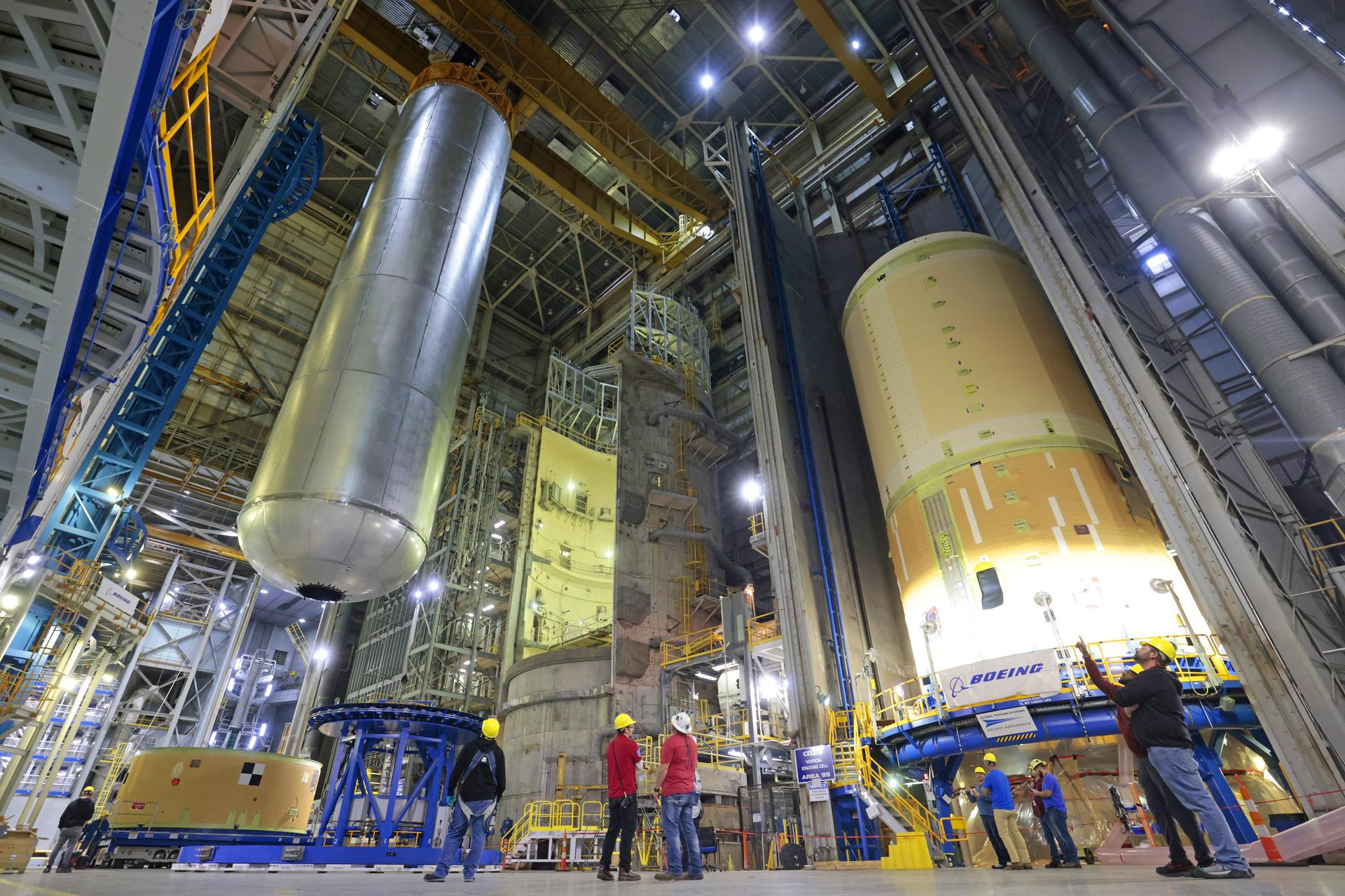
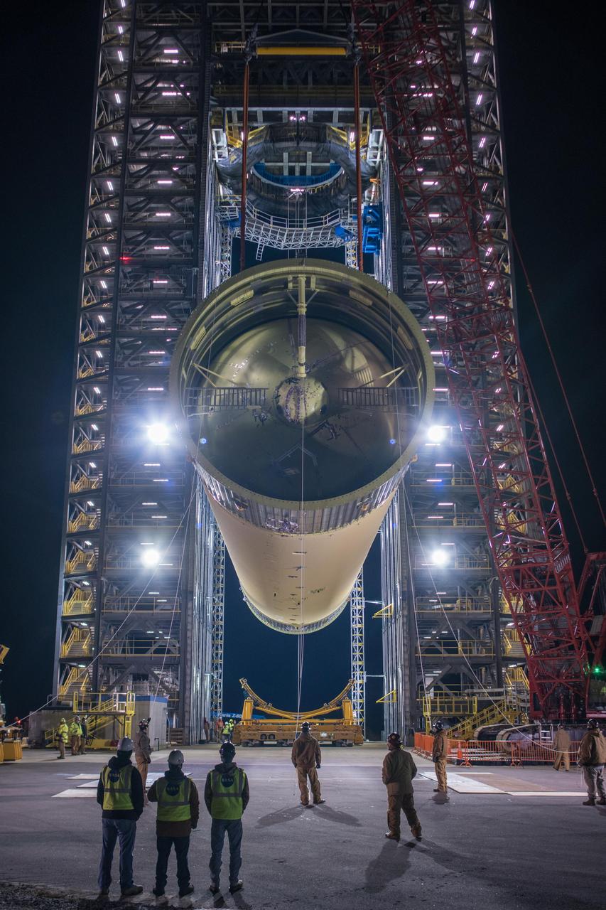
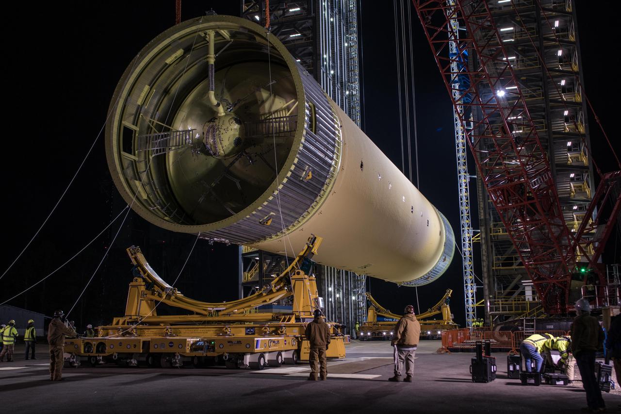
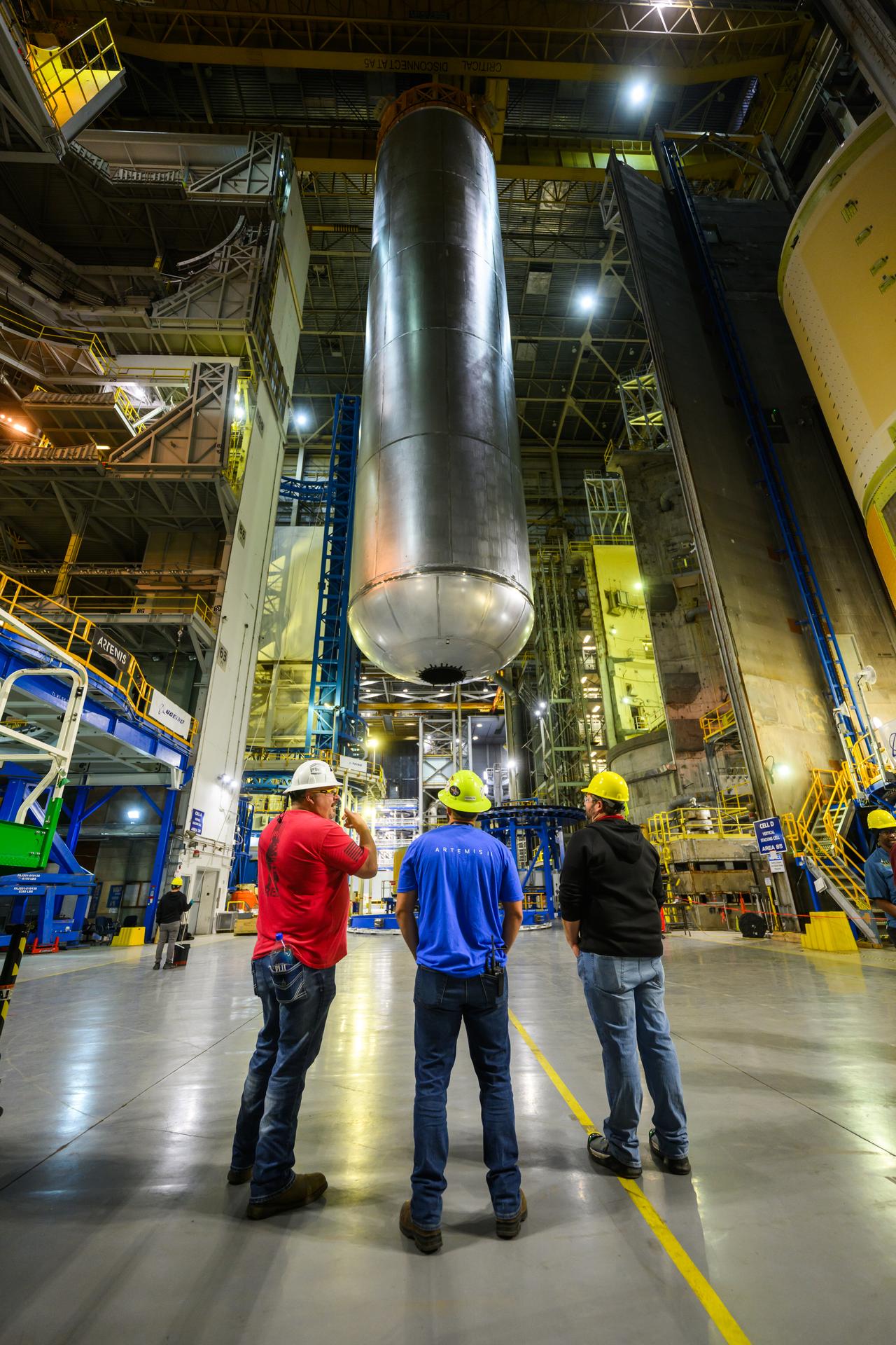
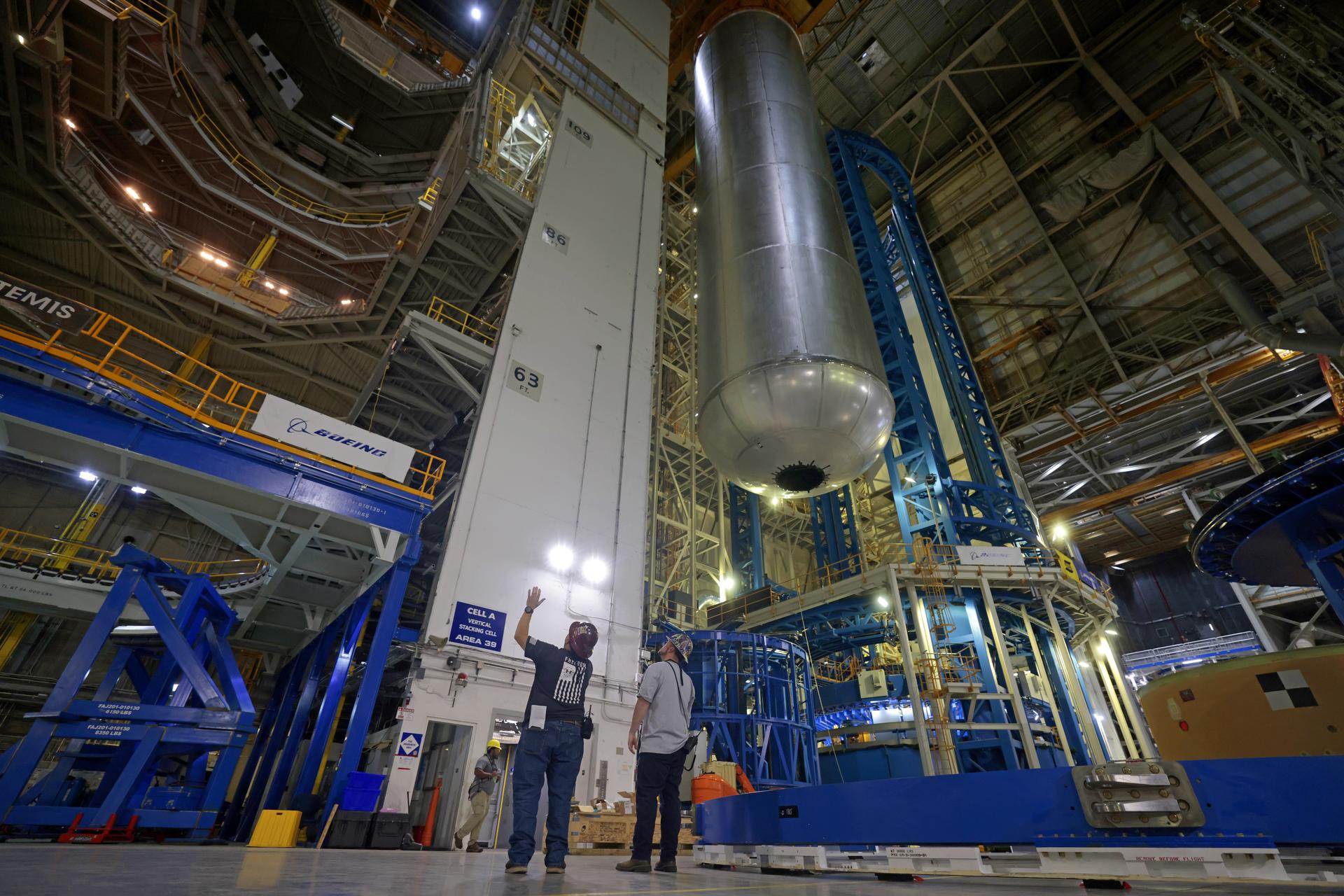
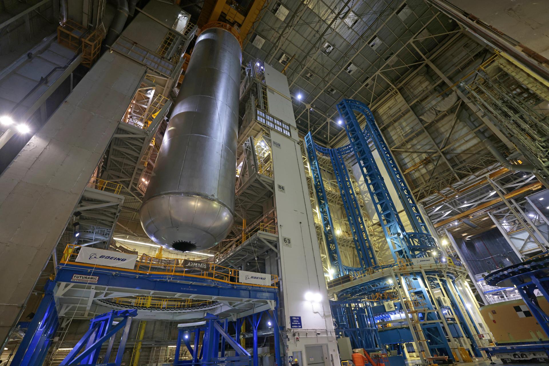
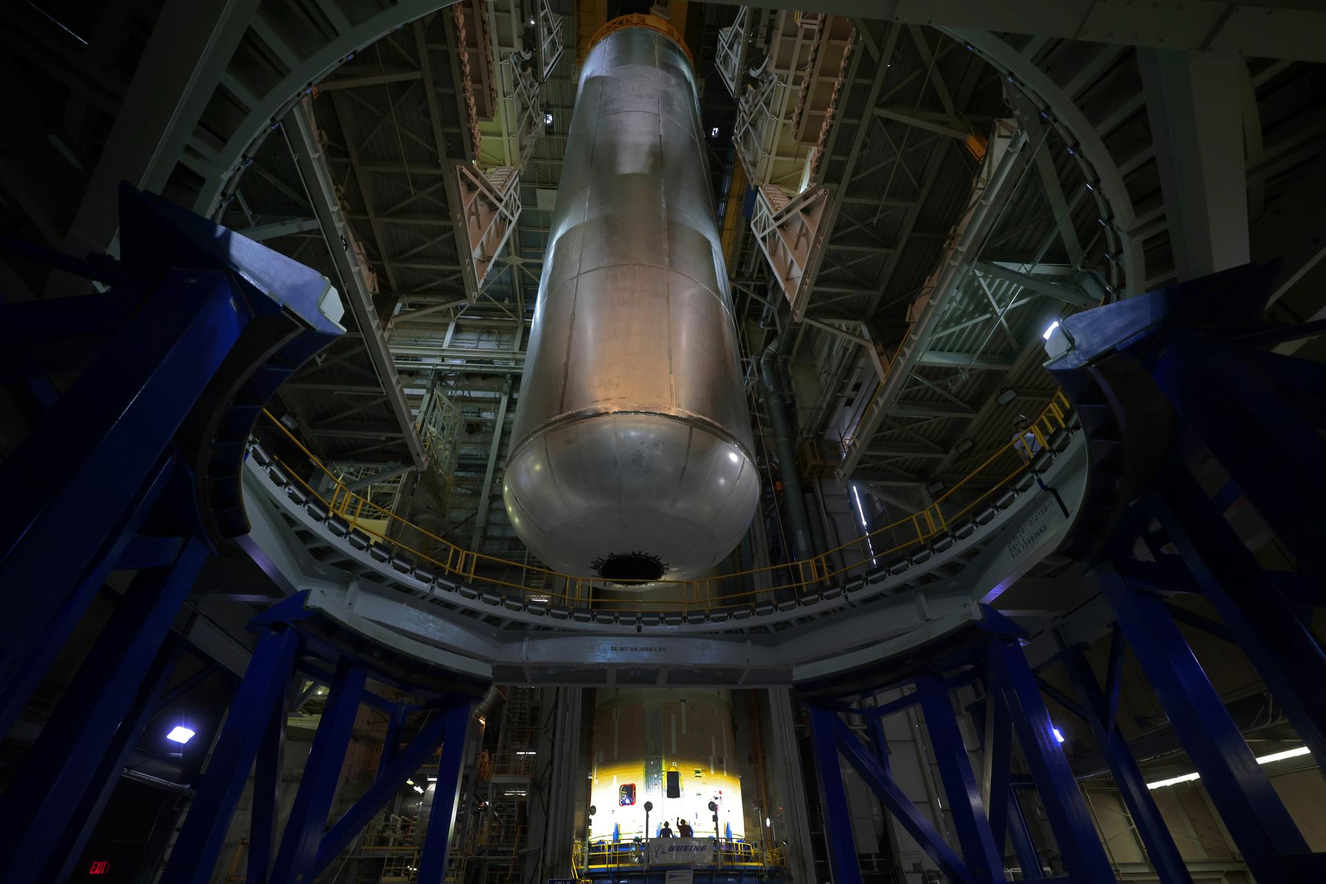
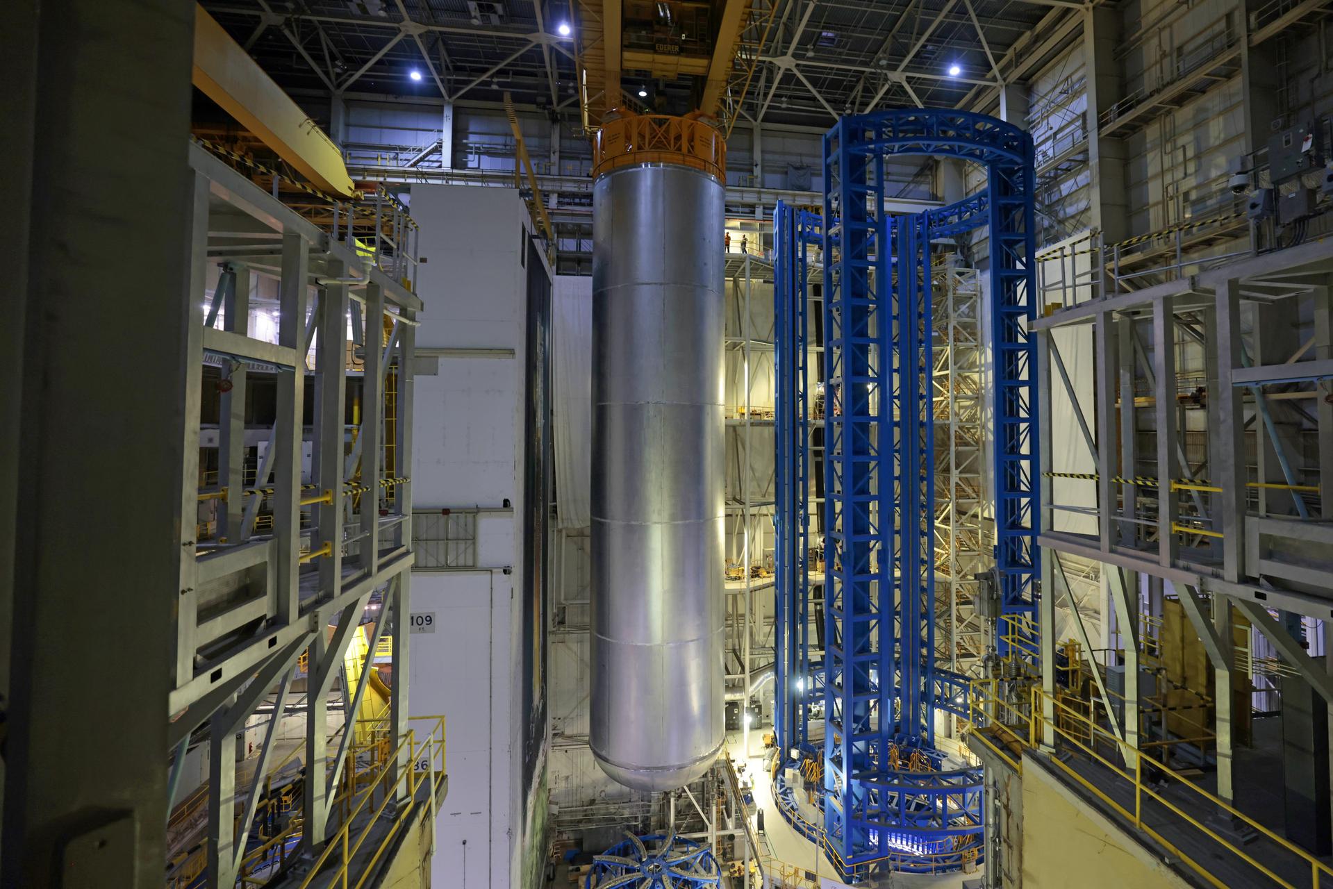
Teams at NASA’s Michoud Assembly Facility in New Orleans lift the 130-foot-tall liquid hydrogen tank off the vertical assembly center on Nov. 14. This is the fourth liquid hydrogen tank manufactured at the facility for the agency’s SLS (Space Launch System) rocket. The completed tank will be loaded into a production cell for technicians to remove the lift tool, perform dimensional scans, and then install brackets, which will allow the move crew to break the tank over from a vertical to a horizontal configuration. The propellant tank is one of five major elements that make up the 212-foot-tall rocket stage. The core stage, along with its four RS-25 engines, produce more than two million pounds of thrust to help launch NASA’s Orion spacecraft, astronauts, and supplies beyond Earth’s orbit and to the lunar surface for Artemis. Image credit: NASA/Michael DeMocker
Teams at NASA’s Michoud Assembly Facility in New Orleans lift the 130-foot-tall liquid hydrogen tank off the vertical assembly center on Nov. 14. This is the fourth liquid hydrogen tank manufactured at the facility for the agency’s SLS (Space Launch System) rocket. The completed tank will be loaded into a production cell for technicians to remove the lift tool, perform dimensional scans, and then install brackets, which will allow the move crew to break the tank over from a vertical to a horizontal configuration. The propellant tank is one of five major elements that make up the 212-foot-tall rocket stage. The core stage, along with its four RS-25 engines, produce more than two million pounds of thrust to help launch NASA’s Orion spacecraft, astronauts, and supplies beyond Earth’s orbit and to the lunar surface for Artemis. Image credit: NASA/Michael DeMocker
Teams at NASA’s Michoud Assembly Facility in New Orleans lift the 130-foot-tall liquid hydrogen tank off the vertical assembly center on Nov. 14. This is the fourth liquid hydrogen tank manufactured at the facility for the agency’s SLS (Space Launch System) rocket. The completed tank will be loaded into a production cell for technicians to remove the lift tool, perform dimensional scans, and then install brackets, which will allow the move crew to break the tank over from a vertical to a horizontal configuration. The propellant tank is one of five major elements that make up the 212-foot-tall rocket stage. The core stage, along with its four RS-25 engines, produce more than two million pounds of thrust to help launch NASA’s Orion spacecraft, astronauts, and supplies beyond Earth’s orbit and to the lunar surface for Artemis. Image credit: NASA/Michael DeMocker
Teams at NASA’s Michoud Assembly Facility in New Orleans lift the 130-foot-tall liquid hydrogen tank off the vertical assembly center on Nov. 14. This is the fourth liquid hydrogen tank manufactured at the facility for the agency’s SLS (Space Launch System) rocket. The completed tank will be loaded into a production cell for technicians to remove the lift tool, perform dimensional scans, and then install brackets, which will allow the move crew to break the tank over from a vertical to a horizontal configuration. The propellant tank is one of five major elements that make up the 212-foot-tall rocket stage. The core stage, along with its four RS-25 engines, produce more than two million pounds of thrust to help launch NASA’s Orion spacecraft, astronauts, and supplies beyond Earth’s orbit and to the lunar surface for Artemis. Image credit: NASA/Michael DeMocker
Teams at NASA’s Michoud Assembly Facility in New Orleans lift the 130-foot-tall liquid hydrogen tank off the vertical assembly center on Nov. 14. This is the fourth liquid hydrogen tank manufactured at the facility for the agency’s SLS (Space Launch System) rocket. The completed tank will be loaded into a production cell for technicians to remove the lift tool, perform dimensional scans, and then install brackets, which will allow the move crew to break the tank over from a vertical to a horizontal configuration. The propellant tank is one of five major elements that make up the 212-foot-tall rocket stage. The core stage, along with its four RS-25 engines, produce more than two million pounds of thrust to help launch NASA’s Orion spacecraft, astronauts, and supplies beyond Earth’s orbit and to the lunar surface for Artemis. Image credit: NASA/Michael DeMocker
Teams at NASA’s Michoud Assembly Facility in New Orleans lift the 130-foot-tall liquid hydrogen tank off the vertical assembly center on Nov. 14. This is the fourth liquid hydrogen tank manufactured at the facility for the agency’s SLS (Space Launch System) rocket. The completed tank will be loaded into a production cell for technicians to remove the lift tool, perform dimensional scans, and then install brackets, which will allow the move crew to break the tank over from a vertical to a horizontal configuration. The propellant tank is one of five major elements that make up the 212-foot-tall rocket stage. The core stage, along with its four RS-25 engines, produce more than two million pounds of thrust to help launch NASA’s Orion spacecraft, astronauts, and supplies beyond Earth’s orbit and to the lunar surface for Artemis. Image credit: NASA/Michael DeMocker
Teams at NASA’s Michoud Assembly Facility in New Orleans lift the 130-foot-tall liquid hydrogen tank off the vertical assembly center on Nov. 14. This is the fourth liquid hydrogen tank manufactured at the facility for the agency’s SLS (Space Launch System) rocket. The completed tank will be loaded into a production cell for technicians to remove the lift tool, perform dimensional scans, and then install brackets, which will allow the move crew to break the tank over from a vertical to a horizontal configuration. The propellant tank is one of five major elements that make up the 212-foot-tall rocket stage. The core stage, along with its four RS-25 engines, produce more than two million pounds of thrust to help launch NASA’s Orion spacecraft, astronauts, and supplies beyond Earth’s orbit and to the lunar surface for Artemis. Image credit: NASA/Michael DeMocker
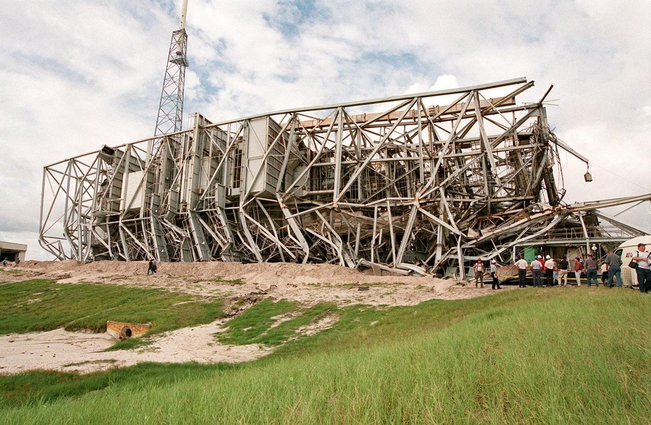
KENNEDY SPACE CENTER, FLA. -- The fallen 300-foot, five-million-pound Mobile Service Tower (MST) on Launch Complex 41, Cape Canaveral Air Force Station, looms over the head of a worker on the ground beside it. The MST and a 200-foot-high umbilical tower nearby were demolished to make room for Lockheed Martin's 14-acre Vehicle Integration Facility (VIF), under construction. Only lightning protection towers, such as the one seen behind the MST, remain standing at the site. About 200 pounds of linear-shaped charges were used to bring down the towers so that the materials can be recycled. The implosion and removal of the tower debris is expected to be completed in two months. The VIF will be used for Lockheed Martin's Atlas V Launch System.
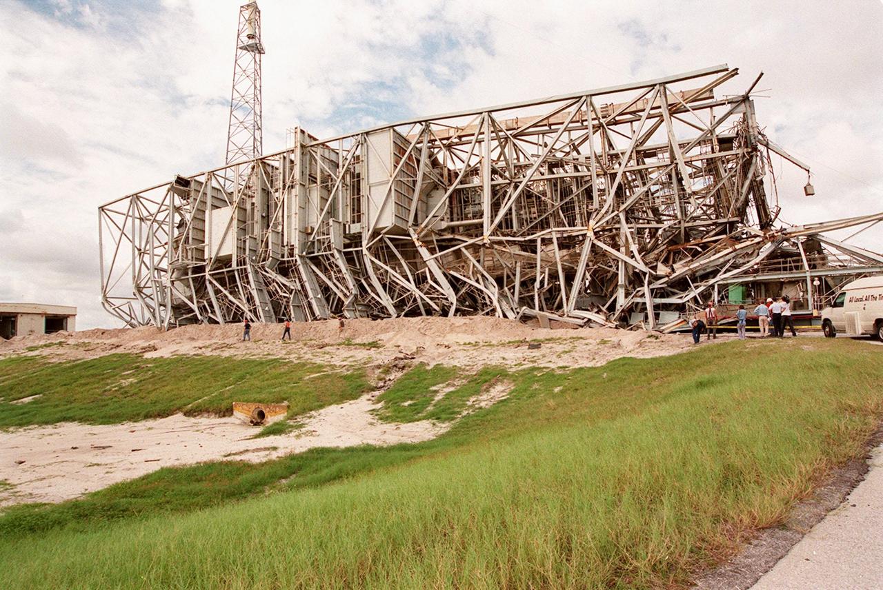
KENNEDY SPACE CENTER, FLA. -- The 300-foot, five-million-pound Mobile Service Tower (MST) on Launch Complex 41, Cape Canaveral Air Force Station, lies on its side after being demolished. The MST and a 200-foot-high umbilical tower nearby were demolished to make room for Lockheed Martin's 14-acre Vehicle Integration Facility (VIF), under construction. Only lightning protection towers, such as the one seen behind the MST, remain standing at the site. About 200 pounds of linear-shaped charges were used to bring down the towers so that the materials can be recycled. The implosion and removal of the tower debris is expected to be completed in two months. The VIF will be used for Lockheed Martin's Atlas V Launch System.
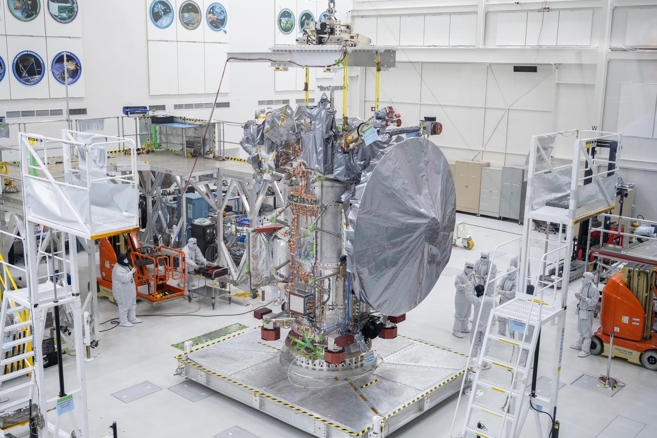
NASA's Europa Clipper spacecraft boasts its new 10-foot (3-meter) high-gain antenna, after its Aug. 14, 2023, installation in High Bay 1 of the Spacecraft Assembly Facility at the agency's Jet Propulsion Laboratory in Southern California. The orbiter is being assembled in preparation for launch to Jupiter's moon Europa in October 2024. The precision-engineered dish was attached to the spacecraft in carefully choreographed stages over the course of several hours. Europa Clipper will need the huge antenna to transmit data hundreds of millions of miles back to Earth. Scientists believe the icy moon Europa harbors a vast internal ocean that may have conditions suitable for supporting life. The spacecraft will fly by the moon about 50 times while its science instruments gather data on the moon's atmosphere, surface, and interior – information that will help scientists learn more about the ocean, the ice crust, and potential plumes that may be venting subsurface water into space. https://photojournal.jpl.nasa.gov/catalog/PIA25958
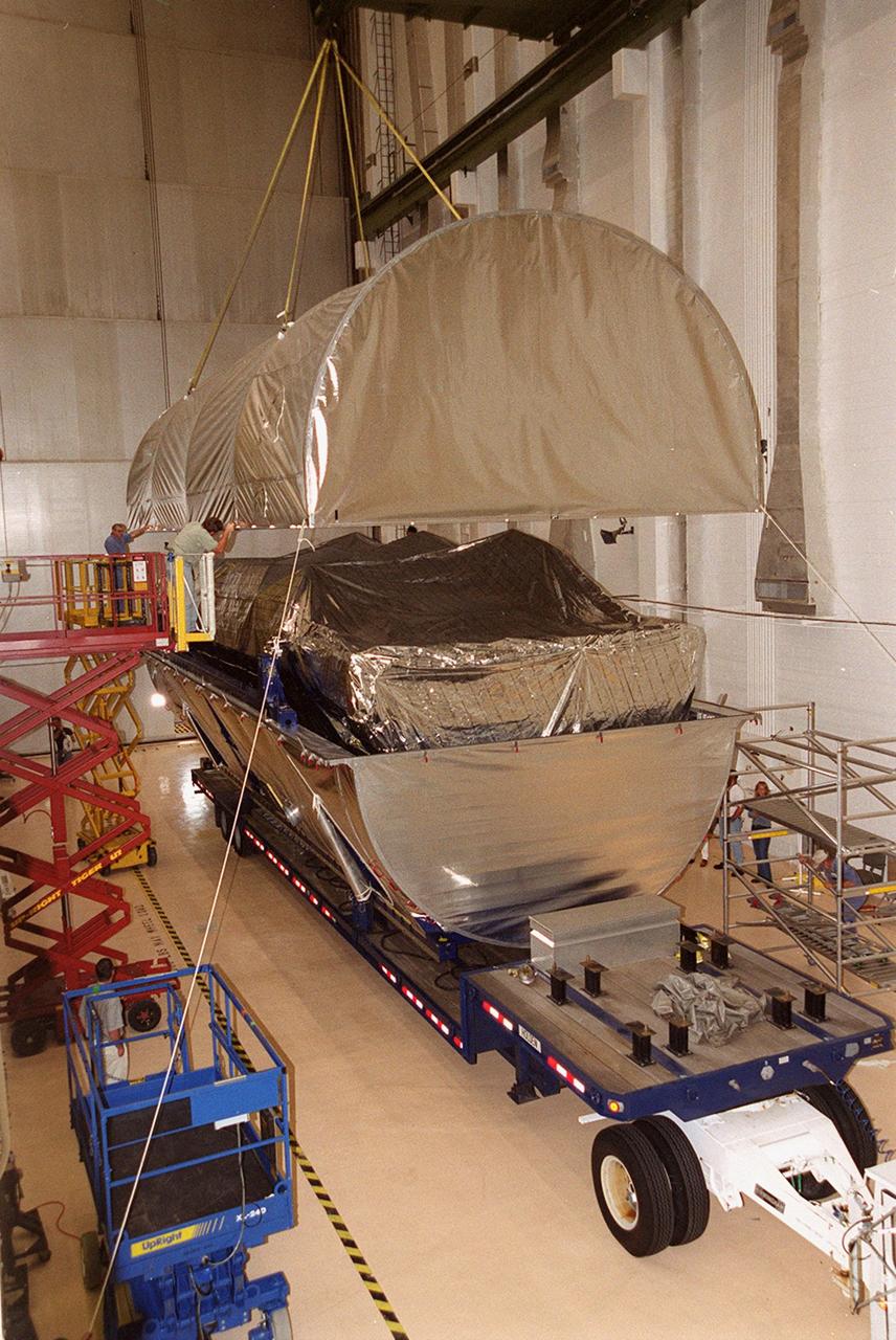
Workers oversee the placement of the P-1 truss, a component of the International Space Station, onto a flatbed truck that will move it to the Operations and Checkout Building for processing. The P-1 truss, scheduled to fly in spring of 2002, is part of a total 10-truss, girder-like structure on the Station that will ultimately extend the length of a football field. Astronauts will attach the 14-by-15 foot structure to the port side of the center truss, S0, during the spring assembly flight. The 33,000-pound P-1 will house the thermal radiator rotating joint (TRRJ) that will rotate the Station’s radiators away from the sun to increase their maximum cooling efficiency
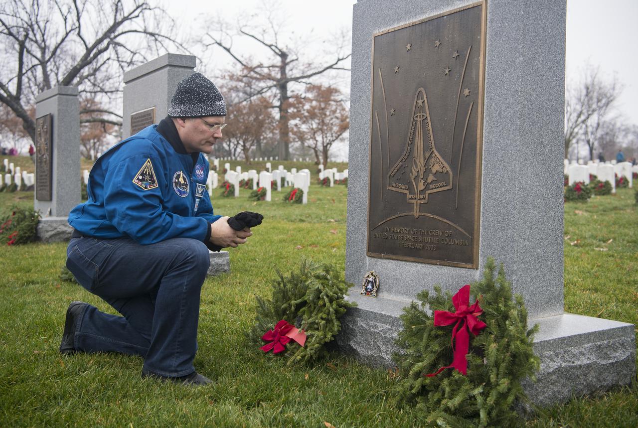
NASA astronaut Doug Wheelock takes a moment after leaving his STS-120 mission patch at the memorial for the Space Shuttle Columbia crew during National Wreaths Across America Day at Arlington National Cemetery, Sat., Dec. 14, 2019 in Arlington, Va. National Wreaths Across America Day is held annually to celebrate the lives of military veterans and wreaths are placed at the foot of every headstone. Wheelock honored those who lost their lives in the quest for space exploration as well as fellow service members. Photo Credit: (NASA/Aubrey Gemignani)

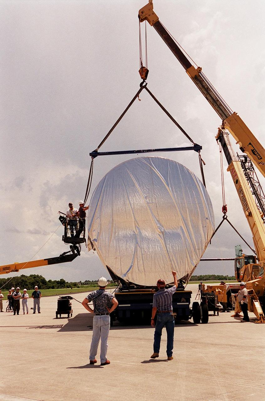
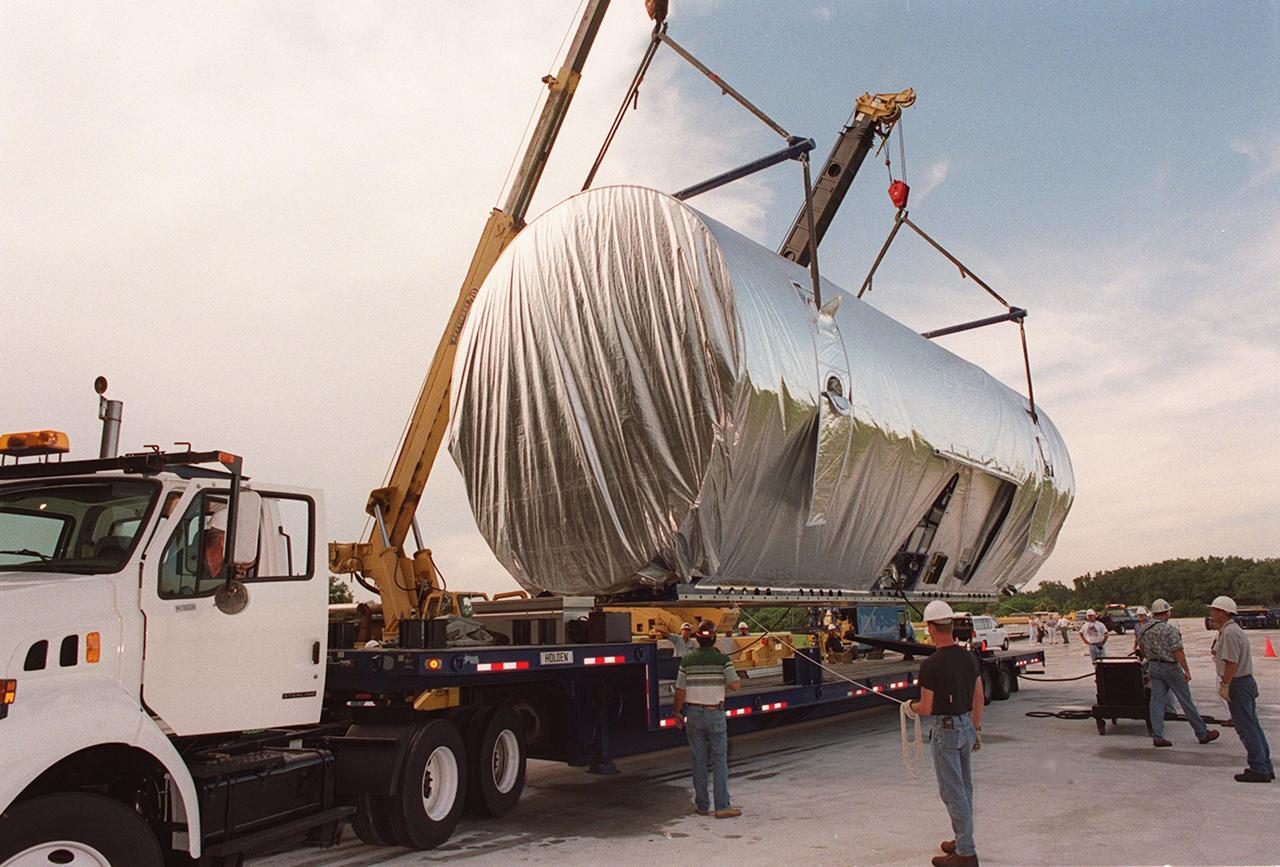
On July 26, 2000 the P-1 truss arrived at Kennedy Space Center’s Shuttle Landing Facility aboard its "Super Guppy" transport. The P-1 truss, scheduled to fly in spring of 2002, is part of a total 10-truss, girder-like structure that will ultimately extend the length of a football field. Astronauts will attach the 14-by-15 foot structure to the port side of the center truss, SO, during the spring assembly flight. The 33,000-pound P-1 will house the thermal radiator rotating joint (TRRJ) that will rotate the International Space Station’s radiators away from the sun to increase their maximum cooling efficiency
The P-1 truss (top of photo), a component of the International Space Station, nears its work stand in the Operations and Checkout Building where it will undergo processing. Scheduled to fly in spring of 2002, the P-1 is part of a total 10-truss, girder-like structure on the Station that will ultimately extend the length of a football field. Astronauts will attach the 14-by-15 foot structure to the port side of the center truss, S0, during the spring assembly flight. The 33,000-pound P-1 will house the thermal radiator rotating joint (TRRJ) that will rotate the Station’s radiators away from the sun to increase their maximum cooling efficiency
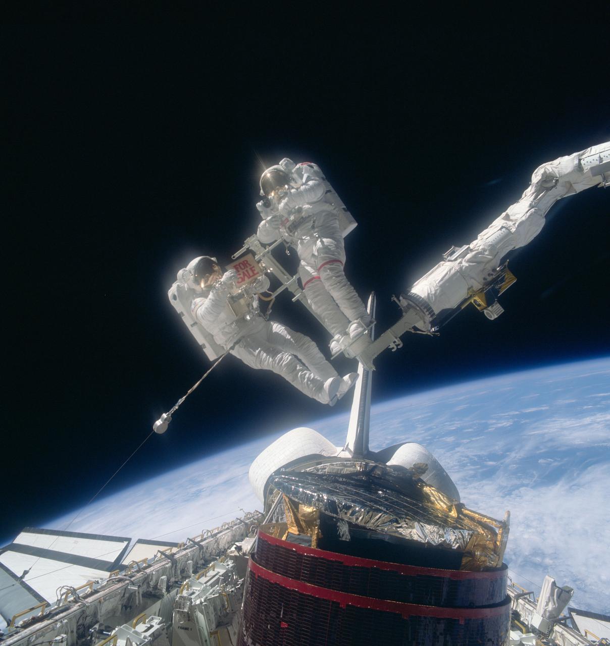
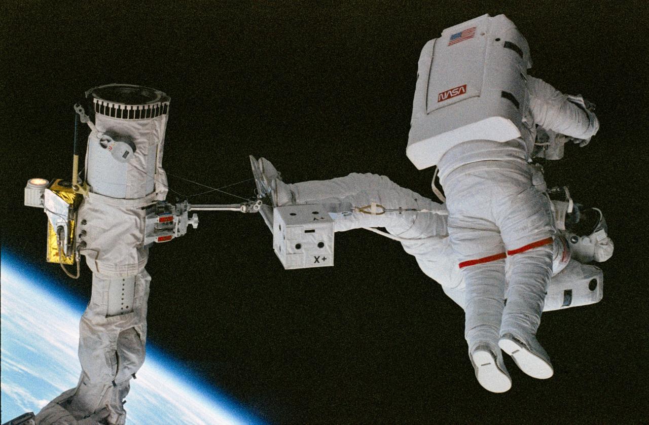
51A-39-063 (14 Nov 1984) --- A 70mm frame of WESTAR VI post-retrieval activity. Astronaut Dale A. Gardner (left), STS-51A mission specialist, holds a "For Sale" sign, making light reference to the status of the re-captured communications spacecraft, which has been stranded since its initial deployment. Astronaut Joseph P. Allen IV stands on the Mobile Foot Restraint (MFR), which in tandem with the Remote Manipulator System (RMS) arm, controlled by Dr. Anna L. Fisher inside the space shuttle Discovery's cabin, served as a cherry-picker for capture efforts. Photo credit: NASA
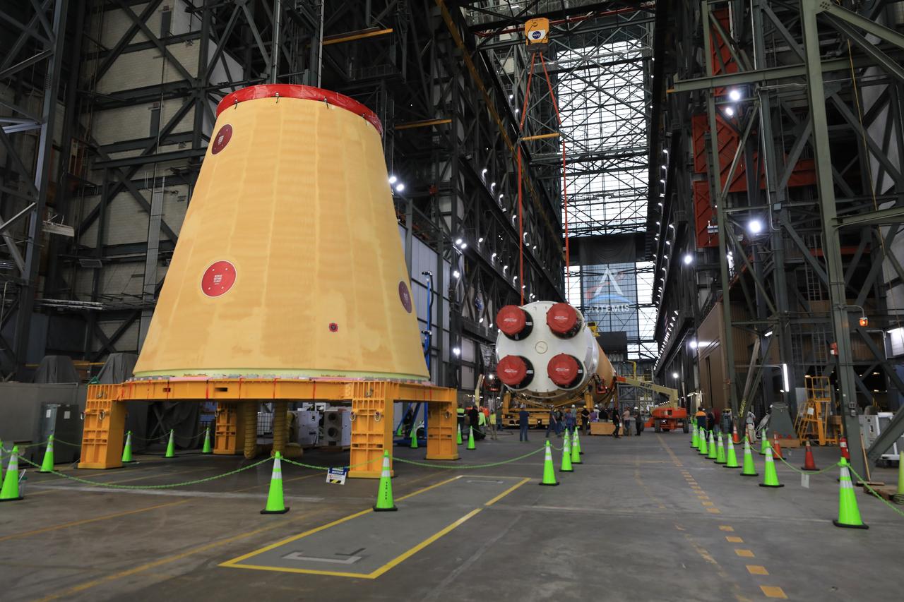
Technicians from NASA’s Exploration Ground Systems use massive cranes inside the agency’s Vehicle Assembly Building (VAB) to lift the fully assembled SLS (Space Launch System) core stage vertically 225 feet above the ground from High Bay 2 to a horizontal position in the facility’s transfer aisle at NASA’s Kennedy Space Center in Florida on Friday, March 14, 2025. The 212-foot core stage will undergo final checkouts before being lifted into the VAB’s High Bay 3 for integration alongside the completed stack of twin solid rocket booster segments.
Technicians from NASA’s Exploration Ground Systems use massive cranes inside the agency’s Vehicle Assembly Building (VAB) to lift the fully assembled SLS (Space Launch System) core stage vertically 225 feet above the ground from High Bay 2 to a horizontal position in the facility’s transfer aisle at NASA’s Kennedy Space Center in Florida on Friday, March 14, 2025. The 212-foot core stage will undergo final checkouts before being lifted into the VAB’s High Bay 3 for integration alongside the completed stack of twin solid rocket booster segments.
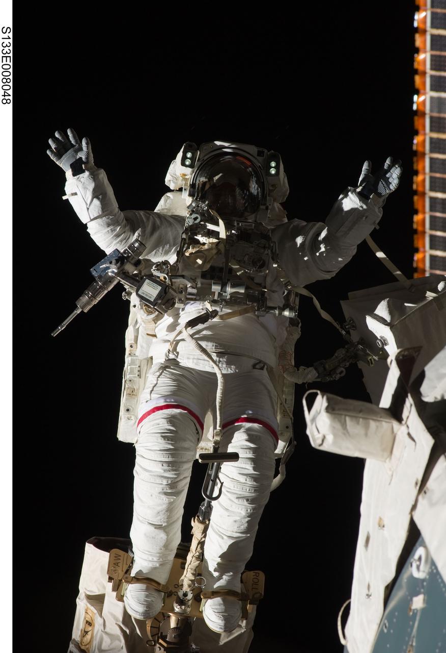
S133-E-008048 (2 March 2011) --- Anchored to a Canadarm2 mobile foot restraint, NASA astronaut Steve Bowen, STS-133 mission specialist, participates in the mission’s second session of extravehicular activity (EVA) as construction and maintenance continue on the International Space Station. During the six-hour, 14-minute spacewalk, Bowen and astronaut Alvin Drew (out of frame), mission specialist, tackled a variety of tasks, including venting into space some remaining ammonia from a failed pump module they moved during the mission’s first spacewalk. Photo credit: NASA or National Aeronautics and Space Administration
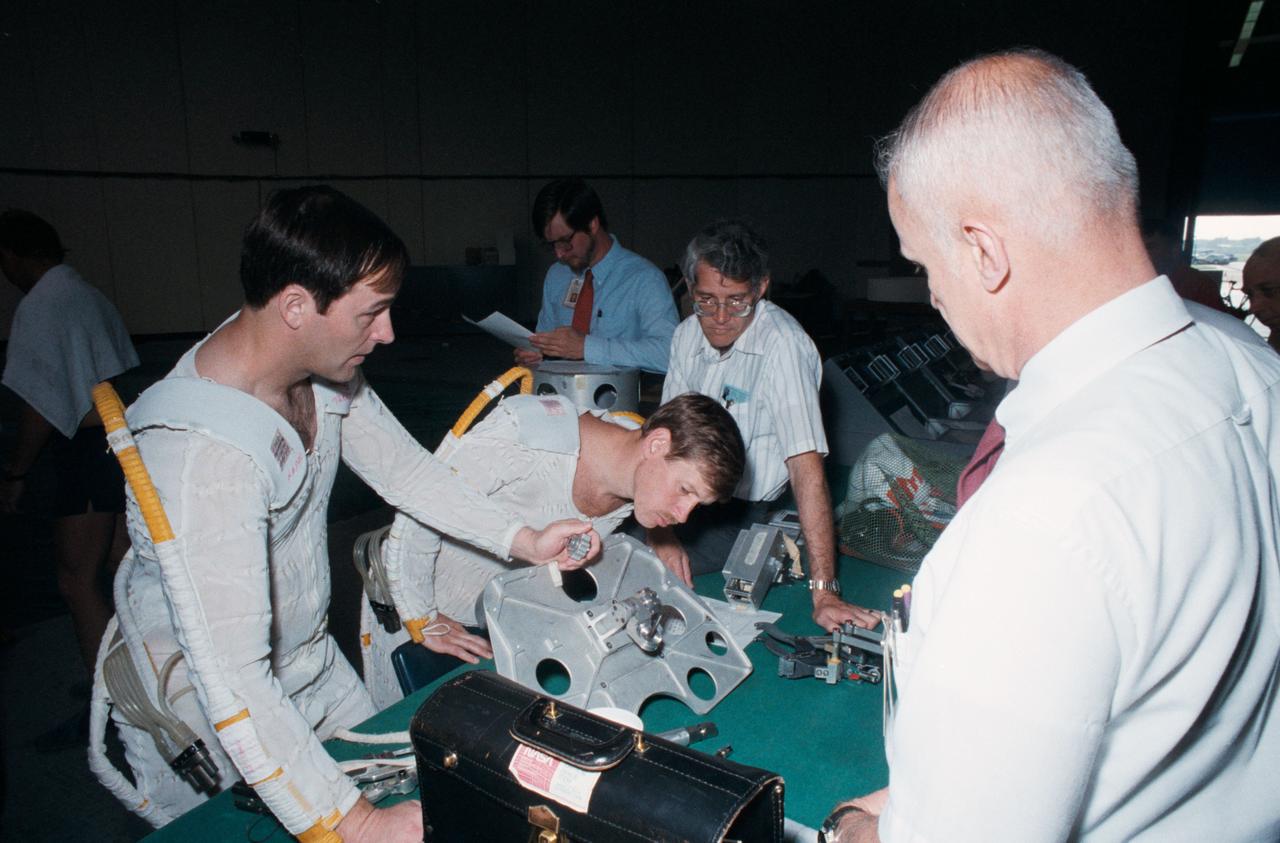
Astronauts Jerry L. Ross (left) and Sherwood Springer (center), look over a foot restraint like that on the currently orbiting Shuttle Discovery. At right is Astronaut Bruce McCandless II. Activities, Bldg. 29, Weightless Environment Training Facility (WETF) for the STS-23/51D Extravehicular Activity (EVA) Simulation for Syncom IV, 04/14/1985. 1. SHUTTLE - SIMULATION (SYNCOM IV) 2. ASTRONAUT ROSS, JERRY L. - SIMULATION (SYNCOM) 3. ASTRONAUT SPRING, SHERWOOD C. - SIMULATION (SYNCOM IV) JSC, HOUSTON, TX
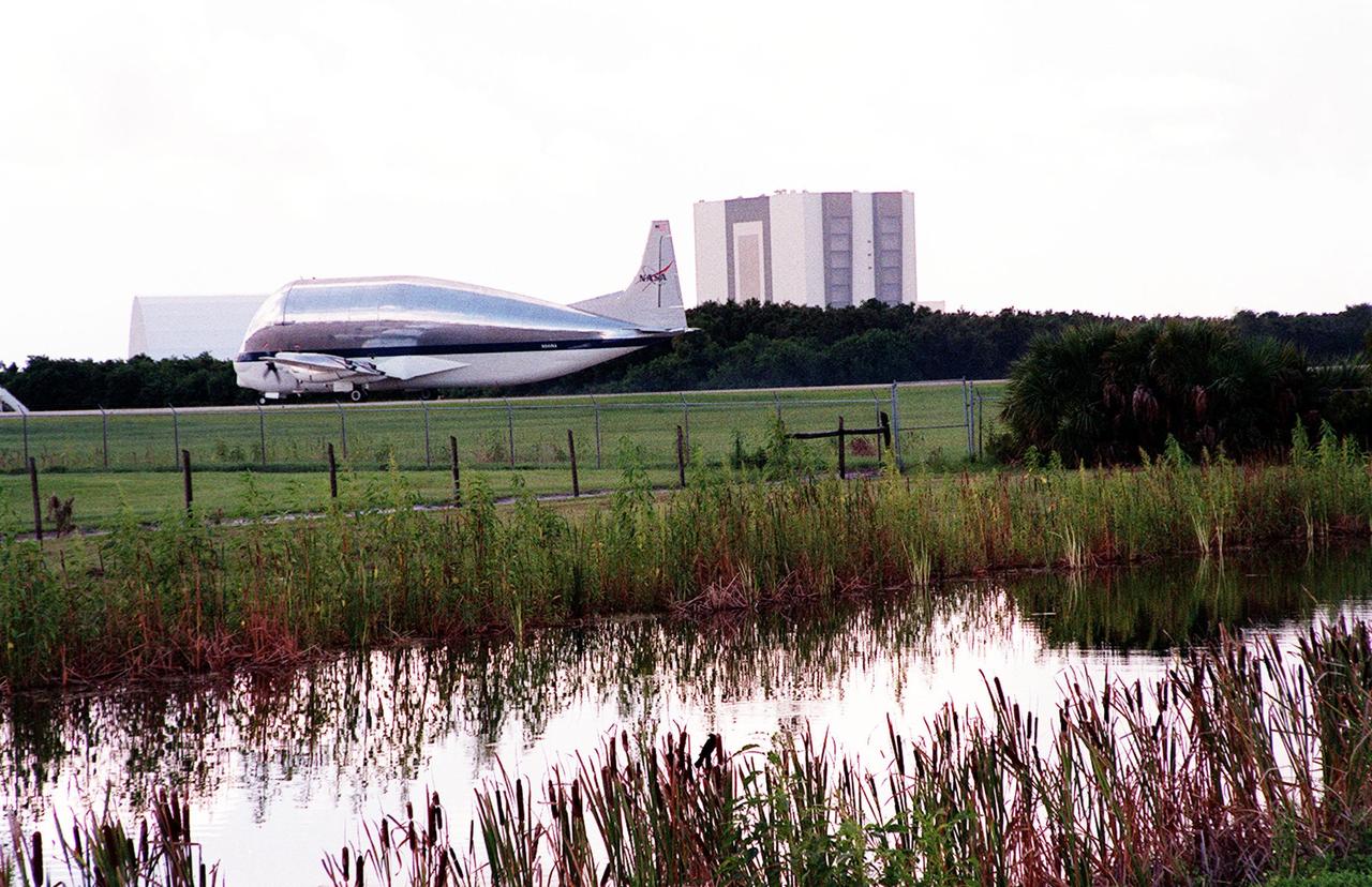
On July 26, 2000 the P-1 truss arrived at Kennedy Space Center’s Shuttle Landing Facility aboard its "Super Guppy" transport. The P-1 truss, scheduled to fly in spring of 2002, is part of a total 10-truss, girder-like structure that will ultimately extend the length of a football field. Astronauts will attach the 14-by-15 foot structure to the port side of the center truss, SO, during the spring assembly flight. The 33,000-pound P-1 will house the thermal radiator rotating joint (TRRJ) that will rotate the International Space Station’s radiators away from the sun to increase their maximum cooling efficiency
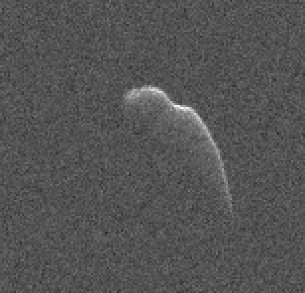
This image of an asteroid that is at least 3,600 feet (1,100 meters) long was taken on Dec. 17, 2015, by scientists using NASA's 230-foot (70-meter) DSS-14 antenna at Goldstone, California. This asteroid, named 2003 SD2020, will safely fly past Earth on Thursday, Dec. 24, at a distance of 6.8 million miles (11 million kilometers). At the time this image was taken, the asteroid was about 7.3 million miles (12 million kilometers) from Earth. In 2018, this asteroid will fly past Earth at a distance of 1.8 million miles (2.8 million kilometers). http://photojournal.jpl.nasa.gov/catalog/PIA20279
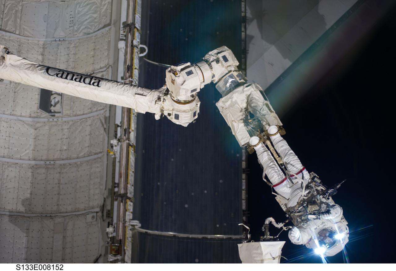
S133-E-008152 (2 March 2011) --- Anchored to a Canadarm2 mobile foot restraint, NASA astronaut Steve Bowen, STS-133 mission specialist, participates in the mission’s second session of extravehicular activity (EVA) as construction and maintenance continue on the International Space Station. During the six-hour, 14-minute spacewalk, Bowen and astronaut Alvin Drew (out of frame), mission specialist, tackled a variety of tasks, including venting into space some remaining ammonia from a failed pump module they moved during the mission’s first spacewalk. Photo credit: NASA or National Aeronautics and Space Administration
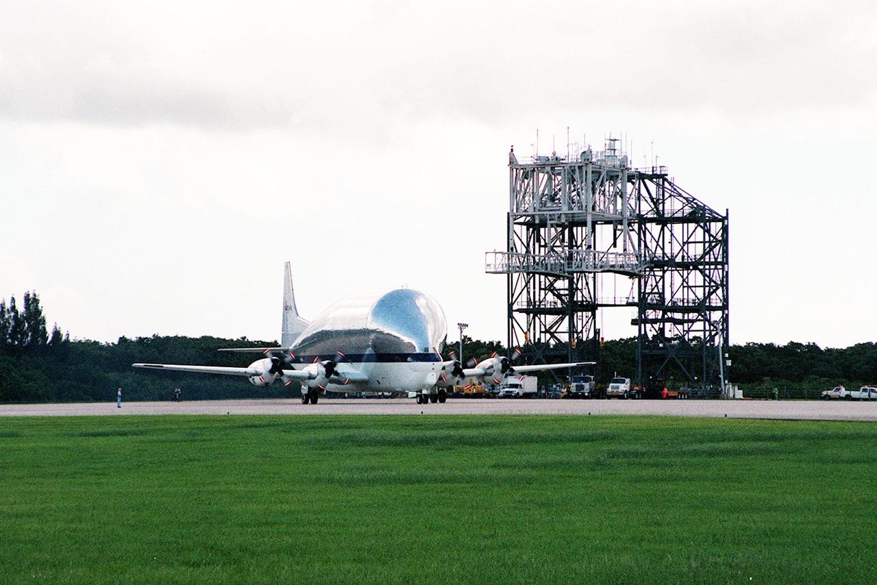
On July 26, 2000 the P-1 truss arrived at Kennedy Space Center’s Shuttle Landing Facility aboard its "Super Guppy" transport. The P-1 truss, scheduled to fly in spring of 2002, is part of a total 10-truss, girder-like structure that will ultimately extend the length of a football field. Astronauts will attach the 14-by-15 foot structure to the port side of the center truss, SO, during the spring assembly flight. The 33,000-pound P-1 will house the thermal radiator rotating joint (TRRJ) that will rotate the International Space Station’s radiators away from the sun to increase their maximum cooling efficiency
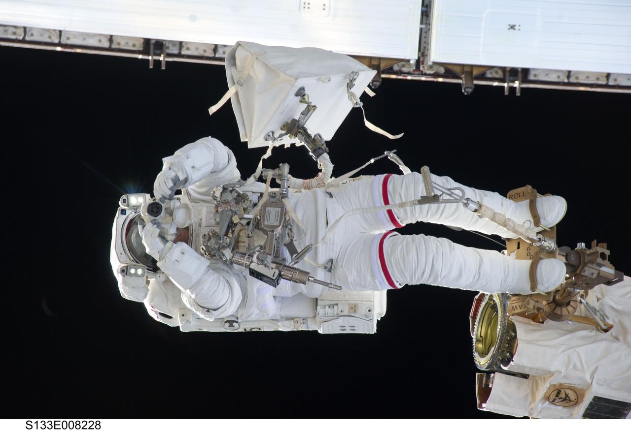
S133-E-008228 (2 March 2011) --- Anchored to a Canadarm2 mobile foot restraint, NASA astronaut Steve Bowen, STS-133 mission specialist, participates in the mission’s second session of extravehicular activity (EVA) as construction and maintenance continue on the International Space Station. During the six-hour, 14-minute spacewalk, Bowen and astronaut Alvin Drew (out of frame), mission specialist, tackled a variety of tasks, including venting into space some remaining ammonia from a failed pump module they moved during the mission’s first spacewalk. Photo credit: NASA or National Aeronautics and Space Administration
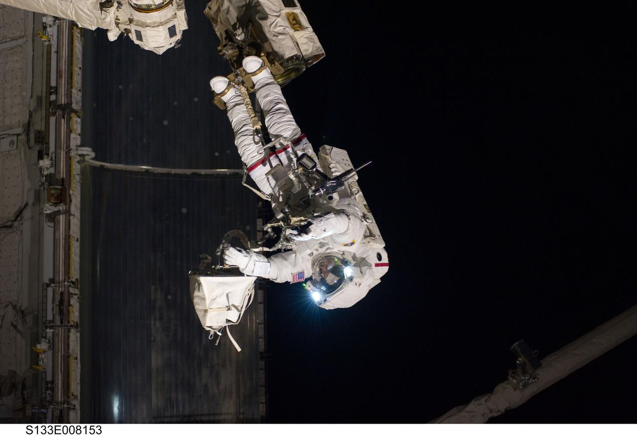
S133-E-008153 (2 March 2011) --- Anchored to a Canadarm2 mobile foot restraint, NASA astronaut Steve Bowen, STS-133 mission specialist, participates in the mission’s second session of extravehicular activity (EVA) as construction and maintenance continue on the International Space Station. During the six-hour, 14-minute spacewalk, Bowen and astronaut Alvin Drew (out of frame), mission specialist, tackled a variety of tasks, including venting into space some remaining ammonia from a failed pump module they moved during the mission’s first spacewalk. Photo credit: NASA or National Aeronautics and Space Administration
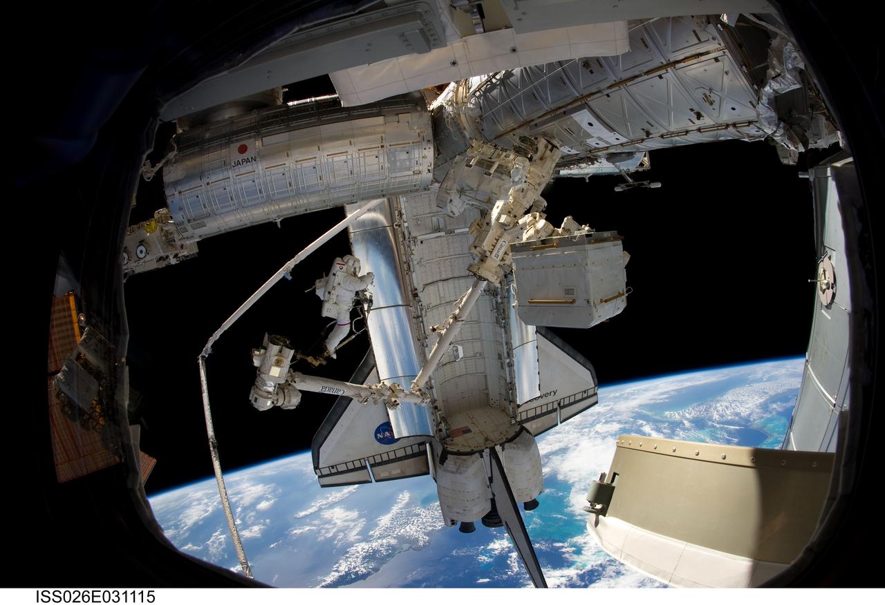
ISS026-E-031115 (2 March 2011) --- Anchored to a Canadarm2 mobile foot restraint, NASA astronaut Steve Bowen, STS-133 mission specialist, participates in the mission?s second session of extravehicular activity (EVA) as construction and maintenance continue on the International Space Station. During the six-hour, 14-minute spacewalk, Bowen and astronaut Alvin Drew (out of frame), mission specialist, tackled a variety of tasks, including venting into space some remaining ammonia from a failed pump module they moved during the mission?s first spacewalk. Photo credit: NASA or National Aeronautics and Space Administration
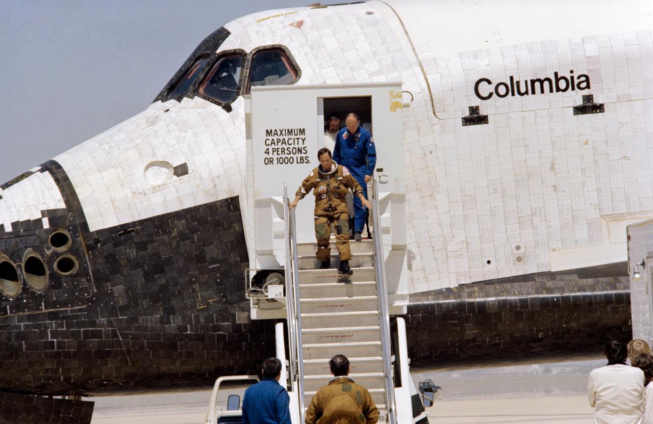
S81-30852 (14 April 1981) --- Astronaut Robert L. Crippen, pilot for the STS-1 flight, egresses the NASA space shuttle following touchdown of the Columbia on Rogers Dry Lake at Edwards Air Force Base, California. Astronaut John W. Young, crew commander, had earlier exited the craft and can be seen standing at the foot of the steps with George W.S. Abbey, director of flight operations at the Johnson Space Center (JSC). Dr. Craig L. Fischer, chief of the medical operations branch in JSC?s medical sciences division, follows Crippen down the steps. Photo credit: NASA
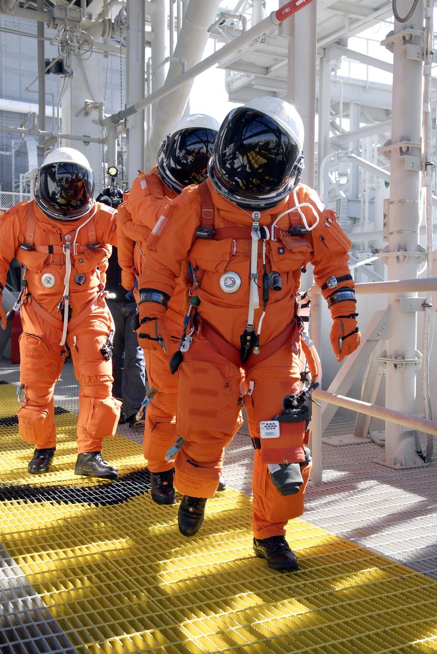
CAPE CANAVERAL, Fla. – Following the simulated launch countdown on Launch Pad 39A at NASA's Kennedy Space Center in Florida, STS-119 crew members practice an emergency egress from the 195-foot level of the fixed service structure as part of the prelaunch preparation known as Terminal Countdown Demonstration Test. The TCDT also includes equipment familiarization. Discovery is targeted to launch on the STS-119 mission Feb. 12. During the 14-day mission, the crew will install the S6 truss segment and solar arrays to the starboard side of the International Space Station, completing the station's truss, or backbone. Photo credit: NASA/Kim Shiflett
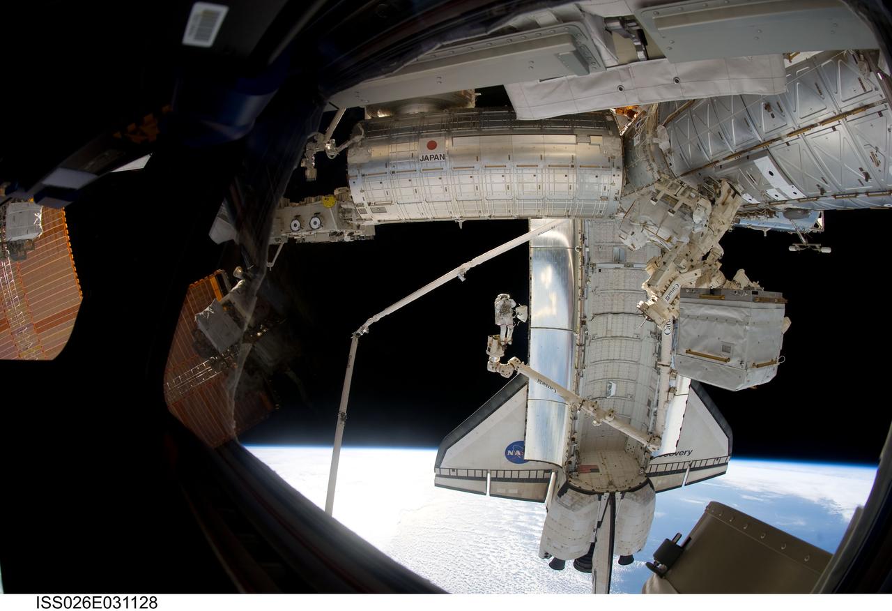
ISS026-E-031128 (2 March 2011) --- Anchored to a Canadarm2 mobile foot restraint, NASA astronaut Steve Bowen, STS-133 mission specialist, participates in the mission?s second session of extravehicular activity (EVA) as construction and maintenance continue on the International Space Station. During the six-hour, 14-minute spacewalk, Bowen and astronaut Alvin Drew (out of frame), mission specialist, tackled a variety of tasks, including venting into space some remaining ammonia from a failed pump module they moved during the mission?s first spacewalk. Photo credit: NASA or National Aeronautics and Space Administration

On July 26, 2000 the P-1 truss arrived at Kennedy Space Center’s Shuttle Landing Facility aboard its "Super Guppy" transport. The P-1 truss, scheduled to fly in spring of 2002, is part of a total 10-truss, girder-like structure that will ultimately extend the length of a football field. Astronauts will attach the 14-by-15 foot structure to the port side of the center truss, SO, during the spring assembly flight. The 33,000-pound P-1 will house the thermal radiator rotating joint (TRRJ) that will rotate the International Space Station’s radiators away from the sun to increase their maximum cooling efficiency

The P-1 truss, a component of the International Space Station, is lowered into a work stand in the Operations and Checkout Building where it will undergo processing. Scheduled to fly in spring of 2002, the P-1 is part of a total 10-truss, girder-like structure on the Station that will ultimately extend the length of a football field. Astronauts will attach the 14-by-15 foot structure to the port side of the center truss, S0, during the spring assembly flight. The 33,000-pound P-1 will house the thermal radiator rotating joint (TRRJ) that will rotate the Station’s radiators away from the sun to increase their maximum cooling efficiency
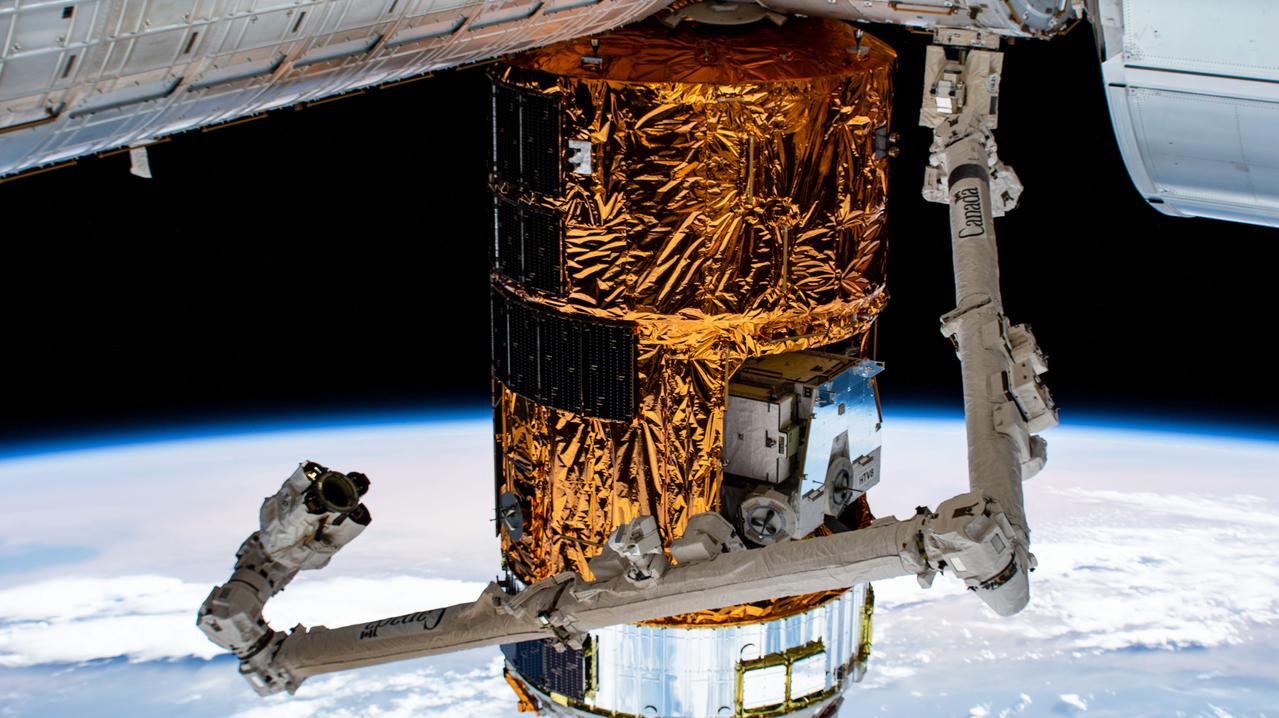
iss063e070805 (Aug. 14, 2020) --- Canada’s versatile robotic arm, the 57.7-foot-long Canadarm2, is poised to grapple and remove JAXA’s (Japan Aerospace Exploration Agency) resupply ship, the H-II Transfer Vehicle-9 (HTV-9), from the Harmony module. Commander Chris Cassidy of NASA will command the Canadarm2 to release the HTV-9 on Tuesday, Aug. 18, at 1:35 p.m. EDT. The HTV-9 arrived at the station on May 25, 2020, delivering four tons of new science experiments, station hardware, crew supplies and fuel.

51A-104-049 (14 Nov. 1984) --- Astronaut Dale A. Gardner, having just completed the major portion of his second extravehicular activity (EVA) period in three days aboard the Earth-orbiting Discovery, holds up a for sale sign. Astronaut Joseph P. Allen IV, who also participated in the two EVA, is reflected in Gardner's helmet visor. A portion of each of two recovered satellites is in lower right corner, with Westar nearer Discovery's aft. Dr. Allen, standing on the mobile foot restraint, connected to the remote manipulator system. Photo credit: NASA
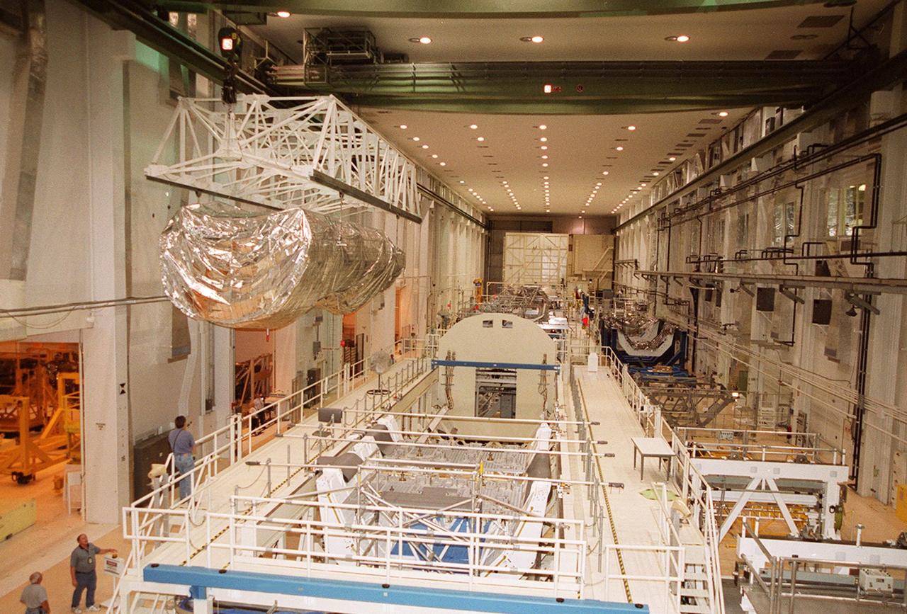
The P-1 truss, a component of the International Space Station, is moved the length of the Operations and Checkout Building to its work stand where it will undergo processing. Scheduled to fly in spring of 2002, the P-1 is part of a total 10-truss, girder-like structure on the Station that will ultimately extend the length of a football field. Astronauts will attach the 14-by-15 foot structure to the port side of the center truss, S0, during the spring assembly flight. The 33,000-pound P-1 will house the thermal radiator rotating joint (TRRJ) that will rotate the Station’s radiators away from the sun to increase their maximum cooling efficiency

Technicians from NASA’s Exploration Ground Systems use massive cranes inside the agency’s Vehicle Assembly Building (VAB) to lift the fully assembled SLS (Space Launch System) core stage vertically 225 feet above the ground from High Bay 2 to a horizontal position in the facility’s transfer aisle at NASA’s Kennedy Space Center in Florida on Friday, March 14, 2025. The 212-foot core stage will undergo final checkouts before being lifted into the VAB’s High Bay 3 for integration alongside the completed stack of twin solid rocket booster segments.
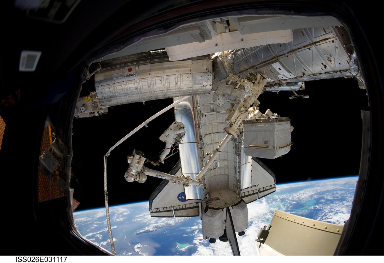
ISS026-E-031117 (2 March 2011) --- Anchored to a Canadarm2 mobile foot restraint, NASA astronaut Steve Bowen, STS-133 mission specialist, participates in the mission?s second session of extravehicular activity (EVA) as construction and maintenance continue on the International Space Station. During the six-hour, 14-minute spacewalk, Bowen and astronaut Alvin Drew (out of frame), mission specialist, tackled a variety of tasks, including venting into space some remaining ammonia from a failed pump module they moved during the mission?s first spacewalk. Photo credit: NASA or National Aeronautics and Space Administration

STS066-117-014 (3-14 Nov. 1994) --- Malaspina Glacier can be seen in this north-northeastern photograph taken in November, 1994. The glacier, located in the south shore of Alaska is a classic example of a piedmont glacier lying along the foot of a mountain range. The principal source of ice for the glacier is provided by the Seward Ice Field to the north (top portion of the view) which flows through three narrow outlets onto the coastal plain. The glacier moves in surges that rush earlier-formed moraines outward into the expanding concentric patterns along the flanks of the ice mass.
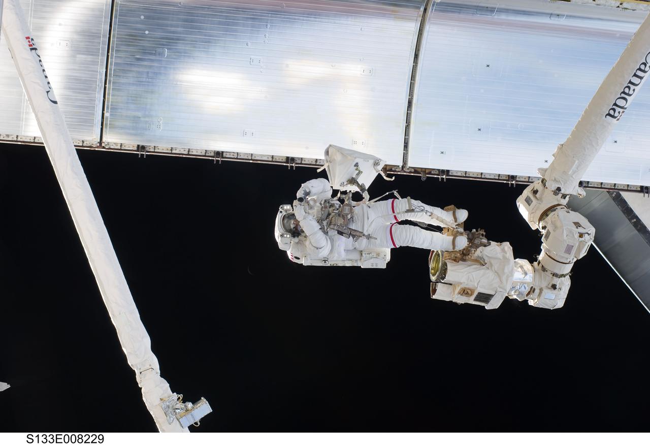
S133-E-008229 (2 March 2011) --- Anchored to a Canadarm2 mobile foot restraint, NASA astronaut Steve Bowen, STS-133 mission specialist, participates in the mission’s second session of extravehicular activity (EVA) as construction and maintenance continue on the International Space Station. During the six-hour, 14-minute spacewalk, Bowen and astronaut Alvin Drew (out of frame), mission specialist, tackled a variety of tasks, including venting into space some remaining ammonia from a failed pump module they moved during the mission’s first spacewalk. Photo credit: NASA or National Aeronautics and Space Administration
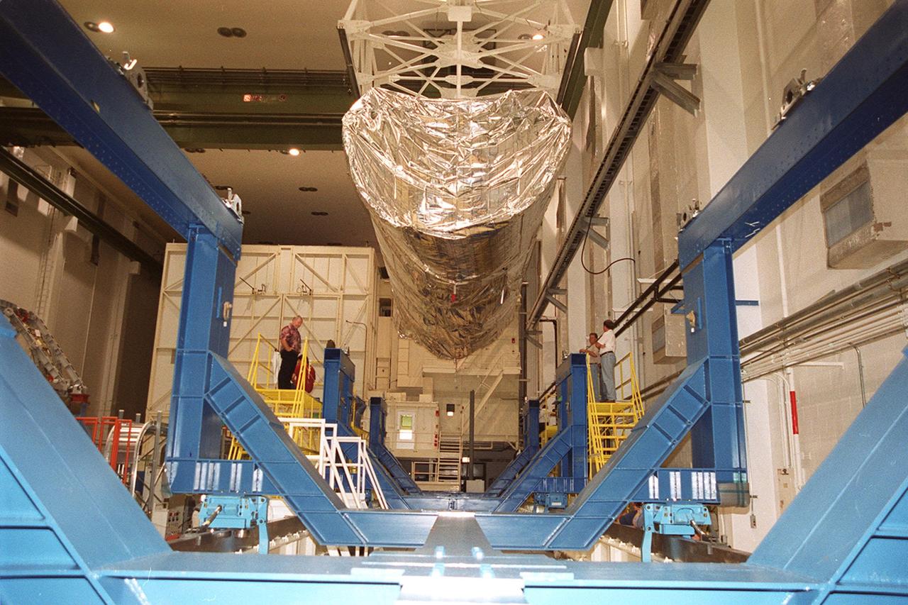
Inside the Operations and Checkout Building, an overhead crane lifts the top of the canister containing the P-1 truss, a component of the International Space Station. The truss, scheduled to fly in spring of 2002, is part of a total 10-truss, girder-like structure on the Station that will ultimately extend the length of a football field. Astronauts will attach the 14-by-15 foot structure to the port side of the center truss, S0, during the spring assembly flight. The 33,000-pound P-1 will house the thermal radiator rotating joint (TRRJ) that will rotate the Station’s radiators away from the sun to increase their maximum cooling efficiency
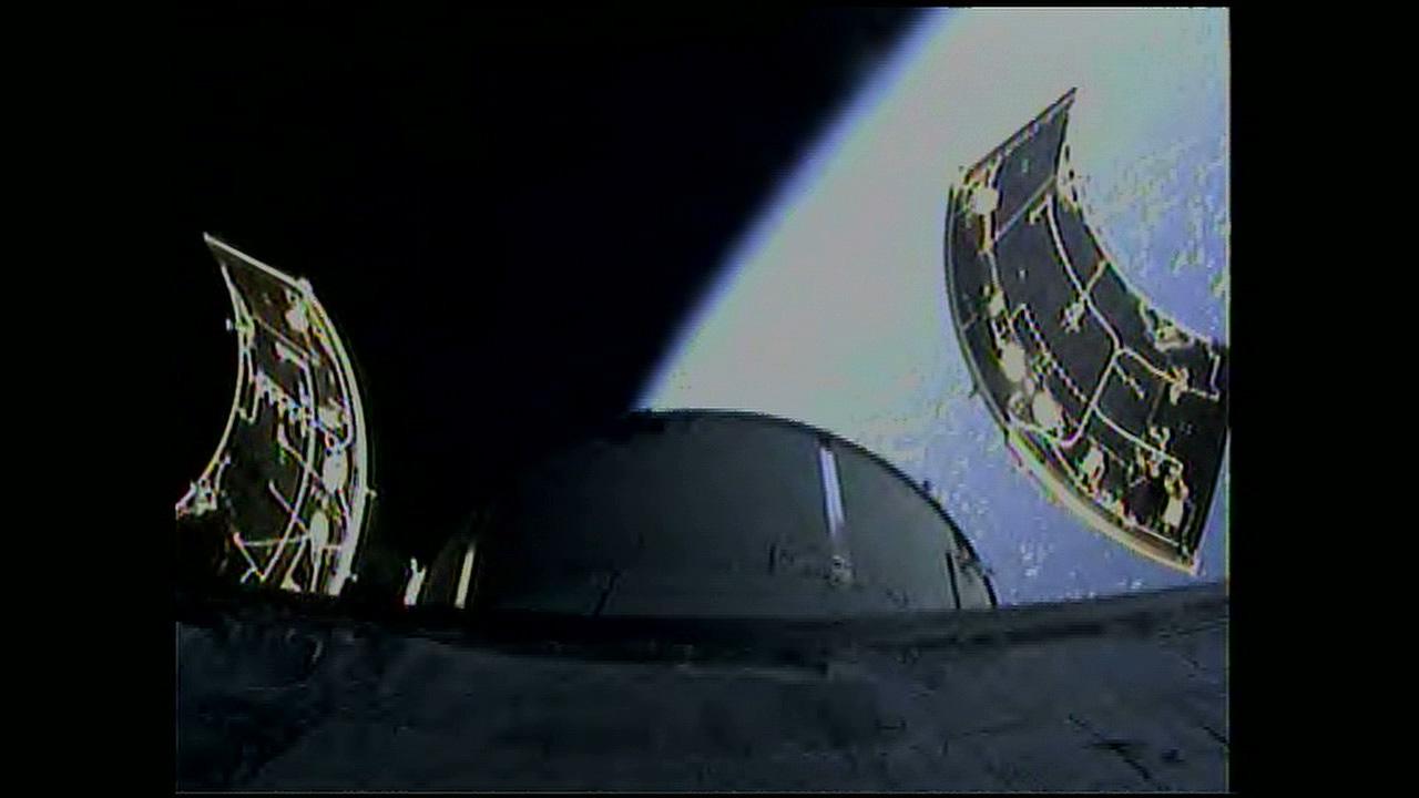
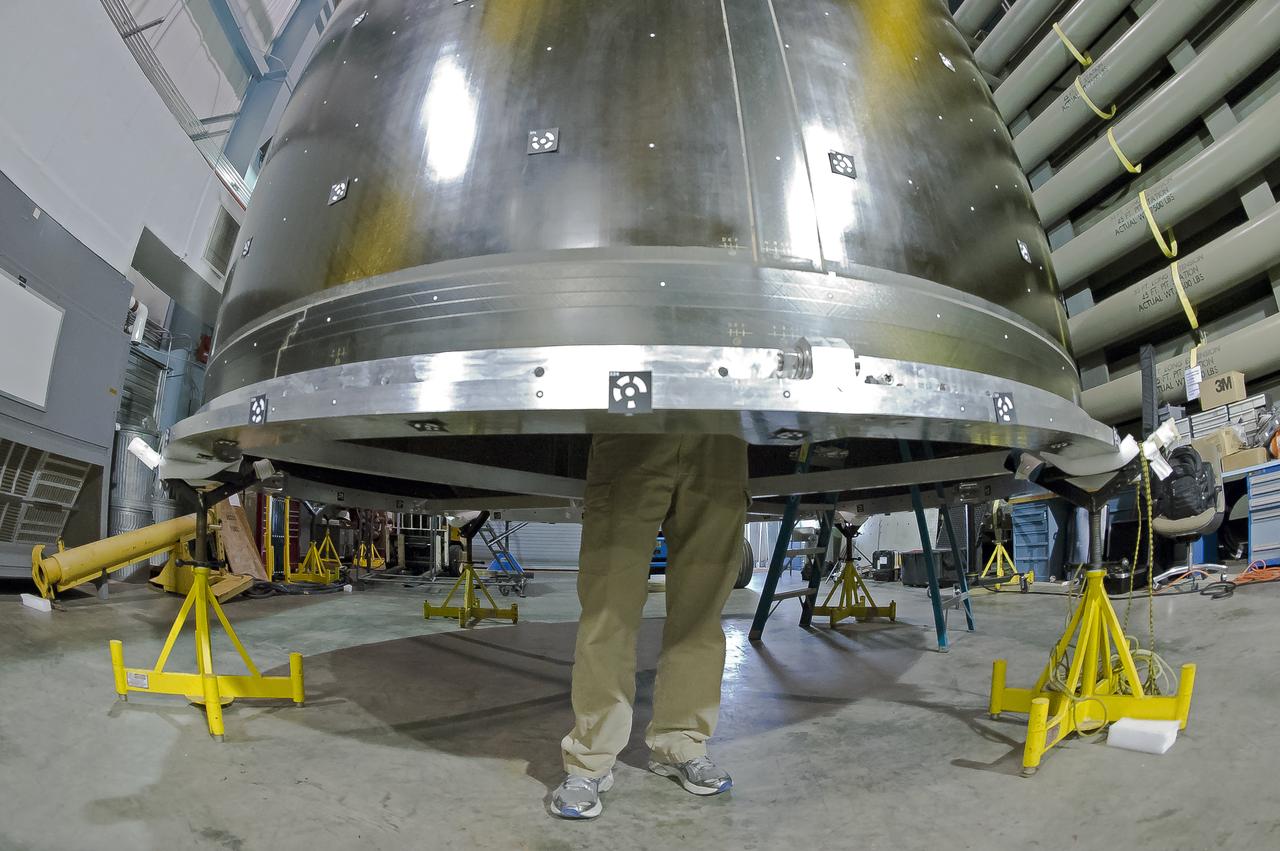
An onboard camera captures separation of the three 13 by 14-foot Orion service module fairings following lift off the Delta IV Heavy rocket from Space Launch Complex 37 at Cape Canaveral Air Force Station in Florida on Dec. 5, 2014. Exploration Flight Test-1 (EFT-1) also will validate systems such as Orion’s parachutes, avionics and attitude control, and demonstrate major separation events such as the launch abort system jettison and the service module fairing separation. Part of Batch image transfer from Flickr.
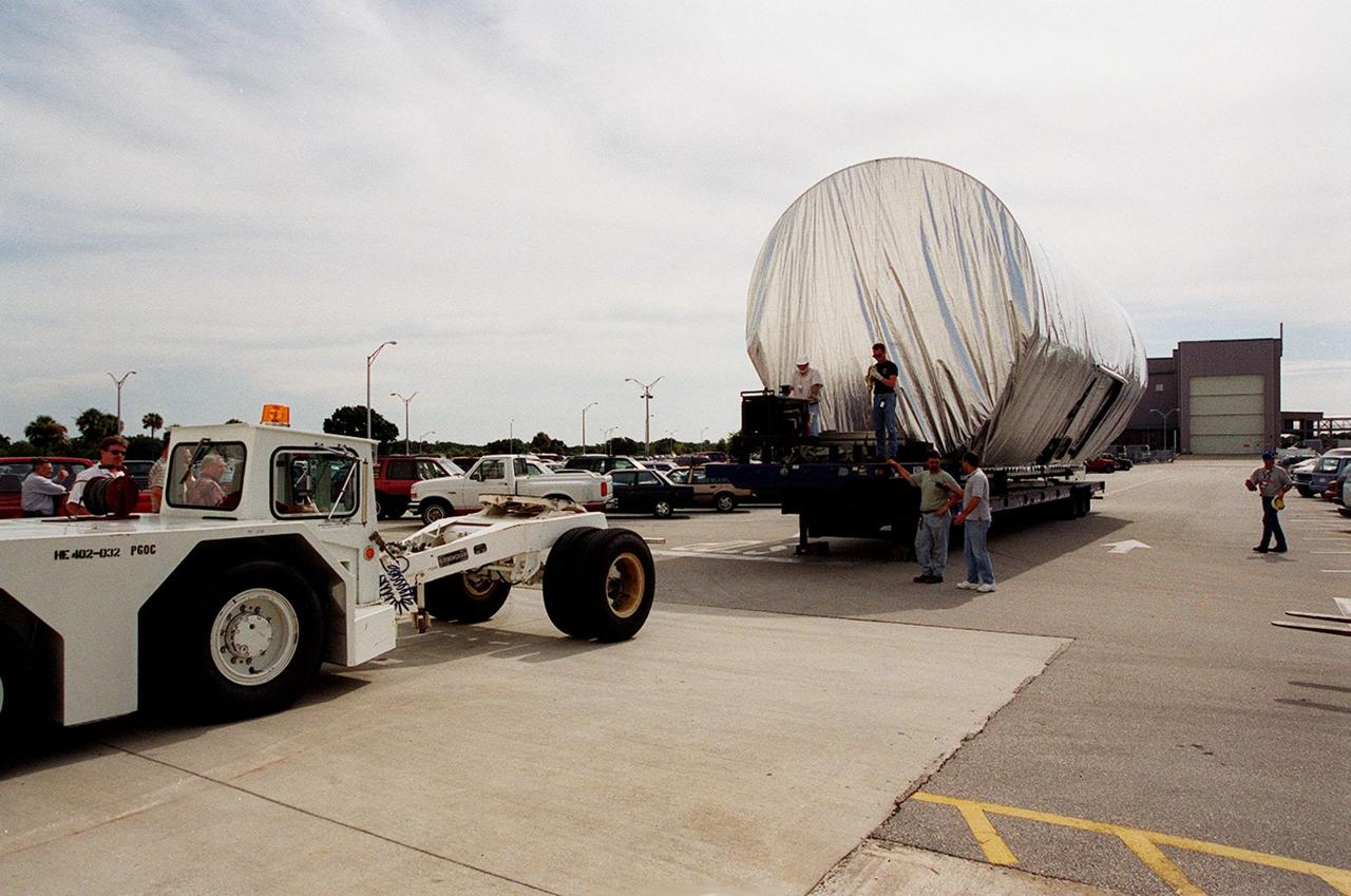
The P-1 truss, a component of the International Space Station, arrives in the parking lot outside the Operations and Checkout Building where it will undergo processing. The P-1 truss, scheduled to fly in spring of 2002, is part of a total 10-truss, girder-like structure on the Space Station that will ultimately extend the length of a football field. Astronauts will attach the 14-by-15 foot structure to the port side of the center truss, S0, during the spring assembly flight. The 33,000-pound P-1 will house the thermal radiator rotating joint (TRRJ) that will rotate the Station’s radiators away from the sun to increase their maximum cooling efficiency
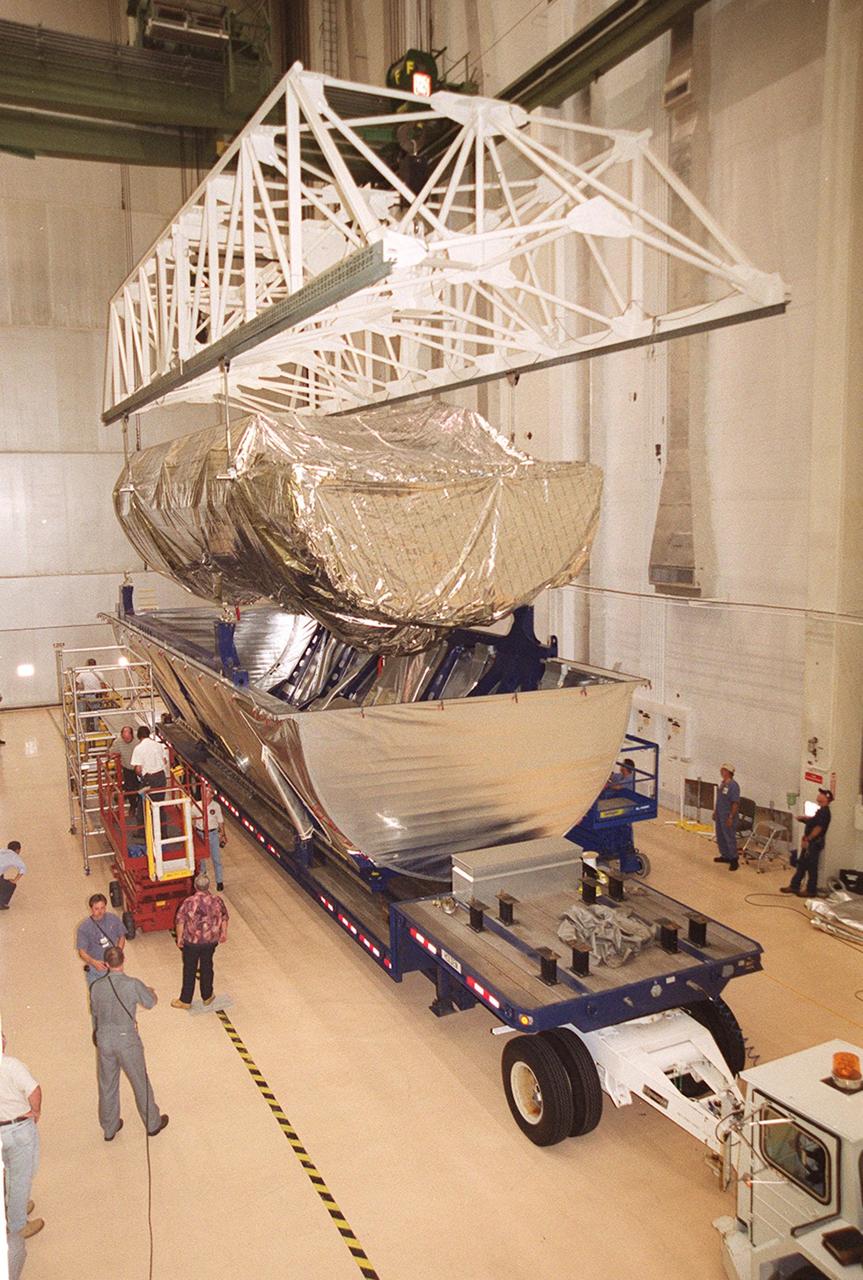
Inside the Operations and Checkout Building, the P-1 truss, a component of the International Space Station, is lifted out of its canister to move to a work stand where it will undergo processing. Scheduled to fly in spring of 2002, the P-1 is part of a total 10-truss, girder-like structure on the Station that will ultimately extend the length of a football field. Astronauts will attach the 14-by-15 foot structure to the port side of the center truss, S0, during the spring assembly flight. The 33,000-pound P-1 will house the thermal radiator rotating joint (TRRJ) that will rotate the Station’s radiators away from the sun to increase their maximum cooling efficiency
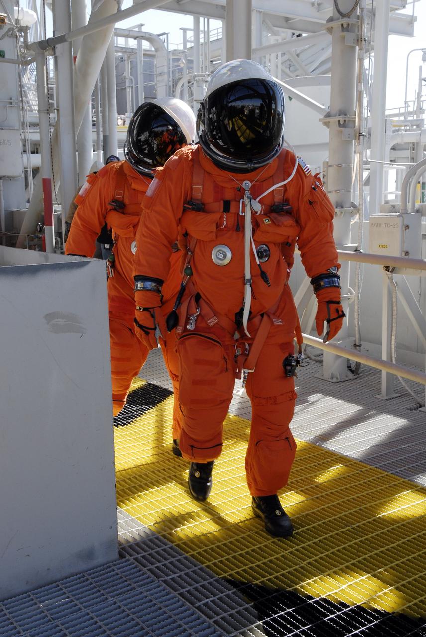
CAPE CANAVERAL, Fla. – Following the simulated launch countdown on Launch Pad 39A at NASA's Kennedy Space Center in Florida, STS-119 crew members practice an emergency egress from the 195-foot level of the fixed service structure as part of the prelaunch preparation known as Terminal Countdown Demonstration Test. The TCDT also includes equipment familiarization. Discovery is targeted to launch on the STS-119 mission Feb. 12. During the 14-day mission, the crew will install the S6 truss segment and solar arrays to the starboard side of the International Space Station, completing the station's truss, or backbone. Photo credit: NASA/Kim Shiflett
STS063-21-011 (9 Feb 1995) --- Astronaut Bernard A. Harris, Jr., payload commander, standing on a foot restraint attached to the Remote Manipulator System (RMS) arm carries astronaut C. Michael Foale, mission specialist, during their shared Extravehicular Activity (EVA) in the Space Shuttle Discovery's cargo bay. This is one of 16 still photographs released by the NASA Johnson Space Center (JSC) Public Affairs Office (PAO) on February 14, 1995. Others onboard the Discovery were astronauts James D. Wetherbee, mission commander; Eileen M. Collins, pilot; mission specialists Janice E. Voss and cosmonaut Vladimir G. Titov.
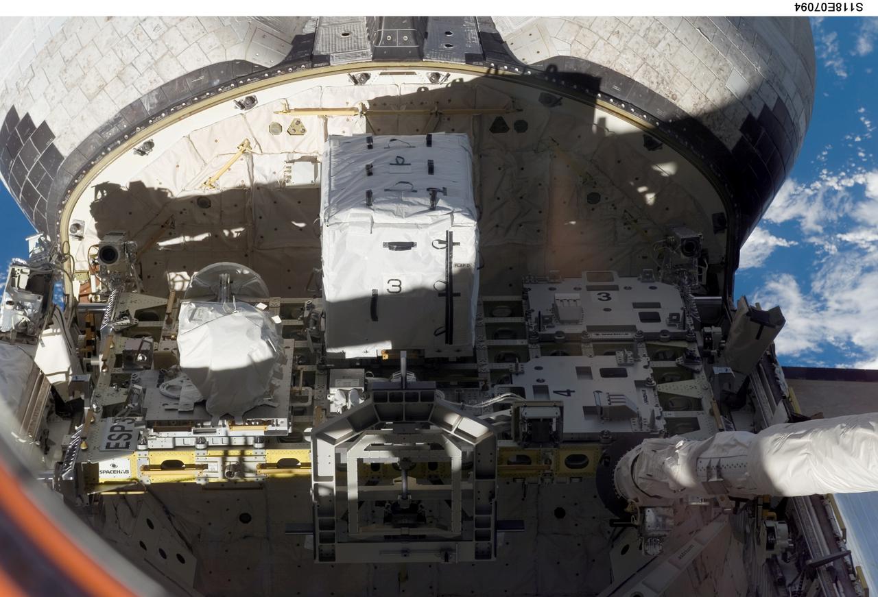
S118-E-07094 (14 Aug. 2007) --- An external stowage platform (ESP-3) is photographed in the payload bay of Space Shuttle Endeavour while docked with the International Space Station. Astronauts Tracy Caldwell and Barbara R. Morgan, both STS-118 mission specialists, were inside at Endeavour's controls as the shuttle's robotic arm (lower right) lifted the storage platform from the cargo bay to hand it over to the station's robotic arm, also known as Canadarm2. Astronauts Charlie Hobaugh, pilot, and Clay Anderson, Expedition 15 flight engineer, then used Canadarm2 to attach the 13-by-7-foot platform to the station's Port 3 truss.
Workers oversee the placement of the P-1 truss, a component of the International Space Station, onto the bed of a transport vehicle that will move it to the Operations and Checkout Building for processing. The P-1 truss, scheduled to fly in spring of 2002, is part of a total 10-truss, girder-like structure on the Station that will ultimately extend the length of a football field. Astronauts will attach the 14-by-15 foot structure to the port side of the center truss, S0, during the spring assembly flight. The 33,000-pound P-1 will house the thermal radiator rotating joint (TRRJ) that will rotate the Station’s radiators away from the sun to increase their maximum cooling efficiency
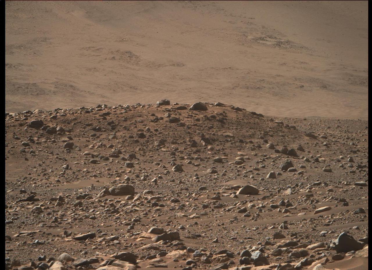
This image of NASA's Ingenuity Mars Helicopter at "Airfield Mu" was taken by the Mastcam-Z instrument aboard Perseverance on April 14, 2023, the 764th Martian day, or sol, of the rover's mission. The helicopter's landing hazard avoidance algorithm helped guide it to a safe landing at Mu the previous sol, after completing its 50th flight. The helicopter is just below and to the left of center in the image. It is about 720 feet (220 meters) away from the rover. The approximately 4-foot-wide (1.2-meter-wide) split boulder, which appears to be directly in front and to the right of the helicopter, is actually about 380 feet (115 meters) in front of the rotorcraft. https://photojournal.jpl.nasa.gov/catalog/PIA25883
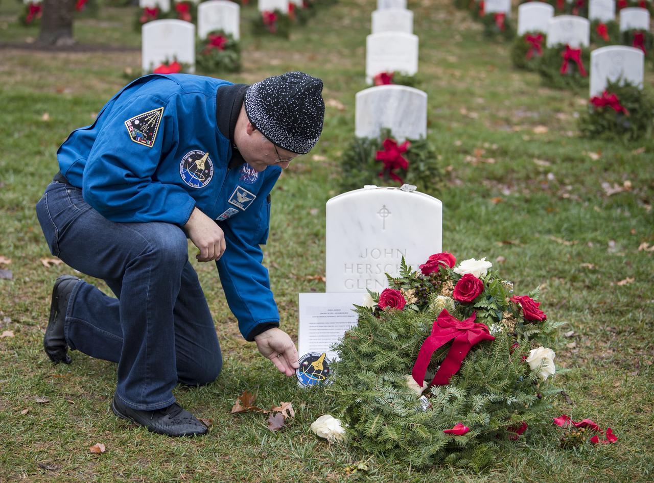
NASA astronaut Doug Wheelock leaves his STS-120 mission patch at the gravesite of former astronaut and U.S. Senator John Glenn during National Wreaths Across America Day at Arlington National Cemetery, Sat., Dec. 14, 2019 in Arlington, Va. National Wreaths Across America Day is held annually to celebrate the lives of military veterans and wreaths are placed at the foot of every headstone. Wheelock honored those who lost their lives in the quest for space exploration as well as fellow service members. Photo Credit: (NASA/Aubrey Gemignani)
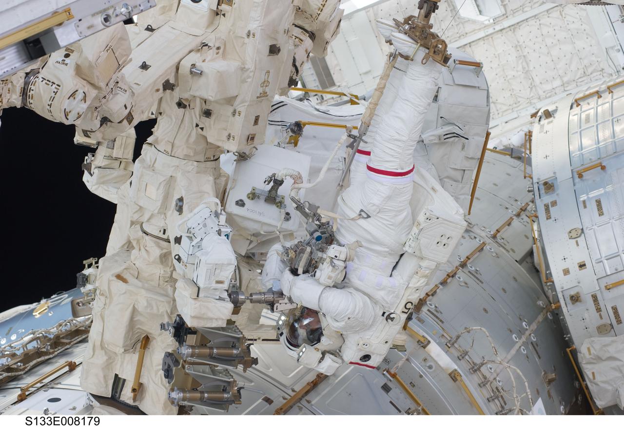
S133-E-008179 (2 March 2011) --- Anchored to a Canadarm2 mobile foot restraint, NASA astronaut Steve Bowen, STS-133 mission specialist, participates in the mission’s second session of extravehicular activity (EVA) as construction and maintenance continue on the International Space Station. During the six-hour, 14-minute spacewalk, Bowen and astronaut Alvin Drew (out of frame), mission specialist, tackled a variety of tasks, including venting into space some remaining ammonia from a failed pump module they moved during the mission’s first spacewalk. Photo credit: NASA or National Aeronautics and Space Administration