Instrumentation in 16 Foot Wind Tunnel manometer boards
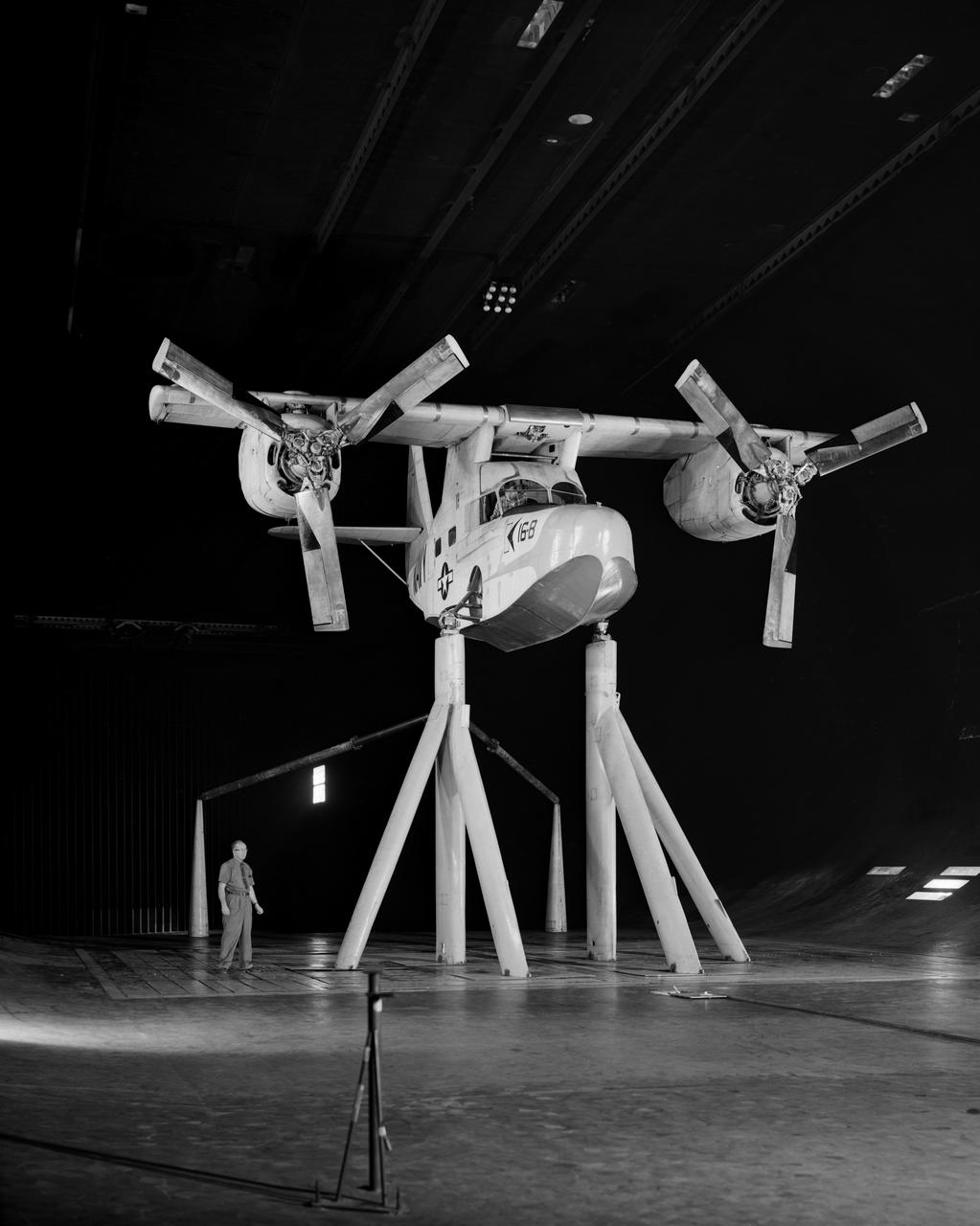
Test No. 175 Kaman K-16 in 40x80 Foot Wind Tunnel at Ames Research Center. Pictured with two Kaman employees. 3/4 Front view of Airplane. Kaman K-16B was an experimental tilt wing aircraft, it used the fuselage of a JRF-5 and was powered by two General Electric YT58-GE-2A engines.

16 Foot Wind Tunnel personnel at work
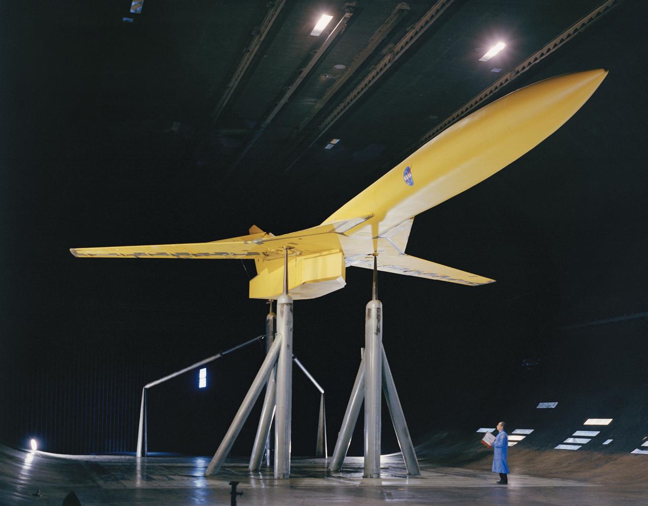
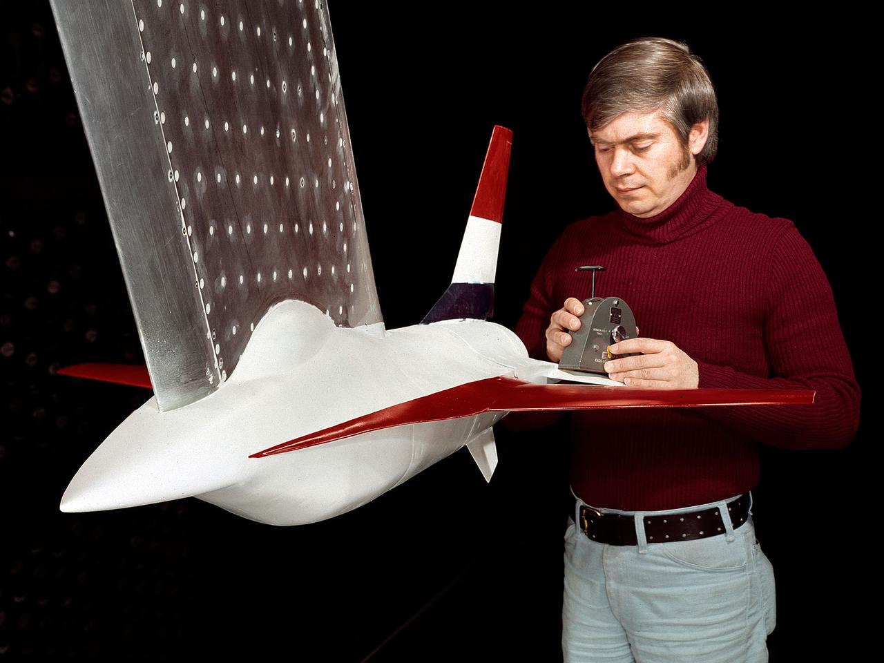
3/4 view of model in cruise configuration with 25 deg. Sweep, AR=6.9. SCAT-16; Variable Sweep Model in 40x80 Wind Tunnel at NASA Ames.
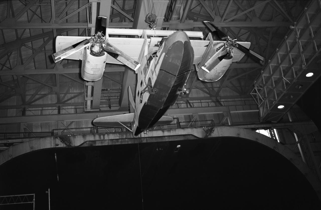
Test No. 175 Kaman K-16 being lowered into the 40x80 foot wind tunnel at NASA's Ames Research Center, viewed from the front. Kaman K-16B was an experimental tilt wing aircraft, it used the fuselage of a JRF-5 and was powered by two General Electric YT58-GE-2A engines.
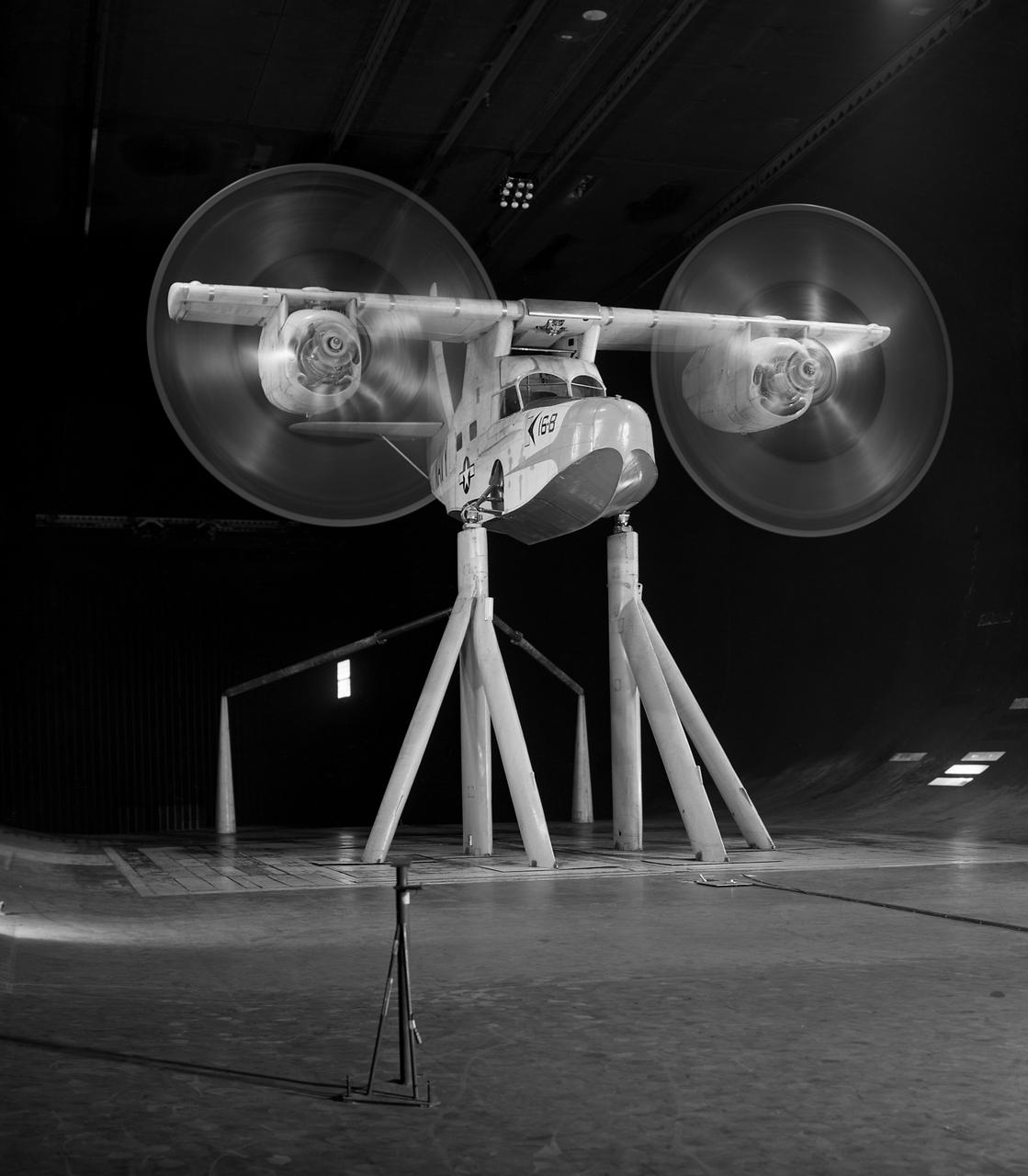
Test No. 175 Kaman K-16 in 40x80 Foot Wind Tunnel at Ames Research Center. Kaman K-16B was an experimental tilt wing aircraft, it used the fuselage of a JRF-5 and was powered by two General Electric YT58-GE-2A engines.
A model of the General Dynamics YF-16 Fighting Falcon in the test section of the 8- by 6-Foot Supersonic Wind Tunnel at the National Aeronautics and Space Administration (NASA) Lewis Research Center. The YF-16 was General Dynamics response to the military’s 1972 request for proposals to design a new 20,000-pound fighter jet with exceptional acceleration, turn rate, and range. The aircraft included innovative design elements to help pilots survive turns up to 9Gs, a new frameless bubble canopy, and a Pratt and Whitney 24,000-pound thrust F-100 engine. The YF-16 made its initial flight in February 1974, just six weeks before this photograph, at Edwards Air Force Base. Less than a year later, the Air Force ordered 650 of the aircraft, designated as F-16 Fighting Falcons. The March and April 1974 tests in the 8- by 6-foot tunnel analyzed the aircraft’s fixed-shroud ejector nozzle. The fixed-nozzle area limited drag, but also limited the nozzle’s internal performance. NASA researchers identified and assessed aerodynamic and aerodynamic-propulsion interaction uncertainties associated the prototype concept. YF-16 models were also tested extensively in the 11- by 11-Foot Transonic Wind Tunnel and 9- by 7-Foot Supersonic Wind Tunnel at Ames Research Center and the 12-Foot Pressure Wind Tunnel at Langley Research Center.
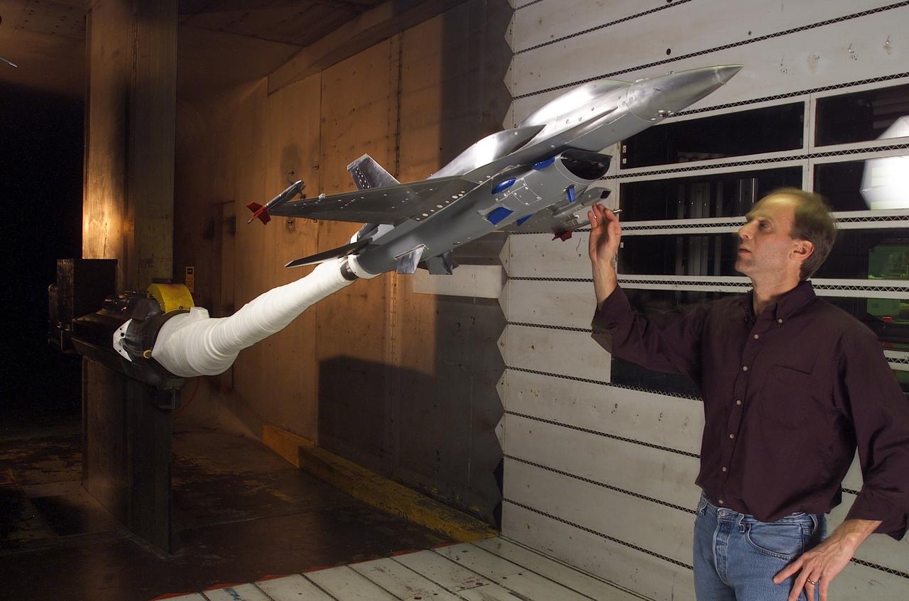
F-16 POD test with IR Sensor; 11ft w.t. test-11-0113) with Doug Atler
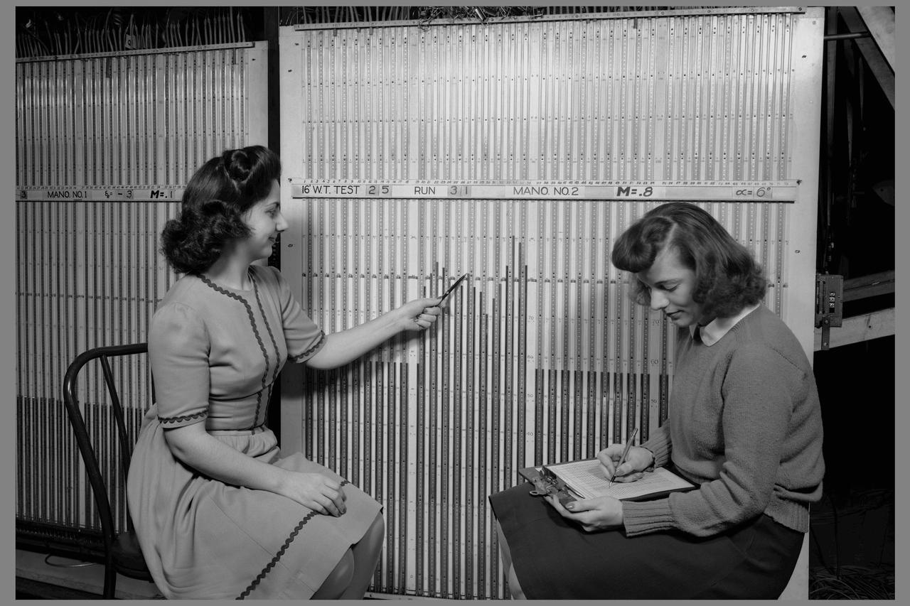
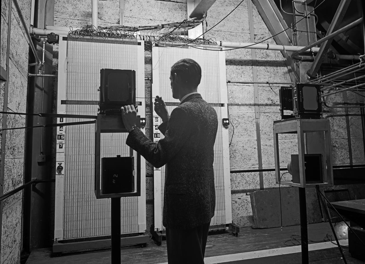
Computers' at work in 16ft wind tunnel - calculating test data - reading manometer board
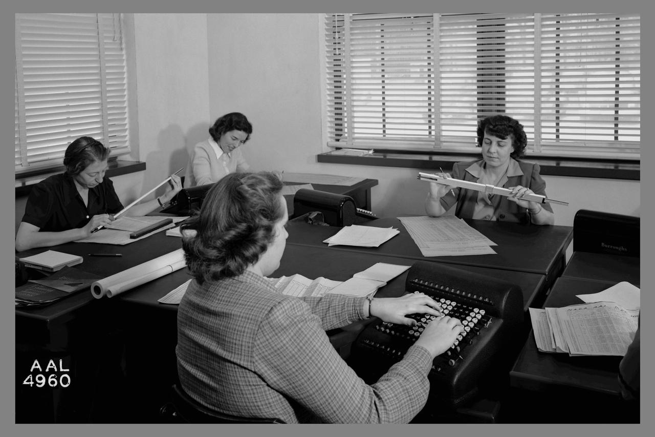
Computers' at work in 16ft wind tunnel - calculating test data
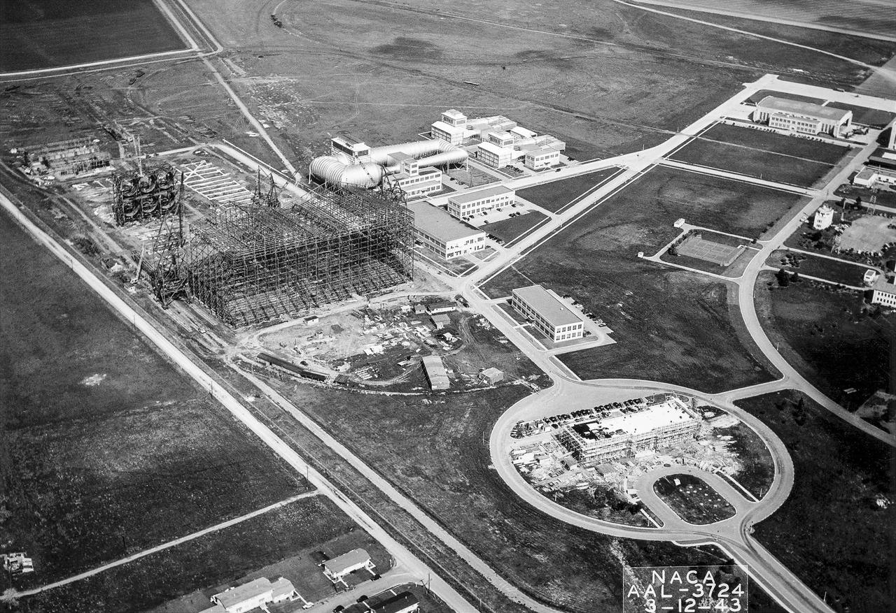
(03/12/1943) Aerial view of the site from the 40x80 wind tunnel At NASA Ames Research Center. Site includes the 16 foot and 7x10 wind tunnels in the background. Building 200 also under construction. Framing for the drive fans of the 40x80 in scene.

Computers' at work in 16ft wind tunnel - calculating test data
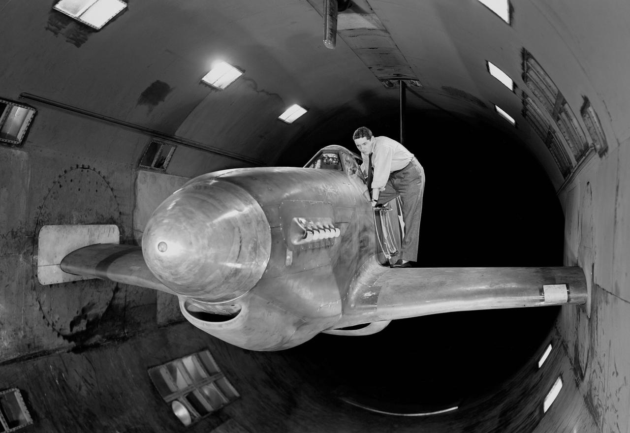
NACA Photographer - North American XP-51B Airplane with outer wing panels removed and ready for testing in Ames 16 foot wind tunnel.
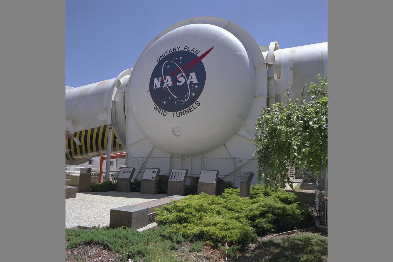
Unitary Plan Wind Tunnel N-227 (new) NASA Logo with Unitary International Historic Mechanical Engineering Landmark commemorative plaques in front. Date: June 16, 1998 Photographer: Tom Trower
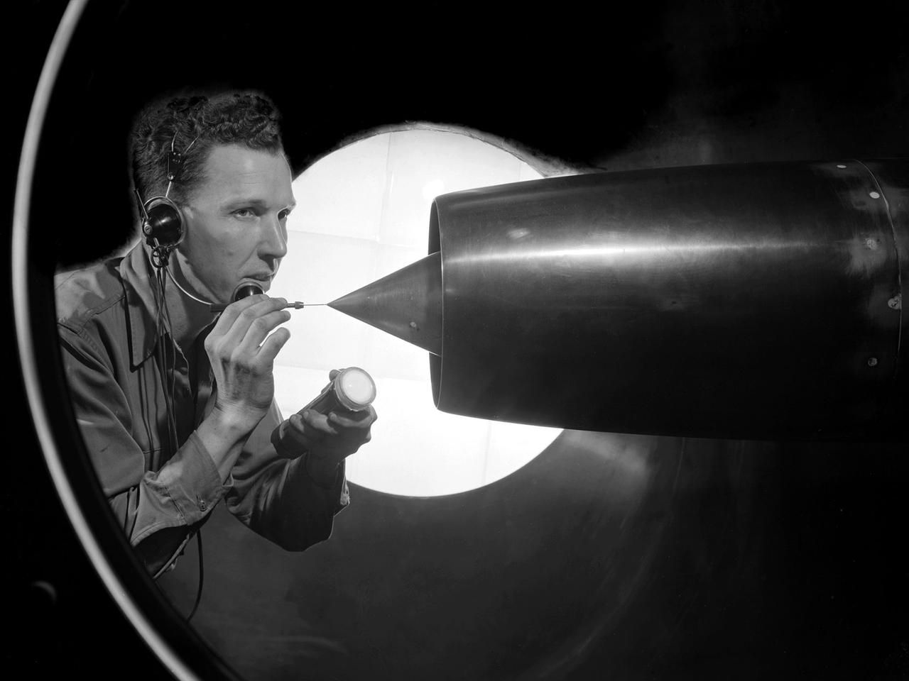
A technician at the National Advisory Committee for Aeronautics (NACA) Lewis Flight Propulsion Laboratory cleans the pitot tube on a 16-inch diameter ramjet in the 8- by 6-Foot Supersonic Wind Tunnel. Pitot tubes are a measurement device used to determine the flow velocity at a specific location in the air stream, not the average velocity of the entire wind stream. NACA Lewis was in the midst of a multi-year program to determine the feasibility of ramjets and design improvements that could be employed for all models. The advantage of the ramjet was its ability to process large volumes of combustion air, resulting in the burning of fuel at the optimal stoichiometric temperatures. This was not possible with turbojets. The higher the Mach number, the more efficient the ramjet operated. The 8- by 6 Supersonic Wind Tunnel had been in operation for just over one year when this photograph was taken. The facility was the NACA’s largest supersonic tunnel and the only facility capable of running an engine at supersonic speeds. The 8- by 6 tunnel was also equipped with a Schlieren camera system that captured the air flow gradient as it passes over the test setup. The ramjet tests in the 8- by 6 tunnel complemented the NACA Lewis investigations using aircraft, the Altitude Wind Tunnel and smaller supersonic tunnels. Researchers studied the ramjet’s performance at different speeds and varying angles -of -attack.
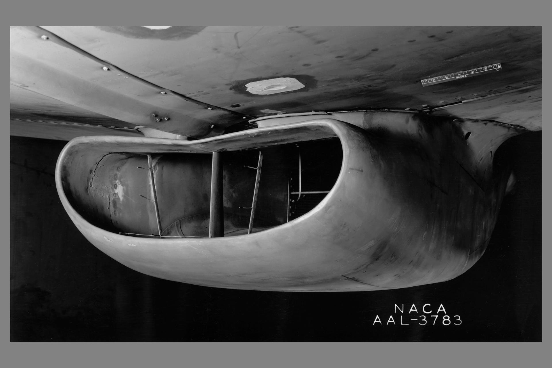
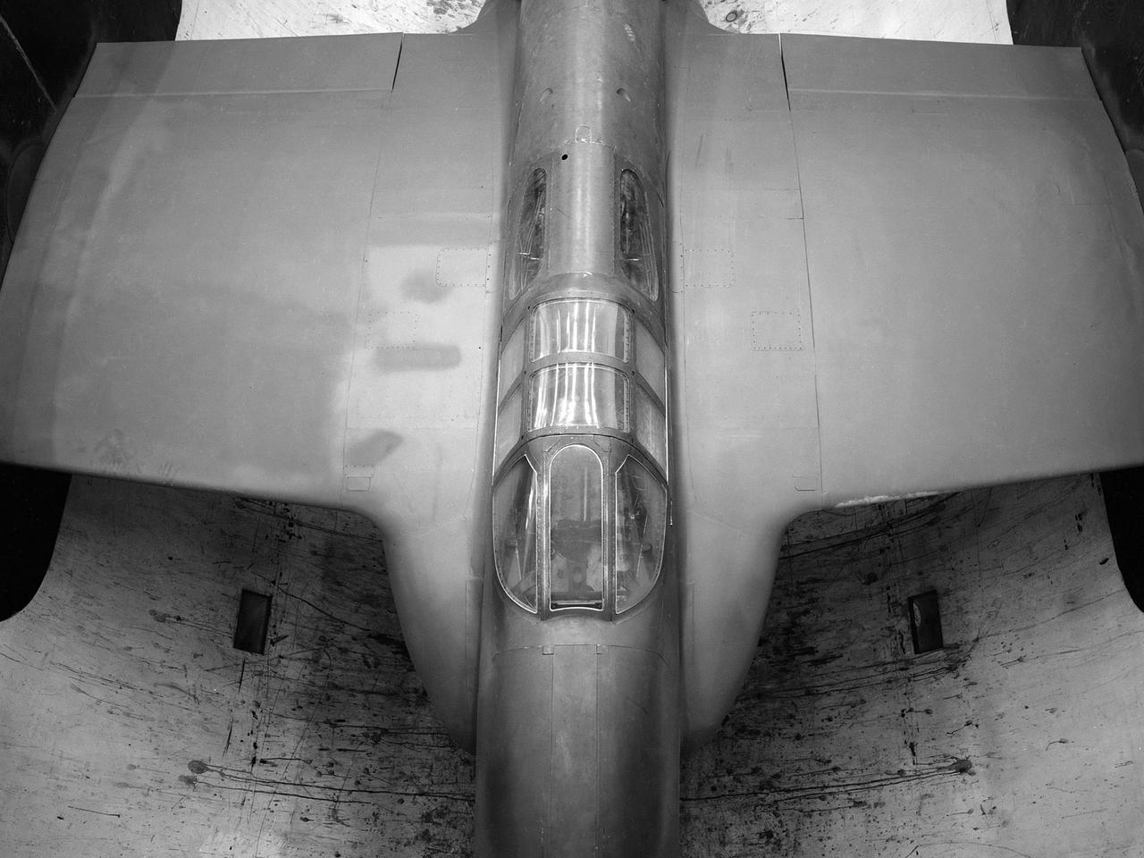
A portion of the North American P-51B airplane was tested in the 16-foot wind tunnel to devise a means of eliminating a rumble which occurred in the radiator duct system. The actual fuselage and center portion of the airplane was installed in the tunnel for this purpose as is shown. A change in the form of the duct was made and tested, which eliminated the rumble. The entrance to the original radiator duct is indicated in this photograph, and the revised form of the duct entrance in photographer AAL-3926.
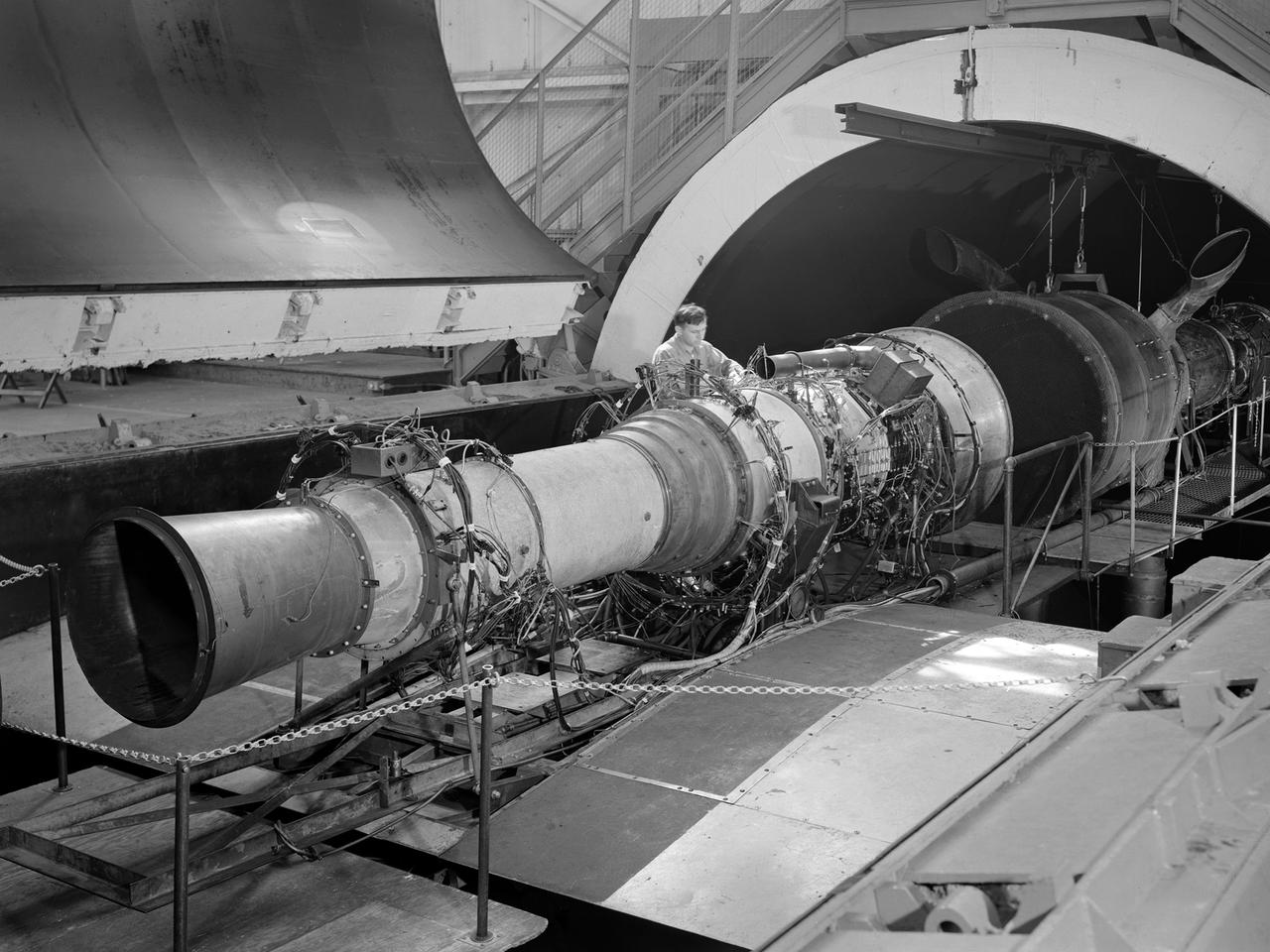
A Rolls Royce Avon RA-14 engine was tested in the Altitude Wind Tunnel at the National Advisory Committee for Aeronautics’ (NACA) Lewis Flight Propulsion Laboratory. The Avon RA-14 engine was a 16-stage axial-flow compressor turbojet capable of producing 9,500 pounds of thrust. The Avon replaced Rolls Royce’s successful Nene engine in 1950 and remained in service until 1974. It was one of several British engines studied in the tunnel during the 1950s. The Altitude Wind Tunnel went through a series of modifications in 1951 to increase its capabilities. An annex was attached to the Exhauster Building to house three new Ingersoll-Rand compressors. The wooden blades on the tunnel’s 31-foot diameter fan were replaced, a pump house and exhaust cooler were constructed underneath the tunnel, and two new cells were added to the cooling tower. The modified wind tunnel continued to analyze jet engines in the 1950s, although the engines, like the RA-14 seen here, were much more powerful than those studied several years before. Lewis researchers studied the RA-14 turbojet engine in the Altitude Wind Tunnel for 11 months in 1956. The engine was mounted on a stand capable of gauging engine thrust, and the tunnel’s air was ducted to the engine through a venturi and bellmouth inlet, seen in this photograph. The initial studies established the engine’s performance characteristics with a fixed-area nozzle and its acceleration characteristics. The researchers also used the tunnel to investigate windmilling of the compressor blades, restarting at high altitudes, and the engine’s performance limits at altitude.
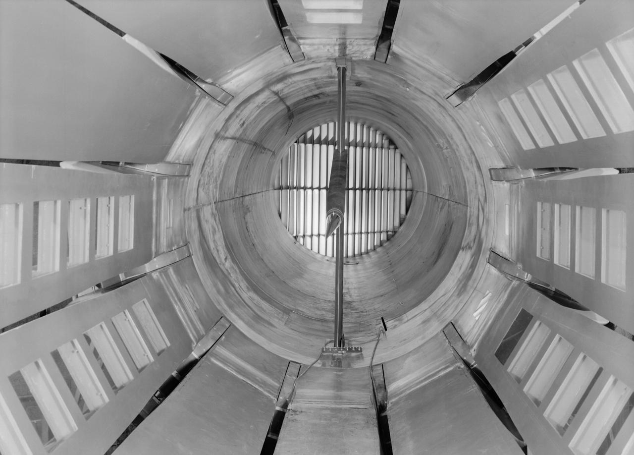
Interior view of the slotted throat test section installed in the 8-Foot High Speed Tunnel (HST) in 1950. The slotted region is about 160 inches in length. In this photograph, the sting-type model support is seen straight on. In a NASA report, the test section is described as follows: The test section of the Langley 8-foot transonic tunnel is dodecagonal in cross section and has a cross-sectional area of about 43 square feet. Longitudinal slots are located between each of the 12 wall panels to allow continuous operation through the transonic speed range. The slots contain about 11 percent of the total periphery of the test section. Six of the twelve panels have windows in them to allow for schlieren observations. The entire test section is enclosed in a hemispherical shaped chamber. John Becker noted that the tunnel s final achievement was the development and use in routine operations of the first transonic slotted throat. The investigations of wing-body shapes in this tunnel led to Whitcomb s discovery of the transonic area rule. James Hansen described the origins of the the slotted throat as follows: In 1946 Langley physicist Ray H. Wright conceived a way to do transonic research effectively in a wind tunnel by placing slots in the throat of the test section. The concept for what became known as the slotted-throat or slotted-wall tunnel came to Wright not as a solution to the chronic transonic problem, but as a way to get rid of wall interference (i.e., the mutual effect of two or more meeting waves or vibrations of any kind caused by solid boundaries) at subsonic speeds. For most of the year before Wright came up with this idea, he had been trying to develop a theoretical understanding of wall interference in the 8-Foot HST, which was then being repowered for Mach 1 capability. When Wright presented these ideas to John Stack, the response was enthusiastic but neither Wright nor Stack thought of slotted-throats as a solution to the transonic problem, only the wall interference problem. It was an accidental discovery which showed that slotted throats might solve the transonic problem. Most engineers were skeptical but Stack persisted. Initially, plans were to modify the 16-Foot tunnel but in the spring of 1948, Stack announced that the 8-Foot HST would also be modified. As Hansen notes: The 8-Foot HST began regular transonic operations for research purposes on 6 October 1950. The concept was a success and led to plans for a new wind tunnel which would be known as the 8-Foot Transonic Pressure Tunnel. -- Published in U.S., National Advisory Committee for Aeronautics, Characteristics of Nine Research Wind Tunnels of the Langley Aeronautical Laboratory, 1957, pp. 17, 22 James R. Hansen, Engineer in Charge, NASA SP-4305, p. 454 and Chapter 11, The Slotted Tunnel and the Area Rule.
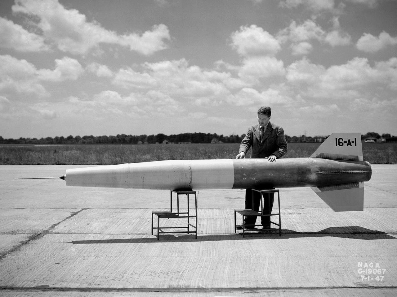
A NACA researcher prepares a 16-inch diameter and 16-foot long ramjet for a launch over Wallops Island in July 1947. The Lewis Flight Propulsion Laboratory conducted a wide variety of studies on ramjets in the 1940s and 1960s to determine the basic operational data necessary to design missiles. Although wind tunnel and test stand investigations were important first steps in determining these factors, actual flight tests were required. Lewis possessed several aircraft for the ramjet studies, including North American F-82 Mustangs, a Northrup P-61 Black Widow, and a Boeing B-29 Superfortress, which was used for this particular ramjet. This was Lewis’ first flight at over the experimental testing ground at Wallops Island. The NACA’s Langley laboratory established the station on the Virginia coast in 1945 to conduct early missile tests. This ramjet-powered missile was affixed underneath the B-29’s left wing and flown up to 29,000 feet. The ramjet was ignited as the aircraft reached Mach 0.5 and released. The flight went well, but a problem with the data recording prevented a successful mission. Nonetheless additional flights in November 1947 provided researchers with data on the engine’s combustion efficiency at different levels of fuel-air ratios, thrust coefficients, temperatures, and drag. Transonic flight data such as the rapid acceleration through varying flight conditions could not be easily captured in wind tunnels.
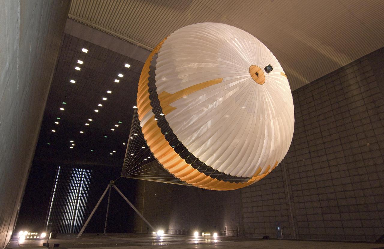
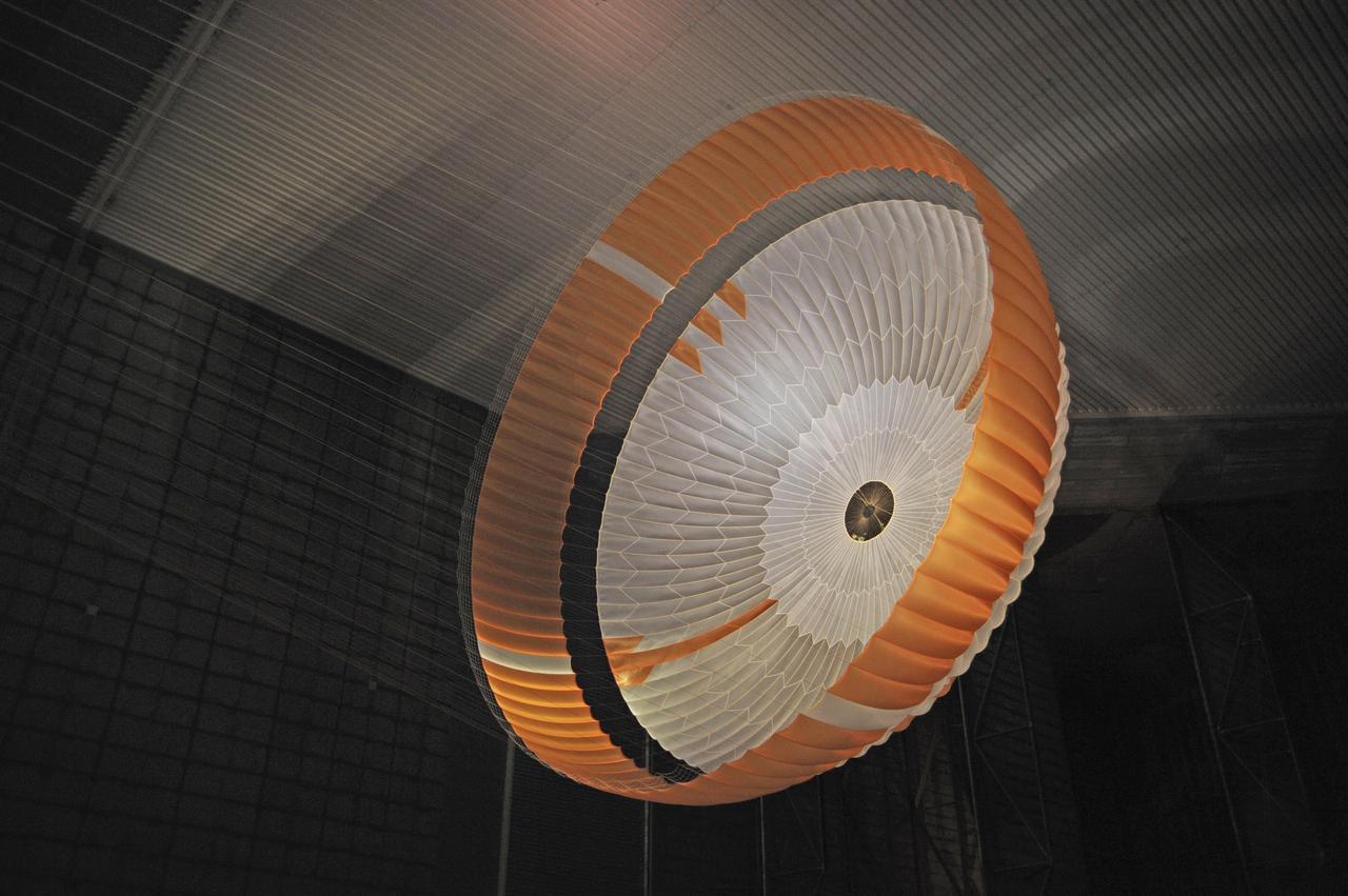
The parachute for NASA next mission to Mars passed flight-qualification testing in March and April 2009 inside the world largest wind tunnel, at NASA Ames Research Center, Moffett Field, Calif. NASA's Mars Science Laboratory mission, to be launched in 2011 and land on Mars in 2012, will use the largest parachute ever built to fly on an extraterrestrial mission. This image shows a duplicate qualification-test parachute inflated in an 80-mile-per-hour (36-meter-per-second) wind inside the test facility. The parachute uses a configuration called disk-gap-band. It has 80 suspension lines, measures more than 50 meters (165 feet) in length, and opens to a diameter of nearly 16 meters (51 feet). Most of the orange and white fabric is nylon, though a small disk of heavier polyester is used near the vent in the apex of the canopy due to higher stresses there. It is designed to survive deployment at Mach 2.2 in the Martian atmosphere, where it will generate up to 65,000 pounds of drag force. The wind tunnel is 24 meters (80 feet) tall and 37 meters (120 feet) wide, big enough to house a Boeing 737. It is part of the National Full-Scale Aerodynamics Complex, operated by the Arnold Engineering Development Center of the U.S. Air Force. http://photojournal.jpl.nasa.gov/catalog/PIA11995
The parachute for NASA Mars Science Laboratory mission opens to a diameter of nearly 16 meters 51 feet. This image shows a duplicate qualification-test parachute inside the world's largest wind tunnel, at NASA Ames Research Center, Moffett Field, Calif. The Mars Science Laboratory will be launched in 2011 for a landing on Mars in 2012. Its parachute is the largest ever built to fly on an extraterrestrial mission. The parachute uses a configuration called disk-gap-band, with 80 suspension lines. Most of the orange and white fabric is nylon, though a small disk of heavier polyester is used near the vent in the apex of the canopy due to higher stresses there. http://photojournal.jpl.nasa.gov/catalog/PIA11994
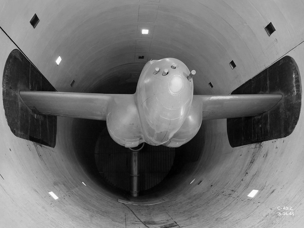
The Altitude Wind Tunnel (AWT) was the National Advisory Committee for Aeronautics (NACA) Aircraft Engine Research Laboratory’s largest and most important test facility in the 1940s. The AWT employed massive cooling and exhaust systems to simulate conditions found at high altitudes. The facility was originally designed to test large piston engines in a simulated flight environment. The introduction of the turbojet during the tunnel’s construction, however, changed the facility’s focus before it became operational. Its first test program was a study of the Bell YP–59A Airacomet and its General Electric I–16 turbojets. The Airacomet was the United States’ first attempt to build a jet aircraft. 1600-horsepower centrifugal engines based on an early design by British engineer Frank Whittle were incorporated into an existing Bell airframe. In October 1942 the Airacomet was secretly test flown in the California desert. The aircraft’s performance was limited, however, and the NACA was asked to study the engines in the AWT. The wind tunnel’s 20-foot-diameter test section was large enough to accommodate entire aircraft with its wing tips and tail removed. The I-16 engines were studied exhaustively in early 1944. They first analyzed the engines in their original configuration and then implemented a boundary layer removal duct, a new nacelle inlet, and new cooling seals. Tests of the modified version showed that the improved distribution of airflow increased the I–16’s performance by 25 percent. The Airacomet never overcame some of its inherent design issues, but the AWT went on to study nearly every emerging US turbojet model during the next decade.
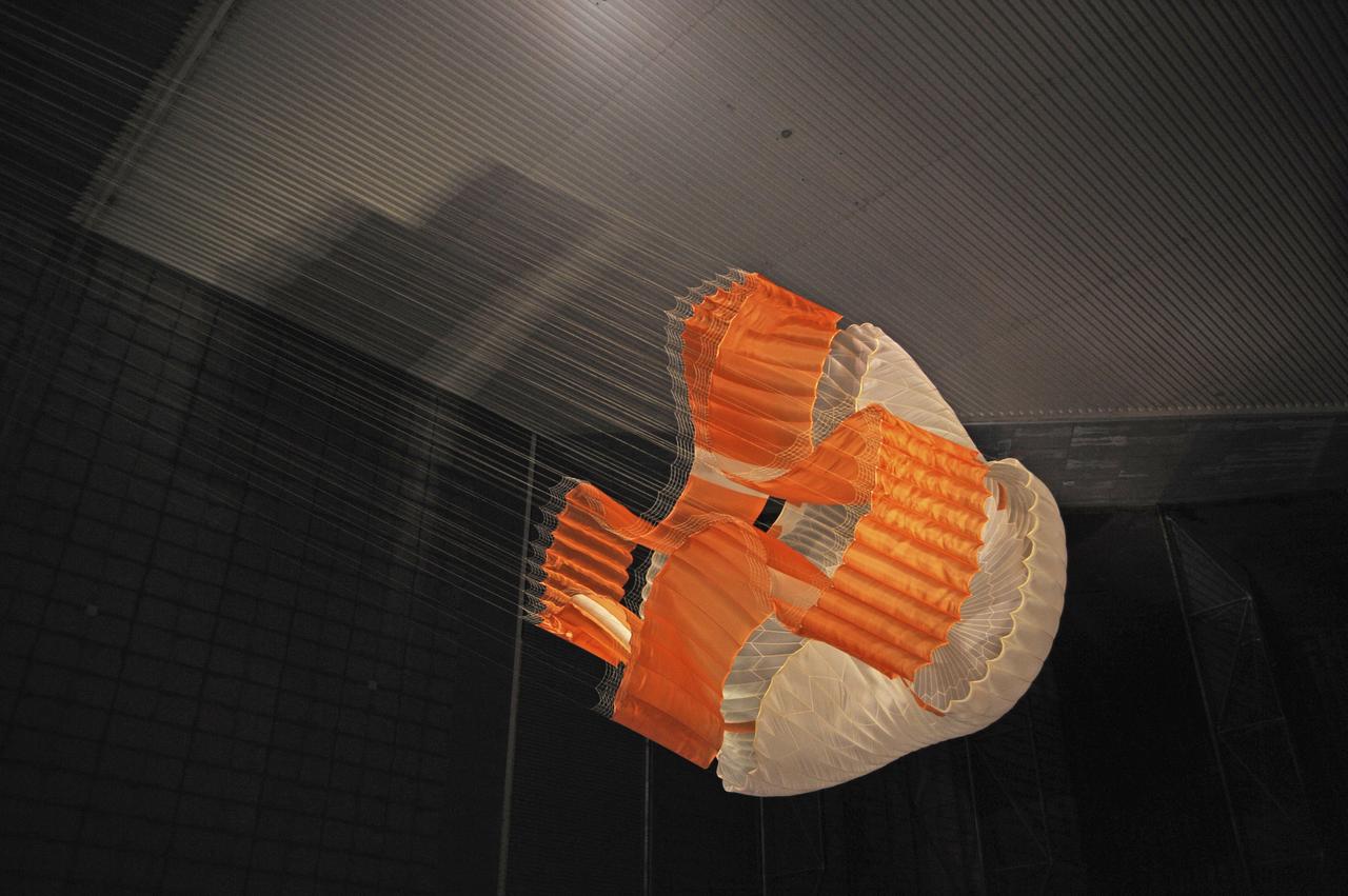
Testing during March and April 2009 inside the world largest wind tunnel, at NASA Ames Research Center, Moffett Field, Calif., qualified the parachute for NASA next Mars rover. The parachute for NASA's Mars Science Laboratory mission, to be launched in 2011 and land on Mars in 2012, is the largest ever built to fly on an extraterrestrial mission. This image shows the qualification-test parachute beginning to open a few seconds after it was launched from a mortar into an 80-mile-per-hour (36-meter-per-second) wind. The parachute uses a configuration called disk-gap-band. It has 80 suspension lines, measures more than 50 meters (165 feet) in length, and opens to a diameter of nearly 16 meters (51 feet). Most of the orange and white fabric is nylon, though a small disk of heavier polyester is used near the vent in the apex of the canopy due to higher stresses there. http://photojournal.jpl.nasa.gov/catalog/PIA11993
Testing during March and April 2009 inside the world largest wind tunnel, at NASA Ames Research Center, Moffett Field, Calif., qualified the parachute for NASA next Mars rover. The parachute for NASA's Mars Science Laboratory mission, to be launched in 2011 and land on Mars in 2012, is the largest ever built to fly on an extraterrestrial mission. This image shows the qualification-test parachute beginning to open a few seconds after it was launched from a mortar into an 80-mile-per-hour (36-meter-per-second) wind. The parachute uses a configuration called disk-gap-band. It has 80 suspension lines, measures more than 50 meters (165 feet) in length, and opens to a diameter of nearly 16 meters (51 feet). Most of the orange and white fabric is nylon, though a small disk of heavier polyester is used near the vent in the apex of the canopy due to higher stresses there. http://photojournal.jpl.nasa.gov/catalog/PIA11992
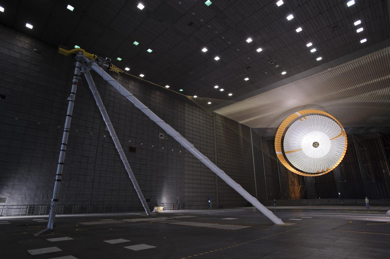
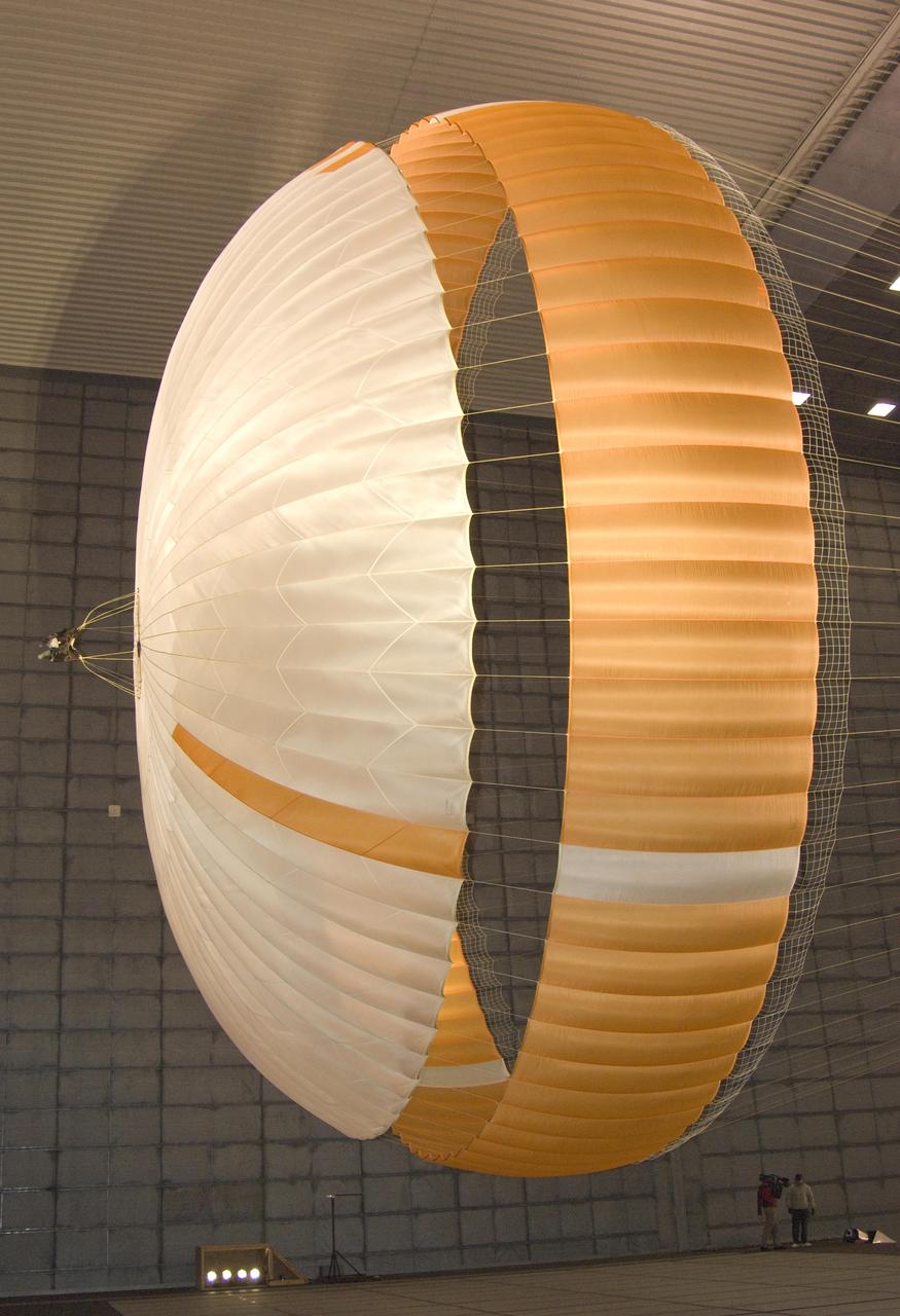
Mars Science Laboratory (MSL) parachuste test in the NASA Ames 80x120ft Subsonic Wind Tunnel at Moffett Field, Calif. (TR #22 - Phase 6) is the largest ever built to fly on an extraterrestrail mission. This image shows a duplicate qualification-test parachute inflated in a 80-mile-per-hour (36-meter-per-second) wind inside the test facility. It has 80 suspension lines, measures more that 50 meers (165 feet) in lenght, and opens to a diameter of nearly 16 meters (51 feet). Most the the orange and white fabric is nylon, though a small disk of heavier polyester is used near the vent in the apex of the canapy due to the higher stresses there. It is designed to survive deployment at Mach 2.2 in the Martian atmosphere, where it will generate up to 65,000 pounds of drag force.
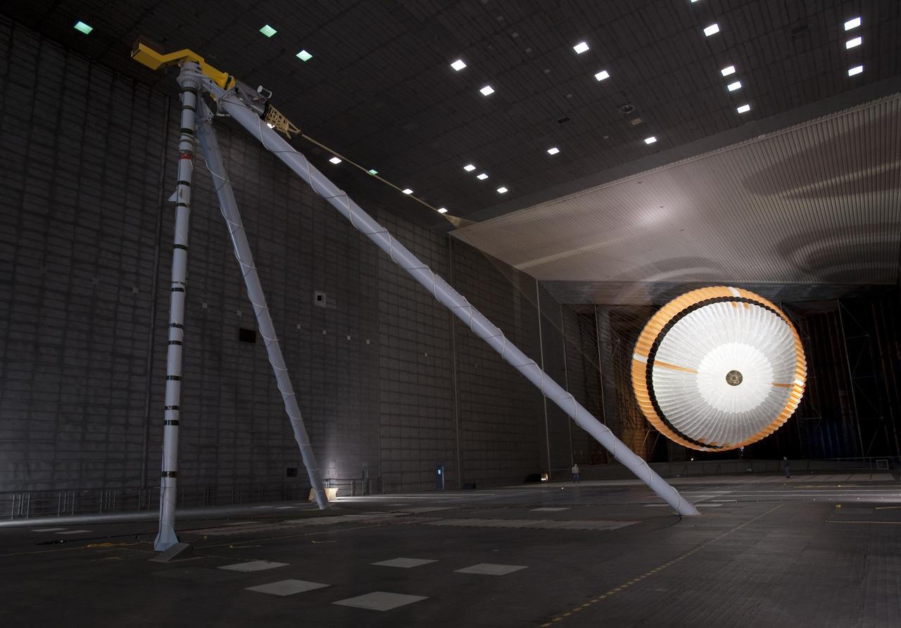
Mars Science Laboratory (MSL) parachuste test in the NASA Ames 80x120ft Subsonic Wind Tunnel at Moffett Field, Calif. (TR #22 - Phase 6) is the largest ever built to fly on an extraterrestrail mission. This image shows a duplicate qualification-test parachute inflated in a 80-mile-per-hour (36-meter-per-second) wind inside the test facility. It has 80 suspension lines, measures more that 50 meers (165 feet) in lenght, and opens to a diameter of nearly 16 meters (51 feet). Most the the orange and white fabric is nylon, though a small disk of heavier polyester is used near the vent in the apex of the canapy due to the higher stresses there. It is designed to survive deployment at Mach 2.2 in the Martian atmosphere, where it will generate up to 65,000 pounds of drag force.
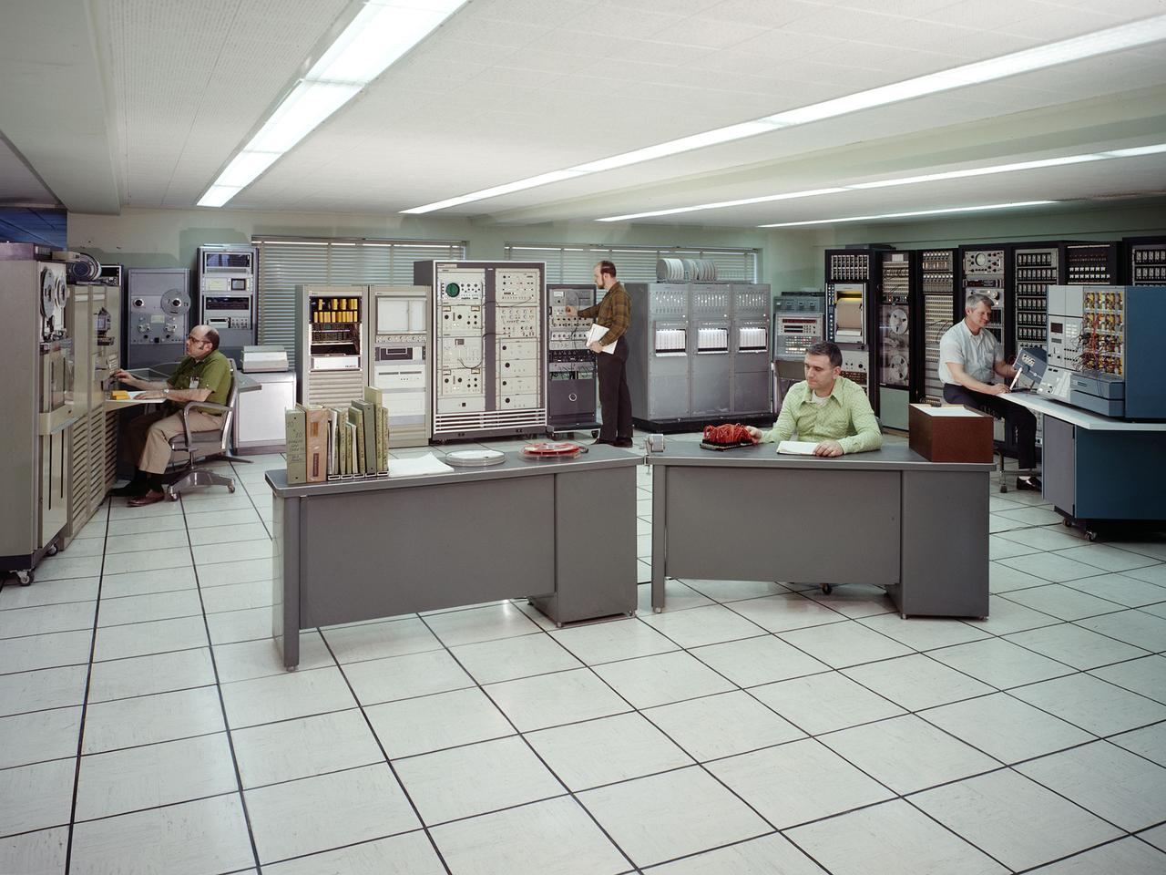
The test data recording equipment located in the office building of the 10-by 10-Foot Supersonic Wind Tunnel at the NASA Lewis Research Center. The data system was the state of the art when the facility began operating in 1955 and was upgraded over time. NASA engineers used solenoid valves to measure pressures from different locations within the test section. Up 48 measurements could be fed into a single transducer. The 10-by 10 data recorders could handle up to 200 data channels at once. The Central Automatic Digital Data Encoder (CADDE) converted this direct current raw data from the test section into digital format on magnetic tape. The digital information was sent to the Lewis Central Computer Facility for additional processing. It could also be displayed in the control room via strip charts or oscillographs. The 16-by 56-foot long ERA 1103 UNIVAC mainframe computer processed most of the digital data. The paper tape with the raw data was fed into the ERA 1103 which performed the needed calculations. The information was then sent back to the control room. There was a lag of several minutes before the computed information was available, but it was exponentially faster than the hand calculations performed by the female computers. The 10- by 10-foot tunnel, which had its official opening in May 1956, was built under the Congressional Unitary Plan Act which coordinated wind tunnel construction at the NACA, Air Force, industry, and universities. The 10- by 10 was the largest of the three NACA tunnels built under the act.
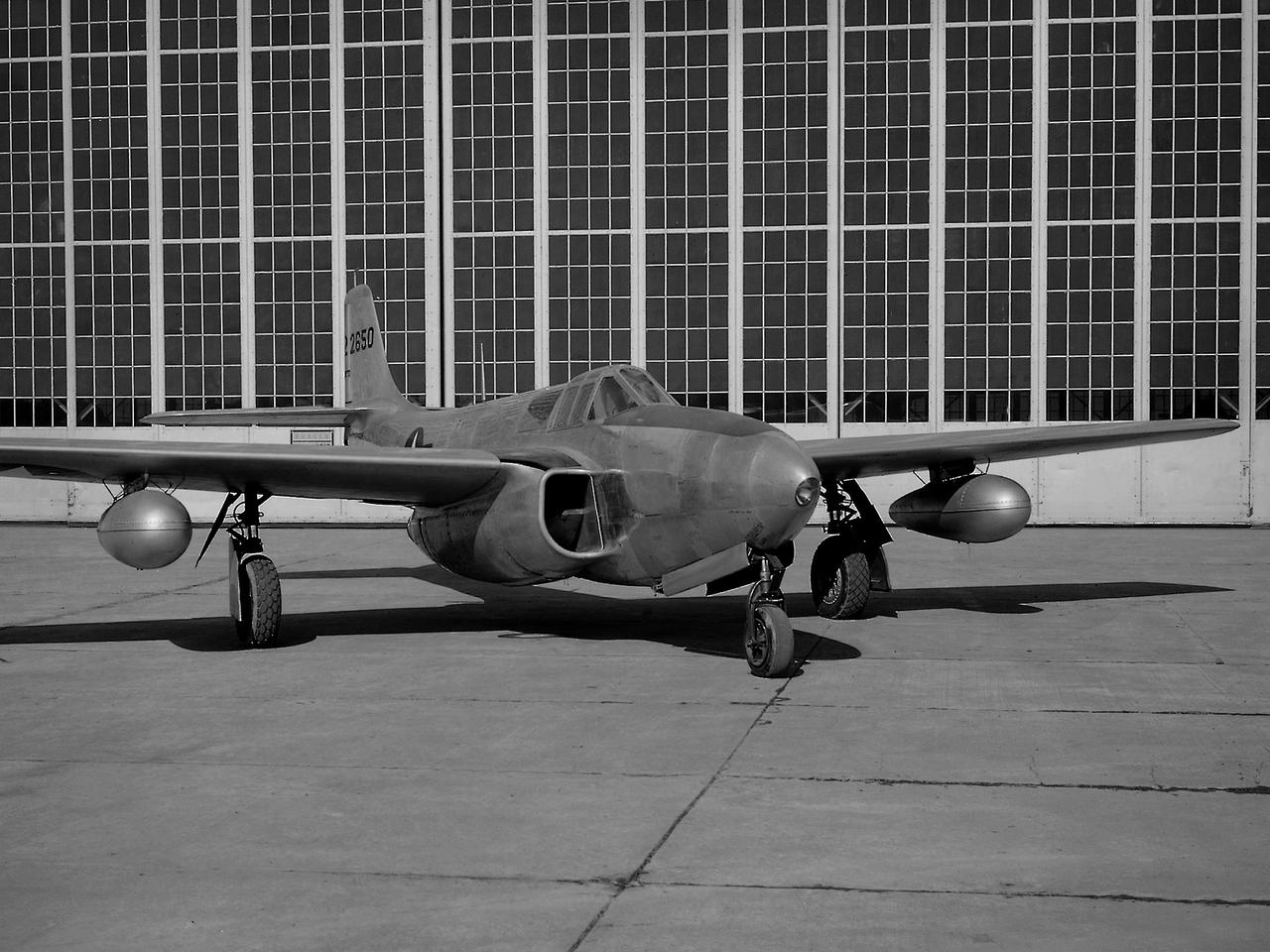
A Bell P-59B Airacomet sits beside the hangar at the National Advisory Committee for Aeronautics (NACA) Lewis Flight Propulsion Laboratory. In 1942 the Bell XP-59A Airacomet became the first jet aircraft in the US. The Airacomet incorporated centrifugal turbojet engines that were based on British plans secretly brought to the US in 1941. A Bell test pilot flew the XP-59A for the first time at Muroc Lake, California in October 1942. The General Electric I-16 engines proved to be problematic. In an effort to increase the engine performance, an Airacomet was secretly brought to Cleveland in early 1944 for testing in the Altitude Wind Tunnel. A series of tunnel investigations in February and March resulted in a 25-percent increase in the I-16 engine’s performance. Nonetheless, Bell’s 66 Airacomets never made it into combat. A second, slightly improved Airacomet, a P-59B, was transferred to NACA Lewis just after the war in September 1945. The P-59B was used over the next three years to study general jet thrust performance and thrust augmentation devices such as afterburners and water/alcohol injection. The P-59B flights determined the proper alcohol and water mixture and injection rate to produce a 21-percent increase in thrust. Since the extra boost would be most useful for takeoffs, a series of ground-based tests with the aircraft ensued. It was determined that the runway length for takeoffs could be reduced by as much as 15 percent. The P-59B used for the tests is now on display at the Air Force Museum at Wright Patterson.
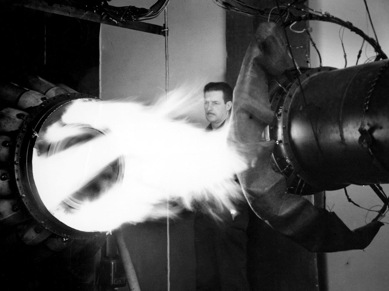
A mechanic watches the firing of a General Electric I-40 turbojet at the National Advisory Committee for Aeronautics (NACA) Lewis Flight Propulsion Laboratory. The military selected General Electric’s West Lynn facility in 1941 to secretly replicate the centrifugal turbojet engine designed by British engineer Frank Whittle. General Electric’s first attempt, the I-A, was fraught with problems. The design was improved somewhat with the subsequent I-16 engine. It was not until the engine's next reincarnation as the I-40 in 1943 that General Electric’s efforts paid off. The 4000-pound thrust I-40 was incorporated into the Lockheed Shooting Star airframe and successfully flown in June 1944. The Shooting Star became the US’s first successful jet aircraft and the first US aircraft to reach 500 miles per hour. NACA Lewis studied all of General Electric’s centrifugal turbojet models during the 1940s. In 1945 the entire Shooting Star aircraft was investigated in the Altitude Wind Tunnel. Engine compressor performance and augmentation by water injection; comparison of different fuel blends in a single combustor; and air-cooled rotors were studied. The mechanic in this photograph watches the firing of a full-scale I-40 in the Jet Propulsion Static Laboratory. The facility was quickly built in 1943 specifically in order to test the early General Electric turbojets. The I-A was secretly analyzed in the facility during the fall of 1943.
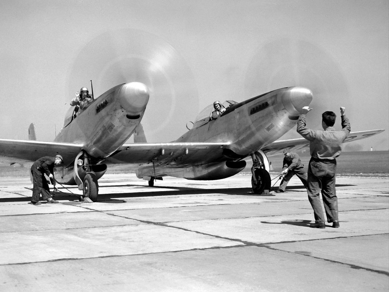
Pilot William Swann, right cockpit, prepares the North American XF-82 Twin Mustang for flight at the National Advisory Committee for Aeronautics (NACA) Lewis Flight Propulsion Laboratory. The aircraft was one of only two prototypes built by North American in October 1945 and powered by Packard Merlin V-1650 piston engines. Over 270 of the F-82 long-distance pursuit fighters were produced during the 1940s. The Mustang’s unique two-pilot configuration allowed one pilot to rest during the long missions and thus be ready for action upon arrival. The NACA took possession of this XF-82 in October 1947. NACA Lewis used the XF-82 as a test bed for ramjet flight tests. Ramjets are continually burning tubes that use the compressed atmospheric air to produce thrust. Ramjets are extremely efficient at high speeds, but rely on some sort of booster to attain that high speed. NACA Lewis undertook an extensive ramjet program in the 1940s that included combustion studies in the Altitude Wind Tunnel, a number of flight tests, and missile drops from aircraft. The 16-inch diameter ramjet missile was fixed to the XF-82 Mustang’s wing and dropped from high altitudes off of Wallops Island. The tests determined the ramjet’s performance and operational characteristics in the transonic range.
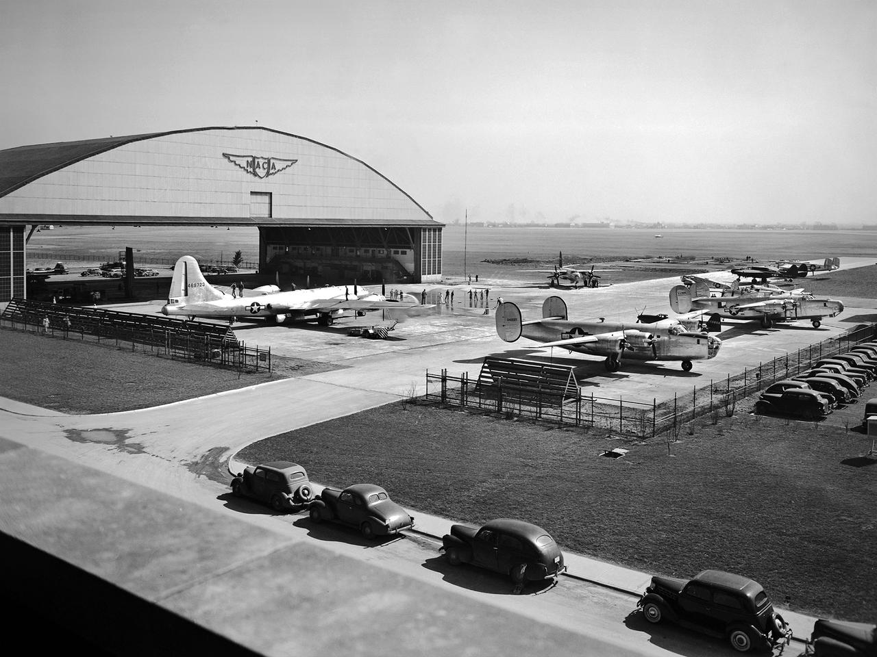
This fleet of military aircraft was used in the 1940s for research at the National Advisory Committee for Aeronautics (NACA) Lewis Flight Propulsion Laboratory in Cleveland, Ohio. The NACA Lewis flight research program was established in March 1943 to augment the lab’s wartime research efforts. NACA Lewis possessed a host of wind tunnels, test stands, and other ground facilities designed to replicate flight conditions, but actual flight tests remained an integral research tool. The military loaned NACA Lewis 15 different aircraft during World War II and six others in the six months following the end of hostilities. During the war these aircraft supported three main efforts: the improved performance of reciprocating engines, better fuel additives and mixtures, and deicing systems. The wartime researchers used the types of aircraft which the studies were intended to improve. After the war the research aircraft served as test beds to investigate engines or systems that often had little to do with the research aircraft. During the war, NACA Lewis’ three pilots were supported by 16 flight engineers, 36 mechanics, and 10 instrumentation specialists. The visible aircraft, from left to right, are a Boeing B-29 Superfortress, a Martin B-26A Marauder, two Consolidated B-24 Liberators, a Cessna UC-78 Bobcat, and a Northrop P-61 Black Widow. Partially obscured are a North American P-51 Mustang, a Bell P-63 King Cobra, a North American AT-6 Texan, and a Lockheed RA-29 Hudson.
The secret test of the Bell YP–59A Airacomet in the spring of 1944 was the first investigation in the National Advisory Committee for Aeronautics (NACA) Aircraft Engine Research Laboratory’s new Altitude Wind Tunnel (AWT). The Airacomet, powered by two General Electric I–A centrifugal turbojets, was the first US jet aircraft. The Airacomet’s 290-miles per hour speed, however, was dwarfed by the German Messerschmitt Me-262 Schwalbe’s 540 miles per hour. In 1941 and 1942 General Electric built the first US jet engines based on technical drawings from British engineer Frank Whittle. Bell Aircraft was contracted to produce an airframe to incorporate the new engines. The result was the Bell XP–59A Airacomet. The aircraft made its first flight over Muroc Lake, California, on October 2, 1942. The aircraft continued to struggle over the next year and the NACA was asked to test it in the new AWT. A Bell YP–59A was flown from the Bell plant in Buffalo to Cleveland by Bob Stanley, who had piloted the first successful flight of the XP–59A at Muroc in 1942. The wing tips and tail were cut from the aircraft so that it would fit into the AWT’s test section. The study first analyzed the engines in their original configuration and then implemented a boundary layer removal duct, a new nacelle inlet, and new cooling seals. Tests of the modified version showed that the improved airflow distribution increased the I–16’s performance by 25 percent. Despite the improved speed, the aircraft was not stable enough to be used in combat, and the design was soon abandoned.

A mechanic works on a General Electric I-40 turbojet at the National Advisory Committee for Aeronautics (NACA) Lewis Flight Propulsion Laboratory. The military selected General Electric’s West Lynn facility in 1941 to secretly replicate the centrifugal turbojet engine designed by British engineer Frank Whittle. General Electric’s first attempt, the I-A, was fraught with problems. The design was improved somewhat with the subsequent I-16 engine. It was not until the engine's next reincarnation as the I-40 in 1943 that General Electric’s efforts paid off. The 4000-pound thrust I-40 was incorporated into the Lockheed Shooting Star airframe and successfully flown in June 1944. The Shooting Star became the US’s first successful jet aircraft and the first US aircraft to reach 500 miles per hour. The NACA’s Lewis Flight Propulsion Laboratory studied all of General Electric’s centrifugal turbojets both during World War II and afterwards. The entire Shooting Star aircraft was investigated in the Altitude Wind Tunnel during 1945. The researchers studied the engine compressor performance, thrust augmentation using a water injection, and compared different fuel blends in a single combustor. The mechanic in this photograph is inserting a combustion liner into one of the 14 combustor cans. The compressor, which is not yet installed in this photograph, pushed high pressure air into these combustors. There the air mixed with the fuel and was heated. The hot air was then forced through a rotating turbine that powered the engine before being expelled out the nozzle to produce thrust.