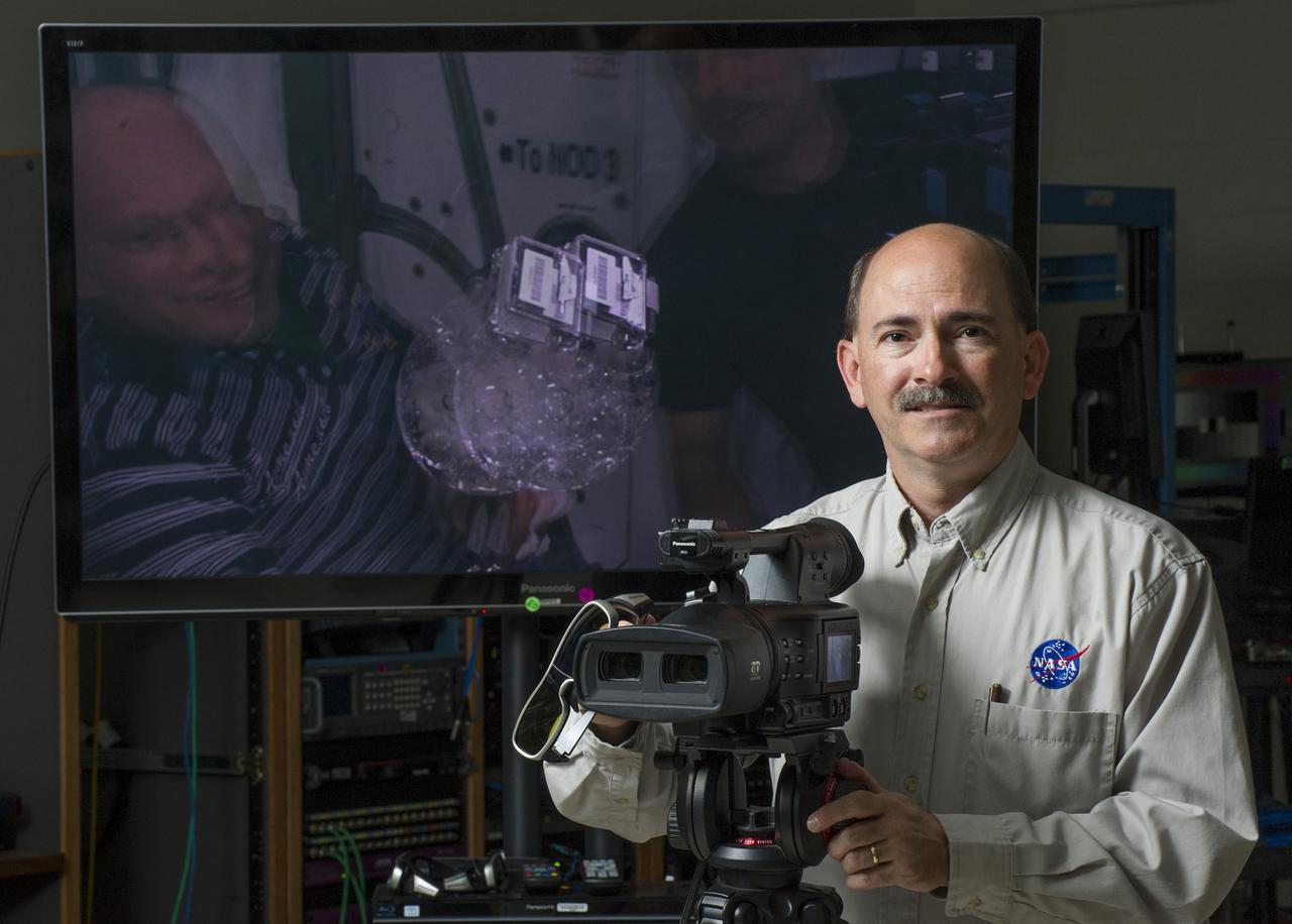
RODNEY GRUBBS, PROGRAM MANAGER FOR NASA'S IMAGERY EXPERTS PROGRAM AT THE MARSHALL SPACE FLIGHT CENTER, DISPLAYS THE 3-D CAMERA THAT WAS RETURNED FROM THE INTERNATIONAL SPACE STATION. THE MONITOR BEHIND HIM SHOWS THE 3-D VIDEO THAT WILL NEED SPECIAL GLASSES TO VIEW CORRECTLY.
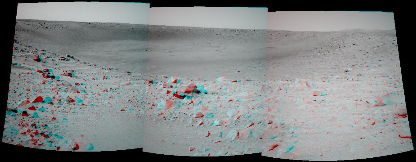
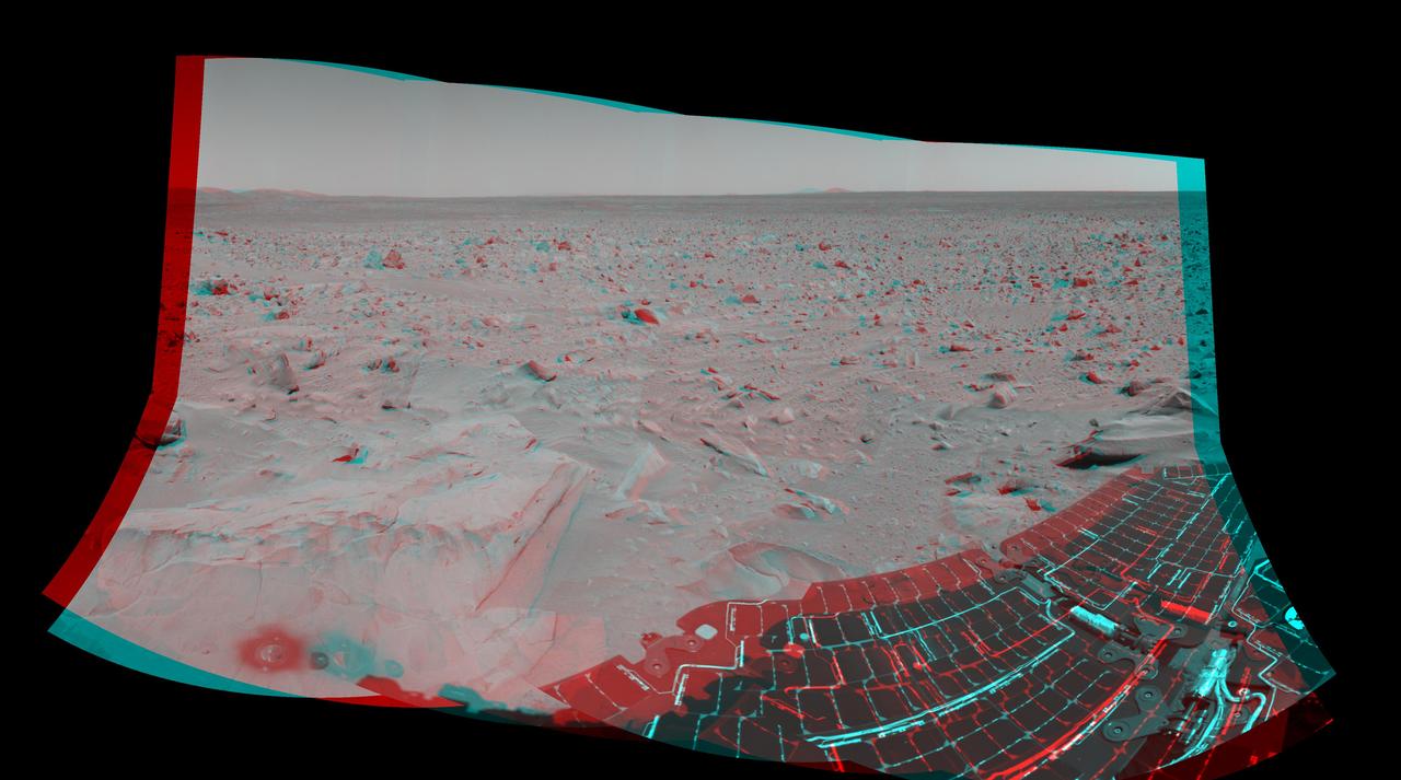
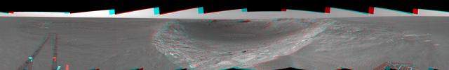
NASA Mars Exploration Rover Spirit took this 3-D navigation camera mosaic of the crater called Bonneville. 3D glasses are necessary to view this image.
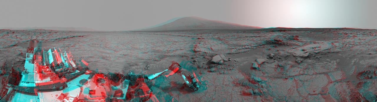
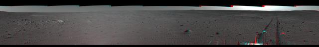
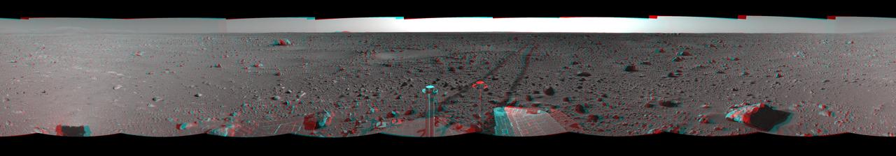
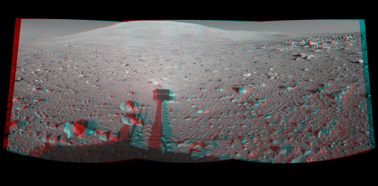
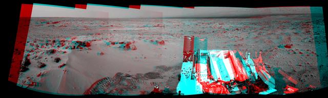
The left and right eyes of the Navigation Camera Navcam in NASA Curiosity Mars rover took the dozens of images combined into this 3-D scene of the rover and its surroundings.
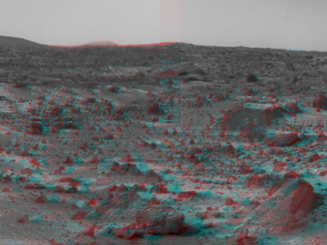
Martian terrain is seen in this 3-D image taken by the panoramic camera on NASA Mars Exploration Rover Spirit. 3D glasses are necessary to view this image.
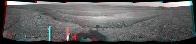
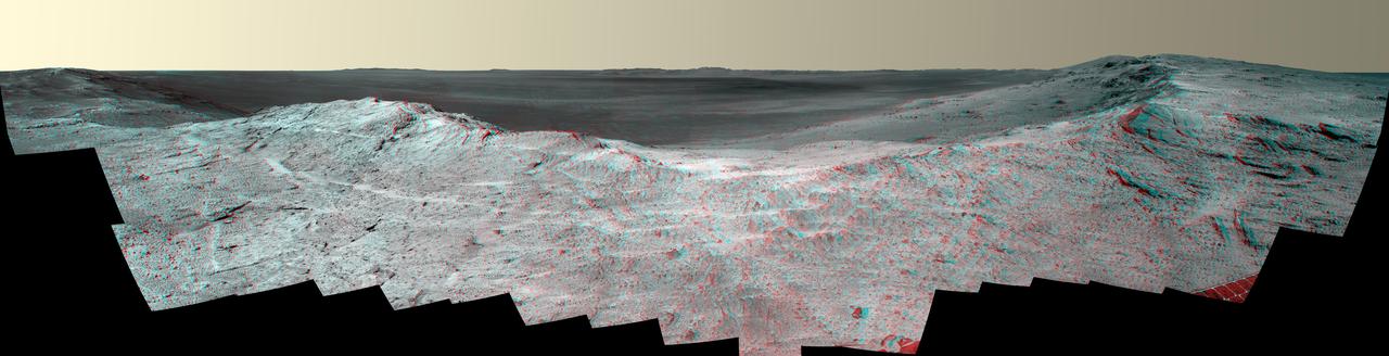
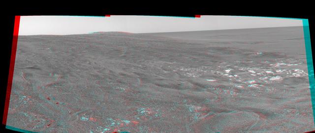
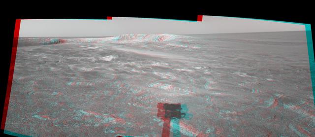
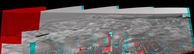
This 3-D view from the navigation camera on NASA Mars Exploration Rover Opportunity shows a vista across Endeavour Crater, with the rover own shadow in the foreground.
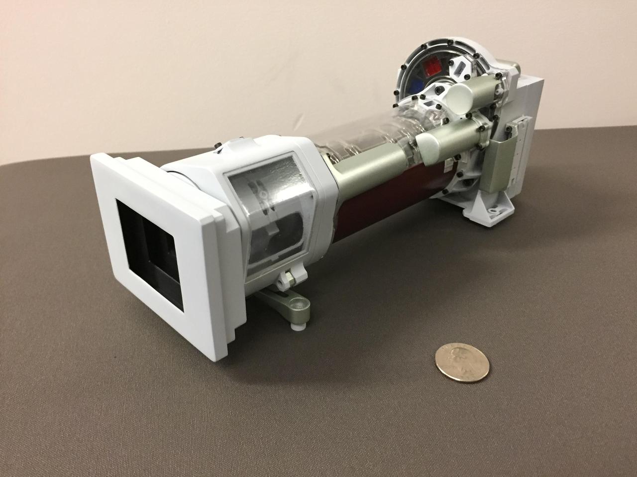
This image shows a 3-D printed model of Mastcam-Z, one of the science cameras on NASA's Mars 2020 rover. Mastcam-Z will include a 3:1 zoom lens. https://photojournal.jpl.nasa.gov/catalog/PIA22101
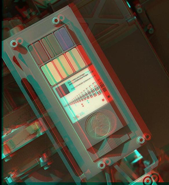
This 3-D view of the calibration target for the MAHLI camera aboard NASA Mars rover Curiosity was assembled from two images taken by that camera during the 34th Martian day. The camera is on the turret of tools at the end of Curiosity robotic arm.

This 3-D cylindrical-perspective mosaic was created from navigation camera images that NASA Mars Exploration Rover Spirit captured on on sol 123. 3D glasses are necessary to view this image.
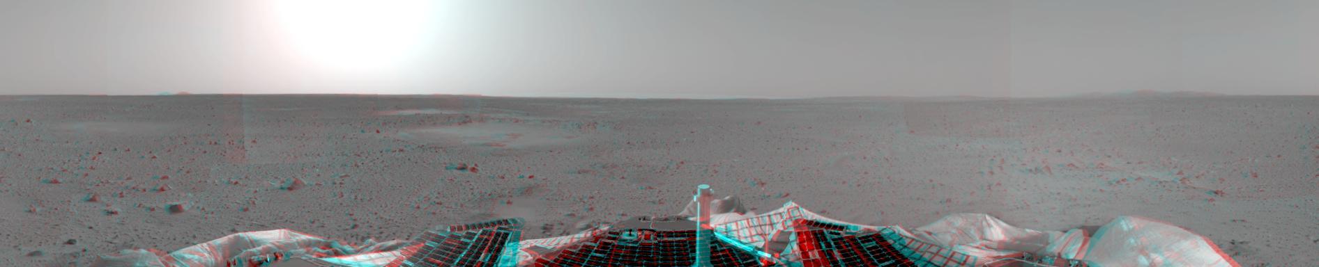
NASA Mars Exploration Rover Spirit took this 3-D navigation camera mosaic of the crater called Bonneville. The rover solar panels can be seen in the foreground. 3D glasses are necessary to view this image.
This 3-D cylindrical-perspective mosaic was created from navigation camera images that NASA Mars Exploration Rover Spirit captured on on sol 121. 3D glasses are necessary to view this image.
NASA Curiosity Mars rover and its tracks are visible in this view combining information from three observations by the HiRISE camera on NASA Mars Reconnaissance Orbiter. You need 3-D glasses to view this image.
This 180-degree 3-D mosaic of images from the navigation camera on the NASA Mars Exploration Rover Opportunity shows the rover close to the outcrop called Copper Cliff, which is in the center of this scene.

This 3-D cylindrical-perspective mosaic was created from navigation camera images that NASA Mars Exploration Rover Spirit captured on on sol 110. 3D glasses are necessary to view this image.
This stereo vista from the panoramic camera Pancam of NASA Mars Exploration Rover Opportunity catches Pillinger Point, on the western rim of Endeavour Crater, in the foreground. You need 3-D glasses to view this image.
This 3-D cylindrical-perspective mosaic was created from navigation camera images that NASA Mars Exploration Rover Spirit captured on on sol 93. 3D glasses are necessary to view this image.
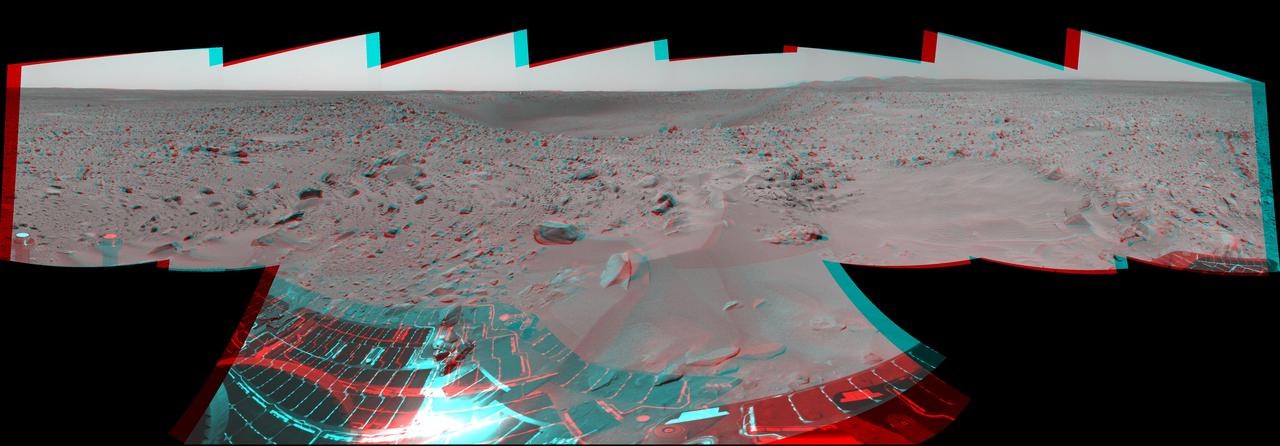
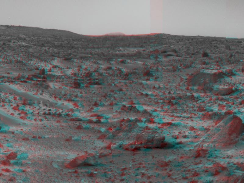
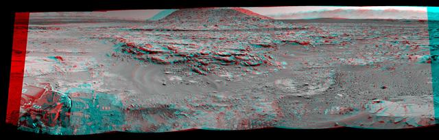
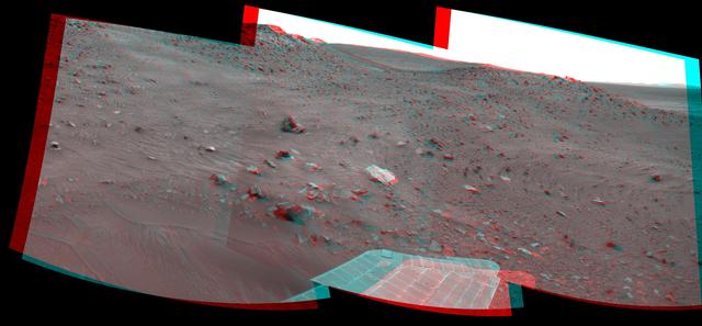
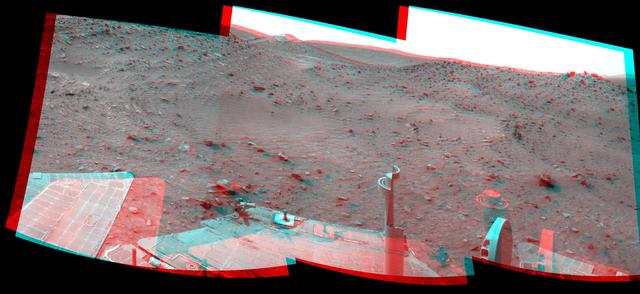
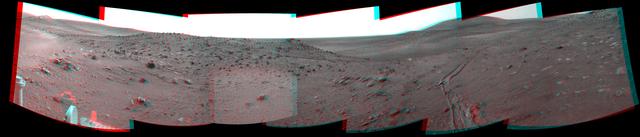
This 3-D cylindrical-perspective mosaic taken by the navigation camera on NASA Mars Exploration Rover Spirit on sol 82 shows the view south of the large crater dubbed Bonneville. 3D glasses are necessary to view this image.
NASA Mars Pathfinder forward rover ramp can be seen successfully unfurled in this image, taken in stereo by the Imager camera. The large rock dubbed Wedge is at lower right. 3-D glasses are necessary to identify surface detail.
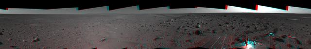
This 3-D cylindrical-perspective mosaic was created from navigation camera images that NASA Mars Exploration Rover Spirit captured on on sol 107. 3D glasses are necessary to view this image.
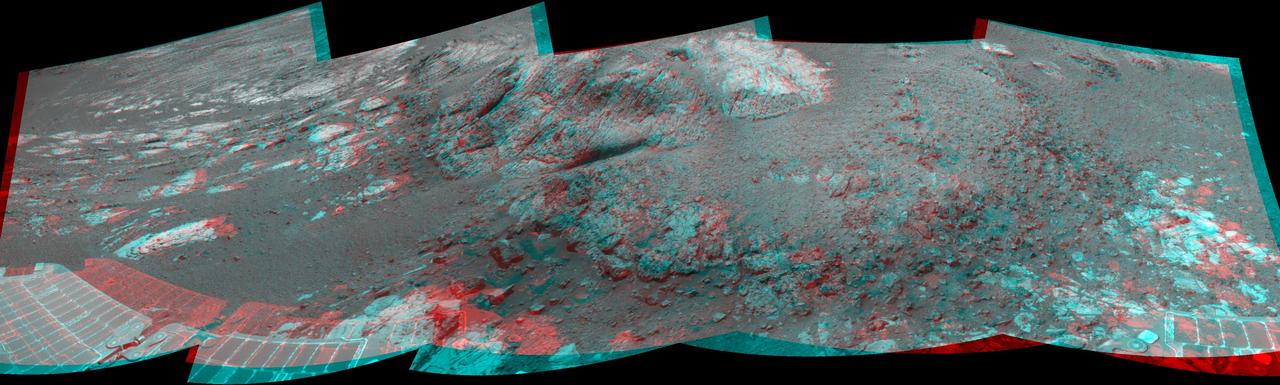
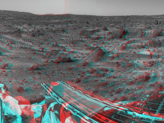
NASA Curiosity Mars rover used its Navigation Camera Navcam on April 11, 2014, to record this stereo scene of a butte called Mount Remarkable and surrounding outcrops. You need 3-D glasses to view this image.
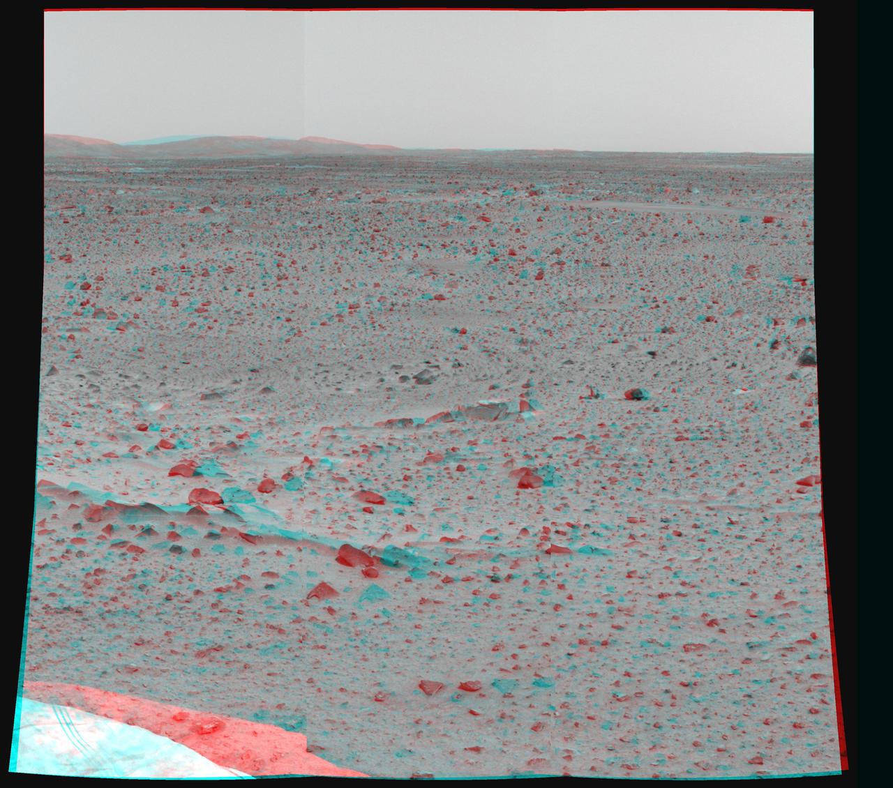
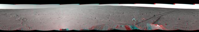
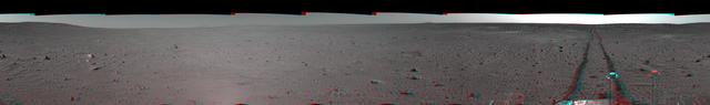
This sprawling look at the martian landscape surrounding the Mars Exploration Rover Spirit is the first 3-D stereo image from the rover navigation camera. Sleepy Hollow can be seen to center left of the image. 3D glasses are necessary.
This 3-D cylindrical-perspective mosaic was created from navigation camera images that NASA Mars Exploration Rover Spirit captured on on sol 122. 3D glasses are necessary to view this image.
NASA Dawn spacecraft obtained this 3-D image of asteroid Vesta with its framing camera on Aug. 23 and 28, 2011 at a distance of 1,700 miles 2,740 kilometers. You will need 3D glasses to view this image.
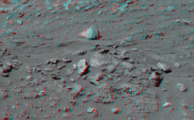
This 3-D image taken by the left and right eyes of the panoramic camera on NASA Mars Exploration Rover Spirit shows the odd rock formation dubbed Cobra Hoods center. 3D glasses are necessary to view this image.
This 3-D cylindrical-perspective mosaic was created from navigation camera images that NASA Mars Exploration Rover Spirit captured on on sol 101. 3D glasses are necessary to view this image.
This 3-D cylindrical-perspective mosaic was created from navigation camera images that NASA Mars Exploration Rover Spirit captured on on sol 109. 3D glasses are necessary to view this image.
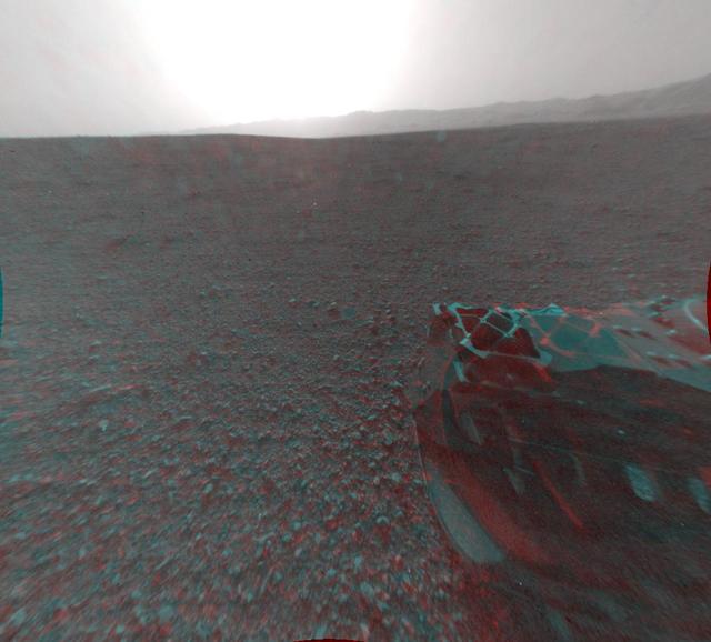
This image is a 3-D view in front of NASA Curiosity rover captured by the rover front left Hazard-Avoidance camera. The image is cropped but part of Mount Sharp is still visible rising above the terrain.
NASA Mars Pathfinder forward rover ramp can be seen successfully unfurled in this image, taken in stereo by the Imager camera. The large rock dubbed Wedge is at lower right. 3-D glasses are necessary to identify surface detail.
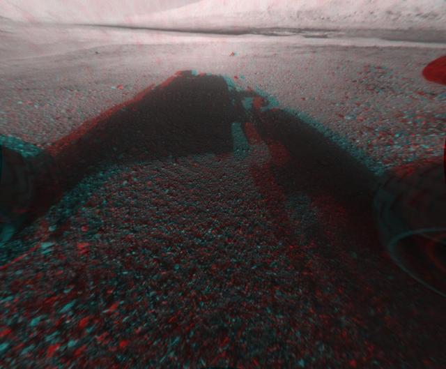
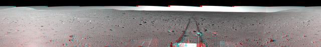
This image is a 3-D view behind NASA Curiosity rover. The anaglyph was made from a stereo pair of Hazard-Avoidance Cameras on the rear of the rover. It has been cropped.
This 3-D cylindrical-perspective mosaic was created from navigation camera images that NASA Mars Exploration Rover Spirit captured on on sol 151. 3D glasses are necessary to view this image.
This 3-D cylindrical-perspective mosaic was created from navigation camera images that NASA Mars Exploration Rover Spirit captured on on sol 108. 3D glasses are necessary to view this image.
This 3-D cylindrical-perspective mosaic was created from navigation camera images that NASA Mars Exploration Rover Spirit captured on on sol 103. 3D glasses are necessary to view this image.
This 3-D cylindrical-perspective mosaic was created from navigation camera images that NASA Mars Exploration Rover Spirit captured on on sol 127. 3D glasses are necessary to view this image.
NASA Mars Pathfinder forward rover ramp can be seen successfully unfurled in this image, taken in stereo by the Imager camera. 3-D glasses are necessary to identify surface detail.
This 3-D cylindrical-perspective mosaic was created from navigation camera images that NASA Mars Exploration Rover Spirit captured on on sol 115. 3D glasses are necessary to view this image.
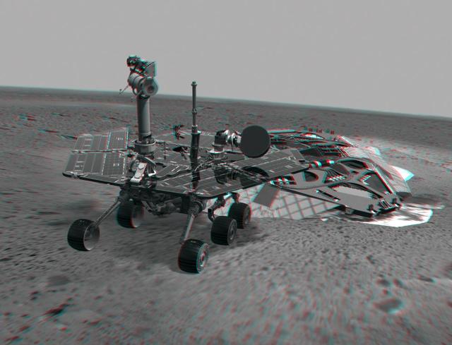
This 3-D image combines computer-generated models of NASA Mars Exploration Rover Spirit and its lander with real surface data from the rover panoramic camera. 3D glasses are necessary to view this image.
This 3-D cylindrical-perspective mosaic was created from navigation camera images that NASA Mars Exploration Rover Spirit captured on on sol 153. 3D glasses are necessary to view this image.
This 3-D cylindrical-perspective mosaic was created from navigation camera images that NASA Mars Exploration Rover Spirit captured on on sol 100. 3D glasses are necessary to view this image.
This 3-D cylindrical-perspective mosaic was created from navigation camera images that NASA Mars Exploration Rover Spirit captured on on sol 124. 3D glasses are necessary to view this image.
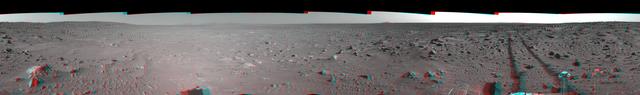
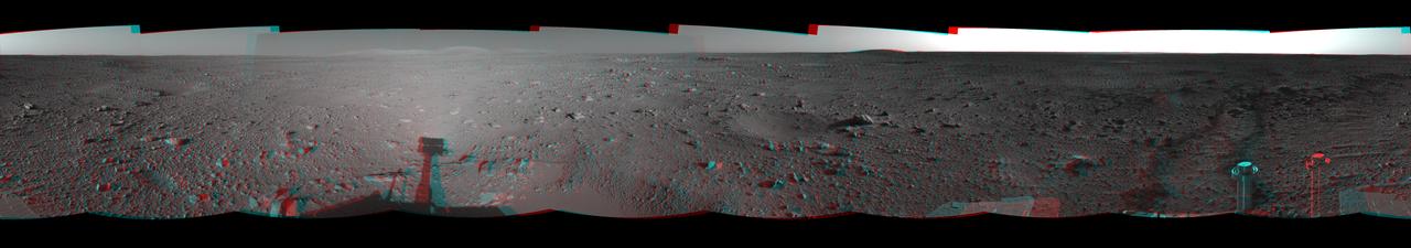
This stereo scene combines frames taken by the navigation camera on NASA Mars Exploration Rover Spirit during the 1,866th Martian day, or sol, of Spirit mission on Mars April 3, 2009. You will need 3-D glasses to view this image.
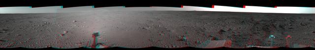
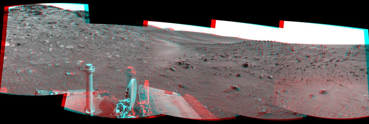
NASA Mars rover Curiosity drove 6.2 feet 1.9 meters during the 100th Martian day, or sol, of the mission Nov. 16, 2012. The rover used its Navigation Camera after the drive to record the images combined into this 3-D panoramic view.
This stereo scene combines frames taken by the navigation camera on NASA Mars Exploration Rover Spirit during the 1,871st Martian day, or sol, of Spirit mission on Mars April 8, 2009. You will need 3-D glasses to view this image.

This image, combining orbital imagery with 3-D modeling, shows flows that appear in spring and summer on a slope inside Mars Newton crater. The source observation was made May 30, 2011, by the HiRISE camera onboard NASA Mars Reconnaissance Orbiter.
This stereo scene combines frames taken by the navigation camera on NASA Mars Exploration Rover Spirit during the 1,869th Martian day, or sol, of Spirit mission on Mars April 6, 2009. You will need 3-D glasses to view this image.
This stereo scene combines frames taken by the navigation camera on NASA Mars Exploration Rover Spirit during the 1,891st Martian day, or sol, of Spirit mission on Mars April 28, 2009. You will need 3-D glasses to view this image.
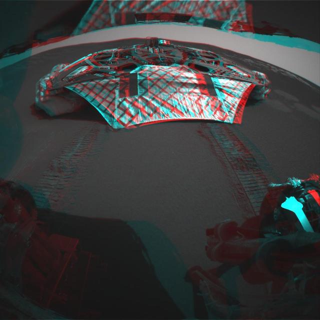
This 3-D image captured by NASA Mars Exploration Rover Opportunity rear hazard-identification camera shows the now-empty lander that carried the rover 283 million miles to Meridiani Planum, Mars. 3D glasses are necessary to view this image.
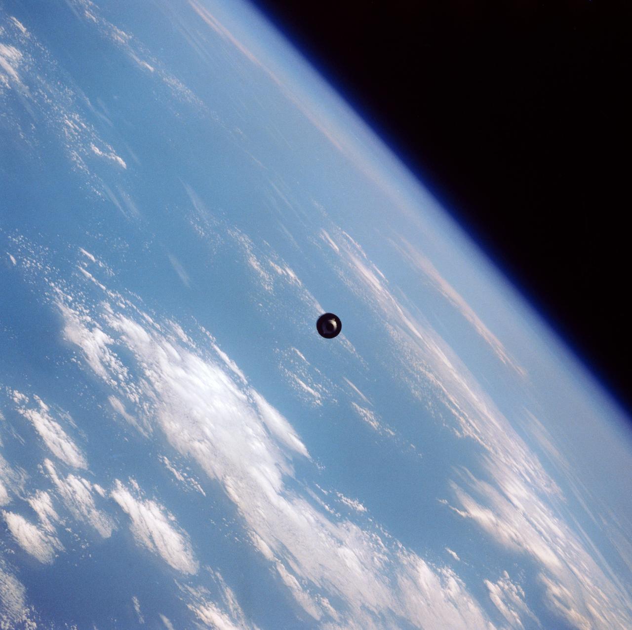
41D-39-068 (1 Sept 1984) --- Quickly moving away from the Space Shuttle Discovery is the Telstar 3 communications satellite, deployed September 1, 1984. The 41-D crew successfully completed three satellite placements, of which this was the last. Telstar was the second 41-D deployed satellite to be equipped with a payload assist module (PAM-D). The frame was exposed with a 70mm camera.
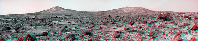
Twin Peaks are modest-size hills to the southwest of NASA Mars Pathfinder landing site. They were discovered on the first panoramas taken by the IMP camera on the 4th of July, 1997. 3D glasses are necessary to identify surface detail.
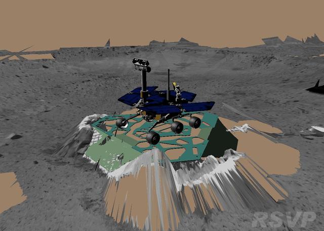
This image shows a screenshot from the software used by engineers to drive the Mars Exploration Rover Spirit. The software simulates the rover's movements across the martian terrain, helping to plot a safe course for the rover. The virtual 3-D world around the rover is built from images taken by Spirit's stereo navigation cameras. Regions for which the rover has not yet acquired 3-D data are represented in beige. This image depicts the state of the rover before it backed up and turned 45 degrees on Sol 11 (01-13-04). http://photojournal.jpl.nasa.gov/catalog/PIA05063
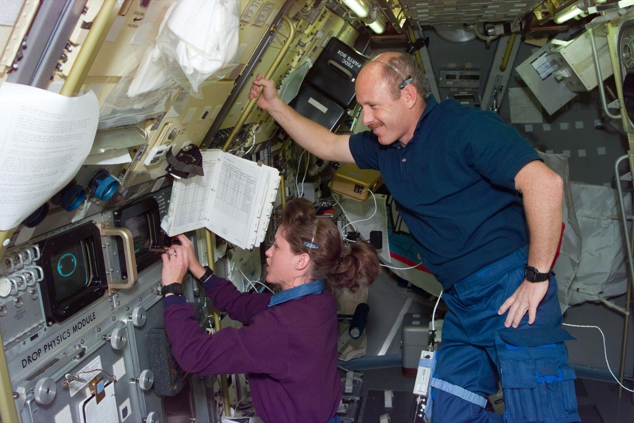
STS073-E-5311 (3 Nov. 1995) --- Astronaut Kathryn C. Thornton, STS-73 payload commander, works at the Drop Physics Module (DPM) on the portside of the science module supporting the U.S. Microgravity Laboratory (USML-2). Astronaut Kenneth D. Bowersox, mission commander, looks on. Five NASA astronauts and two payload specialists are in the last few days of a scheduled 16-day mission. This frame was exposed with the Electronic Still Camera (ESC).

41B-07-230 (S84-27027) (3-11 February 1984) ---Astronaut Robert L. Gibson, 41-B pilot, reviews some teleprinter copy on the flight deck?s starboard station during the eight-day 41-B Space Shuttle mission. Four other astronauts share the Challenger with Gibson. They are Astronauts Vance D. Brand, commander; and Ronald E. McNair, Bruce McCandless II and Robert L. Stewart, all mission specialists. The photograph was taken from the commander?s station with a 35mm camera.
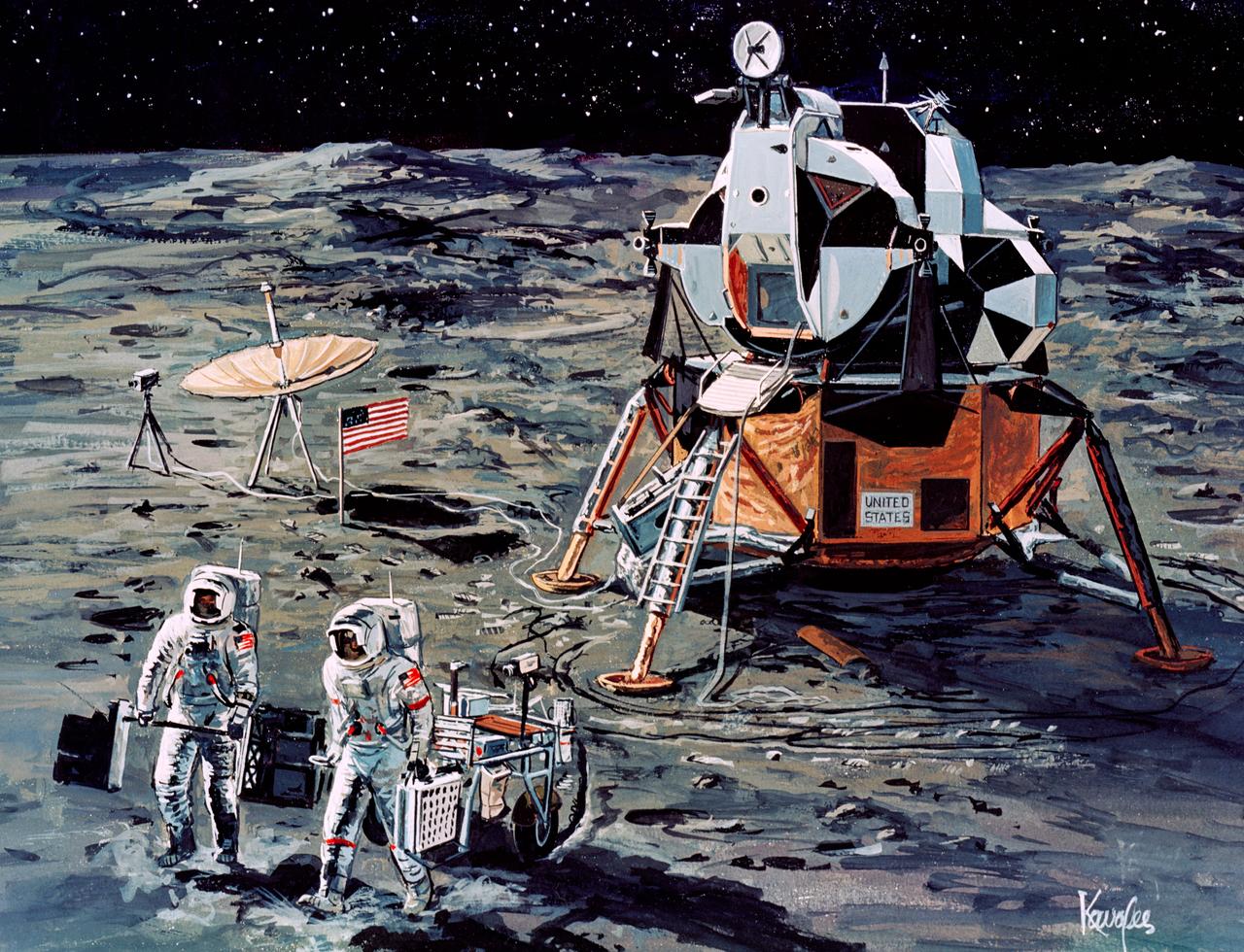
S71-16101 (January 1971) --- A Grumman Aerospace Corporation artist's concept of Apollo 14 crewmen, astronauts Alan B. Shepard Jr., commander, and Edgar D. Mitchell, lunar module pilot, as they set out on their first traverse. Shepard is pulling the Modularized Equipment Transporter (MET) which contains cameras, lunar sample bags, tools and other paraphernalia. Shepard has the Laser Ranging Retro-Reflector (LR-3) in his other hand. Mitchell is carrying the Apollo Lunar Surface Experiments Package (ALSEP) barbell mode.
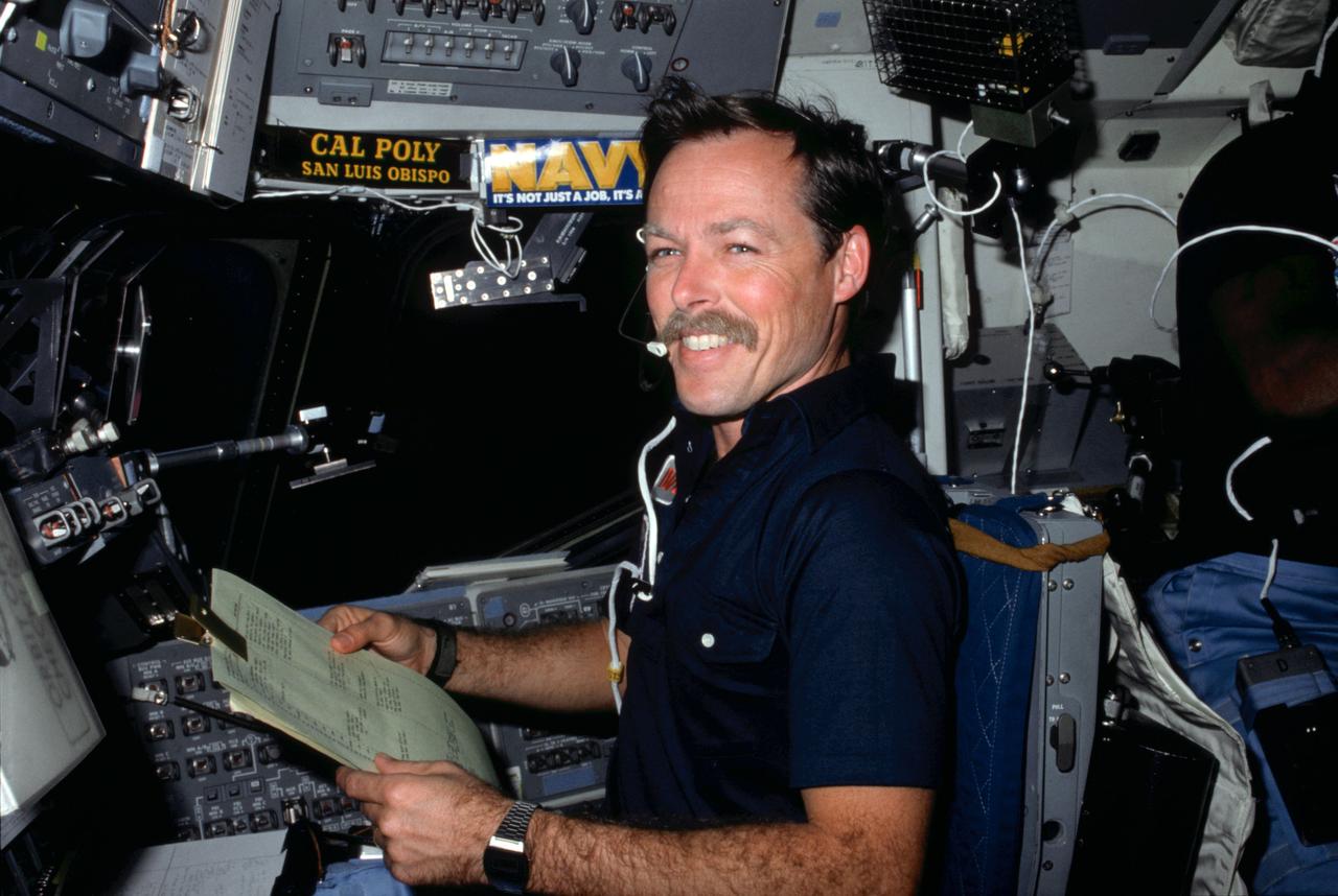
S84-27027 (3-11 Feb 1984) --- Astronaut Robert L. Gibson, STS-41B pilot, reviews some teleprinter copy on the flight deck's starboard station during the eight-day STS-41B Space Shuttle mission. Four other astronauts share the Challenger with Gibson. They are astronauts Vance D. Brand, commander; and Ronald E. McNair, Bruce McCandless II and Robert L. Stewart, all mission specialists. The photograph was taken from the commander's station with a 35mm camera.
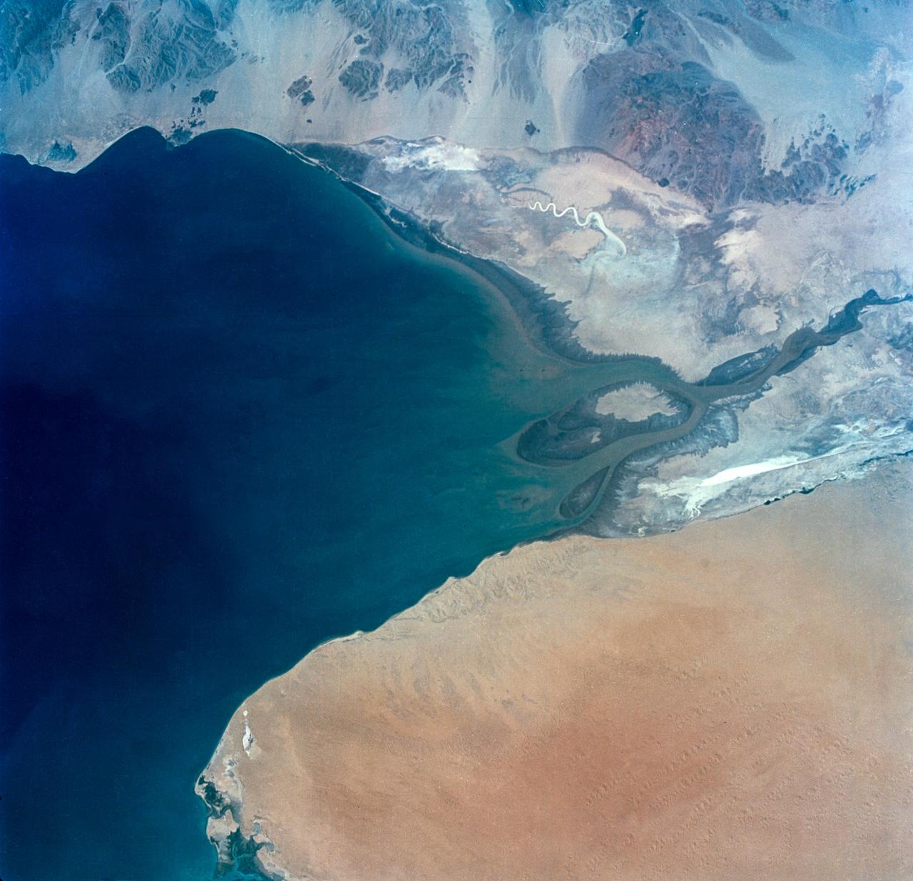
S65-34673 (3-7 June 1965) --- This photograph shows the north end of the Gulf of California at the mouth of the Colorado River as it was seen from the Gemini-4 spacecraft during orbital flight June 3-7, 1965. This picture was part of the Synoptic Terrain Photography experiments conducted during the flight to obtain high quality photographs of large land areas already mapped by aerial photography. In charge of these experiments was Dr. Paul D. Lowman Jr., NASA geologist from Goddard Space Flight Center, Greenbelt, Md. This picture was taken with a modified 70mm Hasselblad camera using Eastman color film, ASA 64 at a lens setting of 250th of a second at f/11.
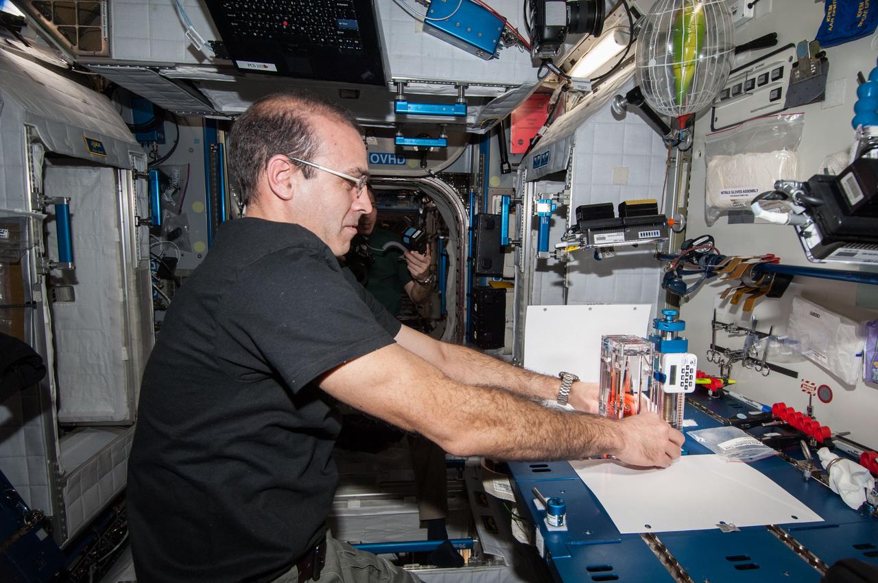
ISS038-E-025002 (3 Jan. 2014) --- NASA astronaut Rick Mastracchio, Expedition 38 flight engineer, conducts a session with the Capillary Flow Experiment (CFE-2) in the Harmony node of the International Space Station. CFE is a suite of fluid physics experiments that investigate how fluids behave in microgravity which could benefit water and fuel delivery systems on future spacecraft. Scientists designed the CFE-2 to study properties of fluids and bubbles inside containers with a specific 3-D geometry. NASA astronaut Mike Hopkins (mostly obscured in the background), flight engineer, uses a still camera to photograph the session.
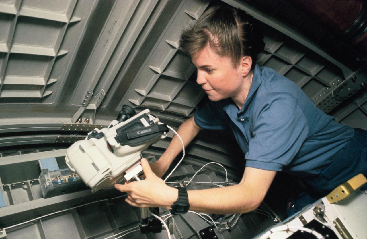
STS063-313-018 (3-11 Feb 1995) --- Janice E. Voss, mission specialist, with a video camera in SpaceHab-3 onboard the Space Shuttle Discovery. This is one of 16 still photographs released by the NASA Johnson Space Center (JSC) Public Affairs Office (PAO) on February 14, 1995. Others onboard the Discovery were astronauts James D. Wetherbee, mission commander; Eileen M. Collins, pilot; Bernard A. Harris Jr., payload commander; mission specialists C. Michael Foale, and cosmonaut Vladimir G. Titov.
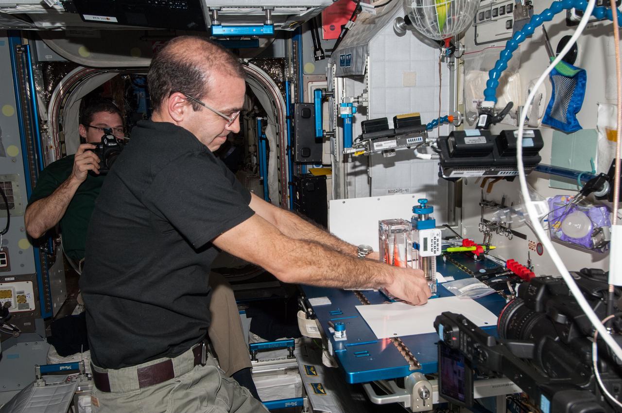
ISS038-E-025002 (3 Jan. 2014) --- NASA astronaut Rick Mastracchio, Expedition 38 flight engineer, conducts a session with the Capillary Flow Experiment (CFE-2) in the Harmony node of the International Space Station. CFE is a suite of fluid physics experiments that investigate how fluids behave in microgravity which could benefit water and fuel delivery systems on future spacecraft. Scientists designed the CFE-2 to study properties of fluids and bubbles inside containers with a specific 3-D geometry. NASA astronaut Mike Hopkins (mostly obscured in the background), flight engineer, uses a still camera to photograph the session.
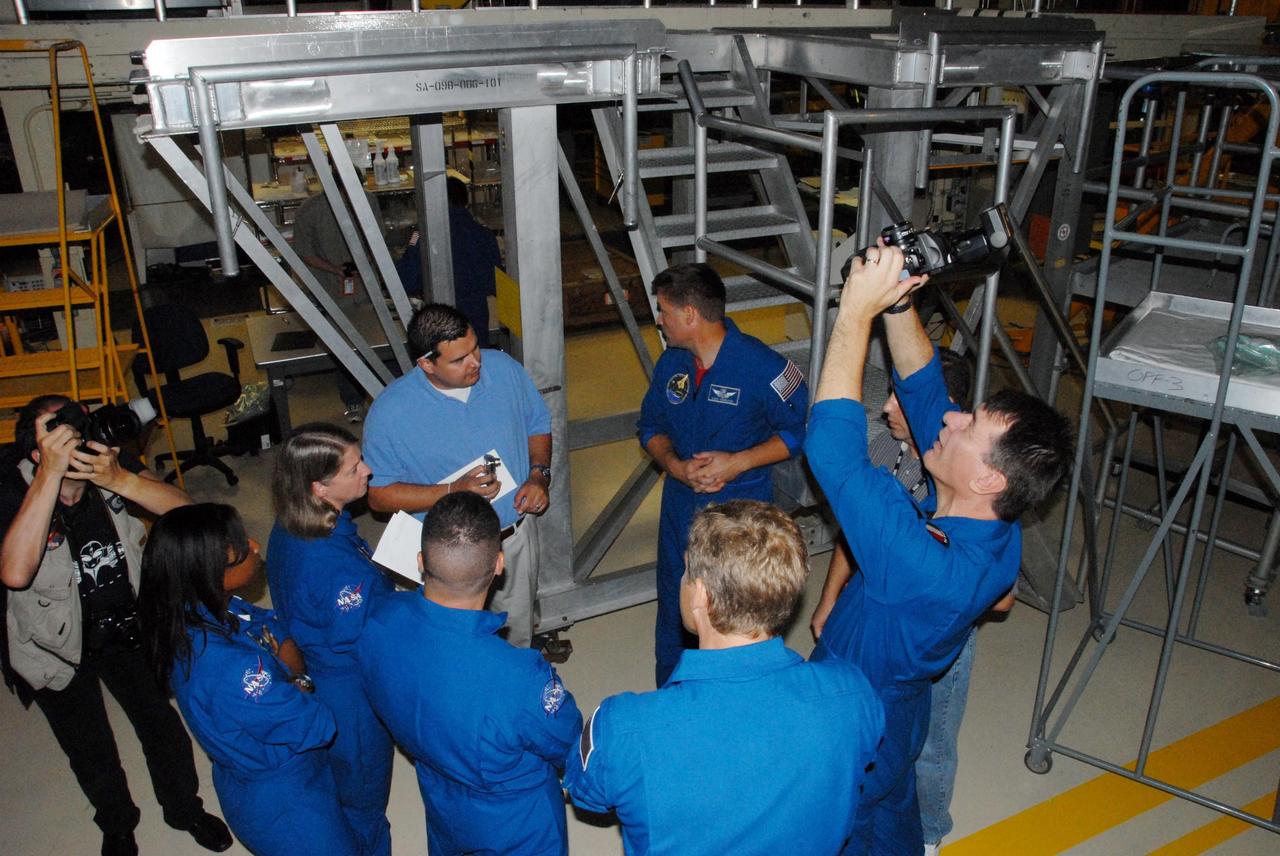
KENNEDY SPACE CENTER, FLA. - The STS-120 crew is at Kennedy for a crew equipment interface test, or CEIT. In Orbiter Processing Facility bay 3, from left in blue flight suits, STS-120 Mission Specialist Stephanie D. Wilson, Commander Pamela A. Melroy, Pilot George D. Zamka, Mission Specialist Scott E. Parazynski (back to camera), Mission Specialist Douglas H. Wheelock and Mission Specialist Paolo A. Nespoli (holding camera), a European Space Agency astronaut from Italy, are given the opportunity to operate the cameras that will fly on their mission. Among the activities standard to a CEIT are harness training, inspection of the thermal protection system and camera operation for planned extravehicular activities, or EVAs. The STS-120 mission will deliver the Harmony module, christened after a school contest, which will provide attachment points for European and Japanese laboratory modules on the International Space Station. Known in technical circles as Node 2, it is similar to the six-sided Unity module that links the U.S. and Russian sections of the station. Built in Italy for the United States, Harmony will be the first new U.S. pressurized component to be added. The STS-120 mission is targeted to launch on Oct. 20. Photo credit: NASA/George Shelton

AS09-26A-3748A (9 March 1969) --- A color infrared photograph of the Salton Sea and Imperial Valley area of Southern California and the Mexicali, Mexico area, taken on March 9, 1969, by one of the four synchronized cameras of the Apollo 9 Earth Resources Survey S065 Experiment. At 2:36 p.m. (EST) when this picture was made the Apollo 9 spacecraft was at an altitude of 103 nautical miles, and the sun elevation was 45 degrees above at which the four-camera combination was aimed was 33 degrees 3 minutes north latitude, and 115 degrees 45 minutes west longitude. The other three cameras used: (B) black and white film with a red filter; (C) black and white infrared film; and (D) black and white film with a green filter.

AS09-26A-3728A (8 March 1969) --- Color infrared photograph of the Houston-Galveston-Freeport, Texas Gulf Coast area taken on March 8, 1969, by one of the four synchronized cameras of the Apollo 9 Earth Resources Survey S065 Experiment. At 3:05 p.m. (EST) when this picture was made the Apollo 9 spacecraft was at an altitude of 105 nautical miles, and the sun elevation was 54 degrees above the horizon. The location of the point on Earth's surface at which the four-camera combination was aimed was 29 degrees 4 minutes north latitude, and 95 degrees 24 minutes west longitude. The three other cameras used: (B) black and white film with a red filter; (C) black and white infrared film; and (D) black and white film with a green filter.
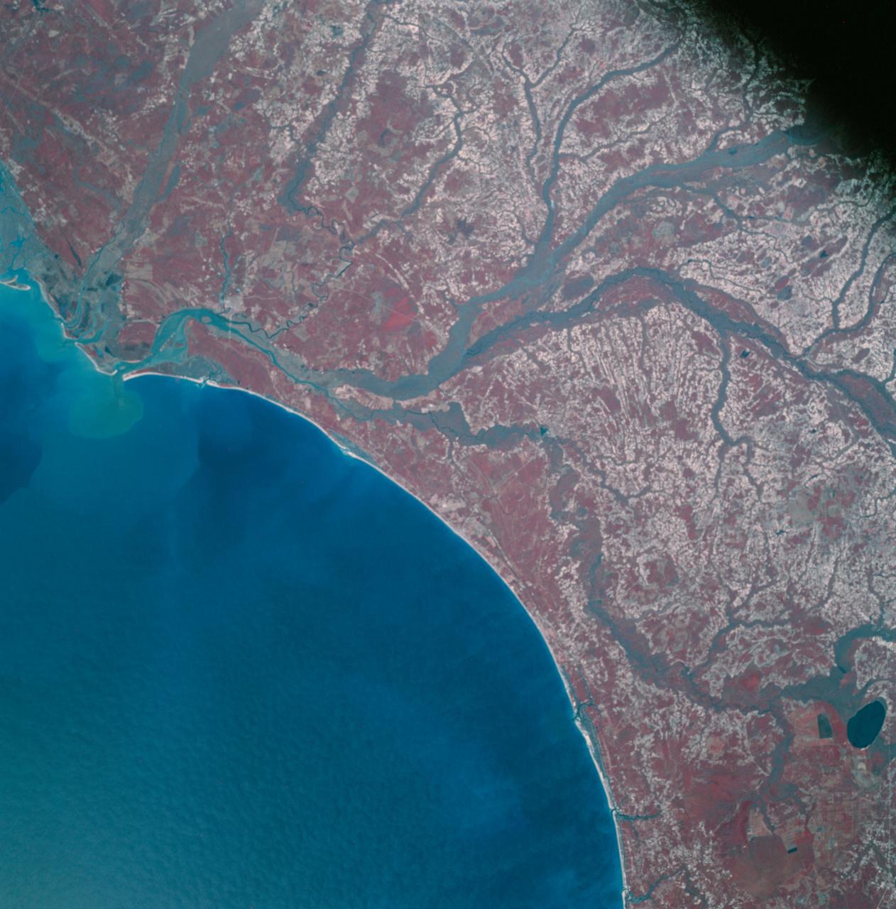
AS09-26A-3793A (12 March 1969) --- Color infrared photograph of the Atlantic Coast of South Carolina, Georgetown-Myrtle Beach-Conway area, taken on March 12, 1969, by one of the four synchronized cameras of the Apollo 9 Earth Resources Survey SO65 Experiment. At 10:00 a.m. (EST) when this picture was made the Apollo 9 spacecraft was at an altitude of 116 nautical miles, and the sun elevation was 39 degrees above the horizon. The location of the point on Earth's surface at which the four-camera combination was aimed was 33 degrees 35 minutes north latitude, and 79 degrees 3 minutes west longitude. The other three cameras used: (B) black and white film with a red filter; (C) black and white infrared film; and (D) black and white film with a green filter.
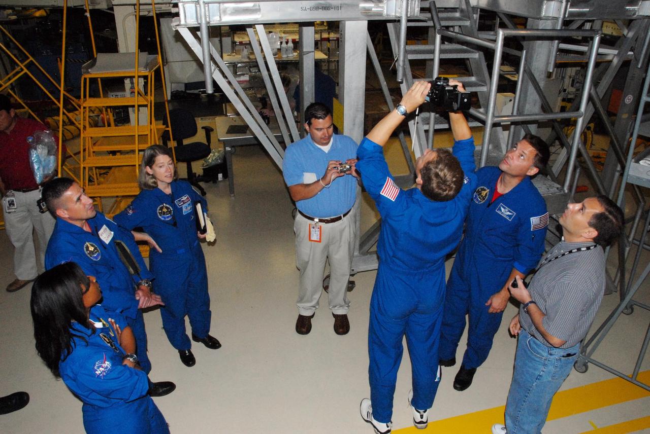
KENNEDY SPACE CENTER, FLA. - The STS-120 crew is at Kennedy for a crew equipment interface test, or CEIT. In Orbiter Processing Facility bay 3, from left in blue flight suits, STS-120 Mission Specialist Stephanie D. Wilson, Pilot George D. Zamka, Commander Pamela A. Melroy, Mission Specialist Scott E. Parazynski (holding camera) and Mission Specialist Douglas H. Wheelock are given the opportunity to operate the cameras that will fly on their mission. Among the activities standard to a CEIT are harness training, inspection of the thermal protection system and camera operation for planned extravehicular activities, or EVAs. The STS-120 mission will deliver the Harmony module, christened after a school contest, which will provide attachment points for European and Japanese laboratory modules on the International Space Station. Known in technical circles as Node 2, it is similar to the six-sided Unity module that links the U.S. and Russian sections of the station. Built in Italy for the United States, Harmony will be the first new U.S. pressurized component to be added. The STS-120 mission is targeted to launch on Oct. 20. Photo credit: NASA/George Shelton
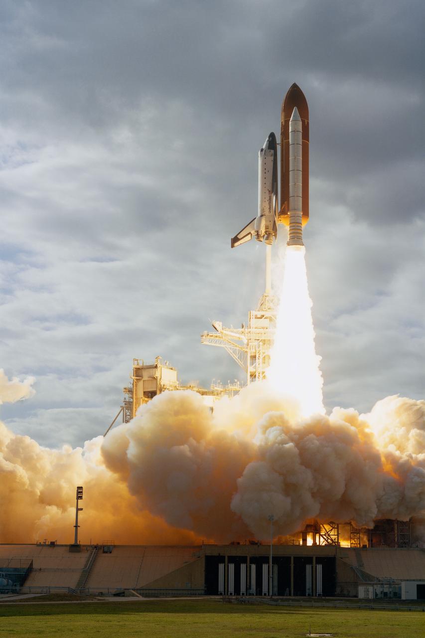
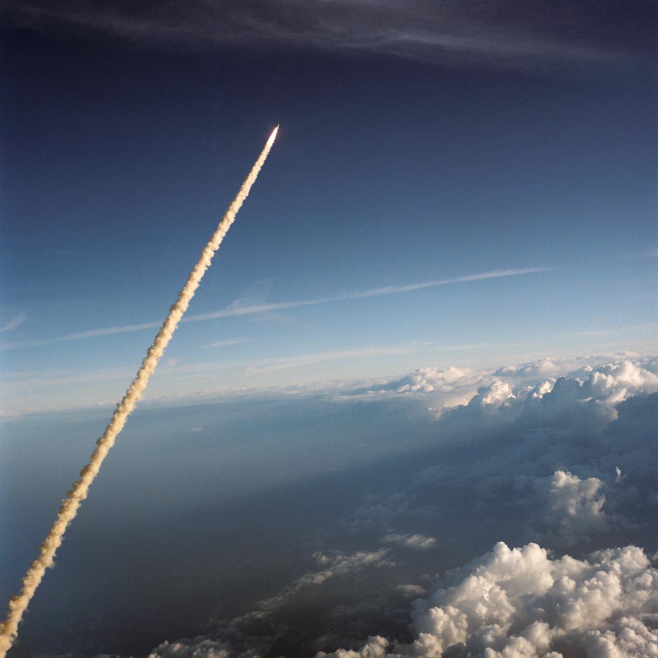
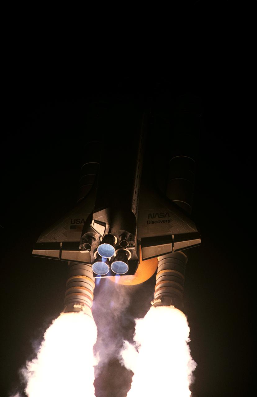
STS080-S-007 (19 Nov. 1996) --- One of the nearest remote camera stations to Launch Pad B captured this profile image of space shuttle Columbia's liftoff from the Kennedy Space Center's (KSC) Launch Complex 39 at 2:55:47 p.m. (EST), November 19, 1996. Onboard are astronauts Kenneth D. Cockrell, mission commander; Kent V. Rominger, pilot; along with Story Musgrave, Tamara E. Jernigan and Thomas D. Jones, all mission specialists. The two primary payloads for STS-80 stowed in Columbia?s cargo bay for later deployment and testing are the Wake Shield Facility (WSF-3) and the Orbiting and Retrievable Far and Extreme Ultraviolet Spectrometer (ORFEUS) with its associated Shuttle Pallet Satellite (SPAS).
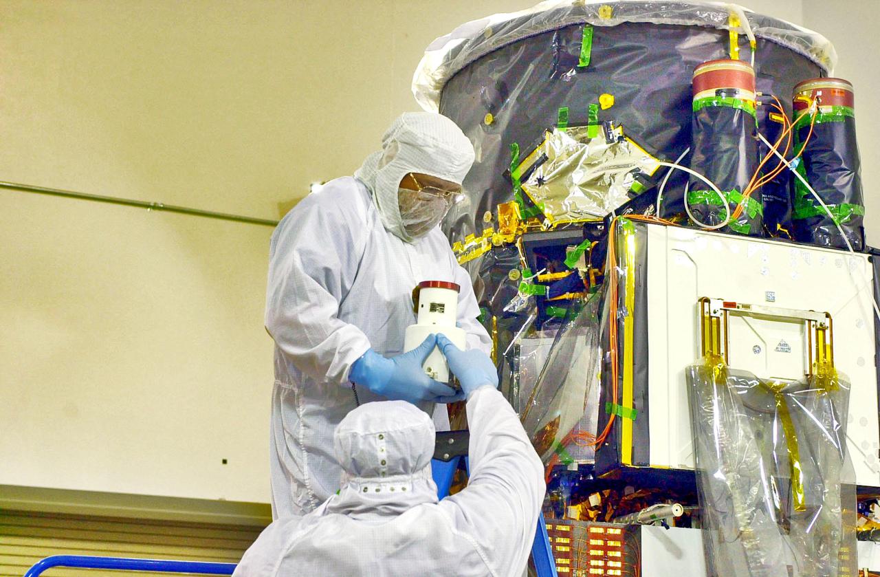
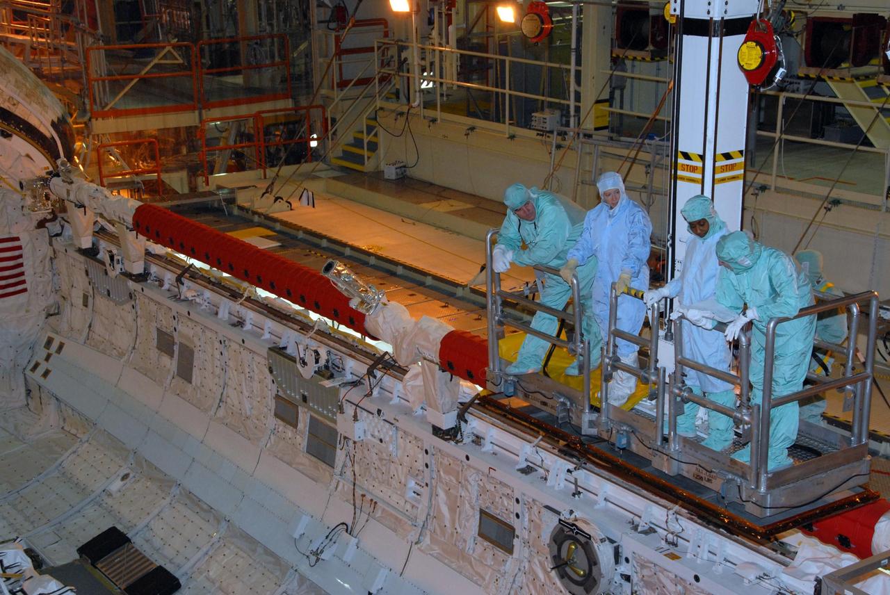
KENNEDY SPACE CENTER, FLA. - Inside the Astrotech Payload Processing Facility on Vandenberg Air Force Base in California, workers hold the Wide Field Camera that they will install on the Cloud-Aerosol Lidar and Infrared Pathfinder Satellite Observation (CALIPSO) spacecraft at right. CALIPSO will fly in combination with the CloudSat satellite to provide never-before-seen 3-D perspectives of how clouds and aerosols form, evolve, and affect weather and climate. CALIPSO and CloudSat will join three other satellites in orbit to enhance understanding of climate systems. The launch date for CALIPSO_CloudSat is no earlier than Aug. 22.
KENNEDY SPACE CENTER, FLA. - Inside the Astrotech Payload Processing Facility on Vandenberg Air Force Base in California, workers prepare a Wide Field Camera for installation on the Cloud-Aerosol Lidar and Infrared Pathfinder Satellite Observation (CALIPSO) spacecraft. CALIPSO will fly in combination with the CloudSat satellite to provide never-before-seen 3-D perspectives of how clouds and aerosols form, evolve, and affect weather and climate. CALIPSO and CloudSat will join three other satellites in orbit to enhance understanding of climate systems. The launch date for CALIPSO_CloudSat is no earlier than Aug. 22.
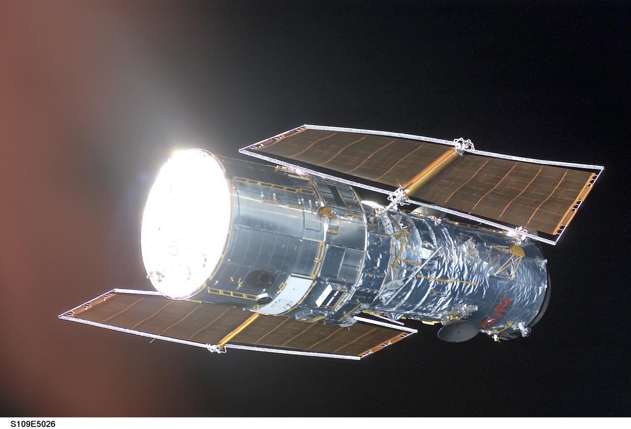
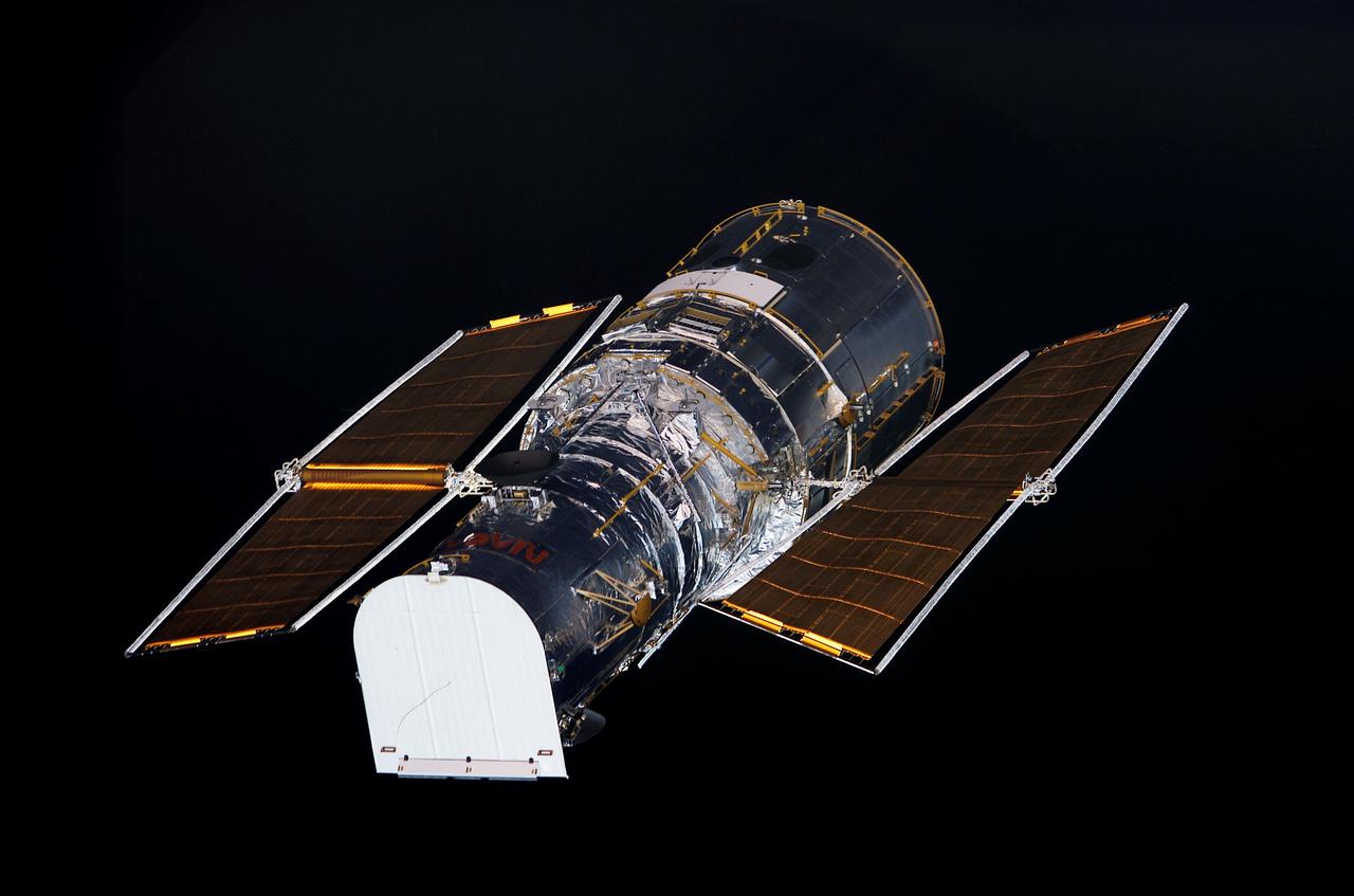
STS109-E-5026 (3 March 2002) --- The Hubble Space Telescope is backdropped against black space as the Space Shuttle Columbia, with a crew of seven astronauts on board, eases closer and closer in order to latch its 50-foot-long robotic arm onto a fixture on the giant telescope. As Columbia flew 350 miles above the Pacific Ocean Southwest of Mexico, with astronaut Nancy J. Currie, mission specialist, in control of the arm and astronaut Scott D. Altman, mission commander, at the controls of the shuttle, the crew went on to capture the Hubble. The image was one of a series recorded with a digital still camera.
S84-26294 (3 Feb 1984) --- This scenic panorama of billowy clouds over the Atlantic and Florida and the contrasting addition of mankind's technology into the picture was provided by astronaut John W. Young and a handheld camera in the cockpit of NASA's Shuttle Training Aircraft (STA) moments after the 226 tons of spacecraft hardware were lifted off Kennedy Space Center's (KSC) Launch Pad 39A. Inside the Space Shuttle Challenger (STS 41-B), attached here to its two Solid Rocket Boosters (SRB) and External Fuel Tank (ET), were astronauts Vance D. Brand, Robert L. Gibson, Ronald E. McNair, Bruce McCandless II and Robert L. Stewart.
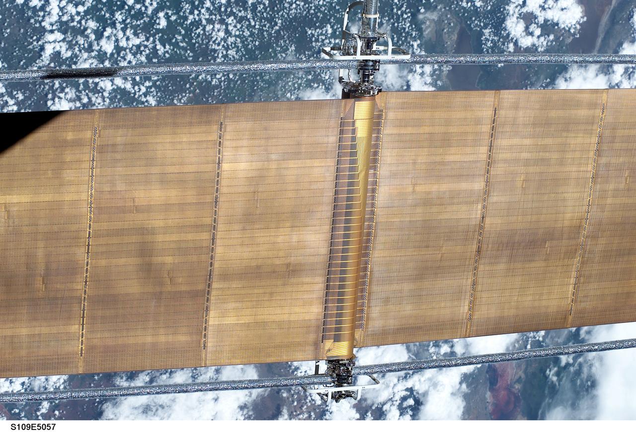
STS109-E-5057 (3 March 2002) --- One of the solar panels of the Hubble Space Telescope is pictured 350 miles above Pacific Ocean clouds Southwest of Mexico during capture operations. Astronaut Nancy J. Currie, mission specialist, was in control of the Shuttle's remote manipulator system (RMS) robotic arm and astronaut Scott D. Altman, mission commander, was at the controls of the shuttle during capture and latch activities. The crew used a digital still camera to record a series of images documenting the fourth docking of a shuttle to the giant telescope during its tenure in space.
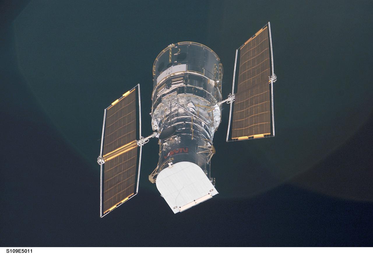
STS109-E-5011 (3 March 2002) --- The Hubble Space Telescope is backdropped against black space as the Space Shuttle Columbia, with a crew of seven astronauts on board, eases closer and closer in order to latch its 50-foot-long robotic arm onto a fixture on the giant telescope. As Columbia flew 350 miles above the Pacific Ocean Southwest of Mexico, with astronaut Nancy J. Currie, mission specialist, in control of the arm and astronaut Scott D. Altman, mission commander, at the controls of the shuttle, the crew went on to capture the Hubble. The image was one of a series recorded with a digital still camera.
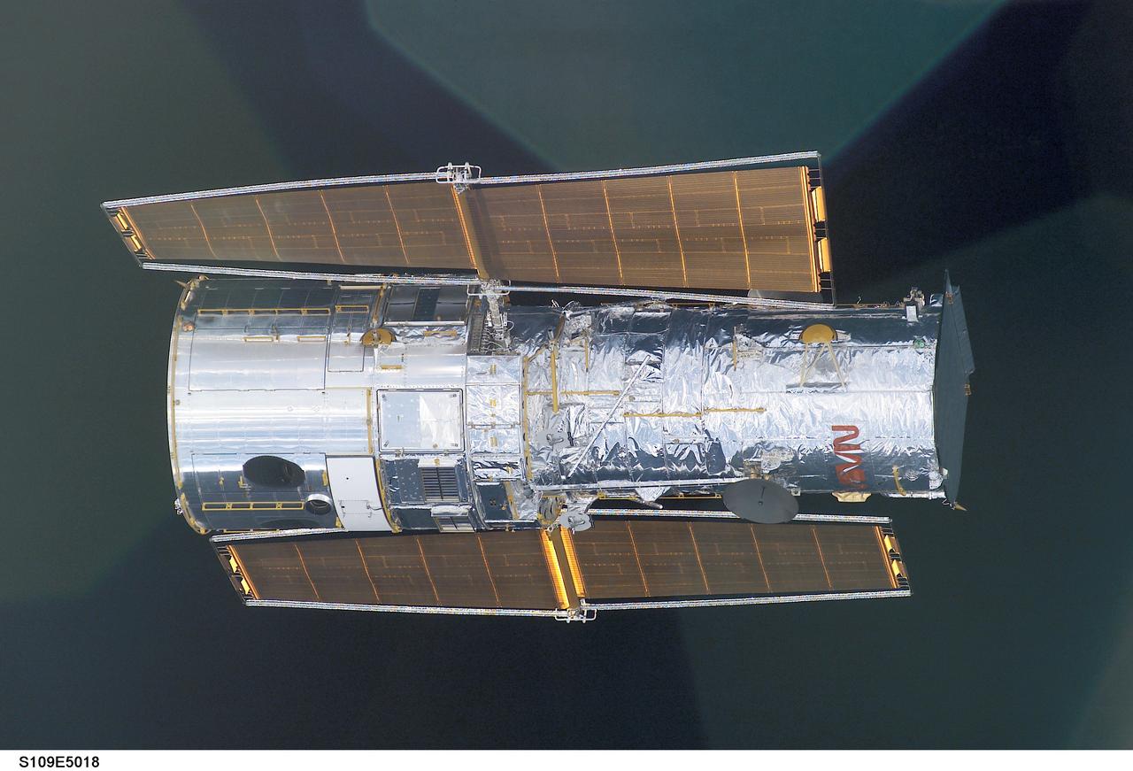
STS109-E-5018 (3 March 2002) --- The Hubble Space Telescope is backdropped against black space as the Space Shuttle Columbia, with a crew of seven stronauts on board, eases closer and closer in order to latch its 50-foot-long robotic arm onto a fixture on the giant telescope. As Columbia flew 350 miles above the Pacific Ocean Southwest of Mexico, with astronaut Nancy J. Currie, mission specialist, in control of the arm and astronaut Scott D. Altman, mission commander, at the controls of the shuttle, the crew went on to capture the Hubble. The image was one of a series recorded with a digital still camera.
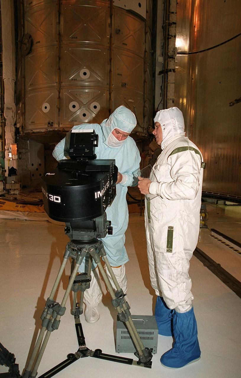
In the Payload Changeout Room at Launch Pad 39A, a film crew from IMAX prepares its 3-D movie camera to film the payload bay door closure on Atlantis. Behind them is the payload, the U.S. Laboratory Destiny, which will fly on mission STS-98, the seventh construction flight to the ISS. Destiny, a key element in the construction of the International Space Station, is 28 feet long and weighs 16 tons. This research and command-and-control center is the most sophisticated and versatile space laboratory ever built. It will ultimately house a total of 23 experiment racks for crew support and scientific research. Launch of Atlantis is Feb. 7 at 6:11 p.m. EST
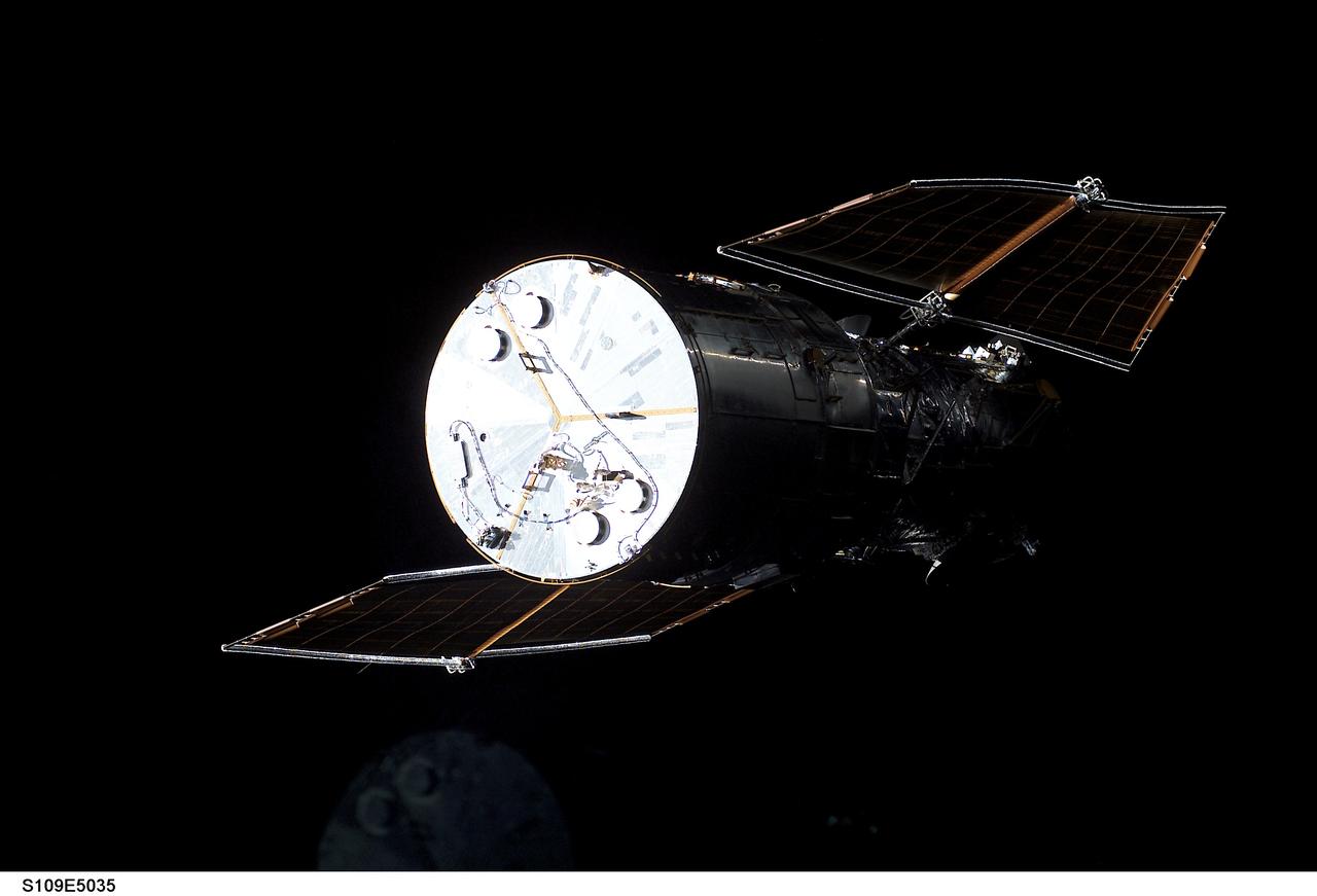
STS109-E-5035 (3 March 2002) --- The Hubble Space Telescope is visible against black space, primarily because its bright metallic disk-shaped base and the frame of its solar panels, as the Space Shuttle Columbia eases closer and closer in order to latch its 50-foot-long robotic arm onto a fixture on the giant telescope. As Columbia flew 350 miles above the Pacific Ocean Southwest of Mexico, with astronaut Nancy J. Currie, mission specialist, in control of the arm and astronaut Scott D. Altman, mission commander, at the controls of the shuttle, the seven-member crew went on to capture the Hubble. The image was one of a series recorded with a digital still camera.
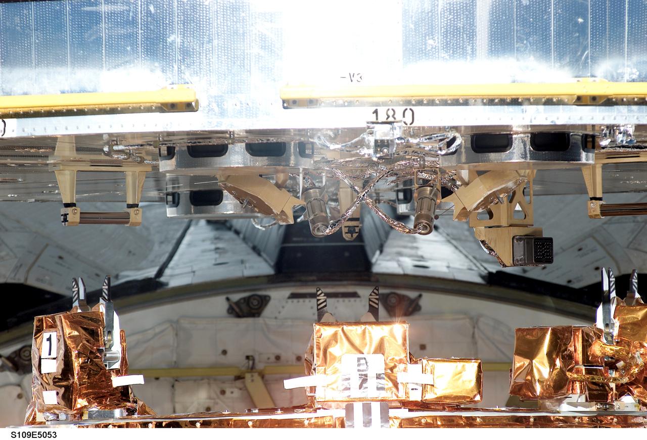
STS109-E-5053 (3 March 2002) --- The base of the Hubble Space Telescope is latched down on a special support structure in the cargo bay of the Space Shuttle Columbia. The bay's Flight Support System, as the structure (partially visible at bottom frame) is called, will hold the telescope for the next week, turning and tilting it as needed for the spacewalking work. Astronaut Nancy J. Currie, mission specialist, was in control of the Shuttle's remote manipulator system (RMS) robotic arm and astronaut Scott D. Altman, mission commander, was at the controls of the shuttle. The crew used a digital still camera to record a series of images documenting the fourth docking of a shuttle to the giant telescope during its tenure in space.
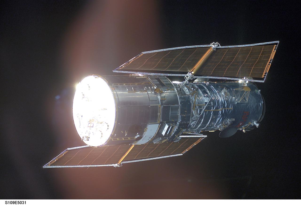
STS109-E-5031 (3 March 2002) --- The Hubble Space Telescope is backdropped against black space as the Space Shuttle Columbia, with a crew of seven astronauts on board, eases closer and closer in order to latch its 50-foot-long robotic arm onto a fixture on the giant telescope. As Columbia flew 350 miles above the Pacific Ocean Southwest of Mexico, with astronaut Nancy J. Currie, mission specialist, in control of the arm and astronaut Scott D. Altman, mission commander, at the controls of the shuttle, the crew went on to capture the Hubble. The image was one of a series recorded with a digital still camera.
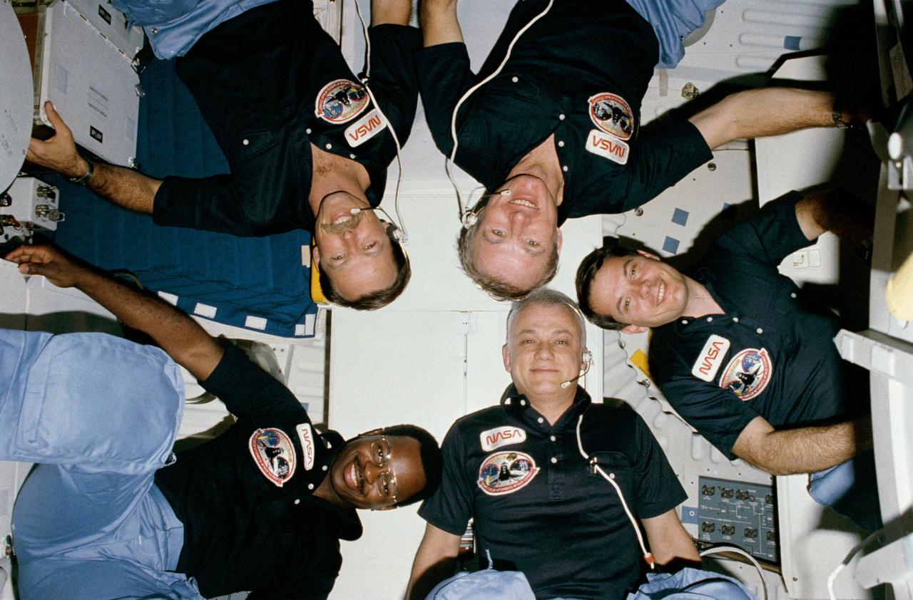
S84-27026 (3-11 Feb. 1984) --- The "star burst" type informal portrait of Space Shuttle crews has become somewhat of a tradition and the five-member STS-41B crew is no exception. HOLD PICTURE WITH SEMI-CIRCLE AT LOWER RIGHT CORNER. Counter clockwise from the lower left are Astronauts Vance D. Brand commander; Robert L. Gibson, pilot; and Dr. Ronald E. McNair; Bruce McCandless II and Robert L. Stewart, all mission specialists. The five are on the mid-deck of the Earth-orbiting Challenger. The "semi-circle" is actually part of the monodisperse latex reactor (MLR) experiment. A pre-set 35mm camera was triggered automatically to expose the frame.
STS109-E-5014 (3 March 2002) --- The Hubble Space Telescope is backdropped against black space as the Space Shuttle Columbia, with a crew of seven astronauts on board, eases closer and closer in order to latch its 50-foot-long robotic arm onto a fixture on the giant telescope. As Columbia flew 350 miles above the Pacific Ocean Southwest of Mexico, with astronaut Nancy J. Currie, mission specialist, in control of the arm and astronaut Scott D. Altman, mission commander, at the controls of the shuttle, the crew went on to capture the Hubble. The image was one of a series recorded with a digital still camera.
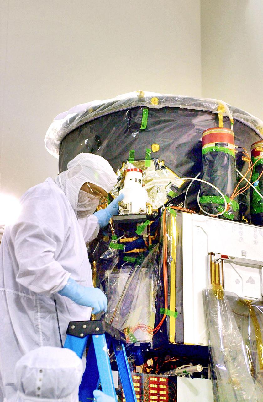
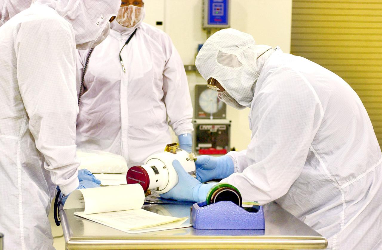
KENNEDY SPACE CENTER, FLA. - Inside the Astrotech Payload Processing Facility on Vandenberg Air Force Base in California, a worker installs the Wide Field Camera on the Cloud-Aerosol Lidar and Infrared Pathfinder Satellite Observation (CALIPSO) spacecraft. CALIPSO will fly in combination with the CloudSat satellite to provide never-before-seen 3-D perspectives of how clouds and aerosols form, evolve, and affect weather and climate. CALIPSO and CloudSat will join three other satellites in orbit to enhance understanding of climate systems. The launch date for CALIPSO_CloudSat is no earlier than Aug. 22.
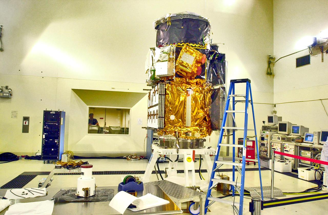
KENNEDY SPACE CENTER, FLA. - Inside the Astrotech Payload Processing Facility on Vandenberg Air Force Base in California, the Cloud-Aerosol Lidar and Infrared Pathfinder Satellite Observation (CALIPSO) spacecraft waits on a workstand for installation of a Wide Field Camera, on the floor at left. CALIPSO will fly in combination with the CloudSat satellite to provide never-before-seen 3-D perspectives of how clouds and aerosols form, evolve, and affect weather and climate. CALIPSO and CloudSat will join three other satellites in orbit to enhance understanding of climate systems. The launch date for CALIPSO_CloudSat is no earlier than Aug. 22.
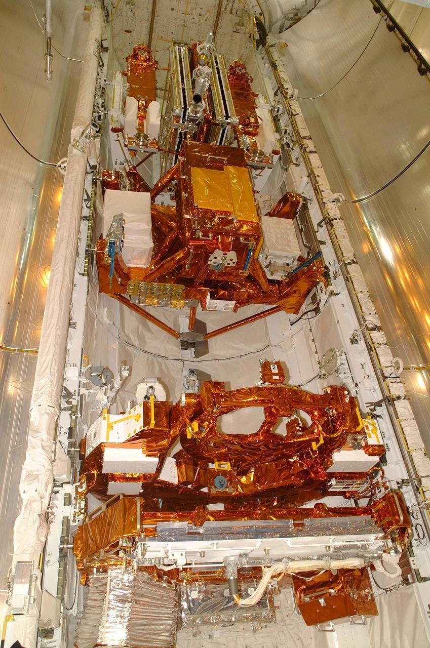
KENNEDY SPACE CENTER, FLA. -- All of the payload elements on mission STS-109 are installed in Columbia's payload bay: Solar Array 3, a new Power Control Unit, the Advanced Camera for Surveys (ACS), Near Infrared Camera, Multi-Object Spectrometer (NICMOS) Cooling System, and New Outer Blanket Layer insulation. Four mission specialists will perform five scheduled spacewalks to complete system upgrades to the telescope with these components. The STS-109 crew includes Commander Scott D. Altman, Pilot Duane G. Carey, and Mission Specialists John M. Grunsfeld, Nancy J. Currie, James H. Newman, Richard M. Linnehan and Michael J. Massimino. Launch is scheduled for Feb. 28, 2002, at 6:48 a.m. EST (11:48 GMT). Photo by Carl Winebarger
STS063-S-003 (3 Feb. 1995) --- A 35mm camera was used to expose this image of the space shuttle Discovery as it began its race to catch up with the Russia's Mir Space Station. Liftoff from Launch Pad 39B, Kennedy Space Center (KSC) occurred at 12:22:04 (EST), Feb. 3, 1995. Discovery is the first in the current fleet of four space shuttle vehicles to make 20 launches. Onboard for the 67th (STS-63 is out of sequence) shuttle flight are astronauts James D. Wetherbee, commander; Eileen M. Collins, pilot; Bernard A. Harris Jr., payload commander; and mission specialists Janice Voss and C. Michael Foale; along with Russian cosmonaut Vladimir G. Titov. Photo credit: NASA
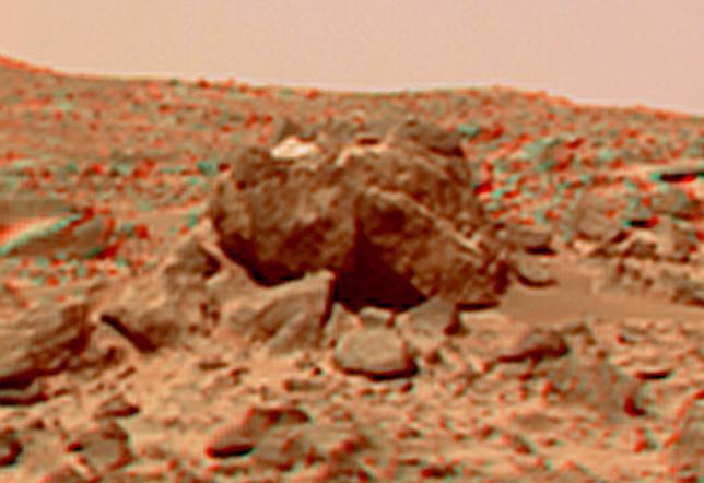
This view of the "Hippo," 25 meters to the west of the lander, was produced by combining the "Super Panorama" frames from the IMP camera. Super resolution was applied to help to address questions about the texture of this rock and what it might tell us about its mode of origin. The composite color frames that make up this anaglyph were produced for both the right and left eye of the IMP. These composites consist of more than 15 frames per eye (because multiple sequences covered the same area), taken with different color filters that were enlarged by 500% and then co-added using Adobe Photoshop to produce, in effect, a super-resolution panchromatic frame that is sharper than an individual frame would be. These panchromatic frames were then colorized with the red, green, and blue filtered images from the same sequence. The color balance was adjusted to approximate the true color of Mars. The anaglyph view was produced by combining the left with the right eye color composite frames by assigning the left eye composite view to the red color plane and the right eye composite view to the green and blue color planes (cyan), to produce a stereo anaglyph mosaic. This mosaic can be viewed in 3-D on your computer monitor or in color print form by wearing red-blue 3-D glasses. http://photojournal.jpl.nasa.gov/catalog/PIA01421
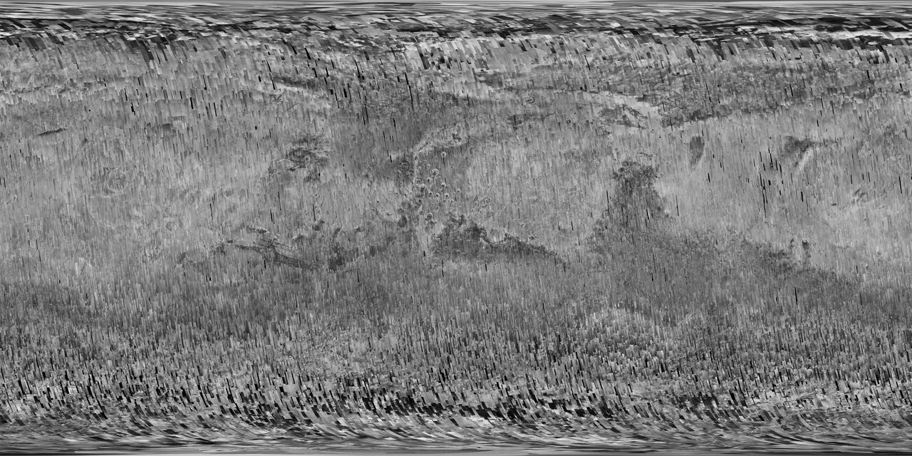
In early 2017, after more than a decade of observing Mars, the Context Camera (CTX) on NASA's Mars Reconnaissance Orbiter (MRO) surpassed 99 percent coverage of the entire planet. This mosaic shows that global coverage. No other camera has ever imaged so much of Mars in such high resolution. The mosaic offers a resolution that enables zooming in for more detail of any region of Mars. It is still far from the full resolution of individual CTX observations, which can reveal the shapes of features smaller than the size of a tennis court. As of March 2017, the Context Camera has taken about 90,000 images since the spacecraft began examining Mars from orbit in late 2006. In addition to covering 99.1 percent of the surface of Mars at least once, this camera has observed more than 60 percent of Mars more than once, checking for changes over time and providing stereo pairs for 3-D modeling of the surface. http://photojournal.jpl.nasa.gov/catalog/PIA21488
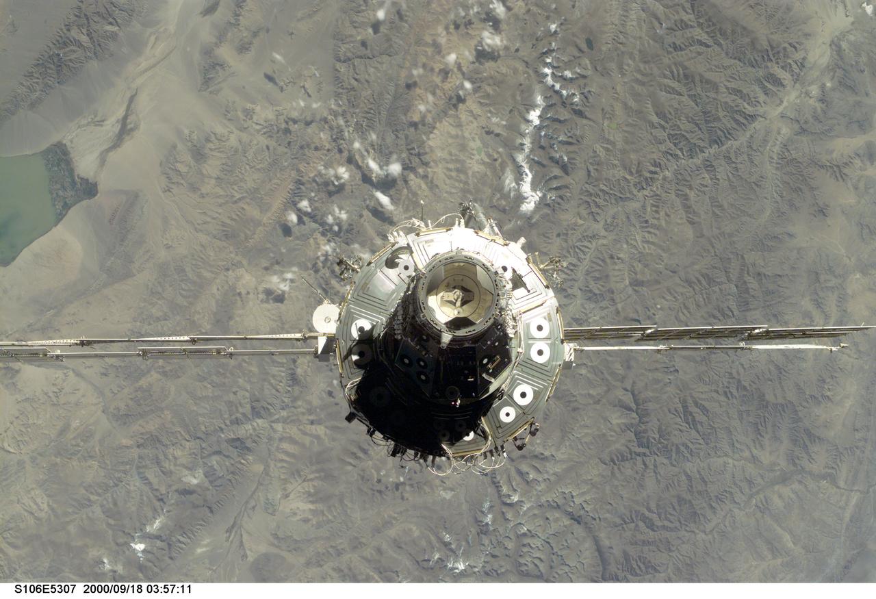
S106-E-5307 (18 September 2000) --- The International Space Station (ISS), with its U.S.-built Unity node facing the camera, is seen following its undocking with the Space Shuttle Atlantis. After accomplishing all mission objectives in outfitting the station for the first resident crew, the seven astronauts and cosmonauts undocked at 3:46 (GMT) on Sept. 18 over Russia near the northeastern portion of Ukraine. When Atlantis was at a safe distance from the station, about 450 feet, astronaut Scott D. Altman, pilot, performed a 90-minute, double-loop fly around to enable the crew to document the station’s exterior. He fired Atlantis’ jets one final time to separate from the station at 5:35 GMT, September 18.
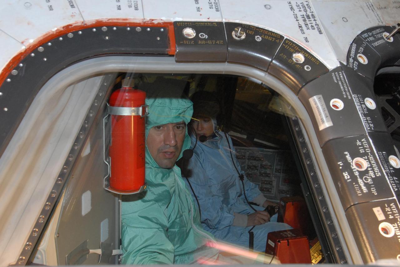
KENNEDY SPACE CENTER, FLA. - In the Orbiter Processing Facility bay 3, STS-120 Pilot George D. Zamka makes a close inspection of the cockpit window on the orbiter Discovery. Seated next to him is Commander Pamela A. Melroy. The STS-120 crew is at Kennedy for a crew equipment interface test, or CEIT, which includes harness training, inspection of the thermal protection system and camera operation for planned extravehicular activities, or EVAs. The STS-120 mission will deliver the Harmony module, christened after a school contest, which will provide attachment points for European and Japanese laboratory modules on the International Space Station. Known in technical circles as Node 2, it is similar to the six-sided Unity module that links the U.S. and Russian sections of the station. Built in Italy for the United States, Harmony will be the first new U.S. pressurized component to be added. The STS-120 mission is targeted to launch on Oct. 20. Photo credit: NASA/George Shelton
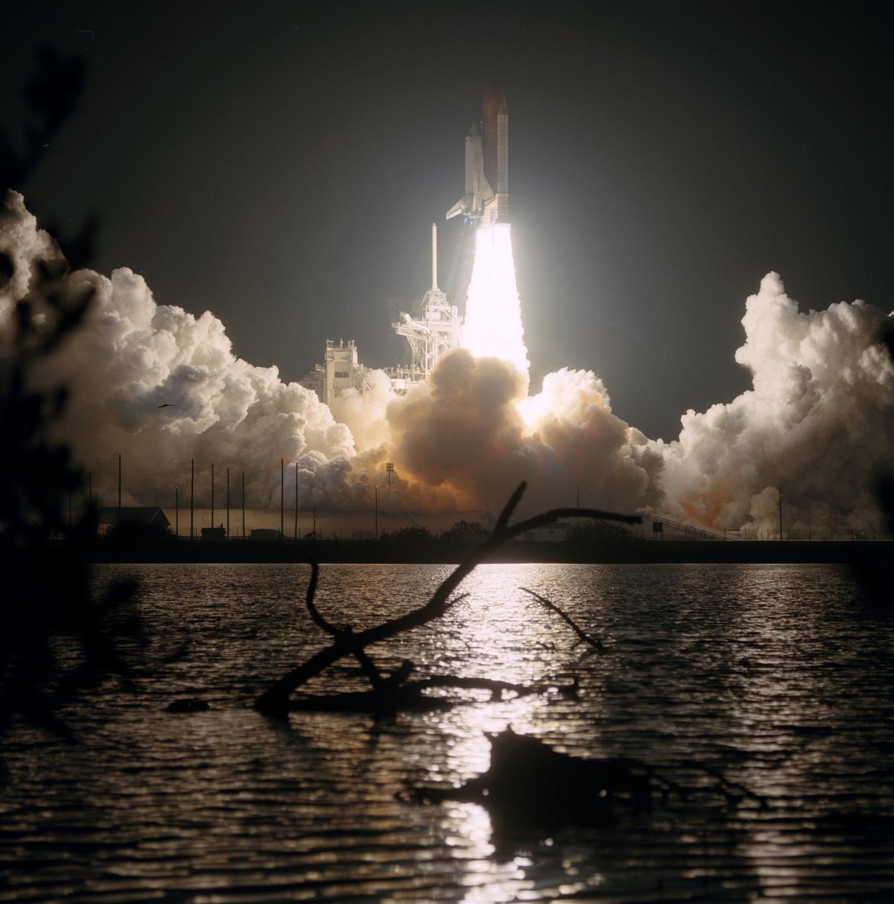
STS082-S-006 (11 Feb 1997) --- A remote camera provides this distant shot of the Space Shuttle Discovery as it lights up the early morning sky around Launch Pad 39A, at the Kennedy Space Center (KSC). Discovery?s flight is a scheduled 10-day mission in Earth-orbit to service the Hubble Space Telescope (HST). Launch occurred at 3:55:17 a.m. (EST), February 11, 1997. The crew members are astronauts Kenneth D. Bowersox, commander; Scott J. Horowitz, pilot; Mark C. Lee, payload commander; and mission specialists Steven A. Hawley, Gregory J. Harbaugh, Steven L. Smith and Joseph R. Tanner. STS-82 represents the 22nd flight of Discovery and the 82nd Space Transportation System (STS) flight.
KENNEDY SPACE CENTER, FLA. - The STS-120 crew is at Kennedy for a crew equipment interface test, or CEIT. Giving a close inspection to space shuttle Discovery in Orbiter Processing Facility bay 3 are Mission Specialist Stephanie D. Wilson and Commander Pamela A. Melroy. Among the activities standard to a CEIT are harness training, inspection of the thermal protection system and camera operation for planned extravehicular activities, or EVAs. The STS-120 mission will deliver the Harmony module, christened after a school contest, which will provide attachment points for European and Japanese laboratory modules on the International Space Station. Known in technical circles as Node 2, it is similar to the six-sided Unity module that links the U.S. and Russian sections of the station. Built in Italy for the United States, Harmony will be the first new U.S. pressurized component to be added. The STS-120 mission is targeted to launch on Oct. 20. Photo credit: NASA/George Shelton
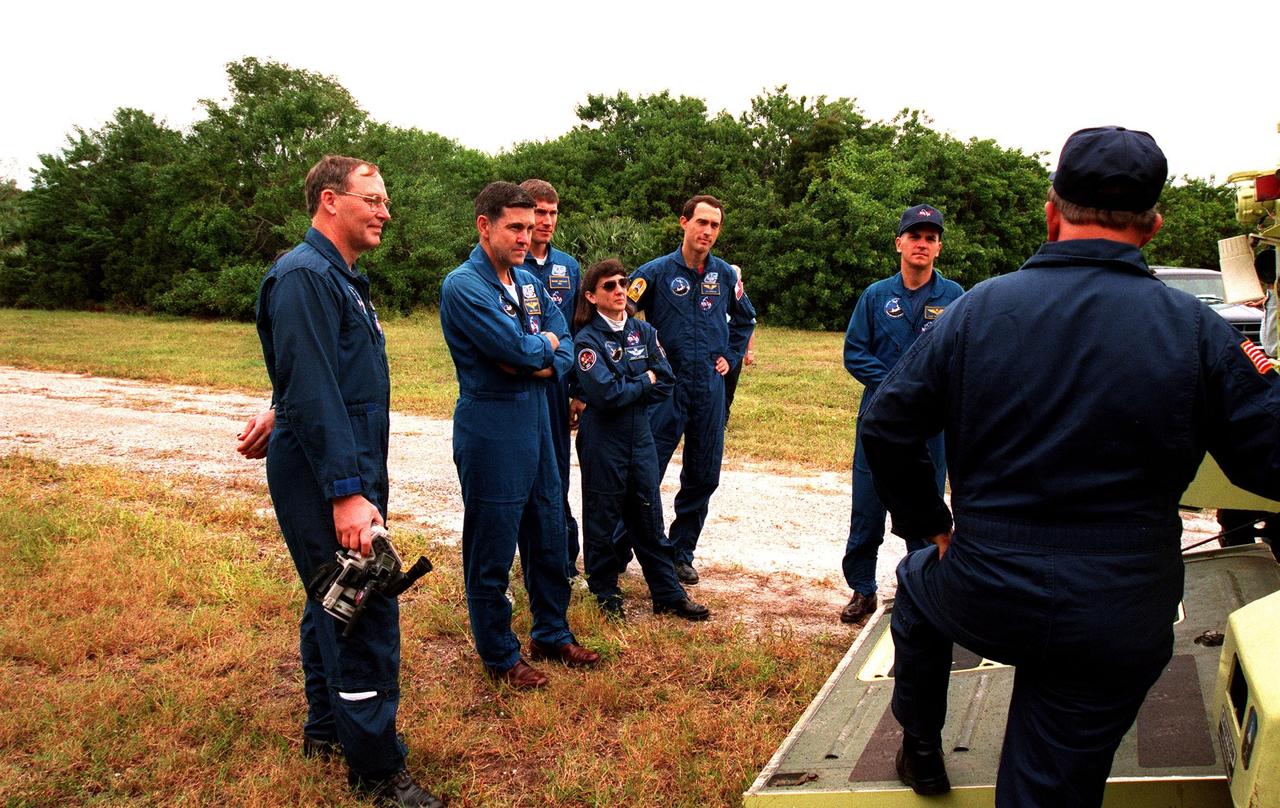
The STS-88 crew receives instruction on the operation of an M-113, an armored personnel carrier, as part of emergency egress training from George Hoggard (back to camera) during Terminal Countdown Demonstration Test (TCDT) activities. From left to right, they are Mission Specialist Jerry L. Ross; Mission Commander Robert D. Cabana; Mission Specialist Sergei Konstantinovich Krikalev, a Russian cosmonaut; Mission Specialist Nancy J. Currie; Mission Specialist James H. Newman; and Pilot Frederick W. "Rick" Sturckow. The TCDT also provides the crew with simulated countdown exercises and opportunities to inspect their mission payloads in the orbiter's payload bay. Mission STS-88 is targeted for launch on Dec. 3, 1998. It is the first U.S. flight for the assembly of the International Space Station and will carry the Unity connecting module
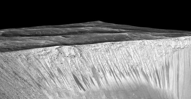
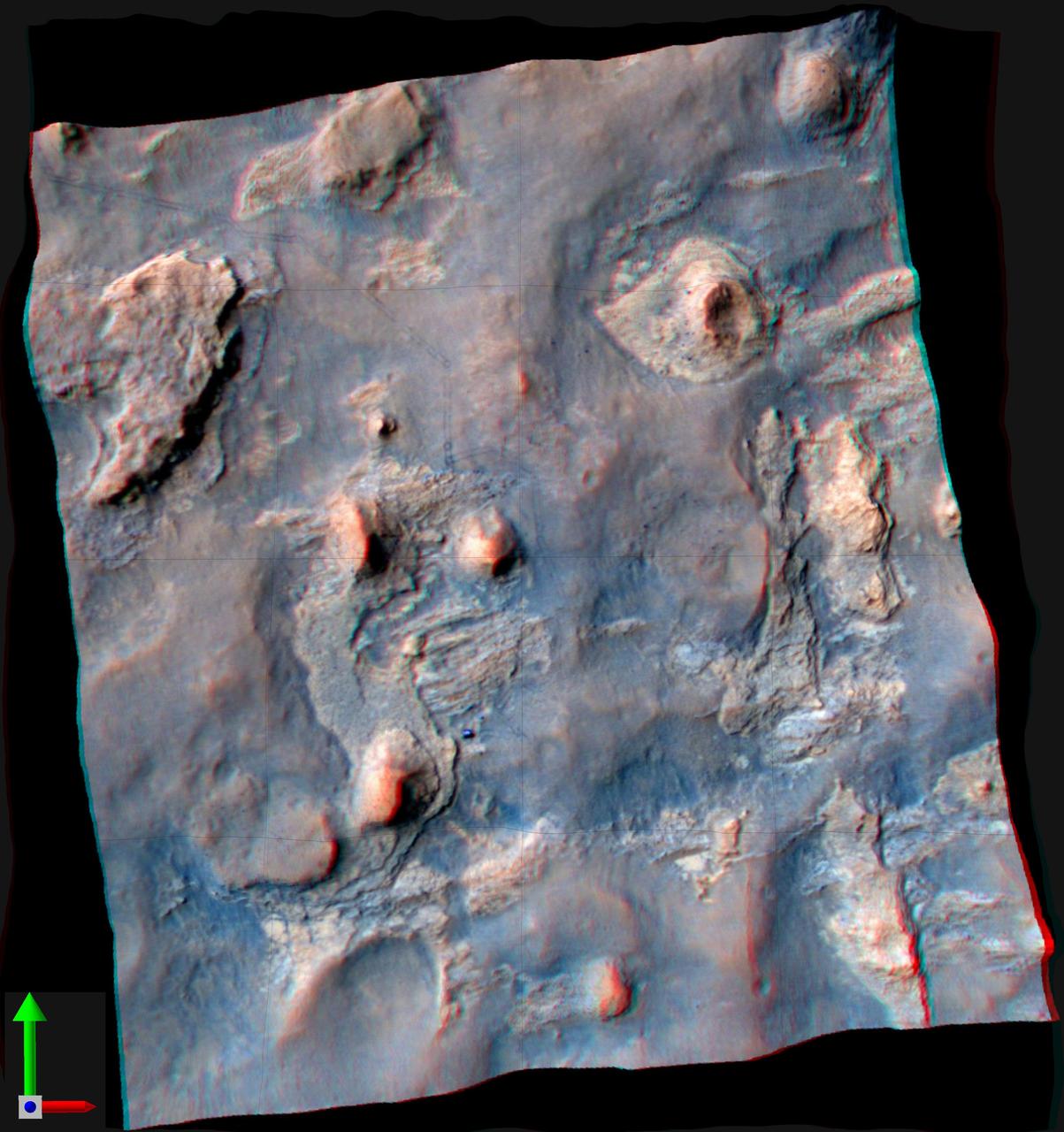
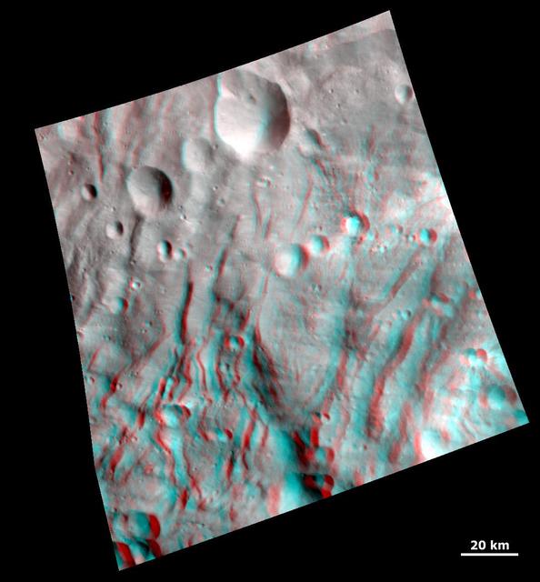
Dark narrow streaks, called "recurring slope lineae," emanate from the walls of Garni Crater on Mars, in this view constructed from observations by the High Resolution Imaging Science Experiment (HiRISE) camera on NASA's Mars Reconnaissance Orbiter. The dark streaks here are up to few hundred yards, or meters, long. They are hypothesized to be formed by flow of briny liquid water on Mars. The image was produced by first creating a 3-D computer model (a digital terrain map) of the area based on stereo information from two HiRISE observations, and then draping an image over the land-shape model. The vertical dimension is exaggerated by a factor of 1.5 compared to horizontal dimensions. The draped image is a red waveband (monochrome) product from HiRISE observation ESP_031059_1685, taken on March 12, 2013 at 11.5 degrees south latitude, 290.3 degrees east longitude. Other image products from this observation are at http://hirise.lpl.arizona.edu/ESP_031059_1685. http://photojournal.jpl.nasa.gov/catalog/PIA19917
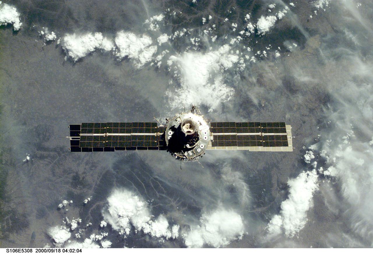
S106-E-5308 (18 September 2000) --- The International Space Station (ISS), with its U.S.-built Unity node facing the camera, is seen following its undocking with the Space Shuttle Atlantis. After accomplishing all mission objectives in outfitting the station for the first resident crew, the seven astronauts and cosmonauts undocked at 3:46 (GMT) on Sept. 18 over Russia near the northeastern portion of Ukraine. When Atlantis was at a safe distance from the station, about 450 feet, astronaut Scott D. Altman, pilot, performed a 90-minute, double-loop fly around to enable the crew to document the station’s exterior. He fired Atlantis’ jets one final time to separate from the station at 5:35 GMT, September 18.
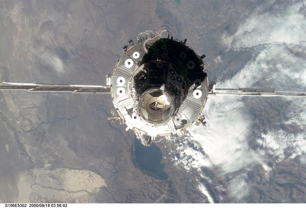
S106-E-5302 (18 September 2000) --- The International Space Station (ISS) is seen with the U.S.-built Unity node facing the camera, following its undocking with the Space Shuttle Atlantis. After accomplishing all mission objectives in outfitting the station for the first resident crew, the seven astronauts and cosmonauts undocked at 3:46 (GMT) on Sept. 18 over Russia near the northeastern portion of Ukraine. When Atlantis was at a safe distance from the station, about 450 feet, astronaut Scott D. Altman, pilot, performed a 90-minute, double-loop fly around to enable the crew to document the station’s exterior. He fired Atlantis’ jets one final time to separate from the station at 5:35 GMT, September 18.
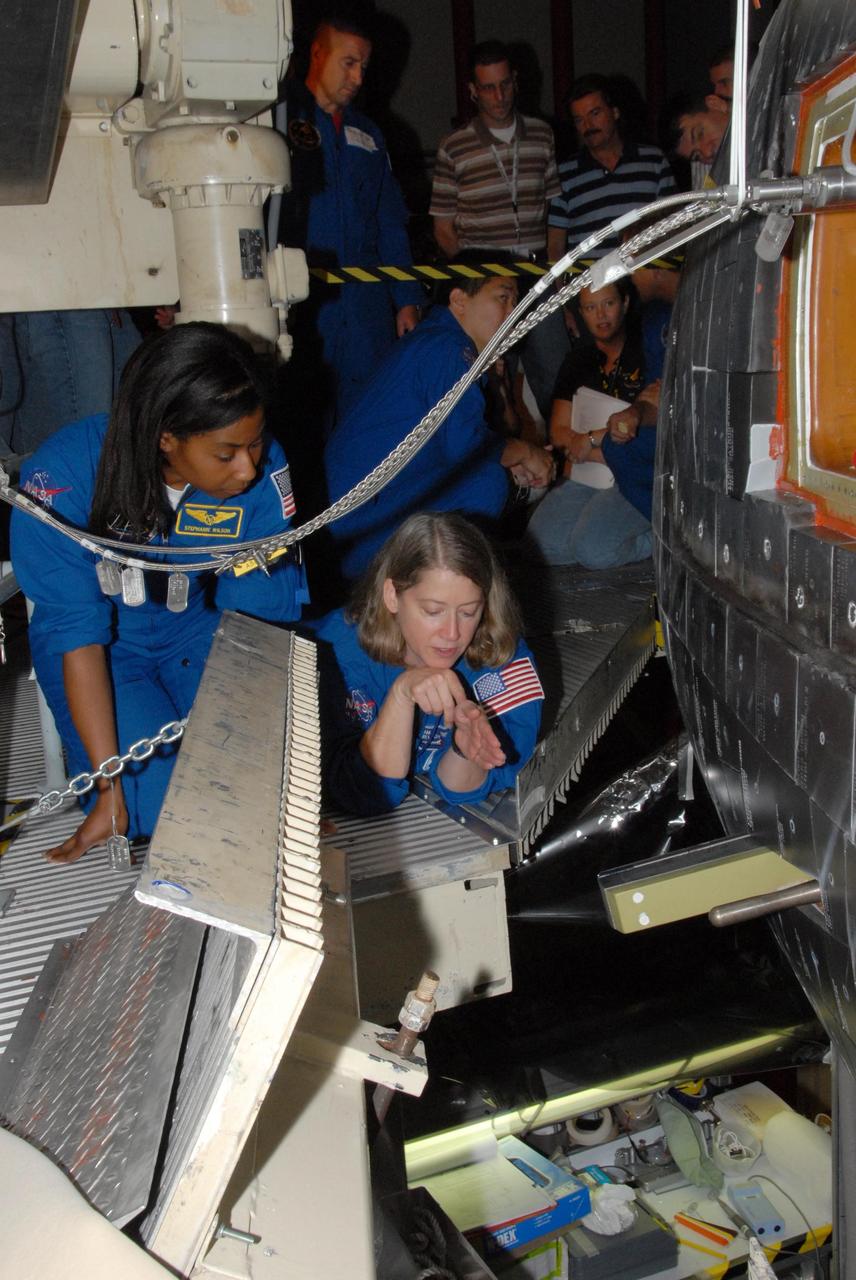
KENNEDY SPACE CENTER, FLA. -In Orbiter Processing Facility bay 3, STS-120 Commander Pamela A. Melroy (center left) and Mission Specialist Stephanie D. Wilson (center right) are lowered in a bucket into Discovery's payload bay. The STS-120 crew is at Kennedy for a crew equipment interface test, or CEIT, which includes harness training, inspection of the thermal protection system and camera operation for planned extravehicular activities, or EVAs. The STS-120 mission will deliver the Harmony module, christened after a school contest, which will provide attachment points for European and Japanese laboratory modules on the International Space Station. Known in technical circles as Node 2, it is similar to the six-sided Unity module that links the U.S. and Russian sections of the station. Built in Italy for the United States, Harmony will be the first new U.S. pressurized component to be added. The STS-120 mission is targeted to launch on Oct. 20. Photo credit: NASA/George Shelton
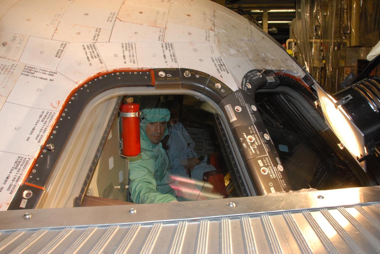
KENNEDY SPACE CENTER, FLA. - In the Orbiter Processing Facility bay 3, STS-120 Pilot George D. Zamka makes a close inspection of the cockpit window on the orbiter Discovery. Seated next to him is Commander Pamela A. Melroy. The STS-120 crew is at Kennedy for a crew equipment interface test, or CEIT, which includes harness training, inspection of the thermal protection system and camera operation for planned extravehicular activities, or EVAs. The STS-120 mission will deliver the Harmony module, christened after a school contest, which will provide attachment points for European and Japanese laboratory modules on the International Space Station. Known in technical circles as Node 2, it is similar to the six-sided Unity module that links the U.S. and Russian sections of the station. Built in Italy for the United States, Harmony will be the first new U.S. pressurized component to be added. The STS-120 mission is targeted to launch on Oct. 20. NASA/George Shelton
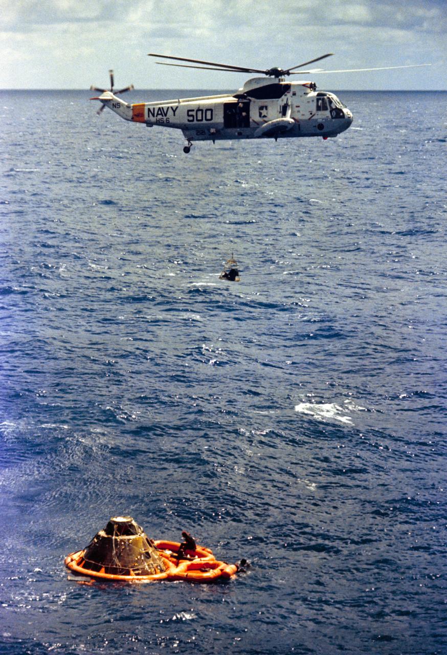
S71-19476 (9 Feb. 1971) --- Astronaut Stuart A. Roosa, command module pilot, is hoisted inside a Billy Pugh net to a U.S. Navy helicopter assisting in Apollo 14 recovery operations in the South Pacific Ocean. Visible in a life raft beside the Command Module (CM) are astronauts Alan B. Shepard Jr., commander, back to camera; and Edgar D. Mitchell (partially obscured by the spacecraft), lunar module pilot. Three U.S. Navy underwater demolition team swimmers who assisted in the recovery operations are pictured in and around the life raft. Apollo 14 splashdown occurred at 3:04:39 p.m. (CST), Feb. 9, 1971, approximately 765 nautical miles south of American Samoa in the South Pacific Ocean.
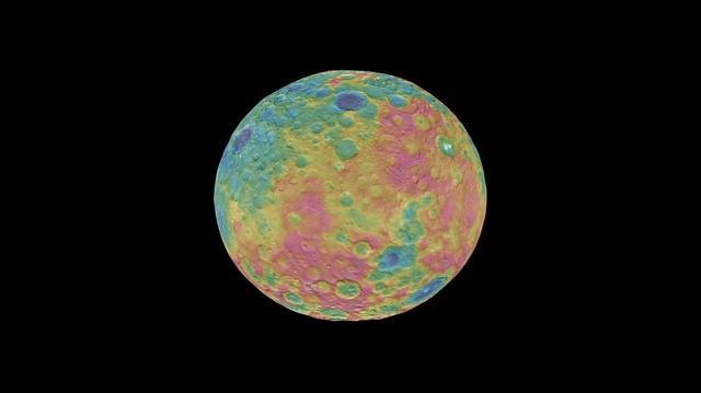
This frame from an animation shows a color-coded map from NASA Dawn mission revealing the highs and lows of topography on the surface of dwarf planet Ceres. The color scale extends 3.7 miles (6 kilometers) below the surface in purple to 3.7 miles (6 kilometers) above the surface in brown. The brightest features (those appearing nearly white) -- including the well-known bright spots within a crater in the northern hemisphere -- are simply reflective areas, and do not represent elevation. The topographic map was constructed from analyzing images from Dawn's framing camera taken from varying sun and viewing angles. The map was combined with an image mosaic of Ceres and projected onto a 3-D shape model of the dwarf planet to create the animation. http://photojournal.jpl.nasa.gov/catalog/PIA19605

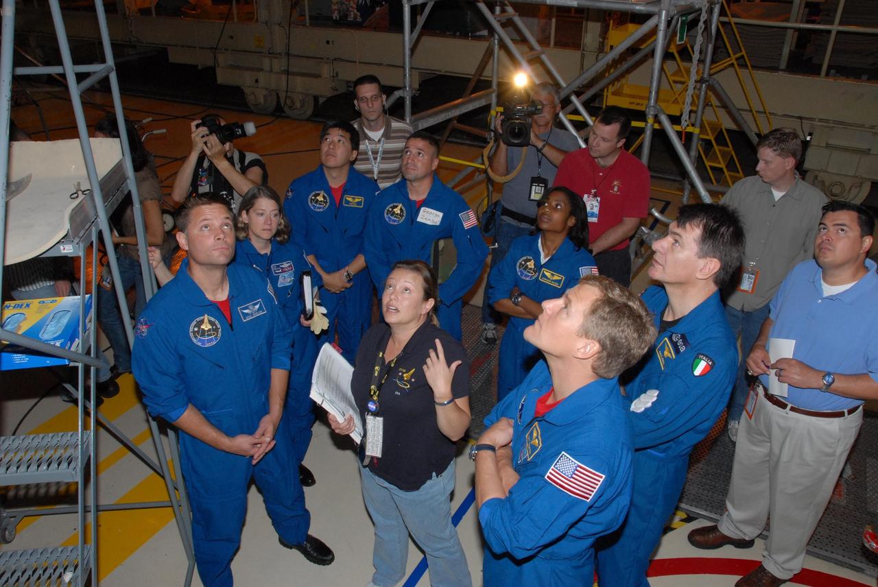
KENNEDY SPACE CENTER, FLA. - The STS-120 crew is at Kennedy for a crew equipment interface test, or CEIT. Inspecting the thermal protection system, or TPS, tiles under space shuttle Discovery in Orbiter Processing Facility bay 3 are, from left, Mission Specialist Douglas H. Wheelock (standing); Pilot George D. Zamka; Mission Specialist Paolo A. Nespoli, a European Space Agency astronaut from Italy; Allison Bolinger (pointing), an EVA technician with NASA; Commander Pamela A. Melroy; Mission Specialists Scott E. Parazynski and Stephanie D. Wilson; two support personnel and Erin Schlichenmaier, with United Space Alliance TPS Engineering. Among the activities standard to a CEIT are harness training, inspection of the thermal protection system and camera operation for planned extravehicular activities, or EVAs. The STS-120 mission will deliver the Harmony module, christened after a school contest, which will provide attachment points for European and Japanese laboratory modules on the International Space Station. Known in technical circles as Node 2, it is similar to the six-sided Unity module that links the U.S. and Russian sections of the station. Built in Italy for the United States, Harmony will be the first new U.S. pressurized component to be added. The STS-120 mission is targeted to launch on Oct. 20. Photo credit: NASA/George Shelton
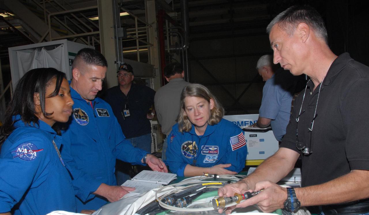
KENNEDY SPACE CENTER, FLA. - In Orbiter Processing Facility bay 3, STS-120 crew members practice handling tools they will use during the mission. From left are Mission Specialist Stephanie D. Wilson, Pilot George D. Zamka and Commander Pamela A. Melroy. The STS-120 crew is at Kennedy for a crew equipment interface test, or CEIT, which includes harness training, inspection of the thermal protection system and camera operation for planned extravehicular activities, or EVAs. The STS-120 mission will deliver the Harmony module, christened after a school contest, which will provide attachment points for European and Japanese laboratory modules on the International Space Station. Known in technical circles as Node 2, it is similar to the six-sided Unity module that links the U.S. and Russian sections of the station. Built in Italy for the United States, Harmony will be the first new U.S. pressurized component to be added. The STS-120 mission is targeted to launch on Oct. 20. Photo credit: NASA/George Shelton
KENNEDY SPACE CENTER, FLA. - The STS-120 crew is at Kennedy for a crew equipment interface test, or CEIT. Inspecting the thermal protection system, or TPS, tiles under space shuttle Discovery in Orbiter Processing Facility bay 3 are, from left, Expedition 16 Flight Engineer Daniel M. Tani; Mission Specialist Douglas H. Wheelock; Pilot George D. Zamka; Mission Specialist Paolo A. Nespoli, a European Space Agency astronaut from Italy; Allison Bolinger, an EVA technician with NASA; Mission Specialists Scott E. Parazynski and Stephanie D. Wilson; and Erin Schlichenmaier, of TPS Engineering with United Space Alliance. Among the activities standard to a CEIT are harness training, inspection of the thermal protection system and camera operation for planned extravehicular activities, or EVAs. The STS-120 mission will deliver the Harmony module, christened after a school contest, which will provide attachment points for European and Japanese laboratory modules on the International Space Station. Known in technical circles as Node 2, it is similar to the six-sided Unity module that links the U.S. and Russian sections of the station. Built in Italy for the United States, Harmony will be the first new U.S. pressurized component to be added. The STS-120 mission is targeted to launch on Oct. 20. Photo credit: NASA/George Shelton
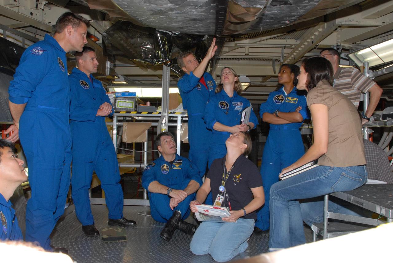
KENNEDY SPACE CENTER, FLA. - The STS-120 crew is at Kennedy for a crew equipment interface test, or CEIT. Inspecting the thermal protection system, or TPS, tiles under space shuttle Discovery in Orbiter Processing Facility bay 3 are, from left, Expedition 16 Flight Engineer Daniel M. Tani; Mission Specialist Douglas H. Wheelock; Pilot George D. Zamka; Mission Specialist Paolo A. Nespoli (kneeling), a European Space Agency astronaut from Italy; Mission Specialist Scott E. Parazynski; Commander Pamela A. Melroy; Allison Bolinger (kneeling), an EVA technician with NASA; Mission Specialist Stephanie D. Wilson; and Erin Schlichenmaier, with United Space Alliance TPS Engineering. Among the activities standard to a CEIT are harness training, inspection of the thermal protection system and camera operation for planned extravehicular activities, or EVAs. The STS-120 mission will deliver the Harmony module, christened after a school contest, which will provide attachment points for European and Japanese laboratory modules on the International Space Station. Known in technical circles as Node 2, it is similar to the six-sided Unity module that links the U.S. and Russian sections of the station. Built in Italy for the United States, Harmony will be the first new U.S. pressurized component to be added. The STS-120 mission is targeted to launch on Oct. 20. Photo credit: NASA/George Shelton
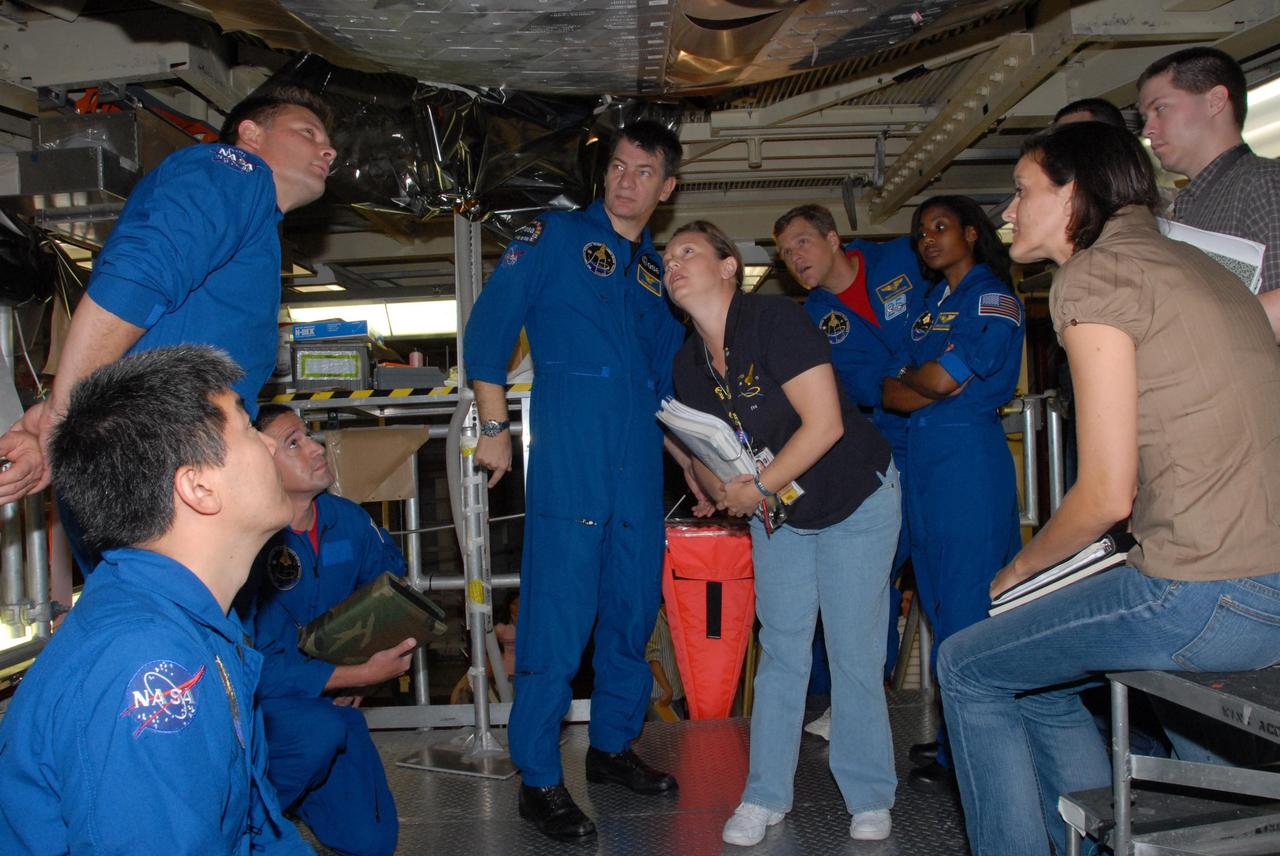
KENNEDY SPACE CENTER, FLA. - The STS-120 crew is at Kennedy for a crew equipment interface test, or CEIT. Receiving instruction from Allison Bolinger, an EVA technician with NASA, under space shuttle Discovery in Orbiter Processing Facility bay 3 are, from left in blue flight suits, Mission Specialist Douglas H. Wheelock; Commander Pamela A. Melroy; Expedition 16 Flight Engineer Daniel M. Tani; Pilot George D. Zamka; and Mission Specialists Stephanie D. Wilson, Scott E. Parazynski and Paolo A. Nespoli, a European Space Agency astronaut from Italy. Among the activities standard to a CEIT are harness training, inspection of the thermal protection system and camera operation for planned extravehicular activities, or EVAs. The STS-120 mission will deliver the Harmony module, christened after a school contest, which will provide attachment points for European and Japanese laboratory modules on the International Space Station. Known in technical circles as Node 2, it is similar to the six-sided Unity module that links the U.S. and Russian sections of the station. Built in Italy for the United States, Harmony will be the first new U.S. pressurized component to be added. The STS-120 mission is targeted to launch on Oct. 20. Photo credit: NASA/George Shelton
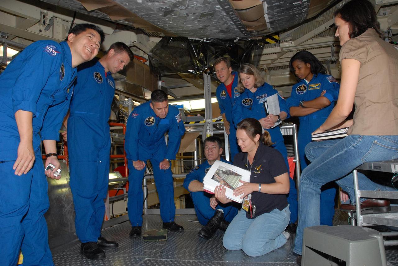
KENNEDY SPACE CENTER, FLA. - The STS-120 crew is at Kennedy for a crew equipment interface test, or CEIT. Inspecting the thermal protection system, or TPS, tiles under space shuttle Discovery in Orbiter Processing Facility bay 3 are, from left, Expedition 16 Flight Engineer Daniel M. Tani; Mission Specialist Douglas H. Wheelock; Pilot George D. Zamka; Mission Specialist Paolo A. Nespoli (sitting), a European Space Agency astronaut from Italy; Mission Specialist Scott E. Parazynski (pointing); Commander Pamela A. Melroy; Allison Bolinger (kneeling), an EVA technician with NASA; Mission Specialist Stephanie D. Wilson; and Erin Schlichenmaier, with United Space Alliance TPS Engineering. Among the activities standard to a CEIT are harness training, inspection of the thermal protection system and camera operation for planned extravehicular activities, or EVAs. The STS-120 mission will deliver the Harmony module, christened after a school contest, which will provide attachment points for European and Japanese laboratory modules on the International Space Station. Known in technical circles as Node 2, it is similar to the six-sided Unity module that links the U.S. and Russian sections of the station. Built in Italy for the United States, Harmony will be the first new U.S. pressurized component to be added. The STS-120 mission is targeted to launch on Oct. 20. Photo credit: NASA/George Shelton
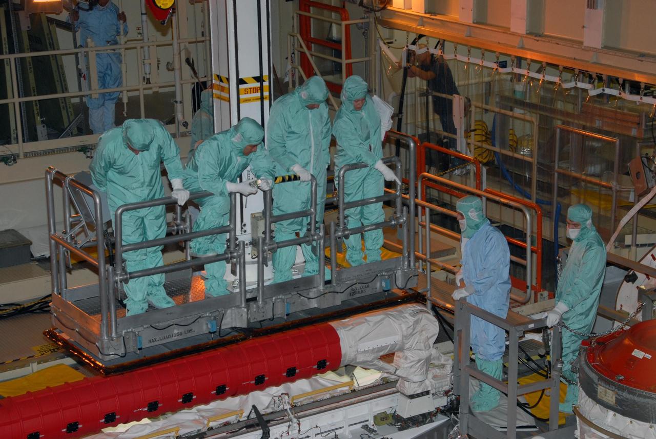
KENNEDY SPACE CENTER, FLA. - In Orbiter Processing Facility bay 3, STS-120 crew members get a close look at hardware in Discovery's payload bay. The crew includes Commander Pamela A. Melroy, Pilot George D. Zamka and Mission Specialists Scott E. Parazynski, Douglas H. Wheelock, Stephanie D. Wilson and Paolo A. Nespoli, who is a European Space Agency astronaut from Italy. The STS-120 crew is at Kennedy for a crew equipment interface test, or CEIT, which includes harness training, inspection of the thermal protection system and camera operation for planned extravehicular activities, or EVAs. The STS-120 mission will deliver the Harmony module, christened after a school contest, which will provide attachment points for European and Japanese laboratory modules on the International Space Station. Known in technical circles as Node 2, it is similar to the six-sided Unity module that links the U.S. and Russian sections of the station. Built in Italy for the United States, Harmony will be the first new U.S. pressurized component to be added. The STS-120 mission is targeted to launch on Oct. 20. Photo credit: NASA/George Shelton