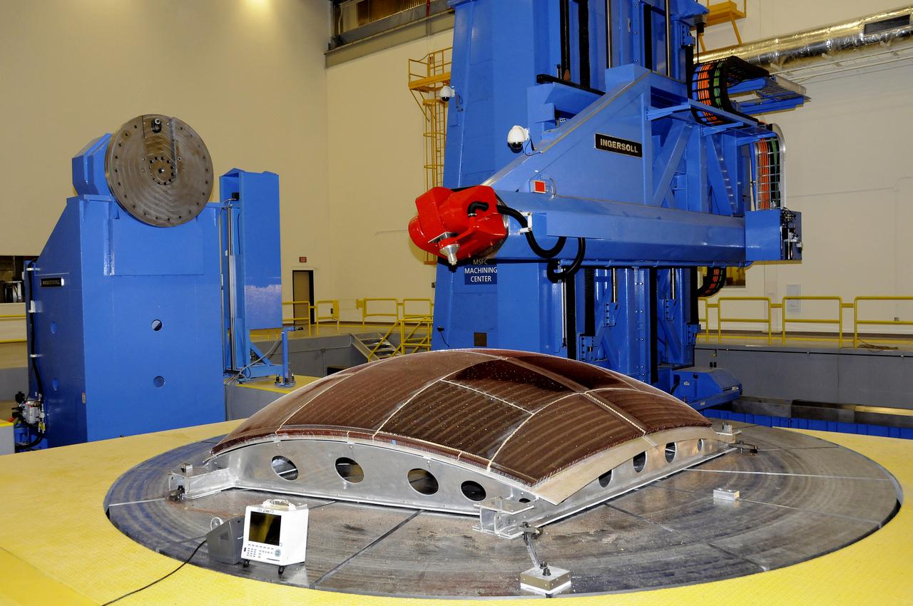
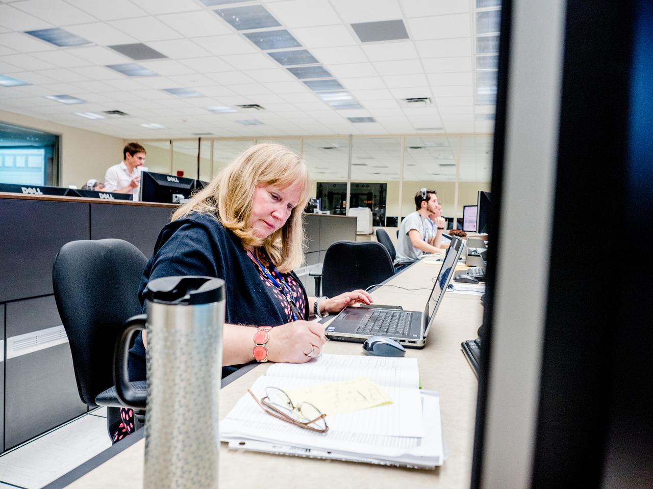
ARES 7 AXIS MILLING EQUIPMENT AND FACILITIES.
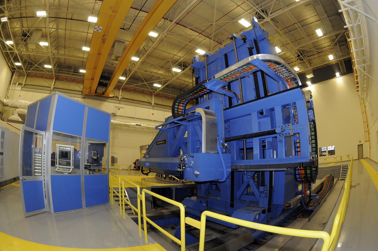
ARES 7 AXIS MILLING EQUIPMENT AND FACILITIES.

ARES 7 AXIS MILLING EQUIPMENT AND FACILITIES.
ARES 7 AXIS MILLING EQUIPMENT AND FACILITIES.
ARES 7 AXIS MILLING EQUIPMENT AND FACILITIES.
ARES 7 AXIS MILLING EQUIPMENT AND FACILITIES.
ARES 7 AXIS MILLING EQUIPMENT AND FACILITIES.
ARES 7 AXIS MILLING EQUIPMENT AND FACILITIES.
ARES 7 AXIS MILLING EQUIPMENT AND FACILITIES.
ARES 7 AXIS MILLING EQUIPMENT AND FACILITIES.
ARES 7 AXIS MILLING EQUIPMENT AND FACILITIES.
ARES 7 AXIS MILLING EQUIPMENT AND FACILITIES.
ARES 7 AXIS MILLING EQUIPMENT AND FACILITIES.
ARES 7 AXIS MILLING EQUIPMENT AND FACILITIES.
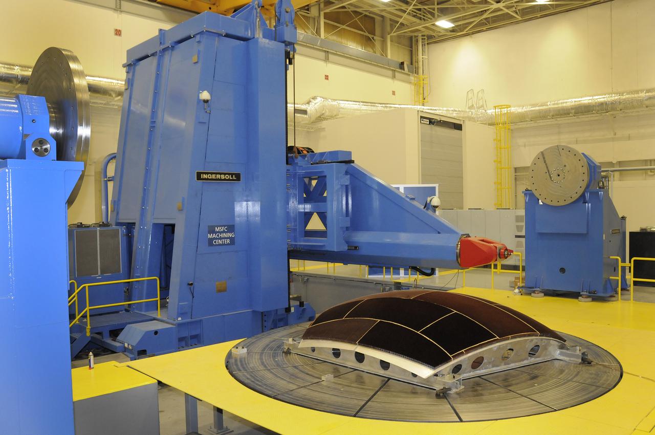
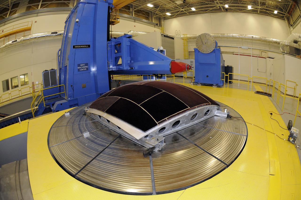
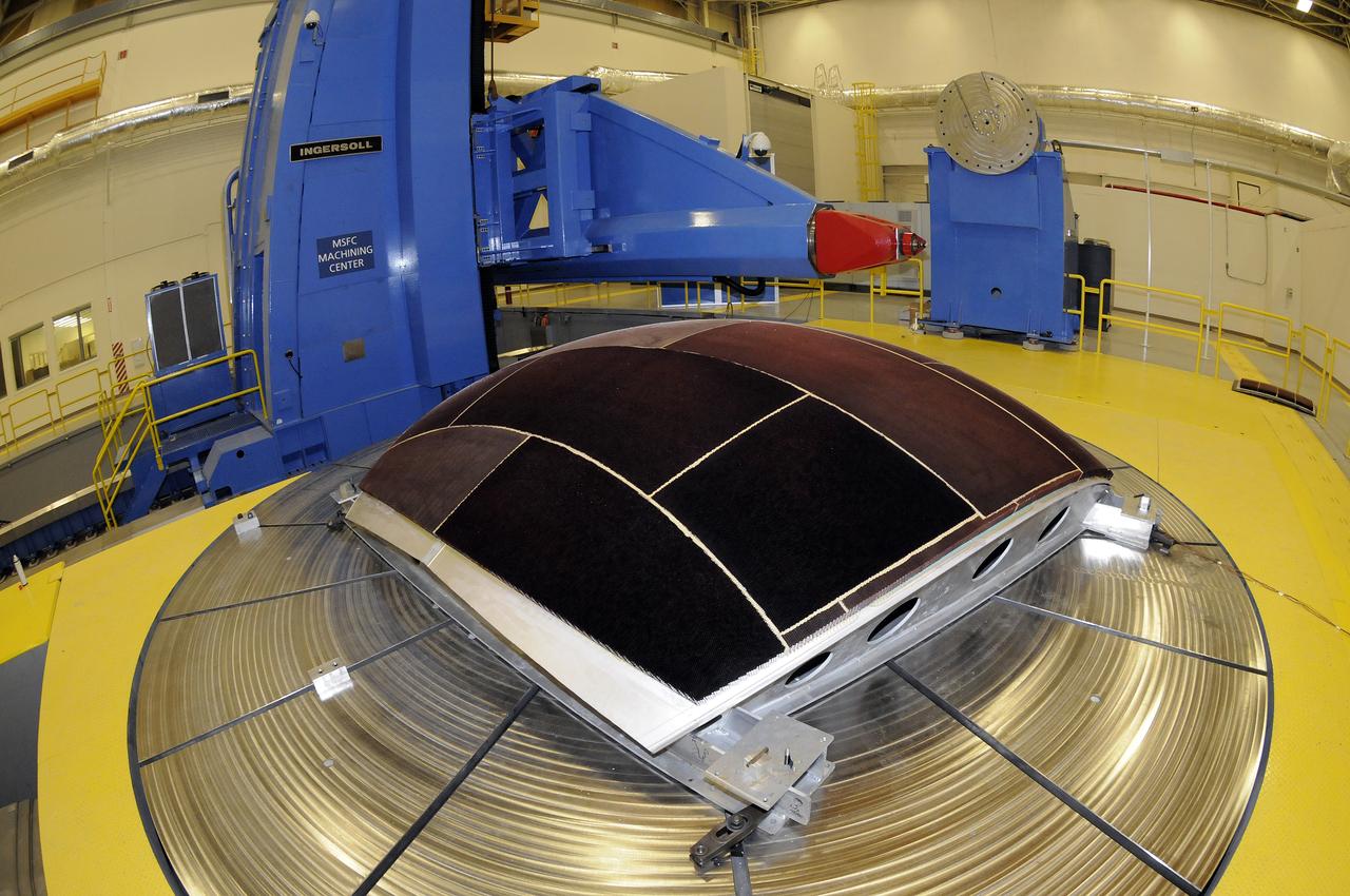
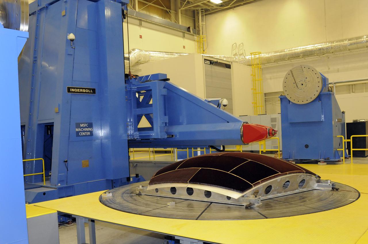
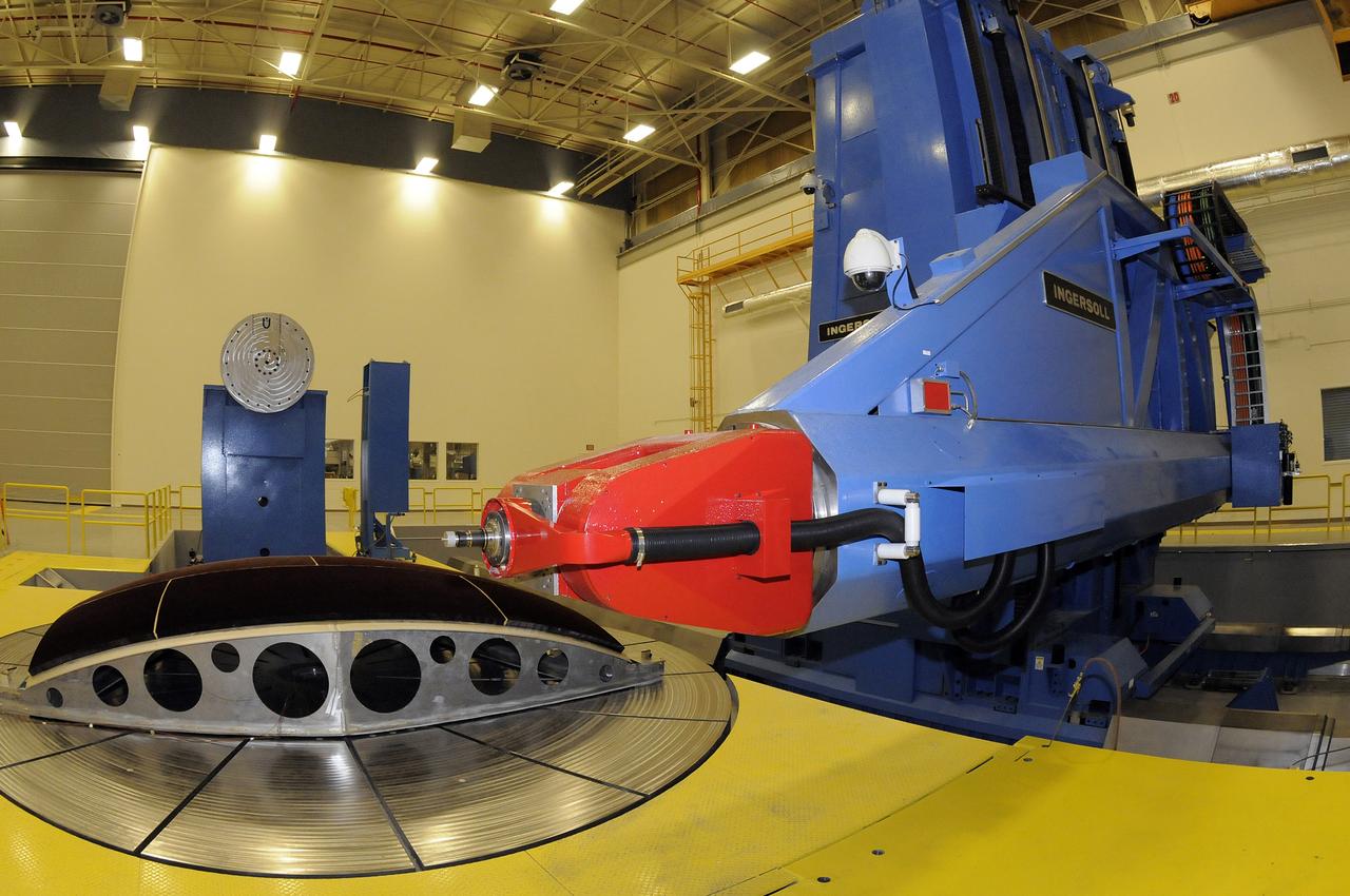
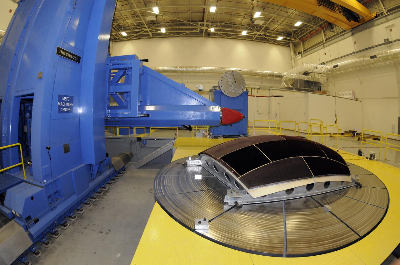
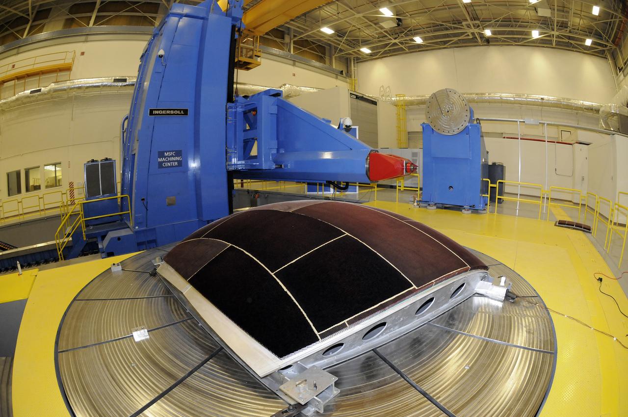
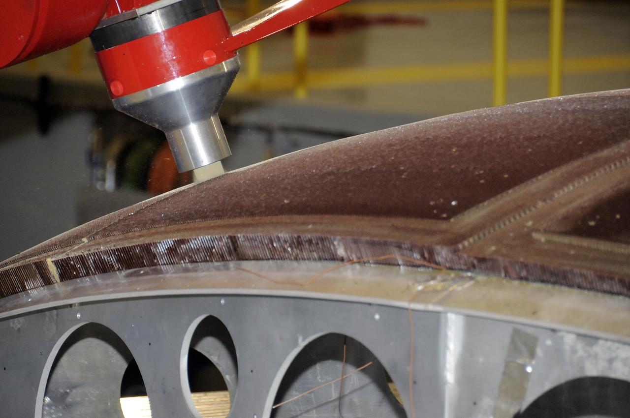
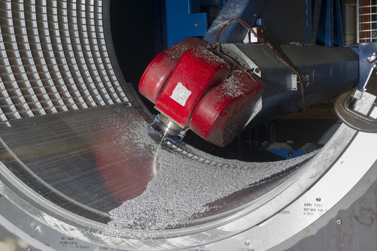
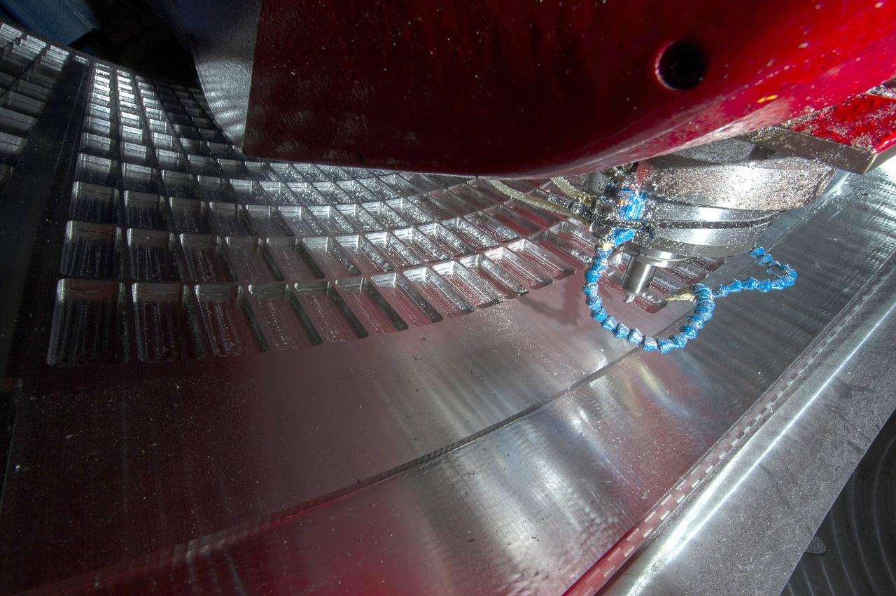
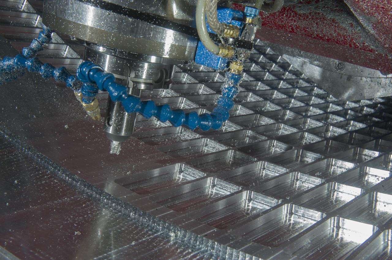
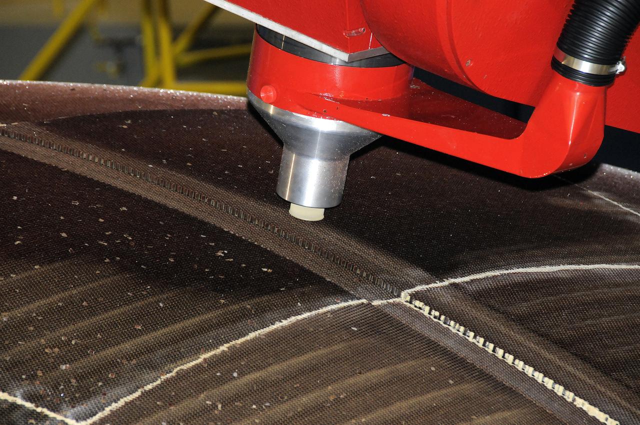
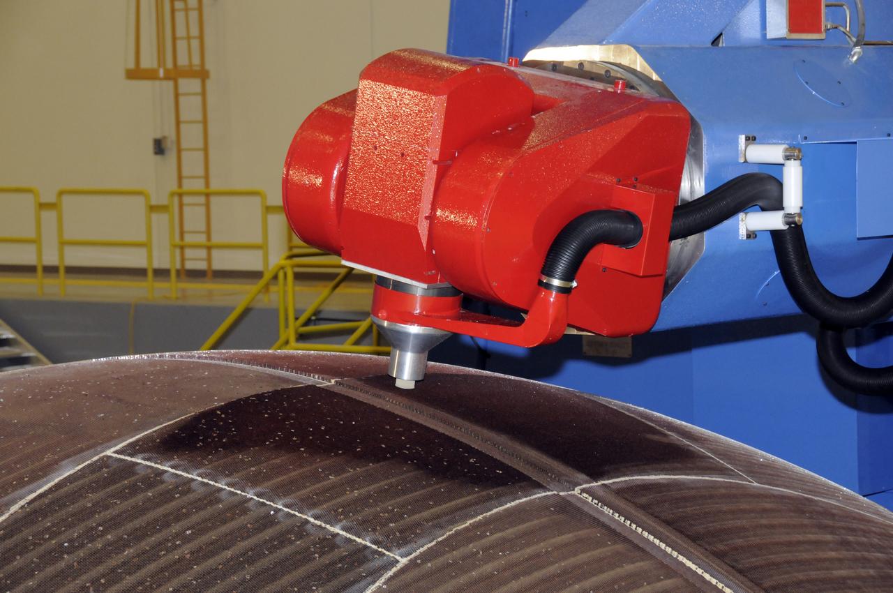
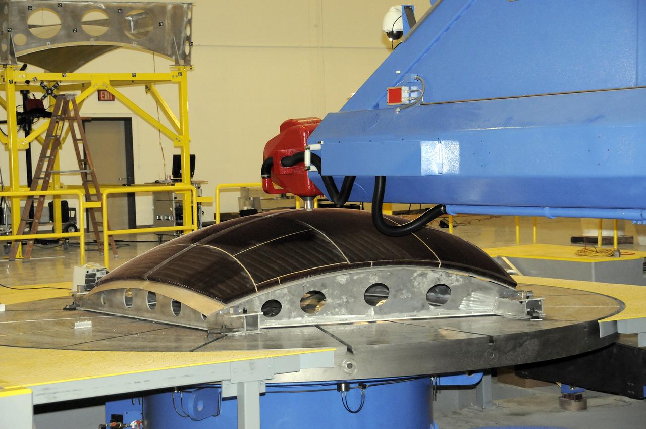
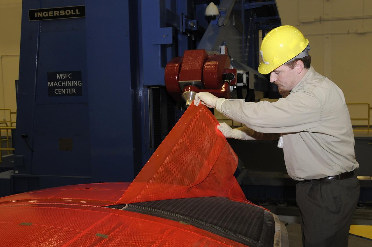
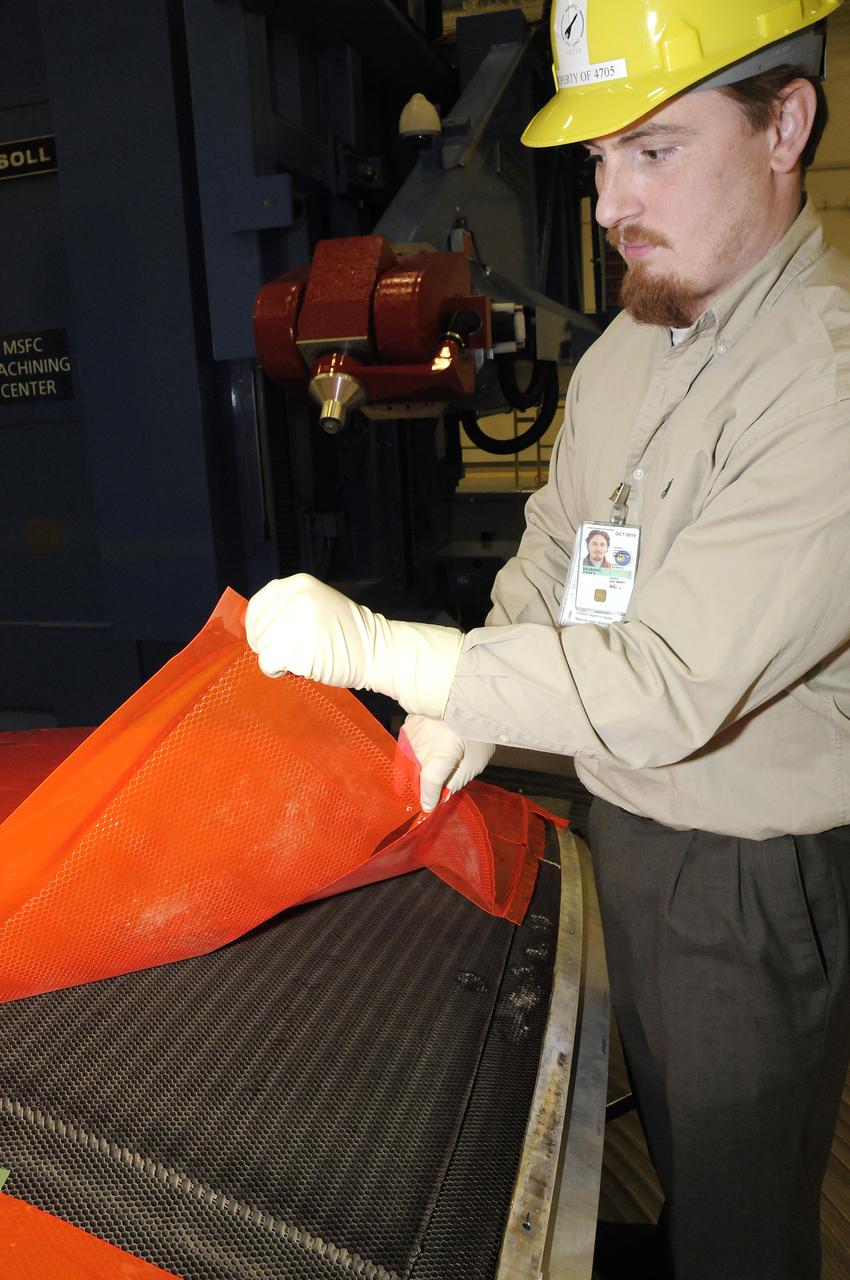
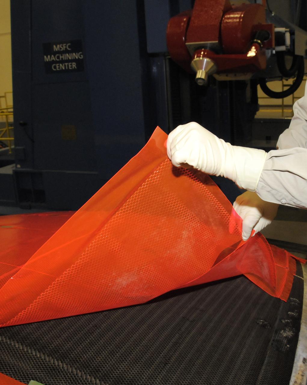
7-AXIS MILLING MACHINE PERFORMING THE ROUGH CUT ON THE 2ND QUARTER DOME DEMONSTRATION ARTICLE HONEYCOMB CORE
7-AXIS MILLING MACHINE PERFORMING THE ROUGH CUT ON THE 2ND QUARTER DOME DEMONSTRATION ARTICLE HONEYCOMB CORE
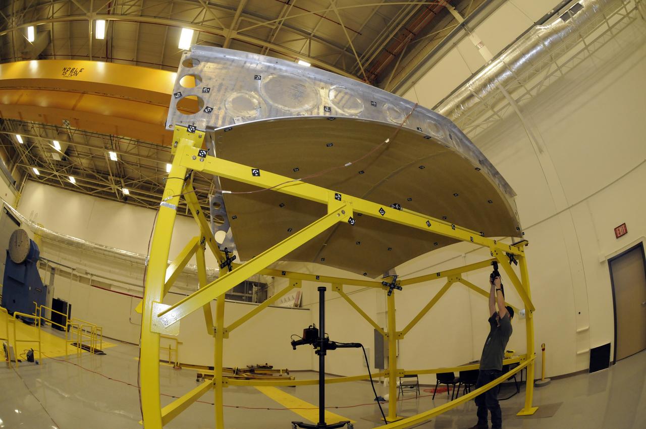
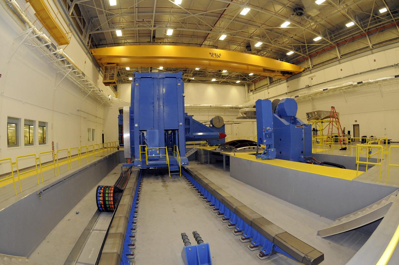
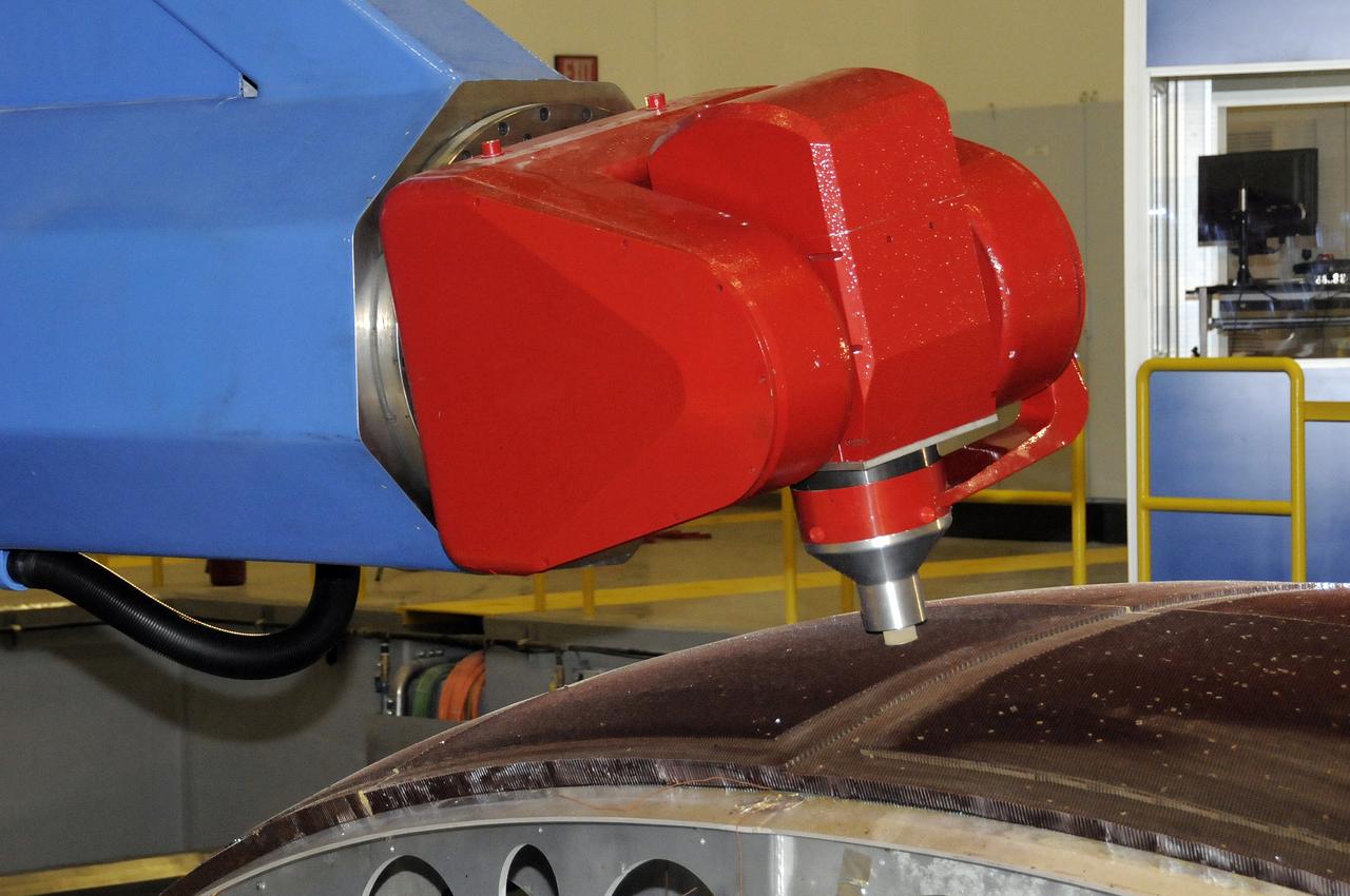
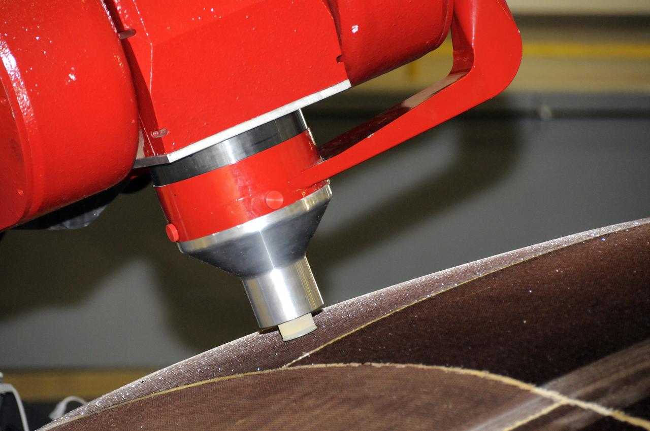
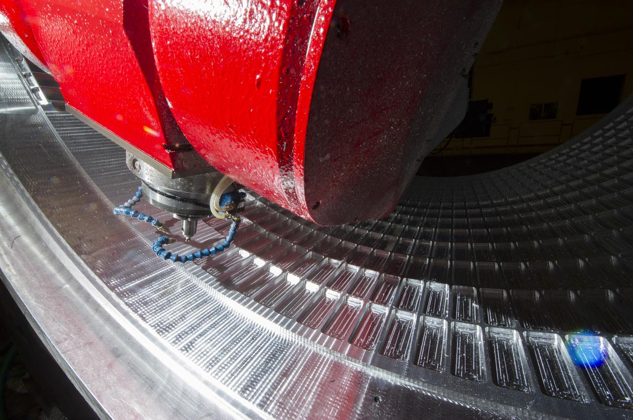
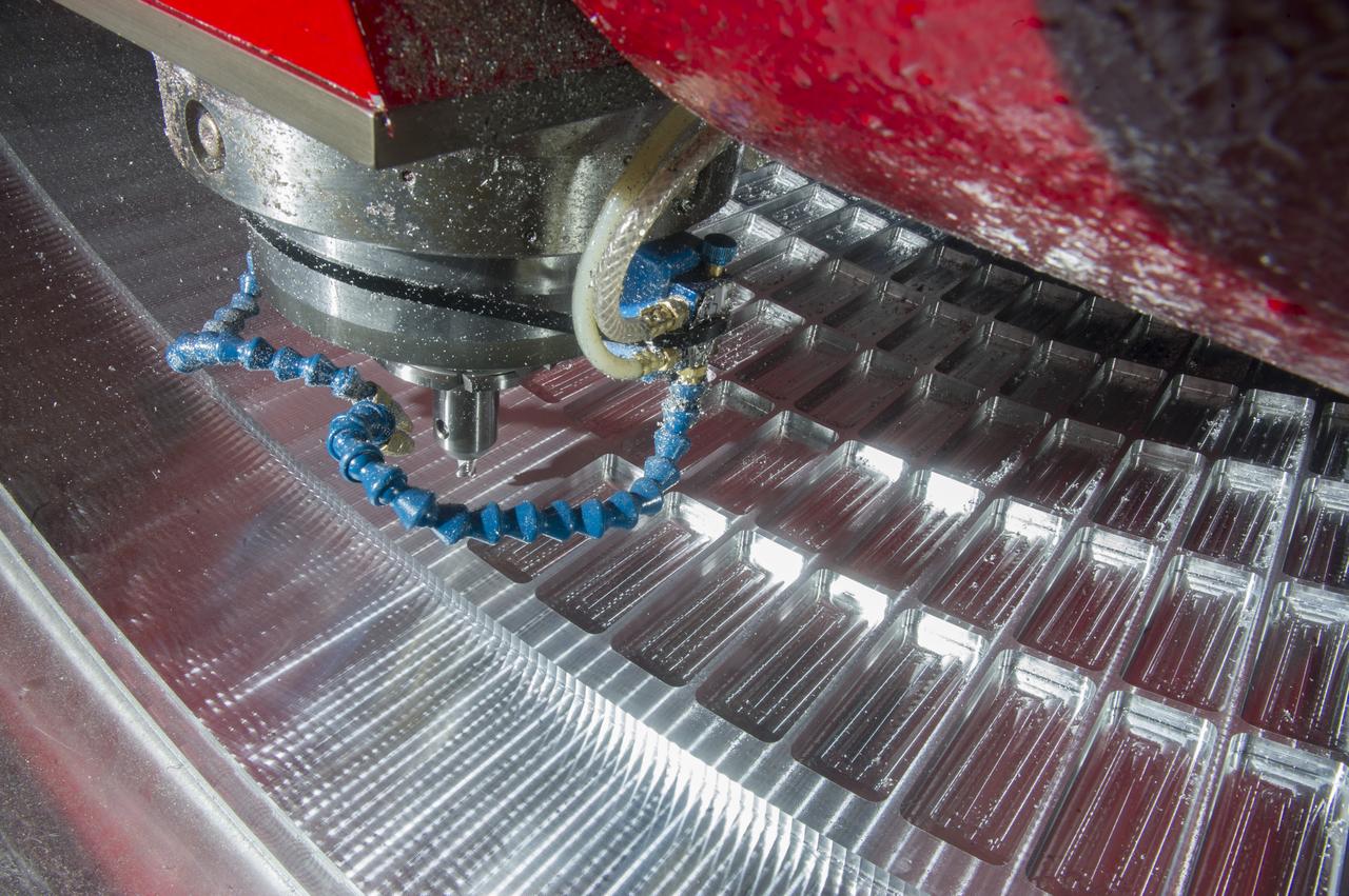
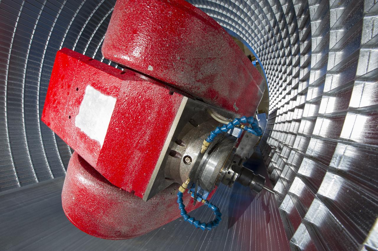
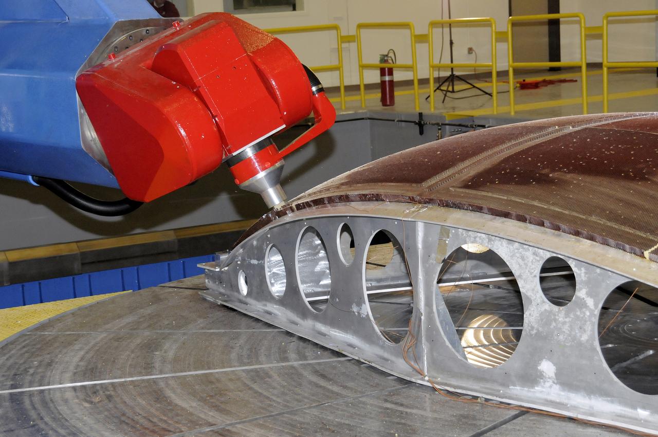
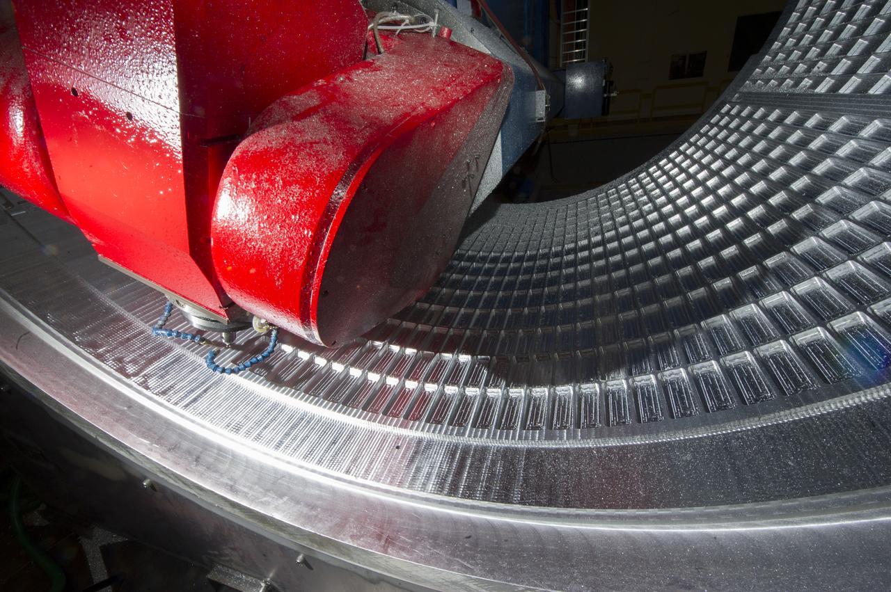
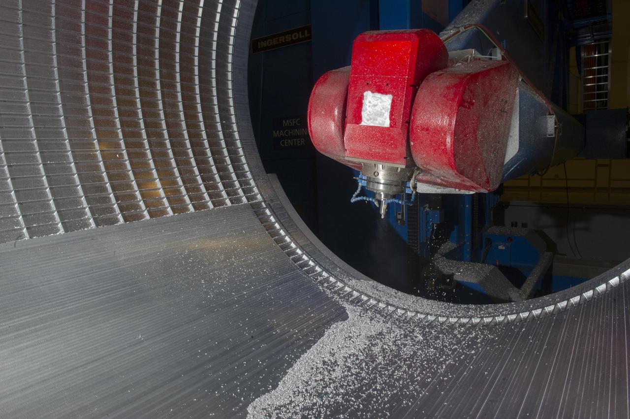
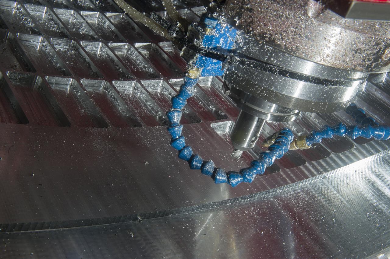
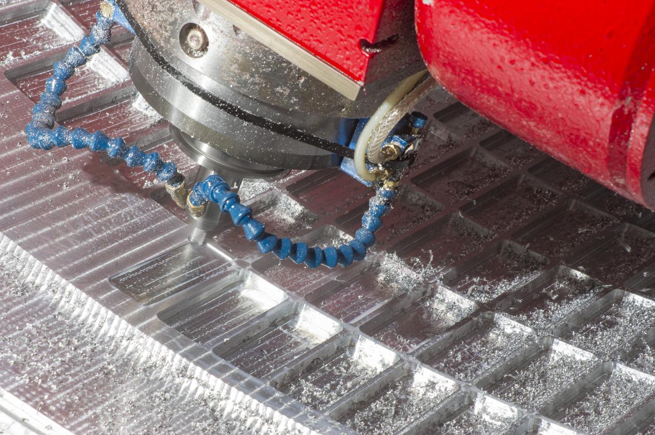
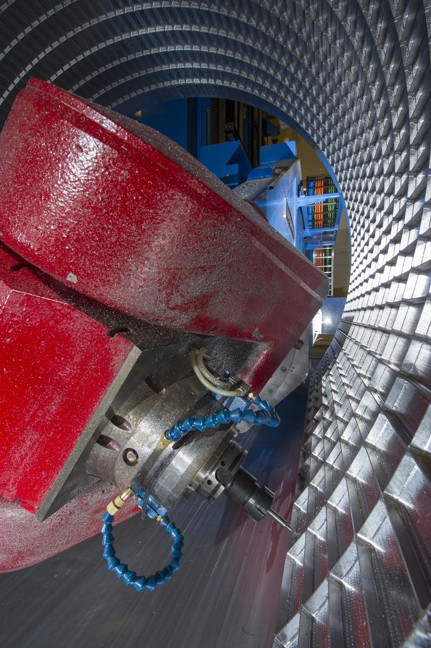
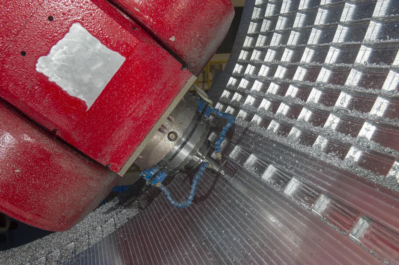
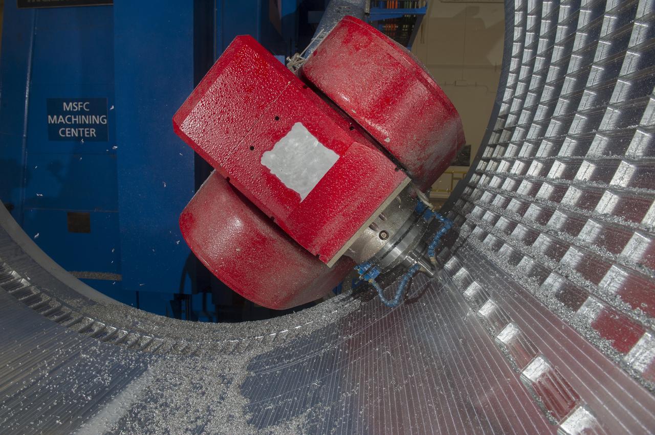
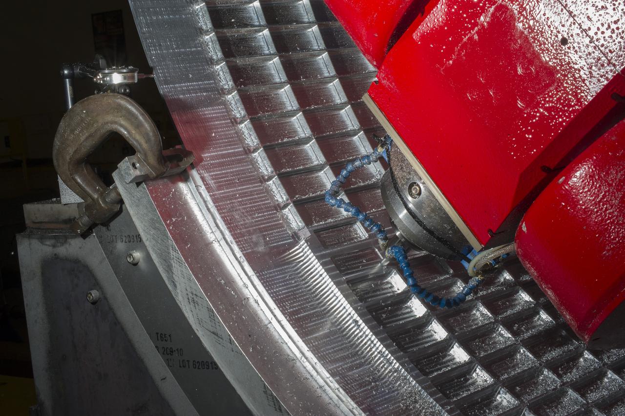
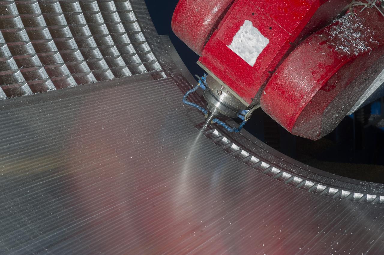
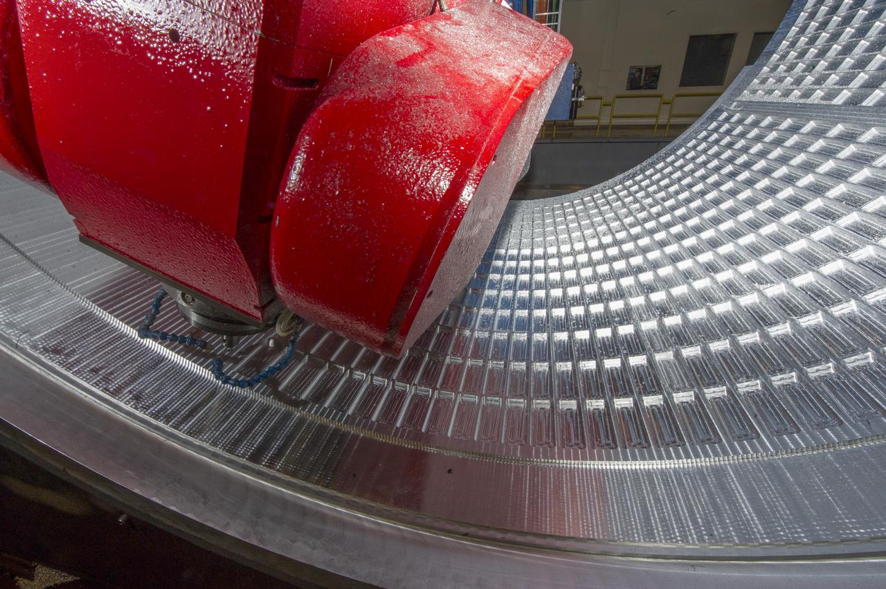
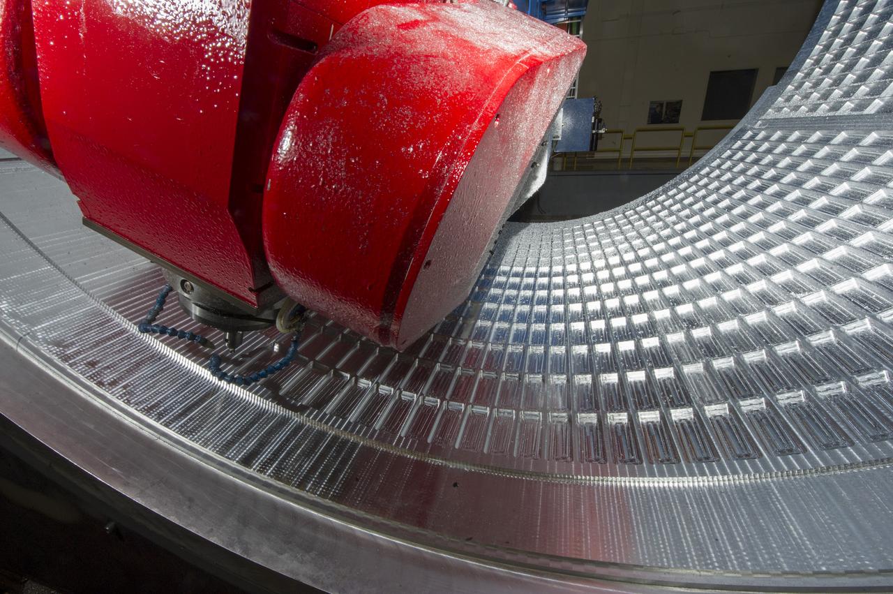
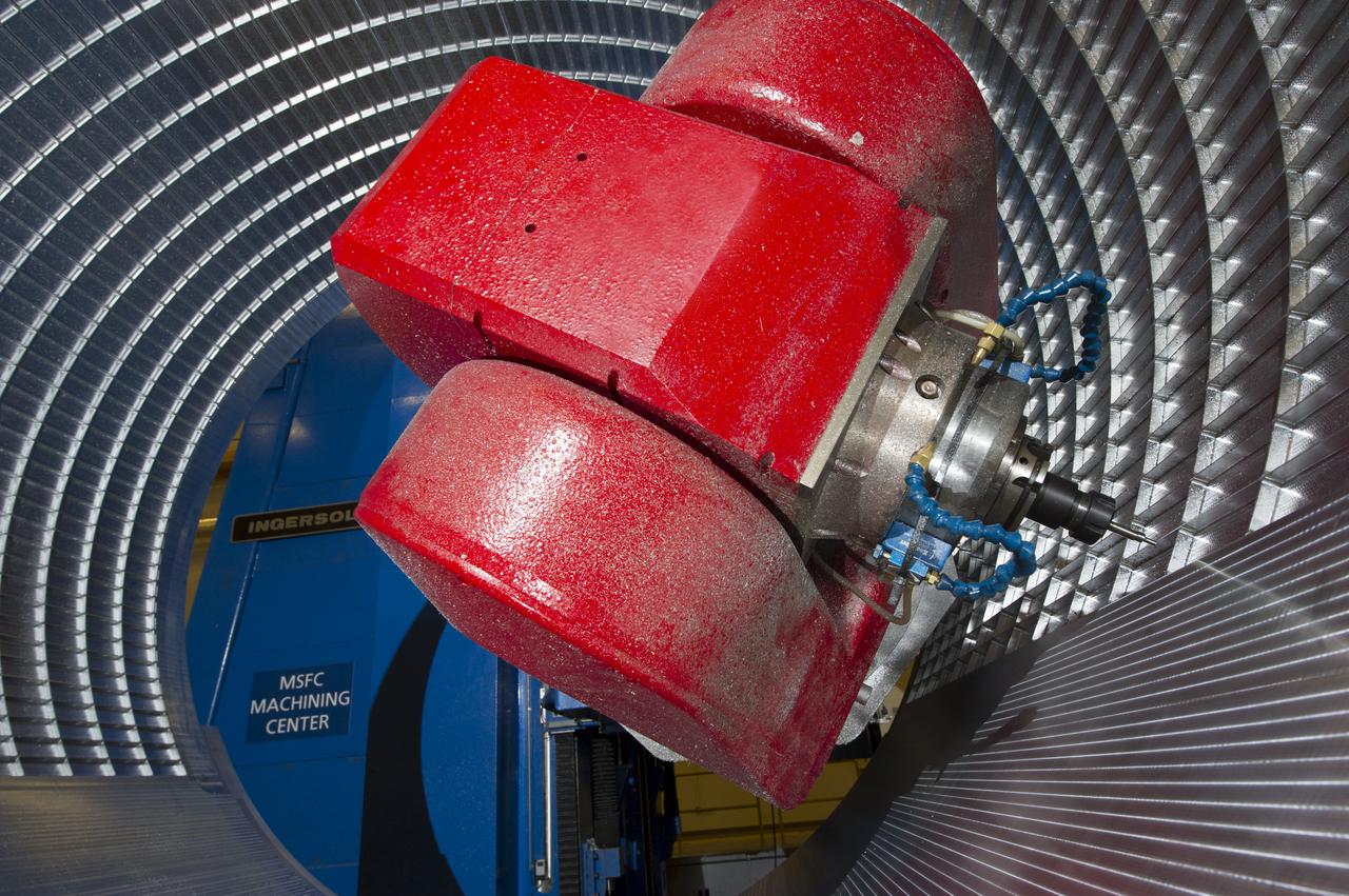
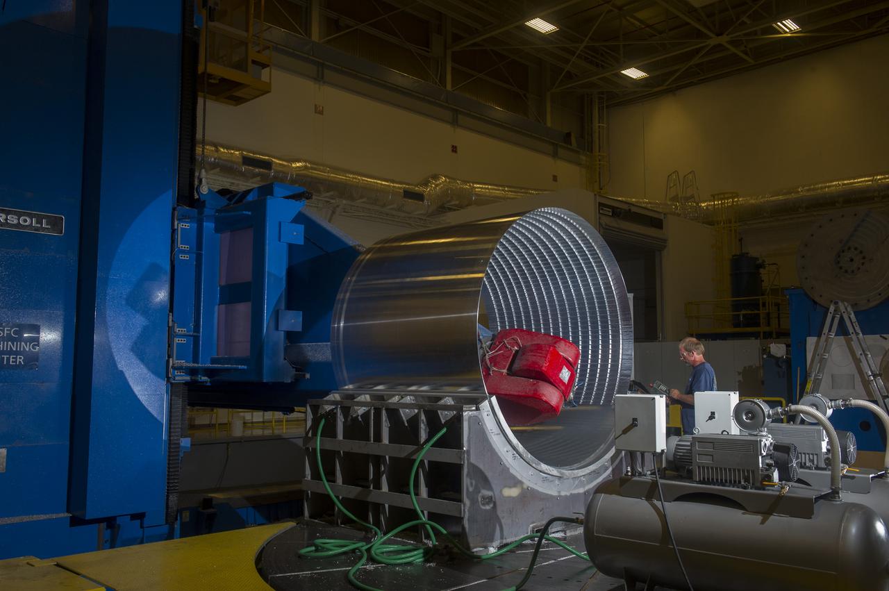
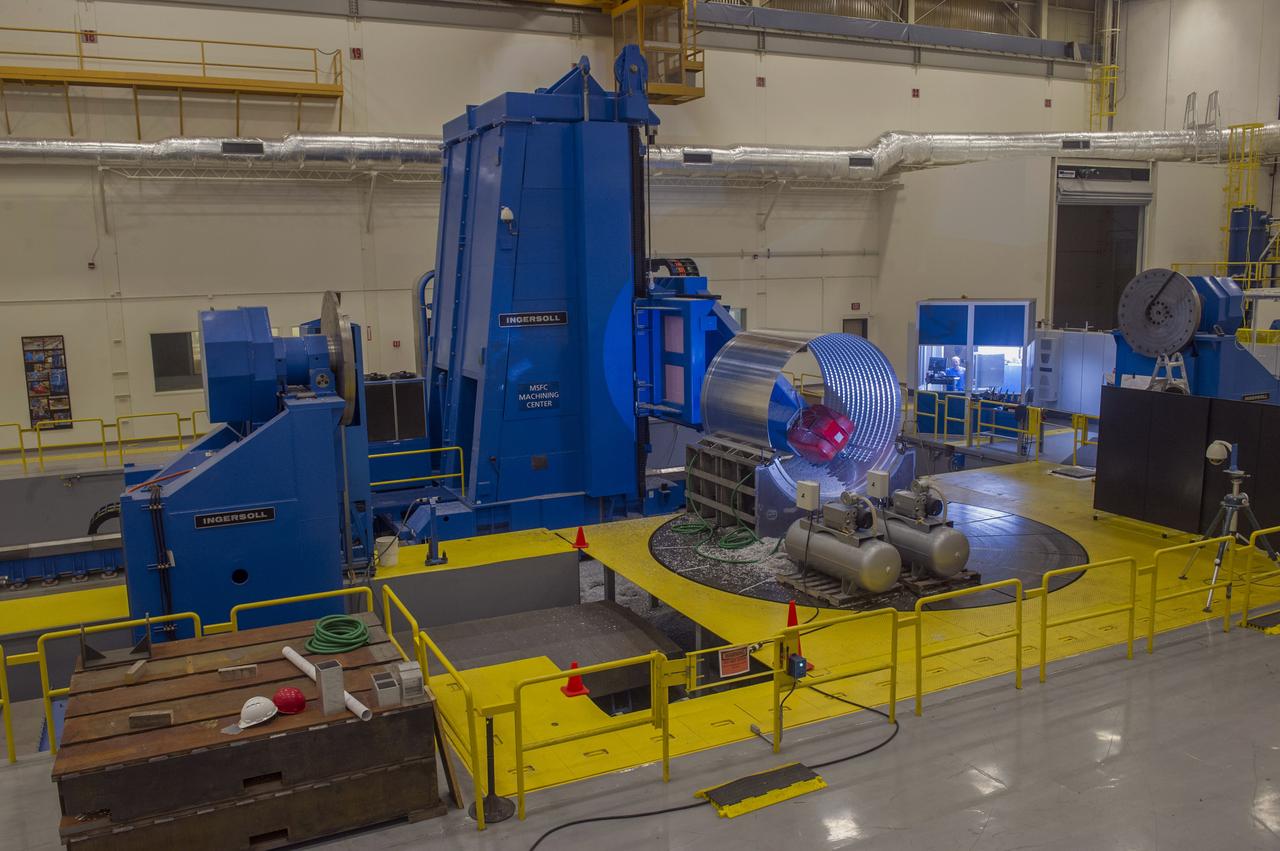
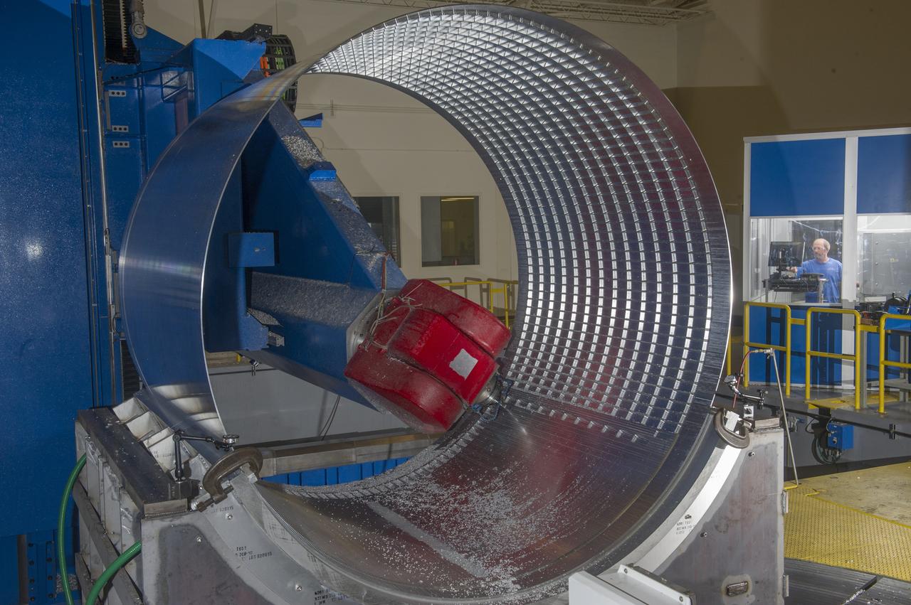
7-AXIS MILLING MACHINE CUTS ORTHOGRID TOOL PATH ON 8 FOOT CF1 BARREL IN SUPPORT OF SHELL BUCKLE TESTING
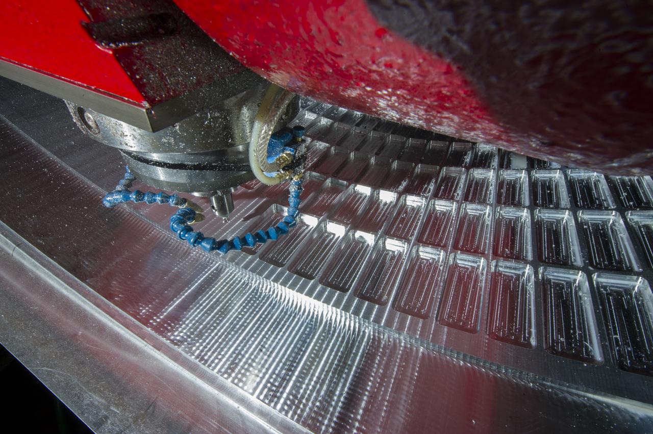
7-AXIS MILLING MACHINE CUTS ORTHOGRID TOOL PATH ON 8 FOOT CF1 BARREL IN SUPPORT OF SHELL BUCKLE TESTING
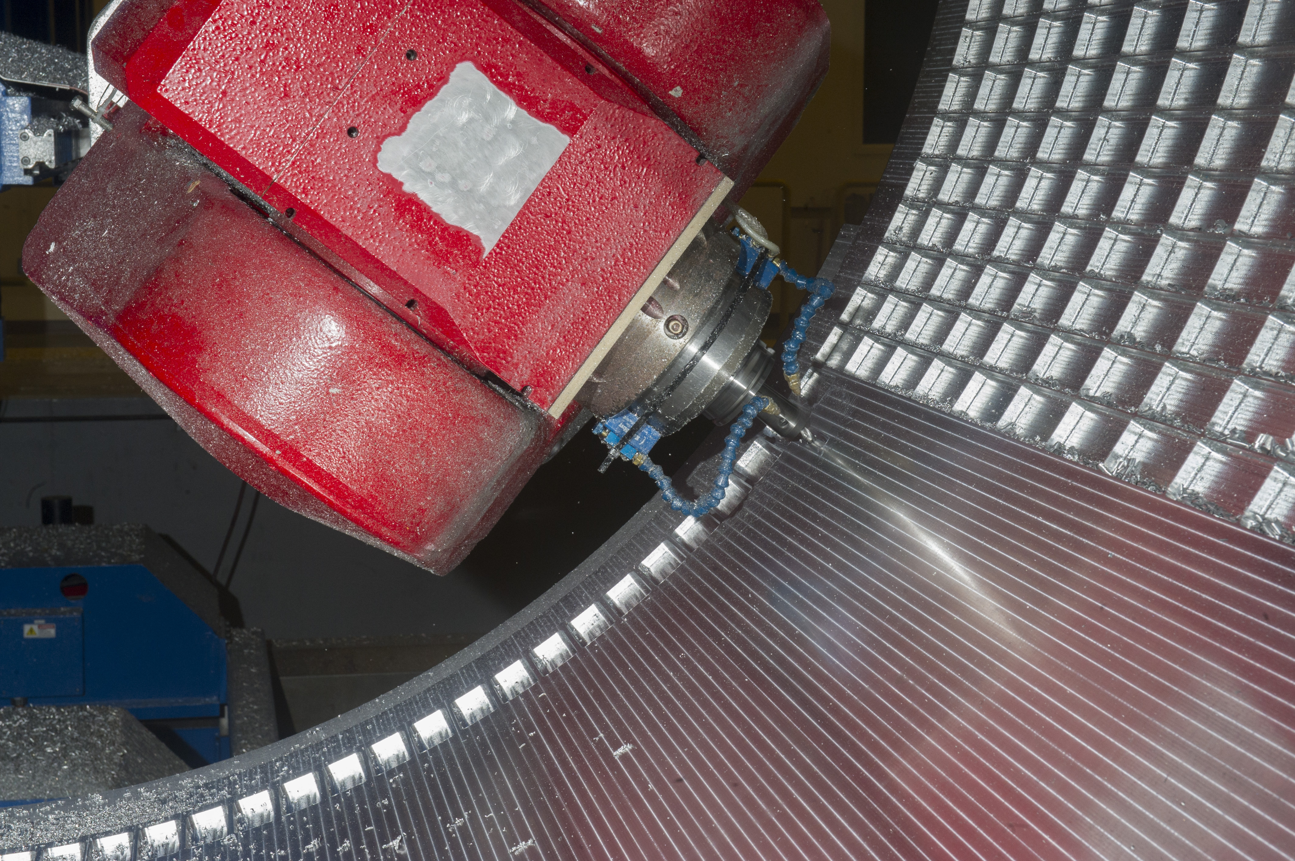
7-AXIS MILLING MACHINE CUTS ORTHOGRID TOOL PATH ON 8 FOOT CF1 BARREL IN SUPPORT OF SHELL BUCKLE TESTING

7-AXIS MILLING MACHINE CUTS ORTHOGRID TOOL PATH ON 8 FOOT CF1 BARREL IN SUPPORT OF SHELL BUCKLE TESTING
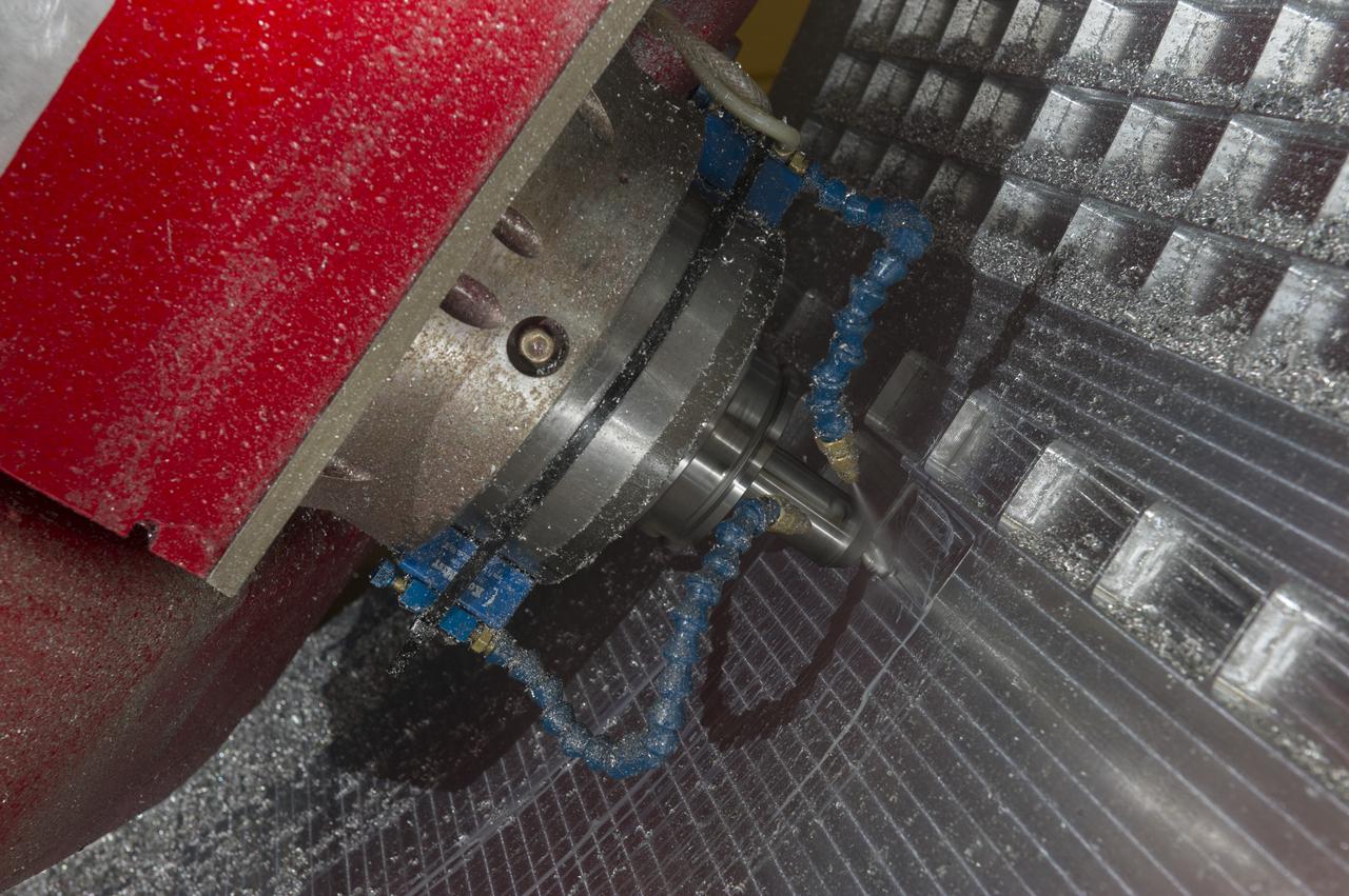
7-AXIS MILLING MACHINE CUTS ORTHOGRID TOOL PATH ON 8 FOOT CF1 BARREL IN SUPPORT OF SHELL BUCKLE TESTING
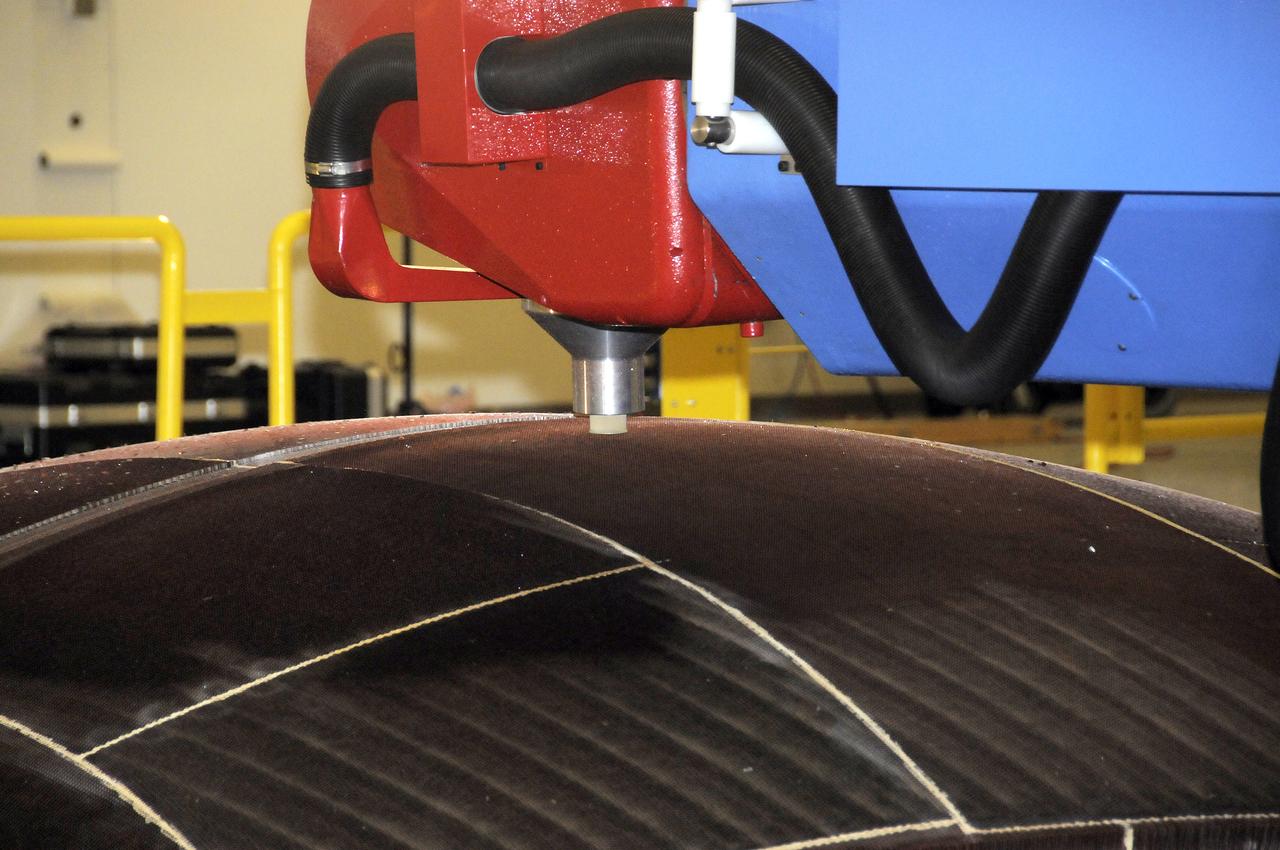
7-AXIS MILLING MACHINE PERFORMING THE ROUGH CUT ON THE 2ND QUARTER DOME DEMONSTRATION ARTICLE HONEYCOMB CORE
7-AXIS MILLING MACHINE CUTS ORTHOGRID TOOL PATH ON 8 FOOT CF1 BARREL IN SUPPORT OF SHELL BUCKLE TESTING
7-AXIS MILLING MACHINE CUTS ORTHOGRID TOOL PATH ON 8 FOOT CF1 BARREL IN SUPPORT OF SHELL BUCKLE TESTING
7-AXIS MILLING MACHINE CUTS ORTHOGRID TOOL PATH ON 8 FOOT CF1 BARREL IN SUPPORT OF SHELL BUCKLE TESTING
7-AXIS MILLING MACHINE PERFORMING THE ROUGH CUT ON THE 2ND QUARTER DOME DEMONSTRATION ARTICLE HONEYCOMB CORE
7-AXIS MILLING MACHINE CUTS ORTHOGRID TOOL PATH ON 8 FOOT CF1 BARREL IN SUPPORT OF SHELL BUCKLE TESTING
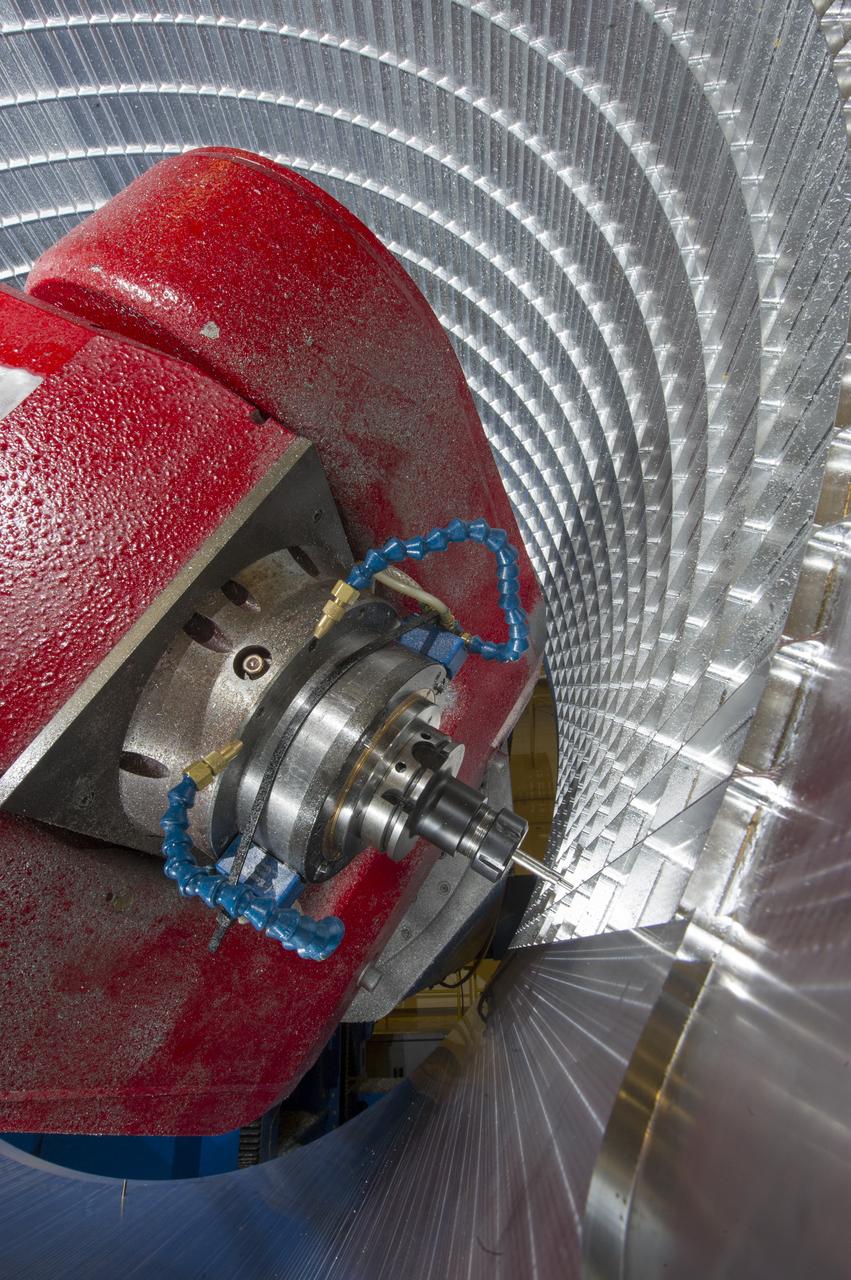
7-AXIS MILLING MACHINE CUTS ORTHOGRID TOOL PATH ON 8 FOOT CF1 BARREL IN SUPPORT OF SHELL BUCKLE TESTING
7-AXIS MILLING MACHINE PERFORMING THE ROUGH CUT ON THE 2ND QUARTER DOME DEMONSTRATION ARTICLE HONEYCOMB CORE
7-AXIS MILLING MACHINE CUTS ORTHOGRID TOOL PATH ON 8 FOOT CF1 BARREL IN SUPPORT OF SHELL BUCKLE TESTING
7-AXIS MILLING MACHINE CUTS ORTHOGRID TOOL PATH ON 8 FOOT CF1 BARREL IN SUPPORT OF SHELL BUCKLE TESTING
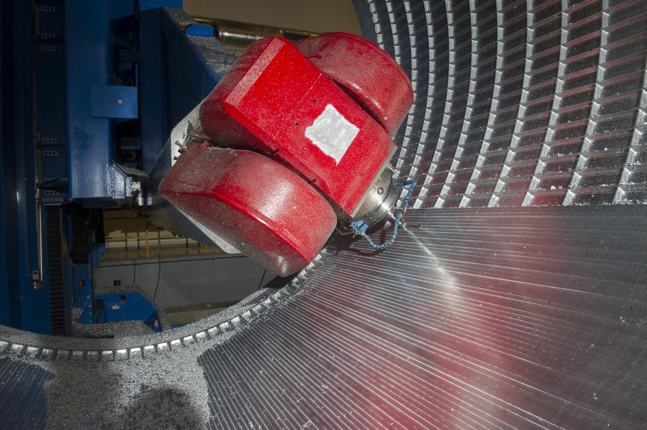
7-AXIS MILLING MACHINE CUTS ORTHOGRID TOOL PATH ON 8 FOOT CF1 BARREL IN SUPPORT OF SHELL BUCKLE TESTING
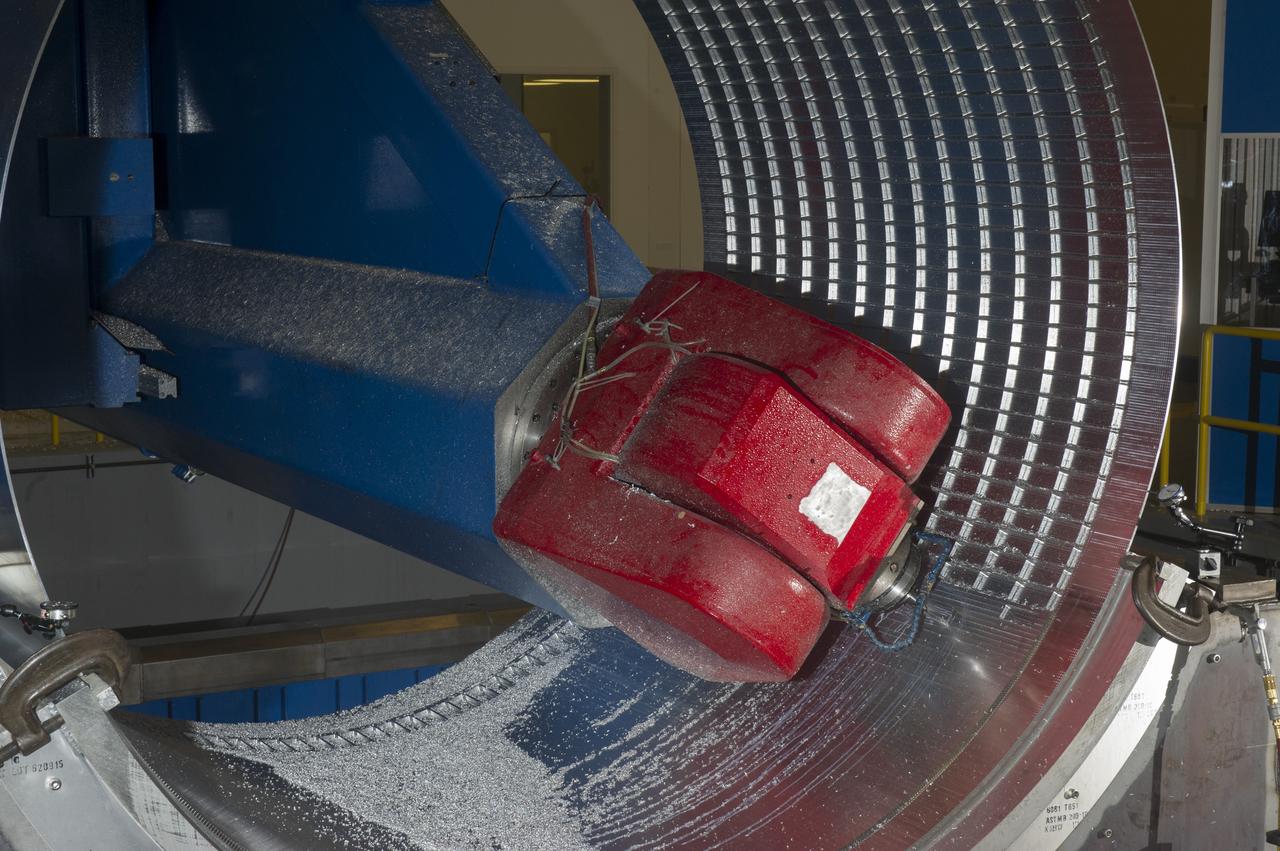
7-AXIS MILLING MACHINE CUTS ORTHOGRID TOOL PATH ON 8 FOOT CF1 BARREL IN SUPPORT OF SHELL BUCKLE TESTING
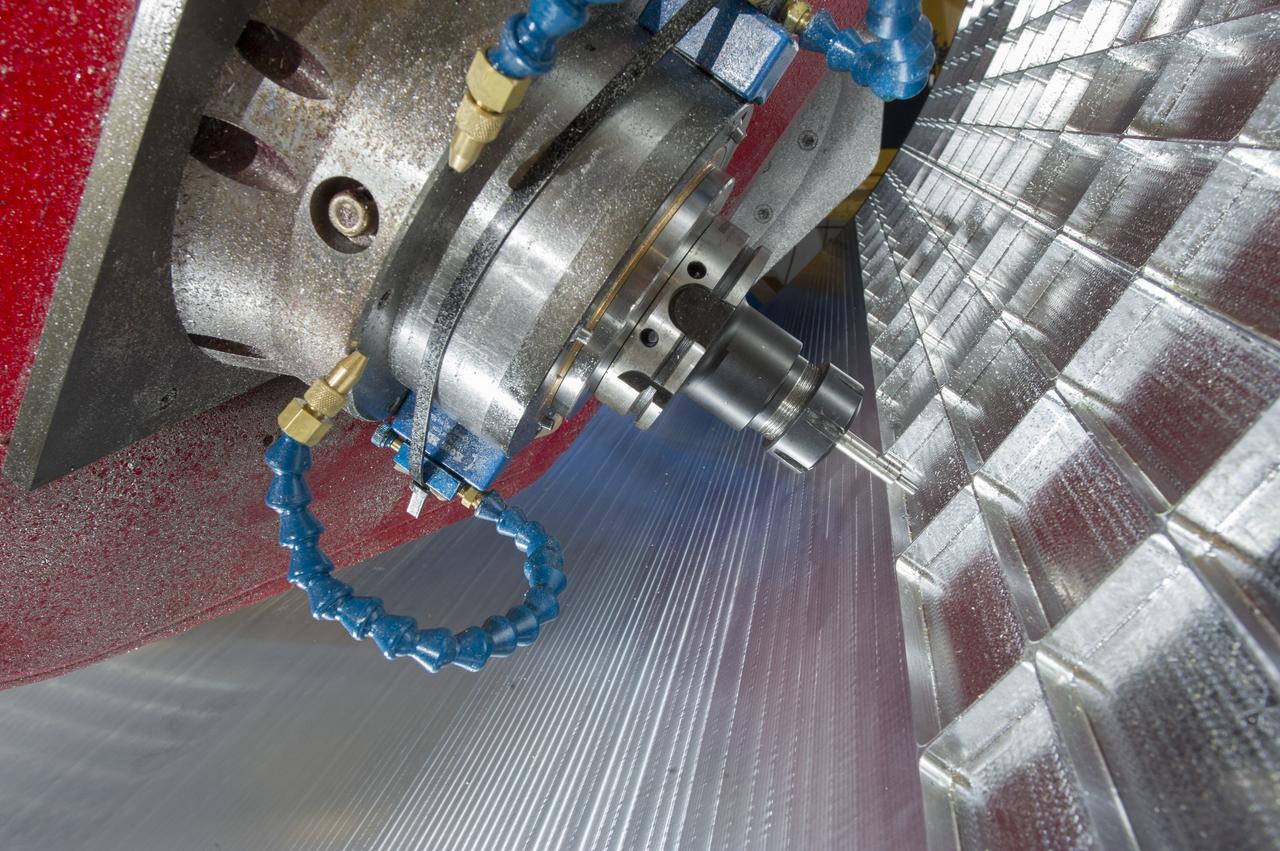
7-AXIS MILLING MACHINE CUTS ORTHOGRID TOOL PATH ON 8 FOOT CF1 BARREL IN SUPPORT OF SHELL BUCKLE TESTING
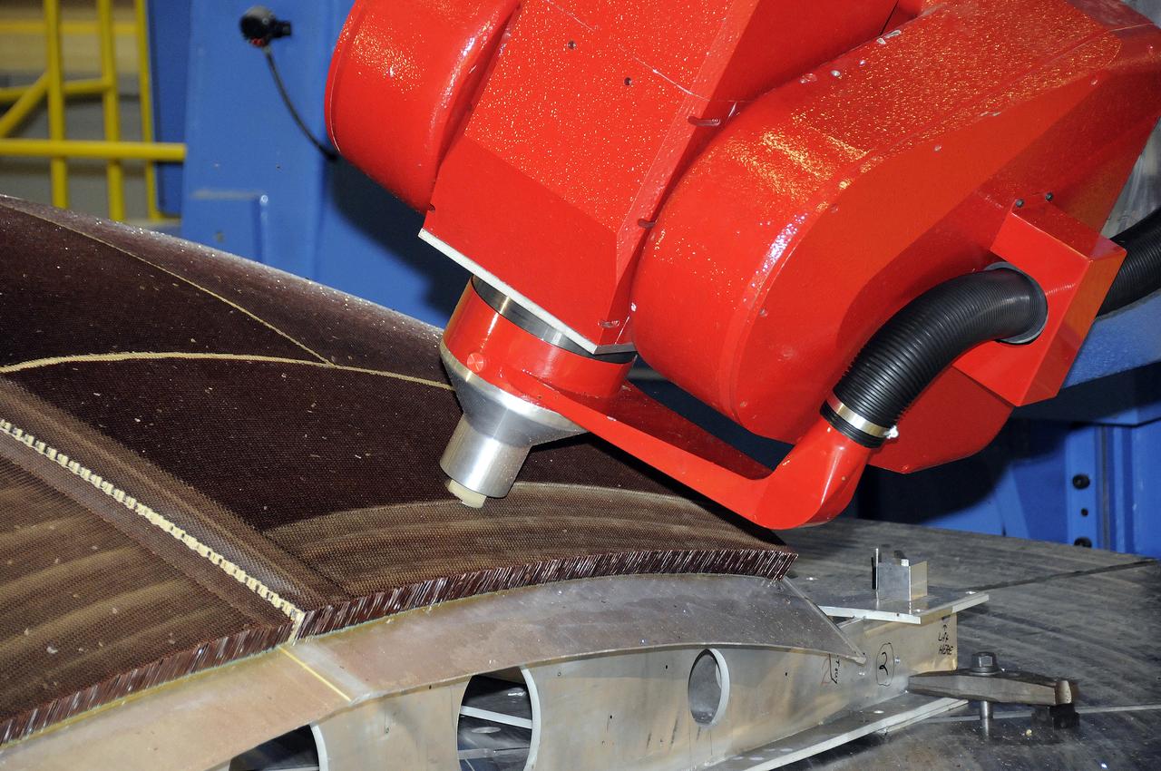
7-AXIS MILLING MACHINE PERFORMING THE ROUGH CUT ON THE 2ND QUARTER DOME DEMONSTRATION ARTICLE HONEYCOMB CORE
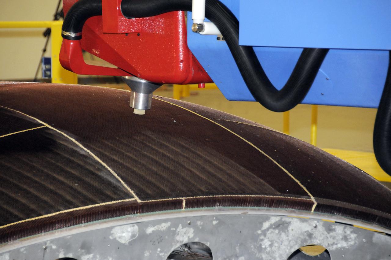
7-AXIS MILLING MACHINE PERFORMING THE ROUGH CUT ON THE 2ND QUARTER DOME DEMONSTRATION ARTICLE HONEYCOMB CORE
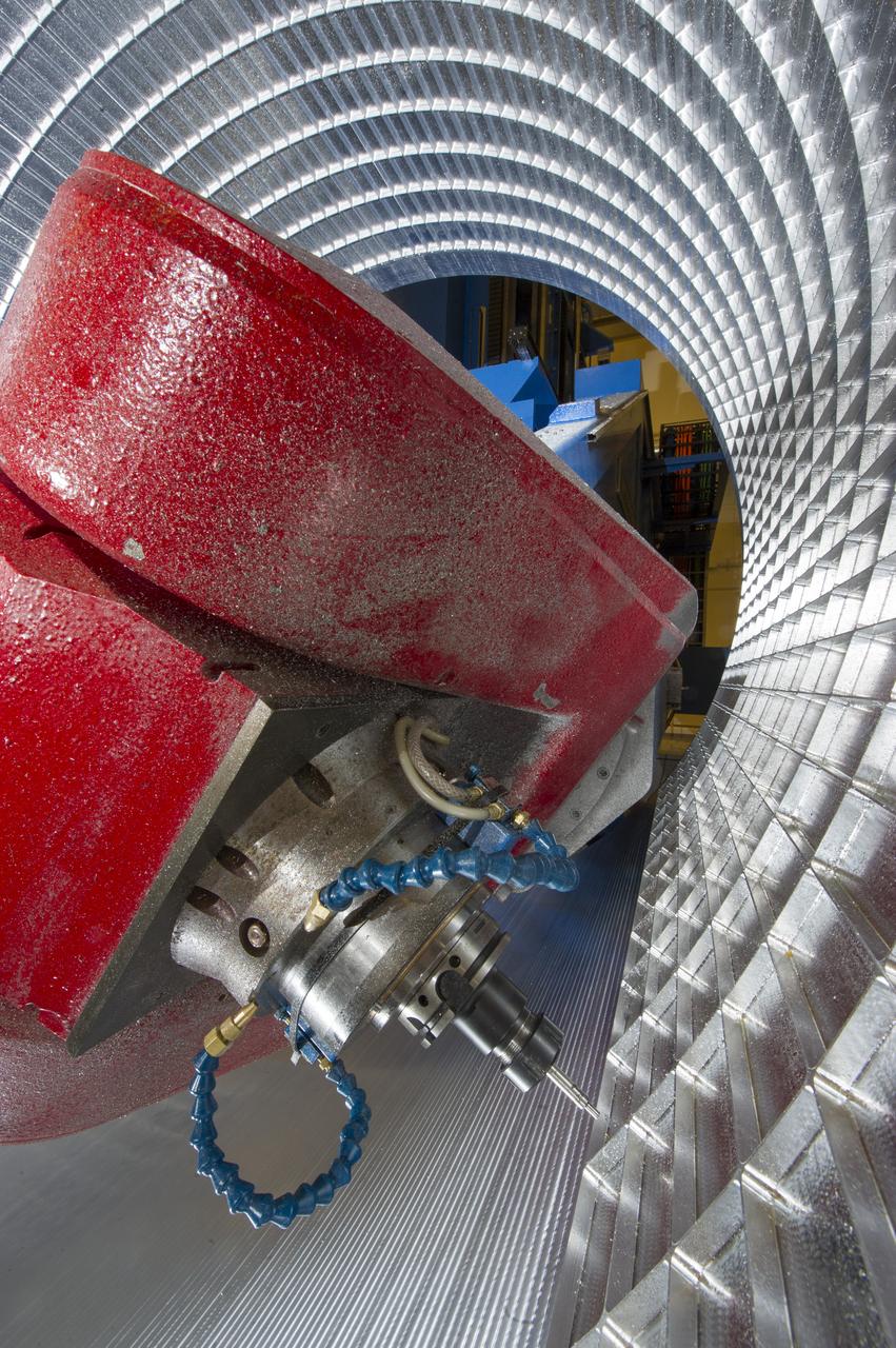
7-AXIS MILLING MACHINE CUTS ORTHOGRID TOOL PATH ON 8 FOOT CF1 BARREL IN SUPPORT OF SHELL BUCKLE TESTING
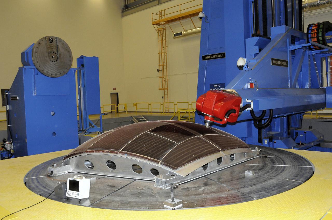
7-AXIS MILLING MACHINE PERFORMING THE ROUGH CUT ON THE 2ND QUARTER DOME DEMONSTRATION ARTICLE HONEYCOMB CORE
7-AXIS MILLING MACHINE PERFORMING THE ROUGH CUT ON THE 2ND QUARTER DOME DEMONSTRATION ARTICLE HONEYCOMB CORE
7-AXIS MILLING MACHINE PERFORMING THE ROUGH CUT ON THE 2ND QUARTER DOME DEMONSTRATION ARTICLE HONEYCOMB CORE
7-AXIS MILLING MACHINE PERFORMING THE ROUGH CUT ON THE 2ND QUARTER DOME DEMONSTRATION ARTICLE HONEYCOMB CORE
7-AXIS MILLING MACHINE CUTS ORTHOGRID TOOL PATH ON 8 FOOT CF1 BARREL IN SUPPORT OF SHELL BUCKLE TESTING

7-AXIS MILLING MACHINE PERFORMING THE ROUGH CUT ON THE 2ND QUARTER DOME DEMONSTRATION ARTICLE HONEYCOMB CORE
7-AXIS MILLING MACHINE CUTS ORTHOGRID TOOL PATH ON 8 FOOT CF1 BARREL IN SUPPORT OF SHELL BUCKLE TESTING
7-AXIS MILLING MACHINE PERFORMING THE ROUGH CUT ON THE 2ND QUARTER DOME DEMONSTRATION ARTICLE HONEYCOMB CORE
7-AXIS MILLING MACHINE CUTS ORTHOGRID TOOL PATH ON 8 FOOT CF1 BARREL IN SUPPORT OF SHELL BUCKLE TESTING
7-AXIS MILLING MACHINE CUTS ORTHOGRID TOOL PATH ON 8 FOOT CF1 BARREL IN SUPPORT OF SHELL BUCKLE TESTING
7-AXIS MILLING MACHINE CUTS ORTHOGRID TOOL PATH ON 8 FOOT CF1 BARREL IN SUPPORT OF SHELL BUCKLE TESTING
7-AXIS MILLING MACHINE CUTS ORTHOGRID TOOL PATH ON 8 FOOT CF1 BARREL IN SUPPORT OF SHELL BUCKLE TESTING

7-AXIS MILLING MACHINE PERFORMING THE ROUGH CUT ON THE 2ND QUARTER DOME DEMONSTRATION ARTICLE HONEYCOMB CORE
7-AXIS MILLING MACHINE CUTS ORTHOGRID TOOL PATH ON 8 FOOT CF1 BARREL IN SUPPORT OF SHELL BUCKLE TESTING

7-AXIS MILLING MACHINE PERFORMING THE ROUGH CUT ON THE 2ND QUARTER DOME DEMONSTRATION ARTICLE HONEYCOMB CORE
7-AXIS MILLING MACHINE CUTS ORTHOGRID TOOL PATH ON 8 FOOT CF1 BARREL IN SUPPORT OF SHELL BUCKLE TESTING
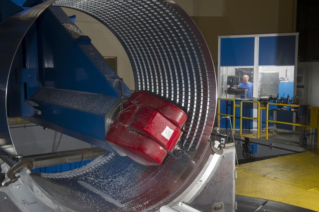
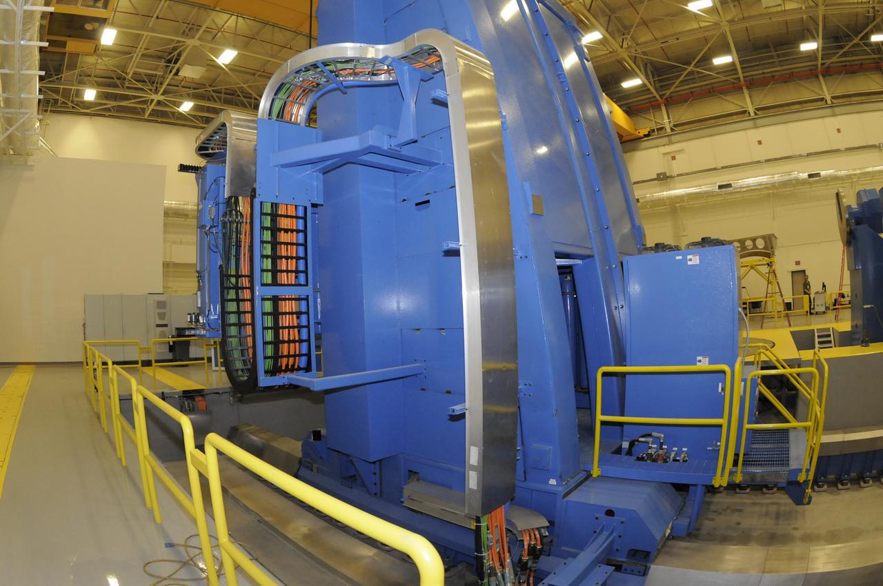
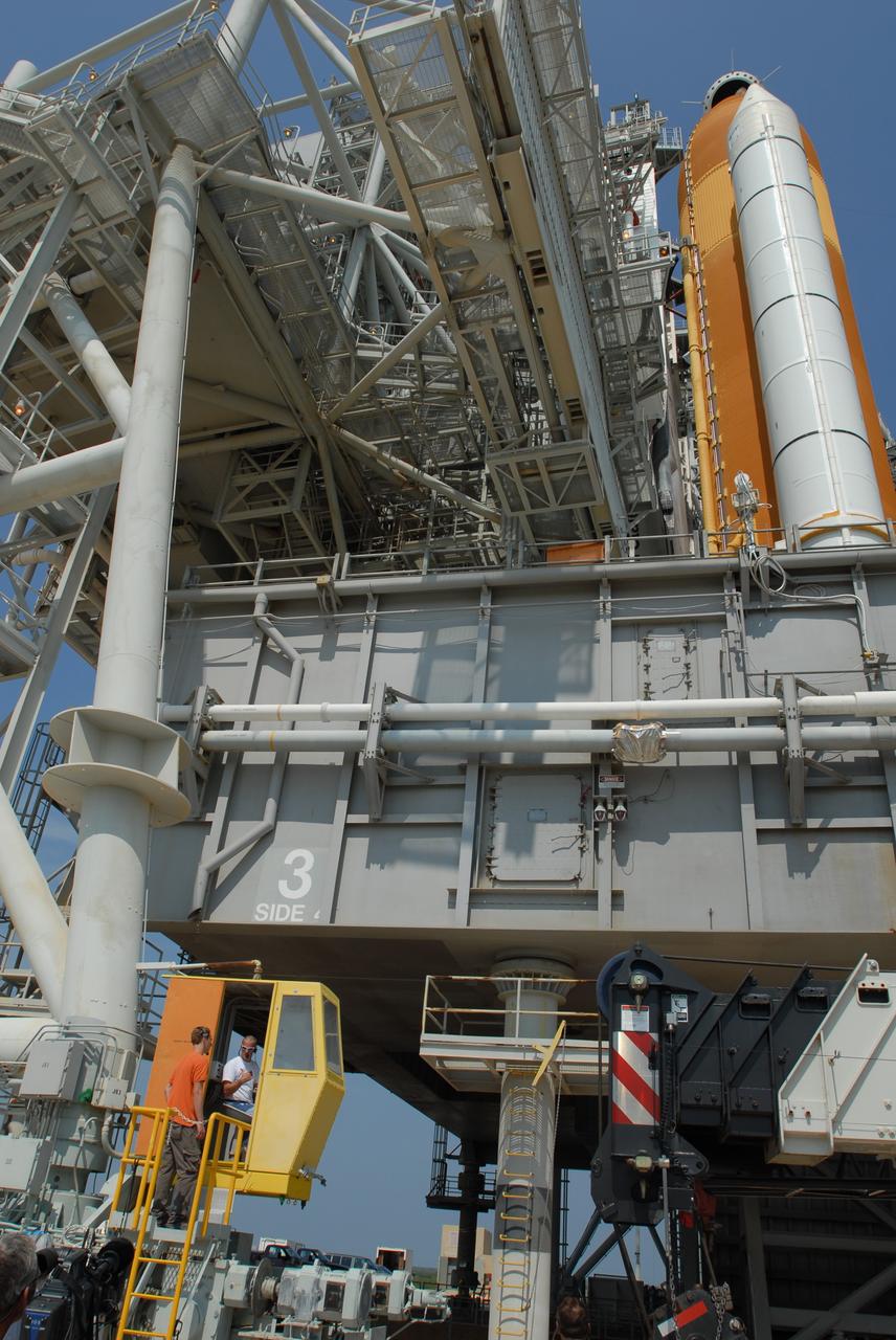
DAVID OSBORNE, A MACHINIST ON THE METTS CONTRACT, OPERATES THE 7-AXIS MILLING MACHINE WITH CF1 BARREL BEING PREPARED FOR SHELL BUCKLE TESTING
DAVID OSBORNE, A MACHINIST ON THE METTS CONTRACT, OPERATES THE 7-AXIS MILLING MACHINE WITH CF1 BARREL BEING PREPARED FOR SHELL BUCKLE TESTING
DAVID OSBORNE, A MACHINIST ON THE METTS CONTRACT, OPERATES THE 7-AXIS MILLING MACHINE WITH CF1 BARREL BEING PREPARED FOR SHELL BUCKLE TESTING
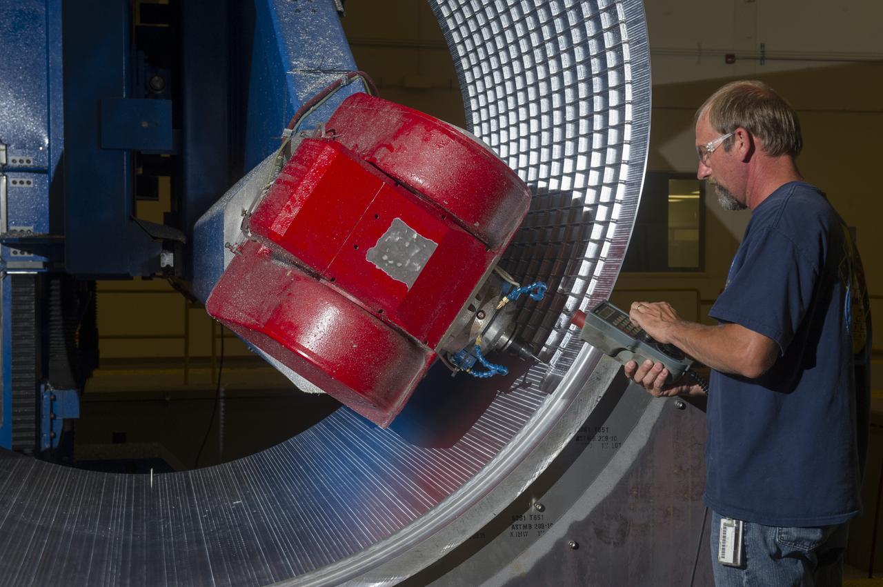
DAVID OSBORNE, A MACHINIST ON THE METTS CONTRACT, OPERATES THE 7-AXIS MILLING MACHINE WITH CF1 BARREL BEING PREPARED FOR SHELL BUCKLE TESTING
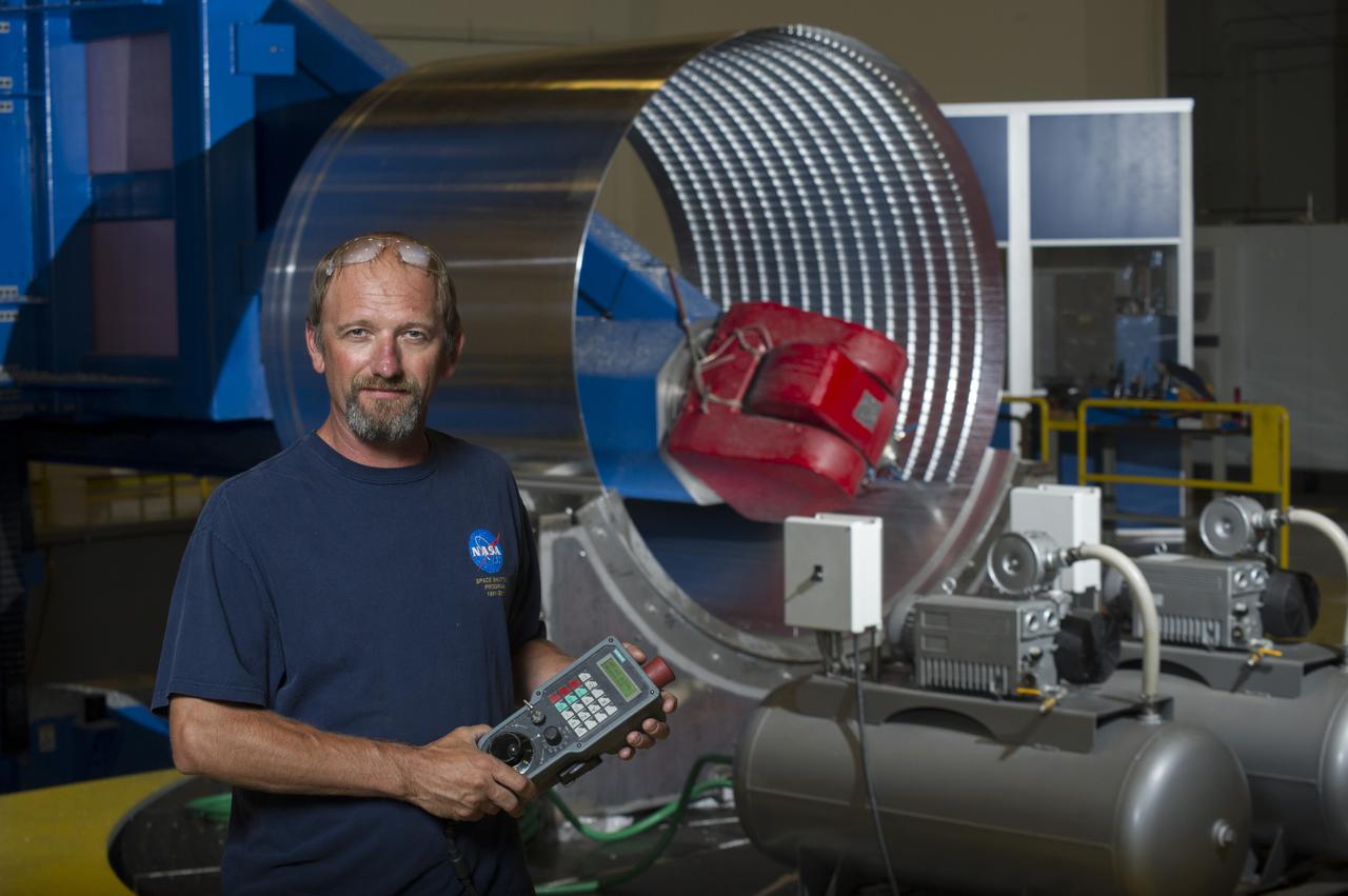
DAVID OSBORNE, A MACHINIST ON THE METTS CONTRACT, OPERATES THE 7-AXIS MILLING MACHINE WITH CF1 BARREL BEING PREPARED FOR SHELL BUCKLE TESTING
DAVID OSBORNE, A MACHINIST ON THE METTS CONTRACT, OPERATES THE 7-AXIS MILLING MACHINE WITH CF1 BARREL BEING PREPARED FOR SHELL BUCKLE TESTING
DAVID OSBORNE, A MACHINIST ON THE METTS CONTRACT, OPERATES THE 7-AXIS MILLING MACHINE WITH CF1 BARREL BEING PREPARED FOR SHELL BUCKLE TESTING
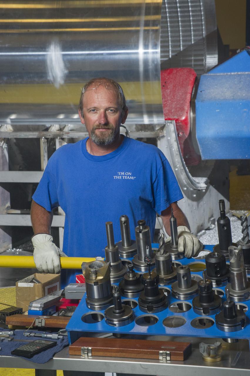
DAVID OSBORNE, A MACHINIST ON THE METTS CONTRACT, OPERATES THE 7-AXIS MILLING MACHINE WITH CF1 BARREL BEING PREPARED FOR SHELL BUCKLE TESTING
DAVID OSBORNE, A MACHINIST ON THE METTS CONTRACT, OPERATES THE 7-AXIS MILLING MACHINE WITH CF1 BARREL BEING PREPARED FOR SHELL BUCKLE TESTING
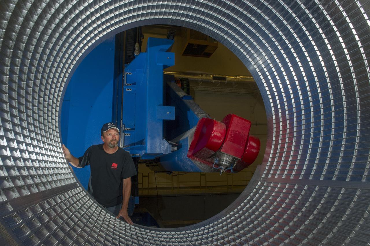
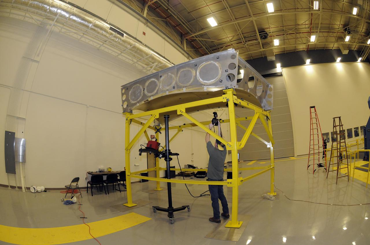
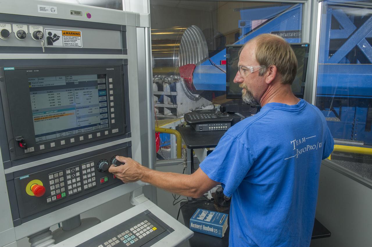
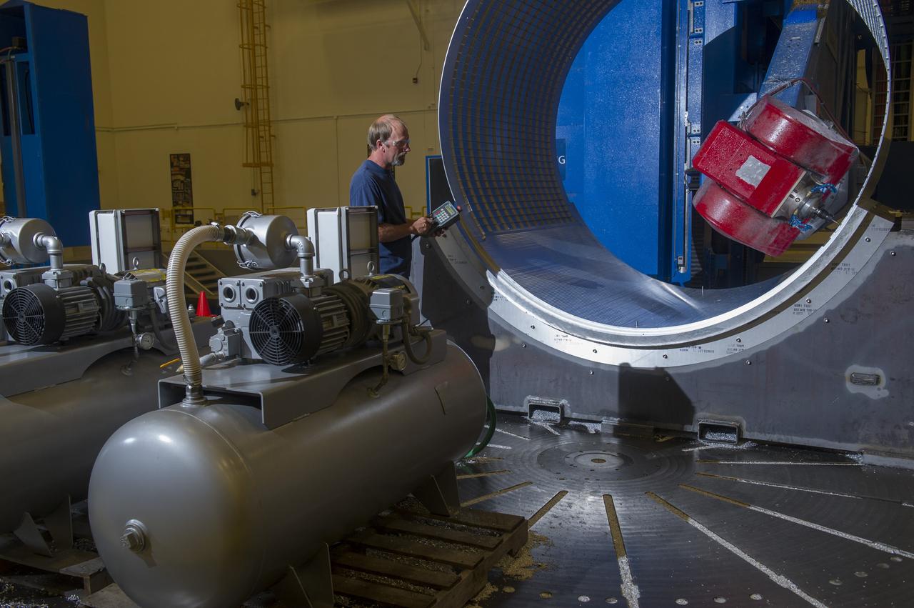
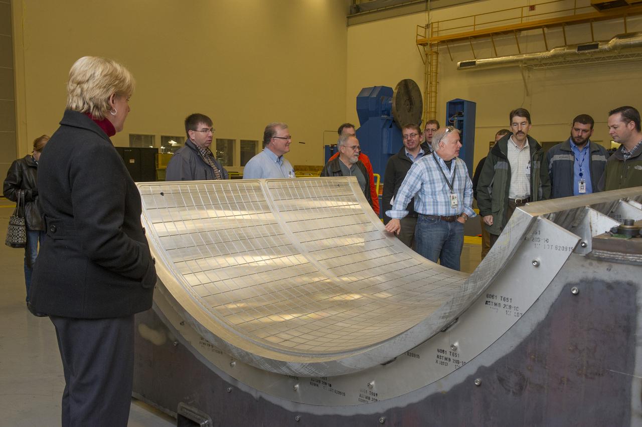
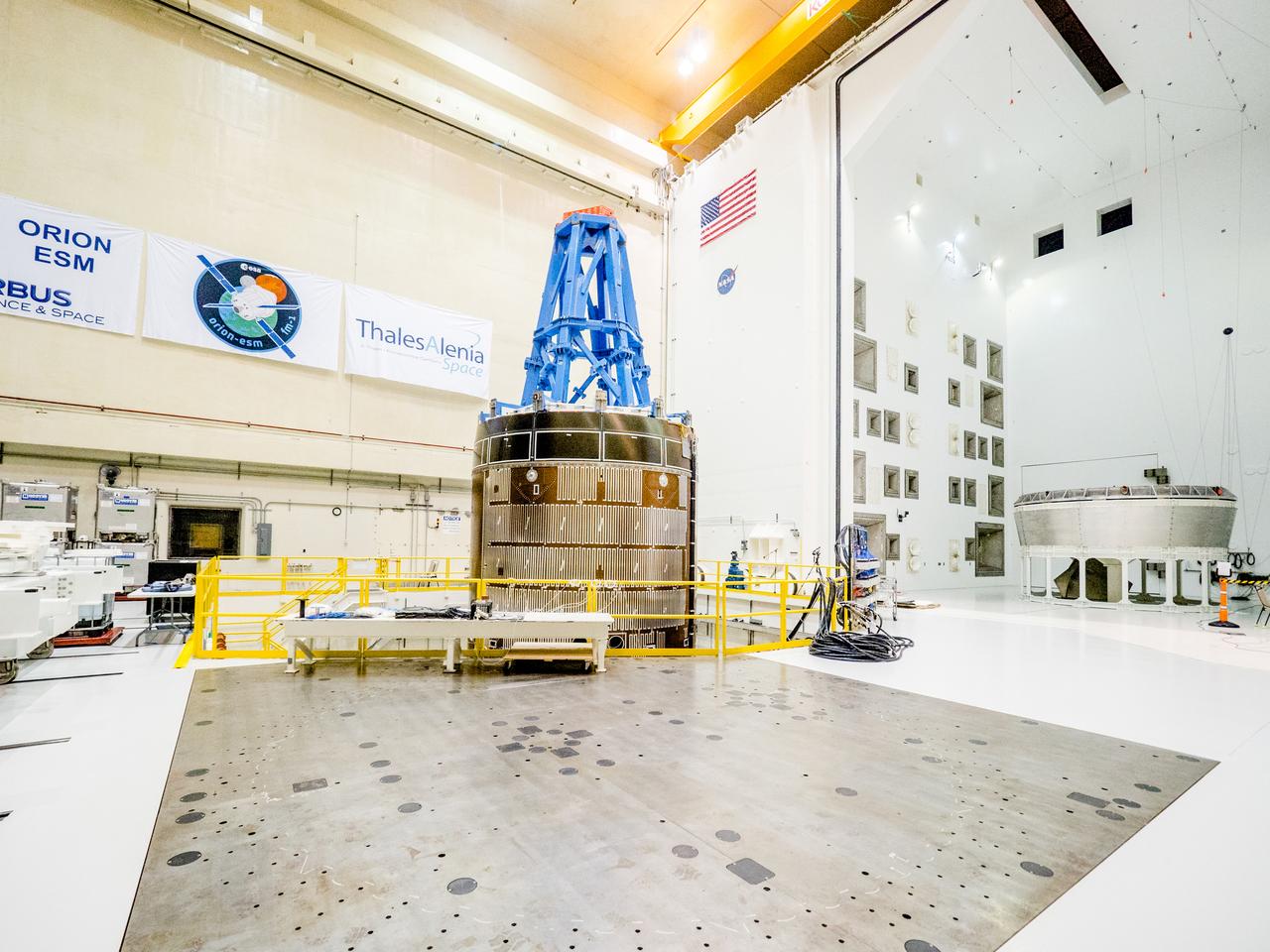
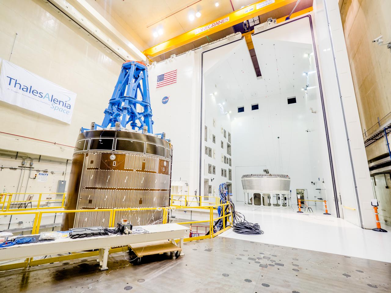
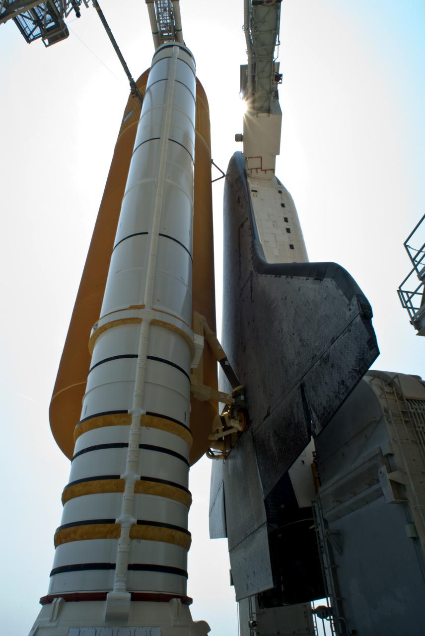
DAVID OSBORNE, A MACHINIST ON THE METTS CONTRACT, INSPECTS THE ORTHOGRID TOOL PATH ON AN 8 FOOT CF1 BARREL IN SUPPORT OF THE SHELL BUCKLING TEST FOR LANGLEY RESEARCH CENTER. THIS IS THE FIRST BARREL THAT MSFC HAS MANUFACTURED FROM EXTRUDED MATERIAL, VERSUS THE ORIGINAL DESIGN BEING 3 SECTIONS BARREL PANELS THAT WERE FRICTION STIR WELDED. THE TESTING WILL SHOW THE DIFFERENT STRENGTH PROPERTIES FROM A WELDED VERSION TO A FULLY EXTRUDED PIECE OF MATERIAL.
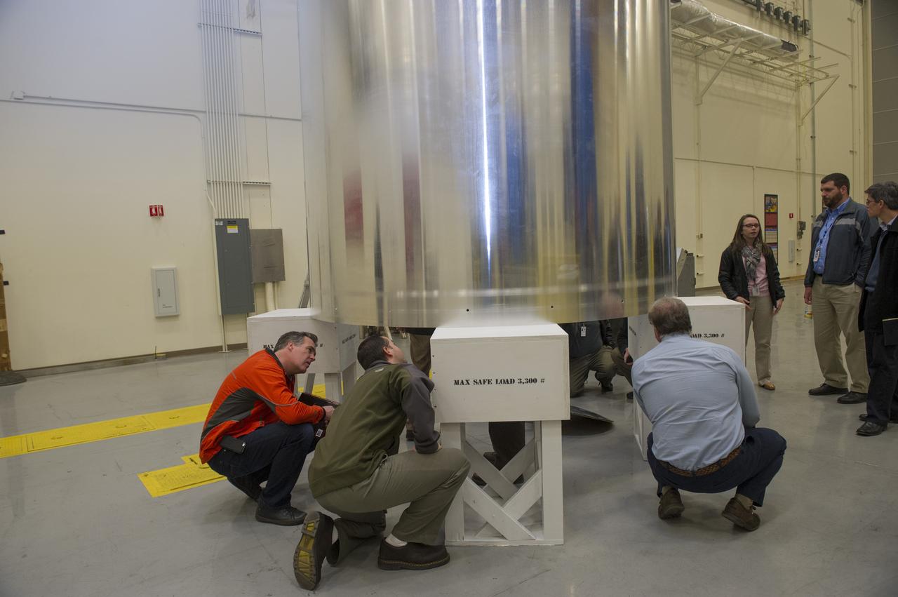
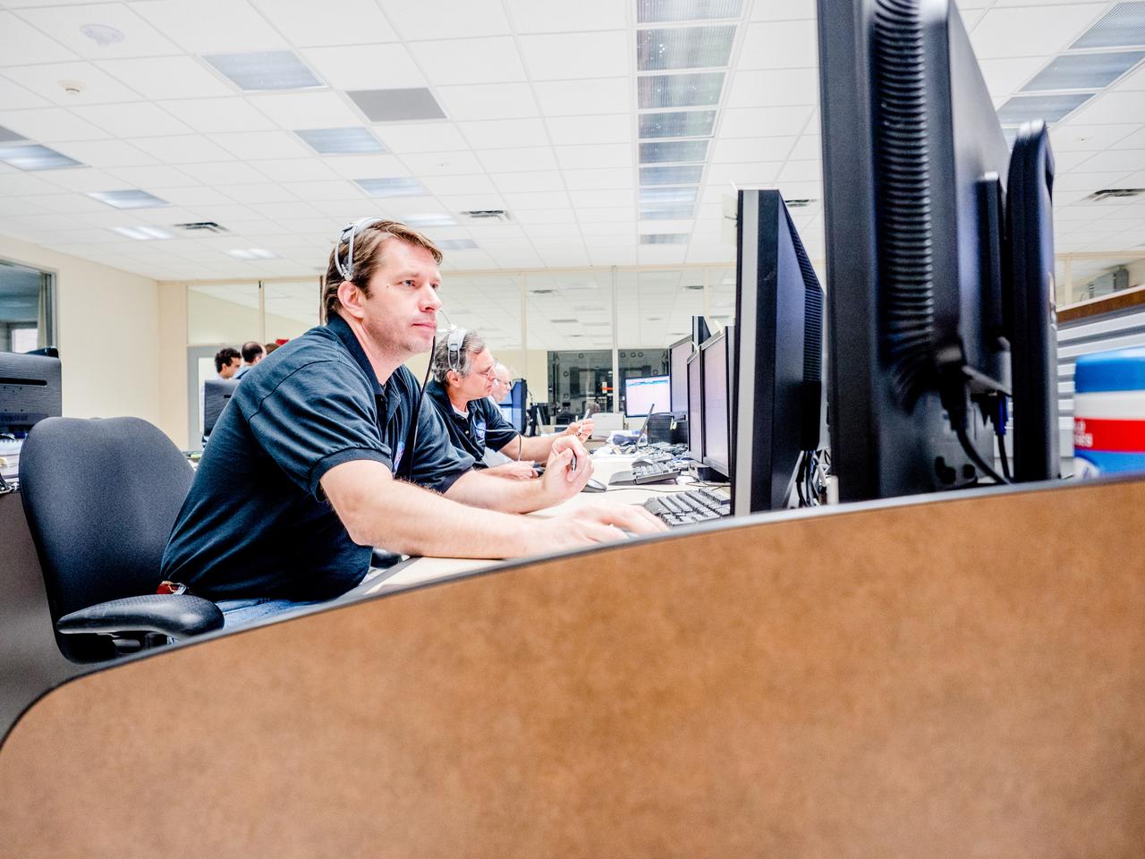
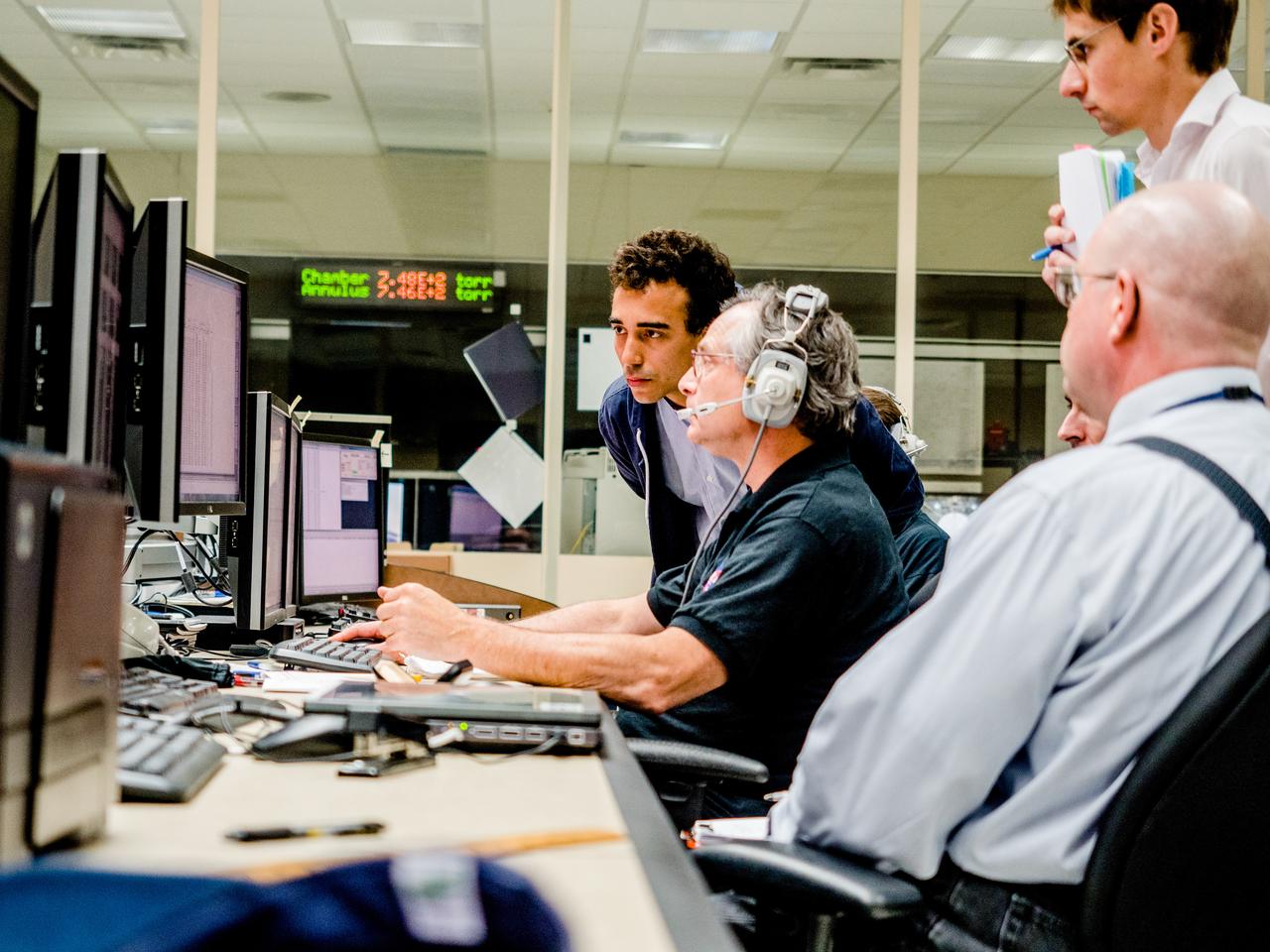
5TH SBKF (SHELL BUCKLE KNOCKDOWN FACTOR) WORKSHOP, MSFC, FEB. 3-4, 2015
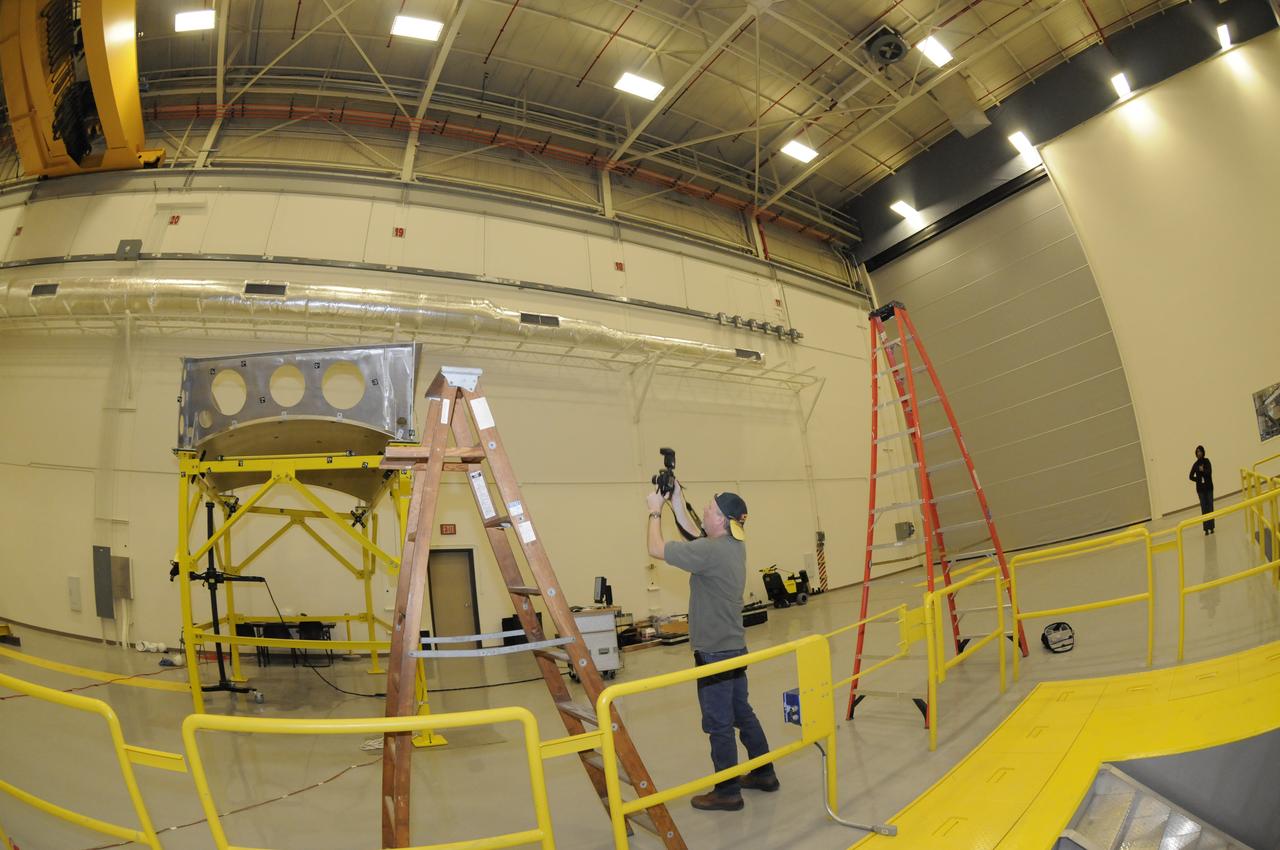
JOHN V. BAUSANO, ICRC, COMPOSITE ENGINEER, CHECKING QUARTER DOME MACHINING VERIFICATION FILM
JOHN V. BAUSANO, ICRC, COMPOSITE ENGINEER, CHECKING QUARTER DOME MACHINING VERIFICATION FILM.
JOHN V. BAUSANO, IRC, COMPOSITE ENGINEER, CHECKING QUARTER DOME MACHINING VERIFICATION FILM
5TH SBKF (SHELL BUCKLE KNOCKDOWN FACTOR) WORKSHOP, MSFC, FEB. 3-4, 2015
JOHN V. BAUSANO, ICRC, COMPOSITE ENGINEER, CHECKING QUARTER DOME MACHINING VERIFICATION FILM
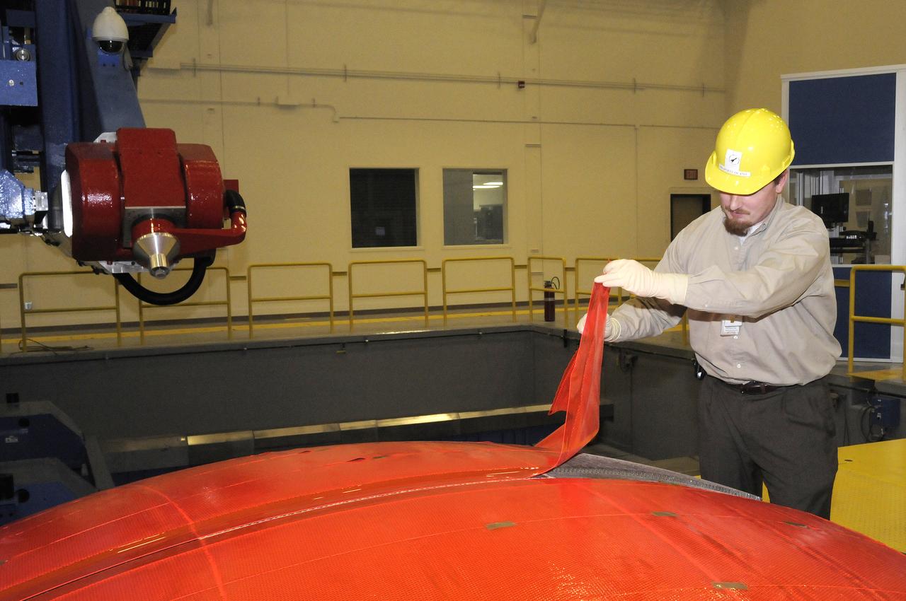
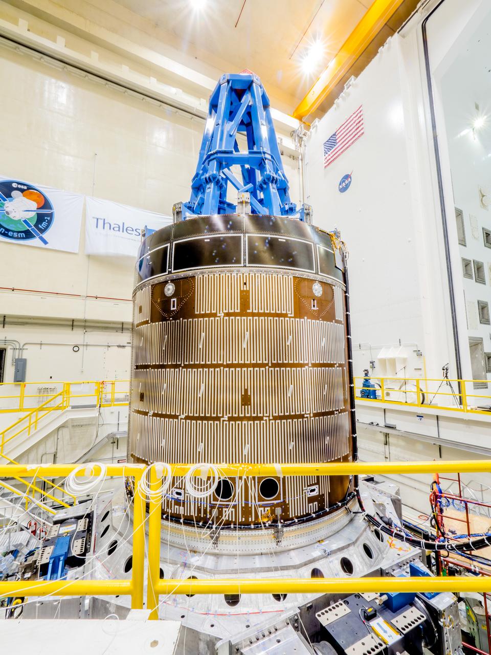
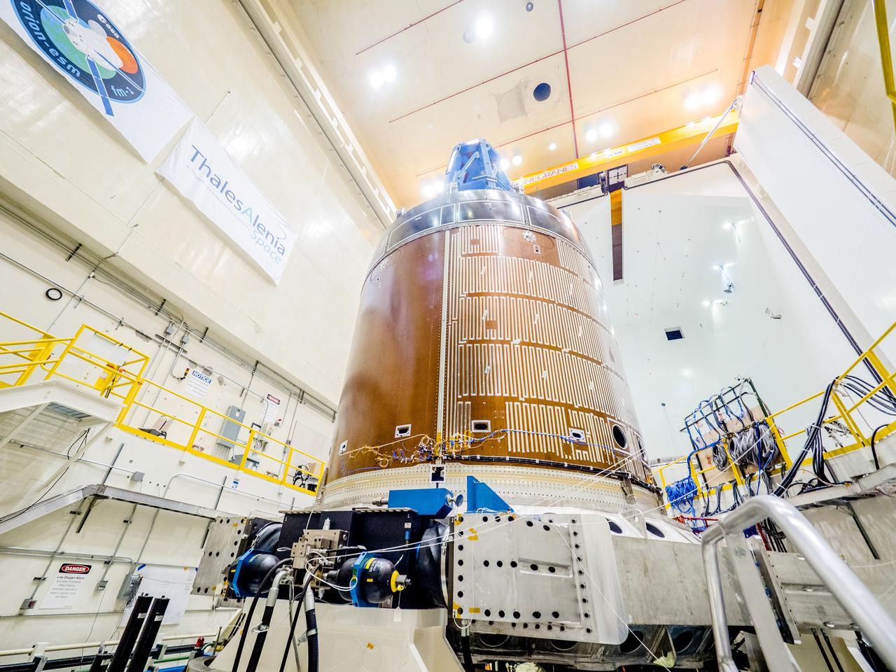
ENGINEERS FROM AMES RESEARCH CENTER AND MARSHALL SPACE FLIGHT CENTER REMOVE AVCOAT SEGMENTS FROM THE SURFACE OF THE ORION HEAT SHIELD, THE PROTECTIVE SHELL DESIGNED TO HELP THE NEXT GENERATION CREW MODULE WITHSTAND THE HEAT OF ATMOSPHERIC REENTRY. THE HEAT SHIELD FLEW TO SPACE DURING THE EFT-1 FULL SCALL FLIGHT TEST OF ORION IN DECEMBER 2014
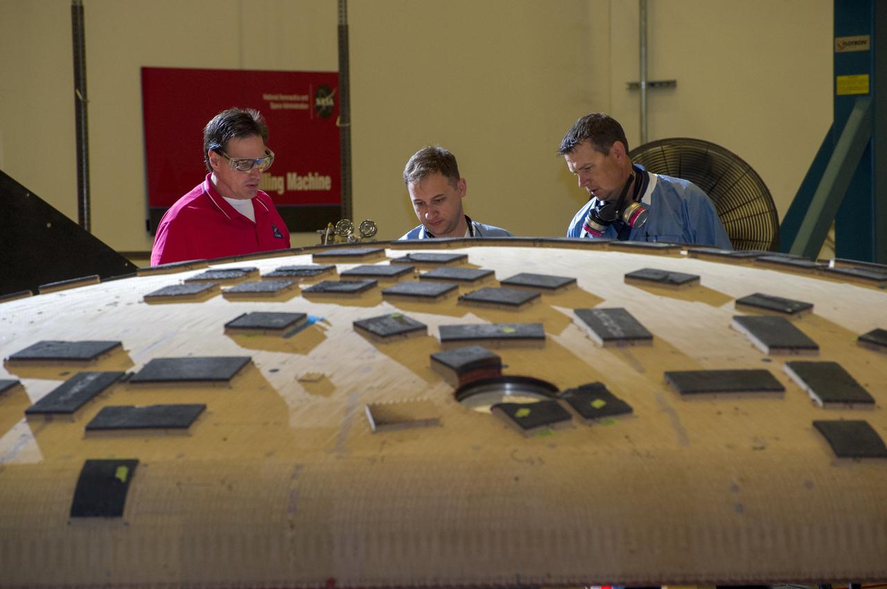
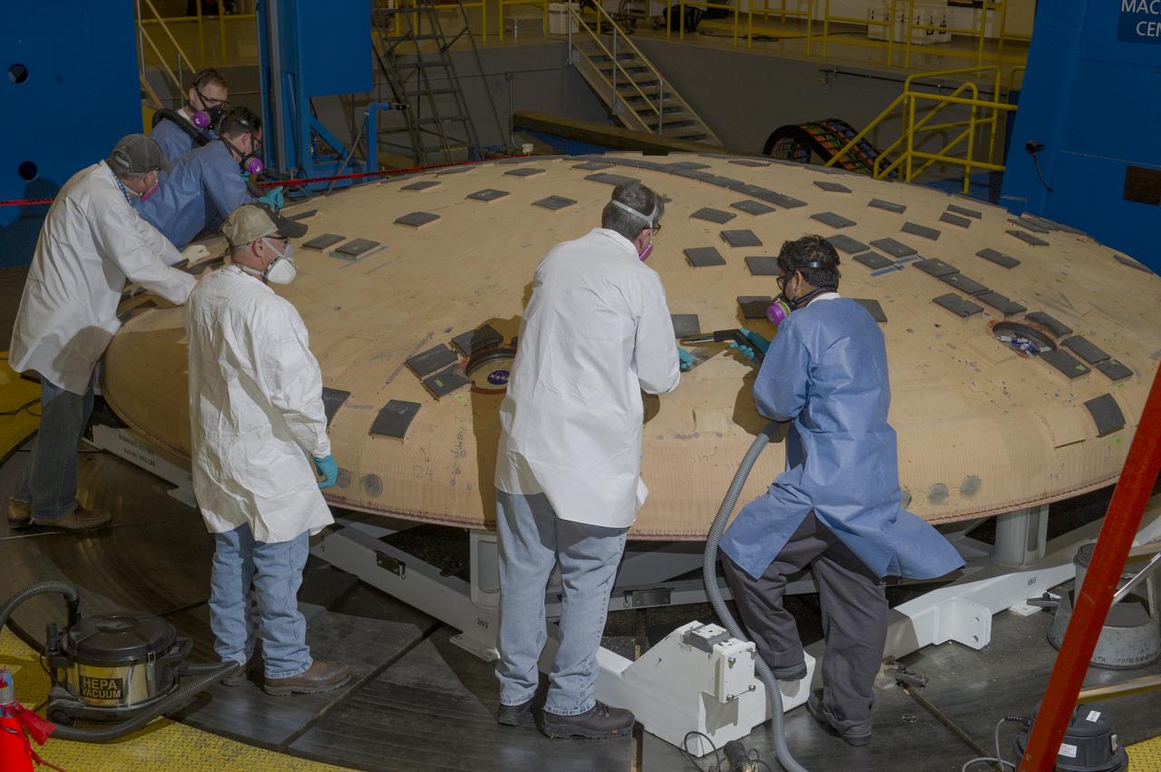
OVERSEEING ORION HEAT SHIELD WORK IN MARSHALL'S SEVEN-AXIS MILLING AND MACHINING FACILITY ARE, FROM LEFT, JOHN KOWAL, MANAGER OF ORION'S THERMAL PROTECTION SYSTEM AT JOHNSON SPACE CENTER; NICHOLAS CROWLEY, AN AMES ENGINEERING TECHNICIAN; AND ROB KORNIENKO, AMES ENGINEERING BRANCH CHIEF. THE HEAT SHIELD FLEW TO SPACE DURING THE EFT-1 FULL SCALE FLIGHT TEST OF ORION IN DECEMBER, 2014
5FTH SBKF (SHELL BUCKLE KNOCKDOWN FACTOR) WORKSHOP, MSFC, FEB. 3-4, 2015

This image of the active galaxy Centaurus A was taken by NASA's Galaxy Evolution Explorer on June 7, 2003. The galaxy is located 30 million light-years from Earth and is seen edge on, with a prominent dust lane across the major axis. In this image the near ultraviolet emission is represented as green, and the far ultraviolet emission as blue. The galaxy exhibits jets of high energy particles, which were traced by the X-ray emission and measured by NASA's Chandra X-ray Observatory. These X-ray emissions are seen as red in the image. Several regions of ultraviolet emission can be seen where the jets of high energy particles intersect with hydrogen clouds in the upper left corner of the image. The emission shown may be the result of recent star formation triggered by the compression of gas by the jet. http://photojournal.jpl.nasa.gov/catalog/PIA04624
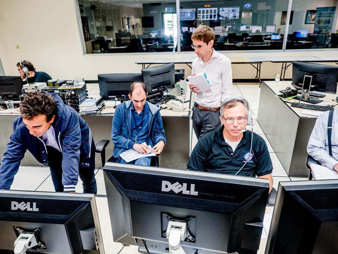
A successful test is completed of the European Structural Test Article (E-STA) partial tank vibration test (Y- axis at 80% power) performed on the Mechanical Vibration Facility (MVF) table at NASA Glenn’s Space Power Facility at Plum Brook Station, Sandusky, Ohio on Sept. 7, 2016 .Part of Batch images transfer from Flickr.
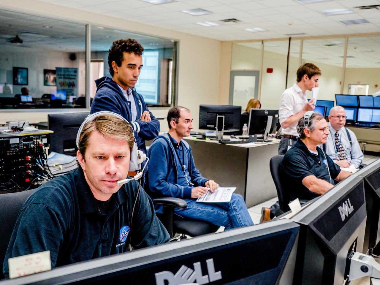
A successful test is completed of the European Structural Test Article (E-STA) partial tank vibration test (Y- axis at 80% power) performed on the Mechanical Vibration Facility (MVF) table at NASA Glenn’s Space Power Facility at Plum Brook Station, Sandusky, Ohio on Sept. 7, 2016 .Part of Batch images transfer from Flickr.
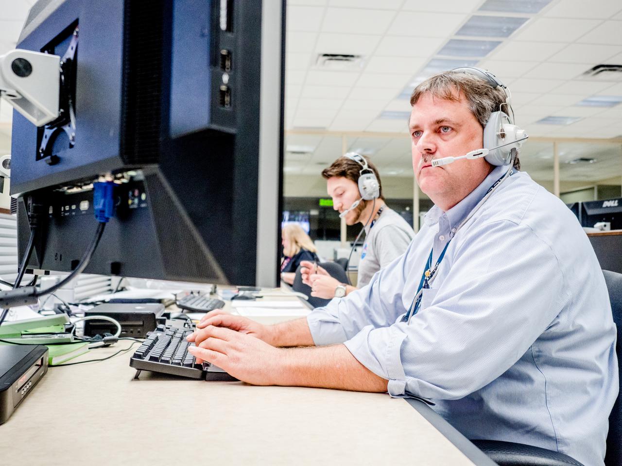
A successful test is completed of the European Structural Test Article (E-STA) partial tank vibration test (Y- axis at 80% power) performed on the Mechanical Vibration Facility (MVF) table at NASA Glenn’s Space Power Facility at Plum Brook Station, Sandusky, Ohio on Sept. 7, 2016 . Part of Batch images transfer from Flickr.
A successful test is completed of the European Structural Test Article (E-STA) partial tank vibration test (Y- axis at 80% power) performed on the Mechanical Vibration Facility (MVF) table at NASA Glenn’s Space Power Facility at Plum Brook Station, Sandusky, Ohio on Sept. 7, 2016 .Part of Batch images transfer from Flickr.
A successful test is completed of the European Structural Test Article (E-STA) partial tank vibration test (Y- axis at 80% power) performed on the Mechanical Vibration Facility (MVF) table at NASA Glenn’s Space Power Facility at Plum Brook Station, Sandusky, Ohio on Sept. 7, 2016 .Part of Batch images transfer from Flickr.
A successful test is completed of the European Structural Test Article (E-STA) partial tank vibration test (Y- axis at 80% power) performed on the Mechanical Vibration Facility (MVF) table at NASA Glenn’s Space Power Facility at Plum Brook Station, Sandusky, Ohio on Sept. 7, 2016 . Part of Batch images transfer from Flickr.
A successful test is completed of the European Structural Test Article (E-STA) partial tank vibration test (Y- axis at 80% power) performed on the Mechanical Vibration Facility (MVF) table at NASA Glenn’s Space Power Facility at Plum Brook Station, Sandusky, Ohio on Sept. 7, 2016 . Part of Batch images transfer from Flickr.
A successful test is completed of the European Structural Test Article (E-STA) partial tank vibration test (Y- axis at 80% power) performed on the Mechanical Vibration Facility (MVF) table at NASA Glenn’s Space Power Facility at Plum Brook Station, Sandusky, Ohio on Sept. 7, 2016 . Part of Batch images transfer from Flickr.
A successful test is completed of the European Structural Test Article (E-STA) partial tank vibration test (Y- axis at 80% power) performed on the Mechanical Vibration Facility (MVF) table at NASA Glenn’s Space Power Facility at Plum Brook Station, Sandusky, Ohio on Sept. 7, 2016 . Part of Batch images transfer from Flickr.
A successful test is completed of the European Structural Test Article (E-STA) partial tank vibration test (Y- axis at 80% power) performed on the Mechanical Vibration Facility (MVF) table at NASA Glenn’s Space Power Facility at Plum Brook Station, Sandusky, Ohio on Sept. 7, 2016 . Part of Batch images transfer from Flickr.
A successful test is completed of the European Structural Test Article (E-STA) partial tank vibration test (Y- axis at 80% power) performed on the Mechanical Vibration Facility (MVF) table at NASA Glenn’s Space Power Facility at Plum Brook Station, Sandusky, Ohio on Sept. 7, 2016 .Part of Batch images transfer from Flickr.
S90-36708 (7 May 1990) --- STS-35 Astronomy Laboratory 1 (ASTRO-1) view shows its telescopes, instrument pointing system (IPS), and support equipment installed in Columbia's, Orbiter Vehicle (OV) 102's, payload bay (PLB) at the Kennedy Space Center (KSC) Orbiter Processing Facility (OPF). In the foreground is the Spacelab Pallet System (SPS) igloo. The stowed IPS with its three ultraviolet telescopes appears in the center of the picture. In the background, the Broad Band X Ray Telescope (BBXRT) two axis pointing system (TAPS) is barely visible. View provided by KSC with alternate number KSC-90PC-423.

Mercury astronaut John Glenn prepares for a test in the Multi-Axis Space Test Inertia Facility (MASTIF) inside the Altitude Wind Tunnel at the National Aeronautics and Space Administration (NASA) Lewis Research Center. The MASTIF was a three-axis test rig with a pilot’s chair mounted in the center. The device was designed to train Project Mercury pilots to bring a spinning spacecraft under control. An astronaut was secured in a foam couch in the center of the rig. The rig was then spun on three axes from 2 to 50 rotations per minute. Small nitrogen gas thrusters were used by the astronauts to bring the MASTIF under control. In February and March 1960, the seven Project Mercury astronauts traveled to Cleveland to train on the MASTIF. Warren North and a team of air force physicians were on hand to monitor their health. After being briefed by Lewis pilot Joe Algranti and researcher James Useller, the rider would climb into the rig and be secured in the chair, as seen in this photograph. A Lewis engineer would then slowly set the MASTIF in motion. It was the astronaut’s job to bring it under control. Each individual was required to accumulate 4.5 to 5 hours of MASTIF time. Glenn became the first American to orbit the earth on February 20, 1962 in the Friendship 7 Mercury capsule. In March 1999, the Lewis Research Center was renamed the John H. Glenn Research Center at Lewis Field.
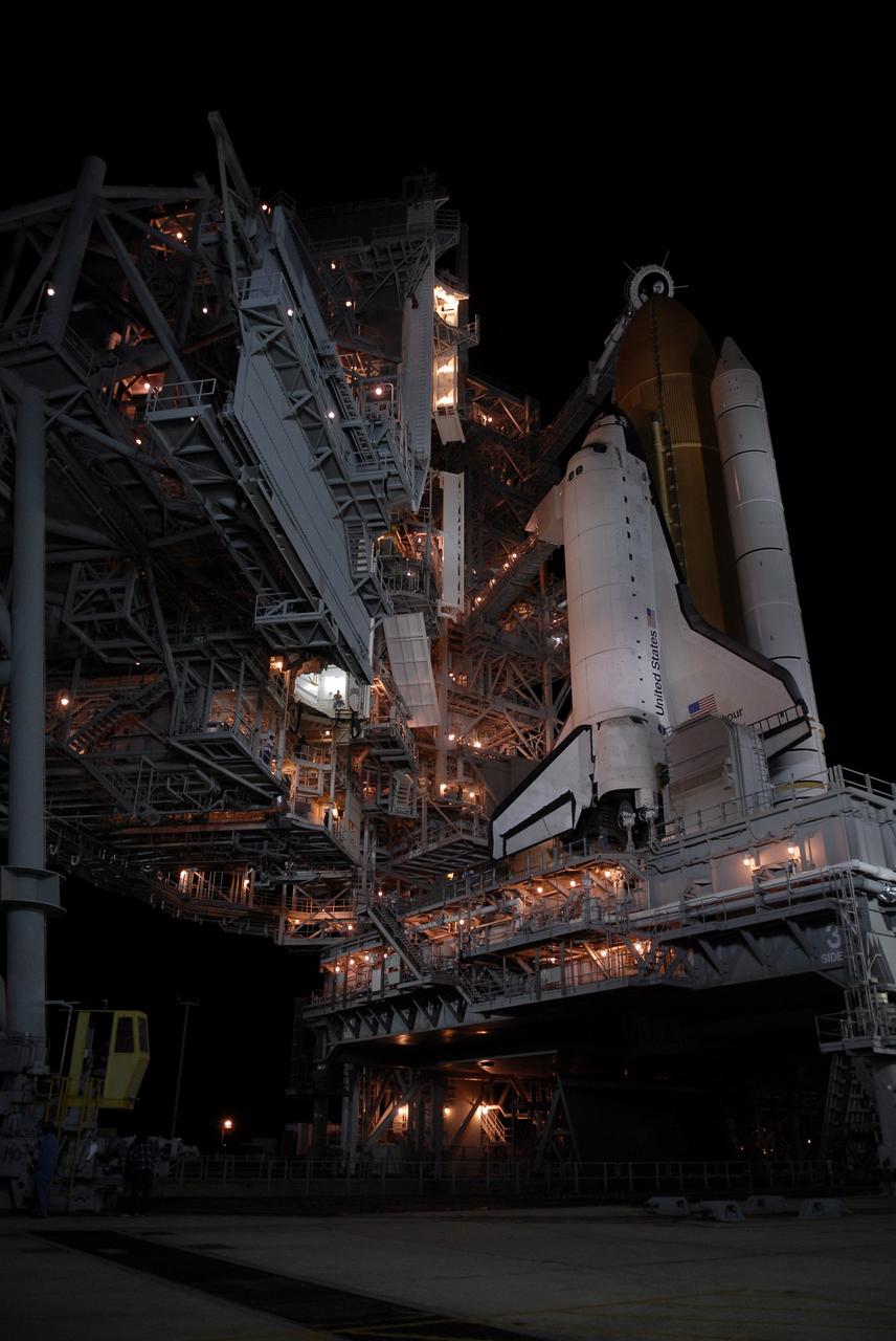
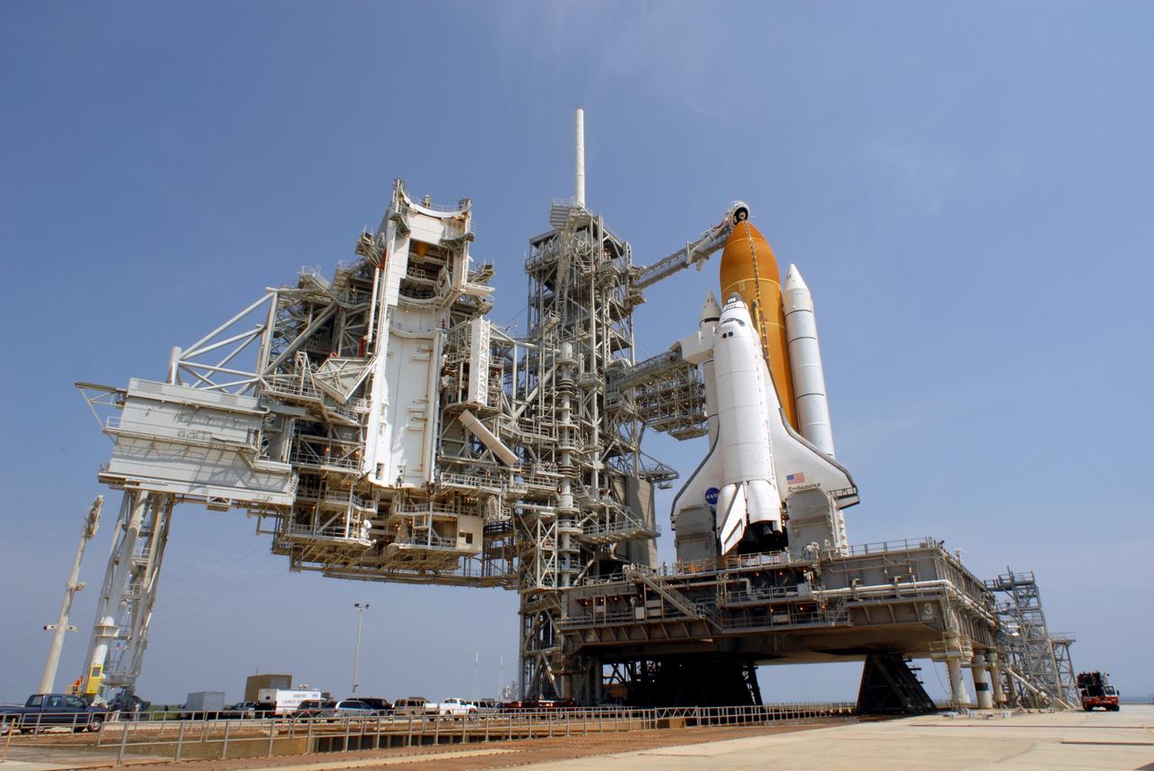
CAPE CANAVERAL, Fla. – On Launch Pad 39A at NASA's Kennedy Space Center in Florida, the orbiter access arm and White Room are extended toward space shuttle Endeavour after rollback of the rotating service structure. The rotating structure provides protected access to the shuttle for changeout and servicing of payloads at the pad. It is supported by a rotating bridge that pivots on a vertical axis on the west side of the pad's flame trench. After the RSS is rolled back, the orbiter is ready for fuel cell activation and external tank cryogenic propellant loading operations. The STS-126 mission will be the 124th space shuttle flight and the 27th flight to the International Space Station. The mission will feature four spacewalks and work that will prepare the space station to house six crew members for long- duration missions. Liftoff is scheduled for 7:55 p.m. EST Nov. 14. Photo credit: NASA/Kim Shiflett
CAPE CANAVERAL, Fla. – On Launch Pad 39A at NASA's Kennedy Space Center in Florida, the orbiter access arm and White Room are extended toward space shuttle Endeavour after rollback of the rotating service structure. The rotating structure provides protected access to the shuttle for changeout and servicing of payloads at the pad. It is supported by a rotating bridge that pivots on a vertical axis on the west side of the pad's flame trench. After the RSS is rolled back, the orbiter is ready for fuel cell activation and external tank cryogenic propellant loading operations. The STS-126 mission will be the 124th space shuttle flight and the 27th flight to the International Space Station. The mission will feature four spacewalks and work that will prepare the space station to house six crew members for long- duration missions. Liftoff is scheduled for 7:55 p.m. EST Nov. 14. Photo credit: NASA/Kim Shiflett
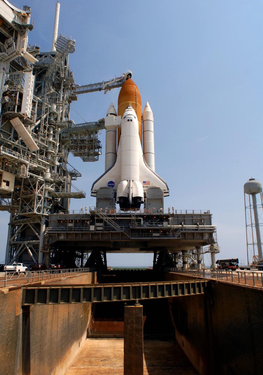
CAPE CANAVERAL, Fla. – On Launch Pad 39A at NASA's Kennedy Space Center in Florida, space shuttle Endeavour is revealed after the rotating service structure begins to roll away. The rollback is in preparation for Endeavour's liftoff on the STS-126 mission with a crew of seven. The rotating structure provides protected access to the shuttle for changeout and servicing of payloads at the pad. It is supported by a rotating bridge that pivots on a vertical axis on the west side of the pad's flame trench. After the RSS is rolled back, the orbiter is ready for fuel cell activation and external tank cryogenic propellant loading operations. The STS-126 mission will be the 124th space shuttle flight and the 27th flight to the International Space Station. The mission will feature four spacewalks and work that will prepare the space station to house six crew members for long- duration missions. Liftoff is scheduled for 7:55 p.m. EST Nov. 14. Photo credit: NASA/Kim Shiflett
CAPE CANAVERAL, Fla. – On Launch Pad 39A at NASA's Kennedy Space Center in Florida, the orbiter access arm and White Room are extended toward space shuttle Endeavour after rollback of the rotating service structure. The rotating structure provides protected access to the shuttle for changeout and servicing of payloads at the pad. It is supported by a rotating bridge that pivots on a vertical axis on the west side of the pad's flame trench. After the RSS is rolled back, the orbiter is ready for fuel cell activation and external tank cryogenic propellant loading operations. The STS-126 mission will be the 124th space shuttle flight and the 27th flight to the International Space Station. The mission will feature four spacewalks and work that will prepare the space station to house six crew members for long- duration missions. Liftoff is scheduled for 7:55 p.m. EST Nov. 14. Photo credit: NASA/Kim Shiflett
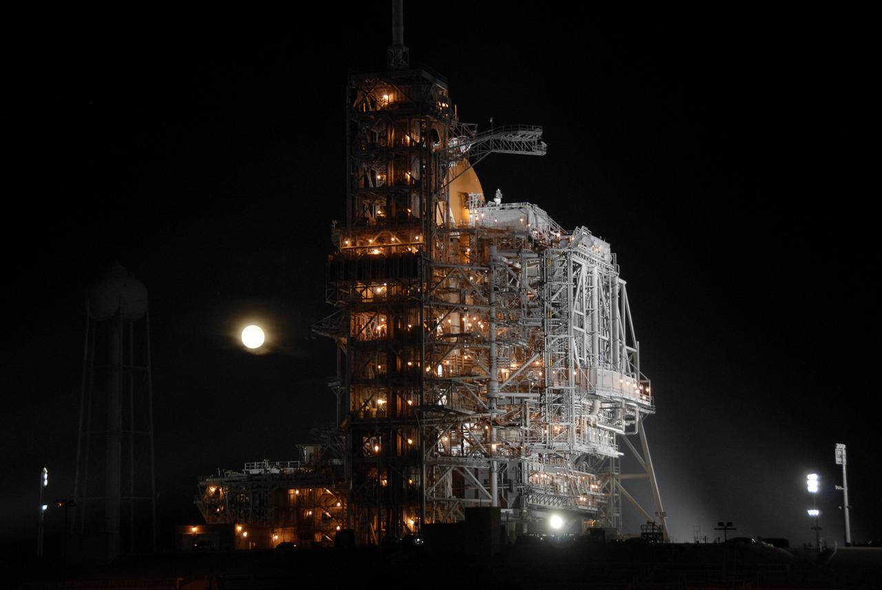
CAPE CANAVERAL, Fla. – With a full moon silhouetted in the night sky, the rotating service structure is ready to be rolled from around space shuttle Endeavour into park position on Launch Pad 39A at NASA's Kennedy Space Center in Florida. The rollback is in preparation for Endeavour's liftoff on the STS-126 mission with a crew of seven. The rotating structure provides protected access to the shuttle for changeout and servicing of payloads at the pad. It is supported by a rotating bridge that pivots on a vertical axis on the west side of the pad's flame trench. After the RSS is rolled back, the orbiter is ready for fuel cell activation and external tank cryogenic propellant loading operations. The STS-126 mission will be the 124th space shuttle flight and the 27th flight to the International Space Station. The mission will feature four spacewalks and work that will prepare the space station to house six crew members for long- duration missions. Liftoff is scheduled for 7:55 p.m. EST Nov. 14. Photo credit: NASA/Kim Shiflett
CAPE CANAVERAL, Fla. – On Launch Pad 39A at NASA's Kennedy Space Center in Florida, technicians in the control booth get ready to roll the rotating service structure, or RSS, above them away from space shuttle Endeavour. First motion was at 10:39 a.m. EDT. The rollback is in preparation for Endeavour's liftoff June 13 on the STS-127 mission with a crew of seven. The rotating structure provides protected access to the shuttle for changeout and servicing of payloads at the pad. It is supported by a rotating bridge that pivots on a vertical axis on the west side of the pad's flame trench. After the RSS is rolled back, the orbiter is ready for fuel cell activation and external tank cryogenic propellant loading operations. The launch will be Endeavour's 23rd flight. The shuttle will carry the Japanese Experiment Module's Exposed Facility, or JEM-EF, and the Experiment Logistics Module-Exposed Section, or ELM-ES, on STS-127. The mission is the final of three flights dedicated to the assembly of the Japan Aerospace Exploration Agency's Kibo laboratory complex on the space station. Endeavour's launch is scheduled for June 13 at 7:17 a.m. EDT. Photo credit: NASA/Jim Grossmann
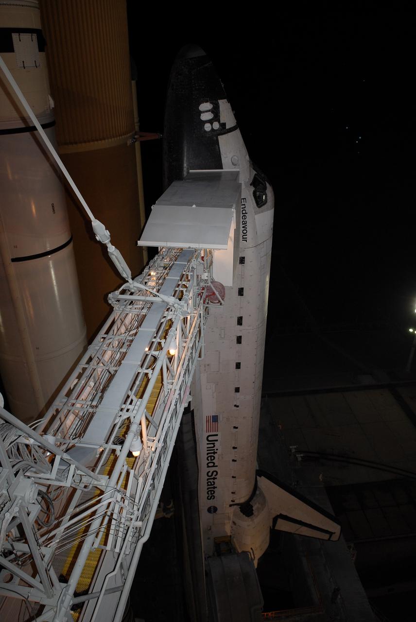
CAPE CANAVERAL, Fla. – Visible after rollback of the rotating service structure and looming like giants against the sky are the solid rocket boosters, external tank and space shuttle Endeavour, poised for launch on Launch Pad 39A at NASA's Kennedy Space Center in Florida. Near the top of Endeavour is the White Room, at the end of the orbiter access arm. The White Room provides entry into the shuttle for the astronauts. The rollback is preparation for Endeavour's liftoff June 13 on the STS-127 mission with a crew of seven. First motion was at 10:39 a.m. EDT and completed at 11:18 a.m. The rotating structure provides protected access to the shuttle for changeout and servicing of payloads at the pad. It is supported by a rotating bridge that pivots on a vertical axis on the west side of the pad's flame trench. After the RSS is rolled back, the orbiter is ready for fuel cell activation and external tank cryogenic propellant loading operations. The launch will be Endeavour's 23rd flight. The shuttle will carry the Japanese Experiment Module's Exposed Facility, or JEM-EF, and the Experiment Logistics Module-Exposed Section, or ELM-ES, on STS-127. The mission is the final of three flights dedicated to the assembly of the Japan Aerospace Exploration Agency's Kibo laboratory complex on the space station. Endeavour's launch is scheduled for June 13 at 7:17 a.m. EDT. Photo credit: NASA/Jim Grossmann
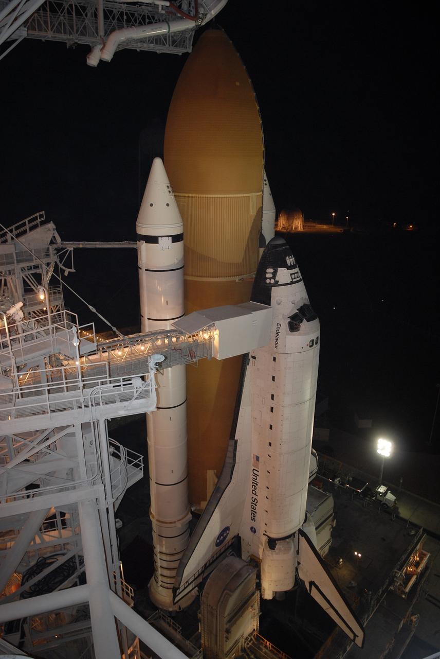
CAPE CANAVERAL, Fla. – On Launch Pad 39A at NASA's Kennedy Space Center in Florida, the oxygen vent hood, called the "beanie cap," is positioned above the external fuel tank of space shuttle Endeavour following the rollback of the rotating service structure, or RSS, at left. The beanie cap is designed to vent gaseous oxygen vapors away from the shuttle. The rollback is preparation for Endeavour's liftoff June 13 on the STS-127 mission with a crew of seven. First motion was at 10:39 a.m. EDT and completed at 11:18 a.m. The rotating structure provides protected access to the shuttle for changeout and servicing of payloads at the pad. It is supported by a rotating bridge that pivots on a vertical axis on the west side of the pad's flame trench. After the RSS is rolled back, the orbiter is ready for fuel cell activation and external tank cryogenic propellant loading operations. The launch will be Endeavour's 23rd flight. The shuttle will carry the Japanese Experiment Module's Exposed Facility, or JEM-EF, and the Experiment Logistics Module-Exposed Section, or ELM-ES, on STS-127. The mission is the final of three flights dedicated to the assembly of the Japan Aerospace Exploration Agency's Kibo laboratory complex on the space station. Endeavour's launch is scheduled for June 13 at 7:17 a.m. EDT. Photo credit: NASA/Jim Grossmann
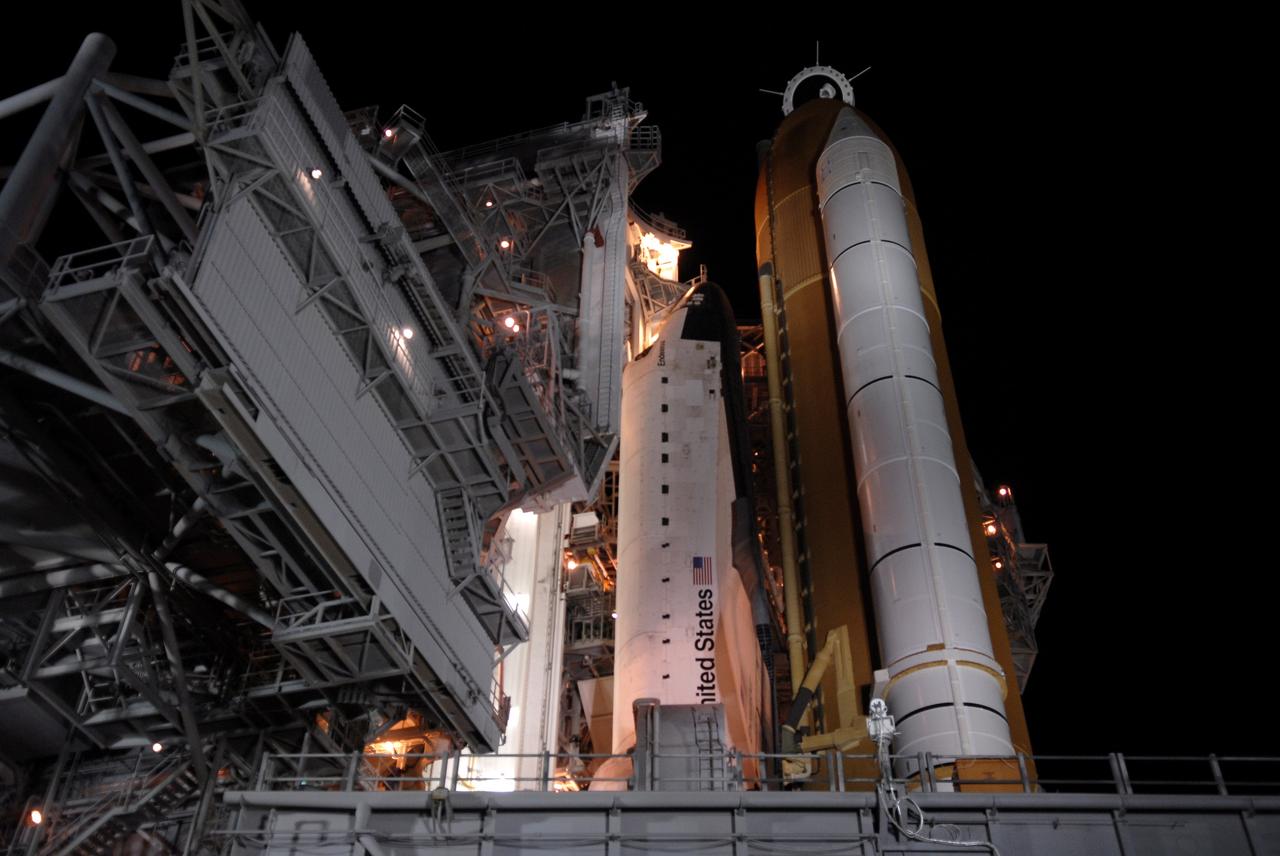
CAPE CANAVERAL, Fla. – On Launch Pad 39A at NASA's Kennedy Space Center in Florida, space shuttle Endeavour is revealed after the rollback of the rotating service structure, or RSS. In the foreground is the flame trench, which the mobile launcher platform straddles. On top of the external fuel tank is the oxygen vent hood, called the "beanie cap," which is designed to vent gaseous oxygen vapors away from the shuttle. The rollback is preparation for Endeavour's liftoff June 13 on the STS-127 mission with a crew of seven. First motion was at 10:39 a.m. EDT and completed at 11:18 a.m. The rotating structure provides protected access to the shuttle for changeout and servicing of payloads at the pad. It is supported by a rotating bridge that pivots on a vertical axis on the west side of the pad's flame trench. After the RSS is rolled back, the orbiter is ready for fuel cell activation and external tank cryogenic propellant loading operations. The launch will be Endeavour's 23rd flight. The shuttle will carry the Japanese Experiment Module's Exposed Facility, or JEM-EF, and the Experiment Logistics Module-Exposed Section, or ELM-ES, on STS-127. The mission is the final of three flights dedicated to the assembly of the Japan Aerospace Exploration Agency's Kibo laboratory complex on the space station. Endeavour's launch is scheduled for June 13 at 7:17 a.m. EDT. Photo credit: NASA/Jim Grossmann