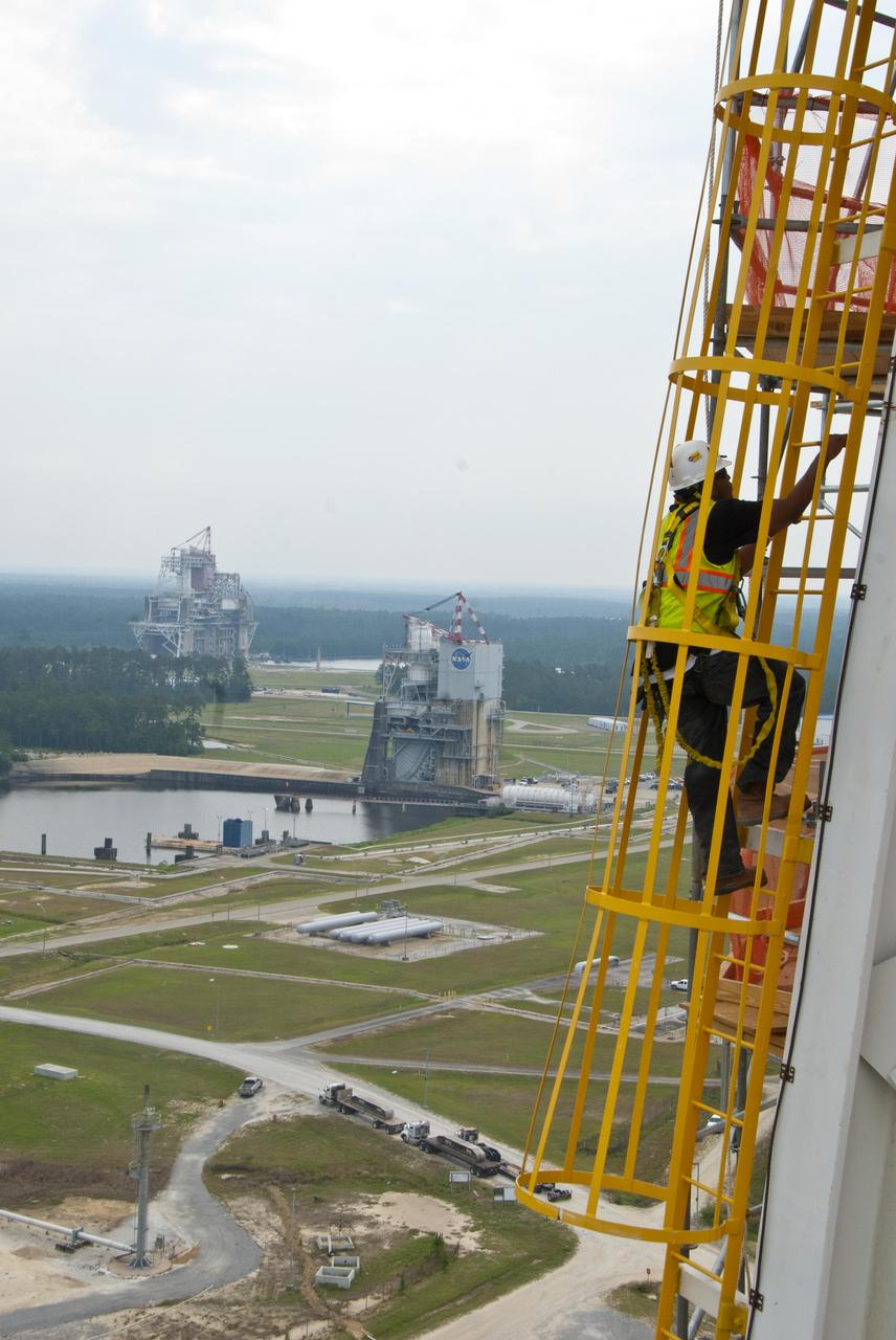
A tethered Stennis Space Center employee climbs an A-3 Test Stand ladder June 8, 2012, against the backdrop of the A-2 and B-1/B-2 stands. The new A-3 Test Stand will enable simulated high-altitude testing of next-generation rocket engines.

A tethered Stennis Space Center employee climbs an A-3 Test Stand ladded June 8, 2012, against the backdrop of the A-2 and B-1/B-2 stands. The new A-3 Test Stand will enable simulated high-altitude testing of next-generation rocket engines.

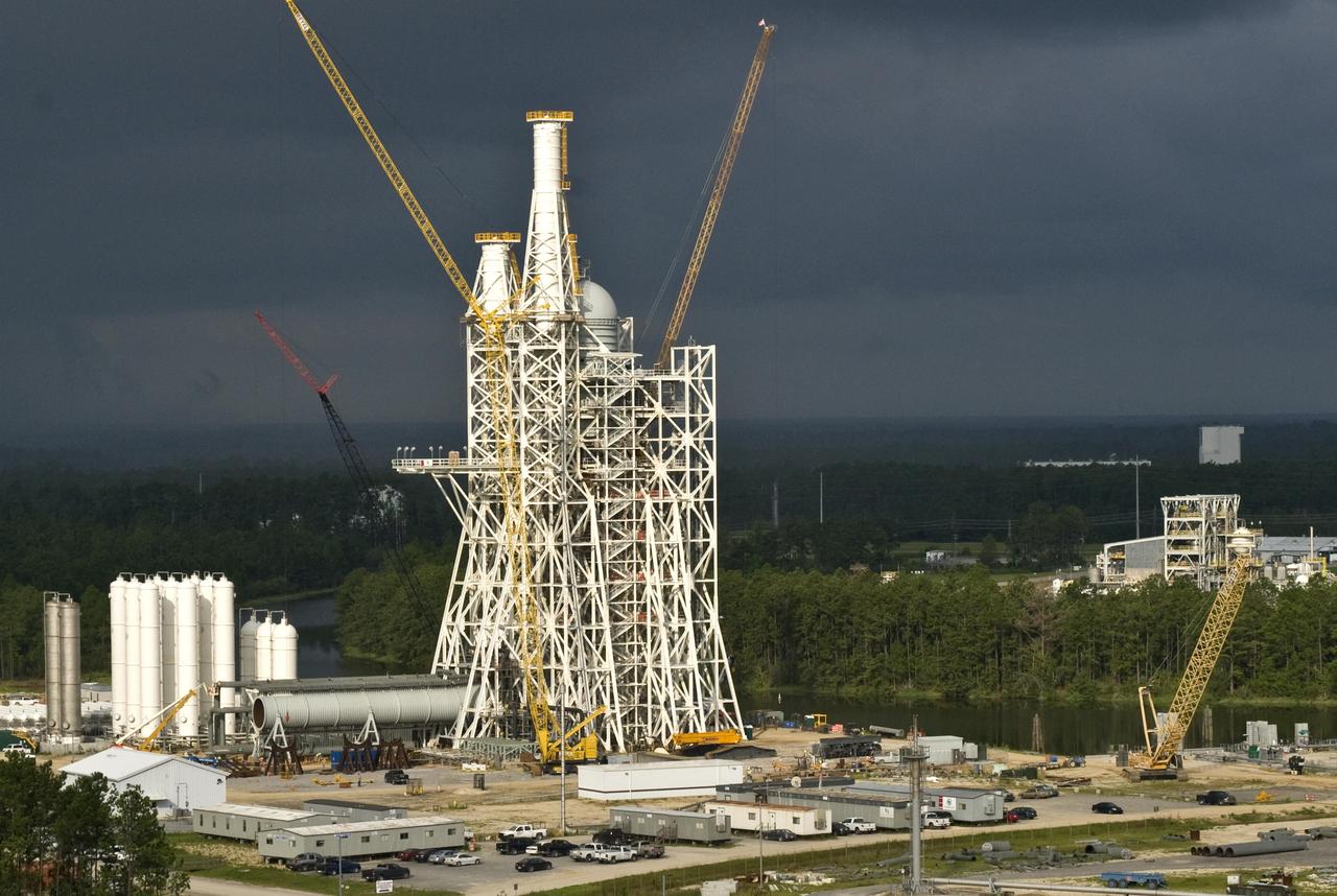
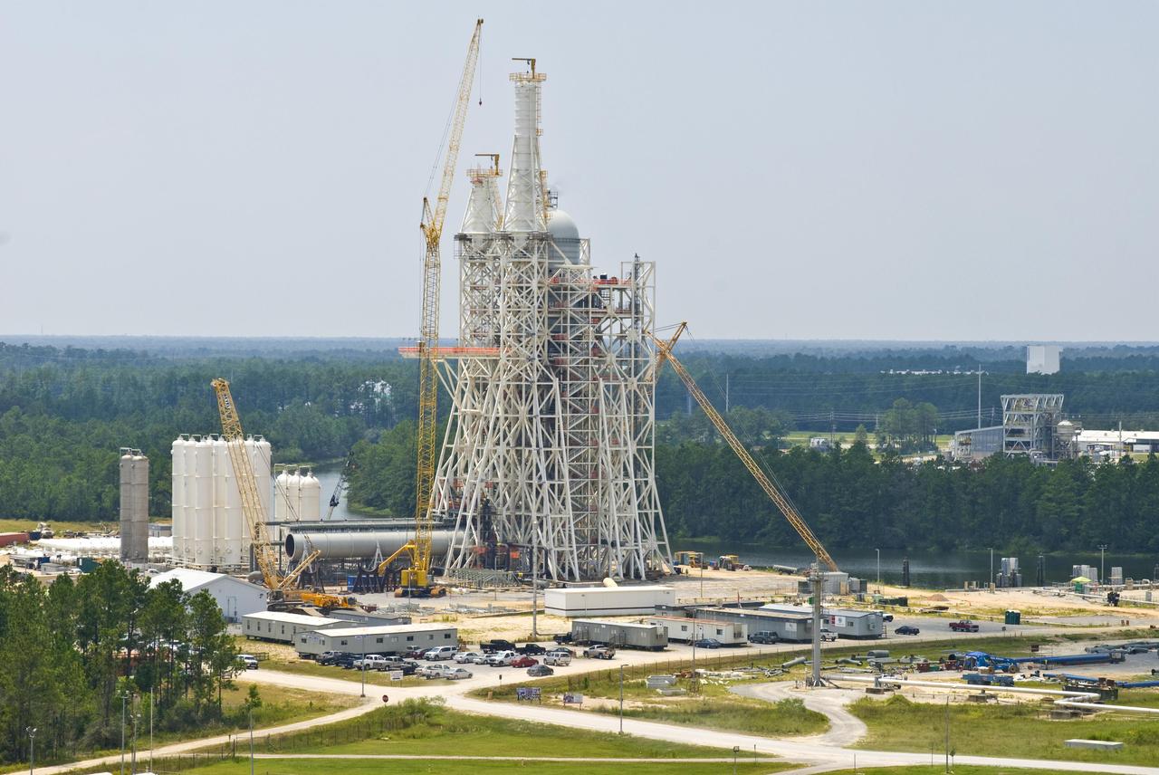
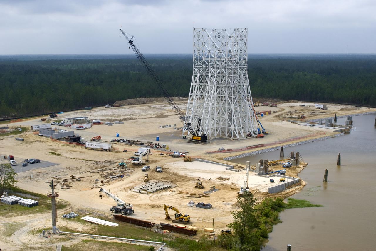
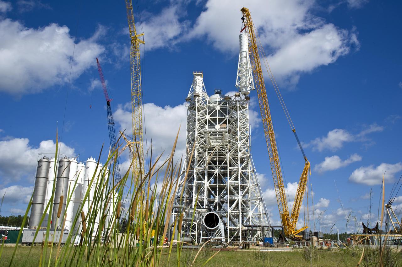
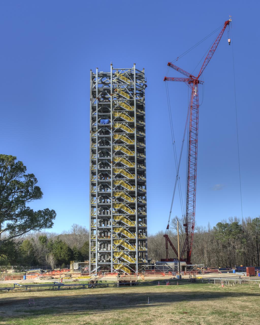
Work continues on the A-3 Test Stand at Stennis Space Center. The new stand will allow operators to test next-generation rocket engines at simulated altitudes up to 100,000 feet. The test stand is scheduled for completion and activation in 2013.
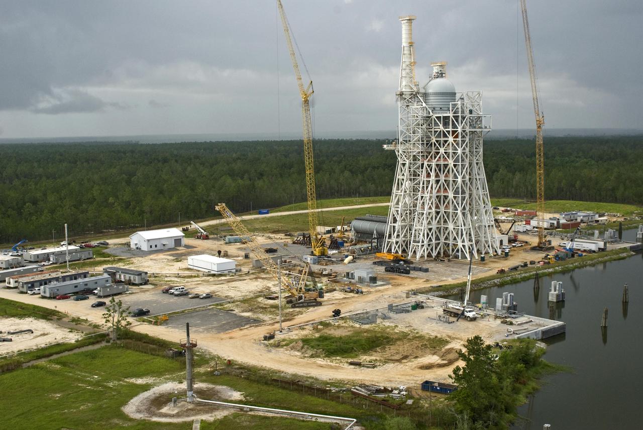
Work continues on the A-3 Test Stand at Stennis Space Center. The new stand will allow operators to test next-generation rocket engines at simulated altitudes up to 100,000 feet. The test stand is scheduled for completion and activation in 2013.
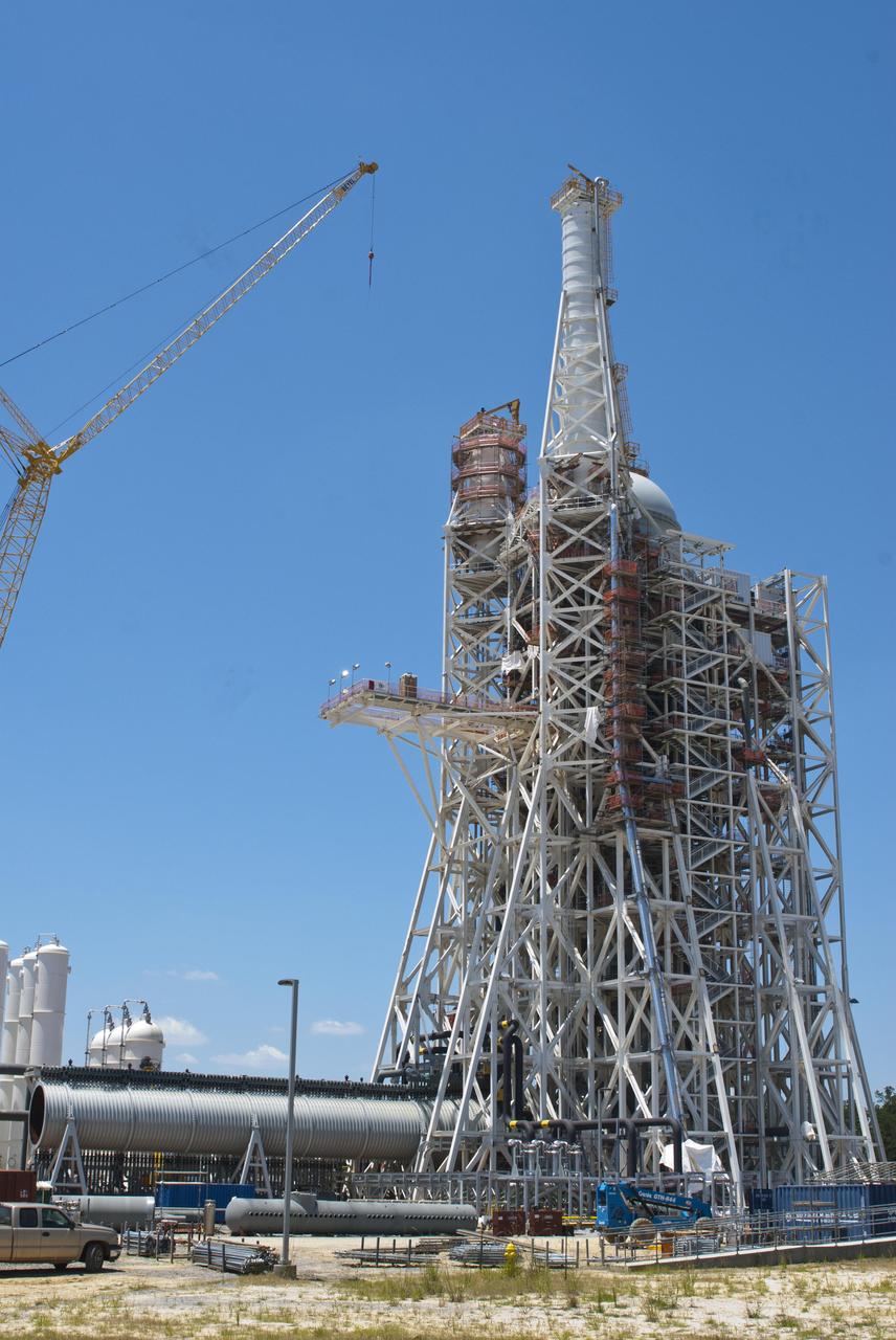
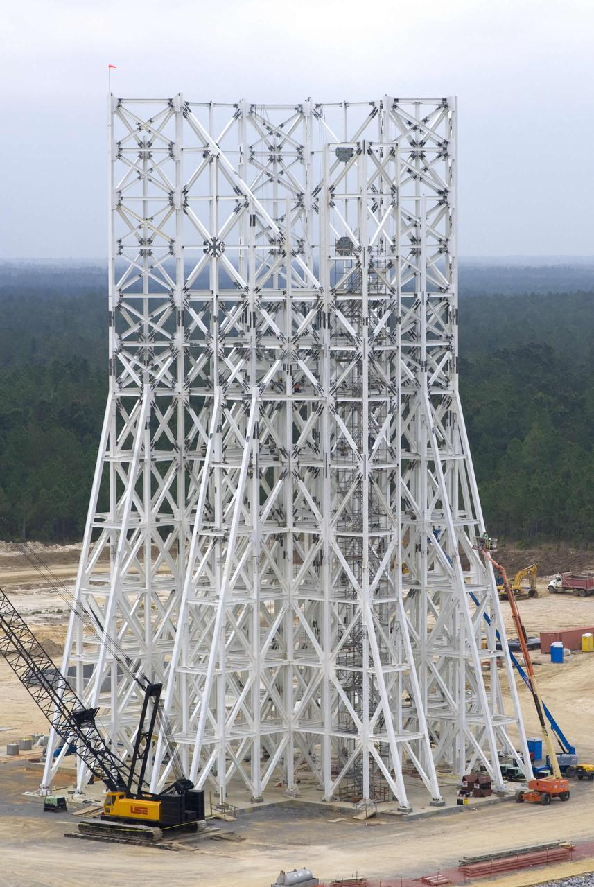
Construction continues on NASA's A-3 Test Stand at Stennis Space Center. The stand is the first large test structure built at the south Mississippi facility since the 1960s.
Construction on the new A-3 Test Stand continues at NASA's Stennis Space Center. The stand is the first large test structure built at the NASA facility since the 1960s.

Construction on the new A-3 Test Stand continues at NASA's Stennis Space Center. The stand is the first large test structure built at the NASA facility since the 1960s.
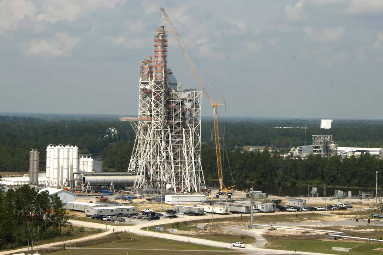
Construction of the A-3 Test Stand at Stennis Space Center continued throughout 2011. The stand is the first large test structure built at Stennis since the 1960s.

Construction of the A-3 Test Stand at Stennis Space Center continued throughout 2011. The stand is the first large test structure built at Stennis since the 1960s.
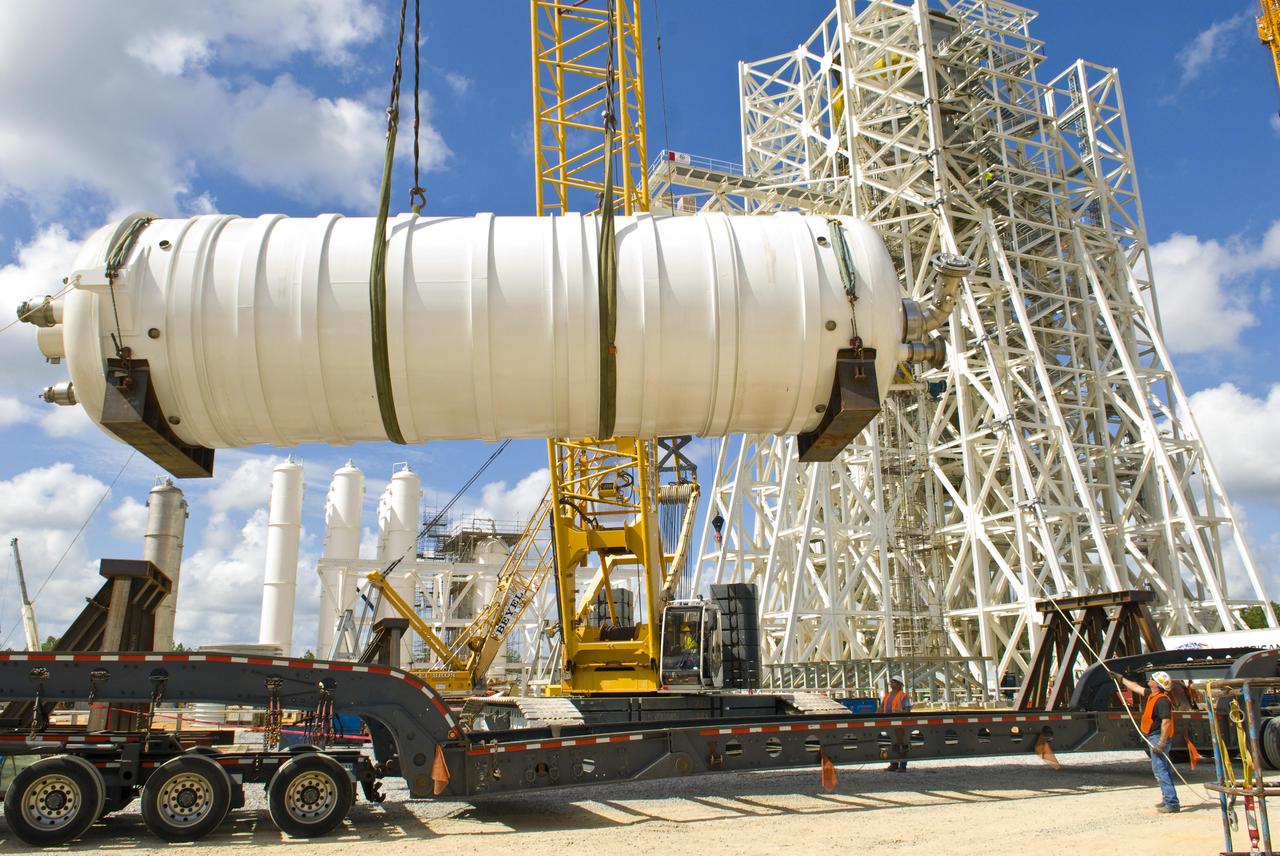
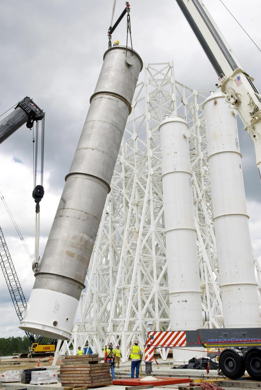
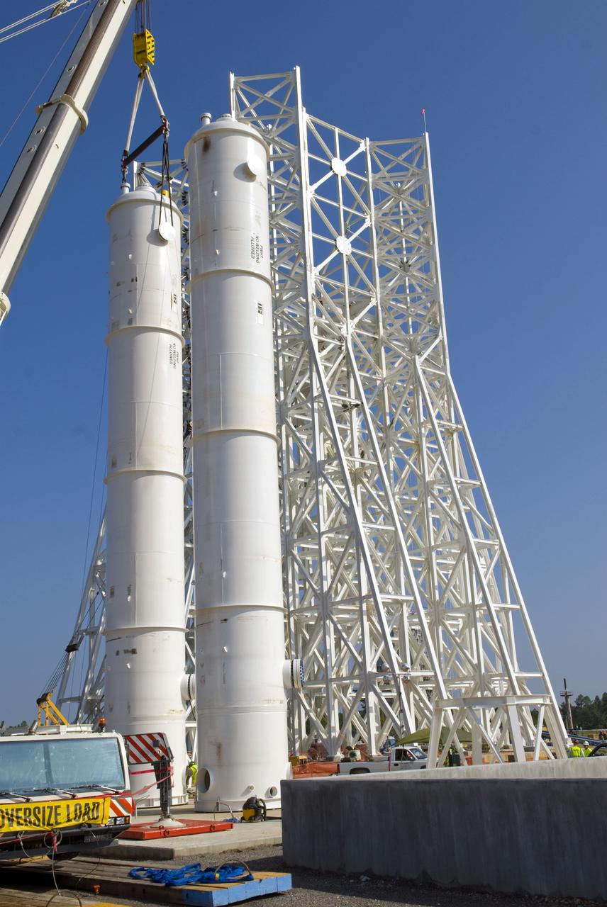
Stennis Space Center employees have installed liquid oxygen and liquid hydrogen tanks atop the A-3 Test Stand, raising the structure to its full 300-foot height. The stand is being built to test next-generation rocket engines that could carry humans beyond low-Earth orbit into deep space. The A-3 Test Stand is scheduled for completion and activation in 2013.
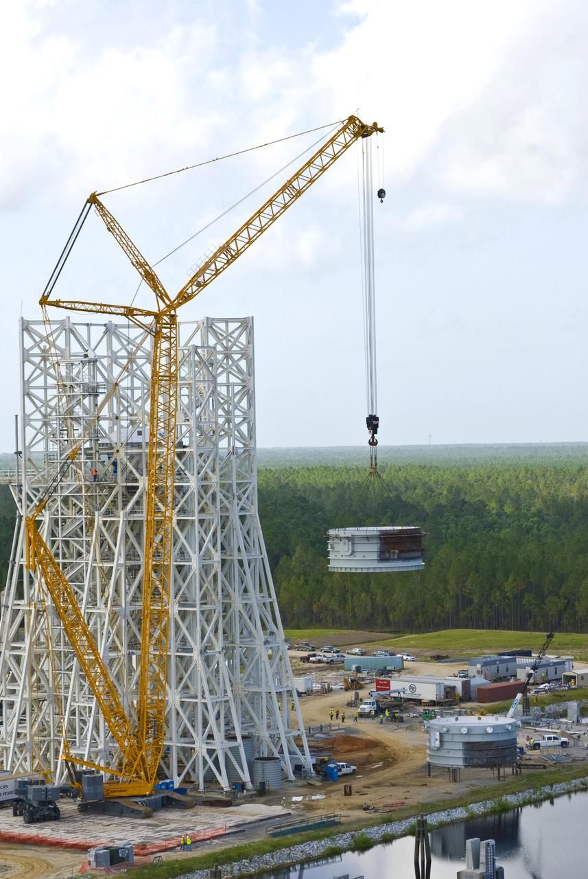
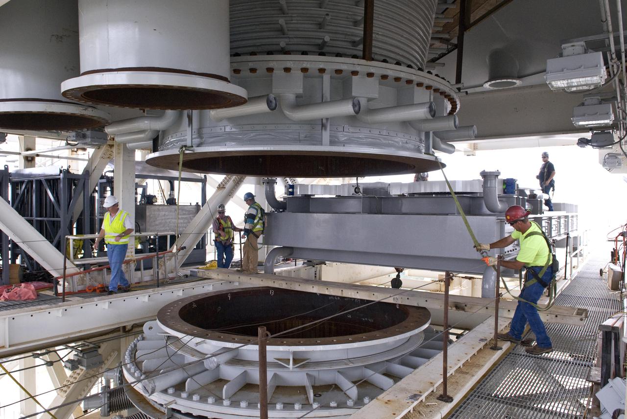
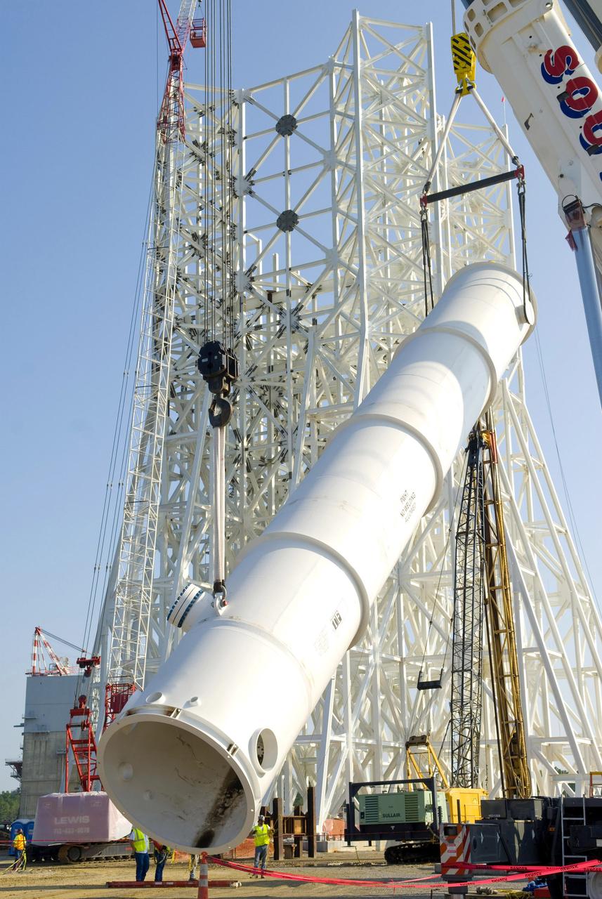
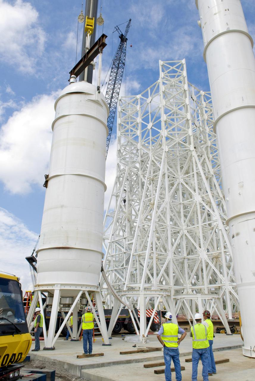
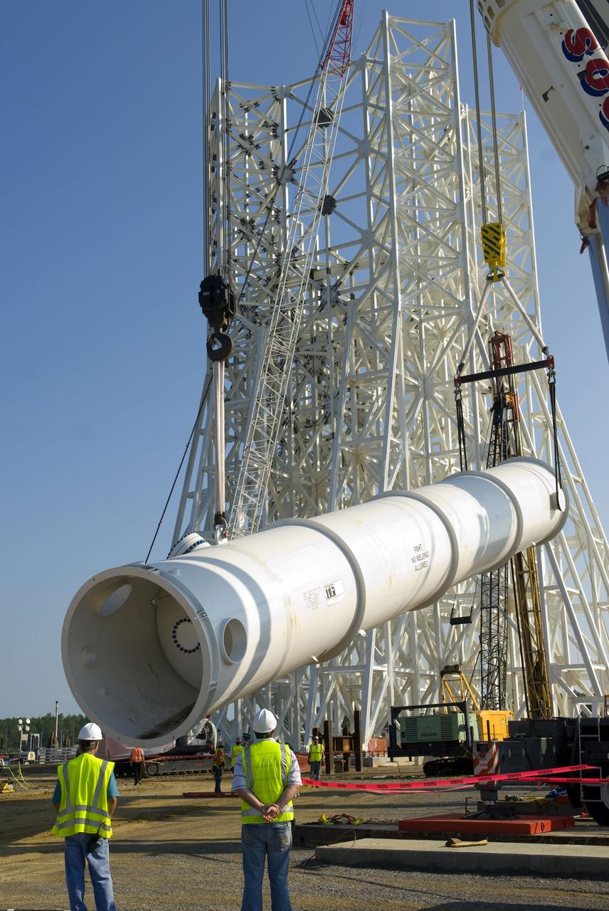
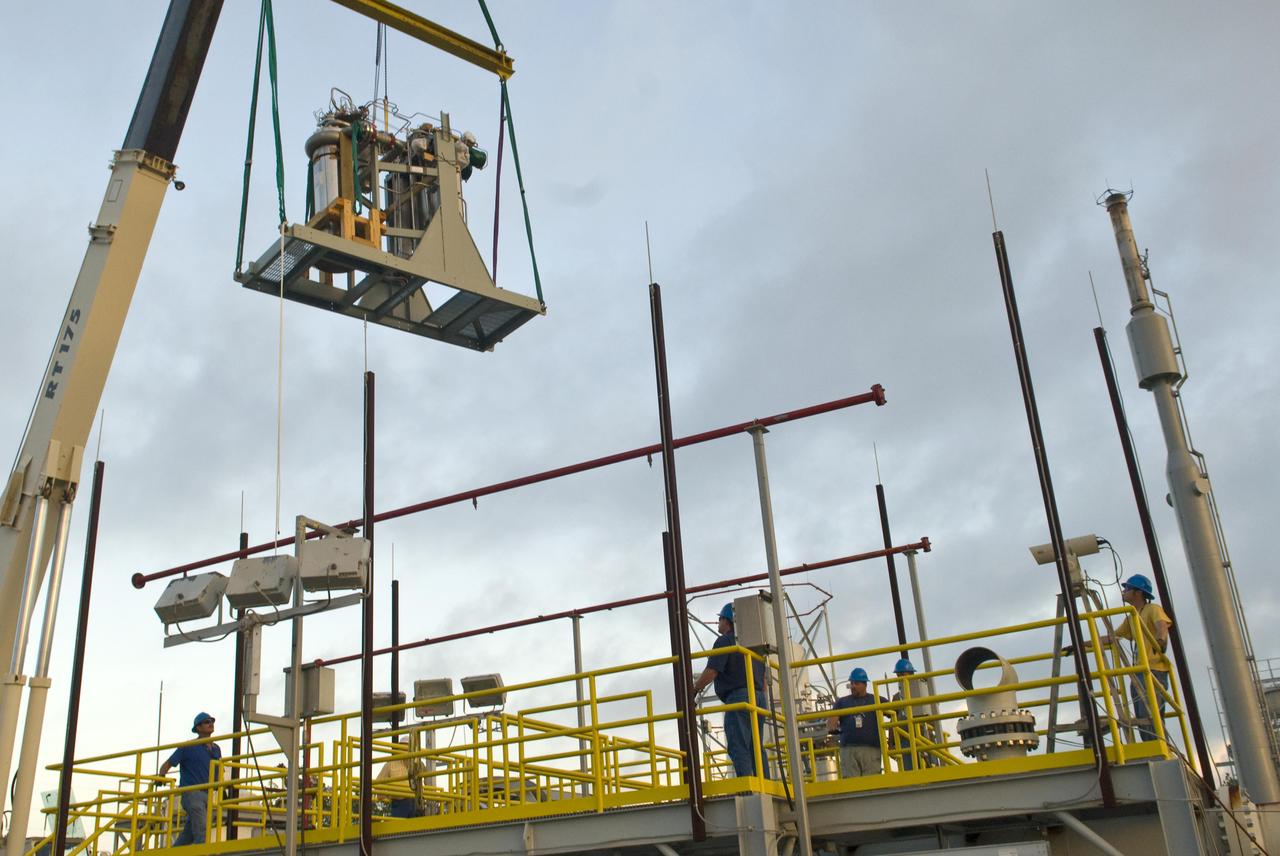
Employees at Stennis Space Center continue work on the A-3 Test Stand. As shown, a section of the test cell is lifted for installation on the stand's structural steel frame. Work on the A-3 Test Stand began in 2007. It is scheduled for activation in 2012.

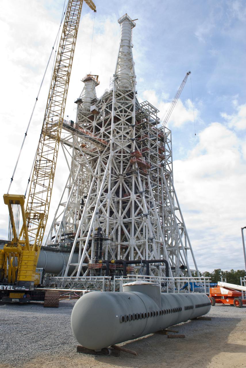
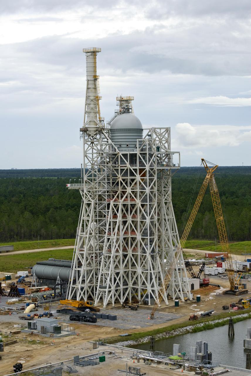
Rocket engine propellant tanks and cell dome top the A-3 Test Stand under construction at Stennis Space Center. The stand will test next-generation rocket engines that could carry humans beyond low-Earth orbit into deep space once more.
Rocket engine propellant tanks and cell dome top the A-3 Test Stand under construction at Stennis Space Center. The stand will test next-generation rocket engines that could carry humans beyond low-Earth orbit into deep space once more.

A Stennis Space Center employee works March 2, 2012, to further construction of the A-3 Test Stand, which will enable simulated high-altitude testing of next-generation rocket engines.
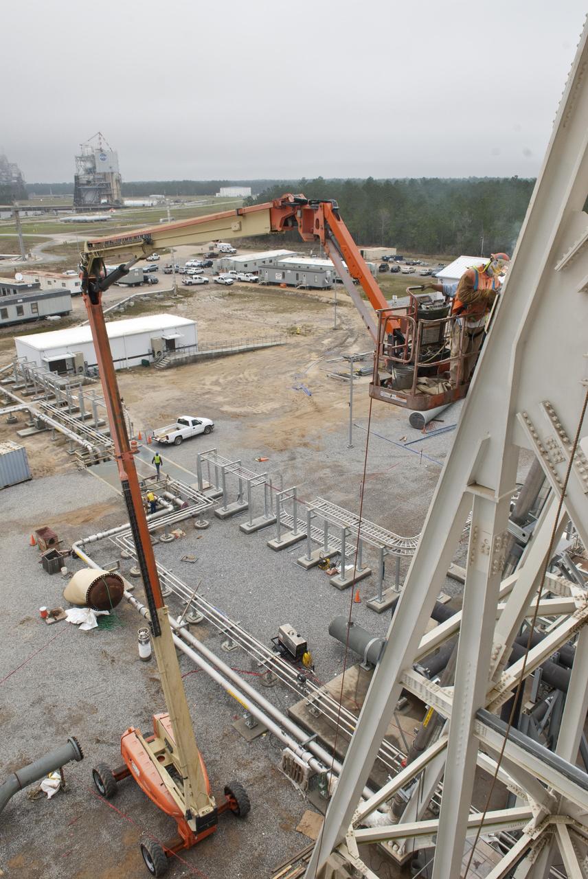
A Stennis Space Center employee works March 2, 2012, to further construction of the A-3 Test Stand, which will enable simulated high-altitude testing of next-generation rocket engines.
Stennis Space Center employees continue work on the A-3 Test Stand test cell. The stand is being built to test next-generation rocket engines that could carry humans beyond low-Earth orbit into deep space.
The A-3 Test Stand under construction at Stennis Space Center is set for completion and activation in 2013. It will allow operators to conduct simulated high-altitude testing on the next-generation J-2X rocket engine.

The A-3 Test Stand under construction at Stennis Space Center is set for completion and activation in 2013. It will allow operators to conduct simulated high-altitude testing on the next-generation J-2X rocket engine.
Stennis Space Center Director Patrick Scheuermann presents center director coins to employees following the 'topping out' of the A-3 Test Stand with placement of test cell dome on April 13. The stand is the first large test structure built at Stennis since the 1960s.
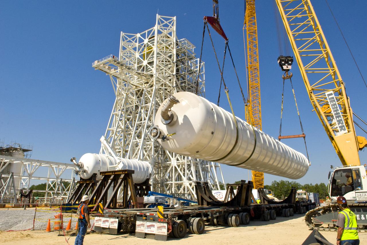
An 80,000-gallon liquid hydrogen tank is placed at the A-3 Test Stand construction site on Sept. 24, 2010. The tank will provide propellant for tests of next-generation rocket engines at the stand. It will be placed upright on top of the stand, helping to increase the overall height to 300 feet. Once completed, the A-3 Test Stand will enable operators to test rocket engines at simulated altitudes of up to 100,000 feet. The A-3 stand is the first large rocket engine test structure to be built at Stennis Space Center since the 1960s.
A 35,000-gallon liquid oxygen tank is placed at the A-3 Test Stand construction site on Sept. 24, 2010. The tank will provide propellant for tests of next-generation rocket engines at the stand. It will be placed upright on top of the stand, helping to increase the overall height to 300 feet. Once completed, the A-3 Test Stand will enable operators to test rocket engines at simulated altitudes of up to 100,000 feet. The A-3 stand is the first large rocket engine test structure to be built at Stennis Space Center since the 1960s.
Structural steel work is completed on the 235-foot A-3 Test Stand at NASA's John C. Stennis Space Center. Stennis engineers celebrated this key milestone in construction April 9.
Structural steel work is completed on the 235-foot A-3 Test Stand at NASA's John C. Stennis Space Center. Stennis engineers celebrated this key milestone in construction April 9.
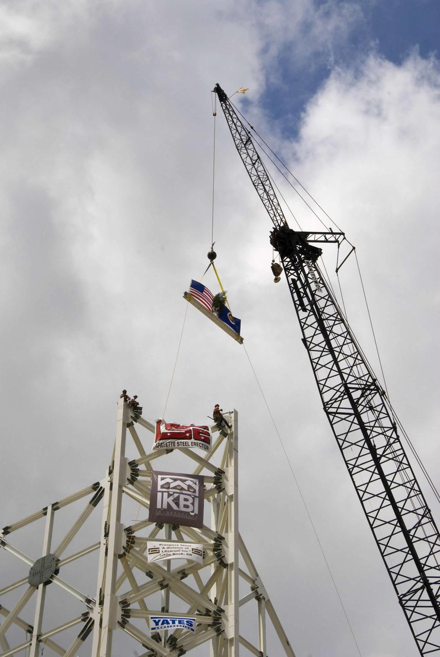
The final structural steel beam, bearing flags and the names of project workers, is hoisted and fastened into place atop the A-3 Test Stand.
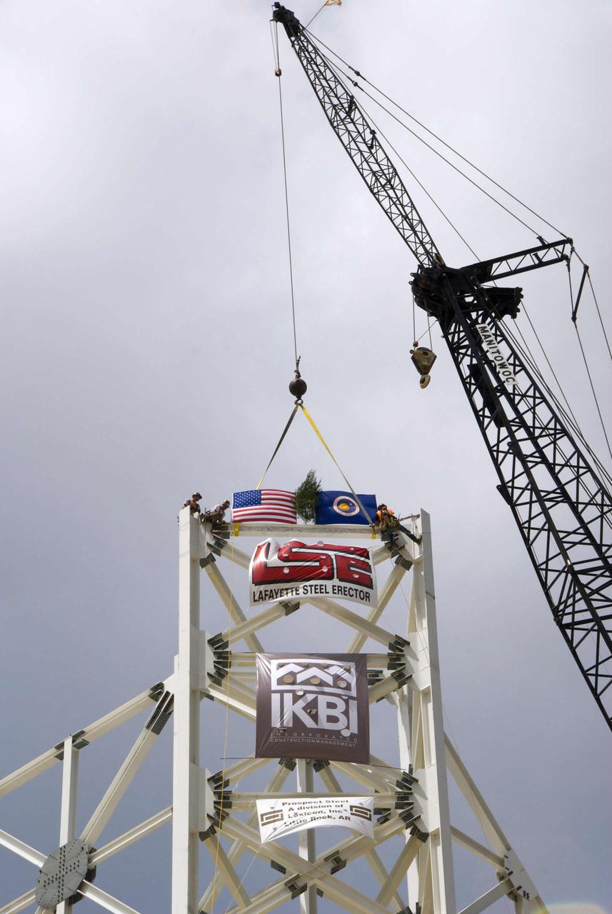
The final structural steel beam, bearing flags and the names of project workers, is hoisted and fastened into place atop the A-3 Test Stand.
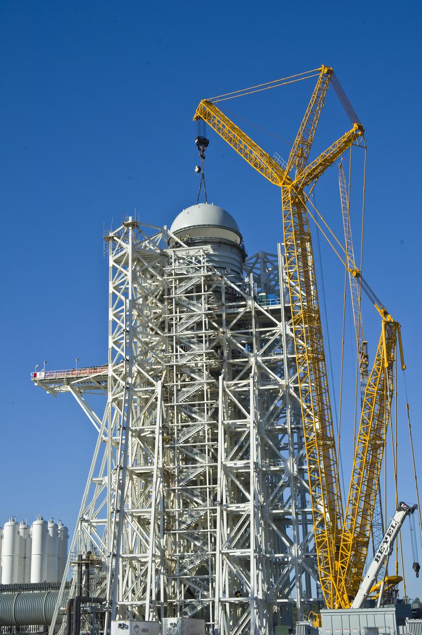
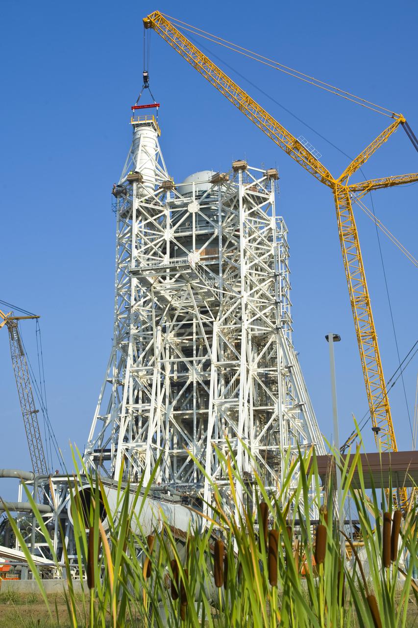
A construction 'topping out' milestone was reached April 13 with placement of the test cell dome atop NASA's new A-3 Test Stand at Stennis Space Center. NASA broke ground in 2007 for the new stand, which is being built to provide simulated high-altitude testing for next-generation rocket engines that could carry humans into deep space.

A water tank is lifted into place at the A-3 Test Stand being built at NASA's John C. Stennis Space Center. Fourteen water, liquid oxygen (LOX) and isopropyl alcohol (IPA) tanks are being installed to support the chemical steam generators to be used on the A-3 Test Stand. The IPA and LOX tanks will provide fuel for the generators. The water will allow the generators to produce steam that will be used to reduce pressure inside the stand's test cell diffuser, enabling operators to simulate altitudes up to 100,000 feet. In that way, operators can perform the tests needed on rocket engines being built to carry humans back to the moon and possibly beyond. The A-3 Test Stand is set for completion and activation in 2011.
A water tank is lifted into place at the A-3 Test Stand being built at NASA's John C. Stennis Space Center. Fourteen water, liquid oxygen (LOX) and isopropyl alcohol (IPA) tanks are being installed to support the chemical steam generators to be used on the A-3 Test Stand. The IPA and LOX tanks will provide fuel for the generators. The water will allow the generators to produce steam that will be used to reduce pressure inside the stand's test cell diffuser, enabling operators to simulate altitudes up to 100,000 feet. In that way, operators can perform the tests needed on rocket engines being built to carry humans back to the moon and possibly beyond. The A-3 Test Stand is set for completion and activation in 2011.
Workers erect the first fabricated steel girders to arrive at the A-3 Test Stand at Stennis Space Center. Steel work began at the construction site Oct. 29 and is scheduled to continue into next spring.
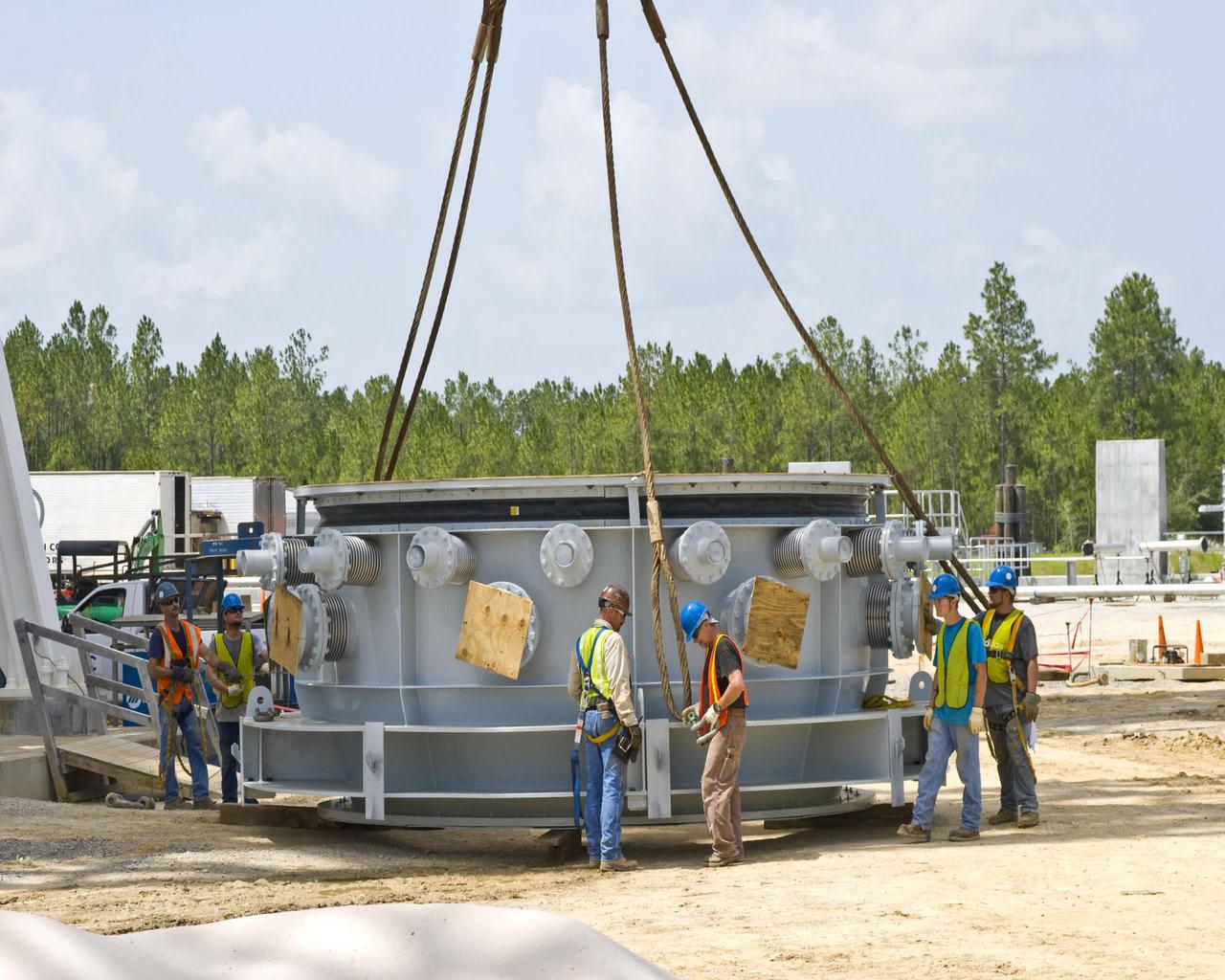
Work on the A-3 Test Stand at Stennis Space Center took a step forward in July with delivery of the first-stage steam ejector July 13. Stennis employees are shown preparing the ejector to be lifted into place on the test stand. When activated in 2012, the A-3 Test Stand will allow operators to test rocket engines at simulated altitudes of 100,000 feet, a critical feature for next-generation engines that will take humans beyond low-Earth orbit once more.
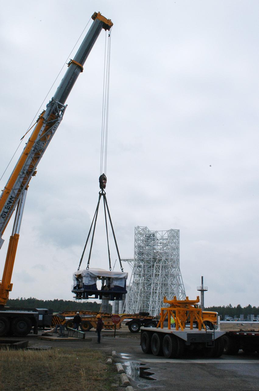
A state-of-the-art thrust measurement system for the A-3 Test Stand under construction at NASA's John C. Stennis Space Center was delivered March 17. Once completed, the A-3 stand (seen in background) will allow simulated high-altitude testing on the next generation of rocket engines for America's space program. Work on the stand began in 2007, with activation scheduled for 2012. The stand is the first major test structure to be built at Stennis since the 1960s. The recently delivered TMS was fabricated by Thrust Measurement Systems in Illinois. It is an advanced calibration system capable of measuring vertical and horizontal thrust loads with an accuracy within 0.15 percent at 225,000 pounds.
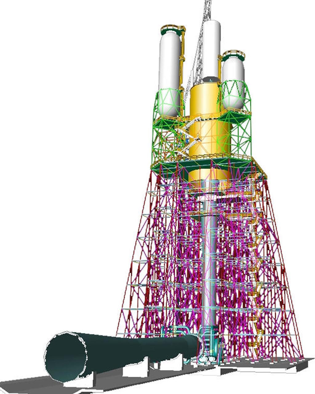
This engineer's concept drawing of the A-3 Test Stand shows the 300-foot-tall structure's open steel frame and large exhaust diffuser.
An isopropyl alcohol (IPA) tank is lifted into place at the A-3 Test Stand being built at NASA's John C. Stennis Space Center. Fourteen IPA, water and liquid oxygen (LOX) tanks are being installed to support the chemical steam generators to be used on the A-3 Test Stand. The IPA and LOX tanks will provide fuel for the generators. The water will allow the generators to produce steam that will be used to reduce pressure inside the stand's test cell diffuser, enabling operators to simulate altitudes up to 100,000 feet. In that way, operators can perform the tests needed on rocket engines being built to carry humans back to the moon and possibly beyond. The A-3 Test Stand is set for completion and activation in 2011.

A liquid oxygen (LOX) tank is lifted into place at the A-3 Test Stand being built at NASA's John C. Stennis Space Center. Fourteen LOX, isopropyl alcohol (IPA) and water tanks are being installed to support the chemical steam generators to be used on the A-3 Test Stand. The IPA and LOX tanks will provide fuel for the generators. The water will allow the generators to produce steam that will be used to reduce pressure inside the stand's test cell diffuser, enabling operators to simulate altitudes up to 100,000 feet. In that way, operators can perform the tests needed on rocket engines being built to carry humans back to the moon and possibly beyond. The A-3 Test Stand is set for completion and activation in 2011.
A liquid oxygen (LOX) tank is lifted into place at the A-3 Test Stand being built at NASA's John C. Stennis Space Center. Fourteen LOX, isopropyl alcohol (IPA) and water tanks are being installed to support the chemical steam generators to be used on the A-3 Test Stand. The IPA and LOX tanks will provide fuel for the generators. The water will allow the generators to produce steam that will be used to reduce pressure inside the stand's test cell diffuser, enabling operators to simulate altitudes up to 100,000 feet. In that way, operators can perform the tests needed on rocket engines being built to carry humans back to the moon and possibly beyond. The A-3 Test Stand is set for completion and activation in 2011.

Fabricated steel began arriving by truck Oct. 24 for construction of the A-3 Test Stand that will be used to test the engine for the nation's next generation of moon rockets. Within days workers from Lafayette Steel Erector Inc. began assembling the 16 steel stages needed on the foundation and footings poured in the previous year.
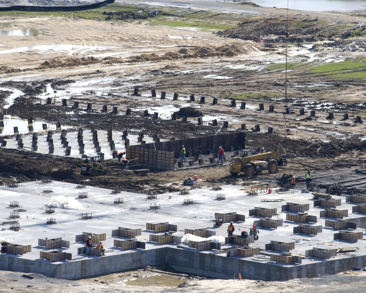
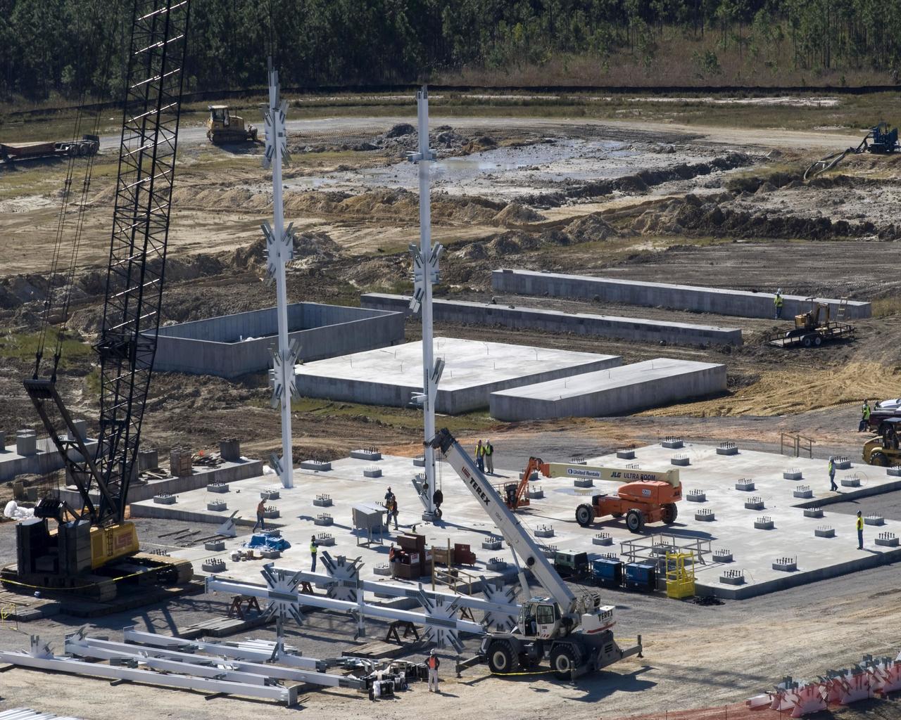
The concrete foundation placed Dec. 18 (foreground) for Stennis Space Center's future A-3 Test Stand has almost completely cured by early January, according to Bo Clarke, NASA's contracting officer technical representative for the foundation contract. By late December, construction on foundations for many of the test stand's support structures - diffuser, liquid oxygen, isopropyl alcohol and water tanks and gaseous nitrogen bottle battery - had begun with the installation of (background) `mud slabs.' The slabs provide a working surface for the reinforcing steel and foundation forms.
Construction of the A-3 Test Stand at Stennis Space Center continued June 8 with installation of a 35,000-gallon liquid oxygen tank atop the steel structure. The stand is being built to test next-generation rocket engines that will carry humans into deep space once more. The LOX tank and a liquid hydrogen tank to be installed atop the stand later will provide propellants for testing the engines. The A-3 Test Stand is scheduled for completion and activation in 2013.
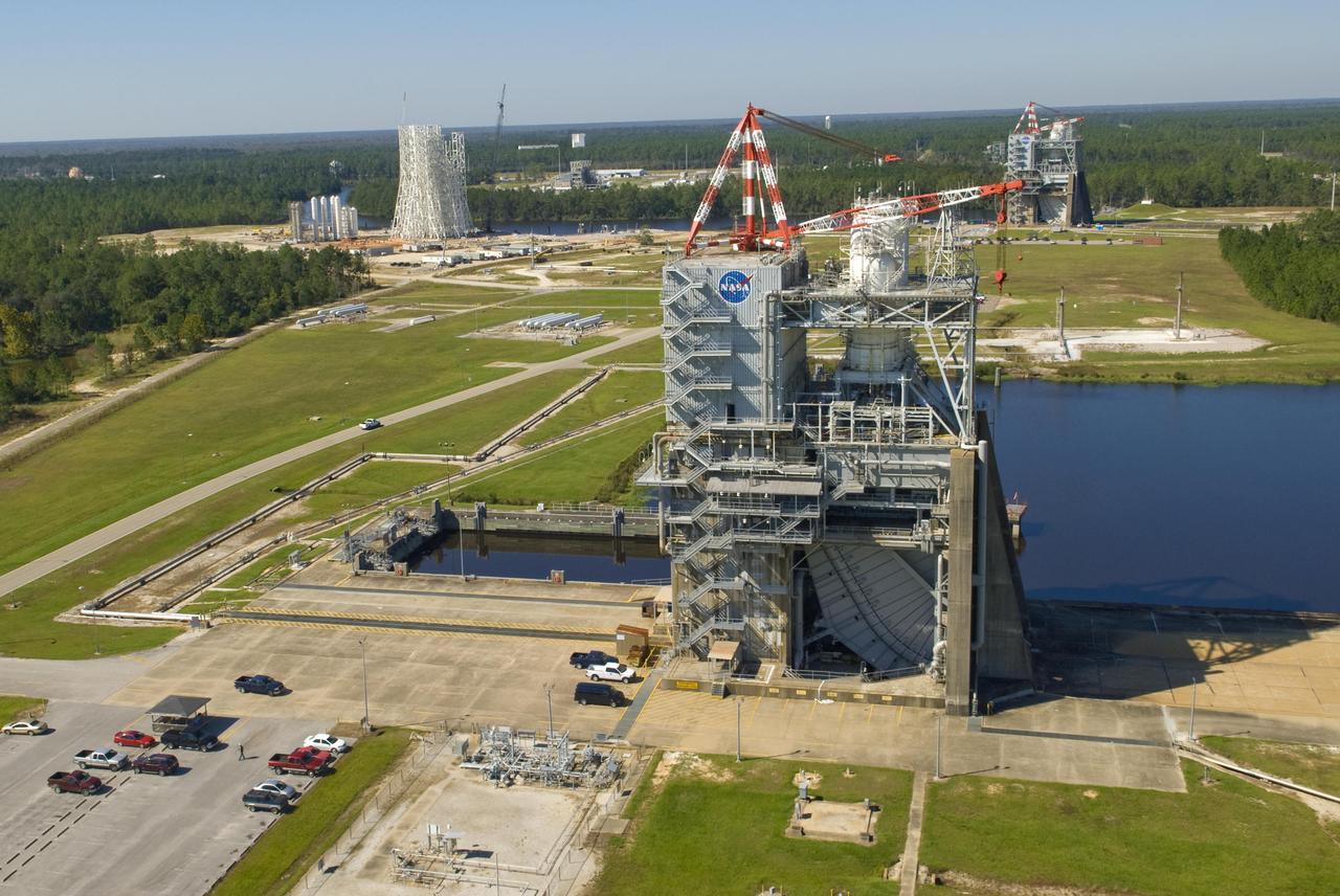
In addition to the historic A-2 Test Stand (foreground) and A-1 Test Stand (back right), construction of a new A-3 Test Stand (back left) is under way at Stennis Space Center. The new stand will allow operators to test next-generation rocket engines at simulated altitudes of 100,000 feet. Such testing is critical for engines that will carry humans into deep space once more.
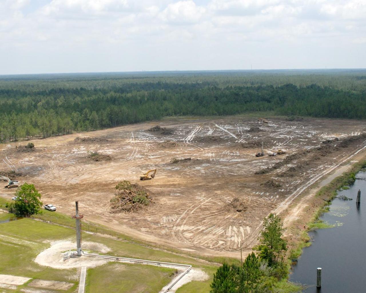
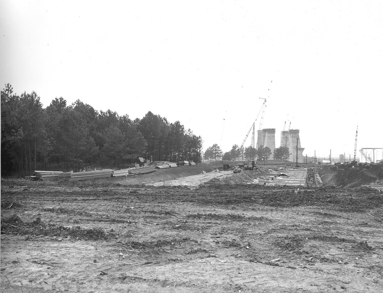
Work to clear the site for the A-3 Test Stand progresses quickly, as seen in this photo taken June 18 from atop the A-1 Test Stand. The next step in construction at 19-acre site will be the arrival of fill dirt in mid-July, followed by pilings and piling caps.
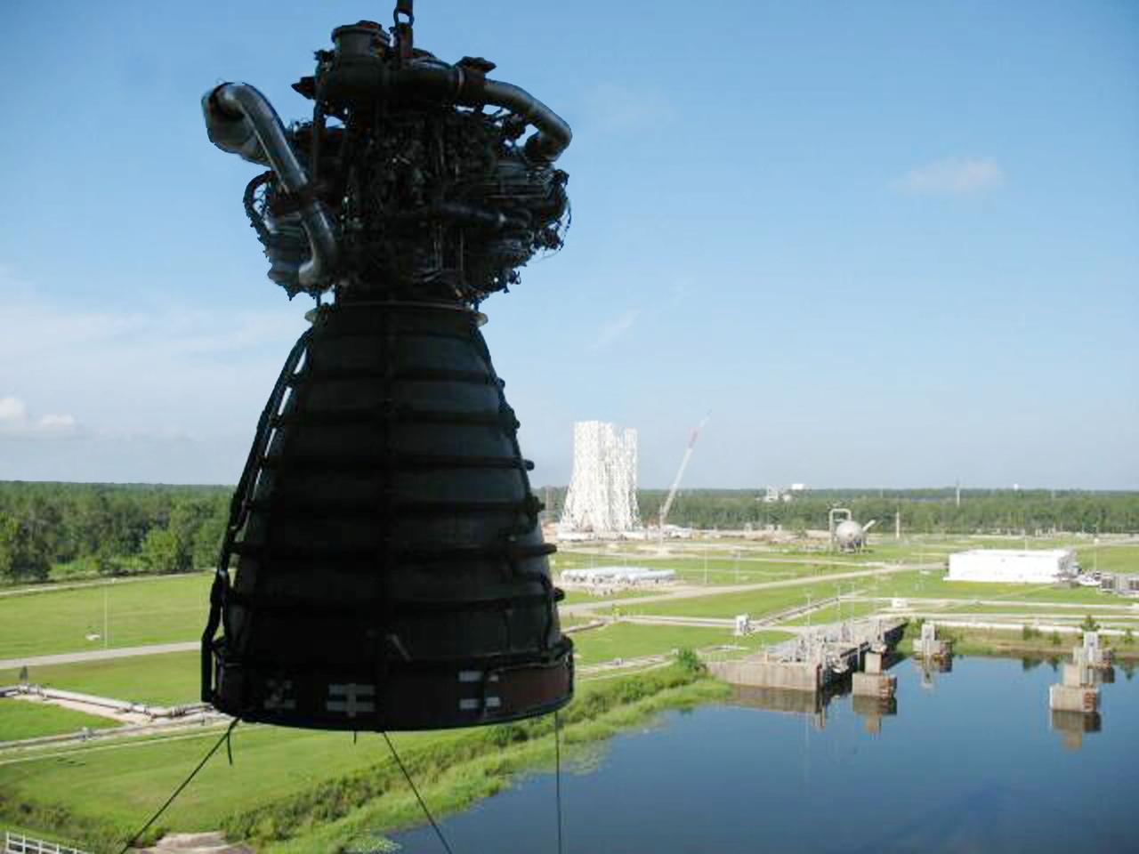
Space shuttle main engine No. 0525 is lifted from the A-2 Test Stand at Stennis Space Center against the backdrop of the new A-3 Test Stand under construction, offering a glimpse of the past and future in the nation's space exploration program. With the shuttle program set to end in 2010, Stennis conducted the last planned space shuttle main engine test on July 29 and now is deactivating the A-2 Test Stand to a safe 'standby' status.
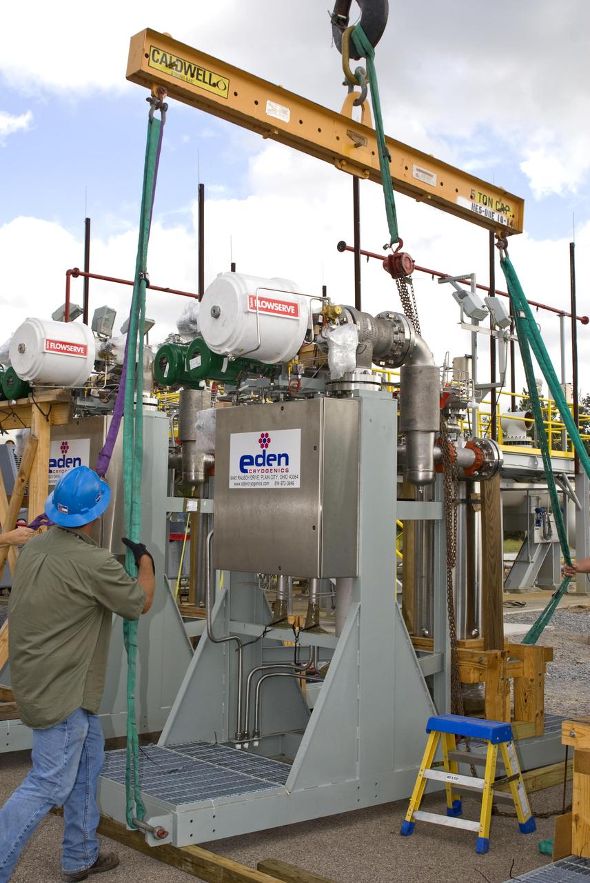
The first of nine chemical steam generator (CSG) units that will be used on the A-3 Test Stand is prepared for installation Oct. 24, 2010, at John C. Stennis Space Center. The unit was installed at the E-2 Test Stand for verification and validation testing before it is moved to the A-3 stand. Steam generated by the nine CSG units that will be installed on the A-3 stand will create a vacuum that allows Stennis operators to test next-generation rocket engines at simulated altitudes up to 100,000 feet.
Water storage vessels for the A-3 Test Stand are delivered to Stennis on Aug. 12.
Water storage vessels for the A-3 Test Stand are delivered to Stennis on Aug. 12.
Stennis Space Center employees marked another construction milestone July 25 with installation of the 85,000-gallon liquid hydrogen tank atop the A-3 Test Stand. The 300-foot-tall stand is being built to test next-generation rocket engines that could carry humans into deep space once more. The liquid hydrogen tank and a 35,000-gallon liquid oxygen tank installed atop the steel structure earlier in June will provide fuel propellants for testing the engines.
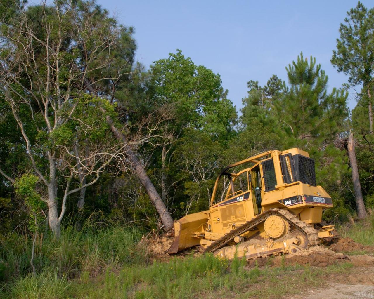
Tree clearing for the site of the new A-3 Test Stand at Stennis Space center began June 13. NASA's first new large rocket engine test stand to be built since the site's inception, A-3 construction begins a historic era for America's largest rocket engine test complex. The 300-foot-tall structure is scheduled for completion in August 2010. A-3 will perform altitude tests on the Constellation's J-2X engine that will power the upper stage of the Ares I crew launch vehicle and earth departure stage of the Ares V cargo launch vehicle. The Constellation Program, NASA's plan for carrying out the nation's Vision for Space Exploration, will return humans to the moon and eventually carry them to Mars and beyond.
The first of nine chemical steam generator (CSG) units that will be used on the A-3 Test Stand is hoisted into place at the E-2 Test Stand at John C. Stennis Space Center on Oct. 24, 2010. The unit was installed at the E-2 stand for verification and validation testing before it is moved to the A-3 stand. Steam generated by the nine CSG units that will be installed on the A-3 stand will create a vacuum that allows Stennis operators to test next-generation rocket engines at simulated altitudes up to 100,000 feet.
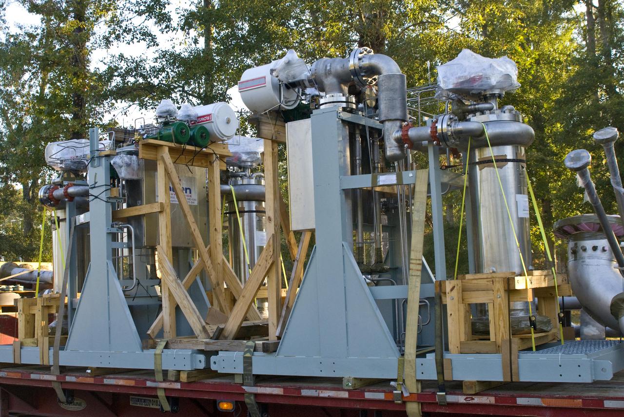
The first of nine chemical steam generator (CSG) units that will be used on the A-3 Test Stand arrived at John. C. Stennis Space Center on Oct. 22, 2010. The unit was installed at the E-2 Test Stand for verification and validation testing before it is moved to the A-3 stand. Steam generated by the nine CSG units that will be installed on the A-3 stand will create a vacuum that allows Stennis operators to test next-generation rocket engines at simulated altitudes up to 100,000 feet.
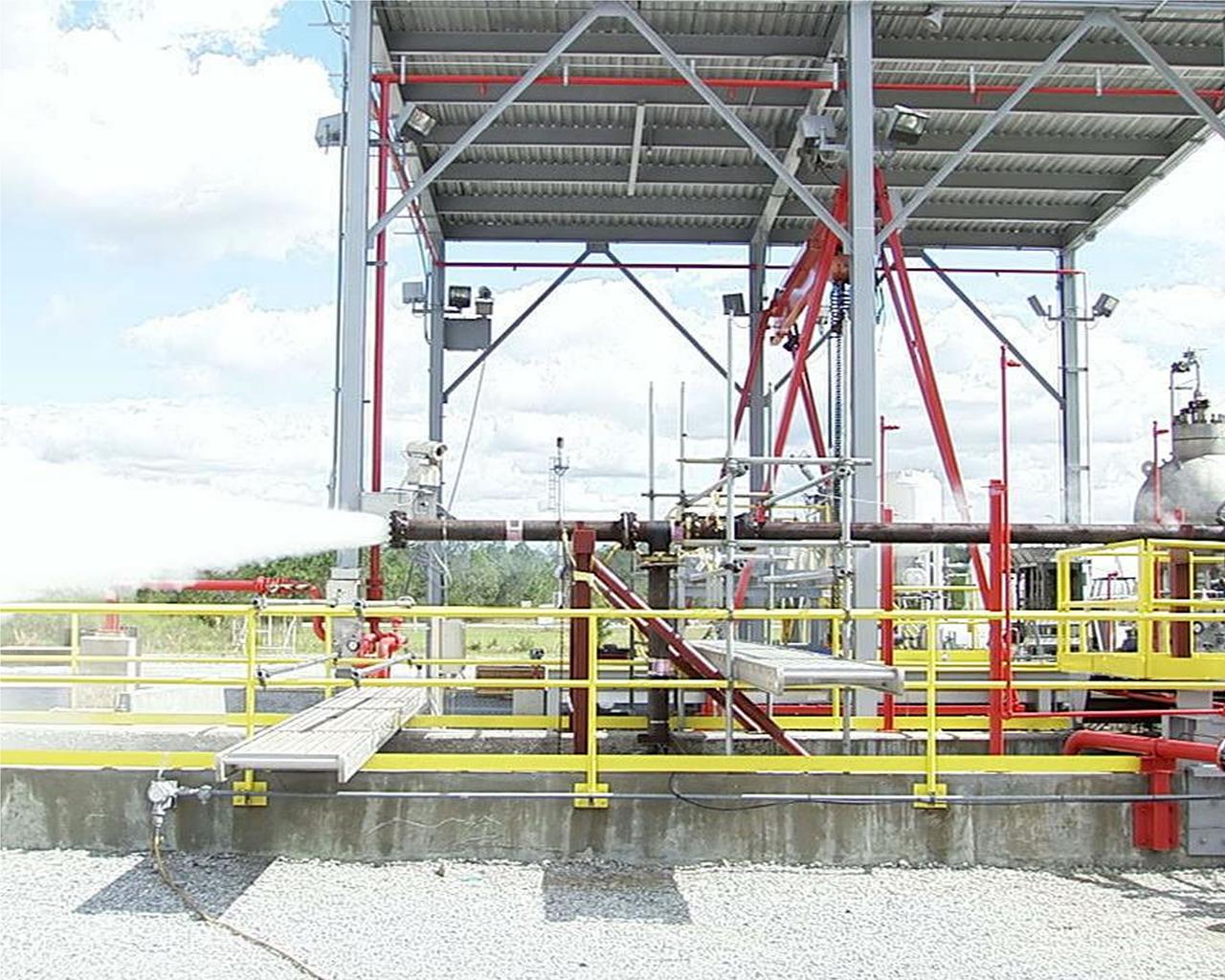
Phase 2 of the A-3 Test Facility Subscale Diffuser Risk Mitigation Project at Stennis Space Center reached a milestone Oct. 25 when the E-3 Test Facility produced superheated (500+ degrees) steam for approximately 3 seconds at more than 400 psi. The test team, led by Barry Robinson of NASA's Test Projects Office, followed that success with further tests to lengthen the duration of steam production. On Nov. 1, they were able to maintain a consistent pressure and temperature of steam for 60 seconds. In December, the team began Phase 3 of the testing, providing data for the design and procurement to build the full-scale version of the steam diffuser for SSC's A-3 Test Stand.
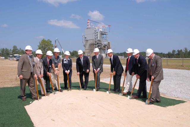
NASA officials and government leaders participated in a groundbreaking event for a new rocket engine test stand at NASA's Stennis Space Center, Miss. Pictured (left to right) are Deputy Associate Administrator for Exploration Systems Doug Cooke, Pratt & Whitney Rocketdyne President Jim Maser, Stennis Space Center Director Richard Gilbrech, NASA Associate Administrator for Exploration Systems Scott Horowitz, NASA Deputy Administrator Shana Dale, Mississippi Gov. Haley Barbour, Sen. Thad Cochran, Sen. Trent Lott, Rep. Gene Taylor, SSC's Deputy Director Gene Goldman, and SSC's A-3 Project Manager Lonnie Dutreix. Stennis' A-3 Test Stand will provide altitude testing for NASA's developing J-2X engine. That engine will power the upper stages of NASA's Ares I and Ares V rockets. A-3 is the first large test stand to be built at SSC since the site's inception in the 1960s.

Stennis Space Center engineers celebrated a key milestone in construction of the A-3 Test Stand on April 9 - completion of structural steel work. Workers with Lafayette (La.) Steel Erector Inc. placed the last structural steel beam atop the stand during a noon ceremony attended by more than 100 workers and guests.
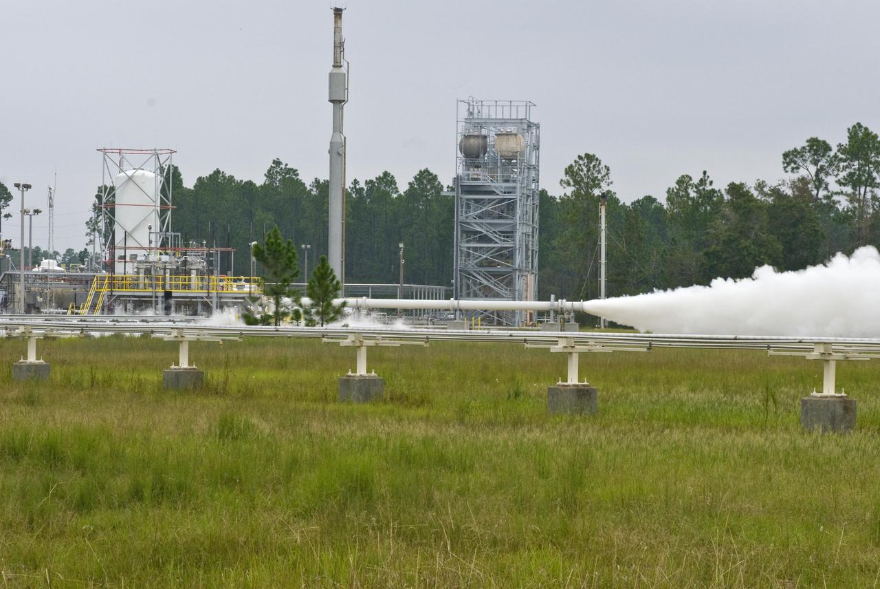
Operators at the E-3 Test Stand at NASA's John C. Stennis Space Center completed 32 acoustics tests April 16-28, designed to gather critical information for future space launches. Stennis operators investigated lift-off acoustics that can damage space vehicle components by testing the benefits of injecting water onto the upper surface of the launch pad to suppress sound. The Stennis tests provided critical data to determine what can be gained from this approach.

John C. Stennis Space Center employees complete installation of a chemical steam generator (CSG) unit at the site's E-2 Test Stand. On Oct. 24, 2010. The unit will undergo verification and validation testing on the E-2 stand before it is moved to the A-3 Test Stand under construction at Stennis. Each CSG unit includes three modules. Steam generated by the nine CSG units that will be installed on the A-3 stand will create a vacuum that allows Stennis operators to test next-generation rocket engines at simulated altitudes up to 100,000 feet.
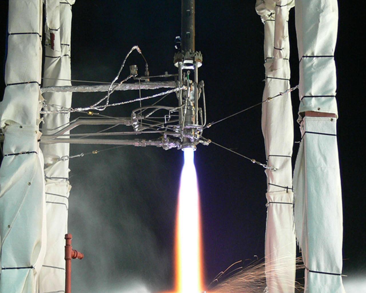
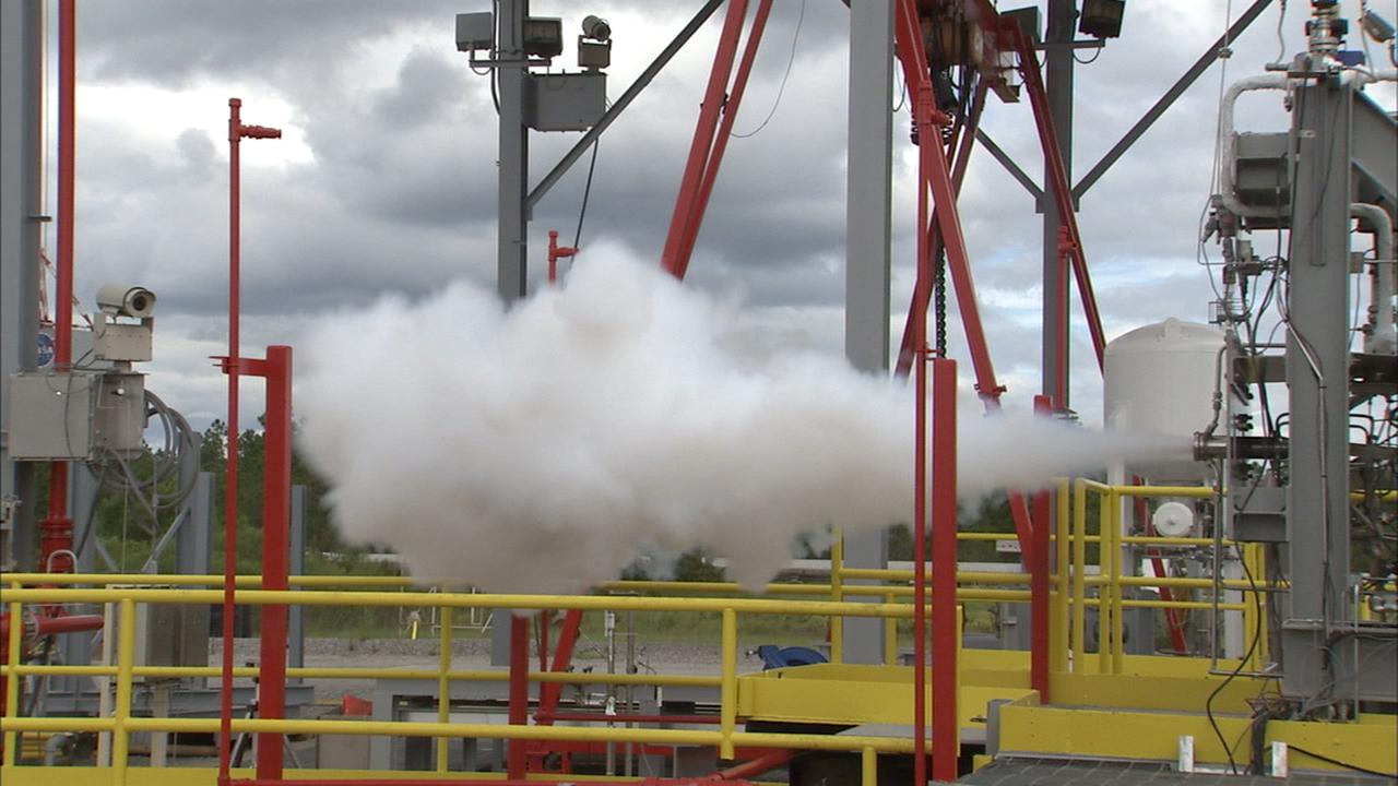
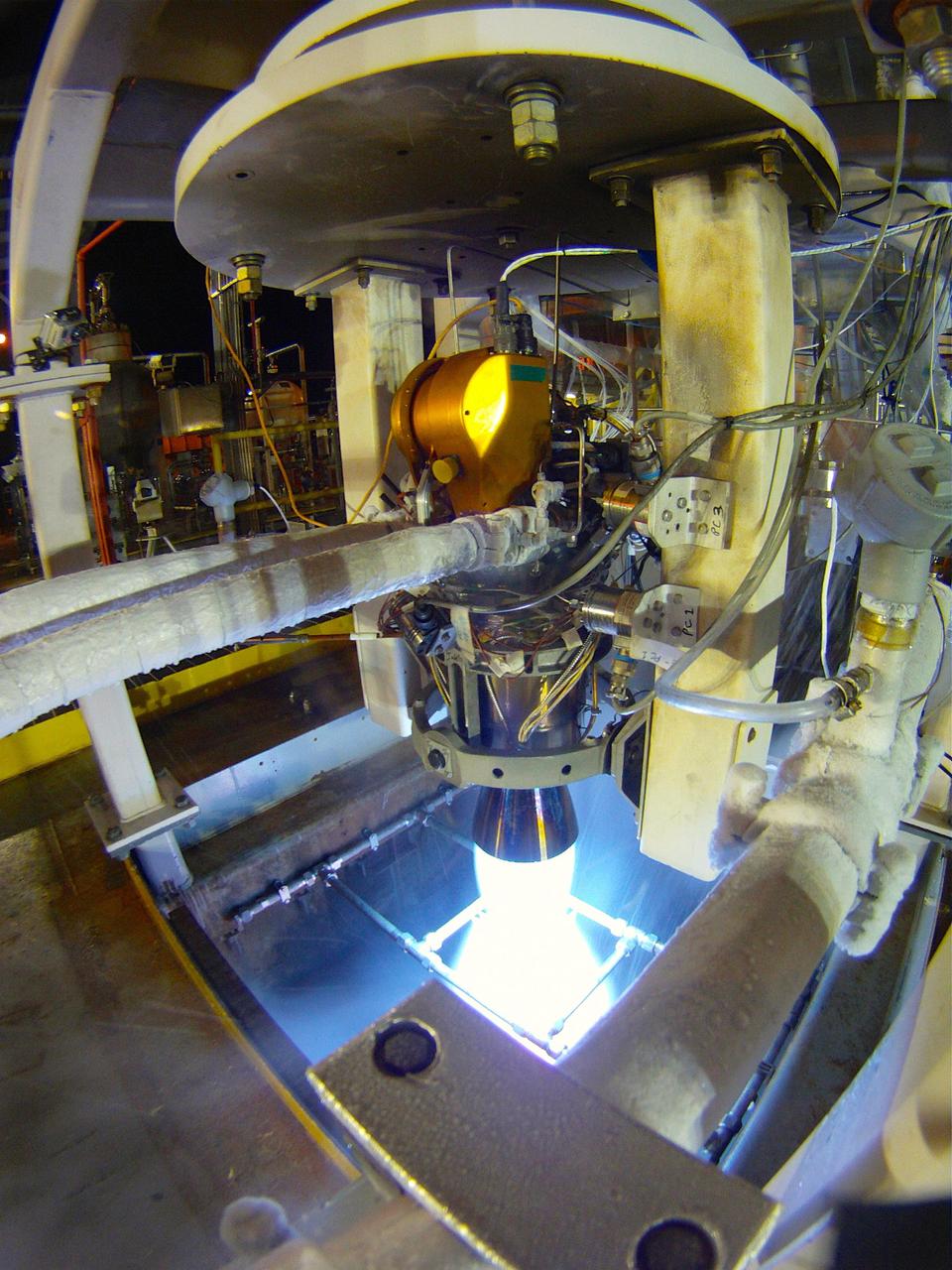
A plume of steam signals a successful engine start of the J-2X rocket engine on the A-3 Test Stand at Stennis Space Center on July 26. The 3.7-second test was the second on the next-generation engine, which is being developed for NASA by Pratt & Whitney Rocketdyne.
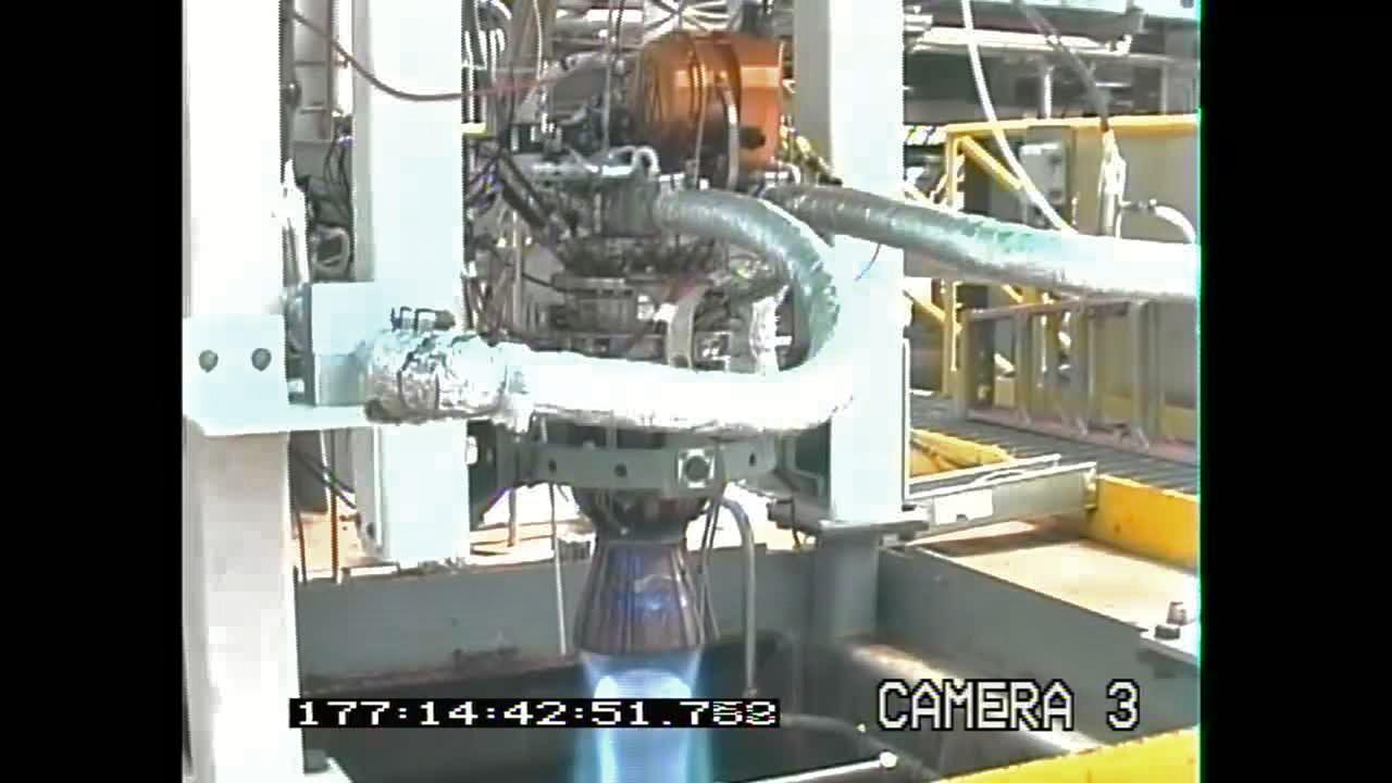
A frame grab from a mounted video camera on the E-3 Test Stand at Stennis Space Center documents testing of the new Project Morpheus engine. The new liquid methane, liquid oxygen engine will power the Morpheus prototype lander, which could one day evolve to carry cargo safely to the moon, asteroids or Mars surfaces.
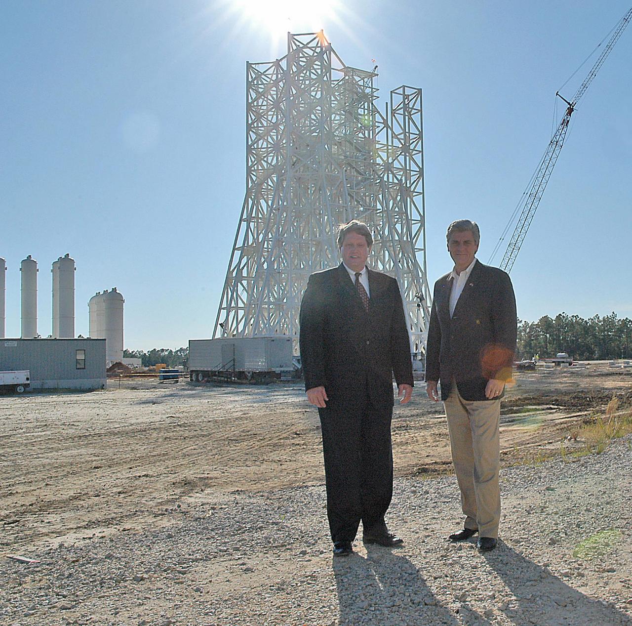
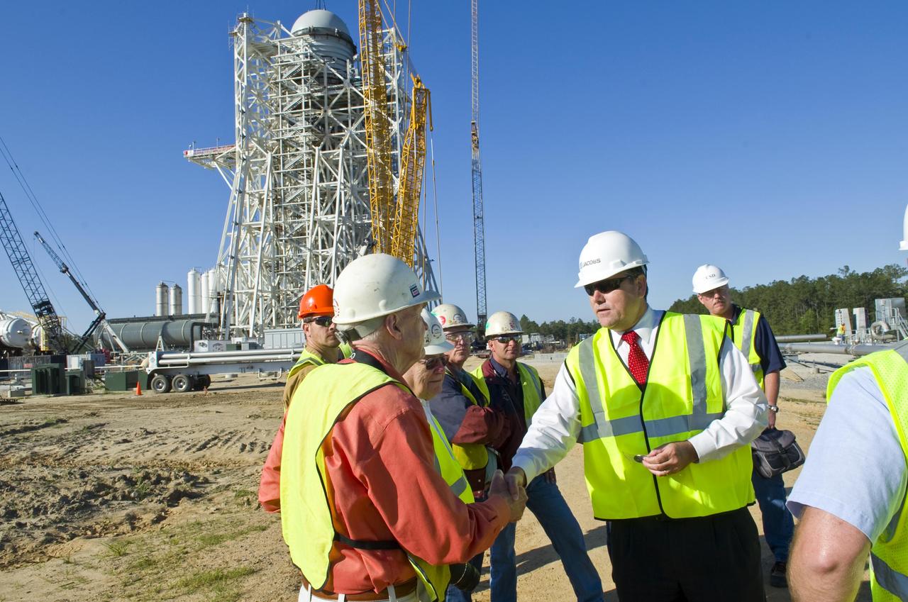
Stennis Space Center Director Gene Goldman (left) stands with Mississippi Lt. Gov. Phil Bryant at the A-3 Test Stand construction site during an Oct. 1 visit by the state official. During his tour, Bryant was updated on construction of the first large test stand at Stennis since the 1960s. The A-3 stand will be used to conduct simulated high-altitude testing on the next generation of rocket engines that will take humans back to the moon and possibly beyond. In addition to touring Stennis facilities, Bryant visited the INFINITY Science Center construction site, where he was updated on work under way to construct a 72,000-square-foot facility that will showcase the science underpinning the missions of NASA and resident agencies at Stennis.
Tests begun at Stennis Space Center's E Complex Sept. 13 evaluated a liquid oxygen lead for engine start performance, part of the A-3 Test Facility Subscale Diffuser Risk Mitigation Project at SSC's E-3 Test Facility. Phase 1 of the subscale diffuser project, completed Sept. 24, was a series of 18 hot-fire tests using a 1,000-pound liquid oxygen and gaseous hydrogen thruster to verify maximum duration and repeatability for steam generation supporting the A-3 Test Stand project. The thruster is a stand-in for NASA's developing J-2X engine, to validate a 6 percent scale version of A-3's exhaust diffuser. Testing the J-2X at altitude conditions requires an enormous diffuser. Engineers will generate nearly 4,600 pounds per second of steam to reduce pressure inside A-3's test cell to simulate altitude conditions. A-3's exhaust diffuser has to be able to withstand regulated pressure, temperatures and the safe discharge of the steam produced during those tests. Before the real thing is built, engineers hope to work out any issues on the miniature version. Phase 2 testing is scheduled to begin this month.
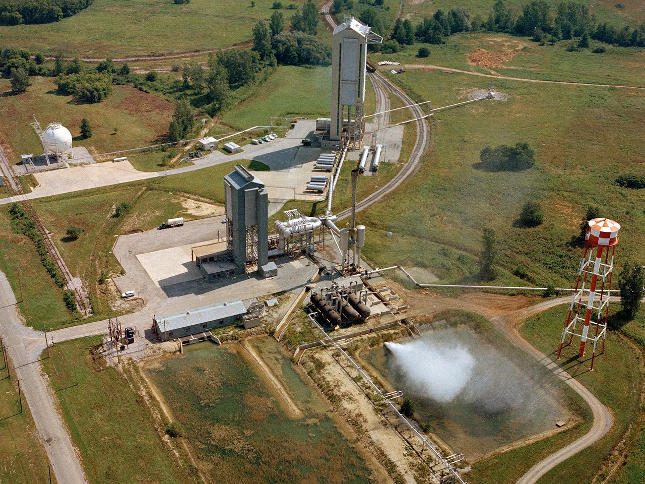
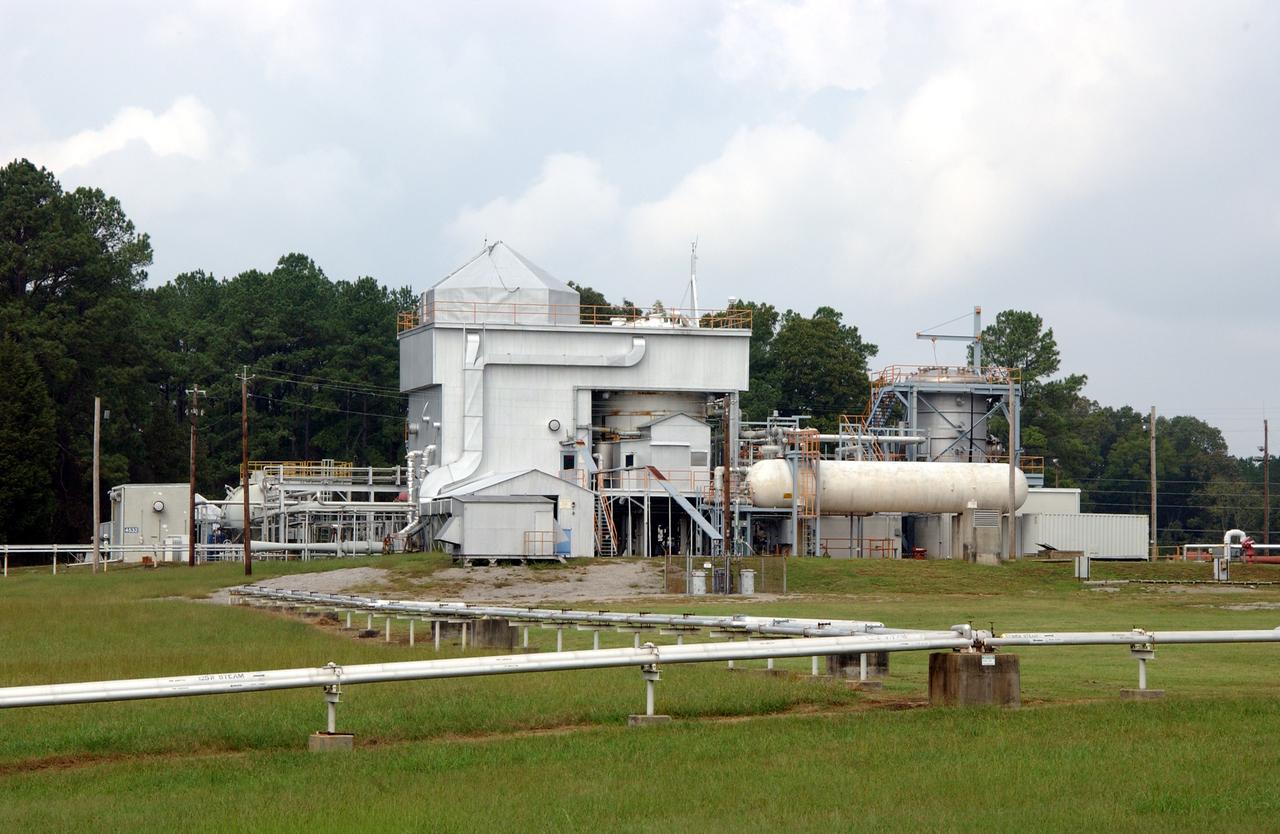
Operation of the High Energy Rocket Engine Research Facility (B-1), left, and Nuclear Rocket Dynamics and Control Facility (B-3) at the National Aeronautics and Space Administration’s (NASA) Plum Brook Station in Sandusky, Ohio. The test stands were constructed in the early 1960s to test full-scale liquid hydrogen fuel systems in simulated altitude conditions. Over the next decade each stand was used for two major series of liquid hydrogen rocket tests: the Nuclear Engine for Rocket Vehicle Application (NERVA) and the Centaur second-stage rocket program. The different components of these rocket engines could be studied under flight conditions and adjusted without having to fire the engine. Once the preliminary studies were complete, the entire engine could be fired in larger facilities. The test stands were vertical towers with cryogenic fuel and steam ejector systems. B-1 was 135 feet tall, and B-3 was 210 feet tall. Each test stand had several levels, a test section, and ground floor shop areas. The test stands relied on an array of support buildings to conduct their tests, including a control building, steam exhaust system, and fuel storage and pumping facilities. A large steam-powered altitude exhaust system reduced the pressure at the exhaust nozzle exit of each test stand. This allowed B-1 and B-3 to test turbopump performance in conditions that matched the altitudes of space.
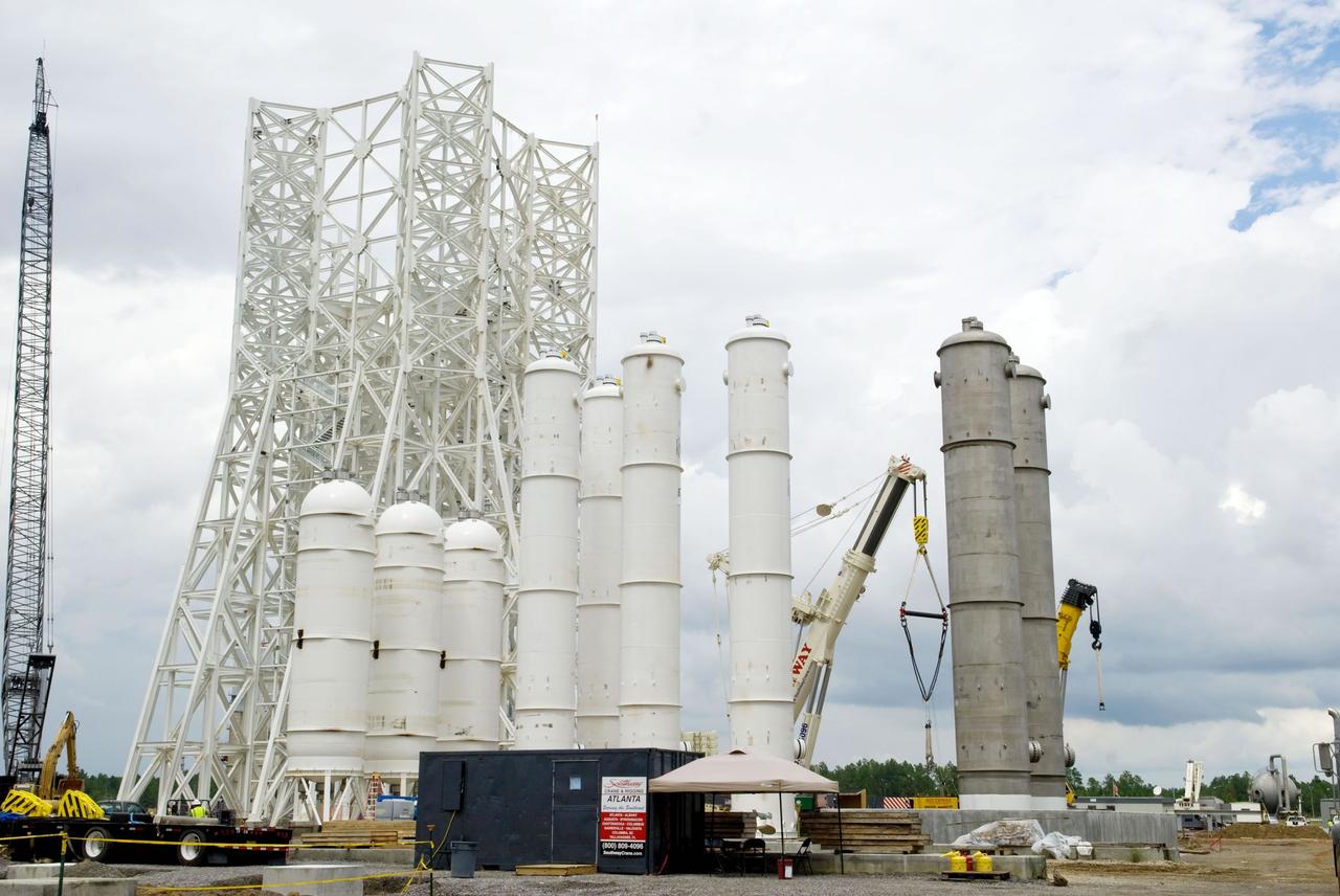
Construction of the A-3 Test Stand approaches another milestone with delivery and installation of water, isopropyl alcohol (IPA) and liquid oxygen (LOX) tanks. The three LOX tanks shown on the left and the two IPA tanks shown on the right are all 35,000 gallons each. The four water tanks in the center are 39,000 gallons each.

Alabama House Minority Leader Anthony Daniels, (Left), and Auburn University President, Dr. Stephen Leahy, were part of the Leadership Alabama group that viewed the SLS Liquid Hydrogen test stand at Marshall Space Flight Center on 3/7/19.
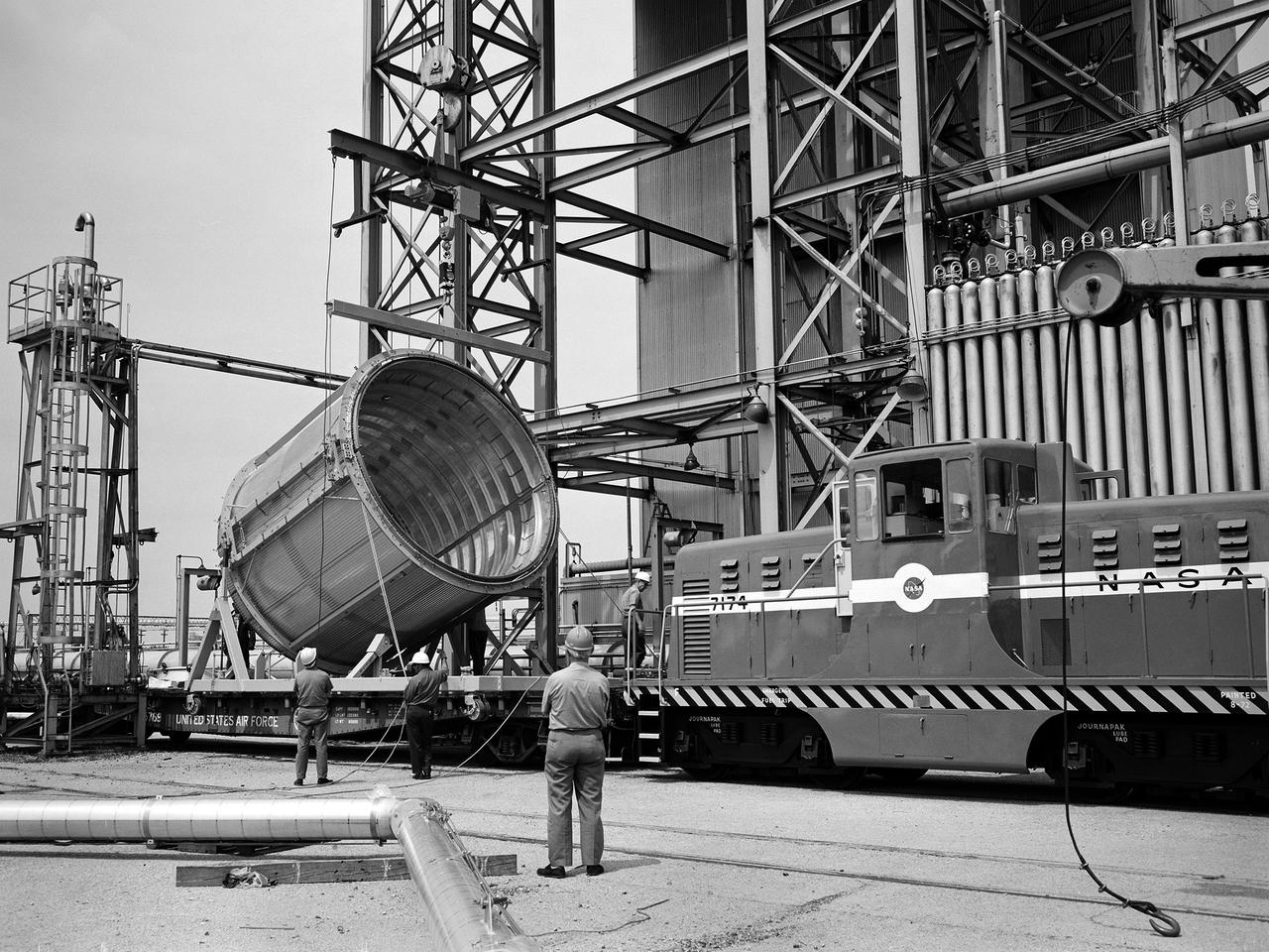
A section of the Centaur Standard Shroud transported to Nuclear Rocket Dynamics and Control Facility, or B-3 Test Stand, at the National Aeronautics and Space Administration’s (NASA) Plum Brook Station. B-3 was built in the early 1960s to test full-scale liquid hydrogen fuel systems in simulated altitude conditions. The facility was used in 1972, however, for testing of the Centaur Standard Shroud’s ejection system. In the late 1960s NASA engineers were planning the ambitious new Viking mission to send two rover vehicles to the surface of Mars. The Viking rovers were the heaviest payloads ever attempted and were over three times the weight of Atlas-Centaur’s previous heaviest payload. Consequently, NASA engineers selected the more powerful the Titan III rocket booster to mate with the Centaur. Concurrently, General Dynamics was in the process of introducing a new Centaur model for Titan—the D-1T. The biggest change for the D-1T was a completely new shroud designed by Lockheed, called the Centaur Standard Shroud. The shroud, its insulation, the Centaur ground-hold purge system, and the hydrogen tank venting system were all studied in B-3. After more than two years of preparations, the tests were run between April and July 1973. The tests determined the ultimate flight loads on two axes, established the Centaur’s load sharing, the level of propellant boiloff during launch holds, and the vent system capacity. The Centaur Standard Shroud performed flawlessly during the August 20 and September 9, 1975 launches of Viking 1 and 2.
Overall view of test stand 4693 in the west test area. The stand is scheduled to have another 3 story section added
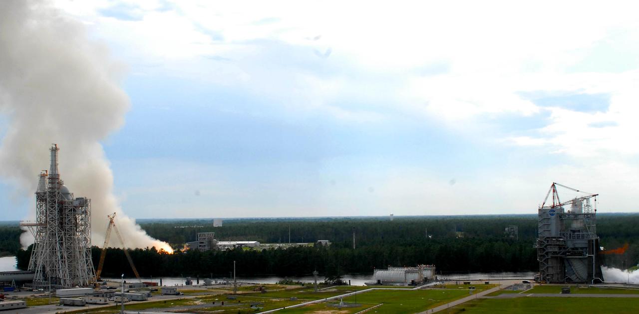
Two large-engine tests were conducted simultaneously for the first time at Stennis Space Center on Aug. 16. A plume on the left indicates a test on the facility's E-1 Test Stand. On the right, a finger of fire indicates a test under way on the A-1 Test Stand. In another first, both tests were conducted by female engineers. The image was taken from atop the facility's A-2 Test Stand, offering a panoramic view that includes the new A-3 Test Stand under construction to the left.

NASA recorded a historic week Nov. 5-9, conducting tests on all three stands in the E Test Complex at John C. Stennis Space Center. Inset images show the types of tests conducted on the E-1 Test Stand (right), the E-2 Test Stand (left) and the E-3 Test Stand (center). The E-1 photo is from an early October test and is provided courtesy of Blue Origin. Other photos are from tests conducted the week of Nov. 5.
E-2 Test Stand team members at Stennis Space Center conducted their first series of tests on a three-module chemical steam generator unit Sept. 15. All three modules successfully fired during the tests. The chemical steam generator is a critical component for the A-3 Test Stand under construction at Stennis.

Stennis Space Center employees maneuver a new thrust measurement system in preparation for its installation on the A-1 Test Stand on March 3. The system was fabricated by Thrust Measurement Systems in Illinois and represents a state-of-the-art upgrade from the equipment used on the stand for more than 40 years. The A-1 Test Stand is being upgraded to provide testing for the next generation of rocket engines for America's space program.
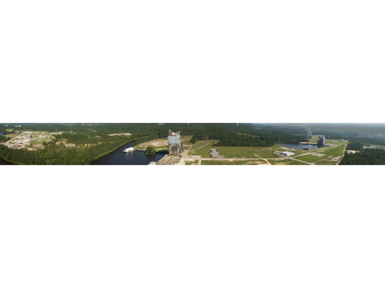
photo taken from the top of the new A-3 Test Stand at Stennis Space Center offers a panoramic view of the A, B and E test complexes at the south Mississippi faci

A photo taken from the top of the new A-3 Test Stand at Stennis Space Center offers a panoramic view of the A, B and E test complexes at the south Mississippi facility.

NASA engineers test a chemical steam generator (CSG) unit on the E-2 Test Stand at John C. Stennis Space Center on Nov. 6. The test was one of 27 conducted in Stennis' E Test Complex the week of Nov. 5. Twenty-seven CSG units will be used on the new A-3 Test Stand at Stennis to produce a vacuum that allows testing of engines at simulated altitudes up to 100,000 feet.
A test of NASA's liquid oxygen, liquid methane Project Morpheus engine is conducted Nov. 8 on the E-3 Test Stand at John C. Stennis Space Center. The test was one of 27 conducted in Stennis' E Test Complex the week of Nov. 5. Twenty-seven tests were conducted in a three-day period during the week, on three different rocket engines/components and on three E Complex test stands.
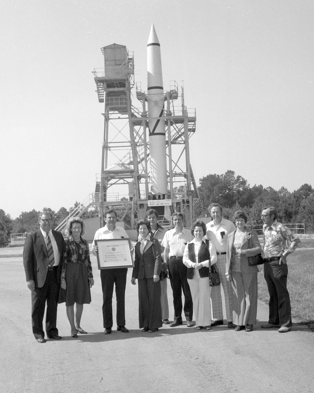
On October 02, 1976, Marshall Space Flight Center’s (MSFC) Redstone test stand was received into the National Registry of Historical Places. Photographed in front of the Redstone test stand along with their wives are (left to right), Madison County Commission Chairman James Record, Dr. William R. Lucas, MSFC Center Director from June 15, 1974 until July 3, 1986, (holding certificate), Ed, Buckbee, Space and Rocket Center Director; Harvie Jones, Huntsville Architect; Dick Smith; and Joe Jones.
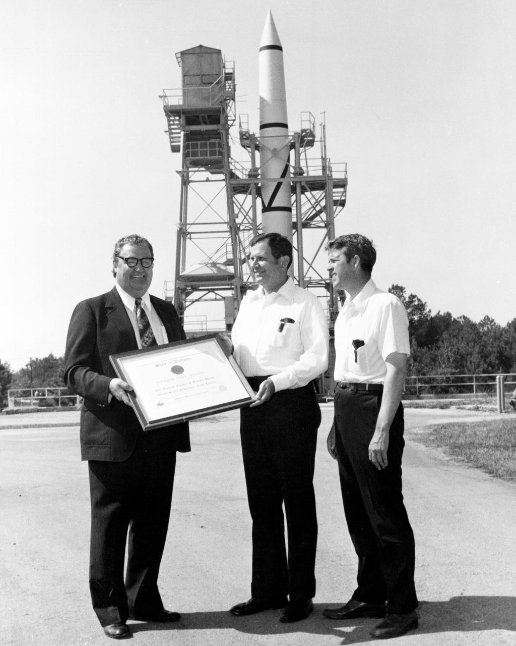
On October 02, 1976, Marshall Space Flight Center’s (MSFC) Redstone test stand was received into the National Registry of Historical Places. Photographed in front of the Redstone test stand are Dr. William R. Lucas, MSFC Center Director from June 15, 1974 until July 3, 1986, as he is accepting a certificate of registration from Madison County Commission Chairman James Record, and Huntsville architect Harvie Jones.
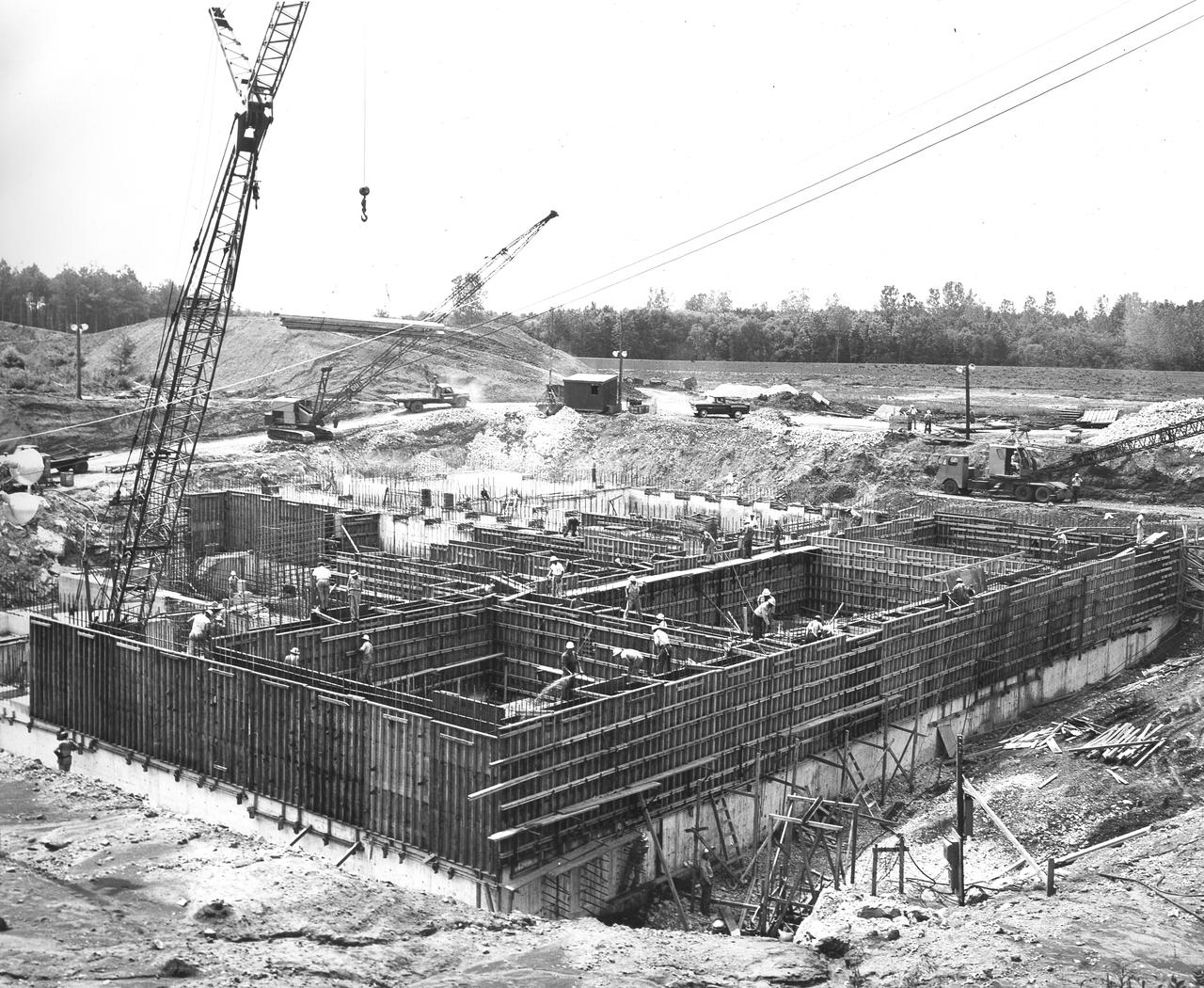
At its founding, the Marshall Space Flight Center (MSFC) inherited the Army’s Jupiter and Redstone test stands, but much larger facilities were needed for the giant stages of the Saturn V. From 1960 to 1964, the existing stands were remodeled and a sizable new test area was developed. The new comprehensive test complex for propulsion and structural dynamics was unique within the nation and the free world, and they remain so today because they were constructed with foresight to meet the future as well as on going needs. Construction of the S-IC Static test stand complex began in 1961 in the west test area of MSFC, and was completed in 1964. The S-IC static test stand was designed to develop and test the 138-ft long and 33-ft diameter Saturn V S-IC first stage, or booster stage, weighing in at 280,000 pounds. Required to hold down the brute force of a 7,500,000-pound thrust produced by 5 F-1 engines, the S-IC static test stand was designed and constructed with the strength of hundreds of tons of steel and 12,000,000 pounds of cement, planted down to bedrock 40 feet below ground level. The foundation walls, constructed with concrete and steel, are 4 feet thick. The base structure consists of four towers with 40-foot-thick walls extending upward 144 feet above ground level. The structure was topped by a crane with a 135-foot boom. With the boom in the upright position, the stand was given an overall height of 405 feet, placing it among the highest structures in Alabama at the time. In addition to the stand itself, related facilities were constructed during this time. North of the massive S-IC test stand, the F-1 Engine test stand was built. Designed to assist in the development of the F-1 Engine, the F-1 test stand is a vertical engine firing test stand, 239 feet in elevation and 4,600 square feet in area at the base. Capability was provided for static firing of 1.5 million pounds of thrust using liquid oxygen and kerosene. Like the S-IC stand, the foundation of the F-1 stand is keyed into the bedrock approximately 40 feet below grade. This photo depicts the construction of the F-1 test stand as of July 3, 1963. All four of its tower legs are well underway.
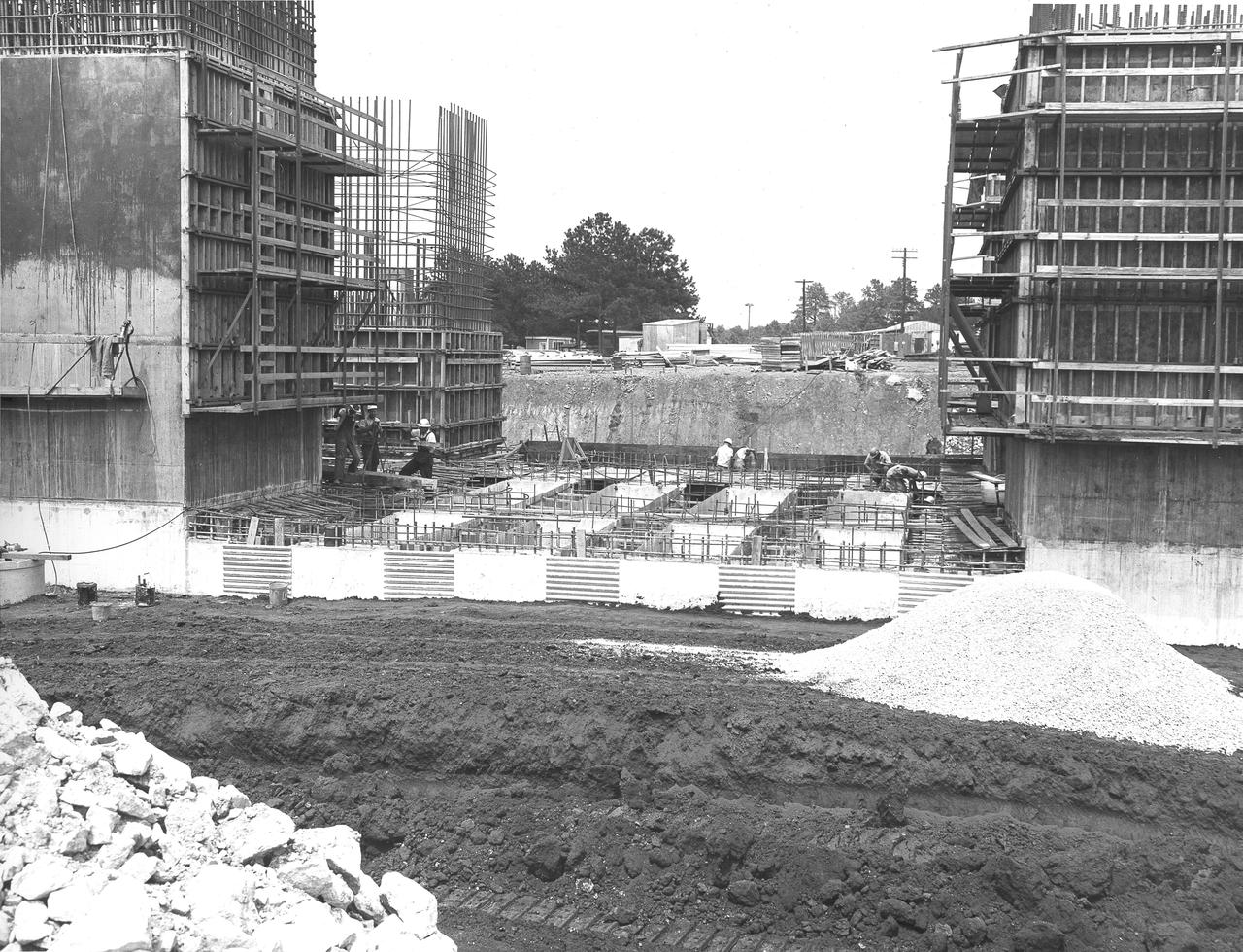
At its founding, the Marshall Space Flight Center (MSFC) inherited the Army’s Jupiter and Redstone test stands, but much larger facilities were needed for the giant stages of the Saturn V. From 1960 to 1964, the existing stands were remodeled and a sizable new test area was developed. The new comprehensive test complex for propulsion and structural dynamics was unique within the nation and the free world, and they remain so today because they were constructed with foresight to meet the future as well as on going needs. Construction of the S-IC Static test stand complex began in 1961 in the west test area of MSFC, and was completed in 1964. The S-IC static test stand was designed to develop and test the 138-ft long and 33-ft diameter Saturn V S-IC first stage, or booster stage, weighing in at 280,000 pounds. Required to hold down the brute force of a 7,500,000-pound thrust produced by 5 F-1 engines, the S-IC static test stand was designed and constructed with the strength of hundreds of tons of steel and 12,000,000 pounds of cement, planted down to bedrock 40 feet below ground level. The foundation walls, constructed with concrete and steel, are 4 feet thick. The base structure consists of four towers with 40-foot-thick walls extending upward 144 feet above ground level. The structure was topped by a crane with a 135-foot boom. With the boom in the upright position, the stand was given an overall height of 405 feet, placing it among the highest structures in Alabama at the time. In addition to the stand itself, related facilities were constructed during this time. Built directly east of the test stand was the Block House, which served as the control center for the test stand. The two were connected by a narrow access tunnel which housed the cables for the controls. This construction photo, taken July 3, 1962, depicts the Block House with a portion of its concrete walls poured and exposed while many are still in the forms stage.
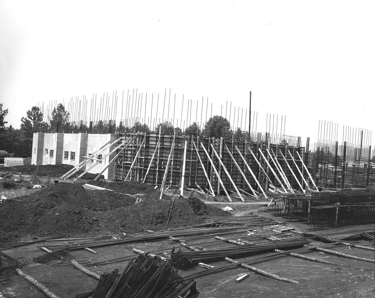
At its founding, the Marshall Space Flight Center (MSFC) inherited the Army’s Jupiter and Redstone test stands, but much larger facilities were needed for the giant stages of the Saturn V. From 1960 to 1964, the existing stands were remodeled and a sizable new test area was developed. The new comprehensive test complex for propulsion and structural dynamics was unique within the nation and the free world, and they remain so today because they were constructed with foresight to meet the future as well as on going needs. Construction of the S-IC Static test stand complex began in 1961 in the west test area of MSFC, and was completed in 1964. The S-IC static test stand was designed to develop and test the 138-ft long and 33-ft diameter Saturn V S-IC first stage, or booster stage, weighing in at 280,000 pounds. Required to hold down the brute force of a 7,500,000-pound thrust produced by 5 F-1 engines, the S-IC static test stand was designed and constructed with the strength of hundreds of tons of steel and 12,000,000 pounds of cement, planted down to bedrock 40 feet below ground level. The foundation walls, constructed with concrete and steel, are 4 feet thick. The base structure consists of four towers with 40-foot-thick walls extending upward 144 feet above ground level. The structure was topped by a crane with a 135-foot boom. With the boom in the upright position, the stand was given an overall height of 405 feet, placing it among the highest structures in Alabama at the time. In addition to the stand itself, related facilities were constructed during this time. Built directly east of the test stand was the Block House, which served as the control center for the test stand. The two were connected by a narrow access tunnel which housed the cables for the controls. This construction photo taken July 3, 1962 depicts the Block House with a portion of its concrete walls poured and exposed while many are still in the forms stage.
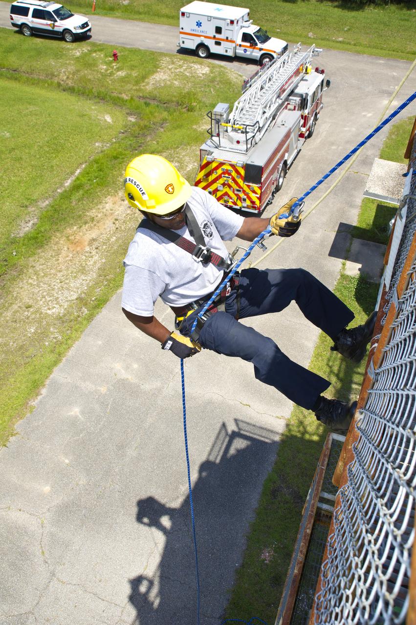
Stennis Space Center firefighter Rodney Boone rappels a tower structure during an onsite training exercise May 11, 2012. The training focused on high-angle rope rescues, which could be needed on the new 300-foot-tall A-3 Test Stand at Stennis.
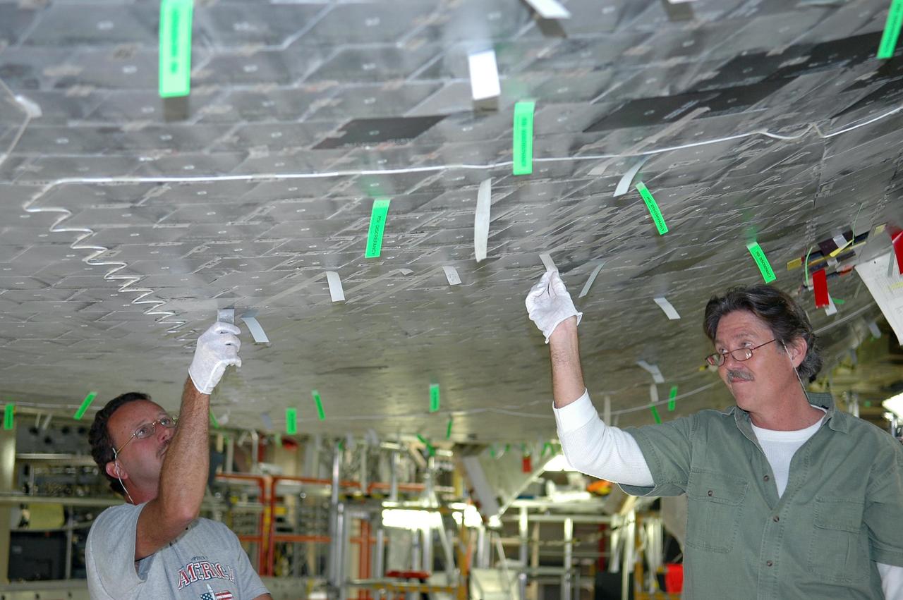
KENNEDY SPACE CENTER, FLA. - In NASA’s Orbiter Processing Facility Bay 3, United Space Alliance technicians Gene Peavler (left) and Richard McGehee (right) are on a stand removing gap filler and inspecting tile repair on Discovery’s underside. Discovery processing is under way for the second return to flight test mission, STS-121.

Stennis Space Center firefighter Rodney Boone rappels a tower structure during an onsite training exercise May 11, 2012. The training focused on high-angle rope rescues, which could be needed on the new 300-foot-tall A-3 Test Stand at Stennis.
This is a ground level view of Test Stand 300 at the east test area of the Marshall Space Flight Center. Test Stand 300 was constructed in 1964 as a gas generator and heat exchanger test facility to support the Saturn/Apollo Program. Deep-space simulation was provided by a 1960 modification that added a 20-ft thermal vacuum chamber and a 1981 modification that added a 12-ft vacuum chamber. The facility was again modified in 1989 when 3-ft and 15-ft diameter chambers were added to support Space Station and technology programs. This multiposition test stand is used to test a wide range of rocket engine components, systems, and subsystems. It has the capability to simulate launch thermal and pressure profiles. Test Stand 300 was designed for testing solid rocket booster (SRB) insulation panels and components, super-insulated tanks, external tank (ET) insulation panels and components, Space Shuttle components, solid rocket motor materials, and advanced solid rocket motor materials.
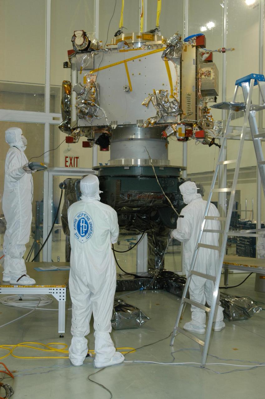
KENNEDY SPACE CENTER, FLA. - At Astrotech Space Operations in Titusville, Fla., the STEREO spacecraft "B" is being moved to a another stand nearby for testing. STEREO stands for Solar Terrestrial Relations Observatory. The STEREO mission is the first to take measurements of the sun and solar wind in 3-dimension. This new view will improve our understanding of space weather and its impact on the Earth. STEREO is expected to lift off aboard a Boeing Delta II rocket on July 22. Photo credit: NASA/George Shelton
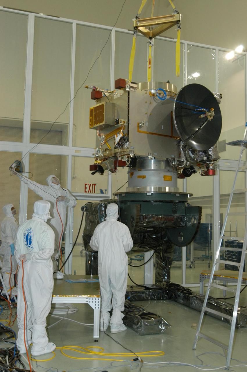
KENNEDY SPACE CENTER, FLA. - At Astrotech Space Operations in Titusville, Fla., a technician works a guideline to the overhead crane as the STEREO spacecraft "B" is being moved to a stand nearby for testing. STEREO stands for Solar Terrestrial Relations Observatory. The STEREO mission is the first to take measurements of the sun and solar wind in 3-dimension. This new view will improve our understanding of space weather and its impact on the Earth. STEREO is expected to lift off aboard a Boeing Delta II rocket on July 22. Photo credit: NASA/George Shelton
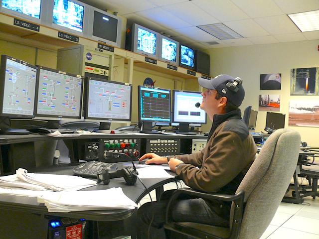
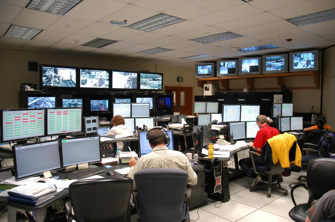
NASA engineer Andy Guymon studies data in the E-3 Test Stand Control Center at John C. Stennis Space Center during testing of NASA's Project Morpheus engine. Nov. 8. The test of the liquid oxygen, liquid methane engine was one of 27 conducted in Stennis' E Test Complex the week of Nov. 5.
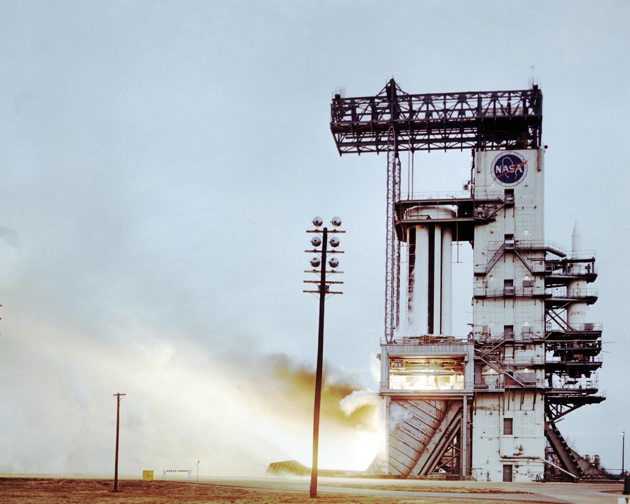
The Saturn project was approved on January 18, 1960 as a program of the highest national priority. The formal test program to prove out the clustered-booster concept was well underway. A series of static tests of the Saturn I booster (S-I stage) began June 3, 1960 at the Marshall Space Flight Center (MSFC). This photograph depicts the Saturn I S-I stage equipped with eight H-1 engines, being successfully test-fired on February 4, 1961. A Juno rocket is visible on the right side of the test stand.
Jason Hopper of NASA (front row), Jody Ladner of Lockheed Martin (back row, left) and Chris Mulkey of NASA prepare to test the Blue Origin BE-3 engine thrust chamber in the E-1 Test Stand Control Center at John C. Stennis Space Center on Nov. 8. The test was one of 27 conducted in Stennis' E Test Complex the week of Nov. 5.
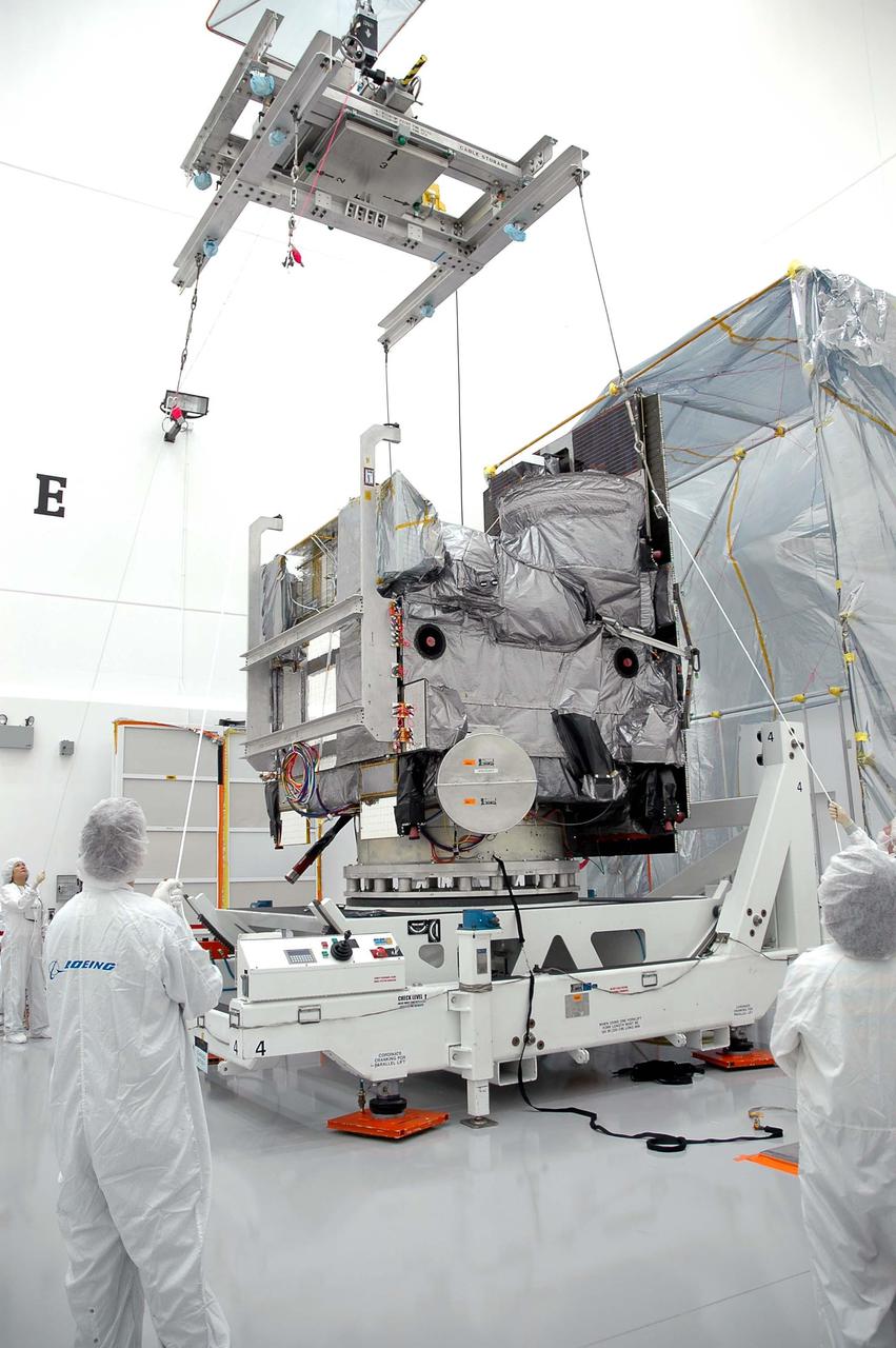
KENNEDY SPACE CENTER, FLA. - At Astrotech in Titusville, Fla., an overhead crane is moved into place above the GOES-N satellite, which is on a rotation stand. The crane will lift the satellite from the rotation stand and move it to a work stand. Since its arrival on March 11, the satellite has been undergoing final testing by Boeing Satellite Systems of the imaging system, instrumentation, communications and power systems. Geostationary Operational Environmental Satellites (GOES) are sponsored by NASA’s Goddard Space Flight Center and the National Oceanic and Atmospheric Administration. GOES-N is targeted to launch May 4 onboard a Boeing expendable launch vehicle Delta IV (4,2) with a 3-burn second stage operation.
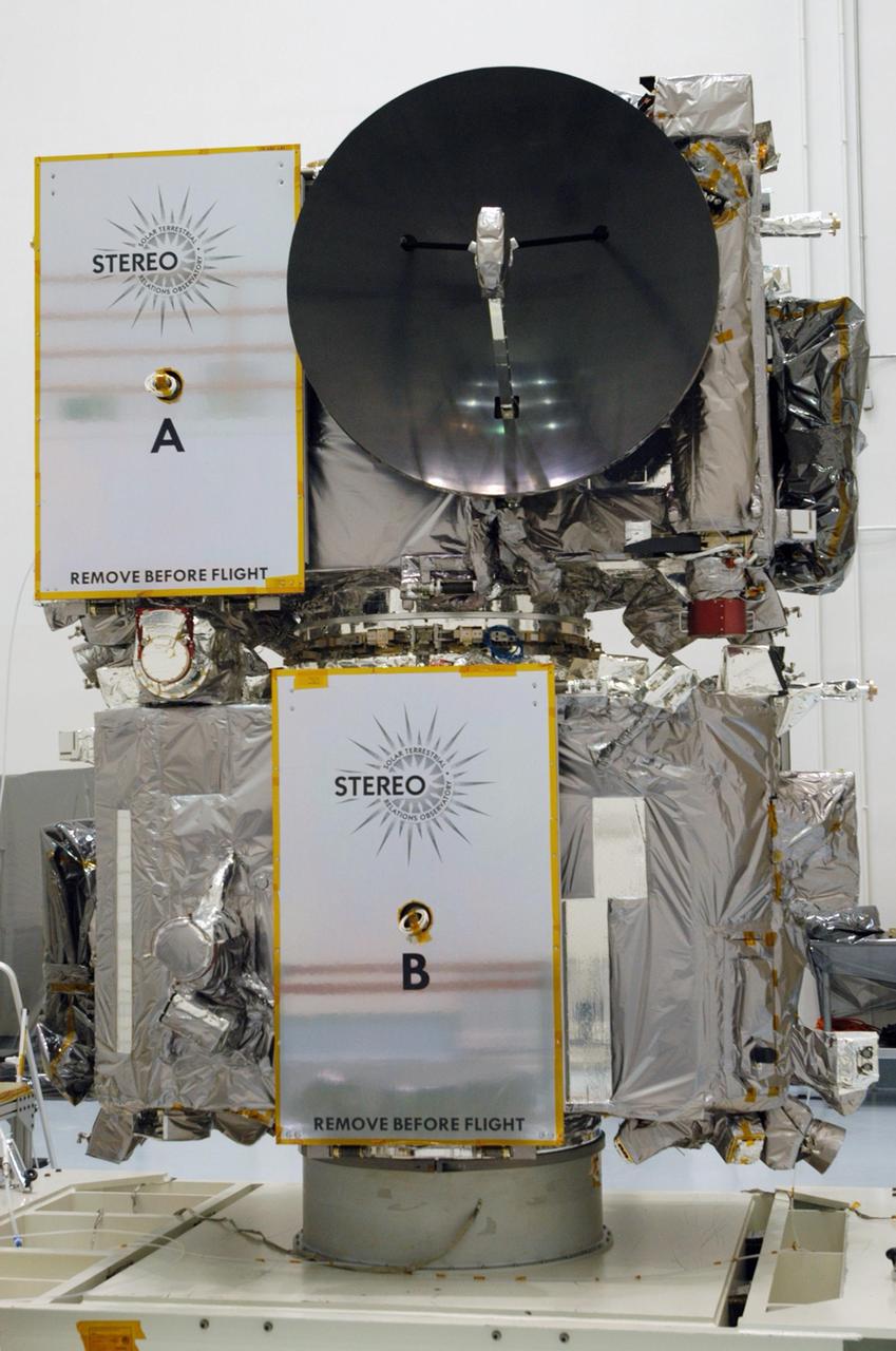
KENNEDY SPACE CENTER, FLA. - The STEREO spacecraft sits on a test stand inside the Astrotech facility in Titusville, Florida. The twin observatories will undergo a spin test to check balance and alignment in preparation for flight. STEREO stands for Solar Terrestrial Relations Observatory. The STEREO mission is the first to take measurements of the sun and solar wind in 3-dimension. This new view will improve our understanding of space weather and its impact on the Earth. STEREO is expected to lift off on Aug. 31, from Launch Pad 17-B on Cape Canaveral Air Force Station in Florida. Photo credit: NASA/George Shelton.
At its founding, the Marshall Space Flight Center (MSFC) inherited the Army’s Jupiter and Redstone test stands, but much larger facilities were needed for the giant stages of the Saturn V. From 1960 to 1964, the existing stands were remodeled and a sizable new test area was developed. The new comprehensive test complex for propulsion and structural dynamics was unique within the nation and the free world, and they remain so today because they were constructed with foresight to meet the future as well as on going needs. Construction of the S-IC Static test stand complex began in 1961 in the west test area of MSFC, and was completed in 1964. The S-IC static test stand was designed to develop and test the 138-ft long and 33-ft diameter Saturn V S-IC first stage, or booster stage, weighing in at 280,000 pounds. Required to hold down the brute force of a 7,500,000-pound thrust produced by 5 F-1 engines, the S-IC static test stand was designed and constructed with the strength of hundreds of tons of steel and 12,000,000 pounds of cement, planted down to bedrock 40 feet below ground level. The foundation walls, constructed with concrete and steel, are 4 feet thick. The base structure consists of four towers with 40-foot-thick walls extending upward 144 feet above ground level. The structure was topped by a crane with a 135-foot boom. With the boom in the upright position, the stand was given an overall height of 405 feet, placing it among the highest structures in Alabama at the time. In addition to the stand itself, related facilities were constructed during this time. Built directly east of the test stand was the Block House, which served as the control center for the test stand. The two were connected by a narrow access tunnel which housed the cables for the controls. Again to the east, just south of the Block House, was a newly constructed Pump House. Its function was to provide water to the stand to prevent melting damage during testing. The water was sprayed through small holes in the stand’s 1900 ton water deflector at the rate of 320,000 gallons per minute. In this photo, taken July 3, 1963, the Pump House is undergoing construction and has reached ground level.

NASA Deputy Administrator Lori Garver and U.S. Rep. Steven Palazzo, R-Miss., view a May 3, 2012, test of the Aerojet AJ26 rocket engine on the E-1 Test Stand at Stennis Space Center. The AJ26 engine is being tested for Orbital Sciences Corporation to power commercial cargo flights to the International Space Station.
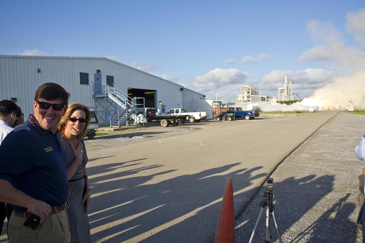
NASA Deputy Administrator Lori Garver and U.S. Rep. Steven Palazzo, R-Miss., view a May 3, 2012, test of the Aerojet AJ26 rocket engine on the E-1 Test Stand at Stennis Space Center. The AJ26 engine is being tested for Orbital Sciences Corporation to power commercial cargo flights to the International Space Station.

Instructor Rob Mortin watches as Stennis Space Center firefighters Lt. Greg Lampley, Rodney Boone, Vance Forrest and Billy Scarborough practice high-angle rope rescue techniques during a May 11, 2012, training exercise. The exercise specifically focused on scenarios applicable to the 300-foot-tall, open-steel-structure A-3 Test Stand under construction at the rocket engine test facility.
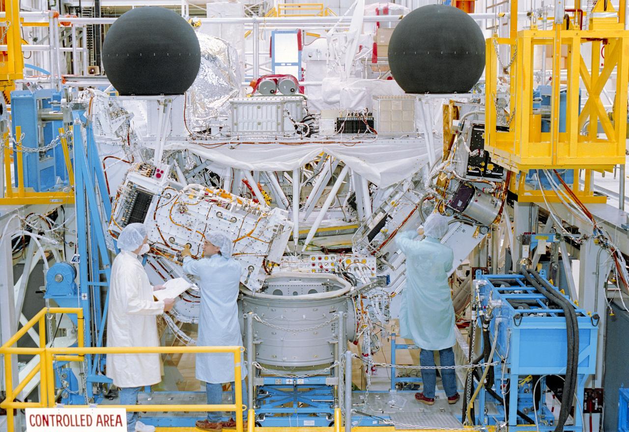
S92-27865 (23 Sept 1991) --- In test stand 3 of the Operations and Checkout Building high bay, workers complete mating of the Atmosphere Laboratory for Applications and Science-1 (ATLAS-1) pallet and Igloo power unit. Closeout activities on the ATLAS-1 payload are under way, with a systems test scheduled for later in October. The ATLAS series of missions will study solar and atmospheric physics. ATLAS-1 is scheduled to fly on Space Shuttle Mission STS-45 in 1992.
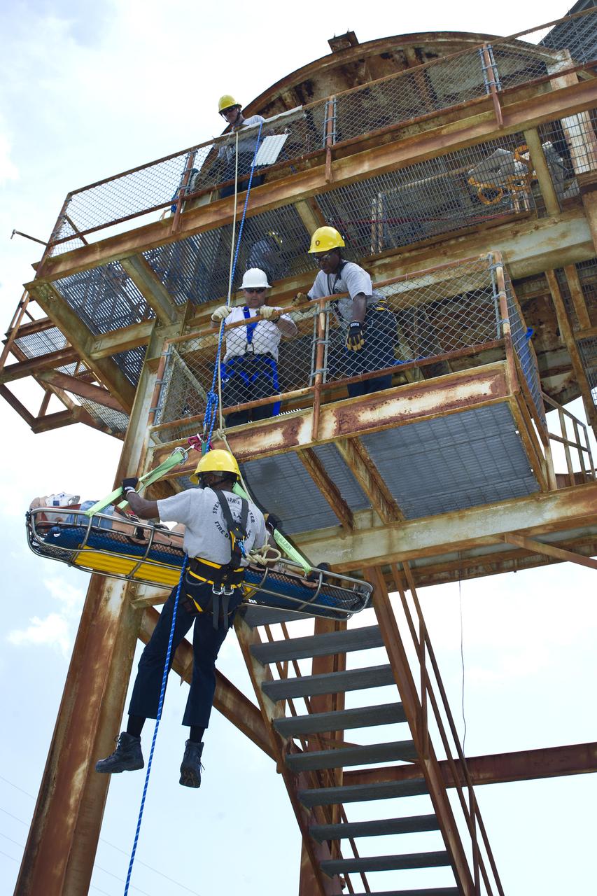
Instructor Rob Mortin watches as Stennis Space Center firefighters Lt. Greg Lampley, Rodney Boone, Vance Forrest and Billy Scarborough practice high-angle rope rescue techniques during a May 11, 2012, training exercise. The exercise specifically focused on scenarios applicable to the 300-foot-tall, open-steel-structure A-3 Test Stand under construction at the rocket engine test facility.

CAPE CANAVERAL, Fla. – The Ares I-X rocket stands tall inside NASA Kennedy Space Center's Vehicle Assembly Building Bay 3. Part of the Constellation Program, the Ares I-X is the test vehicle for the Ares I, which is the essential core of a space transportation system that eventually will carry crewed missions back to the moon, on to Mars and out into the solar system . The Ares I-X flight test is targeted for Oct. 27. Photo credit: NASA/Kim Shiflett

NASA Administrator Charles Bolden (r) discusses the upcoming testing of Blue Origin's BE-3 engine thrust chamber assembly with Steve Knowles, Blue Origin project manager, at the E-1 Test Stand during an April 20, 2012, visit to Stennis Space Center. Blue Origin is one of NASA's partners developing innovative systems to reach low-Earth orbit.
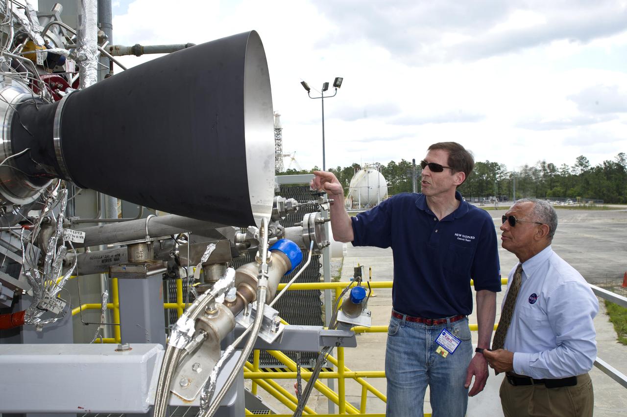
NASA Administrator Charles Bolden (r) discusses the upcoming testing of Blue Origin's BE-3 engine thrust chamber assembly with Steve Knowles, Blue Origin project manager, at the E-1 Test Stand during an April 20, 2012, visit to Stennis Space Center. Blue Origin is one of NASA's partners developing innovative systems to reach low-Earth orbit.
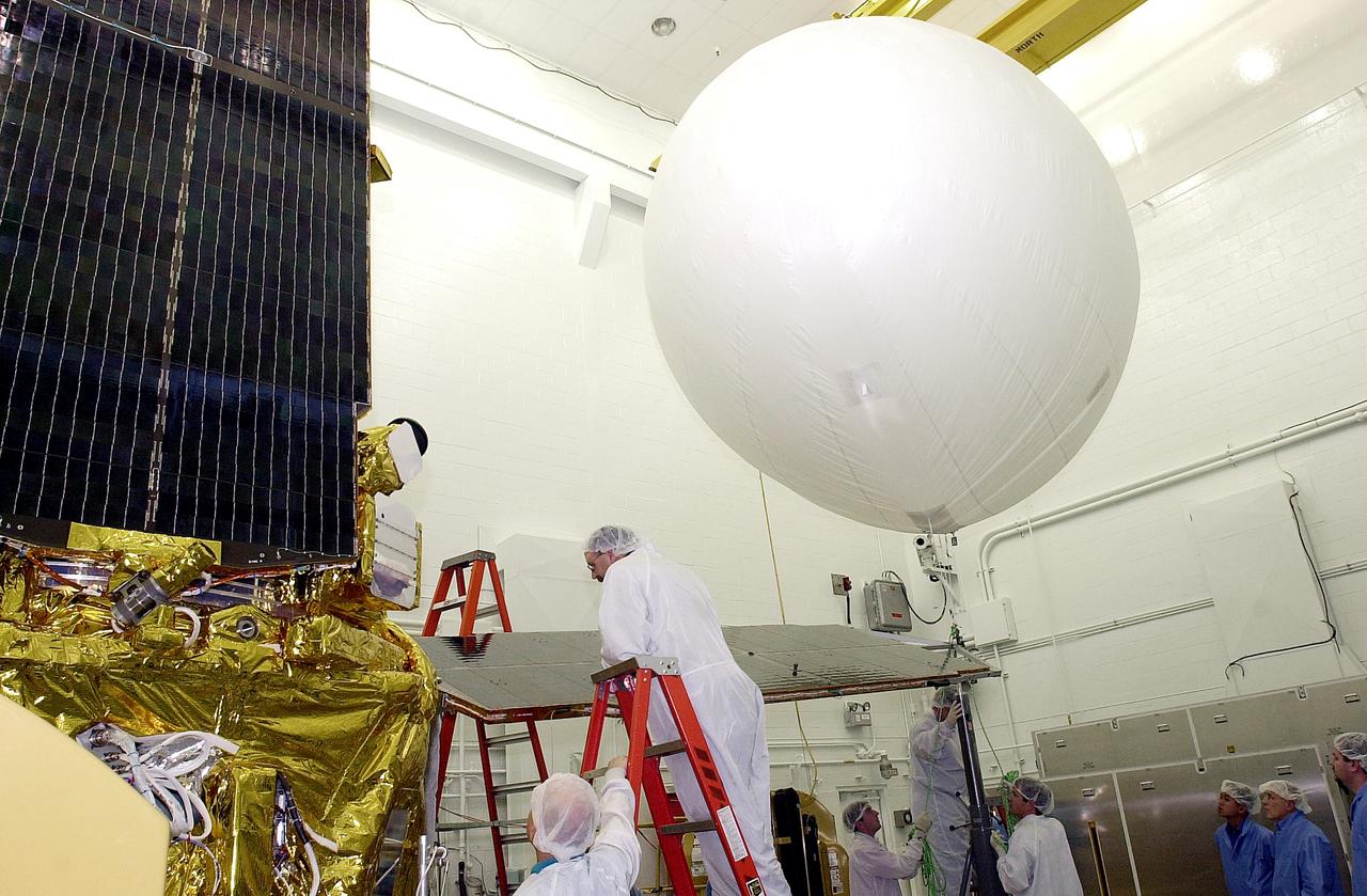
VANDENBERG AFB, CALIF. - In the NASA spacecraft processing facility on North Vandenberg Air Force Base, workers stand by as the balloon at right is released to lift the solar array panel into position for installation on the Gravity Probe B spacecraft. Installing each array is a 3-day process and includes a functional deployment test. The Gravity Probe B mission is a relativity experiment developed by NASA’s Marshall Space Flight Center, Stanford University and Lockheed Martin. The spacecraft will test two extraordinary predictions of Albert Einstein’s general theory of relativity that he advanced in 1916: the geodetic effect (how space and time are warped by the presence of the Earth) and frame dragging (how Earth’s rotation drags space and time around with it). Gravity Probe B consists of four sophisticated gyroscopes that will provide an almost perfect space-time reference system. The mission will look in a precision manner for tiny changes in the direction of spin.
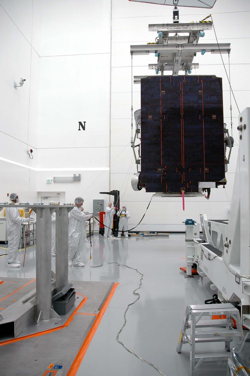
KENNEDY SPACE CENTER, FLA. - At Astrotech in Titusville, Fla., the overhead crane moves the GOES-N satellite away from the rotation stand for transfer to a work stand. Since its arrival on March 11, the satellite has been undergoing final testing by Boeing Satellite Systems of the imaging system, instrumentation, communications and power systems. Geostationary Operational Environmental Satellites (GOES) are sponsored by NASA’s Goddard Space Flight Center and the National Oceanic and Atmospheric Administration. GOES-N is targeted to launch May 4 onboard a Boeing expendable launch vehicle Delta IV (4,2) with a 3-burn second stage operation.

KENNEDY SPACE CENTER, FLA. -- Node 1, the first U.S. element for the International Space Station, and attached Pressurized Mating Adapter-1 (PMA-1) continue with prelaunch preparation activities at KSC's Space Station Processing Facility. Node 1 is a connecting passageway to the living and working areas of the space station. The node and PMA-1 are being removed from the element rotation stand, or test stand, where they underwent an interim weight and center of gravity determination. (The final determination is planned to be performed prior to transporting Node 1 to the launch pad.) Now the node is being moved to the Shuttle payload transportation canister, where the doors will be closed for a two-week leak check. PMAs -2 and -3 can be seen against the right wall, with PMA-3 at the far right. Node 1 is scheduled to fly on STS-88