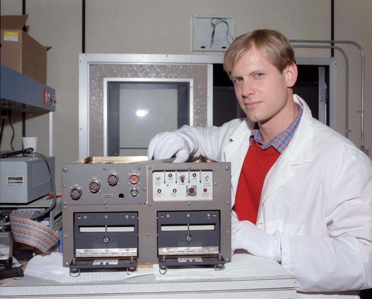
Space Acceleration Measurement System, SAMS Flight Hardware, Unit A
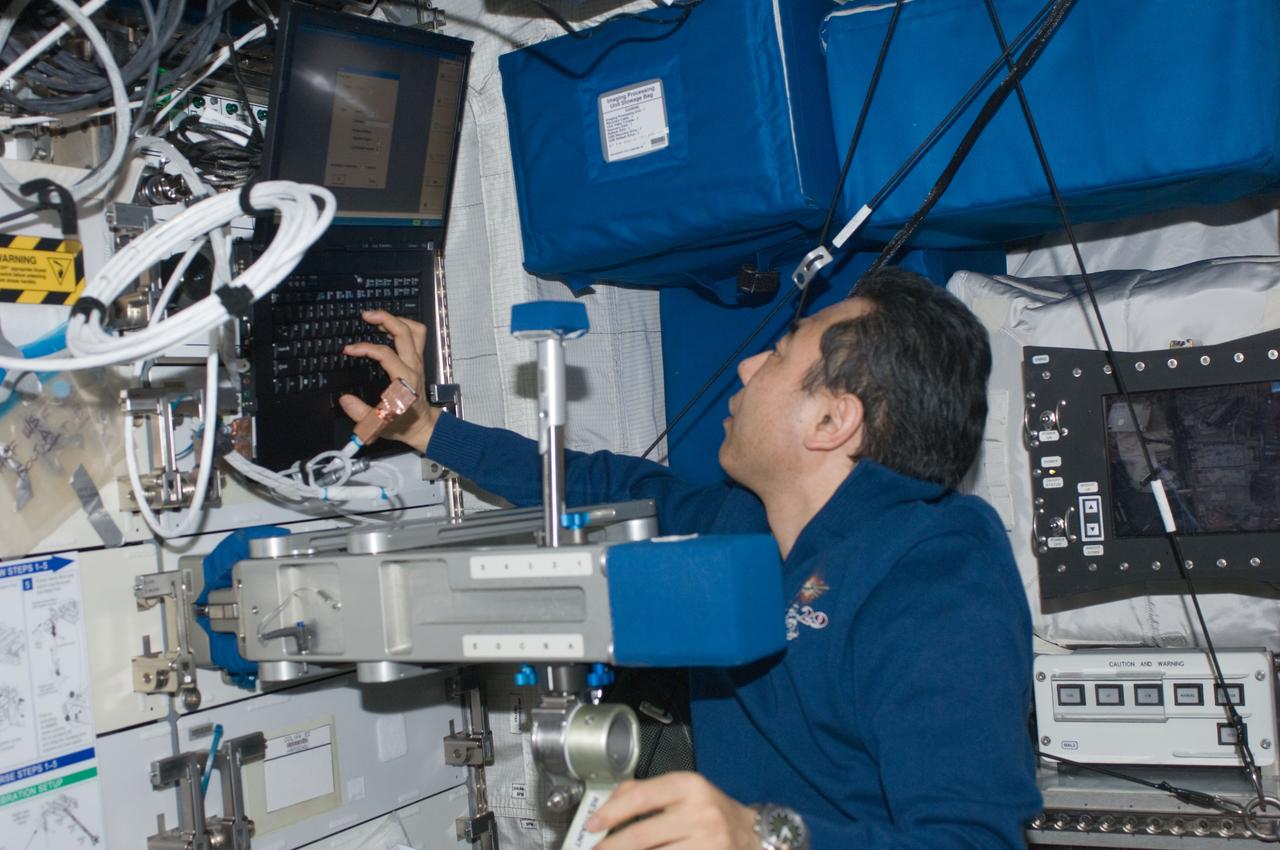
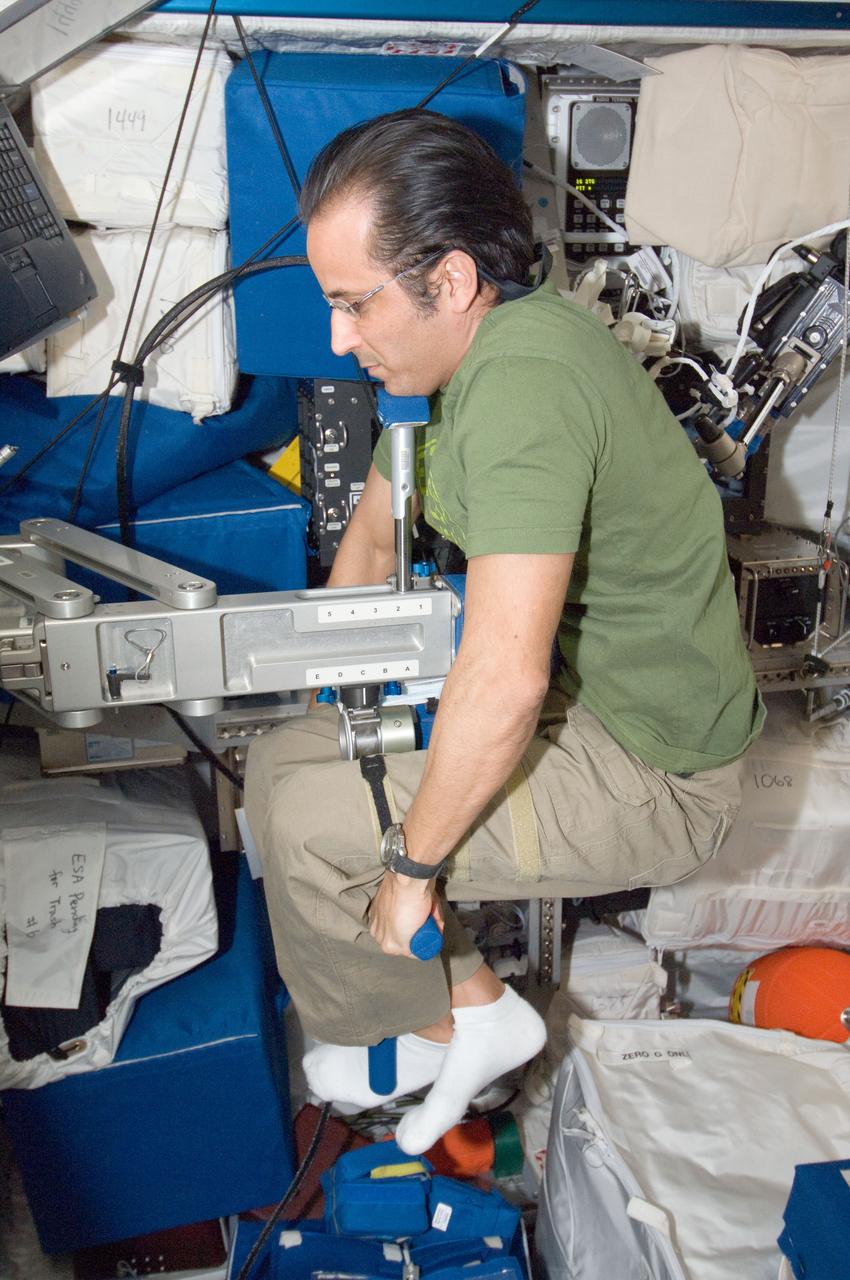
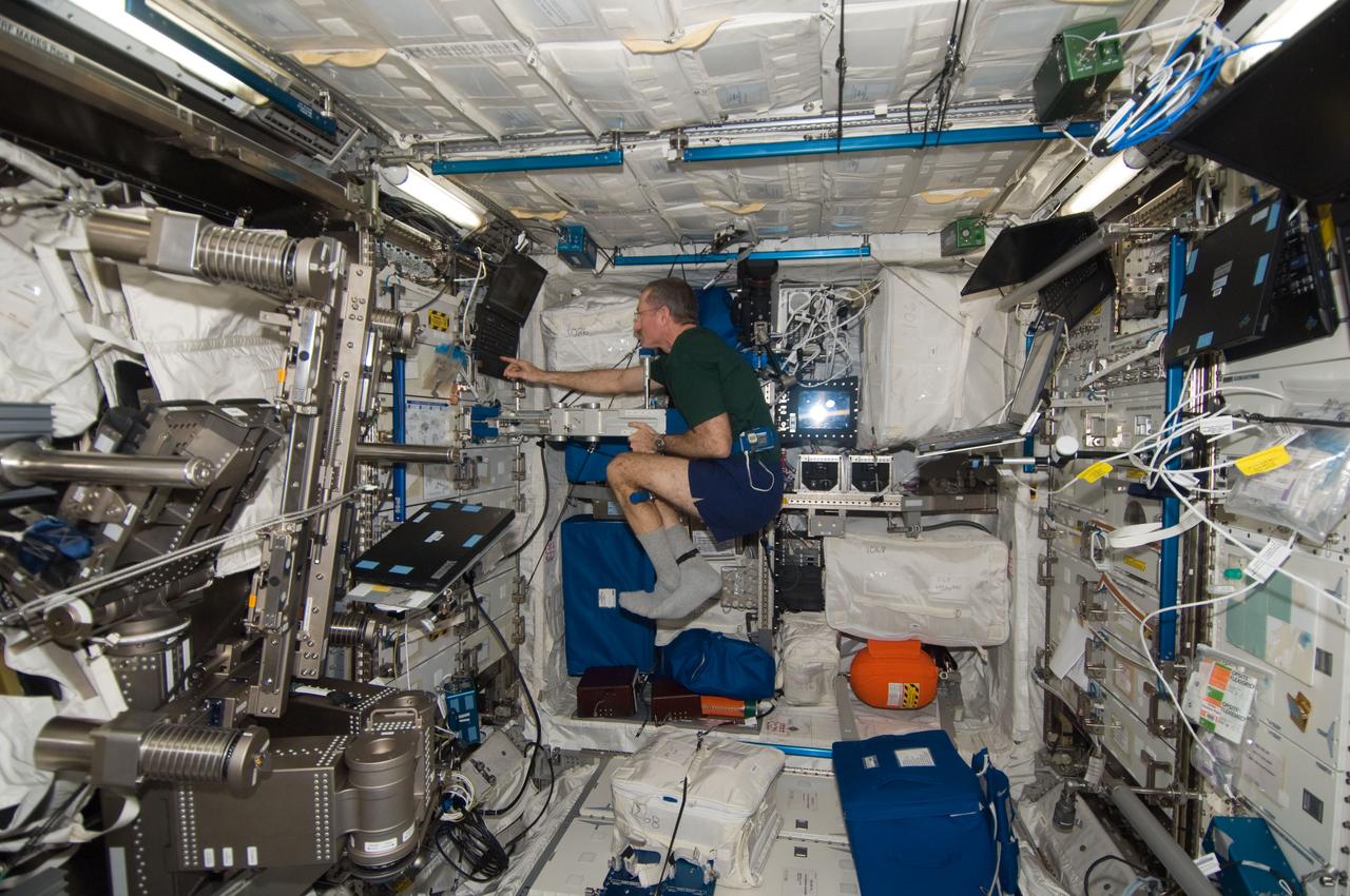
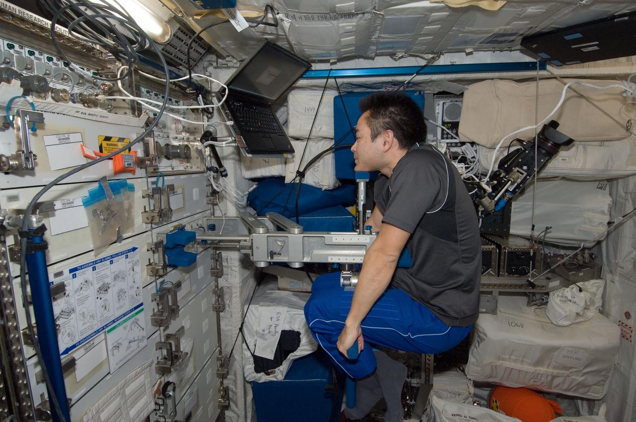
ISS029-E-017480 (5 Oct. 2011) --- Japan Aerospace Exploration Agency astronaut Satoshi Furukawa, Expedition 29 flight engineer, uses the Space Linear Acceleration Mass Measurement Device (SLAMMD) in the Columbus laboratory of the International Space Station.
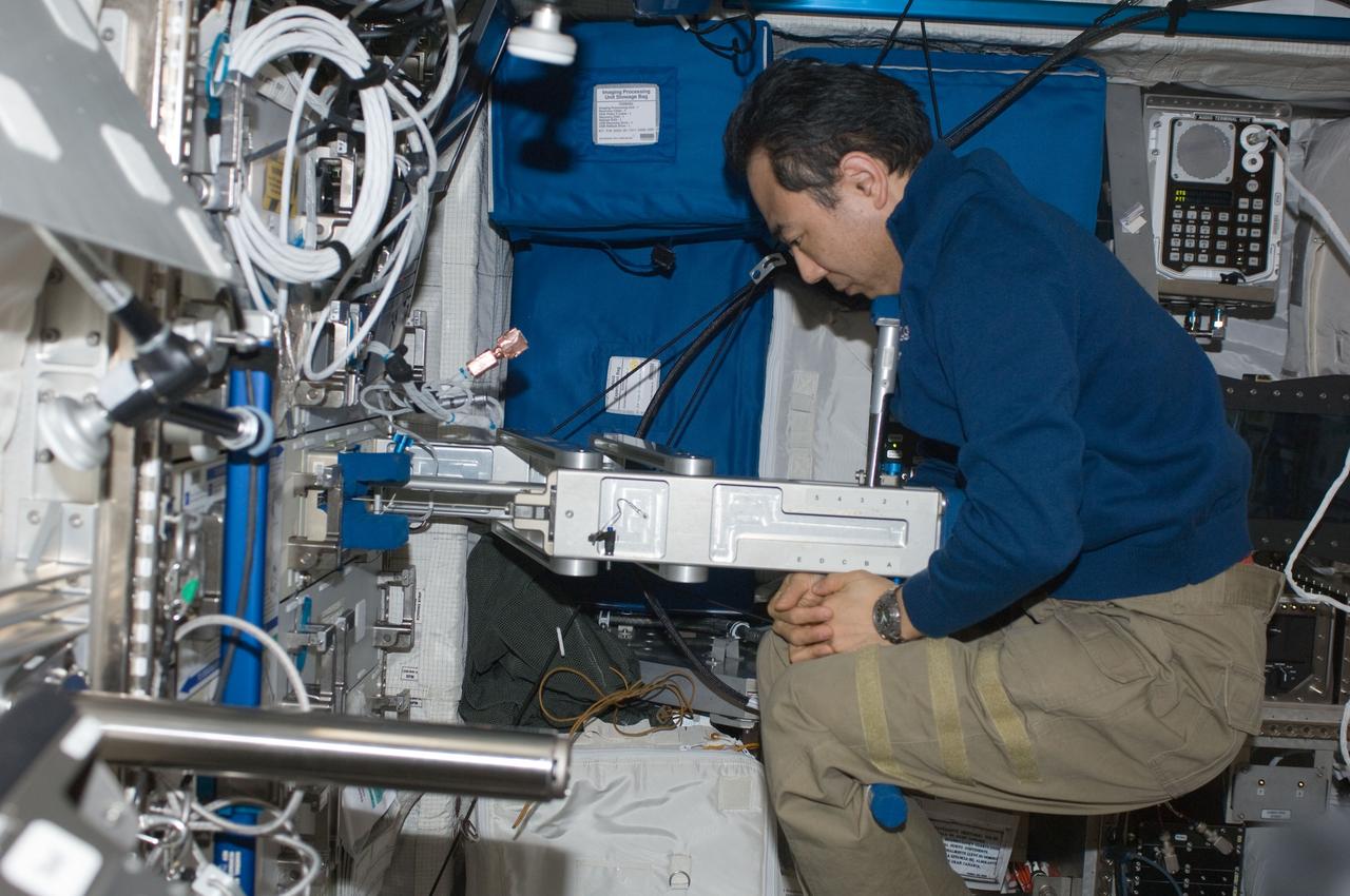
ISS029-E-017474 (5 Oct. 2011) --- Japan Aerospace Exploration Agency astronaut Satoshi Furukawa, Expedition 29 flight engineer, prepares to use the Space Linear Acceleration Mass Measurement Device (SLAMMD) in the Columbus laboratory of the International Space Station.
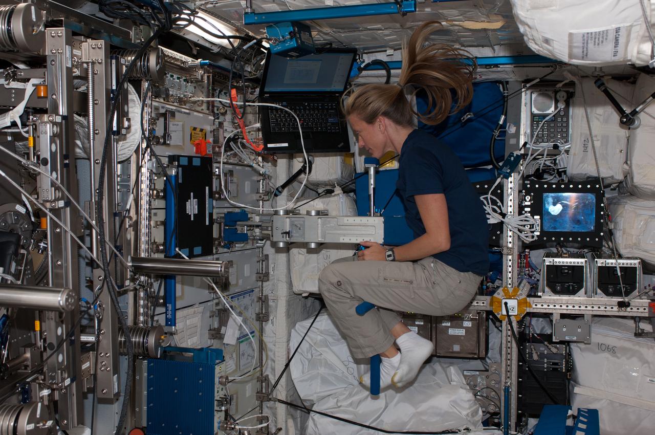
Astronaut Karen Nyberg,Expedition 36 flight engineer,performs a Space Linear Acceleration Mass Measurement Device (SLAMMD) Body Mass Measurement test in the U.S. Laboratory.
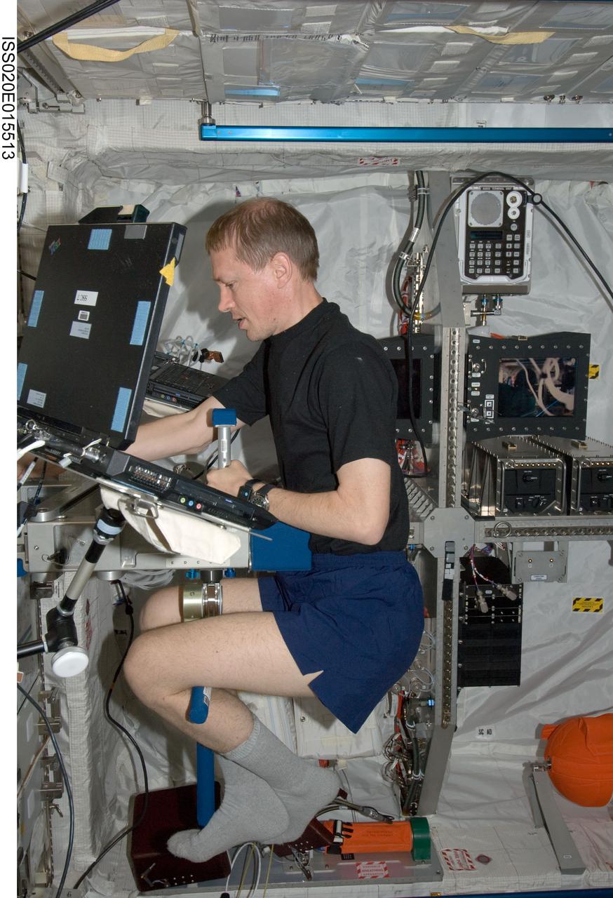
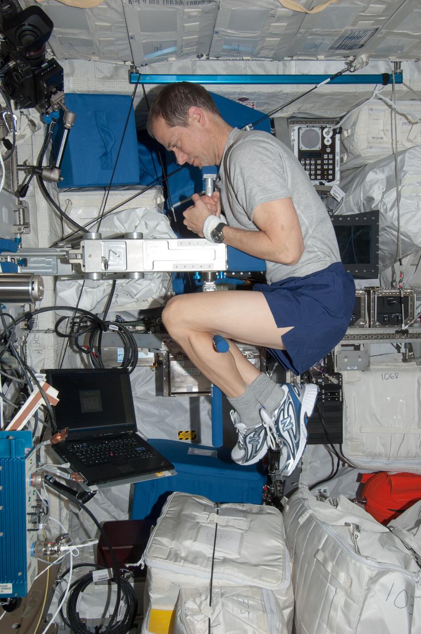
ISS020-E-015513 (29 June 2009) --- European Space Agency astronaut Frank De Winne, Expedition 20 flight engineer, works with the Space Linear Acceleration Mass Measurement Device (SLAMMD) in the Columbus laboratory of the International Space Station.
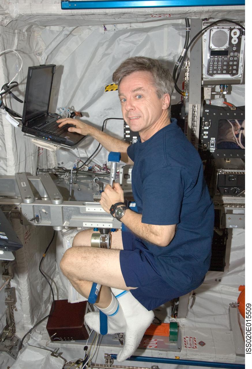
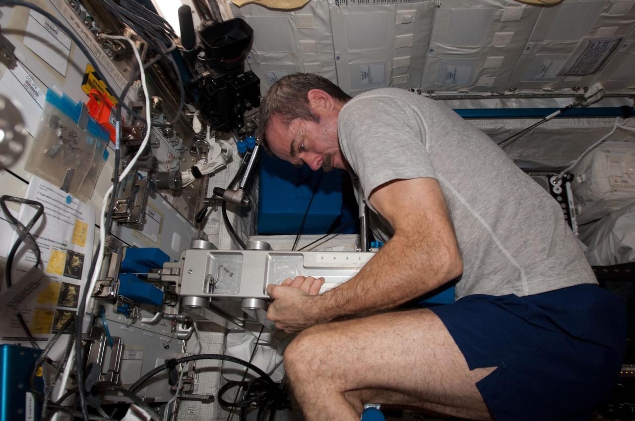
ISS020-E-015509 (29 June 2009) --- Canadian Space Agency astronaut Robert Thirsk, Expedition 20 flight engineer, works with the Space Linear Acceleration Mass Measurement Device (SLAMMD) in the Columbus laboratory of the International Space Station.
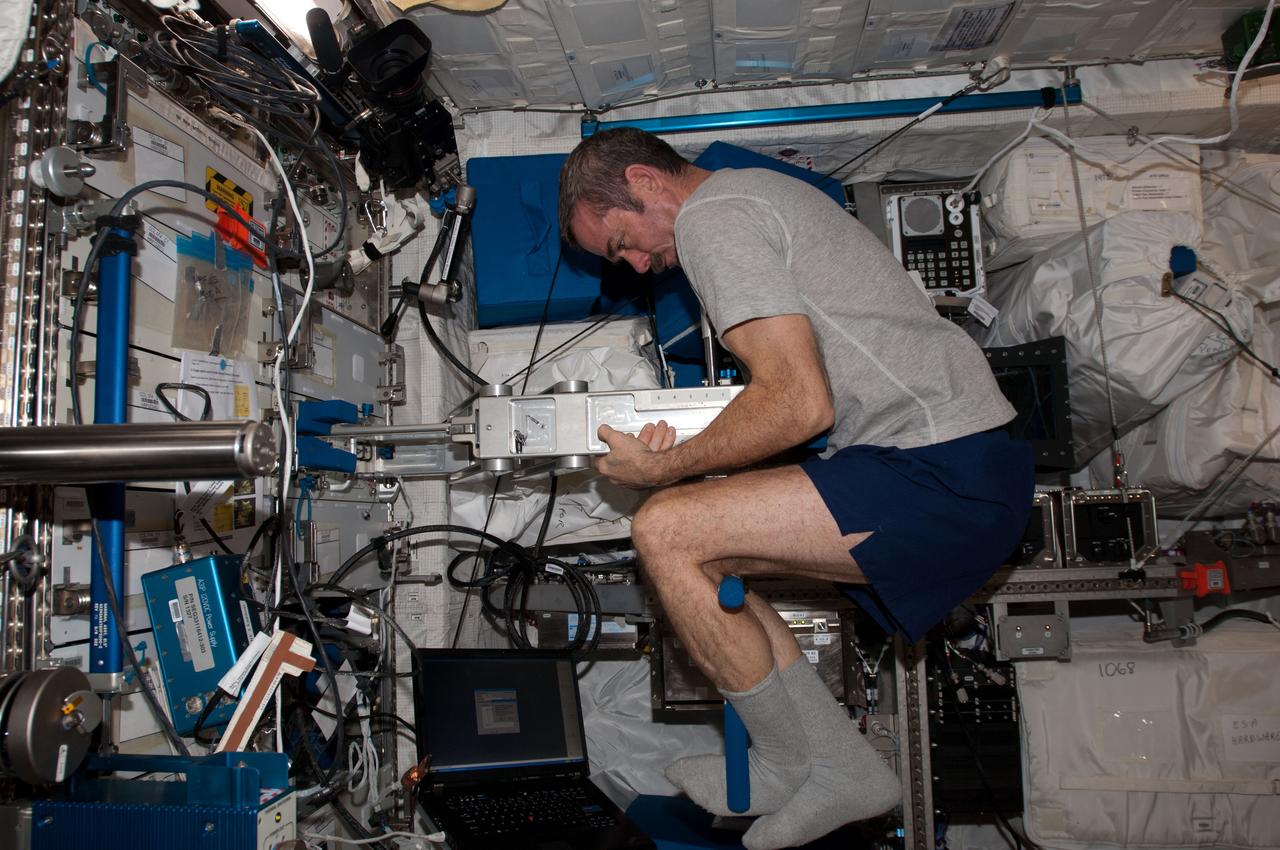
View of Canadian Space Agency (CSA) Chris Hadfield, Expedition 34 Flight Engineer (FE), using the Space Linear Acceleration Mass Measurement Device (SLAMMD) in the Columbus Module. Photo was taken during Expedition 34.
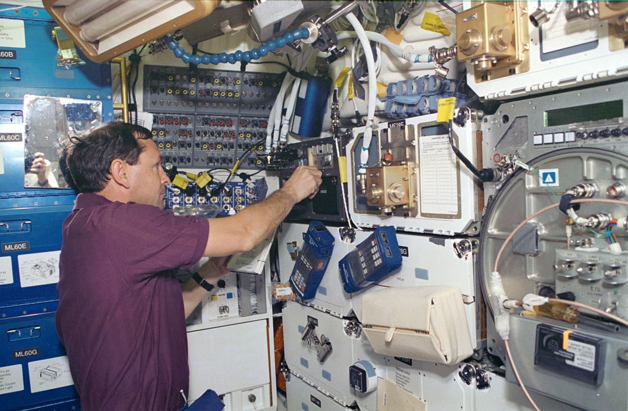
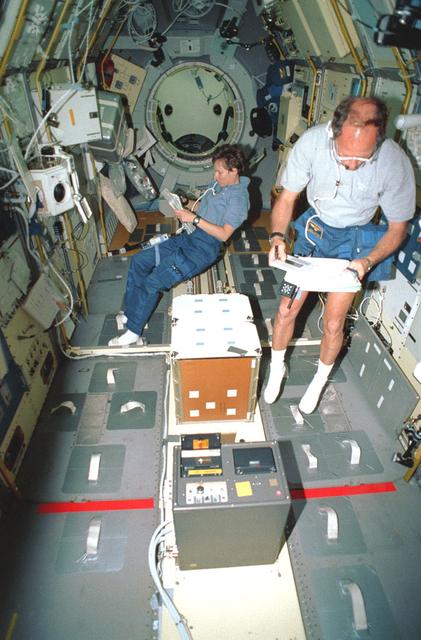
STS066-14-021 (3-14 Nov 1994) --- On the Space Shuttle Atlantis' mid-deck, astronaut Curtis L. Brown, Jr., pilot, works with the Space Acceleration Measurement System (SAMS), which is making its eleventh Shuttle flight. This system supports the Protein Crystal Growth (PCG) experiments onboard by collecting and recording data characterizing the microgravity environment in the Shuttle mid-deck. Brown joined four other NASA astronauts and a European Space Agency (ESA) astronaut for 11-days aboard Atlantis in support of the Atmospheric Laboratory for Applications and Science (ATLAS-3) mission.
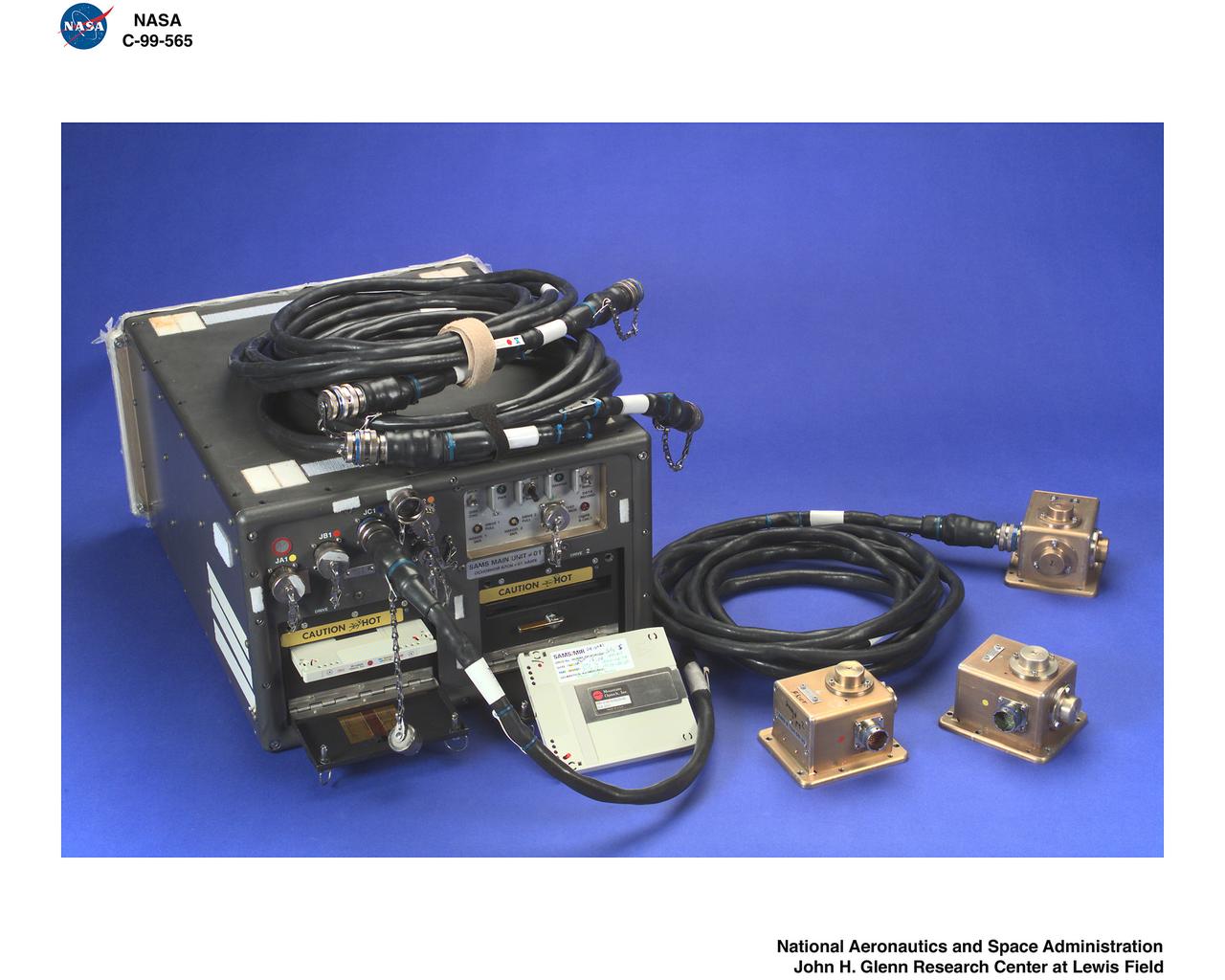
SPACE ACCELERATION MEASUREMENT SYSTEM SAMS HARDWARE AND RELATED MATERIALS

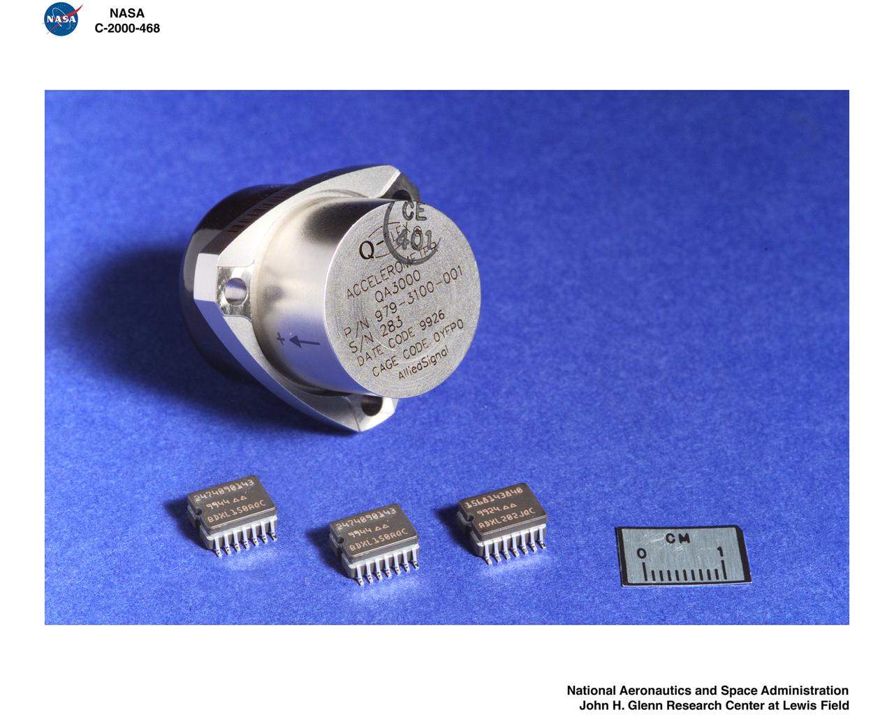
ADVANCED MICROGRAVITY ACCELERATION MEASUREMENT SYSTEMS - MEMS - US ELECTRO MECHANICAL
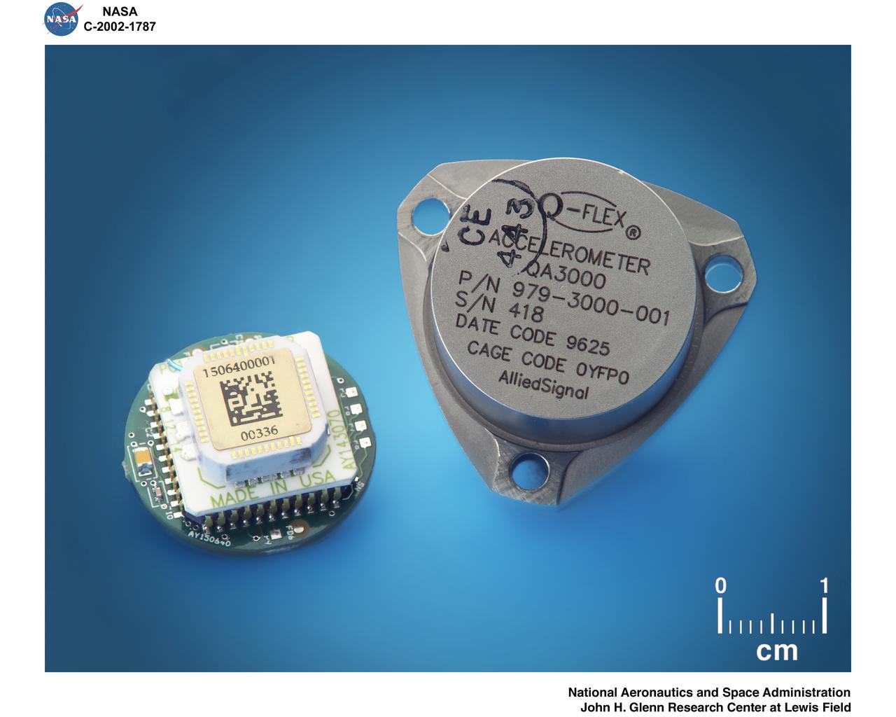
ADVANCED MICROGRAVITY ACCELERATION MEASUREMENT SYSTEMS - MEMS - US ELECTRO MECHANICAL
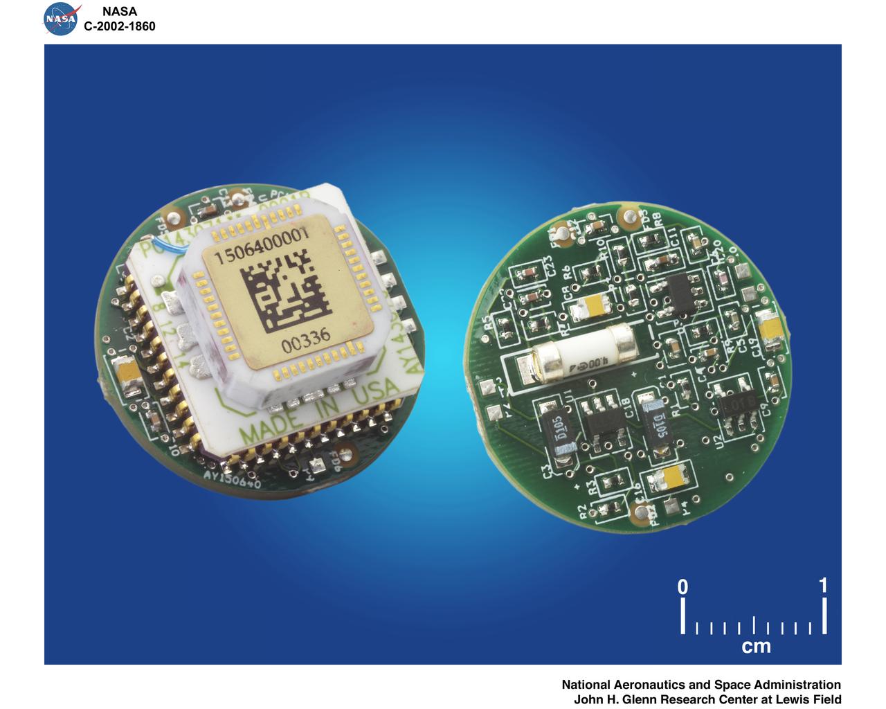
ADVANCED MICROGRAVITY ACCELERATION MEASUREMENT SYSTEM - MEMS - US ELECTRO MECHANICAL
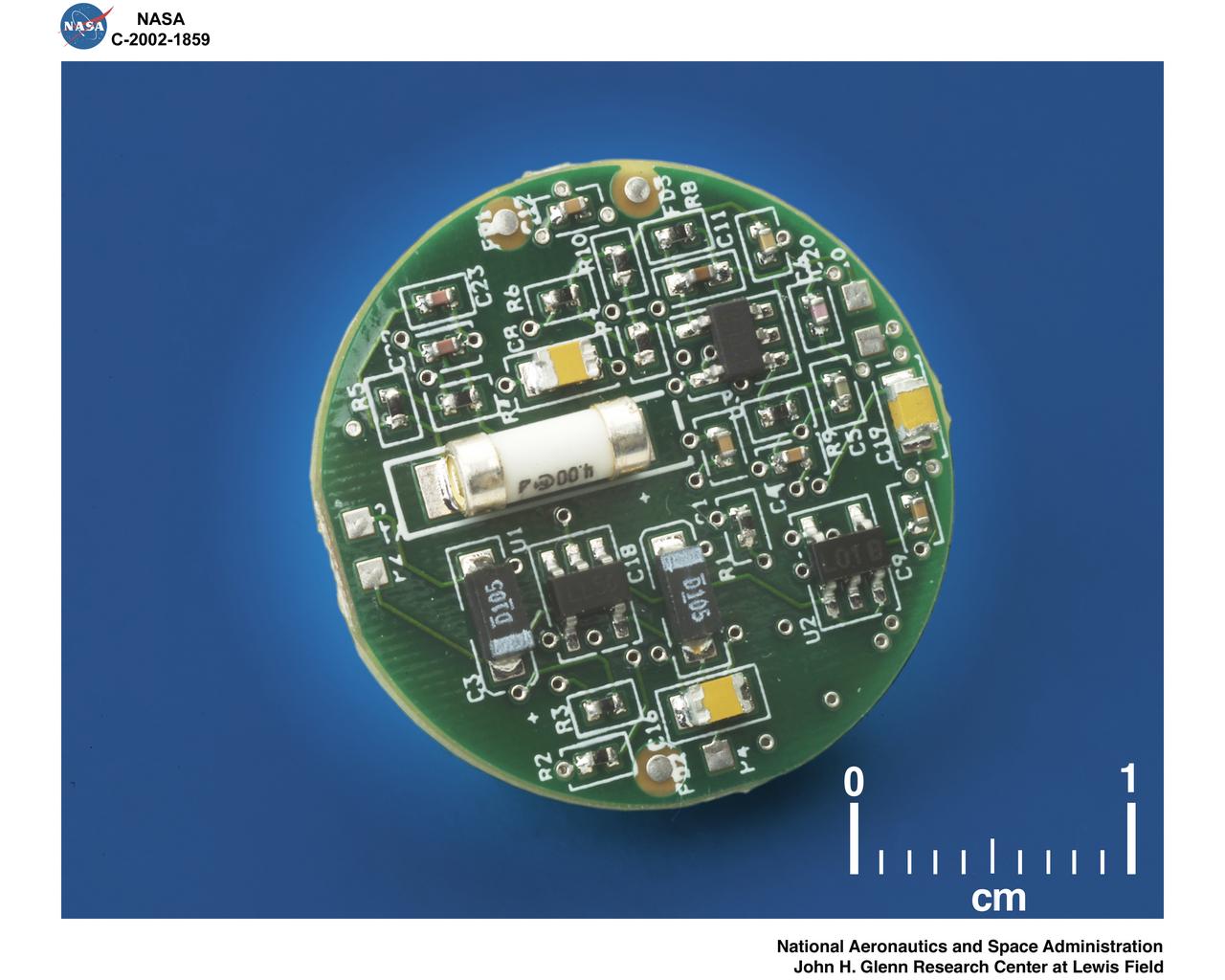
ADVANCED MICROGRAVITY ACCELERATION MEASUREMENT SYSTEM - MEMS - US ELECTRO MECHANICAL
NASA HEADQUARTERS CODE R PRESENTATION - SPACE ACCELERATION AND MEASUREMENT SYSTEM SAMS MICRO ELECTRONIC MACHINE SENSOR
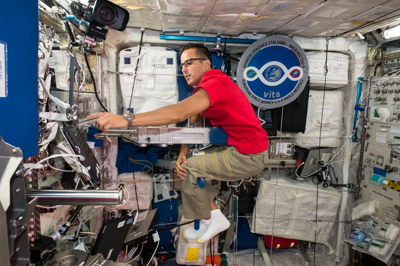
iss053e059889 (Sept. 28, 2017) --- Astronaut Joe Acaba calculates his mass inside the Columbus laboratory module using the Space Linear Acceleration Mass Measurement Device (SLAMMD). The device generates a known force against a crew member mounted on an extension arm with the resulting acceleration used to calculate the subject’s mass.
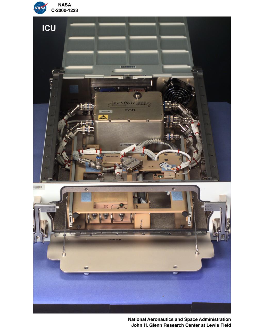
SPACE ACCELERATION MEASUREMENT SYSTEM 2 - SAMS 2 - FLIGHT HARDWARE - ICU - INTERIM CONTROL UNIT - RTS - REMOTE TRIAXIAL SENSOR DRAWERS
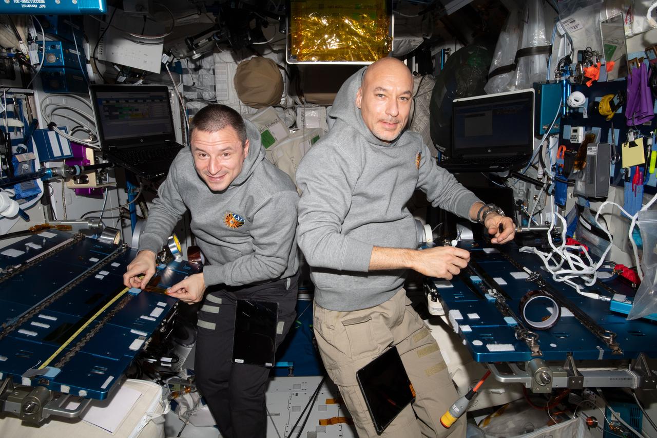
iss061e021362 (Oct. 30, 2019) --- From left, NASA Flight Engineer Andrew Morgan and Commander Luca Parmitano of ESA (European Space Agency) set up a work space in the Columbus laboratory module. Parmitano would soon test a device in Columbus that measures an astronaut’s mass using Newton’s Second Law of Motion. The device, named the Space Linear Acceleration Mass Measurement Device, applies a known force to an attached astronaut and the resulting acceleration is used to calculate an astronaut’s mass.
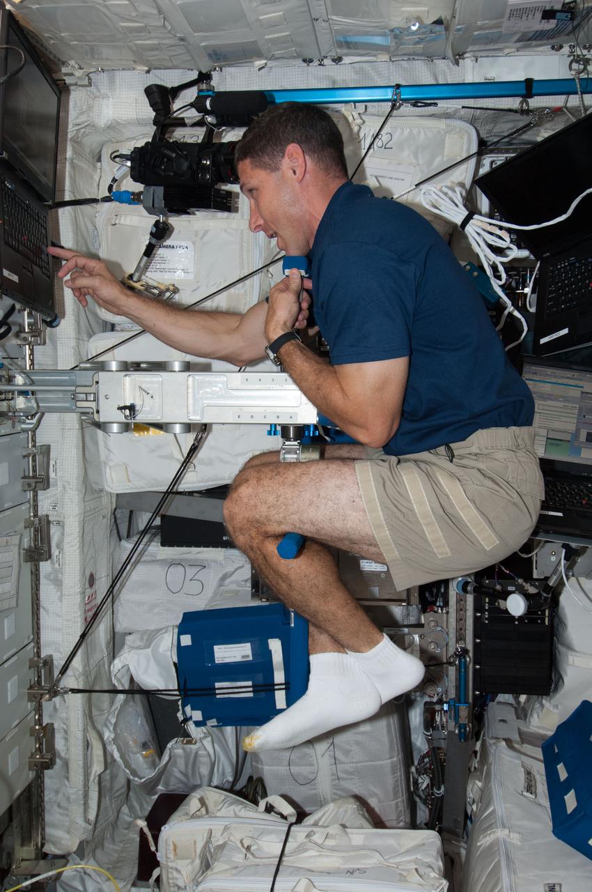
ISS037-E-006478 (3 Oct. 2013) --- NASA astronaut Michael Hopkins, Expedition 37 flight engineer, performs Body Mass Measurement activities using the Space Linear Acceleration Mass Measurement Device (SLAMMD) in the Columbus laboratory aboard the Earth-orbiting International Space Station.
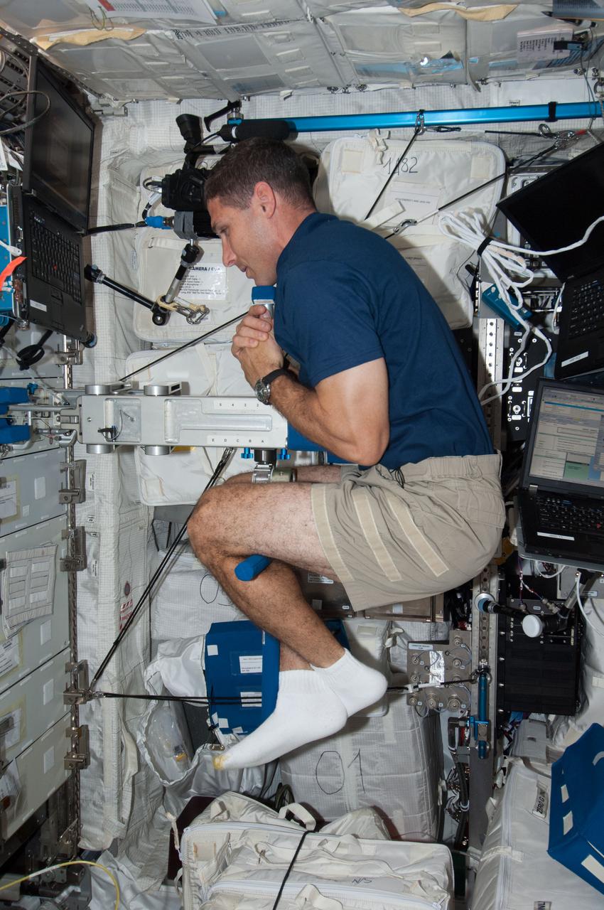
ISS037-E-006475 (3 Oct. 2013) --- NASA astronaut Michael Hopkins, Expedition 37 flight engineer, performs Body Mass Measurement activities using the Space Linear Acceleration Mass Measurement Device (SLAMMD) in the Columbus laboratory aboard the Earth-orbiting International Space Station.
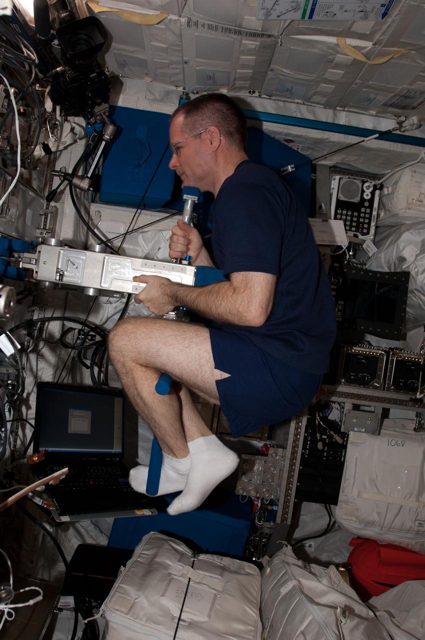
ISS034-E-026569 (11 Jan. 2013) --- NASA astronaut Kevin Ford, Expedition 34 commander, uses the Space Linear Acceleration Mass Measurement Device (SLAMMD) in the Columbus laboratory of the International Space Station.
ISS032-E-024289 (26 Aug. 2012) --- NASA astronaut Joe Acaba, Expedition 32 flight engineer, uses the Space Linear Acceleration Mass Measurement Device (SLAMMD) in the Columbus laboratory of the International Space Station.
ISS030-E-117437 (1 Feb. 2012) --- NASA astronaut Dan Burbank, Expedition 30 commander, uses the Space Linear Acceleration Mass Measurement Device (SLAMMD) in the Columbus laboratory of the International Space Station.
ISS034-E-026654 (11 Jan. 2013) --- NASA astronaut Tom Marshburn, Expedition 34 flight engineer, uses the Space Linear Acceleration Mass Measurement Device (SLAMMD) in the Columbus laboratory of the International Space Station.
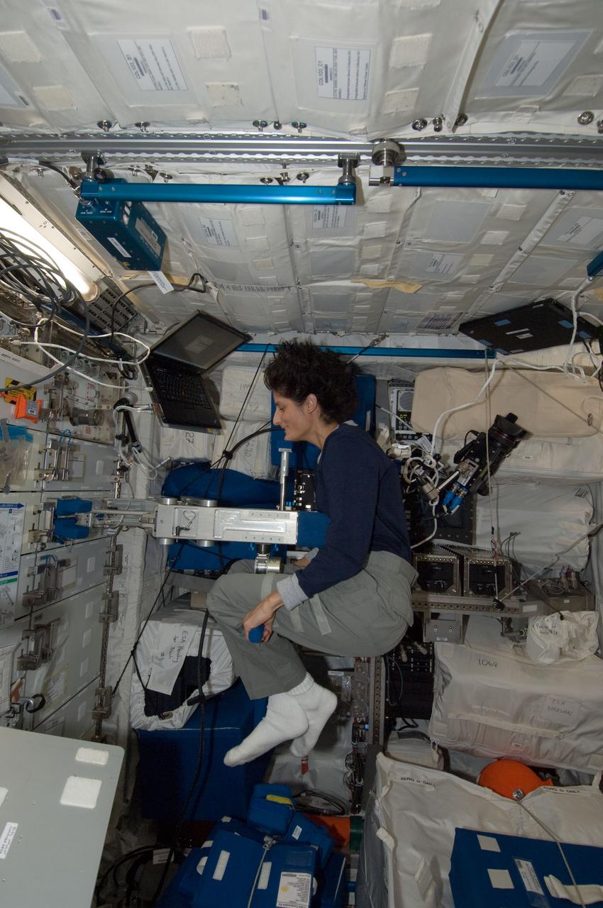
ISS032-E-024285 (26 Aug. 2012) --- NASA astronaut Sunita Williams, Expedition 32 flight engineer, uses the Space Linear Acceleration Mass Measurement Device (SLAMMD) in the Columbus laboratory of the International Space Station.
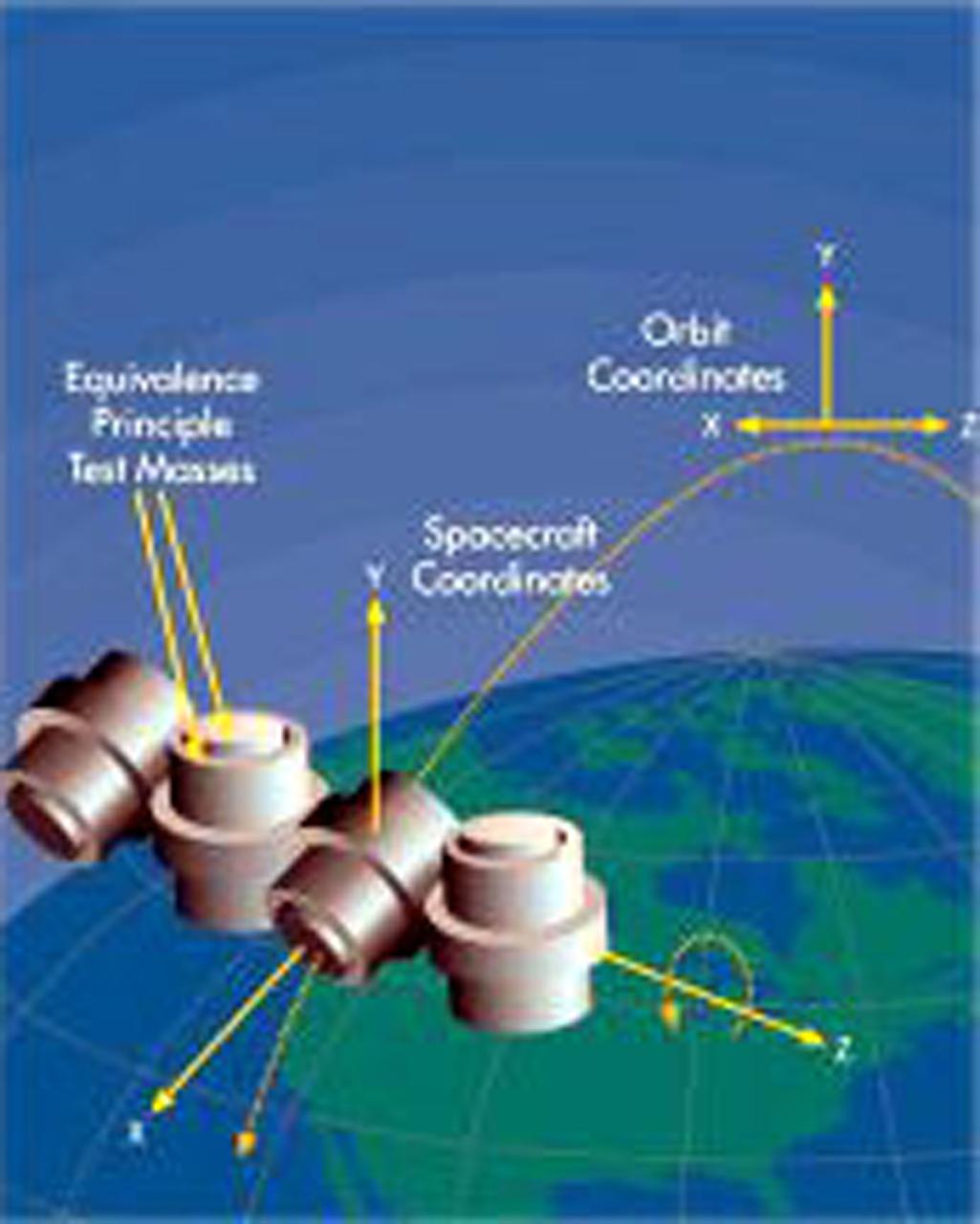
STEP will carry concentric test masses to Earth orbit to test a fundamental assumption underlying Einstein's theory of general relativity: that gravitational mass is equivalent to inertial mass. STEP is a 21st-century version of the test that Galileo is said to have performed by dropping a carnon ball and a musket ball simultaneously from the top of the Leaning Tower of Pisa to compare their accelerations. During the STEP experiment, four pairs of test masses will be falling around the Earth, and their accelerations will be measured by superconducting quantum interference devices (SQUIDS). The extended time sensitivity of the instruments will allow the measurements to be a million times more accurate than those made in modern ground-based tests.
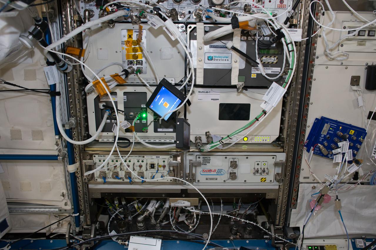
iss050e033362 (1/18/2017) -- A view of Space Acceleration Measurement System-II (SAMS-II), an ongoing study of the small forces (vibrations and accelerations) on the International Space Station (ISS) resulting from the operation of hardware, crew activities, dockings and maneuvering. Results generalize the types of vibrations affecting vibration-sensitive experiments and structural life of ISS. Investigators and Structural Analysts seek to better understand the vibration environment on the ISS using SAMS-II data and assessing station loads and dynamics.

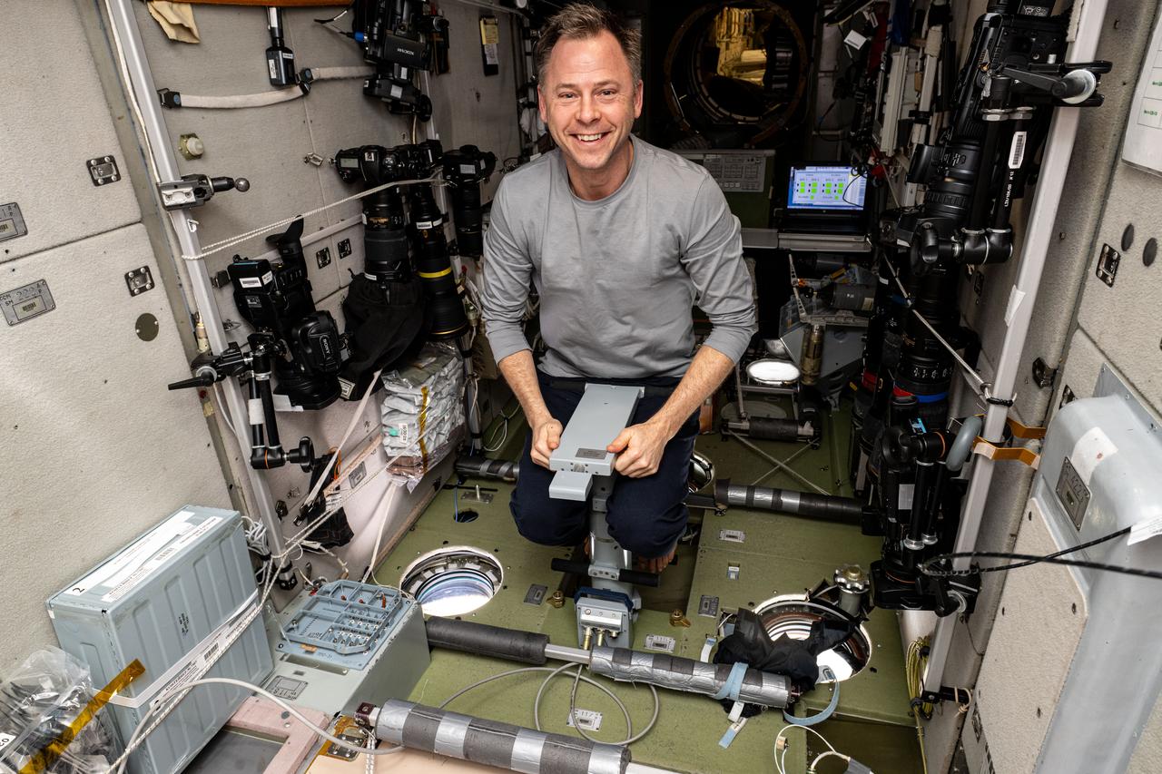
iss071e113128 (May 22, 2024) --- Expedition 71 Flight Engineer and NASA astronaut Matthew Dominick works in the International Space Station's Columbus laboratory module performing maintenance on the Space Linear Acceleration Mass Measurement Device, or SLAMMD. The human research device applies a known force to a crew member then calculates body mass using a form of Newton’s Second Law of Motion, force equals mass times acceleration.
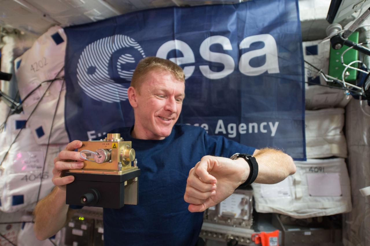
ISS046e024411 (01/26/2016) --- European Space Agency (ESA) astronaut Timothy Peake prepares to install a space acceleration measurement system sensor inside the European Columbus module aboard the International Space Station. The device is used in an ongoing study of the small forces (vibrations and accelerations) on the International Space Station resulting from the operation of hardware, crew activities, dockings and maneuvering. Results generalize the types of vibrations affecting vibration-sensitive experiments.
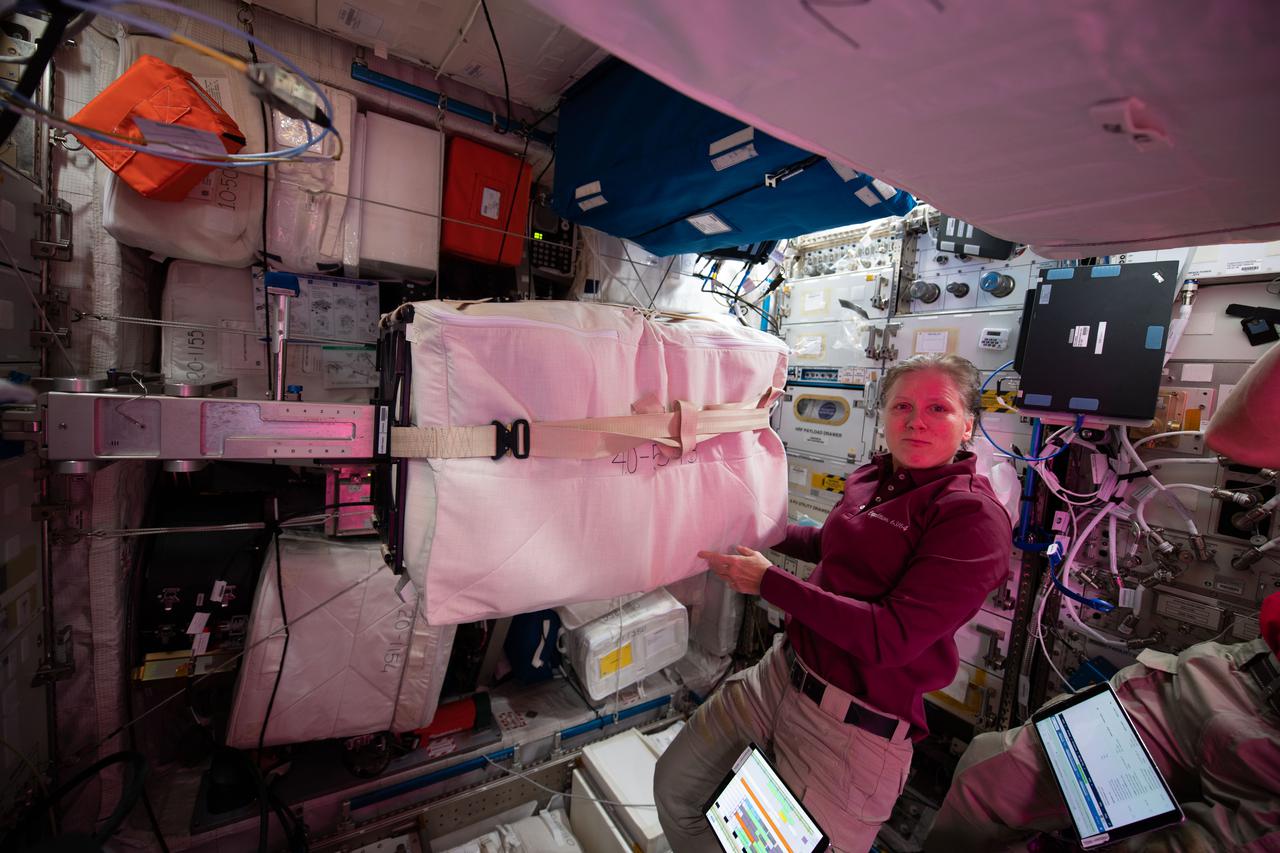
iss064e019119 (Jan. 4, 2021) --- NASA astronaut and Expedition 64 Flight Engineer Shannon Walker works in the European Columbus laboratory module to set up a unique device that calculates the mass of cargo aboard the International Space Station. Known as SLAMMD, or Space Linear Acceleration Mass Measurement Device, it uses a form of Newton's Second Law of Motion and applies a known force to an object or an astronaut with the resulting acceleration used to calculate mass in microgravity
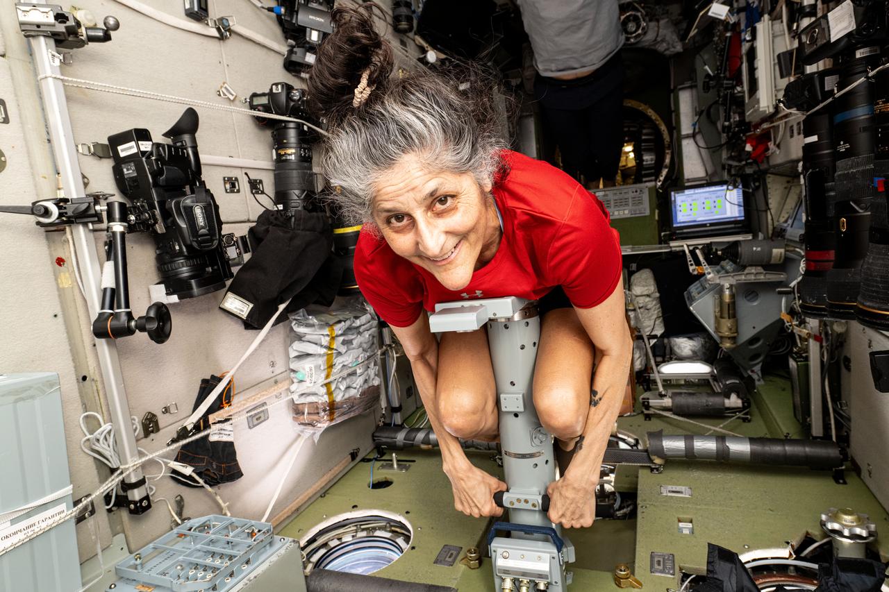
iss072e616384 (Feb. 11, 2025) --- NASA astronaut and Expedition 72 Commander Suni Williams measures her mass using a specialized device inside the International Space Station's Zvezda service module. The mass measurement device applies a known force to an attached astronaut and measures the resulting acceleration to acquire the crew member's mass. The result is based on a form of Newton's Second Law of Motion.
iss072e616386 (Feb. 11, 2025) --- NASA astronaut and Expedition 72 Flight Engineer Nick Hague measures his mass using a specialized device inside the International Space Station's Zvezda service module. The mass measurement device applies a known force to an attached astronaut and measures the resulting acceleration to acquire the crew member's mass. The result is based on a form of Newton's Second Law of Motion.
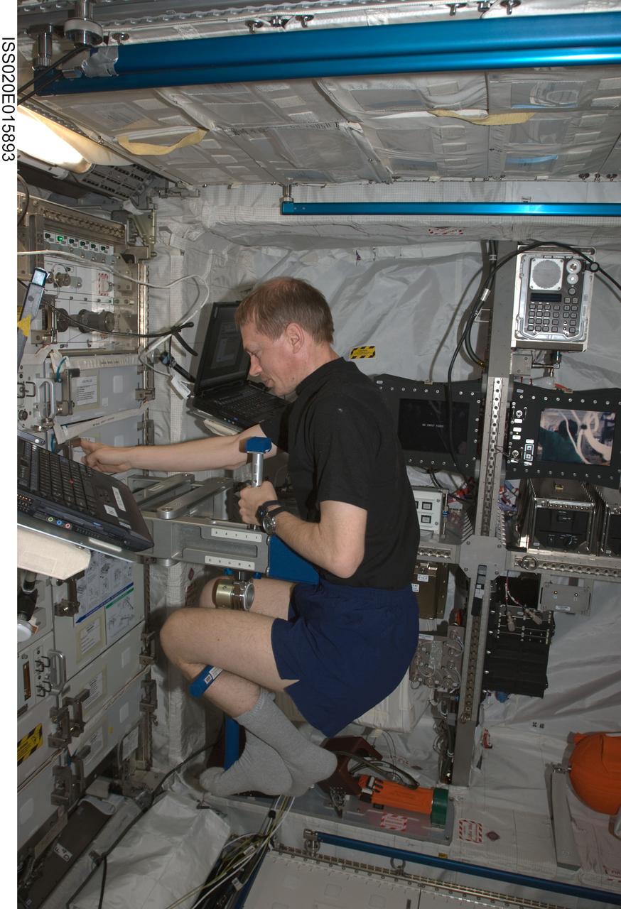
ISS020-E-015893 (29 June 2009) --- European Space Agency astronaut Frank De Winne, Expedition 20 flight engineer, works with the Space Linear Acceleration Mass Measurement Device (SLAMMD) in the Columbus laboratory of the International Space Station.
ISS034-E-026582 (11 Jan. 2013) --- Canadian Space Agency astronaut Chris Hadfield, Expedition 34 flight engineer, uses the Space Linear Acceleration Mass Measurement Device (SLAMMD) in the Columbus laboratory of the International Space Station.
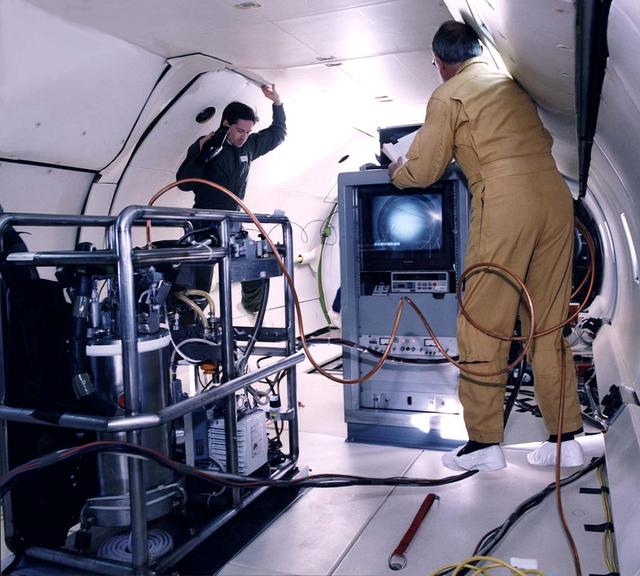
Ted Brunzie and Peter Mason observe the float package and the data rack aboard the DC-9 reduced gravity aircraft. The float package contains a cryostat, a video camera, a pump and accelerometers. The data rack displays and record the video signal from the float package on tape and stores acceleration and temperature measurements on disk.
ISS032-E-024283 (26 Aug. 2012) --- Japan Aerospace Exploration Agency astronaut Aki Hoshide, Expedition 32 flight engineer, uses the Space Linear Acceleration Mass Measurement Device (SLAMMD) in the Columbus laboratory of the International Space Station.
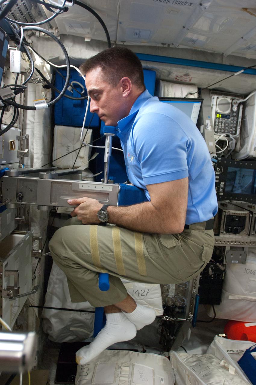
ISS035-E-017874 (8 April 2013) --- NASA astronaut Chris Cassidy, Expedition 35 flight engineer, performs Body Mass Measurement activities using the Space Linear Acceleration Mass Measurement Device (SLAMMD) in the Columbus European Laboratory aboard the Earth-orbiting International Space Station. Since crew members can?t weigh themselves in zero-g, they use this method as the next best thing. Skylab astronauts, the first NASA crew members to fly in space for over a month at a time, some 40 years ago, used a body mass measurement device that was somewhat different from this.
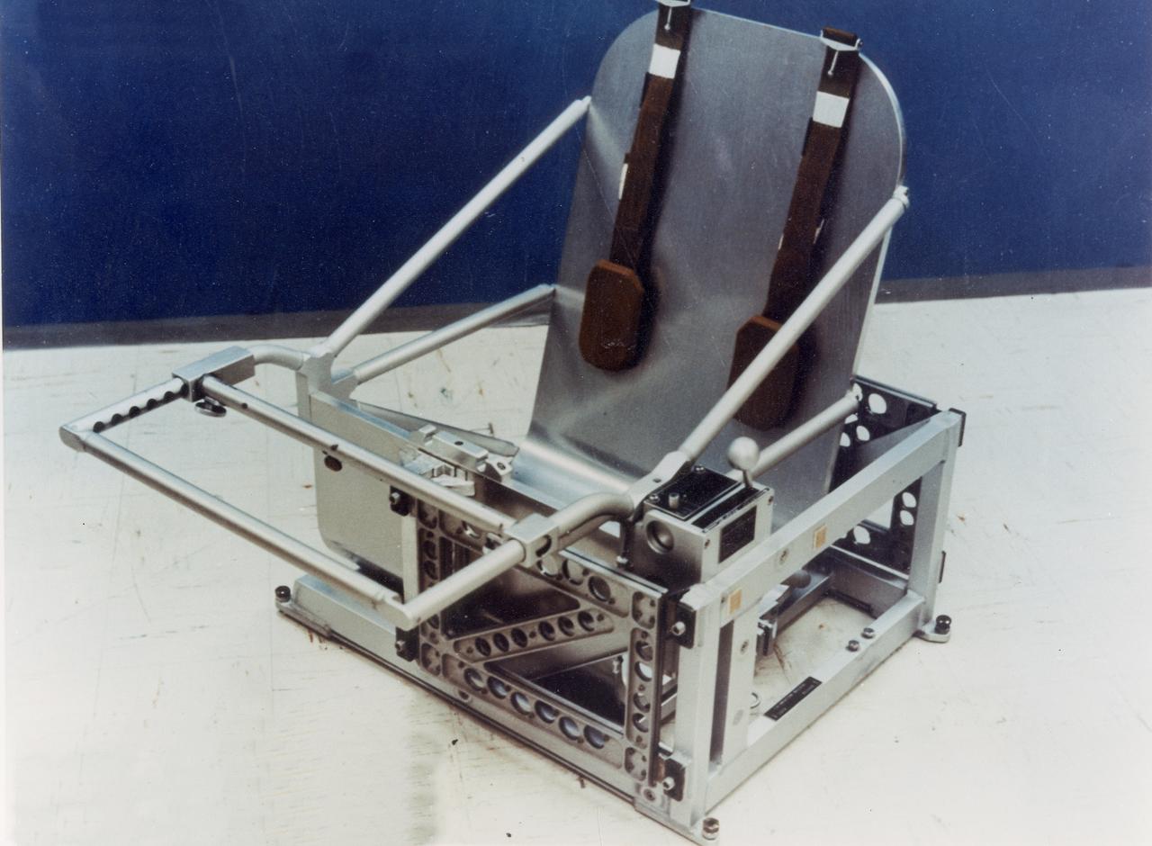
Skylab's Body Mass Measurement chair, the facility of the Body Mass Measurement experiment (M172), is shown here in this 1970 photograph. The M172 experiment determined the body mass of each crew member and observed changes in body masses during flight. Knowledge of exact body mass variations throughout the flight in significantly aided in the correlation of other medical data obtained during the flight. Mass measurements under zero-gravity conditions were achieved by the application of Newton's second law (force equals mass times acceleration). The Marshall Space Flight Center had program management responsibility for the development of Skylab hardware and experiments.
This image, created with data from Juno's Ultraviolet Imaging Spectrometer (UVS), marks the path of Juno's readings of Jupiter's auroras, highlighting the electron measurements that show the discovery of the so-called discrete auroral acceleration processes indicated by the "inverted Vs" in the lower panel (Figure 1). This signature points to powerful magnetic-field-aligned electric potentials that accelerate electrons toward the atmosphere to energies that are far greater than what drive the most intense aurora at Earth. Scientists are looking into why the same processes are not the main factor in Jupiter's most powerful auroras. https://photojournal.jpl.nasa.gov/catalog/PIA21937
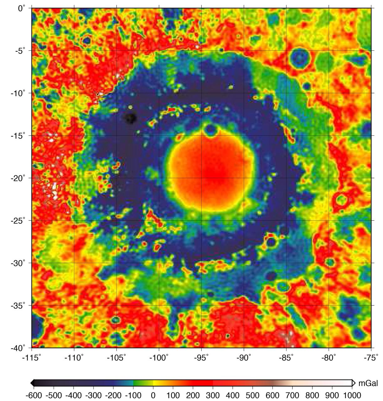
This color-coded map shows the strength of surface gravity around Orientale basin on Earth's moon, derived from data obtained by NASA's GRAIL mission. The GRAIL mission produced a very high-resolution map of gravity over the surface of the entire moon. This plot is zoomed in on the part of that map that features Orientale basin, where the two GRAIL spacecraft flew extremely low near the end of their mission. Their close proximity to the basin made the probes' measurements particularly sensitive to the gravitational acceleration there (due to the inverse squared law). The color scale plots the gravitational acceleration in units of "gals," where 1 gal is one centimeter per second squared, or about 1/1000th of the gravitational acceleration at Earth's surface. (The unit was devised in honor of the astronomer Galileo). Labels on the x and y axes represent latitude and longitude. http://photojournal.jpl.nasa.gov/catalog/PIA21050
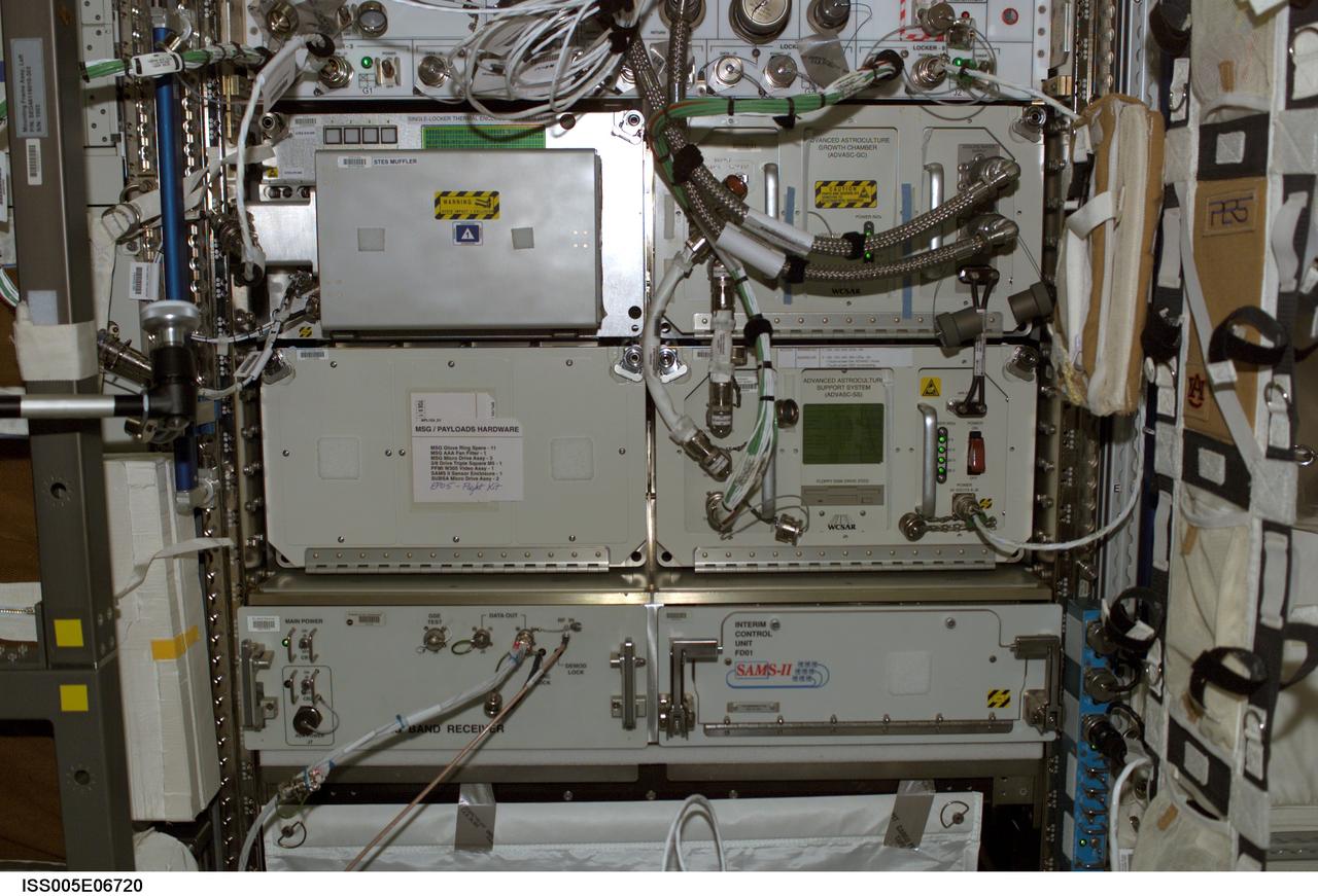
iss005e06720 (7/4/2002) --- Front view of Express Rack 4 in the U.S. Laboratory / Destiny taken during Expedition Five. Visible in the rack are the following items: Single-Locker Thermal Enclosure System (STES) Muffler, Advanced Astroculture Growth Chamber (ADVASC-GC), Advanced Astroculture Support System (ADVASC-SS). And Space Acceleration and Measurement System (SAMS) II.
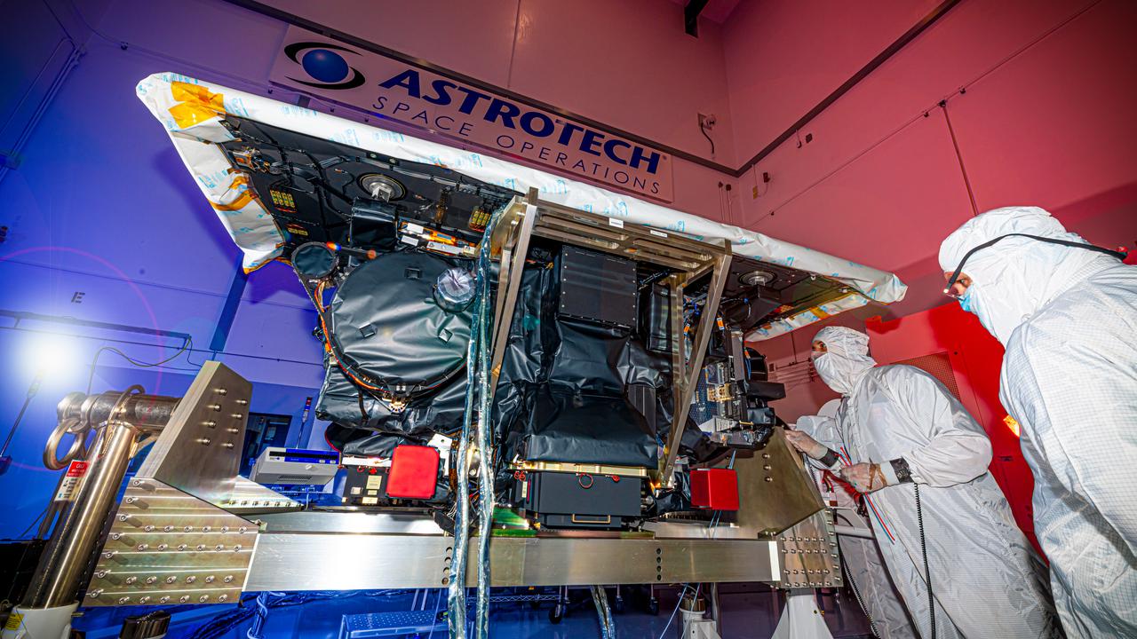
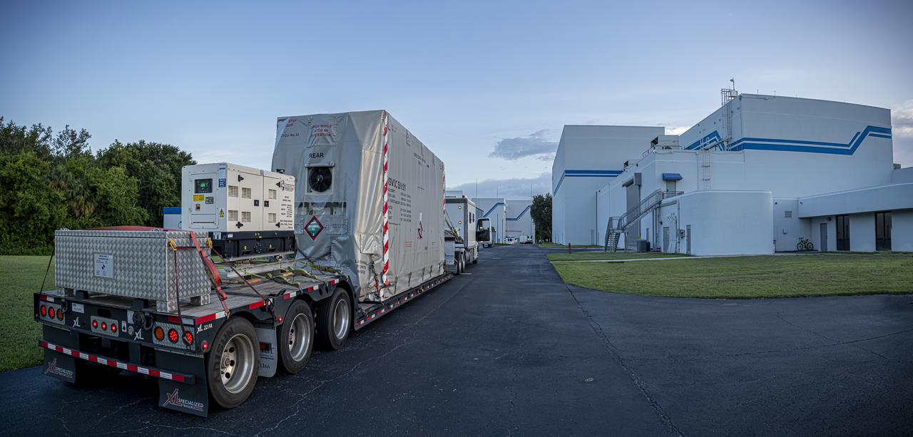
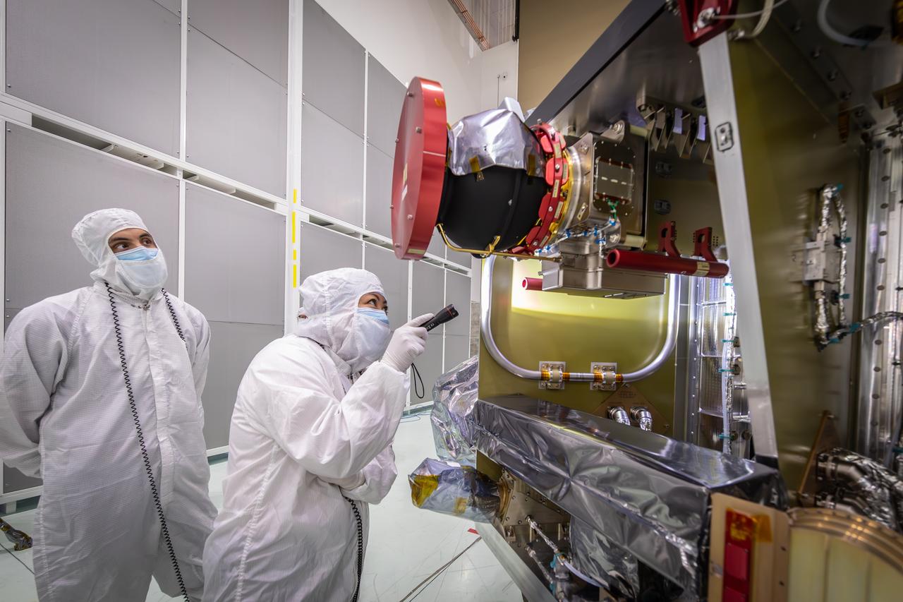
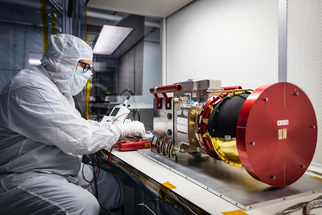
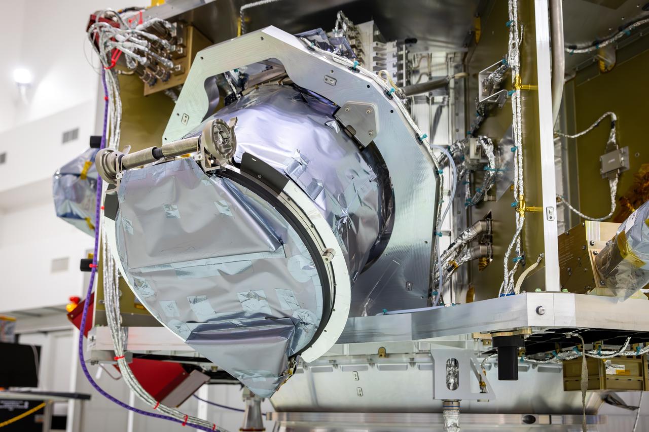
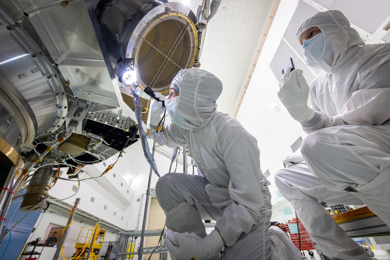
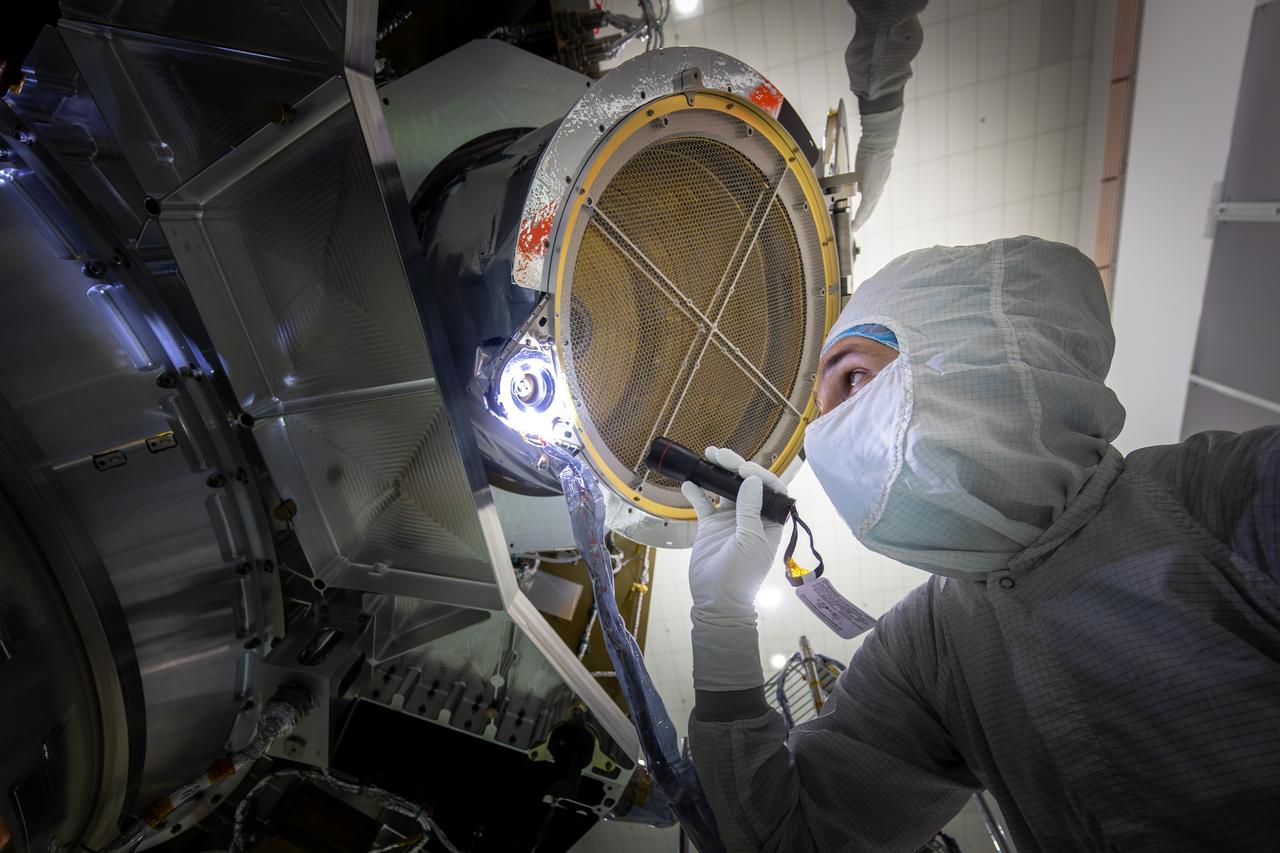
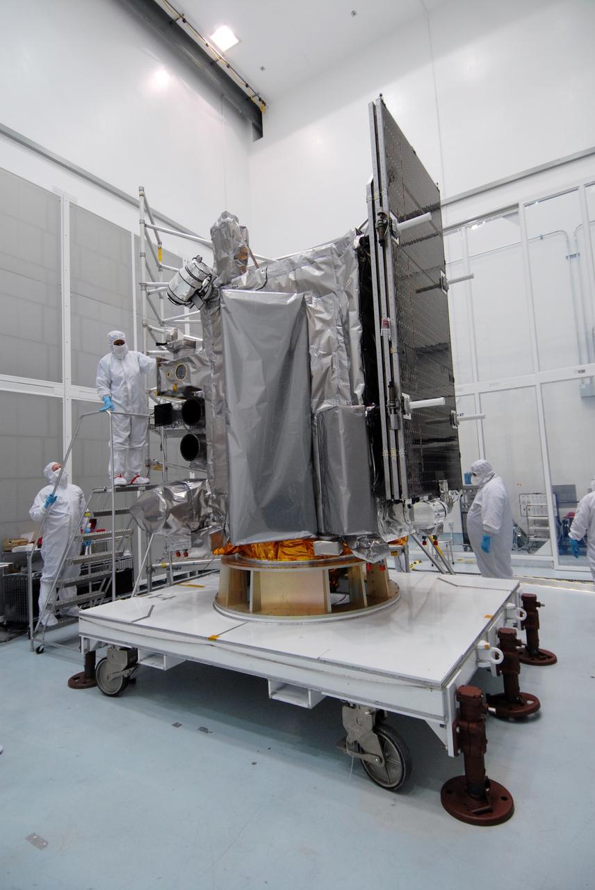
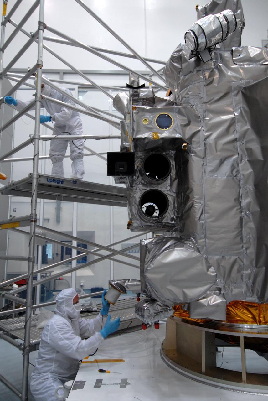
Technicians inspect the National Oceanic and Atmospheric Administration’s (NOAA) Space Weather Follow On–Lagrange 1 (SWFO-L1) Observatory on Thursday, July 24, 2025, following the arrival and unboxing of the observatory at the Astrotech Space Operations Facility near NASA’s Kennedy Space Center in Florida. The SWFO-L1 mission will monitor the Sun and near-Earth environment using a suite of instruments that provide real-time measurements of solar activity. The observatory will launch as a rideshare with NASA’s IMAP (Interstellar Mapping and Acceleration Probe) no earlier than September 2025.
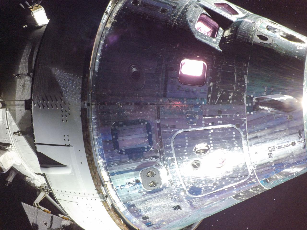
art001e002143 (Dec. 5, 2022) - Solar array-mounted cameras capture close-up images of NASA's Orion Command Module and European Service Module on the 20th day of the Artemis I mission. Windows on the Orion capsule offer a glimpse of “Commander Moonikin Campos," a manikin equipped with sensors measuring radiation, acceleration, and vibration data throughout the mission.
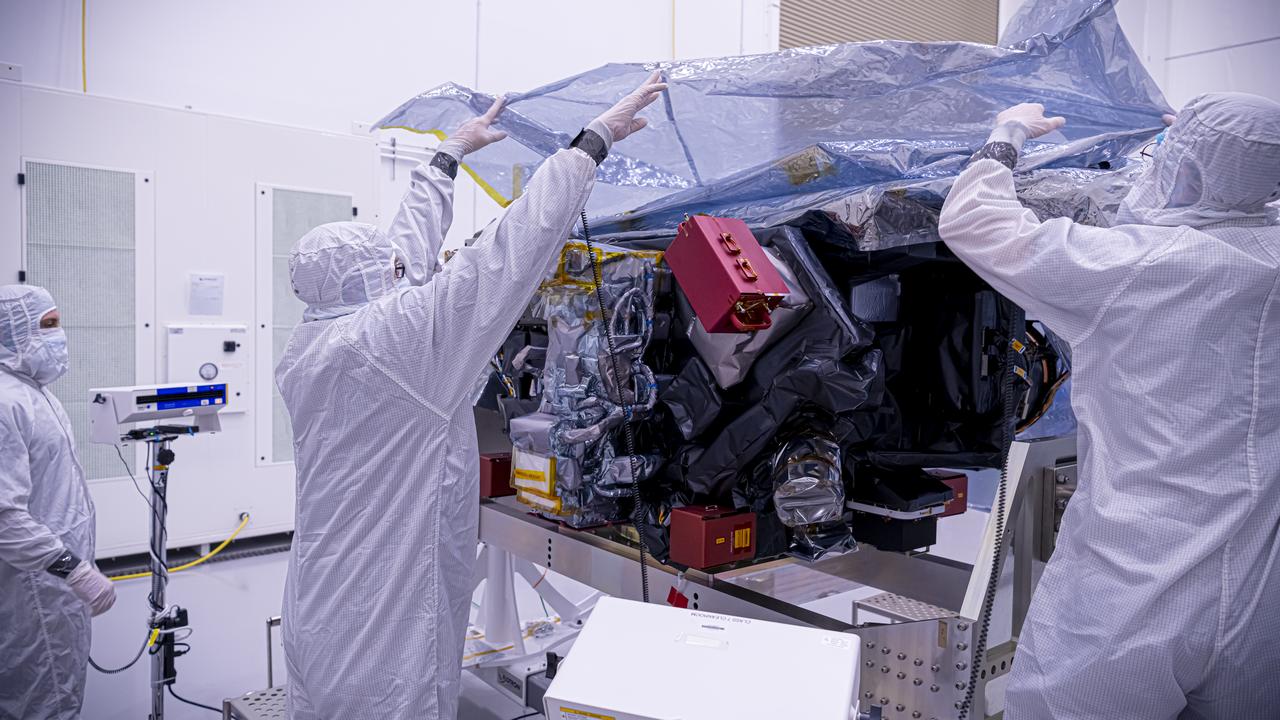
Technicians inspect the National Oceanic and Atmospheric Administration’s (NOAA) Space Weather Follow On–Lagrange 1 (SWFO-L1) Observatory on Thursday, July 24, 2025, following the arrival and unboxing of the observatory at the Astrotech Space Operations Facility near NASA’s Kennedy Space Center in Florida. The SWFO-L1 mission will monitor the Sun and near-Earth environment using a suite of instruments that provide real-time measurements of solar activity. The observatory will launch as a rideshare with NASA’s IMAP (Interstellar Mapping and Acceleration Probe) no earlier than September 2025.
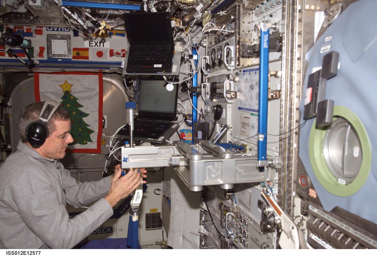
ISS012-E-12577 (16 Dec. 2005) --- Astronaut William S. (Bill) McArthur Jr., Expedition 12 commander and NASA space station science officer, sets up the Space Linear Acceleration Mass Measurement Device (SLAMMD) hardware attached to the Human Research Facility (HRF) rack in the Destiny laboratory of the International Space Station.
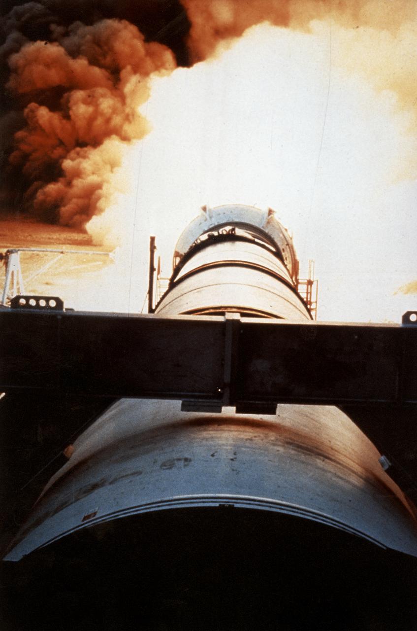
One of the key tests in the effort to return the Space Shuttle to flight following the Challenger accident was testing the development Motor-8 (DM-8). The 126-foot long, 1.2-million-pound motor, designated DM-8, underwent a full-duration horizontal test firing for two minutes at the Thiokol test facility in Utah. It was fitted with more than 500 instruments to measure such things as acceleration, pressure, deflection thrust, strain, temperature, and electrical properties.
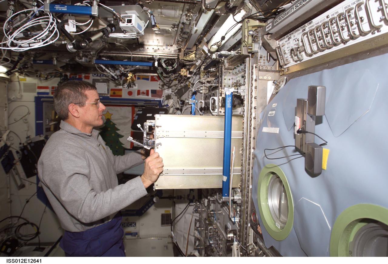
ISS012-E-12641 (16 Dec. 2005) --- Astronaut William S. (Bill) McArthur Jr., Expedition 12 commander and NASA space station science officer, stows the Space Linear Acceleration Mass Measurement Device (SLAMMD) hardware after conducting test operations. SLAMMD hardware was stowed in a stowage drawer on the Human Research Facility (HRF) rack in the Destiny laboratory of the International Space Station.

This artist's concept shows a black hole with an accretion disk -- a flat structure of material orbiting the black hole -- and a jet of hot gas, called plasma. Using NASA's NuSTAR space telescope and a fast camera called ULTRACAM on the William Herschel Observatory in La Palma, Spain, scientists have been able to measure the distance that particles in jets travel before they "turn on" and become bright sources of light. This distance is called the "acceleration zone." https://photojournal.jpl.nasa.gov/catalog/PIA22085
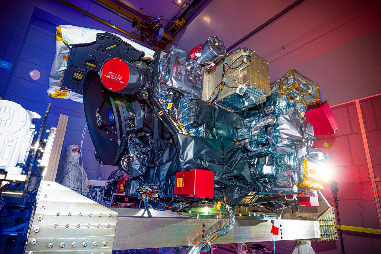
Technicians inspect the National Oceanic and Atmospheric Administration’s (NOAA) Space Weather Follow On–Lagrange 1 (SWFO-L1) Observatory on Thursday, July 24, 2025, following the arrival and unboxing of the observatory at the Astrotech Space Operations Facility near NASA’s Kennedy Space Center in Florida. The SWFO-L1 mission will monitor the Sun and near-Earth environment using a suite of instruments that provide real-time measurements of solar activity. The observatory will launch as a rideshare with NASA’s IMAP (Interstellar Mapping and Acceleration Probe) no earlier than September 2025.

Technicians inspect the National Oceanic and Atmospheric Administration’s (NOAA) Space Weather Follow On–Lagrange 1 (SWFO-L1) Observatory on Thursday, July 24, 2025, following the arrival and unboxing of the observatory at the Astrotech Space Operations Facility near NASA’s Kennedy Space Center in Florida. The SWFO-L1 mission will monitor the Sun and near-Earth environment using a suite of instruments that provide real-time measurements of solar activity. The observatory will launch as a rideshare with NASA’s IMAP (Interstellar Mapping and Acceleration Probe) no earlier than September 2025.
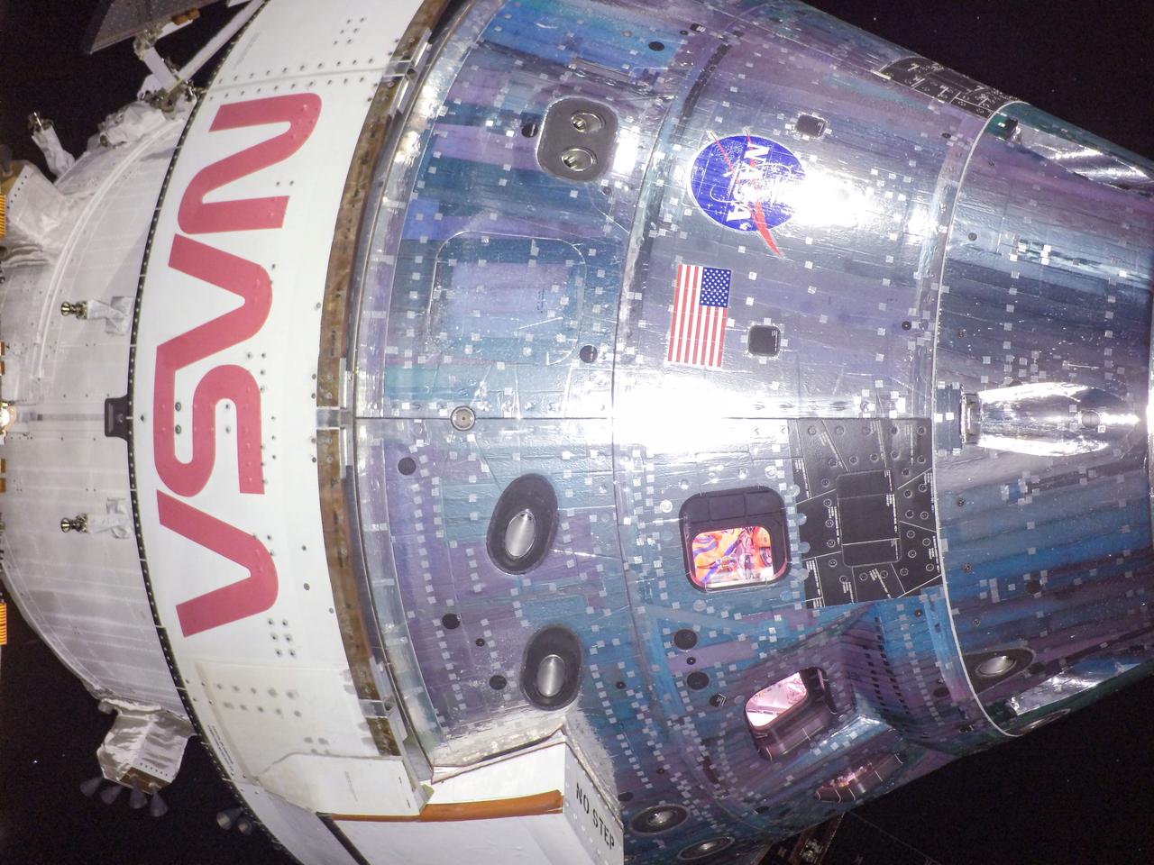
art001e002135 (Dec. 5, 2022) - Solar array-mounted cameras capture close-up images of NASA's Orion Command Module and European Service Module on the 20th day of the Artemis I mission. Windows on the Orion capsule offer a glimpse of “Commander Moonikin Campos," a manikin equipped with sensors measuring radiation, acceleration, and vibration data throughout the mission.
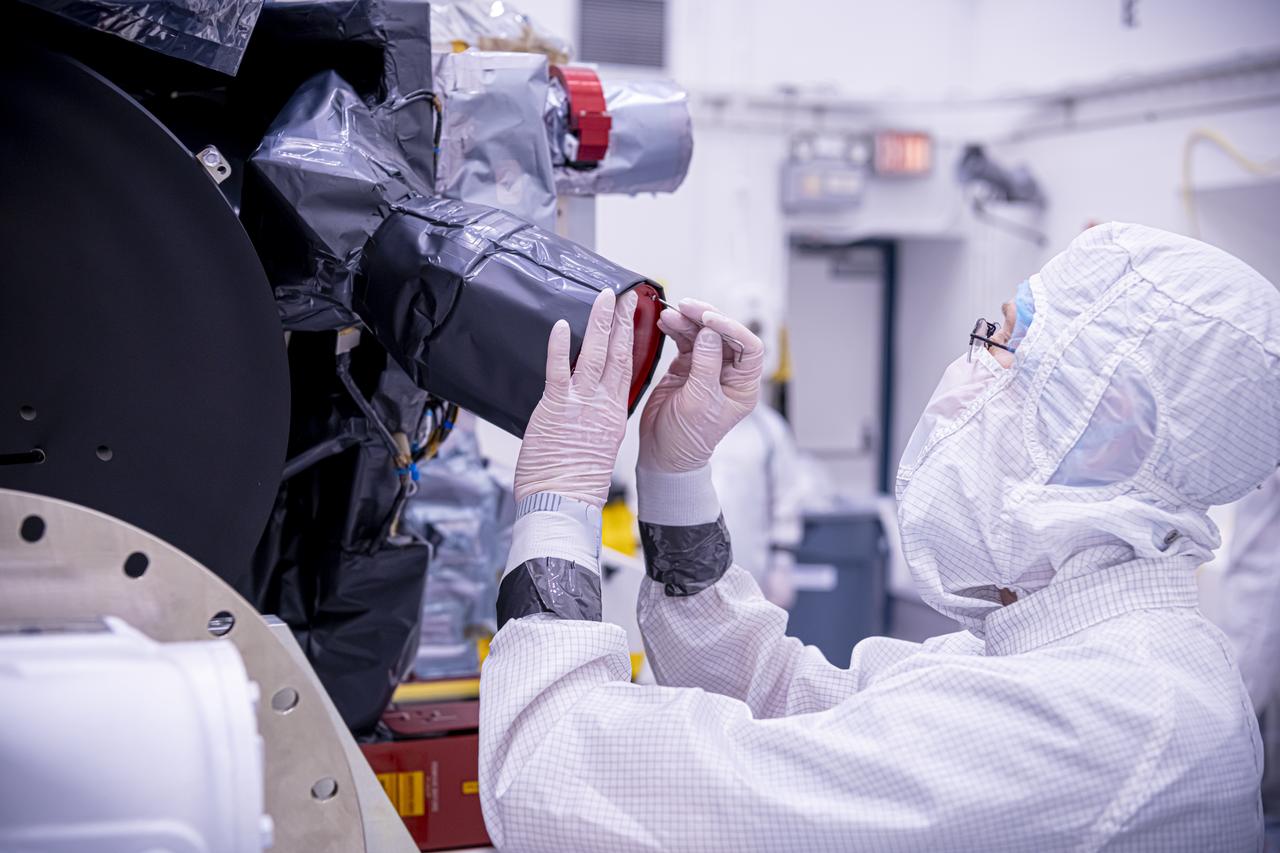
Technicians inspect the National Oceanic and Atmospheric Administration’s (NOAA) Space Weather Follow On–Lagrange 1 (SWFO-L1) Observatory on Thursday, July 24, 2025, following the arrival and unboxing of the observatory at the Astrotech Space Operations Facility near NASA’s Kennedy Space Center in Florida. The SWFO-L1 mission will monitor the Sun and near-Earth environment using a suite of instruments that provide real-time measurements of solar activity. The observatory will launch as a rideshare with NASA’s IMAP (Interstellar Mapping and Acceleration Probe) no earlier than September 2025.
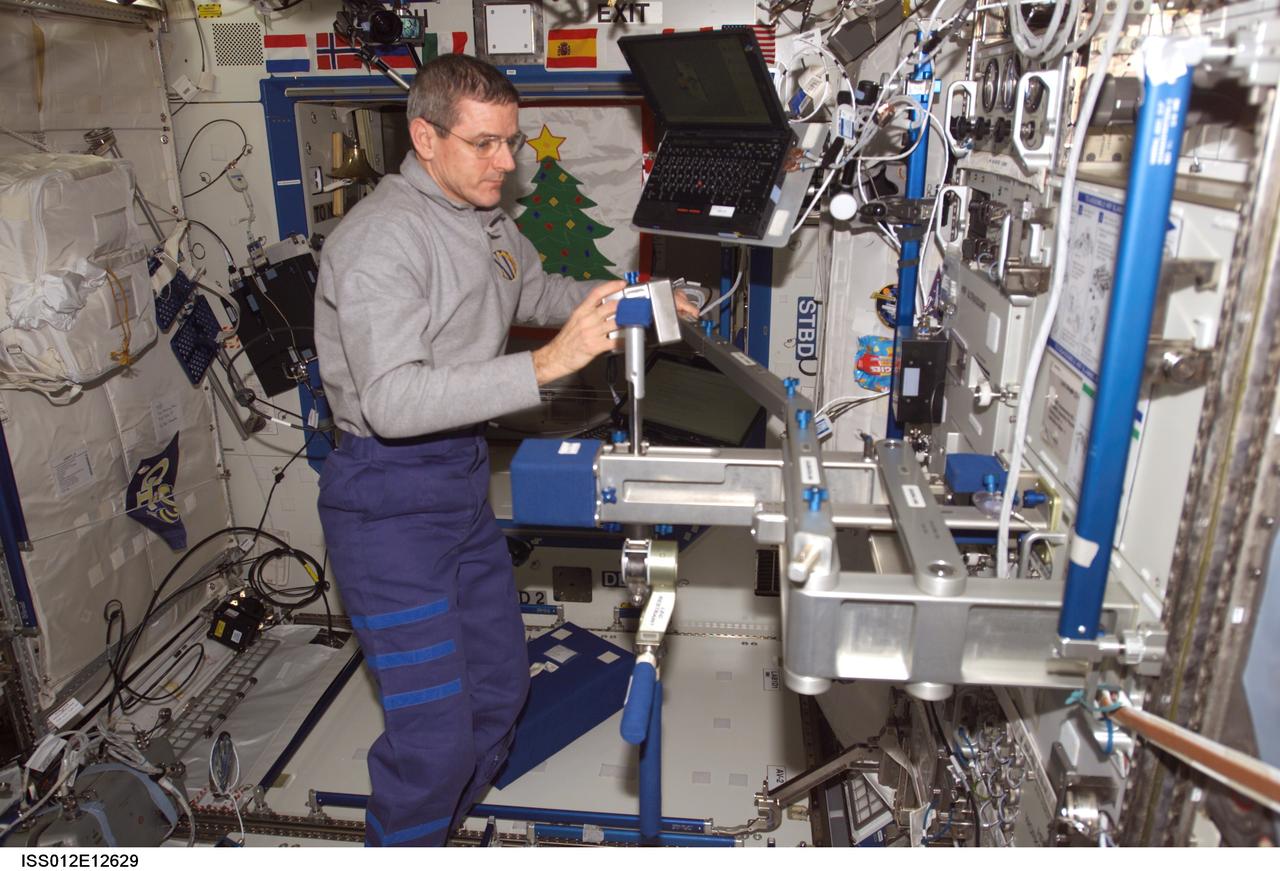
ISS012-E-12629 (16 Dec. 2005) --- Astronaut William S. (Bill) McArthur Jr., Expedition 12 commander and NASA space station science officer, sets up the calibration arm on the Space Linear Acceleration Mass Measurement Device (SLAMMD) attached to the Human Research Facility (HRF) rack in the Destiny laboratory of the International Space Station.
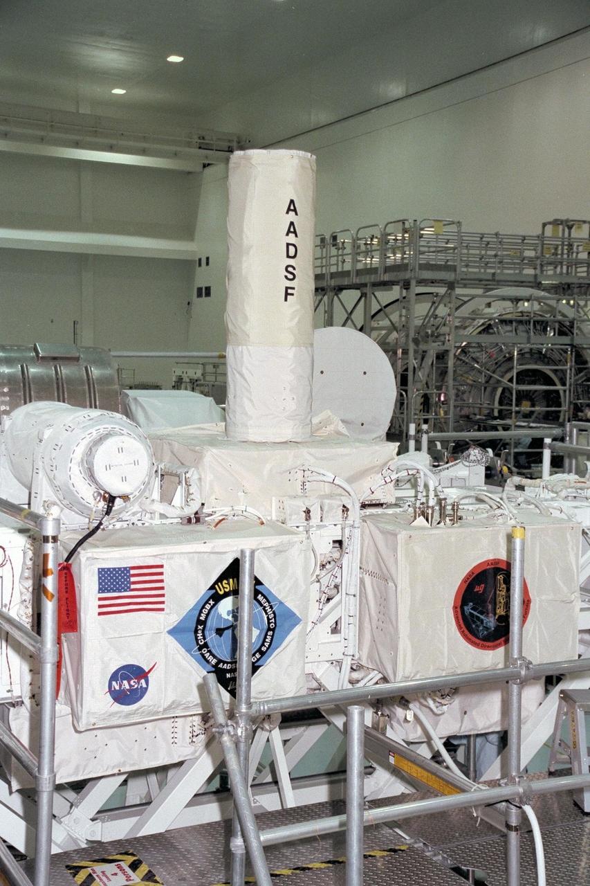
United States Microgravity Payload-4 (USMP-4) experiments are prepared to be flown on Space Shuttle mission STS-87 in the Space Station Processing Facility at Kennedy Space Center (KSC). The large white vertical cylinder in the center of the photo is the Advanced Automated Directional Solidification Furnace (AADSF) and the horizontal tube to the left of it is MEPHISTO, a French acronym for a cooperative American-French investigation of the fundamentals of crystal growth. Seen at right behind the AADSF in the circular white cover is the Isothermal Dendritic Growth Experiment (IDGE), which will be used to study the dendritic solidification of molten materials in the microgravity environment. Under the multi-layer insulation with the American flag and mission logo is the Space Acceleration Measurement System, or SAMS, which measures the microgravity conditions in which the experiments are conducted. All of these experiments are scheduled for launch aboard STS-87 on Nov. 19 from KSC
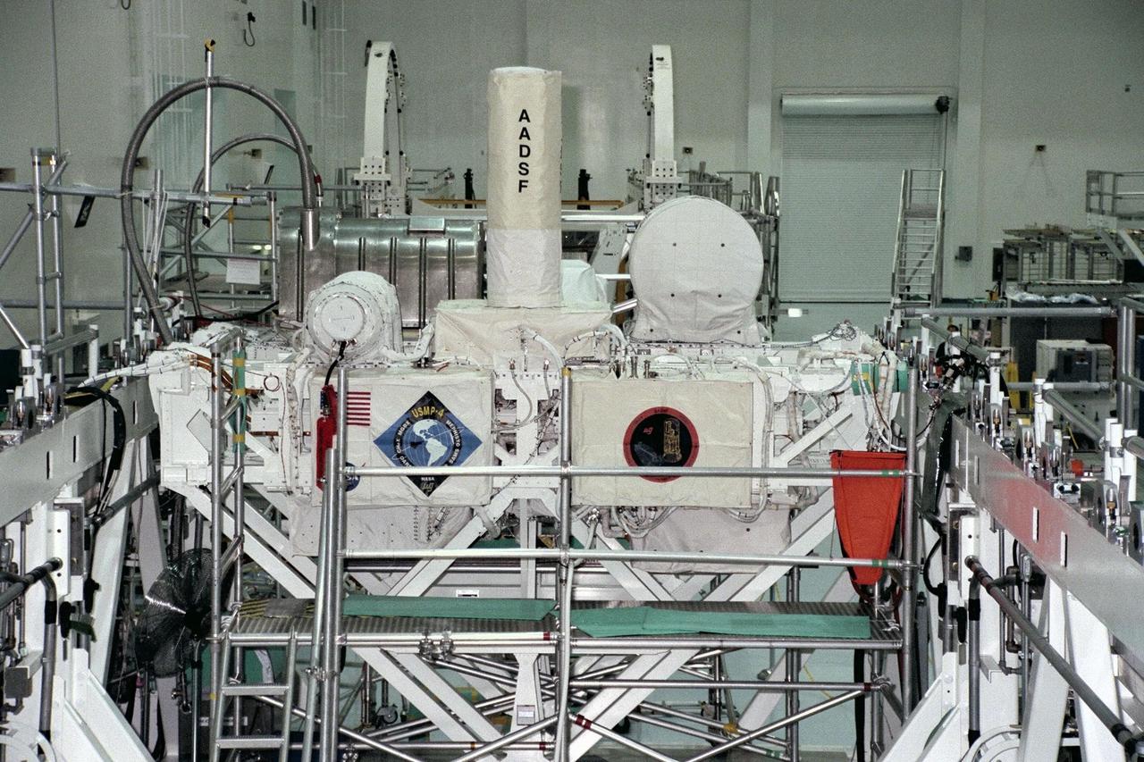
United States Microgravity Payload-4 (USMP-4) experiments are prepared to be flown on Space Shuttle mission STS-87 in the Space Station Processing Facility at Kennedy Space Center (KSC). Seen in the foreground at right is the USMP-4 logo with the acronyms of its experiments. Above the American flag at left is the MEPHISTO experiment, a cooperative American and French investigation of the fundamentals of crystal growth. Scientists will study changes in solidification rates, temperature, and interface shape of an alloy to understand how these changes affect composition and properties of the metal produced. Under the multi-layer insulation with the American flag and mission logo is the Space Acceleration Measurement System, or SAMS, which measures the microgravity conditions in which the experiments are conducted. All USMP-4 experiments are scheduled for launch aboard STS-87 on Nov. 19 from KSC
United States Microgravity Payload-4 (USMP-4) experiments are prepared to be flown on Space Shuttle mission STS-87 in the Space Station Processing Facility at Kennedy Space Center (KSC). The large white vertical cylinder in the middle of the photo is the Advanced Automated Directional Solidification Furnace (AADSF) and the horizontal tube to its left is MEPHISTO, the French acronym for a cooperative American-French investigation of the fundamentals of crystal growth. Seen to the right of the AADSF is the Isothermal Dendritic Growth Experiment (IDGE), which will be used to study the dendritic solidification of molten materials in the microgravity environment. Under the multi-layer insulation with the American flag and mission logo is the Space Acceleration Measurement System, or SAMS, which measures the microgravity conditions in which the experiments are conducted. All of these experiments are scheduled for launch aboard STS-87 on Nov. 19 from KSC
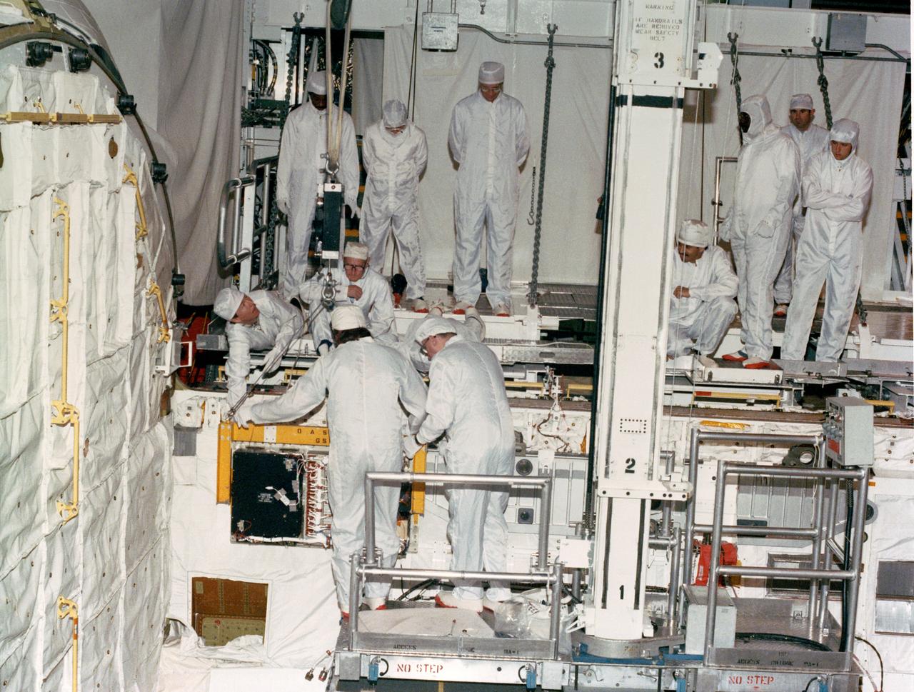
S88-37764 (18 April 1988) --- OASIS, instrumentation which will record the environment experienced by Discovery during the STS-26 Space Shuttle mission, is lowered into position for attachment to the orbiter's aft port sill. Instrumentation sensors in the payload bay which are connected to the tape recorder module will document a variety of environmental measurements during various phases of the flight including temperature, pressure, vibration, sounds, acceleration, stress, and strain. OASIS will also record data during the Flight Readiness Firing. NASA is flying OASIS aboard Discovery in support of the Inertial Upper Stage (IUS) program office of the Air Force Space Division. The system was developed by Lockheed under a NASA contract, funded by the Air Force.
Onboard Space Shuttle Discovery (STS-42) Astronaut Norman E. Thagard, payload commander, and Canadian payload specialist Roberta L. Bondar are busily engaged with experiments in the International Microgravity Laboratory (IML-1) science module. Bondar reads a checklist near the Biorack while Thagard performs a VCR tape change-out. The two, along with four other NASA astronauts and a second IML-1 payload specialist spent more than eight days conducting experiments in Earth orbit. Part of the Space Acceleration Measurement System is in center foreground.
Technicians reintegrate the Compact Dual Ion Composition Experiment (CoDICE) instrument of NASA’s IMAP (Interstellar Mapping and Acceleration Probe) observatory inside the high bay at the Astrotech Space Operations Facility near the agency’s Kennedy Space Center in Florida on Friday, June 20, 2025. CoDICE will measure solar wind particles flowing from the Sun and pickup ions that entered the heliosphere from outside the solar system, as well as the direction of travel, and types of specific species of pickup ions. Launch of the IMAP mission is targeted for no earlier than September 2025 aboard a SpaceX Falcon 9 rocket from Launch Complex 39A at NASA Kennedy.

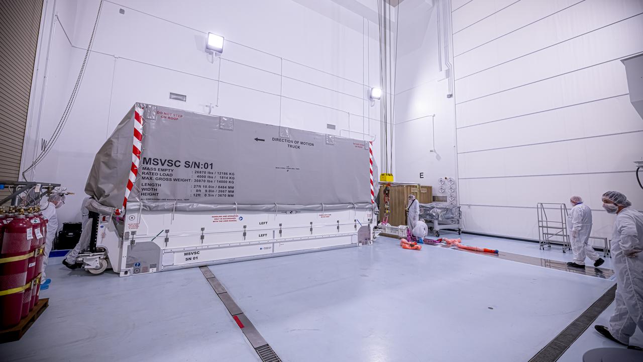
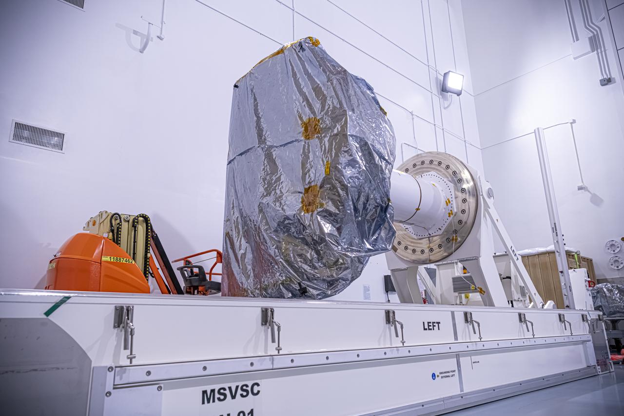
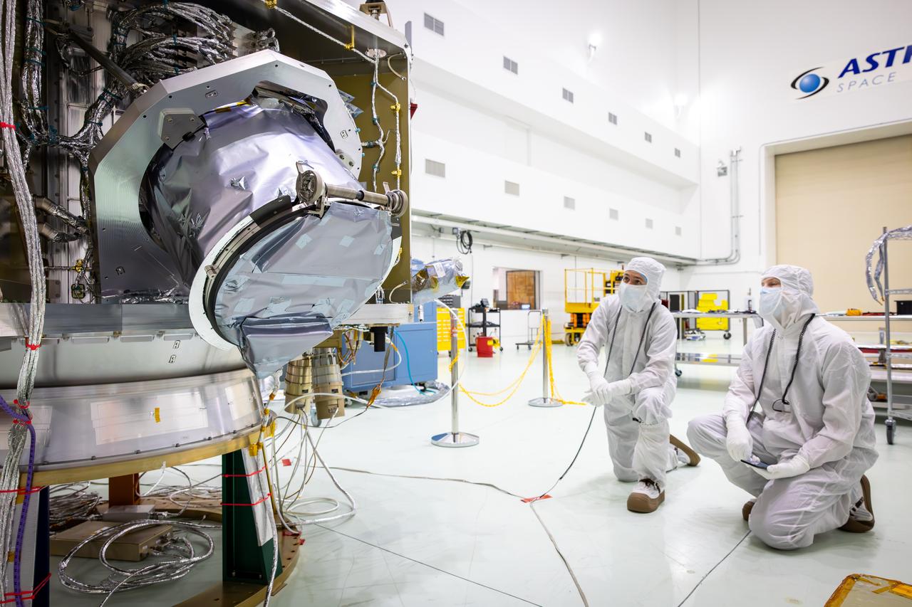
Technicians rotate the National Oceanic and Atmospheric Administration’s (NOAA) Space Weather Follow On–Lagrange 1 (SWFO-L1) Observatory vertically and use a crane to lift it from its transport container on Wednesday, July 23, 2025, following the arrival and unboxing of the observatory at the Astrotech Space Operations Facility near NASA’s Kennedy Space Center in Florida. The SWFO-L1 mission will monitor the Sun and near-Earth environment using a suite of instruments that provide real-time measurements of solar activity. The observatory will launch as a rideshare with NASA’s IMAP (Interstellar Mapping and Acceleration Probe) no earlier than September 2025.
The National Oceanic and Atmospheric Administration’s (NOAA) Space Weather Follow On–Lagrange 1 (SWFO-L1) Observatory, set to provide quicker and more accurate space weather forecasts, arrived Sunday, July 20, 2025, at the Astrotech Space Operations Facility near NASA’s Kennedy Space Center in Florida. The SWFO-L1 mission will monitor the Sun and near-Earth environment using a suite of instruments that provide real-time measurements of solar activity. The observatory will launch as a rideshare with NASA’s IMAP (Interstellar Mapping and Acceleration Probe) no earlier than September 2025.
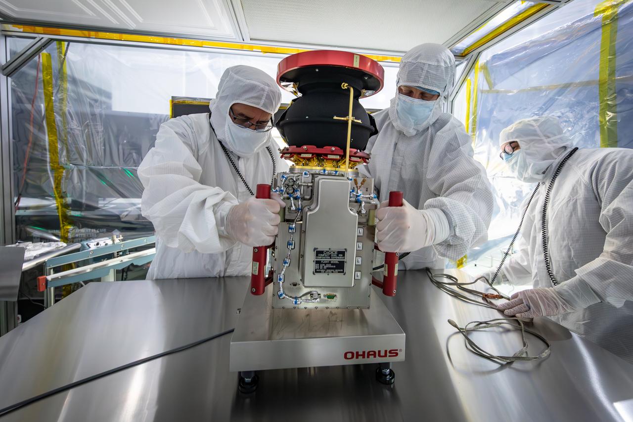
Technicians reintegrate the Compact Dual Ion Composition Experiment (CoDICE) instrument of NASA’s IMAP (Interstellar Mapping and Acceleration Probe) observatory inside the high bay at the Astrotech Space Operations Facility near the agency’s Kennedy Space Center in Florida on Friday, June 20, 2025. CoDICE will measure solar wind particles flowing from the Sun and pickup ions that entered the heliosphere from outside the solar system, as well as the direction of travel, and types of specific species of pickup ions. Launch of the IMAP mission is targeted for no earlier than September 2025 aboard a SpaceX Falcon 9 rocket from Launch Complex 39A at NASA Kennedy.
The National Oceanic and Atmospheric Administration’s (NOAA) Space Weather Follow On–Lagrange 1 (SWFO-L1) Observatory, set to provide quicker and more accurate space weather forecasts, arrived Sunday, July 20, 2025, at the Astrotech Space Operations Facility near NASA’s Kennedy Space Center in Florida. The SWFO-L1 mission will monitor the Sun and near-Earth environment using a suite of instruments that provide real-time measurements of solar activity. The observatory will launch as a rideshare with NASA’s IMAP (Interstellar Mapping and Acceleration Probe) no earlier than September 2025.
A photographer captures the National Oceanic and Atmospheric Administration’s (NOAA) Space Weather Follow On–Lagrange 1 (SWFO-L1) Observatory laying horizontal on Tuesday, July 22, 2025, following the arrival and unboxing of the observatory at the Astrotech Space Operations Facility near NASA’s Kennedy Space Center in Florida. The SWFO-L1 mission will monitor the Sun and near-Earth environment using a suite of instruments that provide real-time measurements of solar activity. The observatory will launch as a rideshare with NASA’s IMAP (Interstellar Mapping and Acceleration Probe) no earlier than September 2025.
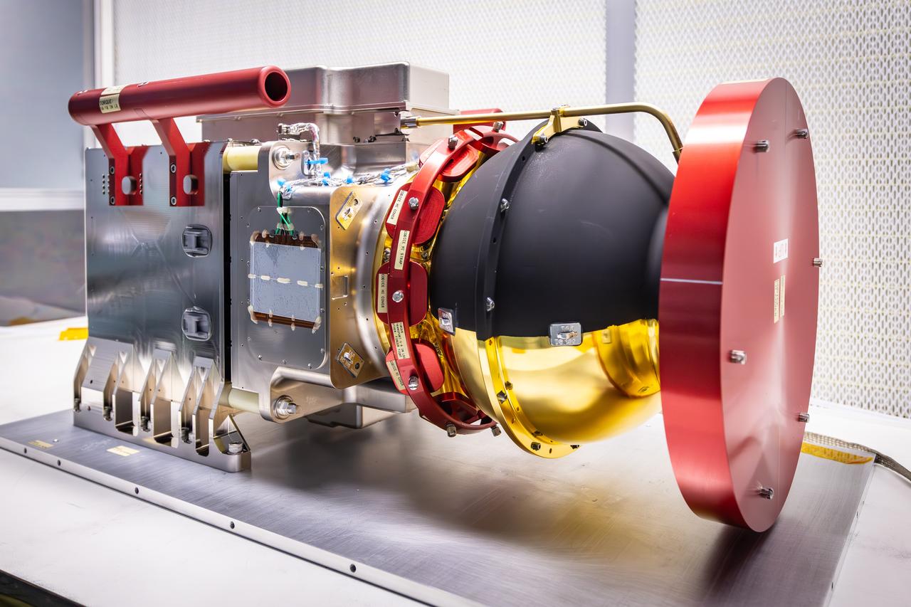
Technicians perform tests on the Compact Dual Ion Composition Experiment (CoDICE) instrument of NASA’s IMAP (Interstellar Mapping and Acceleration Probe) observatory inside the high bay at the Astrotech Space Operations Facility near the agency’s Kennedy Space Center in Florida on Tuesday, June 17, 2025. CoDICE will measure solar wind particles flowing from the Sun and pickup ions that entered the heliosphere from outside the solar system, as well as the direction of travel, and types of specific species of pickup ions. Launch of the IMAP mission is targeted for no earlier than September 2025 aboard a SpaceX Falcon 9 rocket from Launch Complex 39A at NASA Kennedy.
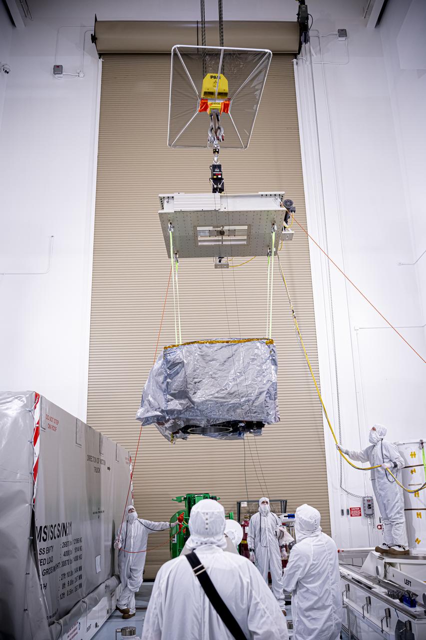
Technicians rotate the National Oceanic and Atmospheric Administration’s (NOAA) Space Weather Follow On–Lagrange 1 (SWFO-L1) Observatory vertically and use a crane to lift it from its transport container on Wednesday, July 23, 2025, following the arrival and unboxing of the observatory at the Astrotech Space Operations Facility near NASA’s Kennedy Space Center in Florida. The SWFO-L1 mission will monitor the Sun and near-Earth environment using a suite of instruments that provide real-time measurements of solar activity. The observatory will launch as a rideshare with NASA’s IMAP (Interstellar Mapping and Acceleration Probe) no earlier than September 2025.
Technicians reintegrate the Compact Dual Ion Composition Experiment (CoDICE) instrument of NASA’s IMAP (Interstellar Mapping and Acceleration Probe) observatory inside the high bay at the Astrotech Space Operations Facility near the agency’s Kennedy Space Center in Florida on Friday, June 20, 2025. CoDICE will measure solar wind particles flowing from the Sun and pickup ions that entered the heliosphere from outside the solar system, as well as the direction of travel, and types of specific species of pickup ions. Launch of the IMAP mission is targeted for no earlier than September 2025 aboard a SpaceX Falcon 9 rocket from Launch Complex 39A at NASA Kennedy.
Technicians rotate the National Oceanic and Atmospheric Administration’s (NOAA) Space Weather Follow On–Lagrange 1 (SWFO-L1) Observatory vertically and use a crane to lift it from its transport container on Wednesday, July 23, 2025, following the arrival and unboxing of the observatory at the Astrotech Space Operations Facility near NASA’s Kennedy Space Center in Florida. The SWFO-L1 mission will monitor the Sun and near-Earth environment using a suite of instruments that provide real-time measurements of solar activity. The observatory will launch as a rideshare with NASA’s IMAP (Interstellar Mapping and Acceleration Probe) no earlier than September 2025.
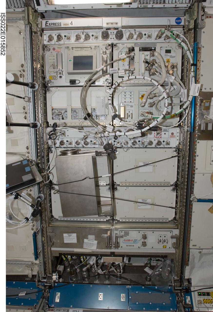
iss022e015852 (12/30/2009) --- The image shows a front view of EXpedite the PRocessing of Experiments to Space Station EXPRESS Rack 4 (Rack 4,JPM/1F5) in the Japanese Experiment Module (JEM) Japanese Pressurized Module (JPM). Equipment visible in the EXPRESS Rack includes the Biotechnology Specimen Temperature Controller (BSTC) and the Gas Supply Module (GSM) support hardware for the CBOSS (Cellular Biotechnology Operations Support Systems) investigations, and the Device for the Study of Critical Liquids and Crystallization (DECLIC). Also visible is the Space Acceleration Measurement System (SAMS) II.
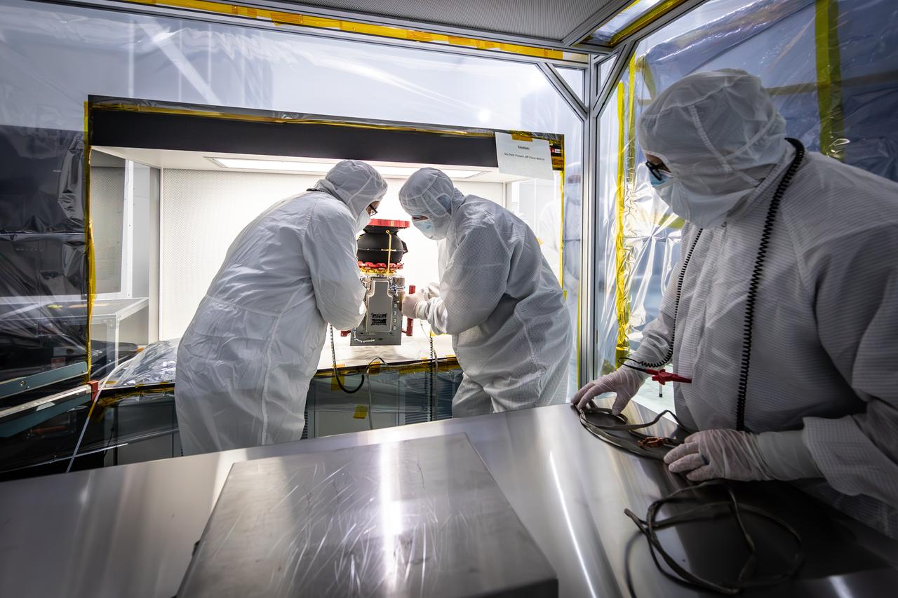
Technicians reintegrate the Compact Dual Ion Composition Experiment (CoDICE) instrument of NASA’s IMAP (Interstellar Mapping and Acceleration Probe) observatory inside the high bay at the Astrotech Space Operations Facility near the agency’s Kennedy Space Center in Florida on Friday, June 20, 2025. CoDICE will measure solar wind particles flowing from the Sun and pickup ions that entered the heliosphere from outside the solar system, as well as the direction of travel, and types of specific species of pickup ions. Launch of the IMAP mission is targeted for no earlier than September 2025 aboard a SpaceX Falcon 9 rocket from Launch Complex 39A at NASA Kennedy.
A technician performs tests on the Compact Dual Ion Composition Experiment (CoDICE) instrument of NASA’s IMAP (Interstellar Mapping and Acceleration Probe) observatory inside the high bay at the Astrotech Space Operations Facility near the agency’s Kennedy Space Center in Florida on Tuesday, June 17, 2025. CoDICE will measure solar wind particles flowing from the Sun and pickup ions that entered the heliosphere from outside the solar system, as well as the direction of travel, and types of specific species of pickup ions. Launch of the IMAP mission is targeted for no earlier than September 2025 aboard a SpaceX Falcon 9 rocket from Launch Complex 39A at NASA Kennedy.

The National Aeronautics and Space Administration (NASA) Lewis Research Center tested 16 commercially-manufactured electric vehicles, including this Metro, during the mid-1970s. Lewis and the Energy Research and Development Administration (ERDA) engaged in several energy-related programs in the mid-1970s, including the Electric Vehicle Project. NASA and ERDA undertook the program in 1976 to determine the state of the current electric vehicle technology. As part of the project, Lewis and ERDA tested every commercially available electric car model. Electric Vehicle Associates, located in a Cleveland suburb, modified a Renault 12 vehicle to create this Metro. Its 1040-pound golfcart-type battery provided approximately 106 minutes of operation. The tests analyzed the vehicle’s range, acceleration, coast-down, braking, and energy consumption. Some of the vehicles had analog data recording systems to measure the battery during operation and sensors to determine speed and distance. The researchers found the performance of the different vehicles varied significantly. In general, the range, acceleration, and speed were lower than that found on conventional vehicles. They also found that traditional gasoline-powered vehicles were as efficient as the electric vehicles. The researchers concluded, however, that advances in battery technology and electric drive systems would significantly improve efficiency and performance.
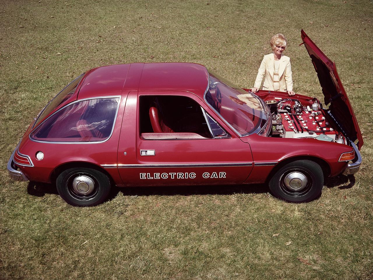
The National Aeronautics and Space Administration (NASA) Lewis Research Center tested 16 commercially-manufactured electric vehicles, including this modified Pacer, during the mid-1970s. The Electric Vehicle Project was just one of several energy-related programs that Lewis and the Energy Research and Development Administration (ERDA) undertook in the mid-1970s. NASA and ERDA embarked on this program in 1976 to determine the state of the current electric vehicle technology. As part of the project, Lewis tested a fleet composed of every commercially available electric car. The Cleveland-area Electric Vehicle Associates modified an American Motors Pacer vehicle to create this Change-of-Pace Coupe. It was powered by twenty 6-volt batteries whose voltage could be varied by a foot control. The tests analyzed the vehicle’s range, acceleration, coast-down, braking, and energy consumption. Some of the vehicles had analog data recording systems to measure the battery during operation and sensors to determine speed and distance. Lewis researchers found that the vehicle performance varied significantly from model to model. In general, the range, acceleration, and speed were lower than conventional vehicles. They also found that traditional gasoline-powered vehicles were as efficient as the electric vehicles. The researchers concluded, however, that advances in battery technology and electric drive systems would significantly improve the performance and efficiency.
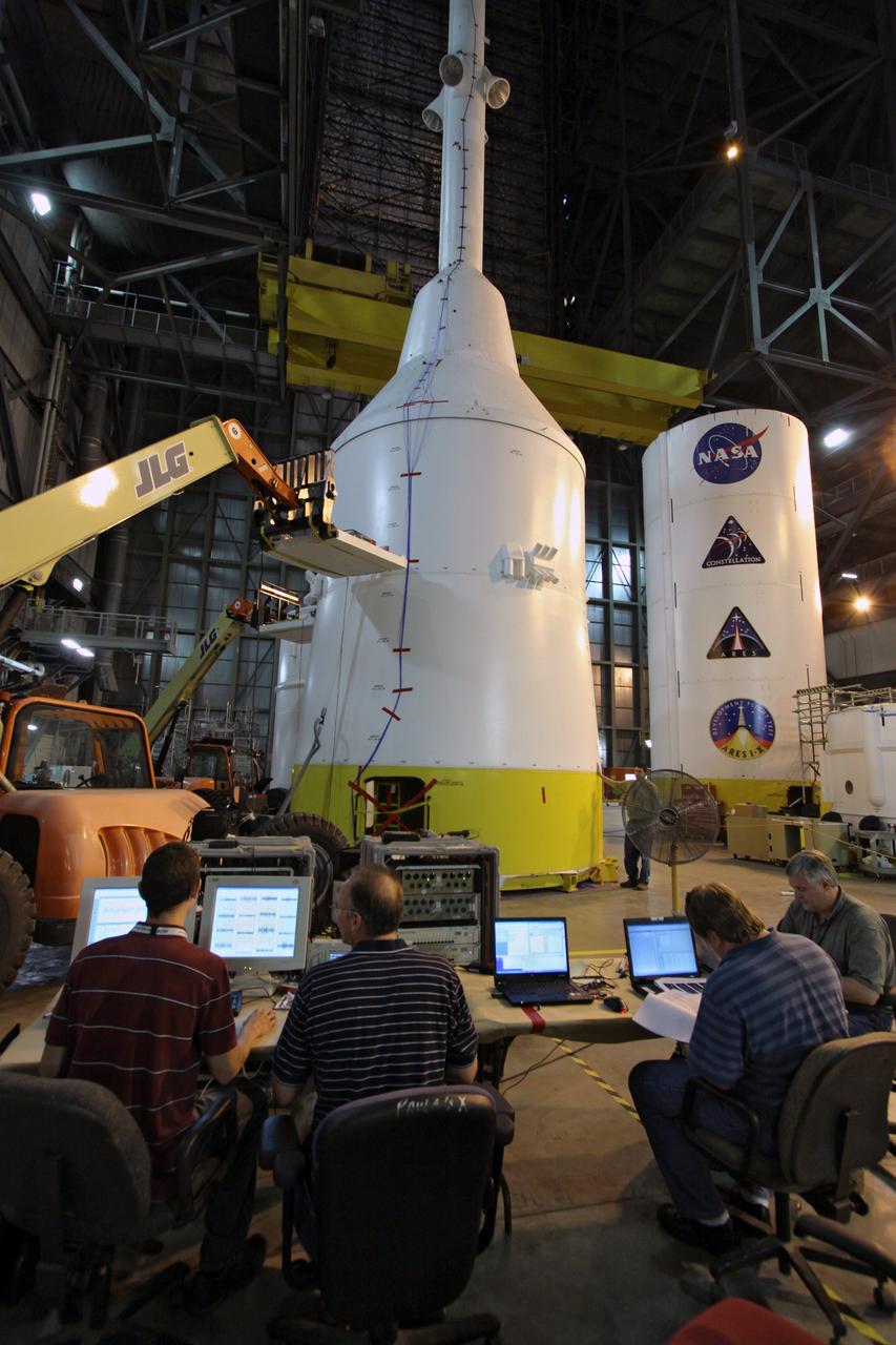
CAPE CANAVERAL, Fla. – In high bay 4 of the Vehicle Assembly Building at NASA's Kennedy Space Center in Florida, technicians begin the modal survey testing on the top part of the Ares I-X (center) after sensors were placed on the stack. The top consists of the launch abort tower, crew module, service module and spacecraft adaptor. Shakers will impose random loads/vibrations to determine the flight test vehicle’s first several bending modes and the strategically located sensors throughout the stacks will measure the amount, acceleration and direction of movement. The purpose of the testing is to confirm that Ares I-X will behave as predicted as it lifts off the pad and powers through the initial stage of flight in a demonstration flight later this year. Photo credit: NASA/Jack Pfaller
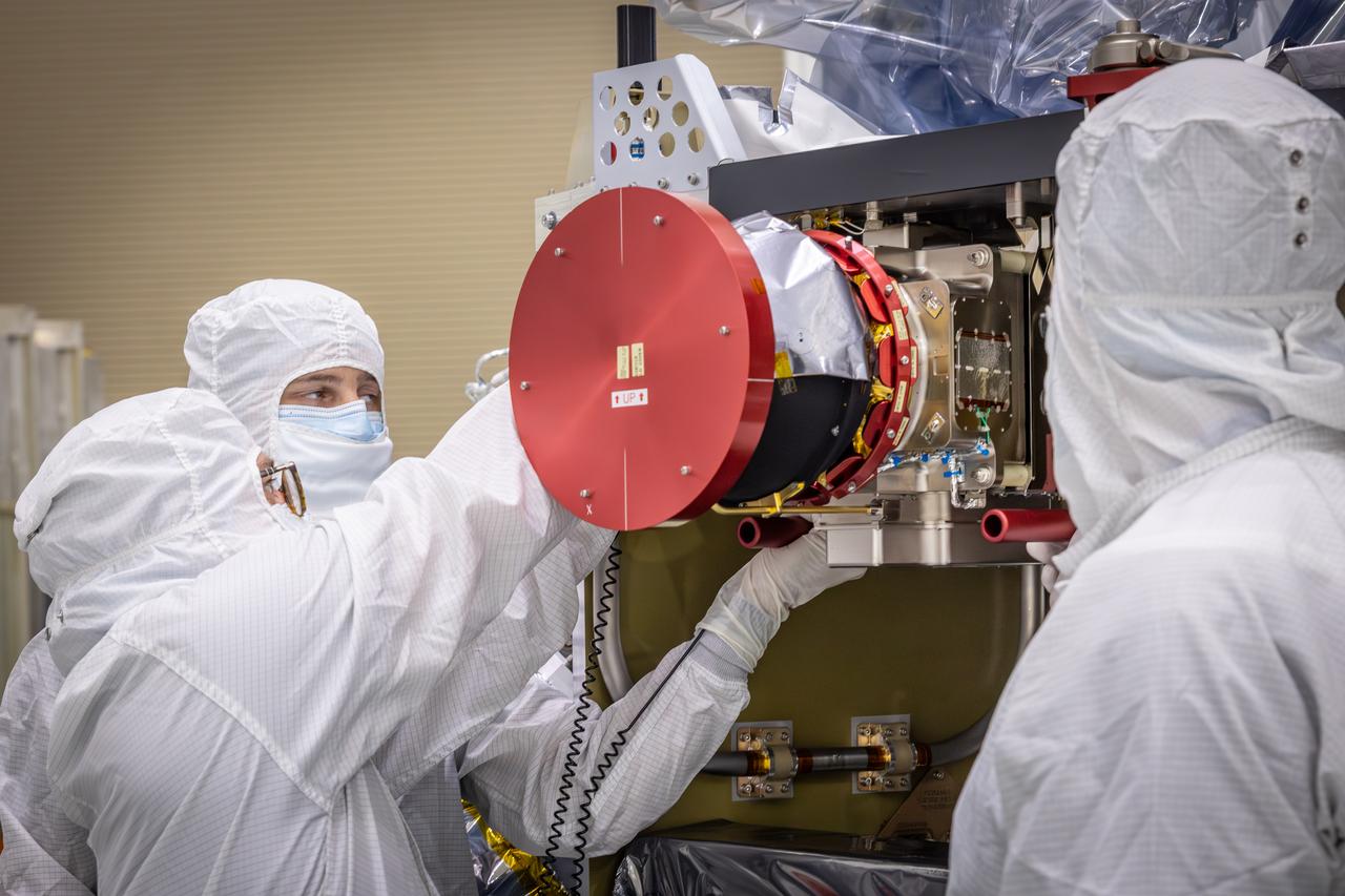
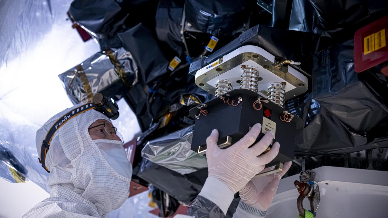
Technicians test the spring-activated door on the Interstellar Dust Experiment (IDEX) instrument of NASA’s IMAP (Interstellar Mapping and Acceleration Probe) observatory inside the high bay at the Astrotech Space Operations Facility near the agency’s Kennedy Space Center in Florida on Tuesday, June 3, 2025. The door will remain closed to protect IDEX from contamination during integration and launch. Once in space, the door will swing open permanently to allow interstellar and interplanetary dust to flow into the instrument for measurement. The IMAP observatory will study how the Sun shapes the boundaries of the heliosphere, the protective bubble around our solar system. Launch is targeted for no earlier than September 2025 aboard a SpaceX Falcon 9 rocket from Launch Complex 39A at NASA Kennedy.
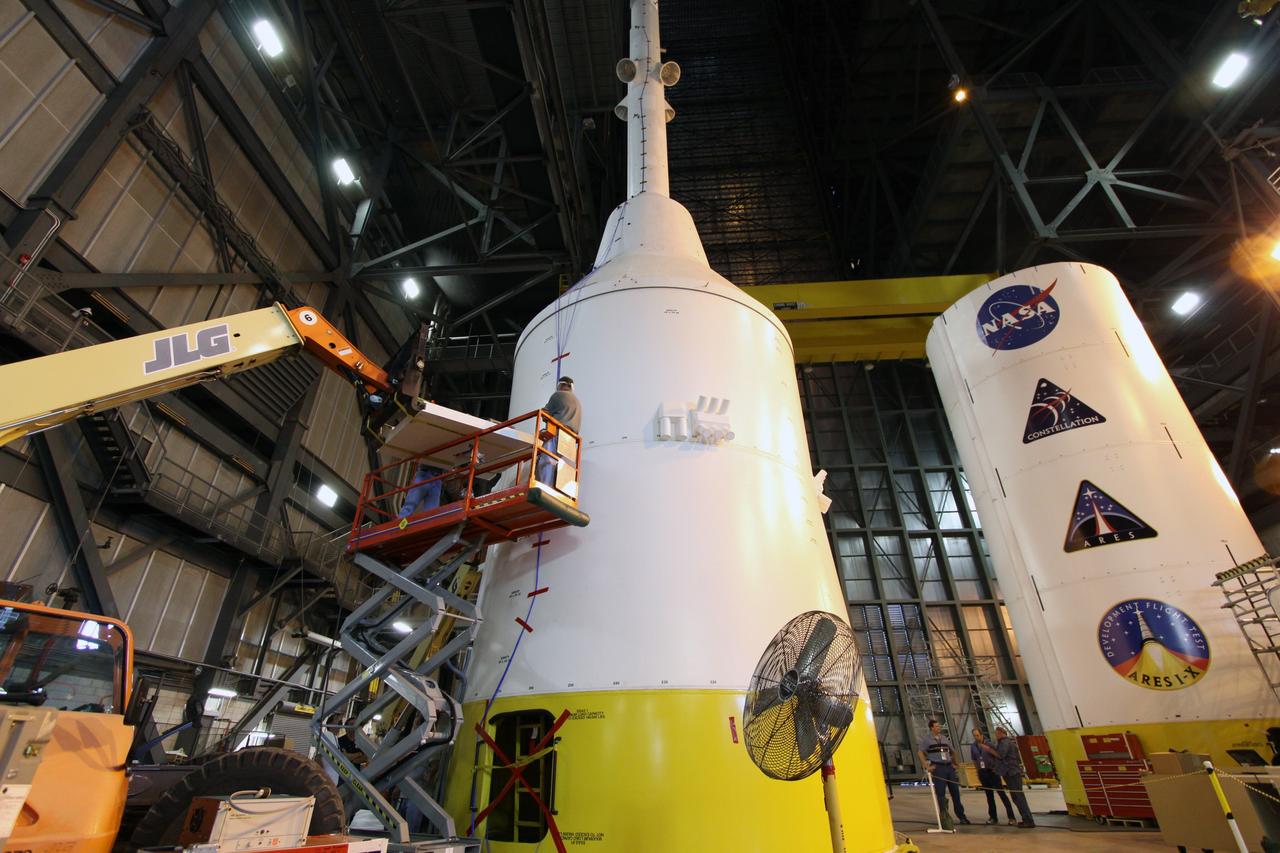
CAPE CANAVERAL, Fla. – In high bay 4 of the Vehicle Assembly Building at NASA's Kennedy Space Center in Florida, technicians place sensors on the top part of the Ares I-X for modal survey testing. The top consists of the launch abort tower, crew module, service module and spacecraft adaptor. Shakers will impose random loads/vibrations to determine the flight test vehicle’s first several bending modes and the strategically located sensors throughout the stacks will measure the amount, acceleration and direction of movement. The purpose of the testing is to confirm that Ares I-X will behave as predicted as it lifts off the pad and powers through the initial stage of flight in a demonstration flight later this year. Photo credit: NASA/Jack Pfaller
CAPE CANAVERAL, Fla. – In high bay 4 of the Vehicle Assembly Building at NASA's Kennedy Space Center in Florida, technicians place sensors on the top part of the Ares I-X for modal survey testing. The top consists of the launch abort tower, crew module, service module and spacecraft adaptor. Shakers will impose random loads/vibrations to determine the flight test vehicle’s first several bending modes and the strategically located sensors throughout the stacks will measure the amount, acceleration and direction of movement. The purpose of the testing is to confirm that Ares I-X will behave as predicted as it lifts off the pad and powers through the initial stage of flight in a demonstration flight later this year. Photo credit: NASA/Jack Pfaller
Technicians test the spring-activated door on the Interstellar Dust Experiment (IDEX) instrument of NASA’s IMAP (Interstellar Mapping and Acceleration Probe) observatory inside the high bay at the Astrotech Space Operations Facility near the agency’s Kennedy Space Center in Florida on Tuesday, June 3, 2025. The door will remain closed to protect IDEX from contamination during integration and launch. Once in space, the door will swing open permanently to allow interstellar and interplanetary dust to flow into the instrument for measurement. The IMAP observatory will study how the Sun shapes the boundaries of the heliosphere, the protective bubble around our solar system. Launch is targeted for no earlier than September 2025 aboard a SpaceX Falcon 9 rocket from Launch Complex 39A at NASA Kennedy.
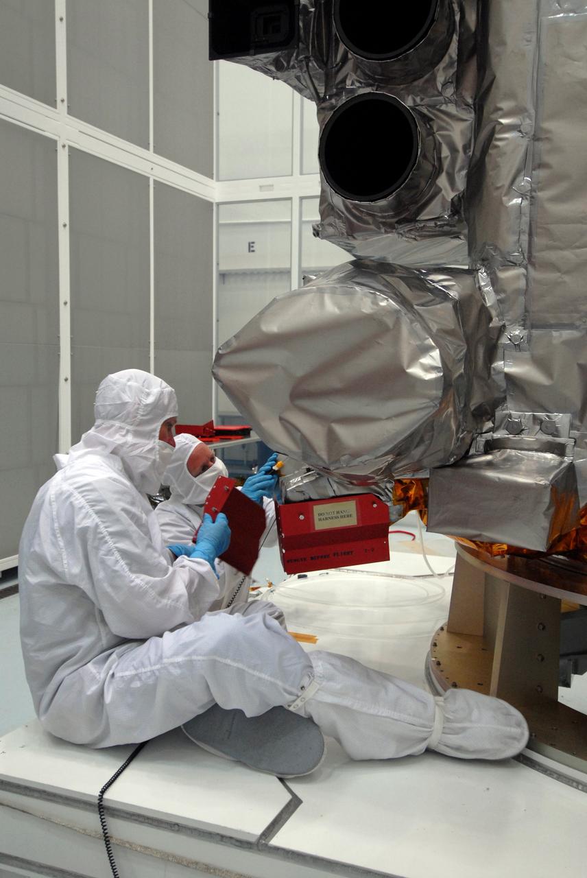
CAPE CANAVERAL, Fla. – At Astrotech Space Operations in Titusville, Fla., technicians remove red-tag items from the Lunar Reconnaissance Orbiter, or LRO, before flight. The LRO will be mated with NASA's Lunar CRater Observation and Sensing Satellite, known as LCROSS, spacecraft. Instruments on the LRO seen here are the LEND (bottom) that will measure the flux of neutrons from the moon and the LROC (above it), a narrow angle camera that will provide panchromatic images. The satellite's primary mission is to search for water ice on the moon in a permanently shadowed crater near one of the lunar poles. LCROSS is a low-cost, accelerated-development, companion mission to NASA's Lunar Reconnaissance Orbiter, or LRO. LCROSS and LRO are the first missions in NASA's plan to return humans to the moon and begin establishing a lunar outpost by 2020. Launch is targeted for no earlier than June 2 from Cape Canaveral Air Force Station in Florida. Photo credit: NASA/Jack Pfaller

Technicians test the spring-activated door on the Interstellar Dust Experiment (IDEX) instrument of NASA’s IMAP (Interstellar Mapping and Acceleration Probe) observatory inside the high bay at the Astrotech Space Operations Facility near the agency’s Kennedy Space Center in Florida on Tuesday, June 3, 2025. The door will remain closed to protect IDEX from contamination during integration and launch. Once in space, the door will swing open permanently to allow interstellar and interplanetary dust to flow into the instrument for measurement. The IMAP observatory will study how the Sun shapes the boundaries of the heliosphere, the protective bubble around our solar system. Launch is targeted for no earlier than September 2025 aboard a SpaceX Falcon 9 rocket from Launch Complex 39A at NASA Kennedy.
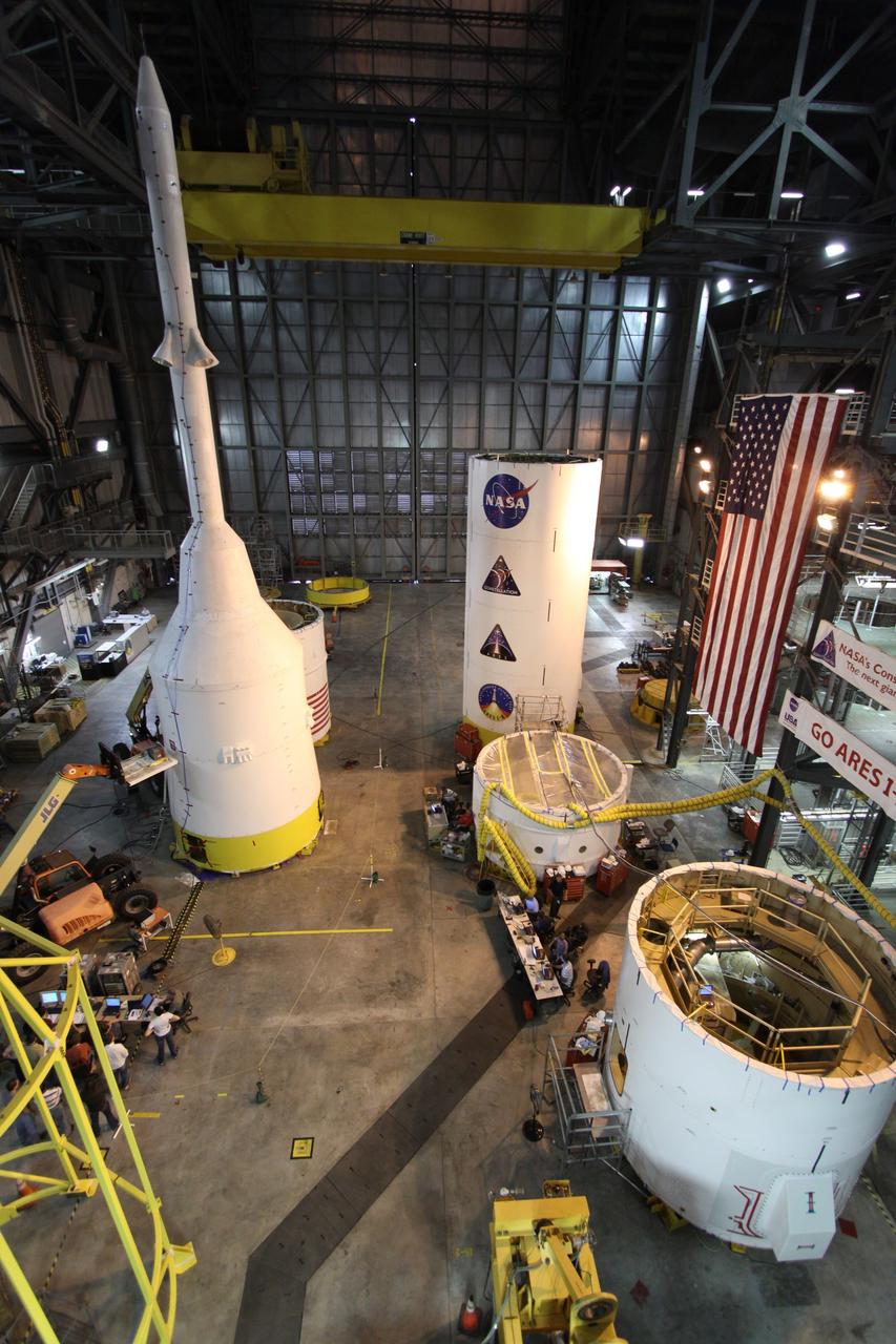
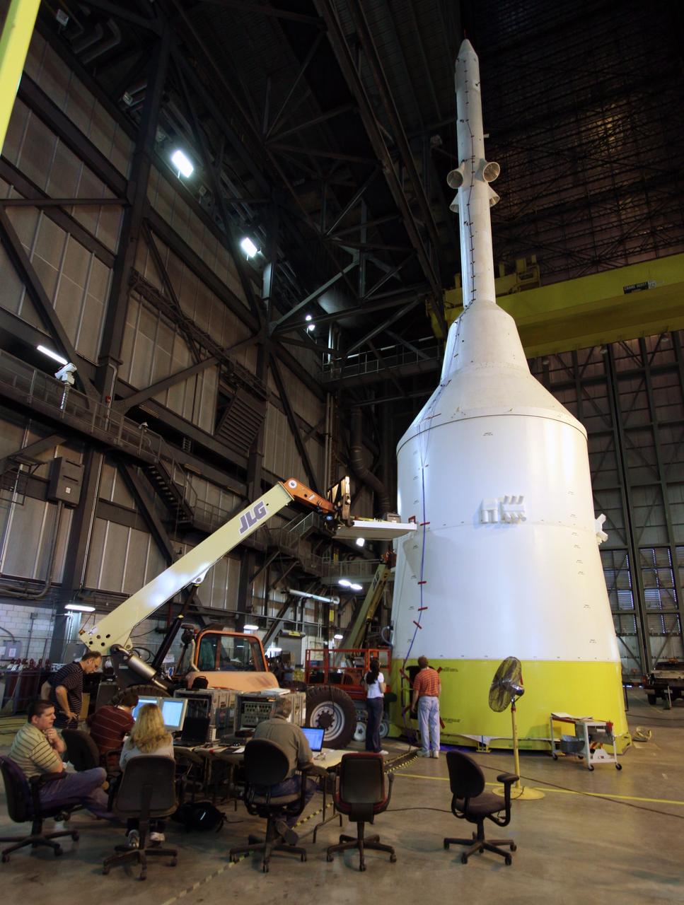
CAPE CANAVERAL, Fla. – In high bay 4 of the Vehicle Assembly Building at NASA's Kennedy Space Center in Florida, technicians begin the modal survey testing on the top part of the Ares I-X (upper left) after sensors were placed on the stack. The top consists of the launch abort tower, crew module, service module and spacecraft adaptor. Other segments are stacked nearby. Shakers will impose random loads/vibrations to determine the flight test vehicle’s first several bending modes and the strategically located sensors throughout the stacks will measure the amount, acceleration and direction of movement. The purpose of the testing is to confirm that Ares I-X will behave as predicted as it lifts off the pad and powers through the initial stage of flight in a demonstration flight later this year. Photo credit: NASA/Jack Pfaller
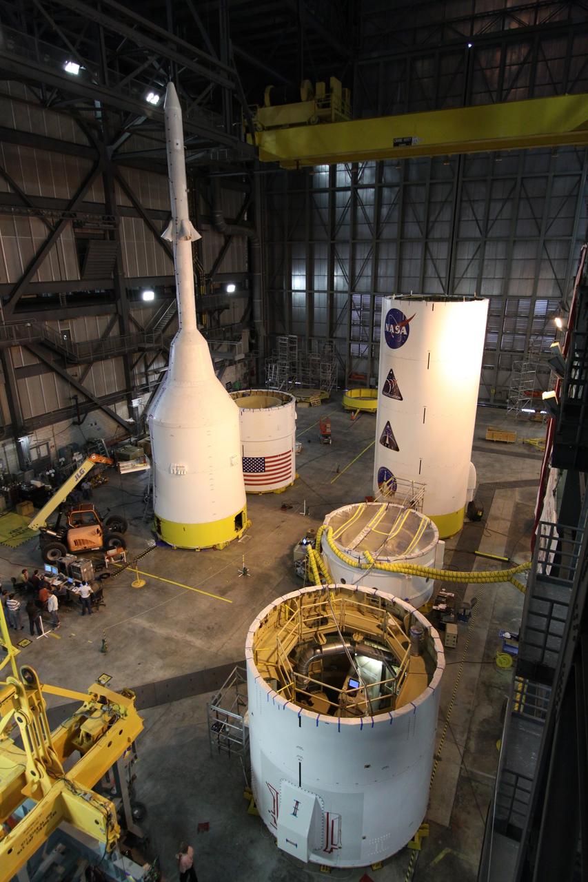
CAPE CANAVERAL, Fla. – In high bay 4 of the Vehicle Assembly Building at NASA's Kennedy Space Center in Florida, the top part of the Ares I-X (upper left) undergoes modal survey testing after sensors were placed on the stack. The top consists of the launch abort tower, crew module, service module and spacecraft adaptor. Other segments are stacked nearby. Shakers will impose random loads/vibrations to determine the flight test vehicle’s first several bending modes and the strategically located sensors throughout the stacks will measure the amount, acceleration and direction of movement. The purpose of the testing is to confirm that Ares I-X will behave as predicted as it lifts off the pad and powers through the initial stage of flight in a demonstration flight later this year. Photo credit: NASA/Jack Pfaller
Technicians test the spring-activated door on the Interstellar Dust Experiment (IDEX) instrument of NASA’s IMAP (Interstellar Mapping and Acceleration Probe) observatory inside the high bay at the Astrotech Space Operations Facility near the agency’s Kennedy Space Center in Florida on Tuesday, June 3, 2025. The door will remain closed to protect IDEX from contamination during integration and launch. Once in space, the door will swing open permanently to allow interstellar and interplanetary dust to flow into the instrument for measurement. The IMAP observatory will study how the Sun shapes the boundaries of the heliosphere, the protective bubble around our solar system. Launch is targeted for no earlier than September 2025 aboard a SpaceX Falcon 9 rocket from Launch Complex 39A at NASA Kennedy.

The National Aeronautics and Space Administration (NASA) Lewis Research Center tested 16 commercially-manufactured electric vehicles, including these, during the mid-1970s. Lewis and the Energy Research and Development Administration (ERDA) engaged in several energy-related programs in the mid-1970s, including the Electric Vehicle Project. NASA and ERDA undertook the program in 1976 to determine the state of the current electric vehicle technology. The tests were primarily conducted on a 7.5-mile track at the Transportation Research Center located approximately 160 miles southwest of Cleveland, Ohio. Some of the vehicles had analog data recording systems to measure the battery during operation and sensors to determine speed and distance. The tests analyzed the vehicle’s range, acceleration, coast-down, braking, and energy consumption. From left to right: RIPP-Electric, EVA Contactor, Otis P-500, C.H. Waterman DAF, Zagato Elcar, unknown, Sebring-Vanguard Citicar, and Hattronic Minivan

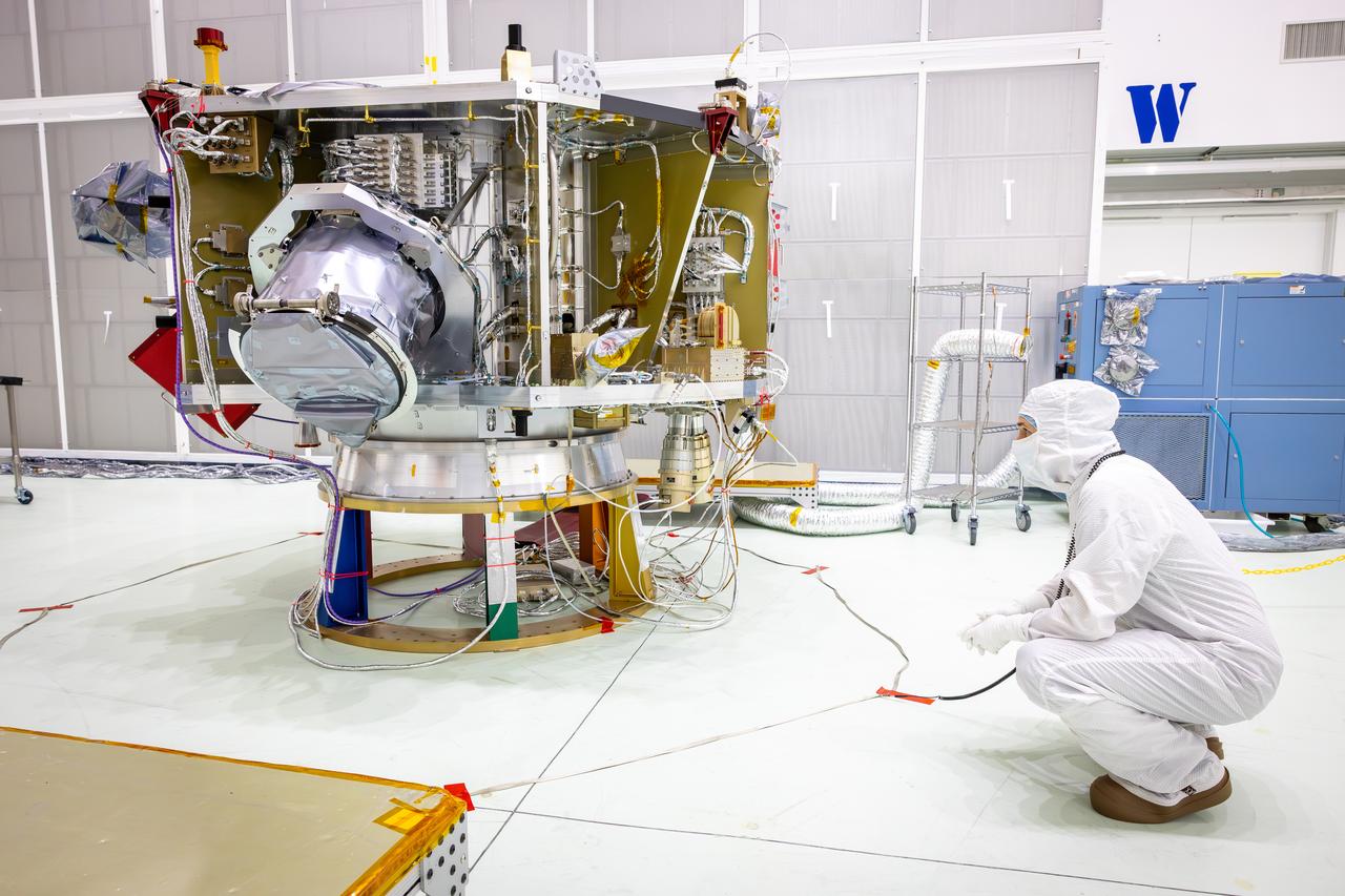
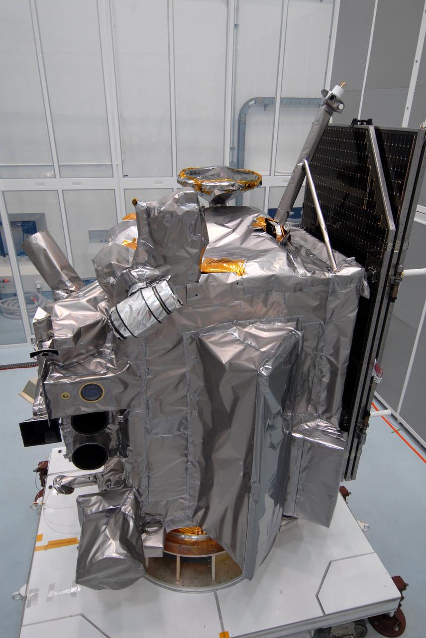
One of two rideshare spacecraft on NASA’s IMAP (Interstellar Mapping and Acceleration Probe) mission, the National Oceanic and Atmospheric Administration’s (NOAA) Space Weather Follow On–Lagrange 1 (SWFO-L1) observatory sits on a spacecraft dolly in a high bay inside Astrotech Space Operations Facility near the agency’s Kennedy Space Center in Florida during a NASA-hosted media day on Thursday, Aug. 28, 2025. The missions, along with NASA’s exosphere-studying Carruthers Geocorona Observatory, will orbit the Sun near Lagrange point 1, about one million miles from Earth, where SWFO-L1 will monitor the Sun and near-Earth environment using a suite of instruments that provide real-time measurements of solar activity.

Technicians test the spring-activated door on the Interstellar Dust Experiment (IDEX) instrument of NASA’s IMAP (Interstellar Mapping and Acceleration Probe) observatory inside the high bay at the Astrotech Space Operations Facility near the agency’s Kennedy Space Center in Florida on Tuesday, June 3, 2025. The door will remain closed to protect IDEX from contamination during integration and launch. Once in space, the door will swing open permanently to allow interstellar and interplanetary dust to flow into the instrument for measurement. The IMAP observatory will study how the Sun shapes the boundaries of the heliosphere, the protective bubble around our solar system. Launch is targeted for no earlier than September 2025 aboard a SpaceX Falcon 9 rocket from Launch Complex 39A at NASA Kennedy.
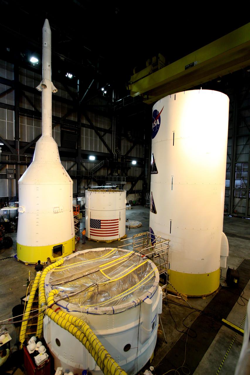
CAPE CANAVERAL, Fla. – In high bay 4 of the Vehicle Assembly Building at NASA's Kennedy Space Center in Florida, the top part of the Ares I-X (upper left) is ready for modal survey testing. The top consists of the launch abort tower, crew module, service module and spacecraft adaptor. Other segments are stacked nearby. Shakers will impose random loads/vibrations to determine the flight test vehicle’s first several bending modes and the strategically located sensors throughout the stacks will measure the amount, acceleration and direction of movement. The purpose of the testing is to confirm that Ares I-X will behave as predicted as it lifts off the pad and powers through the initial stage of flight in a demonstration flight later this year. Photo credit: NASA/Jack Pfaller

One of two rideshare spacecraft on NASA’s IMAP (Interstellar Mapping and Acceleration Probe) mission, the National Oceanic and Atmospheric Administration’s (NOAA) Space Weather Follow On–Lagrange 1 (SWFO-L1) observatory sits on a spacecraft dolly in a high bay inside Astrotech Space Operations Facility near the agency’s Kennedy Space Center in Florida during a NASA-hosted media day on Thursday, Aug. 28, 2025. The missions, along with NASA’s exosphere-studying Carruthers Geocorona Observatory, will orbit the Sun near Lagrange point 1, about one million miles from Earth, where SWFO-L1 will monitor the Sun and near-Earth environment using a suite of instruments that provide real-time measurements of solar activity.
Technicians test the spring-activated door on the Interstellar Dust Experiment (IDEX) instrument of NASA’s IMAP (Interstellar Mapping and Acceleration Probe) observatory inside the high bay at the Astrotech Space Operations Facility near the agency’s Kennedy Space Center in Florida on Tuesday, June 3, 2025. The door will remain closed to protect IDEX from contamination during integration and launch. Once in space, the door will swing open permanently to allow interstellar and interplanetary dust to flow into the instrument for measurement. The IMAP observatory will study how the Sun shapes the boundaries of the heliosphere, the protective bubble around our solar system. Launch is targeted for no earlier than September 2025 aboard a SpaceX Falcon 9 rocket from Launch Complex 39A at NASA Kennedy.
Technicians test the spring-activated door on the Interstellar Dust Experiment (IDEX) instrument of NASA’s IMAP (Interstellar Mapping and Acceleration Probe) observatory inside the high bay at the Astrotech Space Operations Facility near the agency’s Kennedy Space Center in Florida on Tuesday, June 3, 2025. The door will remain closed to protect IDEX from contamination during integration and launch. Once in space, the door will swing open permanently to allow interstellar and interplanetary dust to flow into the instrument for measurement. The IMAP observatory will study how the Sun shapes the boundaries of the heliosphere, the protective bubble around our solar system. Launch is targeted for no earlier than September 2025 aboard a SpaceX Falcon 9 rocket from Launch Complex 39A at NASA Kennedy.
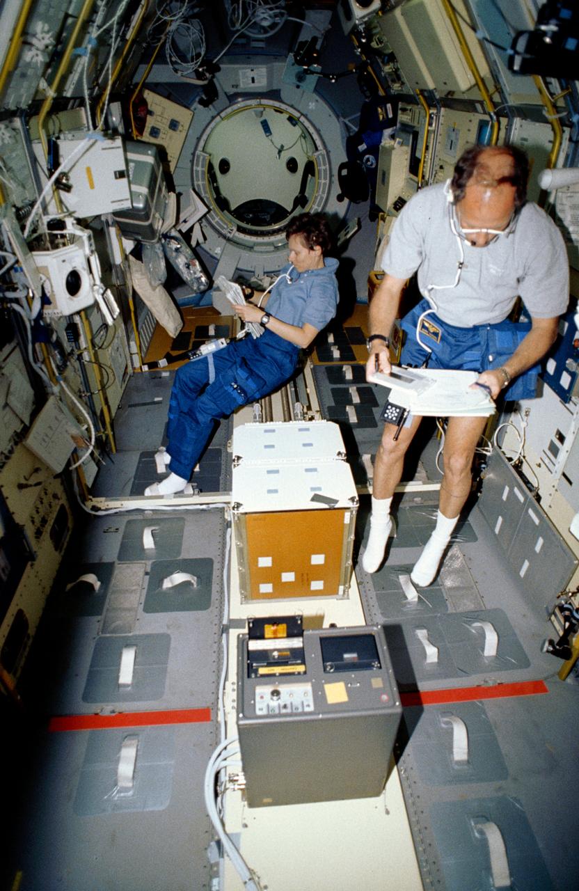
STS042-11-016 (30 Jan 1992) --- Astronaut Norman E. Thagard, STS-42 missions specialist and payload commander, and payload specialist Roberta L. Bondar are busily engaged with experiments in the International Microgravity Laboratory 1 (IML-1) Spacelab module. Bondar reads a checklist near the Rack 5 Biorack and glovebox while Thagard performs a VCR tape change-out. The Space Acceleration Measurement System (SAMS) (foreground) and shuttle middeck lockers are secured in IML-1's center aisle. In the background the open hatch and Spacelab tunnel interior are visible. Crewmembers enter and exit the IML-1 module via the Spacelab tunnel which connects to Discovery's, Orbiter Vehicle (OV) 103's, airlock.
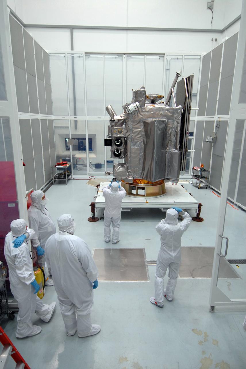
CAPE CANAVERAL, Fla. – At Astrotech Space Operations in Titusville, Fla., technicians photograph the Lunar Reconnaissance Orbiter, or LRO, during closeout before its mating with NASA's Lunar CRater Observation and Sensing Satellite, known as LCROSS, spacecraft. Instruments on the LRO include the LEND that will measure the flux of neutrons from the moon; the LROC, a narrow angle camera that will provide panchromatic images; the LOLA, which will provide a precise global lunar topographic model and geodetic grid; and top right, the DIVINER, which will measure lunar surface temperatures at scales that provide essential information for future surface operations and exploration; and at top, the CRaTER, which will characterize the global lunar radiation environment and its biological impacts. At right is the solar panel. The satellite's primary mission is to search for water ice on the moon in a permanently shadowed crater near one of the lunar poles. LCROSS is a low-cost, accelerated-development, companion mission to NASA's Lunar Reconnaissance Orbiter, or LRO. LCROSS and LRO are the first missions in NASA's plan to return humans to the moon and begin establishing a lunar outpost by 2020. Launch is targeted for no earlier than June 2 from Cape Canaveral Air Force Station in Florida. Photo credit: NASA/Jack Pfaller
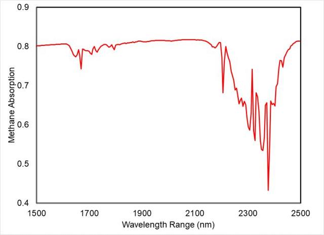
This spectral "fingerprint" of methane was produced from data taken during a September 2023 test at NASA's Jet Propulsion Laboratory in Southern California of a state-of-the-art imaging spectrometer that will measure the greenhouse gases methane and carbon dioxide from space. The instrument measures hundreds of wavelengths of light reflected by Earth's surface and absorbed by gases in the planet's atmosphere. Different compounds absorb different wavelengths of light, leaving a kind of spectral fingerprint that the imaging spectrometer can identify. These infrared fingerprints, invisible to the human eye, can pinpoint and quantify strong greenhouse gas emissions, and accelerate mitigation efforts. Before the imaging spectrometer was shipped from JPL to Planet Labs PBC in San Francisco, where it will be integrated into a Tanager satellite, there was a rare opportunity to use a sample of methane to test the completed instrument while it was in a vacuum chamber. The test was successful, and the imaging spectrometer produced this clear spectral fingerprint of methane (appearing as a red line in the graph). Designed and built by JPL, imaging spectrometer will be part of an effort led by the nonprofit Carbon Mapper organization to collect data on greenhouse gas point-source emissions. The information will help locate and quantify "super-emitters" – the small percentage of individual sources responsible for a significant fraction of methane and carbon dioxide emissions around the world. https://photojournal.jpl.nasa.gov/catalog/PIA26095
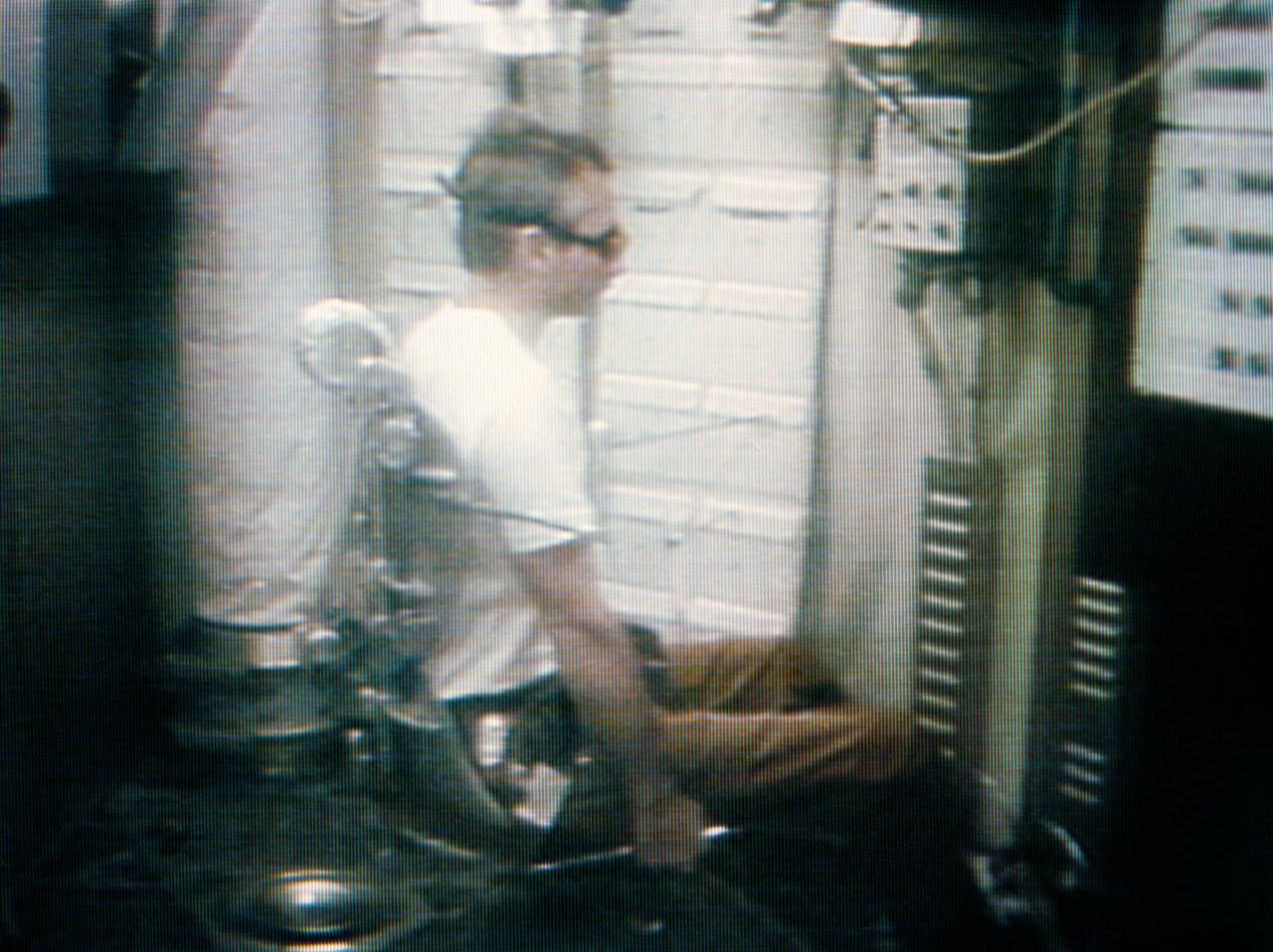
S73-34171 (9 Aug. 1973) --- Scientist-astronaut Owen K. Garriott, Skylab 3 science pilot, serves as test subject for the Skylab ?Human Vestibular Function? M131 Experiment, as seen in this photographic reproduction taken from a television transmission made by a color TV camera aboard the Skylab space station in Earth orbit. The objectives of the Skylab M131 experiment are to obtain data pertinent to establishing the validity of measurements of specific behavioral/physiological responses influenced by vestibular activity under one-g and zero-g conditions; to determine man?s adaptability to unusual vestibular conditions and predict habitability of future spacecraft conditions involving reduced gravity and Coriollis forces; and to measure the accuracy and variability in man?s judgment of spatial coordinates based on atypical gravity receptor cues and inadequate visual cures. Dr. Garriott is seated in the experiment?s litter chair which can rotate the test subject at predetermined rotational velocity or programmed acceleration/decelerational profile. Photo credit: NASA
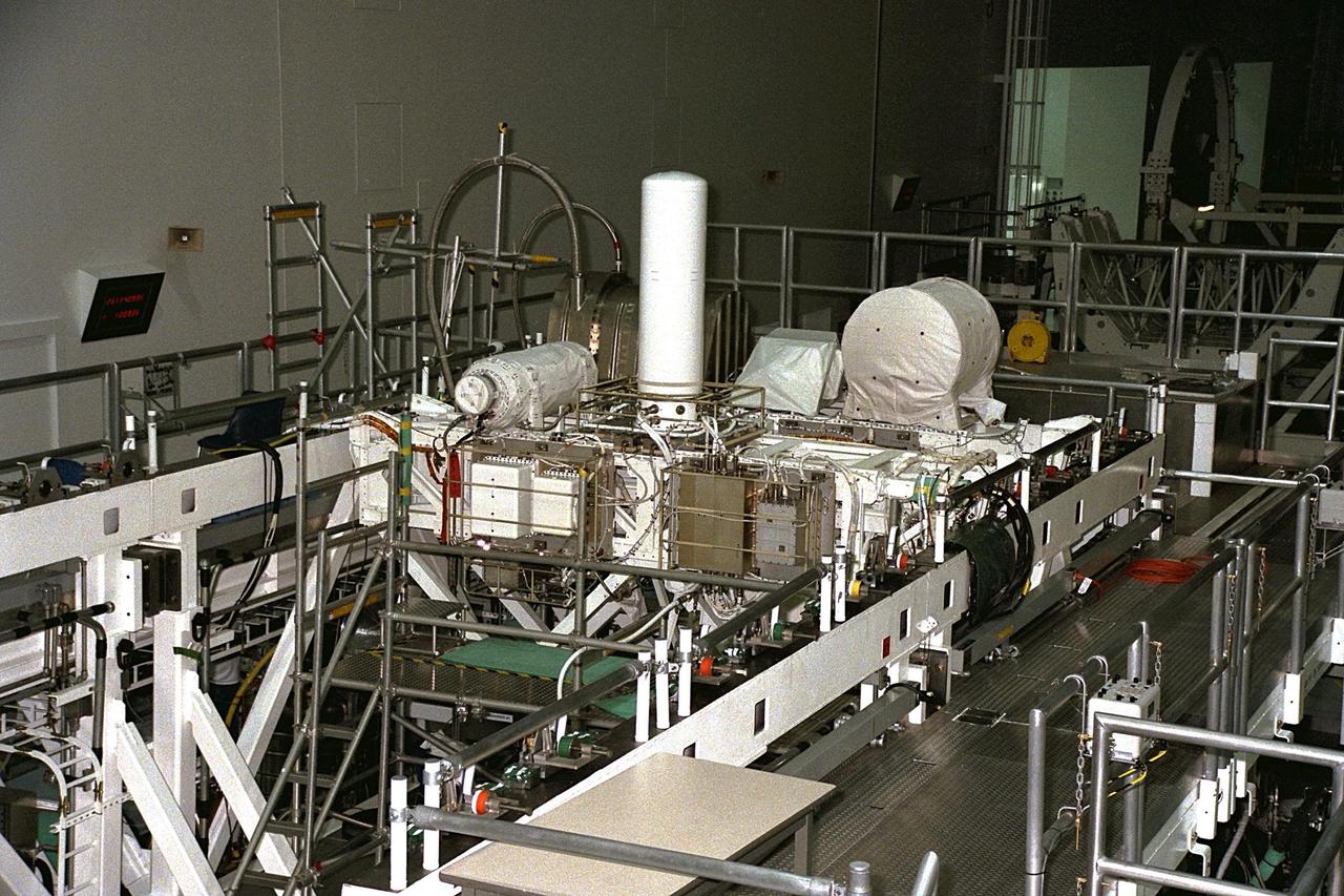
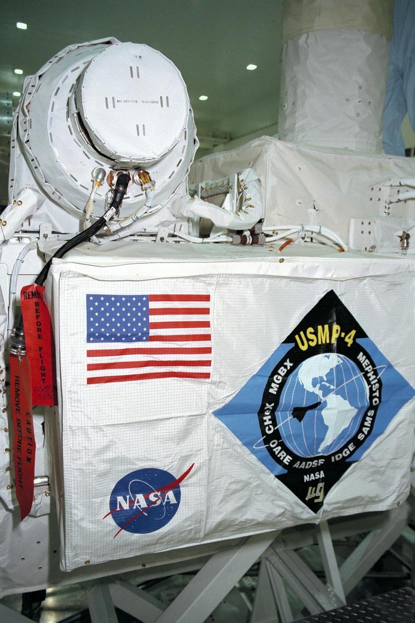
United States Microgravity Payload-4 (USMP-4) experiments are prepared to be flown on Space Shuttle mission STS-87 in the Space Station Processing Facility at Kennedy Space Center (KSC). Seen at right in the circular white cover is the Isothermal Dendritic Growth Experiment (IDGE), which will be used to study the dendritic solidification of molten materials in the microgravity environment. The large white vertical cylinder in the center of the photo is the Advanced Automated Directional Solidification Furnace (AADSF) and the horizontal tube to the left of it is MEPHISTO, a French acronym for a cooperative American-French investigation of the fundamentals of crystal growth. Just below MEPHISTO is the Space Acceleration Measurement System, or SAMS, which measures the microgravity conditions in which the experiments are conducted. The The metallic breadbox-like structure behind the AADSF is the Confined Helium Experiment (CHeX) that will study one of the basic influences on the behavior and properties of materials by using liquid helium confined between solid surfaces and microgravity. All of these experiments are scheduled for launch aboard STS-87 on Nov. 19 from KSC

CAPE CANAVERAL, Fla. – At Astrotech Space Operations in Titusville, Fla., technicians perform black light inspection on the Lunar Reconnaissance Orbiter, or LRO, looking for possible contamination. Instruments on the LRO include the LEND that will measure the flux of neutrons from the moon; the LROC, a narrow angle camera that will provide panchromatic images; the LOLA, which will provide a precise global lunar topographic model and geodetic grid; and top right, the DIVINER, which will measure lunar surface temperatures at scales that provide essential information for future surface operations and exploration; and at top, the CRaTER, which will characterize the global lunar radiation environment and its biological impacts. The satellite's primary mission is to search for water ice on the moon in a permanently shadowed crater near one of the lunar poles. LCROSS is a low-cost, accelerated-development, companion mission to NASA's Lunar Reconnaissance Orbiter, or LRO. LCROSS and LRO are the first missions in NASA's plan to return humans to the moon and begin establishing a lunar outpost by 2020. Launch is targeted for no earlier than June 2 from Cape Canaveral Air Force Station in Florida. Photo credit: NASA/Jack Pfaller
CAPE CANAVERAL, Fla. – Another view of the Lunar Reconnaissance Orbiter, or LRO, at Astrotech Space Operations in Titusville, Fla., during closeout before its mating with NASA's Lunar CRater Observation and Sensing Satellite, known as LCROSS, spacecraft. Instruments seen, at left, are (from bottom) the LEND that will measure the flux of neutrons from the moon; the LROC, a narrow angle camera that will provide panchromatic images; the LOLA, which will provide a precise global lunar topographic model and geodetic grid; and top right, the DIVINER, which will measure lunar surface temperatures at scales that provide essential information for future surface operations and exploration; and at top, the CRaTER, which will characterize the global lunar radiation environment and its biological impacts. At right is the solar panel. The satellite's primary mission is to search for water ice on the moon in a permanently shadowed crater near one of the lunar poles. LCROSS is a low-cost, accelerated-development, companion mission to NASA's Lunar Reconnaissance Orbiter, or LRO. LCROSS and LRO are the first missions in NASA's plan to return humans to the moon and begin establishing a lunar outpost by 2020. Launch is targeted for no earlier than June 2 from Cape Canaveral Air Force Station in Florida. Photo credit: NASA/Jack Pfaller
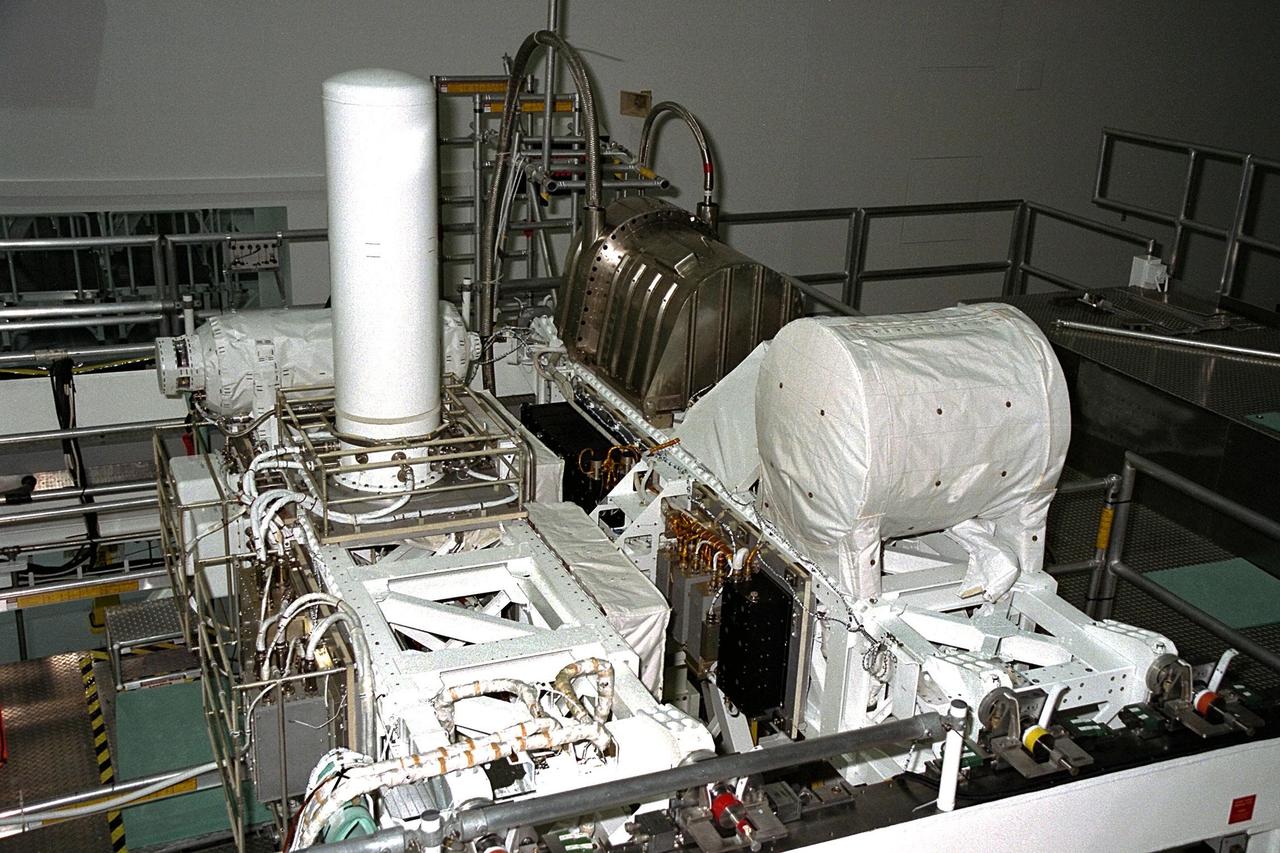
United States Microgravity Payload-4 (USMP-4) experiments are prepared to be flown on Space Shuttle mission STS-87 in the Space Station Processing Facility at Kennedy Space Center (KSC). Seen in the foreground at right is the Isothermal Dendritic Growth Experiment (IDGE), which will be used to study the dendritic solidification of molten materials in the microgravity environment. The metallic breadbox-like structure behind the IDGE is the Confined Helium Experiment (CHeX) that will study one of the basic influences on the behavior and properties of materials by using liquid helium confined between solid surfaces and microgravity. The large white vertical cylinder at left is the Advanced Automated Directional Solidification Furnace (AADSF) and the horizontal tube behind it is MEPHISTO, the French acronym for a cooperative American-French investigation of the fundamentals of crystal growth. Just below the left end of MEPHISTO is the Space Acceleration Measurement System, or SAMS, which measures the microgravity conditions in which the experiments are conducted. All of these experiments are scheduled for launch aboard STS-87 on Nov. 19 from KSC
CAPE CANAVERAL, Fla. – At Astrotech Space Operations in Titusville, Fla., technicians are closing out the Lunar Reconnaissance Orbiter, or LRO, before its mating with NASA's Lunar CRater Observation and Sensing Satellite, known as LCROSS, spacecraft. Instruments seen at far left are (from bottom), the LEND that will measure the flux of neutrons from the moon; the LROC, a narrow angle camera that will provide panchromatic images; the LOLA, which will provide a precise global lunar topographic model and geodetic grid; and top right, the DIVINER, which will measure lunar surface temperatures at scales that provide essential information for future surface operations and exploration; and at top, the CRaTER, which will characterize the global lunar radiation environment and its biological impacts. The satellite's primary mission is to search for water ice on the moon in a permanently shadowed crater near one of the lunar poles. LCROSS is a low-cost, accelerated-development, companion mission to NASA's Lunar Reconnaissance Orbiter, or LRO. LCROSS and LRO are the first missions in NASA's plan to return humans to the moon and begin establishing a lunar outpost by 2020. Launch is targeted for no earlier than June 2 from Cape Canaveral Air Force Station in Florida. Photo credit: NASA/Jack Pfaller

CAPE CANAVERAL, Fla. – At Astrotech Space Operations in Titusville, Fla., technicians perform black light inspection on the Lunar Reconnaissance Orbiter, or LRO, looking for possible contamination. Instruments on the LRO include the LEND that will measure the flux of neutrons from the moon; the LROC, a narrow angle camera that will provide panchromatic images; the LOLA, which will provide a precise global lunar topographic model and geodetic grid; and top right, the DIVINER, which will measure lunar surface temperatures at scales that provide essential information for future surface operations and exploration; and at top, the CRaTER, which will characterize the global lunar radiation environment and its biological impacts. The satellite's primary mission is to search for water ice on the moon in a permanently shadowed crater near one of the lunar poles. LCROSS is a low-cost, accelerated-development, companion mission to NASA's Lunar Reconnaissance Orbiter, or LRO. LCROSS and LRO are the first missions in NASA's plan to return humans to the moon and begin establishing a lunar outpost by 2020. Launch is targeted for no earlier than June 2 from Cape Canaveral Air Force Station in Florida. Photo credit: NASA/Jack Pfaller
CAPE CANAVERAL, Fla. – At Astrotech Space Operations in Titusville, Fla., technicians begin closeout on the Lunar Reconnaissance Orbiter, or LRO, before its mating with NASA's Lunar CRater Observation and Sensing Satellite, known as LCROSS, spacecraft. Instruments seen are (from bottom), the LEND that will measure the flux of neutrons from the moon; the LROC, a narrow angle camera that will provide panchromatic images; the LOLA, which will provide a precise global lunar topographic model and geodetic grid; and top right, the DIVINER, which will measure lunar surface temperatures at scales that provide essential information for future surface operations and exploration; and at top, the CRaTER, which will characterize the global lunar radiation environment and its biological impacts. The satellite's primary mission is to search for water ice on the moon in a permanently shadowed crater near one of the lunar poles. LCROSS is a low-cost, accelerated-development, companion mission to NASA's Lunar Reconnaissance Orbiter, or LRO. LCROSS and LRO are the first missions in NASA's plan to return humans to the moon and begin establishing a lunar outpost by 2020. Launch is targeted for no earlier than June 2 from Cape Canaveral Air Force Station in Florida. Photo credit: NASA/Jack Pfaller