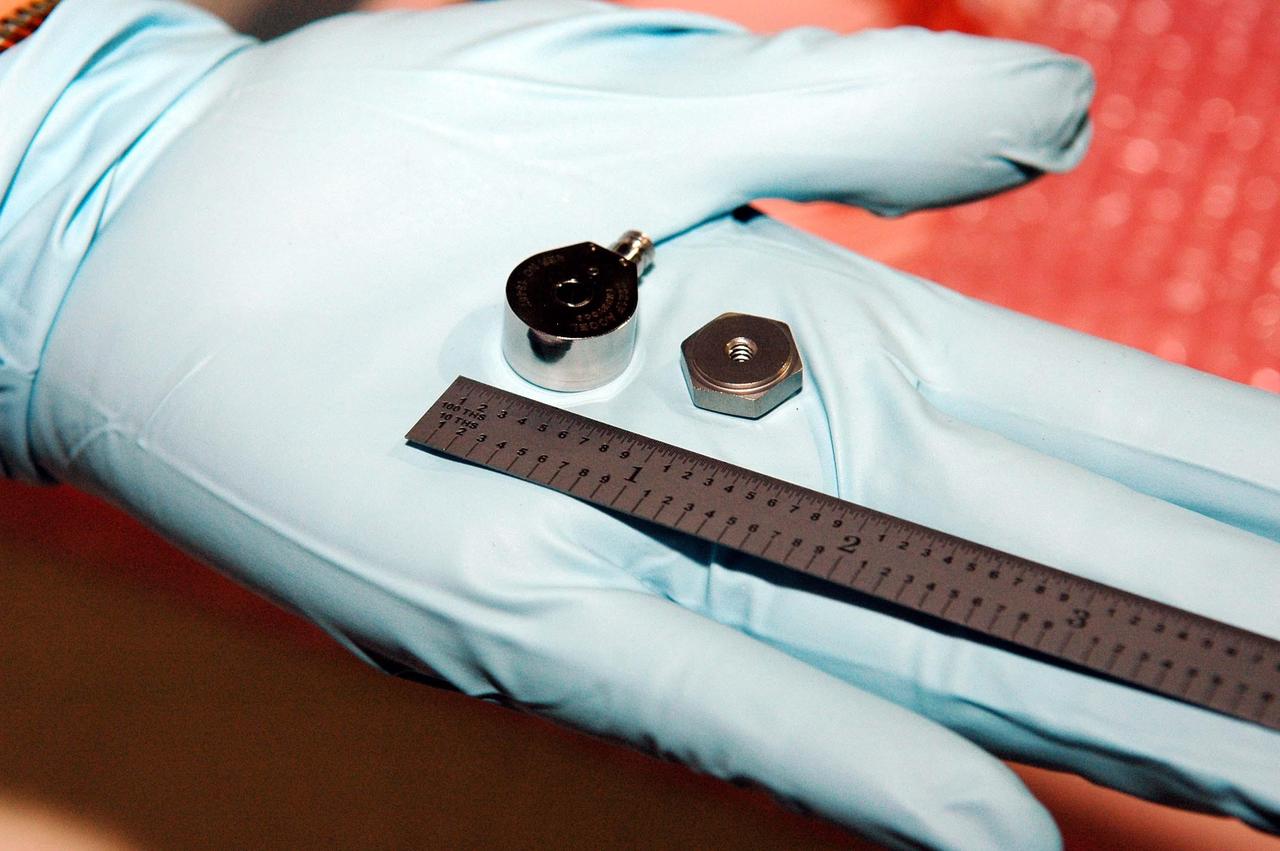
KENNEDY SPACE CENTER, FLA. - This photo shows the size of the sensors being placed on the wing leading edge of orbiter Discovery. In her hand, United Space Alliance technician Lisa Campbell holds an accelerometer (left), which will eventually be installed on a mounting nut. The sensors are part of the Wing Leading Edge Impact Detection System, a new safety measure added for all future Space Shuttle missions. The system also includes accelerometers that monitor the orbiter's wings for debris impacts during launch and while in orbit. There are 22 temperature sensors and 66 accelerometers on each wing. Sensor data will flow from the wing to the crew compartment, where it will be transmitted to Earth.
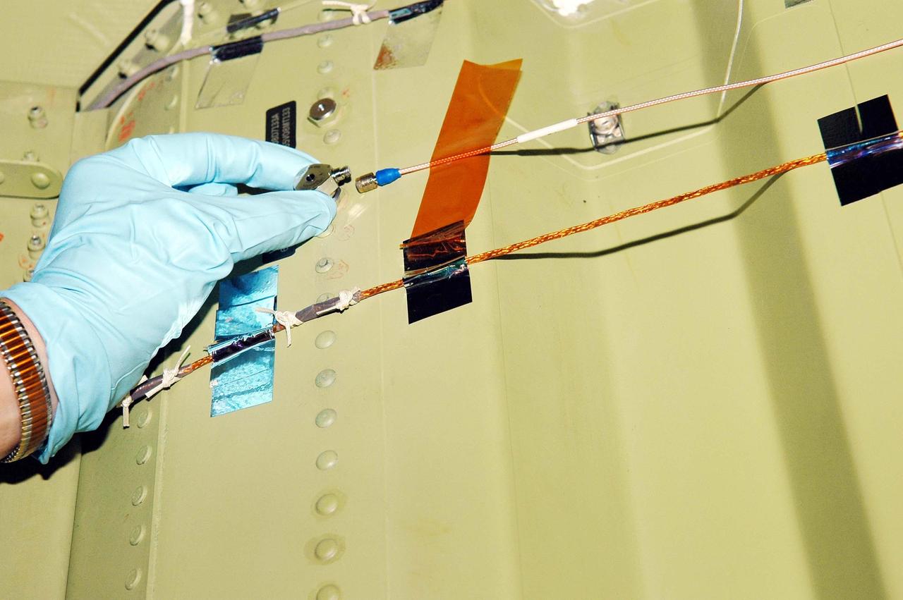
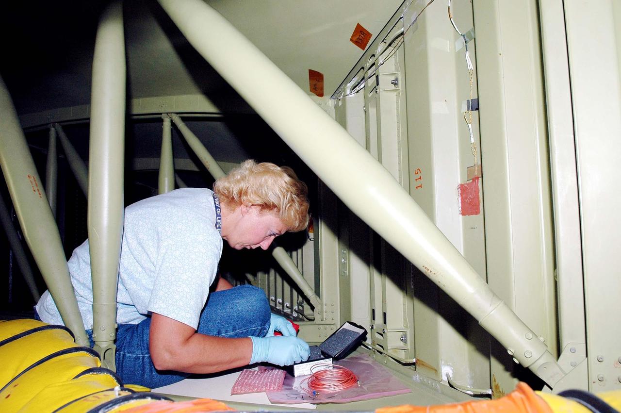
KENNEDY SPACE CENTER, FLA. - In an installation demonstration in the Orbiter Processing Facility, a sensor is placed on the wing leading edge of orbiter Discovery. The sensors are part of the Wing Leading Edge Impact Detection System, a new safety measure added for all future Space Shuttle missions. The system also includes accelerometers that monitor the orbiter's wings for debris impacts during launch and while in orbit. There are 22 temperature sensors and 66 accelerometers on each wing. Sensor data will flow from the wing to the crew compartment, where it will be transmitted to Earth.

KENNEDY SPACE CENTER, FLA. - In an installation demonstration the Orbiter Processing Facility, a sensor is placed on the wing leading edge of orbiter Discovery. The sensors are part of the Wing Leading Edge Impact Detection System, a new safety measure added for all future Space Shuttle missions. The system also includes accelerometers that monitor the orbiter's wings for debris impacts during launch and while in orbit. There are 22 temperature sensors and 66 accelerometers on each wing. Sensor data will flow from the wing to the crew compartment, where it will be transmitted to Earth.
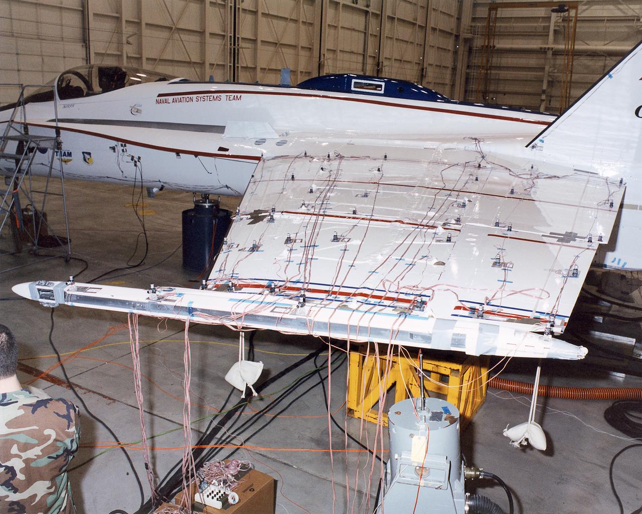
The upper wing surfaces of the Active Aeroelastic Wing F/A-18 test aircraft are covered with accelerometers and other sensors during ground vibration tests at NASA Dryden Flight Research Center.
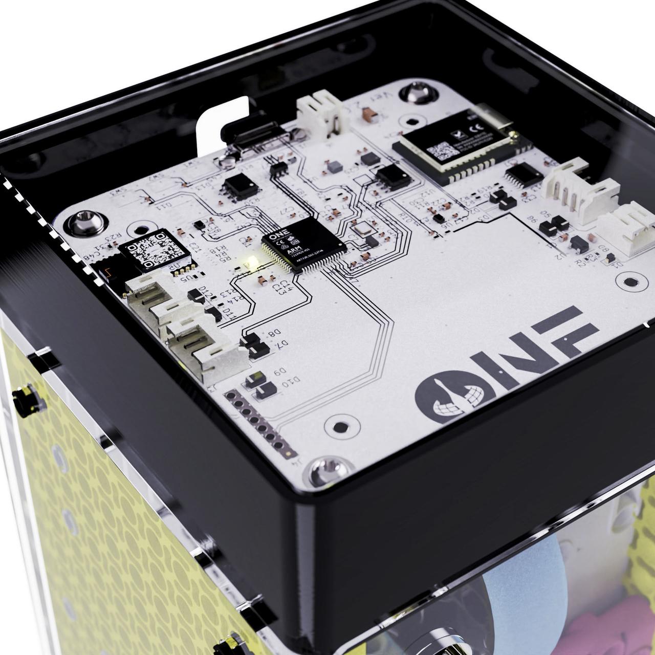
jsc2023e053550 (7/27/2023) --- The denMACH ONE IoT modem complete with inbuilt sensors to measure temperature, humidity, CO2, barometric pressure, compass points, accelerometer, GPS. Image courtesy SpaceTech denMACH.
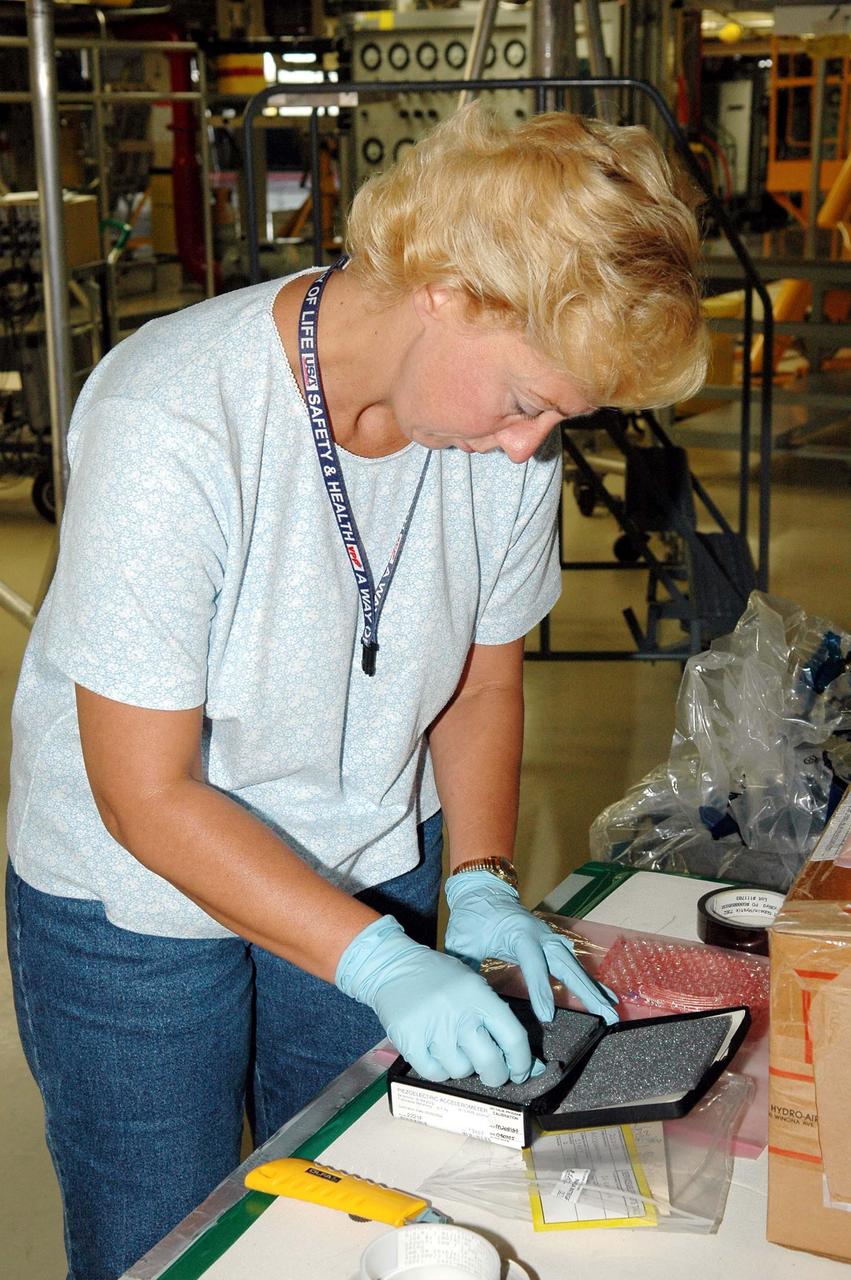
KENNEDY SPACE CENTER, FLA. - During an installation demonstration the Orbiter Processing Facility, United Space Alliance technician Lisa Campbell handles components of the sensor system being placed on the wing leading edge of orbiter Discovery. The sensors are part of the Wing Leading Edge Impact Detection System, a new safety measure added for all future Space Shuttle missions. The system also includes accelerometers that monitor the orbiter's wings for debris impacts during launch and while in orbit. There are 22 temperature sensors and 66 accelerometers on each wing. Sensor data will flow from the wing to the crew compartment, where it will be transmitted to Earth.
KENNEDY SPACE CENTER, FLA. - During an installation demonstration the Orbiter Processing Facility, United Space Alliance technician Lisa Campbell works with components of the sensor system being placed on the wing leading edge of orbiter Discovery. The sensors are part of the Wing Leading Edge Impact Detection System, a new safety measure added for all future Space Shuttle missions. The system also includes accelerometers that monitor the orbiter's wings for debris impacts during launch and while in orbit. There are 22 temperature sensors and 66 accelerometers on each wing. Sensor data will flow from the wing to the crew compartment, where it will be transmitted to Earth.
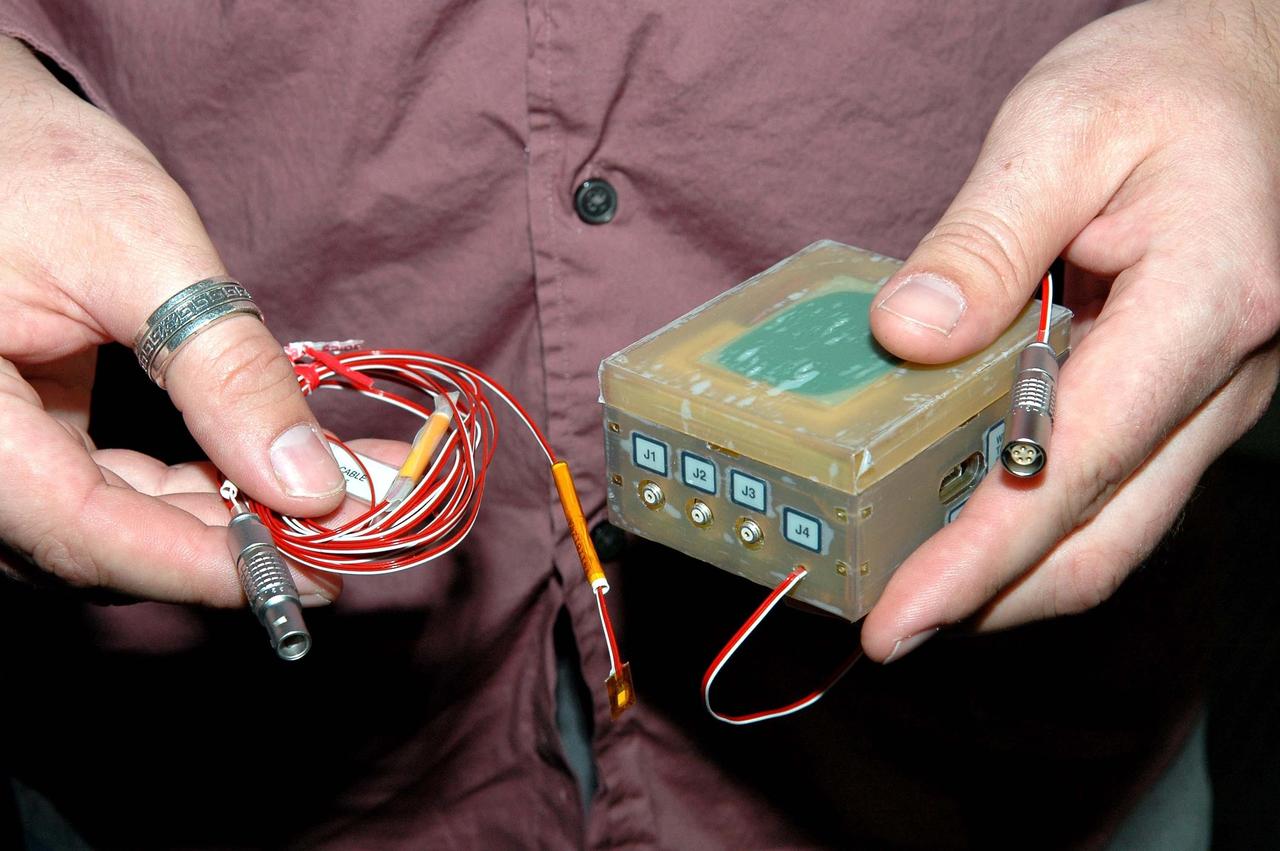
KENNEDY SPACE CENTER, FLA. - During an installation demonstration the Orbiter Processing Facility, Robert Early, lead instrument engineer with United Space Alliance, holds components of the sensor system being placed on the wing leading edge of orbiter Discovery. The sensors are part of the Wing Leading Edge Impact Detection System, a new safety measure added for all future Space Shuttle missions. The system also includes accelerometers that monitor the orbiter's wings for debris impacts during launch and while in orbit. There are 22 temperature sensors and 66 accelerometers on each wing. Sensor data will flow from the wing to the crew compartment, where it will be transmitted to Earth.
Martin Munday selects the accelerometers that will be used for vibration testing of the Orion AA-2 test article components in the Environmental Laboratory at NASA’s Armstrong Flight Research Center in California. Following Armstrong’s validation and verification work, the components will be integrated on the AA-2 test article for a flight set for 2019.
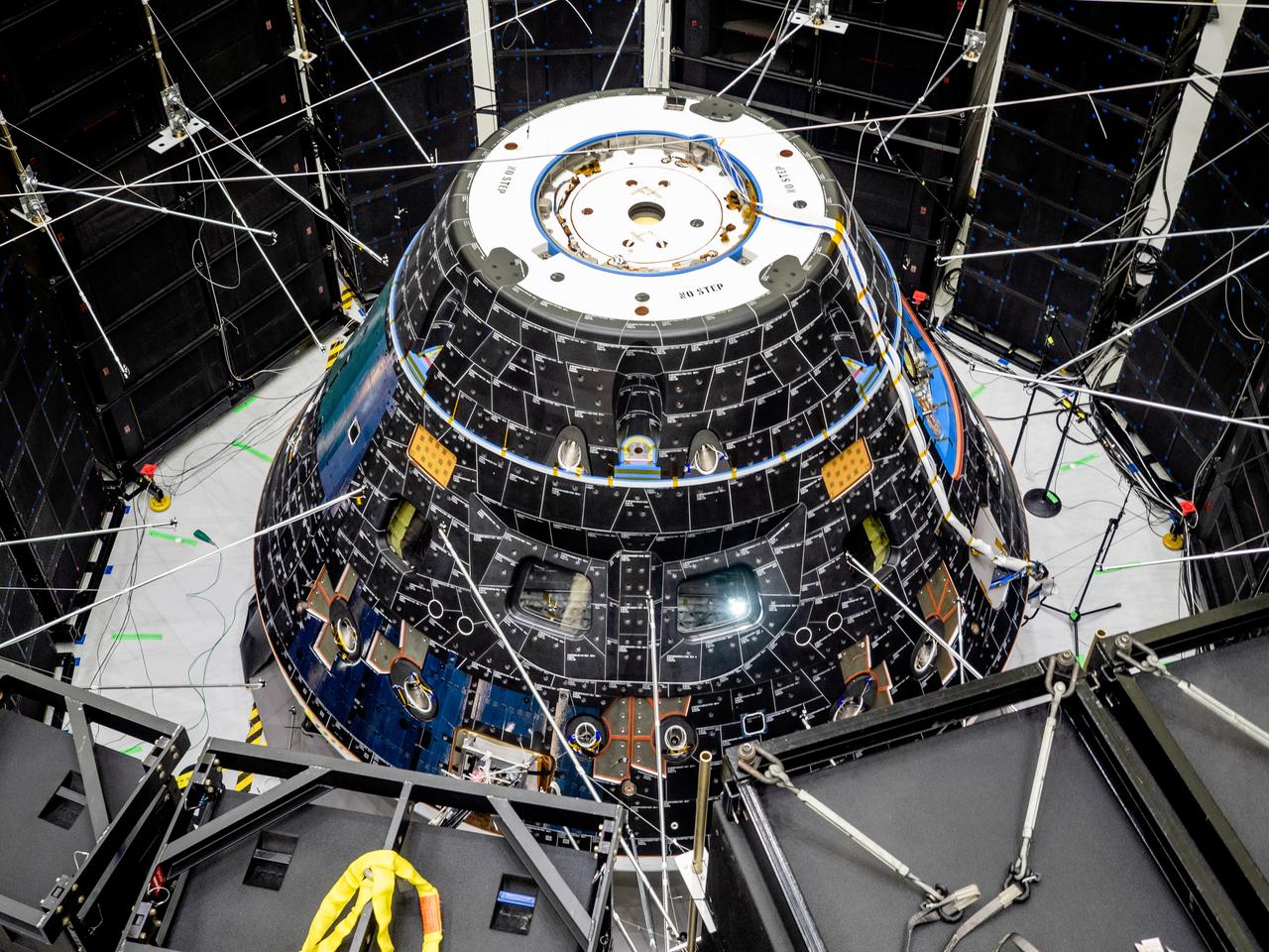
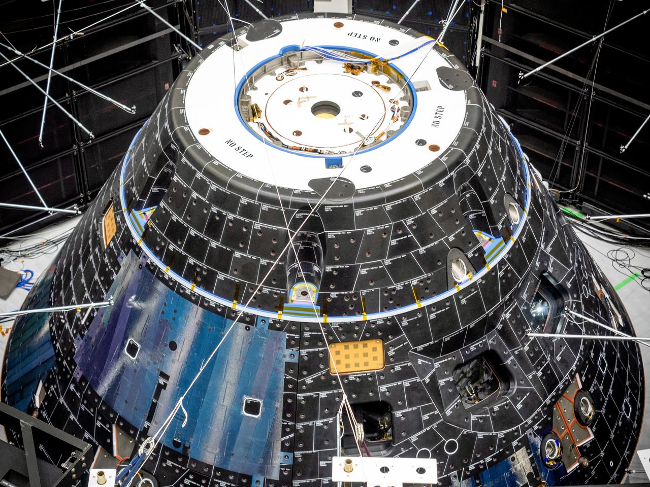
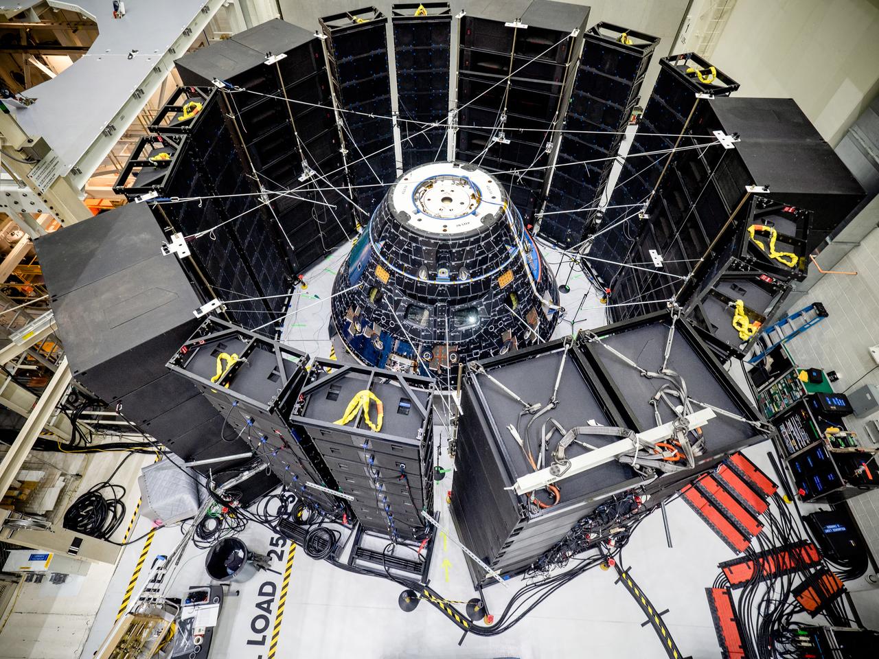
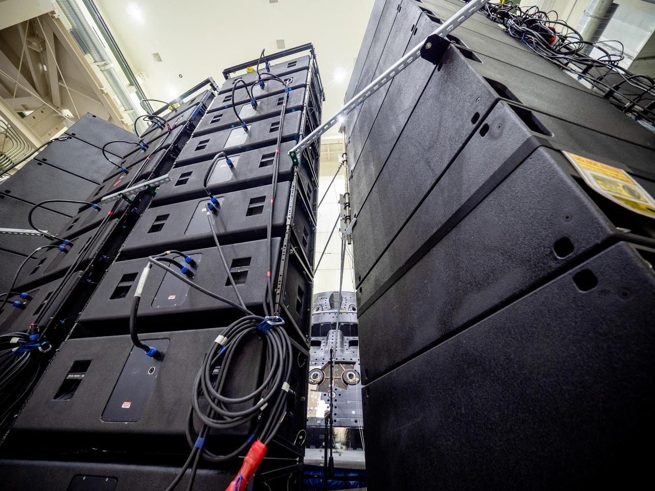
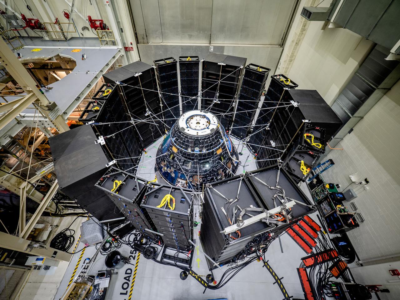
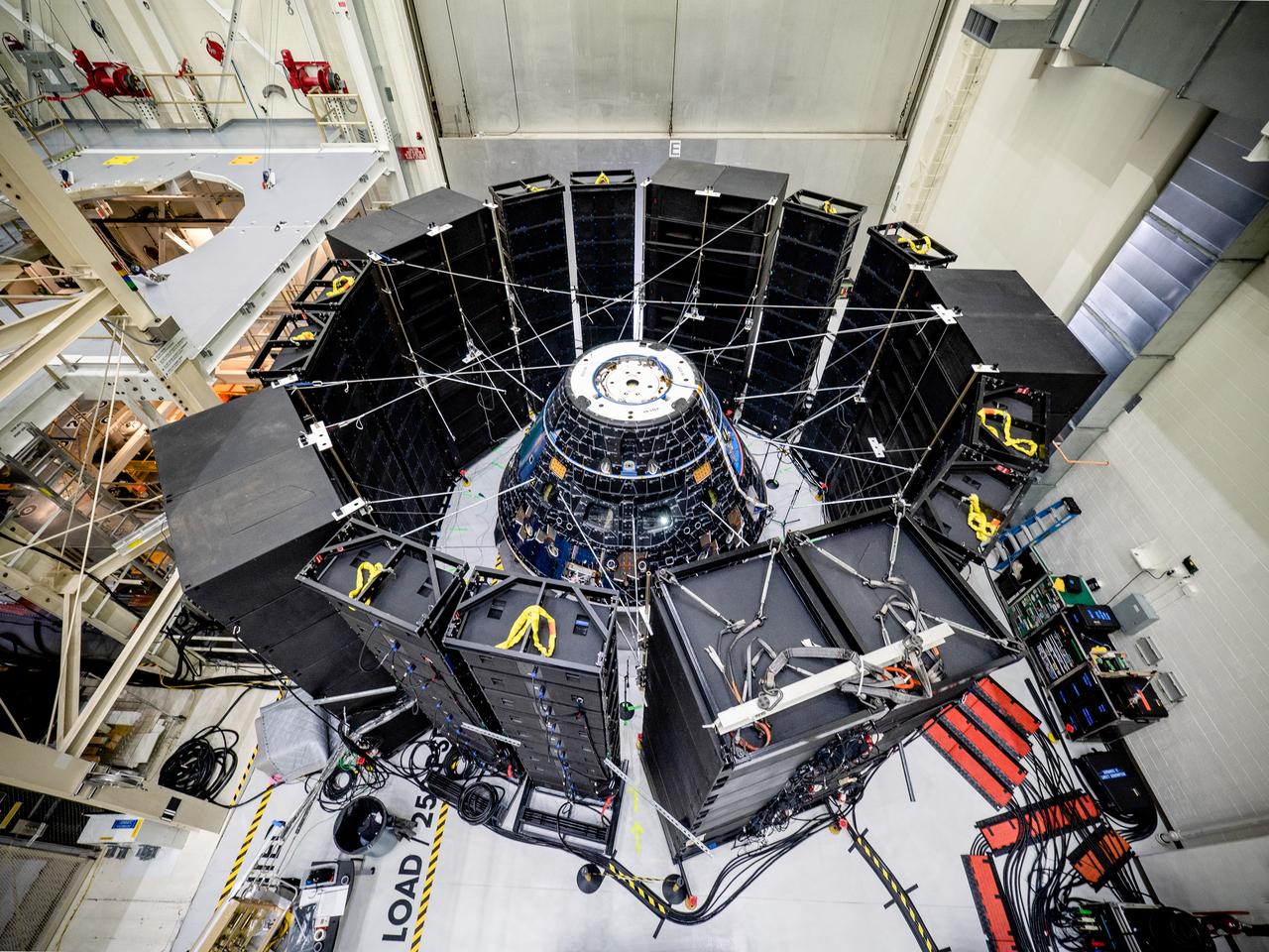
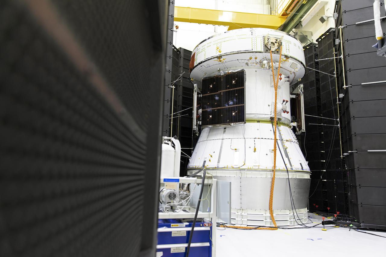
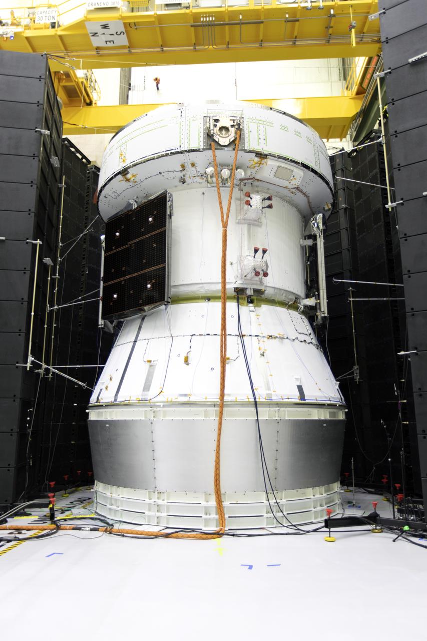
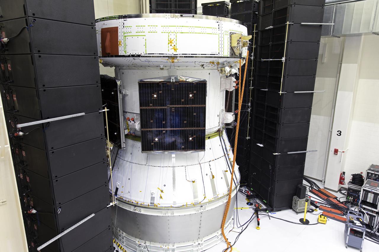
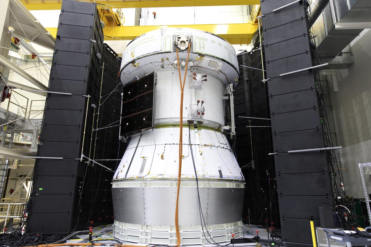
The Orion crew module for Artemis I, shown here on May 2, 2019, recently underwent Direct Field Acoustics Test (DFAT) where it was exposed to maximum acoustics levels that the vehicle will experience in space. Spacecraft response and sound pressure data were collected with microphones, strain gauges and accelerometers. The max decibel level was -12dB.
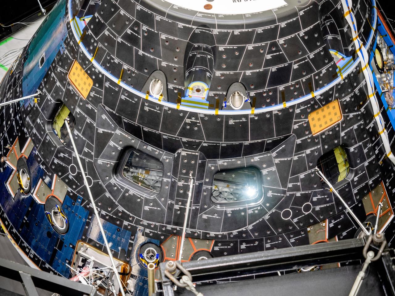
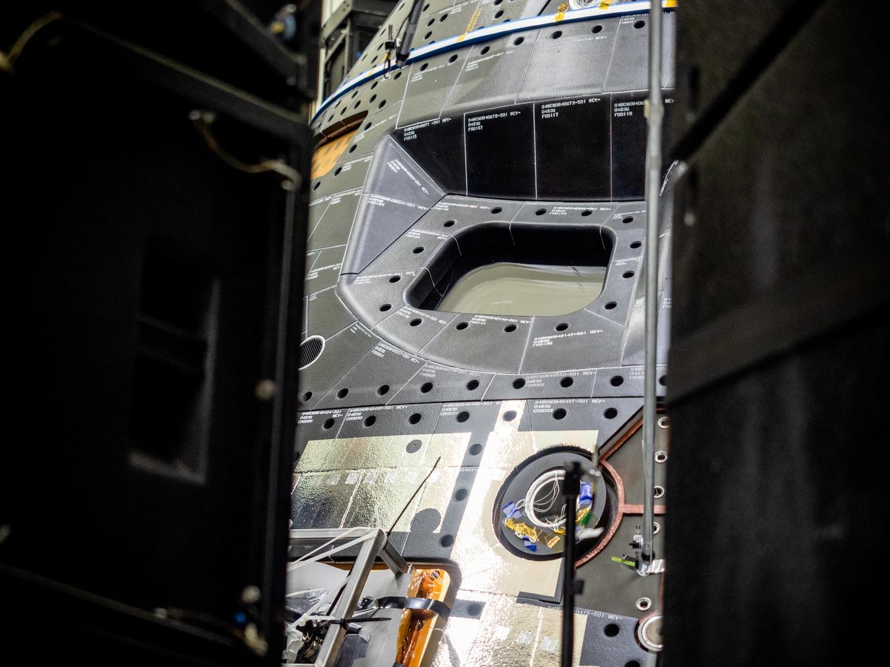
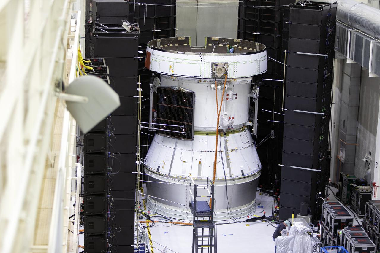
The Orion crew module for Artemis I, shown here on May 2, 2019, recently underwent Direct Field Acoustics Test (DFAT) where it was exposed to maximum acoustics levels that the vehicle will experience in space. Spacecraft response and sound pressure data were collected with microphones, strain gauges and accelerometers. The max decibel level was -12dB.
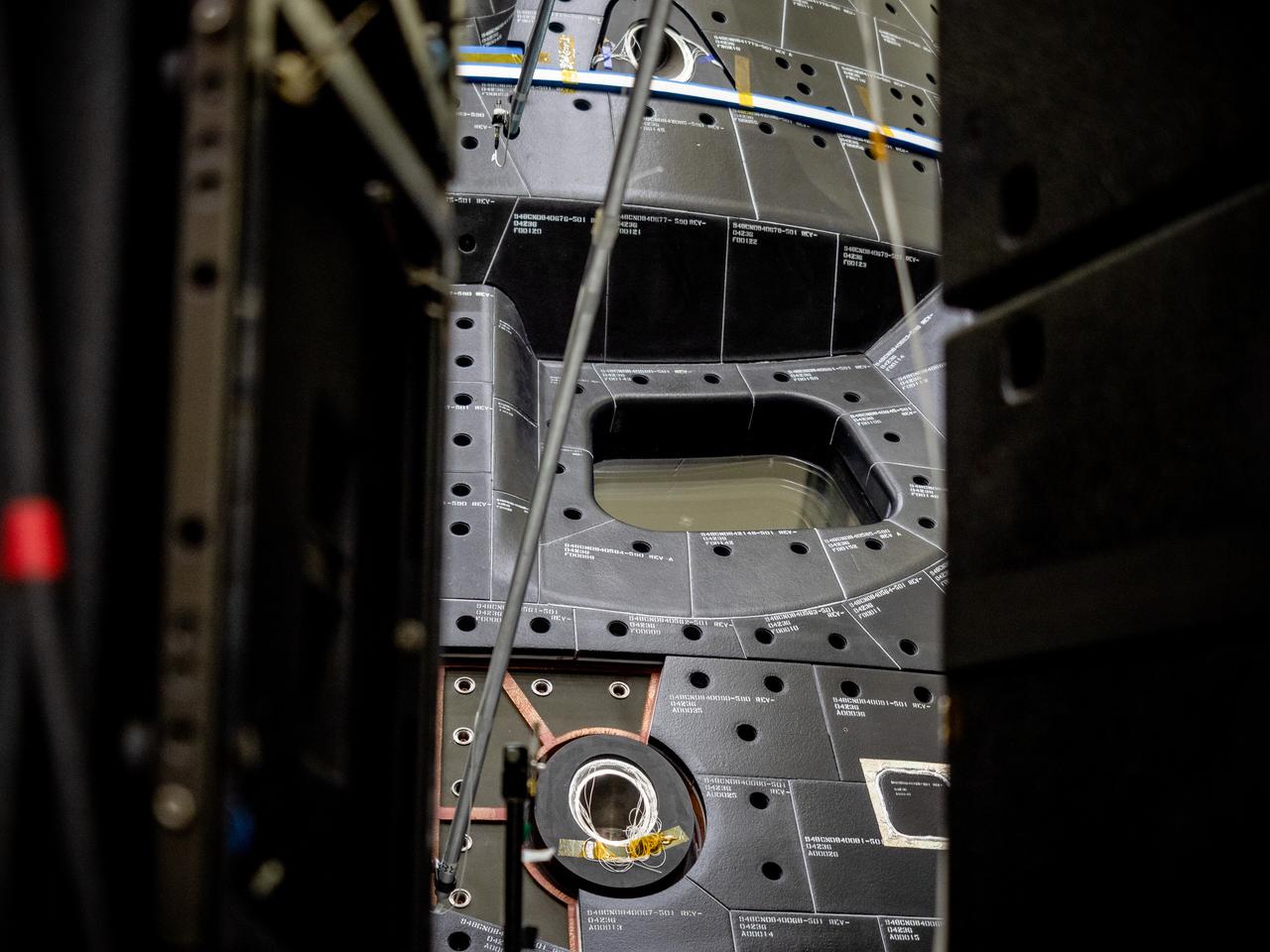
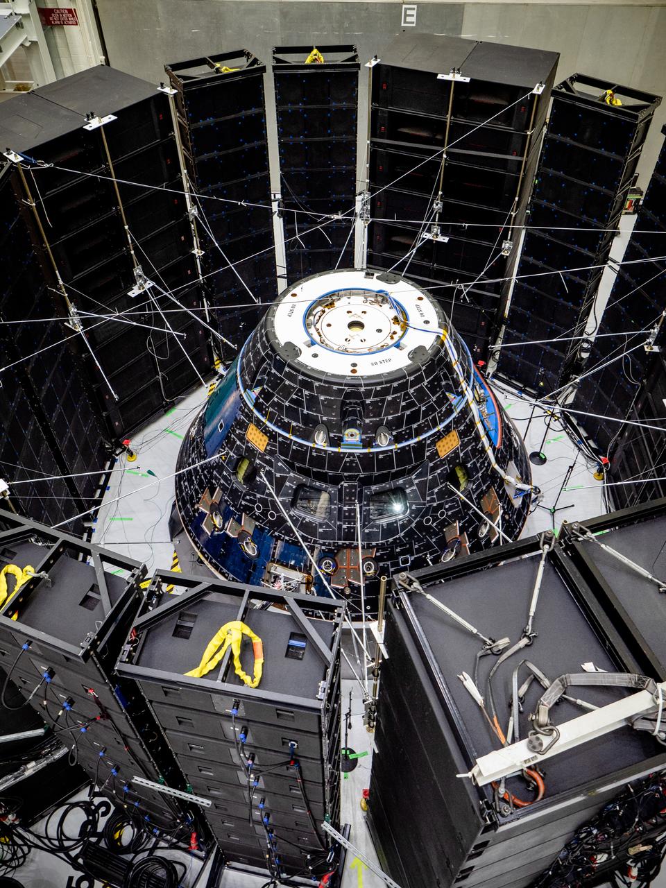
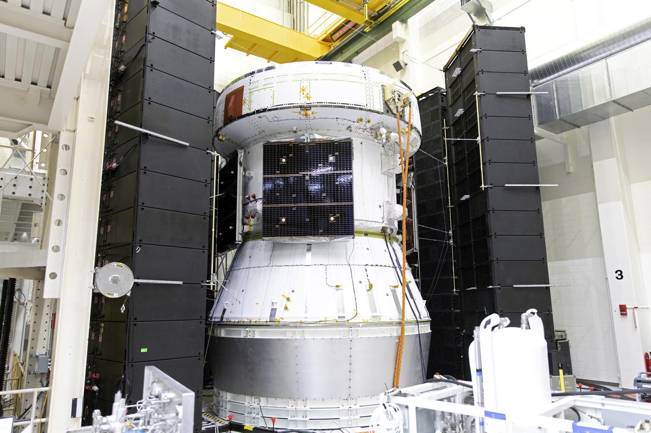
The Orion crew module for Artemis I, shown here on May 2, 2019, recently underwent Direct Field Acoustics Test (DFAT) where it was exposed to maximum acoustics levels that the vehicle will experience in space. Spacecraft response and sound pressure data were collected with microphones, strain gauges and accelerometers. The max decibel level was -12dB.
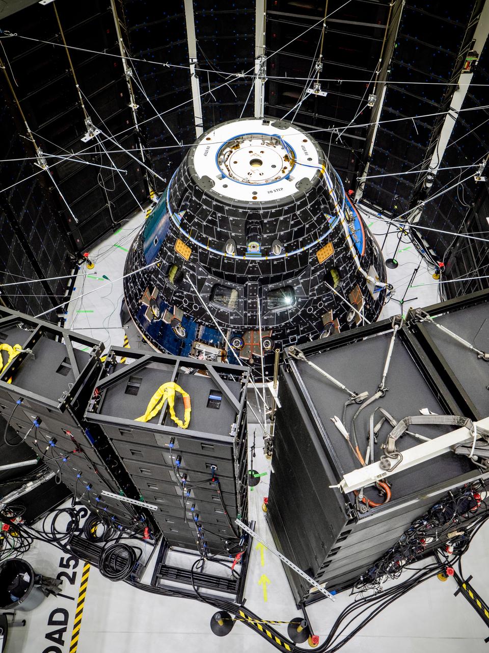
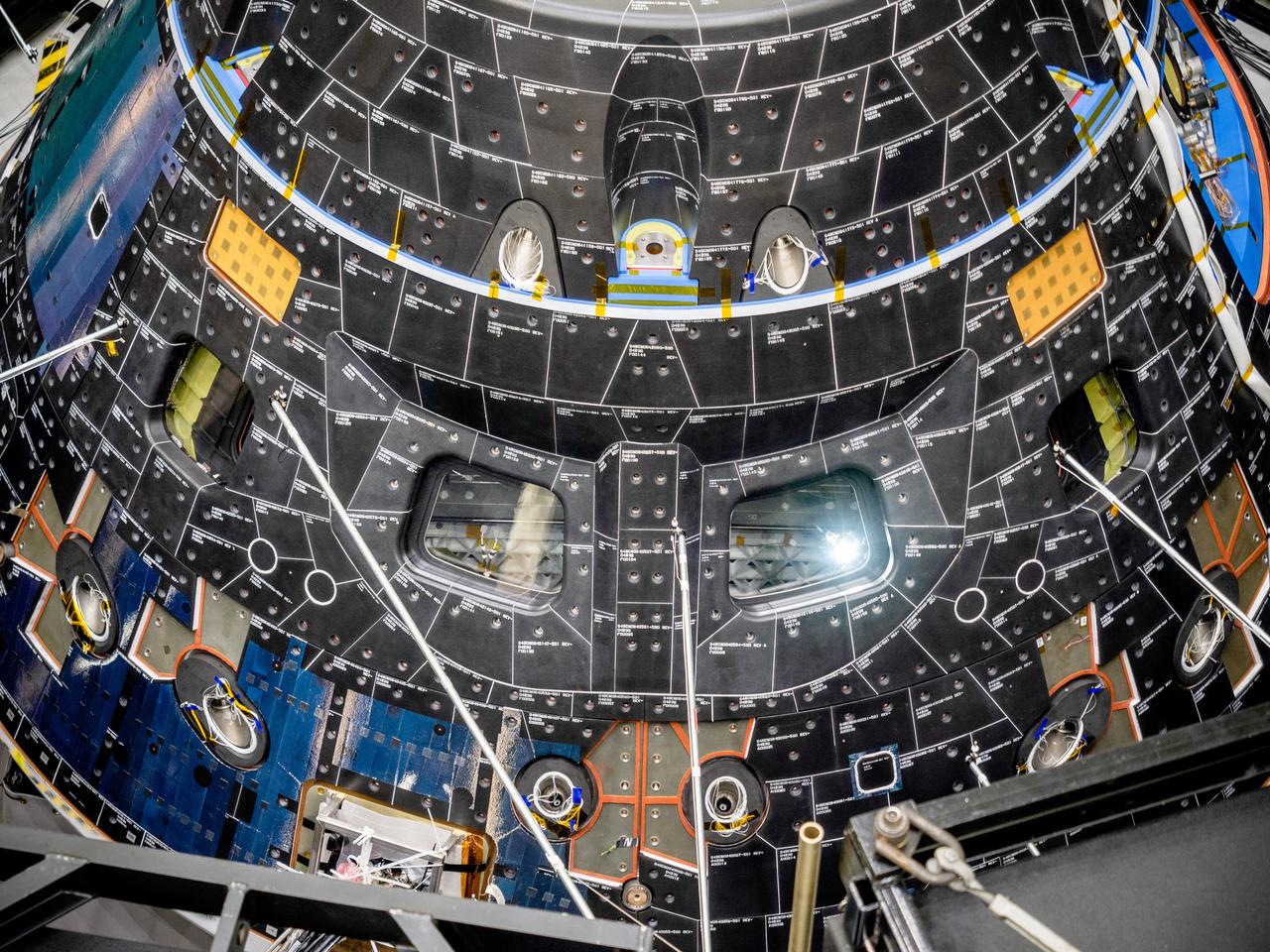
The Orion crew module for Artemis I, shown here on May 2, 2019, recently underwent Direct Field Acoustics Test (DFAT) where it was exposed to maximum acoustics levels that the vehicle will experience in space. Spacecraft response and sound pressure data were collected with microphones, strain gauges and accelerometers. The max decibel level was -12dB.
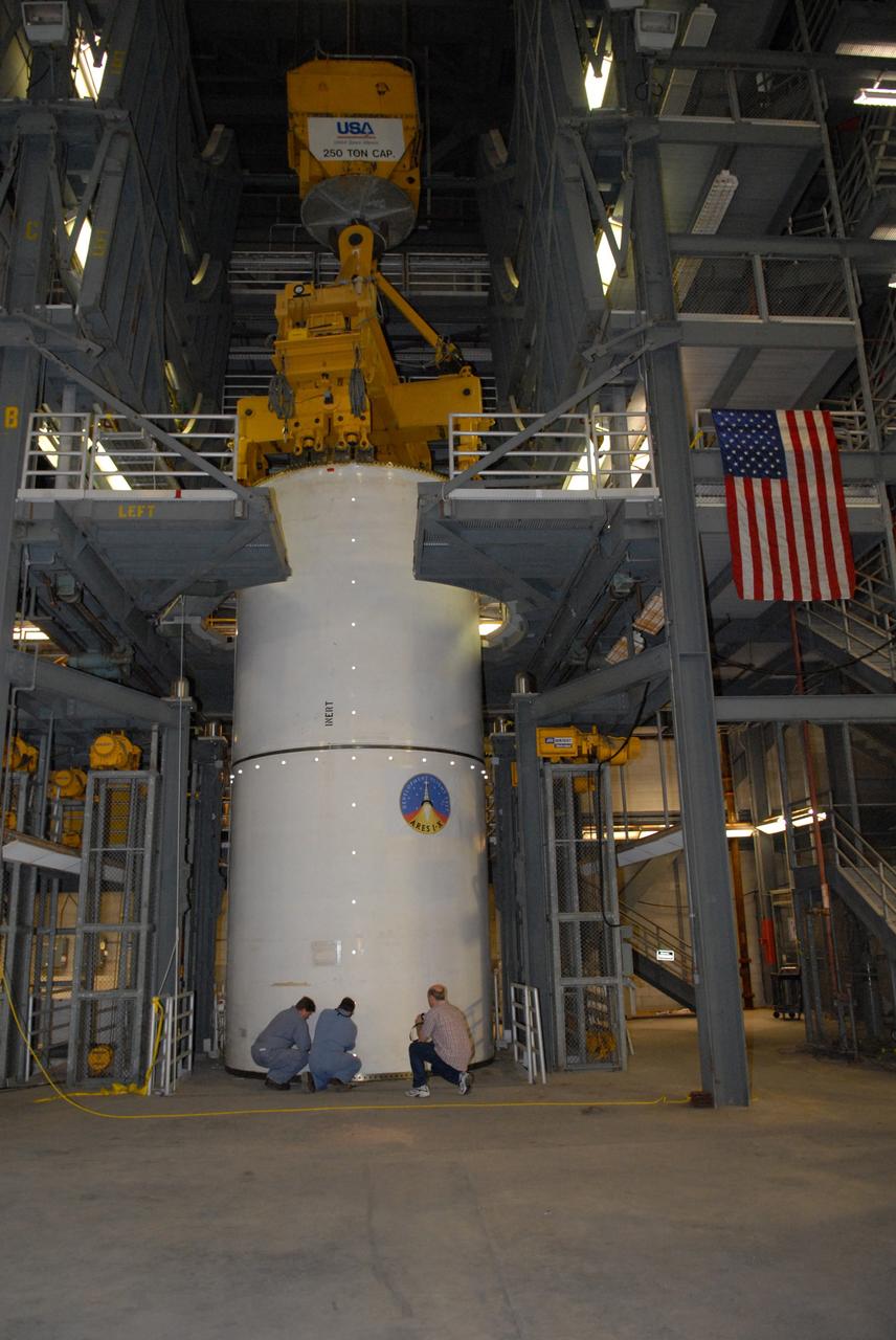
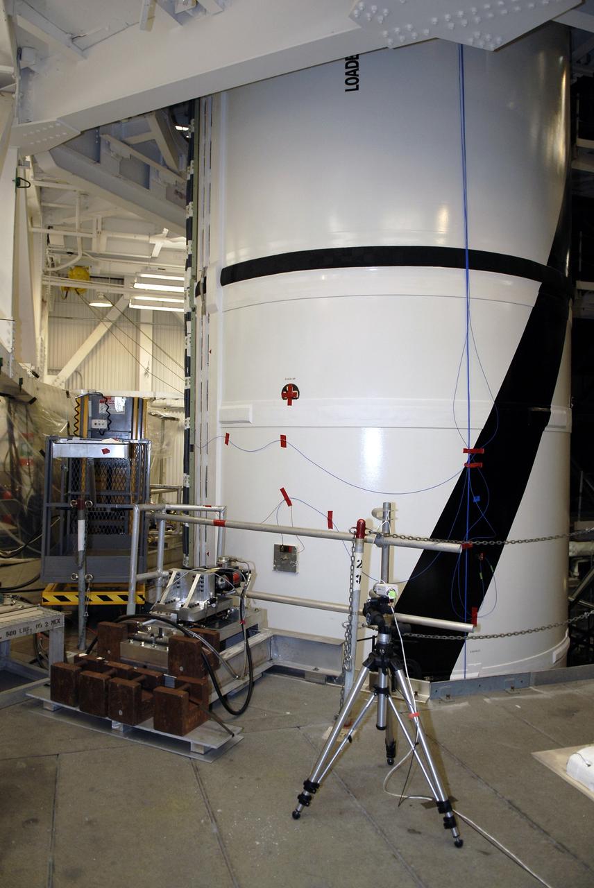
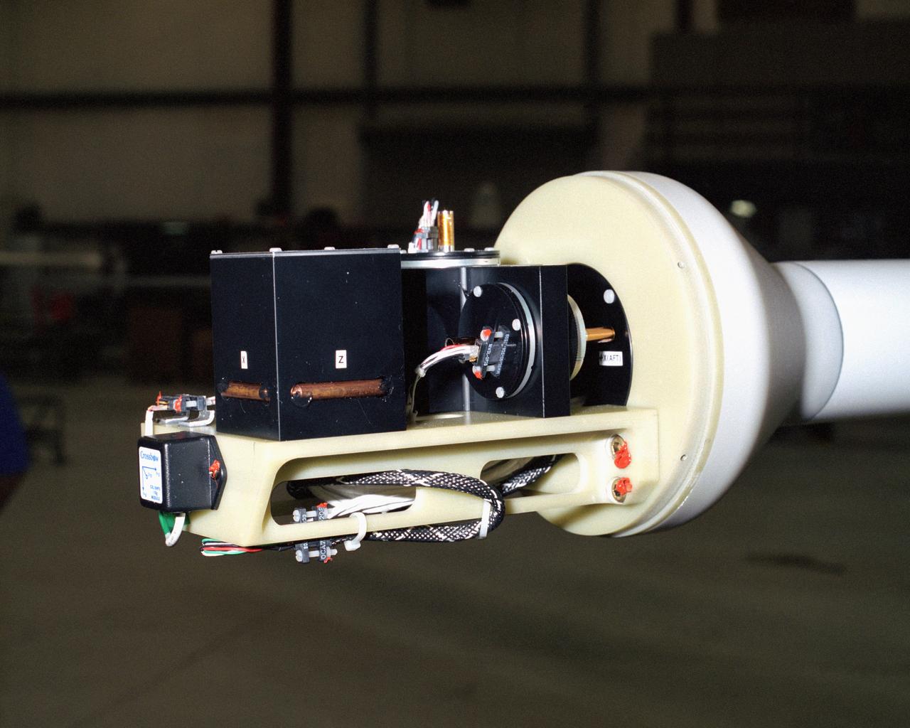
CAPE CANAVERAL, Fla. -- Vibration and laser testing is being conducted on Ares I-X segments at NASA's Kennedy Space Center. Here, technicians in the Vehicle Assembly Building configure the Inert Solid Rocket Motor Segment with an accelerometer to collect test data. Photo credit: NASA/Dimitri Gerondidakis
The Orion crew module for Artemis I, shown here on May 2, 2019, recently underwent Direct Field Acoustics Test (DFAT) where it was exposed to maximum acoustics levels that the vehicle will experience in space. Spacecraft response and sound pressure data were collected with microphones, strain gauges and accelerometers. The max decibel level was -12dB.
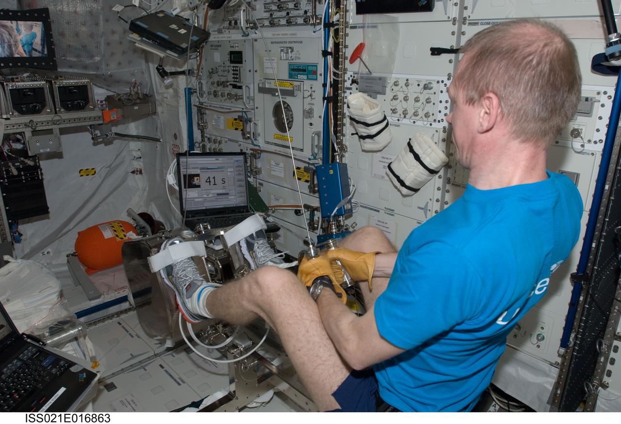
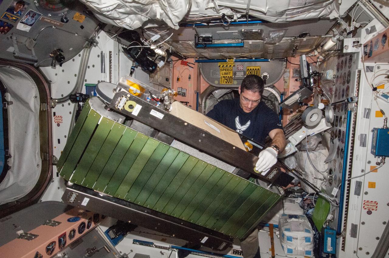
ISS038-E-046401 (12 Feb. 2014) --- NASA astronaut Mike Hopkins, Expedition 38 flight engineer, works on the COLBERT treadmill in the Unity node of the International Space Station. He replaced a failed accelerometer in the exercise device then activated COLBERT for a speed test.

The Orion crew module for Artemis I, shown here on May 2, 2019, recently underwent Direct Field Acoustics Test (DFAT) where it was exposed to maximum acoustics levels that the vehicle will experience in space. Spacecraft response and sound pressure data were collected with microphones, strain gauges and accelerometers. The max decibel level was -12dB.
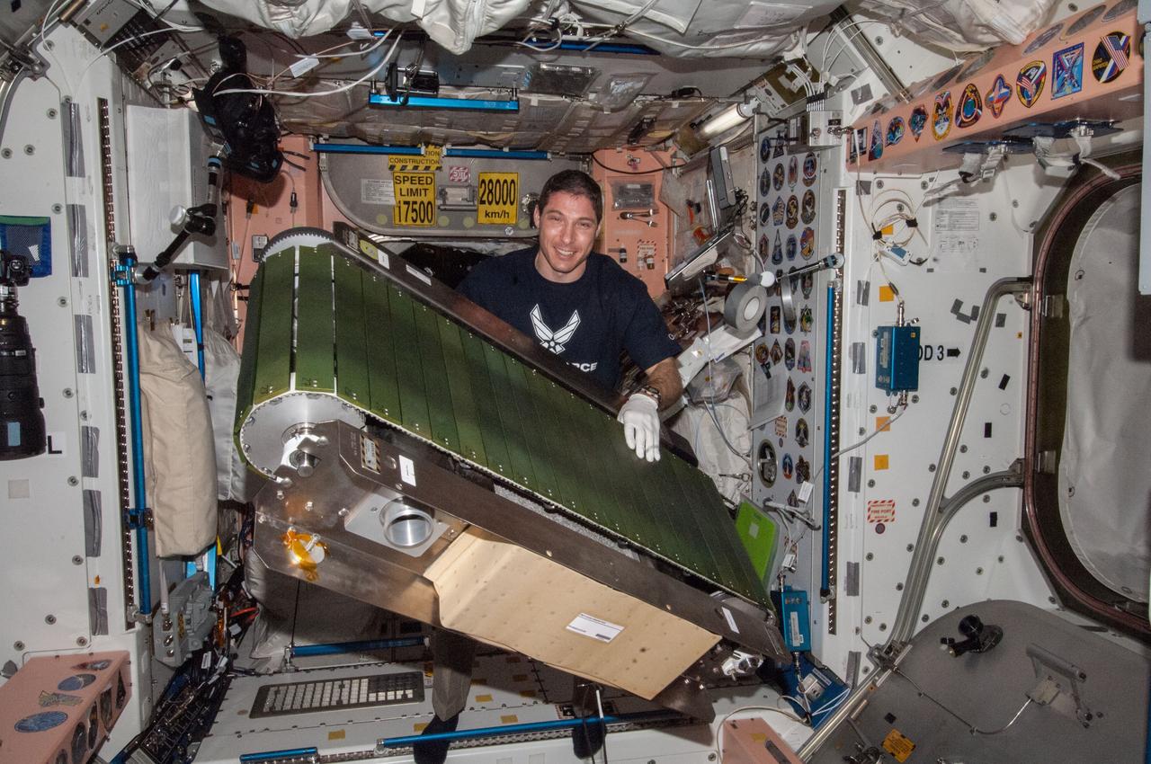
ISS021-E-016863 (28 Oct. 2009) --- European Space Agency (ESA) astronaut Frank De Winne, Expedition 21 commander, performs activation and checkout steps on the new ESA Flywheel Exercise Device (FWED), with the Internal Wireless Instrumentation System (IWIS) accelerometer, in the Columbus laboratory of the International Space Station.
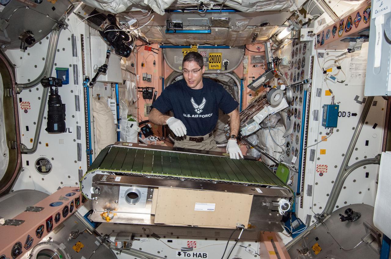
ISS038-E-046405 (12 Feb. 2014) --- NASA astronaut Mike Hopkins, Expedition 38 flight engineer, works on the COLBERT treadmill in the Unity node of the International Space Station. He replaced a failed accelerometer in the exercise device then activated COLBERT for a speed test.
The Orion crew module for Artemis I, shown here on May 2, 2019, recently underwent Direct Field Acoustics Test (DFAT) where it was exposed to maximum acoustics levels that the vehicle will experience in space. Spacecraft response and sound pressure data were collected with microphones, strain gauges and accelerometers. The max decibel level was -12dB.
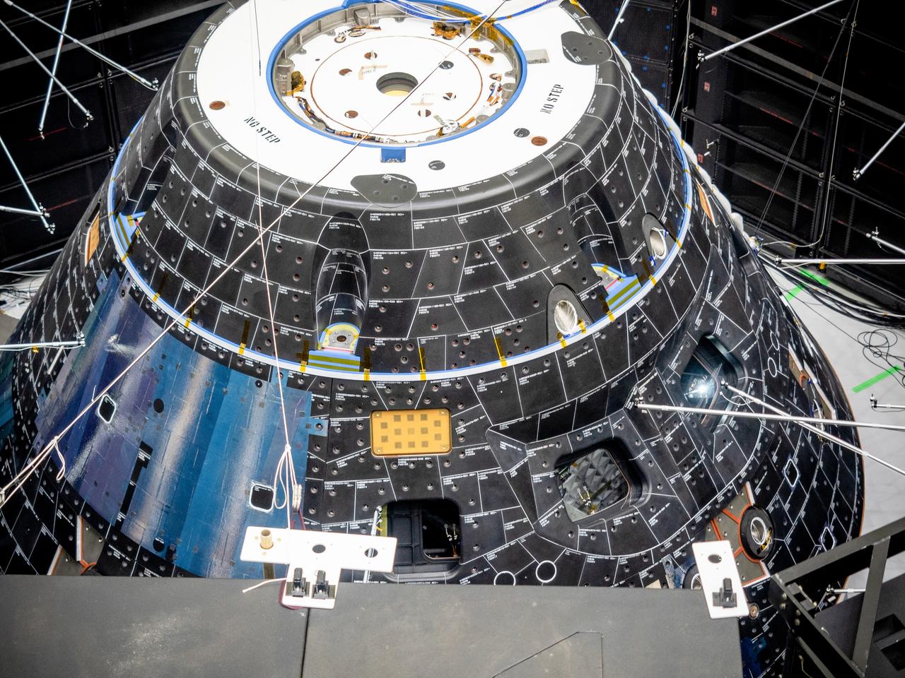
The Orion crew module for Artemis I, shown here on May 2, 2019, recently underwent Direct Field Acoustics Test (DFAT) where it was exposed to maximum acoustics levels that the vehicle will experience in space. Spacecraft response and sound pressure data were collected with microphones, strain gauges and accelerometers. The max decibel level was -12dB.

The Orion crew module for Artemis I, shown here on May 2, 2019, recently underwent Direct Field Acoustics Test (DFAT) where it was exposed to maximum acoustics levels that the vehicle will experience in space. Spacecraft response and sound pressure data were collected with microphones, strain gauges and accelerometers. The max decibel level was -12dB.
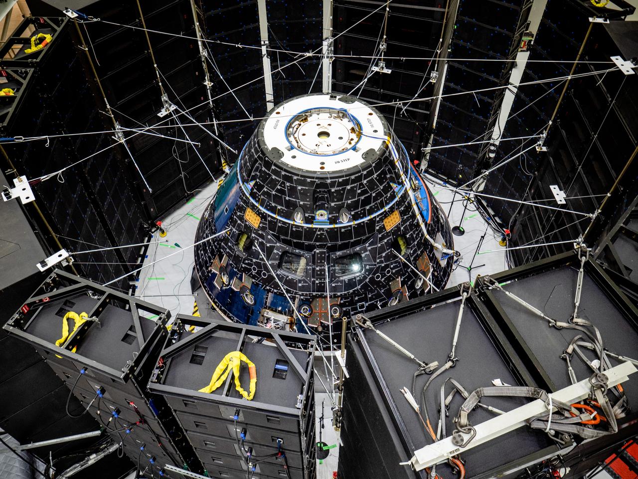
The Orion crew module for Artemis I, shown here on May 2, 2019, recently underwent Direct Field Acoustics Test (DFAT) where it was exposed to maximum acoustics levels that the vehicle will experience in space. Spacecraft response and sound pressure data were collected with microphones, strain gauges and accelerometers. The max decibel level was -12dB.
The Orion crew module for Artemis I, shown here on May 2, 2019, recently underwent Direct Field Acoustics Test (DFAT) where it was exposed to maximum acoustics levels that the vehicle will experience in space. Spacecraft response and sound pressure data were collected with microphones, strain gauges and accelerometers. The max decibel level was -12dB.

The Orion crew module for Artemis I, shown here on May 2, 2019, recently underwent Direct Field Acoustics Test (DFAT) where it was exposed to maximum acoustics levels that the vehicle will experience in space. Spacecraft response and sound pressure data were collected with microphones, strain gauges and accelerometers. The max decibel level was -12dB.
ISS038-E-046404 (12 Feb. 2014) --- NASA astronaut Mike Hopkins, Expedition 38 flight engineer, works on the COLBERT treadmill in the Unity node of the International Space Station. He replaced a failed accelerometer in the exercise device then activated COLBERT for a speed test.
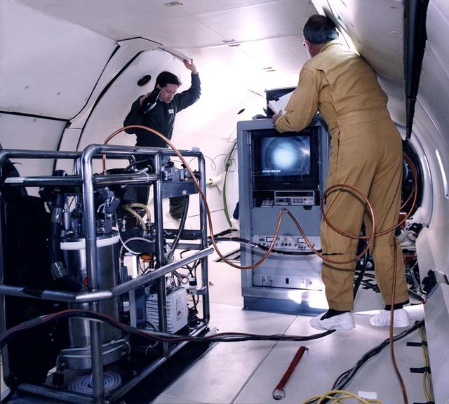
Ted Brunzie and Peter Mason observe the float package and the data rack aboard the DC-9 reduced gravity aircraft. The float package contains a cryostat, a video camera, a pump and accelerometers. The data rack displays and record the video signal from the float package on tape and stores acceleration and temperature measurements on disk.
The Orion crew module for Artemis I, shown here on May 2, 2019, recently underwent Direct Field Acoustics Test (DFAT) where it was exposed to maximum acoustics levels that the vehicle will experience in space. Spacecraft response and sound pressure data were collected with microphones, strain gauges and accelerometers. The max decibel level was -12dB.
The Orion crew module for Artemis I, shown here on May 2, 2019, recently underwent Direct Field Acoustics Test (DFAT) where it was exposed to maximum acoustics levels that the vehicle will experience in space. Spacecraft response and sound pressure data were collected with microphones, strain gauges and accelerometers. The max decibel level was -12dB.
The Orion crew module for Artemis I, shown here on May 2, 2019, recently underwent Direct Field Acoustics Test (DFAT) where it was exposed to maximum acoustics levels that the vehicle will experience in space. Spacecraft response and sound pressure data were collected with microphones, strain gauges and accelerometers. The max decibel level was -12dB.
The Orion crew module for Artemis I, shown here on May 2, 2019, recently underwent Direct Field Acoustics Test (DFAT) where it was exposed to maximum acoustics levels that the vehicle will experience in space. Spacecraft response and sound pressure data were collected with microphones, strain gauges and accelerometers. The max decibel level was -12dB.
The Orion crew module for Artemis I, shown here on May 2, 2019, recently underwent Direct Field Acoustics Test (DFAT) where it was exposed to maximum acoustics levels that the vehicle will experience in space. Spacecraft response and sound pressure data were collected with microphones, strain gauges and accelerometers. The max decibel level was -12dB.
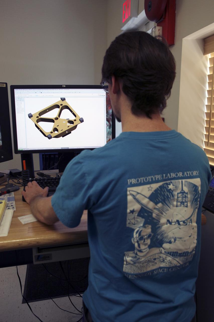
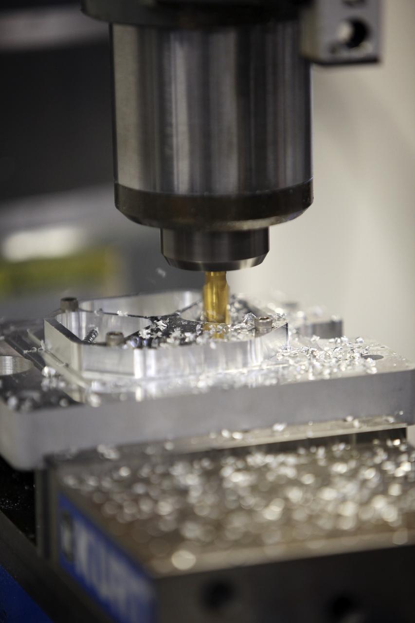
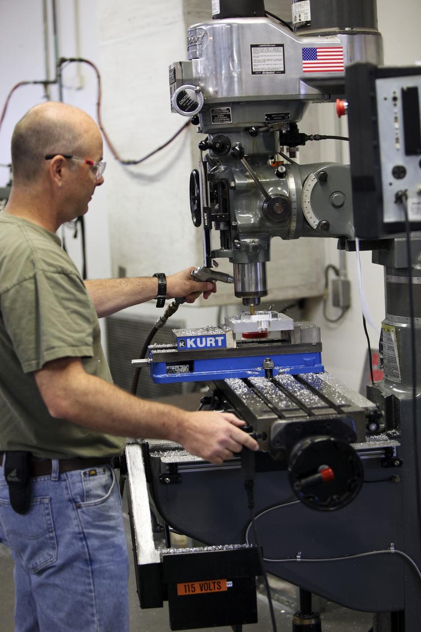
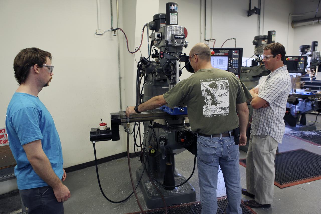
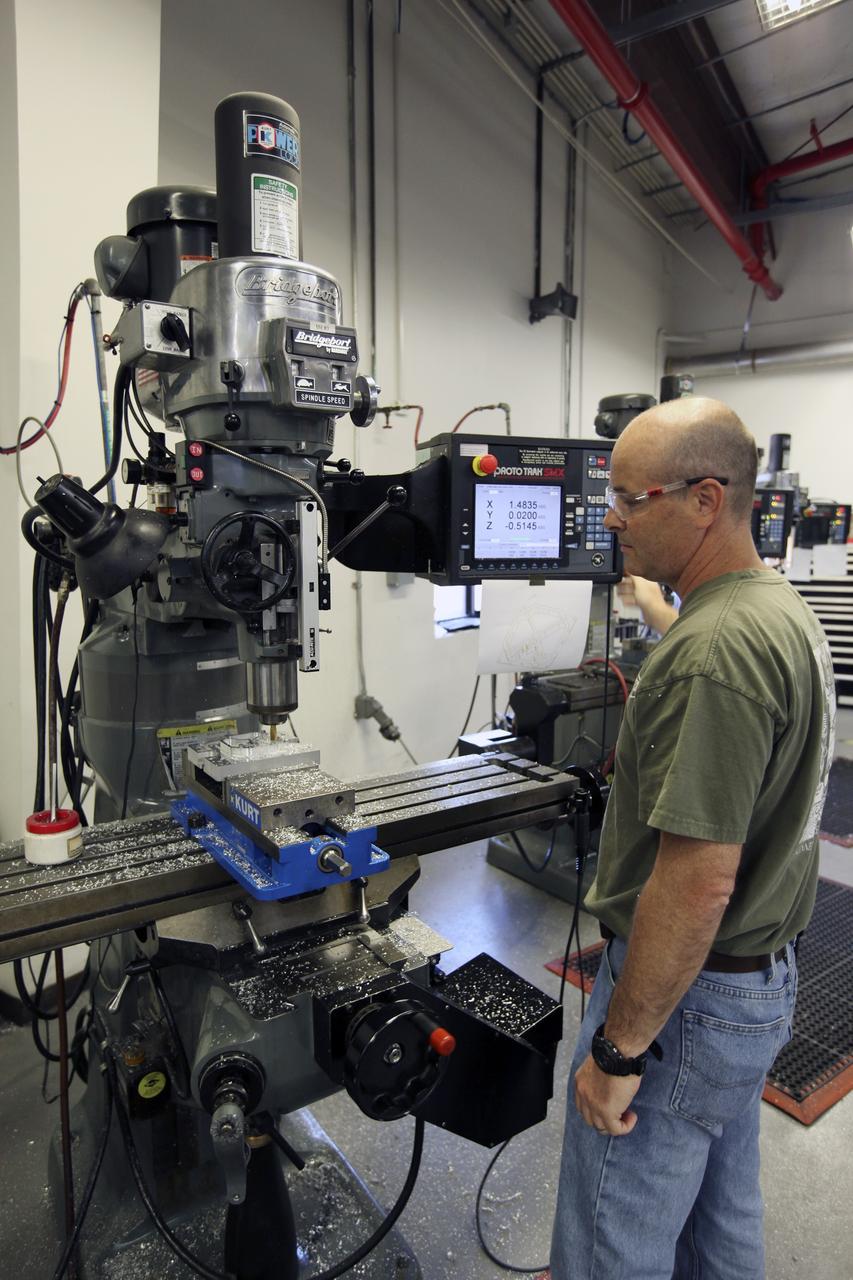
CAPE CANAVERAL, Fla. – A component is machined for a cubesat that is being assembled for launch in June. The component, being machined at NASA's Kennedy Space Center in Florida will hold accelerometers for the StangSat, which is a project whose development includes students from Merritt Island High School in Florida. The satellite will work inside a small rocket to measure vibration and collect other data during launch. NASA engineers are acting as mentors for the project. Photo credit: NASA/Dmitri Gerondidakis
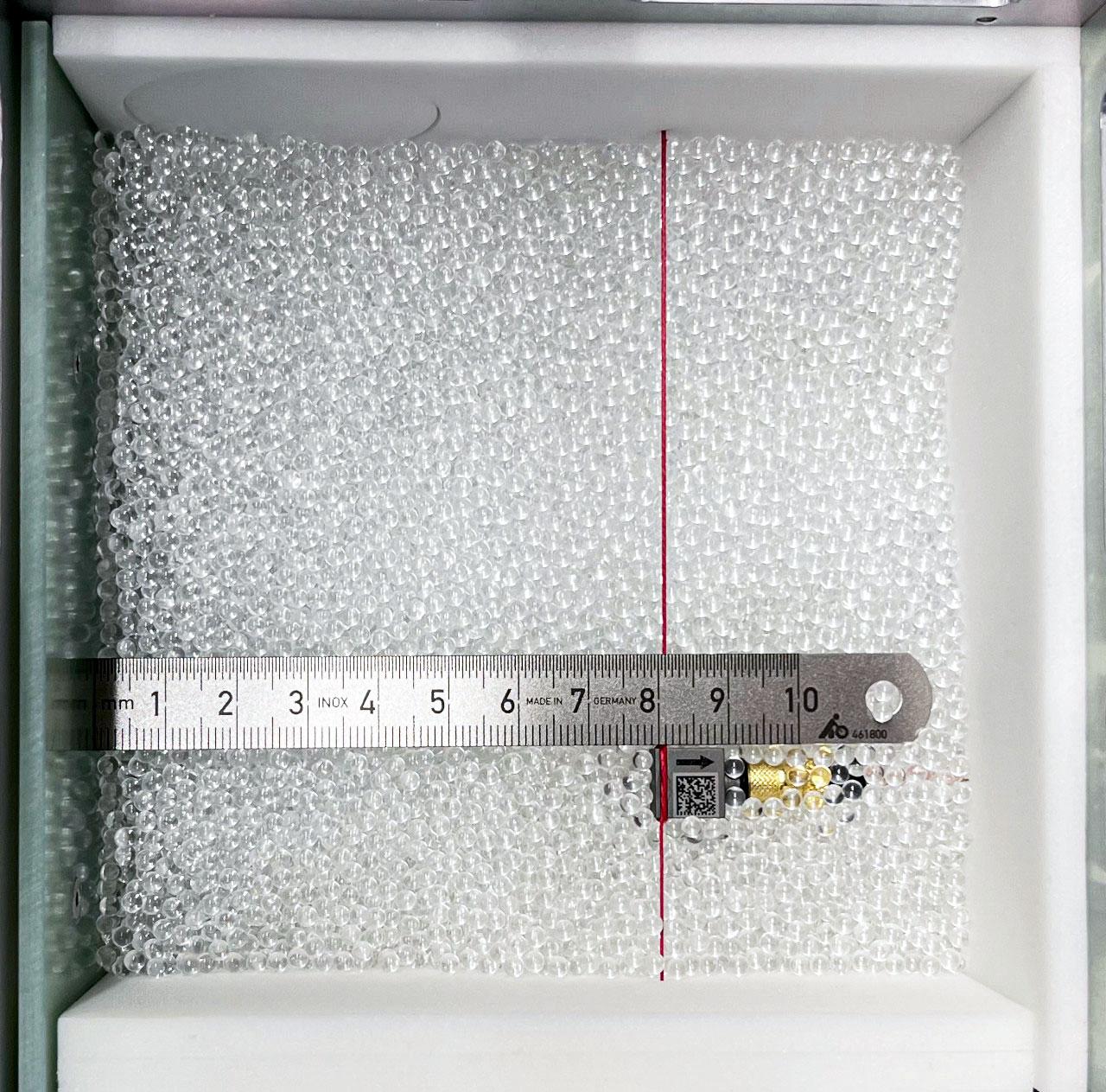
jsc2023e053546 (3/3/2023) --- Granular Sound: open sample cell, partially filled with glass beads, with one accelerometer exposed whose position from the voicecoil-driven wall on the left is indicated by a metal ruler. Also visible: the sample cell walls are padded with foam for acoustic decoupling of the glass bead packing. Image courtesy of DLR-MP.
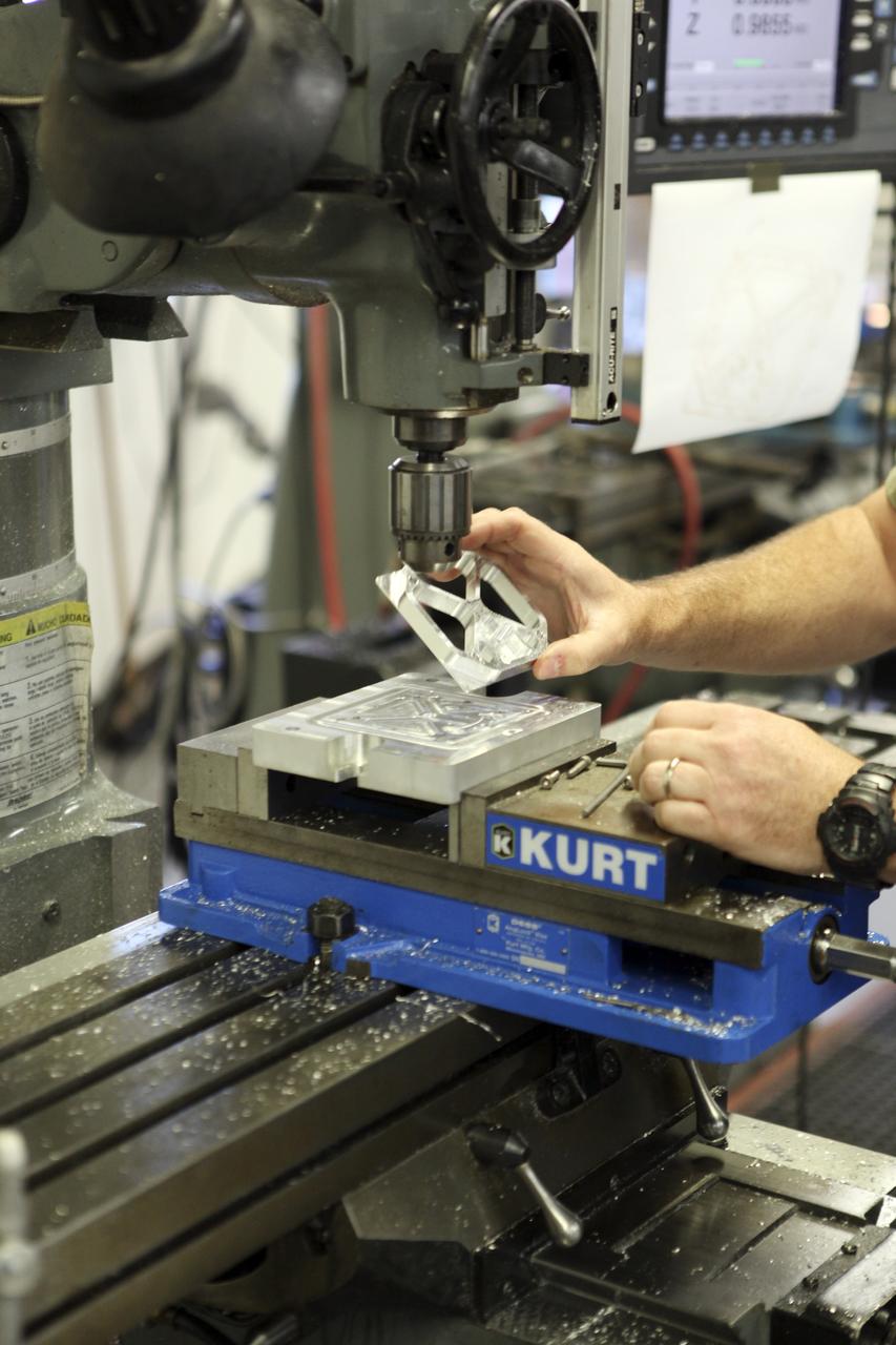
CAPE CANAVERAL, Fla. – A component is machined for a cubesat that is being assembled for launch in June. The component, being machined at NASA's Kennedy Space Center in Florida will hold accelerometers for the StangSat, which is a project whose development includes students from Merritt Island High School in Florida. The satellite will work inside a small rocket to measure vibration and collect other data during launch. NASA engineers are acting as mentors for the project. Photo credit: NASA/Dmitri Gerondidakis
CAPE CANAVERAL, Fla. – A component is machined for a cubesat that is being assembled for launch in June. The component, being machined at NASA's Kennedy Space Center in Florida will hold accelerometers for the StangSat, which is a project whose development includes students from Merritt Island High School in Florida. The satellite will work inside a small rocket to measure vibration and collect other data during launch. NASA engineers are acting as mentors for the project. Photo credit: NASA/Dmitri Gerondidakis
CAPE CANAVERAL, Fla. – A component is machined for a cubesat that is being assembled for launch in June. The component, being machined at NASA's Kennedy Space Center in Florida will hold accelerometers for the StangSat, which is a project whose development includes students from Merritt Island High School in Florida. The satellite will work inside a small rocket to measure vibration and collect other data during launch. NASA engineers are acting as mentors for the project. Photo credit: NASA/Dmitri Gerondidakis
CAPE CANAVERAL, Fla. – A component is machined for a cubesat that is being assembled for launch in June. The component, being machined at NASA's Kennedy Space Center in Florida will hold accelerometers for the StangSat, which is a project whose development includes students from Merritt Island High School in Florida. The satellite will work inside a small rocket to measure vibration and collect other data during launch. NASA engineers are acting as mentors for the project. Photo credit: NASA/Dmitri Gerondidakis
STS048-10-023 (16 Sept 1991) --- Astronaut James F. Buchli poses with the structural test article (STA), a model of the space station truss structure. The STA is part of the middeck zero gravity dynamics experiment (MODE). MODE was designed to study the vibration characteristics of the jointed truss structure. The structural test article includes four strain gauges and eleven accelerometers and is vibrated by an actuator. Assembled by crewmembers in the Shuttle orbiter's middeck, the device is about 72 inches long with an 8-inch square cross section.
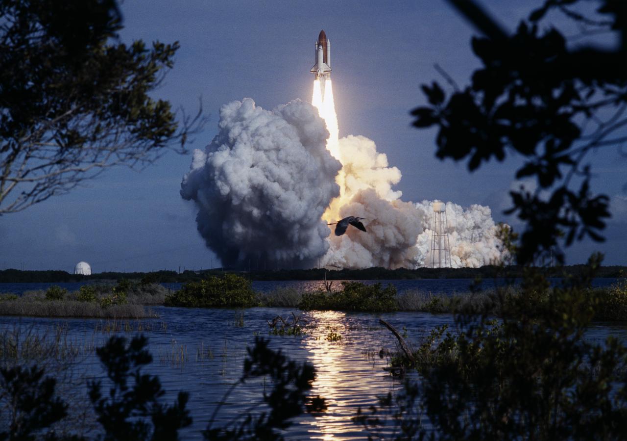
A Great Blue Heron seems oblivious to the tremendous spectacle of light and sound generated by a Shuttle liftoff, as the Space Shuttle Columbia (STS-73) soars skyward from Launch Pad 39B. Columbia's seven member crew's mission included continuing experimentation in the Marshall managed payloads including the United States Microgravity Laboratory 2 (USML-2) and the keel-mounted accelerometer that characterizes the very low frequency acceleration environment of the orbiter payload bay during space flight, known as the Orbital Acceleration Research Experiment (OARE).
CAPE CANAVERAL, Fla. – A component is machined for a cubesat that is being assembled for launch in June. The component, being machined at NASA's Kennedy Space Center in Florida will hold accelerometers for the StangSat, which is a project whose development includes students from Merritt Island High School in Florida. The satellite will work inside a small rocket to measure vibration and collect other data during launch. NASA engineers are acting as mentors for the project. Photo credit: NASA/Dmitri Gerondidakis
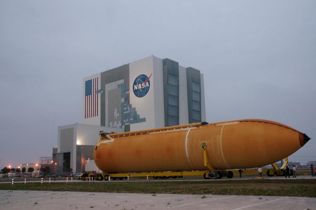
KENNEDY SPACE CENTER, FLA. -The second redesigned External Tank (ET-121) moves slowly on the road from the Turn Basin to the Vehicle Assembly Building in the background. The tank recently arrived at the Turn Basin aboard a barge after its 900-mile journey at sea from the Michoud Assembly Facility in New Orleans. In addition to the Return to Flight modifications, this tank has been outfitted with temperature sensors and accelerometers, used to measure vibration. These sensors will gather information about how the tank performs during flight. The tank is designated for use on Return to Flight mission STS-121, which has a launch window of July 12 to July 31, 2005.
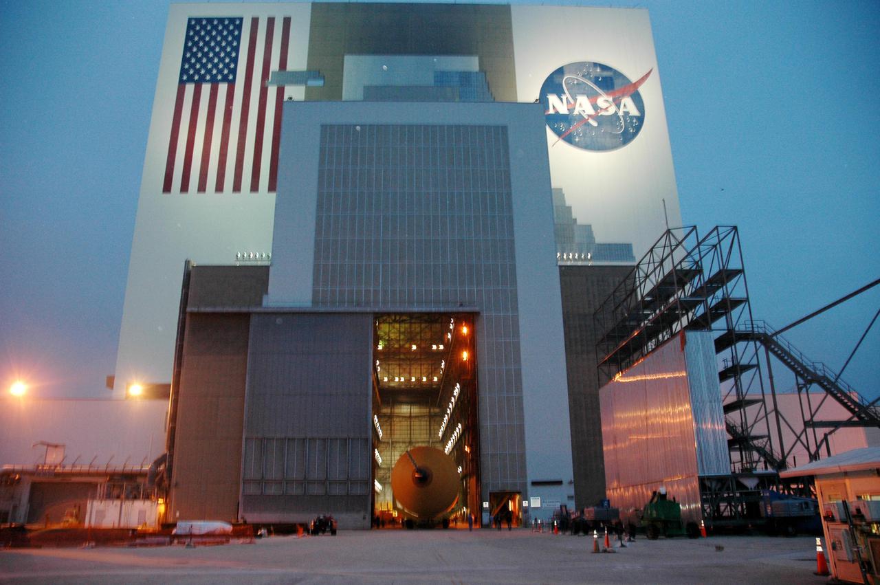
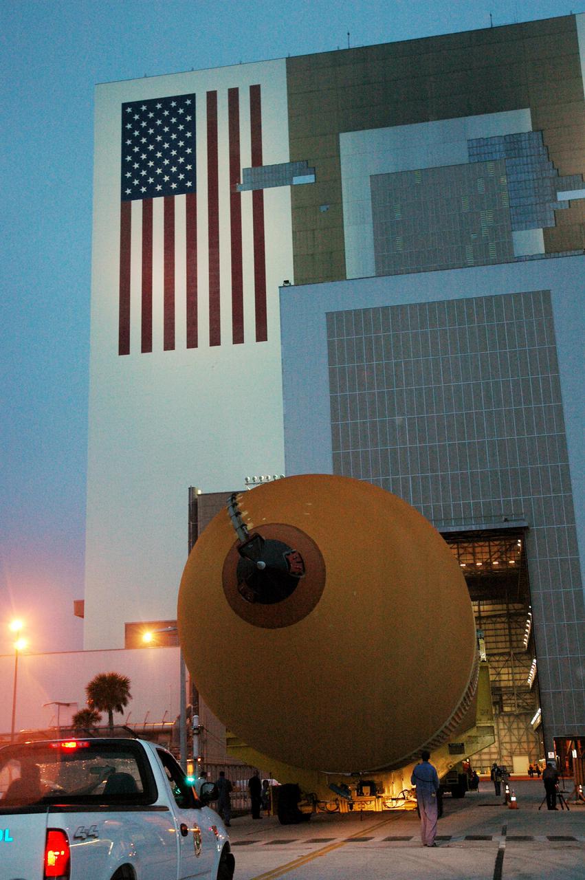
KENNEDY SPACE CENTER, FLA. - Through the open doors of the Vehicle Assembly Building can be seen the second redesigned External Tank (ET-121). The tank recently arrived at the Turn Basin after its 900-mile journey at sea from the Michoud Assembly Facility in New Orleans. In addition to the Return to Flight modifications, this tank has been outfitted with temperature sensors and accelerometers, used to measure vibration. These sensors will gather information about how the tank performs during flight. The tank is designated for use on Return to Flight mission STS-121, which has a launch window of July 12 to July 31, 2005.
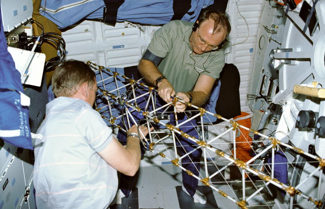
STS048-09-019 (16 Sept 1991) --- Astronauts Mark N. Brown, left, and James F. Buchli work with the structural test article (STA), a model of the space station truss structure. STA is part of the middeck zero gravity dynamics experiment (MODE). MODE was designed to study the vibration characteristics of the jointed truss structure. The structural test article includes four strain gauges and eleven accelerometers and is vibrated by an actuator. Assembled by crewmembers in the Shuttle orbiter's middeck, the device is about 72 inches long with an 8-inch square cross section.
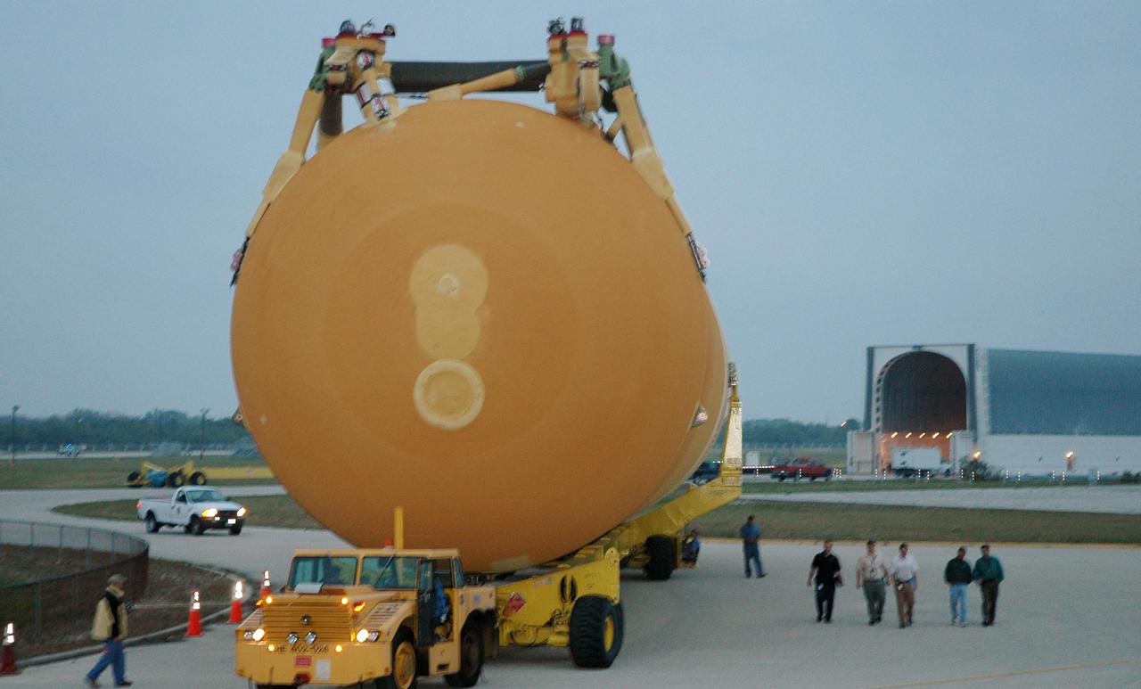
KENNEDY SPACE CENTER, FLA. - The second redesigned External Tank (ET-121) dwarfs the workers accompanying it on its way to the Vehicle Assembly Building. The tank recently arrived at the Turn Basin aboard the barge in the background after its 900-mile journey at sea from the Michoud Assembly Facility in New Orleans. In addition to the Return to Flight modifications, this tank has been outfitted with temperature sensors and accelerometers, used to measure vibration. These sensors will gather information about how the tank performs during flight. The tank is designated for use on Return to Flight mission STS-121, which has a launch window of July 12 to July 31, 2005.

Side-by-side images depict NASA's Curiosity rover (left) and a moon buggy driven during the Apollo 16 mission. Moon buggies were used during the Apollo missions to carry astronauts, lunar samples and equipment. During the Apollo 17 mission, that equipment included the Traverse Gravimeter Experiment (TGE), a special instrument for measuring gravity. Curiosity wasn't sent to Mars with gravimeters, but it does have accelerometers that are used to navigate the rover. A paper in Science published on Jan. 31, 2019, details how these sensors were repurposed to measure the gravitational pull of Mount Sharp, the mountain Curiosity has been climbing since 2014. Movie available at https://photojournal.jpl.nasa.gov/catalog/PIA23041
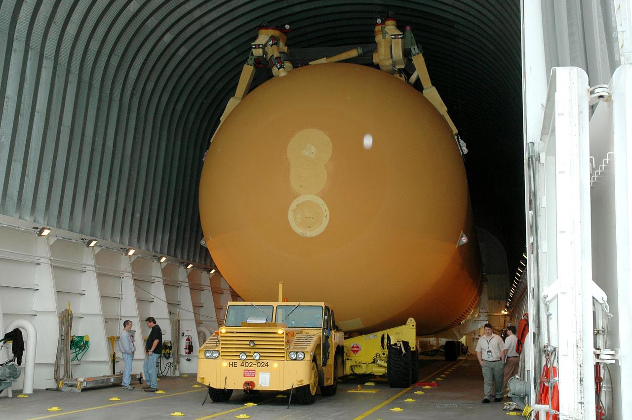
KENNEDY SPACE CENTER, FLA. - The second redesigned External Tank (ET-121) is ready to leave the barge at the Turn Basin near the Vehicle Assembly Building (VAB) after its 900-mile journey at sea from the Michoud Assembly Facility in New Orleans. It will then be offloaded and transported to the Vehicle Assembly Building at NASA’s Kennedy Space Center in Florida. In addition to the Return to Flight modifications, this tank has been outfitted with temperature sensors and accelerometers, used to measure vibration. These sensors will gather information about how the tank performs during flight. The tank is designated for use on Return to Flight mission STS-121, which has a launch window of July 12 to July 31, 2005.
KENNEDY SPACE CENTER, FLA. - The second redesigned External Tank (ET-121) moves toward the open doors in the Vehicle Assembly Building. The tank recently arrived at the Turn Basin after its 900-mile journey at sea from the Michoud Assembly Facility in New Orleans. In addition to the Return to Flight modifications, this tank has been outfitted with temperature sensors and accelerometers, used to measure vibration. These sensors will gather information about how the tank performs during flight. The tank is designated for use on Return to Flight mission STS-121, which has a launch window of July 12 to July 31, 2005.
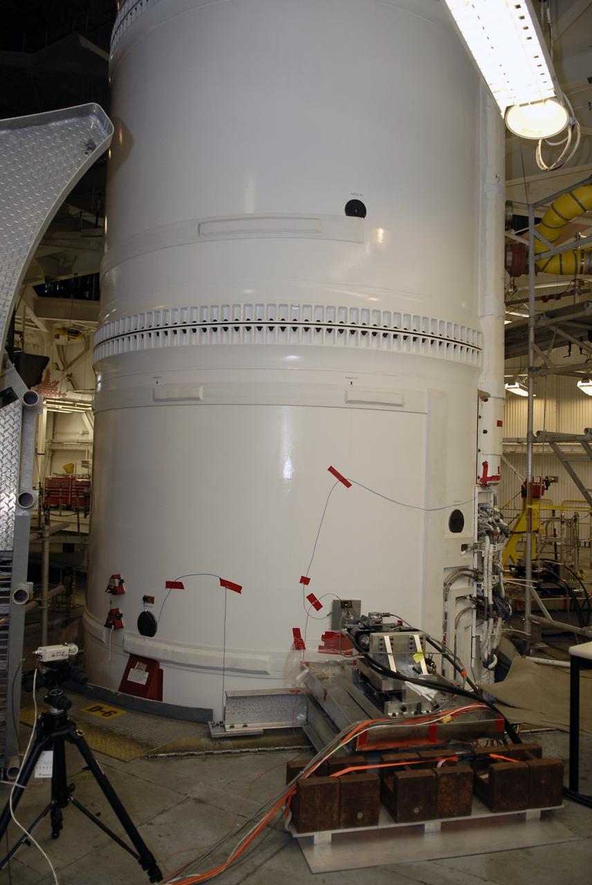
Orion’s service module for NASA’s Artemis 1 mission was moved from a test stand to a test cell inside the Operations and Checkout Building at NASA’s Kennedy Space Center in Florida on May 22, 2019. With microphones, strain gauges and accelerometers attached, the service module will undergo acoustic testing to check for flaws, the latest step in preparing for the agency’s first uncrewed flight test of Orion on the Space Launch System (SLS) rocket. Artemis 1 will be the first mission launching Orion on the SLS rocket from Kennedy’s Launch Pad 39B. The mission will take Orion thousands of miles past the Moon on an approximately three-week test flight. Orion will return to Earth and splashdown in the Pacific Ocean off the coast of California, where it will be retrieved and returned to Kennedy.
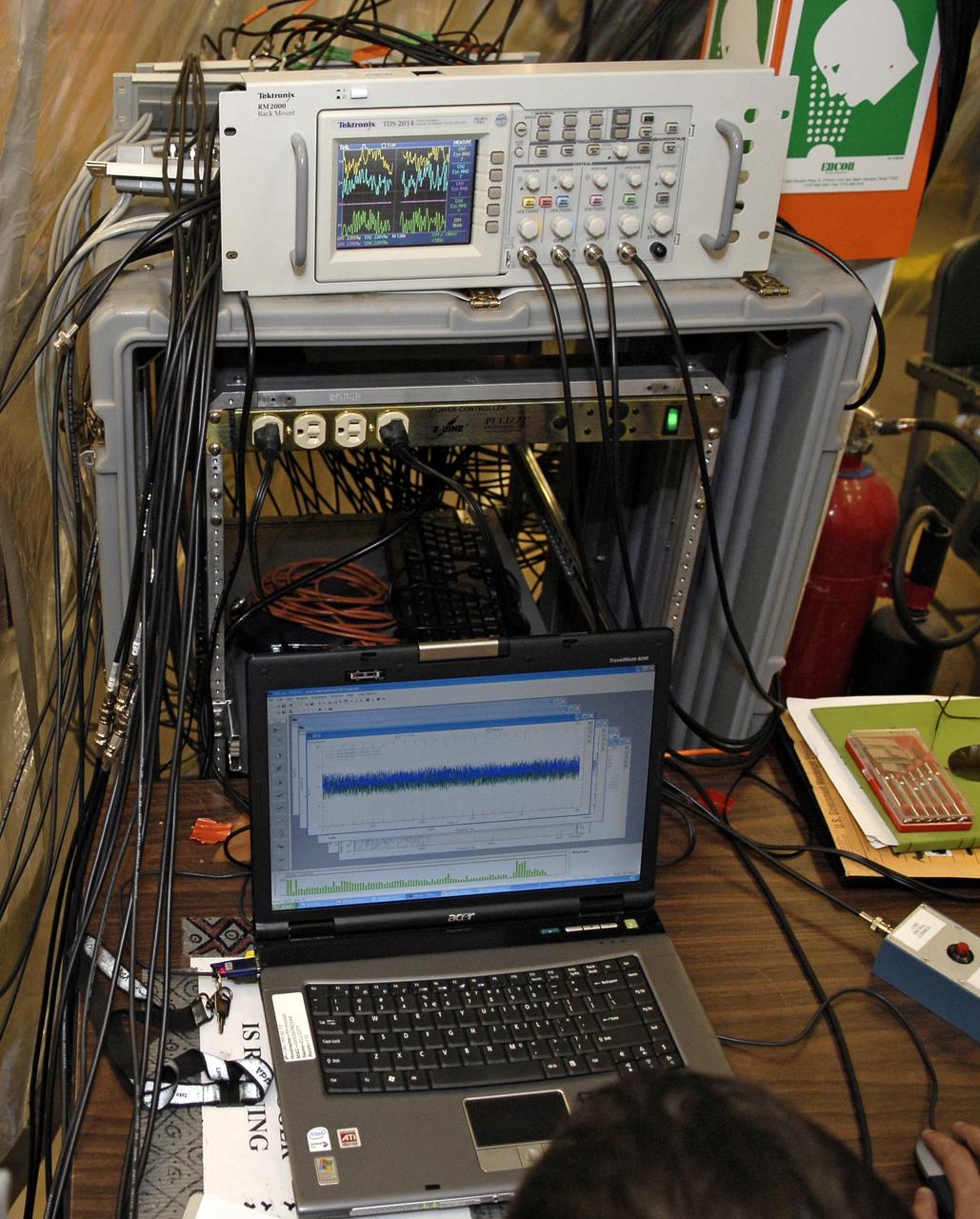
CAPE CANAVERAL, Fla. – In the Vehicle Assembly Building's High Bay 4 at NASA's Kennedy Space Center in Florida, equipment collects data from a sway test being conducted on the Ares I-X launch vehicle. The test is simulating conditions the rocket could experience during rollout to Launch Pad 39B, wind conditions at the pad and first-stage ignition. During the test, vibrations are mechanically induced into the rocket by four hydraulic shakers and a sway is manually introduced for lateral motion to measure the vehicle's response. A total of 44 accelerometers are installed on the flight test vehicle that required more than 27,000 feet of cable. Part of the Constellation Program, the Ares I-X is the test vehicle for the Ares I, which is the essential core of a space transportation system that eventually will carry crewed missions back to the moon, on to Mars and out into the solar system . The Ares I-X flight test is targeted for Oct. 31. Photo credit: NASA/Kim Shiflett
CAPE CANAVERAL, Fla. – In the Vehicle Assembly Building's High Bay 4 at NASA's Kennedy Space Center in Florida, equipment is set up to conduct a sway test on the Ares I-X launch vehicle. The test is simulating conditions the rocket could experience during rollout to Launch Pad 39B, wind conditions at the pad and first-stage ignition. During the test, vibrations are mechanically induced into the rocket by four hydraulic shakers and a sway is manually introduced for lateral motion to measure the vehicle's response. A total of 44 accelerometers are installed on the flight test vehicle that required more than 27,000 feet of cable. Part of the Constellation Program, the Ares I-X is the test vehicle for the Ares I, which is the essential core of a space transportation system that eventually will carry crewed missions back to the moon, on to Mars and out into the solar system . The Ares I-X flight test is targeted for Oct. 31. Photo credit: NASA/Kim Shiflett
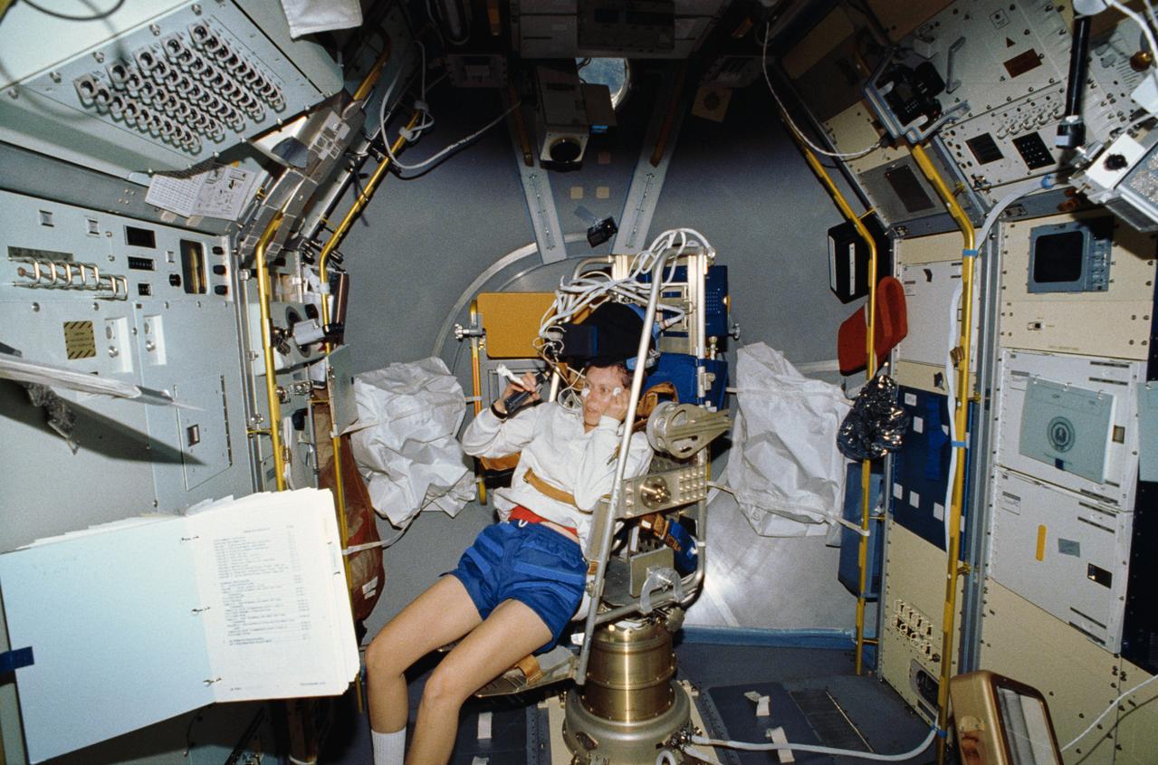
STS042-06-031 (30 Jan 1992) - - - STS-42 Payload Specialist Roberta L. Bondar gets into the Microgravity Vestibular Investigations (MVI) rotator chair to begin an experiment. The chair is mounted in the center aisle of the International Microgravity Laboratory 1 (IML-1) Spacelab (SL) module. Just above Bondar's head is the helmet assembly which is outfitted with accelerometers to measure head movements and visors that fit over each eye independently to provide visual stimuli. The chair system has three movement patterns: "sinusoidal" or traveling predictably back and forth over the same distance at a constant speed; "pseudorandom" or moving back and forth over varying distances; and "stepped" or varying speeds beginning and stopping suddenly.
CAPE CANAVERAL, Fla. – Work platforms surround the Ares I-X launch vehicle in the Vehicle Assembly Building's High Bay 4 at NASA's Kennedy Space Center in Florida. The rocket has undergone a sway test that simulated conditions the rocket could experience during rollout to Launch Pad 39B, wind conditions at the pad and first-stage ignition. During the test, vibrations are mechanically induced into the rocket by four hydraulic shakers and a sway is manually introduced for lateral motion to measure the vehicle's response. A total of 44 accelerometers are installed on the flight test vehicle that required more than 27,000 feet of cable. Part of the Constellation Program, the Ares I-X is the test vehicle for the Ares I, which is the essential core of a space transportation system that eventually will carry crewed missions back to the moon, on to Mars and out into the solar system . The Ares I-X flight test is targeted for Oct. 31. Photo credit: NASA/Kim Shiflett
Orion’s service module for NASA’s Artemis 1 mission was moved from a test stand to a test cell inside the Operations and Checkout Building at NASA’s Kennedy Space Center in Florida on May 22, 2019. With microphones, strain gauges and accelerometers attached, the service module will undergo acoustic testing to check for flaws, the latest step in preparing for the agency’s first uncrewed flight test of Orion on the Space Launch System (SLS) rocket. Artemis 1 will be the first mission launching Orion on the SLS rocket from Kennedy’s Launch Pad 39B. The mission will take Orion thousands of miles past the Moon on an approximately three-week test flight. Orion will return to Earth and splashdown in the Pacific Ocean off the coast of California, where it will be retrieved and returned to Kennedy.
CAPE CANAVERAL, Fla. – In the Vehicle Assembly Building's High Bay 4 at NASA's Kennedy Space Center in Florida, wires are taped to the Ares I-X launch vehicle for the sway test being conducted. The test is simulating conditions the rocket could experience during rollout to Launch Pad 39B, wind conditions at the pad and first-stage ignition. During the test, vibrations are mechanically induced into the rocket by four hydraulic shakers and a sway is manually introduced for lateral motion to measure the vehicle's response. A total of 44 accelerometers are installed on the flight test vehicle that required more than 27,000 feet of cable. Part of the Constellation Program, the Ares I-X is the test vehicle for the Ares I, which is the essential core of a space transportation system that eventually will carry crewed missions back to the moon, on to Mars and out into the solar system . The Ares I-X flight test is targeted for Oct. 31. Photo credit: NASA/Kim Shiflett
Orion’s service module for NASA’s Artemis 1 mission was moved from a test stand to a test cell inside the Operations and Checkout Building at NASA’s Kennedy Space Center in Florida on May 22, 2019. With microphones, strain gauges and accelerometers attached, the service module will undergo acoustic testing to check for flaws, the latest step in preparing for the agency’s first uncrewed flight test of Orion on the Space Launch System (SLS) rocket. Artemis 1 will be the first mission launching Orion on the SLS rocket from Kennedy’s Launch Pad 39B. The mission will take Orion thousands of miles past the Moon on an approximately three-week test flight. Orion will return to Earth and splashdown in the Pacific Ocean off the coast of California, where it will be retrieved and returned to Kennedy.
Orion’s service module for NASA’s Artemis 1 mission was moved from a test stand to a test cell inside the Operations and Checkout Building at NASA’s Kennedy Space Center in Florida on May 22, 2019. With microphones, strain gauges and accelerometers attached, the service module will undergo acoustic testing to check for flaws, the latest step in preparing for the agency’s first uncrewed flight test of Orion on the Space Launch System (SLS) rocket. Artemis 1 will be the first mission launching Orion on the SLS rocket from Kennedy’s Launch Pad 39B. The mission will take Orion thousands of miles past the Moon on an approximately three-week test flight. Orion will return to Earth and splashdown in the Pacific Ocean off the coast of California, where it will be retrieved and returned to Kennedy.
CAPE CANAVERAL, Fla. – Work platforms surround the Ares I-X launch vehicle in the Vehicle Assembly Building's High Bay 4 at NASA's Kennedy Space Center in Florida. The rocket has undergone a sway test that simulated conditions the rocket could experience during rollout to Launch Pad 39B, wind conditions at the pad and first-stage ignition. During the test, vibrations are mechanically induced into the rocket by four hydraulic shakers and a sway is manually introduced for lateral motion to measure the vehicle's response. A total of 44 accelerometers are installed on the flight test vehicle that required more than 27,000 feet of cable. Part of the Constellation Program, the Ares I-X is the test vehicle for the Ares I, which is the essential core of a space transportation system that eventually will carry crewed missions back to the moon, on to Mars and out into the solar system . The Ares I-X flight test is targeted for Oct. 31. Photo credit: NASA/Kim Shiflett
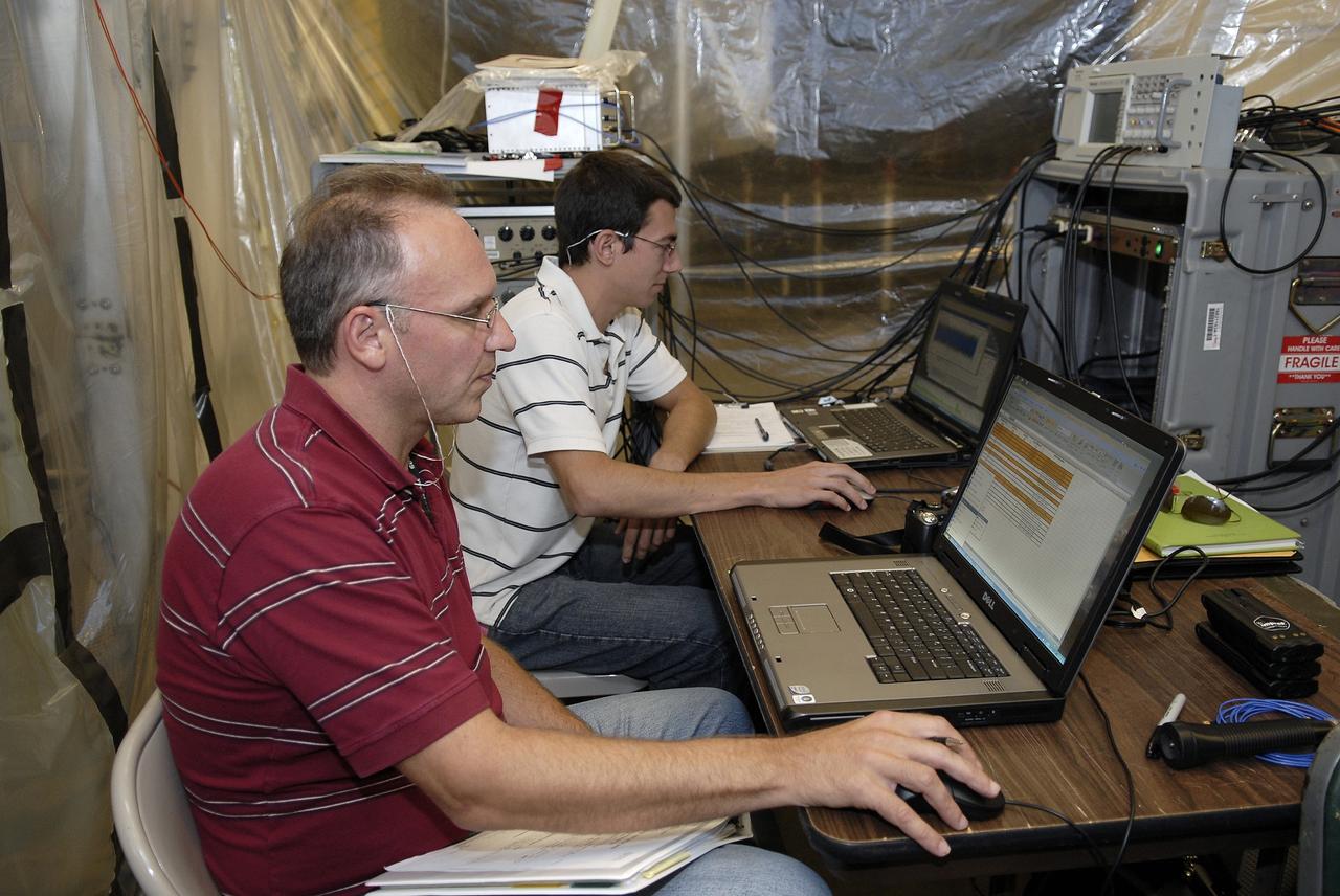
CAPE CANAVERAL, Fla. – In the Vehicle Assembly Building's High Bay 4 at NASA's Kennedy Space Center in Florida, technicians are monitoring a sway test on the Ares I-X launch vehicle. The test is simulating conditions the rocket could experience during rollout to Launch Pad 39B, wind conditions at the pad and first-stage ignition. During the test, vibrations are mechanically induced into the rocket by four hydraulic shakers and a sway is manually introduced for lateral motion to measure the vehicle's response. A total of 44 accelerometers are installed on the flight test vehicle that required more than 27,000 feet of cable. Part of the Constellation Program, the Ares I-X is the test vehicle for the Ares I, which is the essential core of a space transportation system that eventually will carry crewed missions back to the moon, on to Mars and out into the solar system . The Ares I-X flight test is targeted for Oct. 31. Photo credit: NASA/Kim Shiflett
Orion’s service module for NASA’s Artemis 1 mission was moved from a test stand to a test cell inside the Operations and Checkout Building at NASA’s Kennedy Space Center in Florida on May 22, 2019. With microphones, strain gauges and accelerometers attached, the service module will undergo acoustic testing to check for flaws, the latest step in preparing for the agency’s first uncrewed flight test of Orion on the Space Launch System (SLS) rocket. Artemis 1 will be the first mission launching Orion on the SLS rocket from Kennedy’s Launch Pad 39B. The mission will take Orion thousands of miles past the Moon on an approximately three-week test flight. Orion will return to Earth and splashdown in the Pacific Ocean off the coast of California, where it will be retrieved and returned to Kennedy.
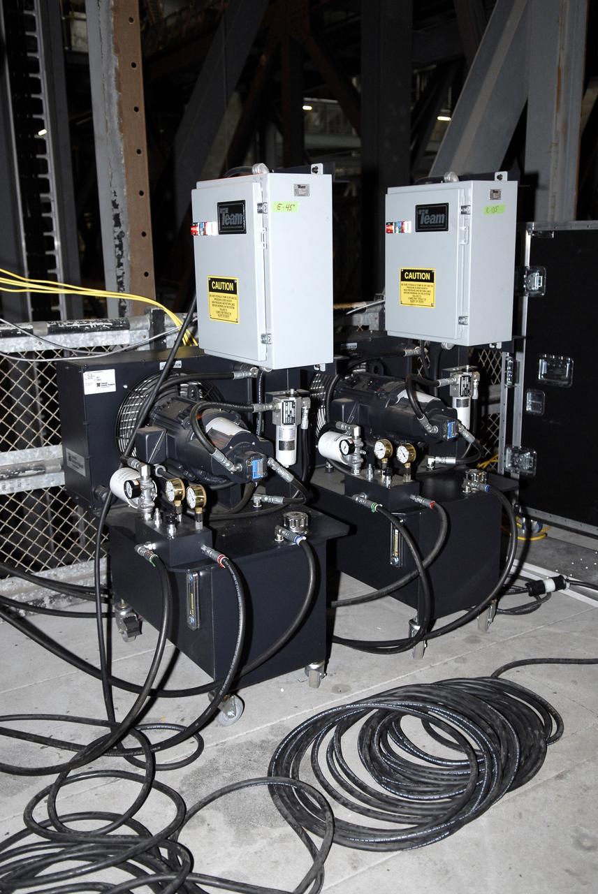
CAPE CANAVERAL, Fla. – In the Vehicle Assembly Building's High Bay 4 at NASA's Kennedy Space Center in Florida, equipment is set up to conduct a sway test on the Ares I-X launch vehicle. The test is simulating conditions the rocket could experience during rollout to Launch Pad 39B, wind conditions at the pad and first-stage ignition. During the test, vibrations are mechanically induced into the rocket by four hydraulic shakers and a sway is manually introduced for lateral motion to measure the vehicle's response. A total of 44 accelerometers are installed on the flight test vehicle that required more than 27,000 feet of cable. Part of the Constellation Program, the Ares I-X is the test vehicle for the Ares I, which is the essential core of a space transportation system that eventually will carry crewed missions back to the moon, on to Mars and out into the solar system . The Ares I-X flight test is targeted for Oct. 31. Photo credit: NASA/Kim Shiflett
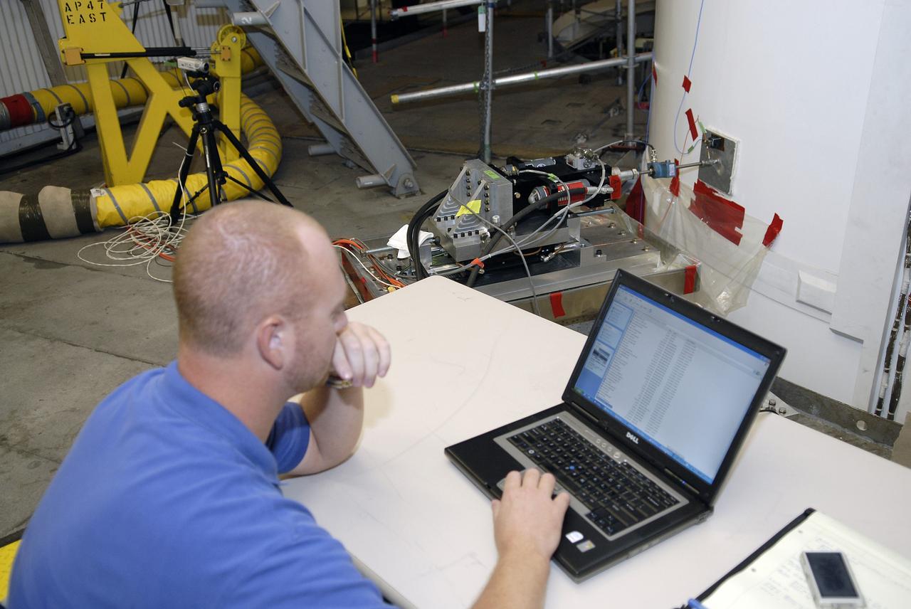
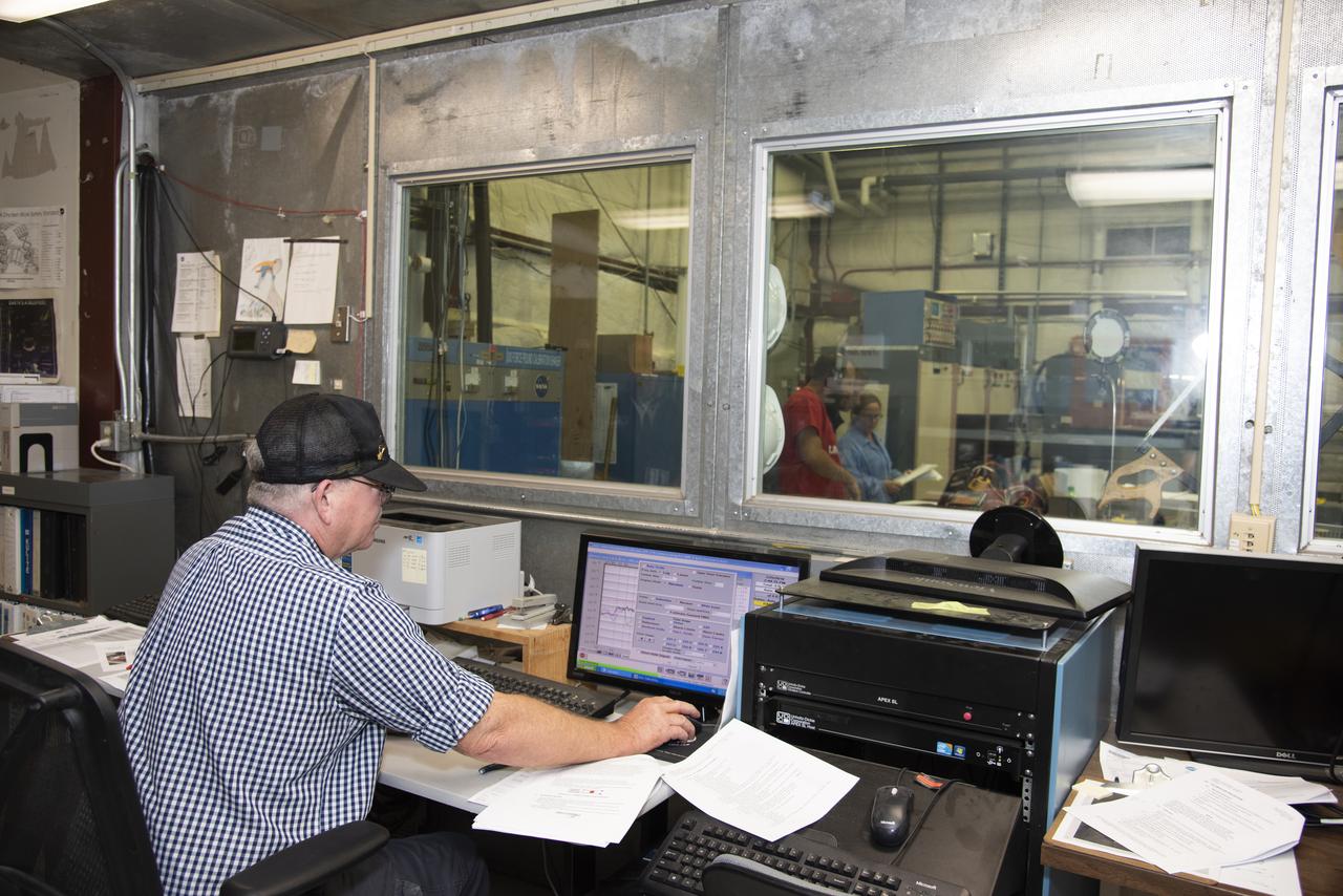
CAPE CANAVERAL, Fla. – In the Vehicle Assembly Building's High Bay 4 at NASA's Kennedy Space Center in Florida, a worker monitors data collected during a sway test on the Ares I-X launch vehicle. The test is simulating conditions the rocket could experience during rollout to Launch Pad 39B, wind conditions at the pad and first-stage ignition. During the test, vibrations are mechanically induced into the rocket by four hydraulic shakers and a sway is manually introduced for lateral motion to measure the vehicle's response. A total of 44 accelerometers are installed on the flight test vehicle that required more than 27,000 feet of cable. Part of the Constellation Program, the Ares I-X is the test vehicle for the Ares I, which is the essential core of a space transportation system that eventually will carry crewed missions back to the moon, on to Mars and out into the solar system . The Ares I-X flight test is targeted for Oct. 31. Photo credit: NASA/Kim Shiflett
STS042-27-037 (22-30 Jan. 1992) --- Astronaut David C. Hilmers, STS-42 mission specialist, wearing a helmet assembly, sits in the Microgravity Vestibular Investigation (MVI) rotating chair. The scene is in the International Microgravity Laboratory (IML-1) science module aboard Discovery. Hilmers, a mission specialist, and six other crewmembers spent more than eight days in Earth-orbit conducting experiments. Hilmer's helmet assembly is outfitted with accelerometers to measure head movements and visors that fit over each eye independently to provide visual stimuli. The chair system has three movement patterns: "sinusoidal" or traveling predictably back and forth over the same distance at a constant speed; "pseudorandom" or moving back and forth over the varying distances; and "stepped" or varying speeds beginning and stopping suddenly.
CAPE CANAVERAL, Fla. – Work platforms surround the Ares I-X launch vehicle in the Vehicle Assembly Building's High Bay 4 at NASA's Kennedy Space Center in Florida. The rocket has undergone a sway test that simulated conditions the rocket could experience during rollout to Launch Pad 39B, wind conditions at the pad and first-stage ignition. During the test, vibrations are mechanically induced into the rocket by four hydraulic shakers and a sway is manually introduced for lateral motion to measure the vehicle's response. A total of 44 accelerometers are installed on the flight test vehicle that required more than 27,000 feet of cable. Part of the Constellation Program, the Ares I-X is the test vehicle for the Ares I, which is the essential core of a space transportation system that eventually will carry crewed missions back to the moon, on to Mars and out into the solar system . The Ares I-X flight test is targeted for Oct. 31. Photo credit: NASA/Kim Shiflett
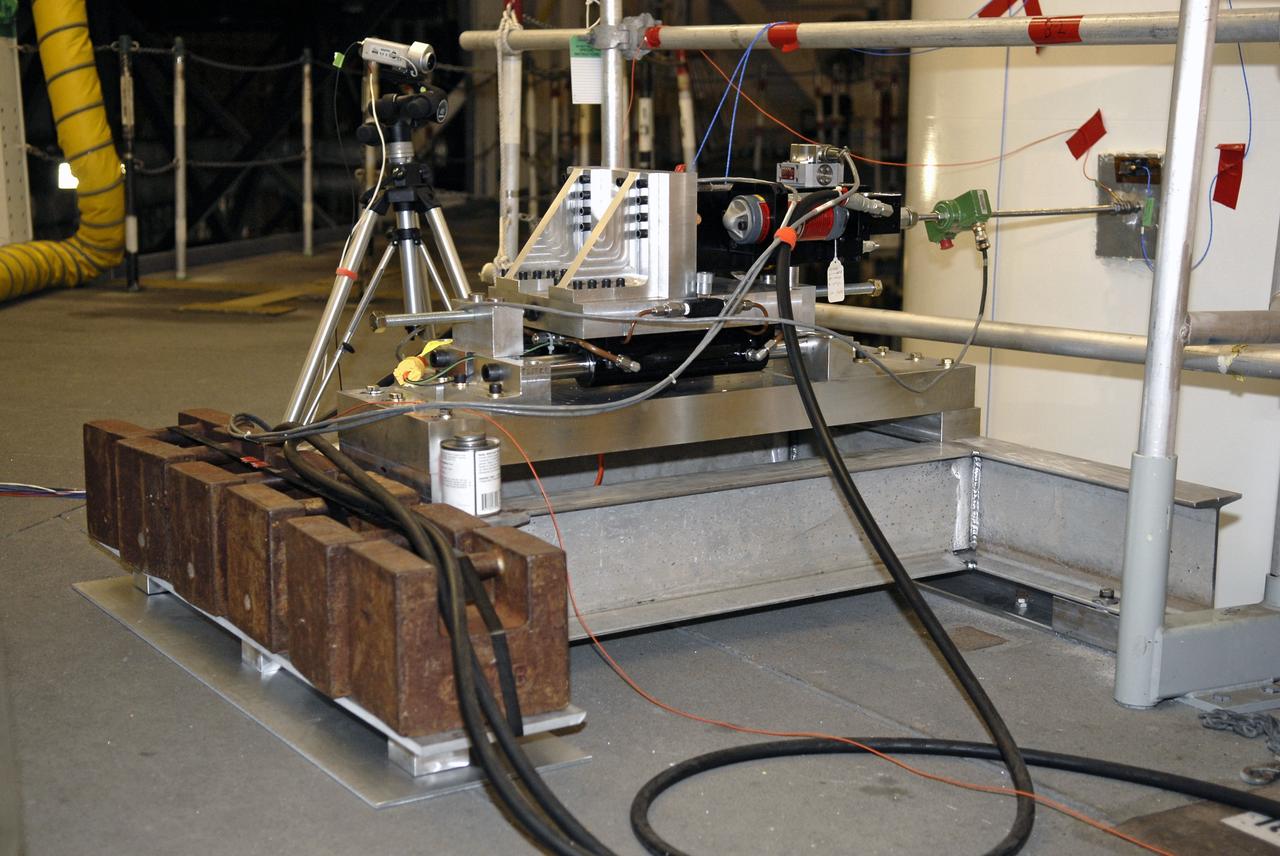
CAPE CANAVERAL, Fla. – In the Vehicle Assembly Building's High Bay 4 at NASA's Kennedy Space Center in Florida, equipment is set up to conduct a sway test on the Ares I-X launch vehicle. The test will simulate conditions the rocket could experience during rollout to Launch Pad 39B, wind conditions at the pad and first-stage ignition. During the test, vibrations are mechanically induced into the rocket by four hydraulic shakers and a sway is manually introduced for lateral motion to measure the vehicle's response. A total of 44 accelerometers are installed on the flight test vehicle that required more than 27,000 feet of cable. Part of the Constellation Program, the Ares I-X is the test vehicle for the Ares I, which is the essential core of a space transportation system that eventually will carry crewed missions back to the moon, on to Mars and out into the solar system . The Ares I-X flight test is targeted for Oct. 31. Photo credit: NASA/Kim Shiflett
Orion’s service module for NASA’s Artemis 1 mission was moved from a test stand to a test cell inside the Operations and Checkout Building at NASA’s Kennedy Space Center in Florida on May 22, 2019. With microphones, strain gauges and accelerometers attached, the service module will undergo acoustic testing to check for flaws, the latest step in preparing for the agency’s first uncrewed flight test of Orion on the Space Launch System (SLS) rocket. Artemis 1 will be the first mission launching Orion on the SLS rocket from Kennedy’s Launch Pad 39B. The mission will take Orion thousands of miles past the Moon on an approximately three-week test flight. Orion will return to Earth and splashdown in the Pacific Ocean off the coast of California, where it will be retrieved and returned to Kennedy.
STS040-211-020 (5-14 June 1991) --- Vestibular experiment activities were captured onboard Columbia's Spacelab Life Sciences (SLS-1) module in this 35mm scene. Astronaut James P. Bagian, STS-40 mission specialist, is in a rotating chair while wearing an accelometer and electrodes to record head motion and horizontal and vertical eye movements during the rotations. Payload specialist Millie Hughes-Fulford, lower left, assists with the test.
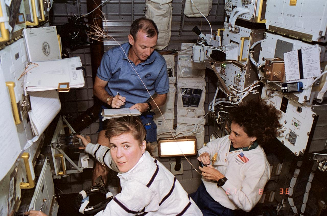
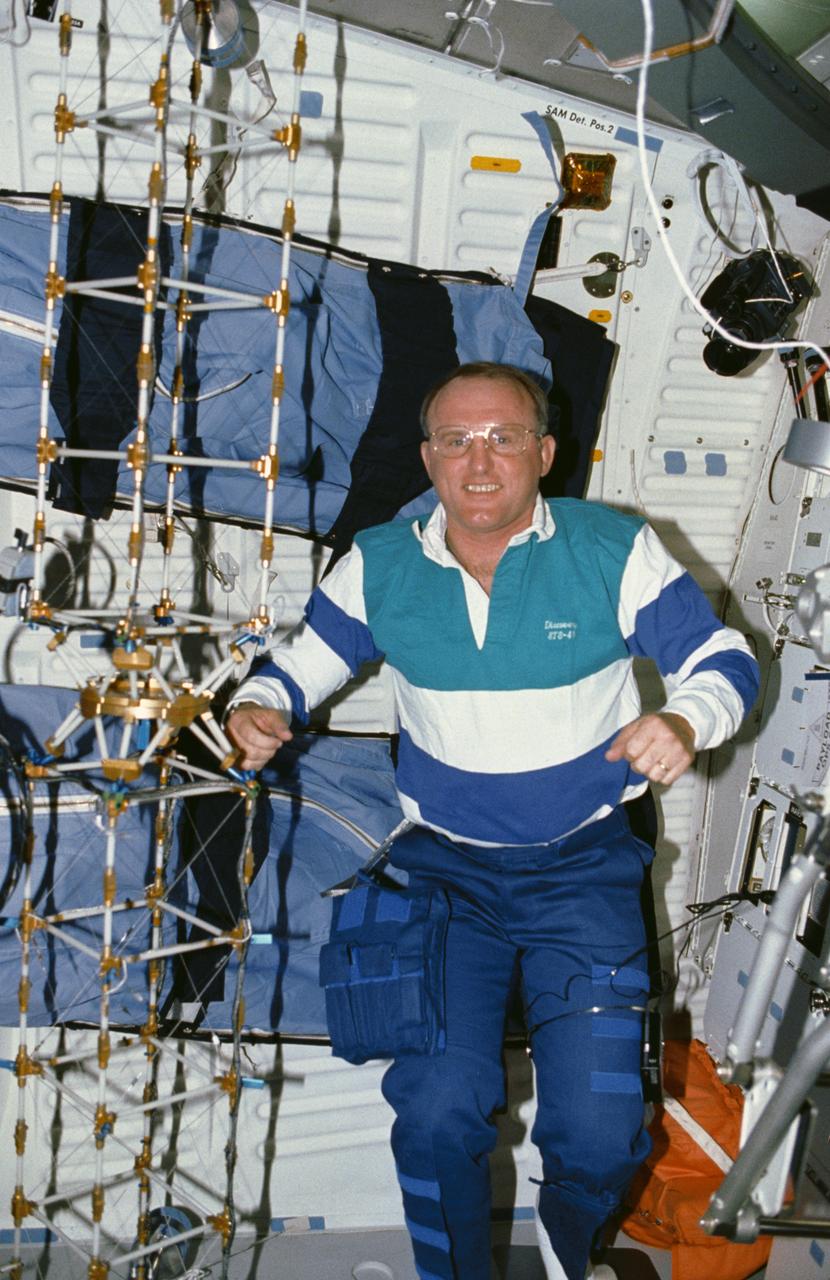
STS057-39-001 (27 June 1993) --- This high angle shot inside the SPACEHAB module, onboard the Space Shuttle Endeavour, typifies the pace of activity conducted there during the ten-day STS-57 mission. Astronaut Janice E. Voss (foreground), mission specialist, works with biomaterials products, while astronauts Brian Duffy, pilot, and Nancy J. Sherlock, mission specialist, participate in other tasks.
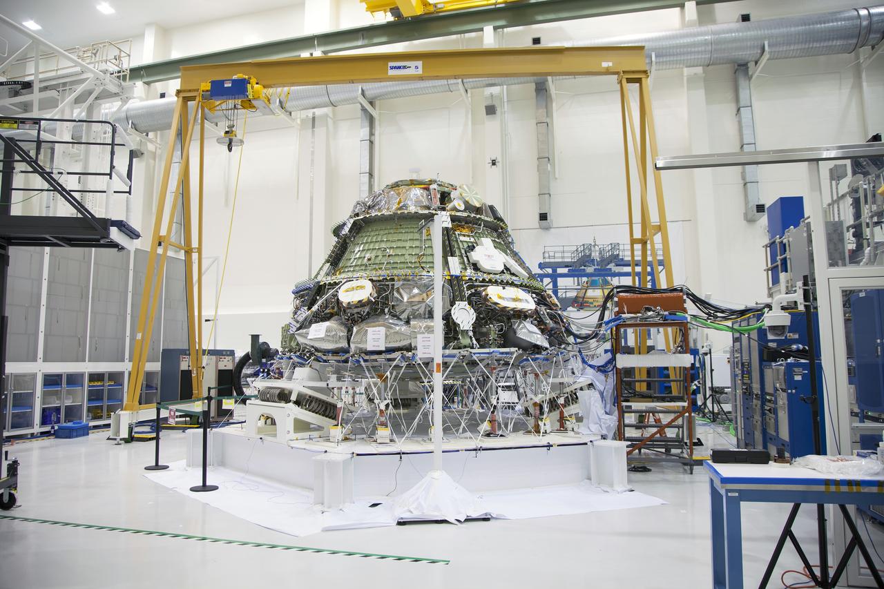
CAPE CANAVERAL, Fla. - Inside the Operations and Checkout Building high bay at NASA’s Kennedy Space Center in Florida, the Orion crew module is positioned on a special portable test chamber and prepared for a multi-point random vibration test. Accelerometers and strain gages have been attached to Orion in various locations. During a series of tests, each lasting only 30 seconds, Orion will be subjected to gradually increasing levels of vibrations that represent levels the vehicle would experience during launch, orbit and descent. The data is reviewed in order to assess the health of the crew module. Orion is the exploration spacecraft designed to carry astronauts to destinations not yet explored by humans, including an asteroid and Mars. It will have emergency abort capability, sustain the crew during space travel and provide safe re-entry from deep space return velocities. The first unpiloted test flight of the Orion is scheduled to launch later this year atop a Delta IV rocket and in 2017 on NASA’s Space Launch System rocket. For more information, visit http://www.nasa.gov/orion. Photo credit: NASA/Daniel Casper
A NASA team studying the causes of electrical storms and their effects on our home planet achieved a milestone on August 21, 2002, completing the study's longest-duration research flight and monitoring four thunderstorms in succession. Based at the Naval Air Station Key West, Florida, researchers with the Altus Cumulus Electrification Study (ACES) used the Altus II remotely-piloted aircraft to study thunderstorms in the Atlantic Ocean off Key West and the west of the Everglades. Data obtained through sensors mounted to the aircraft will allow researchers in ACES to gauge elements such as lightning activity and the electrical environment in and around storms. By learning more about individual storms, scientists hope to better understand the global water and energy cycle, as well as climate variability. Contained in one portion of the aircraft is a three-axis magnetic search coil, which measures the AC magnetic field; a three-axis electric field change sensor; an accelerometer; and a three-axis magnetometer, which measures the DC magnetic field. With dual goals of gathering weather data safely and testing the adaptability of the uninhabited aircraft, the ACES study is a collaboration among the Marshall Space Flight Center, the University of Alabama in Huntsville, NASA's Goddard Space Flight Center in Greenbelt, Maryland, Pernsylvania State University in University Park, and General Atomics Aeronautical Systems, Inc.
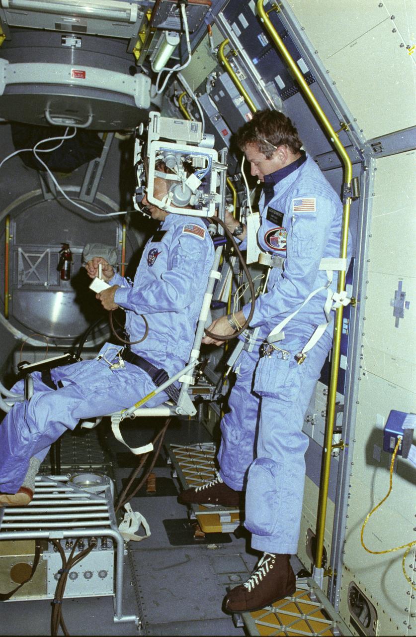
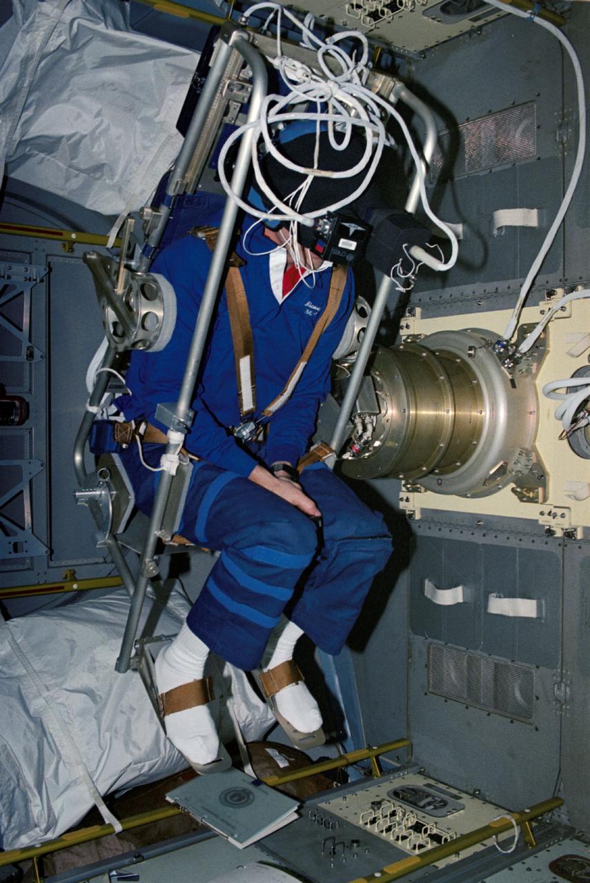
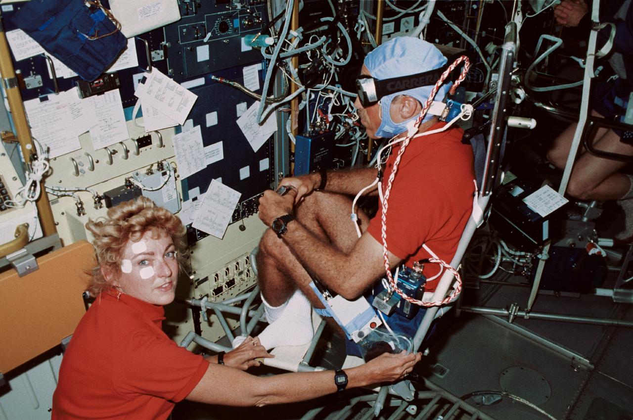
In this photograph, astronauts Owen Garriott on the body restriant system and Byron Lichtenberg prepare for a Vestibular Experiment during the Spacelab-1 mission. The Vestibular Experiments in Space were the study of the interaction among the otoliths, semicircular canals, vision, and spinal reflexes in humans. The main objective was to determine how the body, which receives redundant information for several sensory sources, interprets this information in microgravity. Another objective was to record and characterize the symptoms of space sickness experienced by crewmembers. The body restraint system was a rotating chair with a harness to hold the test subject in place. The crewmember wore an accelerometer and electrodes to record head motion and horizontal and vertical eye movement as the body rotated. The first Spacelab mission, Spacelab-1, sponsored jointly and shared equally by NASA and the European Space Agency, was a multidisciplinary mission; that is, investigations were performed in several different fields of scientific research. The overall goal of the mission was to verify Spacelab performance through a variety of scientific experiments. The Spacelab-1 was launched aboard the Space Shuttle Orbiter Columbia for the STS-9 mission on November 28, 1983. The Marshall Space Flight Center had management responsibilities for the mission.
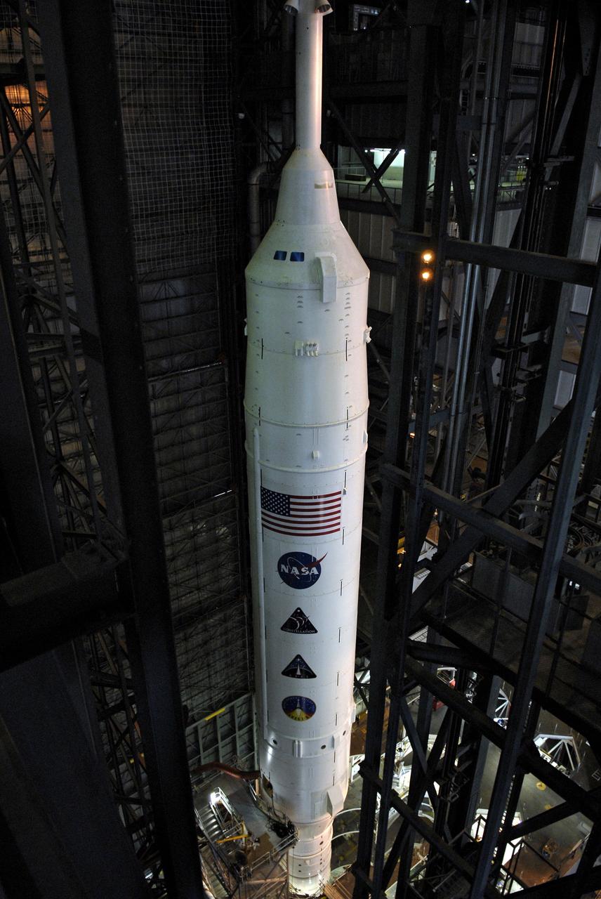
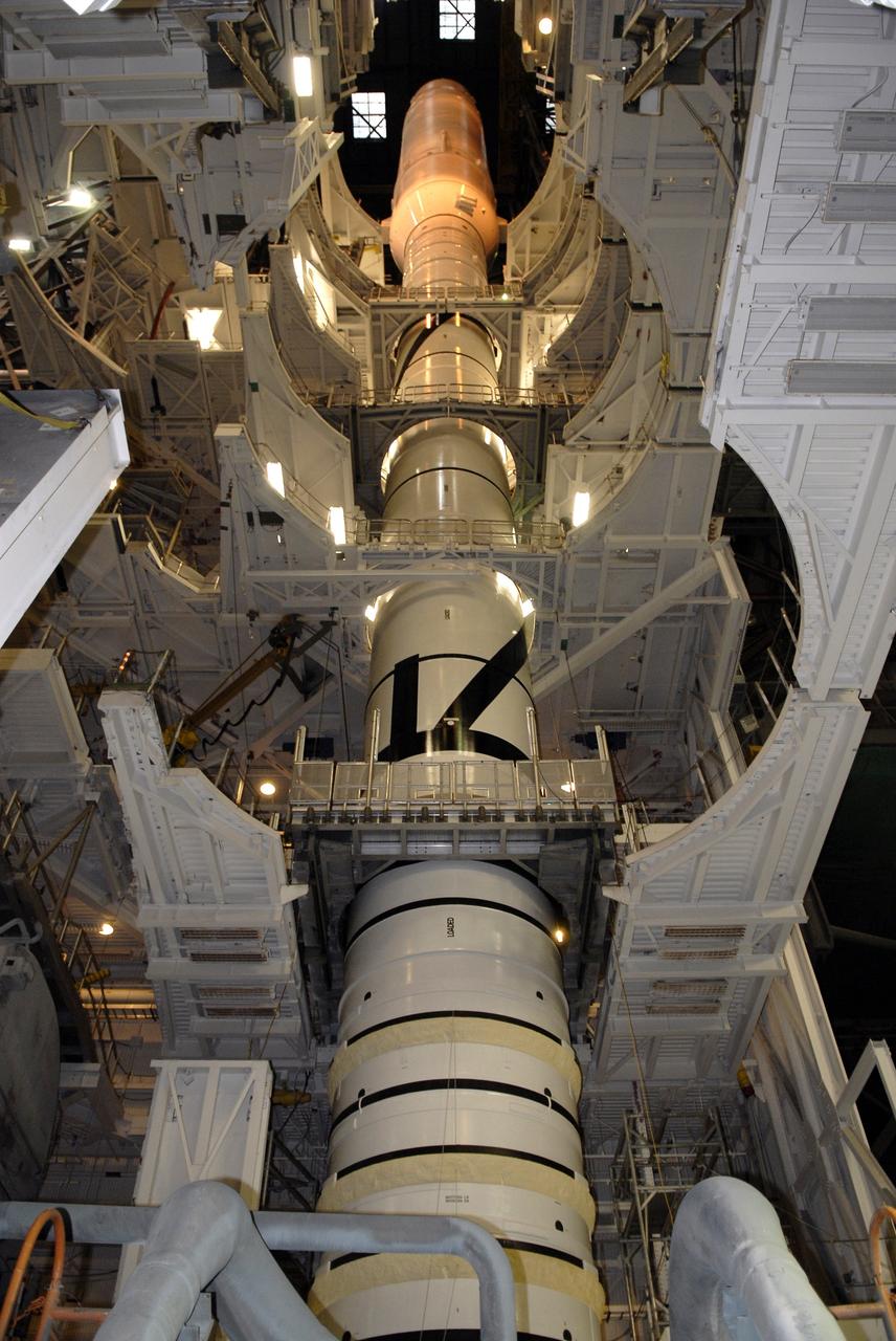
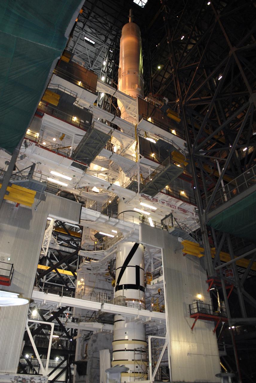
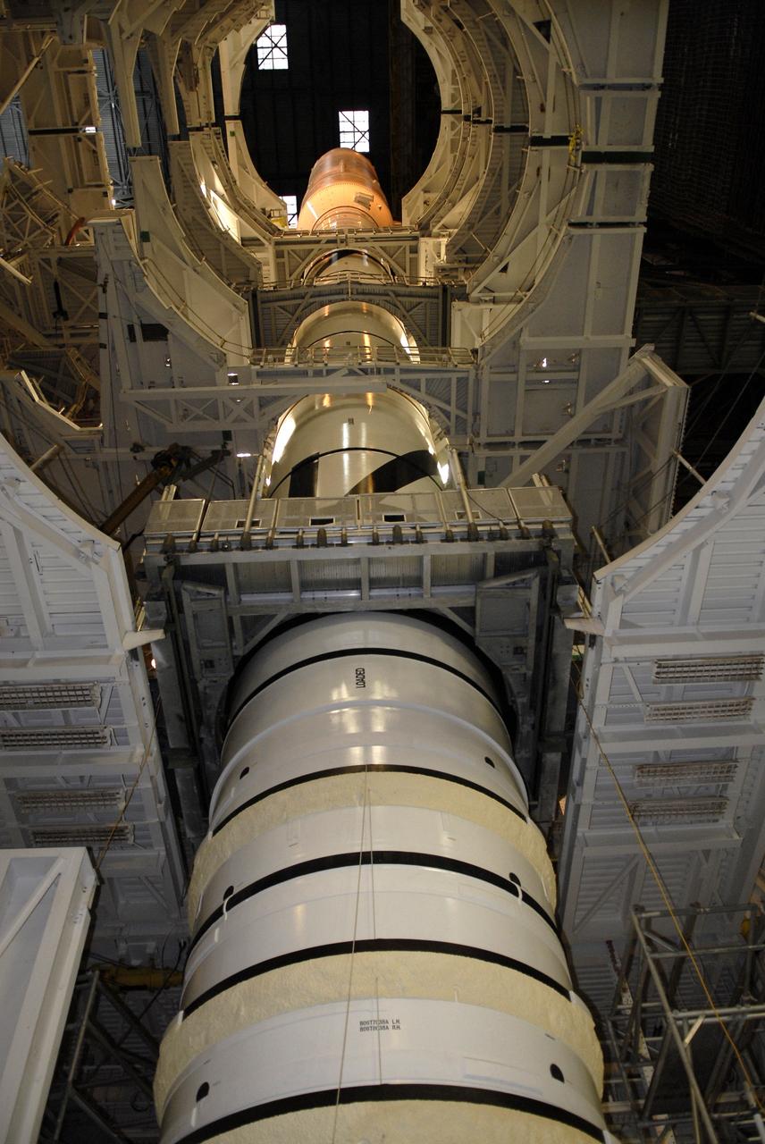
CAPE CANAVERAL, Fla. – This view captures the 327-foot height of the Ares I-X launch vehicle stacked in the Vehicle Assembly Building's High Bay 4 at NASA's Kennedy Space Center in Florida. The rocket is undergoing a sway test. The test is simulating conditions the rocket could experience during rollout to Launch Pad 39B, wind conditions at the pad and first-stage ignition. During the test, vibrations are mechanically induced into the rocket by four hydraulic shakers and a sway is manually introduced for lateral motion to measure the vehicle's response. A total of 44 accelerometers are installed on the flight test vehicle that required more than 27,000 feet of cable. Part of the Constellation Program, the Ares I-X is the test vehicle for the Ares I, which is the essential core of a space transportation system that eventually will carry crewed missions back to the moon, on to Mars and out into the solar system . The Ares I-X flight test is targeted for Oct. 31. Photo credit: NASA/Kim Shiflett
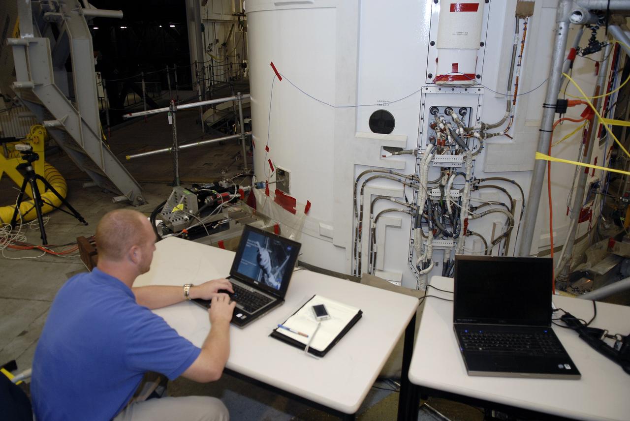
CAPE CANAVERAL, Fla. – In the Vehicle Assembly Building's High Bay 4 at NASA's Kennedy Space Center in Florida, a worker seated at the table monitors data collected during a sway test on the Ares I-X launch vehicle. The test is simulating conditions the rocket could experience during rollout to Launch Pad 39B, wind conditions at the pad and first-stage ignition. During the test, vibrations are mechanically induced into the rocket by four hydraulic shakers and a sway is manually introduced for lateral motion to measure the vehicle's response. A total of 44 accelerometers are installed on the flight test vehicle that required more than 27,000 feet of cable. Part of the Constellation Program, the Ares I-X is the test vehicle for the Ares I, which is the essential core of a space transportation system that eventually will carry crewed missions back to the moon, on to Mars and out into the solar system . The Ares I-X flight test is targeted for Oct. 31. Photo credit: NASA/Kim Shiflett
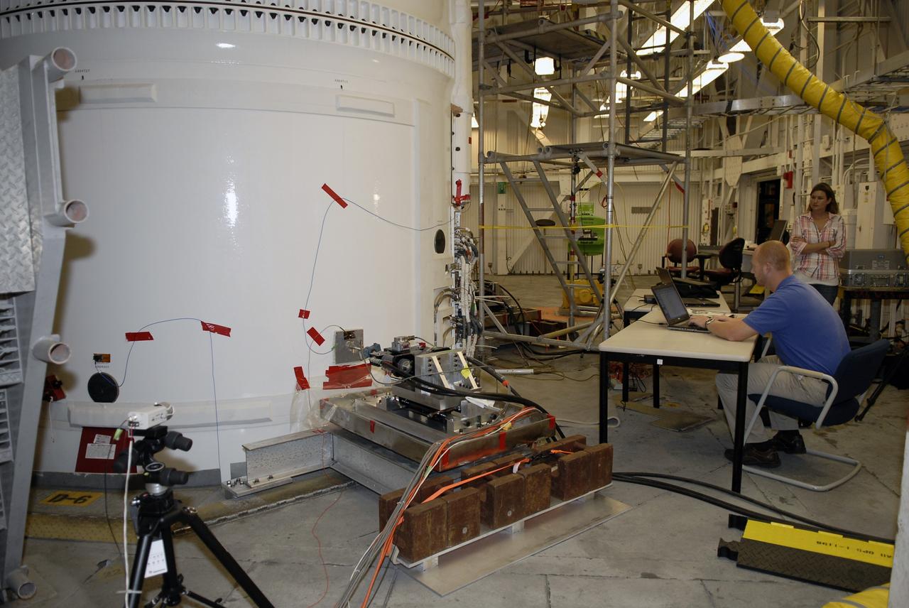
CAPE CANAVERAL, Fla. – In the Vehicle Assembly Building's High Bay 4 at NASA's Kennedy Space Center in Florida, a worker seated at the table monitors data collected during a sway test on the Ares I-X launch vehicle. The test is simulating conditions the rocket could experience during rollout to Launch Pad 39B, wind conditions at the pad and first-stage ignition. During the test, vibrations are mechanically induced into the rocket by four hydraulic shakers and a sway is manually introduced for lateral motion to measure the vehicle's response. A total of 44 accelerometers are installed on the flight test vehicle that required more than 27,000 feet of cable. Part of the Constellation Program, the Ares I-X is the test vehicle for the Ares I, which is the essential core of a space transportation system that eventually will carry crewed missions back to the moon, on to Mars and out into the solar system . The Ares I-X flight test is targeted for Oct. 31. Photo credit: NASA/Kim Shiflett
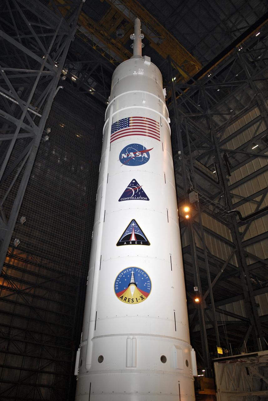
CAPE CANAVERAL, Fla. – Program and NASA decals, along with the U.S. flag, stretch the length of the Ares I-X upper stage stacked in the Vehicle Assembly Building's High Bay 4 at NASA's Kennedy Space Center in Florida. The rocket has undergone a sway test that simulated conditions the rocket could experience during rollout to Launch Pad 39B, wind conditions at the pad and first-stage ignition. During the test, vibrations are mechanically induced into the rocket by four hydraulic shakers and a sway is manually introduced for lateral motion to measure the vehicle's response. A total of 44 accelerometers are installed on the flight test vehicle that required more than 27,000 feet of cable. Part of the Constellation Program, the Ares I-X is the test vehicle for the Ares I, which is the essential core of a space transportation system that eventually will carry crewed missions back to the moon, on to Mars and out into the solar system . The Ares I-X flight test is targeted for Oct. 31. Photo credit: NASA/Kim Shiflett