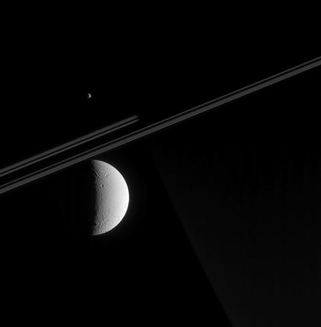
Aligned Moons

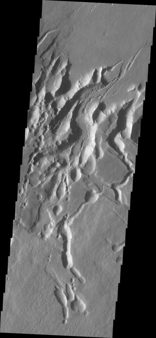
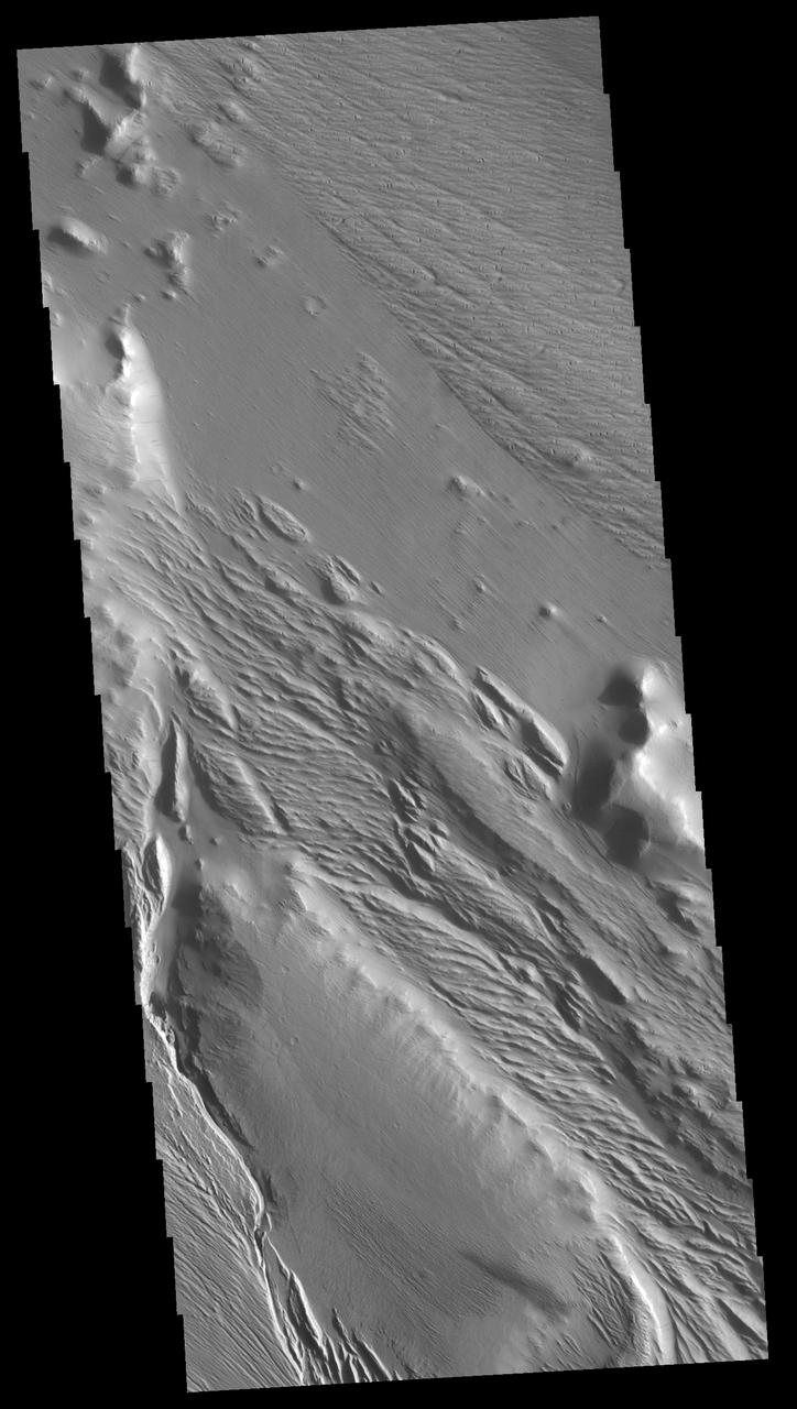
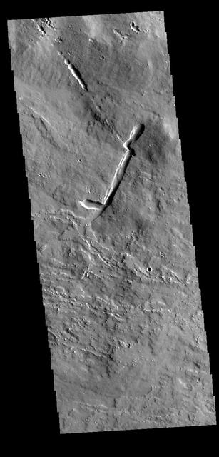
Aligned Defrosting Dunes
When Moons Align
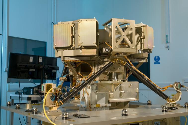
The Mid-Infrared Instrument, a component of NASA James Webb Space Telescope, underwent alignment testing at the Science and Technology Facilities Council Rutherford Appleton Laboratory Space in Oxfordshire, England.

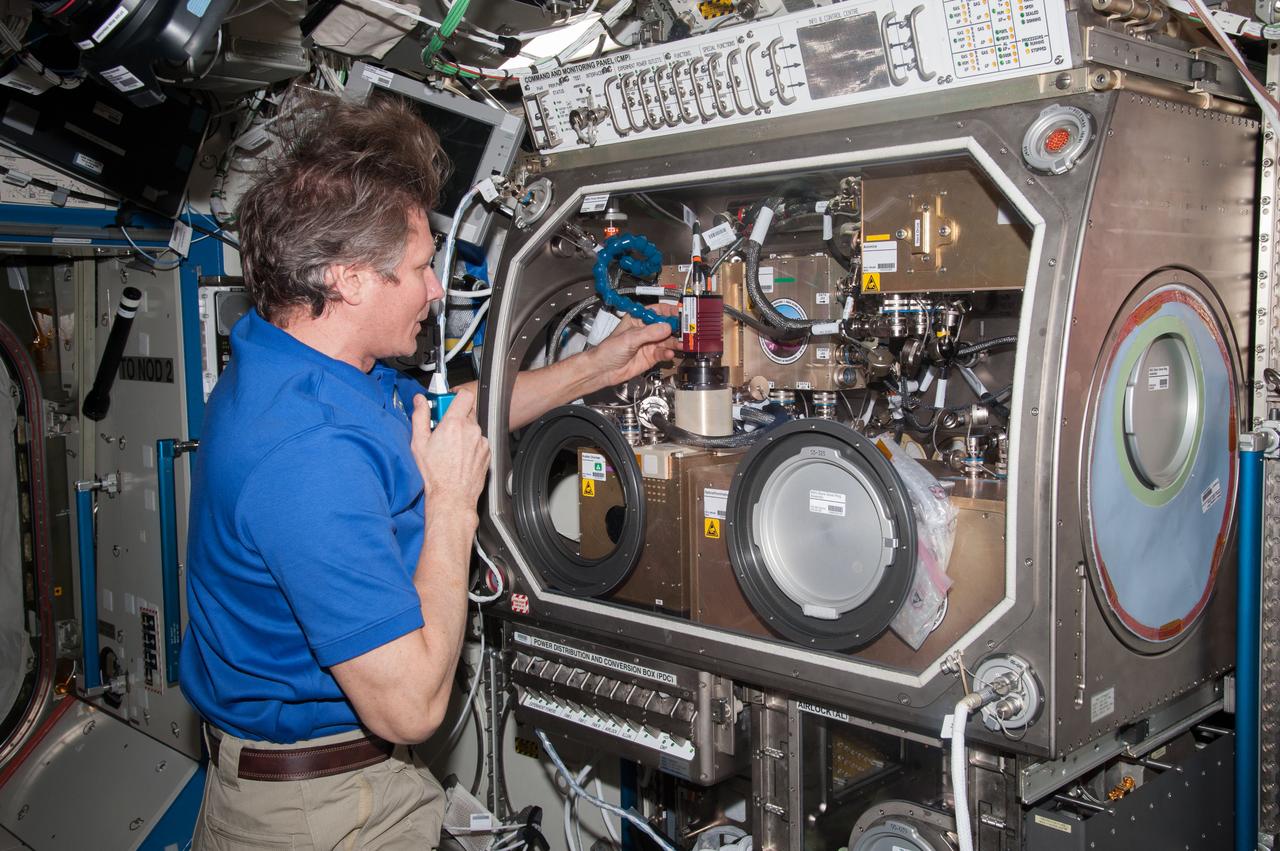
"NASA astronaut Karen Nyberg,Expedition 36 flight engineer,works with the Combustion Integrated Rack (CIR) Alignment Guide Removal.
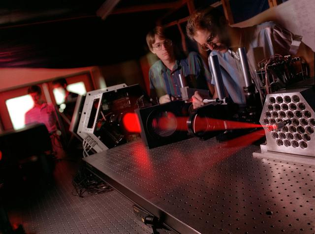
PATRICK CHAMPEY, (LEFT), DICK GATES, (RIGHT), AND BILL PODGORSKI, (SEATED), ALIGN SUN SENSOR TO HI-C TELESCOPE USING THEODOLITE
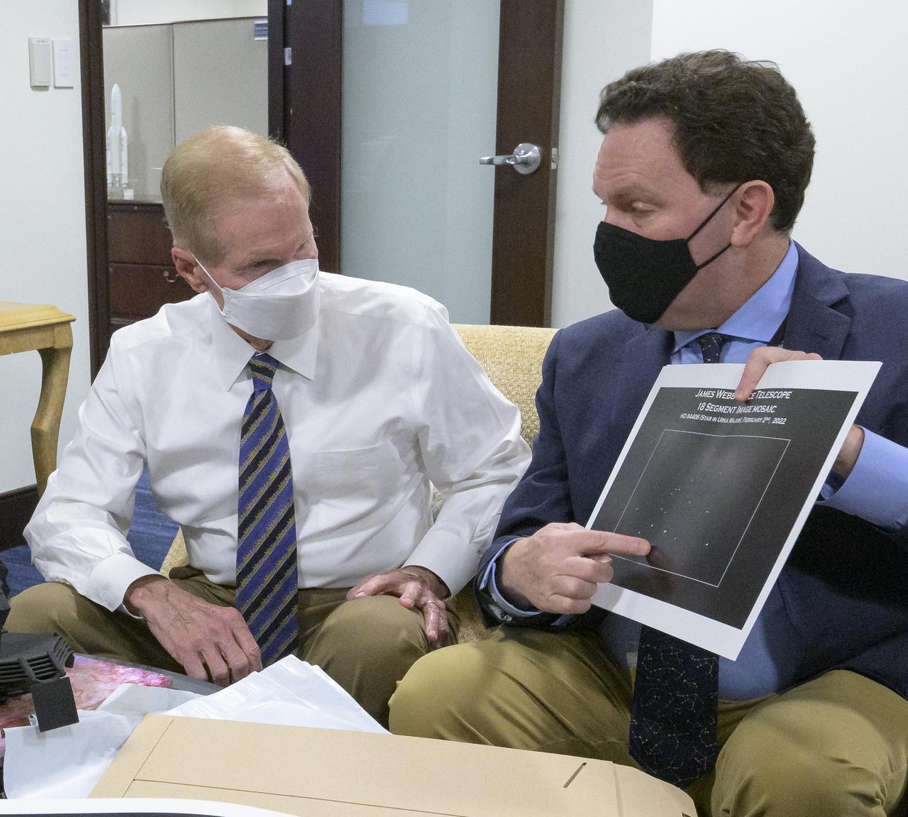
NASA Administrator Bill Nelson, left, is shown an early mirror alignment image from the James Webb Space Telescope, by NASA Webb Optical Telescope Element Manager Lee Feinberg, Monday, Feb., 7, 2022, at the Mary W. Jackson NASA Headquarters building in Washington. This engineering visual, which features 18 unfocused dots of light, demonstrates that the Webb team has successfully identified starlight through each of Webb’s 18 hexagonal mirror segments – the starting point in a months-long process to progressively align the segments into a single, precise mirror to prepare the telescope for science. Photo Credit: (NASA/Bill Ingalls)

Optical engineer, Maurice Stancil, performs final optical alignment metrology measurements prior to the Ocean Color Instrument (OCI) integration to the Plankton, Aerosol, Cloud, ocean Ecosystem (PACE) spacecraft. As he collects data and measures angles on OCI, he is able to determine if the flight hardware is in the correct position. OCI is a highly advanced optical spectrometer that will be used to measure properties of light over portions of the electromagnetic spectrum. It will enable continuous measurement of light at finer wavelength resolution than previous NASA satellite sensors, extending key system ocean color data records for climate studies. OCI is PACE's primary sensor built at Goddard Space Flight Center in Greenbelt, MD.
Inside the Integrated Processing Facility at Vandenberg Space Force Base in California, United Launch Alliance (ULA) technicians prepare to align the two ULA Atlas V rocket payload fairings for NASA’s Landsat 9 satellite on June 22, 2021. The fairings will encapsulate the satellite for its launch atop the Atlas V from Vandenberg in September 2021. The launch is being managed by NASA’s Launch Services Program based at Kennedy Space Center in Florida. Landsat 9 will continue the nearly 50-year legacy of previous Landsat missions. It will monitor key natural and economic resources from orbit. Landsat 9 is managed by the agency’s Goddard Space Flight Center in Greenbelt, Maryland. It will carry two instruments: the Operational Land Imager 2, which collects images of Earth’s landscapes in visible, near-infrared and shortwave infrared light, and the Thermal Infrared Sensor 2, which measures the temperature of land surfaces. Like its predecessors, Landsat 9 is a joint mission between NASA and the U.S. Geological Survey.

Inside the Integrated Processing Facility at Vandenberg Space Force Base in California, United Launch Alliance (ULA) technicians prepare to align the two ULA Atlas V rocket payload fairings for NASA’s Landsat 9 satellite on June 22, 2021. The fairings will encapsulate the satellite for its launch atop the Atlas V from Vandenberg in September 2021. The launch is being managed by NASA’s Launch Services Program based at Kennedy Space Center in Florida. Landsat 9 will continue the nearly 50-year legacy of previous Landsat missions. It will monitor key natural and economic resources from orbit. Landsat 9 is managed by the agency’s Goddard Space Flight Center in Greenbelt, Maryland. It will carry two instruments: the Operational Land Imager 2, which collects images of Earth’s landscapes in visible, near-infrared and shortwave infrared light, and the Thermal Infrared Sensor 2, which measures the temperature of land surfaces. Like its predecessors, Landsat 9 is a joint mission between NASA and the U.S. Geological Survey.
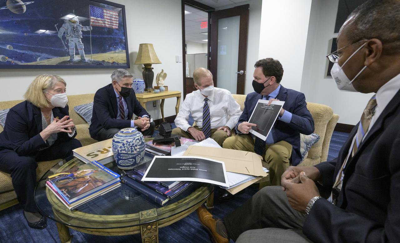
NASA Deputy Administrator Pam Melroy, left, NASA Associate Administrator Bob Cabana, and NASA Administrator Bill Nelson are shown an early mirror alignment image from the James Webb Space Telescope, by NASA Webb Optical Telescope Element Manager Lee Feinberg, as NASA Program Director for the James Webb Space Telescope Program Greg Robinson, right, looks on, Monday, Feb., 7, 2022, at the Mary W. Jackson NASA Headquarters building in Washington. This engineering visual, which features 18 unfocused dots of light, demonstrates that the Webb team has successfully identified starlight through each of Webb’s 18 hexagonal mirror segments – the starting point in a months-long process to progressively align the segments into a single, precise mirror to prepare the telescope for science. Photo Credit: (NASA/Bill Ingalls)
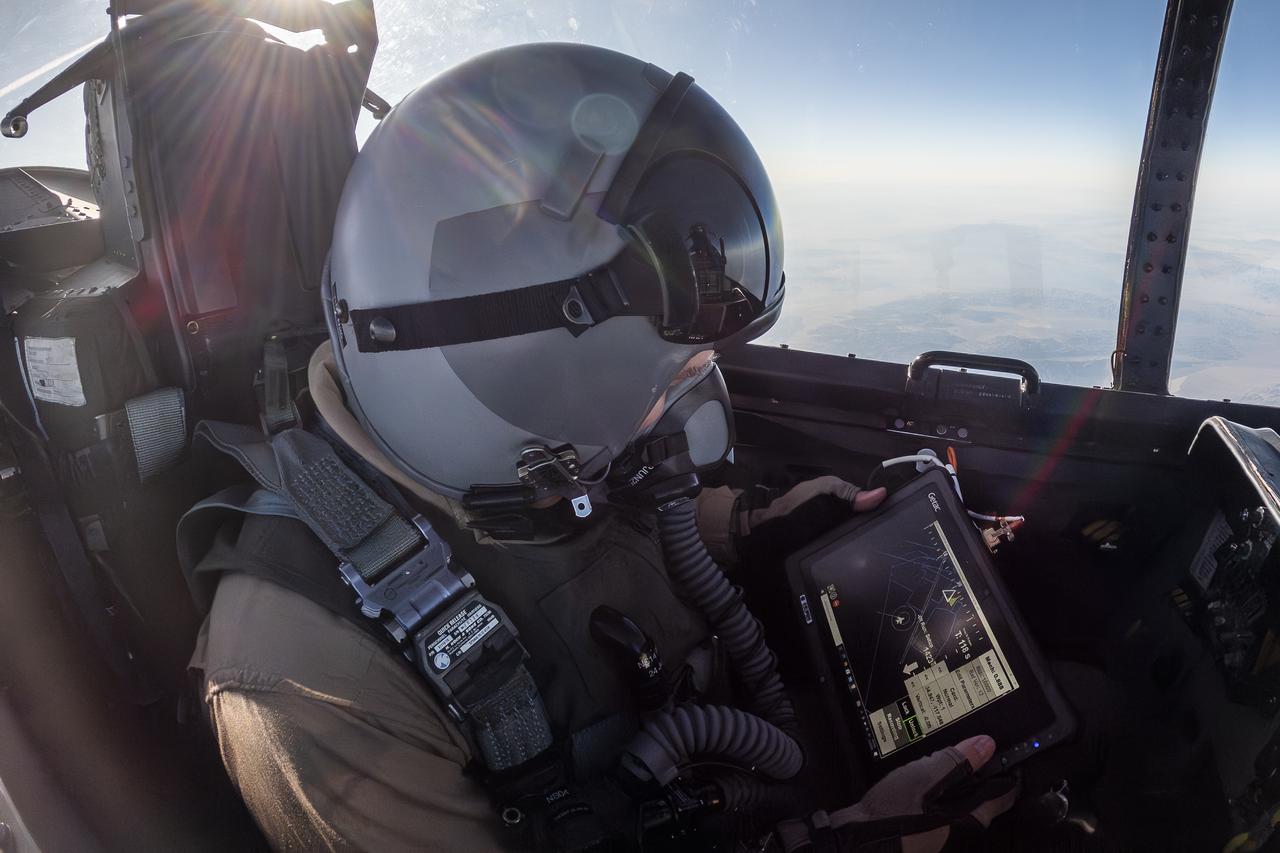
NASA photographer James Ross monitors the Airborne Location Integrating Geospatial Navigation System (ALIGNS) from the backseat of an F-15 near NASA’s Armstrong Flight Research Center in Edwards, California. The ALIGNS provides real-time positioning guidance between aircraft for shock wave probing and schlieren imagery capture.
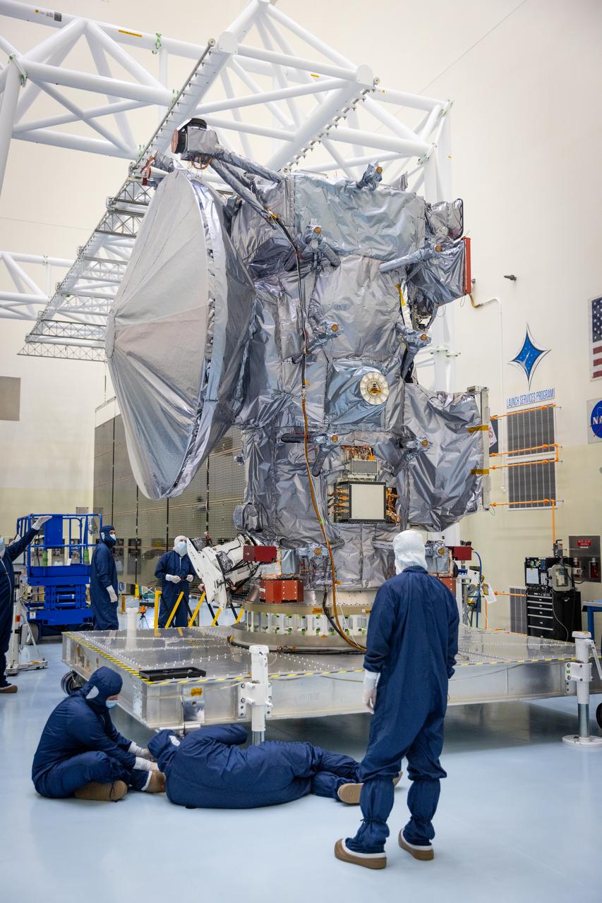
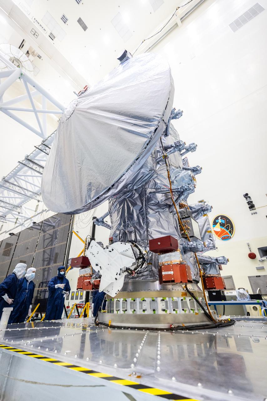
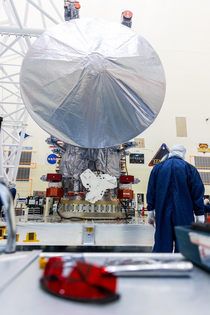
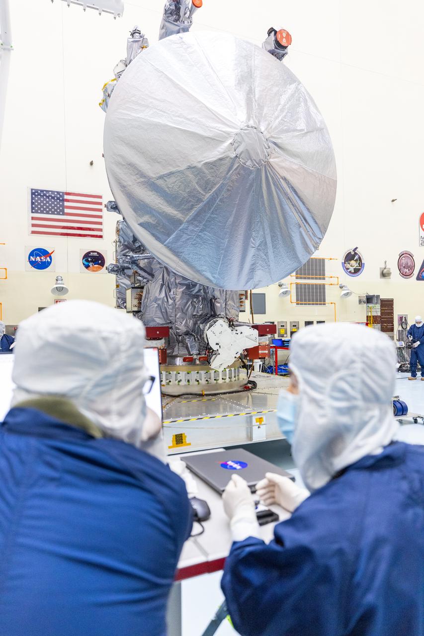
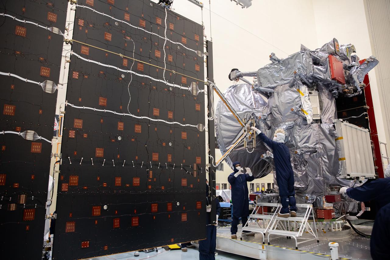
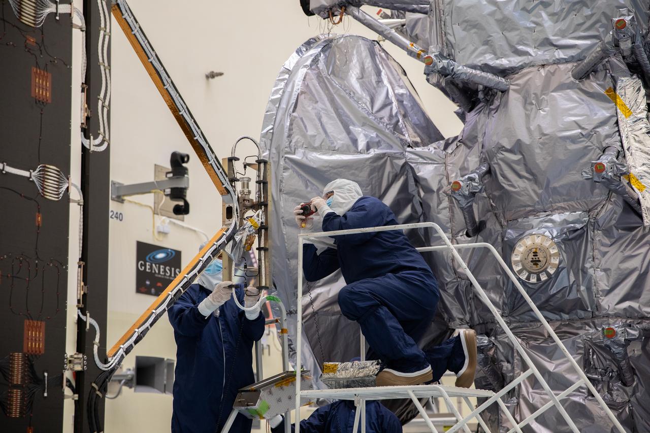
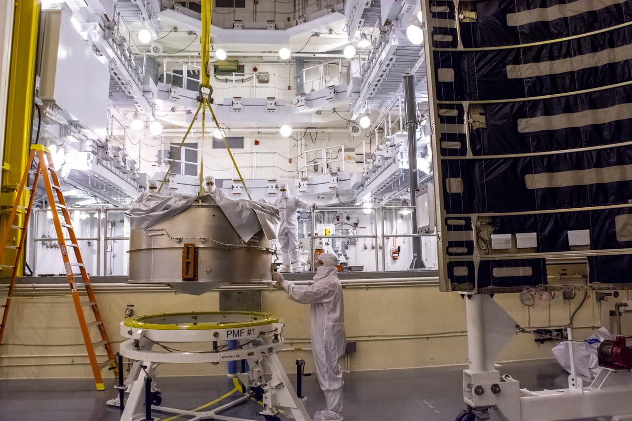
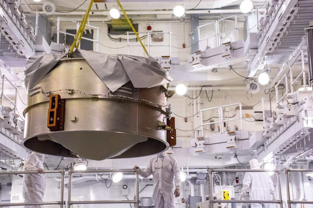
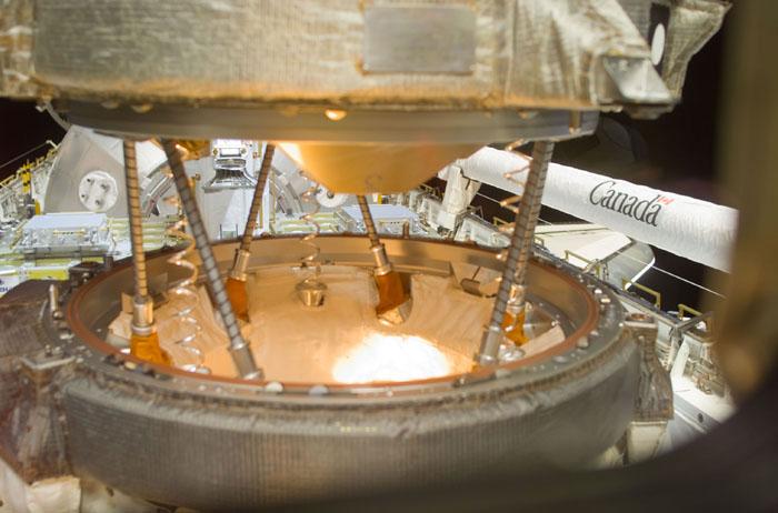
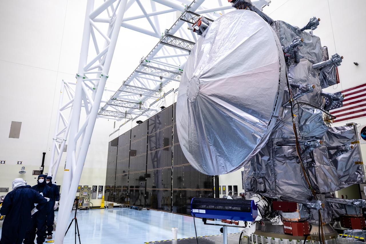
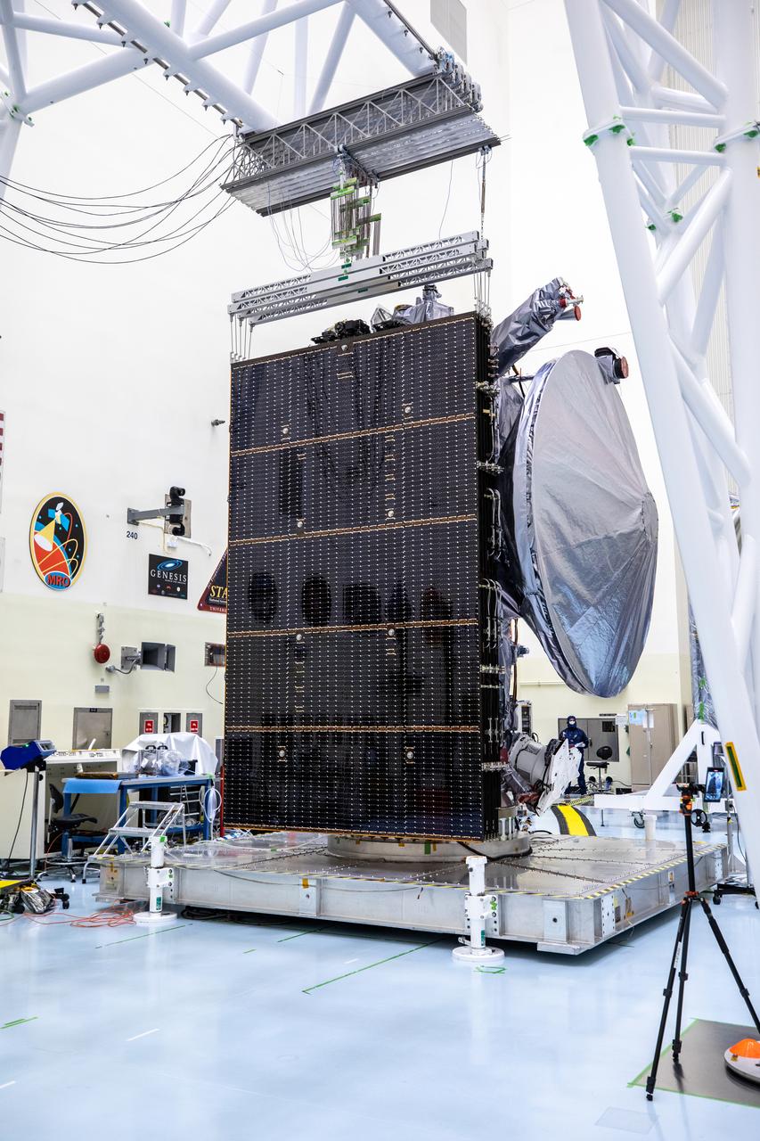
Technicians move NASA’s Europa Clipper spacecraft inside the Payload Hazardous Servicing Facility to accommodate installation of its five-panel solar array at the agency’s Kennedy Space Center in Florida on Thursday, Aug. 1, 2024. After moving the spacecraft, the team had to precisely align the spacecraft in preparation for the installation. The huge arrays – spanning more than 100 feet when fully deployed, or about the length of a basketball court – will collect sunlight to power the spacecraft as it flies multiple times around Jupiter’s icy moon, Europa, conducting science investigations to determine its potential to support life.
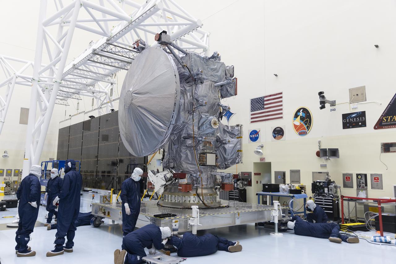
Technicians move NASA’s Europa Clipper spacecraft inside the Payload Hazardous Servicing Facility to accommodate installation of its five-panel solar array at the agency’s Kennedy Space Center in Florida on Thursday, Aug. 1, 2024. After moving the spacecraft, the team had to precisely align the spacecraft in preparation for the installation. The huge arrays – spanning more than 100 feet when fully deployed, or about the length of a basketball court – will collect sunlight to power the spacecraft as it flies multiple times around Jupiter’s icy moon, Europa, conducting science investigations to determine its potential to support life.
Technicians move NASA’s Europa Clipper spacecraft inside the Payload Hazardous Servicing Facility to accommodate installation of its five-panel solar array at the agency’s Kennedy Space Center in Florida on Thursday, Aug. 1, 2024. After moving the spacecraft, the team had to precisely align the spacecraft in preparation for the installation. The huge arrays – spanning more than 100 feet when fully deployed, or about the length of a basketball court – will collect sunlight to power the spacecraft as it flies multiple times around Jupiter’s icy moon, Europa, conducting science investigations to determine its potential to support life.
Technicians move NASA’s Europa Clipper spacecraft inside the Payload Hazardous Servicing Facility to accommodate installation of its five-panel solar array at the agency’s Kennedy Space Center in Florida on Thursday, Aug. 1, 2024. After moving the spacecraft, the team had to precisely align the spacecraft in preparation for the installation. The huge arrays – spanning more than 100 feet when fully deployed, or about the length of a basketball court – will collect sunlight to power the spacecraft as it flies multiple times around Jupiter’s icy moon, Europa, conducting science investigations to determine its potential to support life.
Technicians move NASA’s Europa Clipper spacecraft inside the Payload Hazardous Servicing Facility to accommodate installation of its five-panel solar array at the agency’s Kennedy Space Center in Florida on Thursday, Aug. 1, 2024. After moving the spacecraft, the team had to precisely align the spacecraft in preparation for the installation. The huge arrays – spanning more than 100 feet when fully deployed, or about the length of a basketball court – will collect sunlight to power the spacecraft as it flies multiple times around Jupiter’s icy moon, Europa, conducting science investigations to determine its potential to support life.
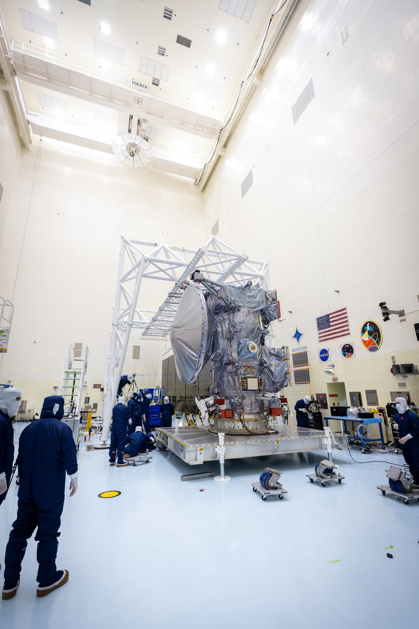
Technicians move NASA’s Europa Clipper spacecraft inside the Payload Hazardous Servicing Facility to accommodate installation of its five-panel solar array at the agency’s Kennedy Space Center in Florida on Thursday, Aug. 1, 2024. After moving the spacecraft, the team had to precisely align the spacecraft in preparation for the installation. The huge arrays – spanning more than 100 feet when fully deployed, or about the length of a basketball court – will collect sunlight to power the spacecraft as it flies multiple times around Jupiter’s icy moon, Europa, conducting science investigations to determine its potential to support life.
Technicians move NASA’s Europa Clipper spacecraft inside the Payload Hazardous Servicing Facility to accommodate installation of its five-panel solar array at the agency’s Kennedy Space Center in Florida on Thursday, Aug. 1, 2024. After moving the spacecraft, the team had to precisely align the spacecraft in preparation for the installation. The huge arrays – spanning more than 100 feet when fully deployed, or about the length of a basketball court – will collect sunlight to power the spacecraft as it flies multiple times around Jupiter’s icy moon, Europa, conducting science investigations to determine its potential to support life.
Technicians move NASA’s Europa Clipper spacecraft inside the Payload Hazardous Servicing Facility to accommodate installation of its five-panel solar array at the agency’s Kennedy Space Center in Florida on Thursday, Aug. 1, 2024. After moving the spacecraft, the team had to precisely align the spacecraft in preparation for the installation. The huge arrays – spanning more than 100 feet when fully deployed, or about the length of a basketball court – will collect sunlight to power the spacecraft as it flies multiple times around Jupiter’s icy moon, Europa, conducting science investigations to determine its potential to support life.
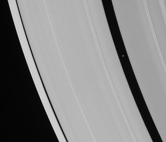
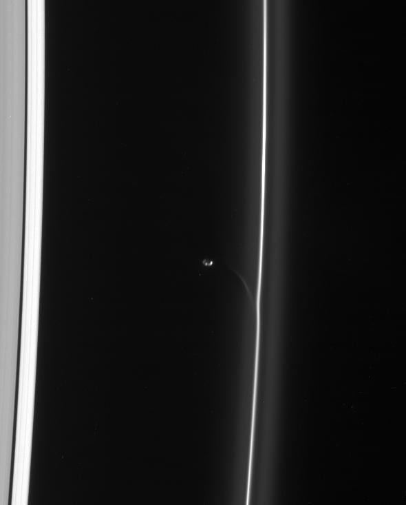
Saturn ring-embedded moons, Pan and Daphnis, are captured in an alignment they repeat with the regularity of a precise cosmic clock

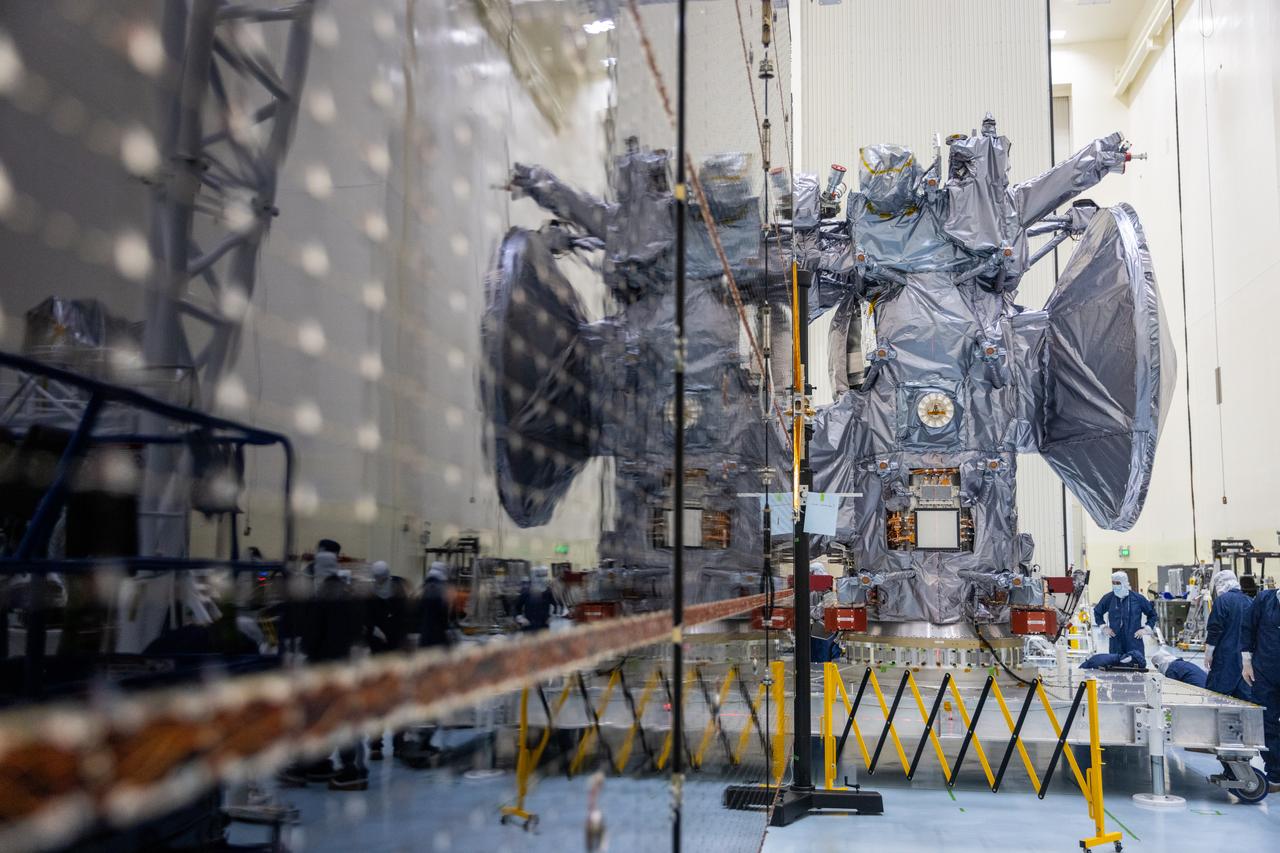
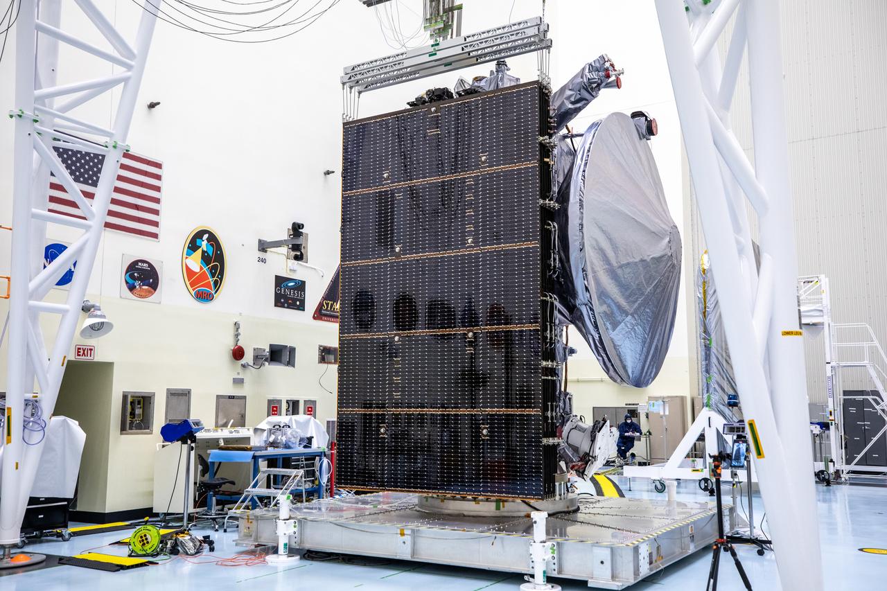
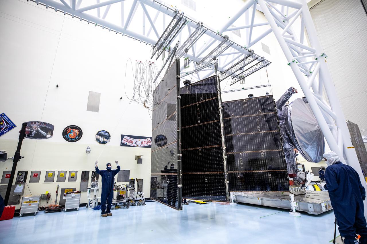
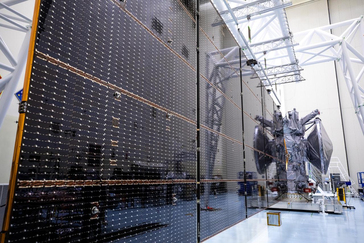
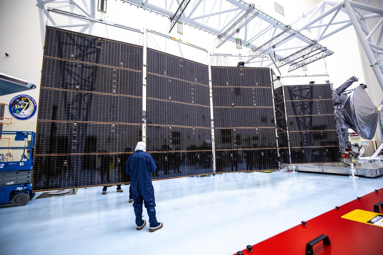
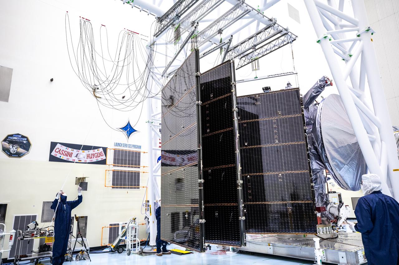
Technicians align, install, and then extend the second set of solar arrays, measuring 46.5 feet (14.2 meters) long and about 13.5 feet (4.1 meters) high, for NASA’s Europa Clipper spacecraft inside the agency’s Payload Hazardous Servicing Facility at Kennedy Space Center in Florida on Thursday, Aug. 15, 2024. The huge arrays – spanning more than 100 feet when fully deployed, or about the length of a basketball court – will collect sunlight to power the spacecraft as it flies multiple times around Jupiter’s icy moon, Europa, conducting science investigations to determine its potential to support life.
Technicians install and align the second set of solar arrays for NASA’s Europa Clipper spacecraft inside the agency’s Payload Hazardous Servicing Facility at Kennedy Space Center in Florida on Thursday, Aug. 15, 2024. The Europa Clipper spacecraft will need the 46.5 feet (14.2 meter) long, five-panel solar arrays on each side, to gather enough sunlight to power the spacecraft to perform flybys around Jupiter’s icy moon, Europa, so science instruments aboard the spacecraft can determine if the moon could hold the building blocks necessary to sustain life.
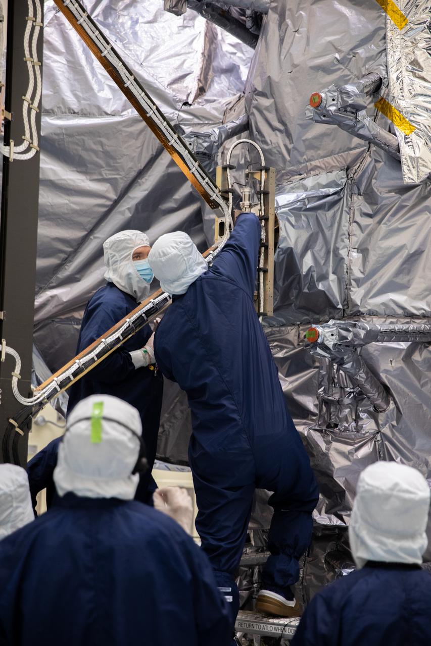
Technicians install and align the second set of solar arrays for NASA’s Europa Clipper spacecraft inside the agency’s Payload Hazardous Servicing Facility at Kennedy Space Center in Florida on Thursday, Aug. 15, 2024. The Europa Clipper spacecraft will need the 46.5 feet (14.2 meter) long, five-panel solar arrays on each side, to gather enough sunlight to power the spacecraft to perform flybys around Jupiter’s icy moon, Europa, so science instruments aboard the spacecraft can determine if the moon could hold the building blocks necessary to sustain life.
Technicians align, install, and then extend the second set of solar arrays, measuring 46.5 feet (14.2 meters) long and about 13.5 feet (4.1 meters) high, for NASA’s Europa Clipper spacecraft inside the agency’s Payload Hazardous Servicing Facility at Kennedy Space Center in Florida on Thursday, Aug. 15, 2024. The huge arrays – spanning more than 100 feet when fully deployed, or about the length of a basketball court – will collect sunlight to power the spacecraft as it flies multiple times around Jupiter’s icy moon, Europa, conducting science investigations to determine its potential to support life.

Technicians install and align the second set of solar arrays for NASA’s Europa Clipper spacecraft inside the agency’s Payload Hazardous Servicing Facility at Kennedy Space Center in Florida on Thursday, Aug. 15, 2024. The Europa Clipper spacecraft will need the 46.5 feet (14.2 meter) long, five-panel solar arrays on each side, to gather enough sunlight to power the spacecraft to perform flybys around Jupiter’s icy moon, Europa, so science instruments aboard the spacecraft can determine if the moon could hold the building blocks necessary to sustain life.
iss044e005118 (6/26/2015) --- Cosmonaut Gennady Padalka in the U.S. Laboratory in the process of aligning the Observation Analysis of Smectic Islands in Space (OASIS) Macro Camera. The Observation and Analysis of Smectic Islands In Space (OASIS) studies the unique behavior of liquid crystals in microgravity, including their overall motion and the merging of crystal layers known as smectic islands. Liquid crystals are used for display screens in televisions and clocks, and they also occur in soaps and in cell membranes. The experiment allows detailed studies of the behavior of these structures, and how microgravity affects their unique ability to act like both a liquid and a solid crystal.

Technicians install and align the second set of solar arrays for NASA’s Europa Clipper spacecraft inside the agency’s Payload Hazardous Servicing Facility at Kennedy Space Center in Florida on Thursday, Aug. 15, 2024. The Europa Clipper spacecraft will need the 46.5 feet (14.2 meter) long, five-panel solar arrays on each side, to gather enough sunlight to power the spacecraft to perform flybys around Jupiter’s icy moon, Europa, so science instruments aboard the spacecraft can determine if the moon could hold the building blocks necessary to sustain life.
Technicians install and align the second set of solar arrays for NASA’s Europa Clipper spacecraft inside the agency’s Payload Hazardous Servicing Facility at Kennedy Space Center in Florida on Thursday, Aug. 15, 2024. The Europa Clipper spacecraft will need the 46.5 feet (14.2 meter) long, five-panel solar arrays on each side, to gather enough sunlight to power the spacecraft to perform flybys around Jupiter’s icy moon, Europa, so science instruments aboard the spacecraft can determine if the moon could hold the building blocks necessary to sustain life.
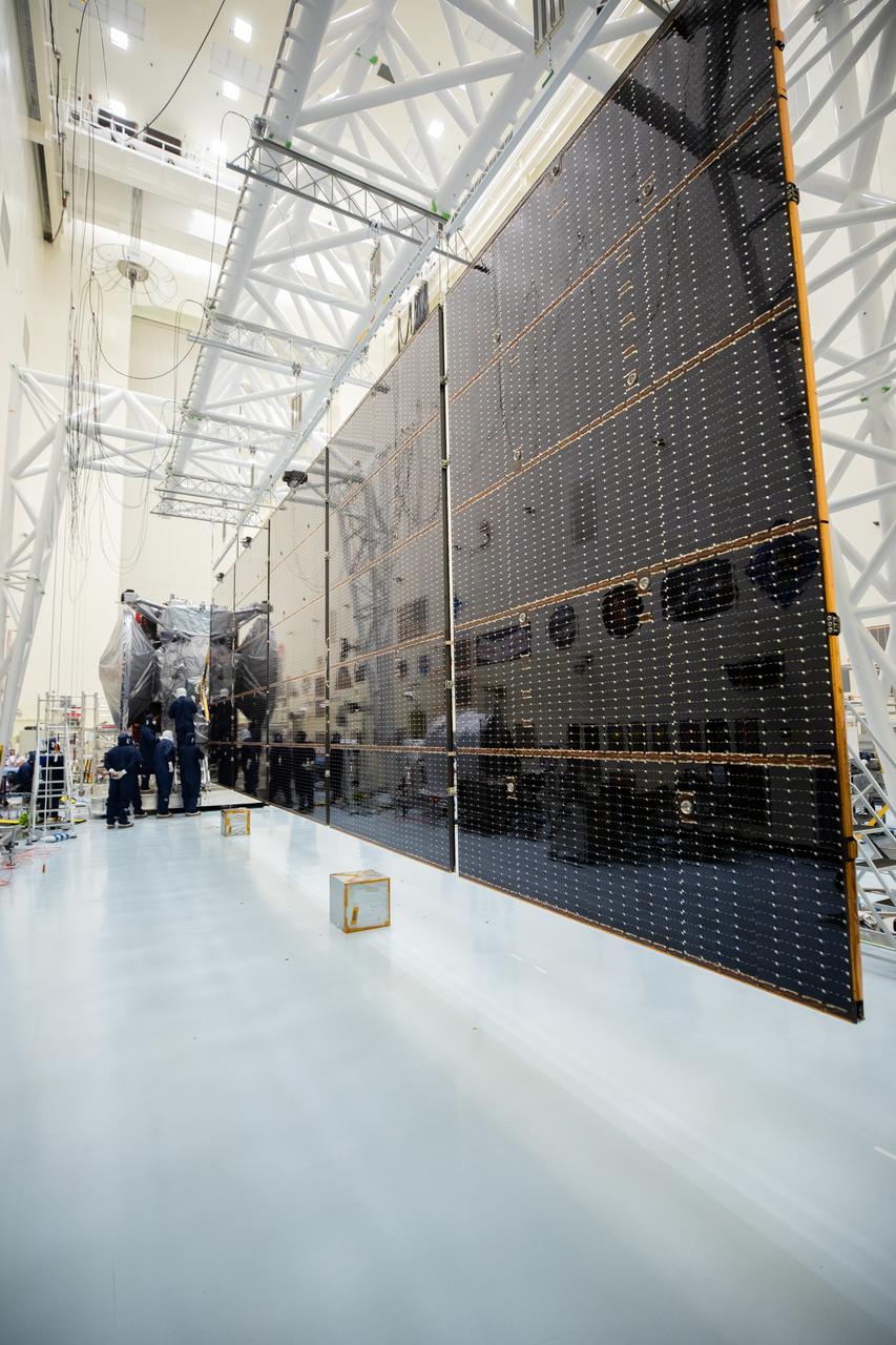
Technicians align, install, and then extend the second set of solar arrays, measuring 46.5 feet (14.2 meters) long and about 13.5 feet (4.1 meters) high, for NASA’s Europa Clipper spacecraft inside the agency’s Payload Hazardous Servicing Facility at Kennedy Space Center in Florida on Thursday, Aug. 15, 2024. The huge arrays – spanning more than 100 feet when fully deployed, or about the length of a basketball court – will collect sunlight to power the spacecraft as it flies multiple times around Jupiter’s icy moon, Europa, conducting science investigations to determine its potential to support life.

Technicians install and align the second set of solar arrays for NASA’s Europa Clipper spacecraft inside the agency’s Payload Hazardous Servicing Facility at Kennedy Space Center in Florida on Thursday, Aug. 15, 2024. The Europa Clipper spacecraft will need the 46.5 feet (14.2 meter) long, five-panel solar arrays on each side, to gather enough sunlight to power the spacecraft to perform flybys around Jupiter’s icy moon, Europa, so science instruments aboard the spacecraft can determine if the moon could hold the building blocks necessary to sustain life.
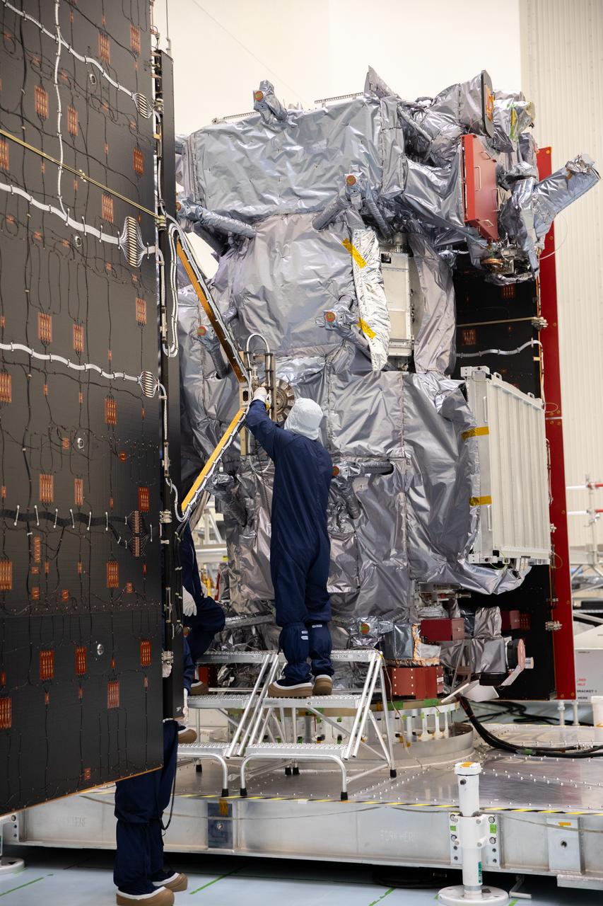
Technicians install and align the second set of solar arrays for NASA’s Europa Clipper spacecraft inside the agency’s Payload Hazardous Servicing Facility at Kennedy Space Center in Florida on Thursday, Aug. 15, 2024. The Europa Clipper spacecraft will need the 46.5 feet (14.2 meter) long, five-panel solar arrays on each side, to gather enough sunlight to power the spacecraft to perform flybys around Jupiter’s icy moon, Europa, so science instruments aboard the spacecraft can determine if the moon could hold the building blocks necessary to sustain life.

This fortunate view sights along Saturn ringplane to capture three moons aligned in a row: Dione at left, Prometheus at center and Epimetheus at right
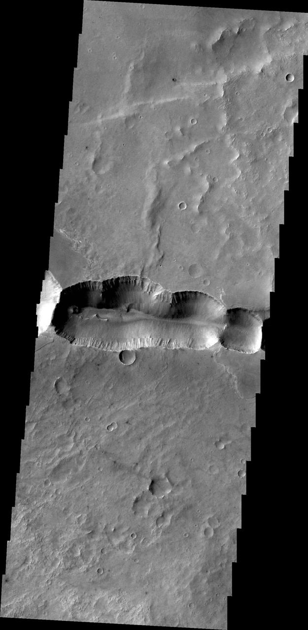
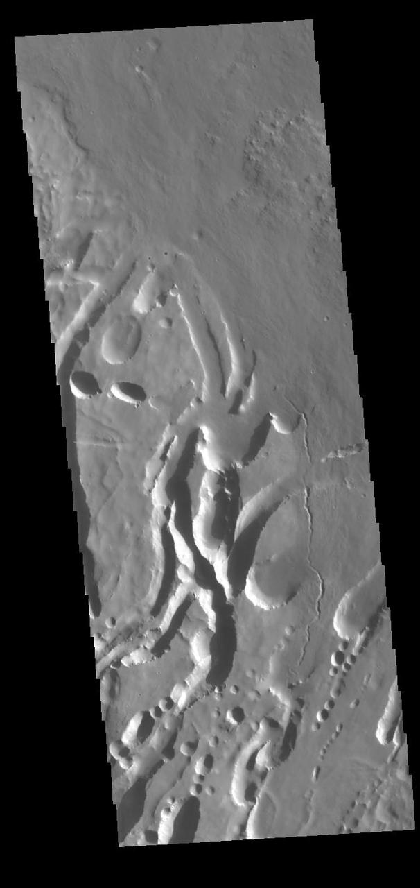
This image captured by NASA 2001 Mars Odyssey spacecraft shows a scallop-edged depression, called Coprates Catena, parallels the main alignment of Vallis Marineris.
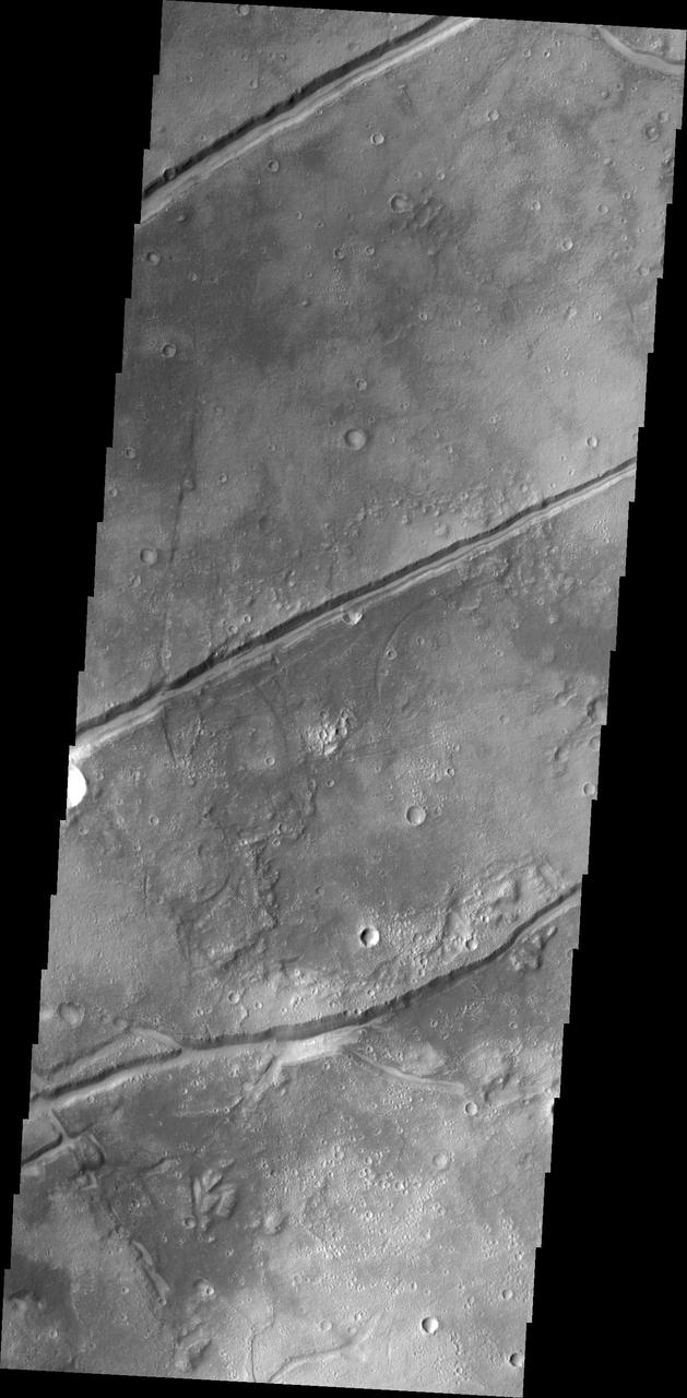
The fractures in this image captured by NASA 2001 Mars Odyssey spacecraft are aligned with most of the fractures in Tempe Terra, but are some distance from the bulk of the fracturing.
KENNEDY SPACE CENTER, FLA. - Workers in the Orbiter Processing Facility measure the alignment of bearings on a rudder speed brake actuator. Actuators move an orbiter’s rudder, speed brake, elevons and main engines during flight.
Inside the Integrated Processing Facility at Vandenberg Space Force Base in California, United Launch Alliance (ULA) technicians move the launch vehicle adapter for the ULA Atlas V rocket for NASA’s Landsat 9 satellite on June 22, 2021. Landsat 9 is scheduled to launch atop the Atlas V from Vandenberg in September 2021. The launch is being managed by NASA’s Launch Services Program based at Kennedy Space Center in Florida. Landsat 9 will continue the nearly 50-year legacy of previous Landsat missions. It will monitor key natural and economic resources from orbit. Landsat 9 is managed by the agency’s Goddard Space Flight Center in Greenbelt, Maryland. It will carry two instruments: the Operational Land Imager 2, which collects images of Earth’s landscapes in visible, near-infrared and shortwave infrared light, and the Thermal Infrared Sensor 2, which measures the temperature of land surfaces. Like its predecessors, Landsat 9 is a joint mission between NASA and the U.S. Geological Survey.
Inside the Integrated Processing Facility at Vandenberg Space Force Base in California, United Launch Alliance (ULA) technicians lift the launch vehicle adapter for the ULA Atlas V rocket for NASA’s Landsat 9 satellite on June 22, 2021. Landsat 9 is scheduled to launch atop the Atlas V from Vandenberg in September 2021. The launch is being managed by NASA’s Launch Services Program based at Kennedy Space Center in Florida. Landsat 9 will continue the nearly 50-year legacy of previous Landsat missions. It will monitor key natural and economic resources from orbit. Landsat 9 is managed by the agency’s Goddard Space Flight Center in Greenbelt, Maryland. It will carry two instruments: the Operational Land Imager 2, which collects images of Earth’s landscapes in visible, near-infrared and shortwave infrared light, and the Thermal Infrared Sensor 2, which measures the temperature of land surfaces. Like its predecessors, Landsat 9 is a joint mission between NASA and the U.S. Geological Survey.

This observation from NASA Mars Reconnaissance Orbiter shows what is called a calloped terrain, that appears here to merge in a linear depression.
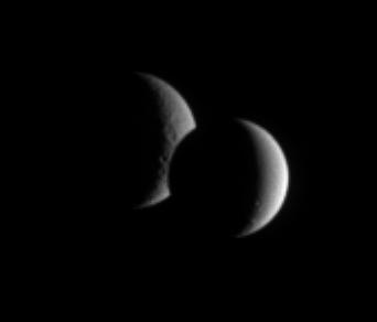
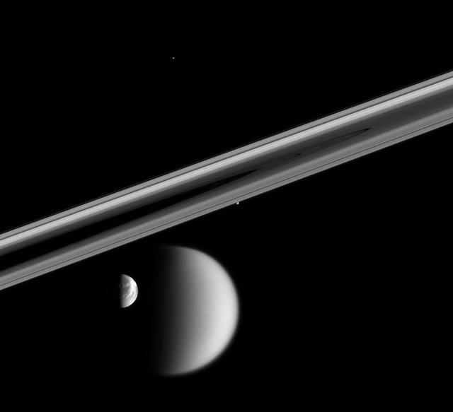
Dione and Rhea pair up for an occultation, or mutual event, as seen by Cassini. While the lit portion of each moon is but a crescent, the dark side of Dione has begun to take a bite out of its distant sibling moon
Today's VIS image shows the summit of Ascraeus Mons. Ascraeus Mons is the northernmost of the three aligned Tharsis volcanoes. Orbit Number: 80602 Latitude: 11.189 Longitude: 255.887 Instrument: VIS Captured: 2020-02-15 02:07 https://photojournal.jpl.nasa.gov/catalog/PIA23841

This image from NASA Mars Odyssey shows part of the eastern flank of Ascraeus Mons, one of the large Tharsis Volcanoes. The circular pits all aligned in a row mark the collapse of the roof of a lava tube.
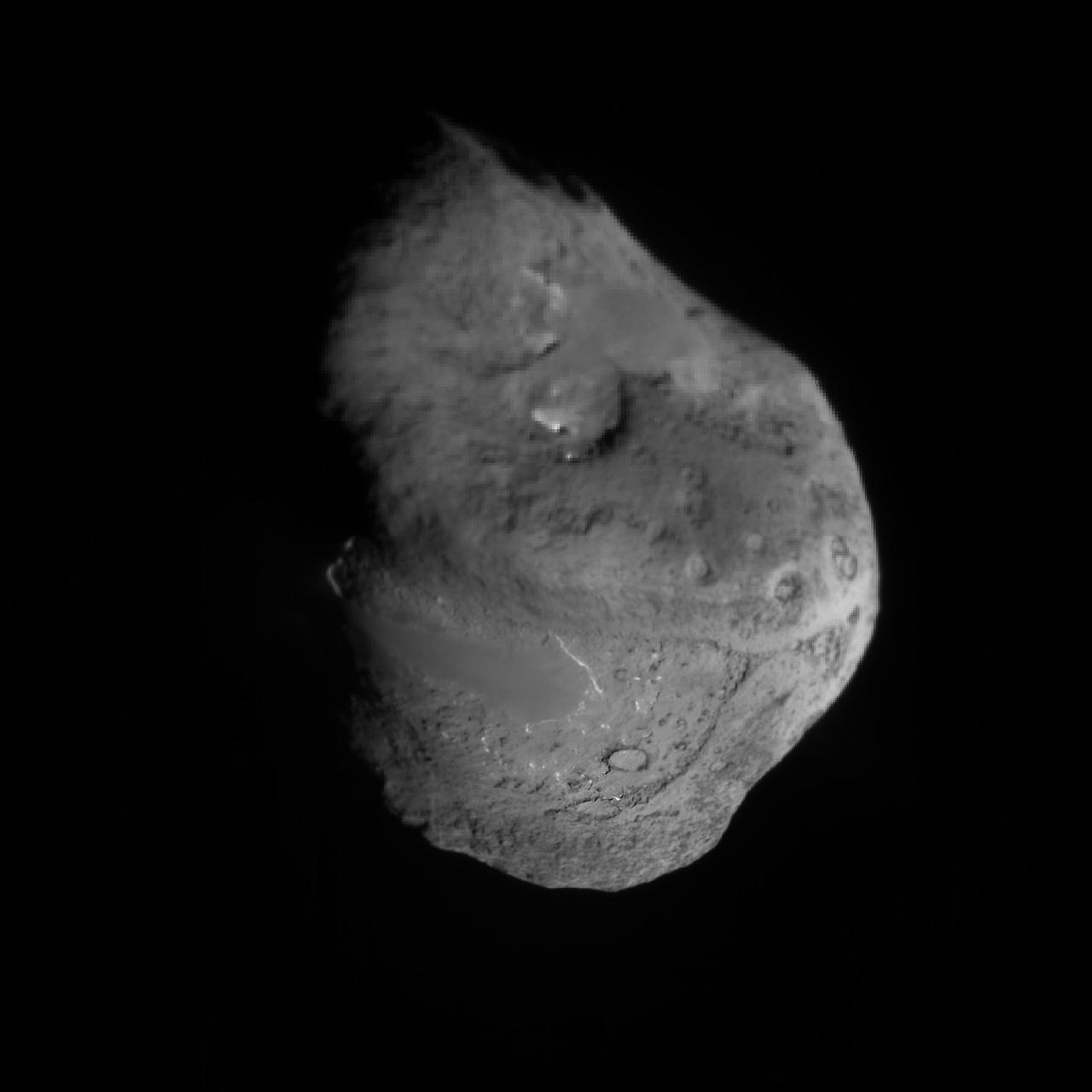
This Tempel 1 image was built up from scaling images from NASA Deep Impact to 5 meters/pixel and aligned to fixed points. Each image at closer range replaced equivalent locations observed at a greater distance.
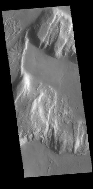
Arsia Chasmata is a complex collapsed region at the northeastern flank of Arsia Mons. The collapsed region aligns with the Pavonis and Ascraeus Mons volcanoes, indicating that all three volcanoes are located on a major fracture in the Tharsis region.
Prometheus draws a fresh streamer of material from the F ring as it passes the ring interior edge. The streamer will continuously shear out as it orbits the planet, becoming more elongated and increasingly aligned with the F ring with time
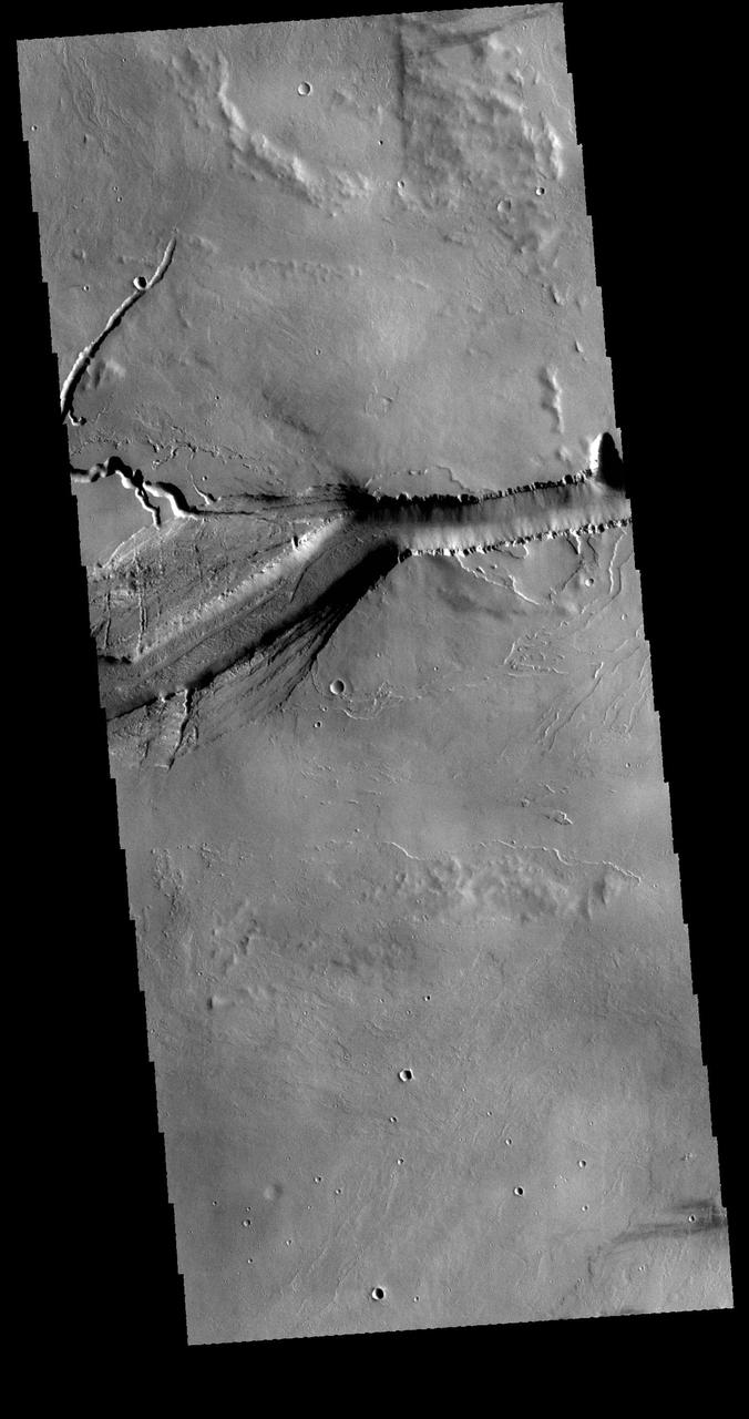
This image from NASA 2001 Mars Odyssey spacecraft shows Pavonis Chasma, a collapsed region on the northeastern flank of Pavonis Mons. The chasma is aligned with the trend of the three Tharsis volcanoes, of which Pavonis Mons is the central one.
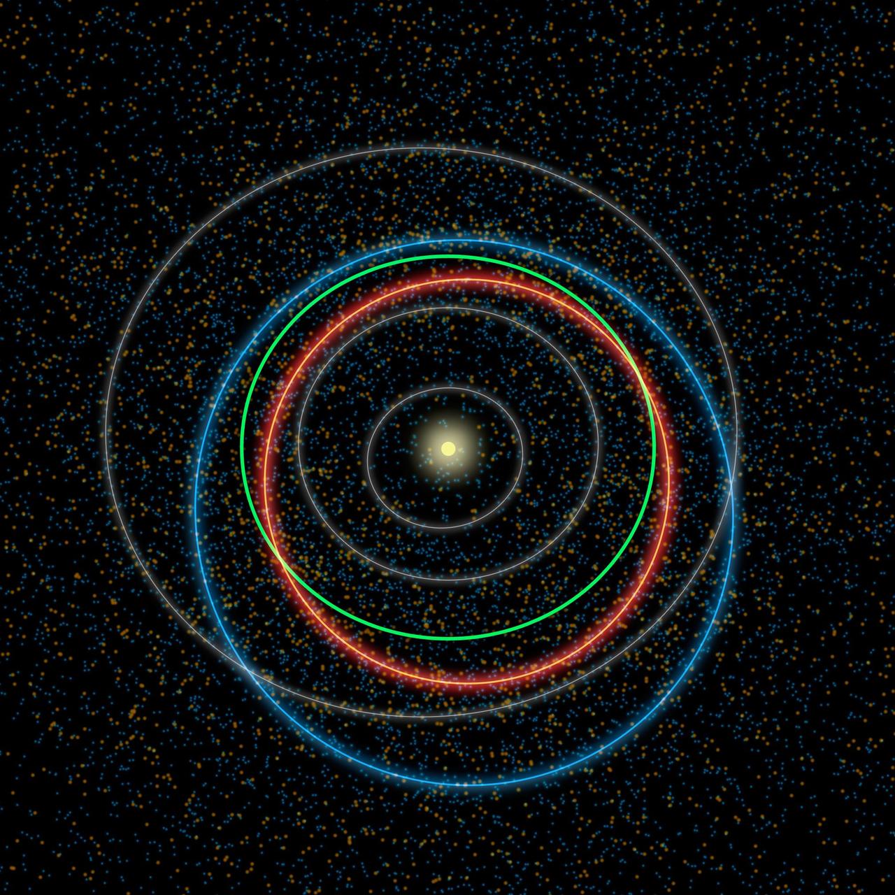
Results from NASA NEOWISE survey find that more potentially hazardous asteroids, or PHAs, are closely aligned with the plane of our solar system than previous models suggested.
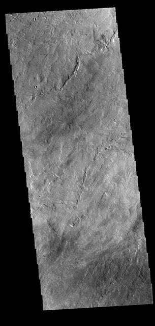
This VIS image shows part of Medusa Fossae. Winds have eroded materials in this region, creating ridges and valleys aligned with the direction of the wind. Orbit Number: 72008 Latitude: -3.47752 Longitude: 199.295 Instrument: VIS Captured: 2018-03-09 07:31 https://photojournal.jpl.nasa.gov/catalog/PIA22510

A NASA F/A-18 is towed to the apron at NASA's Armstrong Flight Research Center in Edwards, California during sunrise over Rogers Dry Lake. The F/A-18 was used to test a transmitter for an air navigation system, called the Airborne Location Integrating Geospatial Navigation System, or ALIGNS. This system, designed to allow pilots to position their aircraft at precise distances to each other, will be critical for acoustic validation efforts of NASA's next supersonic X-plane, the X-59 Quiet SuperSonic Technology.
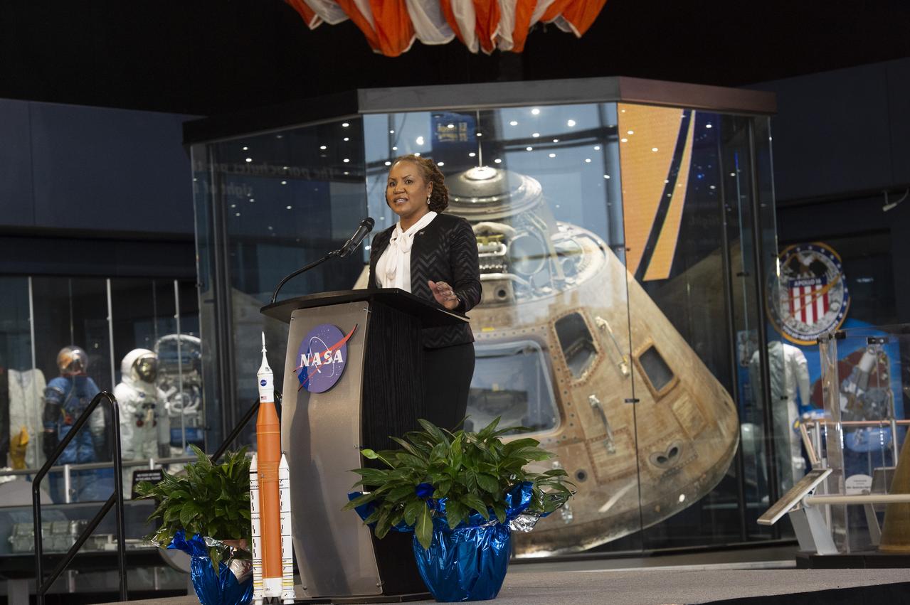
Monica Manning, assistant administrator of NASA’s Office of Procurement, addresses a crowd of nearly 900 industry leaders from 33 states at the 29th Marshall Small Business Alliance meeting Feb. 20 at the U.S. Space & Rocket Center. Manning introduced a new model for managing mission support for the agency, with the intent to align and simplify processes.
KENNEDY SPACE CENTER, FLA. - Workers in the Orbiter Processing Facility settle into place one of two rudder speed brake actuators onto a table to measure the alignment of its bearings. The actuators move an orbiter’s rudder, speed brake, elevons and main engines during flight.
KENNEDY SPACE CENTER, FLA. - Workers in the Orbiter Processing Facility get ready to measure the alignment of the bearings on the rudder speed brake actuators sitting on the floor in the foreground. The actuators move an orbiter’s rudder, speed brake, elevons and main engines during flight.
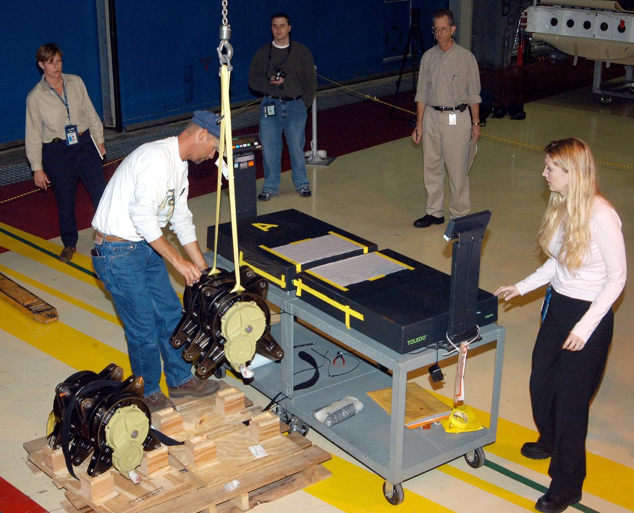
KENNEDY SPACE CENTER, FLA. - Workers in the Orbiter Processing Facility stand by while another guides the lifting of one of two rudder speed brake actuators onto a table to measure the alignment of its bearings. The actuators move an orbiter’s rudder, speed brake, elevons and main engines during flight.
Today's VIS image shows the eastern flank of Arsia Mons, the southernmost aligned volcano in the Tharsis region. The volcano is 435 kilometres (270 mi) in diameter, and almost 20 kilometres (12 mi) high. Arsia Mons is one of the youngest volcanoes on Mars. Orbit Number: 80952 Latitude: -9.8557 Longitude: 241.487 Instrument: VIS Captured: 2020-03-14 21:40 https://photojournal.jpl.nasa.gov/catalog/PIA23931
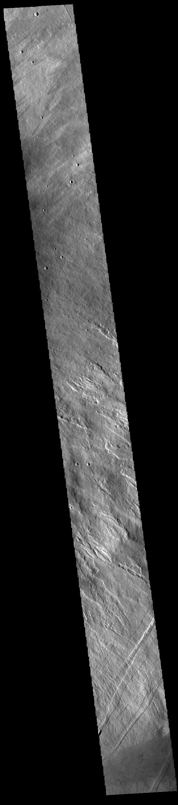
This image from NASA 2001 Mars Odyssey spacecraft shows the northern margin of Tanaica Montes. These hills are cut by fractures, which are in alignment with the regional trend of tectonic faulting found east of Alba Mons. Orbit Number: 61129 Latitude: 40.1468 Longitude: 269.641 Instrument: VIS Captured: 2015-09-25 03:03
This image from NASA 2001 Mars Odyssey spacecraft shows a different portion of Olympica Fossae from yesterday image. The east/west alignment is a very uniform width, in this region the fracturing widens as the feature makes a turn to the south. http://photojournal.jpl.nasa.gov/catalog/PIA20114
The three large aligned Tharsis volcanoes are Arsia Mons, Pavonis Mons and Ascreaus Mons (from south to north). There are collapse features on all three volcanoes, on the southwestern and northeastern flanks. This alignment may indicate a large fracture/vent system was responsible for the eruptions that formed all three volcanoes. This VIS image shows part of the southern flank of Arsia Mons, along the center of the aligned fracture system. The scalloped depressions are most likely created by collapse of the roof of lava tubes. Lava tubes originate during eruption event, when the margins of a flow harden around a still flowing lava stream. When an eruption ends these can become hollow tubes within the flow. With time, the roof of the tube may collapse into the empty space below. The tubes are linear, so the collapse of the roof creates a linear depression. In this region, the complexity of the collapse and faulting has created a unique surface. This region has collapse depressions with floors at a variety of elevations and depression sizes from small to large. Arsia Mons is the southernmost of the Tharsis volcanoes. It is 270 miles (450km) in diameter, almost 12 miles (20km) high, and the summit caldera is 72 miles (120km) wide. For comparison, the largest volcano on Earth is Mauna Loa. From its base on the sea floor, Mauna Loa measures only 6.3 miles high and 75 miles in diameter. A large volcanic crater known as a caldera is located at the summit of all of the Tharsis volcanoes. These calderas are produced by massive volcanic explosions and collapse. The Arsia Mons summit caldera is larger than many volcanoes on Earth. Orbit Number: 88040 Latitude: -6.88266 Longitude: 240.595 Instrument: VIS Captured: 2021-10-19 12:23 https://photojournal.jpl.nasa.gov/catalog/PIA25116
ROBERT CARROLL, A MACHINIST WITH LOCKHEED MARTIN, DRILLS ALIGNMENT HOLES ON THE EXTERNAL TANK COMPOSITE NOSE CONE
These images taken by NASA's Stardust spacecraft highlight the diverse features that make up the surface of comet Wild 2, showing a variety of small pinnacles and mesas seen on the limb of the comet and the location of a 2-kilometer (1.2-mile) series of aligned scarps, or cliffs, that are best seen in the stereo images. http://photojournal.jpl.nasa.gov/catalog/PIA06284

Lockheed Martin technicians work to align and check the fastener holes on the X-59’s fuselage skin. The aircraft, under construction at Lockheed Martin Skunk Works in Palmdale, California, will demonstrate the ability to fly supersonic while reducing the loud sonic boom to a quiet sonic thump.
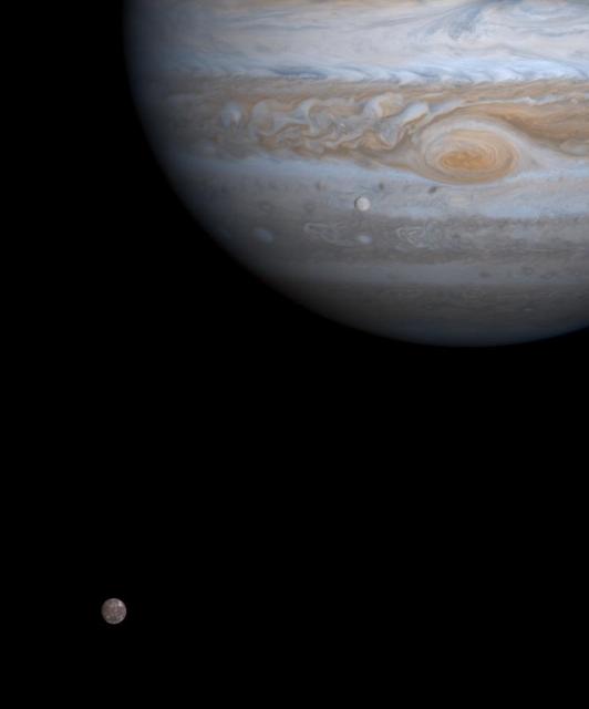
One moment in an ancient, orbital dance is caught in this color picture taken by NASA Cassini spacecraft on Dec. 7, 2000, just as two of Jupiter four major moons, Europa and Callisto, were nearly perfectly aligned with each other.
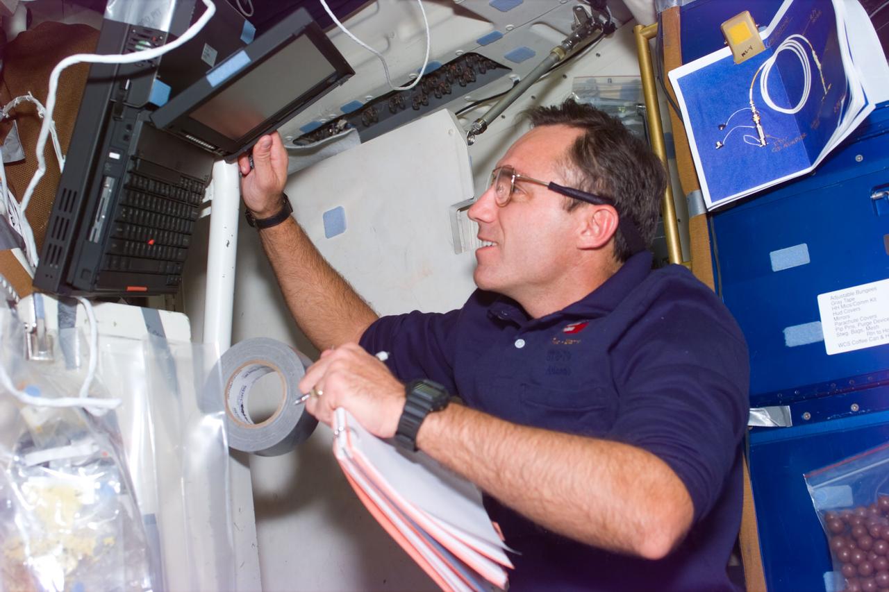
STS79-E-5024 (18 September 1996) --- Carl E. Walz, mission specialist, aligns computer to assist in an experiment in Spacehab Module, on Flight Day 3.
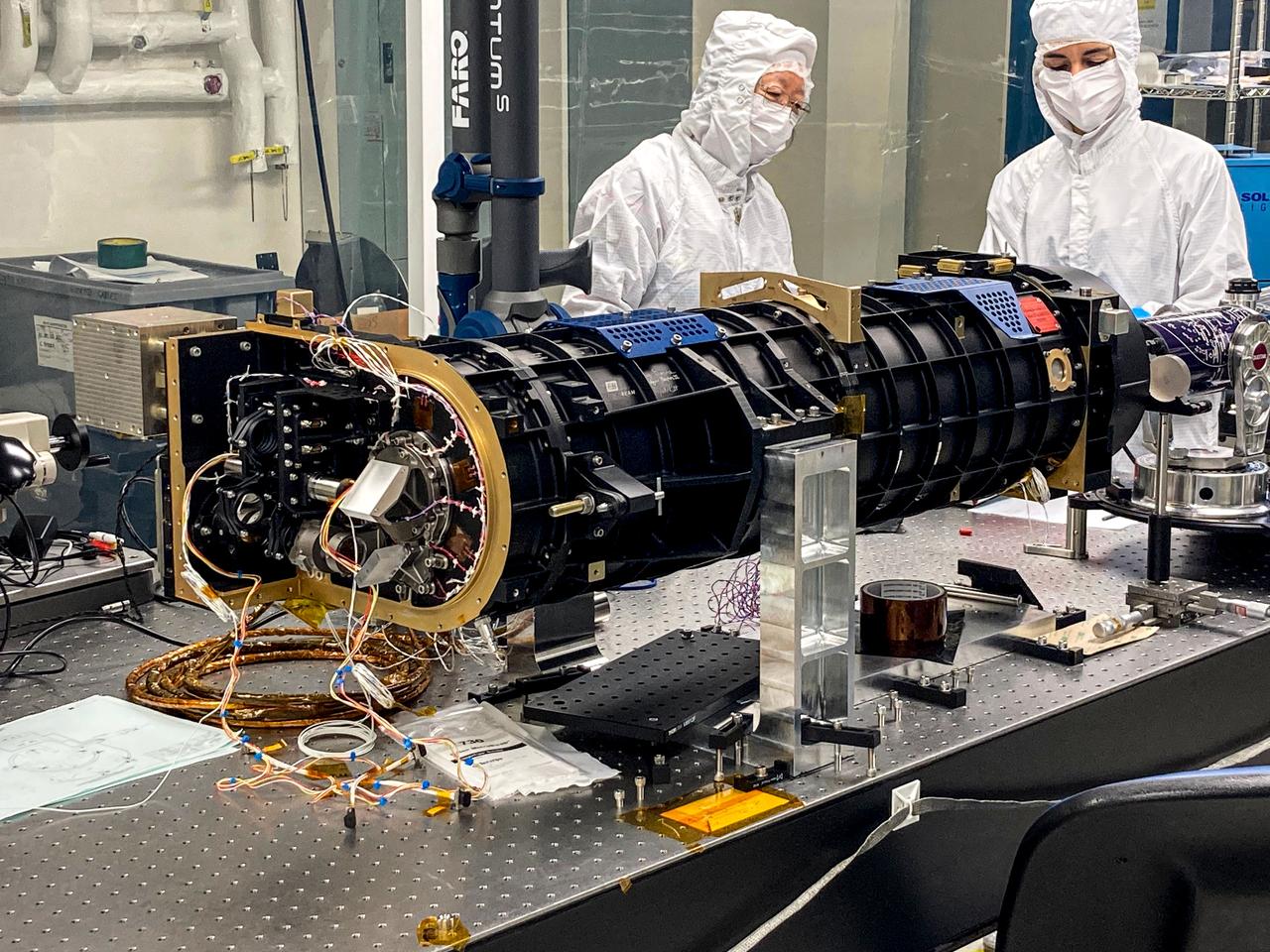
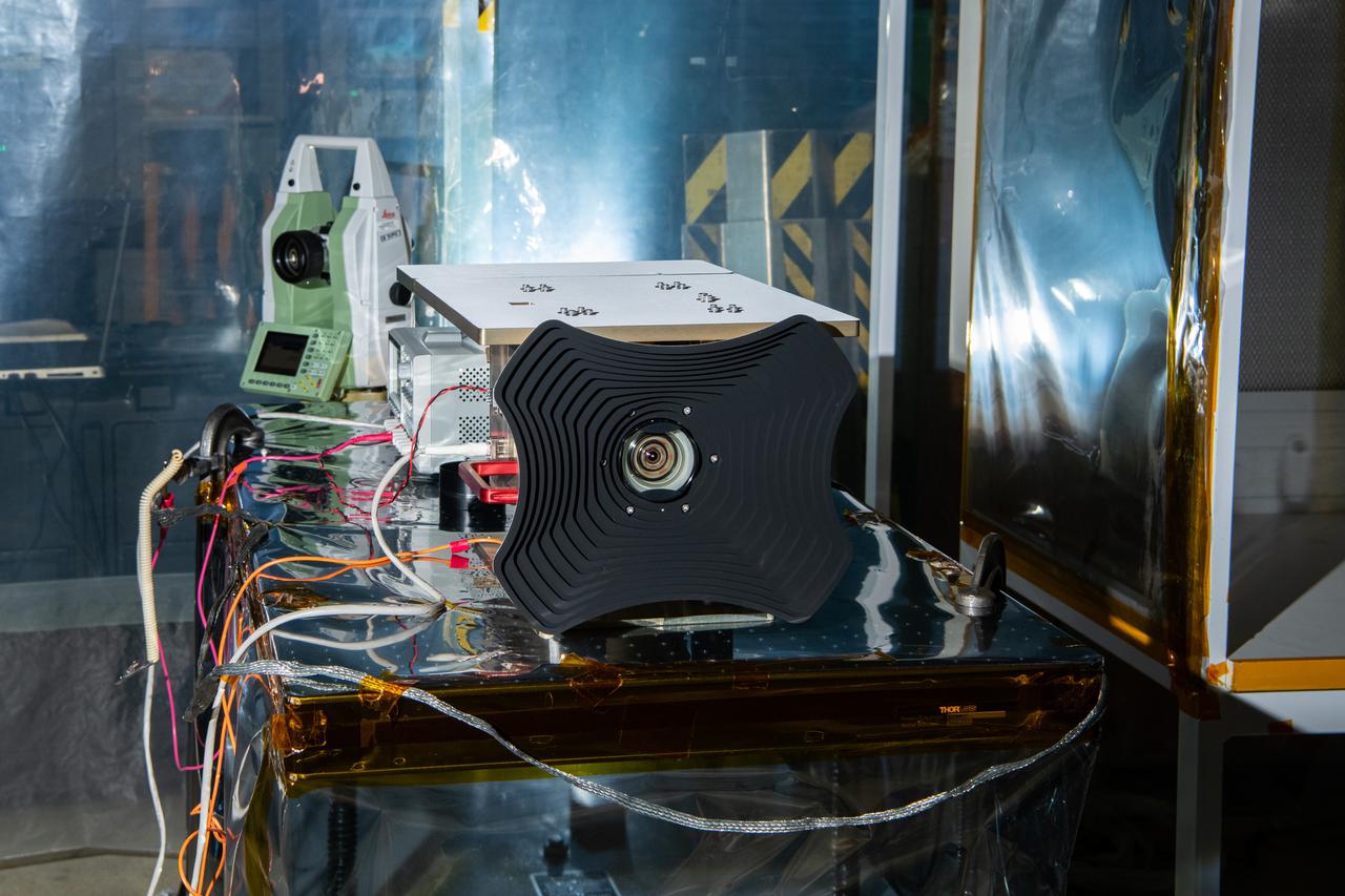
jsc2024e061950 (9/12/2024) --- The COronal Diagnostic EXperiment (CODEX) coronagraph during optical alignment and assembly. Credit: CODEX team / NASA

This VIS image shows a small portion of the lava flows that comprise Daedalia Planum. The flows originated at Arsia Mons, the youngest of the three Tharsis volcanoes. The Tharsis volcanoes are aligned in a northeast trending system. The majority of the Daedalia Planum flows can be traced back to the southern flank of Arsia Mons along the extension of the controlling alignment. Orbit Number: 71932 Latitude: -24.5979 Longitude: 235.782 Instrument: VIS Captured: 2018-03-03 01:09 https://photojournal.jpl.nasa.gov/catalog/PIA22408

This VIS image shows a small portion of the lava flows that comprise Daedalia Planum. The flows originated at Arsia Mons, the youngest of the three Tharsis volcanoes. The Tharsis volcanoes are aligned in a northeast trending system. The majority of the Daedalia Planum flows can be traced back to the southern flank of Arsia Mons along the extension of the controlling alignment. Orbit Number: 71932 Latitude: -24.5979 Longitude: 235.782 Instrument: VIS Captured: 2018-03-03 01:09 https://photojournal.jpl.nasa.gov/catalog/PIA22409

Two NASA F-15 aircraft sit on the ramp at NASA's Armstrong Flight Research Center, in Edwards, California, ahead of dual F-15 flights that validated the integration of three tools – the Airborne Schlieren Photography System (ASPS), the Airborne Location Integrating Geospatial Navigation System (ALIGNS), and shock-sensing probe. Together these tools will measure and visualize the shock waves generated by NASA's X-59.
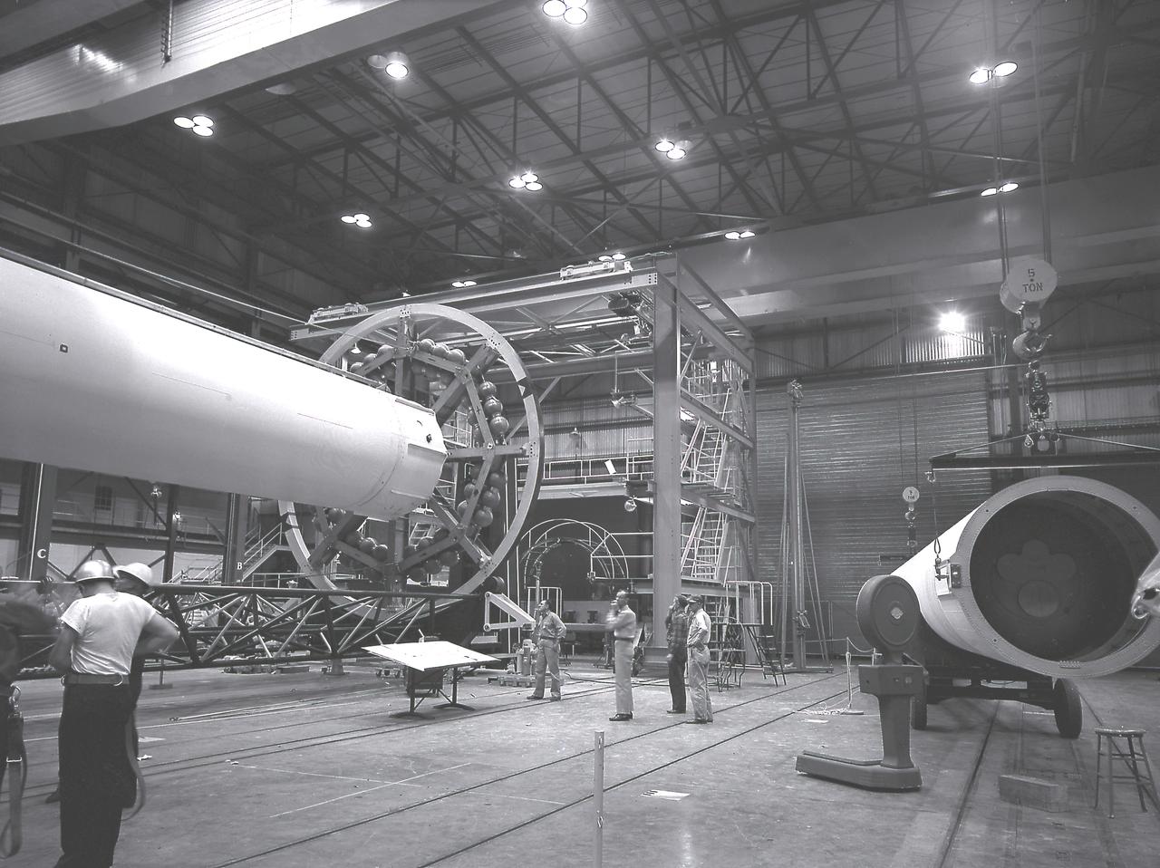
The Saturn I liquid-oxygen (LOX) tank for the Saturn I S-I stage being aligned with the end spider beam in the fabrication and engineering laboratory, building 4705, at the Marshall Space Flight Center (MSFC).
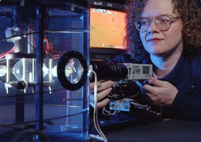
Jeri Briscoe of the video team inspects the optical system for proper alignment during a test run of the Equiaxed Dendritic Solidification Experiment (EDSE) located in the Microgravity Development Laboratory (MDL).
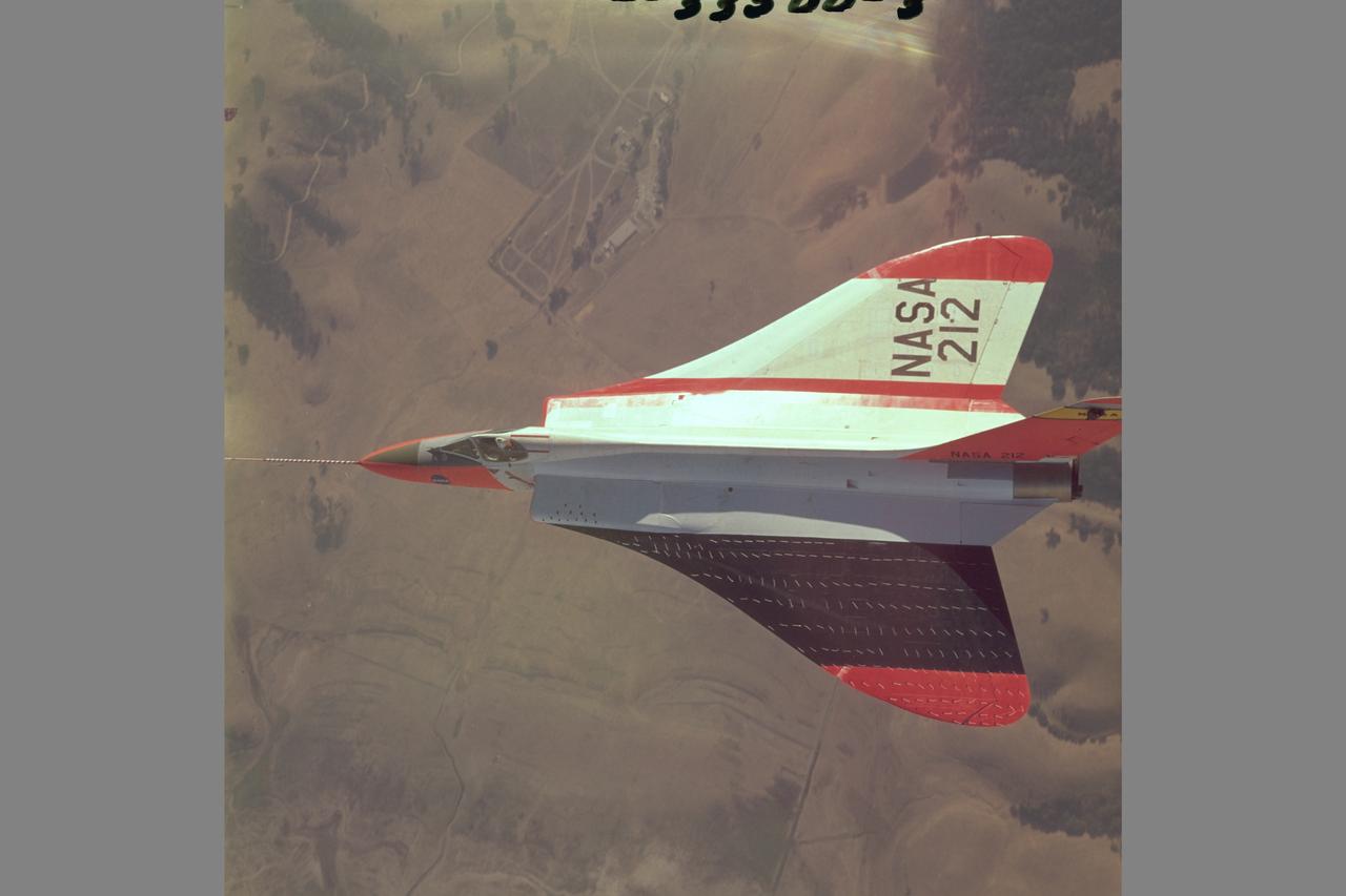
Douglas F5D Skylancer fighter modified with ogee wing planform designed for Mach 2 flight. Shown is the effect of vortex flow on wing tuft alignment in low-speed, high angle-of-attack flight.

Southwest Research Institute astronomer Dan Durda checks the alignment of the SWUIS-A Xybion digital camera mounted in the rear cockpit of a NASA Dryden F/A-18B before taking off on an astronomy mission.
This VIS image shows part of Medusa Fossae. Winds have eroded materials in this region, creating ridges and valleys aligned with the direction of the wind. These features are created by long term winds scouring a poorly cemented surface material. It has been suggested that this region of Mars provides a large percentage of the surface dust seen around the planet. Ash falls from nearby volcanoes may have been the source of the surface materials eroded into these and other wind eroded landforms. Orbit Number: 79144 Latitude: -4.5831 Longitude: 200.487 Instrument: VIS Captured: 2019-10-18 00:48 https://photojournal.jpl.nasa.gov/catalog/PIA23576
This VIS image is located on the eastern flank of Alba Mons. Linear faults and graben surround the volcano aligned north/south, intersecting and deflected around the summit. The large graben is called Phlegethon Catena. The term catena means a string of craters or circular depressions. The depressions in this image were likely formed by the collapse of the preexisting surface into a subsurface void. Graben are caused by blocks of material that drop down along paired faults. Orbit Number: 72405 Latitude: 36.2522 Longitude: 255.129 Instrument: VIS Captured: 2018-04-11 00:39 https://photojournal.jpl.nasa.gov/catalog/PIA22596
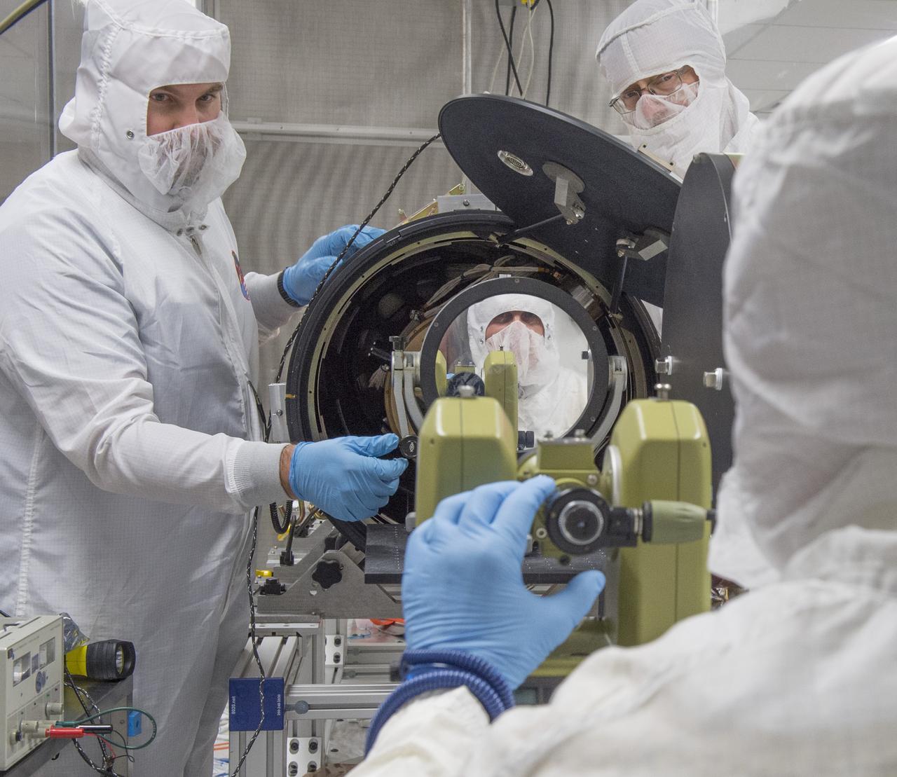
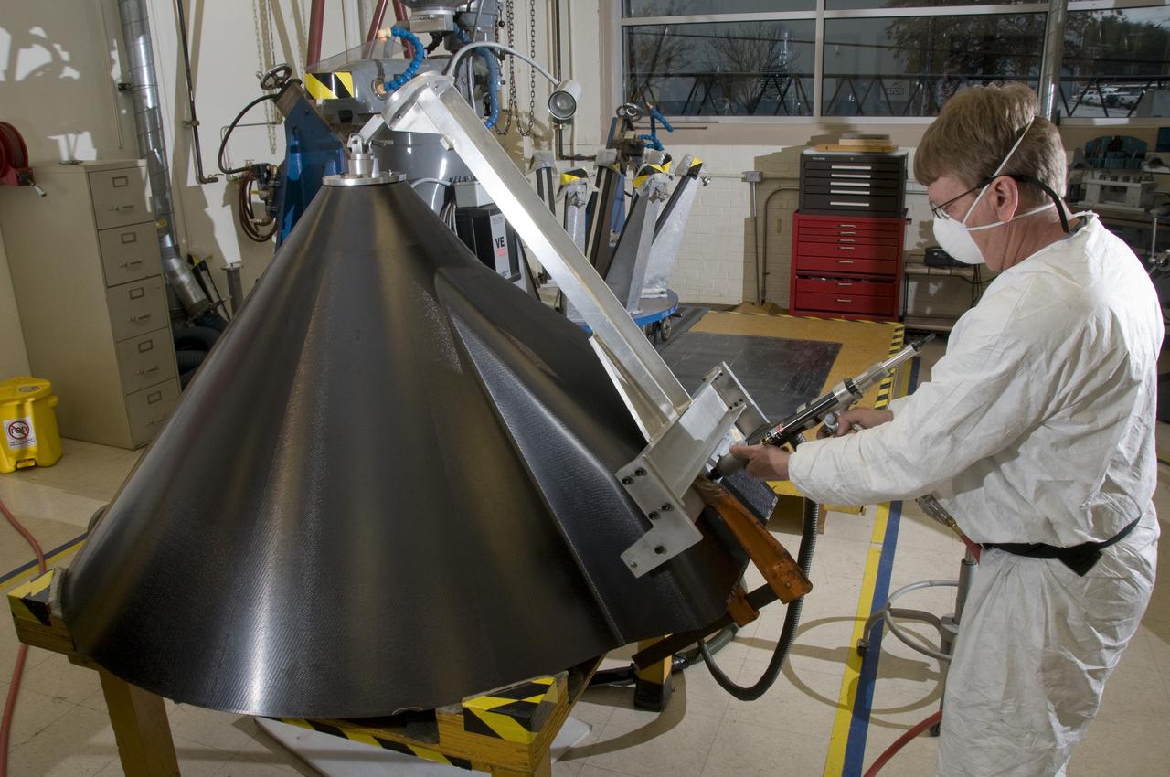
The Shooting Star Experiment (SSE) is designed to develop and demonstrate the technology required to focus the sun's energy and use the energy for inexpensive space Propulsion Research. Pictured is an engineering model (Pathfinder III) of the Shooting Star Experiment (SSE). This model was used to test and characterize the motion and deformation of the structure caused by thermal effects. In this photograph, alignment targets are being placed on the engineering model so that a theodolite (alignment telescope) could be used to accurately measure the deformation and deflections of the engineering model under extreme conditions, such as the coldness of deep space and the hotness of the sun as well as vacuum. This thermal vacuum test was performed at the X-Ray Calibration Facility because of the size of the test article and the capabilities of the facility to simulate in-orbit conditions
Scientists at Marshall's Adaptive Optics Lab demonstrate the Wave Front Sensor alignment using the Phased Array Mirror Extendible Large Aperture (PAMELA) optics adjustment. The primary objective of the PAMELA project is to develop methods for aligning and controlling adaptive optics segmented mirror systems. These systems can be used to acquire or project light energy. The Next Generation Space Telescope is an example of an energy acquisition system that will employ segmented mirrors. Light projection systems can also be used for power beaming and orbital debris removal. All segmented optical systems must be adjusted to provide maximum performance. PAMELA is an on going project that NASA is utilizing to investigate various methods for maximizing system performance.
![The linear features in the bottom half of this VIS image are called Oti Fossae. Oti Fossae is located on the eastern flank of Arsia Mons and aligns with the regional northeast/southwest trend of the major Tharsis volcanoes. Fossae are typically tectonic features termed graben. Graben are formed by extension of the crust and faulting. When large amounts of pressure or tension are applied to rocks on timescales that are fast enough that the rock cannot respond by deforming, the rock breaks along faults. In the case of a graben, two parallel faults are formed by extension of the crust and the rock in between the faults drops downward into the space created by the extension. The crustal deformation in this region was from the inflation of the surface by the rise of magma that created the Tharsis volcanoes. Arsia Mons is the southernmost and youngest of the three large, aligned Tharsis volcanoes [Arsia Mons, Pavonis Mons and Ascreaus Mons, from south to north]. This alignment may indicate a large fracture/vent system was responsible for the eruptions that formed all three volcanoes. Arsia Mons is 270 miles (450km) in diameter, almost 12 miles (20km) high, and the summit caldera is 72 miles (120km) wide. For comparison, the largest volcano on Earth is Mauna Loa. From its base on the sea floor, Mauna Loa measures only 6.3 miles high and 75 miles in diameter. Orbit Number: 94978 Latitude: -8.70852 Longitude: 242.873 Instrument: VIS Captured: 2023-05-13 18:56 https://photojournal.jpl.nasa.gov/catalog/PIA26224](https://images-assets.nasa.gov/image/PIA26224/PIA26224~medium.jpg)
The linear features in the bottom half of this VIS image are called Oti Fossae. Oti Fossae is located on the eastern flank of Arsia Mons and aligns with the regional northeast/southwest trend of the major Tharsis volcanoes. Fossae are typically tectonic features termed graben. Graben are formed by extension of the crust and faulting. When large amounts of pressure or tension are applied to rocks on timescales that are fast enough that the rock cannot respond by deforming, the rock breaks along faults. In the case of a graben, two parallel faults are formed by extension of the crust and the rock in between the faults drops downward into the space created by the extension. The crustal deformation in this region was from the inflation of the surface by the rise of magma that created the Tharsis volcanoes. Arsia Mons is the southernmost and youngest of the three large, aligned Tharsis volcanoes [Arsia Mons, Pavonis Mons and Ascreaus Mons, from south to north]. This alignment may indicate a large fracture/vent system was responsible for the eruptions that formed all three volcanoes. Arsia Mons is 270 miles (450km) in diameter, almost 12 miles (20km) high, and the summit caldera is 72 miles (120km) wide. For comparison, the largest volcano on Earth is Mauna Loa. From its base on the sea floor, Mauna Loa measures only 6.3 miles high and 75 miles in diameter. Orbit Number: 94978 Latitude: -8.70852 Longitude: 242.873 Instrument: VIS Captured: 2023-05-13 18:56 https://photojournal.jpl.nasa.gov/catalog/PIA26224
The three large aligned Tharsis volcanoes are Arsia Mons, Pavonis Mons and Ascreaus Mons (from south to north). There are collapse features on all three volcanoes, on the southwestern and northeastern flanks. This alignment may indicate a large fracture/vent system was responsible for the eruptions that formed all three volcanoes. This VIS image shows cross section from the summit caldera to the plains near the southern flank of Arsia Mons. Arsia Mons is 270 miles (450km) in diameter, almost 12 miles (20km) high, and the summit caldera is 72 miles (120km) wide. For comparison, the largest volcano on Earth is Mauna Loa. From its base on the sea floor, Mauna Loa measures only 6.3 (10km) miles high and 75 miles (120km) in diameter. A large volcanic crater known as a caldera is located at the summit of all of the Tharsis volcanoes. These calderas are produced by massive volcanic explosions and collapse. The Arsia Mons summit caldera is larger than many volcanoes on Earth. Orbit Number: 91821 Latitude: -11.0315 Longitude: 240.053 Instrument: VIS Captured: 2022-08-26 20:16 https://photojournal.jpl.nasa.gov/catalog/PIA25649
The three large aligned Tharsis volcanoes are Arsia Mons, Pavonis Mons and Ascreaus Mons (from south to north). There are collapse features on all three volcanoes, on the southwestern and northeastern flanks. This alignment may indicate a large fracture/vent system was responsible for the eruptions that formed all three volcanoes. This VIS image shows part of the southern flank of Arsia Mons, along the center of the aligned fracture system. The scalloped depressions are most likely created by collapse of the roof of lava tubes. Lava tubes originate during eruption event, when the margins of a flow harden around a still flowing lava stream. When an eruption ends these can become hollow tubes within the flow. With time, the roof of the tube may collapse into the empty space below. The tubes are linear, so the collapse of the roof creates a linear depression. In this region, the complexity of the collapse and faulting has created a unique surface. This region has collapse depressions with floors at a variety of elevations, landslide deposits where material has continued to fall into the depression and depression sizes from small to large. Arsia Mons is the southernmost of the Tharsis volcanoes. It is 270 miles (450km) in diameter, almost 12 miles (20km) high, and the summit caldera is 72 miles (120km) wide. For comparison, the largest volcano on Earth is Mauna Loa. From its base on the sea floor, Mauna Loa measures only 6.3 miles high and 75 miles in diameter. A large volcanic crater known as a caldera is located at the summit of all of the Tharsis volcanoes. These calderas are produced by massive volcanic explosions and collapse. The Arsia Mons summit caldera is larger than many volcanoes on Earth. The Odyssey spacecraft has spent over 15 years in orbit around Mars, circling the planet more than 69000 times. It holds the record for longest working spacecraft at Mars. THEMIS, the IR/VIS camera system, has collected data for the entire mission and provides images covering all seasons and lighting conditions. Over the years many features of interest have received repeated imaging, building up a suite of images covering the entire feature. From the deepest chasma to the tallest volcano, individual dunes inside craters and dune fields that encircle the north pole, channels carved by water and lava, and a variety of other feature, THEMIS has imaged them all. For the next several months the image of the day will focus on the Tharsis volcanoes, the various chasmata of Valles Marineris, and the major dunes fields. We hope you enjoy these images! Orbit Number: 33925 Latitude: -10.6619 Longitude: 239.412 Instrument: VIS Captured: 2009-08-07 16:10 https://photojournal.jpl.nasa.gov/catalog/PIA22158

This image shows stone stripes on the side of a volcanic cone on Mauna Kea, Hawaii. The stripes are made of small rock fragments and they are aligned downhill as freeze-thaw cycles have lifted them up and out of the finer-grained regolith, and moved them to the sides, forming stone stripes. This site is at about 13,450-foot (4,100-meter) altitude on the mountain. For scale, the rock cluster toward the bottom right of the image is approximately 1 foot (30 centimeters) wide. The image was taken in 1999 by R. E. Arvidson. Such ground texture has been seen in recent images from NASA's Mars Exploration Rover Opportunity. https://photojournal.jpl.nasa.gov/catalog/PIA22219
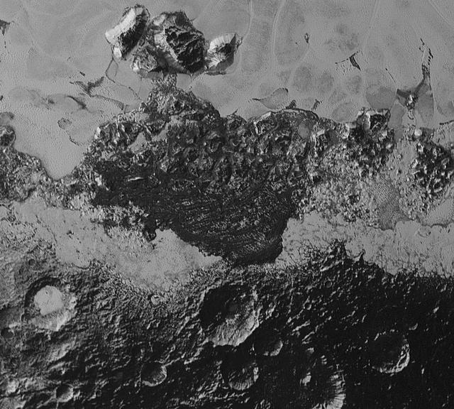
This 220-mile (350-kilometer) wide view of Pluto from NASA's New Horizons spacecraft illustrates the incredible diversity of surface reflectivities and geological landforms on the dwarf planet. The image includes dark, ancient heavily cratered terrain; bright, smooth geologically young terrain; assembled masses of mountains; and an enigmatic field of dark, aligned ridges that resemble dunes; its origin is under debate. The smallest visible features are 0.5 miles (0.8 kilometers) in size. This image was taken as New Horizons flew past Pluto on July 14, 2015, from a distance of 50,000 miles (80,000 kilometers). http://photojournal.jpl.nasa.gov/catalog/PIA19933
![The linear features in this VIS image are called Oti Fossae. Oti Fossae is located on the eastern flank of Arsia Mons and aligns with the regional northeast/southwest trend of the major Tharsis volcanoes. Graben are formed by extension of the crust and faulting. When large amounts of pressure or tension are applied to rocks on timescales that are fast enough that the rock cannot respond by deforming, the rock breaks along faults. In the case of a graben, two parallel faults are formed by extension of the crust and the rock in between the faults drops downward into the space created by the extension. The crustal deformation in this region was from the inflation of the surface by the rise of magma that created the Tharsis volcanoes. Arsia Mons is the southernmost and youngest of the three large, aligned Tharsis volcanoes [Arsia Mons, Pavonis Mons and Ascreaus Mons, from south to north]. This alignment may indicate a large fracture/vent system was responsible for the eruptions that formed all three volcanoes. Arsia Mons is 270 miles (450km) in diameter, almost 12 miles (20km) high, and the summit caldera is 72 miles (120km) wide. For comparison, the largest volcano on Earth is Mauna Loa. From its base on the sea floor, Mauna Loa measures only 6.3 miles high and 75 miles in diameter. Orbit Number: 89712 Latitude: -8.73951 Longitude: 243.785 Instrument: VIS Captured: 2022-03-06 04:33 https://photojournal.jpl.nasa.gov/catalog/PIA25392](https://images-assets.nasa.gov/image/PIA25392/PIA25392~medium.jpg)
The linear features in this VIS image are called Oti Fossae. Oti Fossae is located on the eastern flank of Arsia Mons and aligns with the regional northeast/southwest trend of the major Tharsis volcanoes. Graben are formed by extension of the crust and faulting. When large amounts of pressure or tension are applied to rocks on timescales that are fast enough that the rock cannot respond by deforming, the rock breaks along faults. In the case of a graben, two parallel faults are formed by extension of the crust and the rock in between the faults drops downward into the space created by the extension. The crustal deformation in this region was from the inflation of the surface by the rise of magma that created the Tharsis volcanoes. Arsia Mons is the southernmost and youngest of the three large, aligned Tharsis volcanoes [Arsia Mons, Pavonis Mons and Ascreaus Mons, from south to north]. This alignment may indicate a large fracture/vent system was responsible for the eruptions that formed all three volcanoes. Arsia Mons is 270 miles (450km) in diameter, almost 12 miles (20km) high, and the summit caldera is 72 miles (120km) wide. For comparison, the largest volcano on Earth is Mauna Loa. From its base on the sea floor, Mauna Loa measures only 6.3 miles high and 75 miles in diameter. Orbit Number: 89712 Latitude: -8.73951 Longitude: 243.785 Instrument: VIS Captured: 2022-03-06 04:33 https://photojournal.jpl.nasa.gov/catalog/PIA25392
Today's VIS image shows lava flows near the flank of Pavonis Mons. Pavonis Mons is one of the three large aligned Tharsis region volcanoes. Orbit Number: 77907 Latitude: -1.36831 Longitude: 249.245 Instrument: VIS Captured: 2019-07-08 04:08 https://photojournal.jpl.nasa.gov/catalog/PIA23396
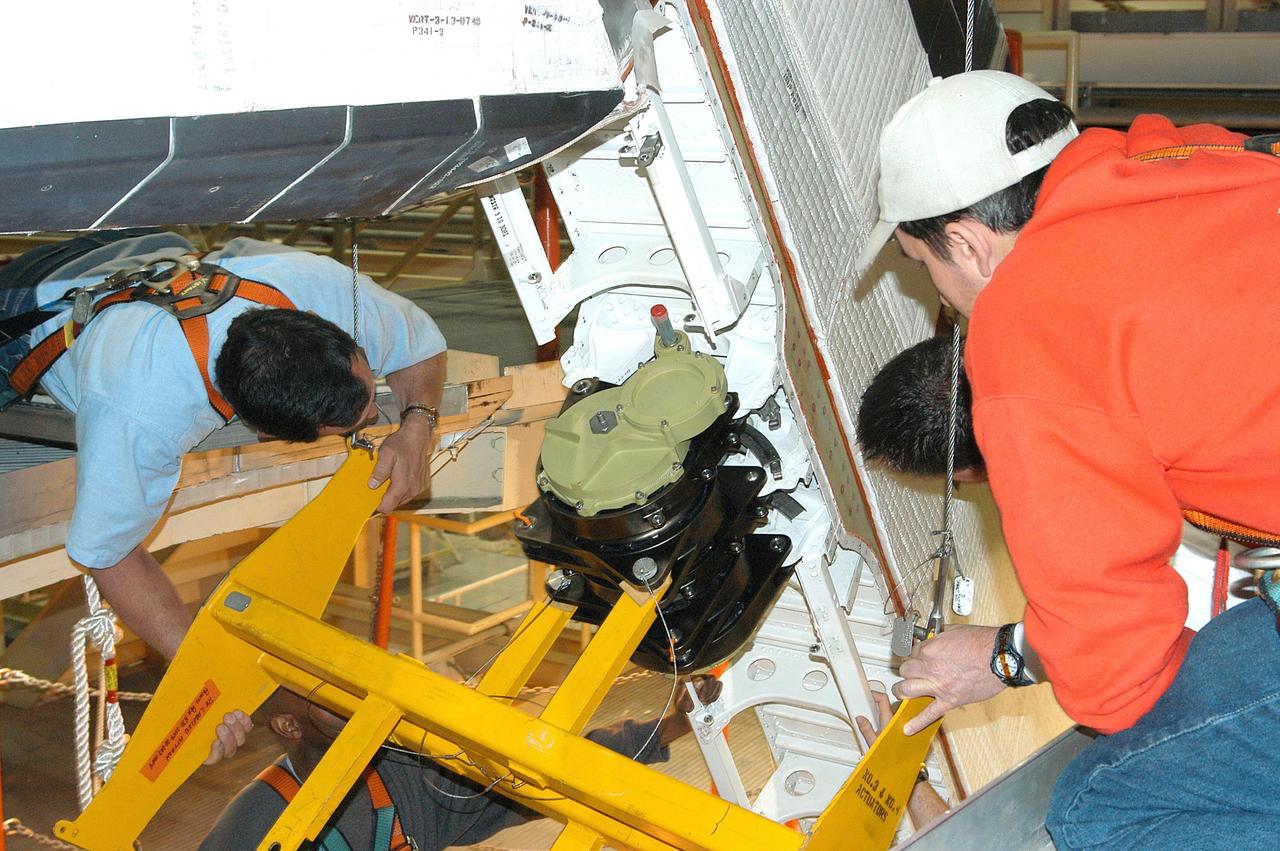
KENNEDY SPACE CENTER, FLA. - United Space Alliance technicians verify the alignment of Rudder Speed Brake actuator No.4 as it is attached to Space Shuttle orbiter Discovery in the Orbiter Processing Facility. Discovery has been assigned to the first Return to Flight mission, STS-114, a logistics flight to the International Space Station.
Today's image shows the southwestern flank of Ascraeus Mons. Ascraeus is the northenmost of the three aligned Tharsis volcanoes and is the tallest at 18,225meters (59,793ft). Orbit Number: 82112 Latitude: 9.73717 Longitude: 253.773 Instrument: VIS Captured: 2020-06-18 10:06 https://photojournal.jpl.nasa.gov/catalog/PIA24141

NASA Deputy Administrator Pam Melroy (front center left) discusses NASA 2040, the agency's strategic initiative for aligning workforce, infrastructure, and technologies to meet the needs of the future, on Nov. 13, 2024, with various groups of employees at the agency's Kennedy Space Center in Florida.
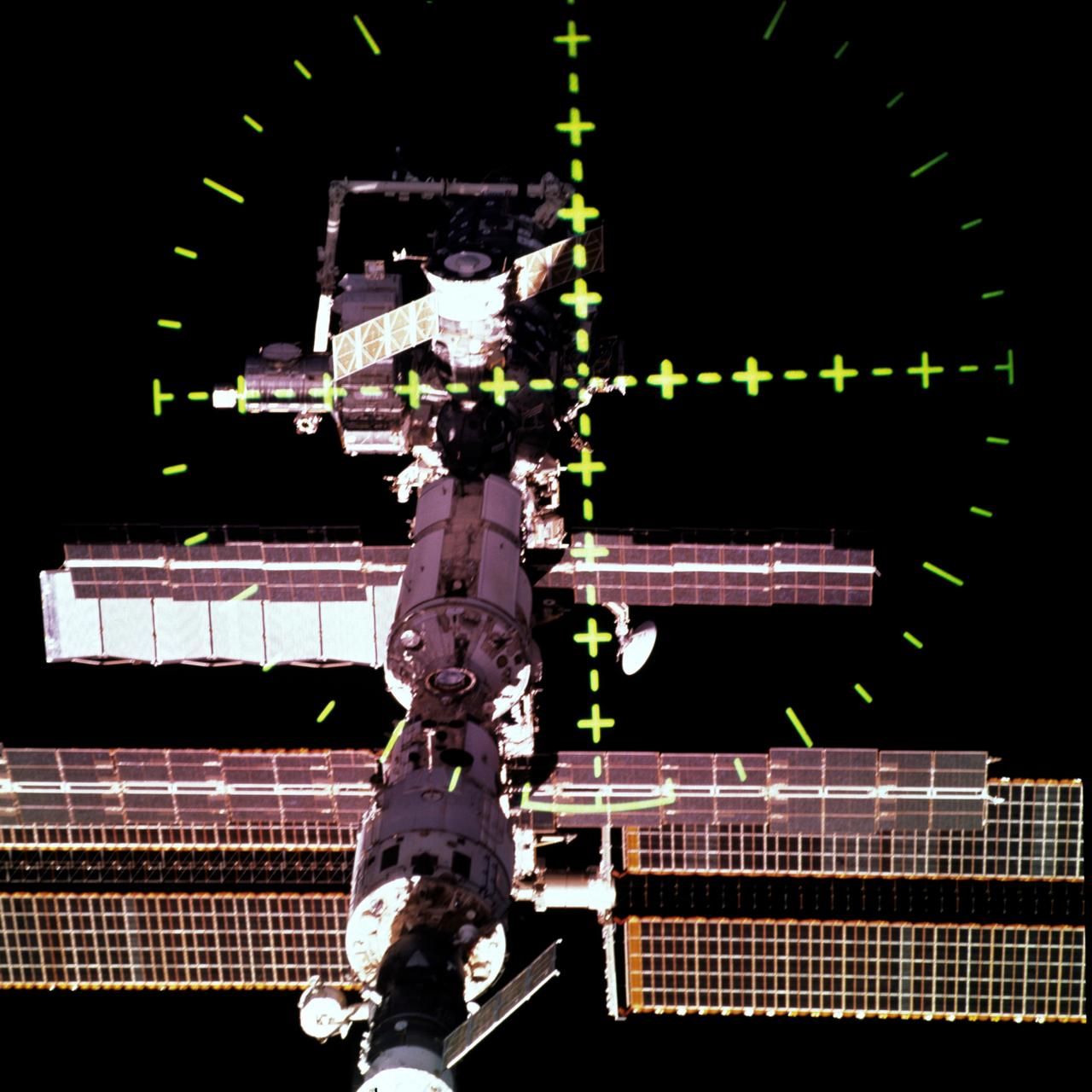
STS105-707-055 (20 August 2001) --- This view of the International Space Station (ISS) was captured with a 70mm handheld camera through the Space Shuttle Discovery's crew optical alignment system (COAS) during separation operations. The undocking took place at 9:52 a.m. (CDT), August 20, 2001.

NASA Deputy Administrator Pam Melroy (front third from left) discusses NASA 2040, the agency's strategic initiative for aligning workforce, infrastructure, and technologies to meet the needs of the future, on Nov. 13, 2024, with various groups of employees at the agency's Kennedy Space Center in Florida.

NASA Deputy Administrator Pam Melroy (front center left) discusses NASA 2040, the agency's strategic initiative for aligning workforce, infrastructure, and technologies to meet the needs of the future, on Nov. 13, 2024, with various groups of employees at the agency's Kennedy Space Center in Florida.
The lava flows and other volcanic features in this VIS image are part of Ascraeus Mons. Ascraeus Mons is the middle volcano in the aligned Tharsis Montes. Orbit Number: 77832 Latitude: 7.57479 Longitude: 251.986 Instrument: VIS Captured: 2019-07-01 23:58 https://photojournal.jpl.nasa.gov/catalog/PIA23392
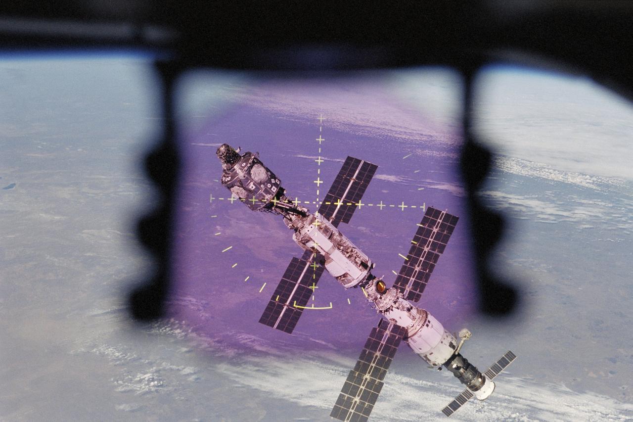
STS106-375-022 (17 September 2000) --- This view of the International Space Station (ISS) was captured with a 35mm handheld camera through the Space Shuttle Atlantis' crew optical alignment system (COAS) during undocking operations. The undocking took place at 10:46 p.m. (CDT) on September 17, 2000.
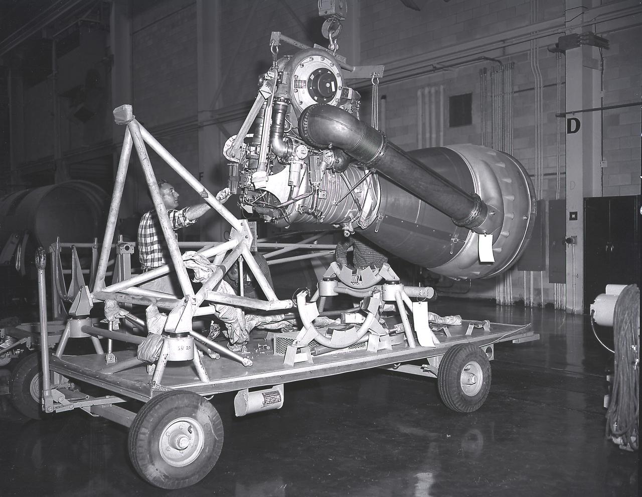
Alignment of the H-1 engine performed in the Army Ballistic Missile Agency (ABMA ), building 4708, in February 1960. A cluster of eight H-1 engines were used to thrust the first stage of the Saturn I launch vehicle. The H-1 engine was developed under the direction of the Marshall Space Flight Center.
The Hyper-Angular Rainbow Polarimeter #2 (HARP2) instrument undergoes Boresight alignment at NASA's Goddard Space Flight Center in Greenbelt, Maryland. HARP2 is one of three instruments on NASA's Plankton, Aerosol, Cloud, ocean Ecosystem (PACE) observatory, it was designed and built by UMBC's Earth and Space Institute.
STS105-E-5067 (12 August 2001) --- One of the STS-105 crew members on the aft flight deck of the Space Shuttle Discovery used a digital still camera to record this close-up view of the docking process between the shuttle and the International Space Station (ISS). The shuttle’s Canadarm or Remote Manipulator System (RMS) arm is in its stowed position at right.
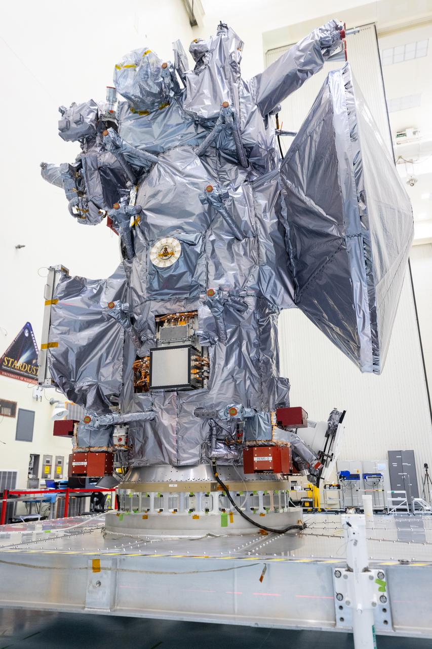
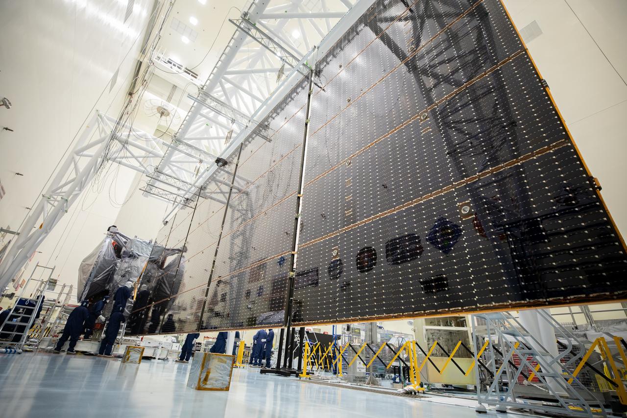
Technicians tested deploying a set of massive solar arrays measuring about 46.5 feet (14.2 meters) long and about 13.5 feet (4.1 meters) high for NASA’s Europa Clipper spacecraft inside the agency’s Payload Hazardous Servicing Facility at Kennedy Space Center in Florida on Wednesday, Aug. 7, 2024. Once launched to study Jupiter’s icy moon, Europa, the solar arrays will fully extend to power the spacecraft to perform flybys to gather science and data to determine if the moon can support habitable conditions.
Technicians tested deploying a set of massive solar arrays measuring about 46.5 feet (14.2 meters) long and about 13.5 feet (4.1 meters) high for NASA’s Europa Clipper spacecraft inside the agency’s Payload Hazardous Servicing Facility at Kennedy Space Center in Florida on Wednesday, Aug. 7, 2024. Once launched to study Jupiter’s icy moon, Europa, the solar arrays will fully extend to power the spacecraft to perform flybys to gather science and data to determine if the moon can support habitable conditions.
Technicians tested deploying a set of massive solar arrays measuring about 46.5 feet (14.2 meters) long and about 13.5 feet (4.1 meters) high for NASA’s Europa Clipper spacecraft inside the agency’s Payload Hazardous Servicing Facility at Kennedy Space Center in Florida on Wednesday, Aug. 7, 2024. Once launched to study Jupiter’s icy moon, Europa, the solar arrays will fully extend to power the spacecraft to perform flybys to gather science and data to determine if the moon can support habitable conditions.
Technicians tested deploying a set of massive solar arrays measuring about 46.5 feet (14.2 meters) long and about 13.5 feet (4.1 meters) high for NASA’s Europa Clipper spacecraft inside the agency’s Payload Hazardous Servicing Facility at Kennedy Space Center in Florida on Wednesday, Aug. 7, 2024. Once launched to study Jupiter’s icy moon, Europa, the solar arrays will fully extend to power the spacecraft to perform flybys to gather science and data to determine if the moon can support habitable conditions.
Technicians tested deploying a set of massive solar arrays measuring about 46.5 feet (14.2 meters) long and about 13.5 feet (4.1 meters) high for NASA’s Europa Clipper spacecraft inside the agency’s Payload Hazardous Servicing Facility at Kennedy Space Center in Florida on Wednesday, Aug. 7, 2024. Once launched to study Jupiter’s icy moon, Europa, the solar arrays will fully extend to power the spacecraft to perform flybys to gather science and data to determine if the moon can support habitable conditions.
Technicians tested deploying a set of massive solar arrays measuring about 46.5 feet (14.2 meters) long and about 13.5 feet (4.1 meters) high for NASA’s Europa Clipper spacecraft inside the agency’s Payload Hazardous Servicing Facility at Kennedy Space Center in Florida on Wednesday, Aug. 7, 2024. Once launched to study Jupiter’s icy moon, Europa, the solar arrays will fully extend to power the spacecraft to perform flybys to gather science and data to determine if the moon can support habitable conditions.
Technicians tested deploying a set of massive solar arrays measuring about 46.5 feet (14.2 meters) long and about 13.5 feet (4.1 meters) high for NASA’s Europa Clipper spacecraft inside the agency’s Payload Hazardous Servicing Facility at Kennedy Space Center in Florida on Wednesday, Aug. 7, 2024. Once launched to study Jupiter’s icy moon, Europa, the solar arrays will fully extend to power the spacecraft to perform flybys to gather science and data to determine if the moon can support habitable conditions.
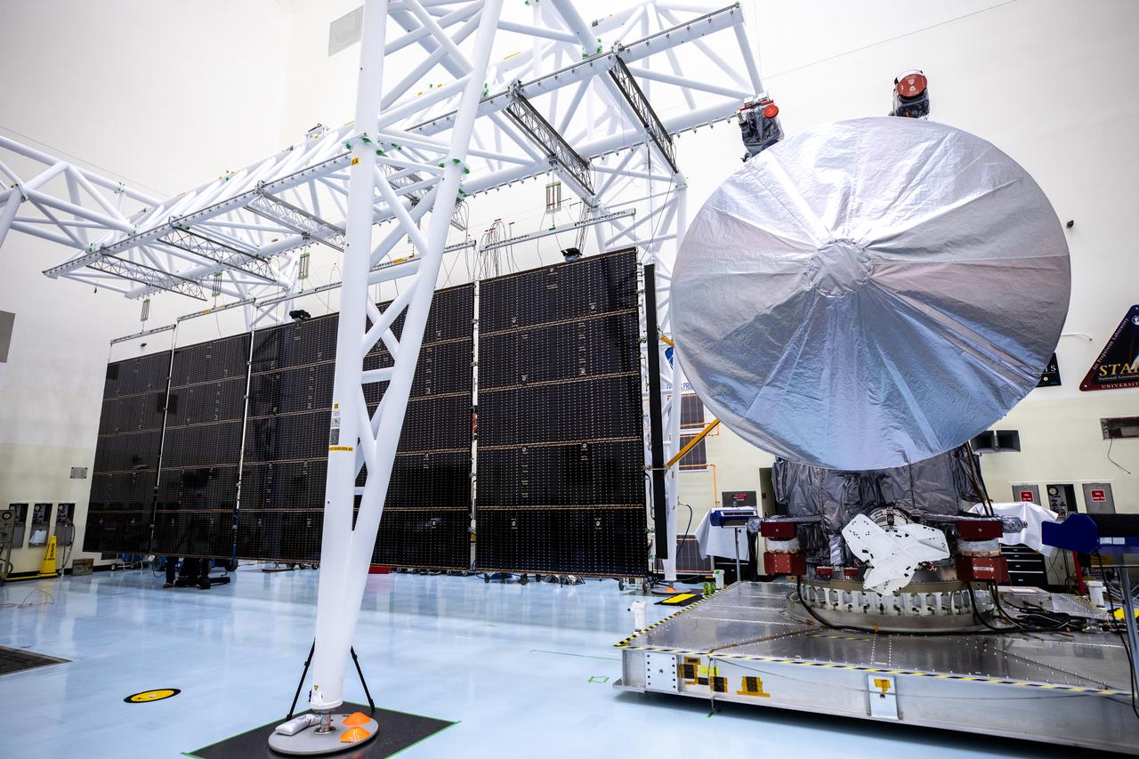
Technicians tested deploying a set of massive solar arrays measuring about 46.5 feet (14.2 meters) long and about 13.5 feet (4.1 meters) high for NASA’s Europa Clipper spacecraft inside the agency’s Payload Hazardous Servicing Facility at Kennedy Space Center in Florida on Wednesday, Aug. 7, 2024. Once launched to study Jupiter’s icy moon, Europa, the solar arrays will fully extend to power the spacecraft to perform flybys to gather science and data to determine if the moon can support habitable conditions.