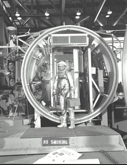
M61-00150 (1961) --- Astronaut John H. Glenn Jr., suited with hose to suit ventilation unit attached, during altitude chamber test. He is standing in the entrance to the test chamber with his helmet visor down. Photo credit: NASA
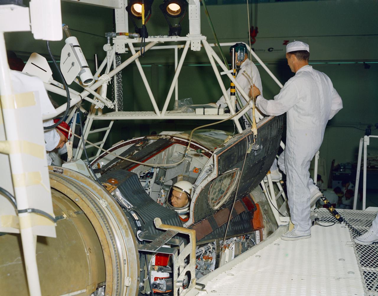
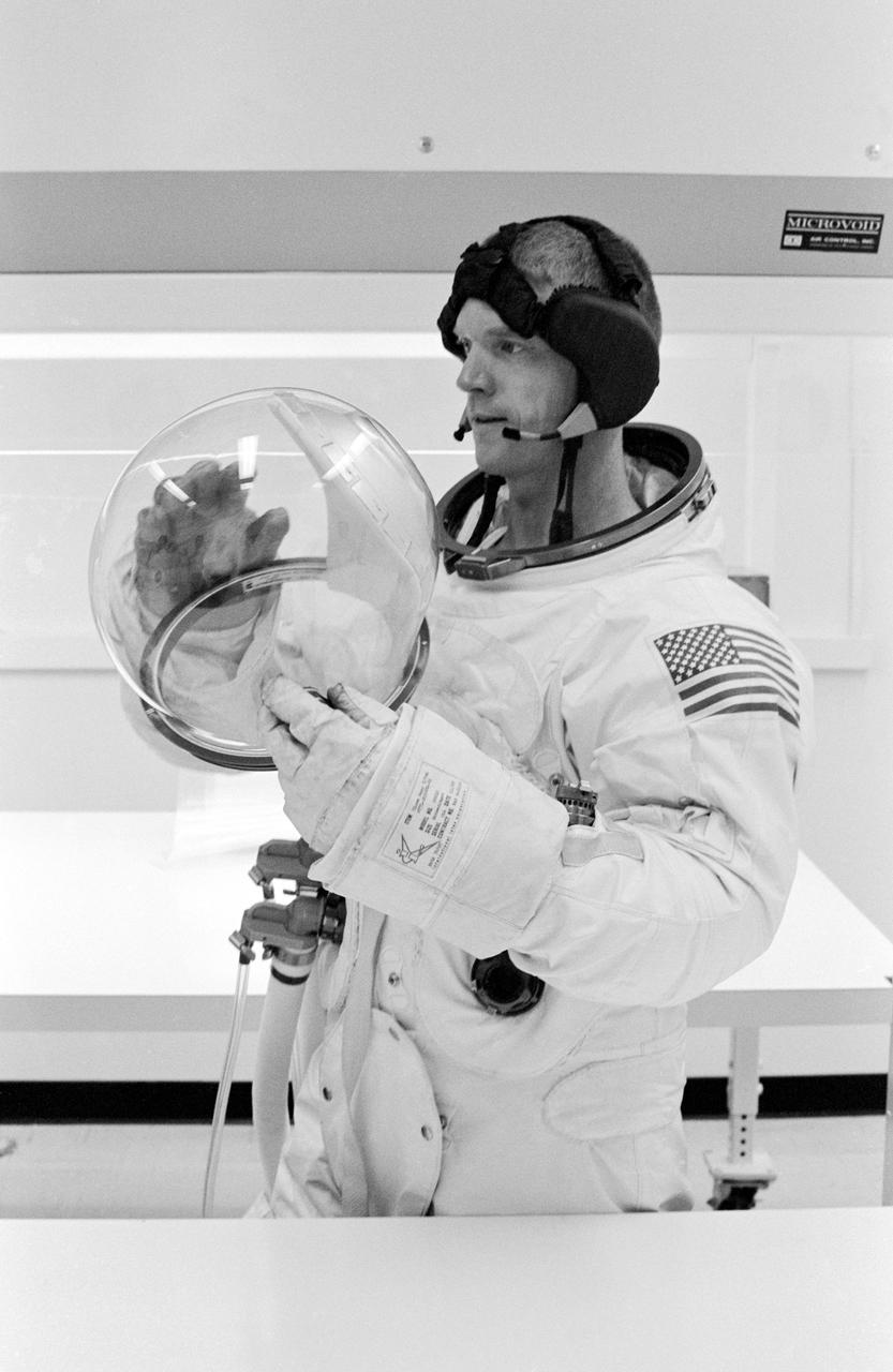
S66-34167 (21 April 1966) --- Astronauts John W. Young (right), command pilot, and Michael Collins, pilot, the prime crew of the Gemini-10 spaceflight, prepare for a Manned Altitude Test Run in the Gemini-10 spacecraft. They are in McDonnell Aircraft's 30-foot altitude chamber. Photo credit: NASA
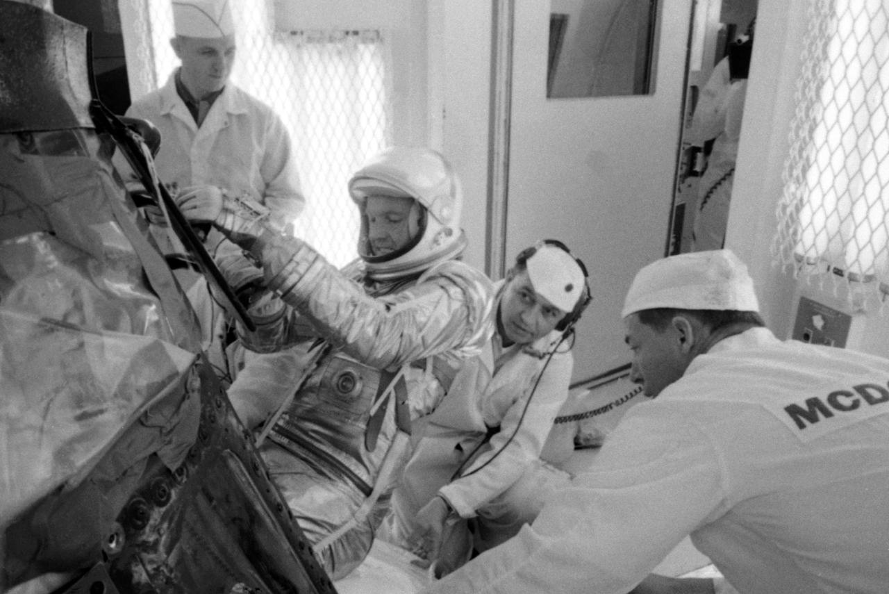
S63-03957 (1963) --- NASA and McDonnell Aircraft Corp. spacecraft technicians assist astronaut L. Gordon Cooper Jr. into his spacecraft prior to undergoing tests in the altitude chamber. These tests are used to determine the operating characteristcs of the overall environmental control system. Photo credit: NASA

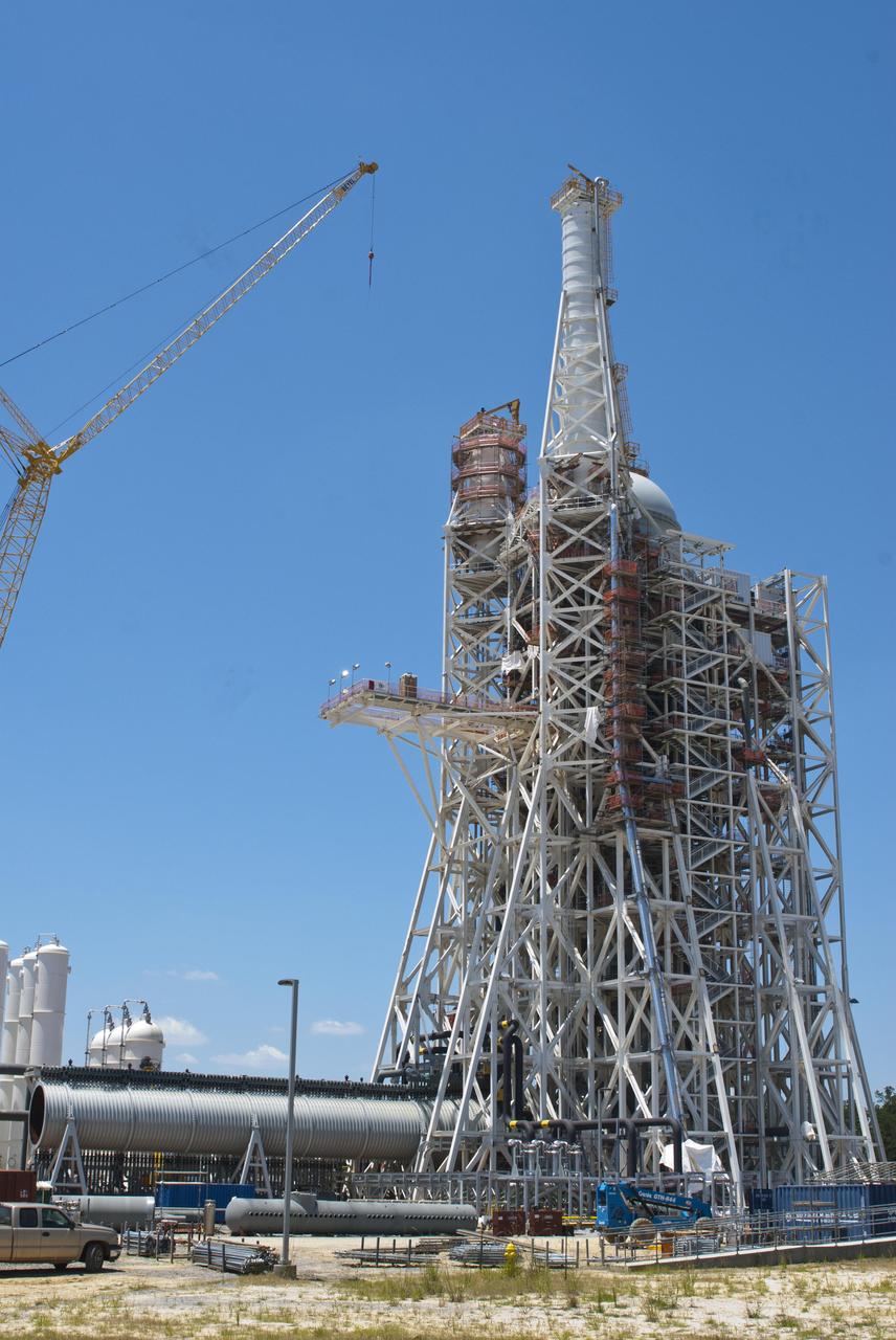
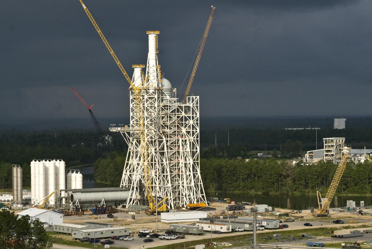
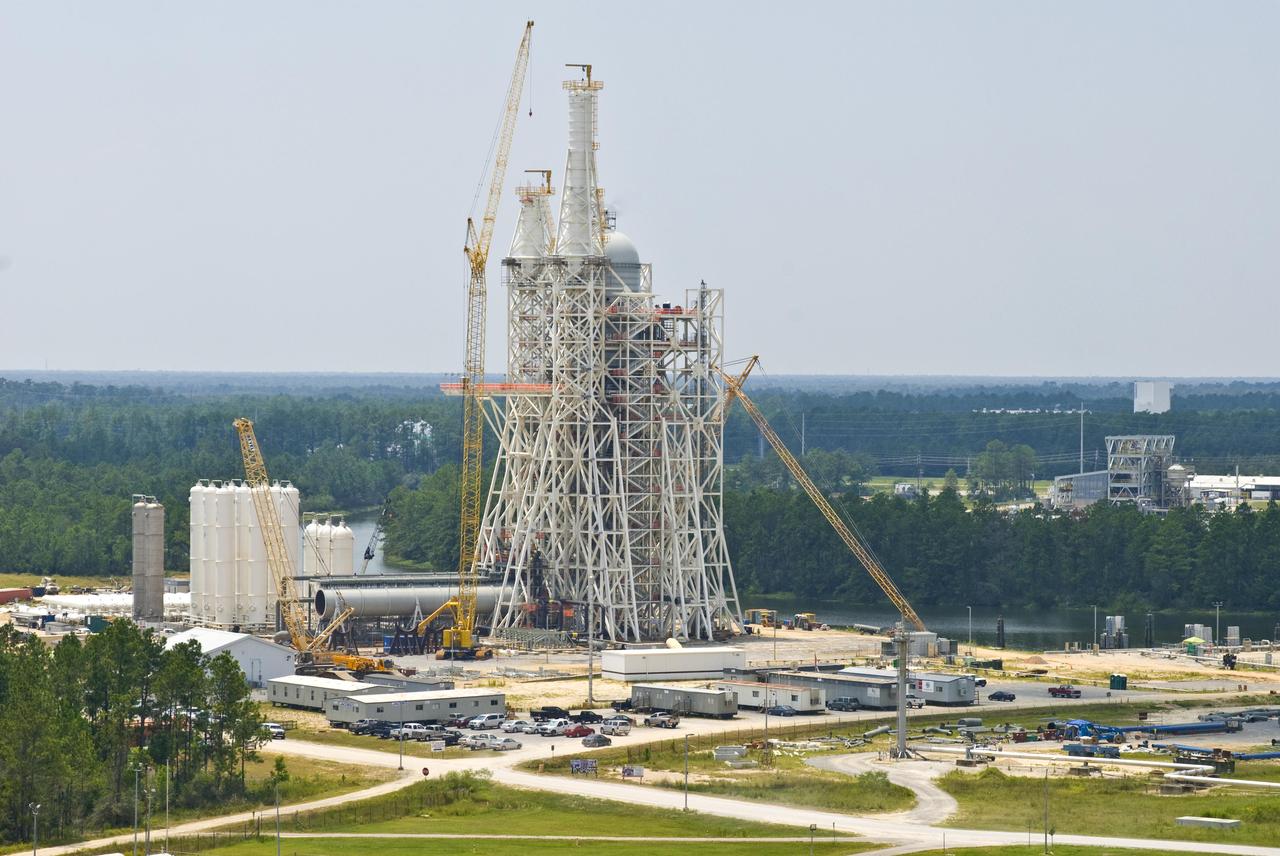
Work continues on the A-3 Test Stand at Stennis Space Center. The new stand will allow operators to test next-generation rocket engines at simulated altitudes up to 100,000 feet. The test stand is scheduled for completion and activation in 2013.
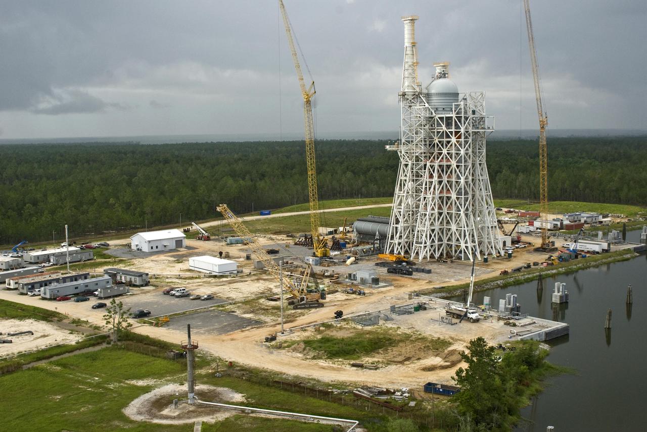
Work continues on the A-3 Test Stand at Stennis Space Center. The new stand will allow operators to test next-generation rocket engines at simulated altitudes up to 100,000 feet. The test stand is scheduled for completion and activation in 2013.

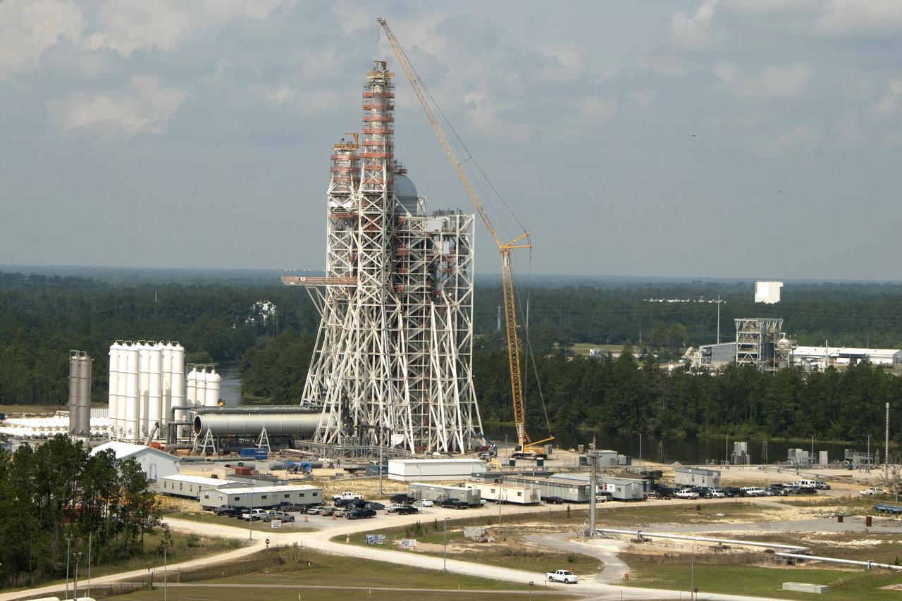
A Stennis Space Center employee works March 2, 2012, to further construction of the A-3 Test Stand, which will enable simulated high-altitude testing of next-generation rocket engines.
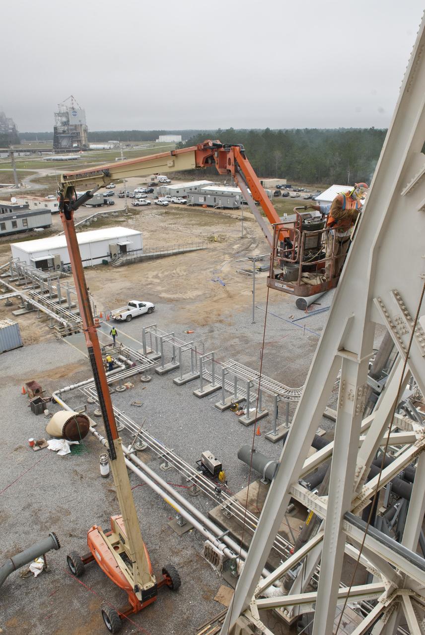
A Stennis Space Center employee works March 2, 2012, to further construction of the A-3 Test Stand, which will enable simulated high-altitude testing of next-generation rocket engines.
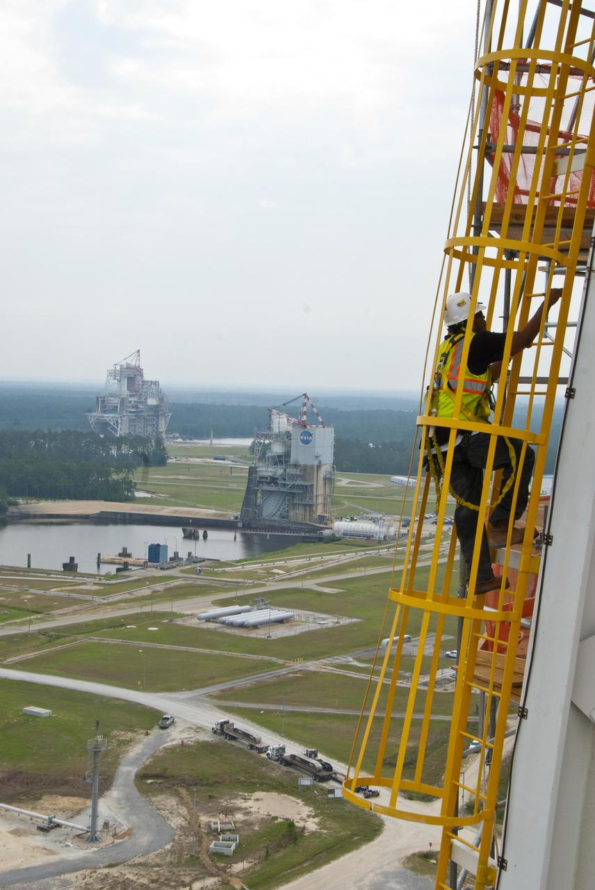
A tethered Stennis Space Center employee climbs an A-3 Test Stand ladder June 8, 2012, against the backdrop of the A-2 and B-1/B-2 stands. The new A-3 Test Stand will enable simulated high-altitude testing of next-generation rocket engines.

A tethered Stennis Space Center employee climbs an A-3 Test Stand ladded June 8, 2012, against the backdrop of the A-2 and B-1/B-2 stands. The new A-3 Test Stand will enable simulated high-altitude testing of next-generation rocket engines.
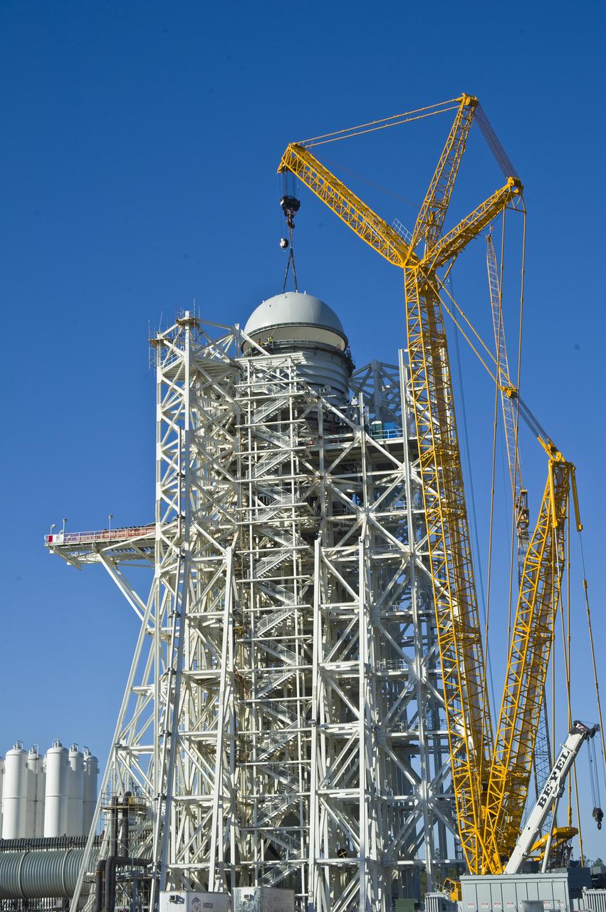
A construction 'topping out' milestone was reached April 13 with placement of the test cell dome atop NASA's new A-3 Test Stand at Stennis Space Center. NASA broke ground in 2007 for the new stand, which is being built to provide simulated high-altitude testing for next-generation rocket engines that could carry humans into deep space.
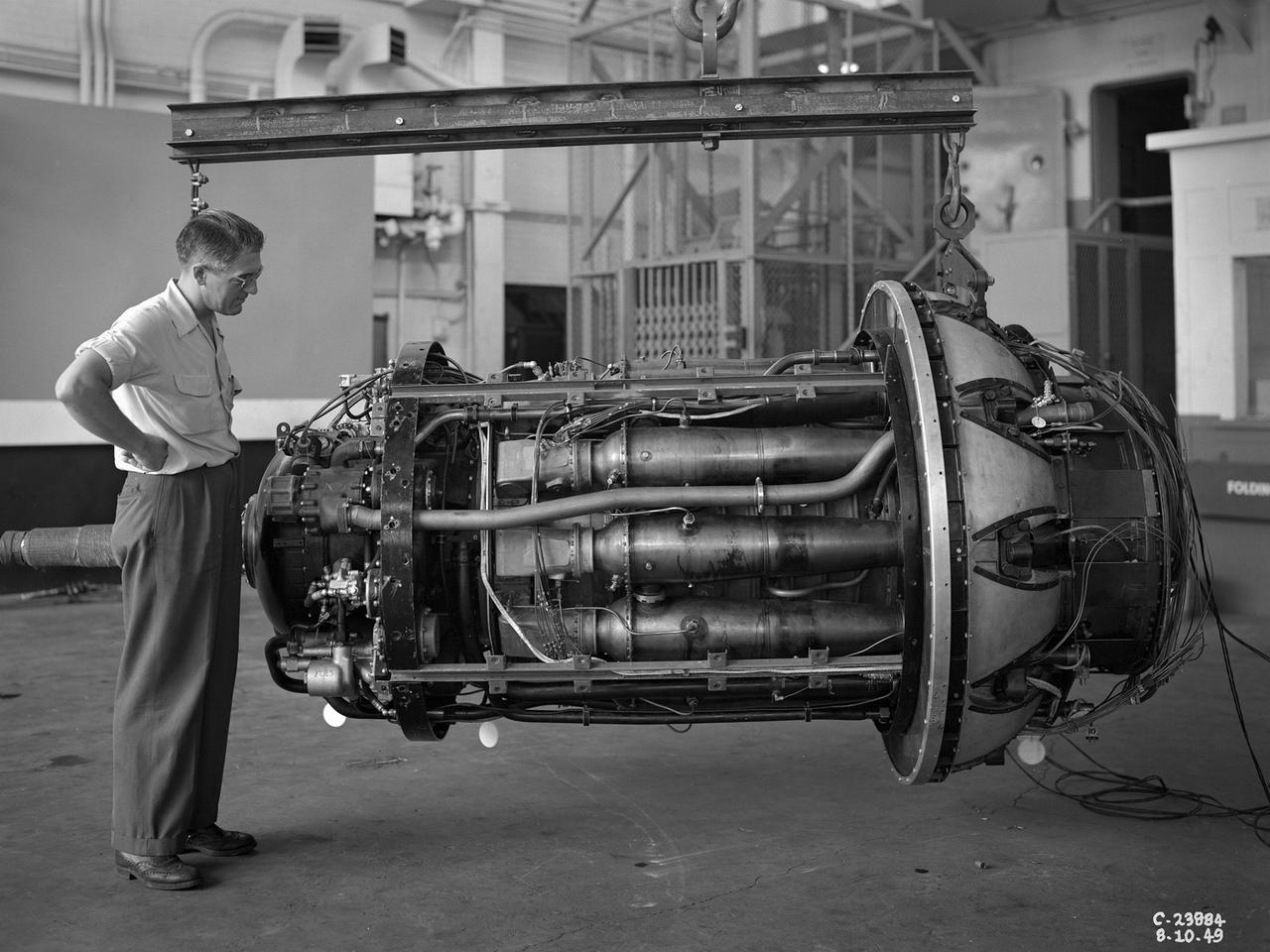
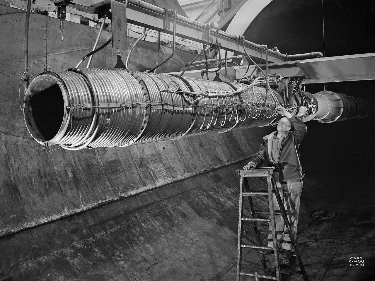
A 3670-horsepower Armstrong-Siddeley Python turboprop being prepared for tests in the Altitude Wind Tunnel at the National Advisory Committee for Aeronautics (NACA) Lewis Flight Propulsion Laboratory. In 1947 Lewis researcher Walter Olsen led a group of representatives from the military, industry, and the NACA on a fact finding mission to investigate the technological progress of British turbojet manufacturers. Afterwards several British engines, including the Python, were brought to Cleveland for testing in Lewis’s altitude facilities. The Python was a 14-stage axial-flow compressor turboprop with a fixed-area nozzle and contra-rotating propellers. Early turboprops combined the turbojet and piston engine technologies. They could move large quantities of air so required less engine speed and thus less fuel. This was very appealing to the military for some applications. The military asked the NACA to compare the Python’s performance at sea to that at high altitudes. The NACA researchers studied the Python in the Altitude Wind Tunnel from July 1949 through January 1950. It was the first time the tunnel was used to study an engine with the sole purpose of learning about, not improving it. They analyzed the engine’s dynamic response using a frequency response method at altitudes between 10,000 to 30,000 feet. Lewis researchers found that they could predict the dynamic response characteristics at any altitude from the data obtained from any other specific altitude. This portion of the testing was completed during a single test run.
A 20-inch diameter ramjet installed in the Altitude Wind Tunnel at the National Advisory Committee for Aeronautics (NACA) Lewis Flight Propulsion Laboratory. The Altitude Wind Tunnel was used in the 1940s to study early ramjet configurations. Ramjets provide a very simple source of propulsion. They are basically a tube which takes in high-velocity air, ignites it, and then expels the expanded airflow at a significantly higher velocity for thrust. Ramjets are extremely efficient and powerful but can only operate at high speeds. Therefore a turbojet or rocket was needed to launch the vehicle. This NACA-designed 20-inch diameter ramjet was installed in the Altitude Wind Tunnel in May 1945. The ramjet was mounted under a section of wing in the 20-foot diameter test section with conditioned airflow ducted directly to the engine. The mechanic in this photograph was installing instrumentation devices that led to the control room. NACA researchers investigated the ramjet’s overall performance at simulated altitudes up to 47,000 feet. Thrust measurements from these runs were studied in conjunction with drag data obtained during small-scale studies in the laboratory’s small supersonic tunnels. An afterburner was attached to the ramjet during the portions of the test program. The researchers found that an increase in altitude caused a reduction in the engine’s horsepower. They also determined the optimal configurations for the flameholders, which provided the engine’s ignition source.
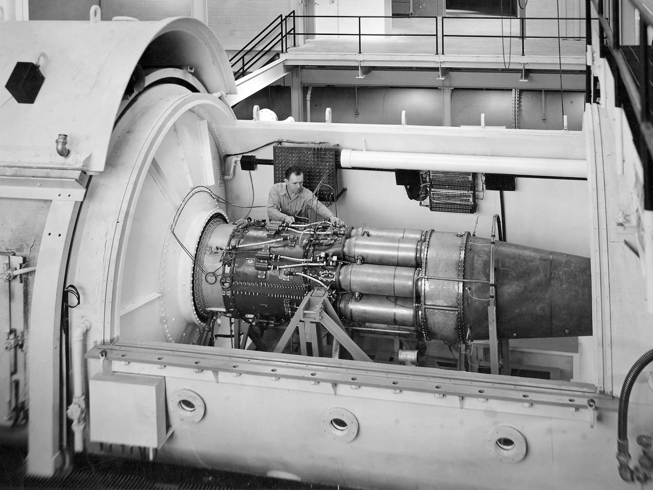
One of the two altitude simulating-test chambers in Engine Research Building at the National Advisory Committee for Aeronautics (NACA) Lewis Flight Propulsion Laboratory. The two chambers were collectively referred to as the Four Burner Area. NACA Lewis’ Altitude Wind Tunnel was the nation’s first major facility used for testing full-scale engines in conditions that realistically simulated actual flight. The wind tunnel was such a success in the mid-1940s that there was a backlog of engines waiting to be tested. The Four Burner chambers were quickly built in 1946 and 1947 to ease the Altitude Wind Tunnel’s congested schedule. The Four Burner Area was located in the southwest wing of the massive Engine Research Building, across the road from the Altitude Wind Tunnel. The two chambers were 10 feet in diameter and 60 feet long. The refrigeration equipment produced the temperatures and the exhauster equipment created the low pressures present at altitudes up to 60,000 feet. In 1947 the Rolls Royce Nene was the first engine tested in the new facility. The mechanic in this photograph is installing a General Electric J-35 engine. Over the next ten years, a variety of studies were conducted using the General Electric J-47 and Wright Aeronautical J-65 turbojets. The two test cells were occasionally used for rocket engines between 1957 and 1959, but other facilities were better suited to the rocket engine testing. The Four Burner Area was shutdown in 1959. After years of inactivity, the facility was removed from the Engine Research Building in late 1973 in order to create the High Temperature and Pressure Combustor Test Facility.
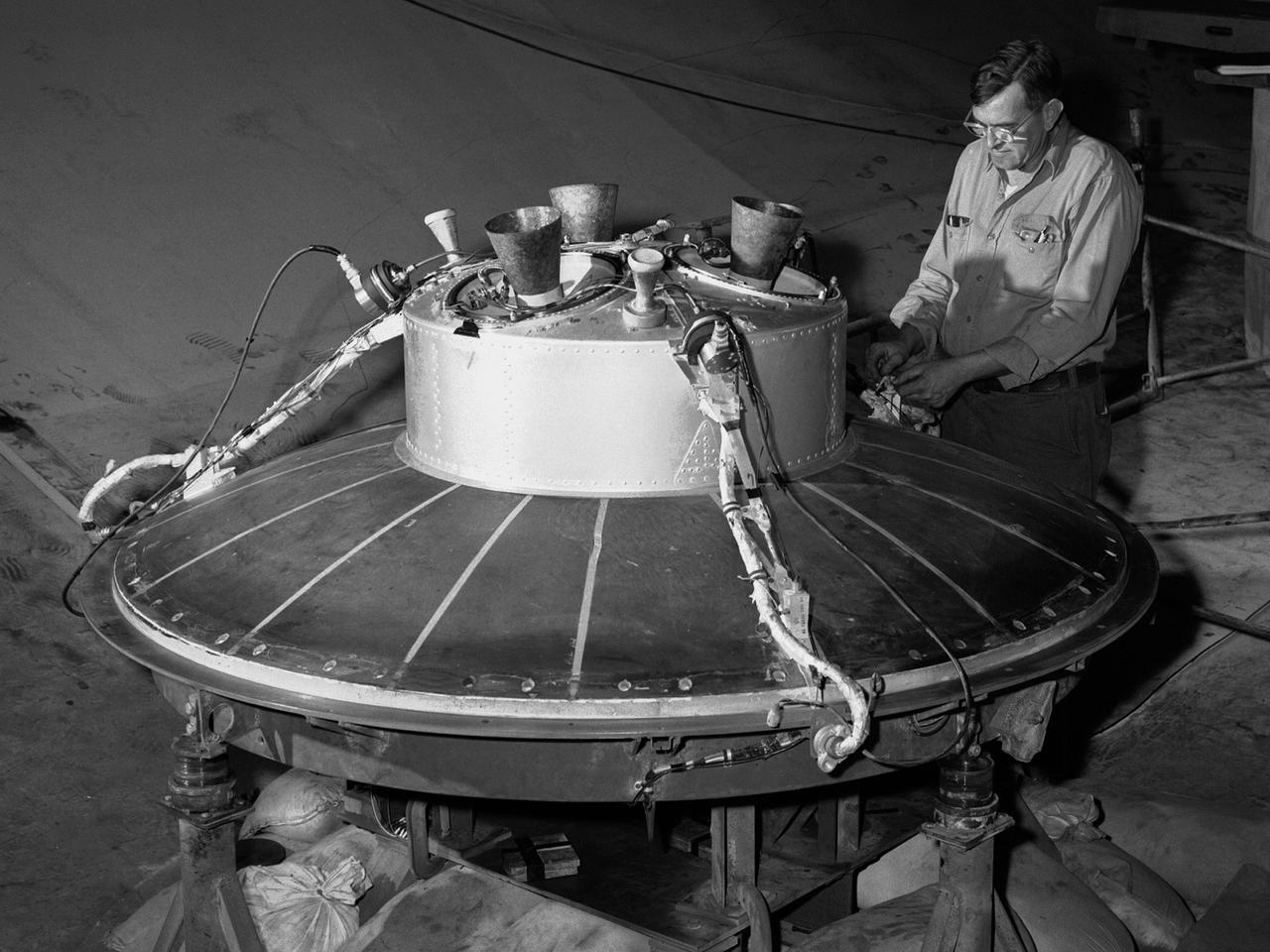
A mechanic at the National Aeronautics and Space Administration (NASA) Lewis Research Center prepares the inverted base of a Mercury capsule for a test of its posigrade retrorockets inside the Altitude Wind Tunnel. In October 1959 NASA’s Space Task Group allocated several Project Mercury assignments to Lewis. The Altitude Wind Tunnel was modified to test the Atlas separation system, study the escape tower rocket plume, train astronauts to bring a spinning capsule under control, and calibrate the capsule’s retrorockets. The turning vanes, makeup air pipes, and cooling coils were removed from the wide western end of the tunnel to create a 51-foot diameter test chamber. The Mercury capsule had a six-rocket retro-package affixed to the bottom of the capsule. Three of these were posigrade rockets used to separate the capsule from the booster and three were retrograde rockets used to slow the capsule for reentry into the earth’s atmosphere. Performance of the retrorockets was vital since there was no backup system. Qualification tests of the retrorockets began in April 1960 on a retrograde thrust stand inside the southwest corner of the Altitude Wind Tunnel. These studies showed that a previous issue concerning the delayed ignition of the propellant had been resolved. Follow-up test runs verified reliability of the igniter’s attachment to the propellant. In addition, the capsule’s retrorockets were calibrated so they would not alter the capsule’s attitude when fired.
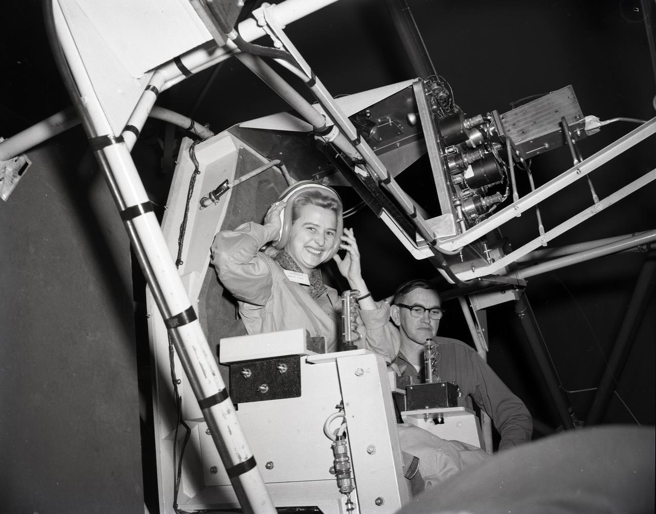
JERRIE COBB - PILOT - TESTING GIMBAL RIG IN THE ALTITUDE WIND TUNNEL, AWT

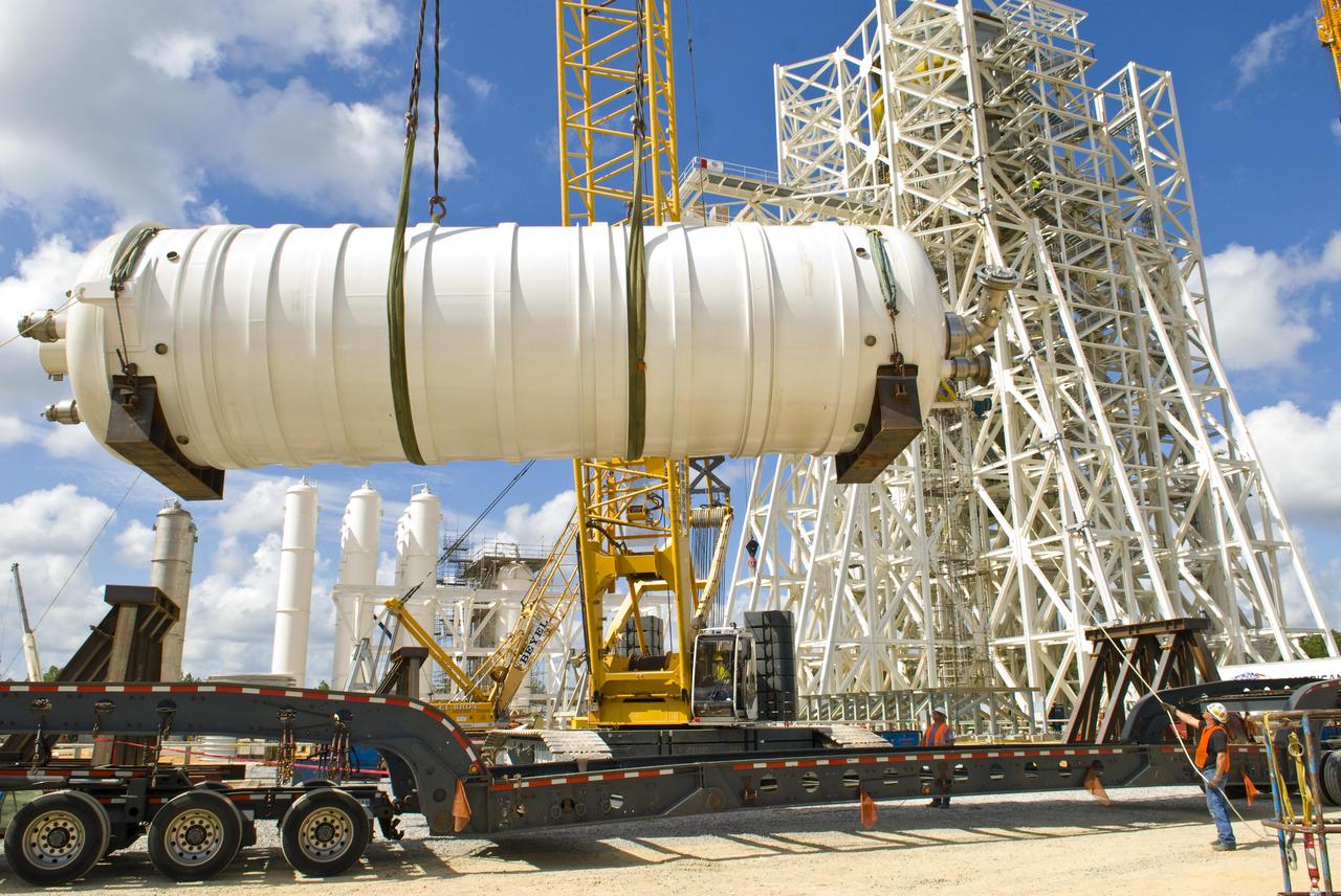
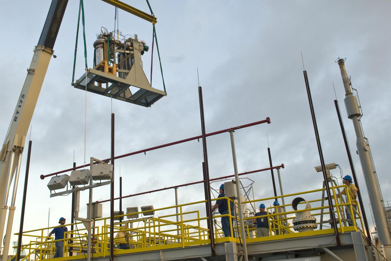
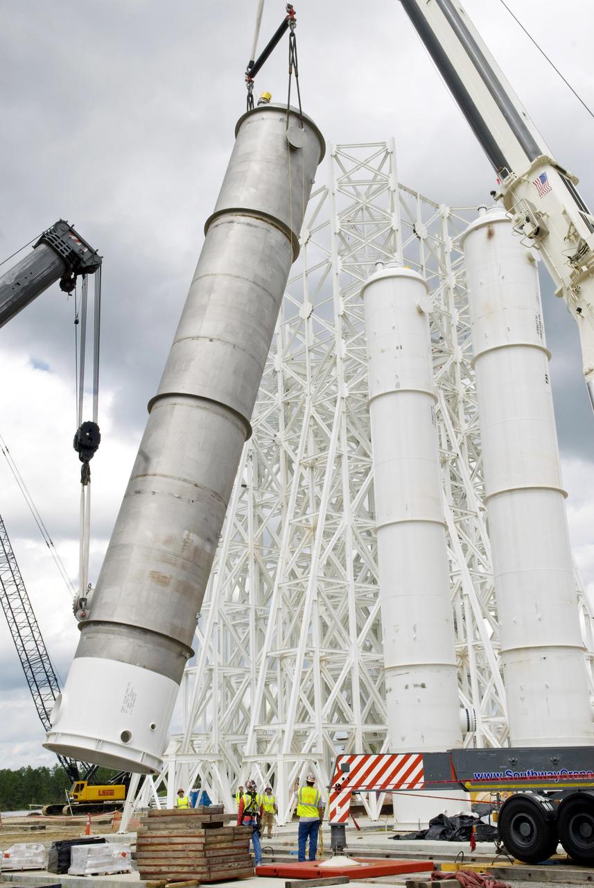
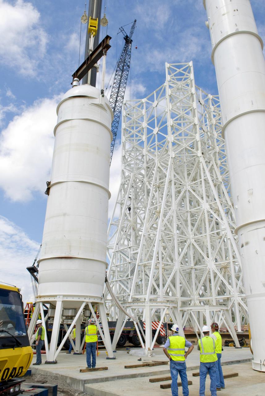
A water tank is lifted into place at the A-3 Test Stand being built at NASA's John C. Stennis Space Center. Fourteen water, liquid oxygen (LOX) and isopropyl alcohol (IPA) tanks are being installed to support the chemical steam generators to be used on the A-3 Test Stand. The IPA and LOX tanks will provide fuel for the generators. The water will allow the generators to produce steam that will be used to reduce pressure inside the stand's test cell diffuser, enabling operators to simulate altitudes up to 100,000 feet. In that way, operators can perform the tests needed on rocket engines being built to carry humans back to the moon and possibly beyond. The A-3 Test Stand is set for completion and activation in 2011.
A water tank is lifted into place at the A-3 Test Stand being built at NASA's John C. Stennis Space Center. Fourteen water, liquid oxygen (LOX) and isopropyl alcohol (IPA) tanks are being installed to support the chemical steam generators to be used on the A-3 Test Stand. The IPA and LOX tanks will provide fuel for the generators. The water will allow the generators to produce steam that will be used to reduce pressure inside the stand's test cell diffuser, enabling operators to simulate altitudes up to 100,000 feet. In that way, operators can perform the tests needed on rocket engines being built to carry humans back to the moon and possibly beyond. The A-3 Test Stand is set for completion and activation in 2011.
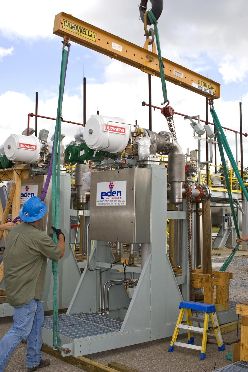
The first of nine chemical steam generator (CSG) units that will be used on the A-3 Test Stand is prepared for installation Oct. 24, 2010, at John C. Stennis Space Center. The unit was installed at the E-2 Test Stand for verification and validation testing before it is moved to the A-3 stand. Steam generated by the nine CSG units that will be installed on the A-3 stand will create a vacuum that allows Stennis operators to test next-generation rocket engines at simulated altitudes up to 100,000 feet.
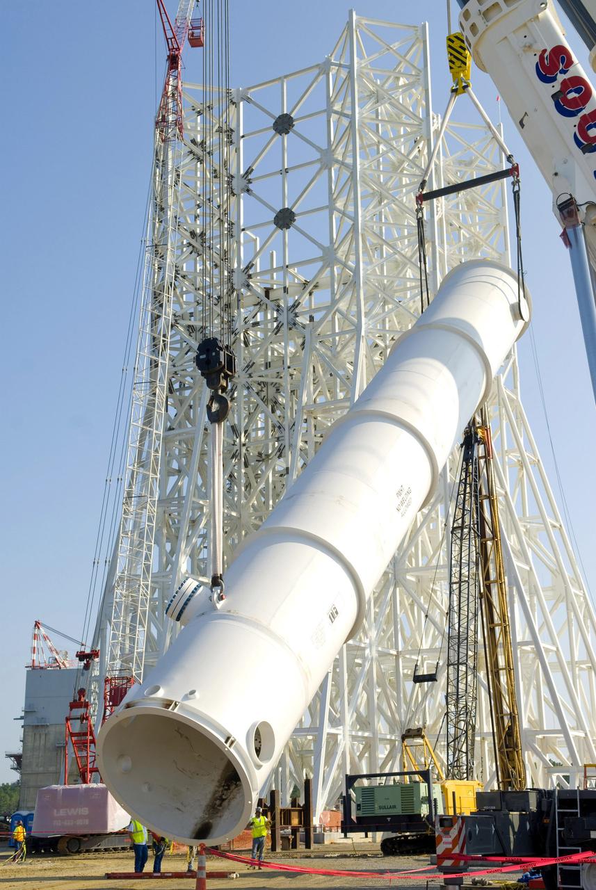
An 80,000-gallon liquid hydrogen tank is placed at the A-3 Test Stand construction site on Sept. 24, 2010. The tank will provide propellant for tests of next-generation rocket engines at the stand. It will be placed upright on top of the stand, helping to increase the overall height to 300 feet. Once completed, the A-3 Test Stand will enable operators to test rocket engines at simulated altitudes of up to 100,000 feet. The A-3 stand is the first large rocket engine test structure to be built at Stennis Space Center since the 1960s.
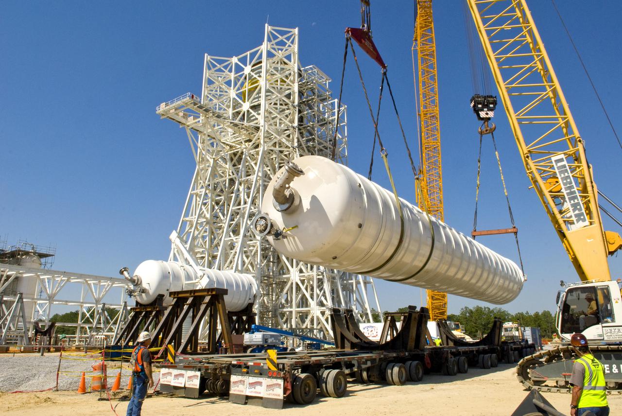
A 35,000-gallon liquid oxygen tank is placed at the A-3 Test Stand construction site on Sept. 24, 2010. The tank will provide propellant for tests of next-generation rocket engines at the stand. It will be placed upright on top of the stand, helping to increase the overall height to 300 feet. Once completed, the A-3 Test Stand will enable operators to test rocket engines at simulated altitudes of up to 100,000 feet. The A-3 stand is the first large rocket engine test structure to be built at Stennis Space Center since the 1960s.
The first of nine chemical steam generator (CSG) units that will be used on the A-3 Test Stand is hoisted into place at the E-2 Test Stand at John C. Stennis Space Center on Oct. 24, 2010. The unit was installed at the E-2 stand for verification and validation testing before it is moved to the A-3 stand. Steam generated by the nine CSG units that will be installed on the A-3 stand will create a vacuum that allows Stennis operators to test next-generation rocket engines at simulated altitudes up to 100,000 feet.
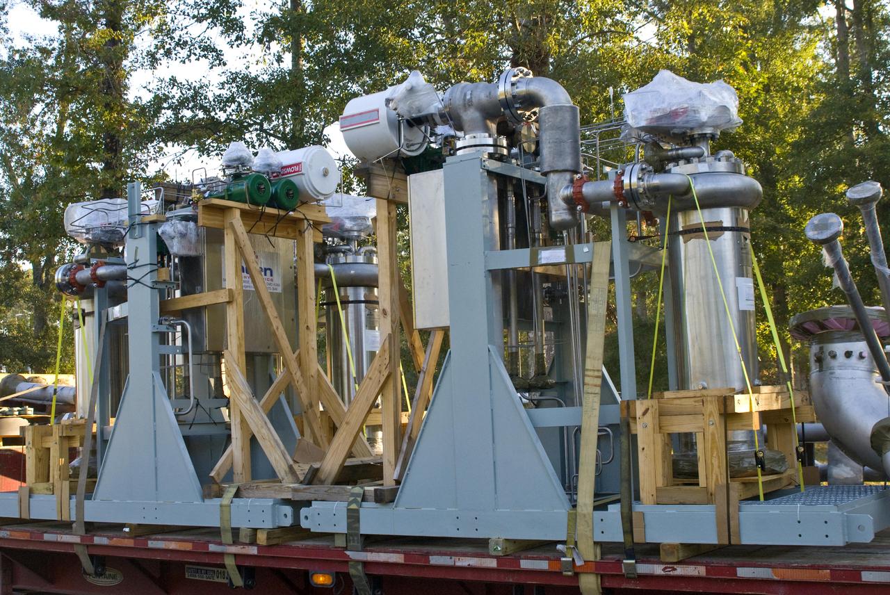
The first of nine chemical steam generator (CSG) units that will be used on the A-3 Test Stand arrived at John. C. Stennis Space Center on Oct. 22, 2010. The unit was installed at the E-2 Test Stand for verification and validation testing before it is moved to the A-3 stand. Steam generated by the nine CSG units that will be installed on the A-3 stand will create a vacuum that allows Stennis operators to test next-generation rocket engines at simulated altitudes up to 100,000 feet.
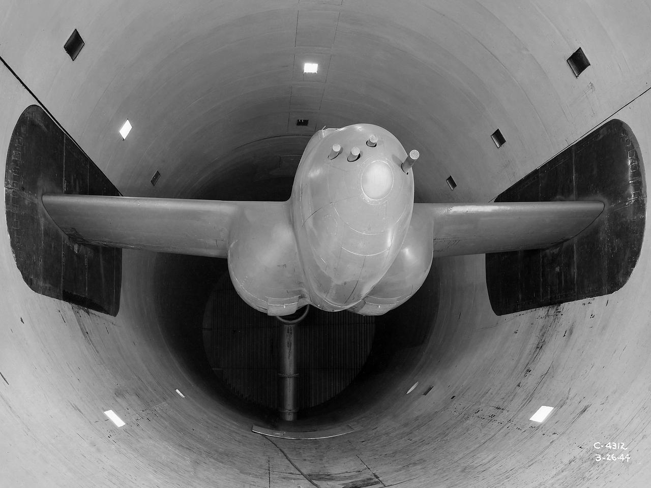
The Altitude Wind Tunnel (AWT) was the National Advisory Committee for Aeronautics (NACA) Aircraft Engine Research Laboratory’s largest and most important test facility in the 1940s. The AWT employed massive cooling and exhaust systems to simulate conditions found at high altitudes. The facility was originally designed to test large piston engines in a simulated flight environment. The introduction of the turbojet during the tunnel’s construction, however, changed the facility’s focus before it became operational. Its first test program was a study of the Bell YP–59A Airacomet and its General Electric I–16 turbojets. The Airacomet was the United States’ first attempt to build a jet aircraft. 1600-horsepower centrifugal engines based on an early design by British engineer Frank Whittle were incorporated into an existing Bell airframe. In October 1942 the Airacomet was secretly test flown in the California desert. The aircraft’s performance was limited, however, and the NACA was asked to study the engines in the AWT. The wind tunnel’s 20-foot-diameter test section was large enough to accommodate entire aircraft with its wing tips and tail removed. The I-16 engines were studied exhaustively in early 1944. They first analyzed the engines in their original configuration and then implemented a boundary layer removal duct, a new nacelle inlet, and new cooling seals. Tests of the modified version showed that the improved distribution of airflow increased the I–16’s performance by 25 percent. The Airacomet never overcame some of its inherent design issues, but the AWT went on to study nearly every emerging US turbojet model during the next decade.
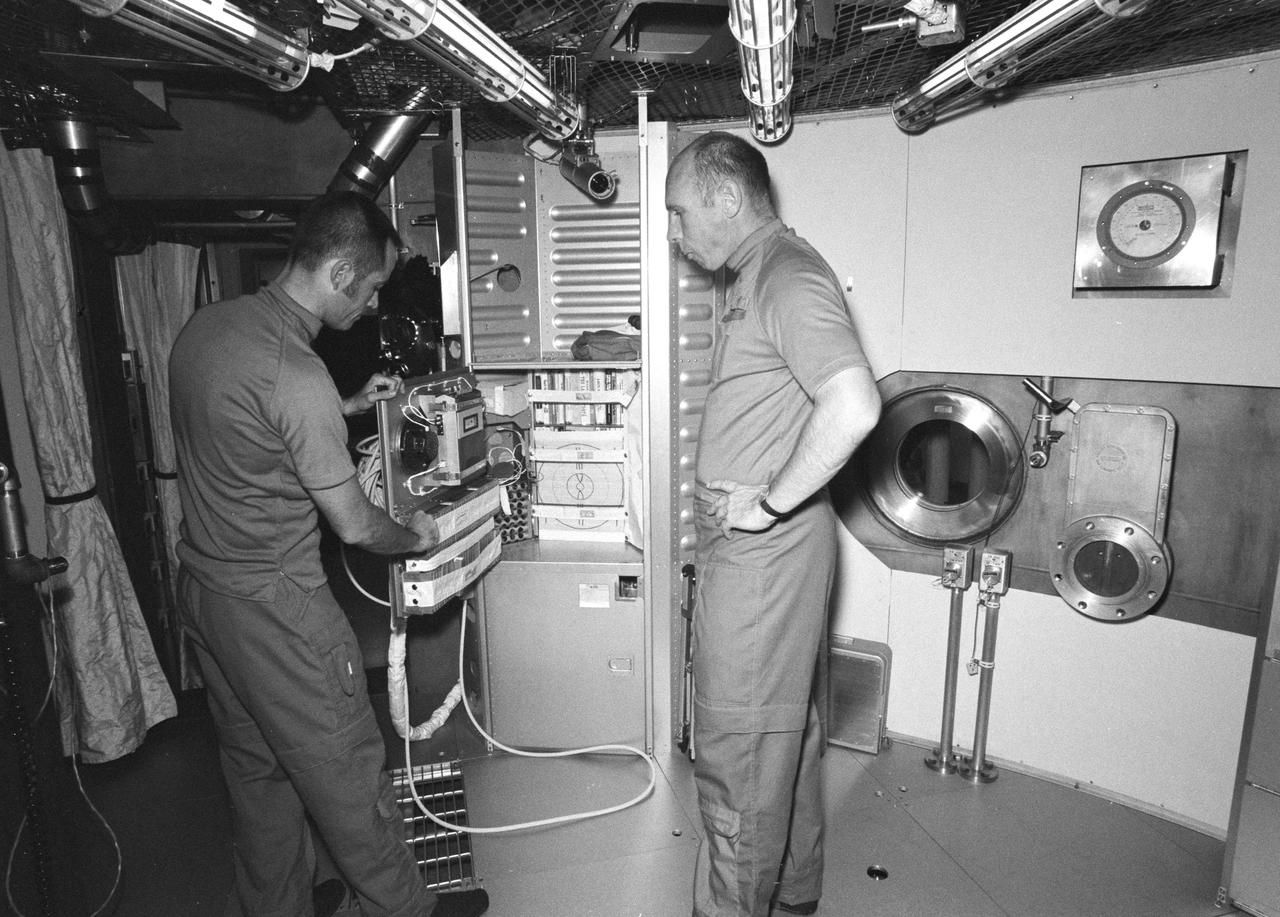
S72-41858 (15 June 1972) --- Astronauts Robert L. Crippen, left, Skylab Medical Experiment Altitude Test (SMEAT) crew commander, and Dr. William E. Thornton, SMEAT science pilot, stand at the cabinet containing off duty recreation equipment. They are two members of a three-man SMEAT crew who will spend up to 56 days in the Crew Systems Division's 20-foot altitude chamber at the NASA Manned Spacecraft Center (MSC) beginning in mid-July to obtain medical data and evaluate medical experiment equipment for Skylab. Astronaut Karol J. Bobko, SMEAT pilot, the third crew member is not shown in this view. Photo credit: NASA
An isopropyl alcohol (IPA) tank is lifted into place at the A-3 Test Stand being built at NASA's John C. Stennis Space Center. Fourteen IPA, water and liquid oxygen (LOX) tanks are being installed to support the chemical steam generators to be used on the A-3 Test Stand. The IPA and LOX tanks will provide fuel for the generators. The water will allow the generators to produce steam that will be used to reduce pressure inside the stand's test cell diffuser, enabling operators to simulate altitudes up to 100,000 feet. In that way, operators can perform the tests needed on rocket engines being built to carry humans back to the moon and possibly beyond. The A-3 Test Stand is set for completion and activation in 2011.

A liquid oxygen (LOX) tank is lifted into place at the A-3 Test Stand being built at NASA's John C. Stennis Space Center. Fourteen LOX, isopropyl alcohol (IPA) and water tanks are being installed to support the chemical steam generators to be used on the A-3 Test Stand. The IPA and LOX tanks will provide fuel for the generators. The water will allow the generators to produce steam that will be used to reduce pressure inside the stand's test cell diffuser, enabling operators to simulate altitudes up to 100,000 feet. In that way, operators can perform the tests needed on rocket engines being built to carry humans back to the moon and possibly beyond. The A-3 Test Stand is set for completion and activation in 2011.
A liquid oxygen (LOX) tank is lifted into place at the A-3 Test Stand being built at NASA's John C. Stennis Space Center. Fourteen LOX, isopropyl alcohol (IPA) and water tanks are being installed to support the chemical steam generators to be used on the A-3 Test Stand. The IPA and LOX tanks will provide fuel for the generators. The water will allow the generators to produce steam that will be used to reduce pressure inside the stand's test cell diffuser, enabling operators to simulate altitudes up to 100,000 feet. In that way, operators can perform the tests needed on rocket engines being built to carry humans back to the moon and possibly beyond. The A-3 Test Stand is set for completion and activation in 2011.

John C. Stennis Space Center employees complete installation of a chemical steam generator (CSG) unit at the site's E-2 Test Stand. On Oct. 24, 2010. The unit will undergo verification and validation testing on the E-2 stand before it is moved to the A-3 Test Stand under construction at Stennis. Each CSG unit includes three modules. Steam generated by the nine CSG units that will be installed on the A-3 stand will create a vacuum that allows Stennis operators to test next-generation rocket engines at simulated altitudes up to 100,000 feet.
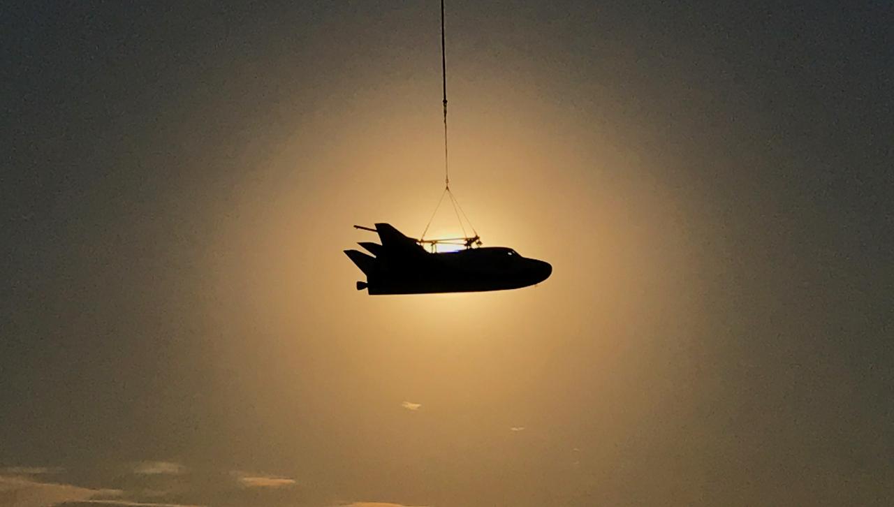
Sierra Nevada Corporation’s Dream Chaser completed an important step toward orbital flight with a successful captive carry test at NASA’s Armstrong Flight Research Center in California, located on Edwards Air Force Base. A helicopter successfully carried a Dream Chaser test article, which has the same specifications as a flight-ready spacecraft, to the same altitude and flight conditions of an upcoming free flight test. The Dream Chaser is a lifting-body, winged spacecraft that will fly back to Earth in a manner similar to NASA’s space shuttles. The successful captive carry test clears the way for a free flight test of the spacecraft later this year in which the uncrewed Dream Chaser will be released to glide on its own and land.

S66-32530 (14 April 1966) --- Astronauts John W. Young (right), command pilot, and Michael Collins, pilot, the prime crew of the Gemini-10 spaceflight, prepare for a Manned Altitude Test Run in the Gemini-10 spacecraft. They are in McDonnell Aircraft's 30-feet altitude chamber. Photo credit: NASA
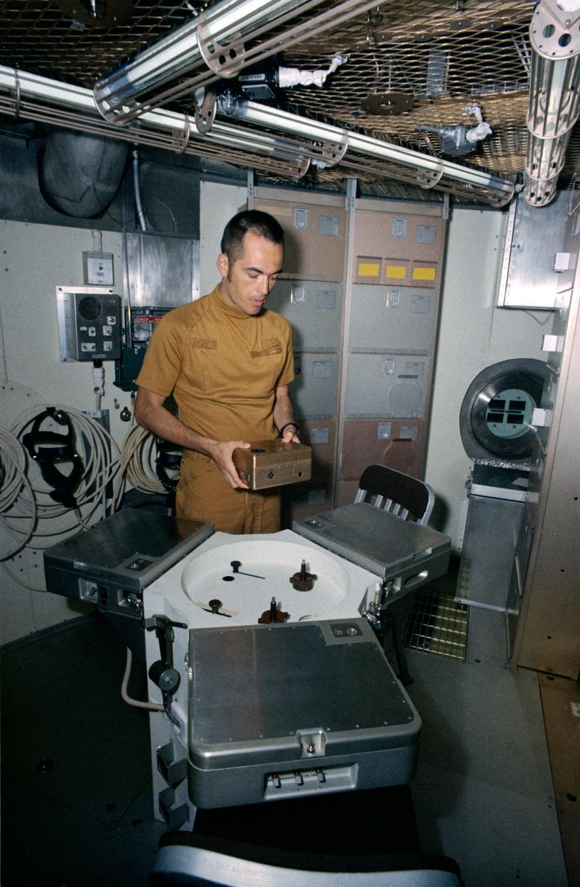
S72-43280 (15 June 1972) --- Astronaut Robert L. Crippen, Skylab Medical Experiment Altitude Test (SMEAT) commander, holds the training model of Skylab experiment T003, the aerosol analysis test, in this preview of SMEAT activity. He is part of a three-man SMEAT crew who will spend up to 56 days in the Crew Systems Division's 20-foot altitude chamber at the NASA Manned Spacecraft Center (MSC) beginning in mid-July to obtain medical data and evaluate medical experiment equipment for Skylab. The two crew members not shown in this view are astronauts Karol J. Bobko, SMEAT pilot, and Dr. William E. Thornton, SMEAT science pilot. Photo credit: NASA

An inlet duct lowered into the 20-foot diameter test section of the Altitude Wind Tunnel at the National Advisory Committee for Aeronautics (NACA) Lewis Flight Propulsion Laboratory. Engines and hardware were prepared in the facility’s shop area. The test articles were lifted by a two-rail Shaw box crane through the high-bay and the second-story test chamber before being lowered into the test section. Technicians then spent days or weeks hooking up the supply lines and data recording telemetry. The engines were mounted on wingspans that stretched across the test section. The wingtips attached to the balance frame’s trunnions, which could adjust the angle of attack. The balance frame included six devices that recorded data and controlled the engine. The measurements were visible in banks of manometer boards next to the control room. Photographs recorded the pressure levels in the manometer tubes, and the computing staff manually converted the data into useful measurements. A mechanical pulley system was used to raise and lower the tunnel’s large clamshell lid into place. The lid was sealed into place using hand-turned locks accessible from the viewing platform. The lid had viewing windows above and below the test article, which permitted the filming and visual inspection of the tests.
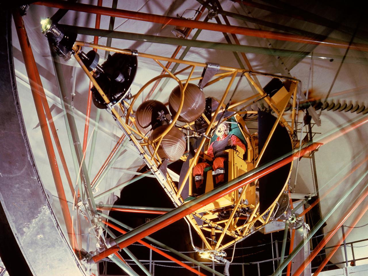
National Aeronautics and Space Administration (NASA) pilot Joe Algranti tests the Multi-Axis Space Test Inertia Facility (MASTIF) inside the Altitude Wind Tunnel while researcher Robert Miller looks on. The MASTIF was a three-axis rig with a pilot’s chair mounted in the center to train Project Mercury pilots to bring a spinning spacecraft under control. An astronaut was secured in a foam couch in the center of the rig. The rig then spun on three axes from 2 to 50 rotations per minute. Small nitrogen gas thrusters were used by the astronauts to bring the MASTIF under control. The device was originally designed in early 1959 without the chair and controllers. It was used by Lewis researchers to determine if the Lewis-designed autopilot system could rectify the capsule’s attitude following separation. If the control system failed to work properly, the heatshield would be out of place and the spacecraft would burn up during reentry. The system was flight tested during the September 1959 launch of the Lewis-assembled Big Joe capsule. The MASTIF was adapted in late 1959 for the astronaut training. NASA engineers added a pilot’s chair, a hand controller, and an instrument display to the MASTIF in order familiarize the astronauts with the sensations of an out-of-control spacecraft. NASA Lewis researcher James Useller and Algranti perfected and calibrated the MASTIF in the fall of 1959. In February and March 1960, the seven Project Mercury astronauts traveled to Cleveland to train on the MASTIF.
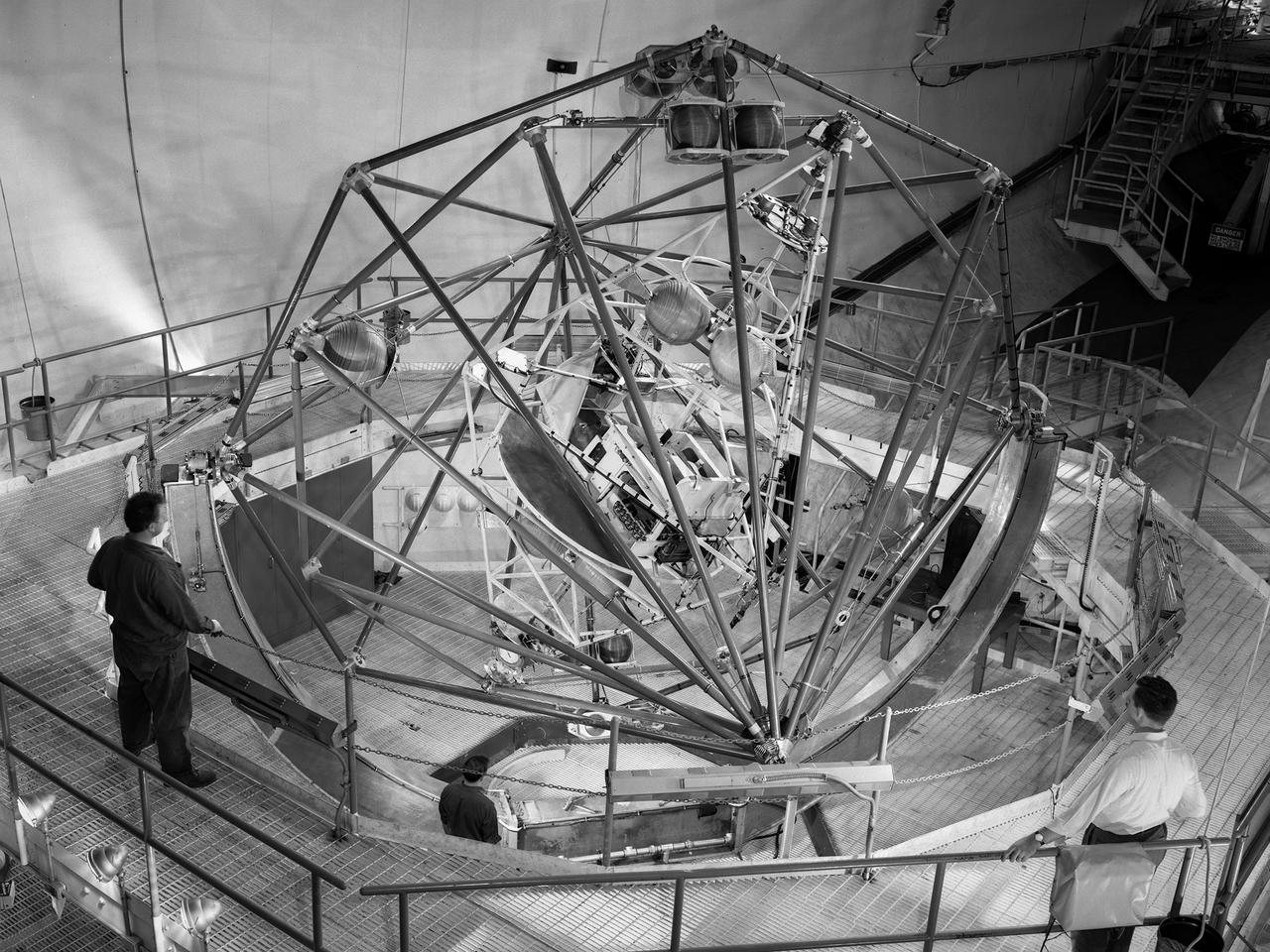
The Multi-Axis Space Test Inertial Facility (MASTIF) in the Altitude Wind Tunnel at the National Aeronautics and Space Administration (NASA) Lewis Research Center. Although the Mercury astronaut training and mission planning were handled by the Space Task Group at Langley Research Center, NASA Lewis played an important role in the program, beginning with the Big Joe launch. Big Joe was a singular attempt early in the program to use a full-scale Atlas booster and simulate the reentry of a mockup Mercury capsule without actually placing it in orbit. A unique three-axis gimbal rig was built inside Lewis’ Altitude Wind Tunnel to test Big Joe’s attitude controls. The control system was vital since the capsule would burn up on reentry if it were not positioned correctly. The mission was intended to assess the performance of the Atlas booster, the reliability of the capsule’s attitude control system and beryllium heat shield, and the capsule recovery process. The September 9, 1959 launch was a success for the control system and heatshield. Only a problem with the Atlas booster kept the mission from being a perfect success. The MASTIF was modified in late 1959 to train Project Mercury pilots to bring a spinning spacecraft under control. An astronaut was secured in a foam couch in the center of the rig. The rig then spun on three axes from 2 to 50 rotations per minute. Small nitrogen gas thrusters were used by the astronauts to bring the MASTIF under control.
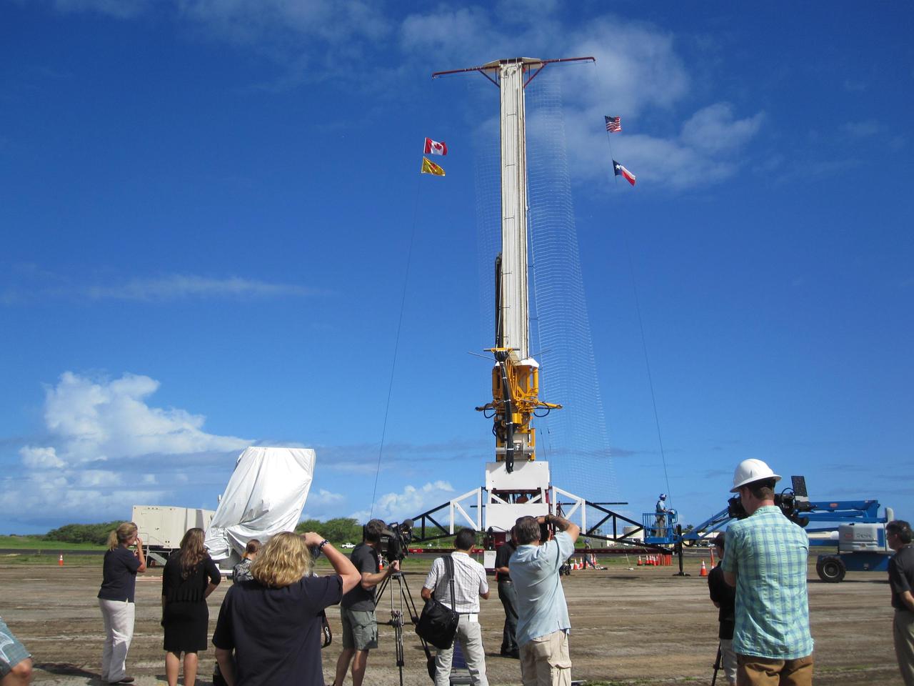
This image shows the tower from which the test vehicle for NASA Low-Density Supersonic Decelerator LDSD will hang before a balloon lifts it to high altitudes.
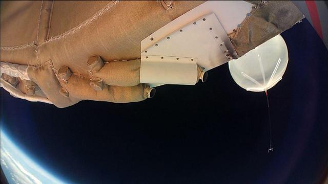
Moments into its powered flight, NASALow-density Supersonic Decelerator LDSD test vehicle captured this image of the balloon which carried it to high altitudes.
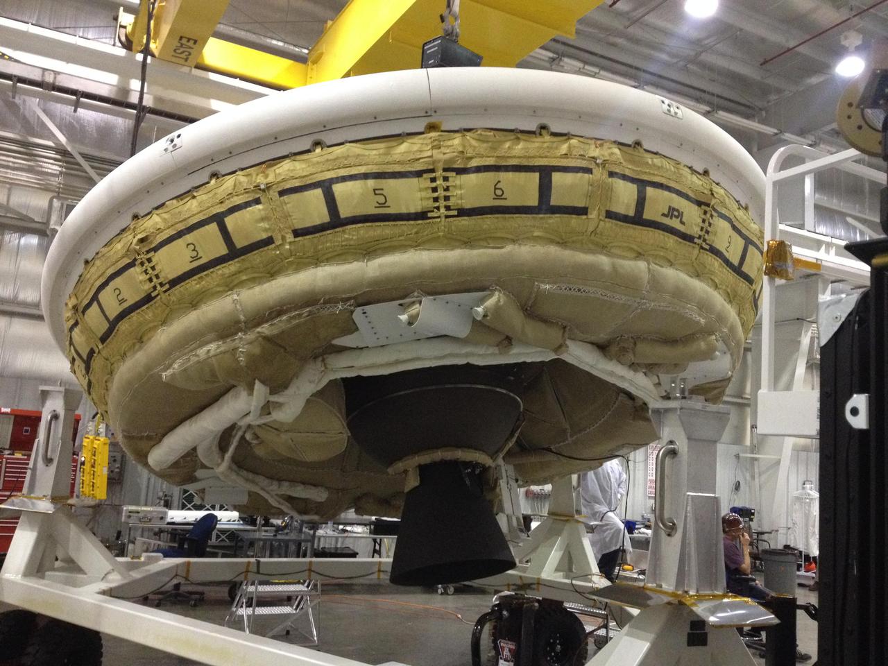
NASA Low-Density Supersonic Decelerator project, will test an inflatable decelerator and a parachute at high altitudes and speeds over the Pacific Missile Range this June.

Rocket engine propellant tanks and cell dome top the A-3 Test Stand under construction at Stennis Space Center. The stand will test next-generation rocket engines that could carry humans beyond low-Earth orbit into deep space once more.
Construction continues on NASA's A-3 Test Stand at Stennis Space Center. The stand is the first large test structure built at the south Mississippi facility since the 1960s.
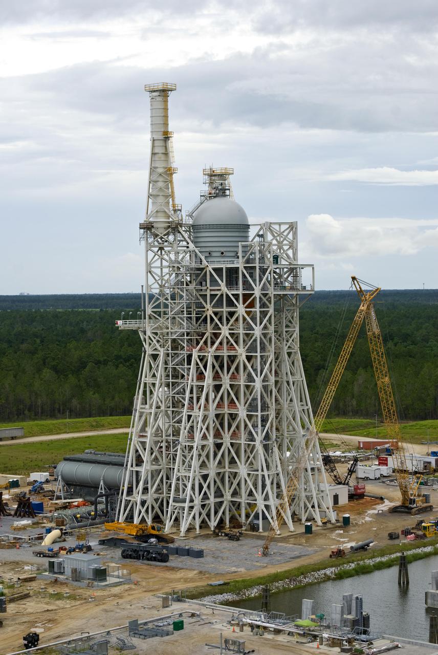
Rocket engine propellant tanks and cell dome top the A-3 Test Stand under construction at Stennis Space Center. The stand will test next-generation rocket engines that could carry humans beyond low-Earth orbit into deep space once more.
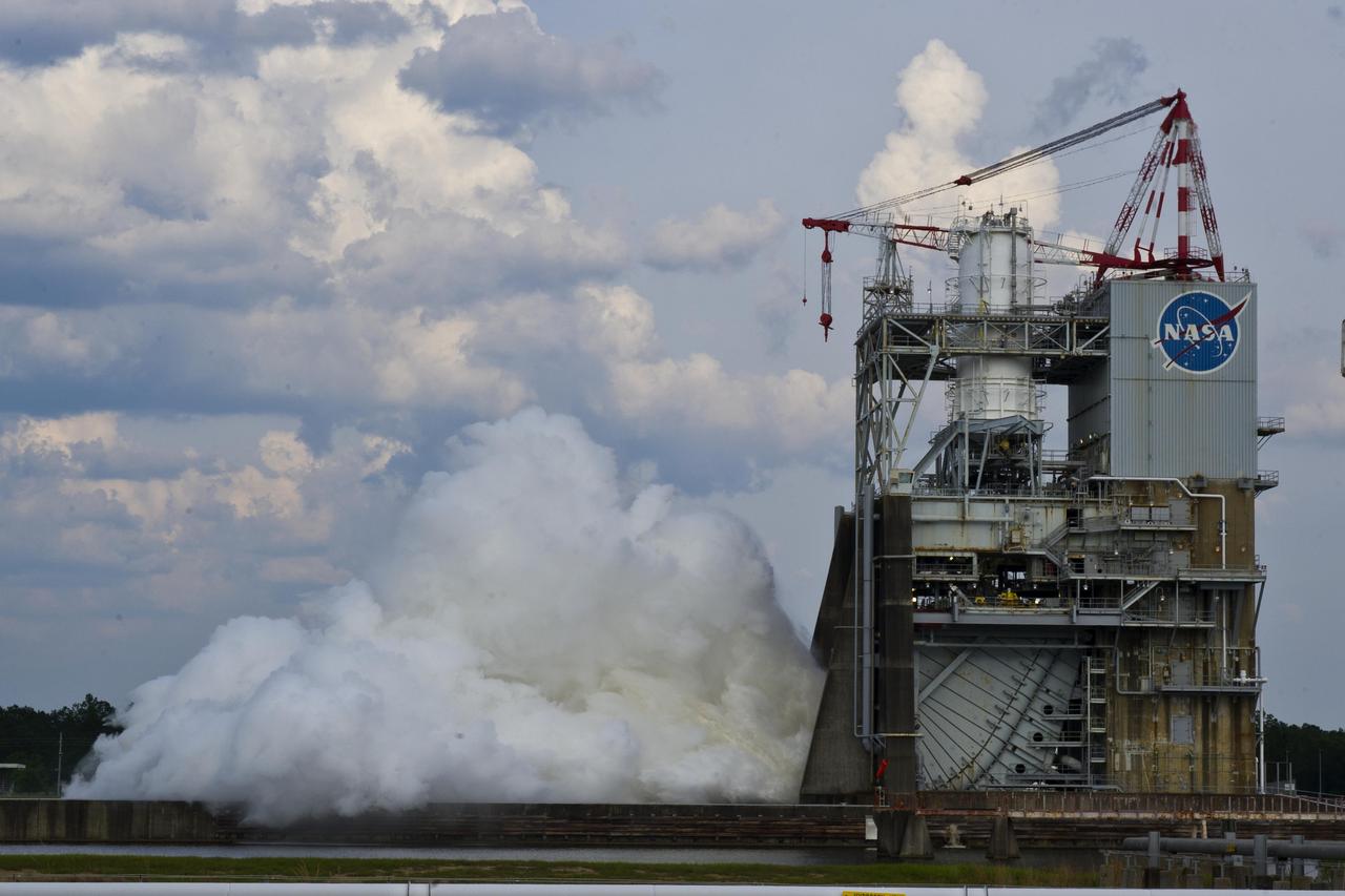
NASA conducted a successful seven-second test of the next-generation J-2X rocket engine on the A-2 Test Stand at Stennis Space Center on May 16, 2012. The J-2X is being developed for NASA by Pratt & Whitney Rocketdyne.
Stennis Space Center employees have installed liquid oxygen and liquid hydrogen tanks atop the A-3 Test Stand, raising the structure to its full 300-foot height. The stand is being built to test next-generation rocket engines that could carry humans beyond low-Earth orbit into deep space. The A-3 Test Stand is scheduled for completion and activation in 2013.
Construction on the new A-3 Test Stand continues at NASA's Stennis Space Center. The stand is the first large test structure built at the NASA facility since the 1960s.
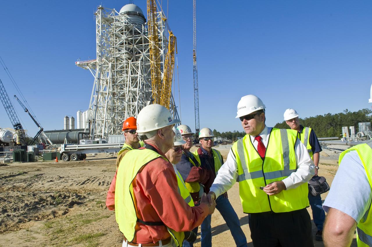
Stennis Space Center Director Patrick Scheuermann presents center director coins to employees following the 'topping out' of the A-3 Test Stand with placement of test cell dome on April 13. The stand is the first large test structure built at Stennis since the 1960s.

Construction on the new A-3 Test Stand continues at NASA's Stennis Space Center. The stand is the first large test structure built at the NASA facility since the 1960s.
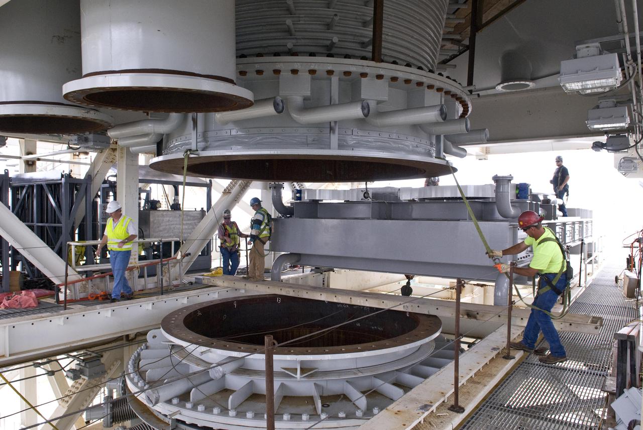
Stennis Space Center employees continue work on the A-3 Test Stand test cell. The stand is being built to test next-generation rocket engines that could carry humans beyond low-Earth orbit into deep space.
The Gamma-Ray Imager/Polarimeter for Solar flares (GRIPS) instrument is installed in the B-2 vacuum chamber for a full-instrument thermal-vacuum test in 2015. The GRIPS telescope was launched via balloon in January 2016 on a high-altitude flight over Antarctica to study the acceleration and transport of solar flare particles.
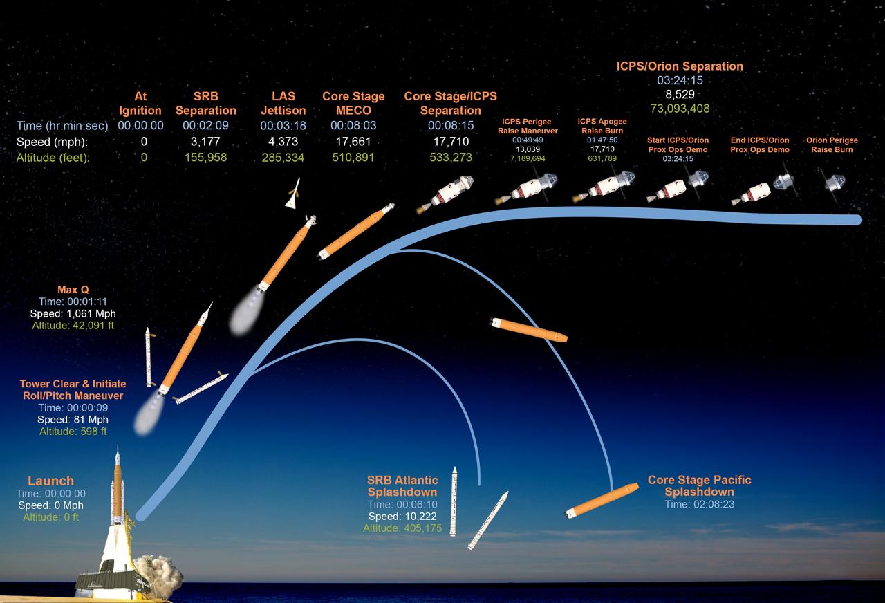
This graphic shows the time, speed, and altitude of key events from launch of the SLS (Space Launch System) rocket and Orion spacecraft and ascent to space, through Orion's perigee raise burn during the Artemis II test flight.
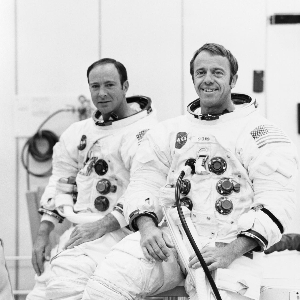
S70-19764 (18 Sept. 1970) --- Astronauts Alan B. Shepard Jr. (right), commander, and Edgar D. Mitchell, lunar module pilot, are suited up for a manned altitude run in the Apollo 14 Lunar Module. The manned run in a vacuum chamber of the Manned Spacecraft Operations Building was conducted to validate the LM's communications and guidance and navigation systems. Apollo 14 is scheduled for launch from Cape Kennedy on Jan. 31, 1971, on a lunar exploration mission which is to carry Shepard and Mitchell down to the moon's rugged Fra Maura highlands region. Astronaut Stuart A. Roosa, command module pilot, will remain with the Apollo 14 Command and Service Modules in lunar orbit while the other two astronauts explore the moon.
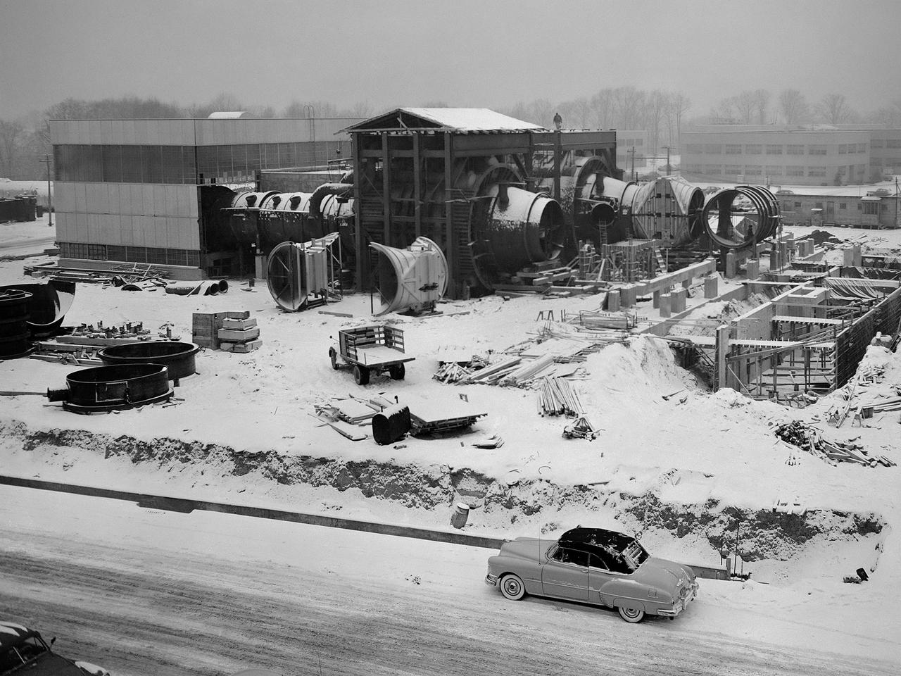
Construction of the Propulsion Systems Laboratory No. 1 and 2 at the National Advisory Committee for Aeronautics (NACA) Lewis Flight Propulsion Laboratory. When it began operation in late 1952, the Propulsion Systems Laboratory was the NACA’s most powerful facility for testing full-scale engines at simulated flight altitudes. The facility contained two altitude simulating test chambers which were a technological combination of the static sea-level test stands and the complex Altitude Wind Tunnel, which recreated actual flight conditions on a larger scale. NACA Lewis began designing the new facility in 1947 as part of a comprehensive plan to improve the altitude testing capabilities across the lab. The exhaust, refrigeration, and combustion air systems from all the major test facilities were linked. In this way, different facilities could be used to complement the capabilities of one another. Propulsion Systems Laboratory construction began in late summer 1949 with the installation of an overhead exhaust pipe connecting the facility to the Altitude Wind Tunnel and Engine Research Building. The large test section pieces arriving in early 1951, when this photograph was taken. The two primary coolers for the altitude exhaust are in place within the framework near the center of the photograph.
S68-38051 (29 June 1968) --- Astronaut Russell L. Schweickart suits up to participate in an altitude verification test of the Apollo Portable Life Support System flight unit in Crew Systems Division's 8-ft altitude chamber in Building 7.
The A-3 Test Stand under construction at Stennis Space Center is set for completion and activation in 2013. It will allow operators to conduct simulated high-altitude testing on the next-generation J-2X rocket engine.

The A-3 Test Stand under construction at Stennis Space Center is set for completion and activation in 2013. It will allow operators to conduct simulated high-altitude testing on the next-generation J-2X rocket engine.
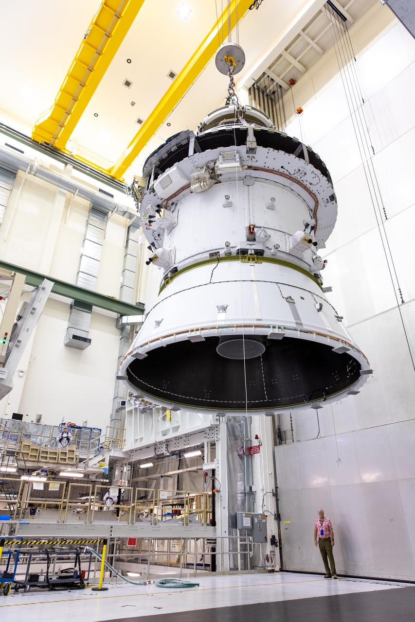
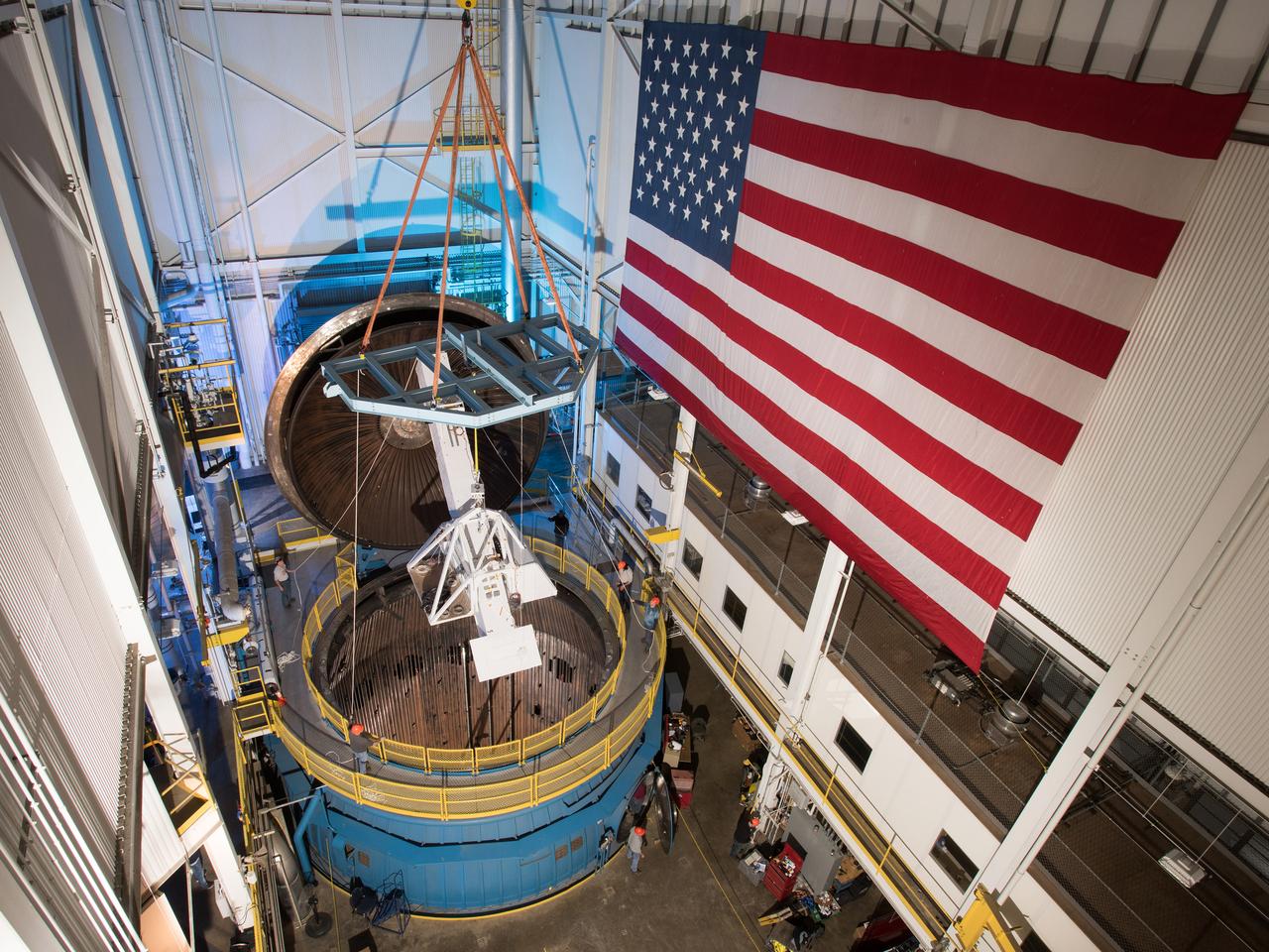
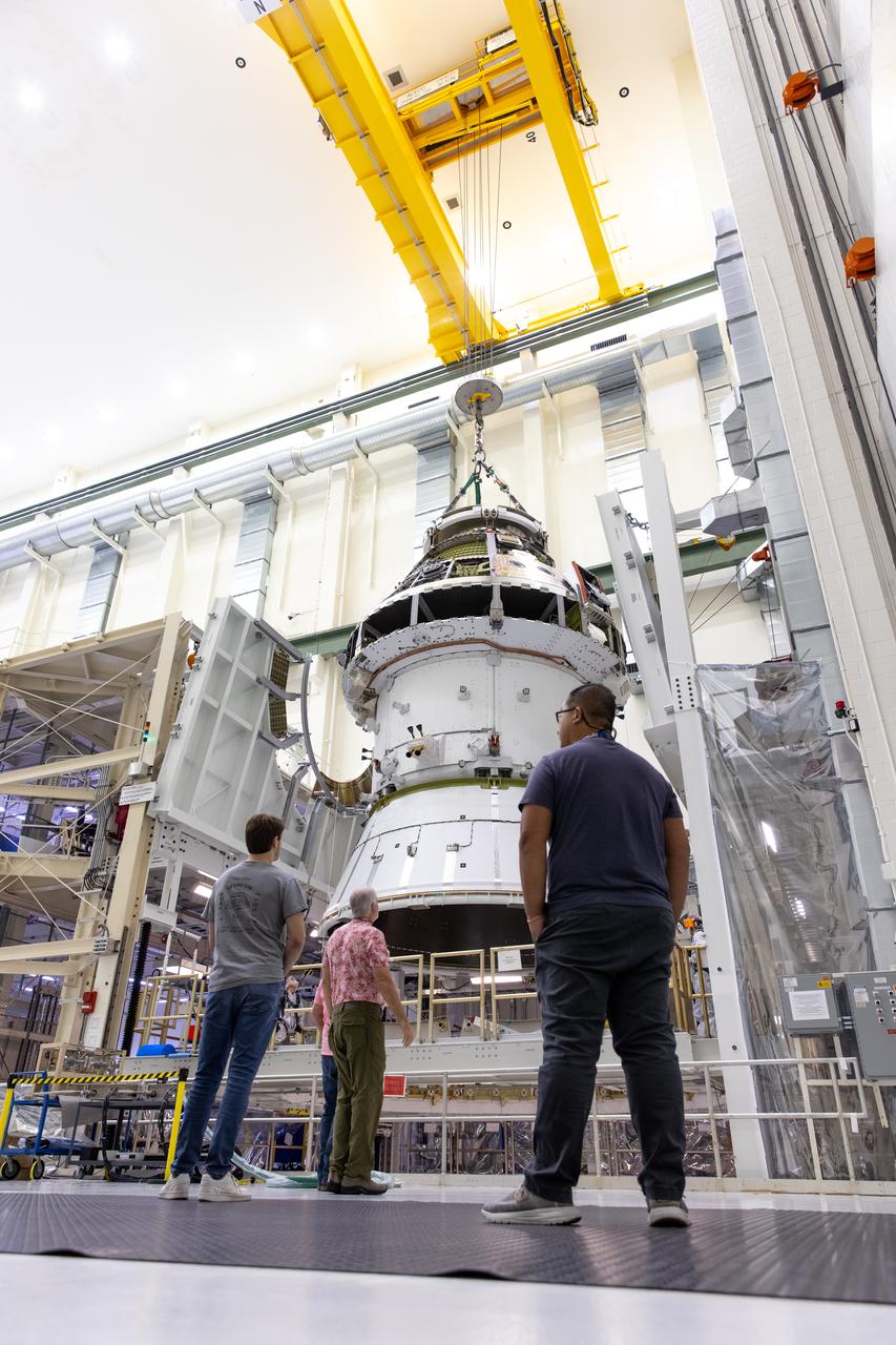
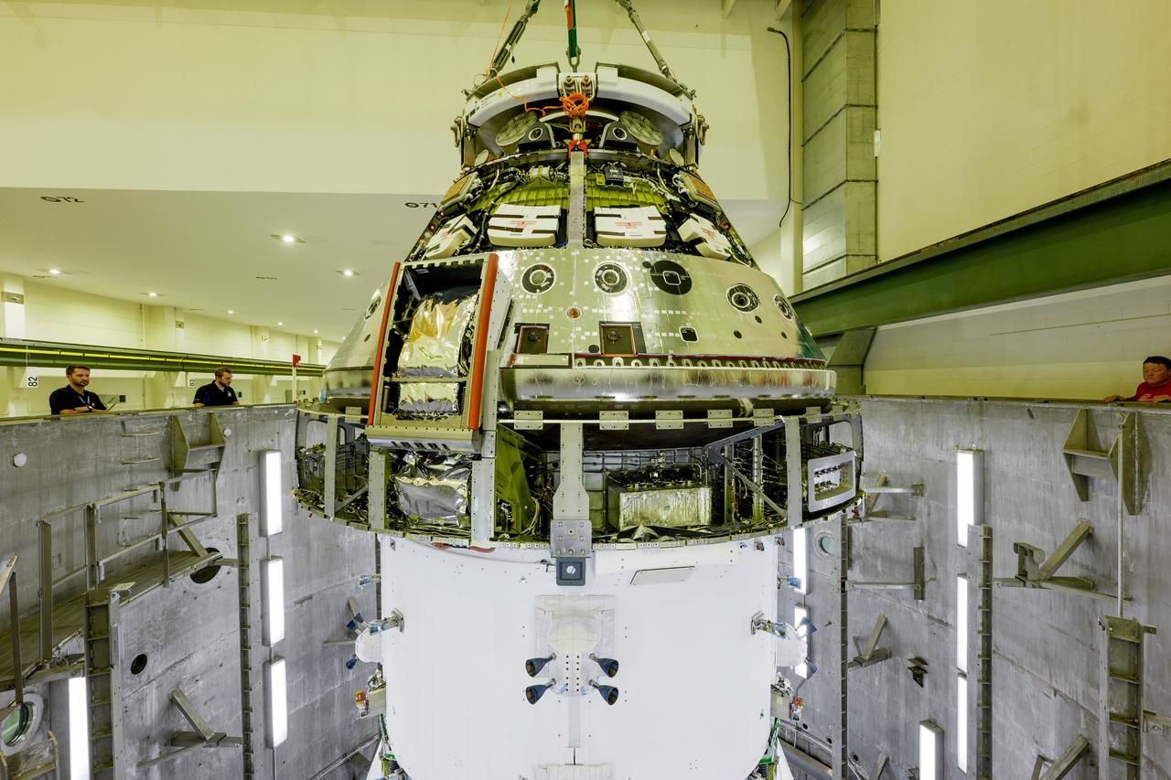
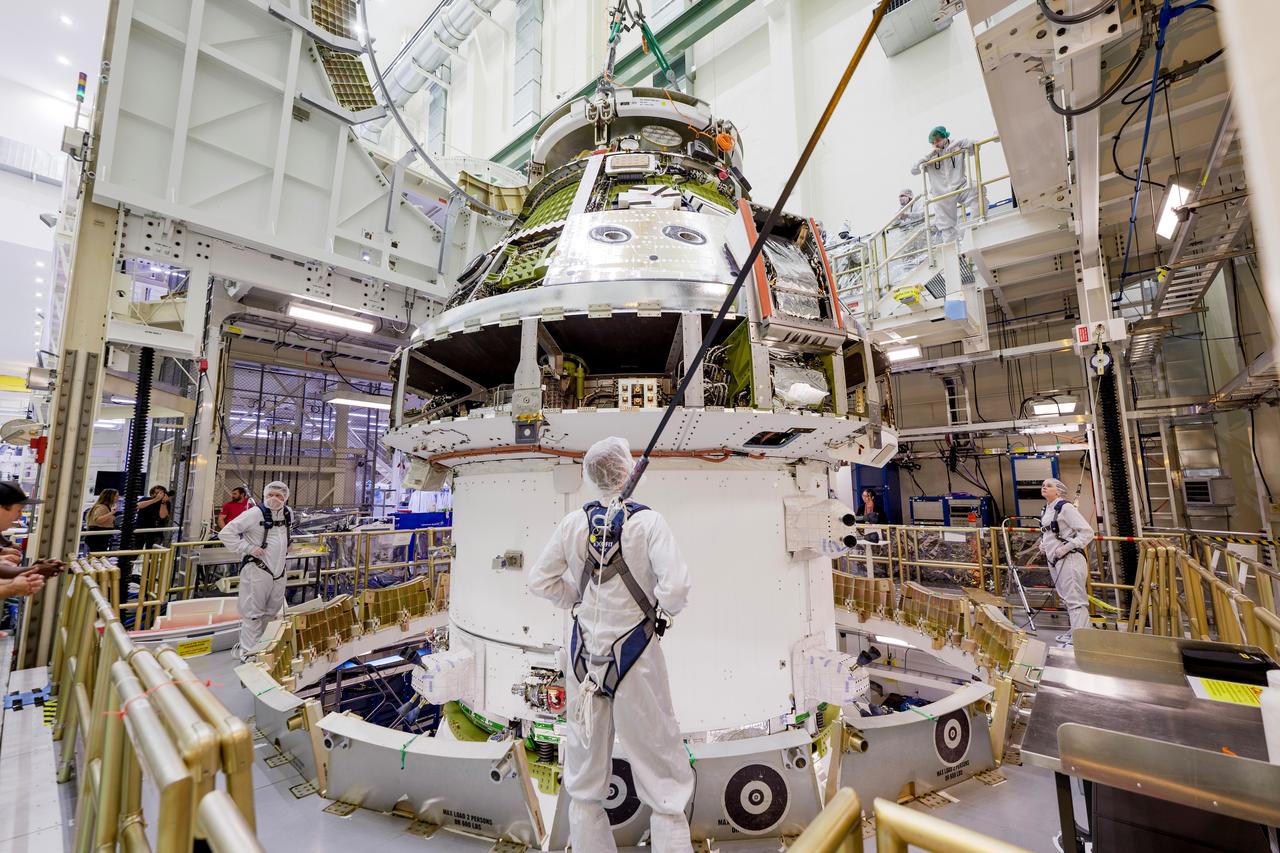
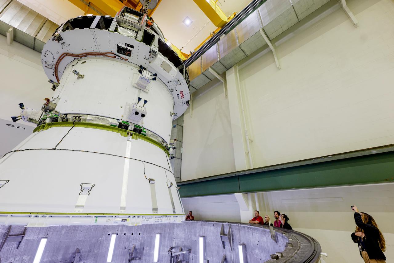
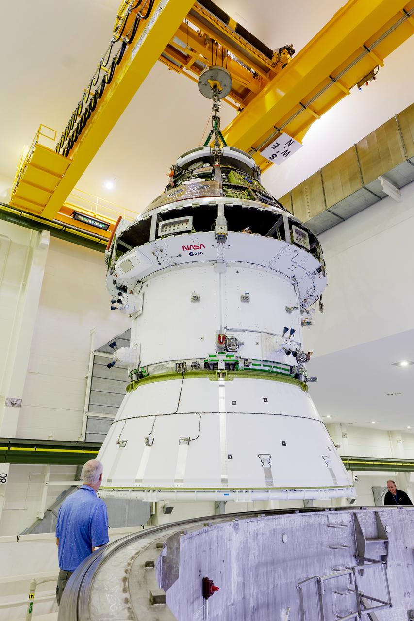
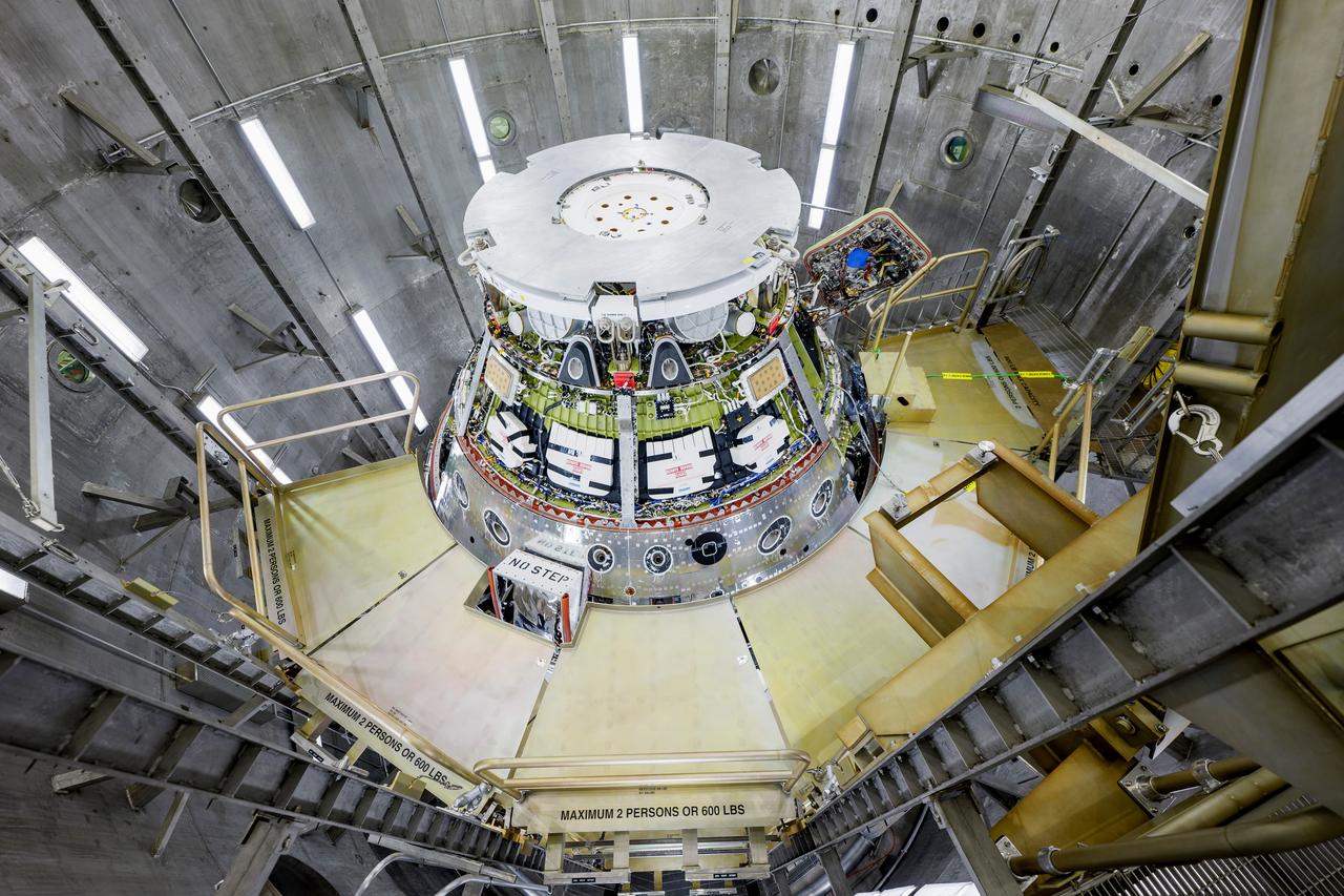
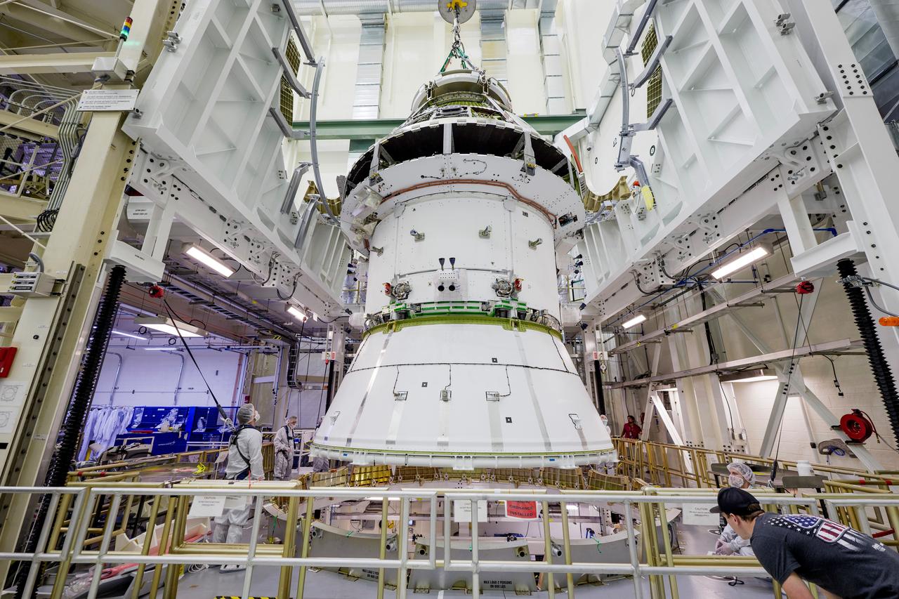
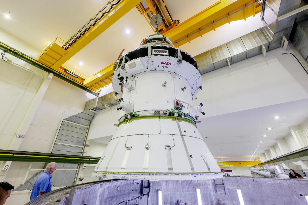
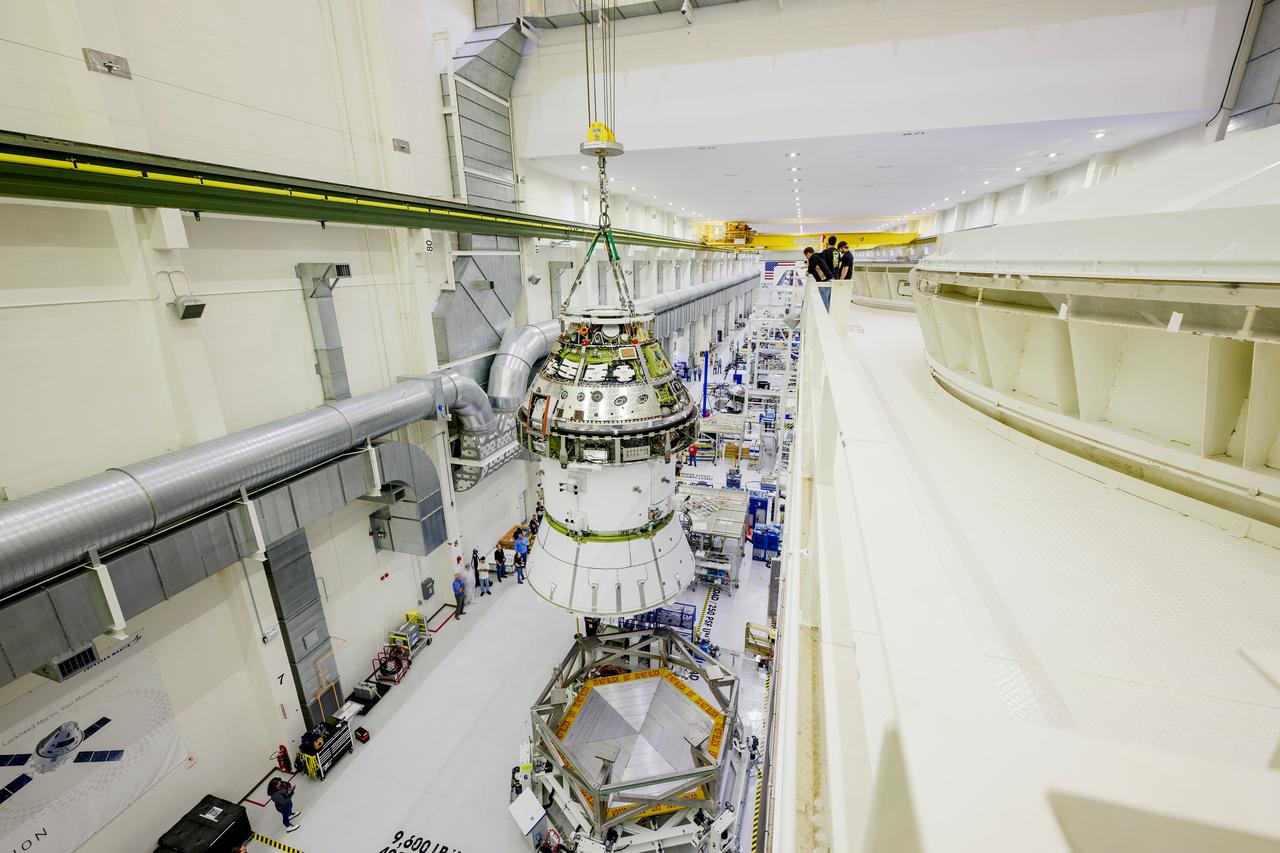
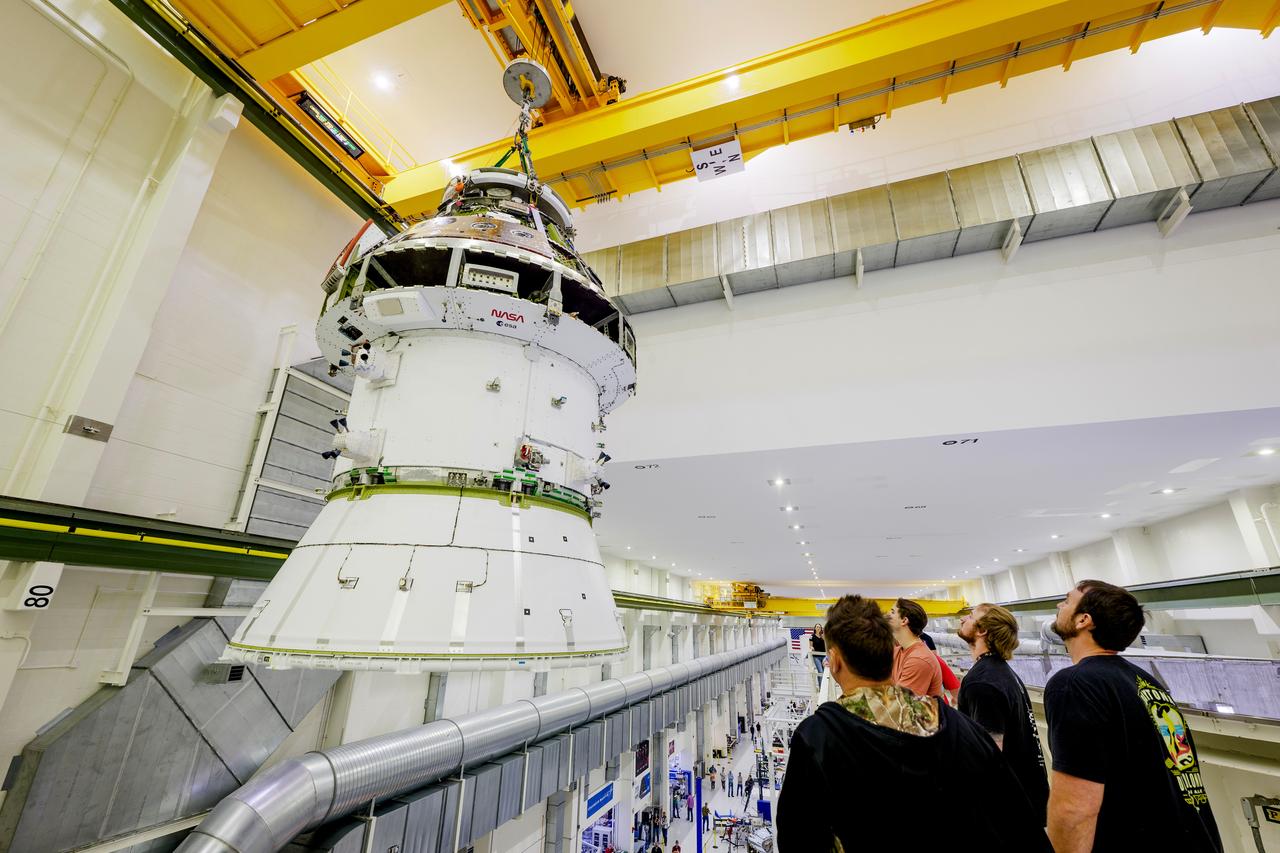
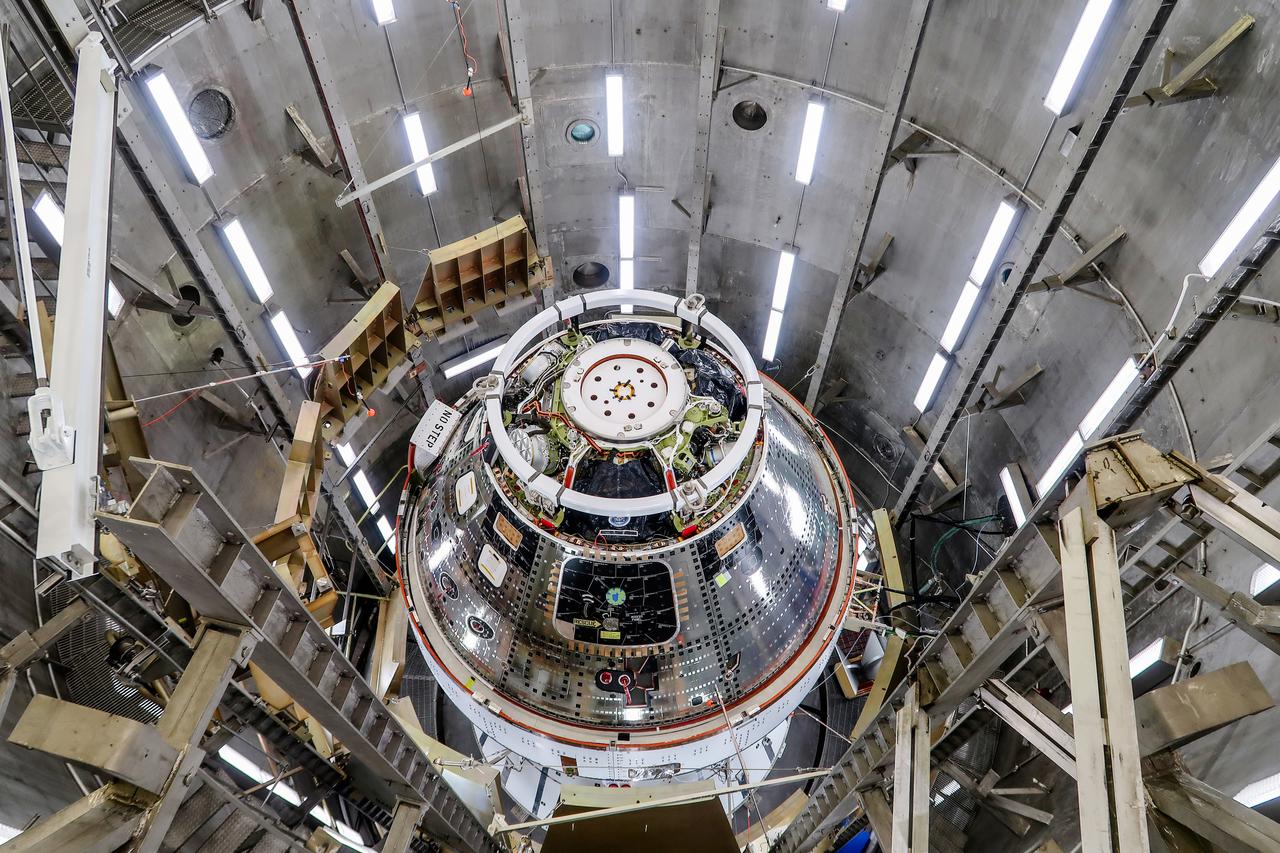
A massive crane lifts NASA’s Orion spacecraft out of the Final Assembly and System Testing cell and moves it to the altitude chamber to complete further testing on Thursday, Nov. 7, 2024, inside the Neil A. Armstrong Operations and Checkout building at NASA's Kennedy Space Center in Florida. The altitude chamber simulates deep space vacuum conditions, and the testing will provide additional data to augment data gained during testing earlier this summer. The Orion spacecraft will carry NASA astronauts Victor Glover, Christina Koch, and Reid Wiseman, as well as CSA (Canadian Space Agency) astronaut Jeremy Hansen, on a 10-day journey around the Moon and back for the Artemis II test flight.
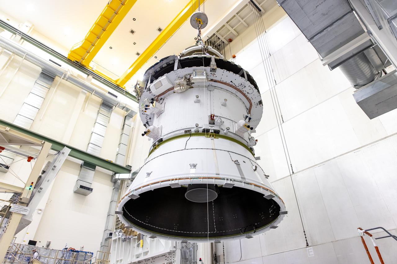
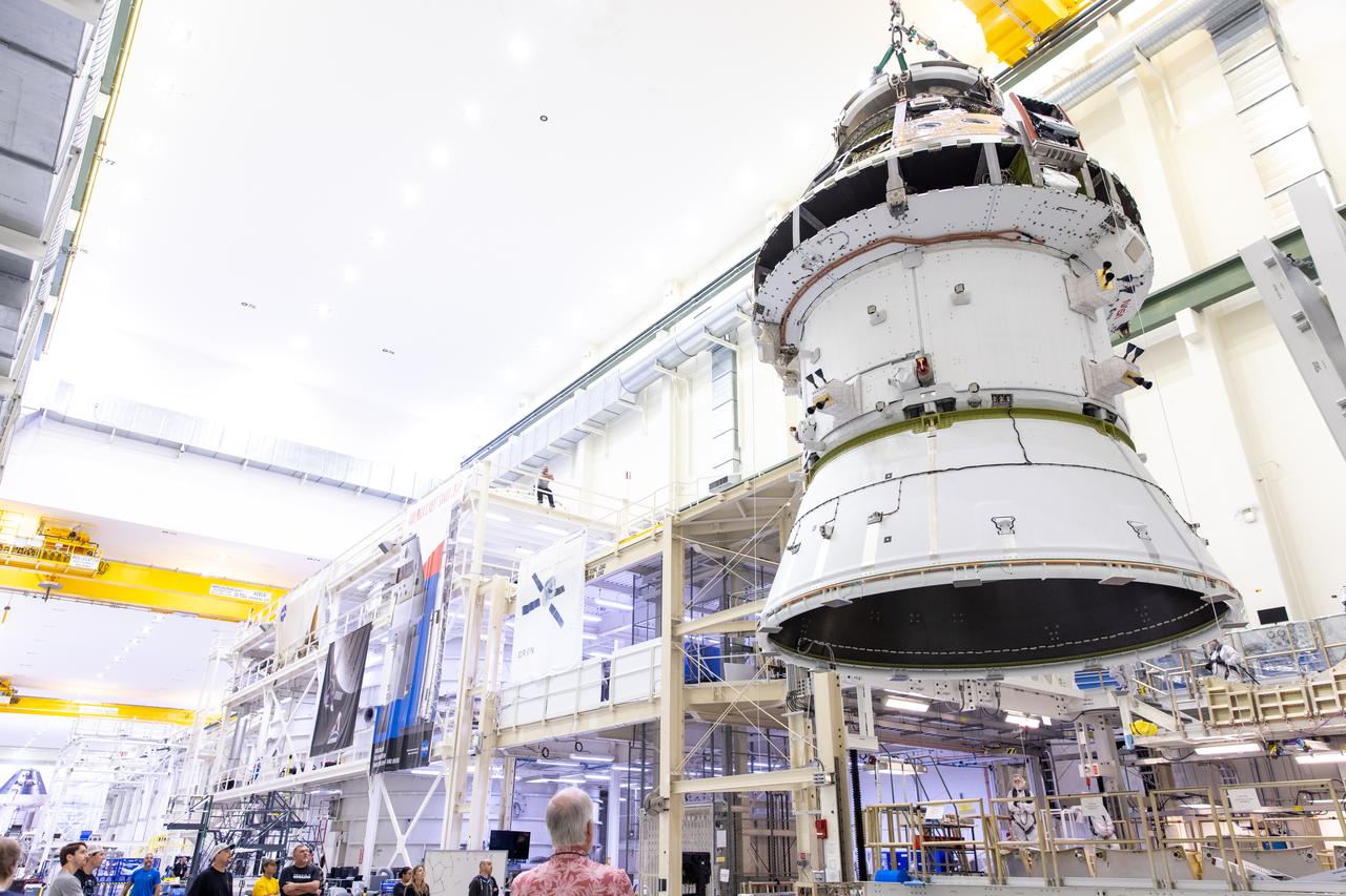
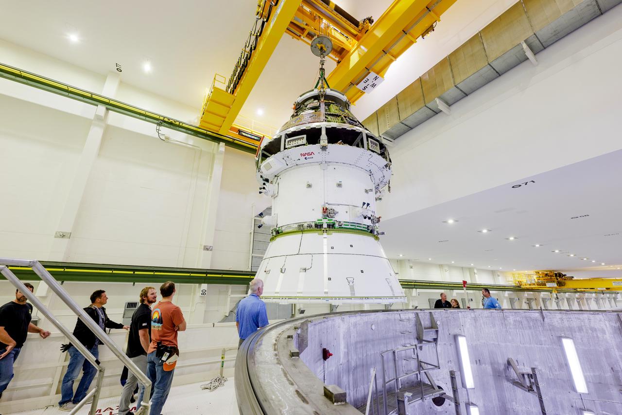
A massive crane lifts NASA’s Orion spacecraft out of the Final Assembly and System Testing cell and moves it to the altitude chamber to complete further testing on Thursday, Nov. 7, 2024, inside the Neil A. Armstrong Operations and Checkout building at NASA's Kennedy Space Center in Florida. The altitude chamber simulates deep space vacuum conditions, and the testing will provide additional data to augment data gained during testing earlier this summer. The Orion spacecraft will carry NASA astronauts Victor Glover, Christina Koch, and Reid Wiseman, as well as CSA (Canadian Space Agency) astronaut Jeremy Hansen, on a 10-day journey around the Moon and back for the Artemis II test flight.
A massive crane lifts NASA’s Orion spacecraft out of the Final Assembly and System Testing cell and moves it to the altitude chamber to complete further testing on Thursday, Nov. 7, 2024, inside the Neil A. Armstrong Operations and Checkout building at NASA's Kennedy Space Center in Florida. The altitude chamber simulates deep space vacuum conditions, and the testing will provide additional data to augment data gained during testing earlier this summer. The Orion spacecraft will carry NASA astronauts Victor Glover, Christina Koch, and Reid Wiseman, as well as CSA (Canadian Space Agency) astronaut Jeremy Hansen, on a 10-day journey around the Moon and back for the Artemis II test flight.
A massive crane lifts NASA’s Orion spacecraft out of the Final Assembly and System Testing cell and moves it to the altitude chamber to complete further testing on Thursday, Nov. 7, 2024, inside the Neil A. Armstrong Operations and Checkout building at NASA's Kennedy Space Center in Florida. The altitude chamber simulates deep space vacuum conditions, and the testing will provide additional data to augment data gained during testing earlier this summer. The Orion spacecraft will carry NASA astronauts Victor Glover, Christina Koch, and Reid Wiseman, as well as CSA (Canadian Space Agency) astronaut Jeremy Hansen, on a 10-day journey around the Moon and back for the Artemis II test flight.

A Wright Aeronautical XRJ47-W-5 ramjet installed in a test chamber of the National Advisory Committee for Aeronautics’ (NACA) new Propulsion Systems Laboratory at the Lewis Flight Propulsion Laboratory. Construction of the facility had only recently been completed, and NACA engineers were still testing the various operating systems. The Propulsion Systems Laboratory was the NACA’s most powerful facility for testing full-scale engines in simulated flight altitudes. It contained two 14-foot diameter and 100-foot-long altitude chambers that ran parallel to one another with a control room in between. The engine being tested was installed inside the test section of one of the chambers, seen in this photograph. Extensive instrumentation was fitted onto the engine prior to the test. Once the chamber was sealed, the altitude conditions were introduced, and the engine was ignited. Operators in the control room could run the engine at the various speeds and adjust the altitude conditions to the desired levels. The engine’s exhaust was ejected into the cooling equipment. Two 48-inch diameter XRJ47-W-5 ramjets were used to power the North American Aviation Navaho Missile. The Navaho was a winged missile that was intended to travel up to 3000 miles carrying a nuclear warhead. It was launched using rocket booster engines that were ejected after the missile’s ramjet engines were ignited.
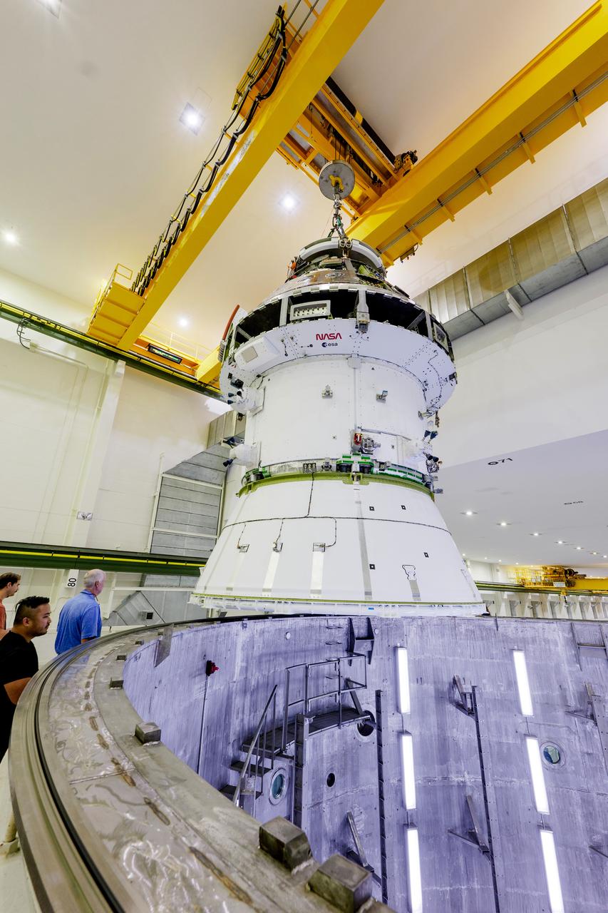
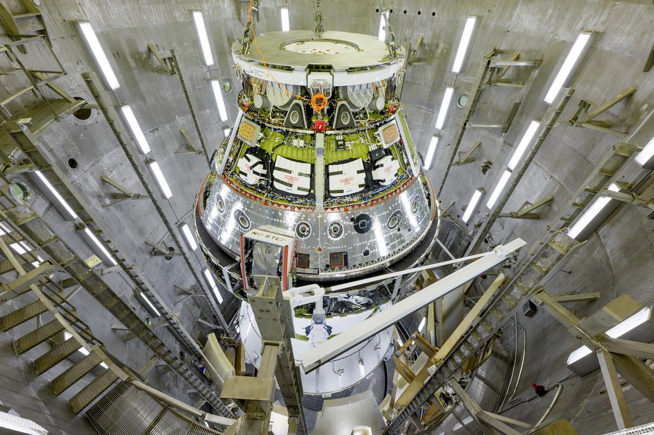
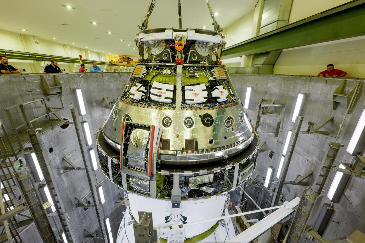
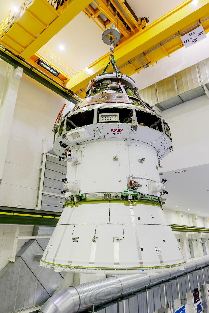
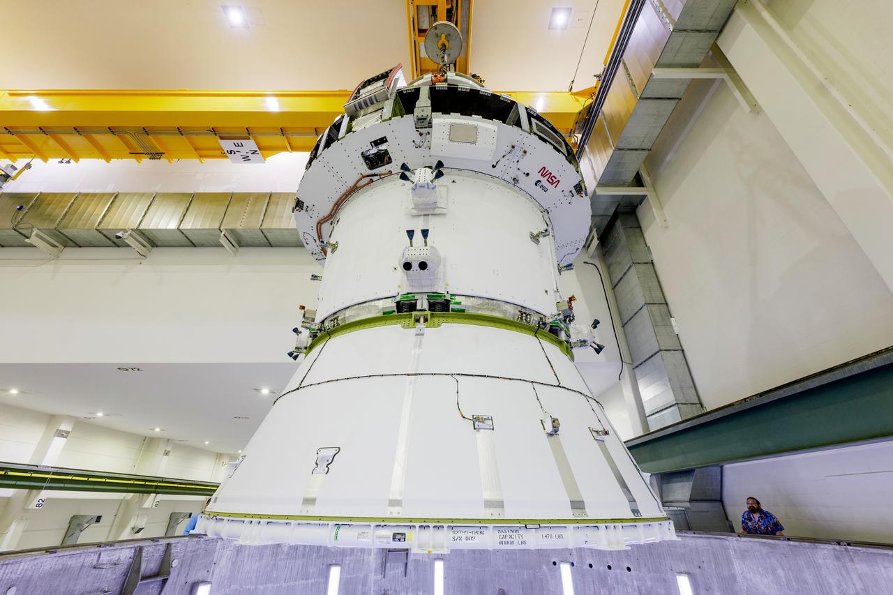
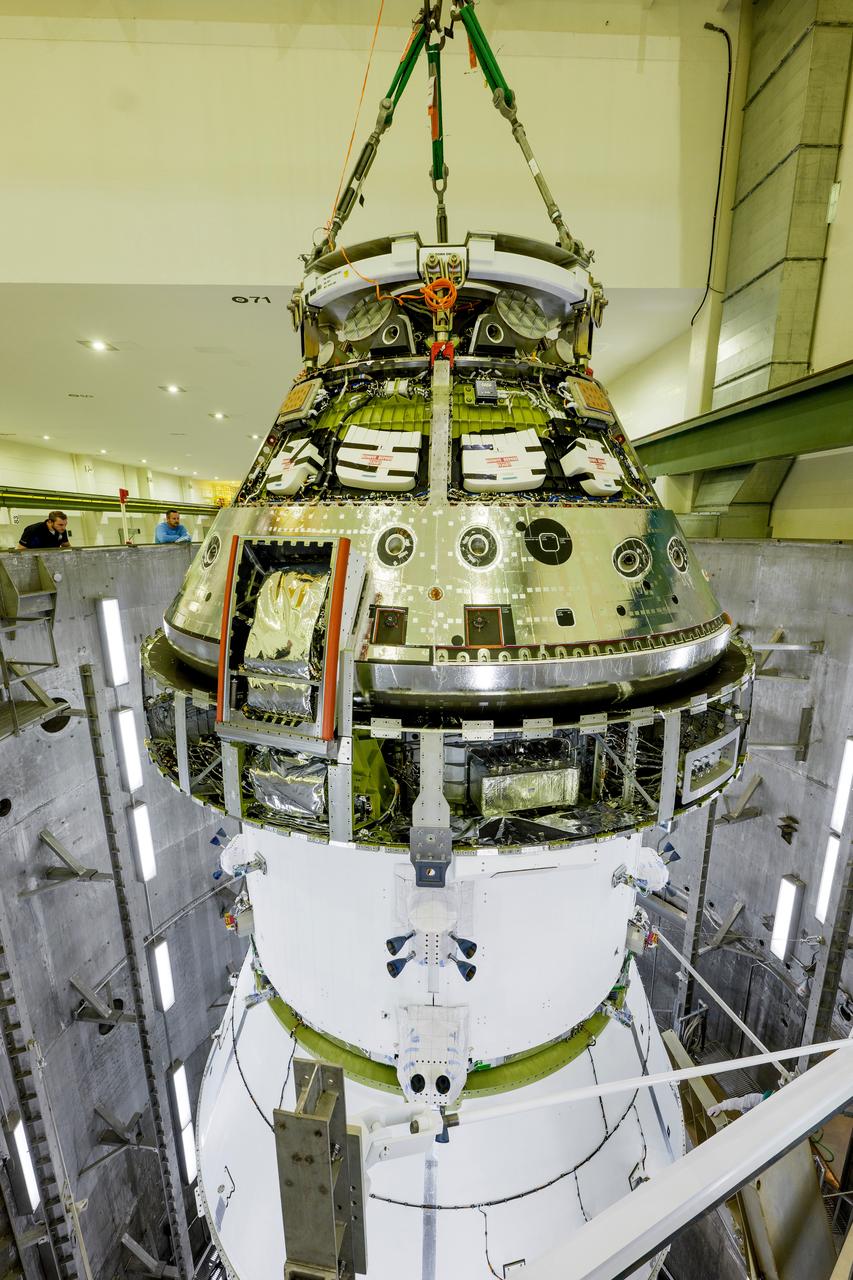
The Artemis II Orion spacecraft is lifted from the Final Assembly and Testing (FAST) Cell and placed in the west altitude chamber inside the Operations and Checkout Building at NASA’S Kennedy Space Center in Florida on June 28, 2024. Inside the altitude chamber, the spacecraft underwent a series of tests simulating deep space vacuum conditions. Photo Credit: NASA / Rad Sinyak
The Artemis II Orion spacecraft is lifted from the Final Assembly and Testing (FAST) Cell and placed in the west altitude chamber inside the Operations and Checkout Building at NASA’S Kennedy Space Center in Florida on June 28, 2024. Inside the altitude chamber, the spacecraft underwent a series of tests simulating deep space vacuum conditions. Photo Credit: NASA / Rad Sinyak
The Artemis II Orion spacecraft is lifted from the Final Assembly and Testing (FAST) Cell and placed in the west altitude chamber inside the Operations and Checkout Building at NASA’S Kennedy Space Center in Florida on June 28, 2024. Inside the altitude chamber, the spacecraft underwent a series of tests simulating deep space vacuum conditions. Photo Credit: NASA / Rad Sinyak
The Artemis II Orion spacecraft is lifted from the Final Assembly and Testing (FAST) Cell and placed in the west altitude chamber inside the Operations and Checkout Building at NASA’S Kennedy Space Center in Florida on June 28, 2024. Inside the altitude chamber, the spacecraft underwent a series of tests simulating deep space vacuum conditions. Photo Credit: NASA / Rad Sinyak
The Artemis II Orion spacecraft is lifted from the Final Assembly and Testing (FAST) Cell and placed in the west altitude chamber inside the Operations and Checkout Building at NASA’S Kennedy Space Center in Florida on June 28, 2024. Inside the altitude chamber, the spacecraft underwent a series of tests simulating deep space vacuum conditions. Photo Credit: NASA / Rad Sinyak
The Artemis II Orion spacecraft is lifted from the Final Assembly and Testing (FAST) Cell and placed in the west altitude chamber inside the Operations and Checkout Building at NASA’S Kennedy Space Center in Florida on June 28, 2024. Inside the altitude chamber, the spacecraft underwent a series of tests simulating deep space vacuum conditions. Photo Credit: NASA / Rad Sinyak

The Artemis II Orion spacecraft is lifted from the Final Assembly and Testing (FAST) Cell and placed in the west altitude chamber inside the Operations and Checkout Building at NASA’S Kennedy Space Center in Florida on June 28, 2024. Inside the altitude chamber, the spacecraft underwent a series of tests simulating deep space vacuum conditions. Photo Credit: NASA / Rad Sinyak
The Artemis II Orion spacecraft is lifted from the Final Assembly and System Testing (FAST) Cell and placed in the west altitude chamber inside the Operations and Checkout Building at NASA’S Kennedy Space Center in Florida on June 28, 2024. Inside the altitude chamber, the spacecraft underwent a series of tests simulating deep space vacuum conditions. Photo Credit: NASA / Rad Sinyak
The Artemis II Orion spacecraft is lifted from the Final Assembly and System Testing (FAST) Cell and placed in the west altitude chamber inside the Operations and Checkout Building at NASA’S Kennedy Space Center in Florida on June 28, 2024. Inside the altitude chamber, the spacecraft underwent a series of tests simulating deep space vacuum conditions. Photo Credit: NASA / Rad Sinyak
The Artemis II Orion spacecraft is lifted from the Final Assembly and Testing (FAST) Cell and placed in the west altitude chamber inside the Operations and Checkout Building at NASA’S Kennedy Space Center in Florida on June 28, 2024. Inside the altitude chamber, the spacecraft underwent a series of tests simulating deep space vacuum conditions. Photo Credit: NASA / Rad Sinyak
The Artemis II Orion spacecraft is lifted from the Final Assembly and Testing (FAST) Cell and placed in the west altitude chamber inside the Operations and Checkout Building at NASA’S Kennedy Space Center in Florida on June 28, 2024. Inside the altitude chamber, the spacecraft underwent a series of tests simulating deep space vacuum conditions. Photo Credit: NASA / Rad Sinyak
The Artemis II Orion spacecraft is lifted from the Final Assembly and Testing (FAST) Cell and placed in the west altitude chamber inside the Operations and Checkout Building at NASA’S Kennedy Space Center in Florida on June 28, 2024. Inside the altitude chamber, the spacecraft underwent a series of tests simulating deep space vacuum conditions. Photo Credit: NASA / Rad Sinyak

The Artemis II Orion spacecraft is lifted from the Final Assembly and System Testing (FAST) Cell and placed in the west altitude chamber inside the Operations and Checkout Building at NASA’S Kennedy Space Center in Florida on June 28, 2024. Inside the altitude chamber, the spacecraft underwent a series of tests simulating deep space vacuum conditions. Photo Credit: NASA / Rad Sinyak
The Artemis II Orion spacecraft is lifted from the Final Assembly and Testing (FAST) Cell and placed in the west altitude chamber inside the Operations and Checkout Building at NASA’S Kennedy Space Center in Florida on June 28, 2024. Inside the altitude chamber, the spacecraft underwent a series of tests simulating deep space vacuum conditions. Photo Credit: NASA / Rad Sinyak
The Artemis II Orion spacecraft is lifted from the Final Assembly and Testing (FAST) Cell and placed in the west altitude chamber inside the Operations and Checkout Building at NASA’S Kennedy Space Center in Florida on June 28, 2024. Inside the altitude chamber, the spacecraft underwent a series of tests simulating deep space vacuum conditions. Photo Credit: NASA / Rad Sinyak
The Artemis II Orion spacecraft is lifted from the Final Assembly and Testing (FAST) Cell and placed in the west altitude chamber inside the Operations and Checkout Building at NASA’S Kennedy Space Center in Florida on June 28, 2024. Inside the altitude chamber, the spacecraft underwent a series of tests simulating deep space vacuum conditions. Photo Credit: NASA / Rad Sinyak
The Artemis II Orion spacecraft is lifted from the Final Assembly and Testing (FAST) Cell and placed in the west altitude chamber inside the Operations and Checkout Building at NASA’S Kennedy Space Center in Florida on June 28, 2024. Inside the altitude chamber, the spacecraft underwent a series of tests simulating deep space vacuum conditions. Photo Credit: NASA / Rad Sinyak
The Artemis II Orion spacecraft is lifted from the Final Assembly and System Testing (FAST) Cell and placed in the west altitude chamber inside the Operations and Checkout Building at NASA’S Kennedy Space Center in Florida on June 28, 2024. Inside the altitude chamber, the spacecraft underwent a series of tests simulating deep space vacuum conditions. Photo Credit: NASA / Rad Sinyak
The Artemis II Orion spacecraft is lifted from the Final Assembly and Testing (FAST) Cell and placed in the west altitude chamber inside the Operations and Checkout Building at NASA’S Kennedy Space Center in Florida on June 28, 2024. Inside the altitude chamber, the spacecraft underwent a series of tests simulating deep space vacuum conditions. Photo Credit: NASA / Rad Sinyak
The Artemis II Orion spacecraft is lifted from the Final Assembly and Testing (FAST) Cell and placed in the west altitude chamber inside the Operations and Checkout Building at NASA’S Kennedy Space Center in Florida on June 28, 2024. Inside the altitude chamber, the spacecraft underwent a series of tests simulating deep space vacuum conditions. Photo Credit: NASA / Rad Sinyak
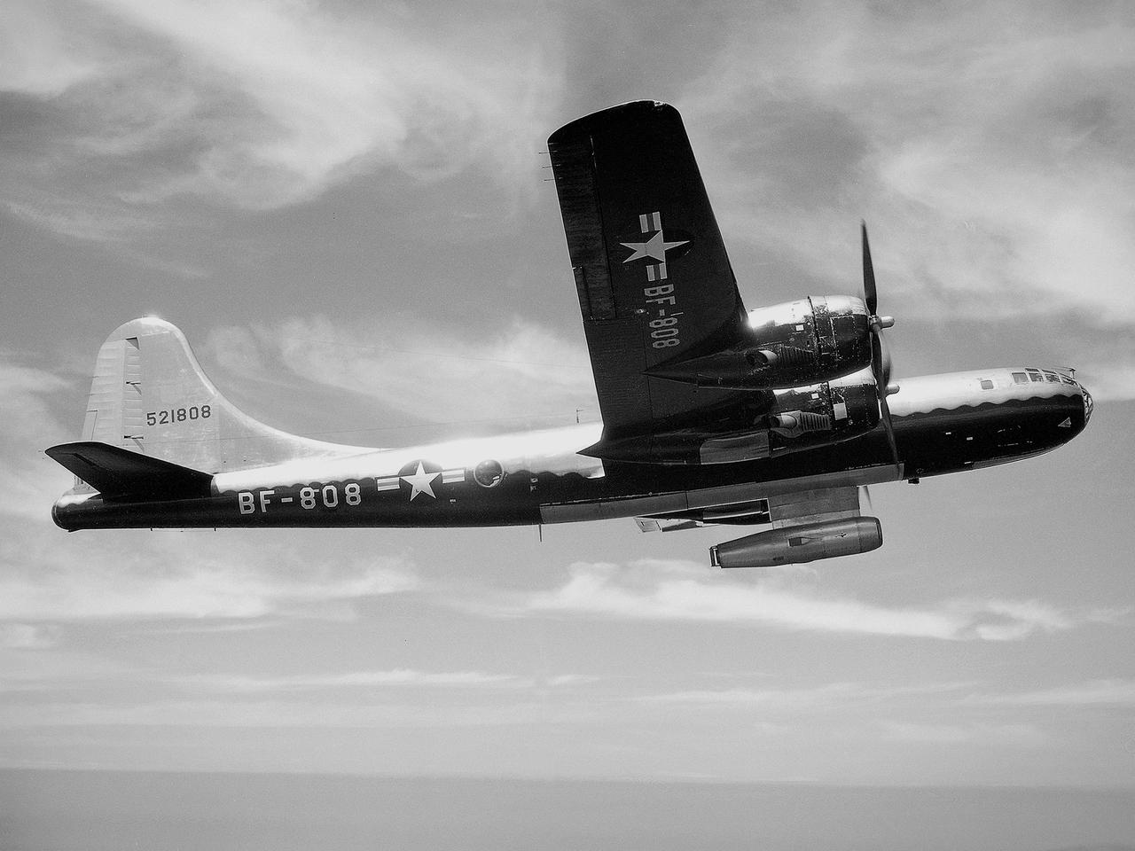
The NACA’s Lewis Flight Propulsion Laboratory used a Boeing B‒29 Superfortress as a testbed for ramjet investigations in the late 1940s. Lewis researchers conducted a wide variety of studies on ramjets to determine basic the operational data necessary to design missiles. Extensive wind tunnel and test stand studies were augmented by actual flight tests. Lewis engineers modified this B‒29 so that the ramjet could be stored in the bomb bay. Once the aircraft reached the desired altitude and speed, a mechanical arm suspended the ramjet 52 inches below the bomb bay. The ramjet’s angle-of-attack could be independently adjusted, and a periscope permitted a view of the test article from inside the aircraft. Researchers took measurements in free-stream conditions at speeds up to Mach 0.51 and at altitudes ranging from 5,000 to 30,000 feet. They then shut the ramjet down and retracted it into the aircraft. The researchers first determined that 14,000 feet was the maximum altitude at which the engine could be ignited by spark. They used flares to start the engine at altitudes up to 30,000 feet. They were able to determine maximum combustion efficiencies, response time to changes in fuel flow, and minimum fuel-air ratios. Overall the ramjet operated well at all speeds and altitudes.
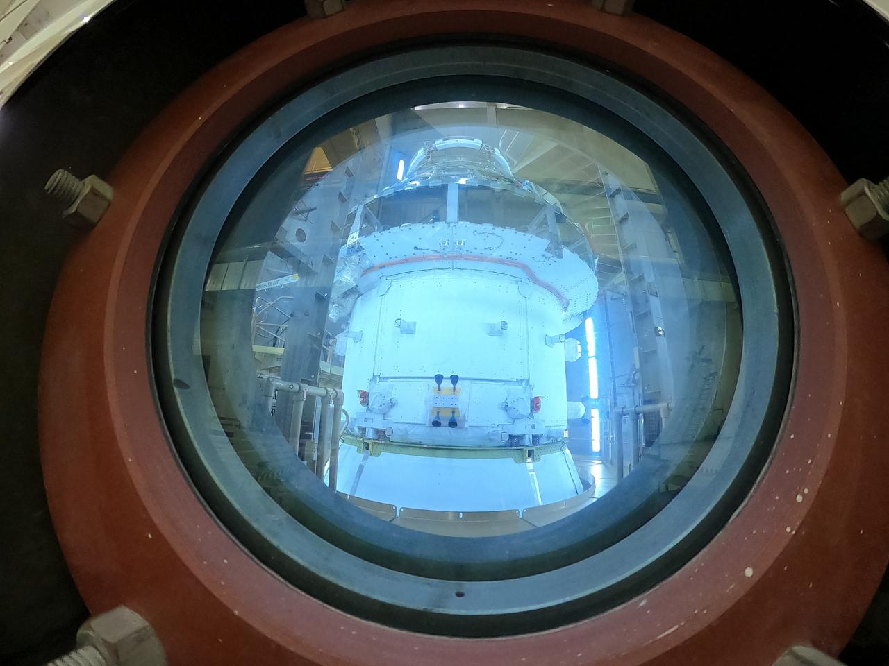
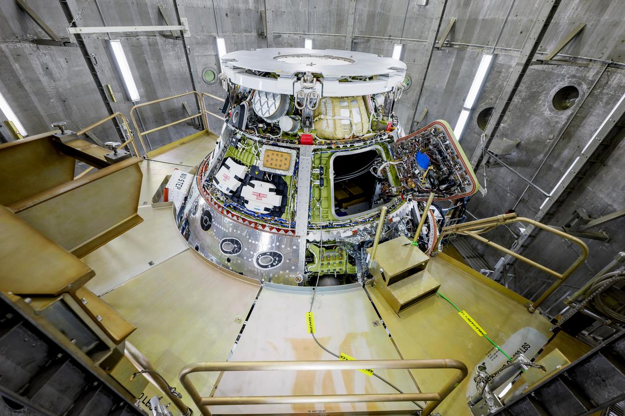
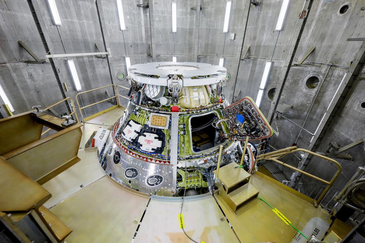
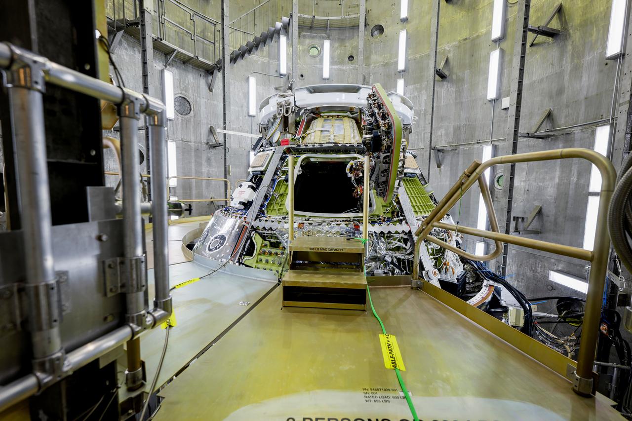
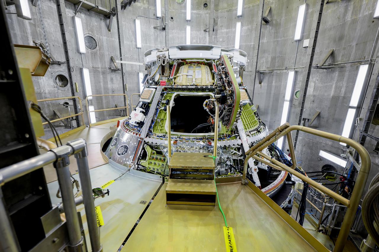
Technicians capture a photo of NASA’s Orion spacecraft inside the altitude chamber to complete further testing on Friday, Nov. 8, 2024, inside the Neil A. Armstrong Operations and Checkout building at NASA's Kennedy Space Center in Florida. The altitude chamber simulates deep space vacuum conditions, and the testing will provide additional data to augment data gained during testing earlier this summer. The Orion spacecraft will carry NASA astronauts Victor Glover, Christina Koch, and Reid Wiseman, as well as CSA (Canadian Space Agency) astronaut Jeremy Hansen, on a 10-day journey around the Moon and back for the Artemis II test flight.
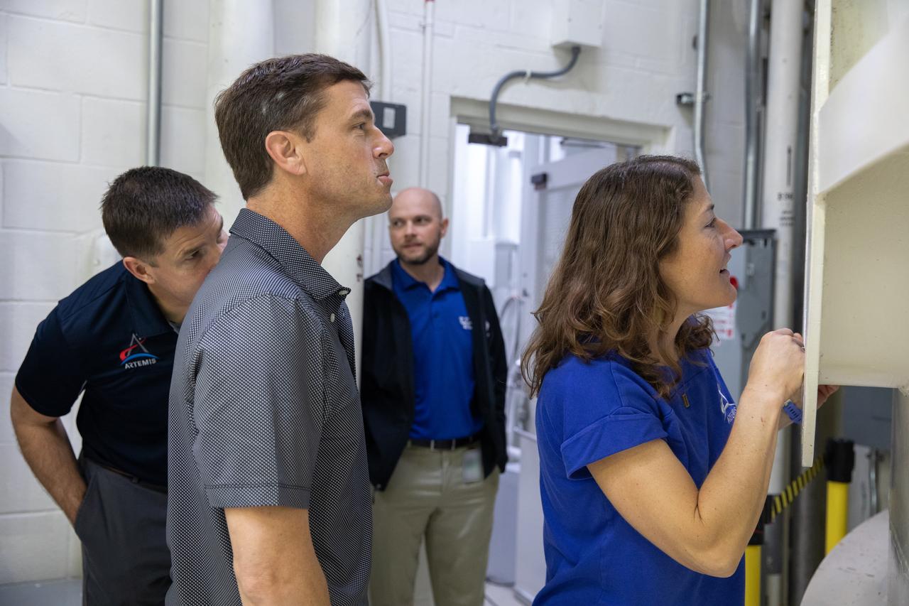
From left, Canadian Space Agency (CSA) astronaut Jeremy Hansen, along with NASA astronauts Reid Wiseman and Christina Koch view NASA’s Orion spacecraft as it undergoes testing inside the altitude chamber on Tuesday, Nov. 19, 2024, inside the Neil A. Armstrong Operations and Checkout building at NASA's Kennedy Space Center in Florida. The altitude chamber simulates deep space vacuum conditions, and the testing will provide additional data to augment data gained during testing earlier this summer. The Orion spacecraft will carry NASA astronauts Victor Glover, Koch, and Wiseman, as well as Hansen, on a 10-day journey around the Moon and back for the Artemis II test flight.

A technician connects support straps to a crane as it prepares to lift NASA’s Orion spacecraft out of the Final Assembly and Systems Testing cell to the altitude chamber inside the Neil A. Armstrong Operations and Checkout building at NASA’s Kennedy Space Center in Florida on Thursday, Nov. 7, 2024. The altitude chamber simulates deep space vacuum conditions, and the testing will provide additional data to augment data gained during testing earlier this summer. The Orion spacecraft will carry NASA astronauts Victor Glover, Christina Koch, and Reid Wiseman, as well as CSA (Canadian Space Agency) astronaut Jeremy Hansen, on a 10-day journey around the Moon and back for the Artemis II test flight.

Teams with NASA and Lockheed Martin prepare to conduct testing on NASA’s Orion spacecraft on Thursday, Nov. 7, 2024, in the altitude chamber inside the Neil A. Armstrong Operations and Checkout building at NASA’s Kennedy Space Center in Florida. The altitude chamber simulates deep space vacuum conditions, and the testing will provide additional data to augment data gained during testing earlier this summer. The Orion spacecraft will carry NASA astronauts Victor Glover, Christina Koch, and Reid Wiseman, as well as CSA (Canadian Space Agency) astronaut Jeremy Hansen, on a 10-day journey around the Moon and back for the Artemis II test flight.
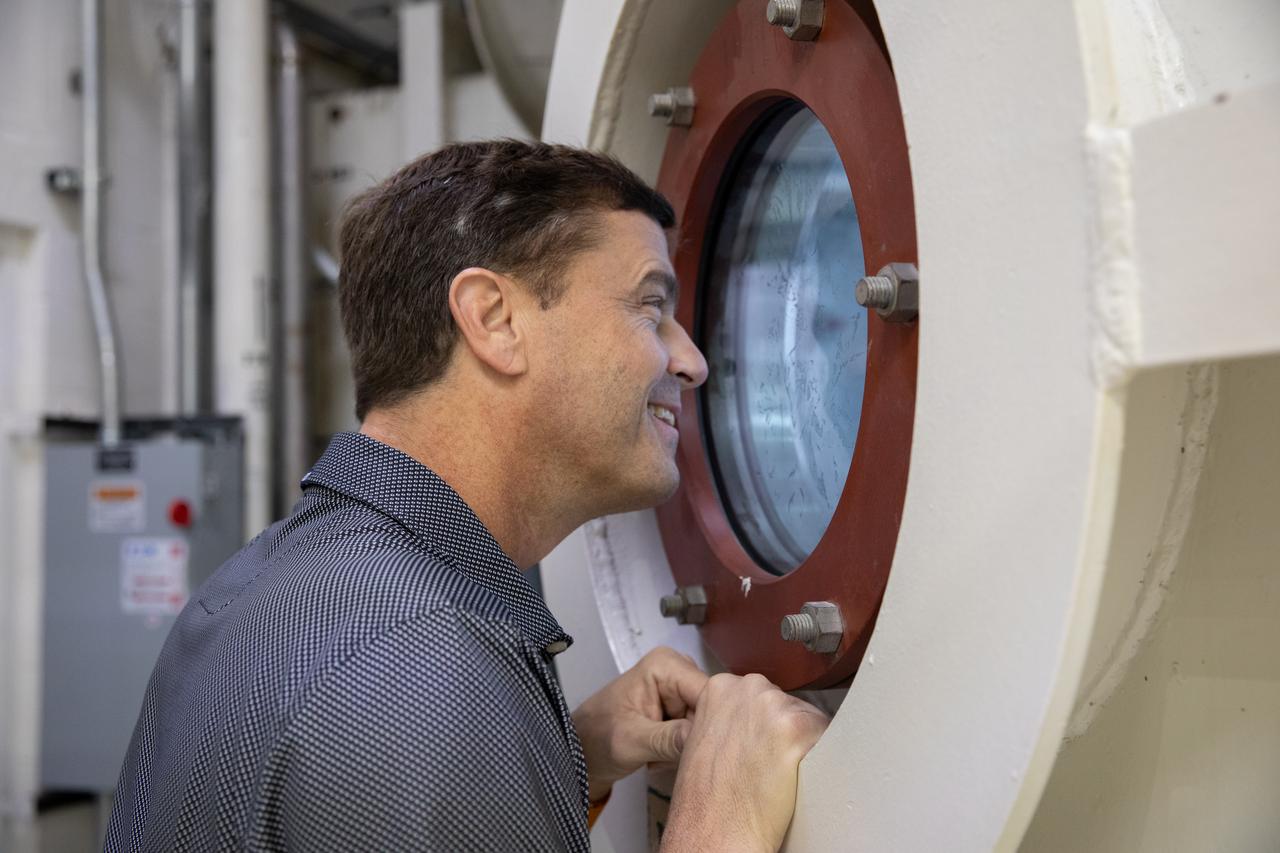
NASA astronaut Reid Wiseman views NASA’s Orion spacecraft as it undergoes testing inside the altitude chamber on Tuesday, Nov. 19, 2024, inside the Neil A. Armstrong Operations and Checkout building at NASA's Kennedy Space Center in Florida. The altitude chamber simulates deep space vacuum conditions, and the testing will provide additional data to augment data gained during testing earlier this summer. The Orion spacecraft will carry NASA astronauts Victor Glover, Christina Koch, and Wiseman, as well as CSA (Canadian Space Agency) astronaut Jeremy Hansen, on a 10-day journey around the Moon and back for the Artemis II test flight.
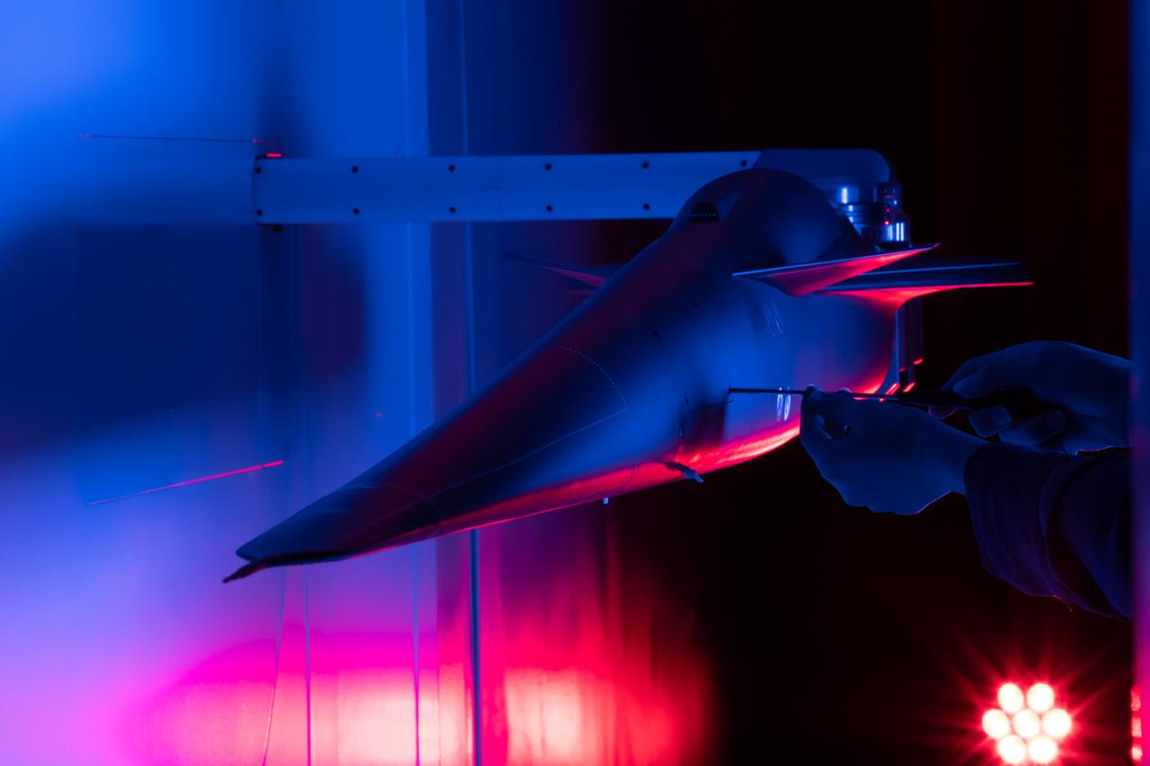
Event: Forebody and Nose - Windtunnel Testing A technician works on the X-59 model during testing in the low-speed wind tunnel at Lockheed Martin Skunk Works in Palmdale, California. These tests gave the team measurements of wind flow angle around the aircraft’s nose and confirmed computer predictions made using computational fluid dynamics (CFD) software tools. The data will be fed into the aircraft flight control system to tell the pilot the aircraft’s altitude, speed, and angle. This is part of NASA’s Quesst mission which plans to help enable supersonic air travel over land.
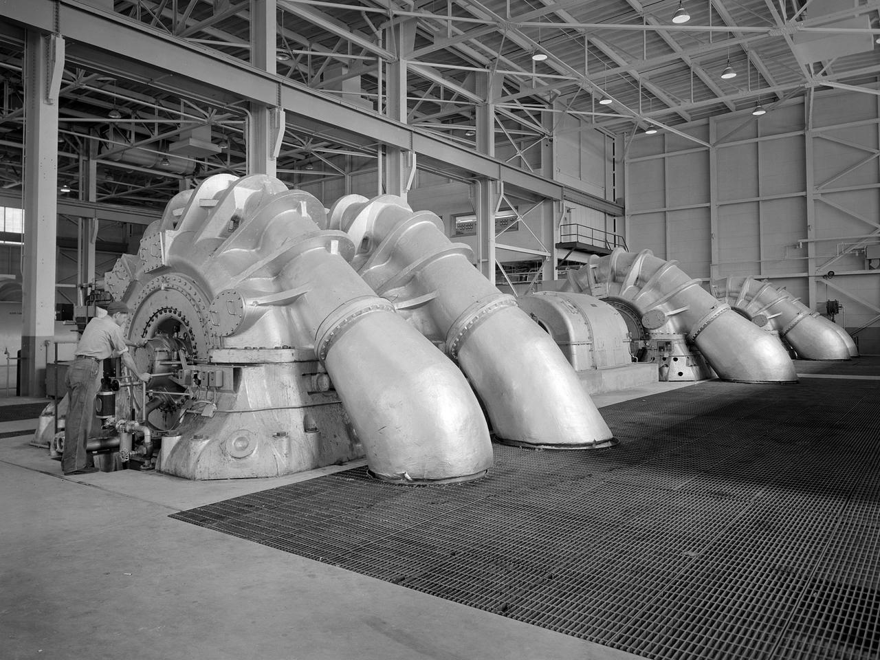
The Propulsion Systems Laboratory’s exhaust system was expanded in 1955 at the National Advisory Committee for Aeronautics (NACA) Lewis Flight Propulsion Laboratory. The facility contained two altitude chambers that were first used to study the increasingly-powerful jet engines of the early 1950s and the ramjets for missile programs such as Navaho and Bomarc. Later, the facility tested large rocket engines and a variety of turbofan engines. The exhaust system served two roles: reducing the density of the air in the test chambers to simulate high altitudes and removing the hot gases exhausted by the engines being tested. These tasks were accomplished by large Roots-Connersville exhauster equipment in the Equipment Building. The original configuration could exhaust the 3500° F gases at a rate of 100 pounds per second when the simulated altitude was 50,000 feet. In 1955, three years after operation started, a fourth line of exhausters was added. There were three centrifugal exhausters capable of supplying 166 pounds of air per second at the test chamber altitude of 50,000 feet or 384 pounds per second at 32,000 feet. These exhausters had two first-stage castings driven by a 10,000-horsepower motor; one second; one third; and one fourth-stage casting driven by a 16,500-horsepower motor. The total inlet volume of the exhausters is 1,650,000 cubic feet of gas per minute. The exhausters were continually improved and upgraded over the years.
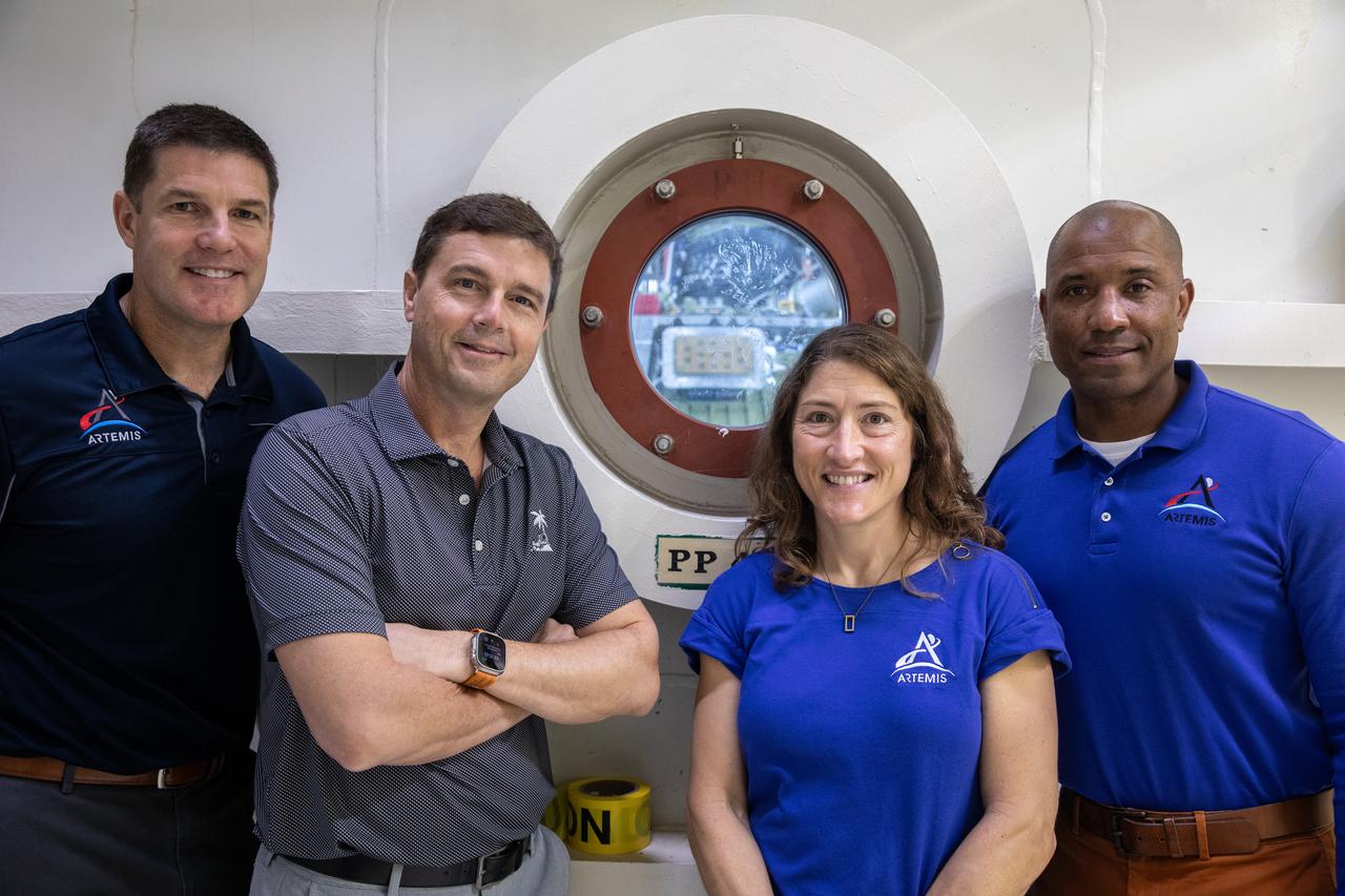
From left, the Artemis II crew, Canadian Space Agency (CSA) astronaut Jeremy Hansen, along with NASA astronauts Reid Wiseman, Christina Koch, and Victor Glover pose for a photograph in front of the altitude chamber on Tuesday, Nov. 19, 2024, inside the Neil A. Armstrong Operations and Checkout building at NASA's Kennedy Space Center in Florida. The altitude chamber simulates deep space vacuum conditions, and the testing will provide additional data to augment data gained during testing earlier this summer. The Orion spacecraft will carry the crew on a 10-day journey around the Moon and back for the Artemis II test flight.
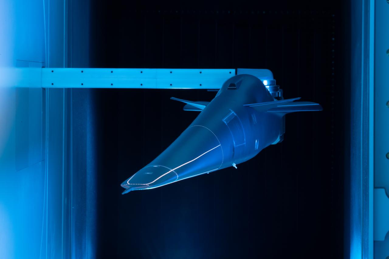
Event: Forebody and Nose - Windtunnel Testing A model of the X-59 forebody is shown in the Lockheed Martin Skunk Works’ wind tunnel in Palmdale, California. These tests gave the team measurements of wind flow angle around the aircraft’s nose and confirmed computer predictions made using computational fluid dynamics (CFD) software tools. The data will be fed into the aircraft flight control system to tell the pilot the aircraft’s altitude, speed and angle. This is part of NASA’s Quesst mission which plans to help enable supersonic air travel over land.
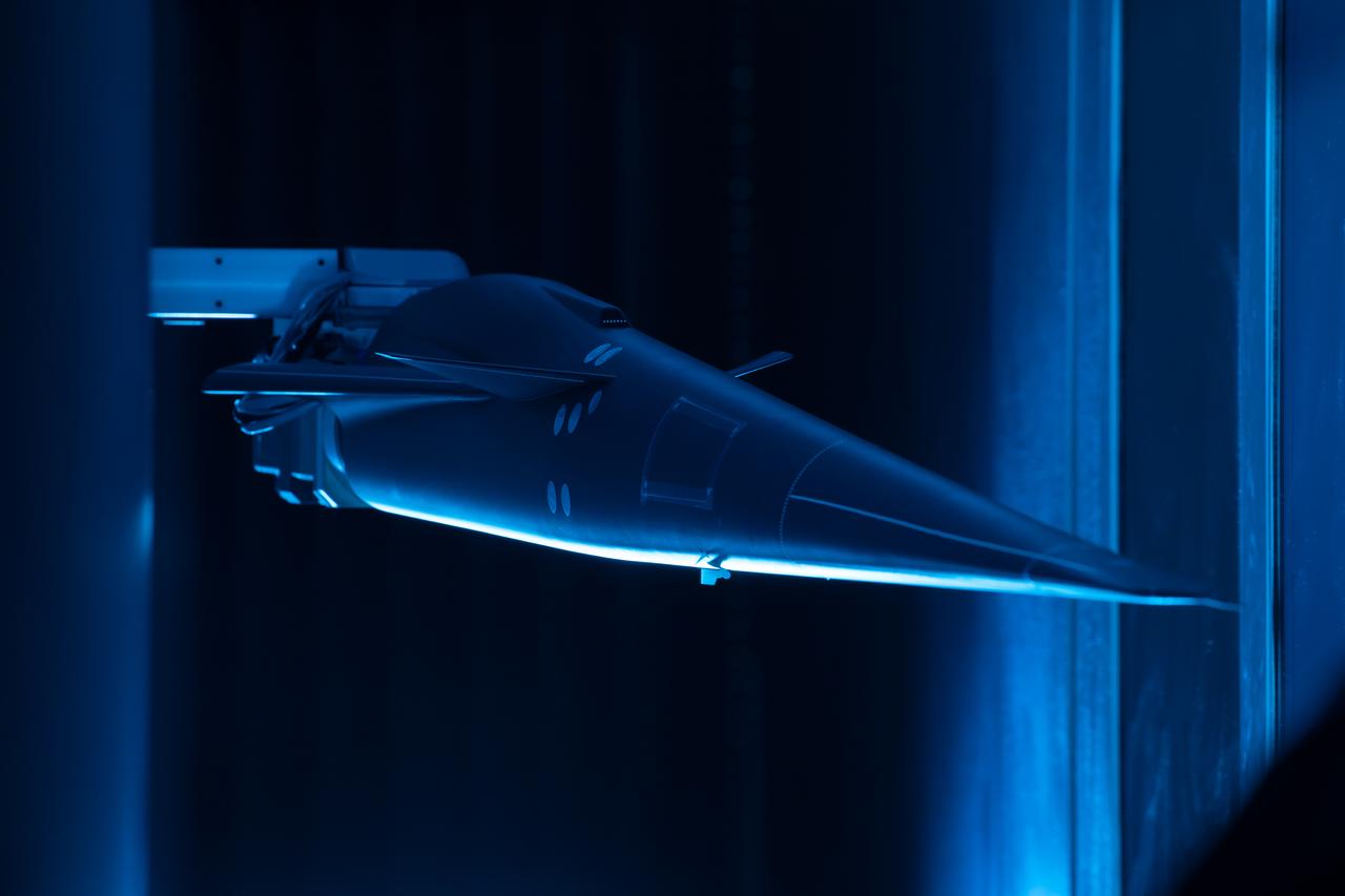
Event: Forebody and Nose - Windtunnel Testing A model of the X-59 forebody is shown in the Lockheed Martin Skunk Works’ wind tunnel in Palmdale, California. These tests gave the team measurements of wind flow angle around the aircraft’s nose and confirmed computer predictions made using computational fluid dynamics (CFD) software tools. The data will be fed into the aircraft flight control system to tell the pilot the aircraft’s altitude, speed and angle. This is part of NASA’s Quesst mission which plans to help enable supersonic air travel over land.
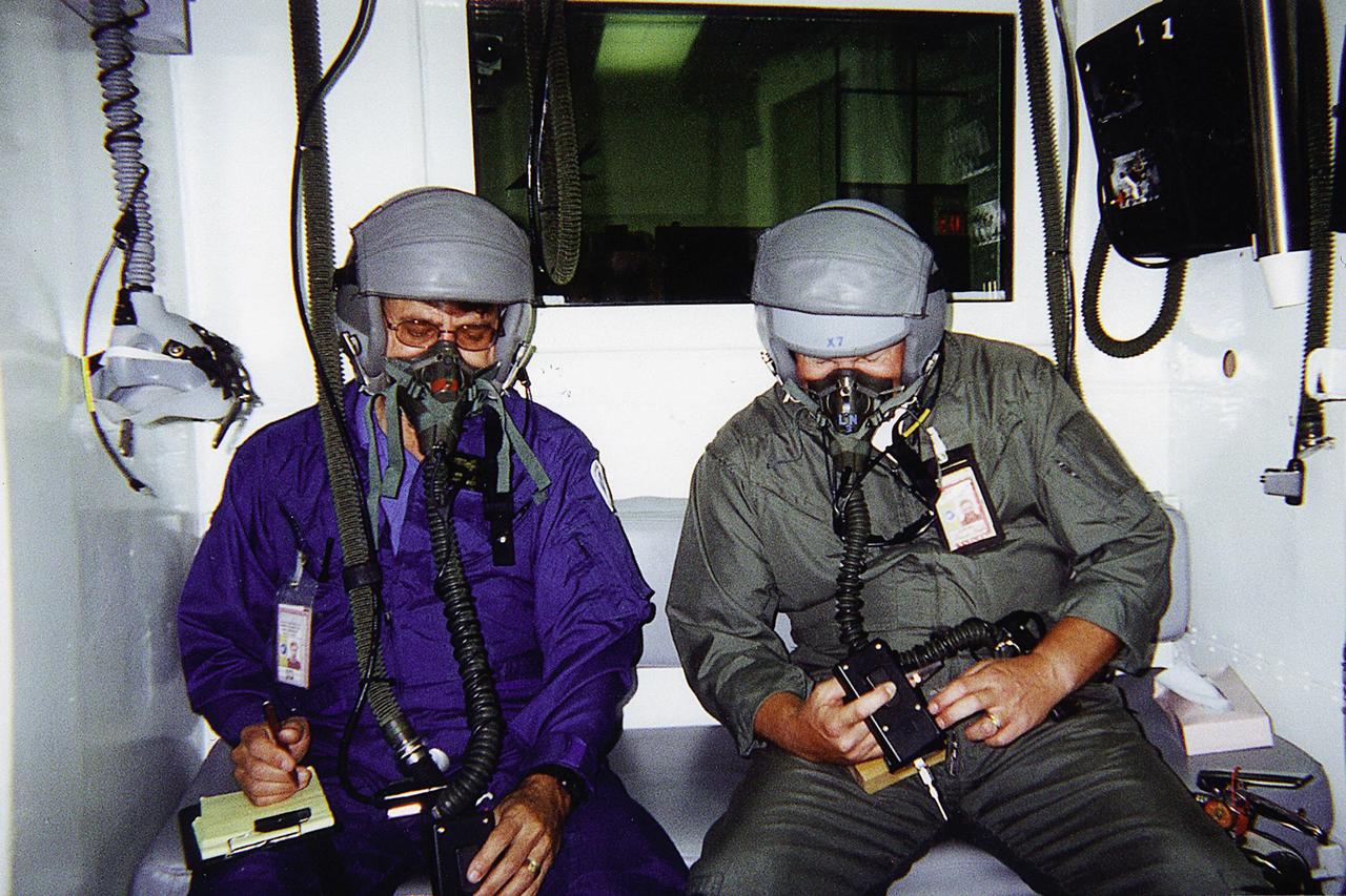
Jan Zysko (left) and Rich Mizell (right) test a Personal Cabin Pressure Altitude Monitor in an altitude chamber at Tyndall Air Force Base in Florida. Zysko invented the pager-sized monitor that alerts wearers of a potentially dangerous or deteriorating cabin pressure altitude condition, which can lead to life-threatening hypoxia. Zysko is chief of the KSC Spaceport Engineering and Technology directorate's data and electronic systems branch. Mizell is a Shuttle processing engineer. The monitor, which has drawn the interest of such organizations as the Federal Aviation Administration for use in commercial airliners and private aircraft, was originally designed to offer Space Shuttle and Space Station crew members added independent notification about any depressurization

Jan Zysko (left) and Rich Mizell (right) test a Personal Cabin Pressure Altitude Monitor in an altitude chamber at Tyndall Air Force Base in Florida. Zysko invented the pager-sized monitor that alerts wearers of a potentially dangerous or deteriorating cabin pressure altitude condition, which can lead to life-threatening hypoxia. Zysko is chief of the KSC Spaceport Engineering and Technology directorate's data and electronic systems branch. Mizell is a Shuttle processing engineer. The monitor, which has drawn the interest of such organizations as the Federal Aviation Administration for use in commercial airliners and private aircraft, was originally designed to offer Space Shuttle and Space Station crew members added independent notification about any depressurization
On April 10, 2024, the Artemis II Orion spacecraft is seen inside the west altitude chamber in the Operations and Checkout Building at NASA's Kennedy Space Center in Florida, where it will undergo electromagnetic interference and compatibility testing.
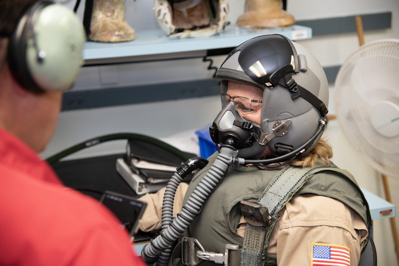
NASA Armstrong videographer Lori Losey undergoes pressure breathing training in San Antonio, Texas. NASA Armstrong aircrews are preparing for high altitude flight tests of the X-59.
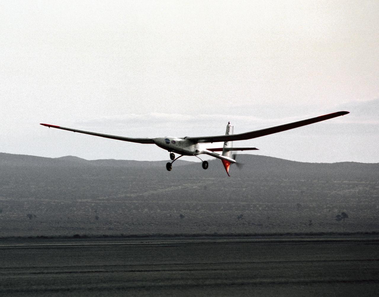
The Perseus proof-of-concept vehicle flies over Rogers Dry Lake at the Dryden Flight Research Center, Edwards, California, to test basic design concepts for the remotely-piloted, high-altitude vehicle.
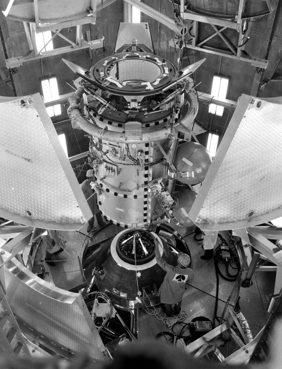
KENNEDY SPACE CENTER, FLA. -- NASA_APOLLO-SOYUZ: Fit checks were performed in an altitude chamber at KSC today between the Apollo spacecraft and the Docking Module to be used during the Apollo Soyuz Test Project.
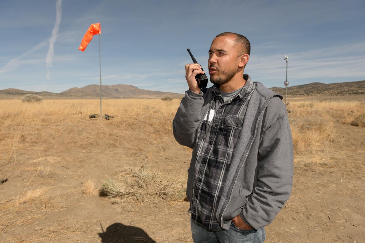
Test of Unmanned Aircraft Systems Traffic Management (UTM) technical capability Level 2 (TCL2) at Reno-Stead Airport, Nevada. During the test, five drones simultaneously crossed paths, separated by altitude. Two drones flew beyond visual line-of-sight and three flew within line-of-sight of their operators.
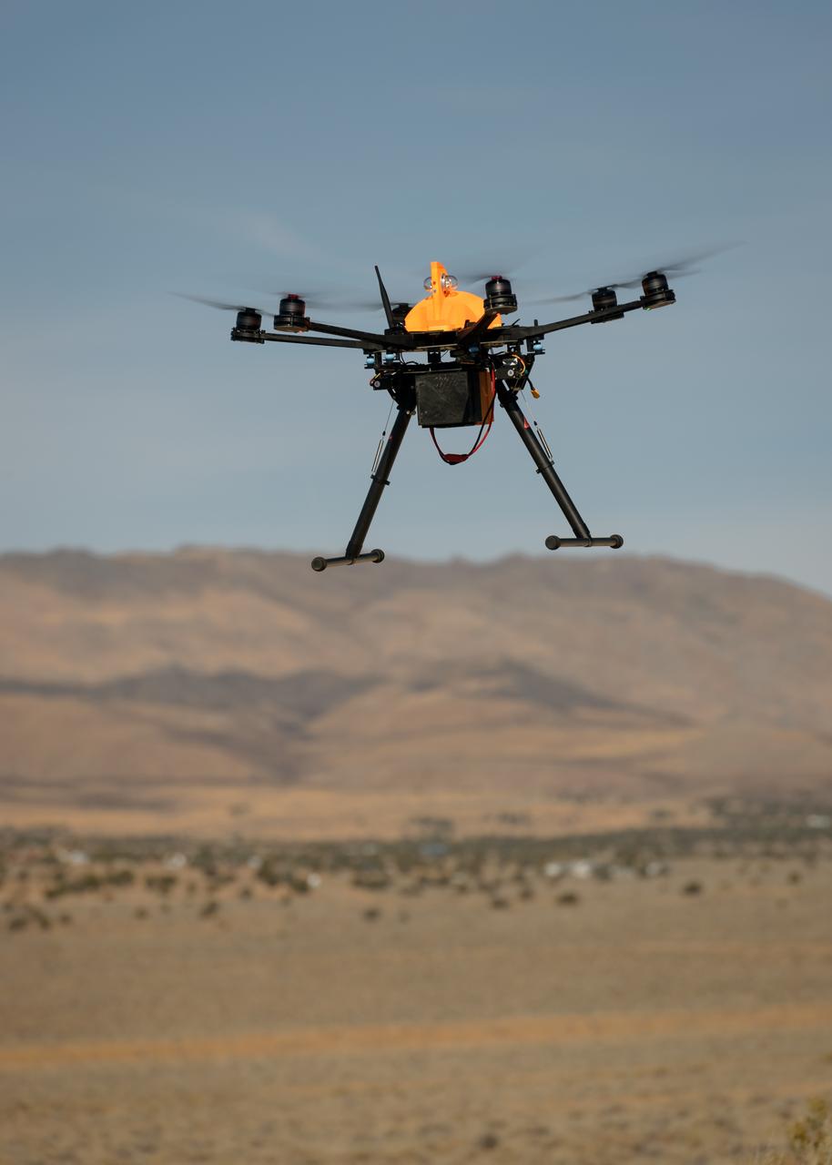
Test of Unmanned Aircraft Systems Traffic Management (UTM) technical capability Level 2 (TCL2) at Reno-Stead Airport, Nevada. During the test, five drones simultaneously crossed paths, separated by altitude. Two drones flew beyond visual line-of-sight and three flew within line-of-sight of their operators.
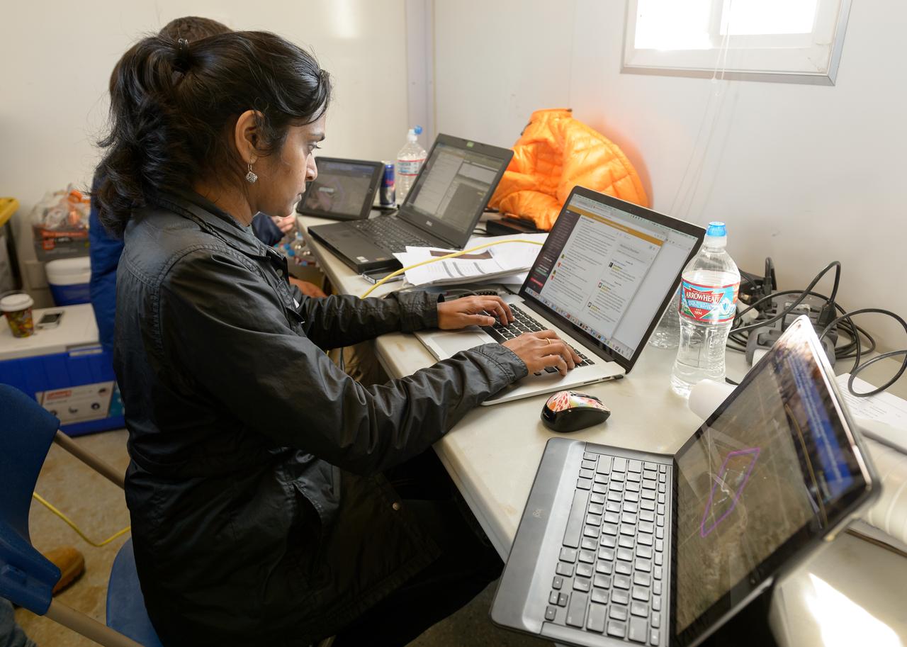
Test of Unmanned Aircraft Systems Traffic Management (UTM) technical capability Level 2 (TCL2) at Reno-Stead Airport, Nevada. During the test, five drones simultaneously crossed paths, separated by altitude. Two drones flew beyond visual line-of-sight and three flew within line-of-sight of their operators.