NASA’s X-59 quiet supersonic research aircraft successfully completed its “aluminum bird” systems test at Lockheed Martin’s Skunk Works facility in Palmdale, California. With NASA pilot James Less in the cockpit, the X-59 team simulated flight conditions from takeoff to landing – without ever leaving the ground. The test verified how the aircraft’s hardware and software work together, responding to pilot inputs and handling injected system failures. This milestone confirms the aircraft’s readiness for the next series of tests leading to first flight.
NASA’s X-59 Completes 'Aluminum Bird' Test
iss066e078282 (November 17, 2021) --- NASA astronaut Tom Marshburn works on the SUBSA-BRAINS space physics experiment, which examines differences in capillary flow, interface reactions, and bubble formation during solidification of brazing alloys in microgravity. Brazing technology bonds similar materials (such as an aluminum alloy to aluminum) or dissimilar ones (such as aluminum alloy to ceramics) at temperatures above 450°C. It is a potential tool for construction of human space habitats and manufactured systems as well as to repair damage from micrometeoroids or space debris.
SUBSA-BRAINS (BRazing of Aluminum alloys IN Space) space physics experiment
STS-42 closeup view shows Student Experiment 81-09 (SE 81-09), Convection in Zero Gravity experiment, with radial pattern caused by convection induced by heating an oil and aluminum powder mixture in the weightlessness of space. While the STS-42 crewmembers activated the Shuttle Student Involvement Program (SSIP) experiment on Discovery's, Orbiter Vehicle (OV) 103's, middeck, Scott Thomas, the student who designed the experiment, was able to observe the procedures via downlinked television (TV) in JSC's Mission Control Center (MCC). Thomas, now a physics doctoral student at the University of Texas, came up with the experiment while he participated in the SSIP as a student at Richland High School in Johnstown, Pennsylvia.
STS-42 closeup view shows SE 81-09 Convection in Zero Gravity experiment
The structure of NASA Mars Reconnaissance Orbiter spacecraft is constructed from composite panels of carbon layers over aluminum honeycomb, lightweight yet strong.
Orbiter Skeleton
The piece of metal with the American flag on it in this image of a NASA rover on Mars is made of aluminum recovered from the site of the World Trade Center towers in the weeks after their destruction.
Interplanetary Memorial to Victims of Sept. 11, 2001
The aluminum telescope of NASA’s Near-Earth Object (NEO) Surveyor mission is shown here attached its flight base frame at a Space Dynamics Laboratory (SDL) clean room in Logan, Utah, in early September 2025. The telescope is connected via a system of struts that prevent heat from passing from the spacecraft to the instrument, keeping it secure, isolated, and cool. The spacecraft’s instrument enclosure will later be fitted over the instrumentation and then the pair will be attached to the spacecraft bus and sunshade.  With an aperture of nearly 20 inches (50 centimeters), the telescope features detectors sensitive to two infrared wavelengths in which near-Earth objects re-radiate solar heat. The instrument enclosure is designed to ensure heat produced by the spacecraft and instrument during operations doesn’t interfere with its infrared observations.  Targeting launch in late 2027, the NEO Surveyor mission is led by Professor Amy Mainzer at the University of California, Los Angeles for NASA’s Planetary Defense Coordination Office and is being managed by the agency’s Jet Propulsion Laboratory in Southern California for the Planetary Missions Program Office at NASA’s Marshall Space Flight Center in Huntsville, Alabama. BAE Systems and the Space Dynamics Laboratory in Logan, Utah, and Teledyne are among the companies that were contracted to build the spacecraft and its instrumentation. The Laboratory for Atmospheric and Space Physics at the University of Colorado Boulder will support operations, and IPAC at Caltech in Pasadena, California, is responsible for producing some of the mission’s data products. Caltech manages JPL for NASA.  More information about NEO Surveyor is available at:  https://science.nasa.gov/mission/neo-surveyor/
NEO Surveyor’s Aluminum Telescope Mounted to Its Flight Base
This image from NASA shows a particle impact on the aluminum frame that holds the aerogel tiles. The debris from the impact shot into the adjacent aerogel tile producing the explosion pattern of ejecta framents captured in the material.
Comet Ejecta in Aerogel
A Martian target rock called Nova, shown here, displayed an increasing concentration of aluminum as a series of laser shots from NASA Curiosity Mars rover penetrated through dust on the rock surface.
Curiosity ChemCam Examines Mars Rock Target Nova
An etched sample of the aluminum indium alloy (magnified). When the hypermonotectic mixture is cooled in the Advanced Gradient Hearing Facility (AGHF), aluminum transitions to a solid first, trapping the indium in cylindrical fibers within the solid. Principal Investigator: Dr. Barry Andrews
Microgravity
Members of NASA's Mars 2020 Perseverance rover mission installed a plate on the left side of the rover chassis, commemorating the impact of the COVID-19 pandemic and paying tribute to the perseverance of healthcare workers around the world. Made of aluminum, the 3-by-5-inch (8-by-13-centimeter) plaque was attached to the rover in May 2020 during final assembly at Kennedy Space Center in Florida.  https://photojournal.jpl.nasa.gov/catalog/PIA23921
Healthcare Workers to Be Honored on Mars
More than 1,500 individual pieces of carbon fiber, flight-grade aluminum, silicon, copper, foil and foam go into a Mars Helicopter. This image of the Flight Model (the actual vehicle going to the Red Planet), was taken on Feb. 1, 2019 when the helicopter was inside the Space Simulator, a 25-foot (7.62 meter) wide vacuum chamber at NASA's Jet Propulsion Laboratory in Pasadena, California.  https://photojournal.jpl.nasa.gov/catalog/PIA23158
This Helicopter is Going to Mars
This image from NASA Terra spacecraft shows the world largest bauxite mine found near Weipa, Queensland, Australia. The rich aluminum deposits were first recognized on the end of the Cape York Peninsula in 1955, and mining began in 1960.
Weipa, Queensland, Australia
NASA structural materials engineer, Jonathan Lee, displays blocks and pistons as examples of some of the uses for NASA’s patented high-strength aluminum alloy originally developed at Marshall Space Flight Center in Huntsville, Alabama. NASA desired an alloy for aerospace applications with higher strength and wear-resistance at elevated temperatures.  The alloy is a solution to reduce costs of aluminum engine pistons and lower engine emissions for the automobile industry. The Boats and Outboard Engines Division at Bombardier Recreational Products of Sturtevant, Wisconsin is using the alloy for pistons in its Evinrude E-Tec outboard engine line.
Benefit from NASA
A 3 mm-diameter droplet of aluminum oxide, heated to 2371 deg. C (4,300 deg. F), is suspended in midair by six acoustic transducers. A gas jet (from the nozzle below the drop) helps position the drop for study, and a 500-watt laser melts the sample. Glasses made from aluminum oxide are highly promising for optical transmission and other properties. They are also highly reactive when molten. Containerless processing allows studies of how to form amorphous (glassy) rather than crystalline metal oxides. Credit: Bill Jellison, Containerless Research, Inc.
Microgravity
KENNEDY SPACE CENTER, FLA. -  William Gaetjens (background), with the Vehicle Integration Test Team (VITT) directs Japanese astronaut Koichi Wakata’s attention to the spars installed on the wing of the orbiter Atlantis.  Reinforced Carbon Carbon (RCC) panels are mechanically attached to the wing via the spars - a series of floating joints - to reduce loading on the panels caused by wing deflections. The aluminum and the metallic attachments are protected from exceeding temperature limits by internal insulation.
KENNEDY SPACE CENTER, FLA. - William Gaetjens (background), with the Vehicle Integration Test Team (VITT) directs Japanese astronaut Koichi Wakata’s attention to the spars installed on the wing of the orbiter Atlantis. Reinforced Carbon Carbon (RCC) panels are mechanically attached to the wing via the spars - a series of floating joints - to reduce loading on the panels caused by wing deflections. The aluminum and the metallic attachments are protected from exceeding temperature limits by internal insulation.
KENNEDY SPACE CENTER, FLA. -  In the Orbiter Processing Facility, Mike Hyatt, with United Space Alliance, installs a spar on the wing of the orbiter Atlantis.  Reinforced Carbon Carbon (RCC) panels are mechanically attached to the wing with a series of floating joints - spars - to reduce loading on the panels caused by wing deflections. The aluminum and the metallic attachments are protected from exceeding temperature limits by internal insulation.
KENNEDY SPACE CENTER, FLA. - In the Orbiter Processing Facility, Mike Hyatt, with United Space Alliance, installs a spar on the wing of the orbiter Atlantis. Reinforced Carbon Carbon (RCC) panels are mechanically attached to the wing with a series of floating joints - spars - to reduce loading on the panels caused by wing deflections. The aluminum and the metallic attachments are protected from exceeding temperature limits by internal insulation.
KENNEDY SPACE CENTER, FLA. - In the Orbiter Processing Facility, John Newport, with United Space Alliance, inspects a spar to be installed on the wing of the orbiter Atlantis.  Reinforced Carbon Carbon (RCC) panels are mechanically attached to the wing with a series of floating joints - spars - to reduce loading on the panels caused by wing deflections. The aluminum and the metallic attachments are protected from exceeding temperature limits by internal insulation.
KENNEDY SPACE CENTER, FLA. - In the Orbiter Processing Facility, John Newport, with United Space Alliance, inspects a spar to be installed on the wing of the orbiter Atlantis. Reinforced Carbon Carbon (RCC) panels are mechanically attached to the wing with a series of floating joints - spars - to reduce loading on the panels caused by wing deflections. The aluminum and the metallic attachments are protected from exceeding temperature limits by internal insulation.
KENNEDY SPACE CENTER, FLA. - Japanese astronaut Koichi Wakata gestures as he examines the spar installation (behind him) on the wing of the orbiter Atlantis.  Reinforced Carbon Carbon (RCC) panels are mechanically attached to the wing via the spars - a series of floating joints - to reduce loading on the panels caused by wing deflections. The aluminum and the metallic attachments are protected from exceeding temperature limits by internal insulation.
KENNEDY SPACE CENTER, FLA. - Japanese astronaut Koichi Wakata gestures as he examines the spar installation (behind him) on the wing of the orbiter Atlantis. Reinforced Carbon Carbon (RCC) panels are mechanically attached to the wing via the spars - a series of floating joints - to reduce loading on the panels caused by wing deflections. The aluminum and the metallic attachments are protected from exceeding temperature limits by internal insulation.
KENNEDY SPACE CENTER, FLA. - In the Orbiter Processing Facility, John Newport, with United Space Alliance, inspects spar installation on the wing of the orbiter Atlantis.  Reinforced Carbon Carbon (RCC) panels are mechanically attached to the wing with a series of floating joints - spars - to reduce loading on the panels caused by wing deflections. The aluminum and the metallic attachments are protected from exceeding temperature limits by internal insulation.
KENNEDY SPACE CENTER, FLA. - In the Orbiter Processing Facility, John Newport, with United Space Alliance, inspects spar installation on the wing of the orbiter Atlantis. Reinforced Carbon Carbon (RCC) panels are mechanically attached to the wing with a series of floating joints - spars - to reduce loading on the panels caused by wing deflections. The aluminum and the metallic attachments are protected from exceeding temperature limits by internal insulation.
KENNEDY SPACE CENTER, FLA. - In the Orbiter Processing Facility, Mike Hyatt (left) and Saul Ngy (right), with United Space Alliance, finish installing a spar on the wing of the orbiter Atlantis.  Reinforced Carbon Carbon (RCC) panels are mechanically attached to the wing with a series of floating joints - spars - to reduce loading on the panels caused by wing deflections. The aluminum and the metallic attachments are protected from exceeding temperature limits by internal insulation.
KENNEDY SPACE CENTER, FLA. - In the Orbiter Processing Facility, Mike Hyatt (left) and Saul Ngy (right), with United Space Alliance, finish installing a spar on the wing of the orbiter Atlantis. Reinforced Carbon Carbon (RCC) panels are mechanically attached to the wing with a series of floating joints - spars - to reduce loading on the panels caused by wing deflections. The aluminum and the metallic attachments are protected from exceeding temperature limits by internal insulation.
KENNEDY SPACE CENTER, FLA. - In the Orbiter Processing Facility (OPF), a United Space Alliance technician examines the attachment points for the spars on the exterior of a wing of Space Shuttle Atlantis. Reinforced Carbon Carbon (RCC) panels are mechanically attached to the wing with a series of floating joints - spars - to reduce loading on the panels caused by wing deflections. The aluminum and the metallic attachments are protected from exceeding temperature limits by internal insulation.  The next launch of Atlantis will be on mission STS-114, a utilization and logistics flight to the International Space Station.
KENNEDY SPACE CENTER, FLA. - In the Orbiter Processing Facility (OPF), a United Space Alliance technician examines the attachment points for the spars on the exterior of a wing of Space Shuttle Atlantis. Reinforced Carbon Carbon (RCC) panels are mechanically attached to the wing with a series of floating joints - spars - to reduce loading on the panels caused by wing deflections. The aluminum and the metallic attachments are protected from exceeding temperature limits by internal insulation. The next launch of Atlantis will be on mission STS-114, a utilization and logistics flight to the International Space Station.
KENNEDY SPACE CENTER, FLA. - In the Orbiter Processing Facility, John Newport, with United Space Alliance, inspects a piece of equipment for spar installation on the wing of the orbiter Atlantis.  Reinforced Carbon Carbon (RCC) panels are mechanically attached to the wing with a series of floating joints - spars - to reduce loading on the panels caused by wing deflections. The aluminum and the metallic attachments are protected from exceeding temperature limits by internal insulation.
KENNEDY SPACE CENTER, FLA. - In the Orbiter Processing Facility, John Newport, with United Space Alliance, inspects a piece of equipment for spar installation on the wing of the orbiter Atlantis. Reinforced Carbon Carbon (RCC) panels are mechanically attached to the wing with a series of floating joints - spars - to reduce loading on the panels caused by wing deflections. The aluminum and the metallic attachments are protected from exceeding temperature limits by internal insulation.
KENNEDY SPACE CENTER, FLA. - In the Orbiter Processing Facility (OPF), a United Space Alliance technician examines the attachment points for the spars on the exterior of a wing of Space Shuttle Atlantis. Reinforced Carbon Carbon (RCC) panels are mechanically attached to the wing with a series of floating joints - spars - to reduce loading on the panels caused by wing deflections. The aluminum and the metallic attachments are protected from exceeding temperature limits by internal insulation.  The next launch of Atlantis will be on mission STS-114, a utilization and logistics flight to the International Space Station.
KENNEDY SPACE CENTER, FLA. - In the Orbiter Processing Facility (OPF), a United Space Alliance technician examines the attachment points for the spars on the exterior of a wing of Space Shuttle Atlantis. Reinforced Carbon Carbon (RCC) panels are mechanically attached to the wing with a series of floating joints - spars - to reduce loading on the panels caused by wing deflections. The aluminum and the metallic attachments are protected from exceeding temperature limits by internal insulation. The next launch of Atlantis will be on mission STS-114, a utilization and logistics flight to the International Space Station.
KENNEDY SPACE CENTER, FLA. -  Mike Hyatt (left) and Saul Ngy, technicians with United Space Alliance, install a spar on the wing of the orbiter Atlantis.  The Reinforced Carbon Carbon (RCC) panels are mechanically attached to the wing with a series of floating joints - spars - to reduce loading on the panels caused by wing deflections. The aluminum and the metallic attachments are protected from exceeding temperature limits by internal insulation.
KENNEDY SPACE CENTER, FLA. - Mike Hyatt (left) and Saul Ngy, technicians with United Space Alliance, install a spar on the wing of the orbiter Atlantis. The Reinforced Carbon Carbon (RCC) panels are mechanically attached to the wing with a series of floating joints - spars - to reduce loading on the panels caused by wing deflections. The aluminum and the metallic attachments are protected from exceeding temperature limits by internal insulation.
KENNEDY SPACE CENTER, FLA. - In the Orbiter Processing Facility, Mike Hyatt (above) and Saul Ngy (below), with United Space Alliance, install a spar on the wing of the orbiter Atlantis.  Reinforced Carbon Carbon (RCC) panels are mechanically attached to the wing with a series of floating joints - spars - to reduce loading on the panels caused by wing deflections. The aluminum and the metallic attachments are protected from exceeding temperature limits by internal insulation.
KENNEDY SPACE CENTER, FLA. - In the Orbiter Processing Facility, Mike Hyatt (above) and Saul Ngy (below), with United Space Alliance, install a spar on the wing of the orbiter Atlantis. Reinforced Carbon Carbon (RCC) panels are mechanically attached to the wing with a series of floating joints - spars - to reduce loading on the panels caused by wing deflections. The aluminum and the metallic attachments are protected from exceeding temperature limits by internal insulation.
KENNEDY SPACE CENTER, FLA. - Japanese astronaut Koichi Wakata looks at the spars installed on the wing of the orbiter Atlantis.  Reinforced Carbon Carbon (RCC) panels are mechanically attached to the wing via the spars - a series of floating joints - to reduce loading on the panels caused by wing deflections. The aluminum and the metallic attachments are protected from exceeding temperature limits by internal insulation.
KENNEDY SPACE CENTER, FLA. - Japanese astronaut Koichi Wakata looks at the spars installed on the wing of the orbiter Atlantis. Reinforced Carbon Carbon (RCC) panels are mechanically attached to the wing via the spars - a series of floating joints - to reduce loading on the panels caused by wing deflections. The aluminum and the metallic attachments are protected from exceeding temperature limits by internal insulation.
KENNEDY SPACE CENTER, FLA. - Technician Saul Ngy, with United Space Alliance, prepares to install a spar on the wing of the orbiter Atlantis.  The Reinforced Carbon Carbon (RCC) panels are mechanically attached to the wing with a series of floating joints - spars - to reduce loading on the panels caused by wing deflections. The aluminum and the metallic attachments are protected from exceeding temperature limits by internal insulation.
KENNEDY SPACE CENTER, FLA. - Technician Saul Ngy, with United Space Alliance, prepares to install a spar on the wing of the orbiter Atlantis. The Reinforced Carbon Carbon (RCC) panels are mechanically attached to the wing with a series of floating joints - spars - to reduce loading on the panels caused by wing deflections. The aluminum and the metallic attachments are protected from exceeding temperature limits by internal insulation.
KENNEDY SPACE CENTER, FLA. -  Mike Hyatt (left) and Saul Ngy, technicians with United Space Alliance, prepare to install a spar on the wing of the orbiter Atlantis.  The Reinforced Carbon Carbon (RCC) panels are mechanically attached to the wing with a series of floating joints - spars - to reduce loading on the panels caused by wing deflections. The aluminum and the metallic attachments are protected from exceeding temperature limits by internal insulation.
KENNEDY SPACE CENTER, FLA. - Mike Hyatt (left) and Saul Ngy, technicians with United Space Alliance, prepare to install a spar on the wing of the orbiter Atlantis. The Reinforced Carbon Carbon (RCC) panels are mechanically attached to the wing with a series of floating joints - spars - to reduce loading on the panels caused by wing deflections. The aluminum and the metallic attachments are protected from exceeding temperature limits by internal insulation.
KENNEDY SPACE CENTER, FLA. - In the Orbiter Processing Facility, John Newport, with United Space Alliance, inspects the wing of the orbiter Atlantis before installing a spar. Reinforced Carbon Carbon (RCC) panels are mechanically attached to the wing with a series of floating joints - spars - to reduce loading on the panels caused by wing deflections. The aluminum and the metallic attachments are protected from exceeding temperature limits by internal insulation.
KENNEDY SPACE CENTER, FLA. -In the Orbiter Processing Facility (OPF), a United Space Alliance technician examines the attachment points for the spars on the exterior of a wing of Space Shuttle Atlantis. Reinforced Carbon Carbon (RCC) panels are mechanically attached to the wing with a series of floating joints - spars - to reduce loading on the panels caused by wing deflections. The aluminum and the metallic attachments are protected from exceeding temperature limits by internal insulation.  The next launch of Atlantis will be on mission STS-114, a utilization and logistics flight to the International Space Station.
KENNEDY SPACE CENTER, FLA. -In the Orbiter Processing Facility (OPF), a United Space Alliance technician examines the attachment points for the spars on the exterior of a wing of Space Shuttle Atlantis. Reinforced Carbon Carbon (RCC) panels are mechanically attached to the wing with a series of floating joints - spars - to reduce loading on the panels caused by wing deflections. The aluminum and the metallic attachments are protected from exceeding temperature limits by internal insulation. The next launch of Atlantis will be on mission STS-114, a utilization and logistics flight to the International Space Station.
KENNEDY SPACE CENTER, FLA. - In the Orbiter Processing Facility (OPF), United Space Alliance technicians replace the attachment points for the spars on the interior of a wing of Space Shuttle Atlantis. Reinforced Carbon Carbon (RCC) panels are mechanically attached to the wing with a series of floating joints - spars - to reduce loading on the panels caused by wing deflections. The aluminum and the metallic attachments are protected from exceeding temperature limits by internal insulation.  The next launch of Atlantis will be on mission STS-114, a utilization and logistics flight to the International Space Station.
KENNEDY SPACE CENTER, FLA. - In the Orbiter Processing Facility (OPF), United Space Alliance technicians replace the attachment points for the spars on the interior of a wing of Space Shuttle Atlantis. Reinforced Carbon Carbon (RCC) panels are mechanically attached to the wing with a series of floating joints - spars - to reduce loading on the panels caused by wing deflections. The aluminum and the metallic attachments are protected from exceeding temperature limits by internal insulation. The next launch of Atlantis will be on mission STS-114, a utilization and logistics flight to the International Space Station.
KENNEDY SPACE CENTER, FLA. - Japanese astronaut Koichi Wakata (right) listens to William Gaetjens, with the Vehicle Integration Test Team (VITT), who is providing details about the spar installation (left) on the wing of the orbiter Atlantis.  Reinforced Carbon Carbon (RCC) panels are mechanically attached to the wing via the spars - a series of floating joints - to reduce loading on the panels caused by wing deflections. The aluminum and the metallic attachments are protected from exceeding temperature limits by internal insulation.
KENNEDY SPACE CENTER, FLA. - Japanese astronaut Koichi Wakata (right) listens to William Gaetjens, with the Vehicle Integration Test Team (VITT), who is providing details about the spar installation (left) on the wing of the orbiter Atlantis. Reinforced Carbon Carbon (RCC) panels are mechanically attached to the wing via the spars - a series of floating joints - to reduce loading on the panels caused by wing deflections. The aluminum and the metallic attachments are protected from exceeding temperature limits by internal insulation.
KENNEDY SPACE CENTER, FLA. - Japanese astronaut Koichi Wakata (front) listens to William Gaetjens, with the Vehicle Integration Test Team (VITT), who is providing details about the spar installation (left) on the wing of the orbiter Atlantis.  Reinforced Carbon Carbon (RCC) panels are mechanically attached to the wing via the spars - a series of floating joints - to reduce loading on the panels caused by wing deflections. The aluminum and the metallic attachments are protected from exceeding temperature limits by internal insulation.
KENNEDY SPACE CENTER, FLA. - Japanese astronaut Koichi Wakata (front) listens to William Gaetjens, with the Vehicle Integration Test Team (VITT), who is providing details about the spar installation (left) on the wing of the orbiter Atlantis. Reinforced Carbon Carbon (RCC) panels are mechanically attached to the wing via the spars - a series of floating joints - to reduce loading on the panels caused by wing deflections. The aluminum and the metallic attachments are protected from exceeding temperature limits by internal insulation.
Marshall Space Flight Center engineers have teamed with KeyMaster Technologies, Kennewick, Washington, to develop a portable vacuum analyzer that performs on-the-spot chemical analyses under field conditions, a task previously only possible in a chemical laboratory. The new capability is important not only to the aerospace industry, but holds potential for broad applications in any industry that depends on materials analysis, such as the automotive and pharmaceutical industries. Weighing in at a mere 4 pounds, the newly developed handheld vacuum X-ray fluorescent analyzer can identify and characterize a wide range of elements, and is capable of detecting chemical elements with low atomic numbers, such as sodium, aluminum and silicon. It is the only handheld product on the market with that capability. Aluminum alloy verification is of particular interest to NASA because vast amounts of high-strength aluminum alloys are used in the Space Shuttle propulsion system such as the External Tank, Main Engine, and Solid Rocket Boosters. This capability promises to be a boom to the aerospace community because of unique requirements, for instance, the need to analyze Space Shuttle propulsion systems on the launch pad. Those systems provide the awe-inspiring rocket power that propels the Space Shuttle from Earth into orbit in mere minutes. The scanner development also marks a major improvement in the quality assurance field, because screws, nuts, bolts, fasteners, and other items can now be evaluated upon receipt and rejected if found to be substandard. The same holds true for aluminum weld rods.  The ability to validate the integrity of raw materials and partially finished products before adding value to them in the manufacturing process will be of benefit not only to businesses, but also to the consumer, who will have access to a higher value product at a cheaper price. Three vacuum X-ray scanners are already being used in the Space Shuttle Program. The External Tank Project Office is using one for aluminum alloy analysis, while a Marshall contractor is evaluating alloys with another unit purchased for the Space Shuttle Main Engine Office. The Reusable Solid Rocket Motor Project Office has obtained a scanner that is being used to test hardware and analyze materials.
Benefit from NASA
iss050e057655 (3/15/2020) --- Photographic documentation during Auxin Transport sample transfer to Minus Eighty-Degree Laboratory Freezer for ISS (MELFI) insertion. Studies on Gravity-Controlled Growth and Development in Plants Using True Microgravity Conditions (Auxin Transport) clarifies the role of auxins in pea and maize (corn) seedlings grown in microgravity, leading to new insight into how gravity, or the lack of gravity, affects plant development.
Auxin Transport Aluminum Bag MELFI Insertion
S73-27508 (6 June 1973) --- An artist's concept showing astronaut Charles Conrad Jr., Skylab 2 commander, attempting to free the solar array system wing on the Orbital Workshop during extravehicular activity at the Skylab 1 & 2 space station cluster in Earth orbit. The astronaut in the background is Joseph P. Kerwin, Skylab 2 science pilot.  Here, Conrad is pushing up on the Beam Erection Tether (BET) to raise the stuck solar panel. The solar wing is only partially deployed; an aluminum strap is believed to be holding it down. Note the cut aluminum angle.  Attach points for the BET are on the vent module of the solar array beam. The other end of the BET is attached to the "A" frame supporting the Apollo Telescope Mount (ATM) which is out of view. The aluminum strapping is to be out first, freeing the solar array beam. Then, if the beam does not automatically deploy, Conrad will attempt to help by pulling on the BET. The automatic openers may have become too cold to open without assistance. A deployed solar panel of the ATM is at upper left. The EVA is scheduled for Thursday, June 7th. This concept is by artist Paul Fjeld. Photo credit: NASA
ASTRONAUT CHARLE CONRAD - SKYLAB II (M-114)
JSC2003-E-42632 (June 2003) --- Astronaut Nancy J. Currie, wearing an advanced concept space suit, participates in a test at the Johnson Space Center to evaluate hand-in-hand work with robots. The Robonaut pictured is one of two that were used in the demonstration's task -- the assembly of an aluminum truss structure.
Robonaut joint task operations with astronaut Nancy Currie.
MARK HILBURGER, PROJECT ENGINEER FROM LANGLEY RESEARCH CENTER (LARC) WITH THE ALUMINUM-LITHIUM CYLINDER USED IN THE SHELL BUCKLE KNOCKDOWN FACTOR TESTING. DURING THE TESTING FORCE AND PRESSURE WERE INCREASINGLY APPLIED TO THE TOP OF AN EMPTY BUT PRESSURIZED ROCKET FUEL TANK TO EVALUATE ITS STRUCTURAL INTEGRITY.
1301259
This image of the flight model of NASA's Mars Helicopter was taken on Feb. 14, 2019, in a cleanroom at NASA's Jet Propulsion Laboratory in Pasadena, California. The aluminum base plate, side posts, and crossbeam around the helicopter protect the helicopter's landing legs and the attachment points that will hold it to the belly of the Mars 2020 rover.  https://photojournal.jpl.nasa.gov/catalog/PIA23151
Portrait of NASA's Mars Helicopter
JSC2003-E-42603 (June 2003) --- Astronaut Nancy J. Currie, puts on communications gear for a training version of an advanced concept space suit in order to participate in a test at the Johnson Space Center to evaluate hand-in-hand work with robots. The two Robonauts used in the demonstration's task -- the assembly of an aluminum truss structure--are out of frame.
Robonaut joint task operations with astronaut Nancy Currie.
jsc2021e064550 (12/14/2021) --- Ashley Keeley tests the long-term performance of the adhesive binding the aluminum substrates to the housing material under wet conditions for the Determining the Efficacy of Bacteria Resistant Polymers in Microgravity (Bacteria Resistant Polymers in Space) investigation. Image courtesy of University of Idaho SPOCS Team.
jsc2021e064550
41C-05-188 (12 April 1984) --- Astronaut James D. van Hoften, mission specialist, holds an aluminum box, full of honeybees.  The experiment in Earth-orbit is duplicated with another colony of the young honeycomb builders on Earth.  Dan Poskevich submitted the experiment to NASA as part of the Shuttle student involvement program.
Astronaut James D. van Hoften examines student experiment on Challenger
Hi-Speed impact test simulating space debris hitting an orbiting capsule. A blunt nose 20 millimeter model built of polyethylene hitting a aluminum target at 19,500 feet per second, in a pressure simulated as 100,000 feet altitude.
ARC-1960-A-26921-B
JSC2003-E-42622 (June 2003) --- Astronaut Nancy J. Currie (partially visible in foreground), wearing an advanced concept space suit, participates in a test at the Johnson Space Center to evaluate hand-in-hand work with robots. The Robonaut pictured is one of two that were used in the demonstration's task -- the assembly of an aluminum truss structure.
Robonaut joint task operations with astronaut Nancy Currie.
jsc2023e054757 (7/2/2023) --- The Astro Bit payload is a BBC micro:bit microcontroller v2.21 enclosed in an aerospace grade aluminum case for use on board the International Space Station. Astro Bit students in Denmark and the other Scandinavian countries design an experiment that can also be repeated aboard the International Space Station with an interesting scientific outcome.
jsc2023e054757
JSC2003-E-42609 (June 2003) --- Astronaut Nancy J. Currie, wearing an advanced concept space suit, participates in a test at the Johnson Space Center to evaluate hand-in-hand work with robots. The Robonaut pictured is one of two that were used in the demonstration's task -- the assembly of an aluminum truss structure.
Robonaut joint task operations with astronaut Nancy Currie.
JSC2003-E-43922 (June 2003) --- Astronaut Nancy J. Currie, wearing an advanced concept space suit, participates in a test at the Johnson Space Center to evaluate hand-in-hand work with robots. The Robonaut pictured is one of two that were used in the demonstration's task -- the assembly of an aluminum truss structure.
Robonaut joint task operations with astronaut Nancy Currie
jsc2022e072966 (8/12/2022) --- A view of the OVOSPACE payload during a functional test. The science of the payload resides within the Nanoracks purple aluminum chassis. This chassis provides an interface to the Nanoracks Nanode platform. Nanode provides payloads with power and data throughout their time in space. Image courtesy of Nanoracks LLC.
OVOSPACE
Matthew Sanchez prepares a sheet of aluminum that will be cut into the outer layer of the strut for the 10-foot model of the Transonic Truss-Braced Wing at NASA’s Armstrong Flight Research Center, in Edwards, California. The aircraft concept involves a wing braced on an aircraft using diagonal struts that also add lift and could result in significantly improved aerodynamics.
NASA Armstrong Builds Model Wing
jsc2023e054792 (7/2/2023) --- The Astro Bit payload is a BBC micro:bit microcontroller v2.21 enclosed in an aerospace grade aluminum case for use on board the International Space Station. Astro Bit students in Denmark and the other Scandinavian countries design an experiment that can also be repeated aboard the International Space Station with an interesting scientific outcome.
jsc2023e054792
jsc2023e054806 (7/2/2023) --- The Astro Bit payload is a BBC micro:bit microcontroller v2.21 enclosed in an aerospace grade aluminum case for use on board the International Space Station. Astro Bit students in Denmark and the other Scandinavian countries design an experiment that can also be repeated aboard the International Space Station with an interesting scientific outcome.
jsc2023e054806
JSC2003-E-42631 (June 2003) --- Astronaut Nancy J. Currie, wearing a training version of an advanced concept space suit, participates in a test at the Johnson Space Center to evaluate hand-in-hand work with robots. The second of the two Robonauts used in the demonstration's task -- the assembly of an aluminum truss structure--is out of frame.
Robonaut joint task operations with astronaut Nancy Currie.
jsc2023e054808 (7/2/2023) --- The Astro Bit payload is a BBC micro:bit microcontroller v2.21 enclosed in an aerospace grade aluminum case for use on board the International Space Station. Astro Bit students in Denmark and the other Scandinavian countries design an experiment that can also be repeated aboard the International Space Station with an interesting scientific outcome.
jsc2023e054808
jsc2023e054780 (7/2/2023) --- The Astro Bit payload is a BBC micro:bit microcontroller v2.21 enclosed in an aerospace grade aluminum case for use on board the International Space Station. Astro Bit students in Denmark and the other Scandinavian countries design an experiment that can also be repeated aboard the International Space Station with an interesting scientific outcome.
jsc2023e054780
jsc2023e054795 (7/2/2023) --- The Astro Bit payload is a BBC micro:bit microcontroller v2.21 enclosed in an aerospace grade aluminum case for use on board the International Space Station. Astro Bit students in Denmark and the other Scandinavian countries design an experiment that can also be repeated aboard the International Space Station with an interesting scientific outcome.
jsc2023e054795
A technician operates articulating equipment to rotate the Near-Earth Object Surveyor (NEO Surveyor) mission's aluminum optical bench – part of the spacecraft's telescope – in a clean room at NASA's Jet Propulsion Laboratory in Southern California on July 17, 2024.  NEO Surveyor's sole instrument is a "three-mirror anastigmat telescope," which will rely on a set of curved mirrors to focus light onto its infrared detectors in such a way that minimizes optical aberrations. When complete, the telescope will be housed inside an instrument enclosure – being built in a different JPL clean room – that is fabricated from dark composite material that allows heat to escape, helping to keep the telescope cool and prevent its own heat from obscuring observations.  https://photojournal.jpl.nasa.gov/catalog/PIA26387
NEO Surveyor's Telescope Optical Bench Under Construction at JPL
Teamed with KeyMaster Technologies, Kennewick, Washington, the Marshall Space Flight Center engineers have developed a portable vacuum analyzer that performs on-the-spot chemical analyses under field conditions— a task previously only possible in a chemical laboratory. The new capability is important not only to the aerospace industry, but holds potential for broad applications in any industry that depends on materials analysis, such as the automotive and pharmaceutical industries. Weighing in at a mere 4 pounds, the newly developed handheld vacuum X-ray fluorescent analyzer can identify and characterize a wide range of elements, and is capable of detecting chemical elements with low atomic numbers, such as sodium, aluminum and silicon. It is the only handheld product on the market with that capability. Aluminum alloy verification is of particular interest to NASA because vast amounts of high-strength aluminum alloys are used in the Space Shuttle propulsion system such as the External Tank, Main Engine, and Solid Rocket Boosters. This capability promises to be a boom to the aerospace community because of unique requirements, for instance, the need to analyze Space Shuttle propulsion systems on the launch pad. Those systems provide the awe-inspiring rocket power that propels the Space Shuttle from Earth into orbit in mere minutes. The scanner development also marks a major improvement in the quality assurance field, because screws, nuts, bolts, fasteners, and other items can now be evaluated upon receipt and rejected if found to be substandard. The same holds true for aluminum weld rods.  The ability to validate the integrity of raw materials and partially finished products before adding value to them in the manufacturing process will be of benefit not only to businesses, but also to the consumer, who will have access to a higher value product at a cheaper price. Three vacuum X-ray scanners are already being used in the Space Shuttle Program. The External Tank Project Office is using one for aluminum alloy analysis, while a Marshall contractor is evaluating alloys with another unit purchased for the Space Shuttle Main Engine Office. The Reusable Solid Rocket Motor Project Office has obtained a scanner that is being used to test hardware and analyze materials. In this photograph, Richard Booth, Marshall Engineering Directorate, and Wanda Hudson, ATK Thiokol, use an enhanced vacuum X-ray fluorescent scanner to analyze materials  in an F-1 engine, which was used to boost the Saturn V rocket from Earth’s orbit that carried astronauts to the moon in the 1960s.
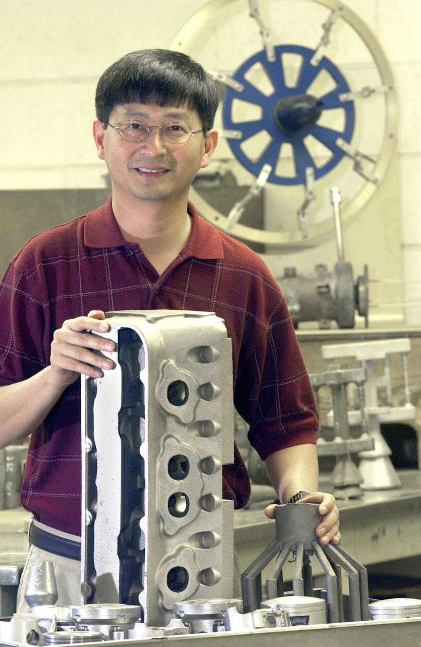
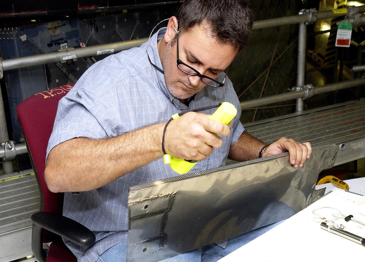
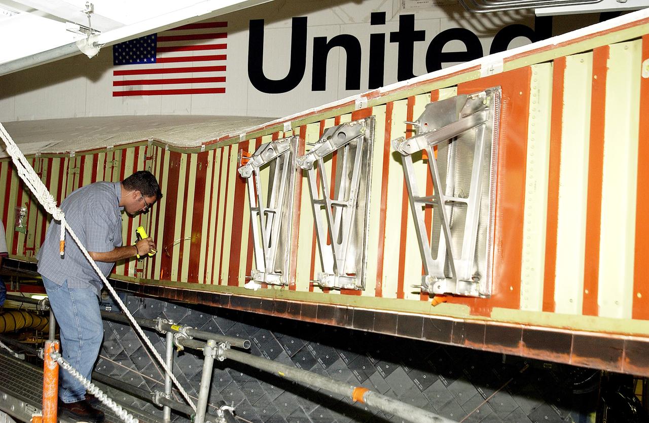
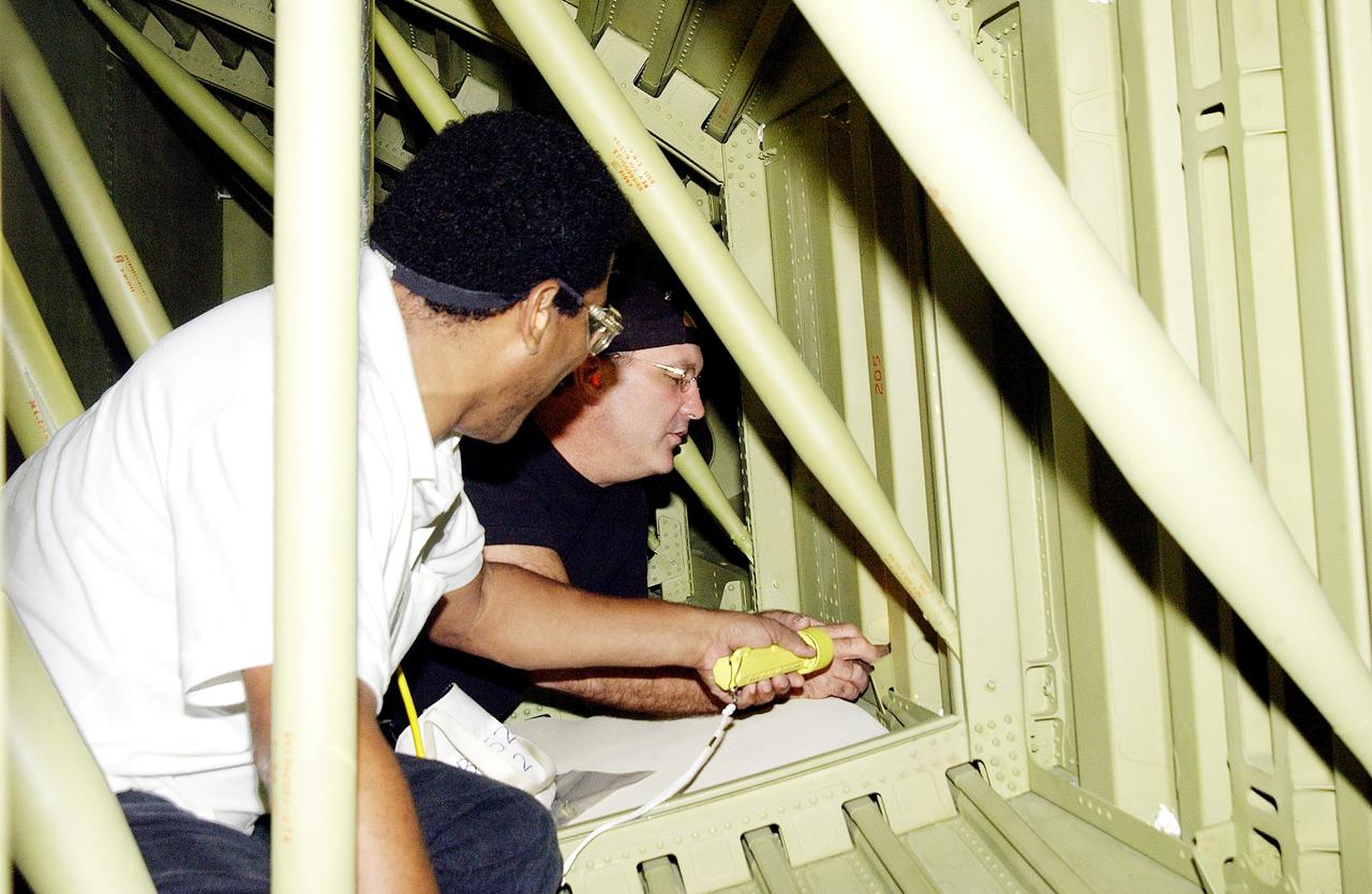
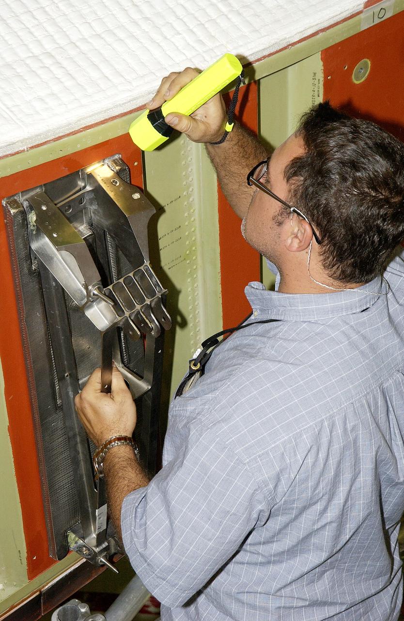
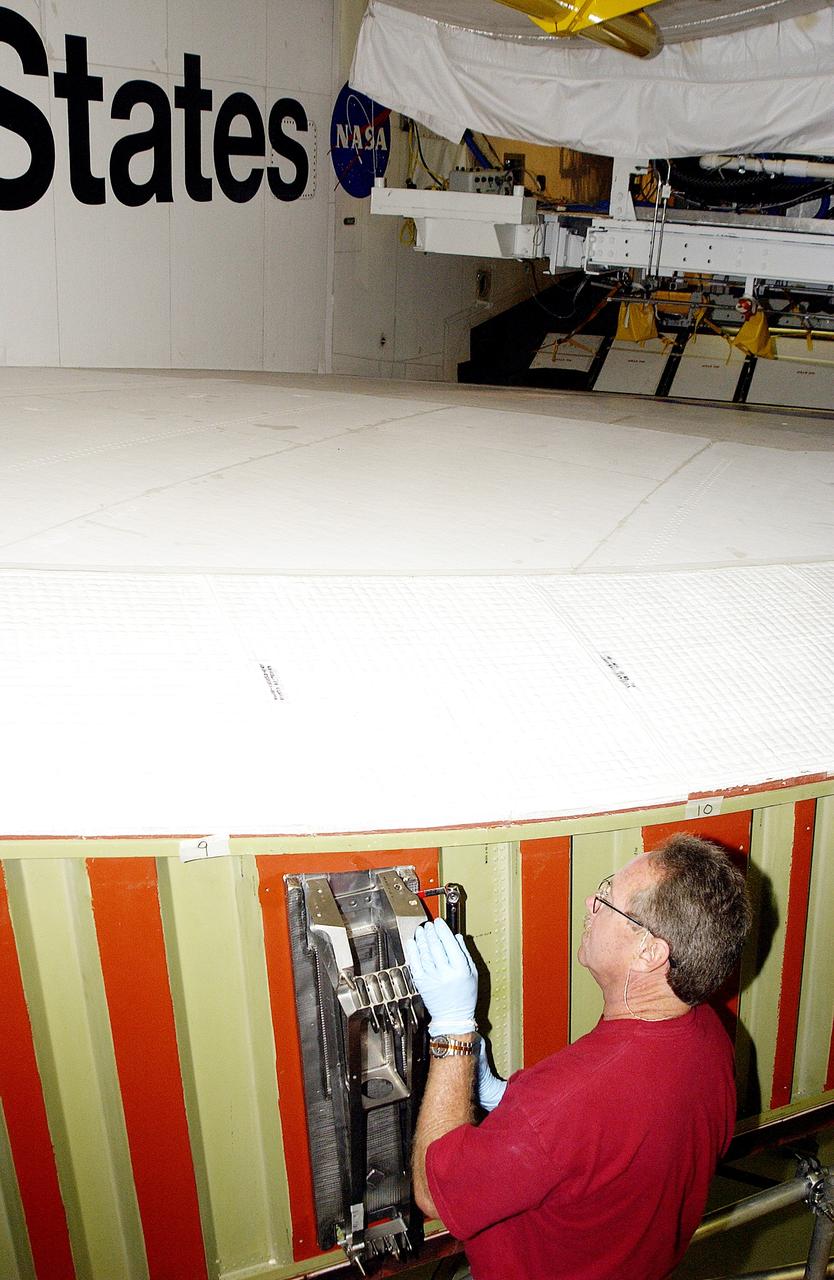
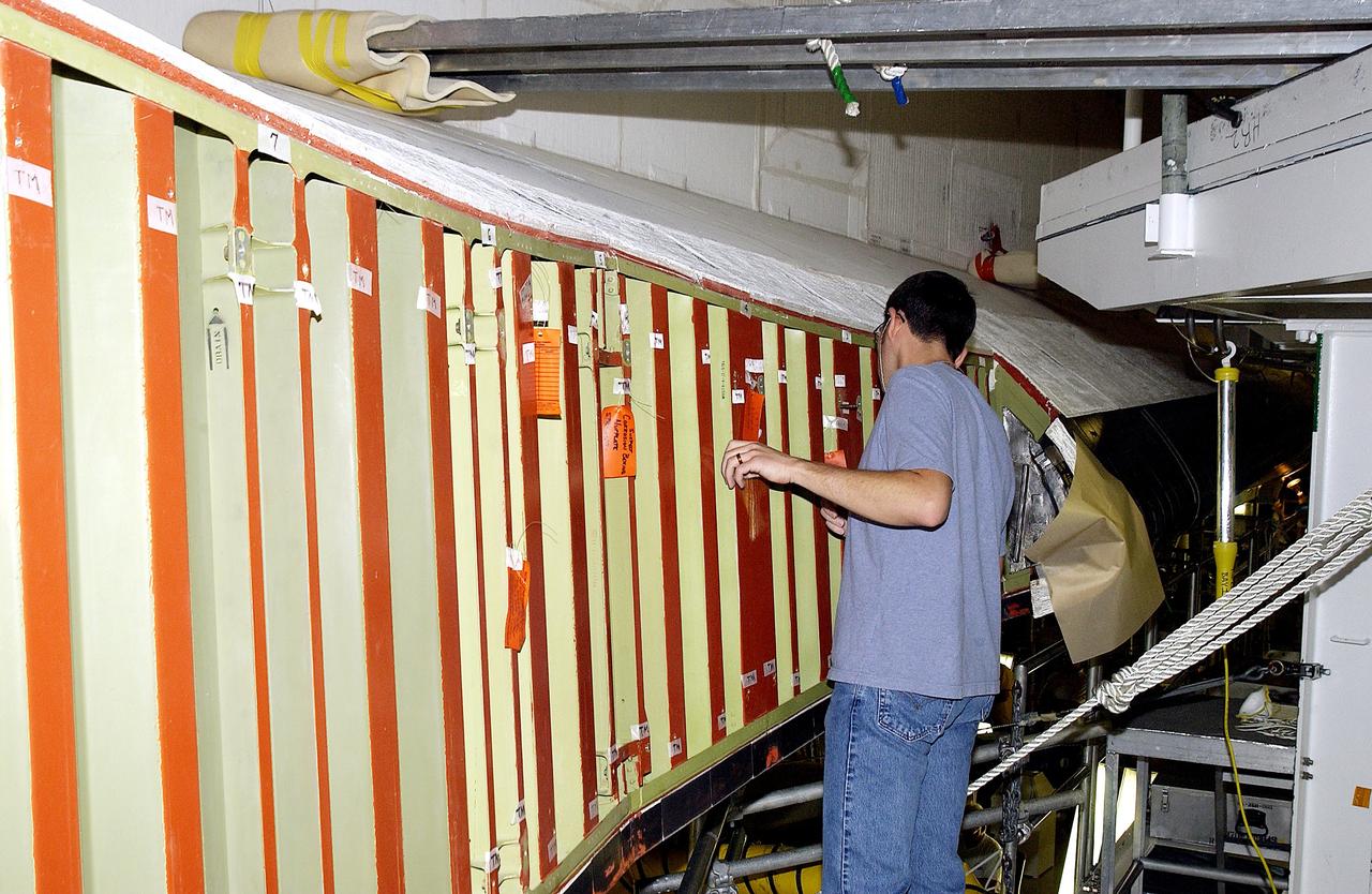
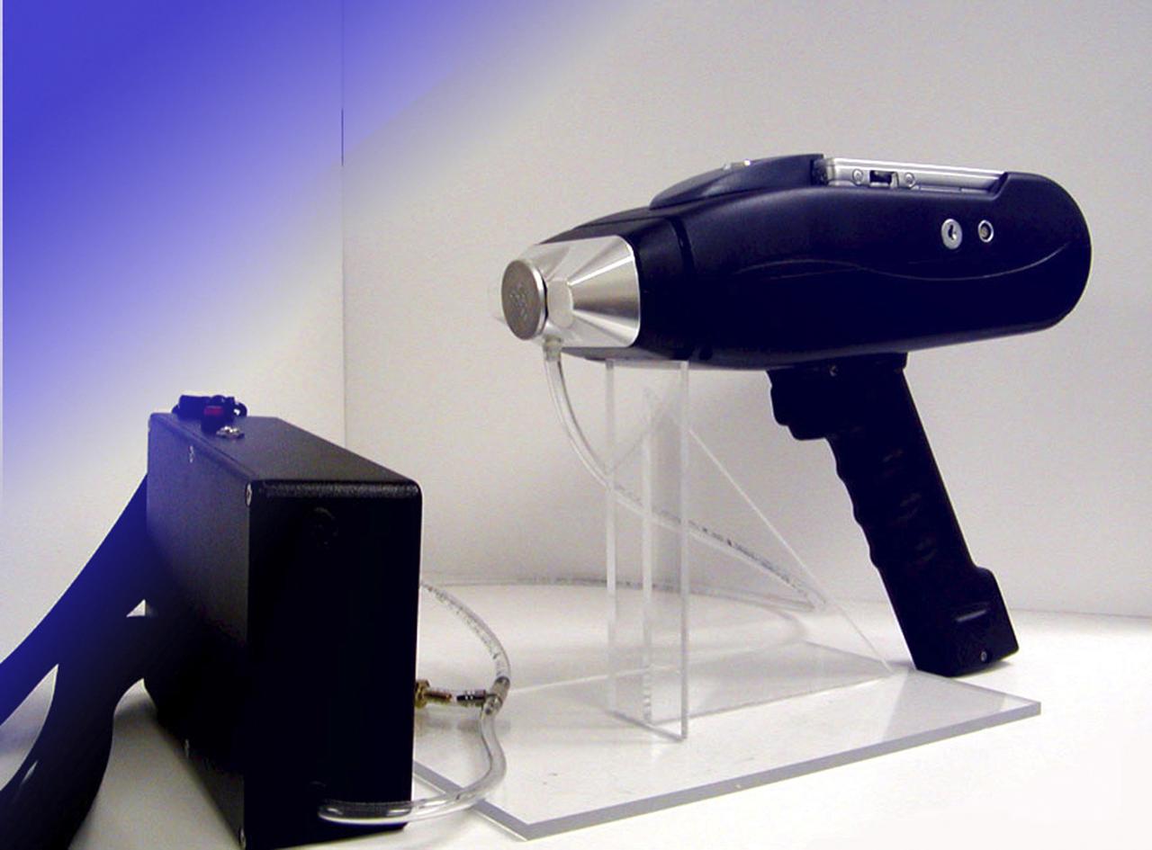
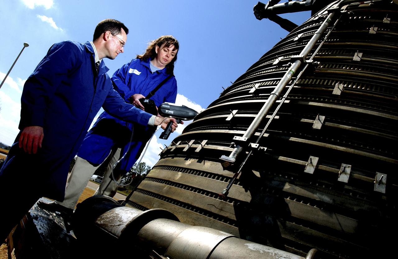
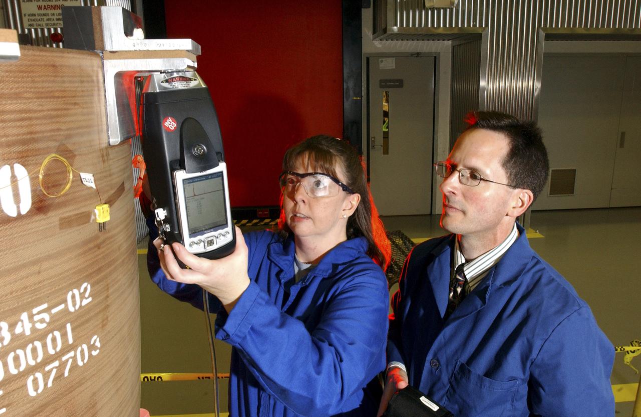
Benefit from NASA
Teamed with KeyMaster Technologies, Kennewick, Washington, the Marshall Space Flight Center engineers have developed a portable vacuum analyzer that performs on-the-spot chemical analyses under field conditions— a task previously only possible in a chemical laboratory. The new capability is important not only to the aerospace industry, but holds potential for broad applications in any industry that depends on materials analysis, such as the automotive and pharmaceutical industries. Weighing in at a mere 4 pounds, the newly developed handheld vacuum X-ray fluorescent analyzer can identify and characterize a wide range of elements, and is capable of detecting chemical elements with low atomic numbers, such as sodium, aluminum and silicon. It is the only handheld product on the market with that capability. Aluminum alloy verification is of particular interest to NASA because vast amounts of high-strength aluminum alloys are used in the Space Shuttle propulsion system such as the External Tank, Main Engine, and Solid Rocket Boosters. This capability promises to be a boom to the aerospace community because of unique requirements, for instance, the need to analyze Space Shuttle propulsion systems on the launch pad. Those systems provide the awe-inspiring rocket power that propels the Space Shuttle from Earth into orbit in mere minutes. The scanner development also marks a major improvement in the quality assurance field, because screws, nuts, bolts, fasteners, and other items can now be evaluated upon receipt and rejected if found to be substandard. The same holds true for aluminum weld rods.  The ability to validate the integrity of raw materials and partially finished products before adding value to them in the manufacturing process will be of benefit not only to businesses, but also to the consumer, who will have access to a higher value product at a cheaper price. Three vacuum X-ray scanners are already being used in the Space Shuttle Program. The External Tank Project Office is using one for aluminum alloy analysis, while a Marshall contractor is evaluating alloys with another unit purchased for the Space Shuttle Main Engine Office. The Reusable Solid Rocket Motor Project Office has obtained a scanner that is being used to test hardware and analyze materials. In this photograph, Wanda Hudson, left, ATK Thiokol, and Richard Booth, Marshall Engineering Directorate, use an enhanced vacuum X-ray fluorescent scanner to evaluate Reusable Solid Rocket Motor hardware.
Benefit from NASA
KENNEDY SPACE CENTER, FLA. - In the Orbiter Processing Facility, one of two orbital maneuvering system (OMS) pods is being moved for installation on Atlantis.  The OMS pods are attached to the upper aft fuselage left and right sides. Fabricated primarily of graphite epoxy composite and aluminum, each pod is 21.8 feet long and 11.37 feet wide at its aft end and 8.41 feet wide at its forward end, with a surface area of approximately 435 square feet. Each pod houses the Reaction Control System propulsion components used for inflight maneuvering and is attached to the aft fuselage with 11 bolts.
KENNEDY SPACE CENTER, FLA. - In the Orbiter Processing Facility, one of two orbital maneuvering system (OMS) pods is being moved for installation on Atlantis. The OMS pods are attached to the upper aft fuselage left and right sides. Fabricated primarily of graphite epoxy composite and aluminum, each pod is 21.8 feet long and 11.37 feet wide at its aft end and 8.41 feet wide at its forward end, with a surface area of approximately 435 square feet. Each pod houses the Reaction Control System propulsion components used for inflight maneuvering and is attached to the aft fuselage with 11 bolts.
KENNEDY SPACE CENTER, FLA. - In the Orbiter Processing Facility, technicians move an orbital maneuvering system (OMS) pod into the correct position on Atlantis. The OMS pod is one of two that are attached to the upper aft fuselage left and right sides. Fabricated primarily of graphite epoxy composite and aluminum, each pod is 21.8 feet long and 11.37 feet wide at its aft end and 8.41 feet wide at its forward end, with a surface area of approximately 435 square feet. Each pod houses the Reaction Control System propulsion components used for inflight maneuvering and is attached to the aft fuselage with 11 bolts.
KENNEDY SPACE CENTER, FLA. - In the Orbiter Processing Facility, an orbital maneuvering system (OMS) pod is moved into place on Atlantis.  It is one of two OMS pods attached to the upper aft fuselage left and right sides. Fabricated primarily of graphite epoxy composite and aluminum, each pod is 21.8 feet long and 11.37 feet wide at its aft end and 8.41 feet wide at its forward end, with a surface area of approximately 435 square feet. Each pod houses the Reaction Control System propulsion components used for inflight maneuvering and is attached to the aft fuselage with 11 bolts.
KENNEDY SPACE CENTER, FLA. - In the Orbiter Processing Facility, an orbital maneuvering system (OMS) pod is moved into place on Atlantis. It is one of two OMS pods attached to the upper aft fuselage left and right sides. Fabricated primarily of graphite epoxy composite and aluminum, each pod is 21.8 feet long and 11.37 feet wide at its aft end and 8.41 feet wide at its forward end, with a surface area of approximately 435 square feet. Each pod houses the Reaction Control System propulsion components used for inflight maneuvering and is attached to the aft fuselage with 11 bolts.
KENNEDY SPACE CENTER, FLA. - In the Orbiter Processing Facility, workers discuss the next step in moving the orbital maneuvering system (OMS) pod behind them.  The OMS pod will be installed on Atlantis.  Two OMS pods are attached to the upper aft fuselage left and right sides. Fabricated primarily of graphite epoxy composite and aluminum, each pod is 21.8 feet long and 11.37 feet wide at its aft end and 8.41 feet wide at its forward end, with a surface area of approximately 435 square feet. Each pod houses the Reaction Control System propulsion components used for inflight maneuvering and is attached to the aft fuselage with 11 bolts.
KENNEDY SPACE CENTER, FLA. - In the Orbiter Processing Facility, workers discuss the next step in moving the orbital maneuvering system (OMS) pod behind them. The OMS pod will be installed on Atlantis. Two OMS pods are attached to the upper aft fuselage left and right sides. Fabricated primarily of graphite epoxy composite and aluminum, each pod is 21.8 feet long and 11.37 feet wide at its aft end and 8.41 feet wide at its forward end, with a surface area of approximately 435 square feet. Each pod houses the Reaction Control System propulsion components used for inflight maneuvering and is attached to the aft fuselage with 11 bolts.
KENNEDY SPACE CENTER, FLA. -  In the Orbiter Processing Facility, one of two orbital maneuvering system (OMS) pods is lifted off its stand to move it toward Atlantis for installation. The OMS pods are attached to the upper aft fuselage left and right sides. Fabricated primarily of graphite epoxy composite and aluminum, each pod is 21.8 feet long and 11.37 feet wide at its aft end and 8.41 feet wide at its forward end, with a surface area of approximately 435 square feet. Each pod houses the Reaction Control System propulsion components used for inflight maneuvering and is attached to the aft fuselage with 11 bolts.
KENNEDY SPACE CENTER, FLA. - In the Orbiter Processing Facility, one of two orbital maneuvering system (OMS) pods is lifted off its stand to move it toward Atlantis for installation. The OMS pods are attached to the upper aft fuselage left and right sides. Fabricated primarily of graphite epoxy composite and aluminum, each pod is 21.8 feet long and 11.37 feet wide at its aft end and 8.41 feet wide at its forward end, with a surface area of approximately 435 square feet. Each pod houses the Reaction Control System propulsion components used for inflight maneuvering and is attached to the aft fuselage with 11 bolts.
KENNEDY SPACE CENTER, FLA. - In the Orbiter Processing Facility, technicians make final adjustments to the orbital maneuvering system (OMS) pod being installed on Atlantis.   The OMS pod is one of two that are attached to the upper aft fuselage left and right sides. Fabricated primarily of graphite epoxy composite and aluminum, each pod is 21.8 feet long and 11.37 feet wide at its aft end and 8.41 feet wide at its forward end, with a surface area of approximately 435 square feet. Each pod houses the Reaction Control System propulsion components used for inflight maneuvering and is attached to the aft fuselage with 11 bolts.
KENNEDY SPACE CENTER, FLA. - In the Orbiter Processing Facility, technicians make final adjustments to the orbital maneuvering system (OMS) pod being installed on Atlantis. The OMS pod is one of two that are attached to the upper aft fuselage left and right sides. Fabricated primarily of graphite epoxy composite and aluminum, each pod is 21.8 feet long and 11.37 feet wide at its aft end and 8.41 feet wide at its forward end, with a surface area of approximately 435 square feet. Each pod houses the Reaction Control System propulsion components used for inflight maneuvering and is attached to the aft fuselage with 11 bolts.
KENNEDY SPACE CENTER, FLA. - In the Orbiter Processing Facility, one of two orbital maneuvering system (OMS) pods is being moved for installation on Atlantis.  The OMS pods are attached to the upper aft fuselage left and right sides. Fabricated primarily of graphite epoxy composite and aluminum, each pod is 21.8 feet long and 11.37 feet wide at its aft end and 8.41 feet wide at its forward end, with a surface area of approximately 435 square feet. Each pod houses the Reaction Control System propulsion components used for inflight maneuvering and is attached to the aft fuselage with 11 bolts.
KENNEDY SPACE CENTER, FLA. - In the Orbiter Processing Facility, one of two orbital maneuvering system (OMS) pods is being moved for installation on Atlantis. The OMS pods are attached to the upper aft fuselage left and right sides. Fabricated primarily of graphite epoxy composite and aluminum, each pod is 21.8 feet long and 11.37 feet wide at its aft end and 8.41 feet wide at its forward end, with a surface area of approximately 435 square feet. Each pod houses the Reaction Control System propulsion components used for inflight maneuvering and is attached to the aft fuselage with 11 bolts.
KENNEDY SPACE CENTER, FLA. - In the Orbiter Processing Facility, technicians make adjustments to the orbital maneuvering system (OMS) pod being installed on Atlantis.   The OMS pod is one of two that are attached to the upper aft fuselage left and right sides. Fabricated primarily of graphite epoxy composite and aluminum, each pod is 21.8 feet long and 11.37 feet wide at its aft end and 8.41 feet wide at its forward end, with a surface area of approximately 435 square feet. Each pod houses the Reaction Control System propulsion components used for inflight maneuvering and is attached to the aft fuselage with 11 bolts.
KENNEDY SPACE CENTER, FLA. - In the Orbiter Processing Facility, technicians make adjustments to the orbital maneuvering system (OMS) pod being installed on Atlantis. The OMS pod is one of two that are attached to the upper aft fuselage left and right sides. Fabricated primarily of graphite epoxy composite and aluminum, each pod is 21.8 feet long and 11.37 feet wide at its aft end and 8.41 feet wide at its forward end, with a surface area of approximately 435 square feet. Each pod houses the Reaction Control System propulsion components used for inflight maneuvering and is attached to the aft fuselage with 11 bolts.
KENNEDY SPACE CENTER, FLA. -  In the Orbiter Processing Facility, an orbital maneuvering system (OMS) pod is moved closer to Atlantis for installation.  Two OMS pods are attached to the upper aft fuselage left and right sides. Fabricated primarily of graphite epoxy composite and aluminum, each pod is 21.8 feet long and 11.37 feet wide at its aft end and 8.41 feet wide at its forward end, with a surface area of approximately 435 square feet. Each pod houses the Reaction Control System propulsion components used for inflight maneuvering and is attached to the aft fuselage with 11 bolts.
KENNEDY SPACE CENTER, FLA. - In the Orbiter Processing Facility, an orbital maneuvering system (OMS) pod is moved closer to Atlantis for installation. Two OMS pods are attached to the upper aft fuselage left and right sides. Fabricated primarily of graphite epoxy composite and aluminum, each pod is 21.8 feet long and 11.37 feet wide at its aft end and 8.41 feet wide at its forward end, with a surface area of approximately 435 square feet. Each pod houses the Reaction Control System propulsion components used for inflight maneuvering and is attached to the aft fuselage with 11 bolts.
KENNEDY SPACE CENTER, FLA. -  In the Orbiter Processing Facility, an orbital maneuvering system (OMS) pod is suspended in air as it is moved toward Atlantis for installation.  Two OMS pods are attached to the upper aft fuselage left and right sides. Fabricated primarily of graphite epoxy composite and aluminum, each pod is 21.8 feet long and 11.37 feet wide at its aft end and 8.41 feet wide at its forward end, with a surface area of approximately 435 square feet. Each pod houses the Reaction Control System propulsion components used for inflight maneuvering and is attached to the aft fuselage with 11 bolts.
KENNEDY SPACE CENTER, FLA. - In the Orbiter Processing Facility, an orbital maneuvering system (OMS) pod is suspended in air as it is moved toward Atlantis for installation. Two OMS pods are attached to the upper aft fuselage left and right sides. Fabricated primarily of graphite epoxy composite and aluminum, each pod is 21.8 feet long and 11.37 feet wide at its aft end and 8.41 feet wide at its forward end, with a surface area of approximately 435 square feet. Each pod houses the Reaction Control System propulsion components used for inflight maneuvering and is attached to the aft fuselage with 11 bolts.
KENNEDY SPACE CENTER, FLA. -  In the Orbiter Processing Facility, technicians move an orbital maneuvering system (OMS) pod into the correct position on Atlantis. The OMS pod is one of two that are attached to the upper aft fuselage left and right sides. Fabricated primarily of graphite epoxy composite and aluminum, each pod is 21.8 feet long and 11.37 feet wide at its aft end and 8.41 feet wide at its forward end, with a surface area of approximately 435 square feet. Each pod houses the Reaction Control System propulsion components used for inflight maneuvering and is attached to the aft fuselage with 11 bolts.
KENNEDY SPACE CENTER, FLA. - In the Orbiter Processing Facility, technicians move an orbital maneuvering system (OMS) pod into the correct position on Atlantis. The OMS pod is one of two that are attached to the upper aft fuselage left and right sides. Fabricated primarily of graphite epoxy composite and aluminum, each pod is 21.8 feet long and 11.37 feet wide at its aft end and 8.41 feet wide at its forward end, with a surface area of approximately 435 square feet. Each pod houses the Reaction Control System propulsion components used for inflight maneuvering and is attached to the aft fuselage with 11 bolts.
KENNEDY SPACE CENTER, FLA. - In the Orbiter Processing Facility, an orbital maneuvering system (OMS) pod is moved into place on Atlantis.  It is one of two OMS pods attached to the upper aft fuselage left and right sides. Fabricated primarily of graphite epoxy composite and aluminum, each pod is 21.8 feet long and 11.37 feet wide at its aft end and 8.41 feet wide at its forward end, with a surface area of approximately 435 square feet. Each pod houses the Reaction Control System propulsion components used for inflight maneuvering and is attached to the aft fuselage with 11 bolts.
KENNEDY SPACE CENTER, FLA. - In the Orbiter Processing Facility, an orbital maneuvering system (OMS) pod is moved into place on Atlantis. It is one of two OMS pods attached to the upper aft fuselage left and right sides. Fabricated primarily of graphite epoxy composite and aluminum, each pod is 21.8 feet long and 11.37 feet wide at its aft end and 8.41 feet wide at its forward end, with a surface area of approximately 435 square feet. Each pod houses the Reaction Control System propulsion components used for inflight maneuvering and is attached to the aft fuselage with 11 bolts.
This graph depicts the increased signal quality possible with optical fibers made from ZBLAN, a family of heavy-metal fluoride glasses (fluorine combined zirconium, barium, lanthanum, aluminum, and sodium) as compared to silica fibers. NASA is conducting research on pulling ZBLAN fibers in the low-g environment of space to prevent crystallization that limits ZBLAN's usefulness in optical fiber-based communications. In the graph, a line closer to the black theoretical maximum line is better. Photo credit: NASA/Marshall Space Flight Center
Microgravity
At NASA's Kennedy Space Center in Florida, Public Affairs Officer George Diller digs in behind the current countdown clock during the groundbreaking ceremony for the new countdown clock. The old timepiece was designed by Kennedy engineers and built by Kennedy technicians in 1969. Not including the triangular concrete and aluminum base, the famous landmark is nearly 6 feet 70 inches high, 26 feet 315 inches wide and 3 feet deep. The new display will be similar in size, with the screen being nearly 26 feet wide by 7 feet high.
New Countdown Clock
jsc2021e066969 (8/18/2021) --- A preflight image of three kinds of substrates (Diamond, Sapphire, Silicon) on the aluminum carrier. The purpose of the Artificial Diamond Substrate Exposure Experiment in Space investigation is to see how a KENZAN Diamond™ substrate could be affected by severe environments such as outer space. The results can help researchers identify the elements necessary for diamond substrate applications expected in aerospace and next generation semiconductors, as well as improve their quality and reliability. Image Credit: Adamant Namiki Precision Jewel Co., Ltd..
jsc2021e066969
Workers sign the banner marking the successful delivery of a liquid oxygen test tank, called Tardis, in the Prototype Development Laboratory at NASA's Kennedy Space Center in Florida. Engineers and technicians worked together to develop the tank and build it at the lab to support cryogenic testing at Johnson Space Center's White Sands Test Facility in Las Cruces, New Mexico. The 12-foot-tall, 3,810-pound aluminum tank will be shipped to White Sands for testing.
NE TARDIS Banner Event
A machine cuts, rotates, and turns a block of aluminum to make a forward wing strut fastener for a 10-foot model of the Transonic Truss-Braced Wing at NASA’s Armstrong Flight Research Center, in Edwards, California. The aircraft concept involves a wing braced on an aircraft using diagonal struts that also add lift and could result in significantly improved aerodynamics.
NASA Armstrong Builds Model Wing
JSC2003-E-42601 (June 2003) --- Astronaut Nancy J. Currie, wearing a training version of an advanced concept space suit, shakes hands with a Robonaut prior to participating in a test at the Johnson Space Center to evaluate hand-in-hand work with robots. The second of the two Robonauts used in the demonstration's task -- the assembly of an aluminum truss structure--is out of frame.
Robonaut joint task operations with astronaut Nancy Currie.
Inside the Prototype Development Laboratory at NASA's Kennedy Space Center in Florida, workers in the lab hold a banner marking the successful delivery of a liquid oxygen test tank called Tardis. Engineers and technicians worked together to develop the tank to build it at the lab to support cryogenic testing at Johnson Space Center's White Sands Test Facility in Las Cruces, New Mexico. The 12-foot-tall, 3,810-pound aluminum tank will be shipped to White Sands for testing.
NE TARDIS Banner Event
KENNEDY SPACE CENTER, FLA. -  In the Orbiter Processing Facility, A Hyster forklift supports the body flap as workers secure it to the orbiter Discovery. The body flap is an aluminum structure consisting of ribs, spars, skin panels and a trailing edge assembly. It thermally shields the three main engines during entry and provides pitch control trim during landing approach. Discovery is being processed for launch on the first Return to Flight mission, STS-114.
KSC-04pd0460
This close-up view of the United States flag plate on NASA's Perseverance was acquired on June 28, 2025 (the 1,548th day, or sol, of its mission to Mars), by the WATSON (Wide Angle Topographic Sensor for Operations and eNgineering) imager on the turret at the end of the rover's Mars robotic arm.  This flag artwork is located on an aluminum plate mounted on the base of Perseverance's remote sensing mast.  https://photojournal.jpl.nasa.gov/catalog/PIA26579
Old Glory on the Red Planet
This close-up view of a plate on NASA's Perseverance rover commemorating the impact of the COVID-19 pandemic and paying tribute to the perseverance of health care workers around the world was acquired on June 28, 2025 (the 1,548th day, or sol, of its mission to Mars).  Located on the left side of the rover chassis, the 3-by-5-inch (8-by-13-centimeter) aluminum plaque was attached in May 2020 during final assembly at NASA's Kennedy Space Center in Florida.  https://photojournal.jpl.nasa.gov/catalog/PIA26641
A Martian Tribute on Perseverance
iss066e078285 (Nov. 17, 2021) --- International Space Station Commander Anton Shkaplerov of Roscosmos (from left) and NASA astronaut and Expedition 66 Flight Engineer Thomas Marshburn work on the SUBSA-BRAINS (BRazing of Aluminum alloys IN Space) space physics experiment taking place inside the Microgravity Science Glovebox. The study examines differences in capillary flow, interface reactions, and bubble formation during solidification of brazing alloys in microgravity.
iss066e078285
KENNEDY SPACE CENTER, FLA. -  A Hyster forklift in the Orbiter Processing Facility lifts the body flap to be installed on the orbiter Discovery. The body flap is an aluminum structure consisting of ribs, spars, skin panels and a trailing edge assembly. It thermally shields the three main engines during entry and provides pitch control trim during landing approach.  Discovery is being processed for launch on the first Return to Flight mission, STS-114.
KSC-04pd0454
KENNEDY SPACE CENTER, FLA. -  In the Orbiter Processing Facility, the body flap for the orbiter Discovery is prepared for installation. The body flap is an aluminum structure consisting of ribs, spars, skin panels and a trailing edge assembly. It thermally shields the three main engines during entry and provides pitch control trim during landing approach.  Discovery is being processed for launch on the first Return to Flight mission, STS-114.
KSC-04pd0452
This wheel, and five others just like it, is headed to Mars on NASA's Perseverance rover; the launch window opens July 17, 2020. Wrapped in a protective antistatic foil that will be removed before launch, the wheel is 20.7 inches (52.6 centimeters) in diameter and machined from a solid block of aluminum; the spokes are titanium. The image was taken on March 30, 2020, at a payload processing facility at NASA's Kennedy Space Center in Florida.  https://photojournal.jpl.nasa.gov/catalog/PIA23822
Gift Wrapped Mars Wheel
jsc2024e081749 (3/18/2023) --- LignoSat structural internal view shows the relationship among wooden panels, aluminum frames, and stainless steel shafts. LignoSat is the world’s first wooden satellite and investigates how wood changes in the space environment, as well as how wood transmits data through geomagnetic fields and wood’s resistance to cosmic radiation. Image courtesy of Kyoto University.
jsc2024e081749
KENNEDY SPACE CENTER, FLA. -  Workers in the Orbiter Processing Facility lean toward the body flap to be installed on the orbiter Discovery.  The body flap is an aluminum structure consisting of ribs, spars, skin panels and a trailing edge assembly. It thermally shields the three main engines during entry and provides pitch control trim during landing approach.  Discovery is being processed for launch on the first Return to Flight mission, STS-114.
KSC-04pd0458
KENNEDY SPACE CENTER, FLA. -  A Hyster forklift in the Orbiter Processing Facility moves the body flap toward the aft of the orbiter Discovery. The body flap is an aluminum structure consisting of ribs, spars, skin panels and a trailing edge assembly. It thermally shields the three main engines during entry and provides pitch control trim during landing approach.  Discovery is being processed for launch on the first Return to Flight mission, STS-114.
KSC-04pd0455
jsc2022e042616 (5/20/2022) --- The EMIT instrument before the enclosure panels were attached. The long tube in the foreground is the EMIT telescope baffle. The telescope resides in the large aluminum cube behind the baffle, and the spectrometer assembly is attached to the back of the telescope. The entire assembly is called the Optical Bench Assembly, or OBA. The OBA sits above the Electronics Mounting Plate, which is home to all of the instrument electronics and the cryocooler (not visible). Image courtesy of JPL.
jsc2022e042616
A liquid oxygen test tank was completed in the Prototype Development Laboratory at NASA's Kennedy Space Center in Florida. A banner signing event marked the successful delivery of the tank called Tardis.  Engineers and technicians worked together to develop the tank and build it at the lab to support cryogenic testing at Johnson Space Center's White Sands Test Facility in Las Cruces, New Mexico. The 12-foot-tall, 3,810-pound aluminum tank will be shipped to White Sands for testing.
NE TARDIS Banner Event
iss066e078283 (Nov. 17, 2021) ---  International Space Station Commander Anton Shkaplerov of Roscosmos works on the SUBSA-BRAINS (BRazing of Aluminum alloys IN Space) space physics experiment taking place inside the Microgravity Science Glovebox. The study examines differences in capillary flow, interface reactions, and bubble formation during solidification of brazing alloys in microgravity.
iss066e078283
KENNEDY SPACE CENTER, FLA. -  Workers in the Orbiter Processing Facility help move the body flap into position on the orbiter Discovery.  The body flap is an aluminum structure consisting of ribs, spars, skin panels and a trailing edge assembly. It thermally shields the three main engines during entry and provides pitch control trim during landing approach.  Discovery is being processed for launch on the first Return to Flight mission, STS-114.
KSC-04pd0459
KENNEDY SPACE CENTER, FLA. -  The body flap is installed on the orbiter Discovery. The body flap is an aluminum structure consisting of ribs, spars, skin panels and a trailing edge assembly. It thermally shields the three main engines during entry and provides pitch control trim during landing approach. Discovery is being processed for launch on the first Return to Flight mission, STS-114.
KSC-04pd0464
KENNEDY SPACE CENTER, FLA. -  Workers on ladders (left and right) check installation of the body flap onto the orbiter Discovery. The body flap is an aluminum structure consisting of ribs, spars, skin panels and a trailing edge assembly. It thermally shields the three main engines during entry and provides pitch control trim during landing approach. Discovery is being processed for launch on the first Return to Flight mission, STS-114.
KSC-04pd0462
A block of aluminum is transformed by a machine programmed to cut, rotate, and turn it to make a forward wing strut fastener for a 10-foot model of the Transonic Truss-Braced Wing at NASA’s Armstrong Flight Research Center, in Edwards, California. The aircraft concept involves a wing braced on an aircraft using diagonal struts that also add lift and could result in significantly improved aerodynamics.
NASA Armstrong Builds Model Wing
NASA Kennedy Space Center's Engineering Director Pat Simpkins signs the banner marking the successful delivery of a liquid oxygen test tank, called Tardis, in the Prototype Development Laboratory at NASA's Kennedy Space Center in Florida. Engineers and technicians worked together to develop the tank and build it to support cryogenic testing at Johnson Space Center's White Stands Test Facility in Las Cruces, New Mexico. The 12-foot-tall, 3,810-pound aluminum tank will be shipped to White Sands for testing.
NE TARDIS Banner Event
KENNEDY SPACE CENTER, FLA. -  In the Orbiter Processing Facility, the body flap is moved into position for installation on the orbiter Discovery.  The body flap is an aluminum structure consisting of ribs, spars, skin panels and a trailing edge assembly. It thermally shields the three main engines during entry and provides pitch control trim during landing approach.  Discovery is being processed for launch on the first Return to Flight mission, STS-114.
KSC-04pd0456
KENNEDY SPACE CENTER, FLA. -  Workers in the Orbiter Processing Facility help prepare the body flap for lifting prior to installation on the orbiter Discovery. The body flap is an aluminum structure consisting of ribs, spars, skin panels and a trailing edge assembly. It thermally shields the three main engines during entry and provides pitch control trim during landing approach.  Discovery is being processed for launch on the first Return to Flight mission, STS-114.
KSC-04pd0453