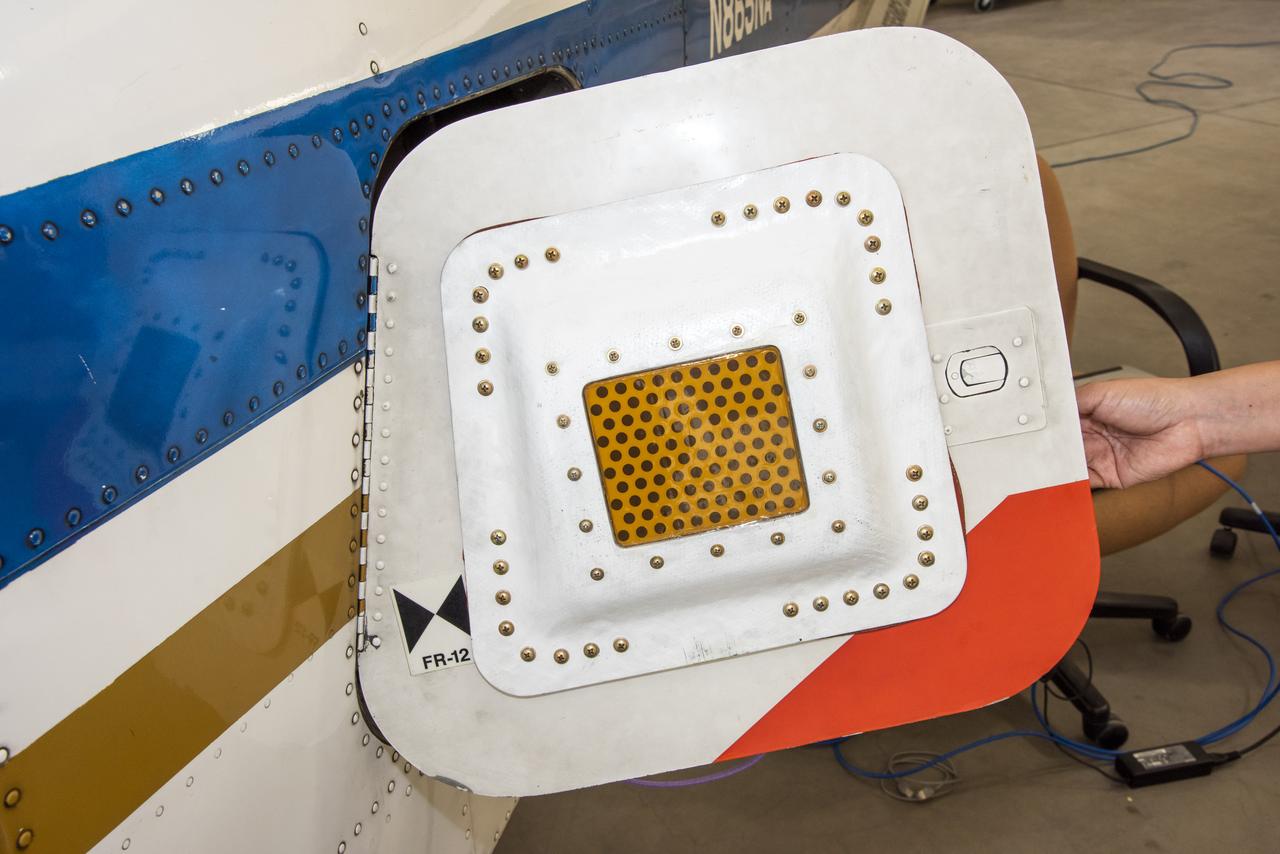
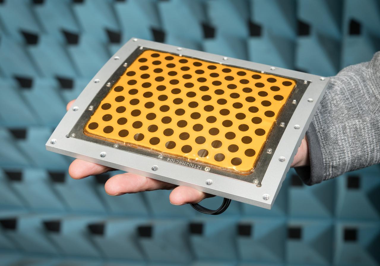
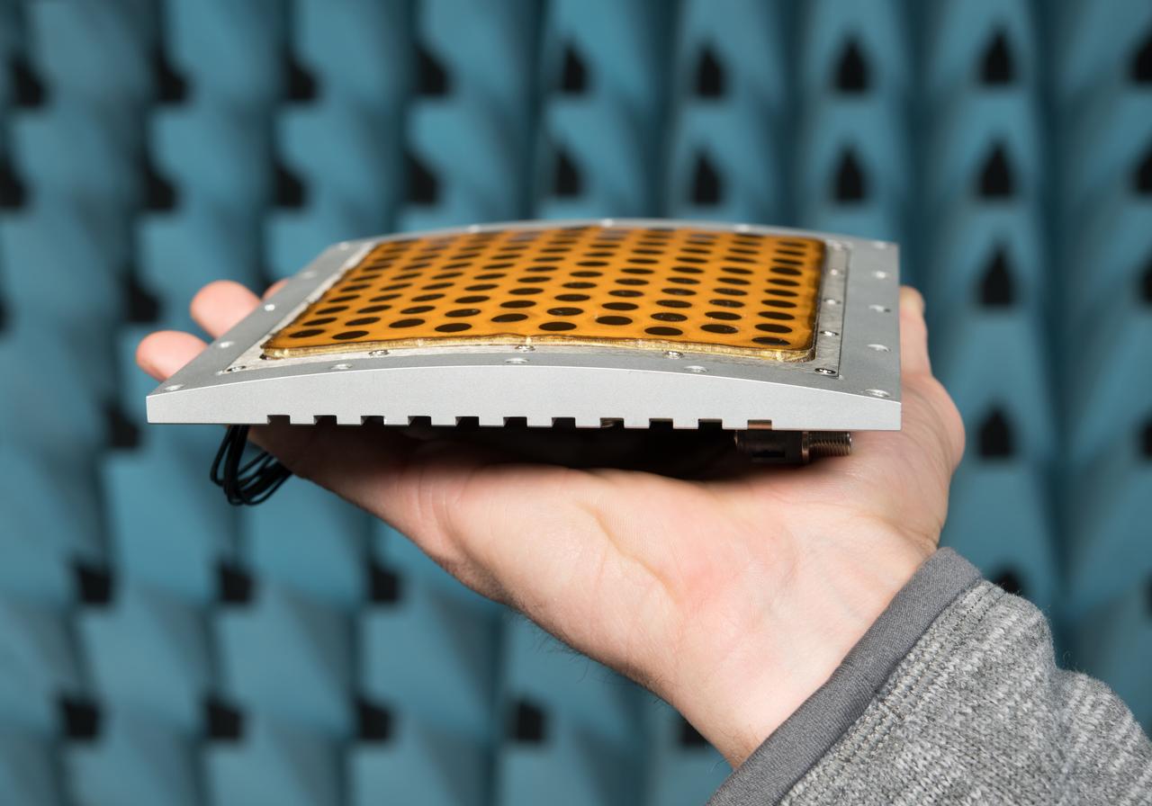
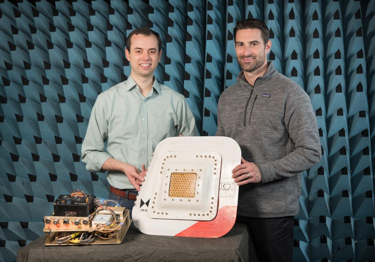
A photo of the conformal antenna installed on the door of T-34C aircraft. The conformal antenna was developed and designed by members of the Conformal Lightweight Antenna Structures for Aeronautical Communications Technologies activity within the Convergent Aeronautics Solutions project. The antenna is made of aerogels which have resulted in a thin, flexible antenna substrate with improved gain, bandwidth and efficiency.
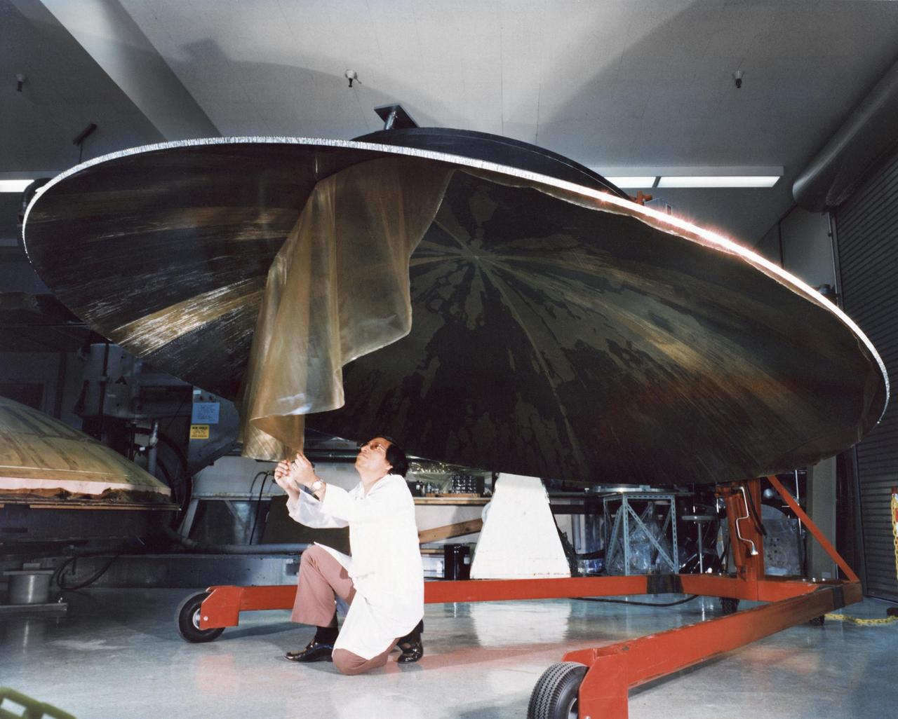
This archival photo shows an engineer working on the construction of a large, dish-shaped Voyager high-gain antenna. The picture was taken on July 9, 1976. https://photojournal.jpl.nasa.gov/catalog/PIA21480
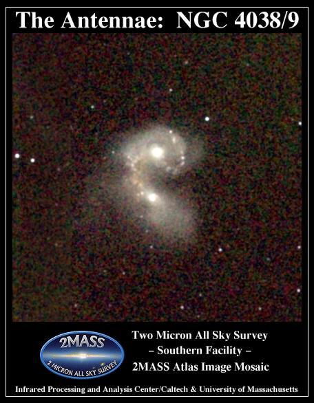
Atlas Image mosaic, covering 7 x 7 on the sky of the interacting galaxies NGC 4038 and NGC 4039, better known as the Antennae, or Ring Tail galaxies. The two galaxies are engaged in a tug-of-war as they collide.
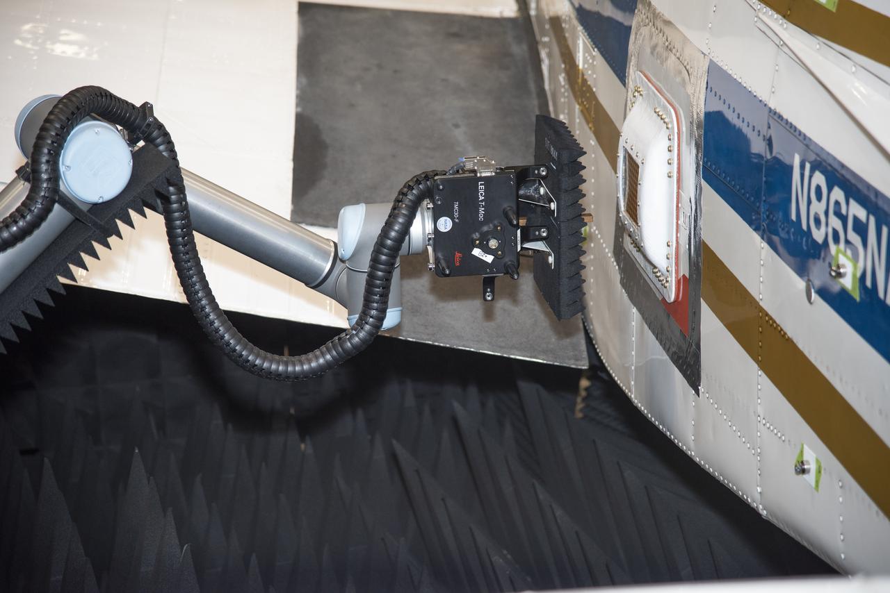
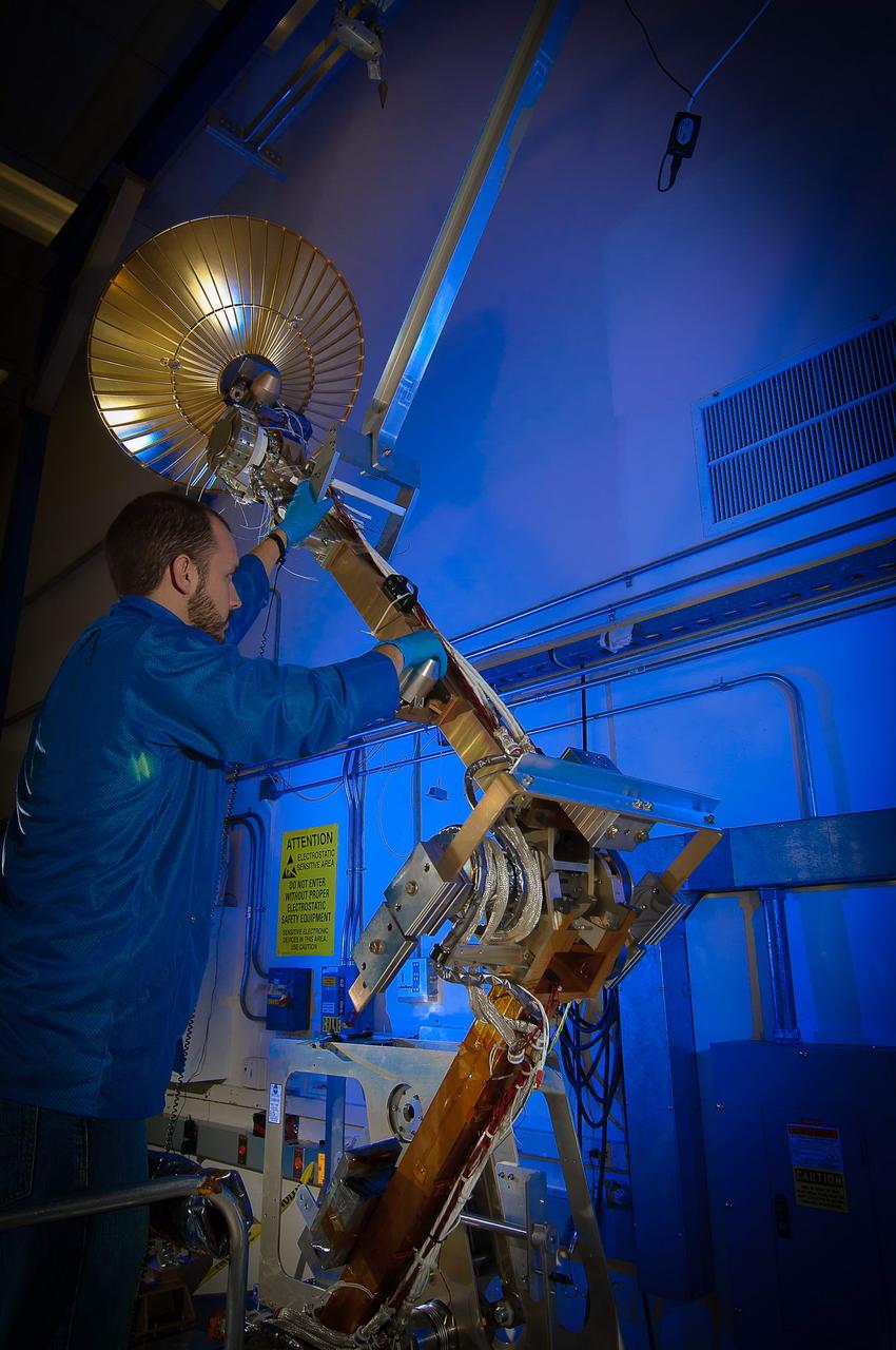
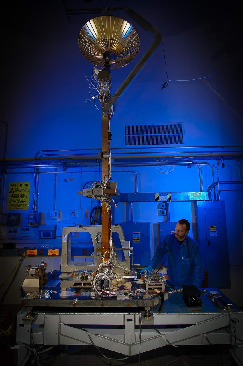
Tests were conducted with a robotic antenna scanner at NASA's Armstrong Flight Research Center in California. The scanner was used to test the in-situ radiation pattern of the conformal antenna to verify its performance parameters before being tested on an aircraft.

NASA's Armstrong Flight Research Center installed a conformal antenna on the door of its T-34C aircraft to test its performance parameters. The conformal antenna was designed through a cross-center collaboration through the Conformal Lightweight Antenna Structures for Aeronautical Communications Technologies project.

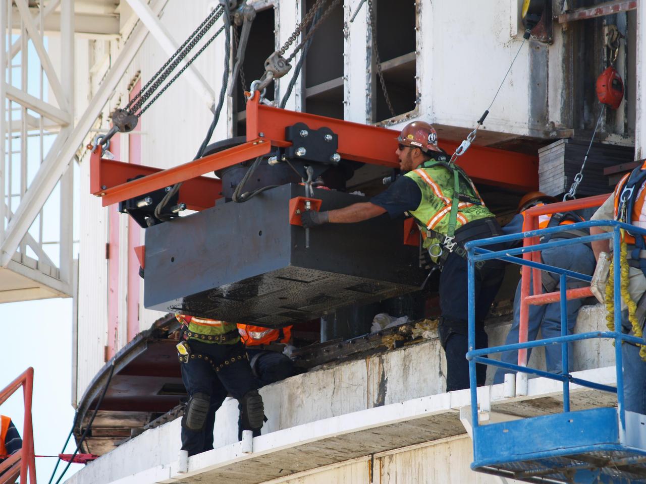
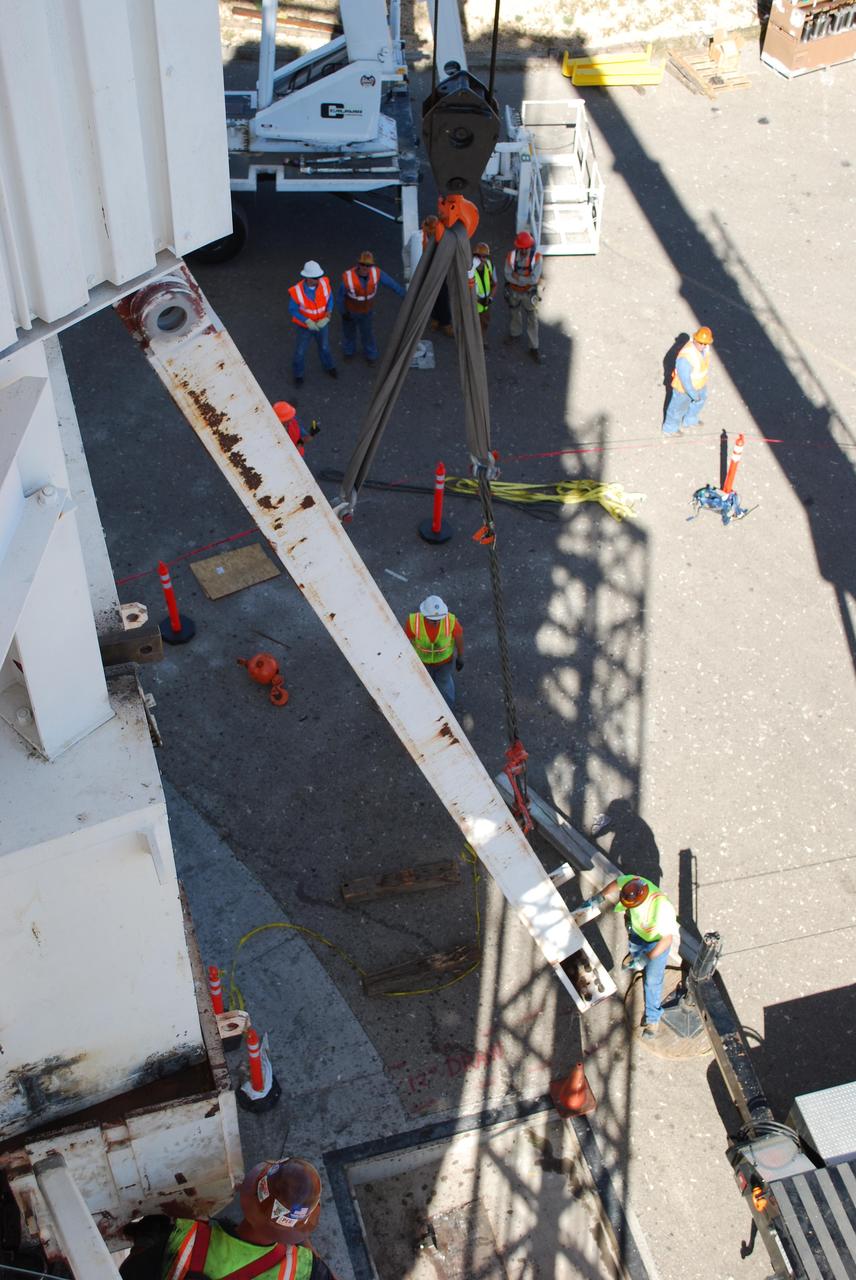
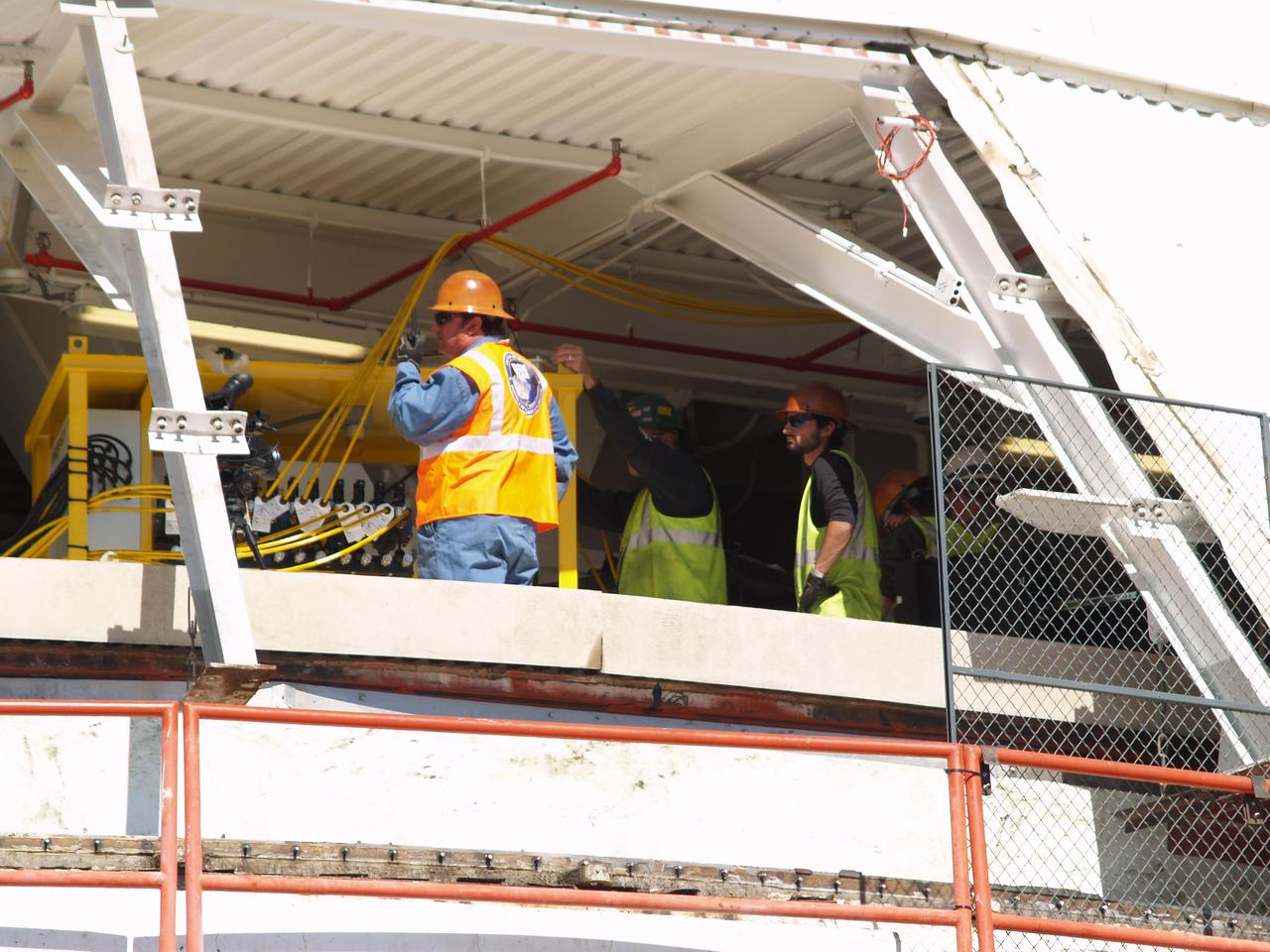
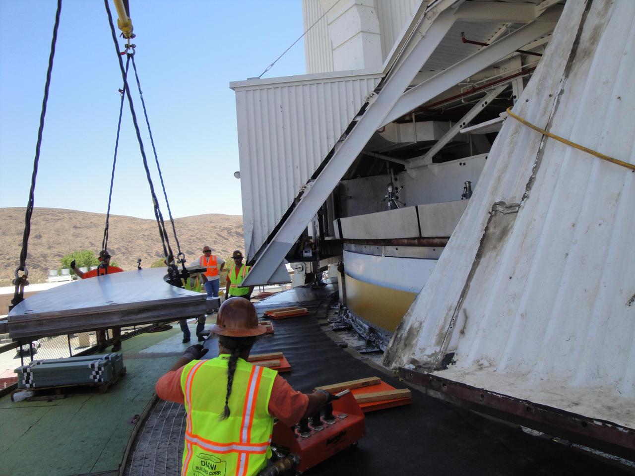
A CREW INSTALLS A NEW EARTH SCIENCE RECEIVING SATELLITE ANTENNA OUTSIDE MARSHALL SPACE FLIGHT CENTER'S ACTIVITIES BUILDING 4316

A CREW INSTALLS A NEW EARTH SCIENCE RECEIVING SATELLITE ANTENNA OUTSIDE MARSHALL SPACE FLIGHT CENTER'S ACTIVITIES BUILDING 4316

A CREW INSTALLS A NEW EARTH SCIENCE RECEIVING SATELLITE ANTENNA OUTSIDE MARSHALL SPACE FLIGHT CENTER'S ACTIVITIES BUILDING 4316

A CREW INSTALLS A NEW EARTH SCIENCE RECEIVING SATELLITE ANTENNA OUTSIDE MARSHALL SPACE FLIGHT CENTER'S ACTIVITIES BUILDING 4316
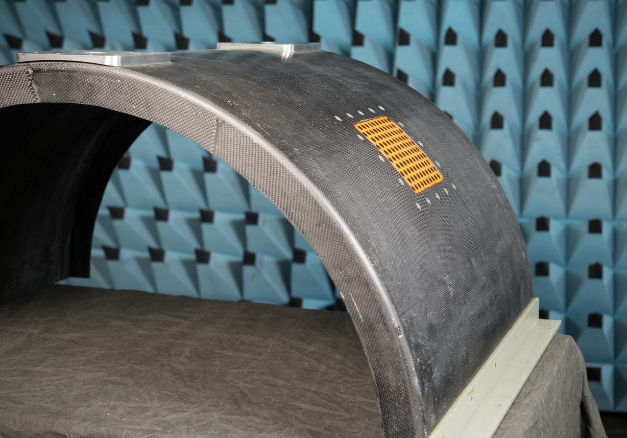
Curved Confocal Lightweight Antenna Structures for Aeronautical Communications Technologies, CLAS-ACT, Phased Array Antenna on Mock Carbon Fiber Fuselage
Curved Confocal Lightweight Antenna Structures for Aeronautical Communications Technologies, CLAS-ACT, Phased Array Antenna on Mock Carbon Fiber Fuselage
Curved Confocal Lightweight Antenna Structures for Aeronautical Communications Technologies, CLAS-ACT, Phased Array Antenna on Mock Carbon Fiber Fuselage
Forward Ramp & Low Gain Antenna
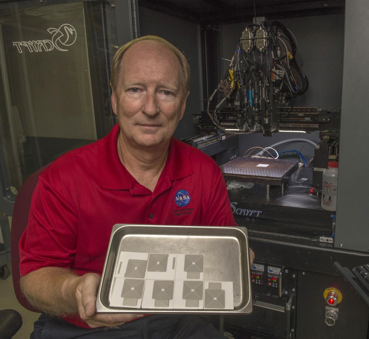
Curtis Hill (EM32/ESSSA) shows recently printed silver antenna arrays with Marshall’s nScrypt® Multi-Material Deposition System (background
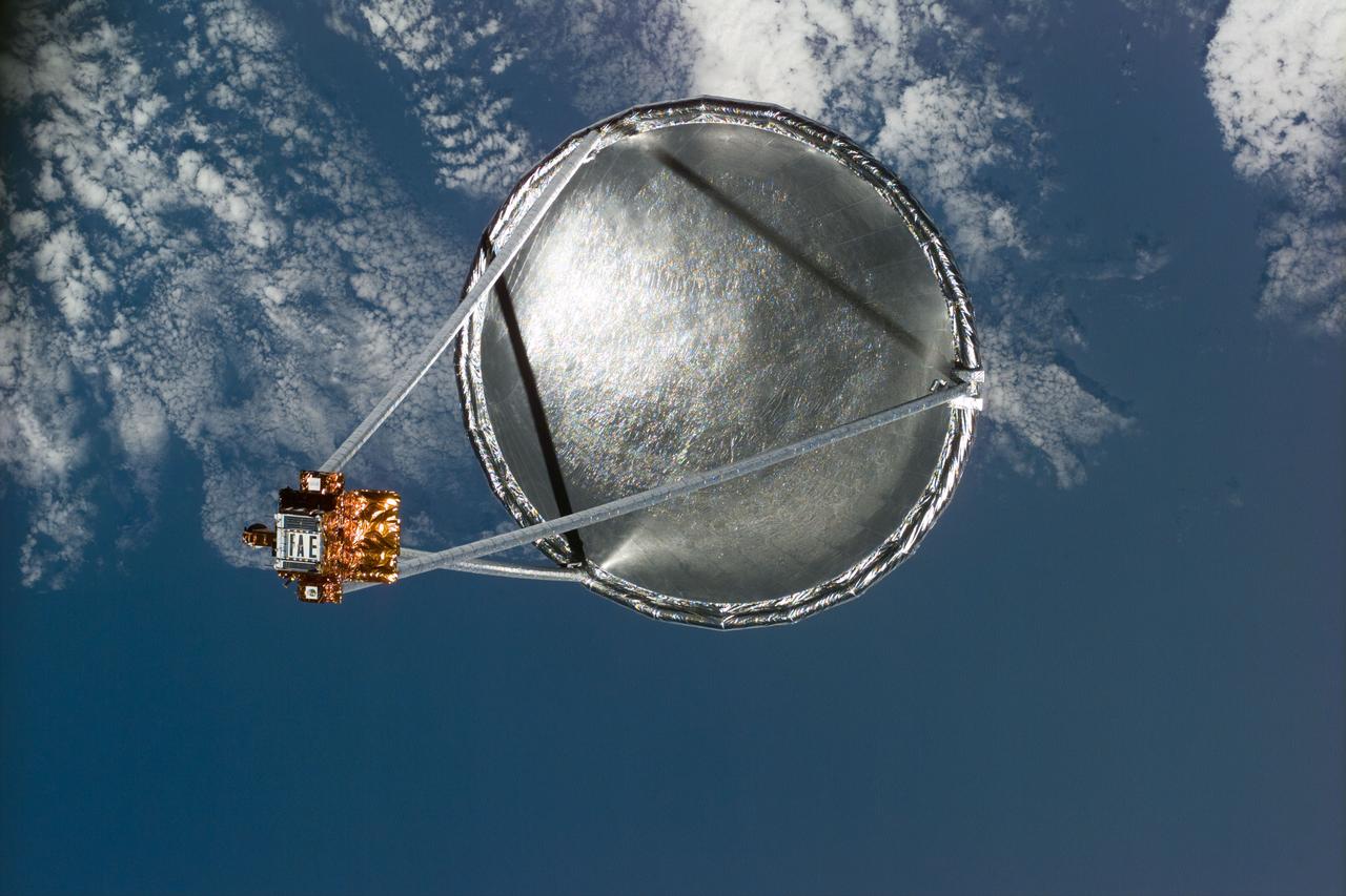
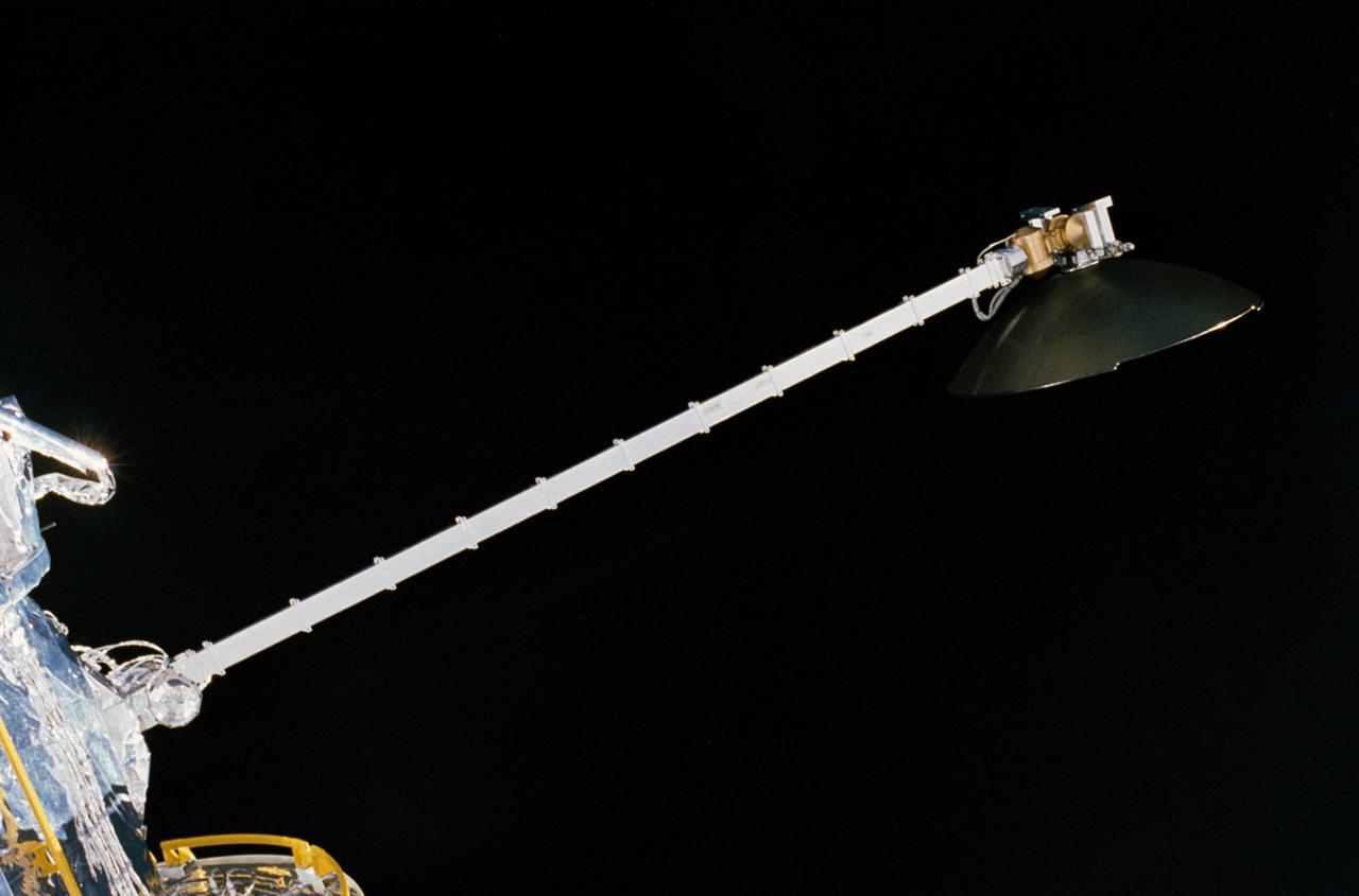
S77-E-5022 (20 May 1996)--- Following its deployment from the Space Shuttle Endeavour, the Spartan 207/Inflatable Antenna Experiment (IAE) payload is backdropped over clouds and water. The view was photographed with an Electronic Still Camera (ESC) and downlinked to flight controllers on the first full day of orbital operations by the six-member crew. Managed by Goddard Space Flight Center (GSFC), Spartan is designed to provide short-duration, free-flight opportunities for a variety of scientific studies. The Spartan configuration on this flight is unique in that the IAE is part of an additional separate unit which is ejected once the experiment is completed. The IAE experiment will lay the groundwork for future technology development in inflatable space structures, which will be launched and then inflated like a balloon on-orbit.
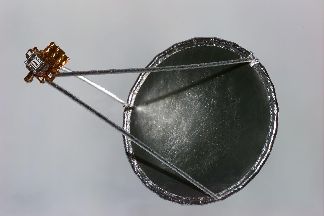
S77-E-5033 (20 May 1996) --- Following its deployment from the Space Shuttle Endeavour, the Spartan 207/Inflatable Antenna Experiment (IAE) payload is backdropped against a wall of grayish clouds. The view was photographed with an Electronic Still Camera (ESC) and downlinked to flight controllers on the first full day of orbital operations by the six-member crew. Managed by Goddard Space Flight Center (GSFC), Spartan is designed to provide short-duration, free-flight opportunities for a variety of scientific studies. The Spartan configuration on this flight is unique in that the IAE is part of an additional separate unit which is ejected once the experiment is completed. The IAE experiment will lay the groundwork for future technology development in inflatable space structures, which will be launched and then inflated like a balloon on-orbit.
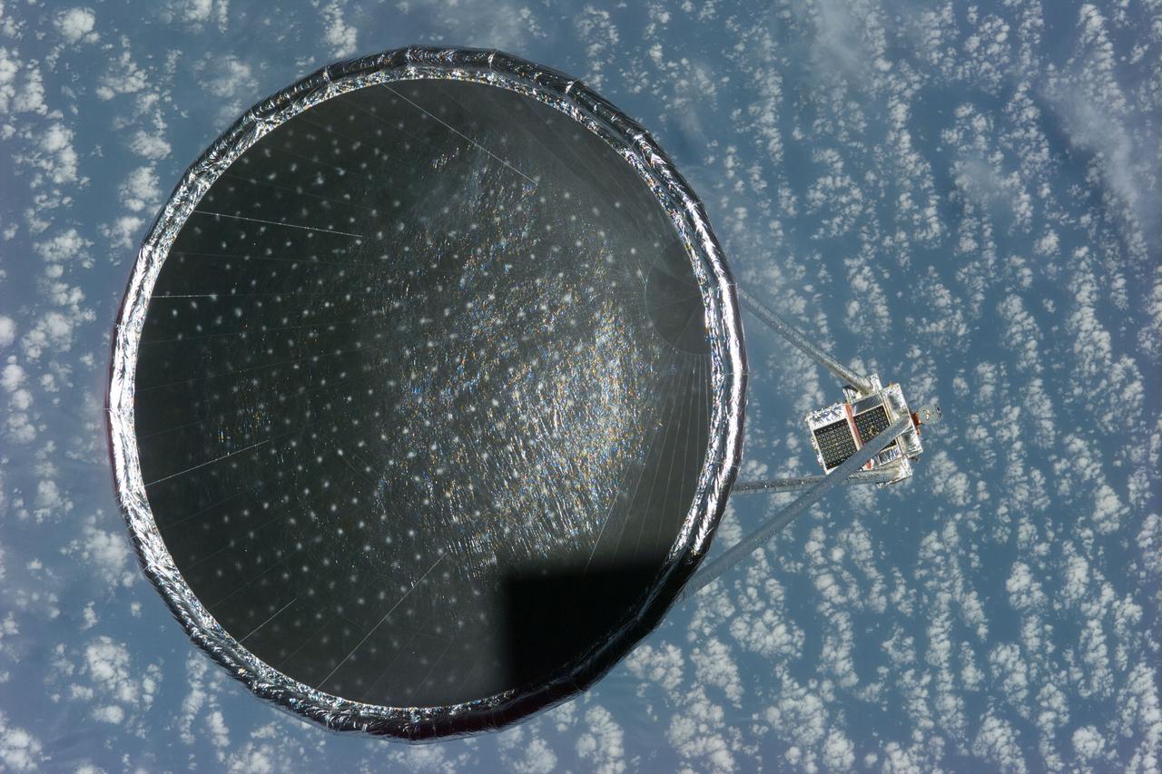
S77-E-5027 (20 May 1996)--- Following its deployment from the Space Shuttle Endeavour, the Spartan 207/Inflatable Antenna Experiment (IAE) payload is backdropped over clouds and water. The view was photographed with an Electronic Still Camera (ESC) and downlinked to flight controllers on the first full day of orbital operations by the six-member crew. Managed by Goddard Space Flight Center (GSFC), Spartan is designed to provide short-duration, free-flight opportunities for a variety of scientific studies. The Spartan configuration on this flight is unique in that the IAE is part of an additional separate unit which is ejected once the experiment is completed. The IAE experiment will lay the groundwork for future technology development in inflatable space structures, which will be launched and then inflated like a balloon on-orbit.
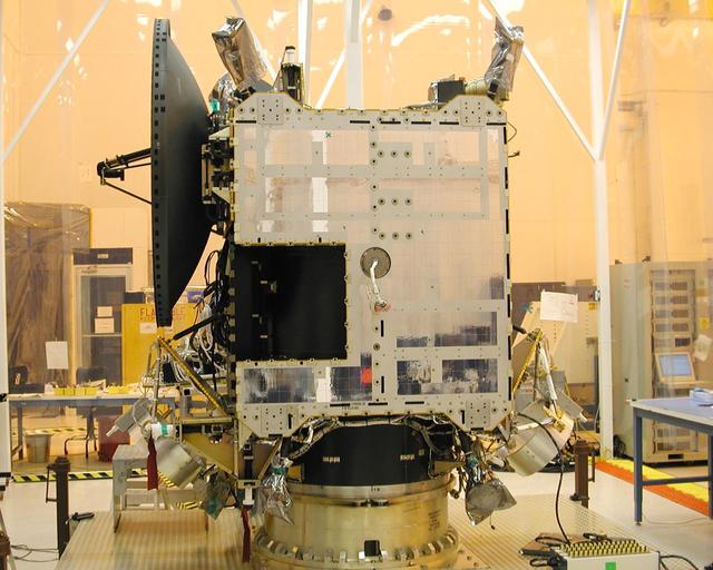
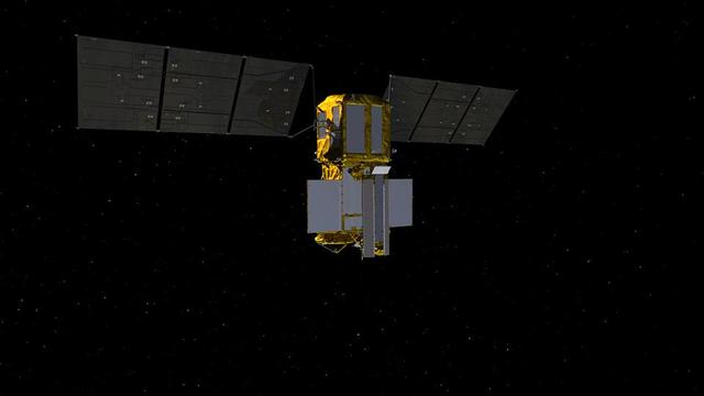
NASA Dawn spacecraft after installation of high gain antenna.
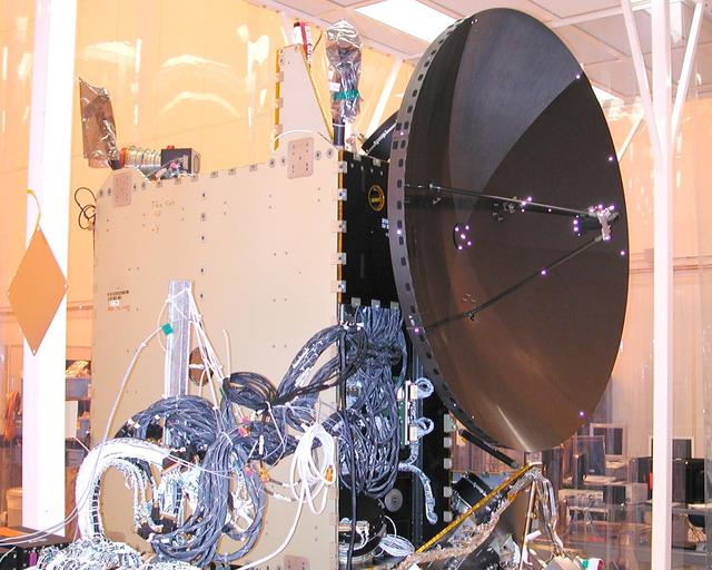
NASA Dawn spacecraft after installation of high gain antenna.
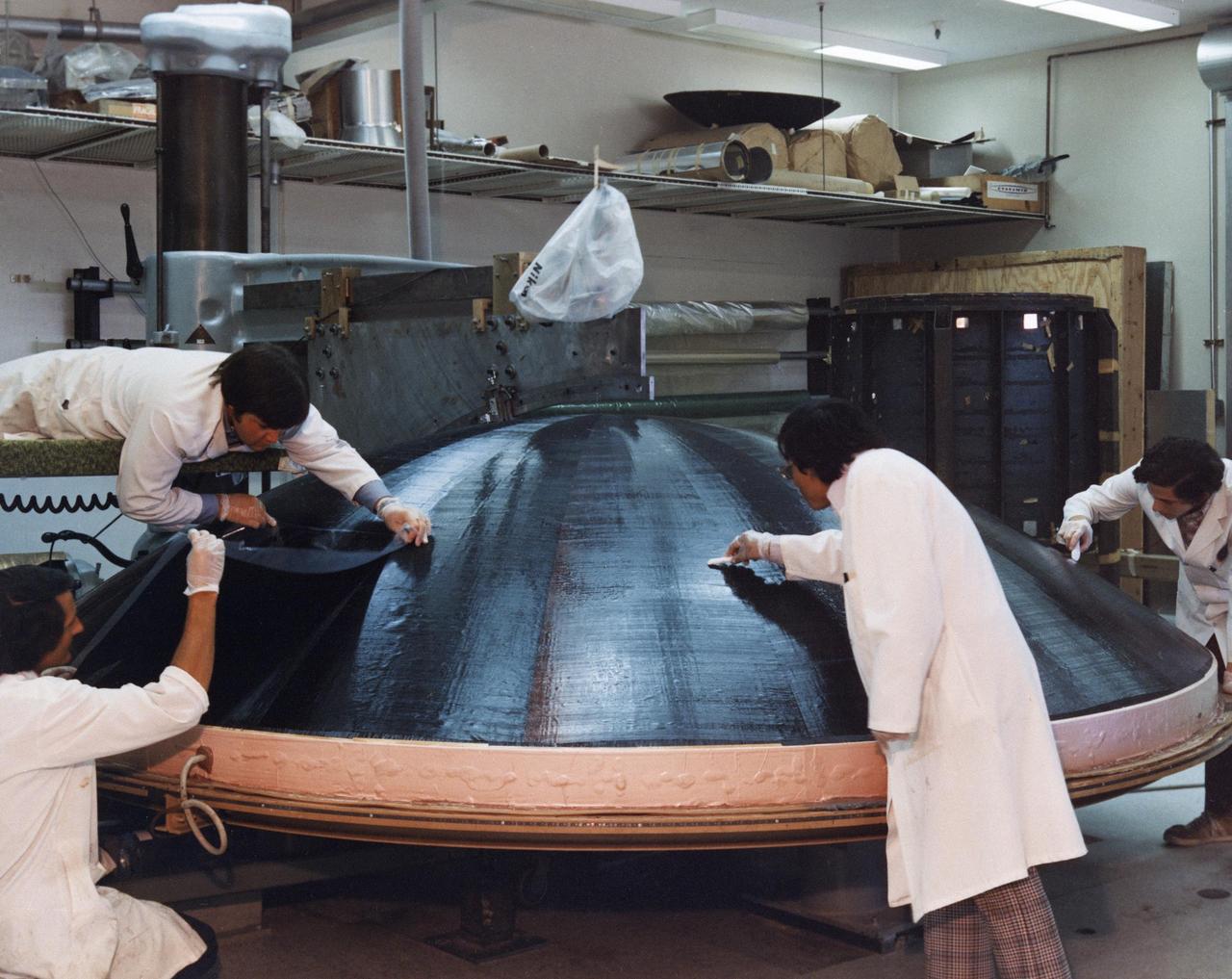
Engineers are engaged in the construction of a high gain antenna for one of the Voyager spacecraft in This archival photo taken on October 29, 1975. https://photojournal.jpl.nasa.gov/catalog/PIA21479
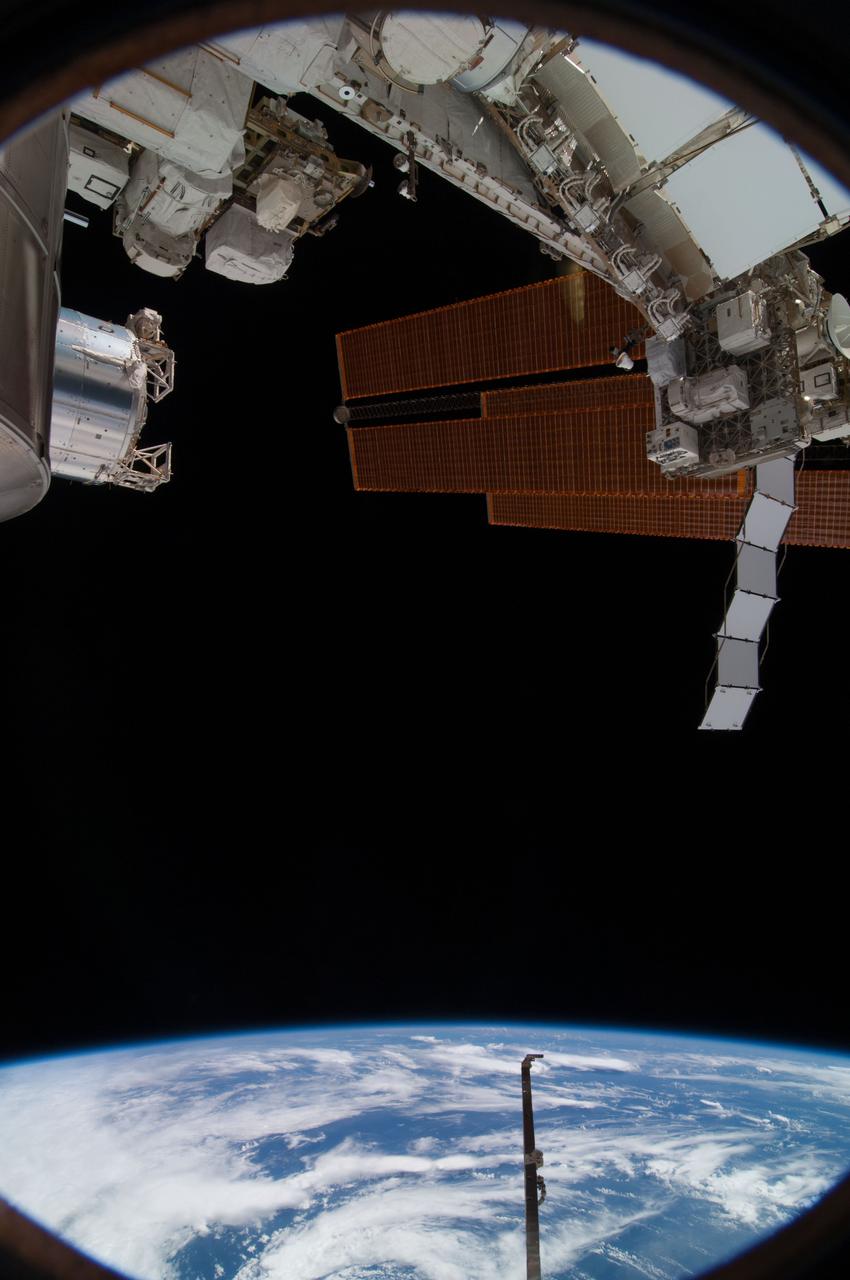
View of antenna and solar arrays (with an Earth limb in the background) taken from a window in the Russian Soyuz spacecraft currently docked to the International Space Station. Photo taken by an Expedition 36 crewmember. Per Twitter message: View out the window to the right of my seat in Soyuz while docked to ISS.
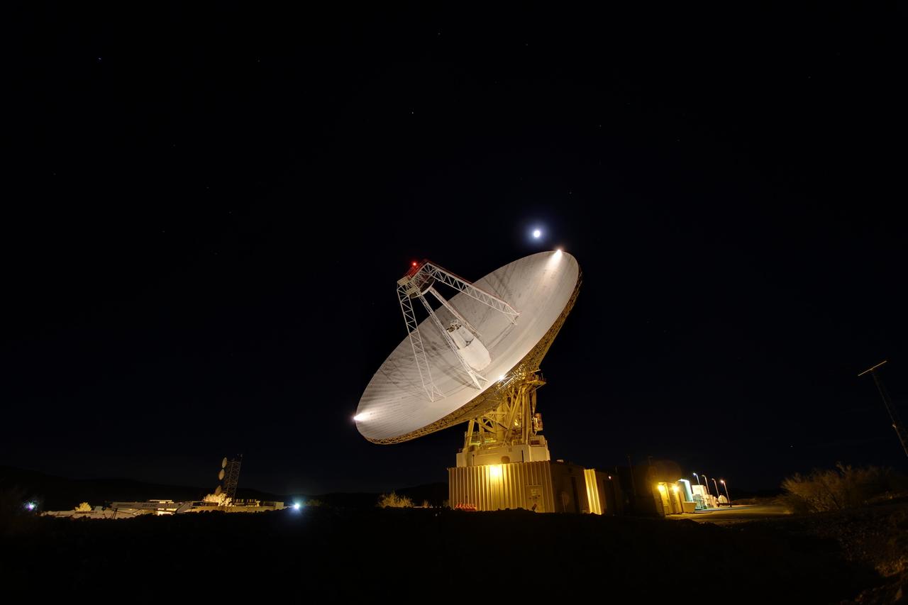
Goldstone 230-foot 70-m antenna tracks under a full moon. The Goldstone Deep Space Communications Complex is located in the Mojave Desert in California, USA.

DSS43 is a 70-meter-wide (230-feet-wide) radio antenna at the Deep Space Network's Canberra facility in Australia. It is the only antenna that can send commands to the Voyager 2 spacecraft. https://photojournal.jpl.nasa.gov/catalog/PIA23682

The NASA/ESA Hubble Space Telescope has snapped the best ever image of the Antennae Galaxies. Hubble has released images of these stunning galaxies twice before, once using observations from its Wide Field and Planetary Camera 2 (WFPC2) in 1997, and again in 2006 from the Advanced Camera for Surveys (ACS). Each of Hubble’s images of the Antennae Galaxies has been better than the last, due to upgrades made during the famous servicing missions, the last of which took place in 2009. The galaxies — also known as NGC 4038 and NGC 4039 — are locked in a deadly embrace. Once normal, sedate spiral galaxies like the Milky Way, the pair have spent the past few hundred million years sparring with one another. This clash is so violent that stars have been ripped from their host galaxies to form a streaming arc between the two. In wide-field images of the pair the reason for their name becomes clear — far-flung stars and streamers of gas stretch out into space, creating long tidal tails reminiscent of antennae. This new image of the Antennae Galaxies shows obvious signs of chaos. Clouds of gas are seen in bright pink and red, surrounding the bright flashes of blue star-forming regions — some of which are partially obscured by dark patches of dust. The rate of star formation is so high that the Antennae Galaxies are said to be in a state of starburst, a period in which all of the gas within the galaxies is being used to form stars. This cannot last forever and neither can the separate galaxies; eventually the nuclei will coalesce, and the galaxies will begin their retirement together as one large elliptical galaxy. This image uses visible and near-infrared observations from Hubble’s Wide Field Camera 3 (WFC3), along with some of the previously-released observations from Hubble’s Advanced Camera for Surveys (ACS). Credit: NASA/European Space Agency <b><a href="http://www.nasa.gov/audience/formedia/features/MP_Photo_Guidelines.html" rel="nofollow">NASA image use policy.</a></b> <b><a href="http://www.nasa.gov/centers/goddard/home/index.html" rel="nofollow">NASA Goddard Space Flight Center</a></b> enables NASA’s mission through four scientific endeavors: Earth Science, Heliophysics, Solar System Exploration, and Astrophysics. Goddard plays a leading role in NASA’s accomplishments by contributing compelling scientific knowledge to advance the Agency’s mission. <b>Follow us on <a href="http://twitter.com/NASA_GoddardPix" rel="nofollow">Twitter</a></b> <b>Like us on <a href="http://www.facebook.com/pages/Greenbelt-MD/NASA-Goddard/395013845897?ref=tsd" rel="nofollow">Facebook</a></b> <b>Find us on <a href="http://instagram.com/nasagoddard?vm=grid" rel="nofollow">Instagram</a></b>
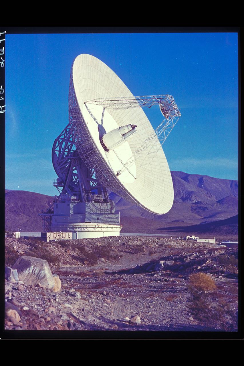
Deep Space Antenna 210' at Goldstone, CA (JPL ref: P-116594AC)
Held in appendage deploy position, the Hubble Space Telescope's (HST's) high gain antenna (HGA) has been released from its stowed position along the Support System Module (SSM) forward shell. The STS-31 crew aboard Discovery, Orbiter Vehicle (OV) oversees the automatic HGA deployment prior to releasing HST. HST HGA is backdropped against the blackness of space.
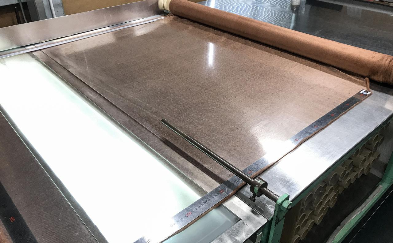
jsc2020e040944 (7/8/2020) --- Copper zirconium antenna metal mesh. The Exposure Experiment of Copper-Zirconium Antenna Metal Mesh to the Space Environment (ExHAM-Antenna Metal Mesh) investigation tests how well an antenna metal mesh, made from copper and zirconium, performs in the space environment in low-Earth orbit (LEO). While in space, the antenna metal mesh is exposed to cosmic rays and atomic oxygen in the LEO space environment - which can degrade antenna performance. Image Credit: NGK Insulators, Ltd., Taiyo Wire Cloth Co., Ltd., Technosolver Corporation, Koyo Materica Corporation, JAXA..
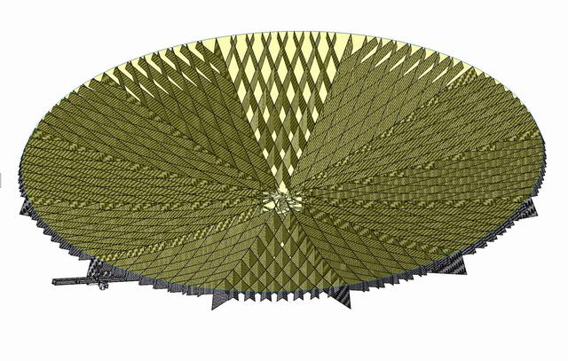
jsc2020e040943 (9/10/2020) --- An example of a copper zirconium antenna metal mesh on a deployable reflector. The Exposure Experiment of Copper-Zirconium Antenna Metal Mesh to the Space Environment (ExHAM-Antenna Metal Mesh) investigation tests how well an antenna metal mesh, made from copper and zirconium, performs in the space environment in low-Earth orbit (LEO). While in space, the antenna metal mesh is exposed to cosmic rays and atomic oxygen in the LEO space environment - which can degrade antenna performance. Image Credit: Technosolver Corporation, JAXA.

jsc2020e040945 (7/10/2020) --- Copper zirconium antenna metal mesh. The Exposure Experiment of Copper-Zirconium Antenna Metal Mesh to the Space Environment (ExHAM-Antenna Metal Mesh) investigation tests how well an antenna metal mesh, made from copper and zirconium, performs in the space environment in low-Earth orbit (LEO). While in space, the antenna metal mesh is exposed to cosmic rays and atomic oxygen in the LEO space environment - which can degrade antenna performance. Image Credit: NGK Insulators, Ltd., Taiyo Wire Cloth Co., Ltd., Technosolver Corporation, Koyo Materica Corporation, JAXA..
This video animation shows antennas for the Ka-band Radar Interferometer (KaRIn) instrument deploying on the Surface Water and Ocean Topography (SWOT) satellite. KaRIn is the scientific heart of the spacecraft, which launched into Earth orbit on Friday, Dec. 16, 2022, from Vandenberg Space Force Base in central California. SWOT will measure the height of water on over 90% of Earth's surface, providing a high-definition survey of our planet's water for the first time. But before it can do that, engineers need to deploy the satellite's solar panel arrays, which power the spacecraft, and unfold the large mast and antenna panels for the KaRIn instrument. The mast and antenna deployment is a four-day process. Thirty-three feet (10 meters) apart, at either end of the mast, the two antennas are designed to capture precise measurements of the height of water in Earth's freshwater bodies and the ocean. KaRIn will see eddies, currents, and other ocean features less than 13 miles (20 kilometers) across, and it will collect data on lakes and reservoirs larger than 15 acres (62,500 square meters) and rivers wider than 330 feet (100 meters) across. KaRIn will do this by bouncing radar pulses off the surface of the water and receiving the return signals with both of those antennas, collecting data along a swath on the surface that's 30 miles (50 kilometers) wide on either side of the satellite. The data SWOT provides will help researchers and decision-makers address some of the most pressing climate questions of our time and help communities prepare for a warming world. Animation available at https://photojournal.jpl.nasa.gov/catalog/PIA25596
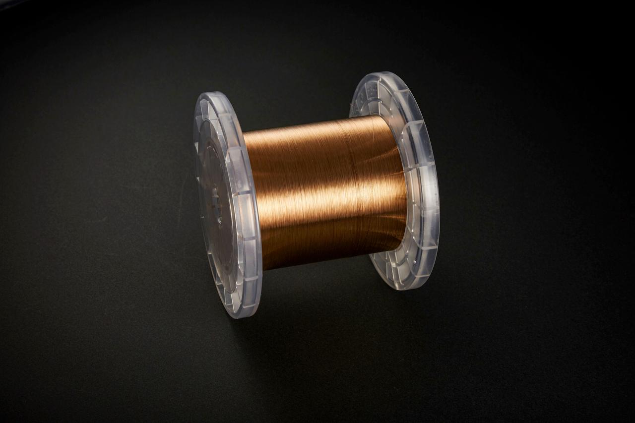
jsc2020e040942 (4/18/2015) --- Copper zirconium alloy wire. The Exposure Experiment of Copper-Zirconium Antenna Metal Mesh to the Space Environment (ExHAM-Antenna Metal Mesh) investigation tests how well an antenna metal mesh, made from copper and zirconium, performs in the space environment in low-Earth orbit (LEO). While in space, the antenna metal mesh is exposed to cosmic rays and atomic oxygen in the LEO space environment - which can degrade antenna performance. Image Credit: NGK Insulators, Ltd., Taiyo Wire Cloth Co., Ltd., Technosolver Corporation, Koyo Materica Corporation, JAXA..
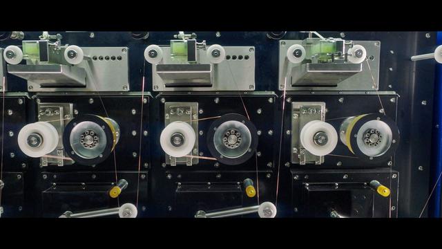
jsc2020e040941 (9/3/2018) --- Copper zirconium alloy wire being produced. The Exposure Experiment of Copper-Zirconium Antenna Metal Mesh to the Space Environment (ExHAM-Antenna Metal Mesh) investigation tests how well an antenna metal mesh, made from copper and zirconium, performs in the space environment in low-Earth orbit (LEO). While in space, the antenna metal mesh is exposed to cosmic rays and atomic oxygen in the LEO space environment - which can degrade antenna performance. Image Credit: NGK Insulators, Ltd., Taiyo Wire Cloth Co., Ltd., Technosolver Corporation, Koyo Materica Corporation, JAXA..
jsc2020e040940 (9/3/2018) --- Copper zirconium alloy wire being produced. The Exposure Experiment of Copper-Zirconium Antenna Metal Mesh to the Space Environment (ExHAM-Antenna Metal Mesh) investigation tests how well an antenna metal mesh, made from copper and zirconium, performs in the space environment in low-Earth orbit (LEO). While in space, the antenna metal mesh is exposed to cosmic rays and atomic oxygen in the LEO space environment - which can degrade antenna performance. Image Credit: NGK Insulators, Ltd., Taiyo Wire Cloth Co., Ltd., Technosolver Corporation, Koyo Materica Corporation, JAXA..
On May 3, 2010, workers at NASA Deep Space Network Goldstone Deep Space Communications Complex removed one of the large steel pads that help the giant Mars antenna rotate sideways.
Workers at NASA Deep Space Network Goldstone Deep Space Communications Complex put into place a set of support legs to help hold up a portion of the giant Mars antenna on May 4, 2010.
A worker at NASA Deep Space Network Goldstone Deep Space Communications Complex radios to his colleagues that 12 jacks are ready to lift the upper section of the giant Mars antenna.
Workers in Goldstone, Calif., guide a new runner segment into the hydrostatic bearing assembly of a giant, 70-meter-wide 230-foot-wide antenna that is a critical part of NASA Deep Space Network.
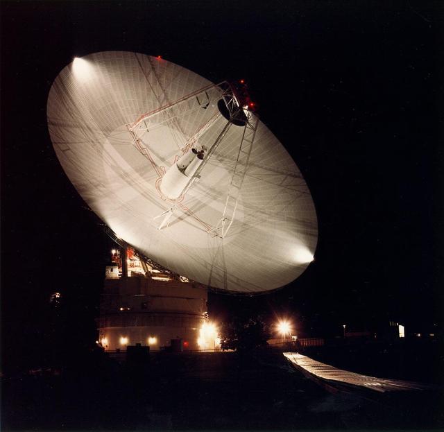
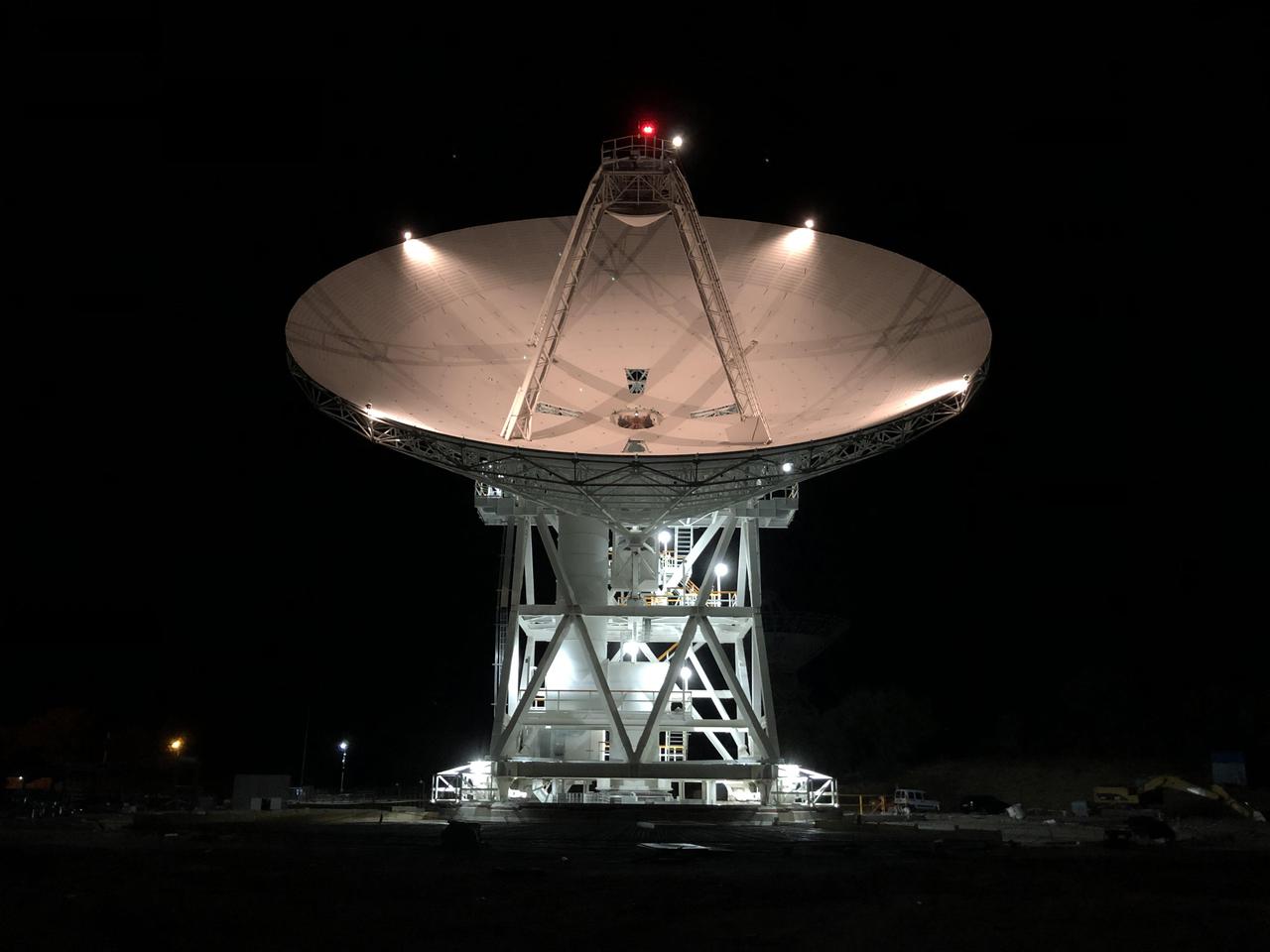
Night shot of the 70m antenna at Goldstone, California. The parabolic dish is 70m 230 ft. in diameter. The Goldstone Deep Space Communications Complex, located in the Mojave Desert in California, is one of three complexes which comprise NASA DSN.
The GPM High Gain Antenna System (HGAS) in integration and testing at Goddard Space Flight Center. Credit: Craig E. Huber, Chief Engineer SGT Inc, NASA Goddard Space Flight Center The Global Precipitation Measurement (GPM) mission is an international partnership co-led by NASA and the Japan Aerospace Exploration Agency (JAXA) that will provide next-generation global observations of precipitation from space. GPM will study global rain, snow and ice to better understand our climate, weather, and hydrometeorological processes. As of Novermber 2013 the GPM Core Observatory is in the final stages of testing at NASA Goddard Space Flight Center. The satellite will be flown to Japan in the fall of 2013 and launched into orbit on an HII-A rocket in early 2014. For more on the GPM mission, visit <a href="http://gpm.gsfc.nasa.gov/" rel="nofollow">gpm.gsfc.nasa.gov/</a>. <b><a href="http://www.nasa.gov/audience/formedia/features/MP_Photo_Guidelines.html" rel="nofollow">NASA image use policy.</a></b> <b><a href="http://www.nasa.gov/centers/goddard/home/index.html" rel="nofollow">NASA Goddard Space Flight Center</a></b> enables NASA’s mission through four scientific endeavors: Earth Science, Heliophysics, Solar System Exploration, and Astrophysics. Goddard plays a leading role in NASA’s accomplishments by contributing compelling scientific knowledge to advance the Agency’s mission. <b>Follow us on <a href="http://twitter.com/NASA_GoddardPix" rel="nofollow">Twitter</a></b> <b>Like us on <a href="http://www.facebook.com/pages/Greenbelt-MD/NASA-Goddard/395013845897?ref=tsd" rel="nofollow">Facebook</a></b> <b>Find us on <a href="http://instagram.com/nasagoddard?vm=grid" rel="nofollow">Instagram</a></b>
The massive high-gain antenna for NASA's Europa Clipper mission is complete. The antenna is nearly 10 feet (3 meters) wide and will be integrated along with other telecommunications hardware into the spacecraft's propulsion module. The antenna will download science data and allow ground controllers to send and receive commands and data between Earth and the spacecraft in Jupiter orbit – more than a million times farther from Earth than the International Space Station's orbits. It was designed by the Johns Hopkins Applied Physics Laboratory (APL) in Laurel, Maryland, and aerospace vendor Applied Aerospace Structures Corporation (AASC) in Stockton, California. With an internal global ocean under a thick layer of ice, Jupiter's moon Europa may have the potential to harbor existing life. Europa Clipper will swoop around Jupiter in an elliptical orbit, dipping close to the moon on each flyby to collect data. Understanding Europa's habitability will help scientists better understand how life developed on Earth and the potential for finding life beyond our planet. Europa Clipper is set to launch in 2024. https://photojournal.jpl.nasa.gov/catalog/PIA24899
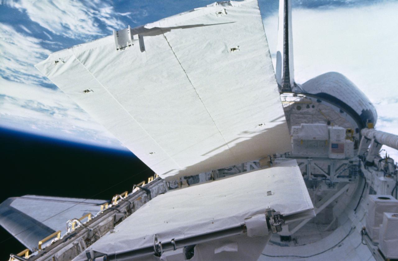
View of the SIR-B antenna being deployed during STS 41-G. The Challenger's payload bay is open and the remote manipulator system (RMS) arm is in the stowed position at the right of the view.
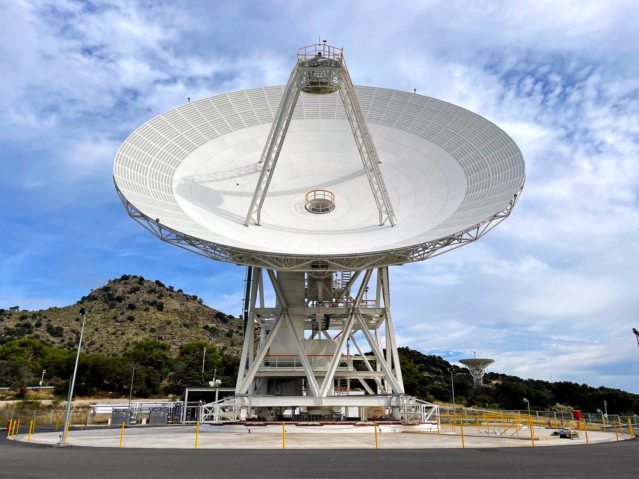
Deep Space Station 53, or DSS-53, is a new 34-meter (111-foot) beam waveguide antenna that went online in February 2022 at NASA's Deep Space Network's ground station in Madrid. DSS-53 is the fourth of six antennas being added to expand the DSN's capacity and meet the needs of a growing number of spacecraft. When the project is complete, each of the network's three ground stations around the globe will have four beam waveguide antennas. The Madrid Deep Space Communications Complex is the first to have completed its build-out as part of project. Construction on DSS-53 began in 2016. https://photojournal.jpl.nasa.gov/catalog/PIA25136
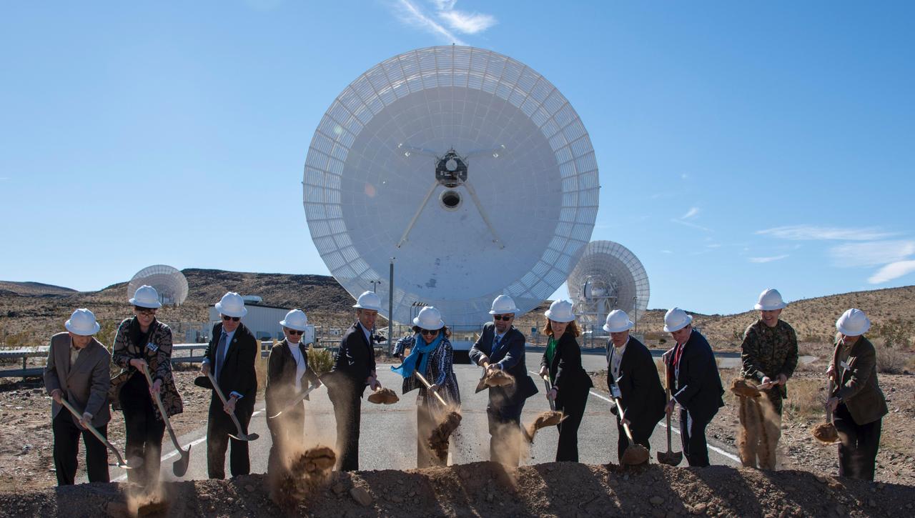
On Feb. 11, 2020, NASA, JPL, military and local officials broke ground in Goldstone, California, for a new antenna in the agency's Deep Space Network, which communicates with all its deep space missions. When completed in 2 ½ years, the new 112-foot-wide (34-meter-wide) antenna dish will include mirrors and a special receiver for optical, or laser, communications from deep space missions. https://photojournal.jpl.nasa.gov/catalog/PIA23618
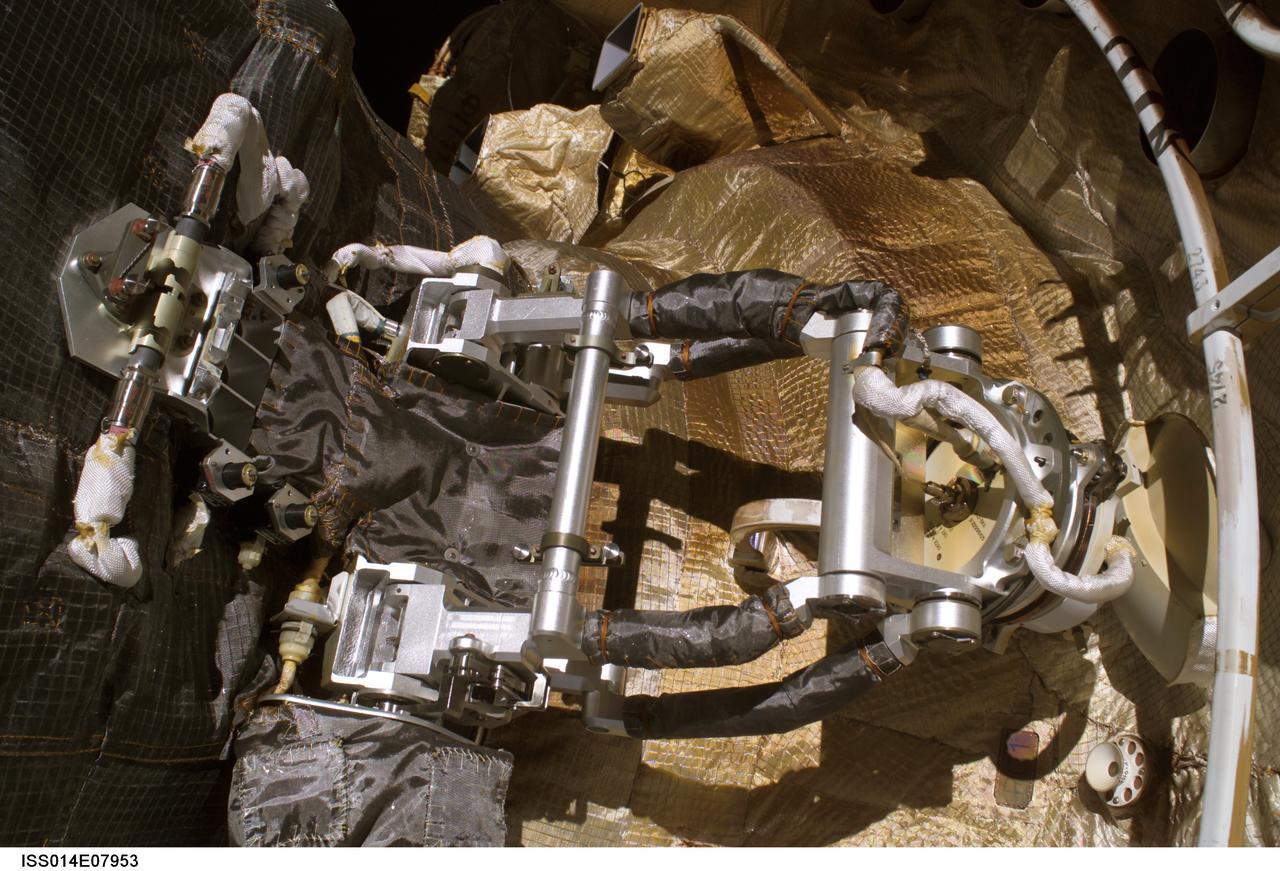
ISS014-E-07953 (22 Nov. 2006) ---This photo shows the position of the KURS antennae on 23 Progress as seen by spacewalkers Michael Lopez-Alegria and Mikhail Tyurin during Russian EVA 17 on Nov. 22. During docking of the Progress to the International Space Station on Oct. 26, 2006, flight controllers were unable to confirm if the antenna had retracted as commanded. On the right-hand side of the photo, there is a visible clearance between the antennae's satellite dish and handrail 2745 on the ISS Service Module.

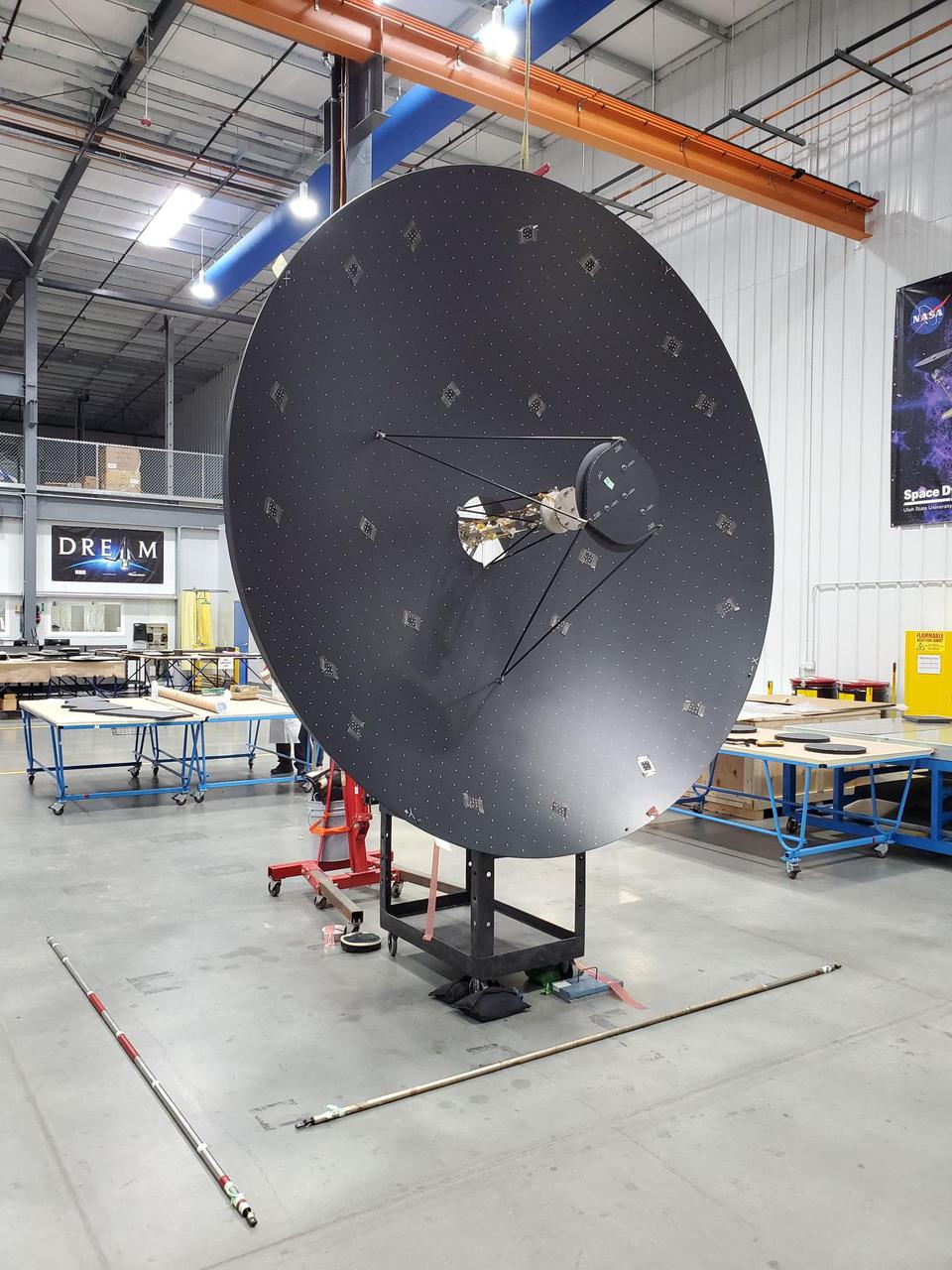
A full-scale prototype of the high-gain antenna on NASA's Europa Clipper spacecraft is undergoing testing in the Experimental Test Range at NASA's Langley Research Center in Hampton, Virginia. The Europa Clipper is expected to launch on a mission to conduct detailed reconnaissance of Jupiter's moon Europa in the 2020s. https://photojournal.jpl.nasa.gov/catalog/PIA22773
Deep Space Station 56, or DSS-56, is a powerful 34-meter-wide (112-foot-wide) antenna that was added to the Deep Space Network's Madrid Deep Space Communications Complex in Spain in early 2021 after beginning construction in 2017. Deep Space Network (DSN) radio antennas communicate with spacecraft throughout the solar system. Previous antennas have been limited in the frequency bands they can receive and transmit, often being restricted to communicating only with specific spacecraft. DSS-56 is the first to use the DSN's full range of communication frequencies. This means DSS-56 is an "all-in-one" antenna that can communicate with all the missions that the DSN supports and can be used as a backup for any of the Madrid complex's other antennas. With the addition of DSS-56 and other 34-meter antennas to all three DSN complexes, the network is preparing to play a critical role in ensuring communication and navigation support for upcoming Moon and Mars missions and the crewed Artemis missions. https://photojournal.jpl.nasa.gov/catalog/PIA24163
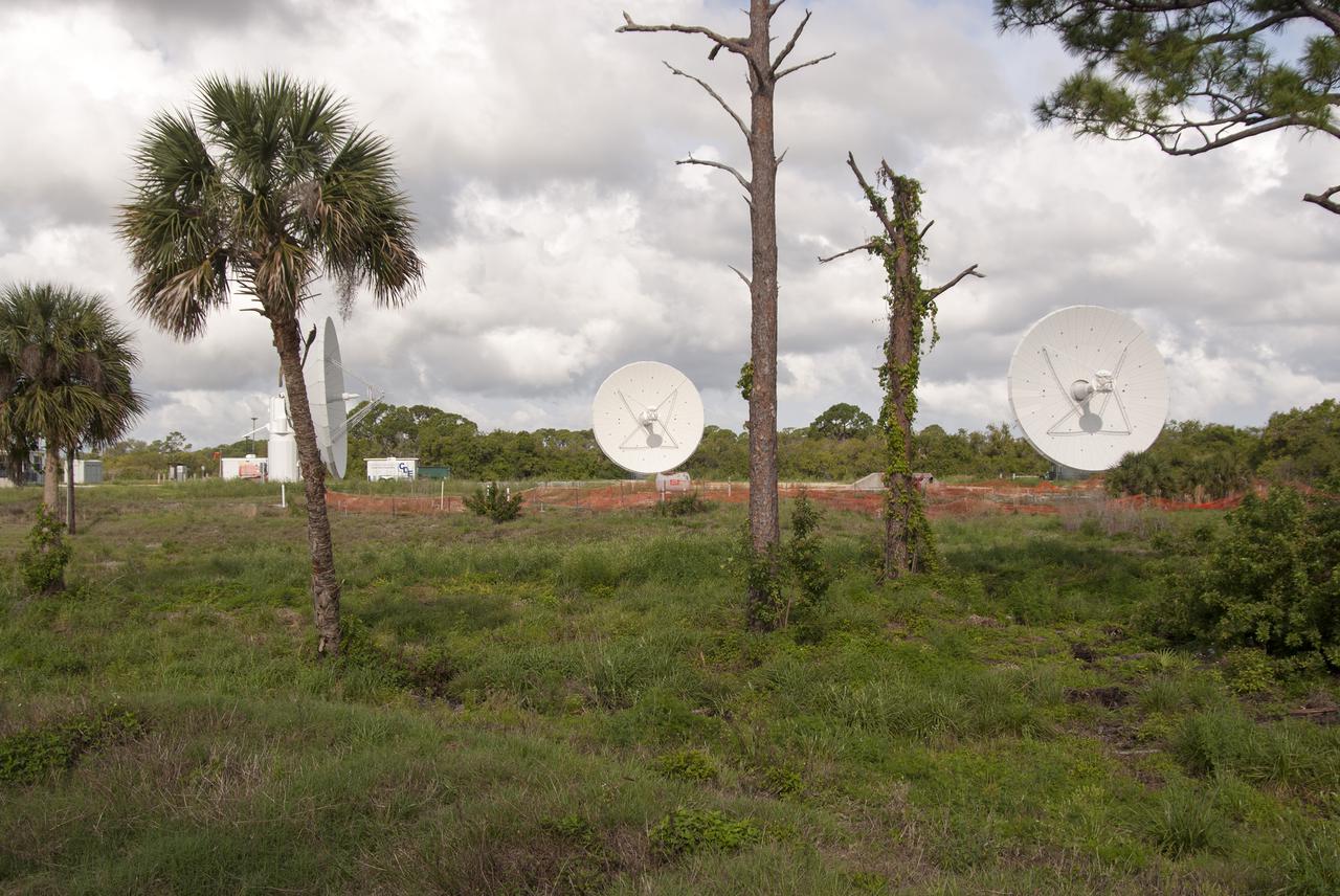
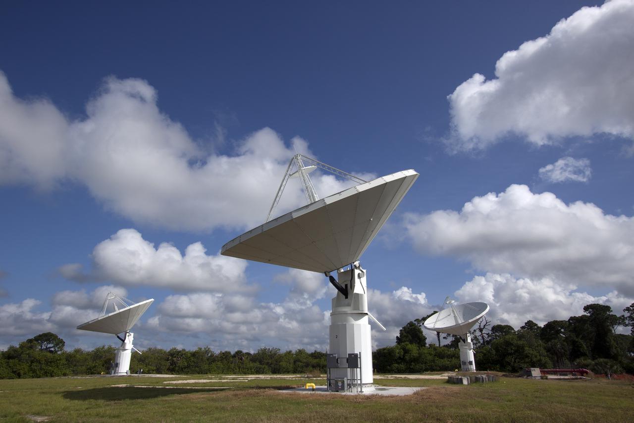
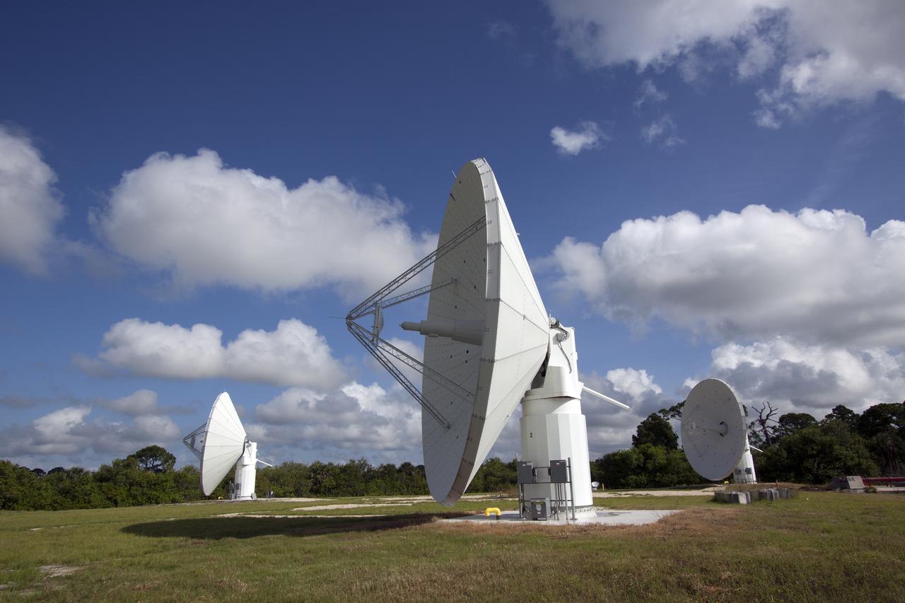
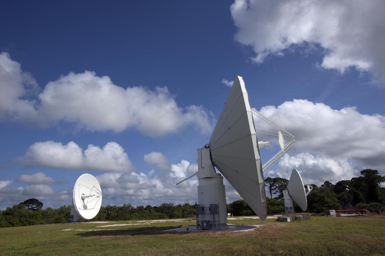
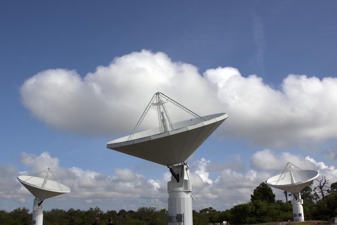
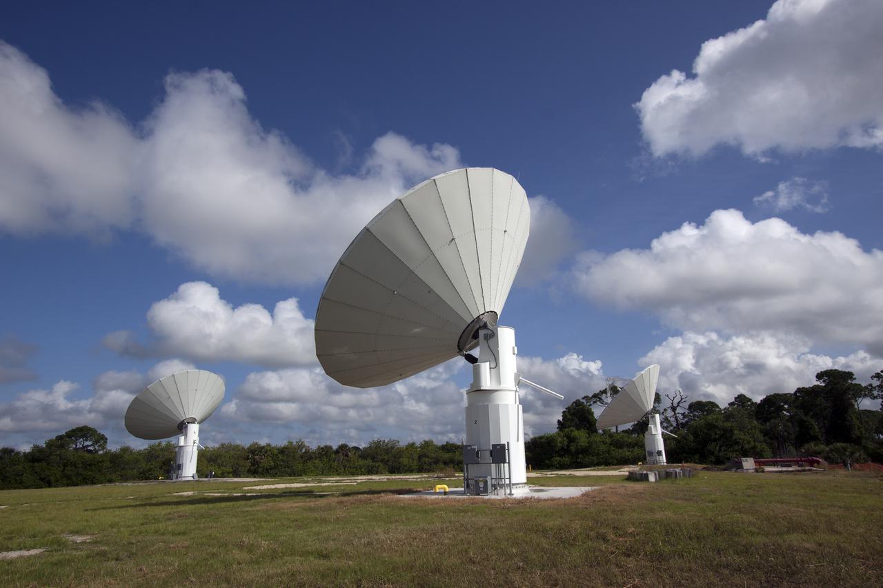
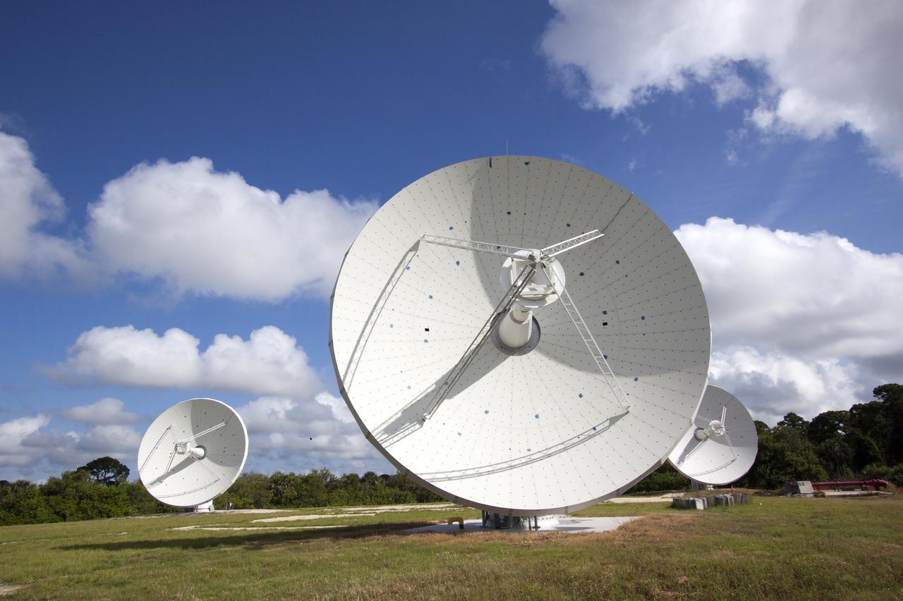
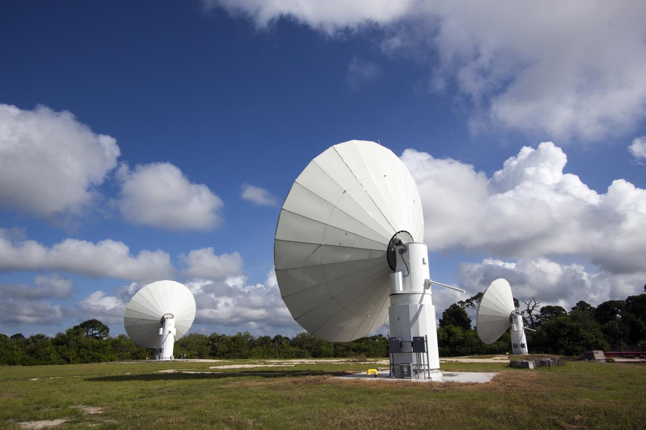
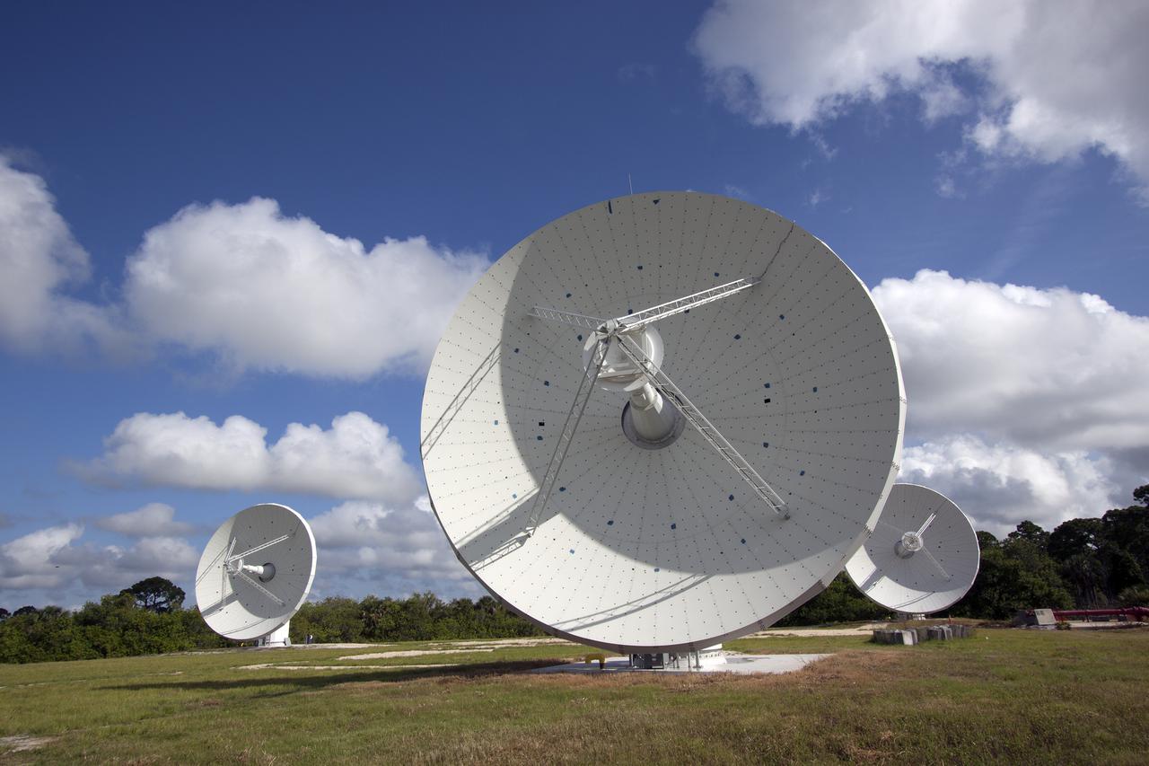
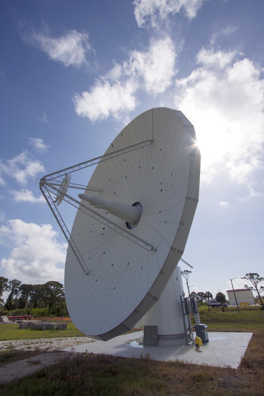
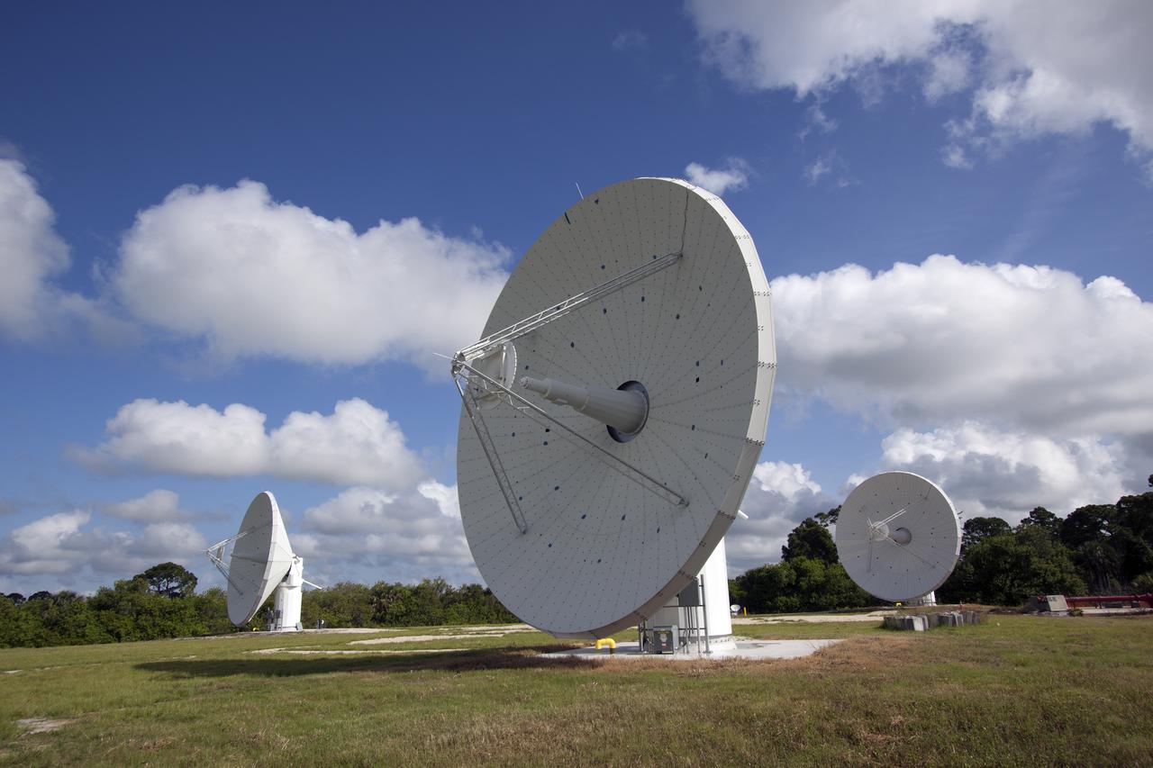
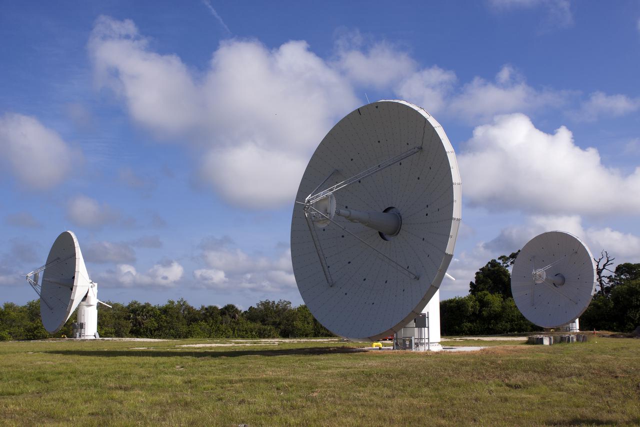
CAPE CANAVERAL, Fla. – At NASA’s Kennedy Space Center in Florida, construction is almost complete on the Antenna Test Bed Array for the Ka-Band Objects Observation and Monitoring, or Ka-BOOM, system. The Ka-BOOM project is one of the final steps in developing the techniques to build a high power, high resolution radar system capable of becoming a Near Earth Object Early Warning System. While also capable of space communication and radio science experiments, developing radar applications is the primary focus of the arrays. The 40-foot-diameter dish antenna arrays are near the former Vertical Processing Facility, which has been demolished. Photo credit: NASA_Charisse Nahser
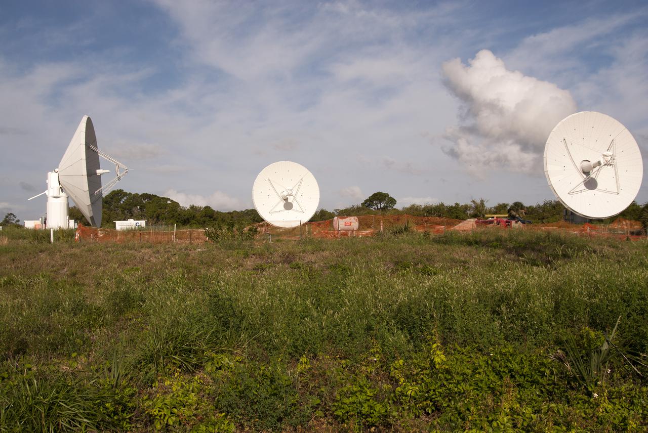
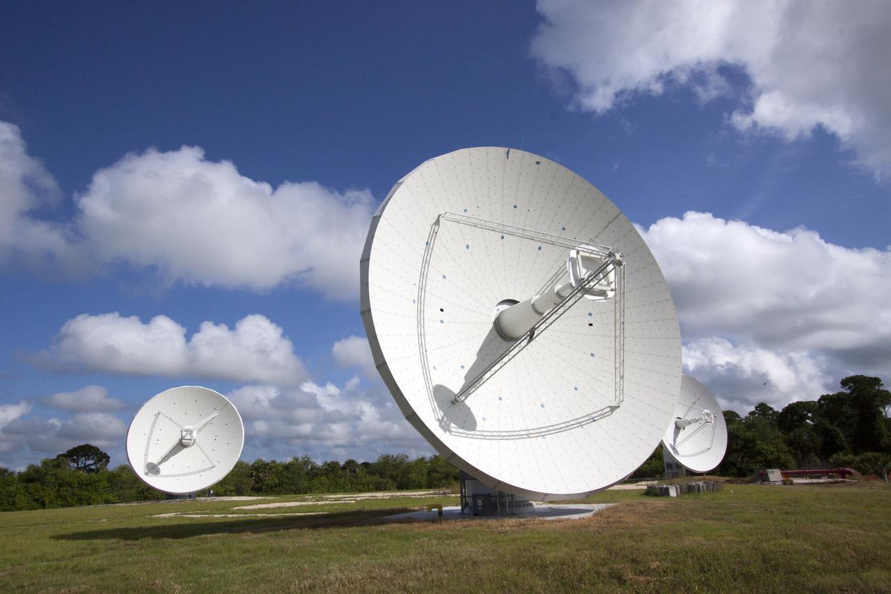
CAPE CANAVERAL, Fla. – At NASA’s Kennedy Space Center in Florida, construction is almost complete on the Antenna Test Bed Array for the Ka-Band Objects Observation and Monitoring, or Ka-BOOM, system. The Ka-BOOM project is one of the final steps in developing the techniques to build a high power, high resolution radar system capable of becoming a Near Earth Object Early Warning System. While also capable of space communication and radio science experiments, developing radar applications is the primary focus of the arrays. The 40-foot-diameter dish antenna arrays are near the former Vertical Processing Facility, which has been demolished. Photo credit: NASA_Charisse Nahser
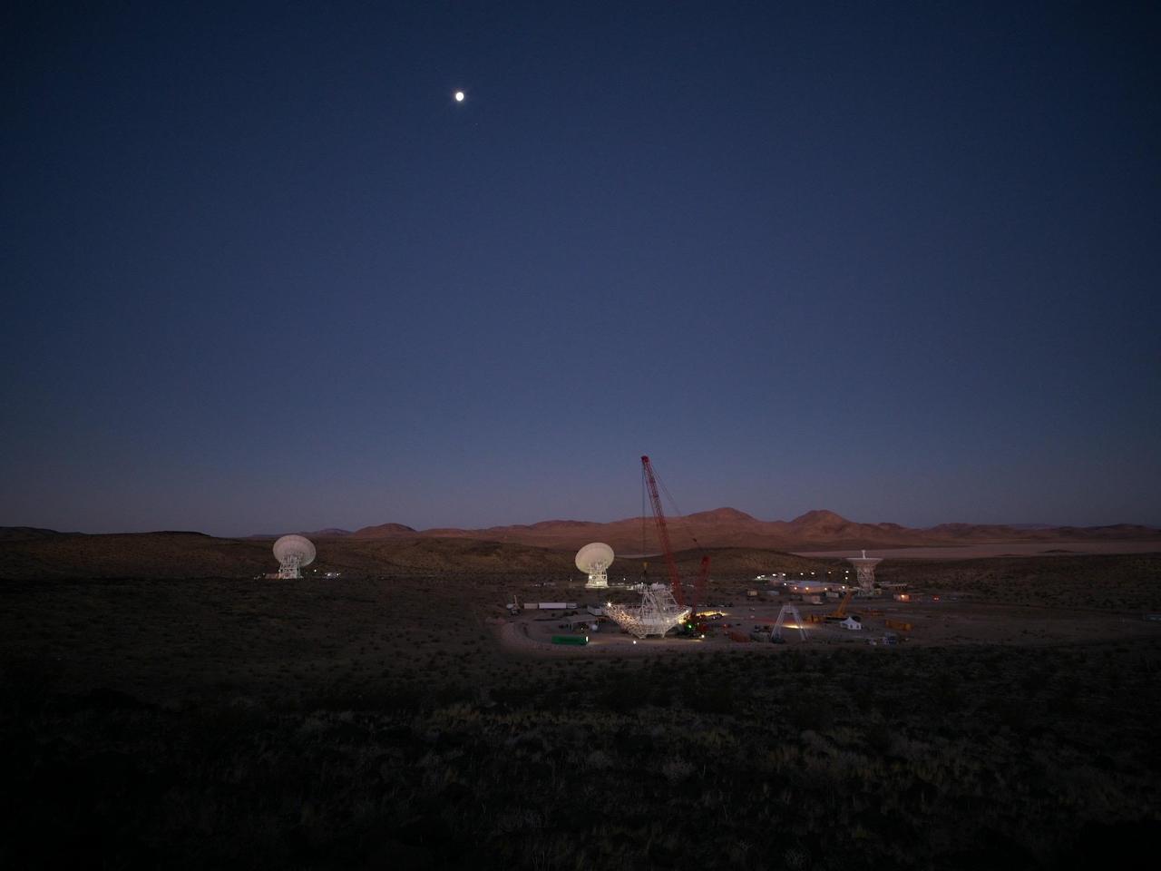
In the early morning of Dec. 18, 2024, a crane looms over the 112-foot-wide (34-meter-wide) steel framework for Deep Space Station 23 (DSS-23) reflector dish, which will soon be lowered into position on the antenna's base structure. Located at the Deep Space Network's Goldstone Space Communications Complex near Barstow, California, DSS-23 is a multi-frequency beam waveguide antenna that will boost the DSN's capacity and enhance NASA's deep space communications capabilities for decades to come. In the background are, from left to right, the beam waveguide antennas DSS-25 and DSS-26, and the decommissioned 85-foot (26-meter) Apollo antenna. https://photojournal.jpl.nasa.gov/catalog/PIA26456
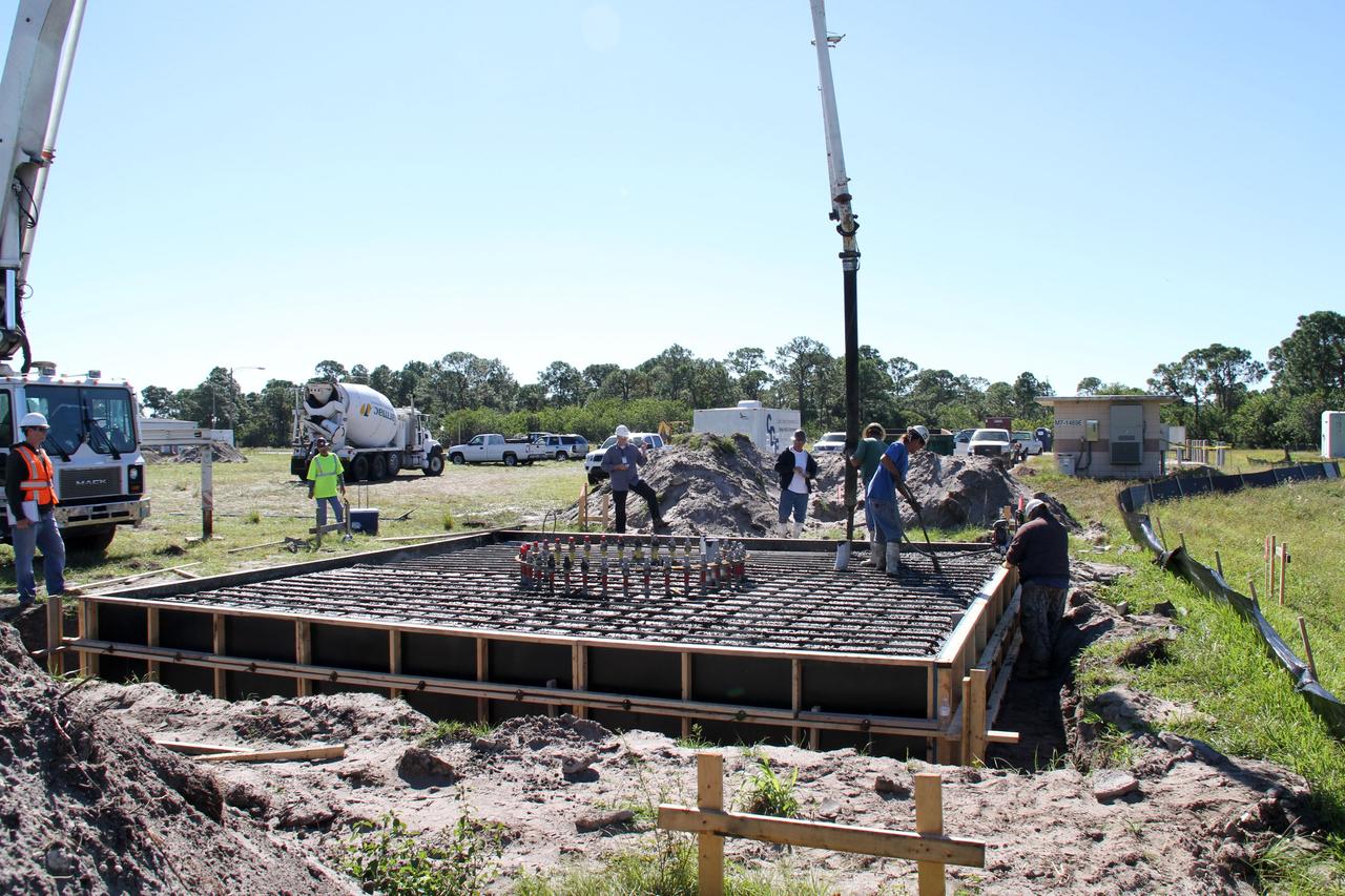
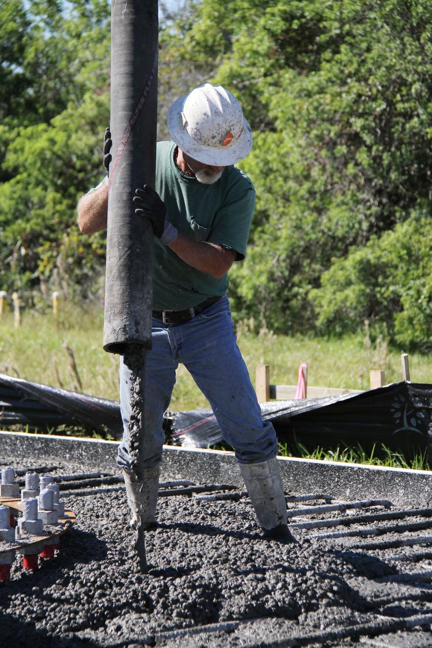
CAPE CANAVERAL, Fla. – At NASA’s Kennedy Space Center in Florida, workers pour concrete at the base of the site of the Antenna Test Bed Array for the Ka-Band Objects Observation and Monitoring, or Ka-BOOM system. The construction site is near the former Vertical Processing Facility, which has been demolished. Workers are placing the pile foundations for the 40-foot-diameter dish antenna arrays and their associated utilities, and preparing the site for the operations command center facility. Photo credit: NASA/Ben Smegelski

CAPE CANAVERAL, Fla. – At NASA’s Kennedy Space Center in Florida, concrete has been poured at the site of the Antenna Test Bed Array for the Ka-Band Objects Observation and Monitoring, Ka-BOOM system. The construction site is near the former Vertical Processing Facility, which has been demolished. Workers are placing the pile foundations for the 40-foot-diameter dish antenna arrays and their associated utilities, and preparing the site for the operations command center facility. Photo credit: NASA/Ben Smegelski
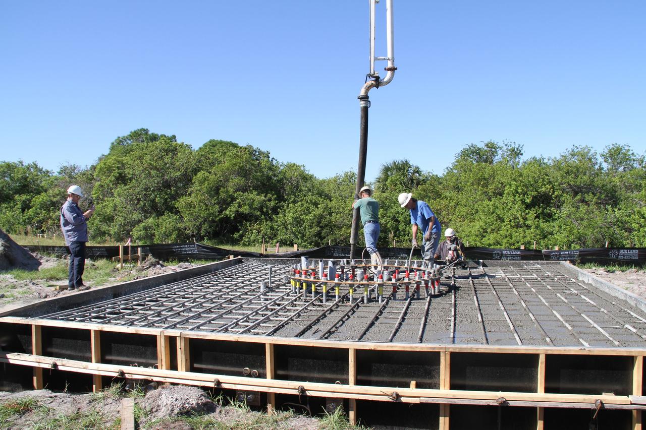
CAPE CANAVERAL, Fla. – At NASA’s Kennedy Space Center in Florida, workers continue construction of the Antenna Test Bed Array for the Ka-Band Objects Observation and Monitoring, or Ka-BOOM, system. The construction site is near the former Vertical Processing Facility, which has been demolished. Workers are placing the pile foundations for the 40-foot-diameter dish antenna arrays and their associated utilities, and preparing the site for the operations command center facility. Photo credit: NASA/Ben Smegelski
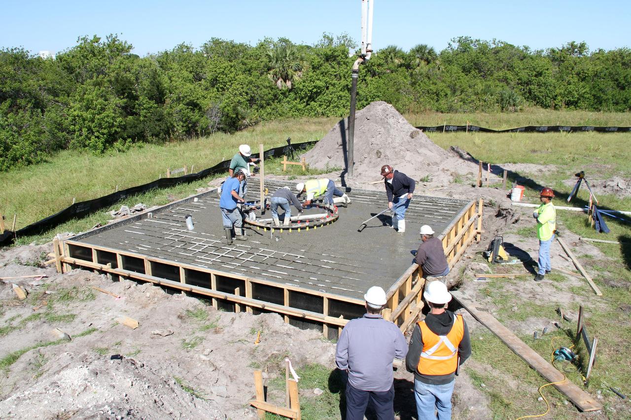
CAPE CANAVERAL, Fla. – At NASA’s Kennedy Space Center in Florida, workers pour and spread concrete at the base of the site of the Antenna Test Bed Array for the Ka-Band Objects Observation and Monitoring, Ka-BOOM system. The construction site is near the former Vertical Processing Facility, which has been demolished. Workers are placing the pile foundations for the 40-foot-diameter dish antenna arrays and their associated utilities, and preparing the site for the operations command center facility. Photo credit: NASA/Ben Smegelski
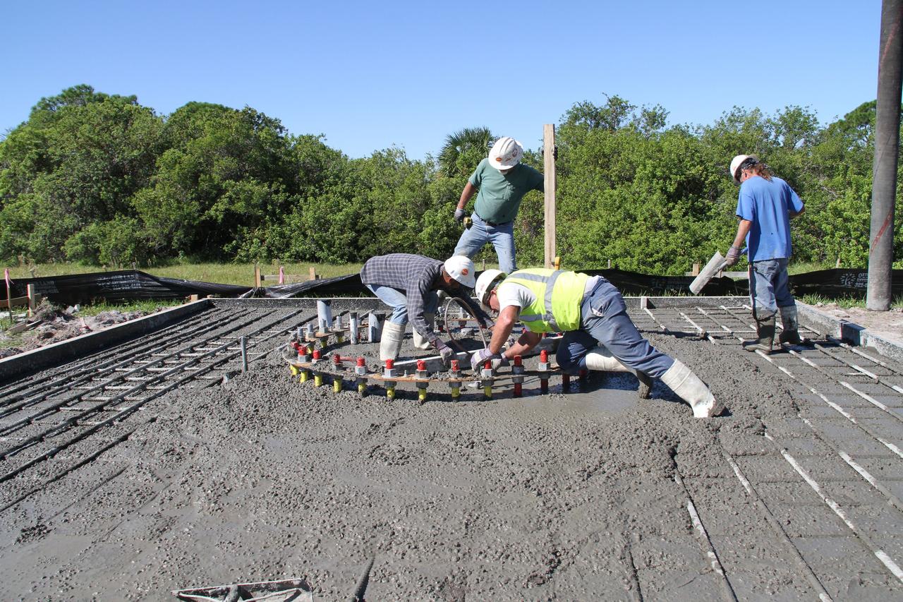
CAPE CANAVERAL, Fla. – At NASA’s Kennedy Space Center in Florida, workers continue construction of the Antenna Test Bed Array for the Ka-Band Objects Observation and Monitoring, or Ka-BOOM, system. The construction site is near the former Vertical Processing Facility, which has been demolished. Workers are placing the pile foundations for the 40-foot-diameter dish antenna arrays and their associated utilities, and preparing the site for the operations command center facility. Photo credit: NASA/Ben Smegelski
CAPE CANAVERAL, Fla. – At NASA’s Kennedy Space Center in Florida, a worker continues construction of the Antenna Test Bed Array for the Ka-Band Objects Observation and Monitoring, or Ka-BOOM, system. The construction site is near the former Vertical Processing Facility, which has been demolished. Workers are placing the pile foundations for the 40-foot-diameter dish antenna arrays and their associated utilities, and preparing the site for the operations command center facility. Photo credit: NASA/Ben Smegelski
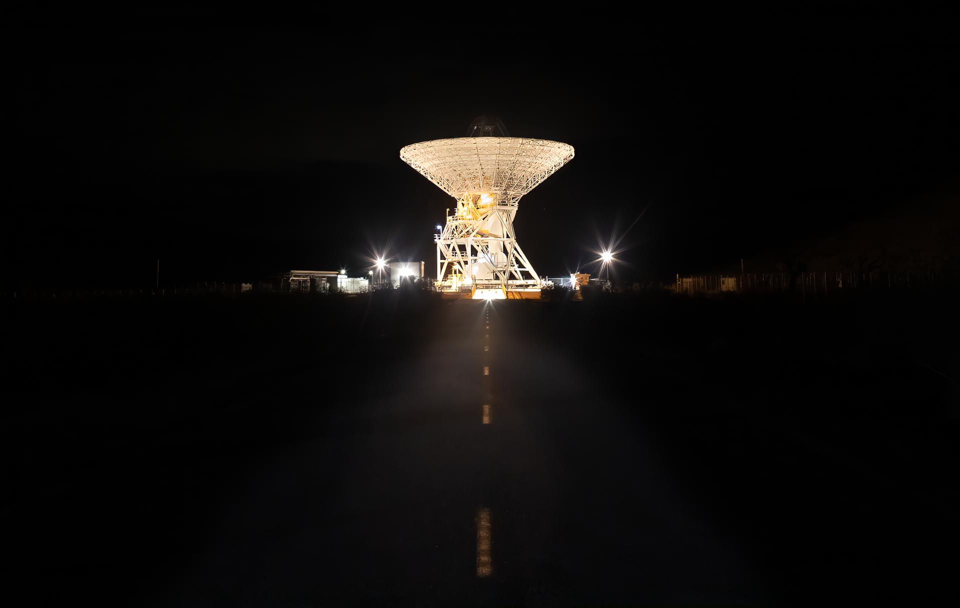
A 112-foot (34-meter) antenna glows from within a nighttime scene at the Goldstone Deep Space Communications Complex near Barstow, California, in September 2025. Goldstone is part of NASA’s Deep Space Network (DSN), which operates three complexes around the globe that support communications with dozens of deep space missions. For more information about the DSN, visit: https://www.nasa.gov/communicating-with-missions/dsn/
File: 03/26/2012 The GPM High Gain Antenna System (HGAS) in integration and testing at Goddard Space Flight Center. GPM is a joint mission between NASA and the Japan Aerospace Exploration Agency (JAXA). The Core Observatory will link data from a constellation of current and planned satellites to produce next-generation global measurements of rainfall and snowfall from space. The GPM mission is the first coordinated international satellite network to provide near real-time observations of rain and snow every three hours anywhere on the globe. The GPM Core Observatory anchors this network by providing observations on all types of precipitation. The observatory's data acts as the measuring stick by which partner observations can be combined into a unified data set. The data will be used by scientists to study climate change, freshwater resources, floods and droughts, and hurricane formation and tracking. Credit: Craig E. Huber, Chief Engineer SGT Inc, NASA Goddard Space Flight Center <b><a href="http://www.nasa.gov/audience/formedia/features/MP_Photo_Guidelines.html" rel="nofollow">NASA image use policy.</a></b> <b><a href="http://www.nasa.gov/centers/goddard/home/index.html" rel="nofollow">NASA Goddard Space Flight Center</a></b> enables NASA’s mission through four scientific endeavors: Earth Science, Heliophysics, Solar System Exploration, and Astrophysics. Goddard plays a leading role in NASA’s accomplishments by contributing compelling scientific knowledge to advance the Agency’s mission. <b>Follow us on <a href="http://twitter.com/NASAGoddardPix" rel="nofollow">Twitter</a></b> <b>Like us on <a href="http://www.facebook.com/pages/Greenbelt-MD/NASA-Goddard/395013845897?ref=tsd" rel="nofollow">Facebook</a></b> <b>Find us on <a href="http://instagram.com/nasagoddard?vm=grid" rel="nofollow">Instagram</a></b>
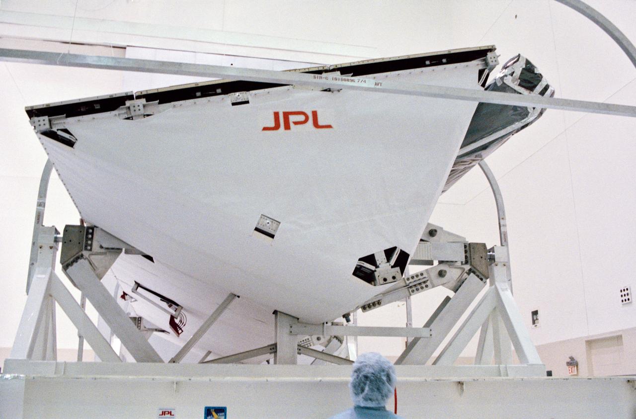
S93-48551 (October 1993) --- The Spaceborne Imaging Radar-C and X-Band Synthetic Aperture Radar (SIR-C/X-SAR) antenna, developed by the Jet Propulsion Laboratory (JPL) as part of NASA's Mission to Planet Earth (MTPE), will fly aboard the Space Shuttle Endeavour. The radar antenna uses microwave energy which gives it the ability to collect data over virtually any region at any time, regardless of weather or sunlight conditions. The radar waves can penetrate clouds, and under certain conditions the radar can also see through vegetation, ice and dry sand. In many cases, spaceborne radar is the only way scientists can explore large-scale and inaccessible regions of the Earth's surface. SIR-C/X-SAR uses three microwave wavelengths: L-Band (24 cm), C-Band (6 cm) and X-Ban (3 cm). The multi-frequency data will be used by the international scientific community to monitor global environmental processes with a focus on climate change. The MTPE spaceborne data, complemented by aircraft and ground studies, will give scientists clearer insights into those environmental changes which are caused by nature and those changes which are induced by human activity.
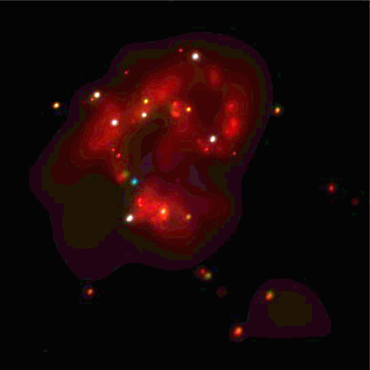
This Chandra image shows the central regions of two colliding galaxies known collectively as the Antennae (NGC-4038/4039). The Chandra image reveals a large population of extremely bright x-ray sources in this area of intense star formation. These x-ray sources, which emit 10 to several hundred times more x-ray power than similar sources in our own galaxy, are believed to be either massive black holes, or black holes that are beaming their energy toward Earth. In this x-ray image, red represents the low energy band, green intermediate, and blue the highest observed energies. The white and yellow sources are those that emit significant amounts of both low and high energy x-rays. About 60 million light years from Earth in the constellation Corvus, the Antennae Galaxies got their nickname from the wispy anntennae-like streams of gas as seen by optical telescopes. These ongoing wisps are believed to have been produced approximately 100 million years ago by the collision between the gala
Flight Electronics Payload for Curved Confocal Lightweight Antenna Structures for Aeronautical Communications Technologies, CLAS-ACT, Phased Array Antenna on T-34-C Aircraft Door Flight Curved Confocal Lightweight Antenna Structures for Aeronautical Communications Technologies, CLAS-ACT, Phased Array Antenna Control / Flight Testing
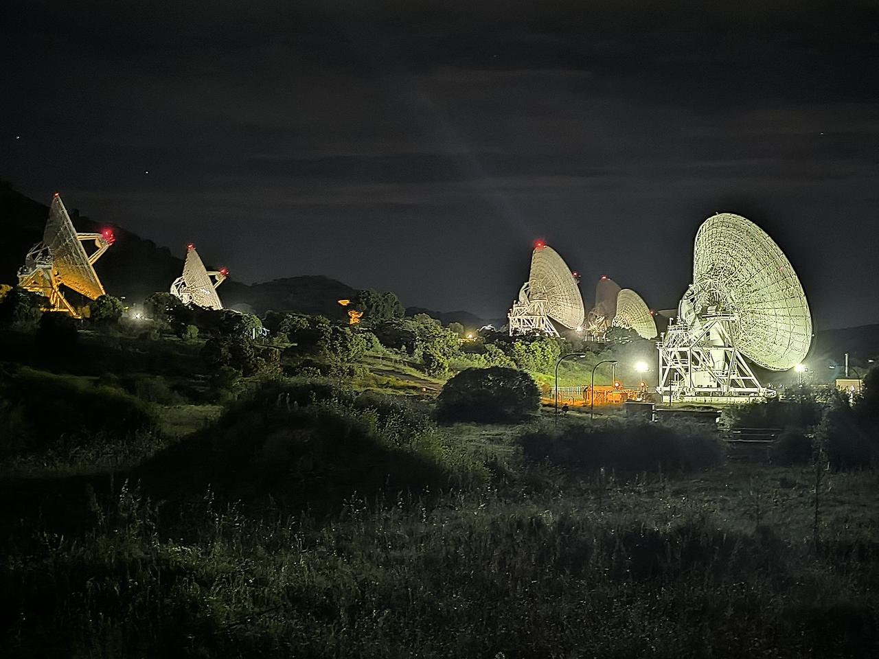
In a historic first, all six radio frequency antennas at the Madrid Deep Space Communication Complex – part of NASA's Deep Space Network (DSN) – carried out a test to receive data from the agency's Voyager 1 spacecraft at the same time on April 20, 2024. Known as "arraying," combining the receiving power of several antennas allows the DSN to collect the very faint signals from faraway spacecraft. A five-antenna array is currently needed to downlink science data from the spacecraft's Plasma Wave System (PWS) instrument. As Voyager gets further way, six antennas will be needed. The Voyager team is currently working to fix an issue on the spacecraft that has prevented it from sending back science data since November. Though the antennas located at the DSN's three complexes – Goldstone in California, Canberra in Australia, and Madrid – have been arrayed before, this is the first instance of six antennas being arrayed at once. Madrid is the only deep space communication complex currently with six operational antennas (the other two complexes have four apiece). Each complex consists of one 70-meter (230-foot) antenna and several 34-meter (112-foot) antennas. Voyager 1 is over 15 billion miles (24 billion kilometers) away, so its signal on Earth is far fainter than any other spacecraft with which the DSN communicates. It currently takes Voyager 1's signal over 22 ½ hours to travel from the spacecraft to Earth. To better receive Voyager 1's radio communications, a large antenna – or an array of multiple smaller antennas – can be used. Voyager 1 and its twin, Voyager 2, are the only spacecraft ever to fly in interstellar space (the space between stars). https://photojournal.jpl.nasa.gov/catalog/PIA26147
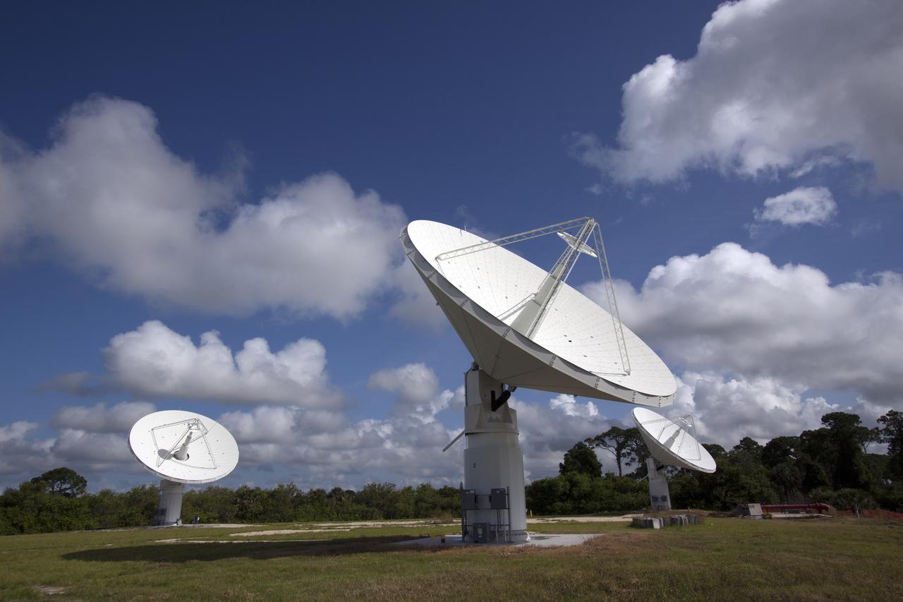
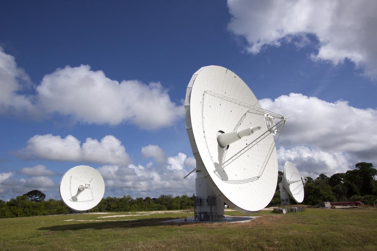
CAPE CANAVERAL, Fla. -- At NASA’s Kennedy Space Center in Florida, the three Ka-Band Objects Observation and Monitoring, or Ka-BOOM, testbed antennas are used to track the pattern of the sun during initial testing of the new system. The goal of Ka-BOOM is to prove technologies that will allow future systems to characterize near-Earth objects in terms of size, shape, rotation_tumble rate and to determine the trajectory of those objects. Radar studies can determine the trajectory 100,000 times more precisely than can optical methods. While also capable of space communication and radio science experiments, developing radar applications is the primary focus of the arrays. The 40-foot-diameter dish antenna arrays are at the site of the former Vertical Processing Facility, which has been demolished. Photo credit: NASA_Jim Grossmann
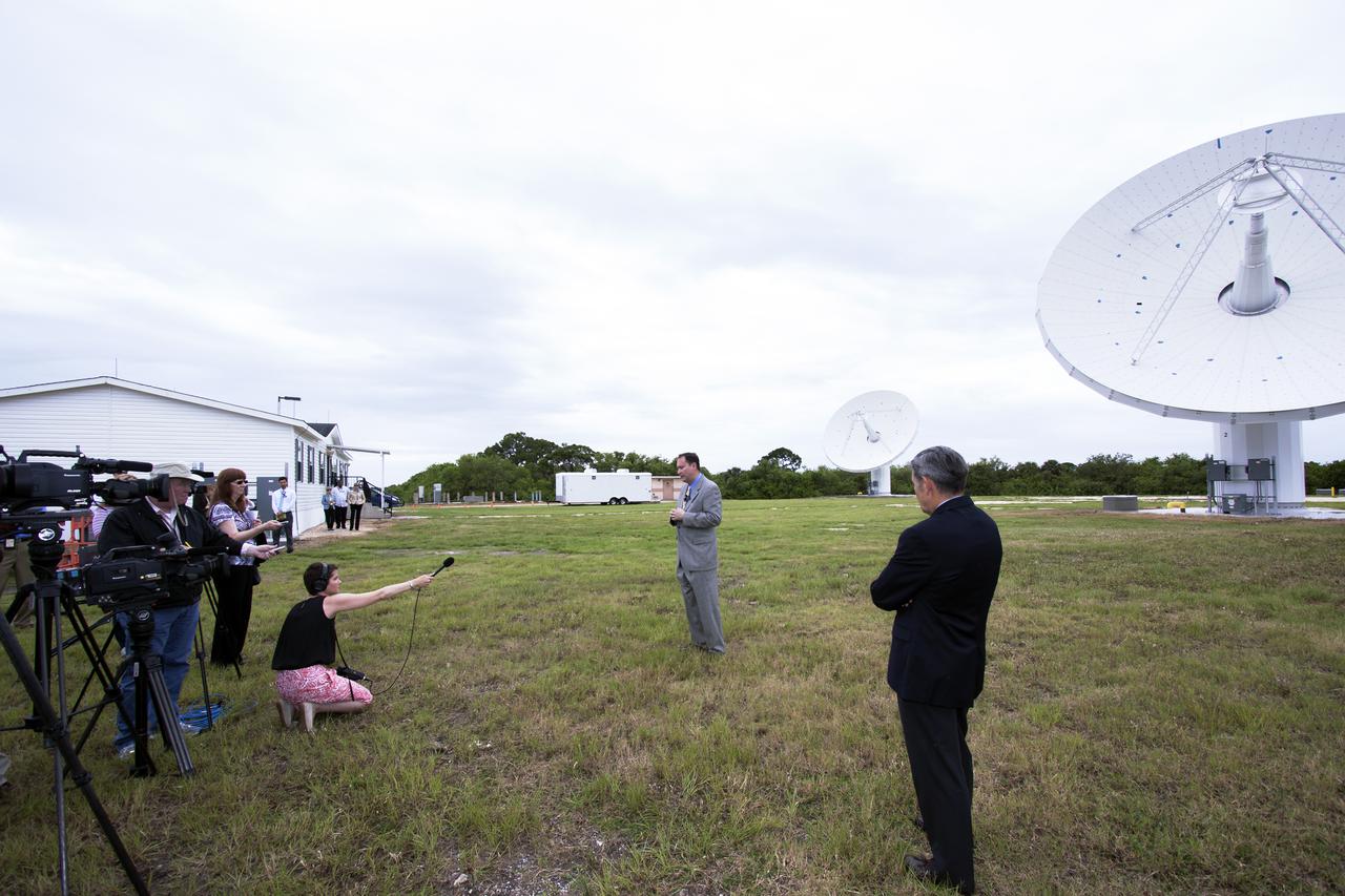
CAPE CANAVERAL, Fla. – At NASA’s Kennedy Space Center in Florida, Robert Lightfoot, NASA associate director, talks to members of the media at the Ka Band Objects Observation and Monitoring, or KaBOOM, testbed antenna array site during a tour of Kennedy facilities. At right, in the foreground is Kennedy Director Bob Cabana. The goal of KaBOOM is to prove technologies that will allow future systems to characterize near-Earth objects in terms of size, shape, rotation_tumble rate and to determine the trajectory of those objects. Radar studies can determine the trajectory 100,000 times more precisely than can optical methods. While also capable of space communication and radio science experiments, developing radar applications is the primary focus of the arrays. The 40-foot-diameter dish antenna arrays are at the site of the former Vertical Processing Facility, which has been demolished. Photo credit: NASA_Jim Grossmann
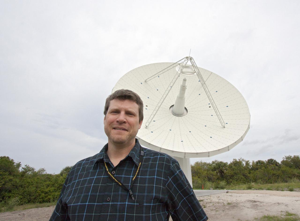
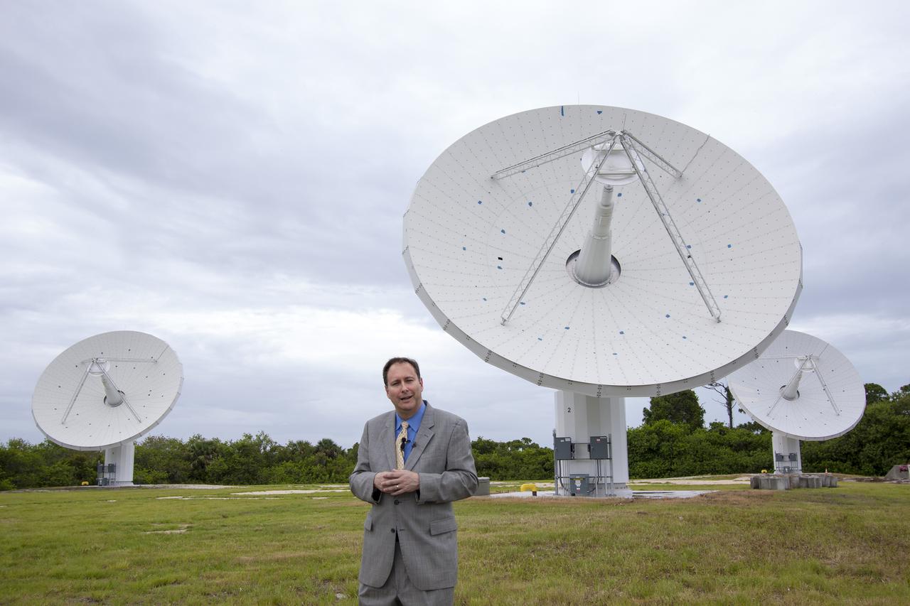
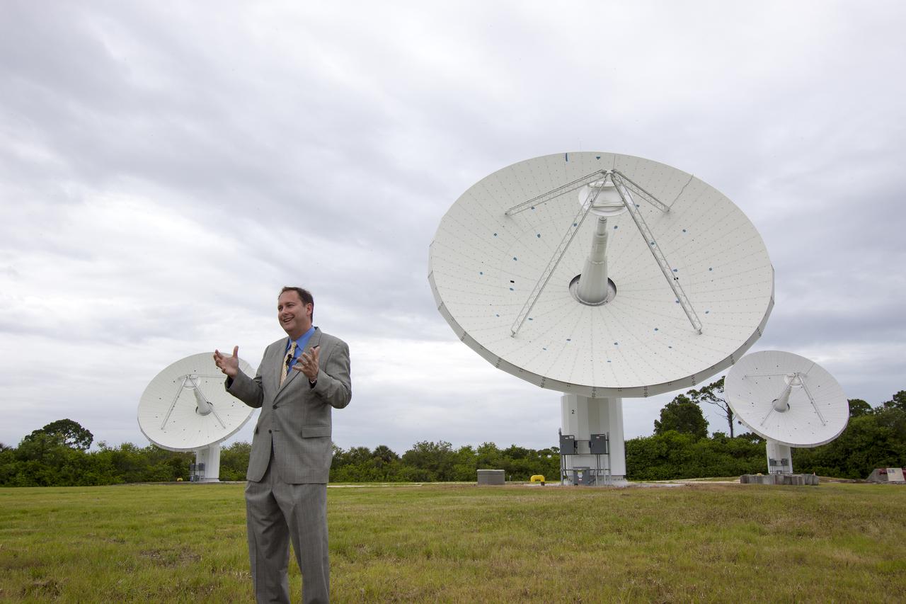
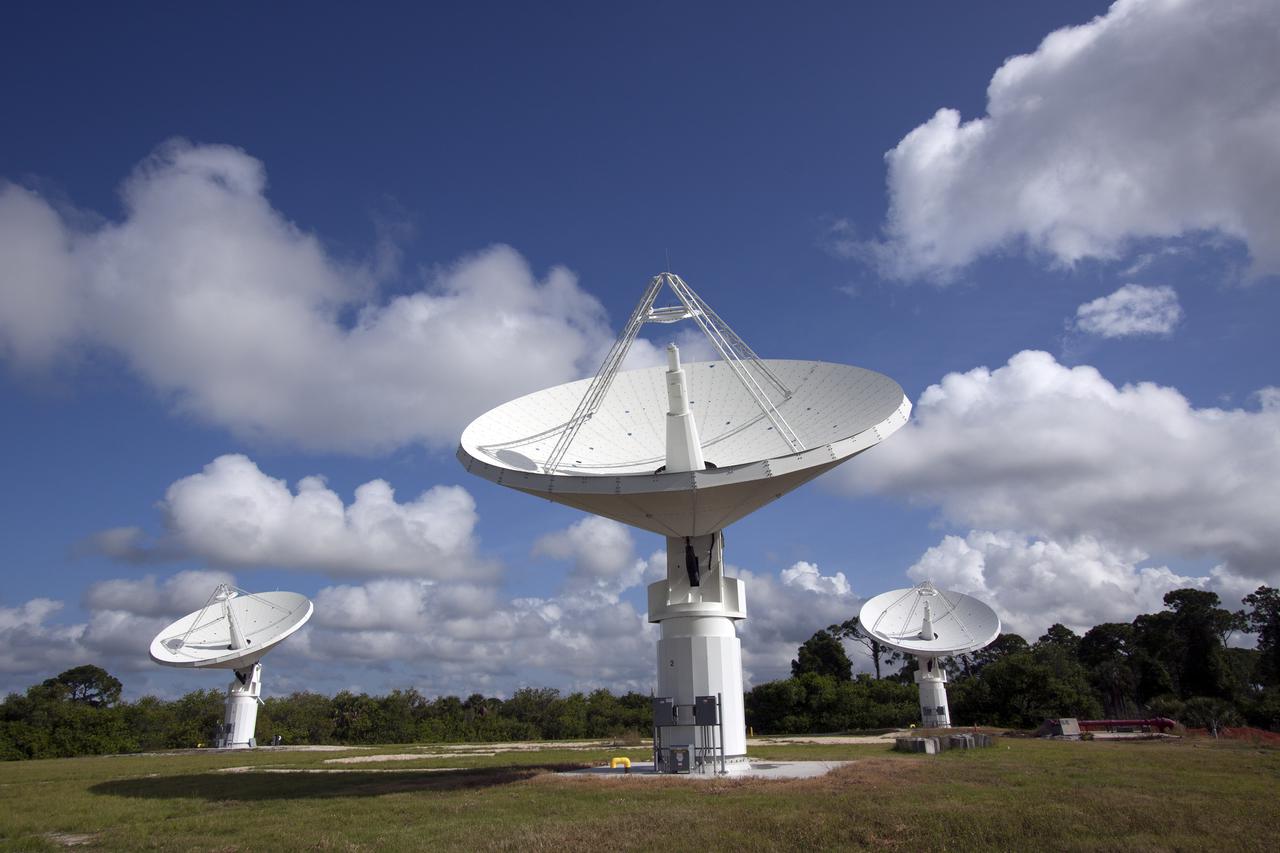
CAPE CANAVERAL, Fla. – At NASA’s Kennedy Space Center in Florida, Marc Seibert, the manager for Tracking and Timing Integration in the Research and Technology Management Office, stands near one of the three antennas that comprise the KA-Band Objects Observation and Monitoring, or Ka-BOOM, System. The Ka-BOOM project is one of the final steps in developing the techniques to build a high power, high resolution radar system capable of becoming a Near Earth Object Early Warning System. While also capable of space communication and radio science experiments, developing radar applications is the primary focus of the arrays. The 40-foot-diameter dish antenna arrays are near the former Vertical Processing Facility, which has been demolished. Photo credit: NASA_Jim Grossmann
CAPE CANAVERAL, Fla. -- At NASA’s Kennedy Space Center in Florida, the three Ka-Band Objects Observation and Monitoring, or Ka-BOOM, testbed antennas are used to track the pattern of the sun during initial testing of the new system. The goal of Ka-BOOM is to prove technologies that will allow future systems to characterize near-Earth objects in terms of size, shape, rotation_tumble rate and to determine the trajectory of those objects. Radar studies can determine the trajectory 100,000 times more precisely than can optical methods. While also capable of space communication and radio science experiments, developing radar applications is the primary focus of the arrays. The 40-foot-diameter dish antenna arrays are at the site of the former Vertical Processing Facility, which has been demolished. Photo credit: NASA_Jim Grossmann
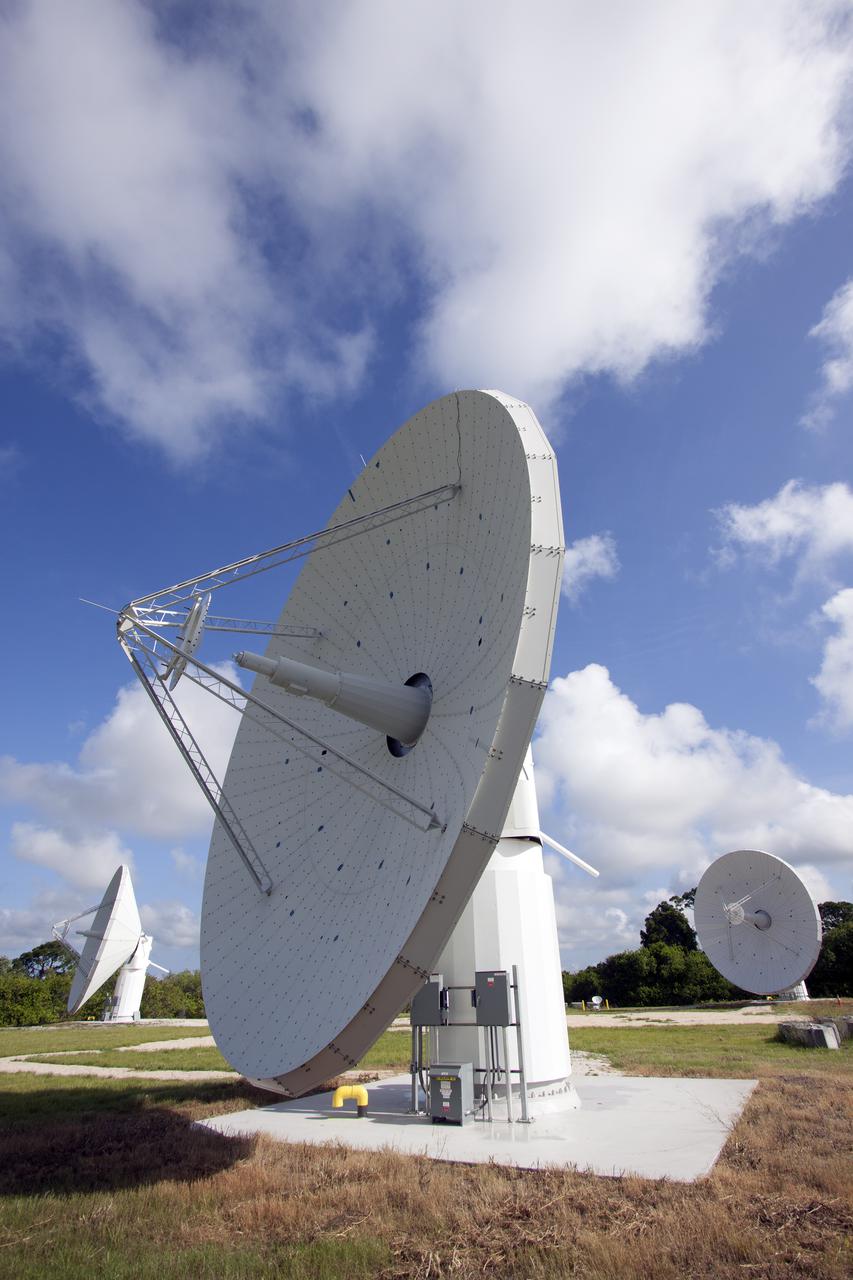
CAPE CANAVERAL, Fla. -- At NASA’s Kennedy Space Center in Florida, one of the three Ka-Band Objects Observation and Monitoring, or Ka-BOOM, testbed antennas is used to track the sun during initial testing of the new system. The goal of Ka-BOOM is to prove technologies that will allow future systems to characterize near-Earth objects in terms of size, shape, rotation_tumble rate and to determine the trajectory of those objects. Radar studies can determine the trajectory 100,000 times more precisely than can optical methods. While also capable of space communication and radio science experiments, developing radar applications is the primary focus of the arrays. The 40-foot-diameter dish antenna arrays are at the site of the former Vertical Processing Facility, which has been demolished. Photo credit: NASA_Jim Grossmann
CAPE CANAVERAL, Fla. -- At NASA’s Kennedy Space Center in Florida, the three Ka-Band Objects Observation and Monitoring, or Ka-BOOM, testbed antennas are used to track the pattern of the sun during initial testing of the new system. The goal of Ka-BOOM is to prove technologies that will allow future systems to characterize near-Earth objects in terms of size, shape, rotation_tumble rate and to determine the trajectory of those objects. Radar studies can determine the trajectory 100,000 times more precisely than can optical methods. While also capable of space communication and radio science experiments, developing radar applications is the primary focus of the arrays. The 40-foot-diameter dish antenna arrays are at the site of the former Vertical Processing Facility, which has been demolished. Photo credit: NASA_Jim Grossmann
CAPE CANAVERAL, Fla. -- At NASA’s Kennedy Space Center in Florida, the three Ka-Band Objects Observation and Monitoring, or Ka-BOOM, testbed antennas are used to track the pattern of the sun during initial testing of the new system. The goal of Ka-BOOM is to prove technologies that will allow future systems to characterize near-Earth objects in terms of size, shape, rotation_tumble rate and to determine the trajectory of those objects. Radar studies can determine the trajectory 100,000 times more precisely than can optical methods. While also capable of space communication and radio science experiments, developing radar applications is the primary focus of the arrays. The 40-foot-diameter dish antenna arrays are at the site of the former Vertical Processing Facility, which has been demolished. Photo credit: NASA_Jim Grossmann
CAPE CANAVERAL, Fla. – At NASA’s Kennedy Space Center in Florida, Robert Lightfoot, NASA associate director, talks to members of the media at the Ka Band Objects Observation and Monitoring, or KaBOOM, testbed antenna array site during a tour of Kennedy facilities. The goal of KaBOOM is to prove technologies that will allow future systems to characterize near-Earth objects in terms of size, shape, rotation_tumble rate and to determine the trajectory of those objects. Radar studies can determine the trajectory 100,000 times more precisely than can optical methods. While also capable of space communication and radio science experiments, developing radar applications is the primary focus of the arrays. The 40-foot-diameter dish antenna arrays are at the site of the former Vertical Processing Facility, which has been demolished. Photo credit: NASA_Jim Grossmann
CAPE CANAVERAL, Fla. – At NASA’s Kennedy Space Center in Florida, Robert Lightfoot, NASA associate director, talks to members of the media at the Ka Band Objects Observation and Monitoring, or KaBOOM, testbed antenna array site during a tour of Kennedy facilities. The goal of KaBOOM is to prove technologies that will allow future systems to characterize near-Earth objects in terms of size, shape, rotation_tumble rate and to determine the trajectory of those objects. Radar studies can determine the trajectory 100,000 times more precisely than can optical methods. While also capable of space communication and radio science experiments, developing radar applications is the primary focus of the arrays. The 40-foot-diameter dish antenna arrays are at the site of the former Vertical Processing Facility, which has been demolished. Photo credit: NASA_Jim Grossmann
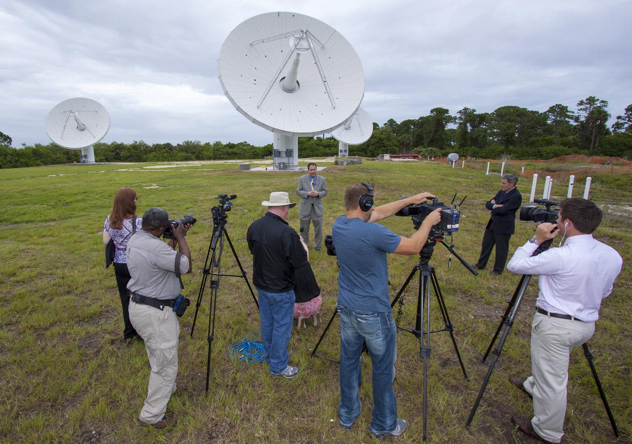
CAPE CANAVERAL, Fla. – At NASA’s Kennedy Space Center in Florida, Robert Lightfoot, NASA associate director, talks to members of the media at the Ka Band Objects Observation and Monitoring, or KaBOOM, testbed antenna array site during a tour of Kennedy facilities. At right is Kennedy Director Bob Cabana. The goal of KaBOOM is to prove technologies that will allow future systems to characterize near-Earth objects in terms of size, shape, rotation_tumble rate and to determine the trajectory of those objects. Radar studies can determine the trajectory 100,000 times more precisely than can optical methods. While also capable of space communication and radio science experiments, developing radar applications is the primary focus of the arrays. The 40-foot-diameter dish antenna arrays are at the site of the former Vertical Processing Facility, which has been demolished. Photo credit: NASA_Jim Grossmann
CAPE CANAVERAL, Fla. -- At NASA’s Kennedy Space Center in Florida, the three Ka-Band Objects Observation and Monitoring, or Ka-BOOM, testbed antennas are used to track the pattern of the sun during initial testing of the new system. The goal of Ka-BOOM is to prove technologies that will allow future systems to characterize near-Earth objects in terms of size, shape, rotation_tumble rate and to determine the trajectory of those objects. Radar studies can determine the trajectory 100,000 times more precisely than can optical methods. While also capable of space communication and radio science experiments, developing radar applications is the primary focus of the arrays. The 40-foot-diameter dish antenna arrays are at the site of the former Vertical Processing Facility, which has been demolished. Photo credit: NASA_Jim Grossmann
CAPE CANAVERAL, Fla. -- At NASA’s Kennedy Space Center in Florida, the three Ka-Band Objects Observation and Monitoring, or Ka-BOOM, testbed antennas are used to track the pattern of the sun during initial testing of the new system. The goal of Ka-BOOM is to prove technologies that will allow future systems to characterize near-Earth objects in terms of size, shape, rotation_tumble rate and to determine the trajectory of those objects. Radar studies can determine the trajectory 100,000 times more precisely than can optical methods. While also capable of space communication and radio science experiments, developing radar applications is the primary focus of the arrays. The 40-foot-diameter dish antenna arrays are at the site of the former Vertical Processing Facility, which has been demolished. Photo credit: NASA_Jim Grossmann
CAPE CANAVERAL, Fla. -- At NASA’s Kennedy Space Center in Florida, the three Ka-Band Objects Observation and Monitoring, or Ka-BOOM, testbed antennas are used to track the pattern of the sun during initial testing of the new system. The goal of Ka-BOOM is to prove technologies that will allow future systems to characterize near-Earth objects in terms of size, shape, rotation_tumble rate and to determine the trajectory of those objects. Radar studies can determine the trajectory 100,000 times more precisely than can optical methods. While also capable of space communication and radio science experiments, developing radar applications is the primary focus of the arrays. The 40-foot-diameter dish antenna arrays are at the site of the former Vertical Processing Facility, which has been demolished. Photo credit: NASA_Jim Grossmann
CAPE CANAVERAL, Fla. -- At NASA’s Kennedy Space Center in Florida, the three Ka-Band Objects Observation and Monitoring, or Ka-BOOM, testbed antennas are used to track the pattern of the sun during initial testing of the new system. The goal of Ka-BOOM is to prove technologies that will allow future systems to characterize near-Earth objects in terms of size, shape, rotation_tumble rate and to determine the trajectory of those objects. Radar studies can determine the trajectory 100,000 times more precisely than can optical methods. While also capable of space communication and radio science experiments, developing radar applications is the primary focus of the arrays. The 40-foot-diameter dish antenna arrays are at the site of the former Vertical Processing Facility, which has been demolished. Photo credit: NASA_Jim Grossmann
CAPE CANAVERAL, Fla. -- At NASA’s Kennedy Space Center in Florida, one of the three Ka-Band Objects Observation and Monitoring, or Ka-BOOM, testbed antennas is used to track the pattern of the sun during initial testing of the new system. The goal of Ka-BOOM is to prove technologies that will allow future systems to characterize near-Earth objects in terms of size, shape, rotation_tumble rate and to determine the trajectory of those objects. Radar studies can determine the trajectory 100,000 times more precisely than can optical methods. While also capable of space communication and radio science experiments, developing radar applications is the primary focus of the arrays. The 40-foot-diameter dish antenna arrays are at the site of the former Vertical Processing Facility, which has been demolished. Photo credit: NASA_Jim Grossmann
CAPE CANAVERAL, Fla. -- At NASA’s Kennedy Space Center in Florida, one of the three Ka-Band Objects Observation and Monitoring, or Ka-BOOM, testbed antennas is used to track the pattern of the sun during initial testing of the new system. The goal of Ka-BOOM is to prove technologies that will allow future systems to characterize near-Earth objects in terms of size, shape, rotation_tumble rate and to determine the trajectory of those objects. Radar studies can determine the trajectory 100,000 times more precisely than can optical methods. While also capable of space communication and radio science experiments, developing radar applications is the primary focus of the arrays. The 40-foot-diameter dish antenna arrays are at the site of the former Vertical Processing Facility, which has been demolished. Photo credit: NASA_Jim Grossmann
CAPE CANAVERAL, Fla. -- At NASA’s Kennedy Space Center in Florida, the three Ka-Band Objects Observation and Monitoring, or Ka-BOOM, testbed antennas are used to track the pattern of the sun during initial testing of the new system. The goal of Ka-BOOM is to prove technologies that will allow future systems to characterize near-Earth objects in terms of size, shape, rotation_tumble rate and to determine the trajectory of those objects. Radar studies can determine the trajectory 100,000 times more precisely than can optical methods. While also capable of space communication and radio science experiments, developing radar applications is the primary focus of the arrays. The 40-foot-diameter dish antenna arrays are at the site of the former Vertical Processing Facility, which has been demolished. Photo credit: NASA_Jim Grossmann
CAPE CANAVERAL, Fla. -- At NASA’s Kennedy Space Center in Florida, one of the three Ka-Band Objects Observation and Monitoring, or Ka-BOOM, testbed antennas is used to track the sun during initial testing of the new system. The goal of Ka-BOOM is to prove technologies that will allow future systems to characterize near-Earth objects in terms of size, shape, rotation_tumble rate and to determine the trajectory of those objects. Radar studies can determine the trajectory 100,000 times more precisely than can optical methods. While also capable of space communication and radio science experiments, developing radar applications is the primary focus of the arrays. The 40-foot-diameter dish antenna arrays are at the site of the former Vertical Processing Facility, which has been demolished. Photo credit: NASA_Jim Grossmann
CAPE CANAVERAL, Fla. -- At NASA’s Kennedy Space Center in Florida, the three Ka-Band Objects Observation and Monitoring, or Ka-BOOM, testbed antennas are used to track the pattern of the sun during initial testing of the new system. The goal of Ka-BOOM is to prove technologies that will allow future systems to characterize near-Earth objects in terms of size, shape, rotation_tumble rate and to determine the trajectory of those objects. Radar studies can determine the trajectory 100,000 times more precisely than can optical methods. While also capable of space communication and radio science experiments, developing radar applications is the primary focus of the arrays. The 40-foot-diameter dish antenna arrays are at the site of the former Vertical Processing Facility, which has been demolished. Photo credit: NASA_Jim Grossmann
CAPE CANAVERAL, Fla. -- At NASA’s Kennedy Space Center in Florida, the three Ka-Band Objects Observation and Monitoring, or Ka-BOOM, testbed antennas are used to track the pattern of the sun during initial testing of the new system. The goal of Ka-BOOM is to prove technologies that will allow future systems to characterize near-Earth objects in terms of size, shape, rotation_tumble rate and to determine the trajectory of those objects. Radar studies can determine the trajectory 100,000 times more precisely than can optical methods. While also capable of space communication and radio science experiments, developing radar applications is the primary focus of the arrays. The 40-foot-diameter dish antenna arrays are at the site of the former Vertical Processing Facility, which has been demolished. Photo credit: NASA_Jim Grossmann
CAPE CANAVERAL, Fla. -- At NASA’s Kennedy Space Center in Florida, the three Ka-Band Objects Observation and Monitoring, or Ka-BOOM, testbed antennas are used to track the pattern of the sun during initial testing of the new system. The goal of Ka-BOOM is to prove technologies that will allow future systems to characterize near-Earth objects in terms of size, shape, rotation_tumble rate and to determine the trajectory of those objects. Radar studies can determine the trajectory 100,000 times more precisely than can optical methods. While also capable of space communication and radio science experiments, developing radar applications is the primary focus of the arrays. The 40-foot-diameter dish antenna arrays are at the site of the former Vertical Processing Facility, which has been demolished. Photo credit: NASA_Jim Grossmann
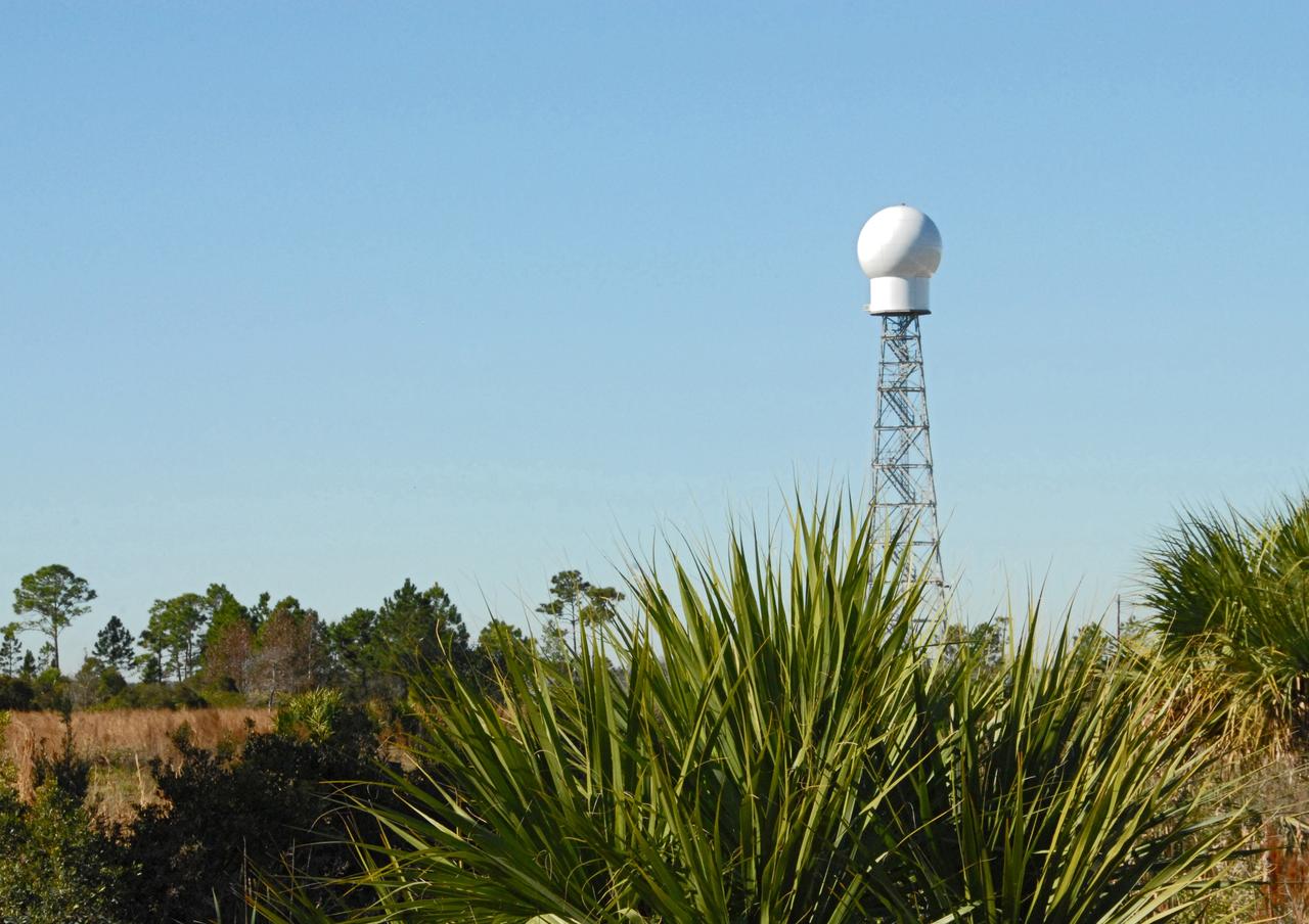
CAPE CANAVERAL, Fla. -- A replacement weather Doppler radar has been installed on top of this tower in a remote field located west of NASA's Kennedy Space Center in Florida. The radome houses the rotating antenna and pedestal and protects them from the elements. The tower is 100 feet high; the radome is 22 feet in diameter, the antenna 14 feet in diameter. It rotates at 6 rpm. The structure can withstand 130 mph winds. It is undergoing initial testing and expected to become operational in the summer. The weather radar is essential in issuing lightning and other severe weather warnings and vital in evaluating lightning launch commit criteria for space shuttle and rocket launches. Photo credit: NASA/Troy Cryder
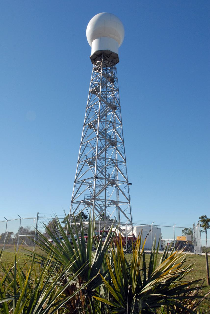
CAPE CANAVERAL, Fla. -- A replacement weather Doppler radar has been installed on top of this tower in a remote field located west of NASA's Kennedy Space Center in Florida. The radome houses the rotating antenna and pedestal and protects them from the elements. The tower is 100 feet high; the radome is 22 feet in diameter, the antenna 14 feet in diameter. It rotates at 6 rpm. The structure can withstand 130 mph winds. It is undergoing initial testing and expected to become operational in the summer. The weather radar is essential in issuing lightning and other severe weather warnings and vital in evaluating lightning launch commit criteria for space shuttle and rocket launches. Photo credit: NASA/Troy Cryder
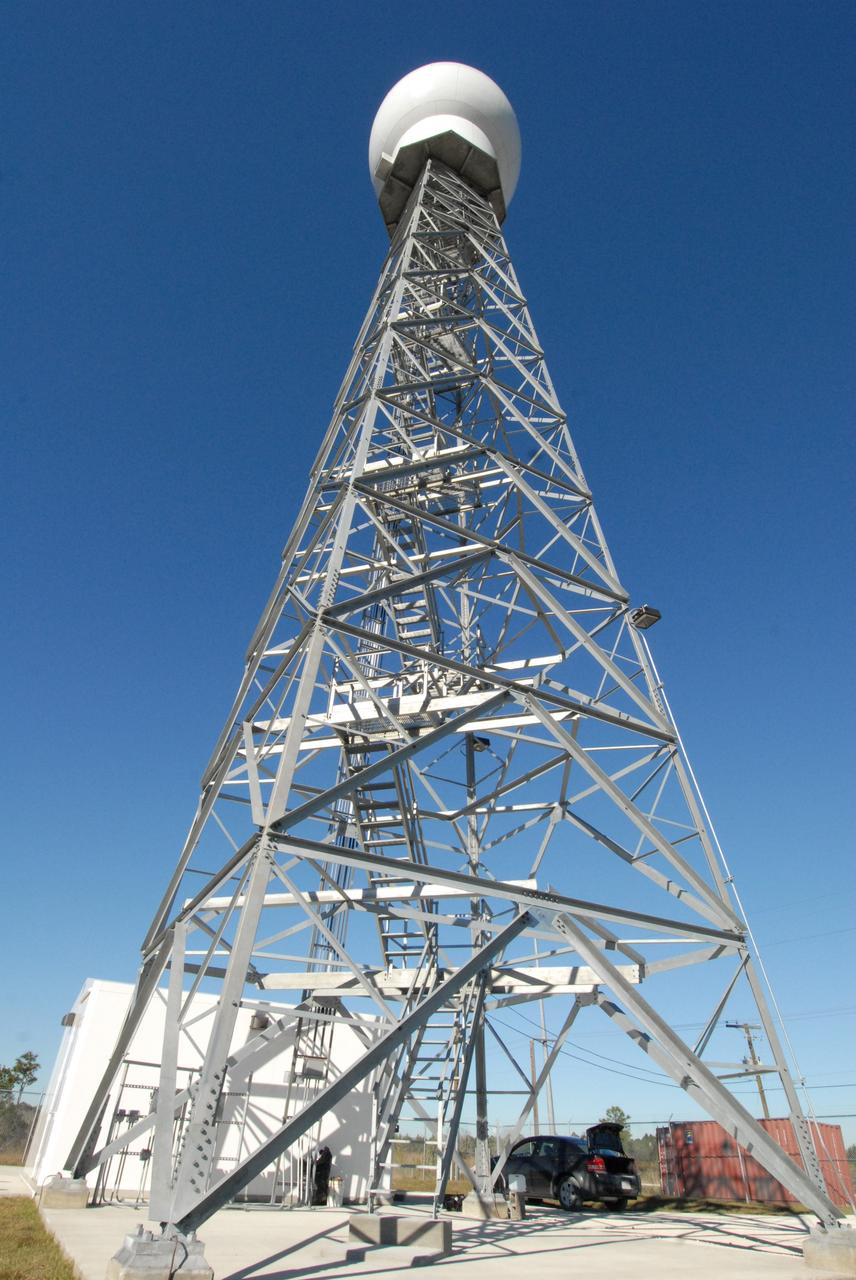
CAPE CANAVERAL, Fla. -- A replacement weather Doppler radar has been installed in the radome on top of this tower in a remote field located west of NASA's Kennedy Space Center in Florida. The dome houses the rotating antenna and pedestal and protects them from the elements. The tower is 100 feet high; the radome is 22 feet in diameter, the antenna 14 feet in diameter. It rotates at 6 rpm. The structure can withstand 130 mph winds. It is undergoing initial testing and expected to become operational in the summer. The weather radar is essential in issuing lightning and other severe weather warnings and vital in evaluating lightning launch commit criteria for space shuttle and rocket launches. Photo credit: NASA/Troy Cryder
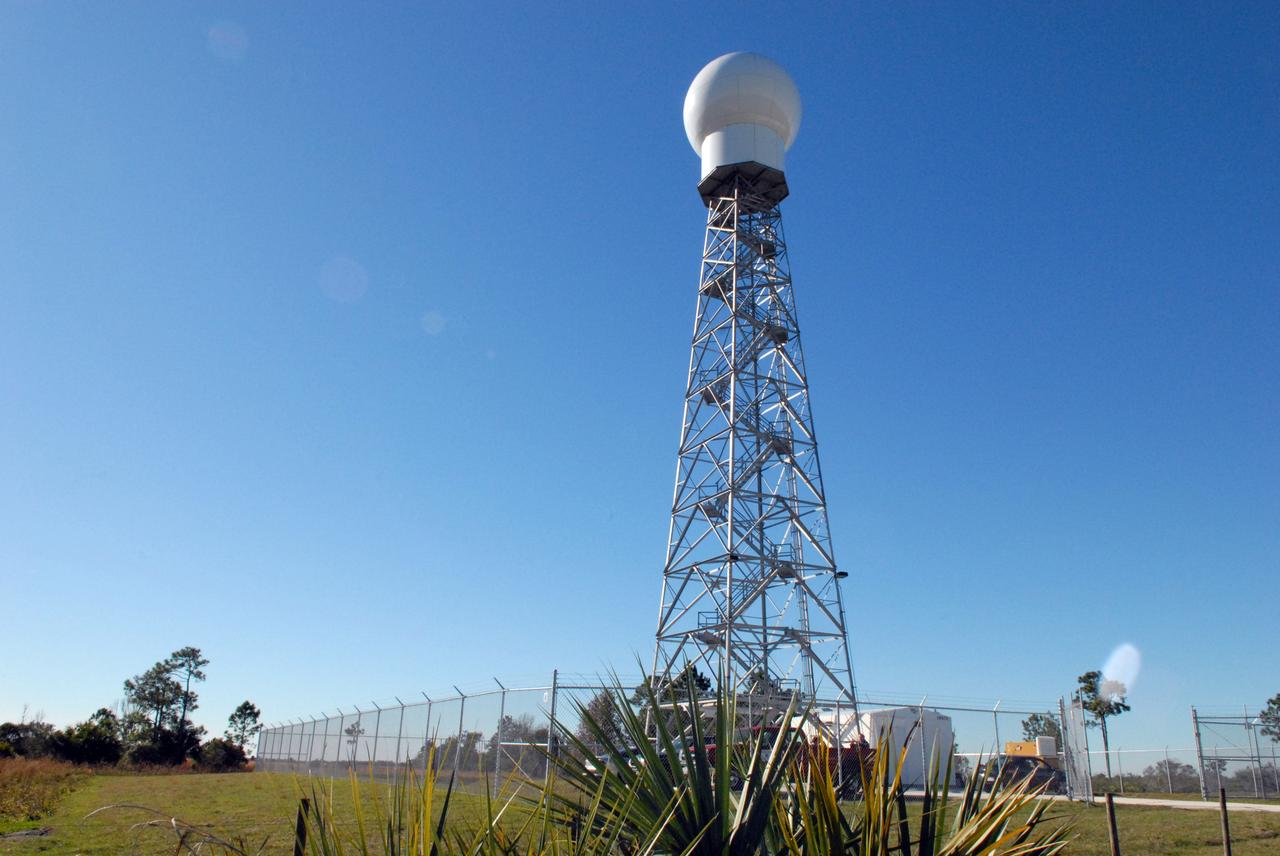
CAPE CANAVERAL, Fla. -- A replacement weather Doppler radar has been installed on top of this tower in a remote field located west of NASA's Kennedy Space Center in Florida. The radome houses the rotating antenna and pedestal and protects them from the elements. The tower is 100 feet high; the radome is 22 feet in diameter, the antenna 14 feet in diameter. It rotates at 6 rpm. The structure can withstand 130 mph winds. It is undergoing initial testing and expected to become operational in the summer. The weather radar is essential in issuing lightning and other severe weather warnings and vital in evaluating lightning launch commit criteria for space shuttle and rocket launches. Photo credit: NASA/Troy Cryder
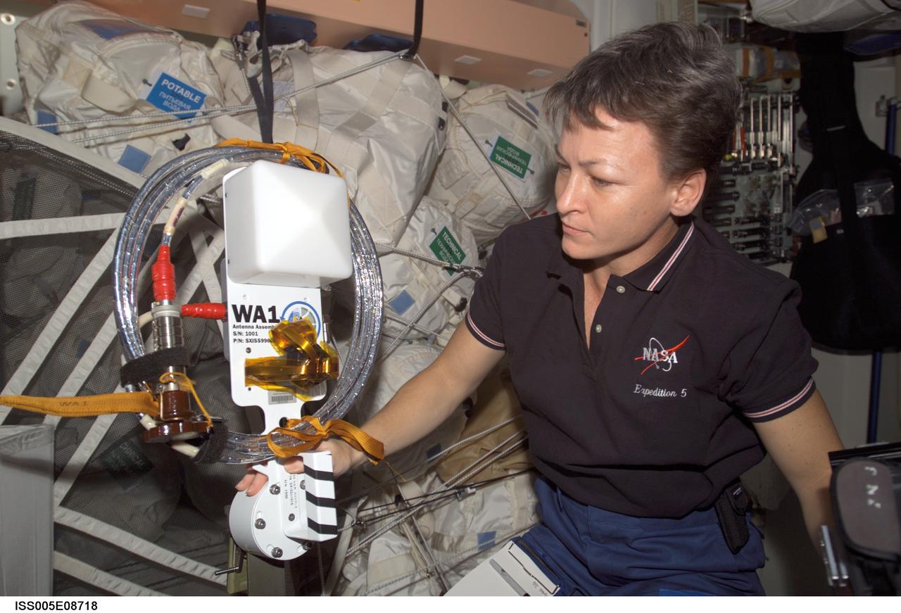
ISS005-E-08718 (6 August 2002) --- Astronaut Peggy A. Whitson, Expedition Five flight engineer, holds one of the two amateur radio antennas in the Unity node on the International Space Station (ISS). The antennas will be installed during a spacewalk scheduled for August 22, 2002.
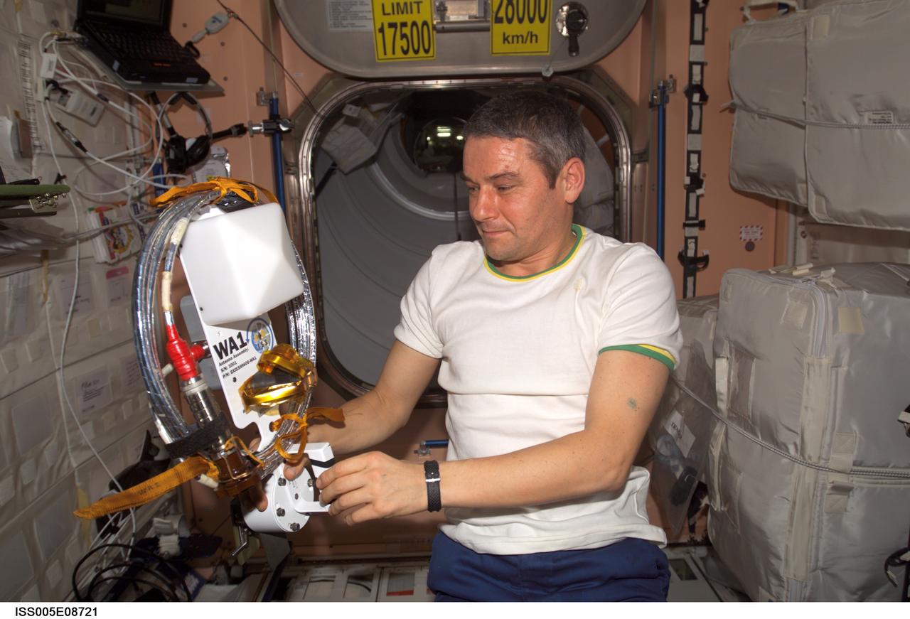
ISS005-E-08721 (6 August 2002) --- Cosmonaut Valery G. Korzun, Expedition Five mission commander, holds one of the two amateur radio antennas in the Unity node on the International Space Station (ISS). The antennas will be installed during a spacewalk scheduled for August 22, 2002. Korzun represents Rosaviakosmos.
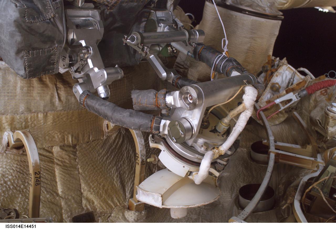
ISS014-E-14451 (22 Feb. 2007) --- A close-up view of the Kurs antenna on the Progress vehicle docked to the International Space Station's Zvezda Service Module was photographed during a session of extravehicular activity (EVA) on Feb. 22, 2007. During the 6-hour, 18-minute spacewalk, astronaut Michael E. Lopez-Alegria (out of frame), Expedition 14 commander and NASA space station science officer; and cosmonaut Mikhail Tyurin (out of frame), flight engineer representing Russia's Federal Space Agency, were able to retract the stuck antenna which did not properly retract when the Progress docked to the station on Oct. 26, 2006. Moving the antenna was necessary to ensure it would not interfere with the undocking scheduled in April.
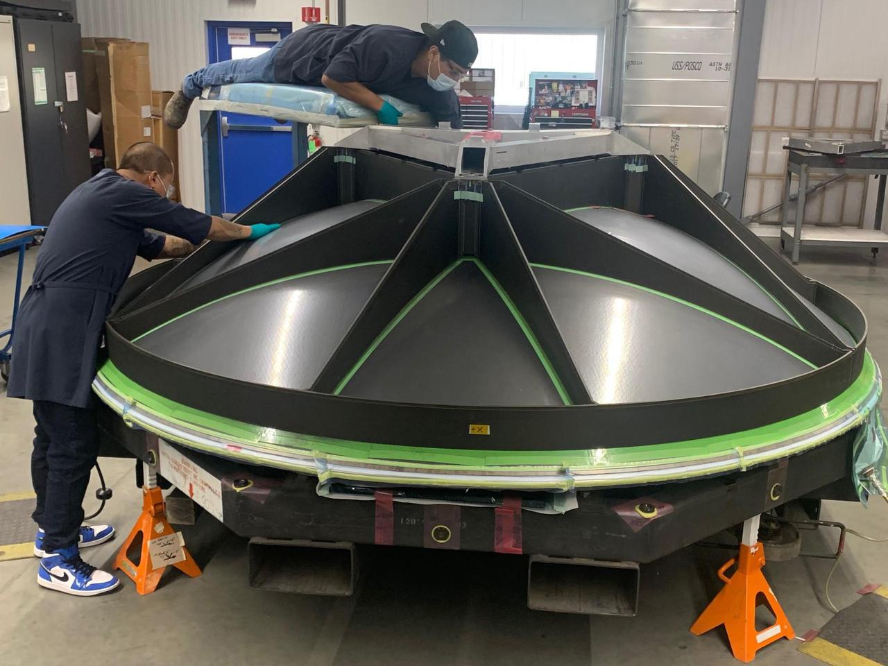
The build of a high-gain antenna, a nearly 10-foot-wide (3-meter-wide) dish, is underway for NASA's Europa Clipper spacecraft. The dish antenna, seen here face down, is being fabricated at aerospace vendor Applied Aerospace Structures Corporation (AASC) in Stockton, California. The antenna was designed by the Johns Hopkins Applied Physics Laboratory (APL) in Laurel, Maryland, and AASC, where it will be integrated along with other telecommunications hardware, into the propulsion module. The antenna downloads science data and allows ground controllers to send and receive commands and data between Earth and the spacecraft in Jupiter orbit – more than a million times farther from Earth than the International Space Station orbits. With an internal global ocean under a thick layer of ice, Jupiter's moon Europa may have the potential to harbor existing life. Europa Clipper will swoop around Jupiter on an elliptical path, dipping close to the moon on each flyby. Understanding Europa's habitability will help scientists better understand how life developed on Earth and the potential for finding life beyond our planet. Europa Clipper is set to launch in 2024. https://photojournal.jpl.nasa.gov/catalog/PIA24785
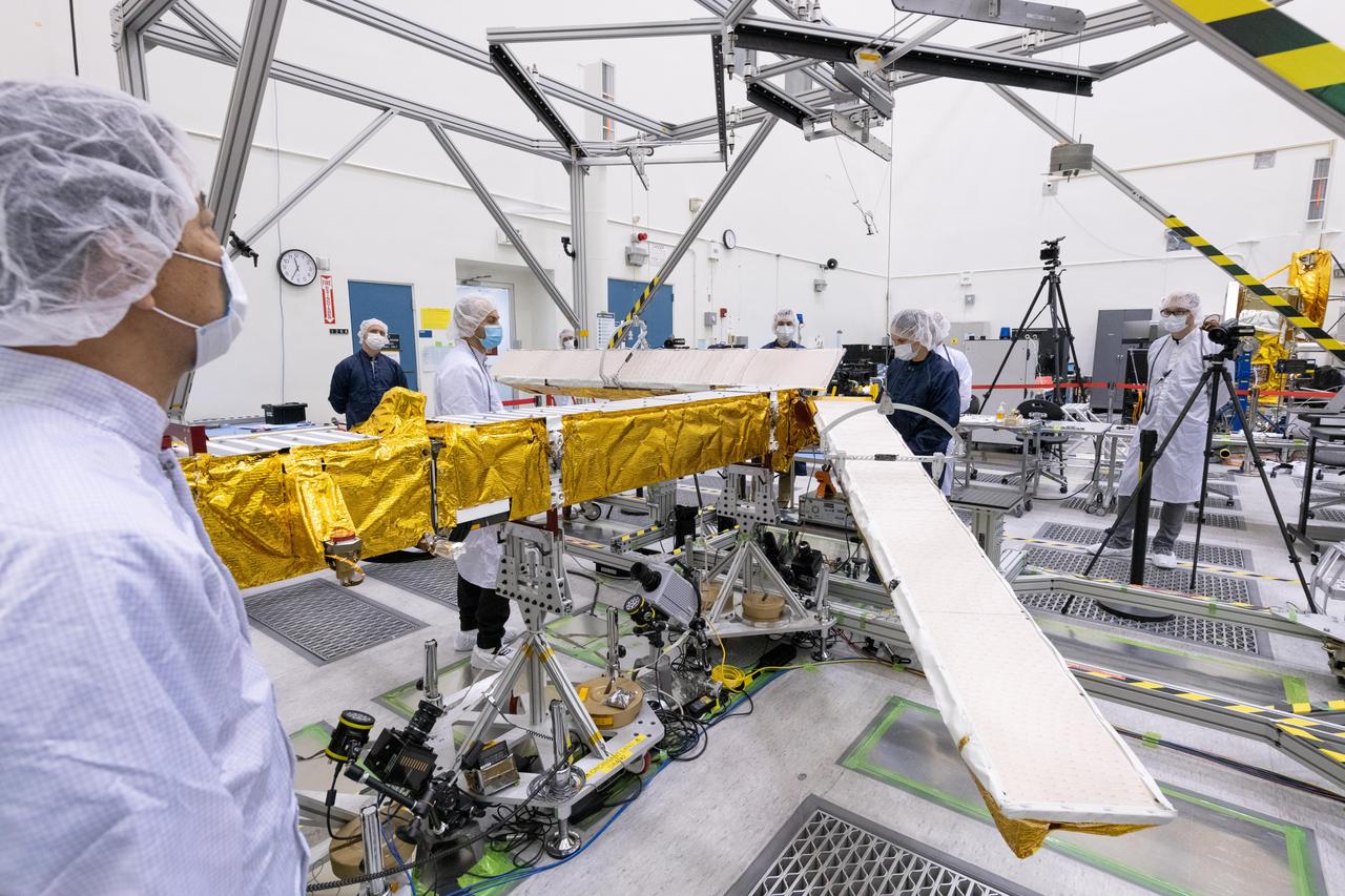
Members of the international Surface Water and Ocean Topography (SWOT) mission test one of the antennas for the Ka-band Radar Interferometer (KaRIn) instrument in a clean room at NASA's Jet Propulsion Laboratory in Southern California. The mission is a collaborative effort between NASA and the French space agency Centre National d'Études Spatiales (CNES) – with contributions from the Canadian Space Agency (CSA) and the UK Space Agency. KaRIn is the scientific heart of the SWOT satellite, which will survey the water on more than 90% of Earth's surface, measuring the height of water in lakes, rivers, reservoirs, and the ocean. To do that, KaRIn will transmit radar pulses to Earth's surface and use its two antennas to triangulate the return signals that bounce back. Mounted at the ends of a boom 33 feet (10 meters) long, the antennas will collect data along a swath 30 miles (50 kilometers) wide on either side of the satellite. KaRIn will operate in two modes: A lower-resolution mode over the ocean will involve significant onboard processing of the data to reduce the volume of information sent during downlinks to Earth; a higher-resolution mode will be used mainly over land. Scheduled to launch from Vandenberg Space Force Base in Central California on Dec. 15, 2022, SWOT is being jointly developed by NASA and CNES, with contributions from the CSA and the UK Space Agency. NASA's Jet Propulsion Laboratory, which is managed for the agency by Caltech in Pasadena, California, leads the U.S. component of the project. For the flight system payload, NASA is providing the Ka-band Radar Interferometer (KaRIn) instrument, a GPS science receiver, a laser retroreflector, a two-beam microwave radiometer, and NASA instrument operations. CNES is providing the Doppler Orbitography and Radioposition Integrated by Satellite (DORIS) system, the dual frequency Poseidon altimeter (developed by Thales Alenia Space), the KaRIn radio-frequency subsystem (together with Thales Alenia Space and with support from the UK Space Agency), the satellite platform, and ground control segment. CSA is providing the KaRIn high-power transmitter assembly. NASA is providing the launch vehicle and associated launch services. https://photojournal.jpl.nasa.gov/catalog/PIA25594

jsc2021e022515 (June 11, 2021) --- NASA’s Exploration Extravehicular Mobility Unit (xEMU) spacesuit undergoes antenna testing in NASA Johnson Space Center’s anechoic chamber to inspect multi-layer insulation keep-out zones for the Wi-Fi and ultra-high-frequency antennas that are part of the spacesuit’s communication system. The xEMU test article is named xGUS, the successor to the Extravehicular Mobility Unit test article (also named GUS), which was named after NASA astronaut Gus Grissom and his iconic silver spacesuit. This image was taken from where the "horn," or source antenna, is located that sends out radio frequency signals to the spacesuit. The anechoic chamber walls are covered with a material that absorbs electromagnetic energy allowing the anechoic chamber to simulate a space environment. The antenna test facility is utilized to test antenna radiation distribution pattern performance for spaceflight applications in electromagnetic environments. Pictured in the photo is antenna test engineer Will Bond.
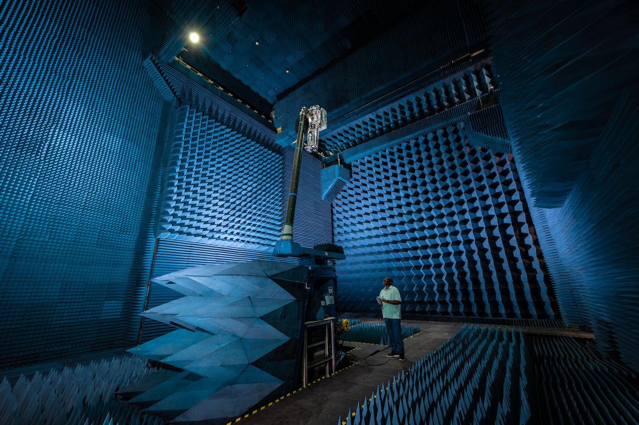
jsc2021e022488 (June 11, 2021) --- NASA’s Exploration Extravehicular Mobility Unit (xEMU) spacesuit undergoes antenna testing in NASA Johnson Space Center’s anechoic chamber to inspect multi-layer insulation keep-out zones for the Wi-Fi and ultra-high-frequency antennas that are part of the spacesuit’s communication system. The xEMU test article is named xGUS, the successor to the Extravehicular Mobility Unit test article (also named GUS), which was named after NASA astronaut Gus Grissom and his iconic silver spacesuit. This image was taken from where the "horn," or source antenna, is located that sends out radio frequency signals to the spacesuit. The anechoic chamber walls are covered with a material that absorbs electromagnetic energy allowing the anechoic chamber to simulate a space environment. The antenna test facility is utilized to test antenna radiation distribution pattern performance for spaceflight applications in electromagnetic environments. Pictured in the photo is antenna test engineer Will Bond.
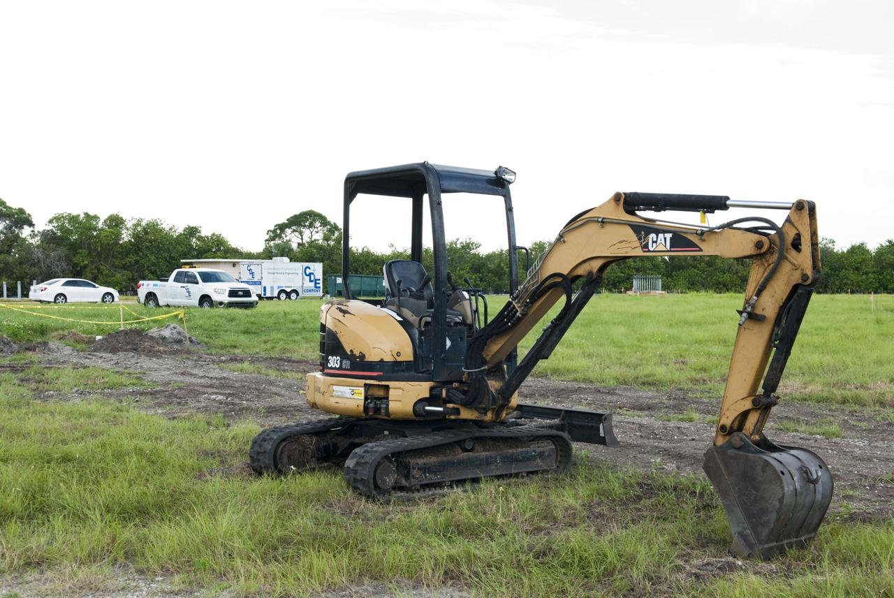
CAPE CANAVERAL, Fla. -- At NASA’s Kennedy Space Center in Florida, groundbreaking will begin for the construction of the Antenna Test Bed Array for the Ka-Band Objects Observation and Monitoring, or Ka-BOOM, system. The construction site is near the former Vertical Processing Facility, which has been demolished. Workers will begin construction on the pile foundations for the 40-foot-diameter dish antenna arrays and their associated utilities, and prepare the site for the operations command center facility. Photo credit: NASA/Charisse Nahser
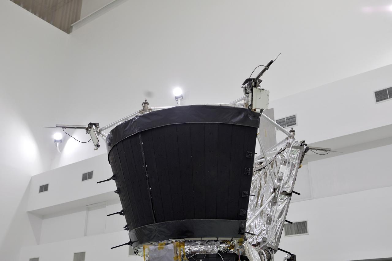
Antenna's on NASA's Parker Solar Probe are deployed for testing at the Astrotech processing facility in Titusville, Florida, near NASA's Kennedy Space Center on Thursday, April 19, 2018. The Parker Solar Probe will launch on a United Launch Alliance Delta IV Heavy rocket from Space Launch Complex 37 at Cape Canaveral Air Force Station in Florida no earlier than Aug. 4, 2018. The mission will perform the closest-ever observations of a star when it travels through the Sun's atmosphere, called the corona. The probe will rely on measurements and imaging to revolutionize our understanding of the corona and the Sun-Earth connection.

Antenna's on NASA's Parker Solar Probe are deployed for testing at the Astrotech processing facility in Titusville, Florida, near NASA's Kennedy Space Center on Thursday, April 19, 2018. The Parker Solar Probe will launch on a United Launch Alliance Delta IV Heavy rocket from Space Launch Complex 37 at Cape Canaveral Air Force Station in Florida no earlier than Aug. 4, 2018. The mission will perform the closest-ever observations of a star when it travels through the Sun's atmosphere, called the corona. The probe will rely on measurements and imaging to revolutionize our understanding of the corona and the Sun-Earth connection.
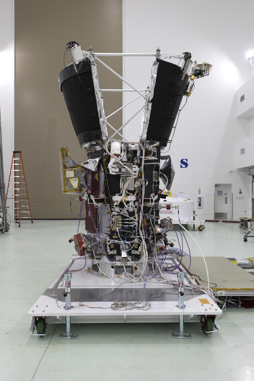
Antenna's on NASA's Parker Solar Probe are deployed for testing at the Astrotech processing facility in Titusville, Florida, near NASA's Kennedy Space Center on Thursday, April 19, 2018. The Parker Solar Probe will launch on a United Launch Alliance Delta IV Heavy rocket from Space Launch Complex 37 at Cape Canaveral Air Force Station in Florida no earlier than Aug. 4, 2018. The mission will perform the closest-ever observations of a star when it travels through the Sun's atmosphere, called the corona. The probe will rely on measurements and imaging to revolutionize our understanding of the corona and the Sun-Earth connection.

Antenna's on NASA's Parker Solar Probe are deployed for testing at the Astrotech processing facility in Titusville, Florida, near NASA's Kennedy Space Center on Thursday, April 19, 2018. The Parker Solar Probe will launch on a United Launch Alliance Delta IV Heavy rocket from Space Launch Complex 37 at Cape Canaveral Air Force Station in Florida no earlier than Aug. 4, 2018. The mission will perform the closest-ever observations of a star when it travels through the Sun's atmosphere, called the corona. The probe will rely on measurements and imaging to revolutionize our understanding of the corona and the Sun-Earth connection.
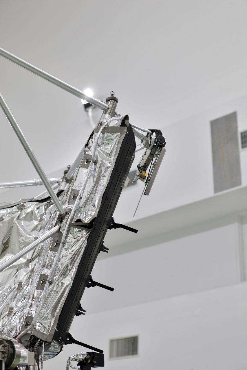
Antenna's on NASA's Parker Solar Probe are deployed for testing at the Astrotech processing facility in Titusville, Florida, near NASA's Kennedy Space Center on Thursday, April 19, 2018. The Parker Solar Probe will launch on a United Launch Alliance Delta IV Heavy rocket from Space Launch Complex 37 at Cape Canaveral Air Force Station in Florida no earlier than Aug. 4, 2018. The mission will perform the closest-ever observations of a star when it travels through the Sun's atmosphere, called the corona. The probe will rely on measurements and imaging to revolutionize our understanding of the corona and the Sun-Earth connection.
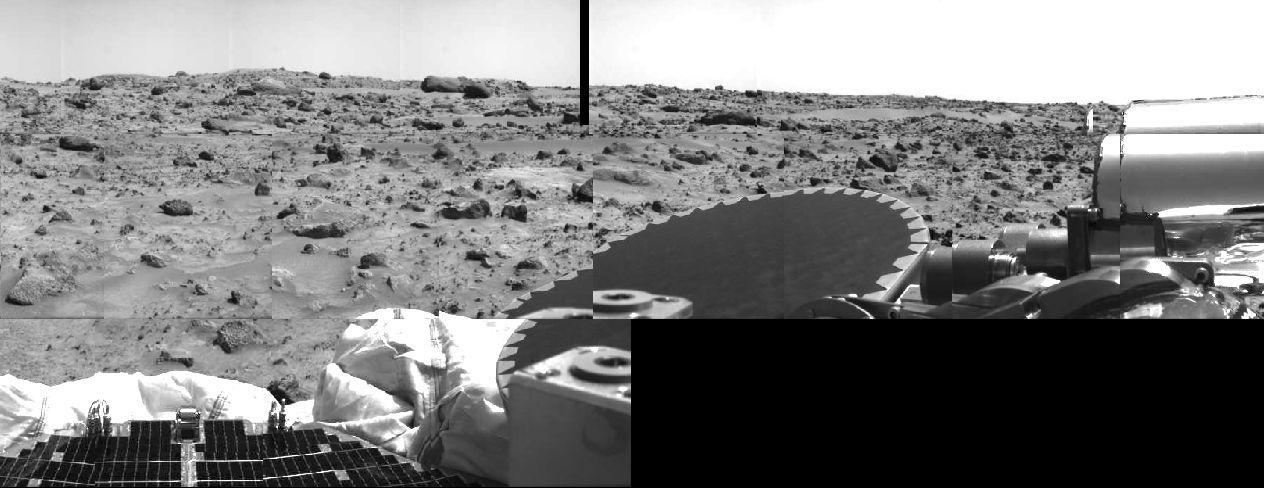
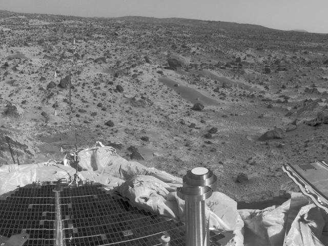
Areas of rocky Martian terrain are seen in this image, taken by the Imager for Mars Pathfinder (IMP) on Sol 2. Portions of a lander petal and deflated airbag are at lower left. The dark disk at center is the high-gain antenna, and the silver cylindrical objects at upper right are part of the antenna's mechanism. An area of relatively smooth terrain is seen at upper right, which may offer clues to how this area was formed, and may be a future target for Sojourner's studies. The black area at lower right and small strip at top center is missing data. http://photojournal.jpl.nasa.gov/catalog/PIA00625