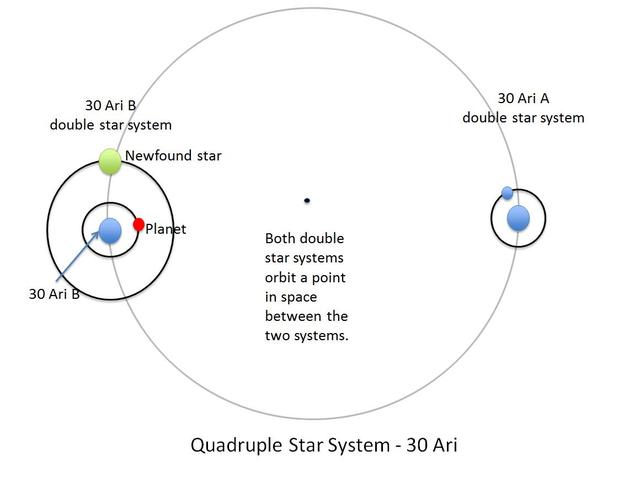
The four stars and one planet of the 30 Ari system are illustrated in this diagram. This quadruple star system consists of two pairs of stars: 30 Ari B and 30 Ari A.
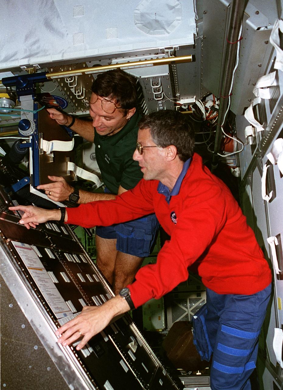
STS079-302-006 (16-26 Sept. 1996) --- Astronauts Jerome (Jay) Apt (right) and Carl E. Walz, both mission specialists, tilt the Active Rack Isolation System (ARIS) hardware which was included on this flight to evaluate conditions and hardware requirements for the International Space Station (ISS). The ARIS is designed to isolate certain experiments from major disturbances that are expected to be found on the ISS, such as vibrations caused by the movement of mechanisms and crew members and the operation of equipment. STS-79 was chosen for the inclusion of the experiment because the Shuttle-Mir complex more closely approximates the acceleration environment of the ISS.
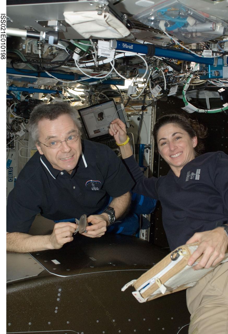
ISS021-E-010198 (19 Oct. 2009) --- Canadian Space Agency astronaut Robert Thirsk and NASA astronaut Nicole Stott, both Expedition 21 flight engineers, install the Active Rack Isolation System (ARIS) hardware on the Fluids Integrated Rack (FIR) in the Destiny laboratory of the International Space Station.

This artist conception shows the 30 Ari system, which includes four stars and a planet. The planet, a gas giant, orbits its primary star yellow in about a year time.
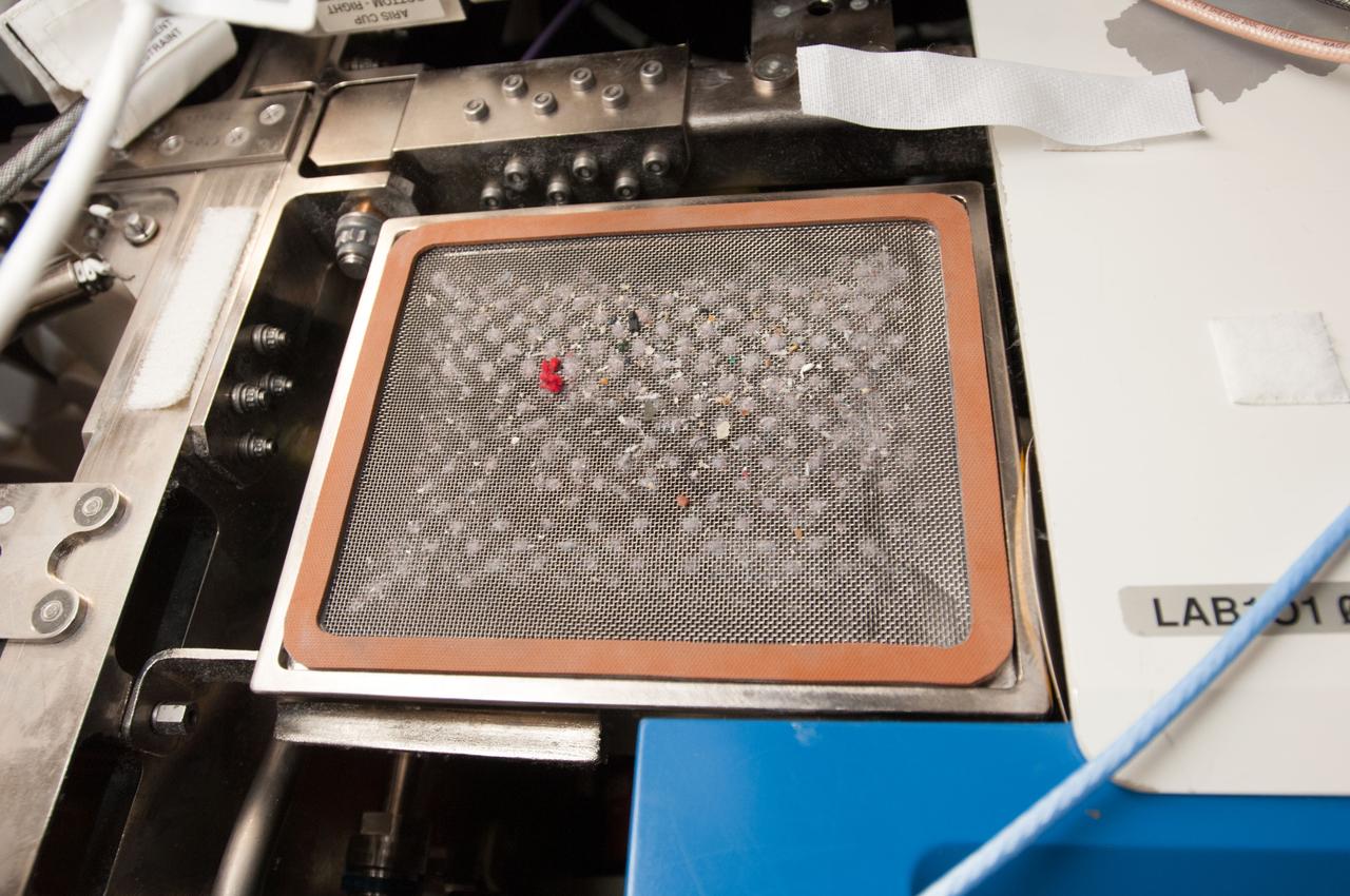
View of filter during cleaning on the Active Rack Isolation System (ARIS). Photo was taken during Expedition 34.
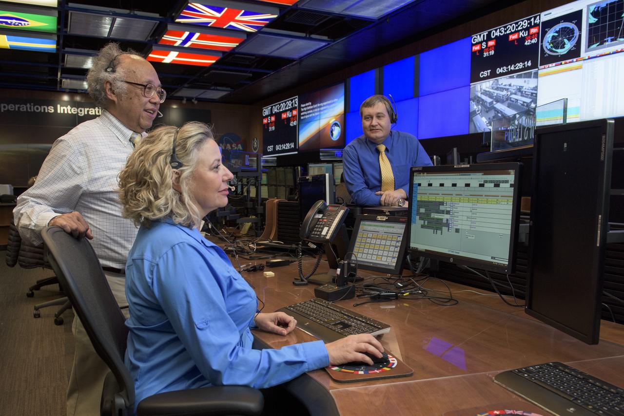
A PHOTOGRAPH FIRST RUN IN THE “MARSHALL STAR” IN 2001 IS RECREATED FOR PUBLICATION 15 YEARS LATER IN THE REMODELED PAYLOAD OPERATIONS INTEGRATION CENTER (POIC). PICTURED (L TO R) ARE: BRIAN LITTLE, OLA MYSZKA, AND ARIS TANONE.
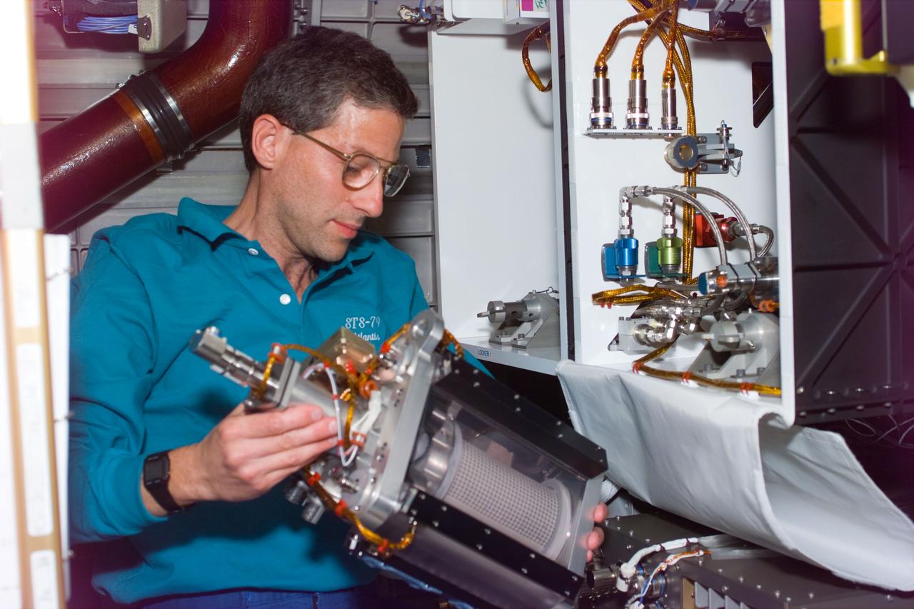
STS79-E-5042 (18 September 1996) --- Astronaut Jerome (Jay) Apt performs In-Flight Maintenance (IFM) on Active Rack Isolation System (ARIS) experiment, on Flight Day 3.
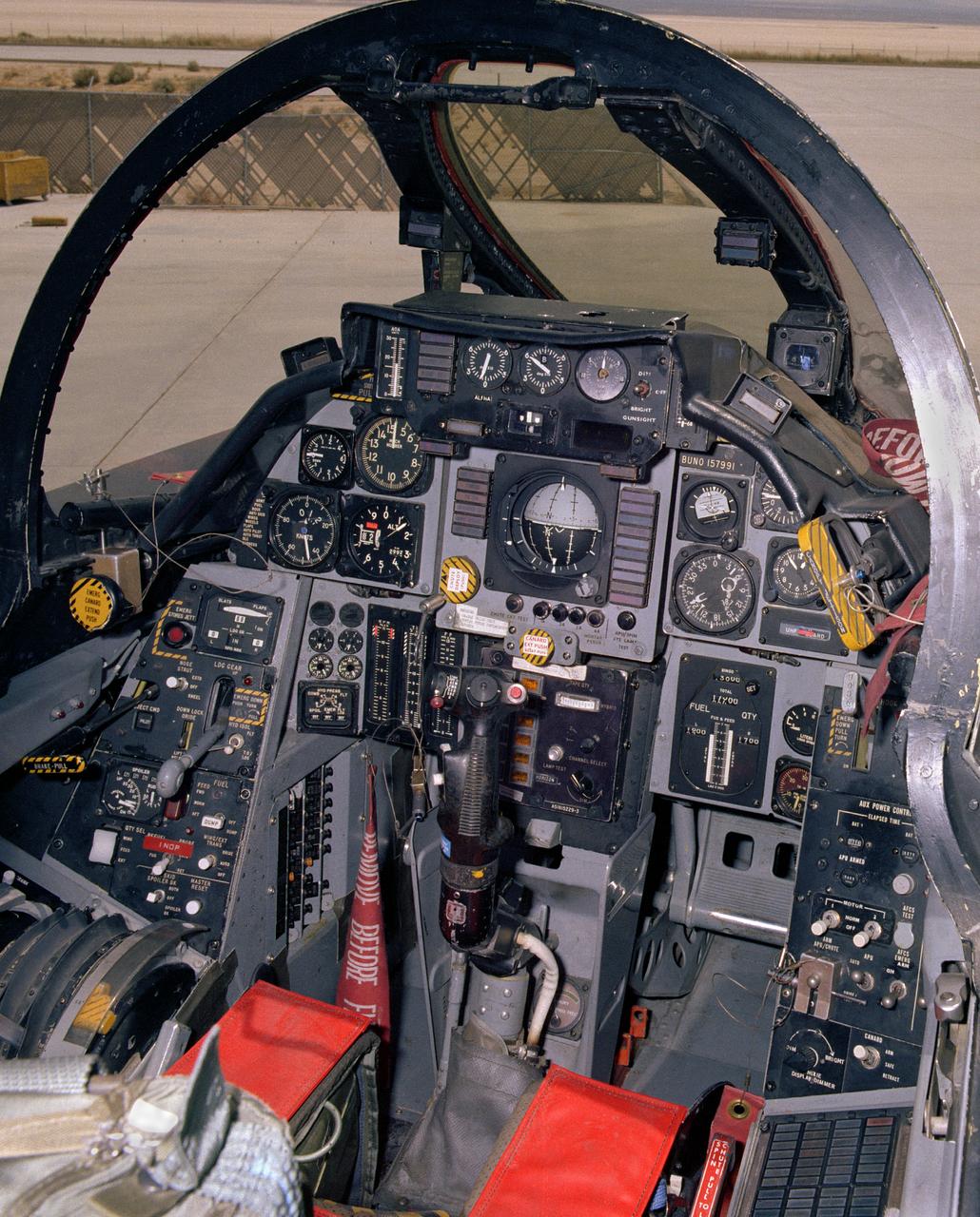
View of the cockpit of NASA's F-14, tail number 991. This aircraft was the first of a series of post-Vietnam fighters, followed by the F-15, F-16, and F-18. They were designed for maneuverability in air-to-air combat. The F-14s had a spin problem that posed problems for its ability to engage successfully in a dogfight, since it tended to depart from controlled flight at the high angles of attack that frequently occur in close-in engagements.

CAPE CANAVERAL, Fla. – Representatives from the European Space Agency, or ESA, toured the Operations and Checkout Building high bay and viewed the Orion crew module at NASA’s Kennedy Space Center in Florida. From the left, are Philippe Deloo, ESA European Service Module Study manager Kathleen Schubert, NASA crew and service module deputy manager Bernardo Patti, ESA manager of International Space Station Operations Mark Geyer, NASA Orion program manager and Ari Blum, NASA export administrator at Johnson Space Center in Houston. Orion is the exploration spacecraft designed to carry crews to space beyond low Earth orbit. It will provide emergency abort capability, sustain the crew during the space travel and provide safe re-entry from deep space return velocities. Orion’s first unpiloted test flight is scheduled to launch in 2014 atop a Delta IV rocket. A second uncrewed flight test is scheduled for 2017 on NASA’s Space Launch System rocket. For more information, visit http://www.nasa.gov/orion. Photo credit: NASA/Jim Grossmann
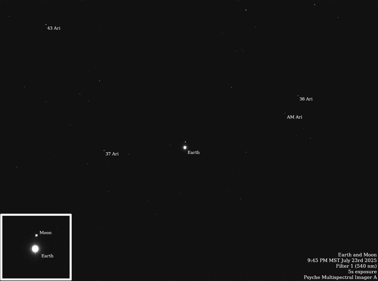
NASA's Psyche spacecraft captured images of Earth and our Moon from about 180 million miles (290 kilometers) away in July 2025. The images were obtained during one of the mission team's periodic maintenance and calibration tests for the twin cameras that make up the imager instrument. Scientists on the imaging team, led by Arizona State University, captured multiple long-exposure (up to 10-second) pictures of the two bodies, which appear as dots sparkling with reflected sunlight amid a starfield in the constellation Aries. The observations help the team determine how the cameras respond to solar system objects that shine by reflected sunlight, just like the Psyche asteroid. In January 2025, Psyche captured an image that included Mars, Jupiter, and the Jovian moons Io, Ganymede, Callisto, and Europa. The image here was captured by Psyche's primary camera, Imager A, on July 23. The Psyche mission is led by ASU. Lindy Elkins-Tanton of the University of California, Berkeley is the principal investigator. A division of Caltech in Pasadena, JPL is responsible for the mission's overall management, system engineering, integration and test, and mission operations. Maxar Technologies in Palo Alto, California, provided the high-power solar electric propulsion spacecraft chassis. ASU leads the operations of the imager instrument, working in collaboration with Malin Space Science Systems in San Diego on the design, fabrication, and testing of the cameras. https://photojournal.jpl.nasa.gov/catalog/PIA26569

KENNEDY SPACE CENTER, FLA. -- With the ribbon-cutting ceremony, the new Operations Support Building II is officially in business. Participating in the event are (left to right) Aris Garcia, vice president of the architecture firm Wolfgang Alvarez; Mark Nappi, associate program manager of Ground Operations for United Space Alliance; Donald Minderman, NASA project manager; Scott Kerr, director of Engineering Development at Kennedy; Bill Parsons, deputy director of Kennedy Space Center; Miguel Morales, with NASA Engineering Development; Mike Wetmore, director of Shuttle Processing; and Tim Clancy, president of the construction firm Clancy & Theys. The Operations Support Building II is an Agency safety and health initiative project to replace 198,466 square feet of substandard modular housing and trailers in the Launch Complex 39 area at Kennedy Space Center. The five-story building, which sits south of the Vehicle Assembly Building and faces the launch pads, includes 960 office spaces, 16 training rooms, computer and multimedia conference rooms, a Mission Conference Center with an observation deck, technical libraries, an Exchange store, storage, break areas, and parking. Photo credit: NASA/George Shelton

A model of the new Aries I crew launch vehicle, for which NASA is designing, testing and evaluating hardware and related systems, is seen here on display at the Marshall Space Fight Center (MSFC), in Huntsville, Alabama. The Ares I crew launch vehicle is the rocket that will carry a new generation of space explorers into orbit. Under the goals of the Vision for Space Exploration, Ares I is a chief component of the cost-effective space transportation infrastructure being developed by NASA’s Constellation Program. These transportation systems will safely and reliably carry human explorers back to the moon, and then onward to Mars and other destinations in the solar system. The Ares I effort includes multiple project element teams at NASA centers and contract organizations around the nation, and is led by the Exploration Launch Projects Office at NASA’s MFSC. Together, these teams are developing vehicle hardware, evolving proven technologies, and testing components and systems. Their work builds on powerful, reliable space shuttle propulsion elements and nearly a half-century of NASA space flight experience and technological advances. Ares I is an inline, two-stage rocket configuration topped by the Crew Exploration Vehicle, its service module and a launch abort system. The launch vehicle’s first stage is a single, five-segment reusable solid rocket booster derived from the Space Shuttle Program’s reusable solid rocket motor that burns a specially formulated and shaped solid propellant called polybutadiene acrylonitrile (PBAN). The second or upper stage will be propelled by a J-2X main engine fueled with liquid oxygen and liquid hydrogen. In addition to its primary mission of carrying crews of four to six astronauts to Earth orbit, the launch vehicle’s 25-ton payload capacity might be used for delivering cargo to space, bringing resources and supplies to the International Space Station or dropping payloads off in orbit for retrieval and transport to exploration teams on the moon. Crew transportation to the space station is planned to begin no later than 2014. The first lunar excursion is scheduled for the 2020 timeframe.
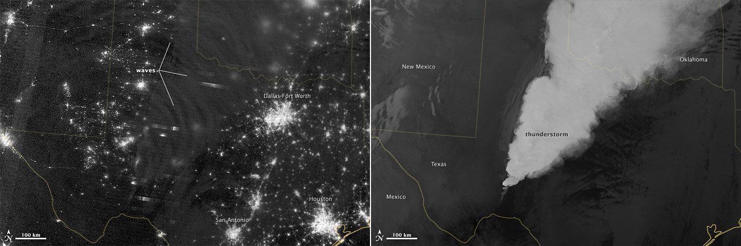
In April 2012, waves in Earth’s “airglow” spread across the nighttime skies of northern Texas like ripples in a pond. In this case, the waves were provoked by a massive thunderstorm. Airglow is a layer of nighttime light emissions caused by chemical reactions high in Earth’s atmosphere. A variety of reactions involving oxygen, sodium, ozone and nitrogen result in the production of a very faint amount of light. In fact, it’s approximately one billion times fainter than sunlight (~10-11 to 10-9 W·cm-2· sr-1). This chemiluminescence is similar to the chemical reactions that light up a glow stick or glow-in-the-dark silly putty. The “day-night band,” of the Visible Infrared Imaging Radiometer Suite (VIIRS) on the Suomi NPP satellite captured these glowing ripples in the night sky on April 15, 2012 (top image). The day-night band detects lights over a range of wavelengths from green to near-infrared and uses highly sensitive electronics to observe low light signals. (The absolute minimum signals detectable are at the levels of nightglow emission.) The lower image shows the thunderstorm as observed by a thermal infrared band on VIIRS. This thermal band, which is sensitive only to heat emissions (cold clouds appear white), is not sensitive to the subtle visible-light wave structures seen by the day-night band. Technically speaking, airglow occurs at all times. During the day it is called “dayglow,” at twilight “twilightglow,” and at night “nightglow.” There are slightly different processes taking place in each case, but in the image above the source of light is nightglow. The strongest nightglow emissions are mostly constrained to a relatively thin layer of atmosphere between 85 and 95 kilometers (53 and 60 miles) above the Earth’s surface. Little emission occurs below this layer since there’s a higher concentration of molecules, allowing for dissipation of chemical energy via collisions rather than light production. Likewise, little emission occurs above that layer because the atmospheric density is so tenuous that there are too few light-emitting reactions to yield an appreciable amount of light. Suomi NPP is in orbit around Earth at 834 kilometers (about 518 miles), well above the nightglow layer. The day-night band imagery therefore contains signals from the direction upward emission of the nightglow layer and the reflection of the downward nightglow emissions by clouds and the Earth’s surface. The presence of these nightglow waves is a graphic visualization of the usually unseen energy transfer processes that occur continuously between the lower and upper atmosphere. While nightglow is a well-known phenomenon, it’s not typically considered by Earth-viewing meteorological sensors. In fact, scientists were surprised at Suomi NPP’s ability to detect it. During the satellite’s check-out procedure, this unanticipated source of visible light was thought to indicate a problem with the sensor until scientists realized that what they were seeing was the faintest of light in the darkness of night. NASA Earth Observatory image by Jesse Allen and Robert Simmon, using VIIRS Day-Night Band data from the Suomi National Polar-orbiting Partnership. Suomi NPP is the result of a partnership between NASA, the National Oceanic and Atmospheric Administration, and the Department of Defense. Caption by Aries Keck and Steve Miller. Instrument: Suomi NPP - VIIRS Credit: <b><a href="http://www.earthobservatory.nasa.gov/" rel="nofollow"> NASA Earth Observatory</a></b> <b>Click here to view all of the <a href="http://earthobservatory.nasa.gov/Features/NightLights/" rel="nofollow"> Earth at Night 2012 images </a></b> <b>Click here to <a href="http://earthobservatory.nasa.gov/NaturalHazards/view.php?id=79817" rel="nofollow"> read more </a> about this image </b> <b><a href="http://www.nasa.gov/audience/formedia/features/MP_Photo_Guidelines.html" rel="nofollow">NASA image use policy.</a></b> <b><a href="http://www.nasa.gov/centers/goddard/home/index.html" rel="nofollow">NASA Goddard Space</a></b>