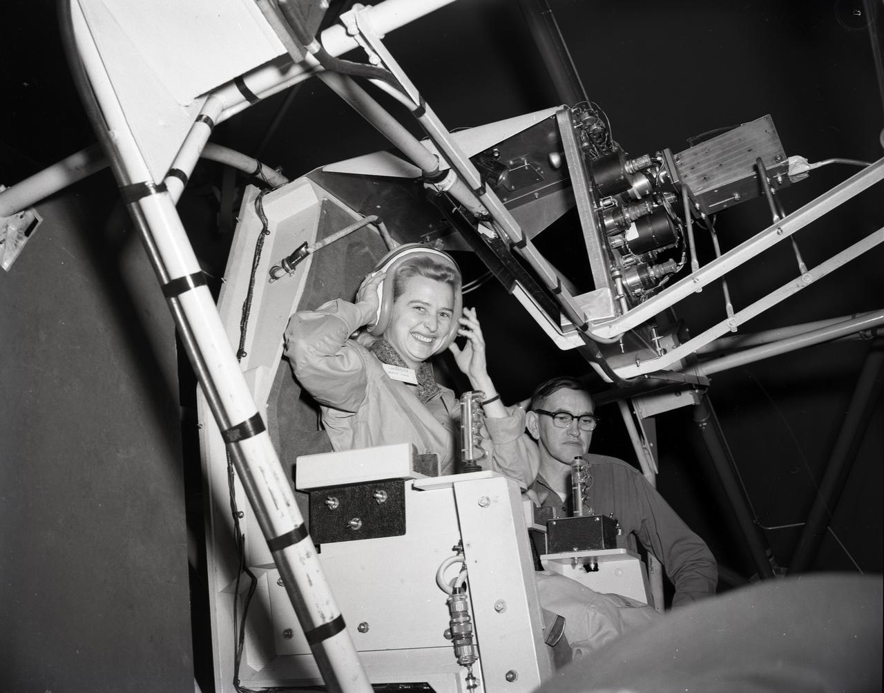
JERRIE COBB - PILOT - TESTING GIMBAL RIG IN THE ALTITUDE WIND TUNNEL, AWT
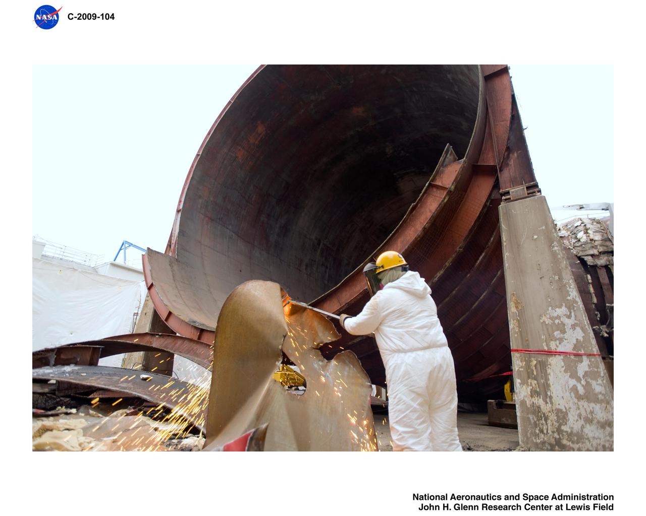
Altitude Wind Tunnel (AWT) construction: cutting tunnel
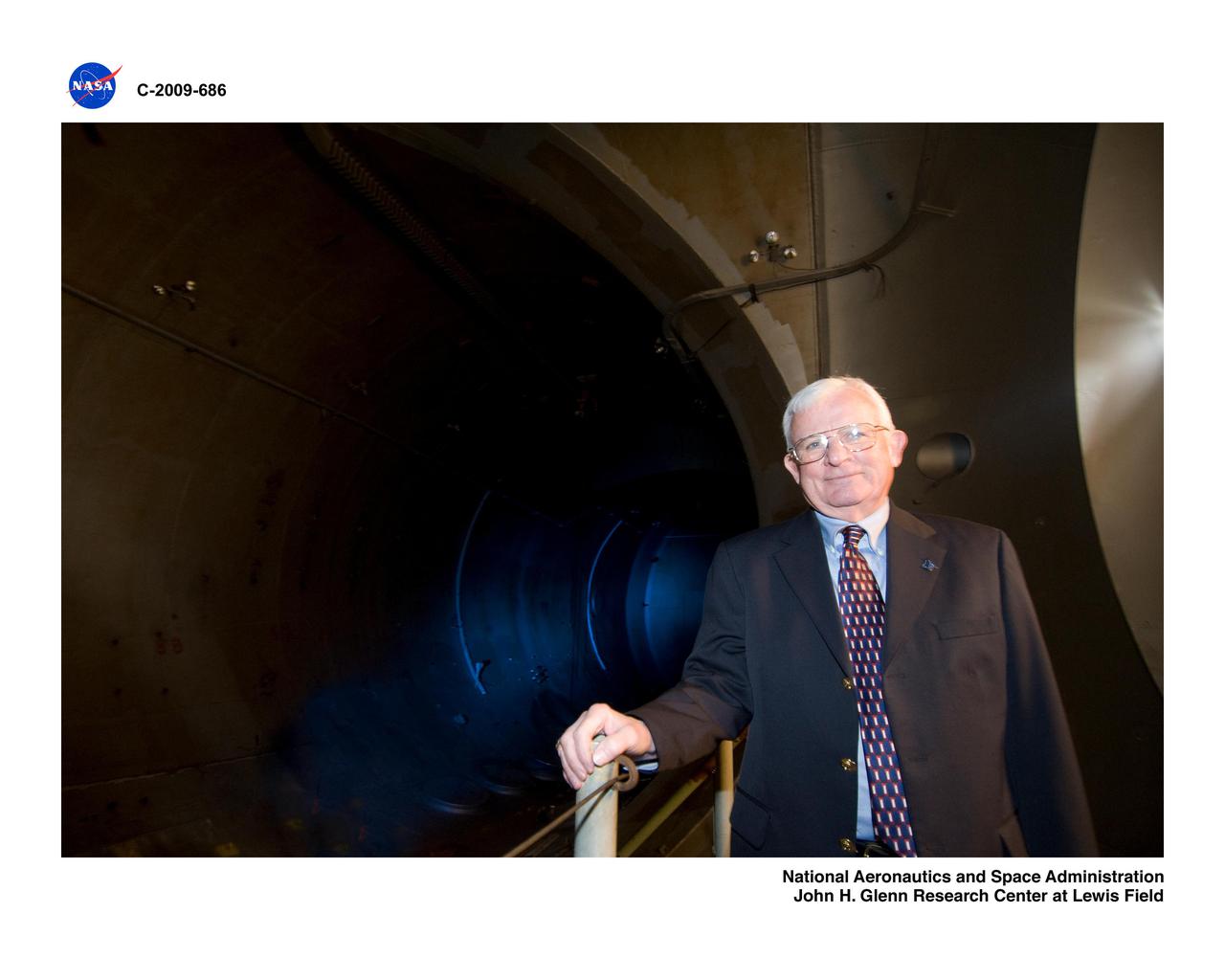
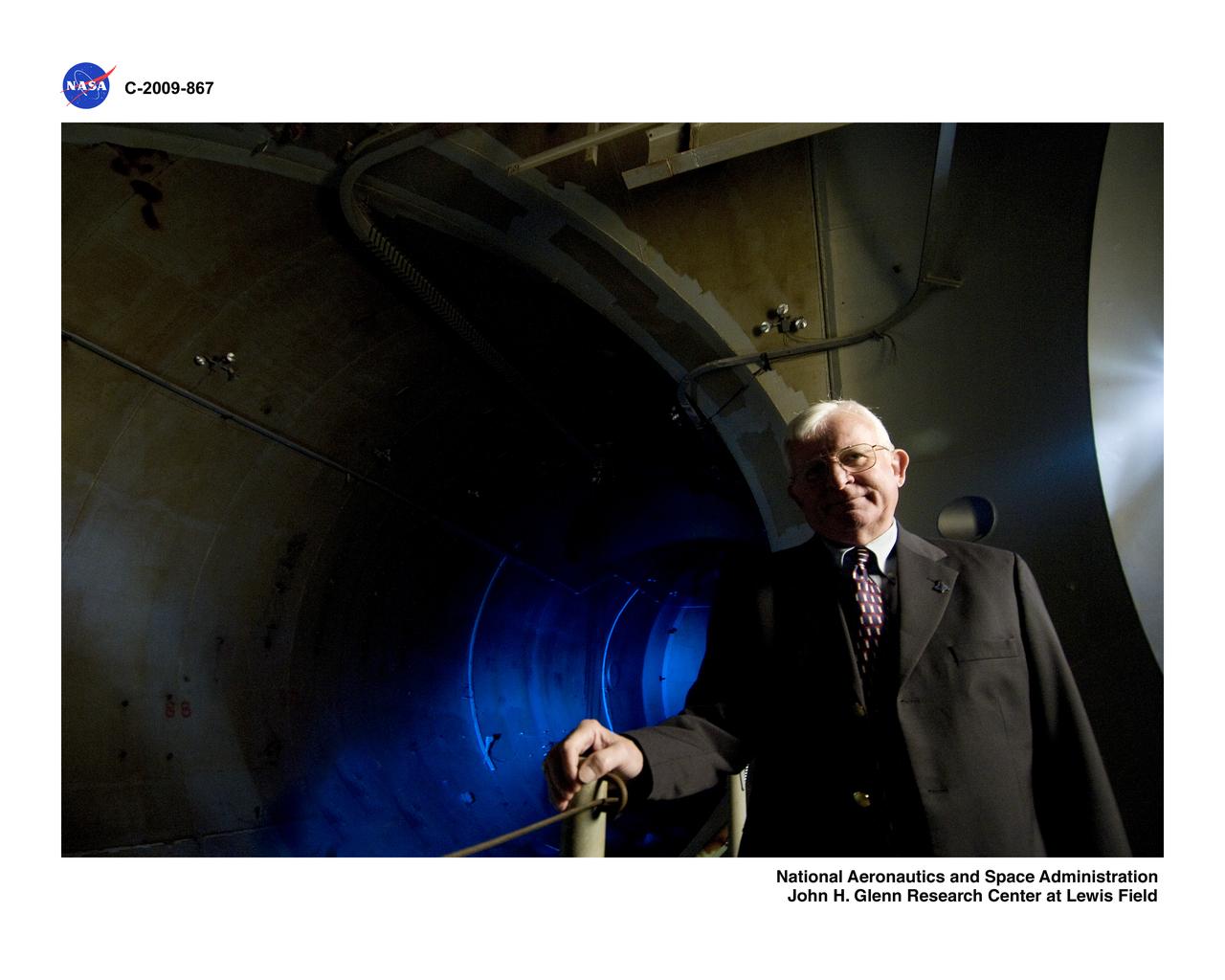
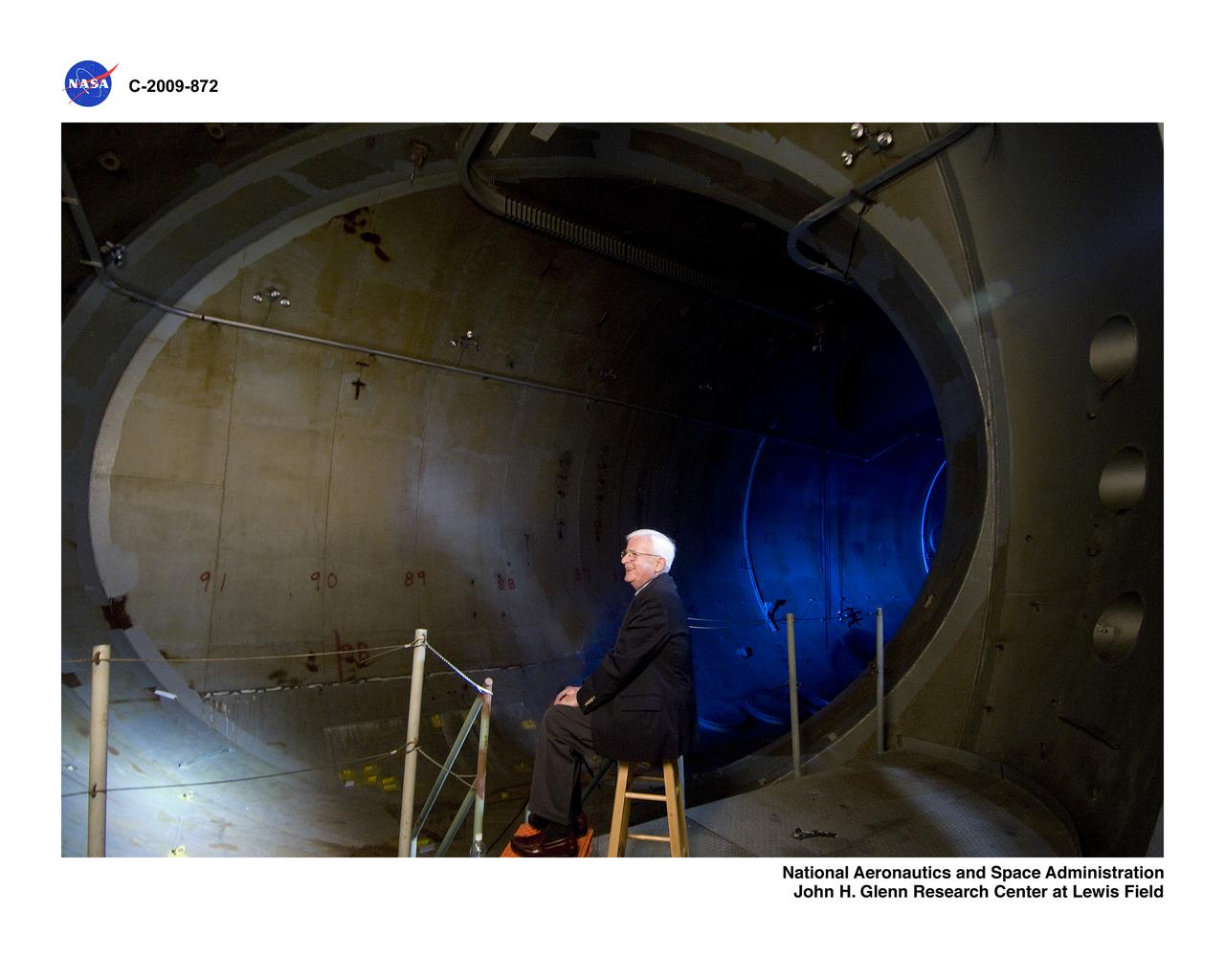
Former Center Director, Larry Ross, in the Altitude Wind Tunnel, AWT
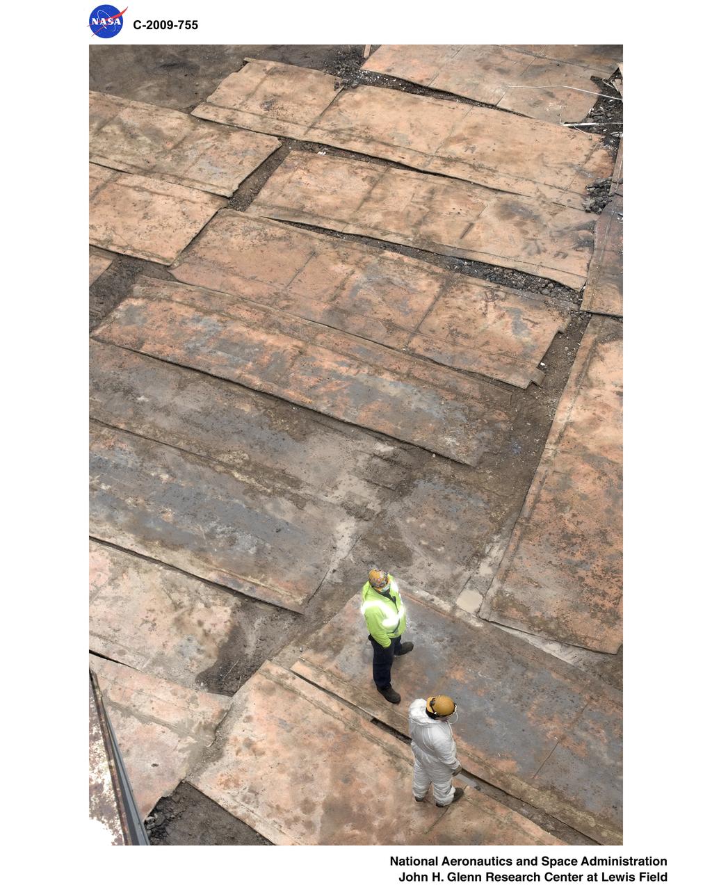
Altitude Wind Tunnel (AWT) Demolition
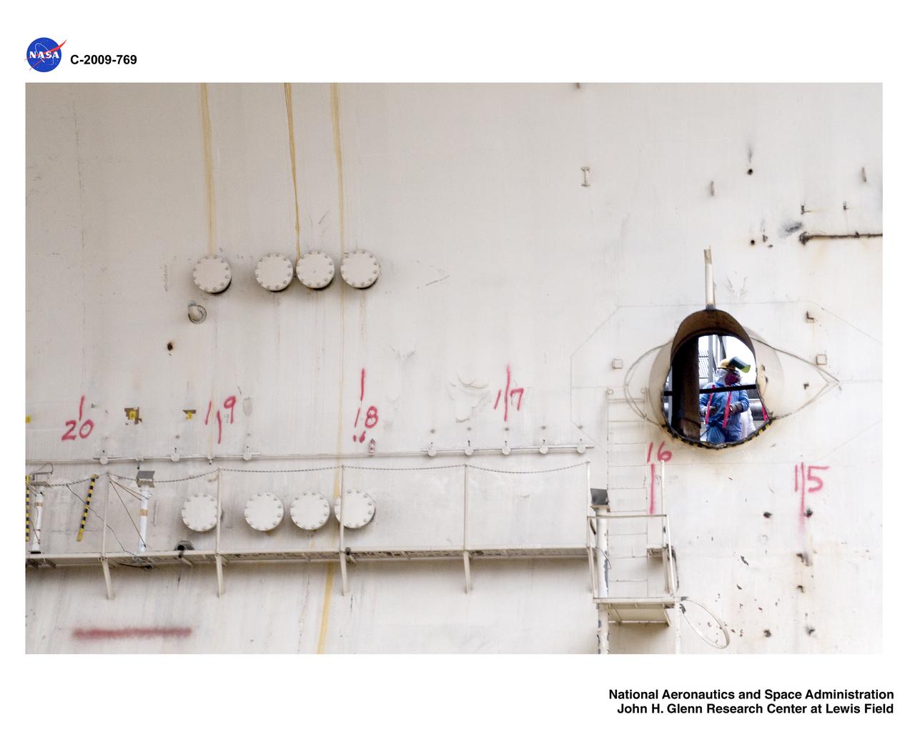
Altitude Wind Tunnel (AWT) Demolition
Altitude Wind Tunnel (AWT) Interviews
Altitude Wind Tunnel (AWT) Interviews

Altitude Wind Tunnel (AWT) construction: cutting tunnel
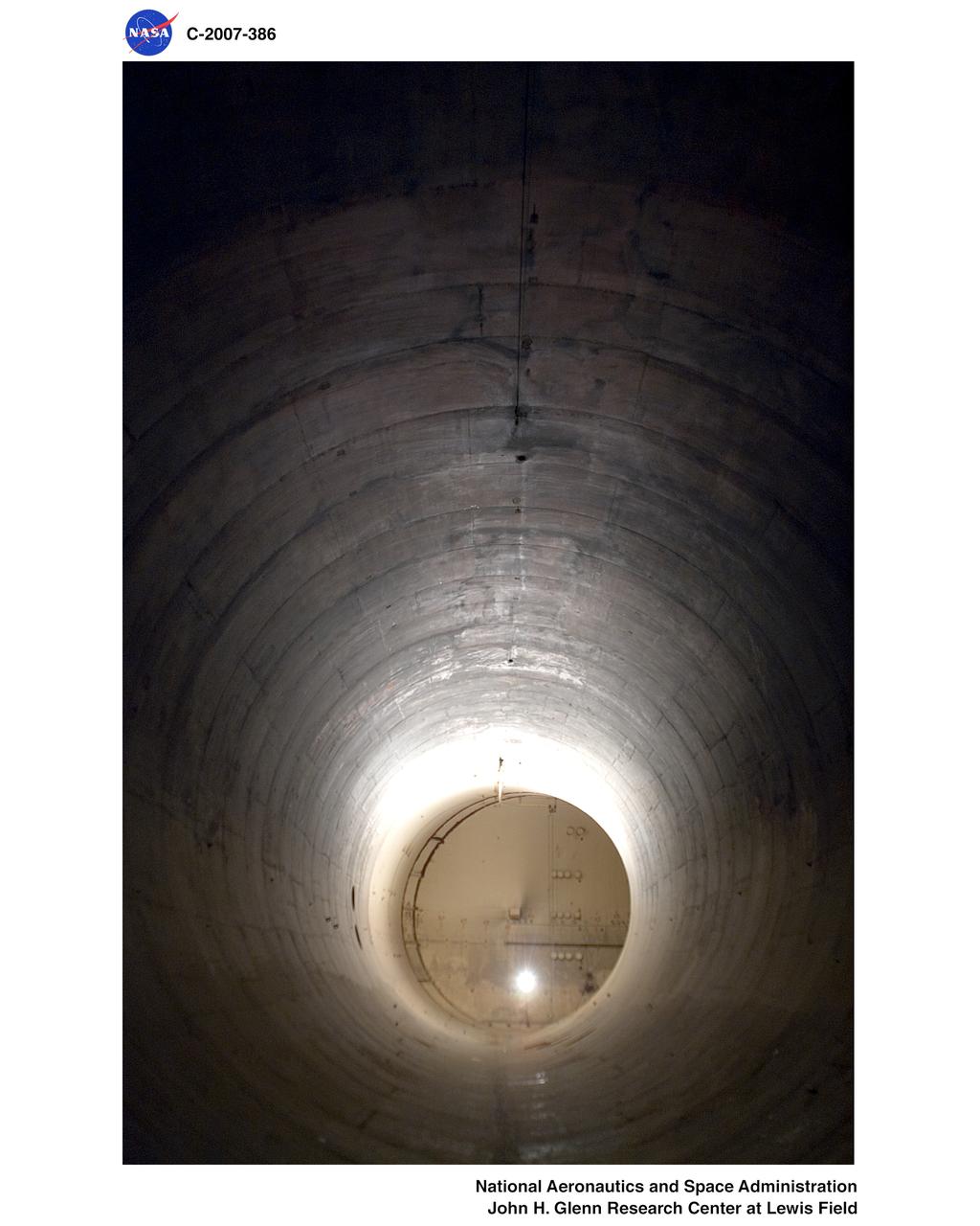
Altitude Wind Tunnel (AWT) interior pictures before demolition
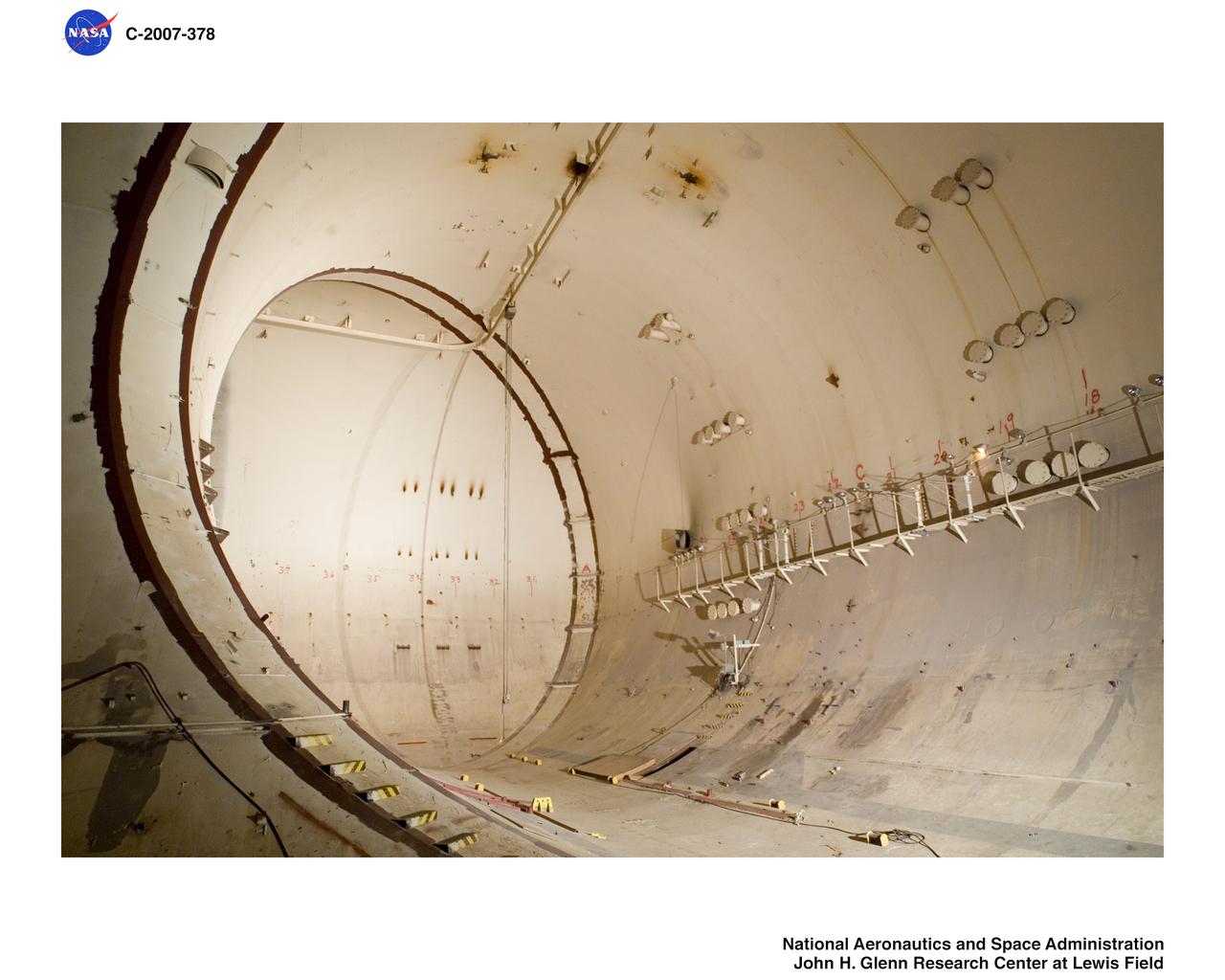
Altitude Wind Tunnel (AWT) interior pictures before demolition
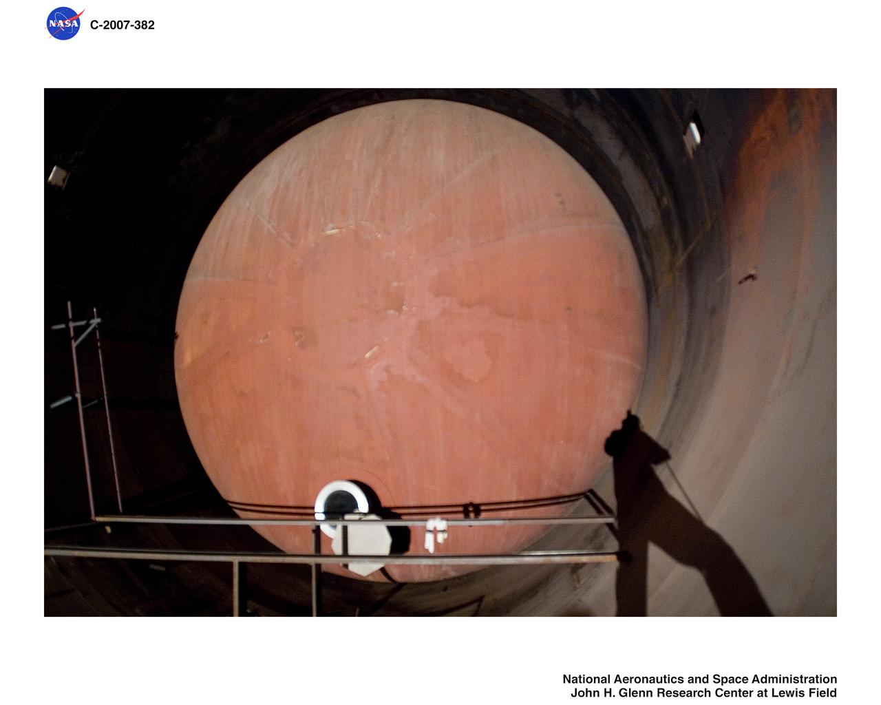
Altitude Wind Tunnel (AWT) interior pictures before demolition
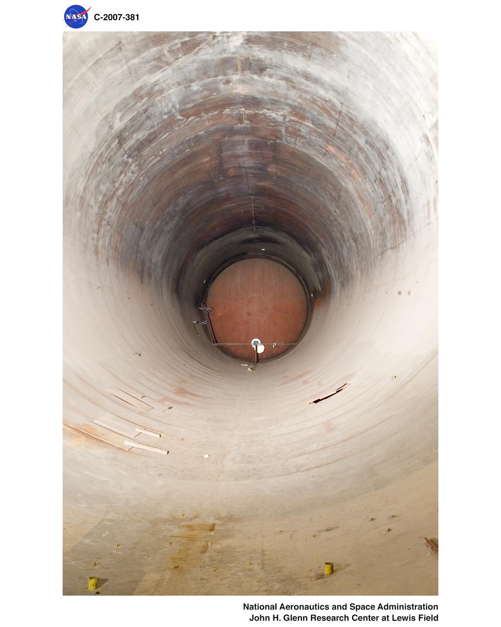
Altitude Wind Tunnel (AWT) interior pictures before demolition
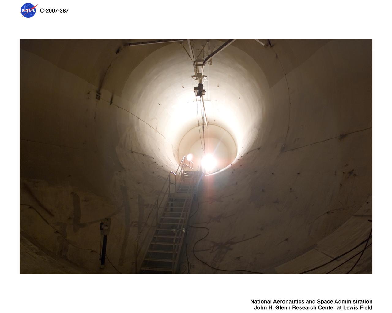
Altitude Wind Tunnel (AWT) interior pictures before demolition
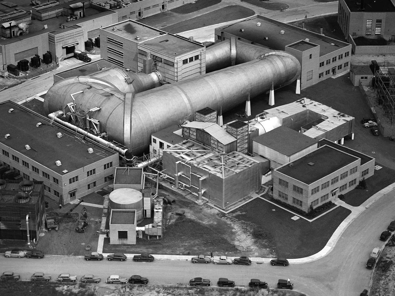
This aerial photograph shows the entire original wind tunnel complex at the National Advisory Committee for Aeronautics (NACA) Aircraft Engine Research Laboratory. The large Altitude Wind Tunnel (AWT) at the center of the photograph dominates the area. The Icing Research Tunnel to the right was incorporated into the lab’s design to take advantage of the AWT’s powerful infrastructure. The laboratory’s first supersonic wind tunnel was added to this complex just prior to this September 1945 photograph. The AWT was the nation’s only wind tunnel capable of studying full-scale engines in simulated flight conditions. The AWT’s test section and control room were within the two-story building near the top of the photograph. The exhauster equipment used to thin the airflow and the drive motor for the fan were in the building to the right of the tunnel. The unique refrigeration equipment was housed in the structure to the left of the tunnel. The Icing Research Tunnel was an atmospheric tunnel that used the AWT’s refrigeration equipment to simulate freezing rain inside its test section. A spray bar system inside the tunnel was originally used to create the droplets. The 18- by 18-inch supersonic wind tunnel was built in the summer of 1945 to take advantage of the AWT’s powerful exhaust system. It was the lab’s first supersonic tunnel and could reach Mach 1.91. Eventually the building would house three small supersonic tunnels, referred to as the “stack tunnels” because of the vertical alignment. The two other tunnels were added to this structure in 1949 and 1951.
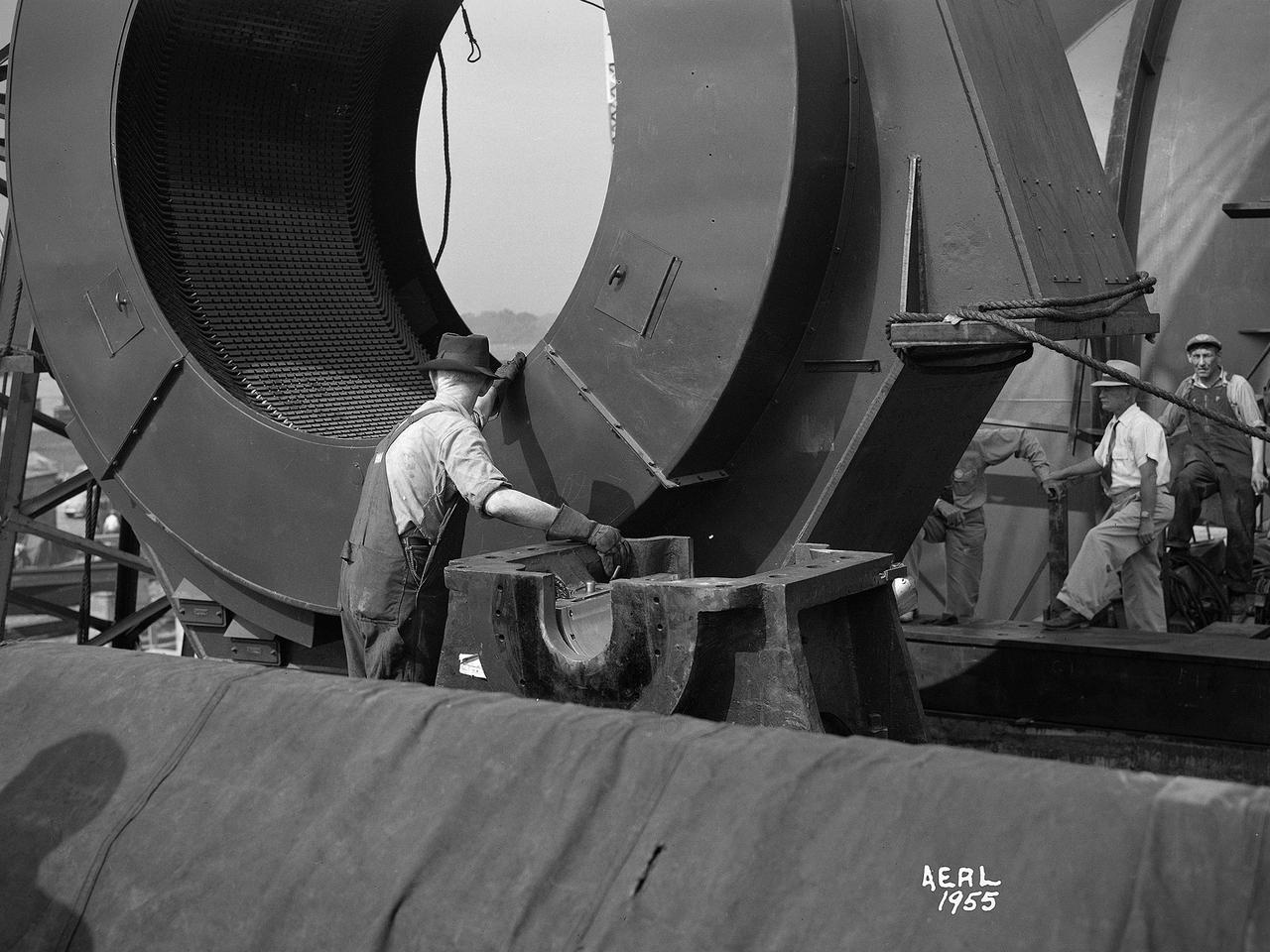
Construction workers install the drive motor for the Altitude Wind Tunnel (AWT) in the Exhauster Building at the National Advisory Committee for Aeronautics (NACA) Aircraft Engine Research Laboratory. The AWT was capable of operating full-scale engines in air density, speed, and temperature similar to that found at high altitudes. The tunnel could produce wind speeds up to 500 miles per hour through a 20-foot-diameter test section at the standard operating altitude of 30,000 feet. The airflow was created by a large wooden fan near the tunnel’s southeast corner. This photograph shows the installation of the 18,000-horsepower drive motor inside the adjoining Exhauster Building in July 1943. The General Electric motor, whose support frame is seen in this photograph, connected to a drive shaft that extended from the building, through the tunnel shell, and into a 12-bladed, 31-foot-diameter spruce wood fan. Flexible couplings on the shaft allowed for the movement of the shell. The corner of the Exhauster Building was built around the motor after its installation. The General Electric induction motor could produce 10 to 410 revolutions per minute and create wind speeds up to 500 miles per hour, or Mach 0.63, at 30,000 feet. The AWT became operational in January 1944 and tested piston, turbojet and ramjet engines for nearly 20 years.
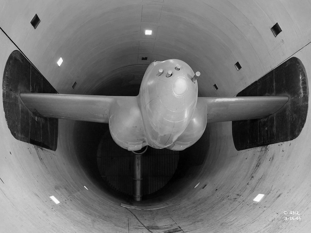
The Altitude Wind Tunnel (AWT) was the National Advisory Committee for Aeronautics (NACA) Aircraft Engine Research Laboratory’s largest and most important test facility in the 1940s. The AWT employed massive cooling and exhaust systems to simulate conditions found at high altitudes. The facility was originally designed to test large piston engines in a simulated flight environment. The introduction of the turbojet during the tunnel’s construction, however, changed the facility’s focus before it became operational. Its first test program was a study of the Bell YP–59A Airacomet and its General Electric I–16 turbojets. The Airacomet was the United States’ first attempt to build a jet aircraft. 1600-horsepower centrifugal engines based on an early design by British engineer Frank Whittle were incorporated into an existing Bell airframe. In October 1942 the Airacomet was secretly test flown in the California desert. The aircraft’s performance was limited, however, and the NACA was asked to study the engines in the AWT. The wind tunnel’s 20-foot-diameter test section was large enough to accommodate entire aircraft with its wing tips and tail removed. The I-16 engines were studied exhaustively in early 1944. They first analyzed the engines in their original configuration and then implemented a boundary layer removal duct, a new nacelle inlet, and new cooling seals. Tests of the modified version showed that the improved distribution of airflow increased the I–16’s performance by 25 percent. The Airacomet never overcame some of its inherent design issues, but the AWT went on to study nearly every emerging US turbojet model during the next decade.
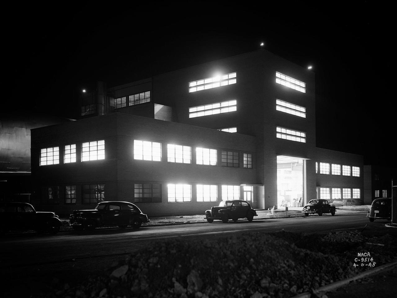
The Altitude Wind Tunnel (AWT) during one of its overnight runs at the National Advisory Committee for Aeronautics (NACA) Aircraft Engine Research Laboratory in Cleveland, Ohio. The AWT was run during night hours so that its massive power loads were handled when regional electric demands were lowest. At the time the AWT was among the most complex wind tunnels ever designed. In order to simulate conditions at high altitudes, NACA engineers designed innovative new systems that required tremendous amounts of electricity. The NACA had an agreement with the local electric company that it would run its larger facilities overnight when local demand was at its lowest. In return the utility discounted its rates for the NACA during those hours. The AWT could produce wind speeds up to 500 miles per hour through its 20-foot-diameter test section at the standard operating altitude of 30,000 feet. The airflow was created by a large fan that was driven by an 18,000-horsepower General Electric induction motor. The altitude simulation was accomplished by large exhauster and refrigeration systems. The cold temperatures were created by 14 Carrier compressors and the thin atmosphere by four 1750-horsepower exhausters. The first and second shifts usually set up and broke down the test articles, while the third shift ran the actual tests. Engineers would often have to work all day, then operate the tunnel overnight, and analyze the data the next day. The night crew usually briefed the dayshift on the tests during morning staff meetings.
The secret test of the Bell YP–59A Airacomet in the spring of 1944 was the first investigation in the National Advisory Committee for Aeronautics (NACA) Aircraft Engine Research Laboratory’s new Altitude Wind Tunnel (AWT). The Airacomet, powered by two General Electric I–A centrifugal turbojets, was the first US jet aircraft. The Airacomet’s 290-miles per hour speed, however, was dwarfed by the German Messerschmitt Me-262 Schwalbe’s 540 miles per hour. In 1941 and 1942 General Electric built the first US jet engines based on technical drawings from British engineer Frank Whittle. Bell Aircraft was contracted to produce an airframe to incorporate the new engines. The result was the Bell XP–59A Airacomet. The aircraft made its first flight over Muroc Lake, California, on October 2, 1942. The aircraft continued to struggle over the next year and the NACA was asked to test it in the new AWT. A Bell YP–59A was flown from the Bell plant in Buffalo to Cleveland by Bob Stanley, who had piloted the first successful flight of the XP–59A at Muroc in 1942. The wing tips and tail were cut from the aircraft so that it would fit into the AWT’s test section. The study first analyzed the engines in their original configuration and then implemented a boundary layer removal duct, a new nacelle inlet, and new cooling seals. Tests of the modified version showed that the improved airflow distribution increased the I–16’s performance by 25 percent. Despite the improved speed, the aircraft was not stable enough to be used in combat, and the design was soon abandoned.
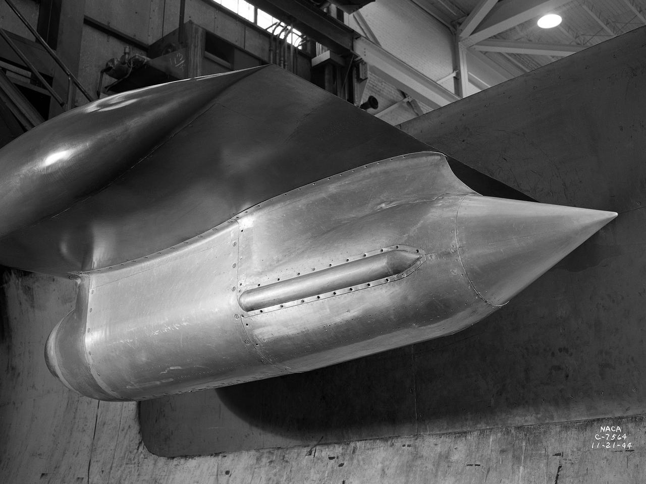
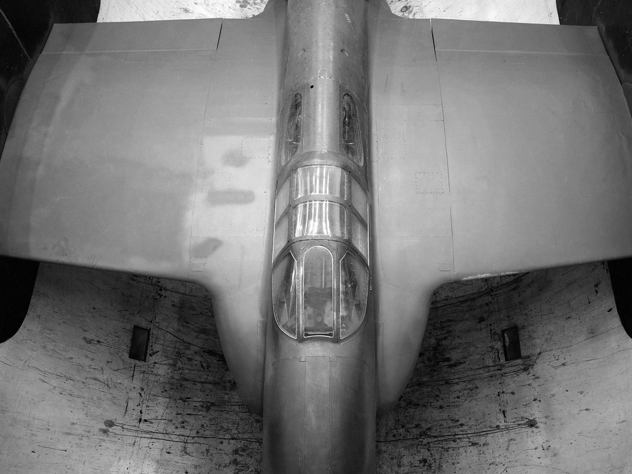
The Westinghouse 19XB turbojet seen from the side in the Altitude Wind Tunnel (AWT) test section at the National Advisory Committee for Aeronautics (NACA) Aircraft Engine Research Laboratory. Westinghouse started the development of a series of relatively small axial-flow turbojets for the Navy shortly after Pearl Harbor. In 1943 the 19A engine became both the first operational US-designed jet engine and the only U.S. turbojet incorporated into an aircraft during the war in Europe. In March 1943 Westinghouse agreed to create an improved six-stage 1400-pound thrust version, the 19B. The engine underwent its first test run a year later in March 1944. Almost immediately the navy agreed to Westinghouse’s proposal for the even larger 10-stage, 1600-pound-thrust 19XB prototype. By July 1944 the navy had contracted with the NACA for the testing of both engines in the AWT. The tunnel was the nation’s only facility for studying full-scale engines in simulated altitude conditions. The wind tunnel investigations, which began on September 9, 1944, revealed the superiority of the previously untested 19XB over the 19B. The 19B engines failed to restart consistently and suffered combustion blowouts above 17,000 feet. The 19XB, however, performed well and restarted routinely at twice that altitude. Two months later on January 26, 1945, two 19Bs powered a McDonnell XFD–1 Phantom, the US Navy’s first fighter jet, on its initial flight. Following its exceptional performance in the AWT, the 19XB engines soon replaced the 19Bs in the Phantom.
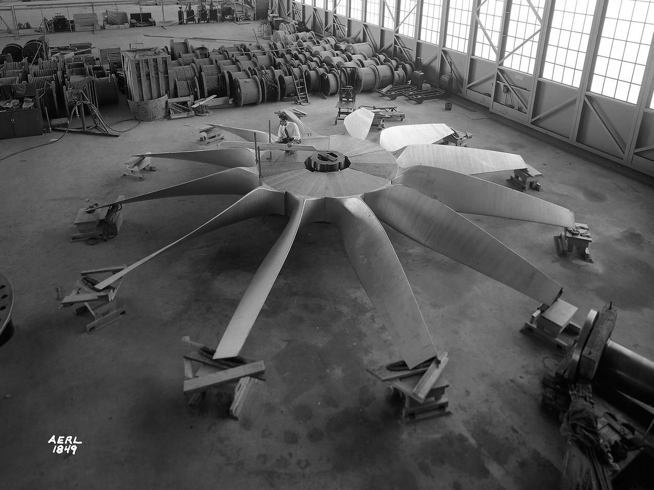
National Advisory Committee for Aeronautics (NACA) engineers assembled the Altitude Wind Tunnel’s (AWT) large wooden drive fan inside the hangar at the Aircraft Engine Research Laboratory. When it was built at the in the early 1940s the AWT was among the most complex test facilities ever designed. It was the first wind tunnel capable of operating full-scale engines under realistic flight conditions. This simulation included the reduction of air temperature, a decrease in air pressure, and the creation of an airstream velocity of up to 500 miles per hour. The AWT was constructed in 1942 and 1943. This photograph shows NACA engineers Lou Hermann and Jack Aust assembling the tunnel’s drive fan inside the hangar. The 12-bladed, 31-foot-diameter spruce wood fan would soon be installed inside the wind tunnel to create the high-speed airflow. This massive propeller was designed and constructed by the engine lab's design team at Langley Field. John Breisch, a Langley technician with several years of wind tunnel installation experience, arrived in Cleveland at the time of this photograph to supervise the fan assembly inside the hangar. He would return several weeks later to oversee the actual installation in the tunnel. The fan was driven at 410 revolutions per minute by an 18,000-horsepower General Electric induction motor that was located in the rear corner of the Exhauster Building. An extension shaft connected the motor to the fan. A bronze screen protected the fan against damage from failed engine parts sailing through the tunnel. Despite this screen the blades did become worn or cracked over time and had to be replaced. An entire new fan was installed in 1951.
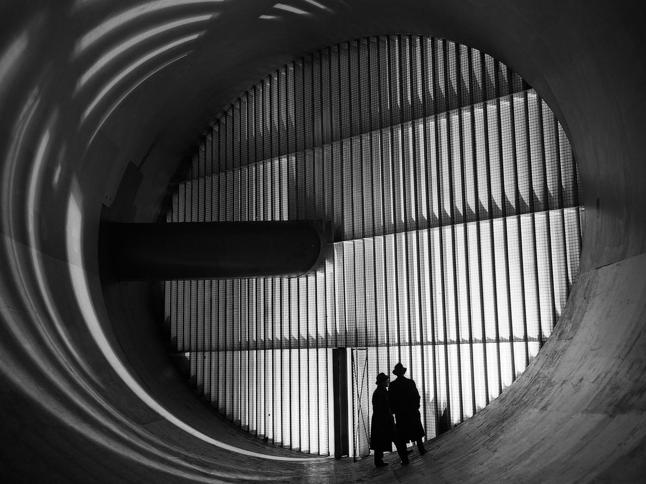
Men stand in front of turning vanes inside the Altitude Wind Tunnel (AWT) at the National Advisory Committee for Aeronautics (NACA) Aircraft Engine Research Laboratory. The AWT was the only wind tunnel capable of testing full-size aircraft engines in simulated altitude conditions. A large wooden drive fan, located on the other side of these vanes, created wind speeds up to 500 miles per hour. The drive shaft connected the fan to the induction motor located in an adjacent building. Turning vanes were located in each corner of the rectangular tunnel to straighten the airflow and direct it around the corners. This set of vanes was located in the 31-foot-diameter southeast corner of the tunnel. These elliptical panels consisted of 36 to 42 vertical vanes that were supported by three horizontal supports. The individual vanes were 2.5 feet long and half-moon shaped. The panel of vanes was affixed to the curved corner rings of the tunnel. Each set of turning vanes had a moveable vane in the middle of the lower level for personnel access. Each set of vanes took weeks to assemble before they were installed during the summer of 1943. This publicity photograph was taken just weeks after the tunnel became operational in February 1944.
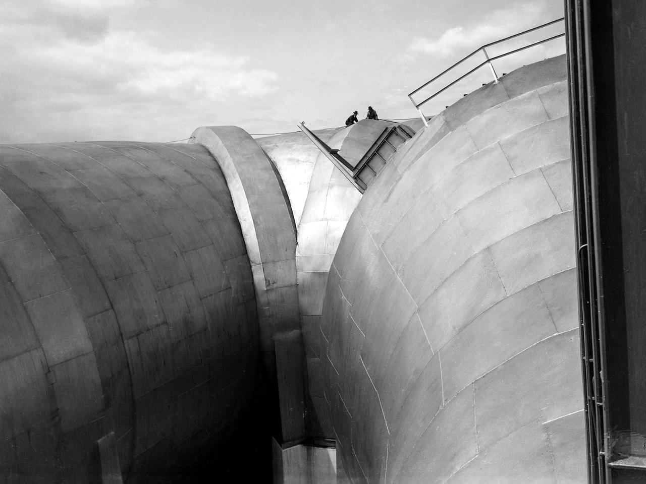
Two men on top of the Altitude Wind Tunnel (AWT) at the National Advisory Committee for Aeronautics (NACA) Aircraft Engine Research Laboratory. The tunnel was a massive rectangular structure, which for years provided one of the highest vantage points on the laboratory. The tunnel was 263 feet long on the north and south legs and 121 feet long on the east and west sides. The larger west end of the tunnel, seen here, was 51 feet in diameter. The east side of the tunnel was 31 feet in diameter at the southeast corner and 27 feet in diameter at the northeast. The throat section, which connected the northwest corner to the test section, narrowed sharply from 51 to 20 feet in diameter. The AWT’s altitude simulation required temperature and pressure fluctuations that made the design of the shell more difficult than other tunnels. The simultaneous decrease in both pressure and temperature inside the facility produced uneven stress loads, particularly on the support rings. The steel used in the primary tunnel structure was one inch thick to ensure that the shell did not collapse as the internal air pressure was dropped to simulate high altitudes. It was a massive amount of steel considering the World War II shortages. The shell was covered with several inches of fiberglass insulation to retain the refrigerated air and a thinner outer steel layer to protect the insulation against the weather. A unique system of rollers was used between the shell and its support piers. These rollers allowed for movement as the shell expanded or contracted during the altitude simulations. Certain sections would move as much as five inches during operation.

These compressors inside the Refrigeration Building at the National Advisory Committee for Aeronautics (NACA) Aircraft Engine Research Laboratory were used to generate cold temperatures in the Altitude Wind Tunnel (AWT) and Icing Research Tunnel. The AWT was a large facility that simulated actual flight conditions at high altitudes. The two primary aspects of altitude simulation are the reduction of the air pressure and the decrease of temperature. The Icing Research Tunnel was a smaller facility in which water droplets were added to the refrigerated air stream to simulate weather conditions that produced ice buildup on aircraft. The military pressured the NACA to complete the tunnels quickly so they could be of use during World War II. The NACA engineers struggled with the design of this refrigeration system, so Willis Carrier, whose Carrier Corporation had pioneered modern refrigeration, took on the project. The Carrier engineers devised the largest cooling system of its kind in the world. The system could lower the tunnels’ air temperature to –47⁰ F. The cooling system was powered by 14 Carrier and York compressors, seen in this photograph, which were housed in the Refrigeration Building between the two wind tunnels. The compressors converted the Freon 12 refrigerant into a liquid. The refrigerant was then pumped into zig-zag banks of cooling coils inside the tunnels’ return leg. The Freon absorbed heat from the airflow as it passed through the coils. The heat was transferred to the cooling water and sent to the cooling tower where it was dissipated into the atmosphere.