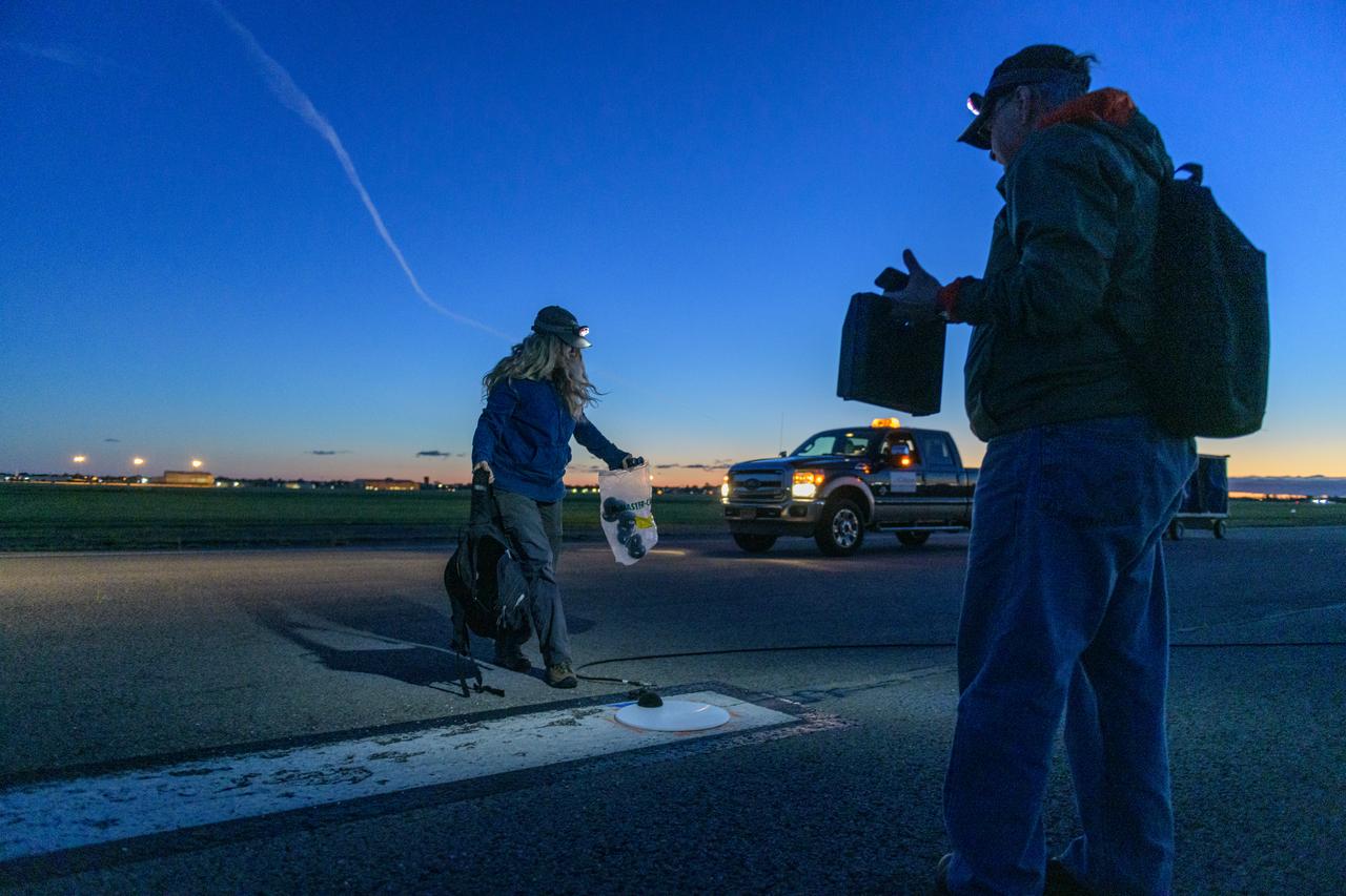
Learjet 25 Acoustic Measurement Testing at Niagara Falls, New York Airport
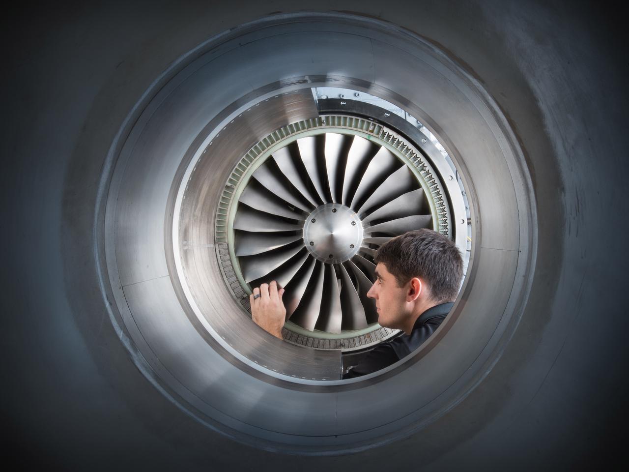
Acoustic Casing Treatment Testing Completed in the W-8 Single Stage Axial Compressor Facility at NASA Glenn. Four different over-the-rotor acoustic casing treatment concepts were tested along with two baseline configurations. Testing included steady-aerodynamic measurements of fan performance, hotfilm turbulence measurements, and inlet acoustic measurements with an in-duct array.
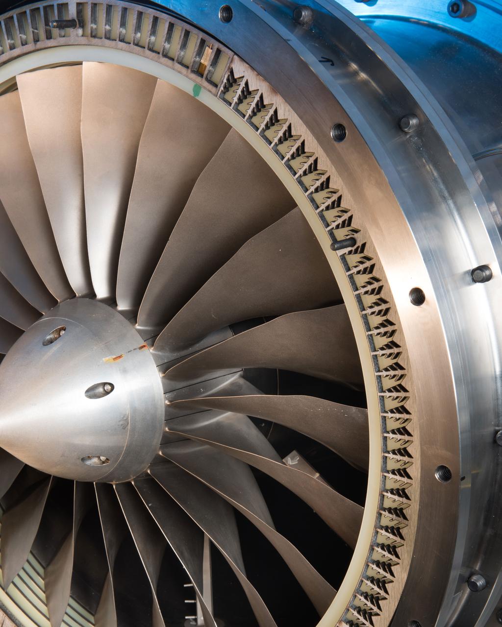
Acoustic Casing Treatment Testing Completed in the W-8 Single Stage Axial Compressor Facility at NASA Glenn. Four different over-the-rotor acoustic casing treatment concepts were tested along with two baseline configurations. Testing included steady-aerodynamic measurements of fan performance, hotfilm turbulence measurements, and inlet acoustic measurements with an in-duct array.

Title: W-8 Fan Acoustic Casing Treatment Test on the Source Diagnostic Test Rotor Alone Hardware Program: Advanced Air Vehicles Program (AAVP) Project: Advanced Air Transport Technology (AATT) Sub-project: Aircraft Noise Reduction (ANR) Weekly Highlight: · Acoustic Casing Treatment Testing Completed in the W-8 Single Stage Axial Compressor Facility: Testing of Acoustic Casing Treatments on the Source Diagnostic Test (SDT) rotor alone hardware which had begun in early January was completed on Thursday, February 16th. Four different over-the-rotor acoustic casing treatment concepts were tested along with two baseline configurations. Testing included steady-aerodynamic measurements of fan performance, hotfilm turbulence measurements, and inlet acoustic measurements with an in-duct array. These measurements will be used to assess the aerodynamic and acoustic impact of fan acoustic casing treatments on a high bypass ratio fan at TRL 3. This test was the last of 3 planned tests of potential over-the-rotor acoustic casing treatments. The first treatment test was completed in the Normal Incidence Tube (NIT) at Langley Research Center (LaRC) in Fall 2015 and the second was completed on the Advanced Noise Control Fan (ANCF) in the Aero-Acoustic Propulsion Laboratory (AAPL) in Winter 2016. This work is supported by the Aircraft Noise Reduction (ANR) subproject of the Advanced Air Transport Technology (AATT) Project. (POC: LTV/ Rick Bozak 3-5160)
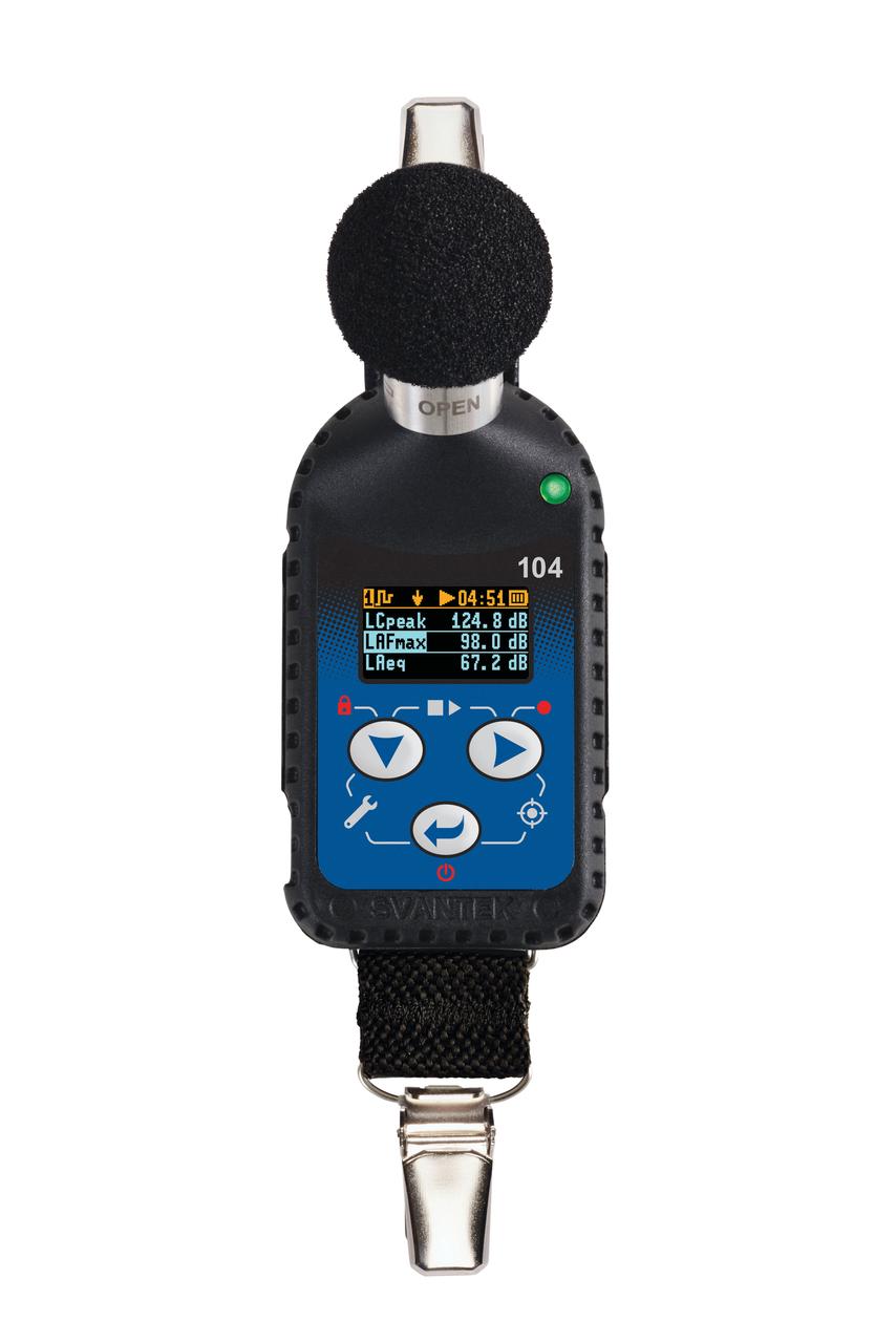
jsc2025e044837 2/19/2019) --- Shown is the SV104A noise dosimeter that measures noise dose and noise levels in the large measurement range of 55 dB to 140 dB aboard the International Space Station. This dosimeter is part of A Next Generation Crew Health & Performance Acoustic Monitoring Capability for Exploration: An International Space Station Technology Demonstration (Wireless Acoustics) investigation. Image courtesy of SVANTEK.
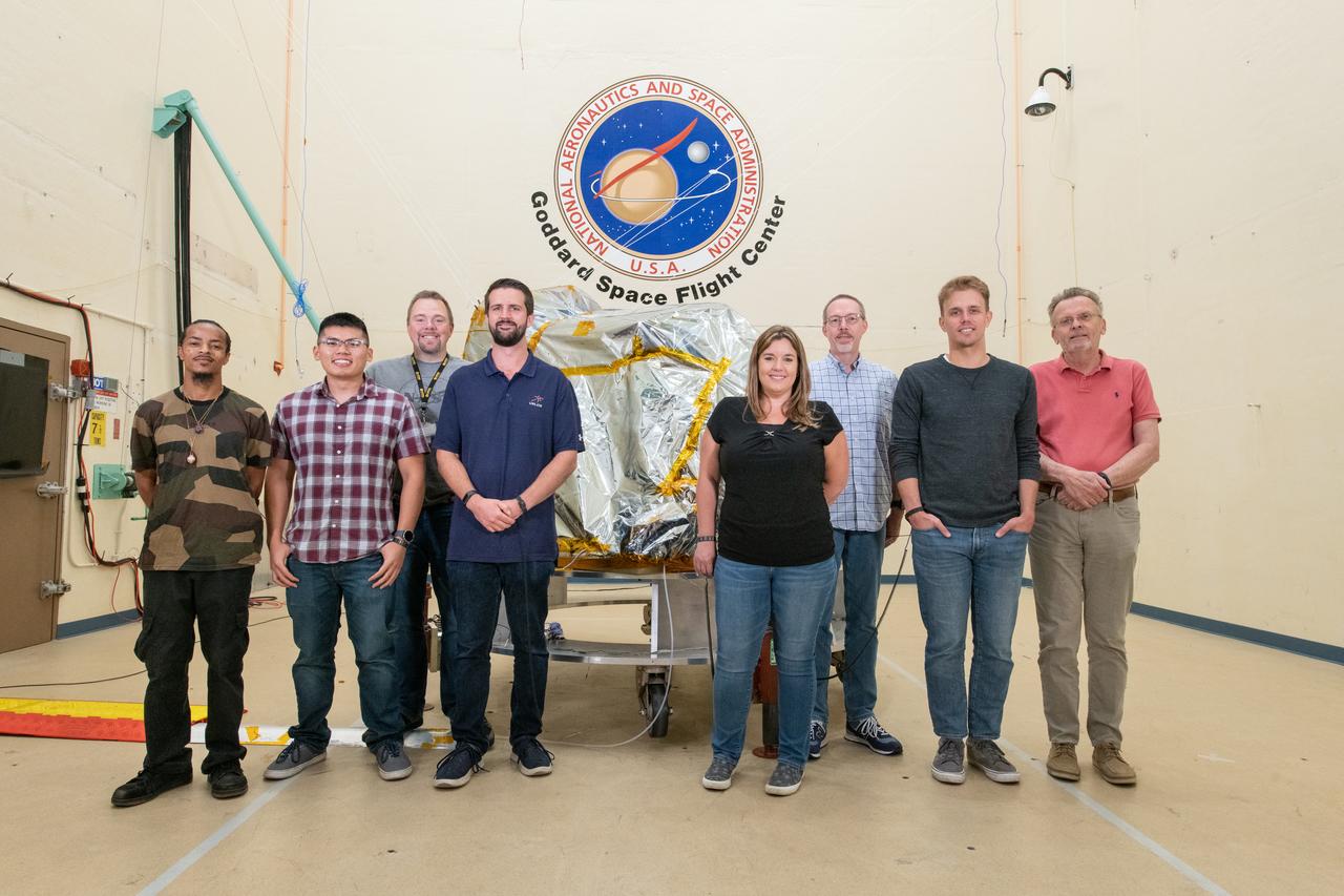
The Goddard Space Flight Center (GSFC) environmental testing team poses with the bagged Ocean Color Instrument (OCI) behind them in the acoustic chamber prior to testing. The acoustic testing will ensure that functionality of OCI is not impaired by severe launch environments. OCI is a highly advanced optical spectrometer that will be used to measure properties of light over portions of the electromagnetic spectrum. It will enable continuous measurement of light at finer wavelength resolution than previous NASA satellite sensors, extending key system ocean color data records for climate studies. OCI is PACE's (Plankton, Aerosol, Cloud, ocean Ecosystem) primary sensor built at Goddard Space Flight Center in Greenbelt, MD.
New testing is underway in the Aero-Acoustic Propulsion Laboratory (AAPL) at NASA's Glenn Research Center. The research focuses on a model called the Highly Variable Cycle Exhaust System -- a 0.17 scale model of an exhaust system that will operate at subsonic, transonic and supersonic exhaust speeds in a future supersonic business jet. The model features ejector doors used at different angles. Researchers are investigating the impact of these ejectors on the resulting acoustic radiation. Here, Steven Sedensky, a mechanical engineer with Jacobs Sverdrup, takes measurements of the ejector door positions.
The S0 Truss is moved into the highbay of bldg 49 for Space Station Module acoustic test. Views include: S0 Truss moved into bldg 49 highbay (17342-53, 17370-71); a measuring stick is held near Truss (17354); Truss in acoustic chamber (17355-61, 17367); Truss in air above cradle (17362, 17364-66, 17368); Truss in cradle (17363).
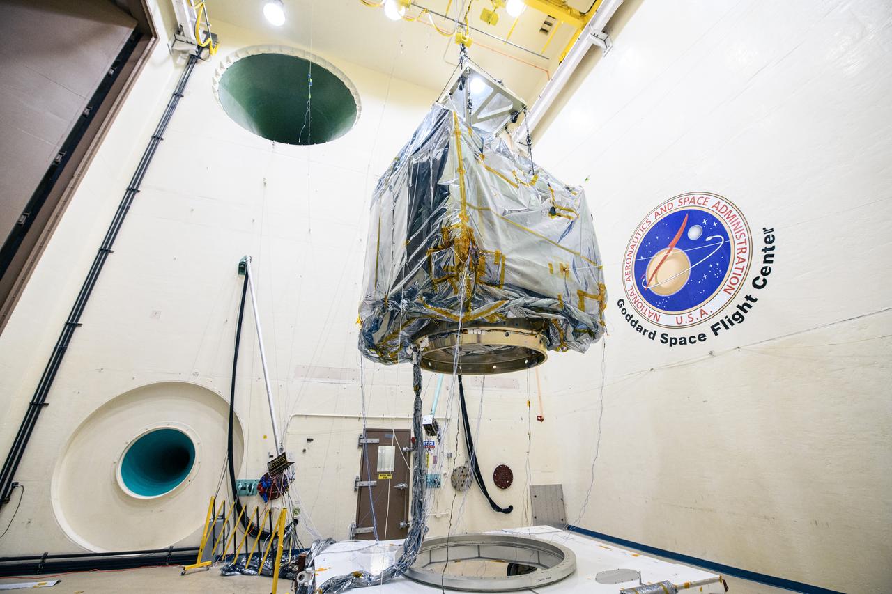
The Plankton, Aerosol, Cloud, ocean Ecosystem (PACE) observatory suspended for acoustic testing in the acoustic test facility at NASA's Goddard Space Flight Center in Greenbelt, Maryland on April 17th, 2023. PACE's unprecedented spectral coverage will provide the first-ever global measurements designed to identify phytoplankton community composition. The mission will make global ocean color measurements, using the Ocean Color Instrument (OCI), to provide extended data records on ocean ecology and global biogeochemistry along with polarimetry measurements, using the Spectro-polarimeter for Planetary Exploration (SPEXone) and the Hyper Angular Research Polarimeter (HARP2) to provide extended data records on clouds and aerosols. The Earth-observing satellite mission, built at Goddard Space Flight Center in Greenbelt, MD, will continue and advance observations of global ocean color, biogeochemistry, and ecology, as well as the carbon cycle, aerosols and clouds.
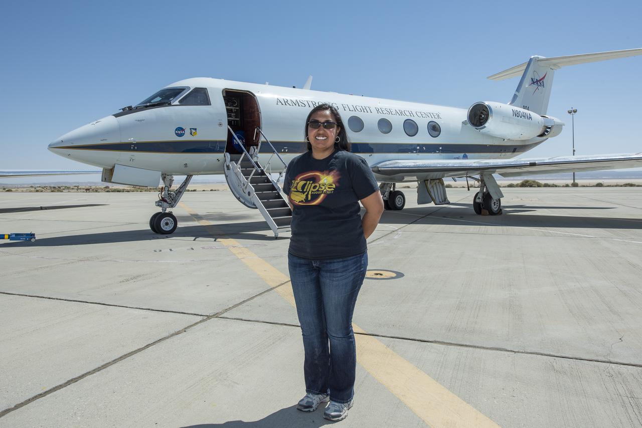
Claudia Sales, NASA’s acting X-59 deputy chief engineer and airworthiness certification lead for the quiet supersonic research aircraft, supports ground testing for Acoustic Research Measurements (ARM) flights. The test campaign to evaluate technologies that reduce aircraft noise was conducted at NASA’s Armstrong Flight Research Center in Edwards, California, in 2018.
A NASA TG-14 glider aircraft is prepared for flight at NASA’s Armstrong Flight Research Center in Edwards, California, in support of the agency’s Quesst mission. The aircraft is equipped with onboard microphones to capture sonic boom noise generated during rehearsal flights, helping researchers measure the acoustic signature of supersonic aircraft closer to the ground.
Claudia Sales, NASA’s acting X-59 deputy chief engineer and airworthiness certification lead for the quiet supersonic research aircraft, stands in front of a Gulfstream G-III, also known as Subsonic Research Aircraft Testbed (SCRAT). Sales supported ground testing as test conductor for Acoustics Research Measurements (ARM) flights at NASA’s Armstrong Research Flight Center in Edwards, California, in 2018.
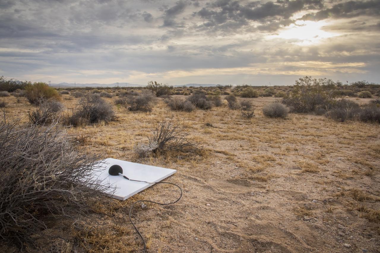
One of multiple microphone stations used in the CarpetDIEM flight series, which gave researchers valuable lessons learned in preparations to deploy a similar array for the quiet supersonic X-59. Prior to community overflights, X-59 will undergo an acoustic validation phase, during which NASA will deploy the array of specially-configured microphones to measure the X-59’s thumps, in order to verify that they are as quiet as predicted.
Dr. Forrest Carpenter, left, principal investigator for the third phase of CarpetDIEM, Carpet Determination in Entirety Measurements flights, monitors a test from one of the control rooms at NASA’s Armstrong Flight Research Center. Next to Carpenter is Brian Strovers, chief engineer for Commercial Supersonic Technology. The third phase of CarpetDIEM tested logistics and upgraded ground recording systems in preparation for the acoustic validation phase of the Quesst mission.
Aerospace engineer Larry Cliatt, Quesst Phase 2 Sub-Project Manager abd technical lead for the acoustic validation phase of the Quesst mission, sets up a ground recording system in the California desert. The Quesst mission recently completed testing of operations and equipment to be used in recording the sonic thumps of the X-59. The testing was the third phase of Carpet Determination in Entirety Measurements flights, called CarpetDIEM for short. An F-15 and an F-18 from NASA’s Armstrong Flight Research Center created sonic booms, both loud and soft, to verify the operations of ground recording systems spread out across 30 miles of open desert.
Aerospace engineer Larry Cliatt, Quesst Phase 2 Sub-Project Manager and technical lead for the acoustic validation phase of the Quesst mission, sets up a ground recording system in the California desert. The Quesst mission recently completed testing of operations and equipment to be used in recording the sonic thumps of the X-59. The testing was the third phase of Carpet Determination in Entirety Measurements flights, called CarpetDIEM for short. An F-15 and an F-18 from NASA’s Armstrong Flight Research Center created sonic booms, both loud and soft, to verify the operations of ground recording systems spread out across 30 miles of open desert.
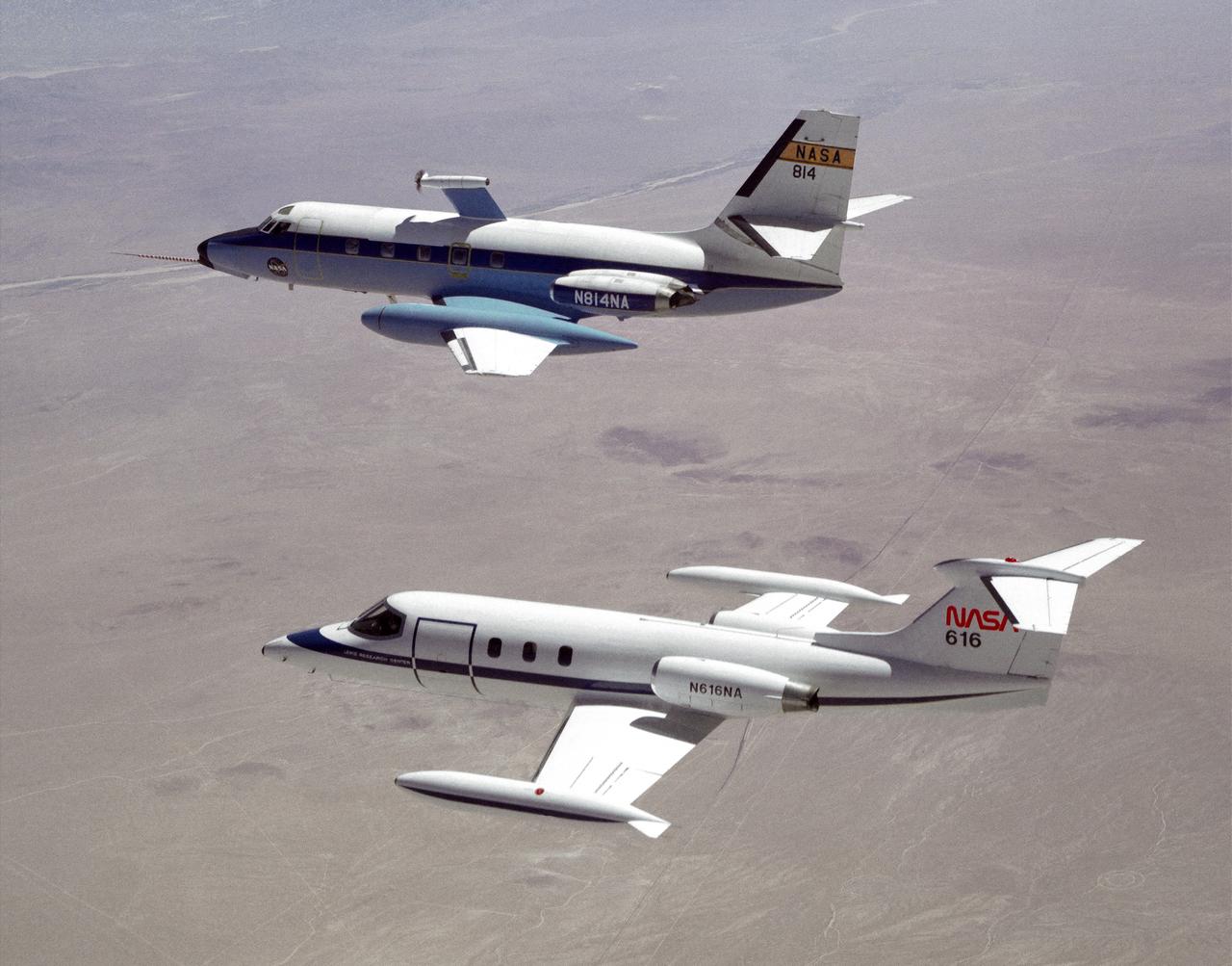
The NASA C-140 JetStar research aircraft (top) is followed by a NASA Learjet equipped with acoustic sensors during one of several tests of advanced propellors mounted on the vertical pylon atop the JetStar's fuselage. Several advanced prop designs were tested on the JetStar in 1982 by NASA's Dryden Flight Research Facility (DFRF), Edwards, California, to study the effects of noise created by propellors on aircraft structures and cabin interiors. To assess possible noise problems with the subscale turbofan, DFRF technicians mounted microphones on both the JetStar and the Learjet chase plane. DFRF then made measurements at close range and at longer distances. The data enabled structural changes and flightpath modifications.
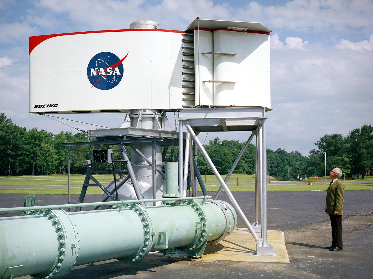
The augmentor wing concept was introduced during the early 1960s to enhance the performance of vertical and short takeoff (VSTOL) aircraft. The leading edge of the wing has full-span vertical flaps, and the trailing edge has double-slotted flaps. This provides aircraft with more control in takeoff and landing conditions. The augmentor wing also produced lower noise levels than other VSTOL designs. In the early 1970s Boeing Corporation built a Buffalo C-8A augmentor wing research aircraft for Ames Research Center. Researches at Lewis Research Center concentrated their efforts on reducing the noise levels of the wing. They initially used small-scale models to develop optimal nozzle screening methods. They then examined the nozzle designs on a large-scale model, seen here on an external test stand. This test stand included an airflow system, nozzle, the augmentor wing, and a muffler system below to reduce the atmospheric noise levels. The augmentor was lined with noise-reducing acoustic panels. The Lewis researchers were able to adjust the airflow to simulate conditions at takeoff and landing. Once the conditions were stabilized they took noise measurements from microphones placed in all directions from the wing, including an aircraft flying over. They found that the results coincided with the earlier small-scale studies for landing situations but not takeoffs. The acoustic panels were found to be successful.
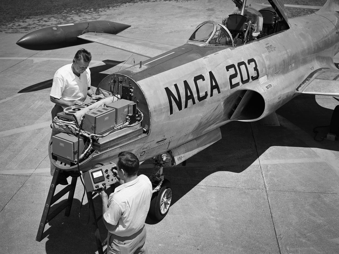
A Lockheed F-94B Starfire being equipped with an audio recording machine and sensors at the National Advisory Committee for Aeronautics (NACA) Lewis Flight Propulsion Laboratory. The NACA was investigating the acoustic effects caused by the engine’s nozzle and the air flowing along the fuselage. Airline manufacturers would soon be introducing jet engines on their passenger aircraft, and there was concern regarding the noise levels for both the passengers and public on the ground. NACA Lewis conducted a variety of noise reduction studies in its wind tunnels, laboratories, and on a F2H-2B Banshee aircraft. The F2H-2B Banshee’s initial test flights in 1955 and 1956 measured the noise emanating directly from airflow over the aircraft’s surfaces, particularly the wings. This problem was particularly pronounced at high subsonic speeds. The researchers found the majority of the noise occurred in the low and middle octaves. These investigations were enhanced with a series of flights using the F-94B Starfire. The missions measured wall-pressure, turbulence fluctuations, and mean velocity profiles. Mach 0.3 to 0.8 flights were flown at altitudes of 10,000, 20,000, and 30,000 feet with microphones mounted near the forward fuselage and on a wing. The results substantiated the wind tunnel findings. This photograph shows the tape recorder being installed in the F-94B’s nose.
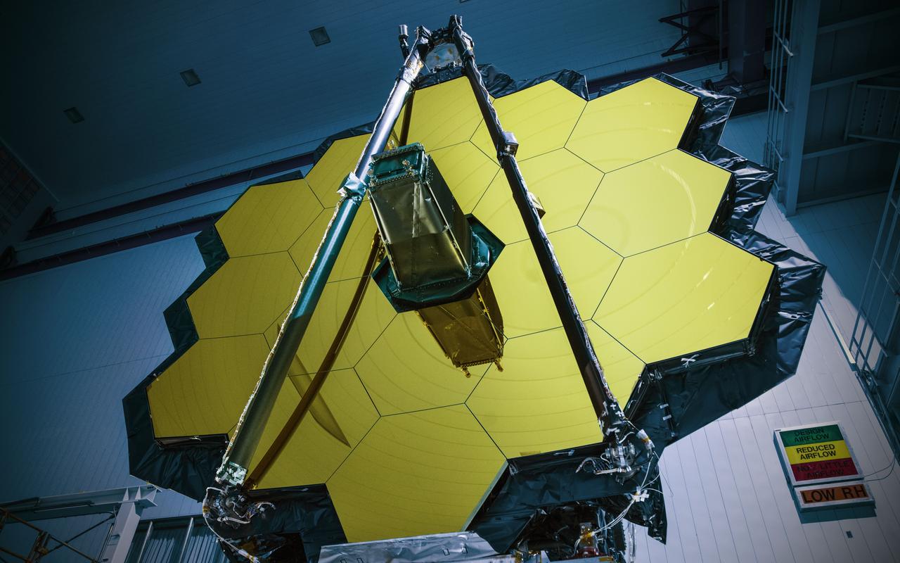
NASA’s James Webb Space Telescope has successfully passed the center of curvature test, an important optical measurement of Webb’s fully assembled primary mirror prior to cryogenic testing, and the last test held at NASA's Goddard Space Flight Center in Greenbelt, Maryland, before the spacecraft is shipped to NASA’s Johnson Space Center in Houston for more testing. After undergoing rigorous environmental tests simulating the stresses of its rocket launch, the Webb telescope team at Goddard analyzed the results from this critical optical test and compared it to the pre-test measurements. The team concluded that the mirrors passed the test with the optical system unscathed. “The Webb telescope is about to embark on its next step in reaching the stars as it has successfully completed its integration and testing at Goddard. It has taken a tremendous team of talented individuals to get to this point from all across NASA, our industry and international partners, and academia,” said Bill Ochs, NASA’s Webb telescope project manager. “It is also a sad time as we say goodbye to the Webb Telescope at Goddard, but are excited to begin cryogenic testing at Johnson.” Rocket launches create high levels of vibration and noise that rattle spacecraft and telescopes. At Goddard, engineers tested the Webb telescope in vibration and acoustics test facilities that simulate the launch environment to ensure that functionality is not impaired by the rigorous ride on a rocket into space. Before and after these environmental tests took place, optical engineers set up an interferometer, the main device used to measure the shape of the Webb telescope’s mirror. An interferometer gets its name from the process of recording and measuring the ripple patterns that result when different beams of light mix and their waves combine or “interfere.” Waves of visible light are less than a thousandth of a millimeter long and optics on the Webb telescope need to be shaped and aligned even more accurately than that to work correctly. Making measurements of the mirror shape and position by lasers prevents physical contact and damage (scratches to the mirror). So, scientists use wavelengths of light to make tiny measurements. By measuring light reflected off the optics using an interferometer, they are able to measure extremely small changes in shape or position that may occur after exposing the mirror to a simulated launch or temperatures that simulate the subfreezing environment of space. During a test conducted by a team from Goddard, Ball Aerospace of Boulder, Colorado, and the Space Telescope Science Institute in Baltimore, temperature and humidity conditions in the clean room were kept incredibly stable to minimize fluctuations in the sensitive optical measurements over time. Even so, tiny vibrations are ever-present in the clean room that cause jitter during measurements, so the interferometer is a “high-speed” one, taking 5,000 “frames” every second, which is a faster rate than the background vibrations themselves. This allows engineers to subtract out jitter and get good, clean results on any changes to the mirror's shape. Credit: NASA/Goddard/Chris Gunn Read more: <a href="https://go.nasa.gov/2oPqHwR" rel="nofollow">go.nasa.gov/2oPqHwR</a> NASA’s Webb Telescope Completes Goddard Testing