3% Space shuttle Acoustics model test-11-150 in 11ft. wind tunnel on PAL Ramp
3% Space shuttle Acoustics model test-11-150 in 11ft. wind tunnel on PAL Ramp
3% Space shuttle Acoustics model test-11-150 in 11ft. wind tunnel on PAL Ramp
3% Space shuttle Acoustics model test-11-150 in 11ft. wind tunnel on PAL Ramp
3% Space shuttle Acoustics model test-11-150 in 11ft. wind tunnel on PAL Ramp
3% Space shuttle Acoustics model test-11-150 in 11ft. wind tunnel on PAL Ramp
3% Space shuttle Acoustics model test-11-150 in 11ft. wind tunnel on PAL Ramp
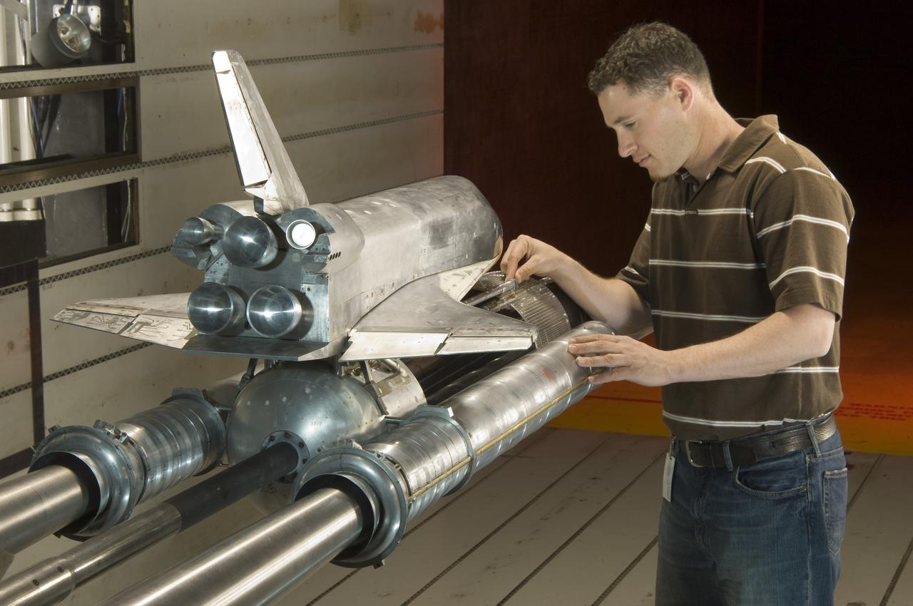
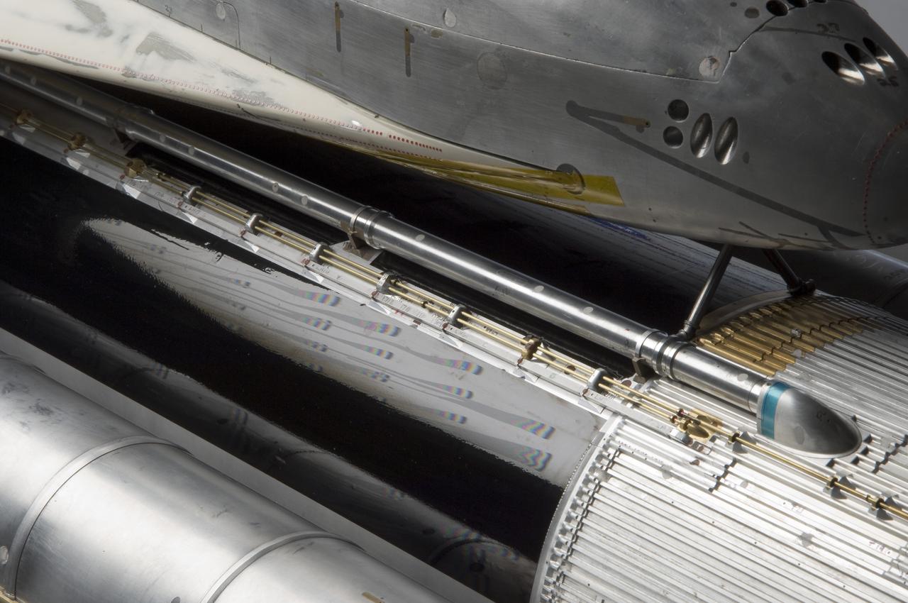
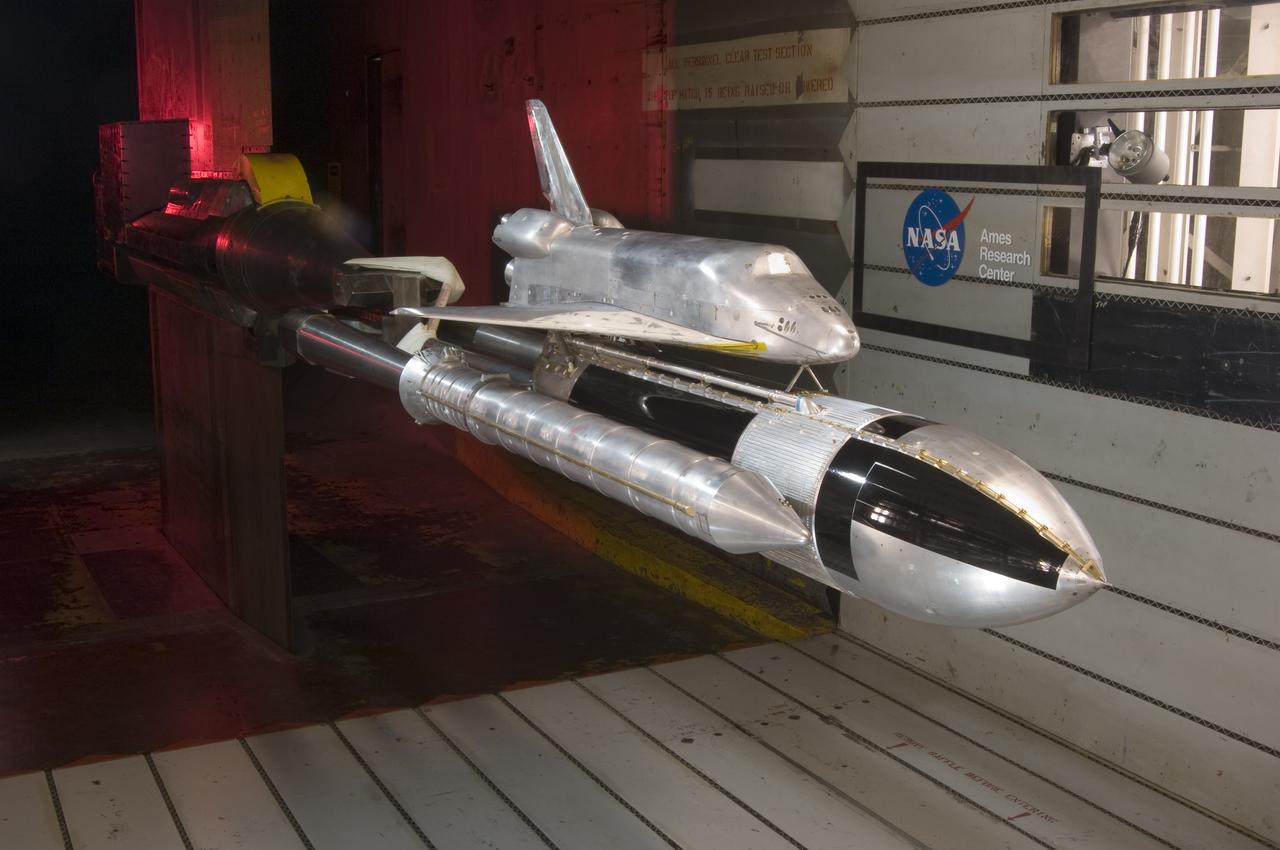
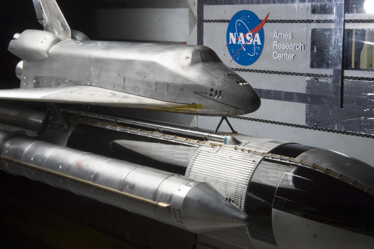
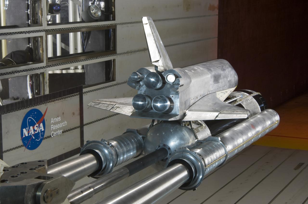
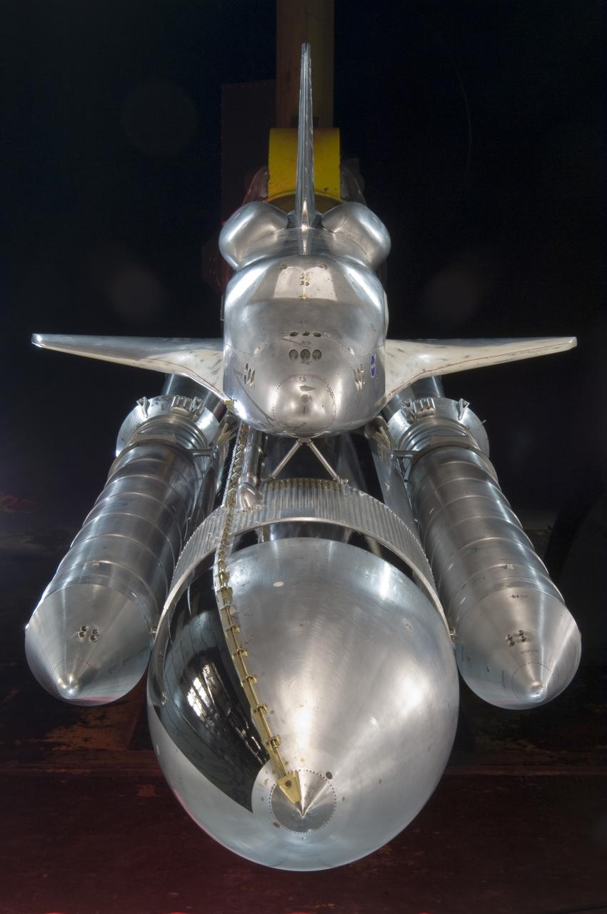
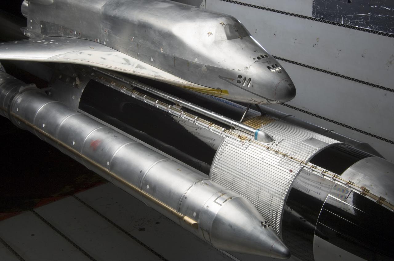
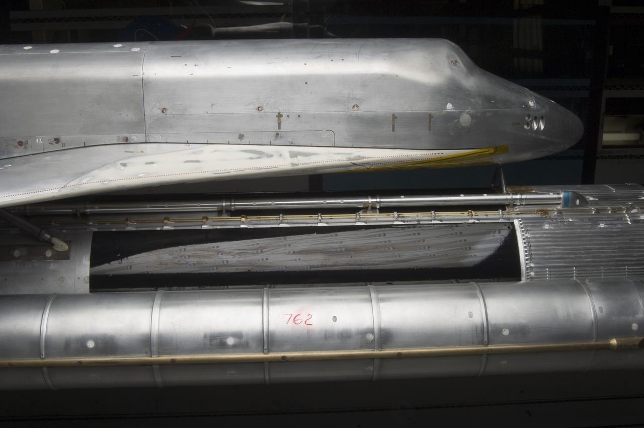
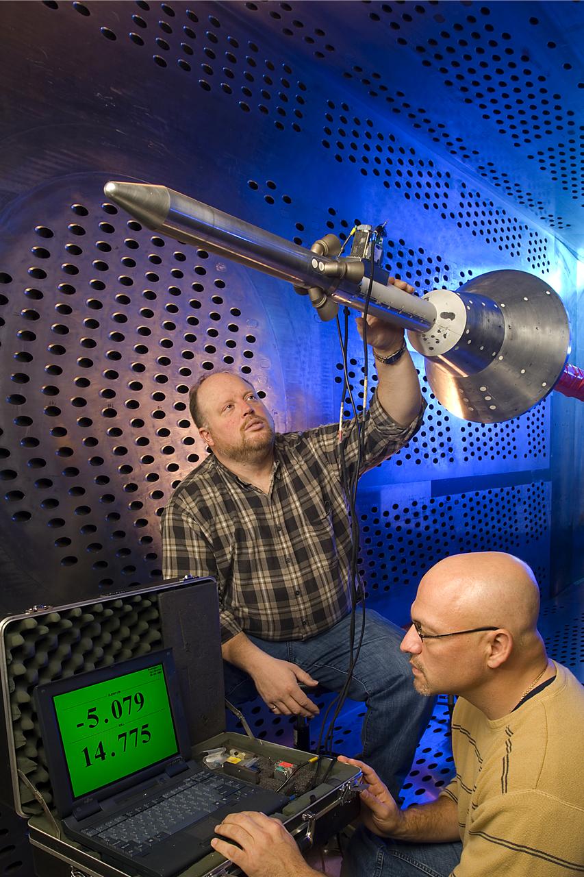
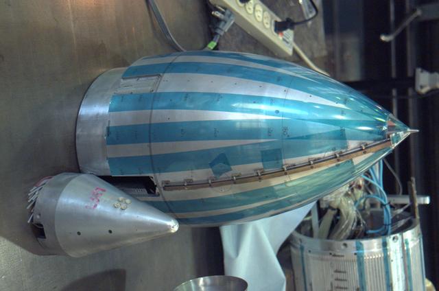
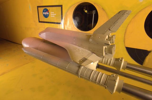
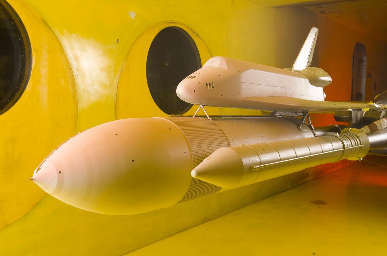
3% Space Shuttle Acoustics model test-11-150 in NASA Ames 11x11_foot. Transonic Wind Tunnel on PAL Ramp with Tim Steiger.
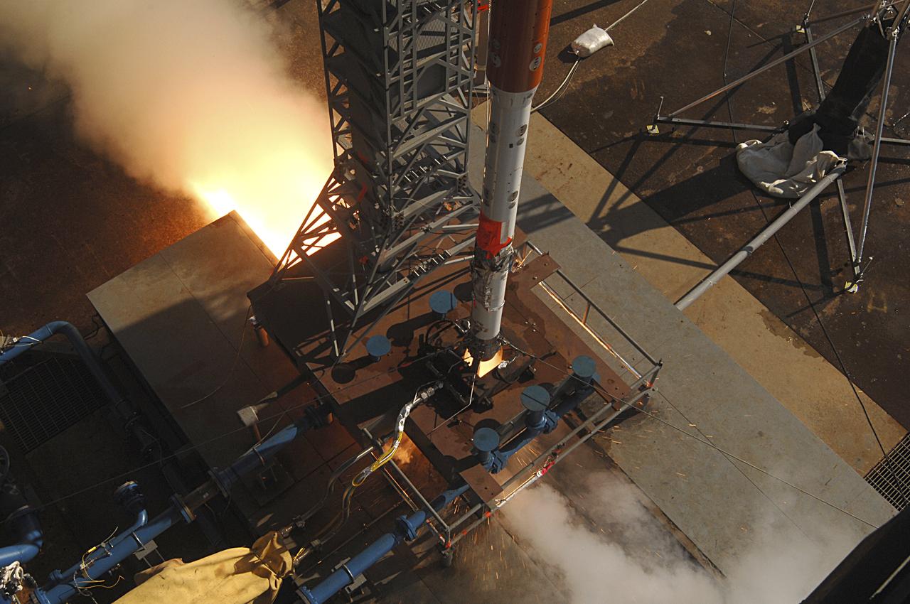
Project 8019 Vertical Ares Scale Model Acoustic Test (ASMAT) Ignition Over Pressure (IOP) Test #3, 11/18/2010 P8019_VERT 03-016
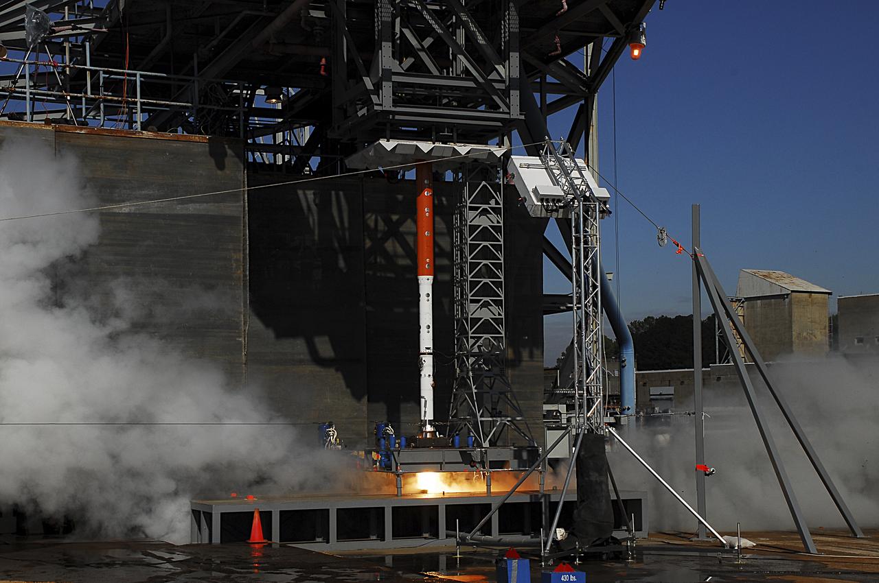
Project 8019 Vertical Ares Scale Model Acoustic Test (ASMAT) Ignition Over Pressure (IOP) Test #3, 11/18/2010 P8019_VERT 03-078
Orion Capsule and Launch Abort System (LAS) installed in the NASA Glenn 8x6 Supersonic Wind Tunnel for testing. This test is an Aero Acoustic test of the LAS. Pictured is the calibration of the model's angle of attack
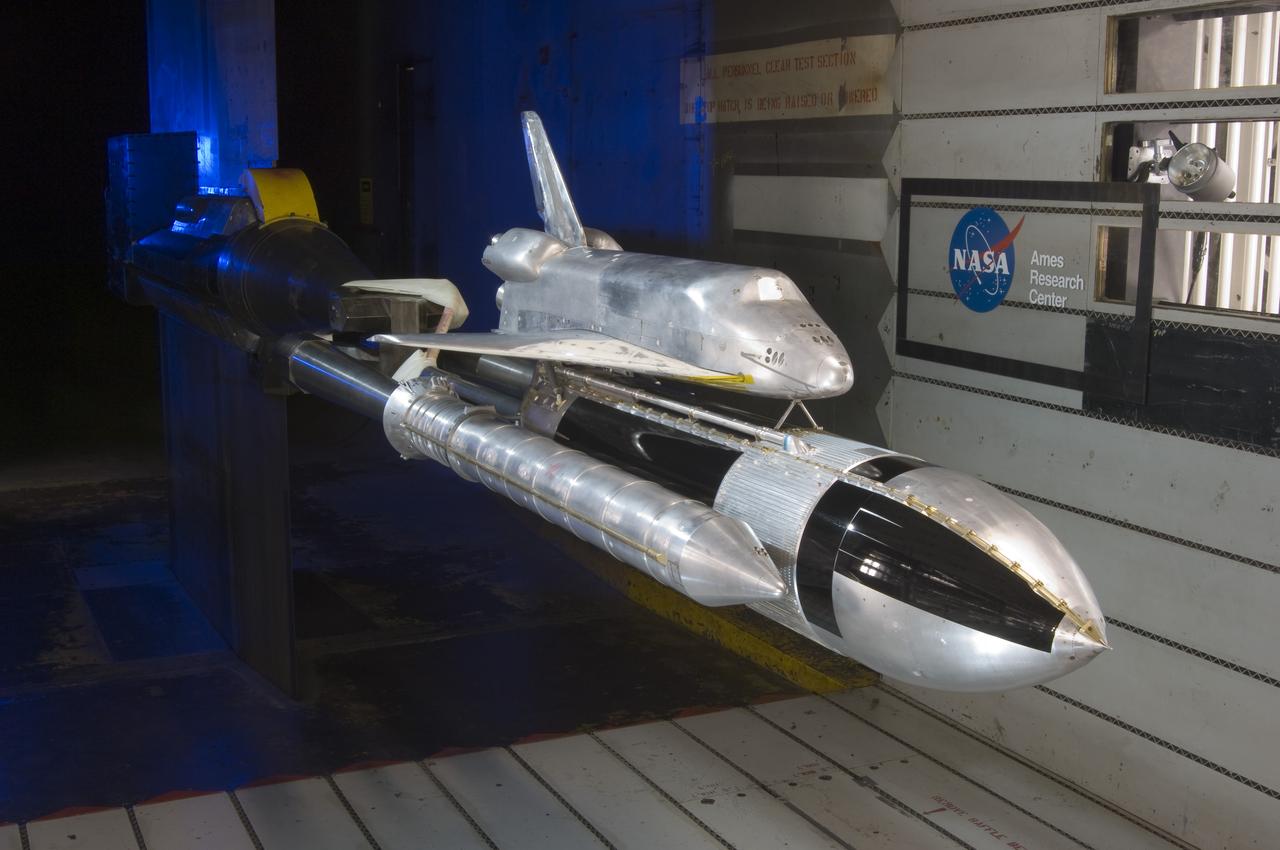
Space Shuttle 3% acoustics model with Pal ramp in Ames 11ft. w.t.
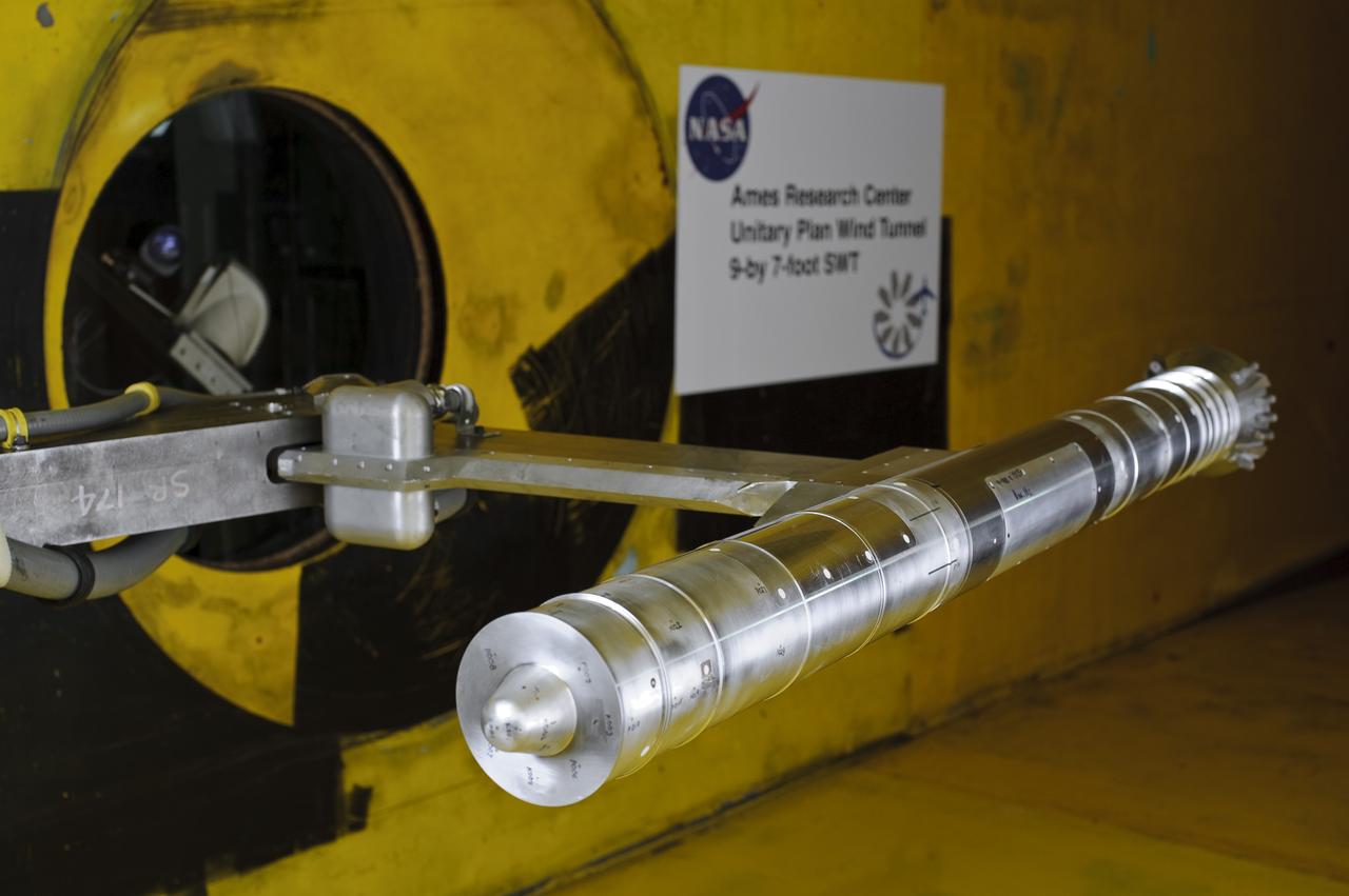
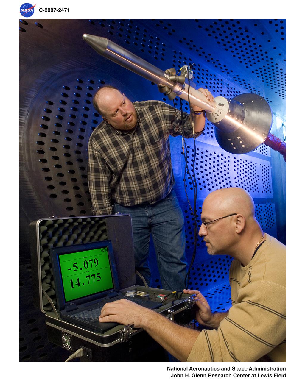
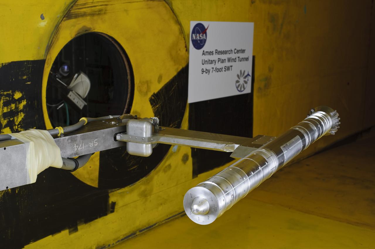
2.8% Ares I Acoustic Reentry Wind Tunnel Model in Ames 9X7ft Supersonic Wind Tunnel test-97-0193; model flying backwards in tunnel
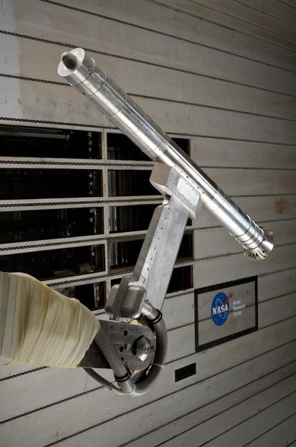
2.8% Scale Ares I acoustic model re-entry model in Ames 11ft. Supersonic Wind Tunnel test-11-0192
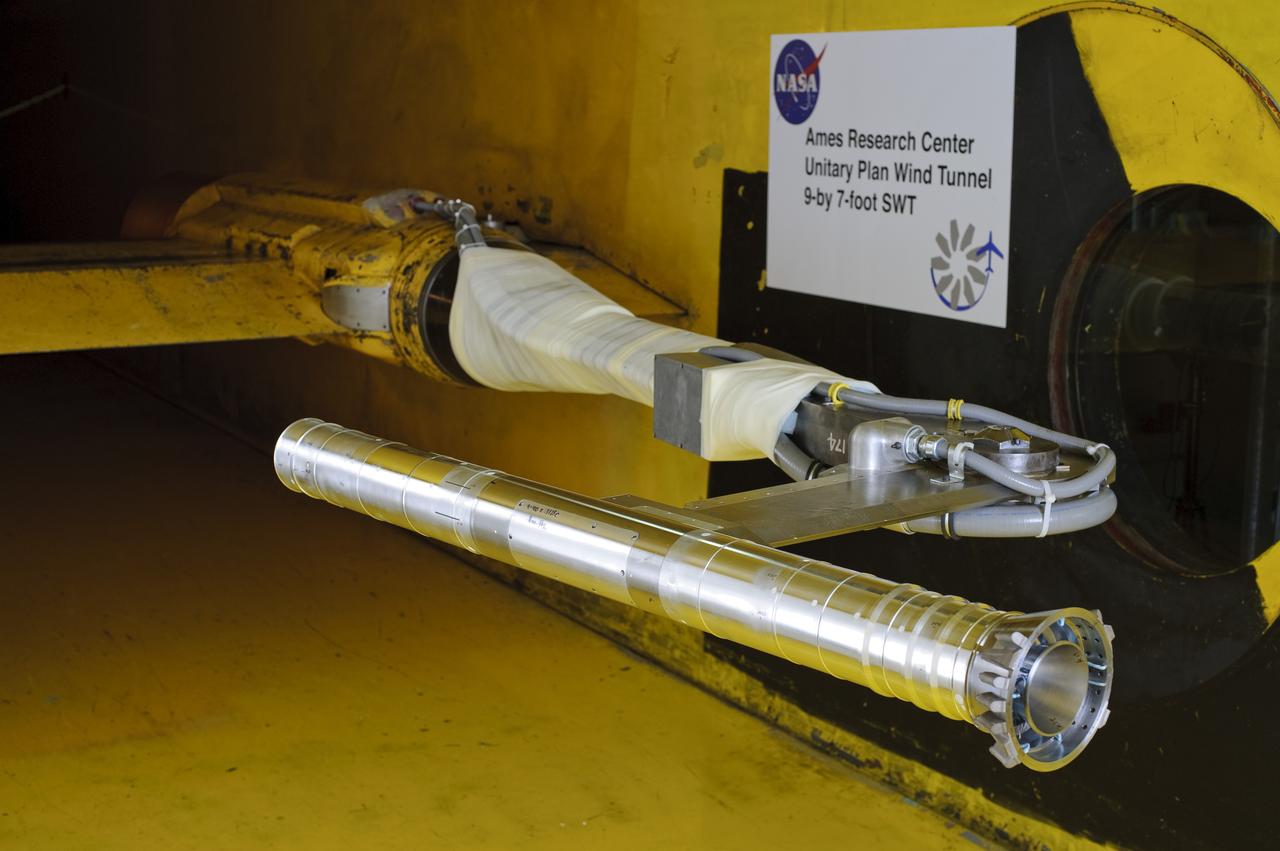
2.8% Ares I Acoustic Reentry Wind Tunnel Model in Ames 9X7ft Supersonic Wind Tunnel test-97-0193; model flying backwards in tunnel
2.8% Ares I Acoustic Reentry Wind Tunnel Model in Ames 9X7ft Supersonic Wind Tunnel test-97-0193; model flying backwards in tunnel
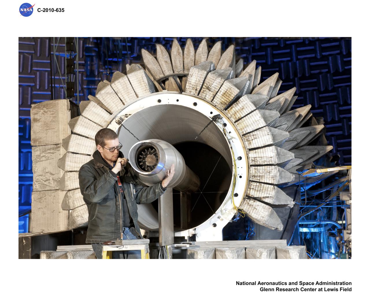
New testing is underway in the Aero-Acoustic Propulsion Laboratory (AAPL) at NASA's Glenn Research Center. The research focuses on a model called the Highly Variable Cycle Exhaust System -- a 0.17 scale model of an exhaust system that will operate at subsonic, transonic and supersonic exhaust speeds in a future supersonic business jet. The model features ejector doors used at different angles. Researchers are investigating the impact of these ejectors on the resulting acoustic radiation. Here, Steven Sedensky, a mechanical engineer with Jacobs Sverdrup, takes measurements of the ejector door positions.

Twin Jet Model, Nozzle Acoustic Test Rig, NATR, Aeroacoustic Propulsion Laboratory, AAPL
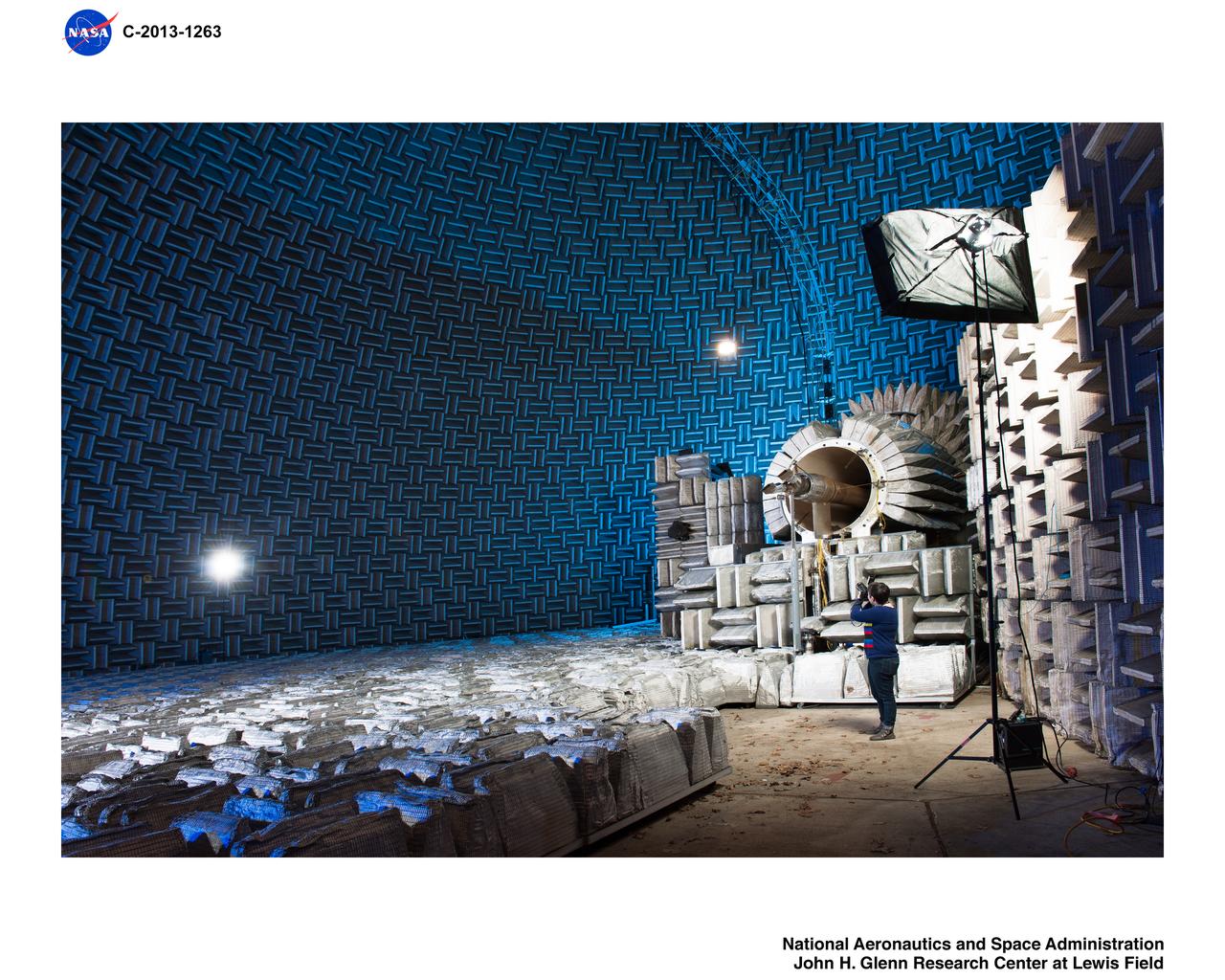
Twin Jet Model, Nozzle Acoustic Test Rig, NATR, Aeroacoustic Propulsion Laboratory, AAPL
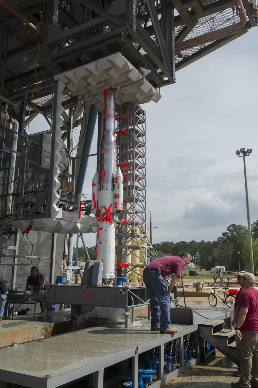
TEST ENGINEER DENNIS STRICKLAND CONDUCTS WATER FLOW TESTS AT TEST STAND 116 FOR SPACE LAUNCH SYSTEM SCALE MODEL ACOUSTIC TEST SERIES (WITH SOLID ROCKET BOOSTERS)
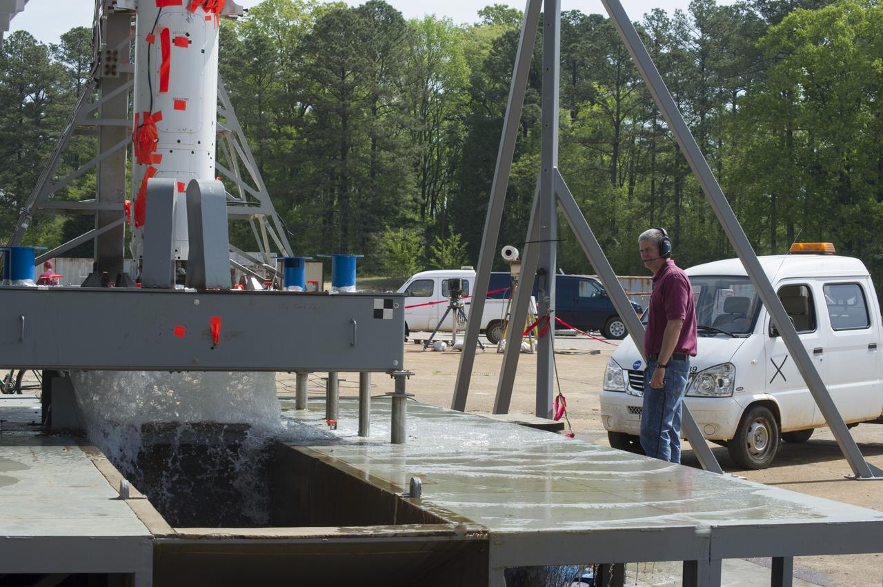
TEST ENGINEER DENNIS STRICKLAND CONDUCTS WATER FLOW TESTS AT TEST STAND 116 FOR SPACE LAUNCH SYSTEM SCALE MODEL ACOUSTIC TEST SERIES (WITH SOLID ROCKET BOOSTERS)
Orion Capsule and Launch Abort System (LAS) installed in the NASA Glenn 8x6 Supersonic Wind Tunnel for testing. This test is an Aero Acoustic test of the LAS. Pictured is the calibration of the model's angle of attack
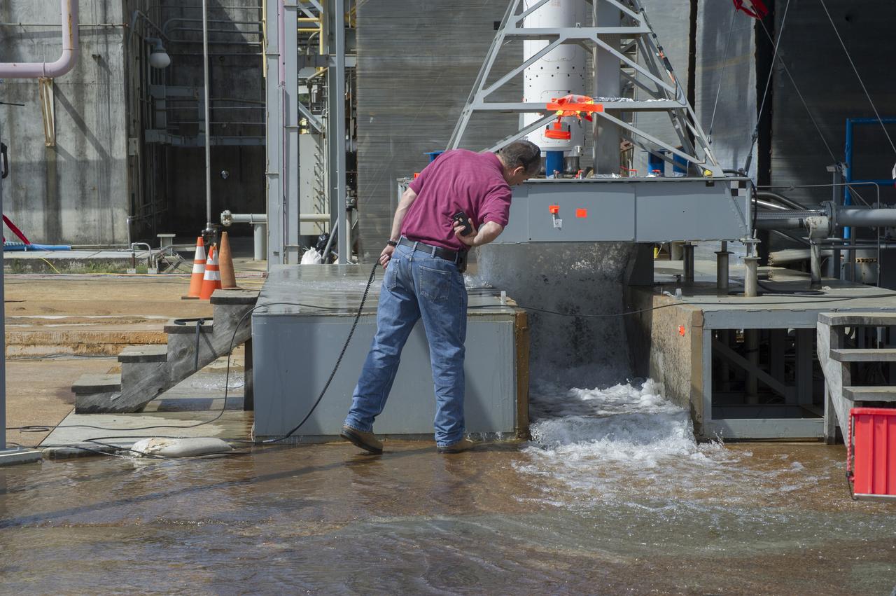
TEST ENGINEER DENNIS STRICKLAND CONDUCTS WATER FLOW TESTS AT TEST STAND 116 FOR SPACE LAUNCH SYSTEM SCALE MODEL ACOUSTIC TEST SERIES (WITH SOLID ROCKET BOOSTERS)

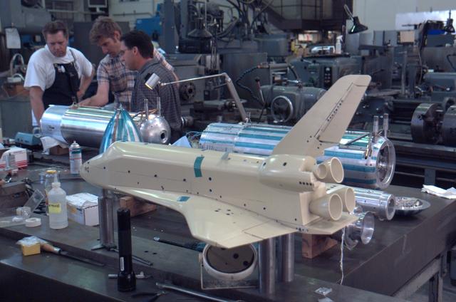
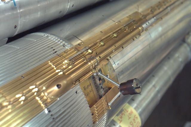
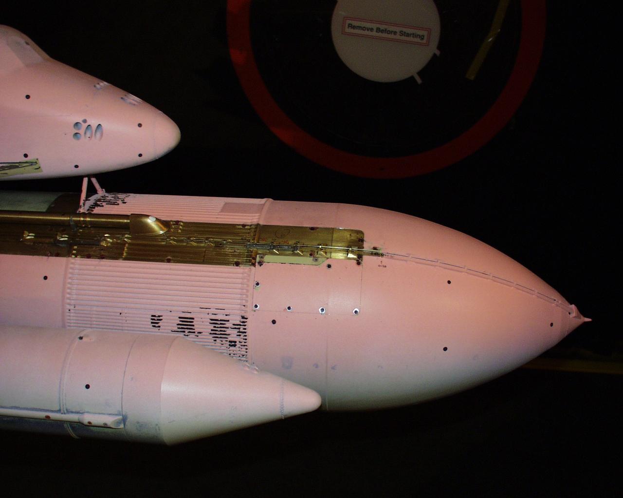
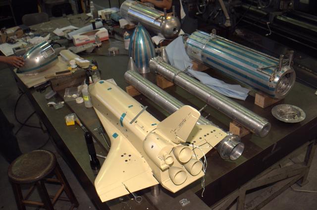
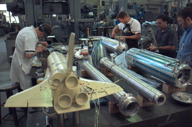
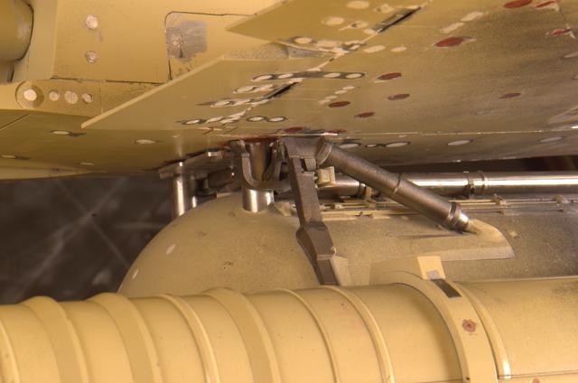
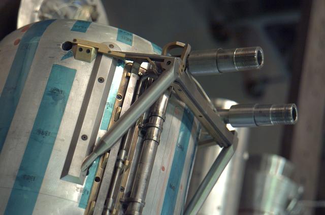
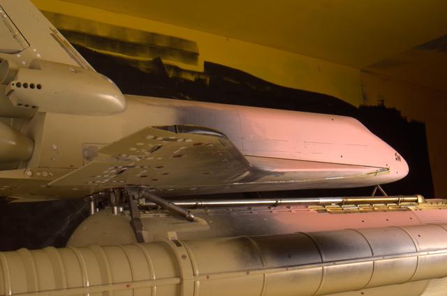
3% Space Shuttle Model preparation in Ames Machine Shop for Return to flight test to be run in the Ames 9X7ft wind tunnel test T97-0131 (IA-700B)
3% Space Shuttle Model preparation in Ames Machine Shop for Return to flight test to be run in the Ames 9X7ft wind tunnel test T97-0131 (IA-700B)
3% Space Shuttle Model preparation in Ames Machine Shop for Return to flight test to be run in the Ames 9X7ft wind tunnel test T97-0131 (IA-700B)
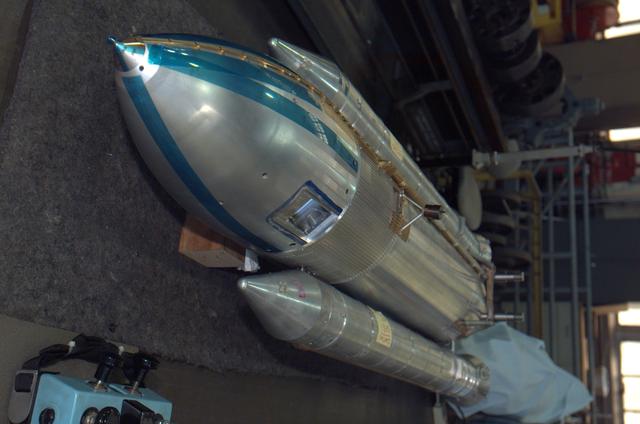
3% Space Shuttle Model preparation in Ames Machine Shop for Return to flight test to be run in the Ames 9X7ft wind tunnel test T97-0131 (IA-700B)
3% Space Shuttle Model Testing for Return to flight in the Ames 9X7ft wind tunnel test T97-0131 (IA-700B) with pressure sensitive paint
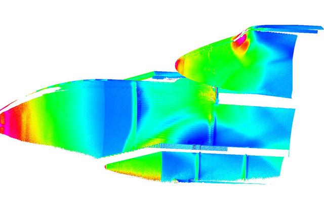
3% Space Shuttle Model Testing for Return to flight in the Ames 9X7ft wind tunnel test T97-0131 (IA-700B) showing data images created with pressure sensitive paint used on mode during the test run.
3% Space Shuttle Model preparation in Ames Machine Shop for Return to flight test to be run in the Ames 9X7ft wind tunnel test T97-0131 (IA-700B)
3% Space Shuttle Model preparation in Ames Machine Shop for Return to flight test to be run in the Ames 9X7ft wind tunnel test T97-0131 (IA-700B)
3% Space Shuttle Model preparation in Ames Machine Shop for Return to flight test to be run in the Ames 9X7ft wind tunnel test T97-0131 (IA-700B)
3% Space Shuttle Model Testing for Return to flight in the Ames 9X7ft wind tunnel test T97-0131 (IA-700B) with pressure sensitive paint
3% Space Shuttle Model Testing for Return to flight in the Ames 9X7ft wind tunnel test T97-0131 (IA-700B) with pressure sensitive paint
3% Space Shuttle Model preparation in Ames Machine Shop for Return to flight test to be run in the Ames 9X7ft wind tunnel test T97-0131 (IA-700B)
3% Space Shuttle Model Testing for Return to flight in the Ames 9X7ft wind tunnel test T97-0131 (IA-700B) with pressure sensitive paint
3% Space Shuttle Model preparation in Ames Machine Shop for Return to flight test to be run in the Ames 9X7ft wind tunnel test T97-0131 (IA-700B)
3% Space Shuttle Model Testing for Return to flight in the Ames 9X7ft wind tunnel test T97-0131 (IA-700B) with pressure sensitive paint
3% Space Shuttle Model preparation in Ames Machine Shop for Return to flight test to be run in the Ames 9X7ft wind tunnel test T97-0131 (IA-700B)
3% Space Shuttle Model Testing for Return to flight in the Ames 9X7ft wind tunnel test T97-0131 (IA-700B) with pressure sensitive paint
3% Space Shuttle Model Testing for Return to flight in the Ames 9X7ft wind tunnel test T97-0131 (IA-700B) with pressure sensitive paint
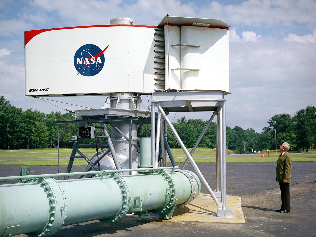
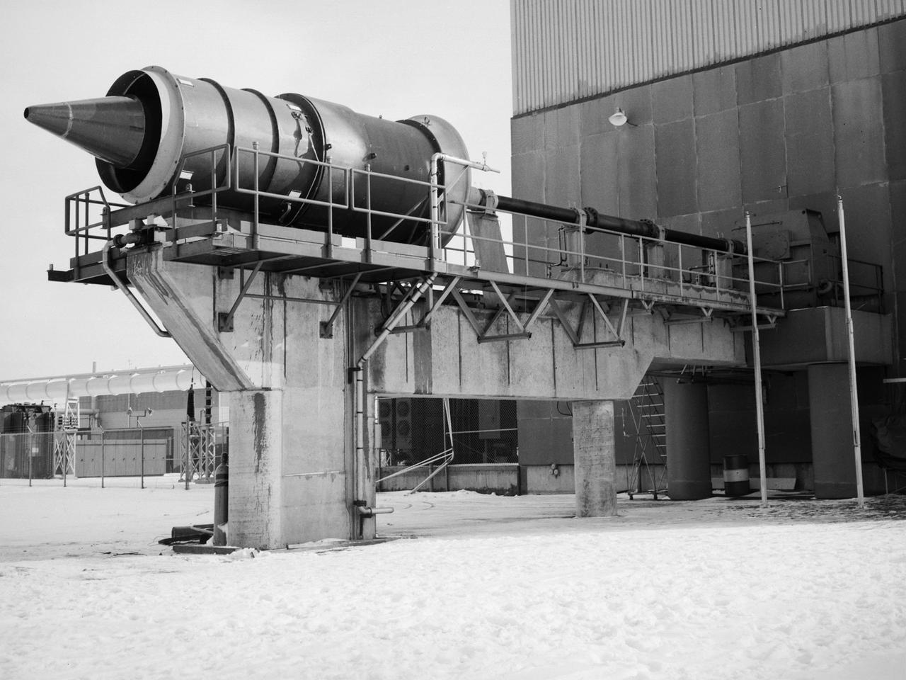
The augmentor wing concept was introduced during the early 1960s to enhance the performance of vertical and short takeoff (VSTOL) aircraft. The leading edge of the wing has full-span vertical flaps, and the trailing edge has double-slotted flaps. This provides aircraft with more control in takeoff and landing conditions. The augmentor wing also produced lower noise levels than other VSTOL designs. In the early 1970s Boeing Corporation built a Buffalo C-8A augmentor wing research aircraft for Ames Research Center. Researches at Lewis Research Center concentrated their efforts on reducing the noise levels of the wing. They initially used small-scale models to develop optimal nozzle screening methods. They then examined the nozzle designs on a large-scale model, seen here on an external test stand. This test stand included an airflow system, nozzle, the augmentor wing, and a muffler system below to reduce the atmospheric noise levels. The augmentor was lined with noise-reducing acoustic panels. The Lewis researchers were able to adjust the airflow to simulate conditions at takeoff and landing. Once the conditions were stabilized they took noise measurements from microphones placed in all directions from the wing, including an aircraft flying over. They found that the results coincided with the earlier small-scale studies for landing situations but not takeoffs. The acoustic panels were found to be successful.
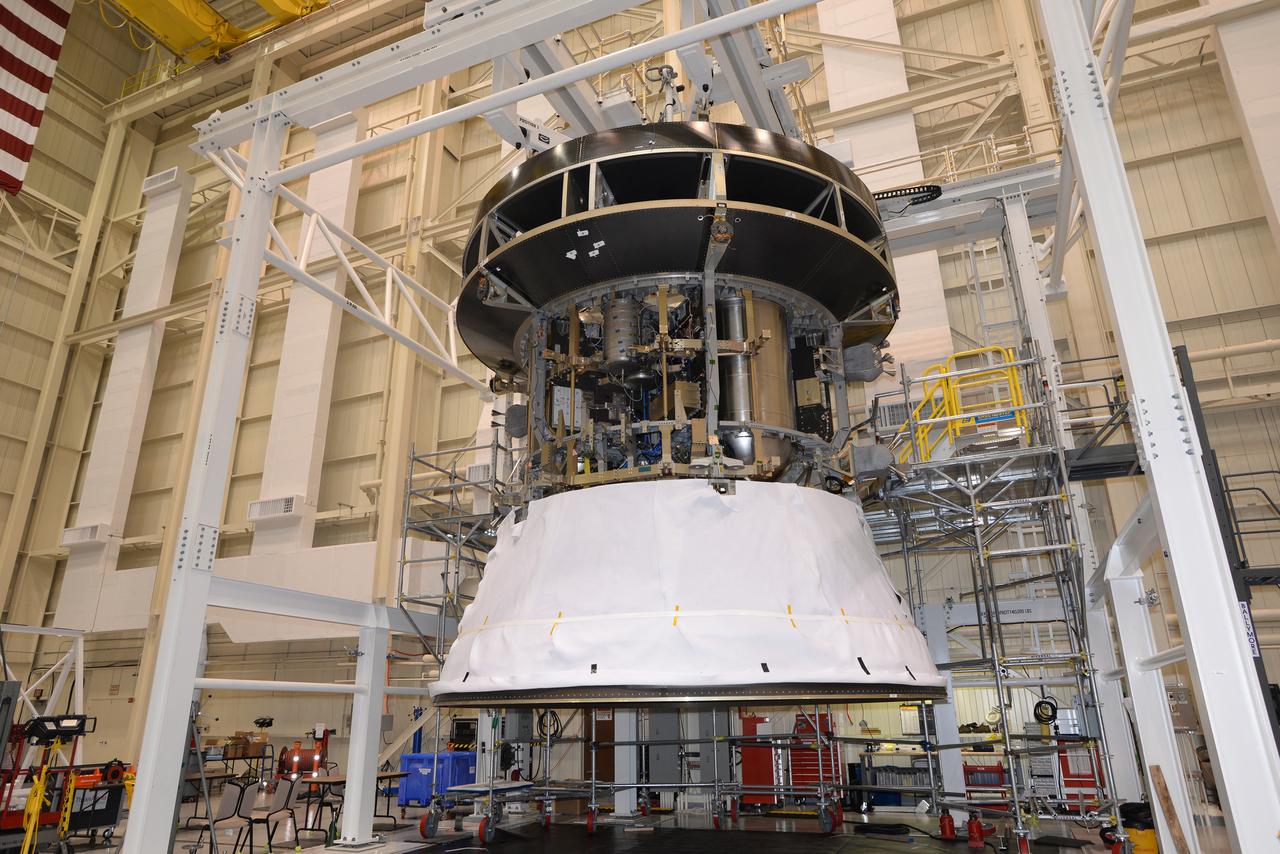
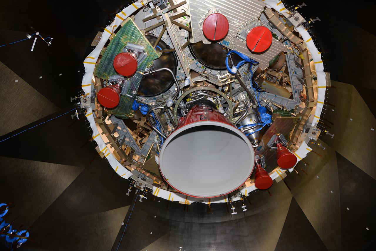
The European Service Module structural test model, shown on Jan. 23, 2016, is used for testing purposes before installing the real thing. It is as close to the flight version as possible while keeping costs and development time manageable. The structure and weight are the same, while mass equivalents stand in for electronics boxes not needed for the series of tests...The model was installed under a test version of the Crew Module Adapter, and sits on the Spacecraft Adapter that will attach Orion to its launch vehicle. This is the first time the European hardware has been physically connected to NASA’s elements...The service module will be shaken at NASA’s Plum Brook station in Sandusky, Ohio, USA, to recreate the vibrations of launch, as well as being subjected to acoustic and shock environments. Part of Batch image transfer from Flickr.
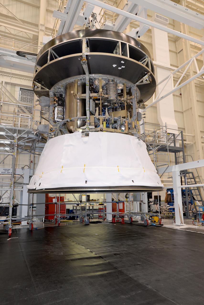
The European Service Module structural test model, shown on Jan. 23, 2016, is used for testing purposes before installing the real thing. It is as close to the flight version as possible while keeping costs and development time manageable. The structure and weight are the same, while mass equivalents stand in for electronics boxes not needed for the series of tests...The model was installed under a test version of the Crew Module Adapter, and sits on the Spacecraft Adapter that will attach Orion to its launch vehicle. This is the first time the European hardware has been physically connected to NASA’s elements...The service module will be shaken at NASA’s Plum Brook station in Sandusky, Ohio, USA, to recreate the vibrations of launch, as well as being subjected to acoustic and shock environments. Part of Batch image transfer from Flickr.
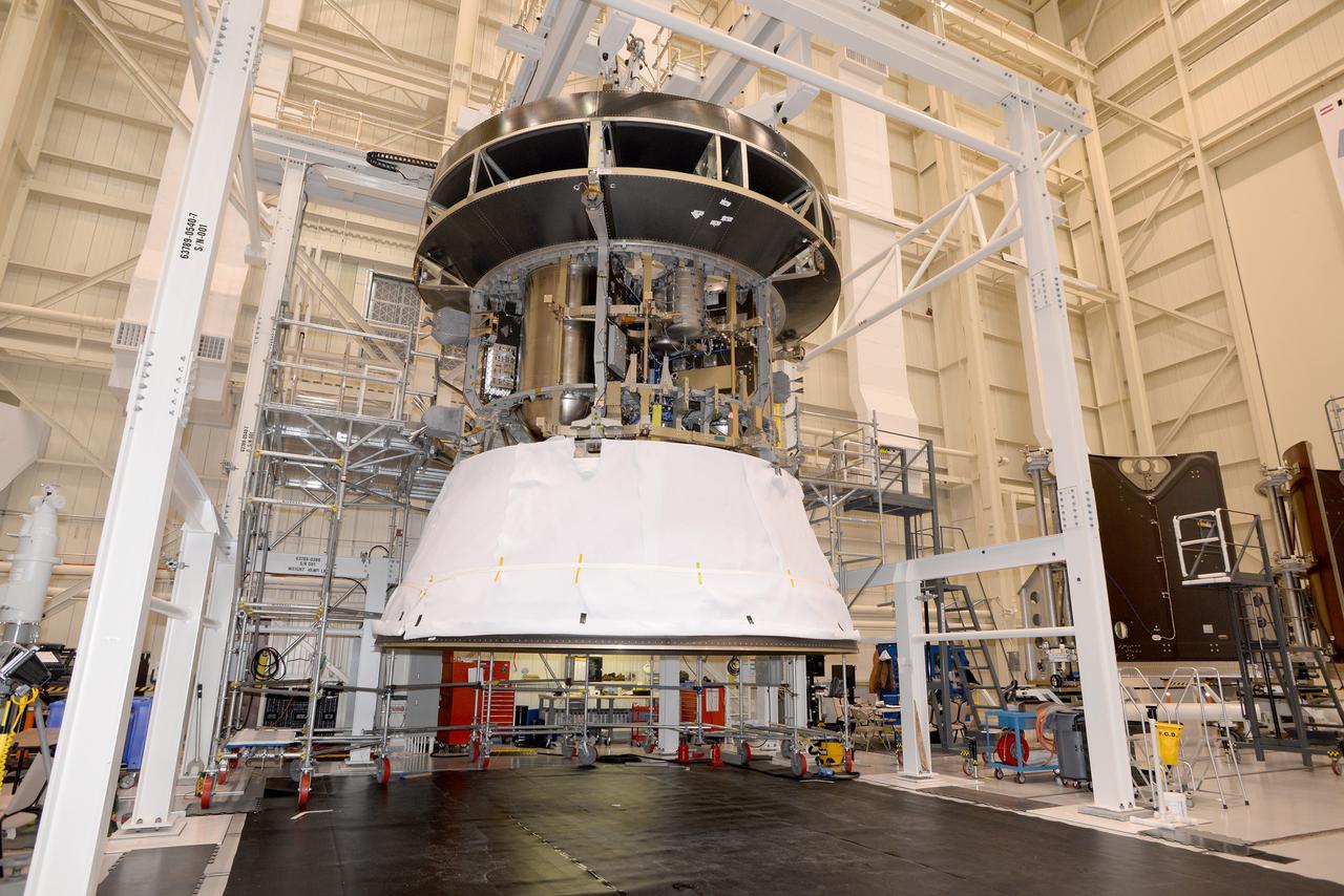
The European Service Module structural test model, shown on Jan. 23, 2016, is used for testing purposes before installing the real thing. It is as close to the flight version as possible while keeping costs and development time manageable. The structure and weight are the same, while mass equivalents stand in for electronics boxes not needed for the series of tests...The model was installed under a test version of the Crew Module Adapter, and sits on the Spacecraft Adapter that will attach Orion to its launch vehicle. This is the first time the European hardware has been physically connected to NASA’s elements...The service module will be shaken at NASA’s Plum Brook station in Sandusky, Ohio, USA, to recreate the vibrations of launch, as well as being subjected to acoustic and shock environments. Part of Batch image transfer from Flickr.
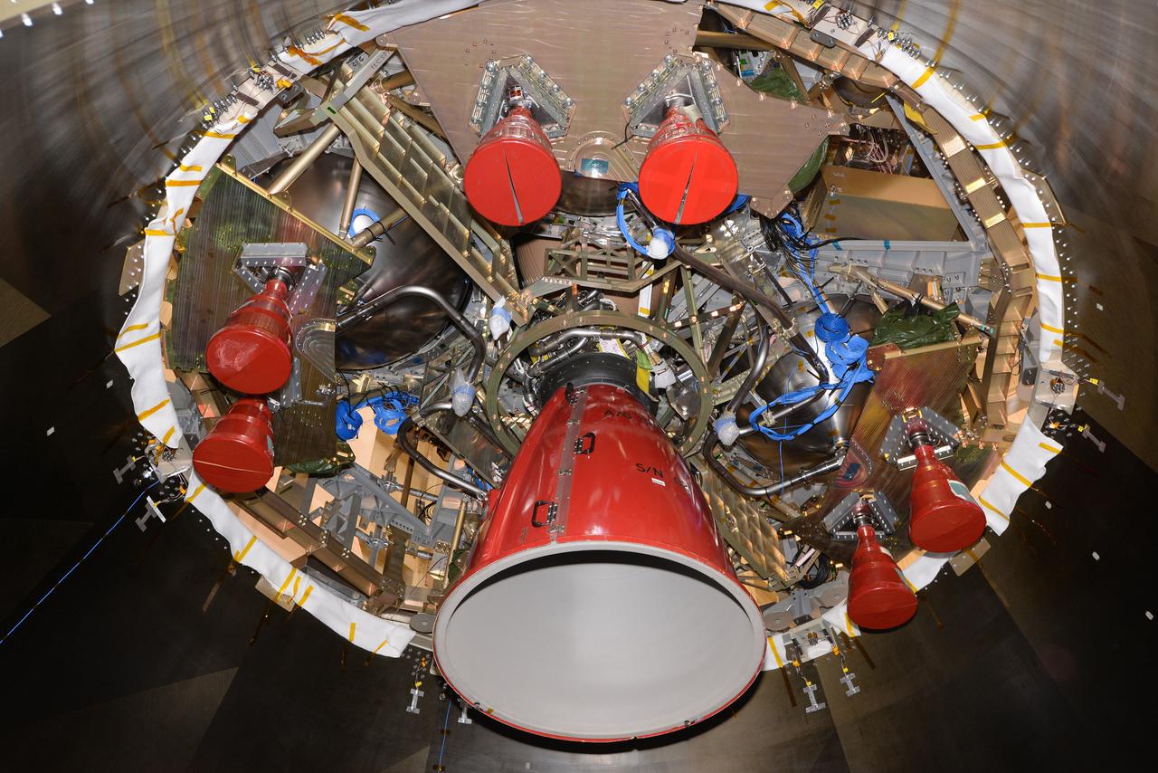
The European Service Module structural test model, shown on Jan. 23, 2016, is used for testing purposes before installing the real thing. It is as close to the flight version as possible while keeping costs and development time manageable. The structure and weight are the same, while mass equivalents stand in for electronics boxes not needed for the series of tests...The model was installed under a test version of the Crew Module Adapter, and sits on the Spacecraft Adapter that will attach Orion to its launch vehicle. This is the first time the European hardware has been physically connected to NASA’s elements...The service module will be shaken at NASA’s Plum Brook station in Sandusky, Ohio, USA, to recreate the vibrations of launch, as well as being subjected to acoustic and shock environments. Part of Batch image transfer from Flickr.
The European Service Module structural test model, shown on Jan. 23, 2016, is used for testing purposes before installing the real thing. It is as close to the flight version as possible while keeping costs and development time manageable. The structure and weight are the same, while mass equivalents stand in for electronics boxes not needed for the series of tests...The model was installed under a test version of the Crew Module Adapter, and sits on the Spacecraft Adapter that will attach Orion to its launch vehicle. This is the first time the European hardware has been physically connected to NASA’s elements...The service module will be shaken at NASA’s Plum Brook station in Sandusky, Ohio, USA, to recreate the vibrations of launch, as well as being subjected to acoustic and shock environments. Part of Batch image transfer from Flickr.

National Aeronautics and Space Administration (NASA) researcher John Carpenter inspects an aircraft model with a four-fan thrust reverser which would be studied in the 9- by 15-Foot Low Speed Wind Tunnel at the Lewis Research Center. Thrust reversers were introduced in the 1950s as a means for slowing high-speed jet aircraft during landing. Engineers sought to apply the technology to Vertical and Short Takeoff and Landing (VSTOL) aircraft in the 1970s. The new designs would have to take into account shorter landing areas, noise levels, and decreased thrust levels. A balance was needed between the thrust reverser’s efficiency, its noise generation, and the engine’s power setting. This model underwent a series of four tests in the 9- by 15-foot tunnel during April and May 1974. The model, with a high-wing configuration and no tail, was equipped with four thrust-reverser engines. The investigations included static internal aerodynamic tests on a single fan/reverser, wind tunnel isolated fan/reverser thrust tests, installation effects on a four-fan airplane model in a wind tunnel, and single reverser acoustic tests. The 9-by 15 was built inside the return leg of the 8- by 6-Foot Supersonic Wind Tunnel in 1968. The facility generates airspeeds from 0 to 175 miles per hour to evaluate the aerodynamic performance and acoustic characteristics of nozzles, inlets, and propellers, and investigate hot gas re-ingestion of advanced VSTOL concepts. John Carpenter was a technician in the Wind Tunnels Service Section of the Test Installations Division.
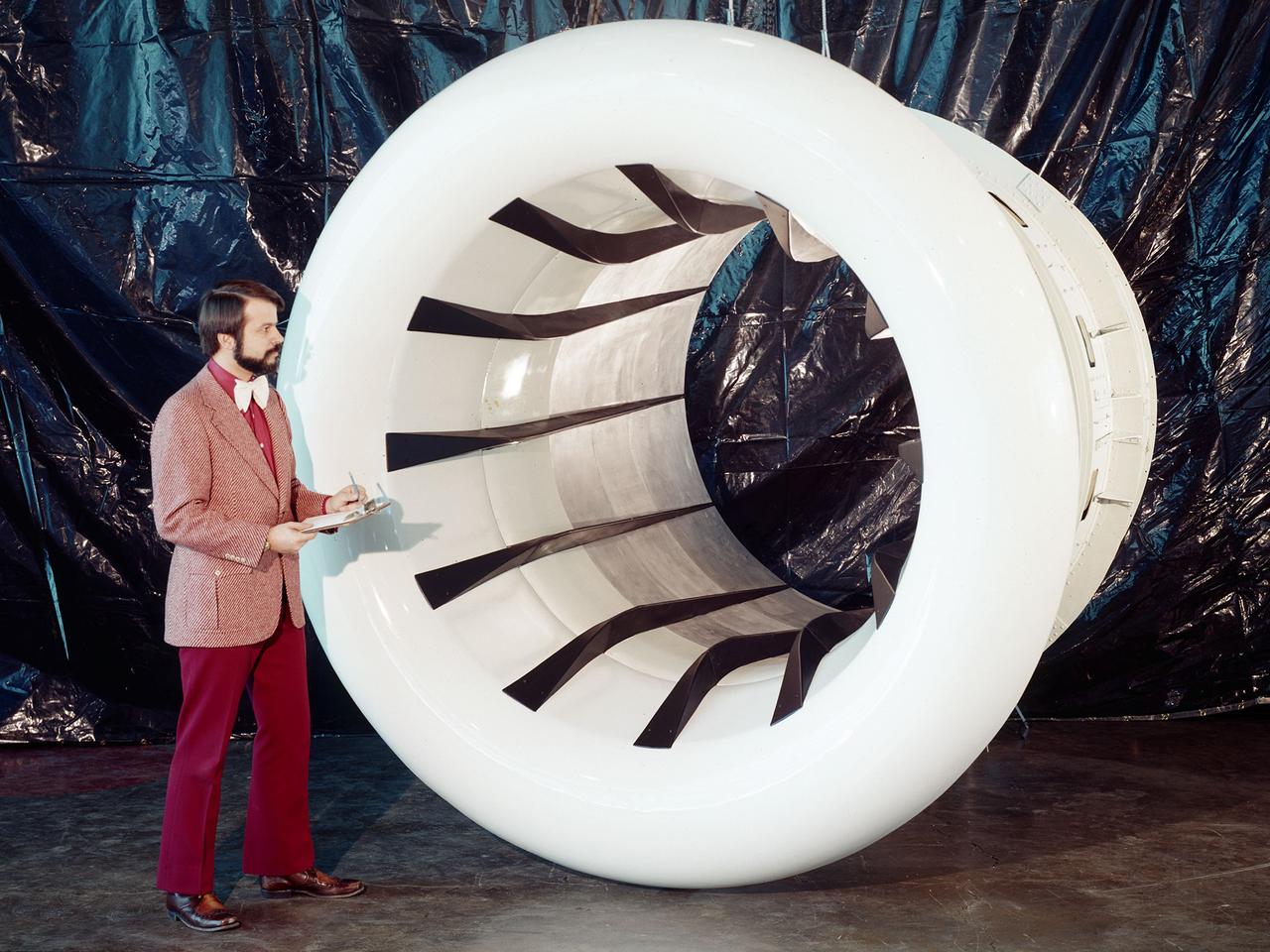
The Fan Noise Test Facility built at the Lewis Research Center to obtain far-field noise data for the National Aeronautics and Space Administration (NASA) and General Electric Quiet Engine Program. The engine incorporated existing noise reduction methods into an engine of similar power to those that propelled the Boeing 707 or McDonnell-Douglas DC-8 airliner. The new the low-bypass ratio turbofan engines of the 1960s were inherently quieter than their turbojet counterparts, researchers had a better grasp of the noise generation problem, and new acoustic technologies had emerged. Lewis contracted General Electric in 1969 to build and aerodynamically test three experimental engines with 72-inch diameter fans. The engines were then brought to Lewis and tested with an acoustically treated nacelle. This Fan Noise Test Facility was built off of the 10- by 10-Foot Supersonic Wind Tunnel’s Main Compressor and Drive Building. Lewis researchers were able to isolate the fan’s noise during these initial tests by removing the core of the engine. The Lewis test rig drove engines to takeoff tip speeds of 1160 feet per second. The facility was later used to test a series of full-scale model fans and fan noise suppressors to be used with the quiet engine. NASA researchers predicted low-speed single-stage fans without inlet guide vanes and with large spacing between rotors and stators would be quieter. General Electric modified a TF39 turbofan engine by removing the the outer protion of the fan and spacing the blade rows of the inner portion. The tests revealed that the untreated version of the engine generated less noise than was anticipated, and the acoustically treated nacelle substantially reduced engine noise.
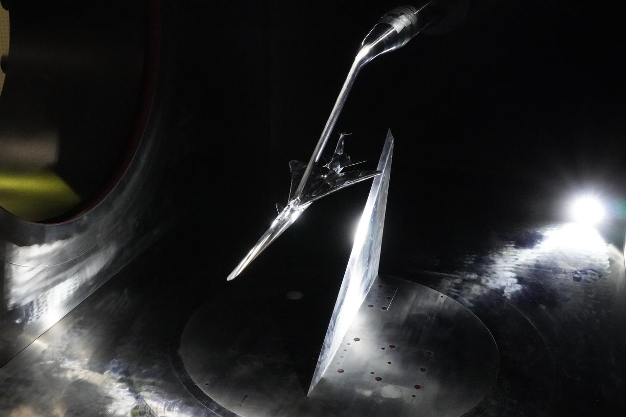
Here you see the X-59 scaled model inside the JAXA supersonic wind tunnel during critical tests related to sound predictions.
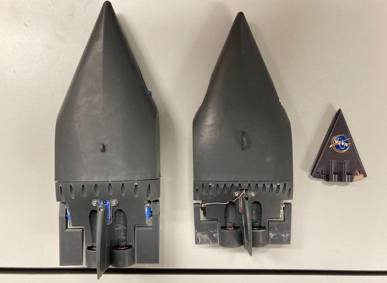
Two prototypes for a NASA mission concept called SWIM (short for Sensing With Independent Micro-swimmers) are arranged beside a much smaller nonfunctioning model representing the final envisioned size of the robot: about 5 inches (12 centimeters) long. The plastic prototypes were built at NASA's Jet Propulsion Laboratory in Southern California to demonstrate the feasibility of the concept, a swarm of dozens of self-propelled, cellphone-size robots exploring the waters of icy moons like Jupiter's Europa and Saturn's Enceladus. Delivered to the subsurface ocean by an ice-melting cryobot, the tiny robots would zoom away to look for chemical and temperature signals that could point to life. The prototypes were used in more that 20 rounds of underwater testing in a pair of tanks at JPL and in a competition swimming pool at Caltech in Pasadena. Relying on low-cost, commercially made motors and electronics, the robots are pushed along by two propellers and use two to four flaps for steering. The prototype in the center of the image weighs 3.7 pounds (1.7 kilograms) and is 14.5 inches (37 centimeters) long, 6 inches (15 centimeters) wide, and 2.5 inches (6.5 centimeters) tall, with a volume of 104 cubic inches (1.7 liters). The upgraded prototype at left is slightly bigger: 16.5 inches (42 centimeters) long, 3 inches (7.5 centimeters) tall, with a weight of 5 pounds (2.3 kilograms) and a volume of 140 cubic inches (2.3 liters). In pool tests, the prototype at left demonstrated controlled maneuvering, the ability to stay on and correct its course, and a back-and-forth "lawnmower" exploration pattern. It managed all of this autonomously, without the team's direct intervention. The robot even spelled out "J-P-L." As conceived for spaceflight and represented by the model at right, the robots would have dimensions about three times smaller than these prototypes – tiny compared to existing remotely operated and autonomous underwater scientific vehicles. The swimmers would feature miniaturized, purpose-built parts and employ a novel wireless underwater acoustic communication system for transmitting data and triangulating their positions. Several years more of work would be needed to make such an advanced concept ready for spaceflight. Led by JPL, SWIM development took place from spring 2021 to fall 2024. The project was supported by Phase I and II funding from NASA's Innovative Advanced Concepts program under the agency's Space Technology Mission Directorate. JPL is managed for NASA by Caltech in Pasadena, California. https://photojournal.jpl.nasa.gov/catalog/PIA26425
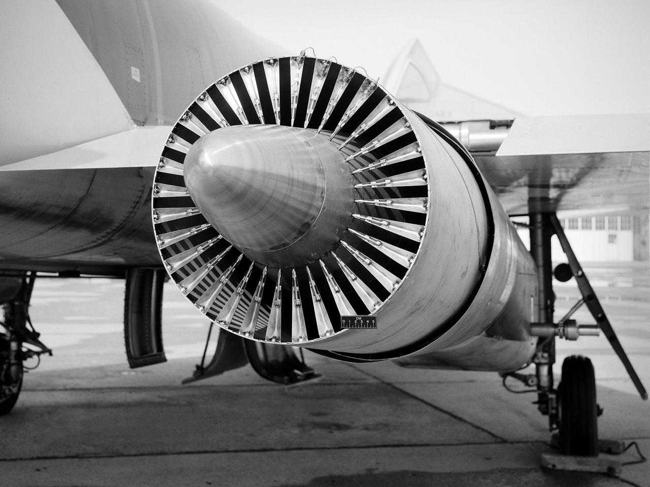
National Aeronautics and Space Administration (NASA) Convair F-106B Delta Dart with a 32-spoke nozzle installed on its General Electric J85 test engine. Lewis acquired a Delta Dart fighter in 1966 to study the components for propulsion systems that could be applied to supersonic transport aircraft at transonic speeds. The F-106B was modified with two General Electric J85-13 engines under its wings to study these components. The original test plan was expanded to include the study of boattail drag, noise reduction, and inlets. From February to July 1971 the modified F-106B was used to study different ejector nozzles. Researchers conducted both acoustic and aerodynamic tests on the ground and in flight. Several models were created to test different suppression methods. NASA Lewis’ conical nozzle was used as the baseline configuration. Flightline and sideline microphones were set up on the ground. The F-106B would idle its own engine and buzz the recording station from an altitude of 300 feet at Mach 0.4 with the test engines firing. Researchers found that the suppression of the perceived noise level was usually lower during flight than the researchers had statistically predicted. The 64 and 32-spoke nozzles performed well in actual flight, but the others nozzles tended to negatively affect the engine’s performance. Different speeds or angles- -of-attack sometimes changed the noise levels. In the end, no general conclusions could be applied to all the nozzles.
Brent Miller, of the V/STOL and Noise Division at the National Aeronautics and Space Administration (NASA) Lewis Research Center, poses with a sonic inlet for the NASA Quiet Engine Program. NASA Lewis had first investigated methods for reducing aircraft engine noise in the mid-1950s. Those efforts were resurrected and expanded in the late 1960s. The researchers found that the use of a sonic, or high-throat-Mach-number, inlet was effective at reducing the noise from the engine inlet. The device accelerated the inlet air to near-sonic speeds which kept the forward moving sound waves away from the inlet. The device also deflected the sound waves into the wall to further reduce the noise. NASA Lewis researchers tested models of the sonic inlet in their 9- by 15-Foot Low Speed Wind Tunnel. They found that the general level of aerodynamic performance was good. The tests during simulated takeoff and landing conditions demonstrated the sonic inlet’s ability to provide good aerodynamic and acoustic performance The researchers then successfully tested two full-scale sonic inlet designs, one from Pratt and Whitney and one from General Electric, with fans. A full-scale engine was installed on a thrust stand to determine the sonic inlet’s effect on the engine’s performance. The amount of noise reduction increased as the inlet flow velocity increased, but the full-scale tests did not produce as great a decrease in noise as the earlier small-scale tests.