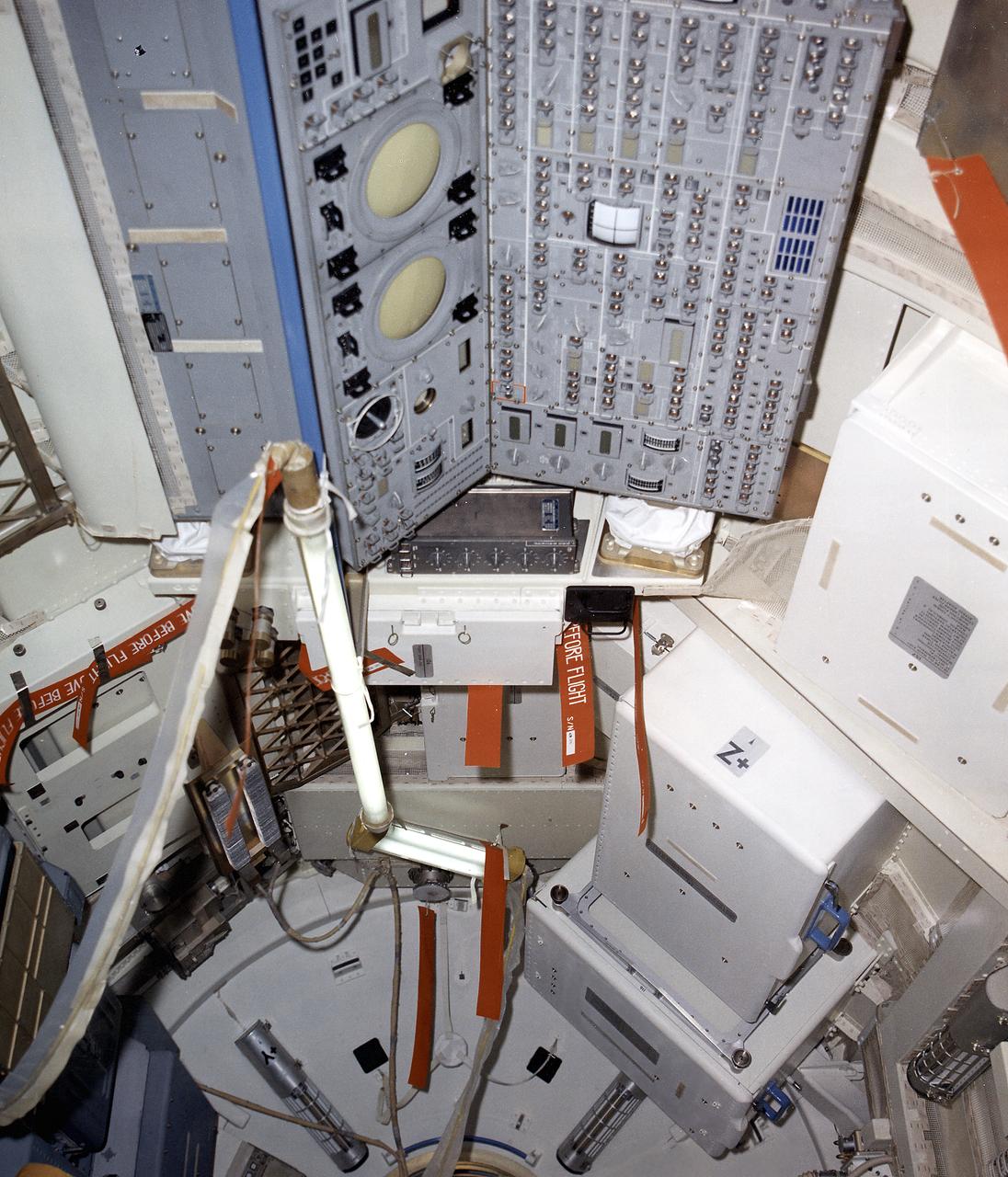
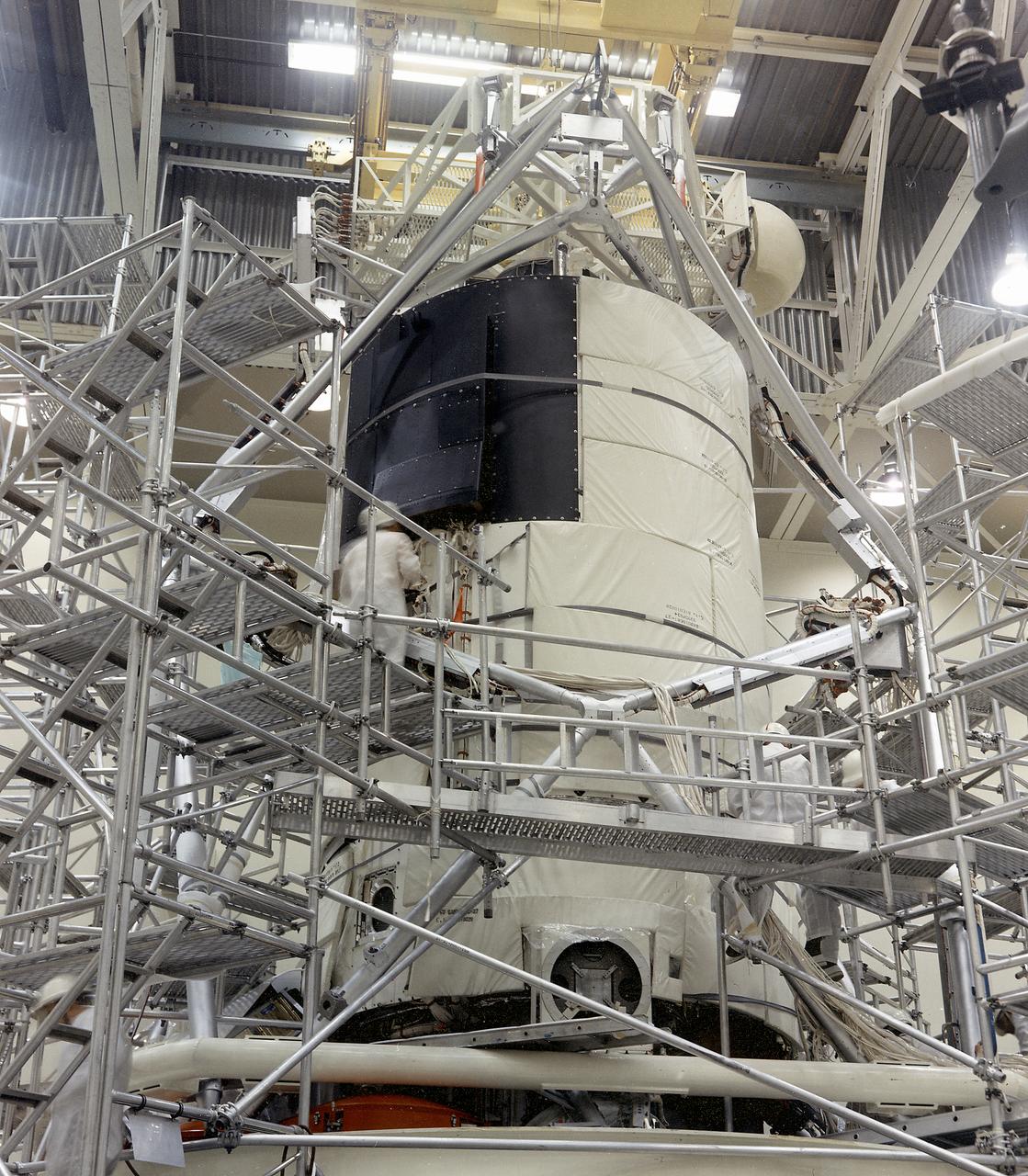
This December 1971 photograph shows the internal configuration of Skylab's Multiple Docking Adapter (MDA) as it appeared during the Crew Compartment and Function Review at the Martin-Marietta Corporation's Space Center facility in Denver, Colorado. At left is the control and display console for the Apollo Telescope Mount. Designed and manufactured by the Marshall Space Flight Center, the MDA housed a number of experiment control and stowage units and provided a docking port for the Apollo Command Module.
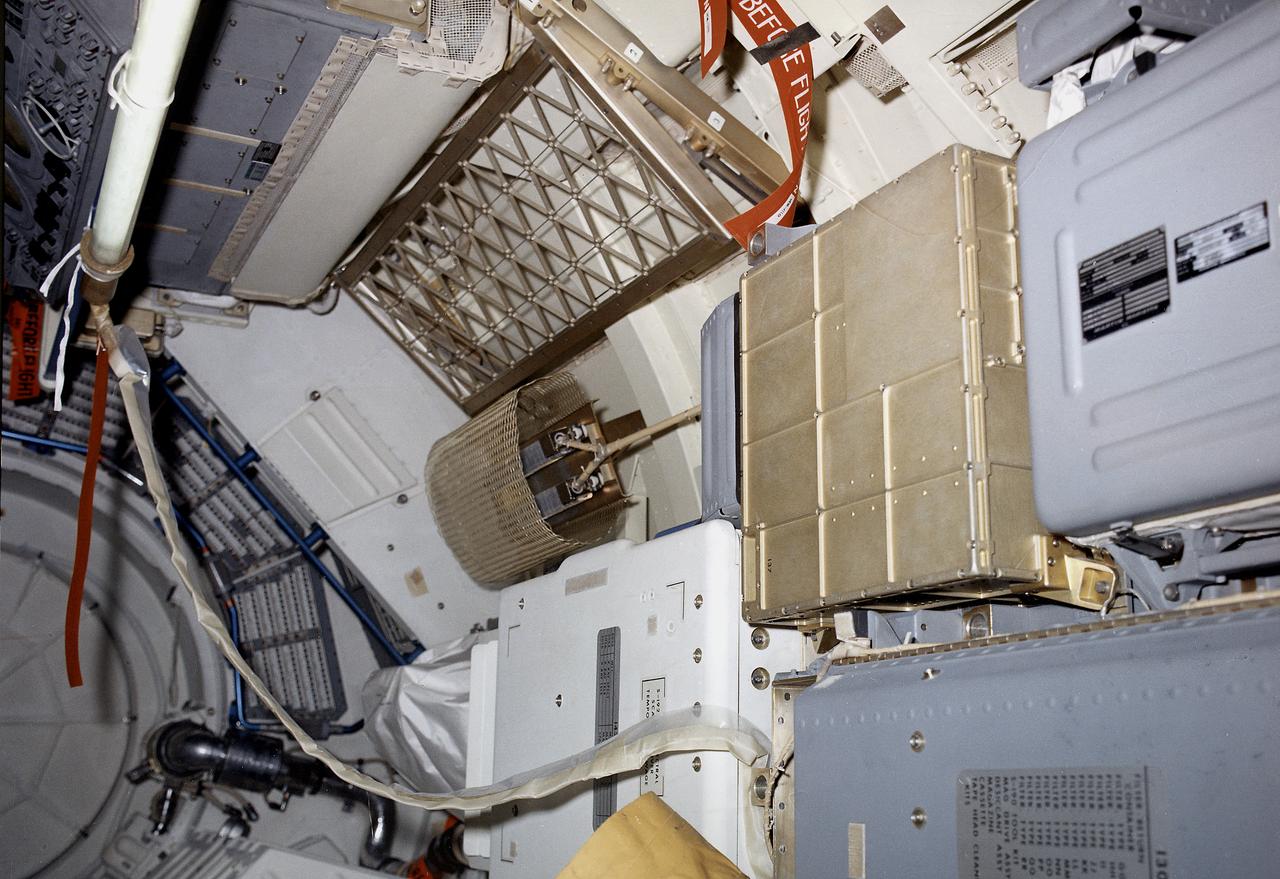
The Multiple Docking Adapter (MDA), designed and constructed under the direction of the Marshall Space Flight Center, was one of four principal sections comprising Skylab. The MDA provided the means by which the Command and Service Modules attached to the Skylab, enabling the crews to enter and work in it. Also included in the MDA was a control and display console for the Apollo Telescope Mount. This image shows an interior view of the MDA.

Jeff Greulich, DynCorp life support technician, adjusts a prototype helmet on pilot Craig Bomben at NASA Dryden Flight Research Center, Edwards, Calif. Built by Gentex Corp., Carbondale, Pa., the helmet was evaluated by five NASA pilots during the summer and fall of 2002. The objective was to obtain data on helmet fit, comfort and functionality. The inner helmet of the modular system is fitted to the individual crewmember. The outer helmet features a fully integrated spectral mounted helmet display and a binocular helmet mounted display. The helmet will be adaptable to all flying platforms. The Dryden evaluation was overseen by the Center's Life Support office. Assessments have taken place during normal proficiency flights and some air-to-air combat maneuvering. Evaluation platforms included the F-18, B-52 and C-12. The prototype helmet is being developed by the Naval Air Science and Technology Office and the Aircrew Systems Program Office, Patuxent River, Md.
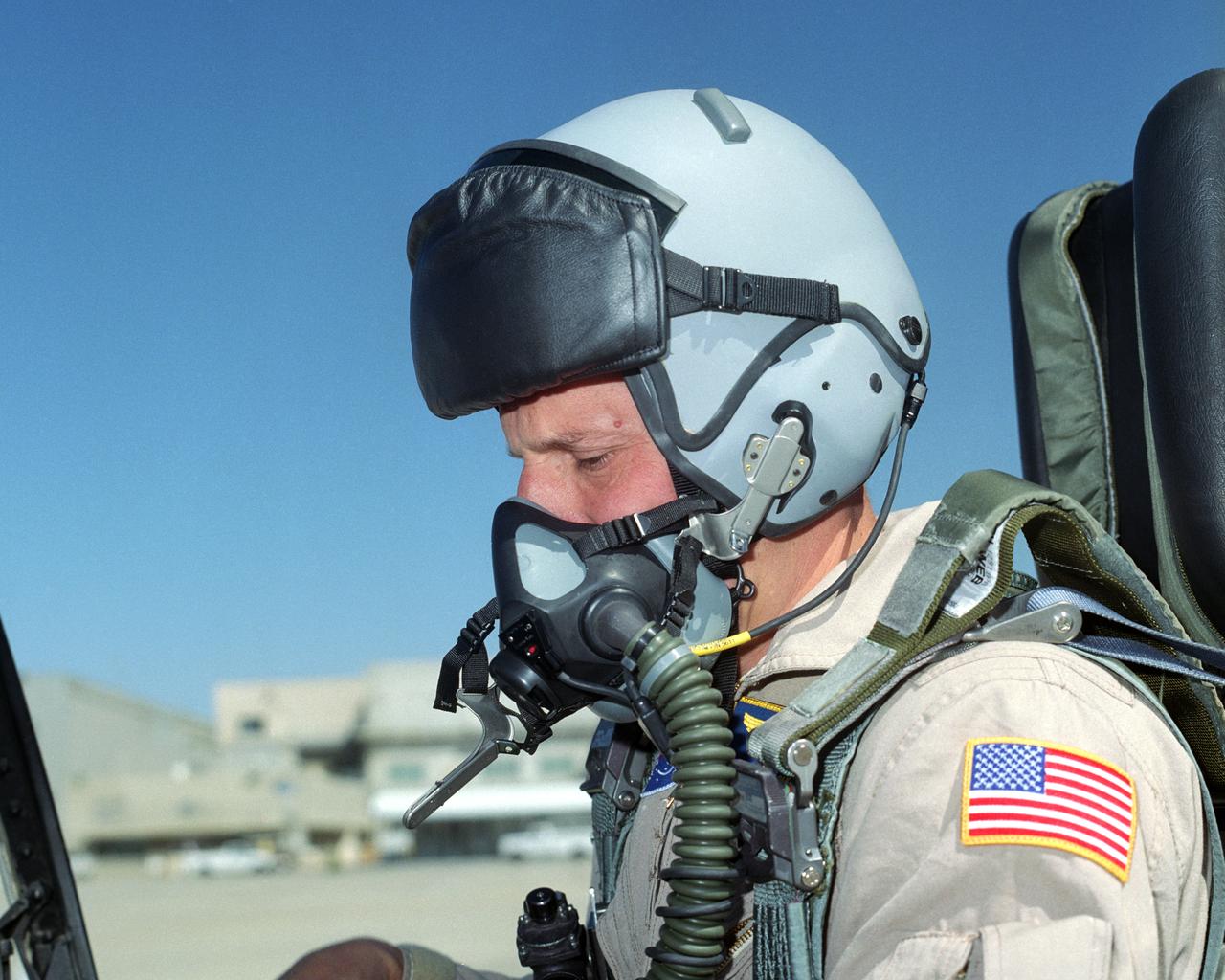
Research pilots from the NASA Dryden Flight Research Center, Edwards, Calif., tested a prototype two-part helmet. Built by Gentex Corp., Carbondale, Pa., the helmet was evaluated by five NASA pilots during the summer and fall of 2002. The objective was to obtain data on helmet fit, comfort and functionality. The inner helmet of the modular system is fitted to the individual crewmember. The outer helmet features a fully integrated spectral mounted helmet display and a binocular helmet mounted display. The helmet will be adaptable to all flying platforms. The Dryden evaluation was overseen by the Center's Life Support office. Assessments have taken place during normal proficiency flights and some air-to-air combat maneuvering. Evaluation platforms included the F-18, B-52 and C-12. The prototype helmet is being developed by the Naval Air Science and Technology Office and the Aircrew Systems Program Office, Patuxent River, Md.
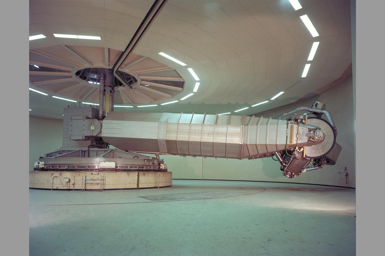
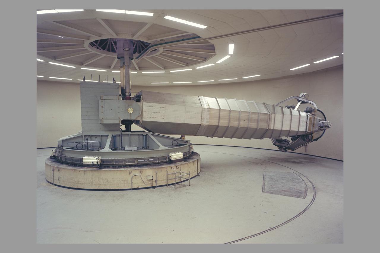
N-243 Flight and Guidance Centrifuge: Is used for spacecraft mission simulations and is adaptable to two configurations. Configuration 1: The cab will accommodate a three-man crew for space mission research. The accelerations and rates are intended to be smoothly applicable at very low value so the navigation and guidance procedures using a high-accuracy, out-the window display may be simulated. Configuration 2: The simulator can use a one-man cab for human tolerance studies and performance testing. Atmosphere and tempertaure can be varied as stress inducements. This simlator is operated closed-loop with digital or analog computation. It is currently man-rated for 3.5g maximum.
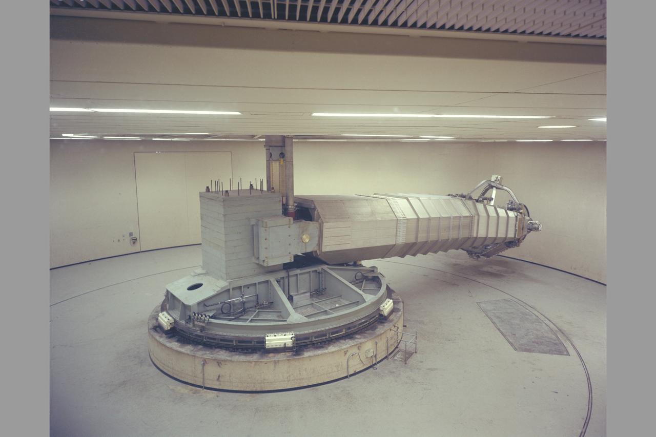
N-243 Flight and Guidance Centrifuge: Is used for spacecraft mission simulations and is adaptable to two configurations. Configuration 1: The cab will accommodate a three-man crew for space mission research. The accelerations and rates are intended to be smoothly applicable at very low value so the navigation and guidance procedures using a high-accuracy, out-the window display may be simulated. Configuration 2: The simulator can use a one-man cab for human tolerance studies and performance testing. Atmosphere and tempertaure can be varied as stress inducements. This simlator is operated closed-loop with digital or analog computation. It is currently man-rated for 3.5g maximum.
N-243 Flight and Guidance Centrifuge: Is used for spacecraft mission simulations and is adaptable to two configurations. Configuration 1: The cab will accommodate a three-man crew for space mission research. The accelerations and rates are intended to be smoothly applicable at very low value so the navigation and guidance procedures using a high-accuracy, out-the window display may be simulated. Configuration 2: The simulator can use a one-man cab for human tolerance studies and performance testing. Atmosphere and tempertaure can be varied as stress inducements. This simlator is operated closed-loop with digital or analog computation. It is currently man-rated for 3.5g maximum.

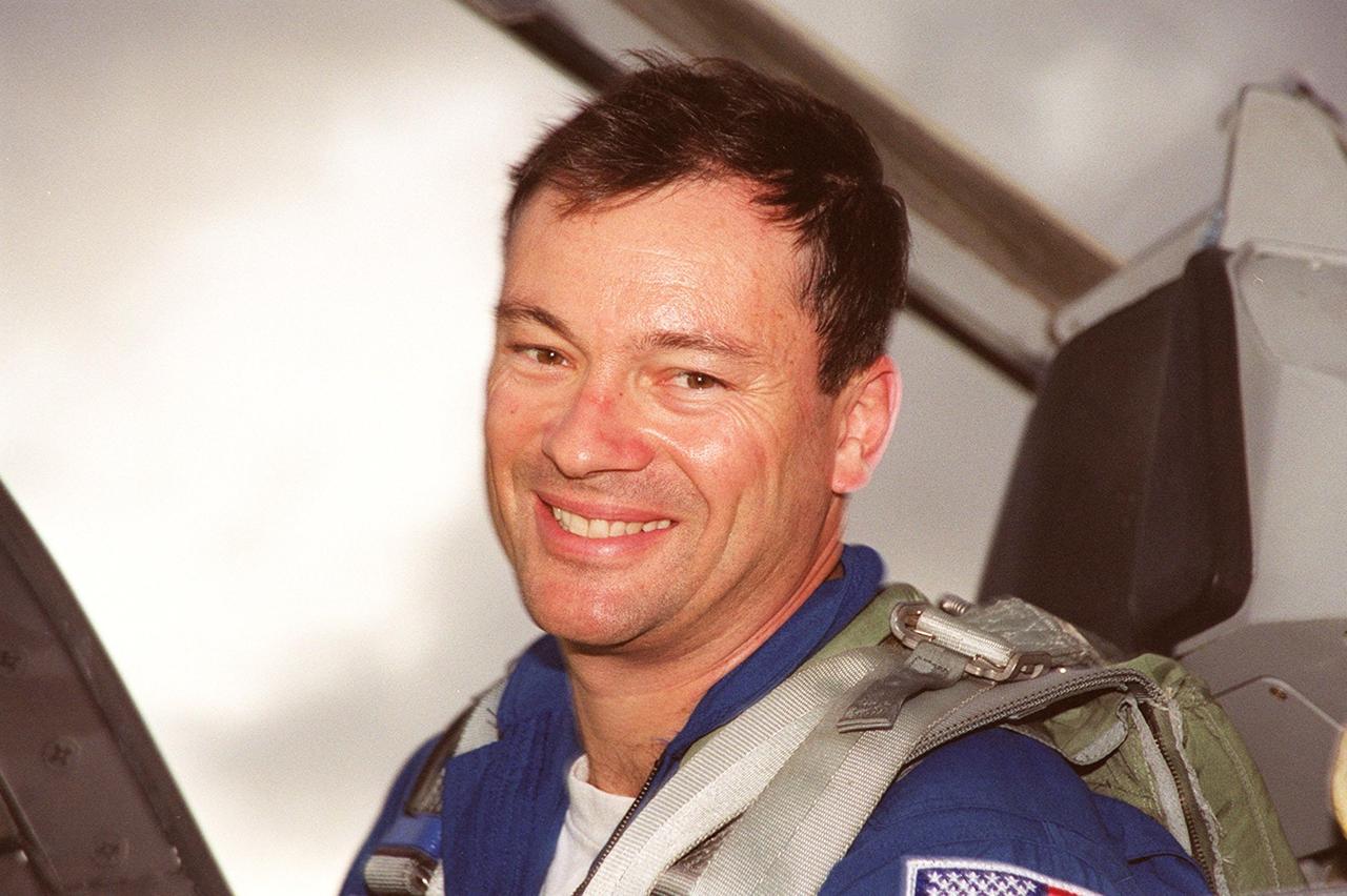
KENNEDY SPACE CENTER, FLA. -- Upon arriving at KSC aboard a T-38 jet aircraft, STS-92 Mission Specialist Michael E. Lopez-Alegria displays with a smile his eagerness for launch. He and other crew members Commander Brian Duffy, Pilot Pamela Ann Melroy and Mission Specialists Koichi Wakata of Japan, Leroy Chiao, Peter J.K. “Jeff” Wisoff and William S. McArthur Jr. later talked to a waiting group of media at the Shuttle Landing Facility. The mission is the fifth flight for the construction of the International Space Station. The payload includes the Integrated Truss Structure Z-1 and the third Pressurized Mating Adapter. During the 11-day mission, four extravehicular activities (EVAs), or space walks, are planned
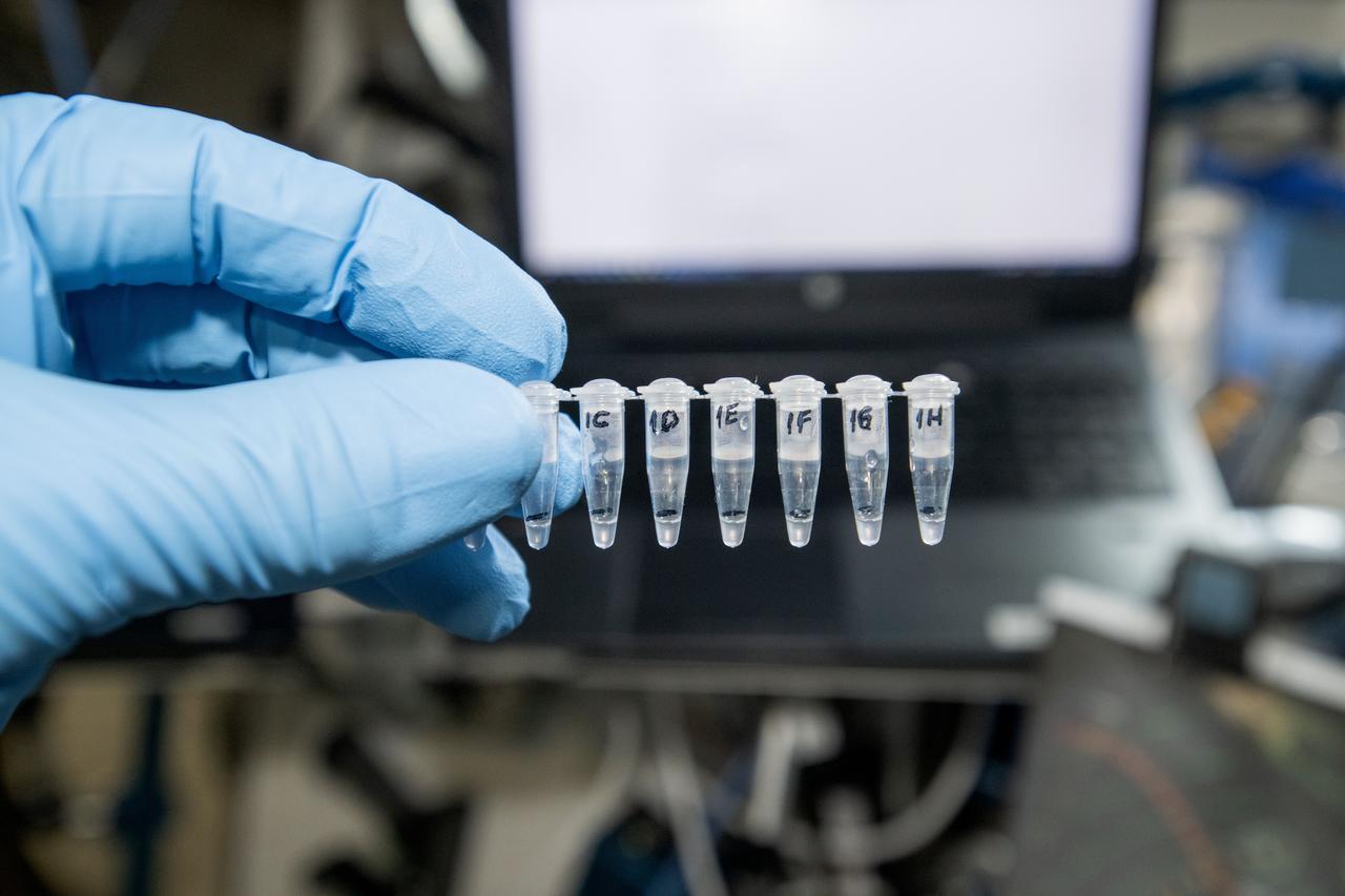
iss072e010035 (Oct. 12, 2024) --- NASA astronaut and Expedition 72 Flight Engineer Don Pettit displays Genes In Space-11 samples validating on-orbit Nucleic Acid Sequenced Based Amplification (NASBA), a novel technique to detect specific RNA sequences that can be applied to studying crucial biological processes, such as viral infection, genomic damage, or gene expression during spaceflight. Genes in Space-11 studies how spaceflight may activate retrotransposons, which are DNA fragments that copy and paste themselves throughout a genome, leading to cancer and other diseases. This investigation tests methods for detecting and measuring retrotransposons that may be adapted to detect other RNAs, including those of viruses that cause illness. Understanding the behavior of retrotransposons in microgravity may shed light on the genetic risks, including cancer, from space travel and support development of ways to protect astronauts during missions.
KENNEDY SPACE CENTER, FLA. -- Upon arriving at KSC aboard a T-38 jet aircraft, STS-92 Mission Specialist Michael E. Lopez-Alegria displays with a smile his eagerness for launch. He and other crew members Commander Brian Duffy, Pilot Pamela Ann Melroy and Mission Specialists Koichi Wakata of Japan, Leroy Chiao, Peter J.K. “Jeff” Wisoff and William S. McArthur Jr. later talked to a waiting group of media at the Shuttle Landing Facility. The mission is the fifth flight for the construction of the International Space Station. The payload includes the Integrated Truss Structure Z-1 and the third Pressurized Mating Adapter. During the 11-day mission, four extravehicular activities (EVAs), or space walks, are planned
This photograph shows the flight article of the Airlock Module (AM)/Multiple Docking Adapter (MDA) assembly being readied for testing in a clean room at the McDornell Douglas Plant in St. Louis, Missouri. Although the AM and the MDA were separate entities, they were in many respects simply two components of a single module. The AM enabled crew members to conduct extravehicular activities outside Skylab as required for experiment support. Oxygen and nitrogen storage tanks needed for Skylab's life support system were mounted on the external truss work of the AM. Major components in the AM included Skylab's electric power control and distribution station, environmental control system, communication system, and data handling and recording systems. The MDA, forward of the AM, provided docking facilities for the Command and Service Module. It also accommodated several experiment systems, among them the Earth Resource Experiment Package, the materials processing facility, and the control and display console needed for the Apollo Telescope Mount solar astronomy studies. The AM was built by McDonnell Douglas and the MDA was built by Martin Marietta. The Marshall Space Flight Center was responsible for the design and development of the Skylab hardware and experiment management.
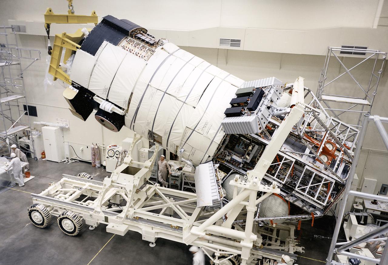
This photograph shows the flight article of the mated Airlock Module (AM) and Multiple Docking Adapter (MDA) being lowering into horizontal position on a transporter. Although the AM and the MDA were separate entities, they were in many respects simply two components of a single module. The AM enabled crew members to conduct extravehicular activities outside Skylab as required for experiment support. Oxygen and nitrogen storage tanks needed for Skylab's life support system were mounted on the external truss work of the AM. Major components in the AM included Skylab's electric power control and distribution station, environmental control system, communication system, and data handling and recording systems. The MDA, forward of the AM, provided docking facilities for the Command and Service Module. It also accommodated several experiment systems, among them the Earth Resource Experiment Package, the materials processing facility, and the control and display console needed for the Apollo Telescope Mount solar astronomy studies. The AM was built by McDornell Douglas and the MDA was built by Martin Marietta. The Marshall Space Flight Center was responsible for the design and development of the Skylab hardware and experiment management.
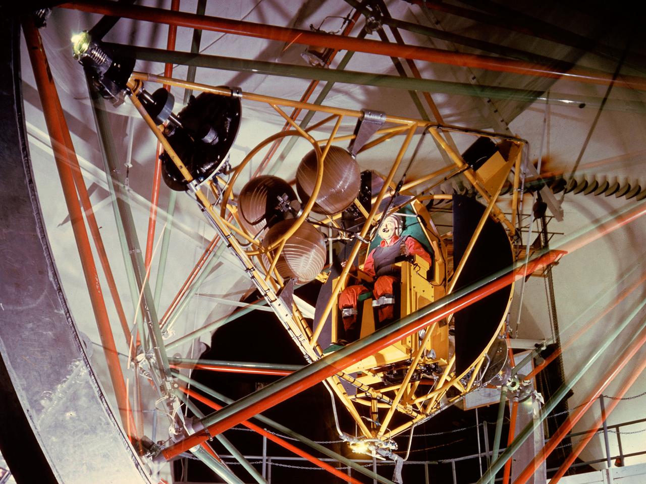
National Aeronautics and Space Administration (NASA) pilot Joe Algranti tests the Multi-Axis Space Test Inertia Facility (MASTIF) inside the Altitude Wind Tunnel while researcher Robert Miller looks on. The MASTIF was a three-axis rig with a pilot’s chair mounted in the center to train Project Mercury pilots to bring a spinning spacecraft under control. An astronaut was secured in a foam couch in the center of the rig. The rig then spun on three axes from 2 to 50 rotations per minute. Small nitrogen gas thrusters were used by the astronauts to bring the MASTIF under control. The device was originally designed in early 1959 without the chair and controllers. It was used by Lewis researchers to determine if the Lewis-designed autopilot system could rectify the capsule’s attitude following separation. If the control system failed to work properly, the heatshield would be out of place and the spacecraft would burn up during reentry. The system was flight tested during the September 1959 launch of the Lewis-assembled Big Joe capsule. The MASTIF was adapted in late 1959 for the astronaut training. NASA engineers added a pilot’s chair, a hand controller, and an instrument display to the MASTIF in order familiarize the astronauts with the sensations of an out-of-control spacecraft. NASA Lewis researcher James Useller and Algranti perfected and calibrated the MASTIF in the fall of 1959. In February and March 1960, the seven Project Mercury astronauts traveled to Cleveland to train on the MASTIF.
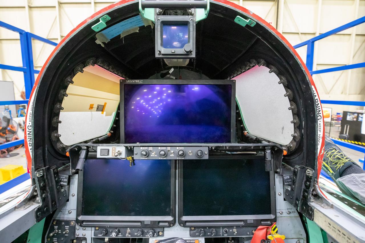
This image shows the forward view of the X-59’s cockpit with the canopy open. The aircraft will not have a forward-facing window and will use an eXternal Vision System (XVS) made up of a high definition 4K monitor (located in the center) and two monitors below to help the pilots safely fly through the skies.
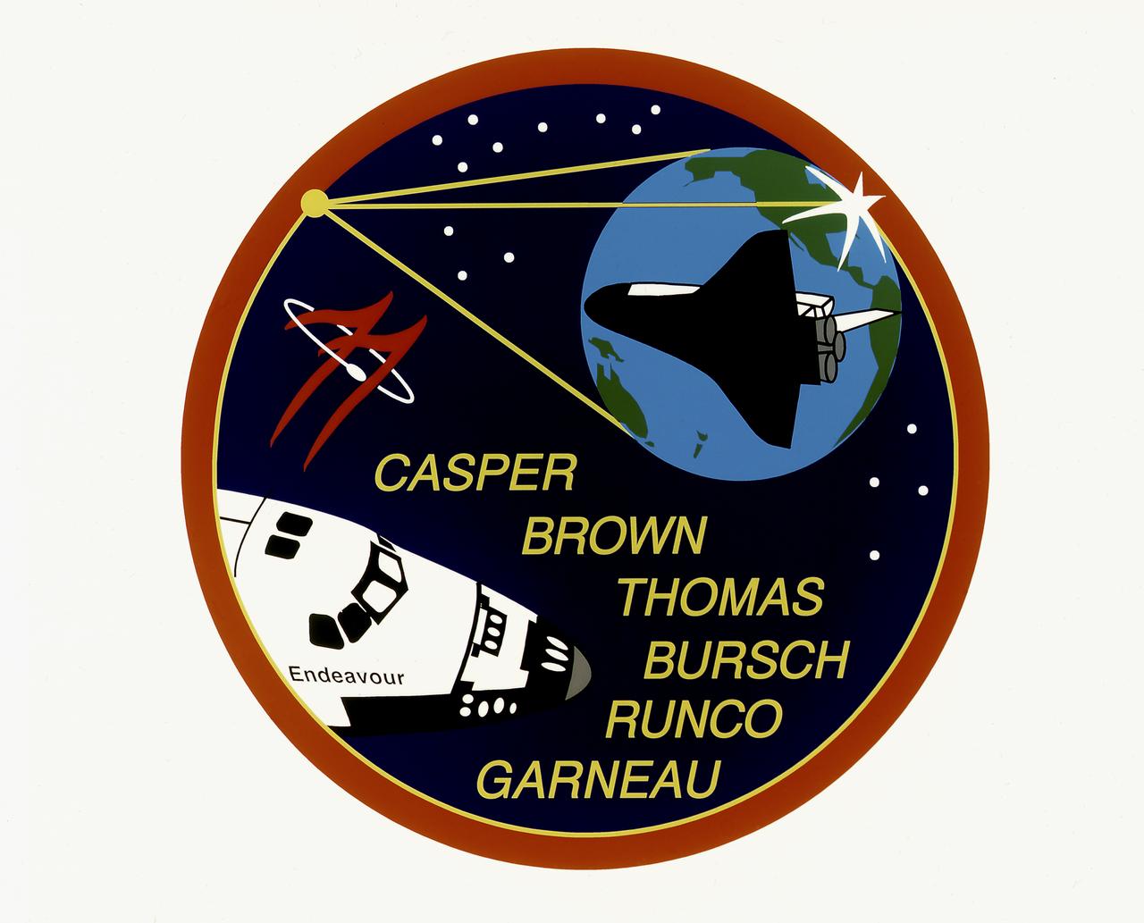
The STS-77 crew patch displays the Shuttle Endeavour in the lower left and its reflection within the tripod and concave parabolic mirror of the SPARTAN Inflatable Antenna Experiment (IAE). The center leg of the tripod also delineates the top of the Spacehab's shape, the rest of which is outlined in gold just inside the red perimeter. The Spacehab was carried in the payload bay and housed the Commercial Float Zone Furnace (CFZF). Also depicted within the confines of the IAE mirror are the mission's rendezvous operations with the Passive Aerodynamically-Stabilized Magnetically-Damped satellite (PAM/STU) appears as a bright six-pointed star-like reflection of the sun on the edge of the mirror with Endeavour in position to track it. The sunlight on the mirror's edge, which also appears as an orbital sunset, is located over Goddard Space Flight Center, the development facility for the SPARTAN/IAE and Technology Experiments Advancing Missions in Space (TEAMS) experiments. The reflection of the Earth is oriented to show the individual countries of the crew as well as the ocean which Captain Cook explored in the original Endeavour. The mission number 77 is featured as twin stylized chevrons and an orbiting satellite as adapted from NASA's logo. The stars at the top are arranged as seen in the northern sky in the vicinity of the constellation Ursa Minor. The field of 11 stars represents both the TEAMS cluster of experiments (the four antennae of GPS Attitude and Navigation Experiment (GANE), the single canister of Liquid Metal Thermal Experiment (LMTE), the three canisters of Vented Tank Resupply Experiment (VTRE), and the three canisters of PAM/STU) and the 11th flight of Endeavour. The constellation at the right shows the fourth flight of Spacehab Experiments.
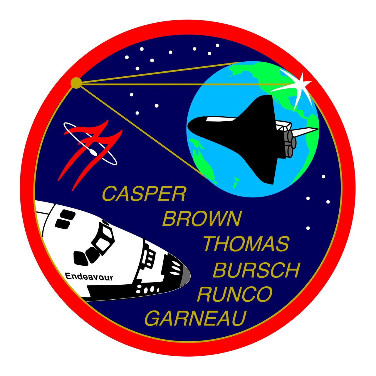
STS077-S-001 (February 1996) --- The STS-77 crew patch, designed by the crew members, displays the space shuttle Endeavour the lower left and its reflection within the tripod and concave parabolic mirror of the Shuttle Pointed Autonomous Research Tool for Astronomy (SPARTAN) Inflatable Antenna Experiment (IAE). The center leg of the tripod also delineates the top of the Spacehab?s shape, the rest of which is outlined in gold just inside the red perimeter. The Spacehab is carried in the payload bay and houses the Commercial Float Zone Furnace (CFZF) and Space Experiment Facility (SEF) experiments. Also depicted within the confines the IAE mirror are the mission?s rendezvous operations with the Passive Aerodynamically Stabilized Magnetically Damped Satellite/Satellite Test Unit (PAM/STU) satellite and a reflection of Earth. The PAM/STU satellite appears as a bright six-pointed star-like reflection of the sun on the edge of the mirror with the space shuttle Endeavour in position to track it. The sunglint on the mirror?s edge, which also appears as an orbital sunset, is located over Goddard Space Flight Center (GSFC), the development facility for the SPARTAN/IAE and Technology Experiments Advancing Missions in Space (TEAMS) experiments. The reflection of Earth is oriented to show the individual countries of the crew as well as the ocean which Captain Cook explored in the original Endeavour. The mission number ?77? is featured as twin stylized chevrons and an orbiting satellite as adapted from NASA?s logo. The stars at the top are arranged as seen in the northern sky in the vicinity of the constellation Ursa Minor. The field of 11 stars represents both the TEAMS cluster of experiments (the four antennae of Global Positioning System Attitude and Navigation Experiment (GANE), the single canister of Liquid Metal Thermal Experiment (LMTE), the three canisters of Vented Tank Resupply Experiment (VTRE), and the canisters of PAM/STU, and the 11th flight of the Endeavour. The constellation at the right shows the four stars of the Southern Cross for the fourth flight of Spacehab. The NASA insignia design for space shuttle flights is reserved for use by the astronauts and for other official use as the NASA Administrator may authorize. Public availability has been approved only in the forms of illustrations by the various news media. When and if there is any change in this policy, which is not anticipated, the change will be publicly announced. Photo credit: NASA