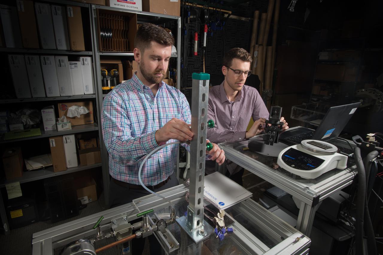
Advanced Thermal Management, High Power Density Core, Advanced Air Transport Technology,
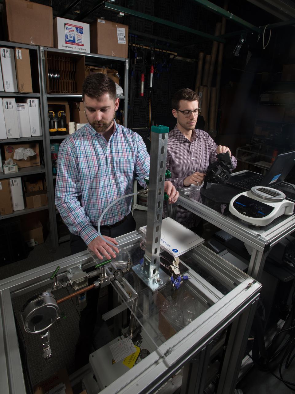
Advanced Thermal Management, High Power Density Core, Advanced Air Transport Technology,

Title: W-8 Fan Acoustic Casing Treatment Test on the Source Diagnostic Test Rotor Alone Hardware Program: Advanced Air Vehicles Program (AAVP) Project: Advanced Air Transport Technology (AATT) Sub-project: Aircraft Noise Reduction (ANR) Weekly Highlight: · Acoustic Casing Treatment Testing Completed in the W-8 Single Stage Axial Compressor Facility: Testing of Acoustic Casing Treatments on the Source Diagnostic Test (SDT) rotor alone hardware which had begun in early January was completed on Thursday, February 16th. Four different over-the-rotor acoustic casing treatment concepts were tested along with two baseline configurations. Testing included steady-aerodynamic measurements of fan performance, hotfilm turbulence measurements, and inlet acoustic measurements with an in-duct array. These measurements will be used to assess the aerodynamic and acoustic impact of fan acoustic casing treatments on a high bypass ratio fan at TRL 3. This test was the last of 3 planned tests of potential over-the-rotor acoustic casing treatments. The first treatment test was completed in the Normal Incidence Tube (NIT) at Langley Research Center (LaRC) in Fall 2015 and the second was completed on the Advanced Noise Control Fan (ANCF) in the Aero-Acoustic Propulsion Laboratory (AAPL) in Winter 2016. This work is supported by the Aircraft Noise Reduction (ANR) subproject of the Advanced Air Transport Technology (AATT) Project. (POC: LTV/ Rick Bozak 3-5160)
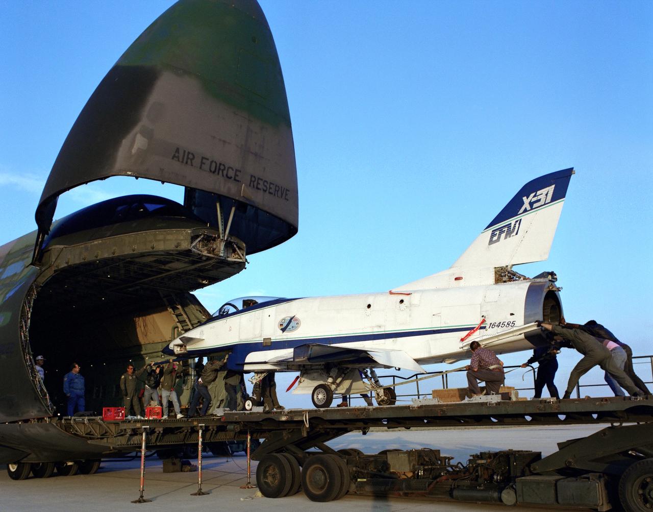
The X-31 Enhanced Fighter Maneuverability Technology Demonstrator Aircraft, based at the NASA Dryden Flight Research Center, Edwards, California, begins rolling aboard an Air Force Reserve C-5 transport which ferried it on May 22, 1995 to Europe where it was flown in the Paris Air Show in June 1995. To fit in the C-5 the right wing of the X-31 had to be removed. At the air show, the X-31 demonstrated the value of using thrust vectoring (directing engine exhaust flow) coupled with advanced flight control systems to provide controlled flight at very high angles of attack.

This photograph depicts an air-breathing rocket engine prototype in the test bay at the General Applied Science Lab facility in Ronkonkoma, New York. Air-breathing engines, known as rocket based, combined-cycle engines, get their initial take-off power from specially designed rockets, called air-augmented rockets, that boost performance about 15 percent over conventional rockets. When the vehicle's velocity reaches twice the speed of sound, the rockets are turned off and the engine relies totally on oxygen in the atmosphere to burn hydrogen fuel, as opposed to a rocket that must carry its own oxygen, thus reducing weight and flight costs. Once the vehicle has accelerated to about 10 times the speed of sound, the engine converts to a conventional rocket-powered system to propel the craft into orbit or sustain it to suborbital flight speed. NASA's Advanced Space Transportation Program at Marshall Space Flight Center, along with several industry partners and collegiate forces, is developing this technology to make space transportation affordable for everyone from business travelers to tourists. The goal is to reduce launch costs from today's price tag of $10,000 per pound to only hundreds of dollars per pound. NASA's series of hypersonic flight demonstrators currently include three air-breathing vehicles: the X-43A, X-43B and X-43C.
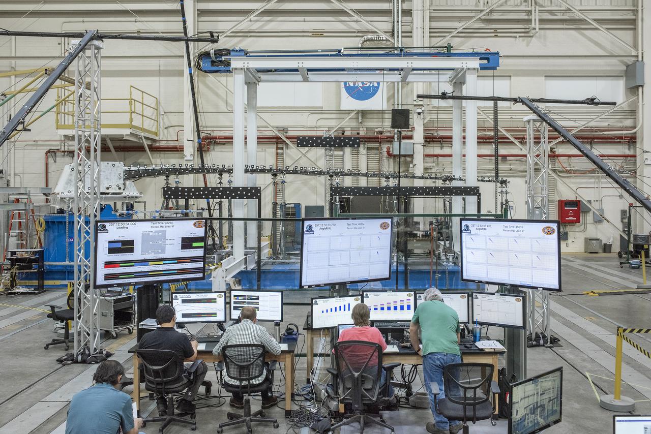
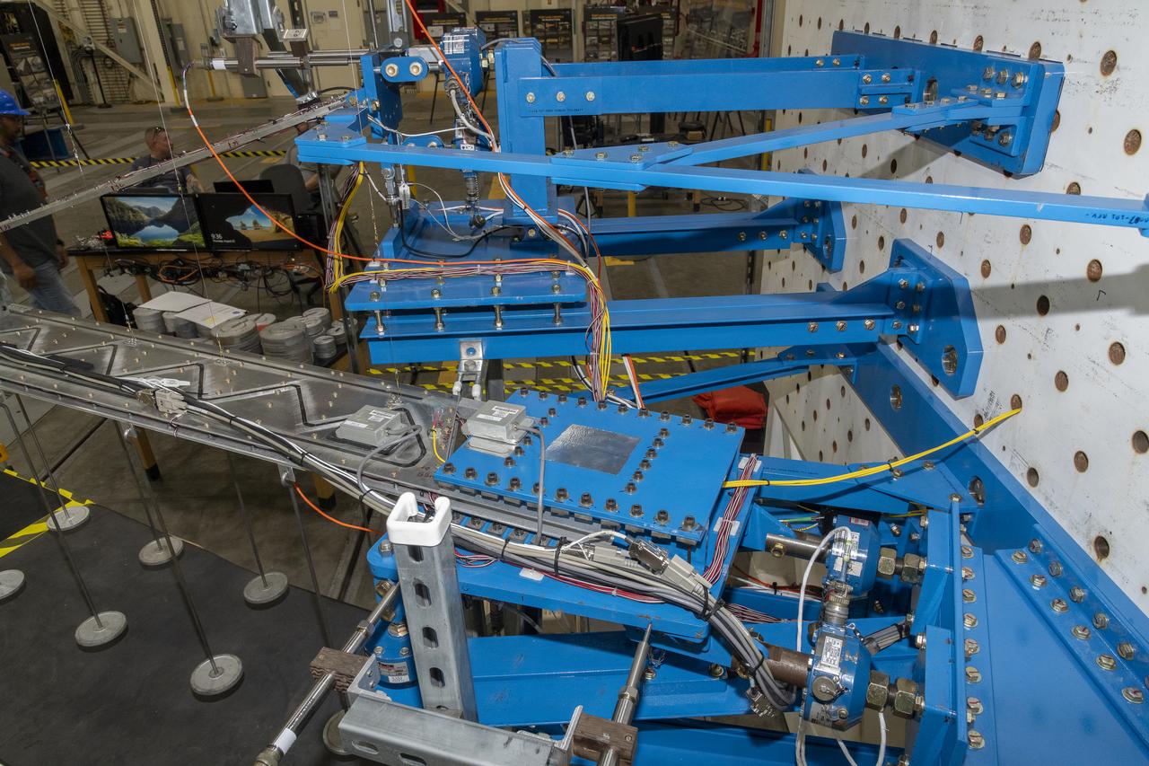
This broad view of the Flight Loads Laboratory at NASA’s Armstrong Flight Research Center in California shows the test set up for the high-aspect ratio Passive Aeroelastic Tailored wing.
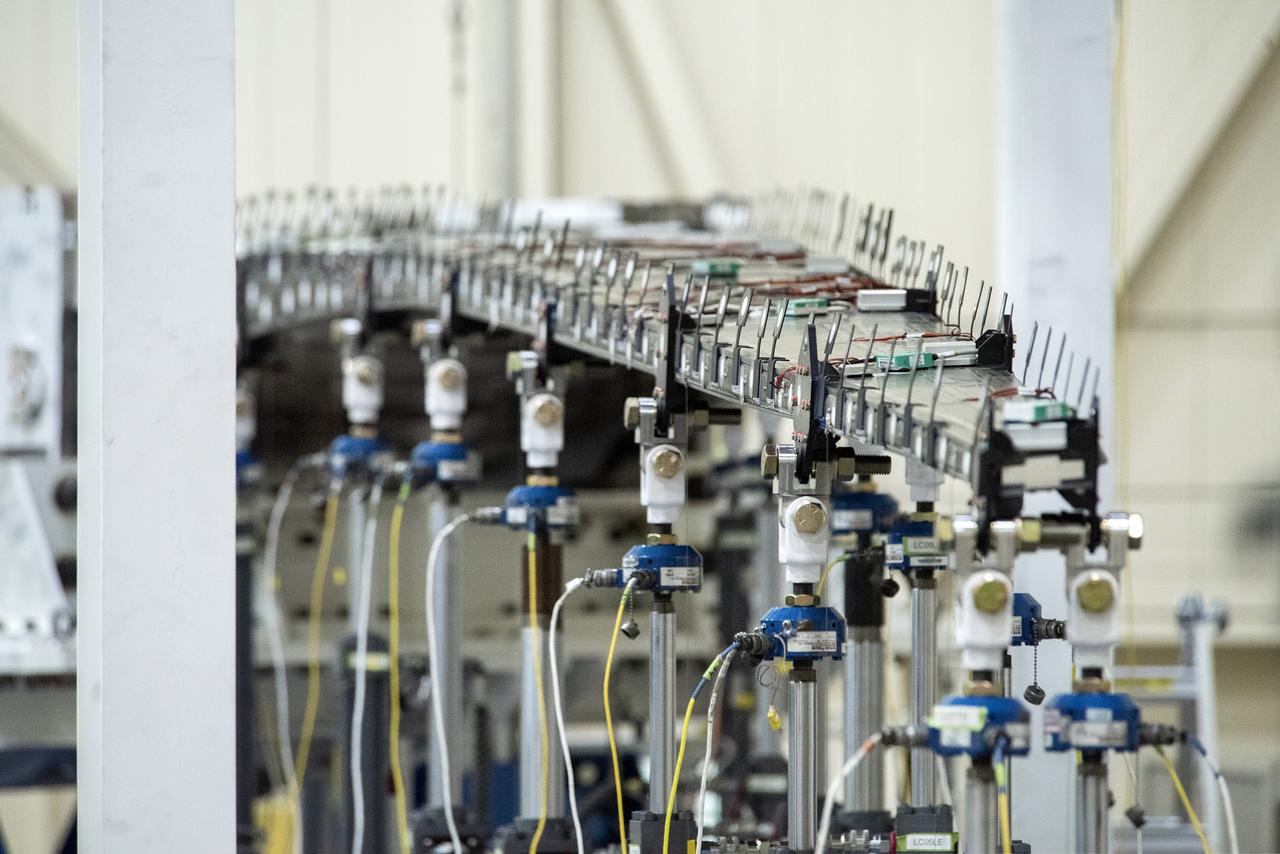
The Passive Aeroelastic Tailored wing is tested in a fixture at the NASA Armstrong Flight Test Center’s Flight Loads Laboratory in California.
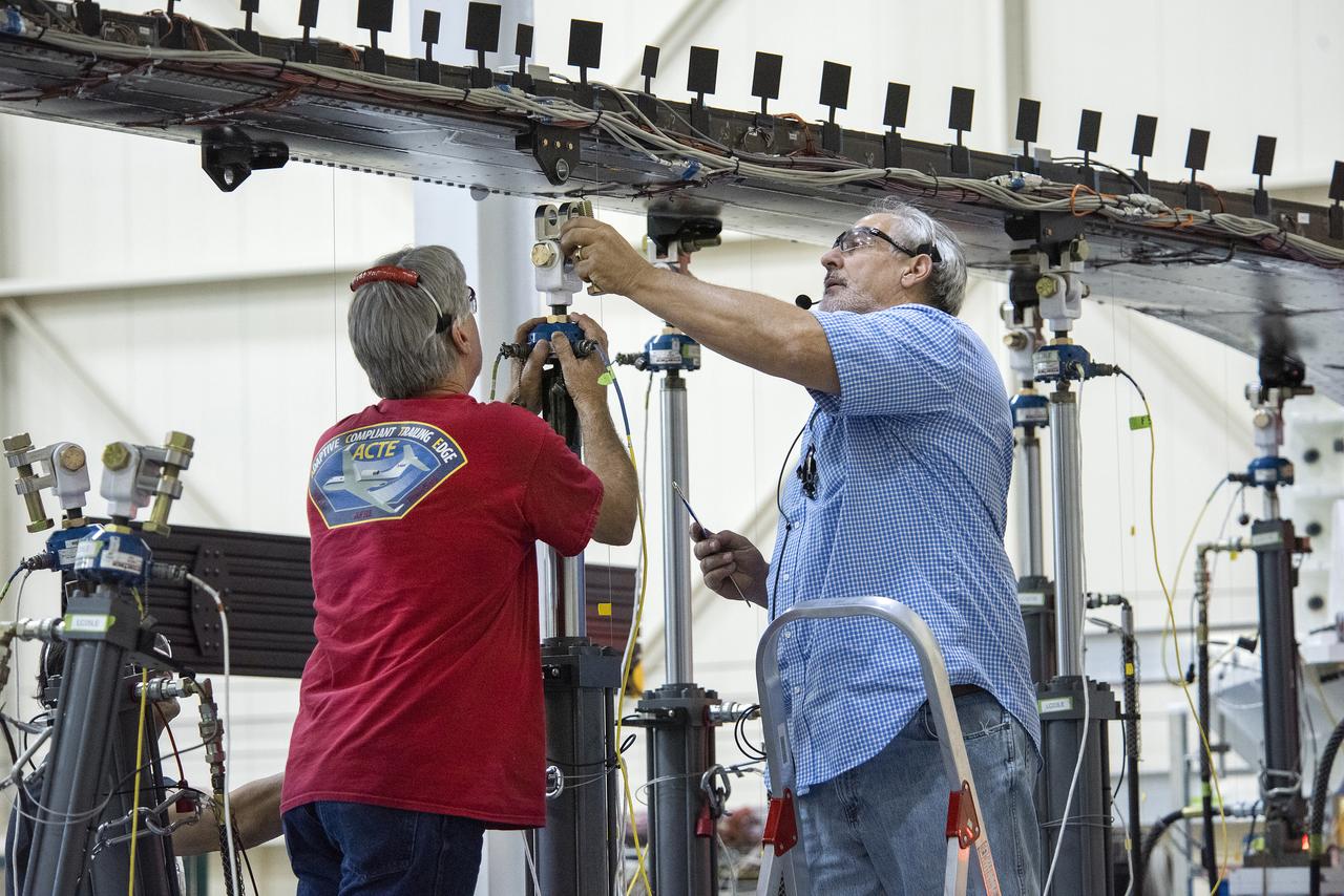
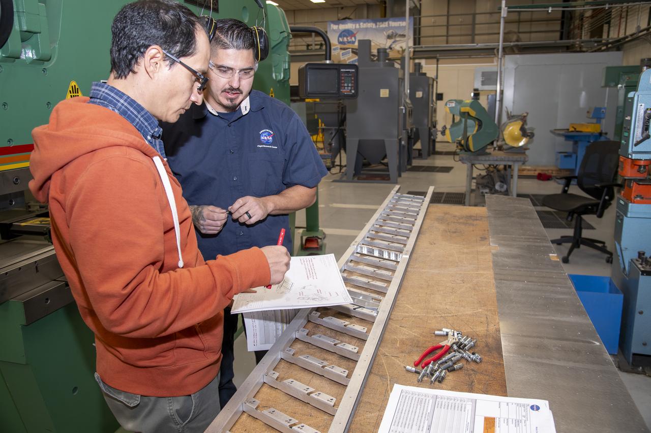
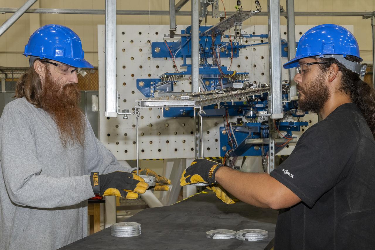
Wally Hargis, left, and Ted Powers complete preparations for testing the Passive Aeroelastic Tailored wing.

Eric Sinks, left, and Ron Haraguchi work through a challenge with the wiring from the Passive Aeroelastic Tailored wing to the test fixture.
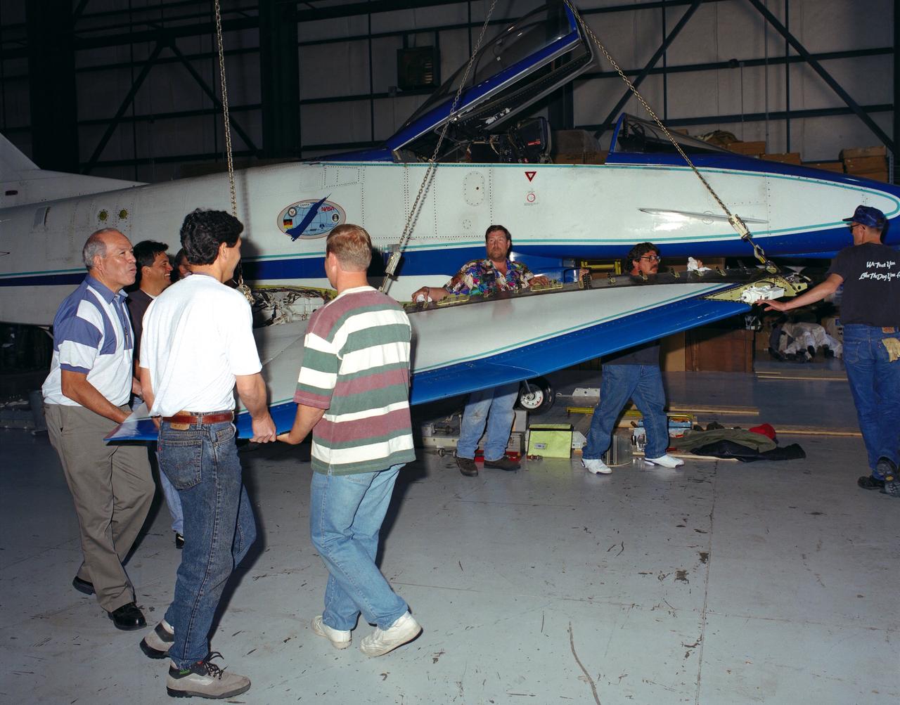
U.S. and German personnel of the X-31 Enhanced Fighter Maneuverability Technology Demonstrator aircraft program removing the right wing of the aircraft, which was ferried from Edwards Air Force Base, California, to Europe on May 22, 1995 aboard an Air Force Reserve C-5 transport. The X-31, based at the NASA Dryden Flight Research Center was ferried to Europe and flown in the Paris Air Show in June. The wing of the X-31 was removed on May 18, 1995, to allow the aircraft to fit inside the C-5 fuselage. Officials of the X-31 project used Manching, Germany, as a staging base to prepare the aircraft for the flight demonstration. At the air show, the X-31 demonstrated the value of using thrust vectoring (directing engine exhaust flow) coupled with advanced flight control systems to provide controlled flight at very high angles of attack. The aircraft arrived back at Edwards in a Air Force Reserve C-5 on June 25, 1995 and off loaded at Dryden June 27. The X-31 aircraft was developed jointly by Rockwell International's North American Aircraft Division (now part of Boeing) and Daimler-Benz Aerospace (formerly Messerschmitt-Bolkow-Blohm), under sponsorship by the U.S. Department of Defense and the German Federal Ministry of Defense.
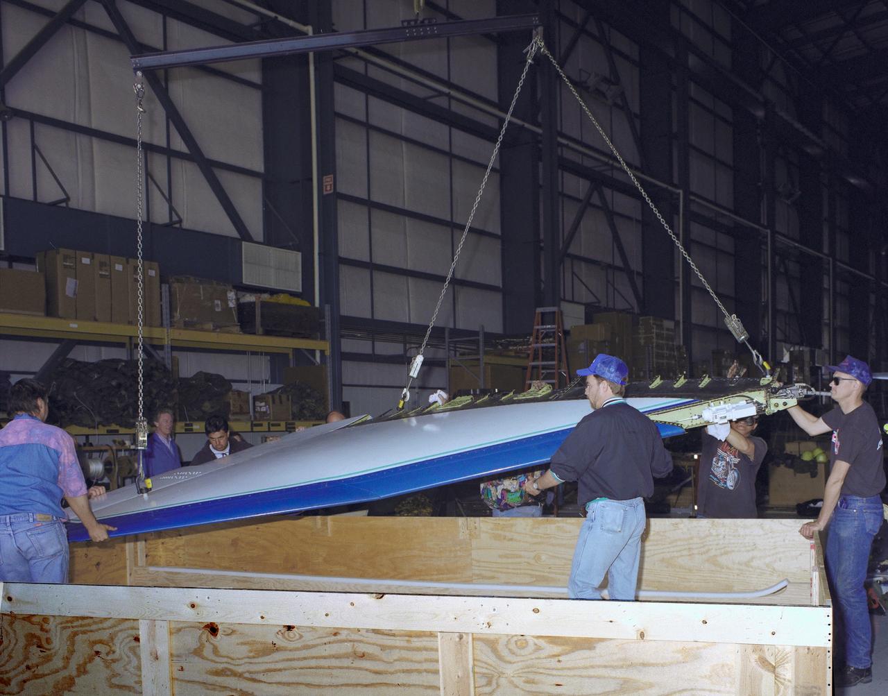
The right wing of the X-31 Enhanced Fighter Maneuverability Technology Demonstrator Aircraft is seen here being put into a shipping container May 18, 1995, at NASA's Dryden Flight Research Center, Edwards, California, by U.S. and German members of the program. To fit inside an Air Force Reserve C-5 transport, which was used to ferry the X-31 to Europe on May 22, 1995, the right wing had to be removed. Manching, Germany, was used as a staging base to prepare the aircraft for participation in the Paris Air Show. At the air show on June 11 through the 18th, the X-31 demonstrated the value of using thrust vectoring (directing engine exhaust flow) coupled with advanced flight control systems to provide controlled flight at very high angles of attack. The aircraft arrived back at Edwards in an Air Force Reserve C-5 on June 25, 1995, and off loaded at Dryden the 27th. The X-31 aircraft was developed jointly by Rockwell International's North American Aircraft Division (now part of Boeing) and Daimler-Benz Aerospace (formerly Messerschmitt-Bolkow-Blohm), under sponsorship by the U.S. Department of Defense and the German Federal Ministry of Defense.
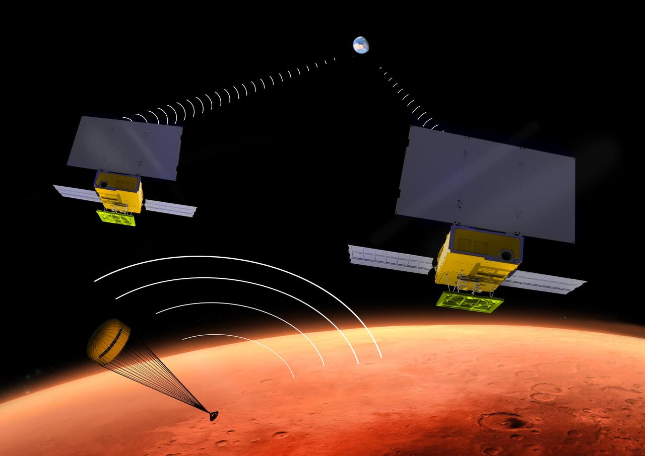
NASA's two MarCO CubeSats will be flying past Mars in September 2016 just as NASA's next Mars lander, InSight, is descending through the Martian atmosphere and landing on the surface. MarCO, for Mars Cube One, will provide an experimental communications relay to inform Earth quickly about the landing. This illustration depicts a moment during the lander's descent when it is transmitting data in the UHF radio band, and the twin MarCO craft are receiving those transmissions while simultaneously relaying the data to Earth in a different radio band. Each of the MarCO twins carries two solar panels for power, and both UHF-band and X-band radio antennas. As a technology demonstration, MarCO could lead to other "bring-your-own-relay" mission designs and also to use of miniature spacecraft for a wide diversity of interplanetary missions. MarCO is the first interplanetary use of CubeSat technologies for small spacecraft. CubeSats are a class of spacecraft based on a standardized small size and modular use of off-the-shelf technologies to streamline development. Many have been made by university students, and dozens have been launched into Earth orbit using extra payload mass available on launches of larger spacecraft. The two briefcase-size MarCO CubeSats will ride along with InSight on an Atlas V launch vehicle lifting off in March 2016 from Vandenberg Air Force Base, California. MarCO is a technology demonstration aspect of the InSight mission and not needed for that mission's success. InSight, an acronym for Interior Exploration using Seismic Investigations, Geodesy and Heat Transport, will investigate the deep interior of Mars to advance understanding of how rocky planets, including Earth, formed and evolved. After launch, the MarCO twins and InSight will be navigated separately to Mars. Note: After thorough examination, NASA managers have decided to suspend the planned March 2016 launch of the Interior Exploration using Seismic Investigations Geodesy and Heat Transport (InSight) mission. The decision follows unsuccessful attempts to repair a leak in a section of the prime instrument in the science payload. http://photojournal.jpl.nasa.gov/catalog/PIA19388
Researchers test a 10-foot Mock Truss-Braced Wing at NASA’s Armstrong Flight Research Center in Edwards, California. The test team makes observations between tests. The aircraft concept involves a wing braced on an aircraft using diagonal struts that also add lift and could result in significantly improved aerodynamics.
Researchers test a 10-foot Mock Truss-Braced Wing at NASA’s Armstrong Flight Research Center in Edwards, California. The aircraft concept involves a wing braced on an aircraft using diagonal struts that also add lift and could result in significantly improved aerodynamics.
Engineering technician Jeff Howell removes tape from the Mock Truss-Braced Wing 10-foot model at NASA’s Armstrong Flight Research Center in Edwards, California. The tape was used to limit the amount of epoxy on the model wing during the process to secure the fiber optic strain sensors to the wing.

Matthew Sanchez attaches the strut and the wing to ensure they fit together as intended for a 10-foot model of the Transonic Truss-Braced Wing at NASA’s Armstrong Flight Research Center, in Edwards, California. The aircraft concept involves a wing braced on an aircraft using diagonal struts that also add lift and could result in significantly improved aerodynamics.
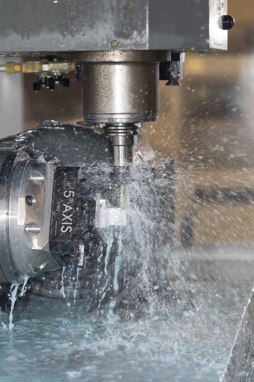
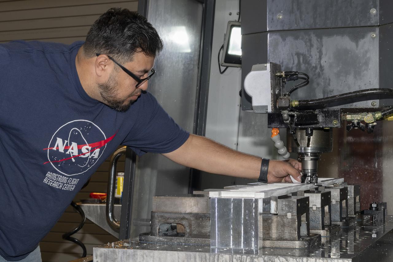
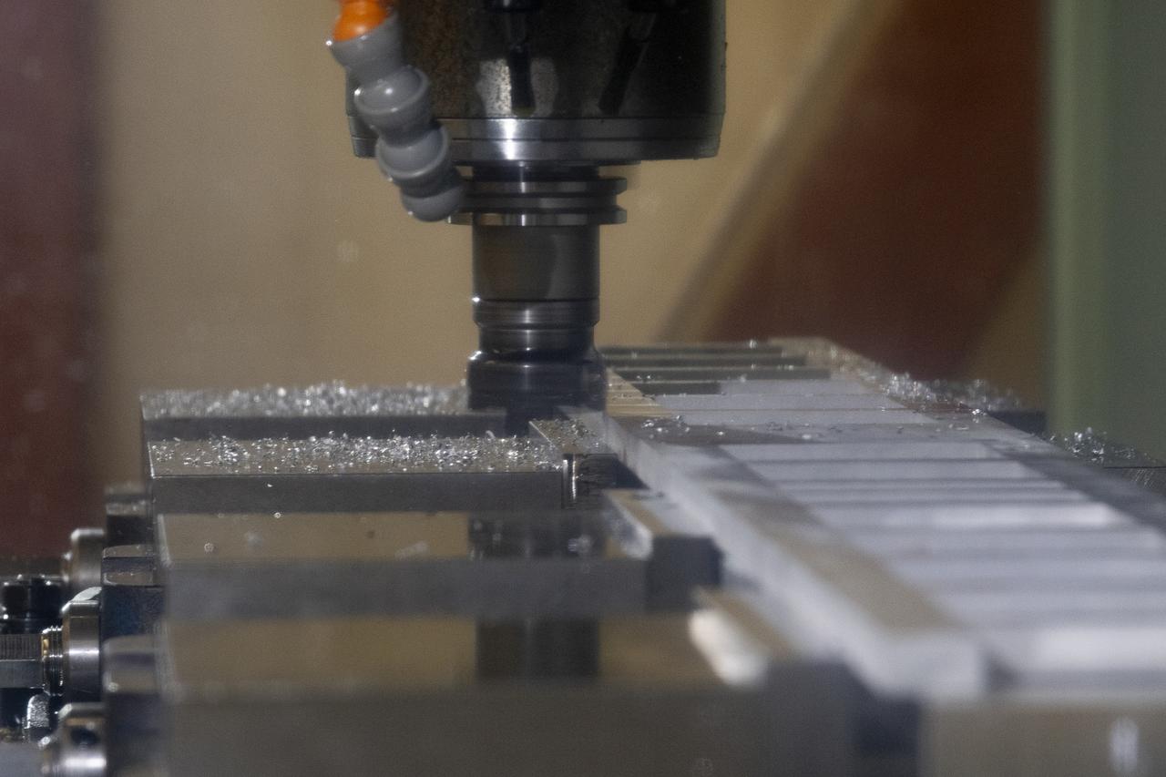
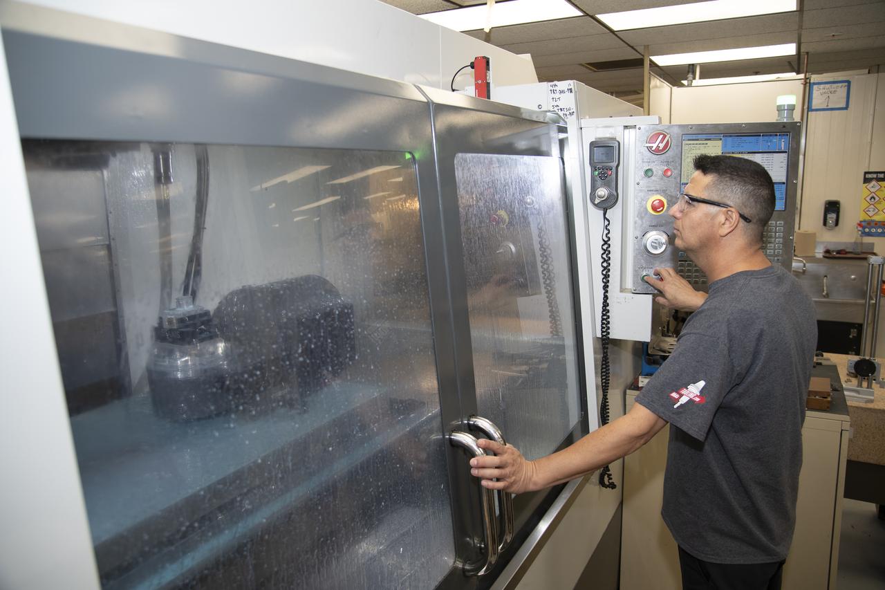
A machine cuts, rotates, and turns a block of aluminum to make a forward wing strut fastener for a 10-foot model of the Transonic Truss-Braced Wing at NASA’s Armstrong Flight Research Center, in Edwards, California. The aircraft concept involves a wing braced on an aircraft using diagonal struts that also add lift and could result in significantly improved aerodynamics.
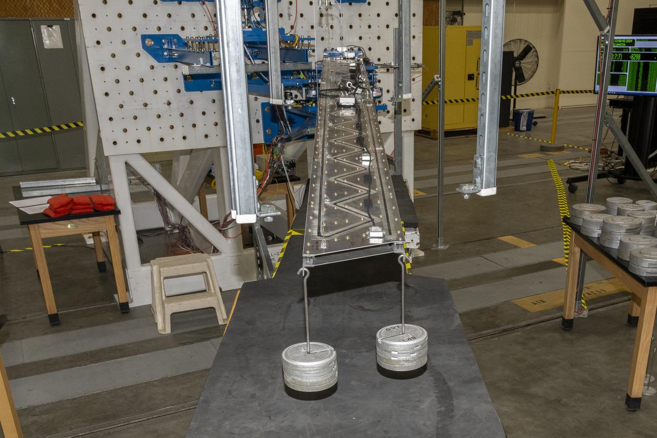
Researchers test a 10-foot Mock Truss-Braced Wing at NASA’s Armstrong Flight Research Center in Edwards, California. A view from above shows the test structure, the wing, and the strut. The aircraft concept involves a wing braced on an aircraft using diagonal struts that also add lift and could result in significantly improved aerodynamics.
Matthew Sanchez consults with Andrew Holguin on the strut for a 10-foot model of the Transonic Truss-Braced Wing at NASA’s Armstrong Flight Research Center, in Edwards, California. The aircraft concept involves a wing braced on an aircraft using diagonal struts that also add lift and could result in significantly improved aerodynamics.
Researchers test a 10-foot Mock Truss-Braced Wing at NASA’s Armstrong Flight Research Center in Edwards, California. From left, ground vibration test director Ben Park, Natalie Spivey, and Samson Truong, prepare for a vibration test. The aircraft concept involves a wing braced on an aircraft using diagonal struts that also add lift and could result in significantly improved aerodynamics.
German Escobar works on milling the strut frame assembly for a 10-foot model of the Transonic Truss-Braced Wing at NASA’s Armstrong Flight Research Center, in Edwards, California. The aircraft concept involves a wing braced on an aircraft using diagonal struts that also add lift and could result in significantly improved aerodynamics.
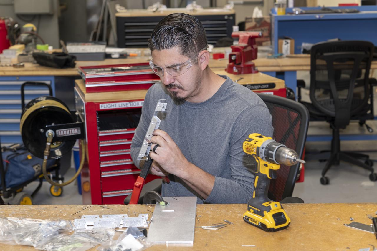
Matthew Sanchez assembles wing ribs for a 10-foot model of the Transonic Truss-Braced Wing at NASA’s Armstrong Flight Research Center, in Edwards, California. The aircraft concept involves a wing braced on an aircraft using diagonal struts that also add lift and could result in significantly improved aerodynamics.
A milling machine drills holes in the strut frame assembly for a 10-foot model of the Transonic Truss-Braced Wing at NASA’s Armstrong Flight Research Center, in Edwards, California. The aircraft concept involves a wing braced on an aircraft using diagonal struts that also add lift and could result in significantly improved aerodynamics.
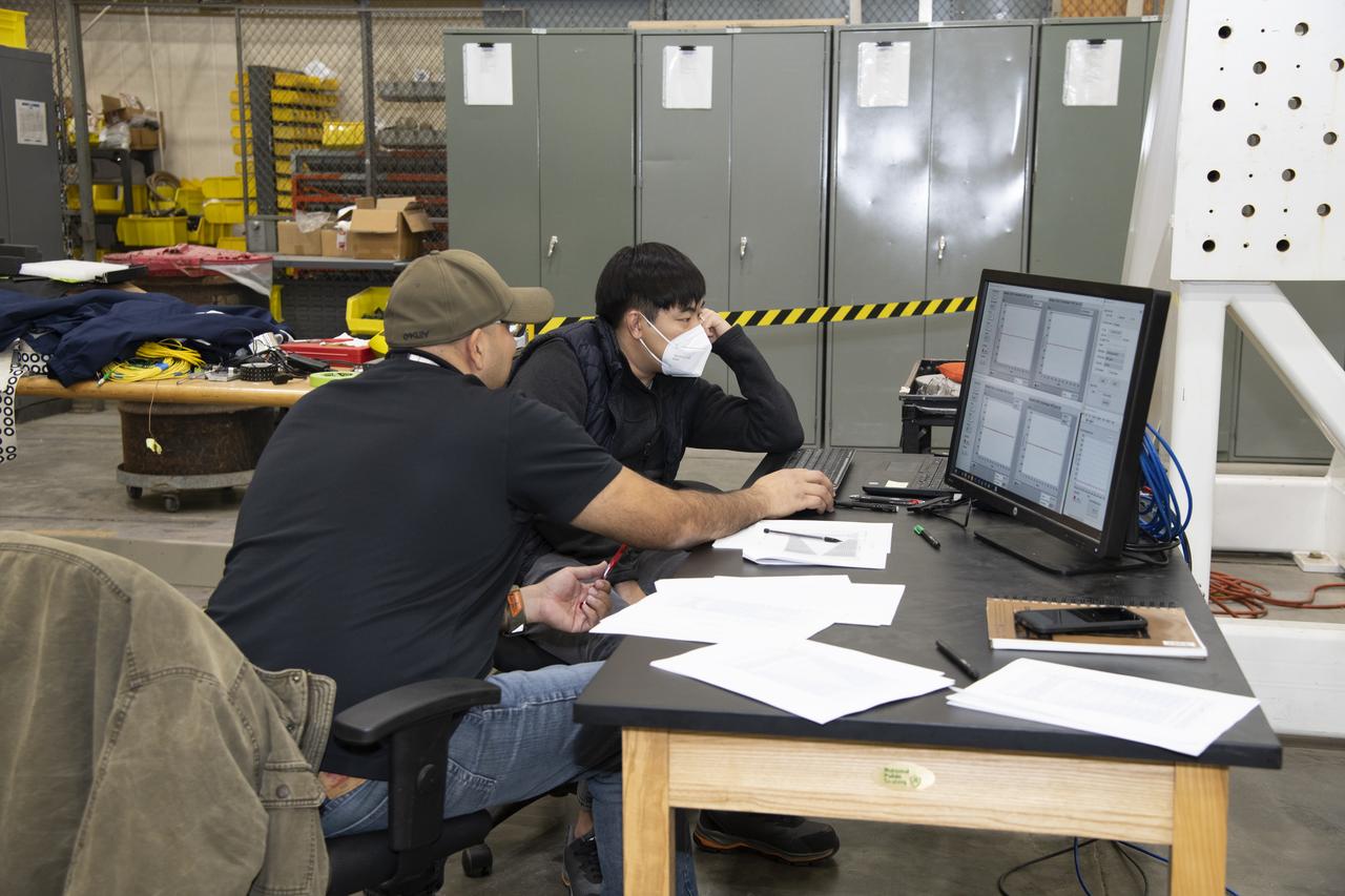
Frank Pena and Benjamin Park watch as data streams in from tests on a 6-foot model of the Transonic Truss-Braced Wing at NASA’s Armstrong Flight Research Center, in Edwards, California.
Researchers test a 10-foot Mock Truss-Braced Wing at NASA’s Armstrong Flight Research Center in Edwards, California. Charlie Eloff, left, and Lucas Oramas add weight to the test wing to apply stress used to determine its limits. The aircraft concept involves a wing braced on an aircraft using diagonal struts that also add lift and could result in significantly improved aerodynamics.
Matthew Sanchez places the strut and the wing side-by-side before assembling them for a check to ensure they fit together as intended for a 10-foot model of the Transonic Truss-Braced Wing at NASA’s Armstrong Flight Research Center, in Edwards, California. The aircraft concept involves a wing braced on an aircraft using diagonal struts that also add lift and could result in significantly improved aerodynamics.
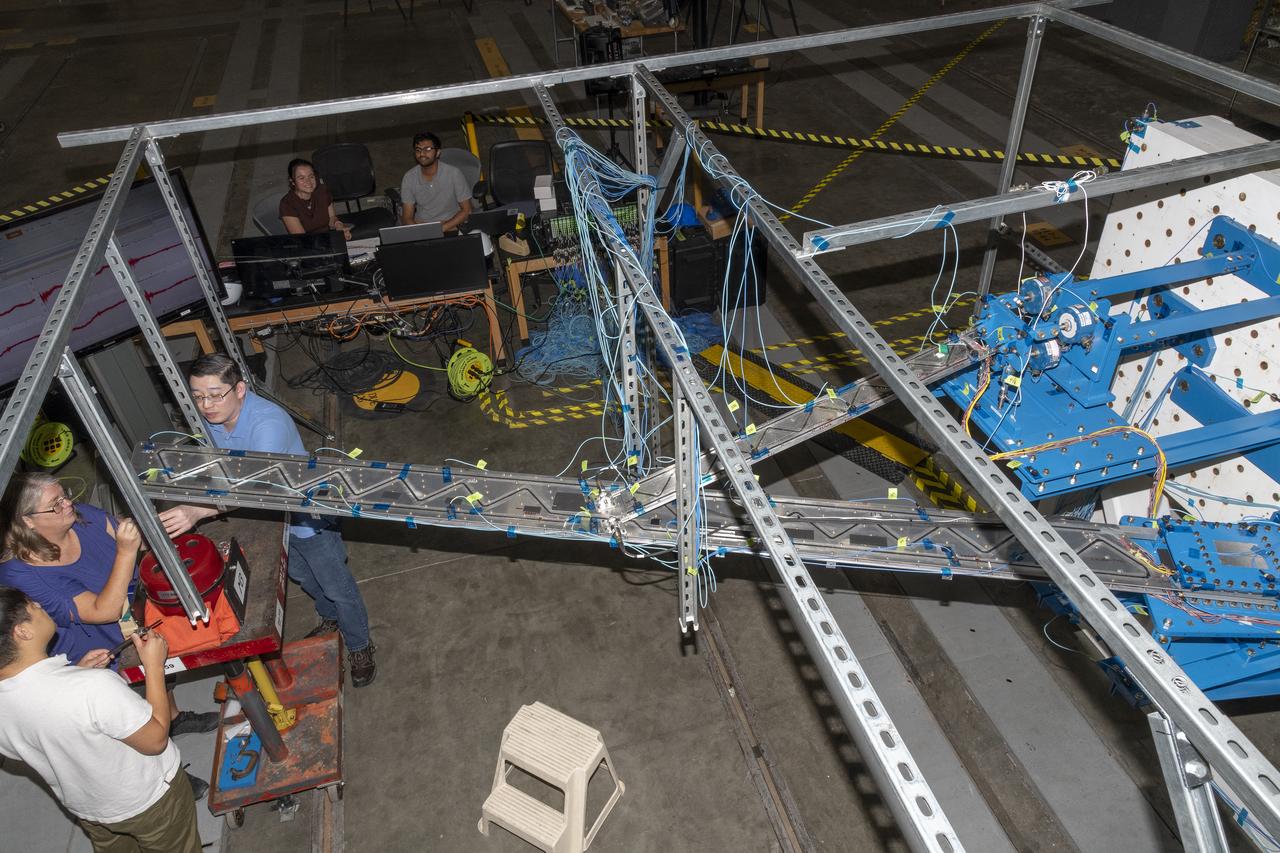
Researchers test a 10-foot Mock Truss-Braced Wing at NASA’s Armstrong Flight Research Center in Edwards, California. The infrastructure, in blue, holds the wing and truss and enables the test. The aircraft concept involves a wing braced on an aircraft using diagonal struts that also add lift and could result in significantly improved aerodynamics.
Instrumentation of the wing and strut that comprise the Mock Truss-Braced Wing 10-foot model are complete at NASA’s Armstrong Flight Research Center in Edwards, California.
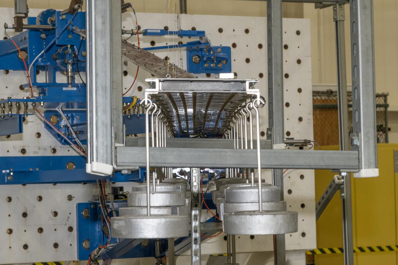
Researchers test a 10-foot Mock Truss-Braced Wing at NASA’s Armstrong Flight Research Center in Edwards, California. Weights are hung from the wing to apply stress used to determine its limits. The aircraft concept involves a wing braced on an aircraft using diagonal struts that also add lift and could result in significantly improved aerodynamics.

Jose Vasquez programed a machine to cut, rotate and turn a block of steel to form a jury strut adaptor for a 10-foot model of the Transonic Truss-Braced Wing at NASA’s Armstrong Flight Research Center, in Edwards, California. The aircraft concept involves a wing braced on an aircraft using diagonal struts that also add lift and could result in significantly improved aerodynamics.
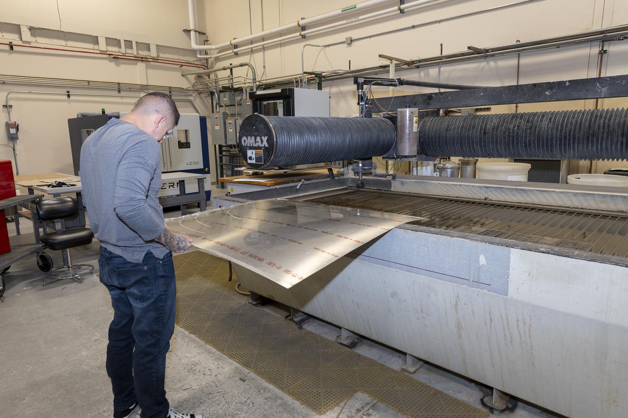
Matthew Sanchez prepares a sheet of aluminum that will be cut into the outer layer of the strut for the 10-foot model of the Transonic Truss-Braced Wing at NASA’s Armstrong Flight Research Center, in Edwards, California. The aircraft concept involves a wing braced on an aircraft using diagonal struts that also add lift and could result in significantly improved aerodynamics.
Researchers test a 10-foot Mock Truss-Braced Wing at NASA’s Armstrong Flight Research Center in Edwards, California. Weights are added to the wingtip to apply stress used to determine its limits. The aircraft concept involves a wing braced on an aircraft using diagonal struts that also add lift and could result in significantly improved aerodynamics.
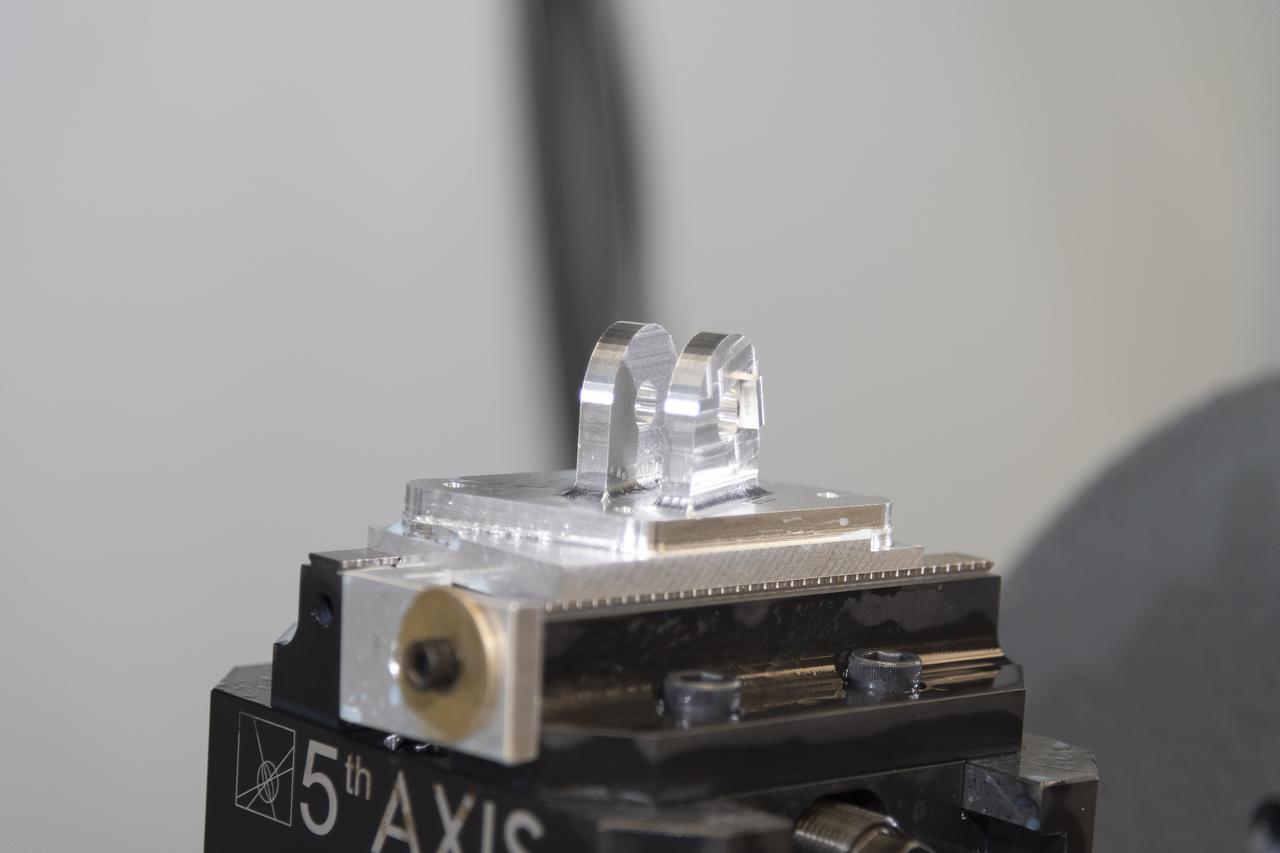
A block of aluminum is transformed by a machine programmed to cut, rotate, and turn it to make a forward wing strut fastener for a 10-foot model of the Transonic Truss-Braced Wing at NASA’s Armstrong Flight Research Center, in Edwards, California. The aircraft concept involves a wing braced on an aircraft using diagonal struts that also add lift and could result in significantly improved aerodynamics.
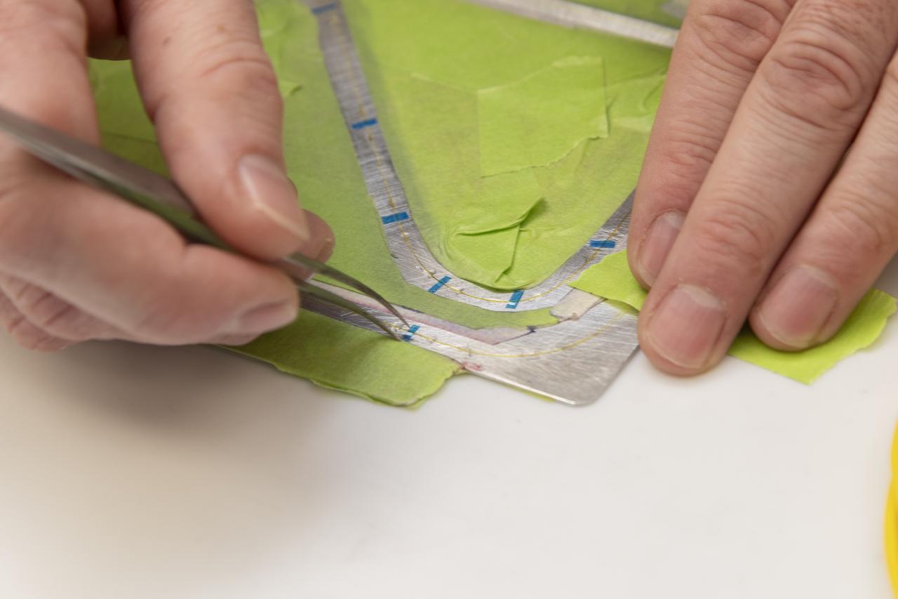
Engineering technician Jeff Howell removes thin pieces of tape from fiber used for a bonding process on the Mock Truss-Braced Wing 10-foot model at NASA’s Armstrong Flight Research Center in Edwards, California.
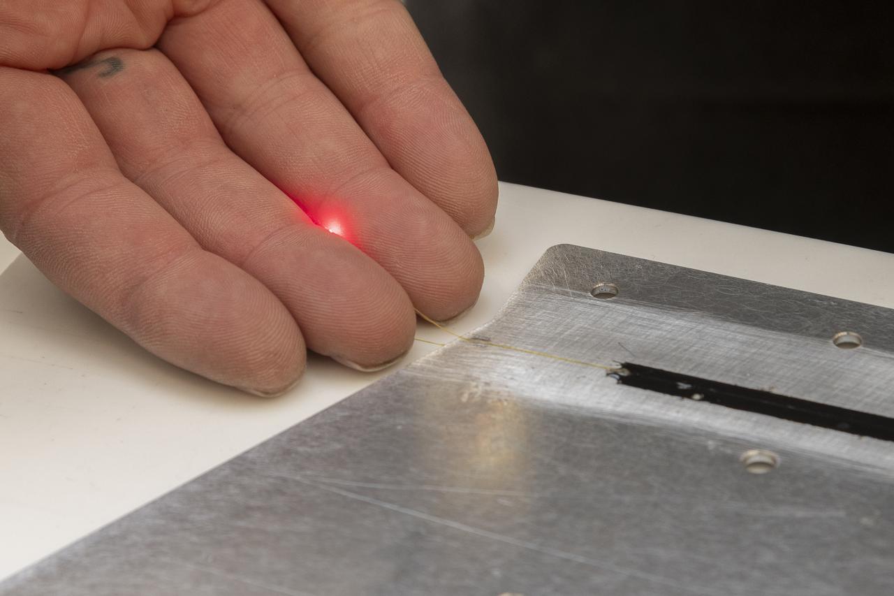
A red light confirms that the fiber of the Fiber Optic Sensing System installed on the Mock Truss-Braced Wing 10-foot model works as intended at NASA’s Armstrong Flight Research Center in Edwards, California. The fiber, which is about the thickness of a human hair, is part of a system that can provide strain information researchers can use to determine the model’s durability.
Researchers test a 10-foot Mock Truss-Braced Wing at NASA’s Armstrong Flight Research Center in Edwards, California. Frank Pena, test director, checks the mock wing. The aircraft concept involves a wing braced on an aircraft using diagonal struts that also add lift and could result in significantly improved aerodynamics.
Matthew Sanchez assembles wing ribs to the 10-foot model of the Transonic Truss-Braced Wing at NASA’s Armstrong Flight Research Center, in Edwards, California. The aircraft concept involves a wing braced on an aircraft using diagonal struts that also add lift and could result in significantly improved aerodynamics.
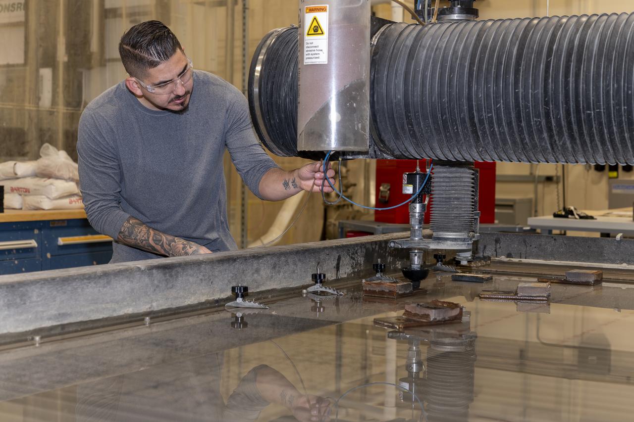
Matthew Sanchez uses a water jet to cut aluminum for the outer layer of the strut for the 10-foot model of the Transonic Truss-Braced Wing at NASA’s Armstrong Flight Research Center, in Edwards, California. The aircraft concept involves a wing braced on an aircraft using diagonal struts that also add lift and could result in significantly improved aerodynamics.

Researchers test a 10-foot Mock Truss-Braced Wing at NASA’s Armstrong Flight Research Center in Edwards, California. From left, test director Frank Pena and Ray Sadler watch as Lucas Oramas, left, and Charlie Eloff add weight to the test wing to apply stress used to determine its limits. The aircraft concept involves a wing braced on an aircraft using diagonal struts that also add lift and could result in significantly improved aerodynamics.
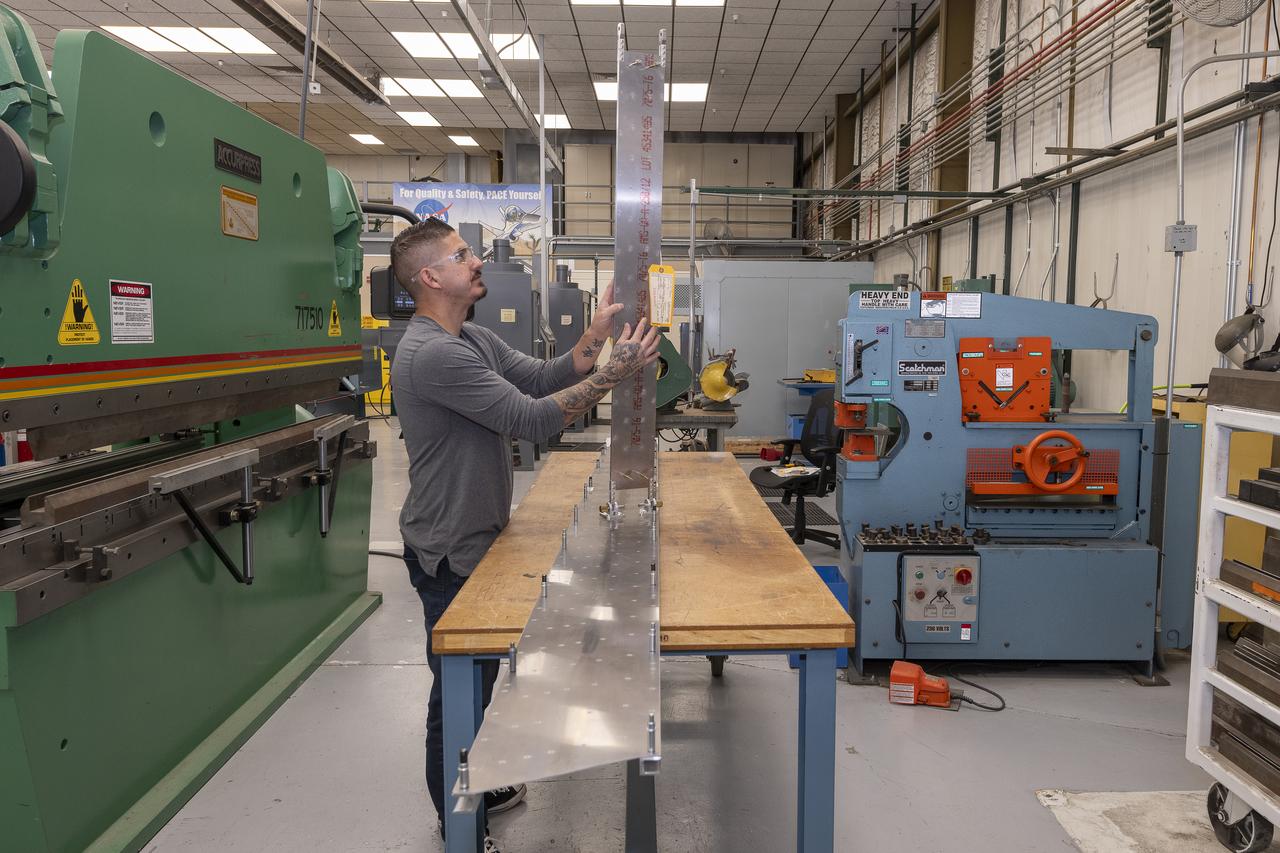
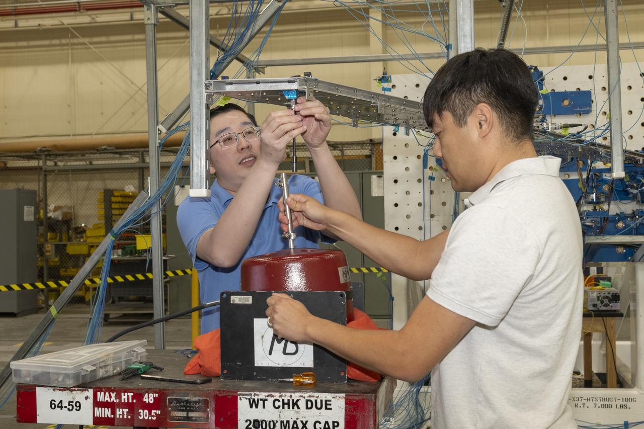
Matthew Sanchez attaches the strut and the wing to ensure they fit together as intended for a 10-foot model of the Transonic Truss-Braced Wing at NASA’s Armstrong Flight Research Center, in Edwards, California. The aircraft concept involves a wing braced on an aircraft using diagonal struts that also add lift and could result in significantly improved aerodynamics.
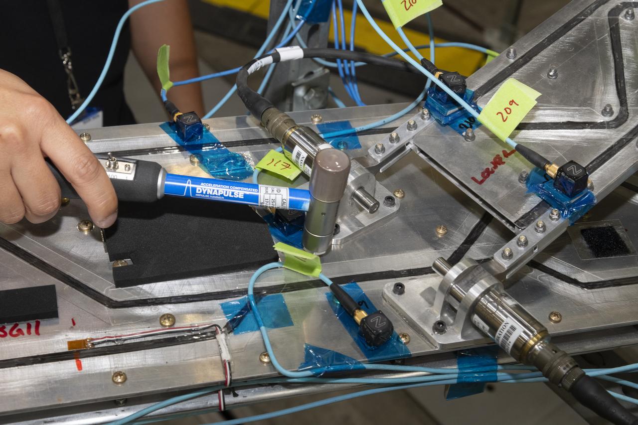
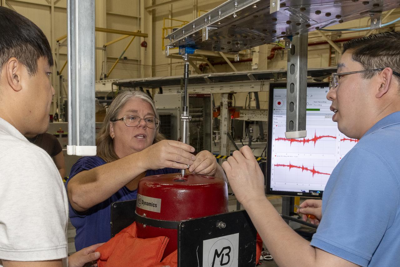
Researchers test a 10-foot Mock Truss-Braced Wing at NASA’s Armstrong Flight Research Center in Edwards, California. Ben Park, NASA mock wing ground vibration test director, taps the wing structure with an instrumented hammer in key locations and sensors monitor the results. The aircraft concept involves a wing braced on an aircraft using diagonal struts that also add lift and could result in significantly improved aerodynamics.

Engineering technician Jeff Howell mounts conventional strain gauges to the Mock Truss-Braced Wing 10-foot model at NASA’s Armstrong Flight Research Center in Edwards, California. The conventional system data will be compared the Fiber Optic Sensing System developed at the center on the same wing to see how well the testing methods match.

Researchers test a 10-foot Mock Truss-Braced Wing at NASA’s Armstrong Flight Research Center in Edwards, California. Jonathan Lopez, from left, and Jeff Howell watch test data as it is collected. The aircraft concept involves a wing braced on an aircraft using diagonal struts that also add lift and could result in significantly improved aerodynamics.
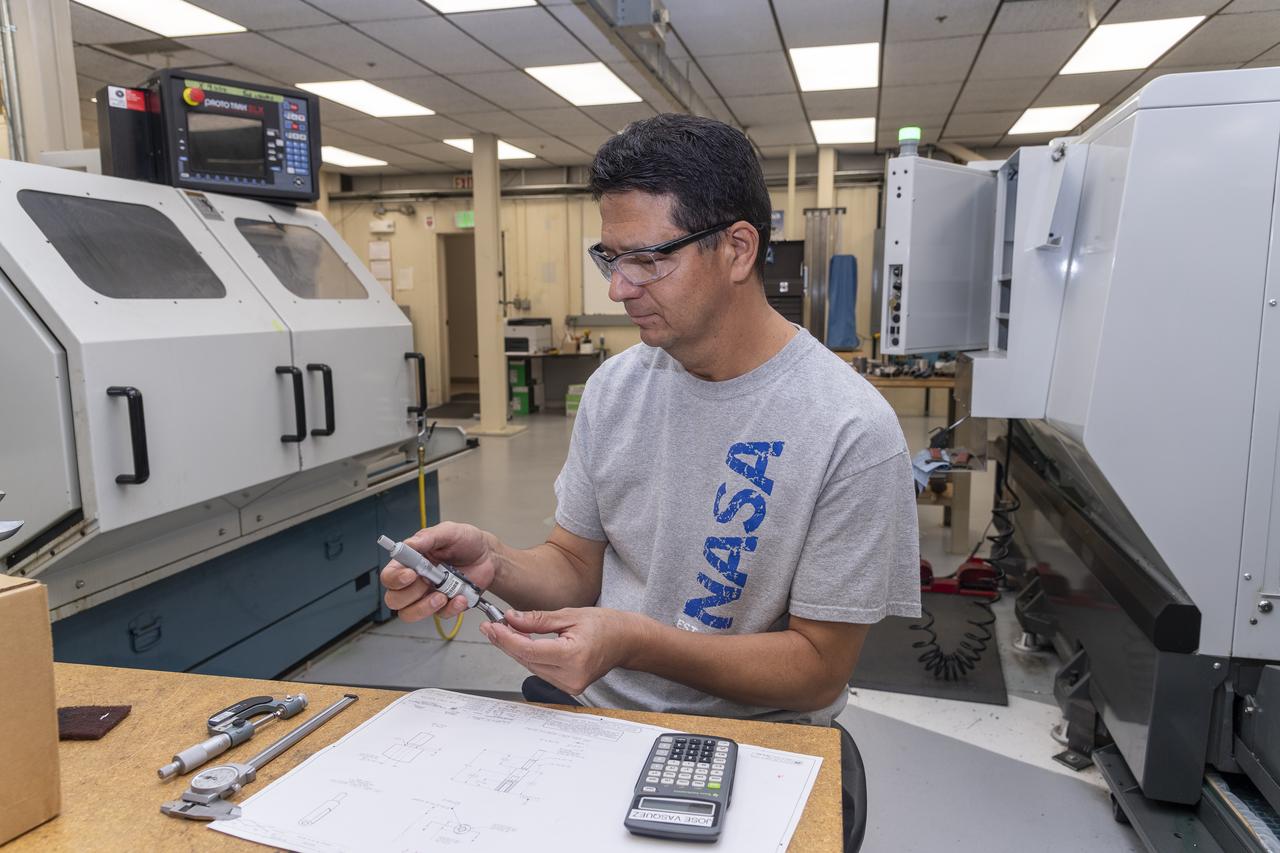
Jose Vasquez verifies a jury strut adaptor created for a 10-foot model of the Transonic Truss-Braced Wing at NASA’s Armstrong Flight Research Center, in Edwards, California. The aircraft concept involves a wing braced on an aircraft using diagonal struts that also add lift and could result in significantly improved aerodynamics.

Aaron Rumsey and Beto Hinojos carefully add weight to a 6-foot model of the Transonic Truss-Braced Wing at NASA’s Armstrong Flight Research Center, in Edwards, California. The aircraft concept involves a wing braced on an aircraft using diagonal struts that also add lift and could result in significantly improved aerodynamics.
Jose Vasquez uses a machine to cut, rotate and turn a block of aluminum to make a forward wing strut fastener for a 10-foot model of the Transonic Truss-Braced Wing at NASA’s Armstrong Flight Research Center, in Edwards, California. The aircraft concept involves a wing braced on an aircraft using diagonal struts that also add lift and could result in significantly improved aerodynamics.

A jury strut adaptor is created for a 10-foot model of the Transonic Truss-Braced Wing at NASA’s Armstrong Flight Research Center, in Edwards, California. The aircraft concept involves a wing braced on an aircraft using diagonal struts that also add lift and could result in significantly improved aerodynamics.
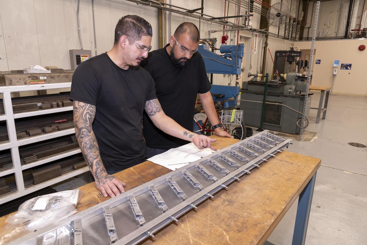
Matthew Sanchez, left, consults with Sal Navarro on assembling wing ribs to the 10-foot model of the Transonic Truss-Braced Wing at NASA’s Armstrong Flight Research Center, in Edwards, California. The aircraft concept involves a wing braced on an aircraft using diagonal struts that also add lift and could result in significantly improved aerodynamics.
Researchers test a 10-foot Mock Truss-Braced Wing at NASA’s Armstrong Flight Research Center in Edwards, California. Samson Truong, from left, and Ben Park, NASA mock wing ground vibration test director, prepare for a vibration test. The aircraft concept involves a wing braced on an aircraft using diagonal struts that also add lift and could result in significantly improved aerodynamics.
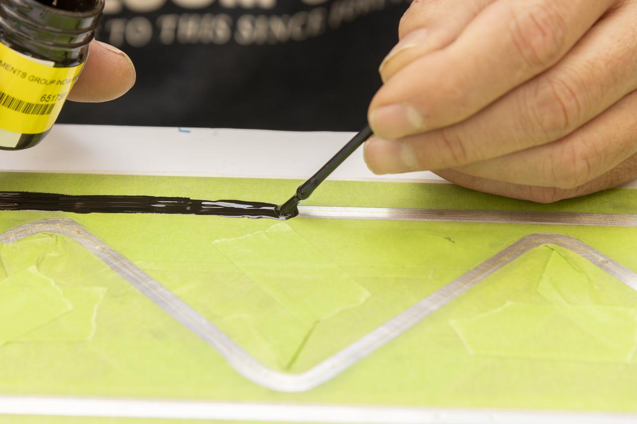
An epoxy is applied to adhere the fiber optic sensor installation on the Mock Truss-Braced Wing 10-foot model at NASA’s Armstrong Flight Research Center in Edwards, California.
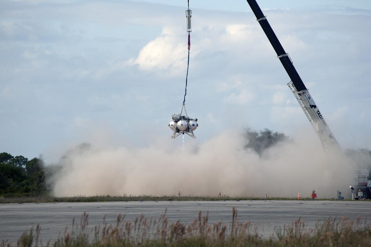
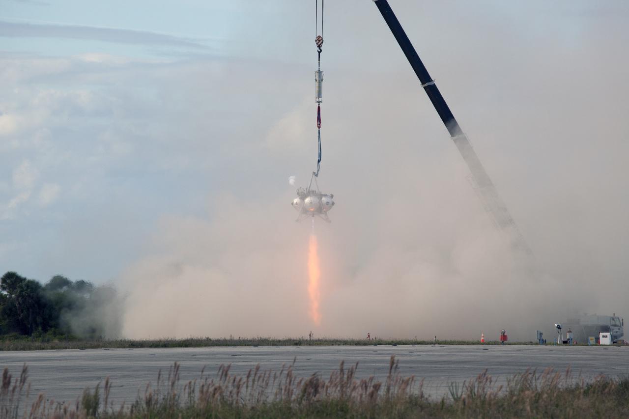
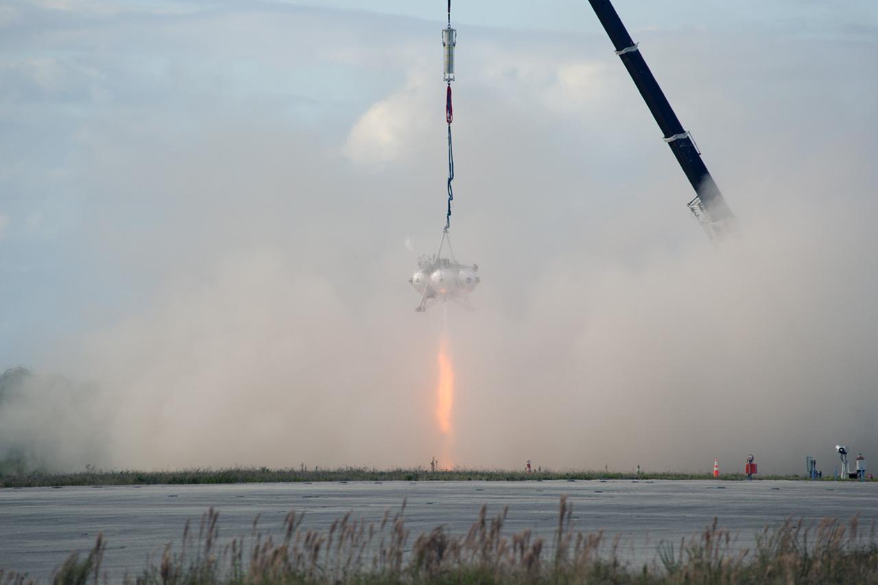
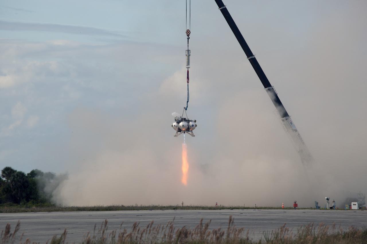
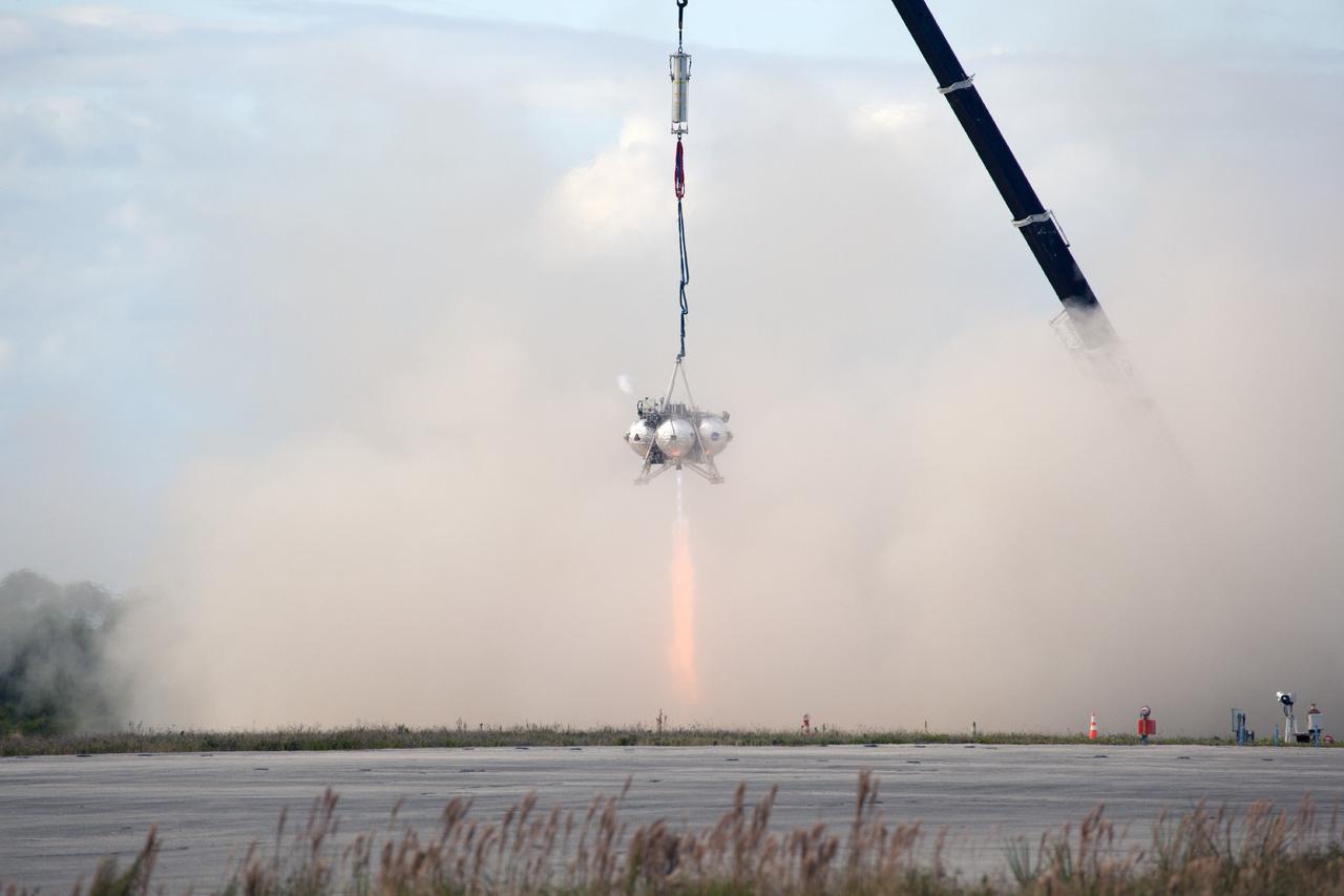
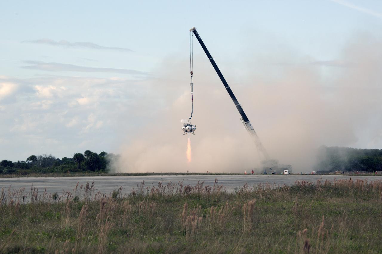
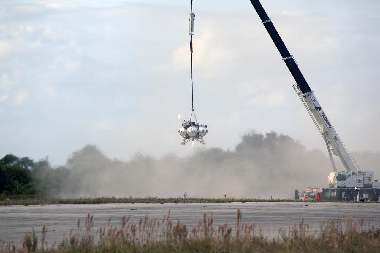
CAPE CANAVERAL, Fla. – At NASA’s Kennedy Space Center in Florida, smoke fills the air as the Project Morpheus prototype lander’s engine fires during a tether test at the north end of the Shuttle Landing Facility. During the test, the lander is lifted 20 feet by crane, and will ascend another 10 feet, maneuver backwards 10 feet, and then fly forward and descend to its original position, landing at the end of the tether onto a transportable launch platform. Testing of the prototype lander was performed at NASA’s Johnson Space Center in Houston in preparation for tethered and free flight testing at Kennedy. The landing facility will provide the lander with the kind of field necessary for realistic testing, complete with rocks, craters and hazards to avoid. Morpheus utilizes an autonomous landing and hazard avoidance technology, or ALHAT, payload that will allow it to navigate to clear landing sites amidst rocks, craters and other hazards during its descent. Project Morpheus is being managed under the Advanced Exploration Systems, or AES, Division in NASA’s Human Exploration and Operations Mission Directorate. The efforts in AES pioneer new approaches for rapidly developing prototype systems, demonstrating key capabilities and validating operational concepts for future human missions beyond Earth orbit. For more information on Project Morpheus, visit http://morpheuslander.jsc.nasa.gov. Photo credit: NASA/Daniel Casper
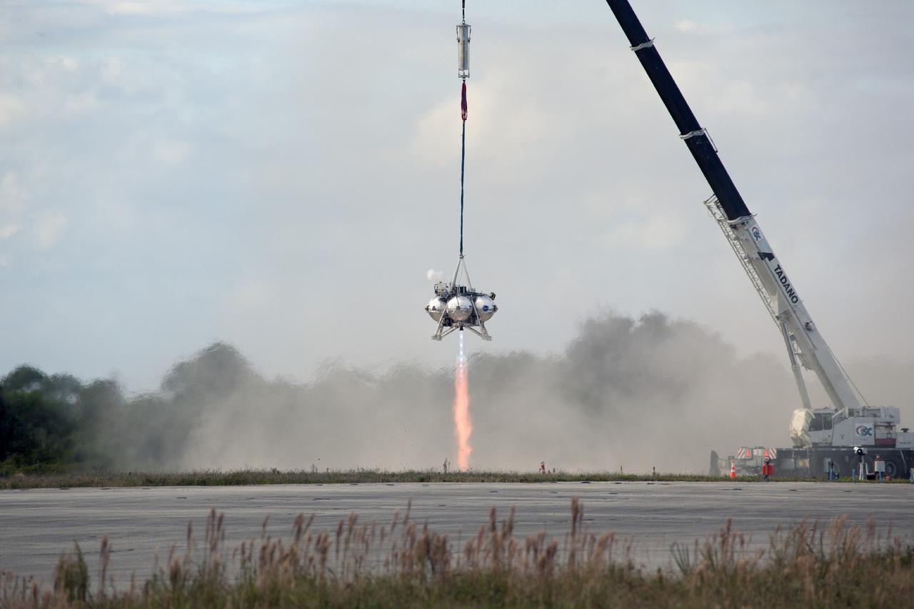
CAPE CANAVERAL, Fla. – At NASA’s Kennedy Space Center in Florida, smoke fills the air as the Project Morpheus prototype lander’s engine fires during a tether test at the north end of the Shuttle Landing Facility. During the test, the lander was lifted 20 feet by crane, and then ascended another 10 feet, maneuvered backwards 10 feet, and then flew forward. It will descend to its original position, landing at the end of the tether onto a transportable launch platform. Testing of the prototype lander was performed at NASA’s Johnson Space Center in Houston in preparation for tethered and free flight testing at Kennedy. The landing facility will provide the lander with the kind of field necessary for realistic testing, complete with rocks, craters and hazards to avoid. Morpheus utilizes an autonomous landing and hazard avoidance technology, or ALHAT, payload that will allow it to navigate to clear landing sites amidst rocks, craters and other hazards during its descent. Project Morpheus is being managed under the Advanced Exploration Systems, or AES, Division in NASA’s Human Exploration and Operations Mission Directorate. The efforts in AES pioneer new approaches for rapidly developing prototype systems, demonstrating key capabilities and validating operational concepts for future human missions beyond Earth orbit. For more information on Project Morpheus, visit http://morpheuslander.jsc.nasa.gov. Photo credit: NASA/Daniel Casper
CAPE CANAVERAL, Fla. – At NASA’s Kennedy Space Center in Florida, smoke fills the air as the Project Morpheus prototype lander’s engine fires during a tether test at the north end of the Shuttle Landing Facility. During the test, the lander was lifted 20 feet by crane, and then ascended another 10 feet, maneuvered backwards 10 feet, and then flew forward. It will descend to its original position, landing at the end of the tether onto a transportable launch platform. Testing of the prototype lander was performed at NASA’s Johnson Space Center in Houston in preparation for tethered and free flight testing at Kennedy. The landing facility will provide the lander with the kind of field necessary for realistic testing, complete with rocks, craters and hazards to avoid. Morpheus utilizes an autonomous landing and hazard avoidance technology, or ALHAT, payload that will allow it to navigate to clear landing sites amidst rocks, craters and other hazards during its descent. Project Morpheus is being managed under the Advanced Exploration Systems, or AES, Division in NASA’s Human Exploration and Operations Mission Directorate. The efforts in AES pioneer new approaches for rapidly developing prototype systems, demonstrating key capabilities and validating operational concepts for future human missions beyond Earth orbit. For more information on Project Morpheus, visit http://morpheuslander.jsc.nasa.gov. Photo credit: NASA/Daniel Casper
CAPE CANAVERAL, Fla. – At NASA’s Kennedy Space Center in Florida, smoke fills the air as the Project Morpheus prototype lander’s engine fires during a tether test at the north end of the Shuttle Landing Facility. During the test, the lander was lifted 20 feet by crane, and then ascended another 10 feet. The lander will maneuver backwards 10 feet, and then fly forward and descend to its original position, landing at the end of the tether onto a transportable launch platform. Testing of the prototype lander was performed at NASA’s Johnson Space Center in Houston in preparation for tethered and free flight testing at Kennedy. The landing facility will provide the lander with the kind of field necessary for realistic testing, complete with rocks, craters and hazards to avoid. Morpheus utilizes an autonomous landing and hazard avoidance technology, or ALHAT, payload that will allow it to navigate to clear landing sites amidst rocks, craters and other hazards during its descent. Project Morpheus is being managed under the Advanced Exploration Systems, or AES, Division in NASA’s Human Exploration and Operations Mission Directorate. The efforts in AES pioneer new approaches for rapidly developing prototype systems, demonstrating key capabilities and validating operational concepts for future human missions beyond Earth orbit. For more information on Project Morpheus, visit http://morpheuslander.jsc.nasa.gov. Photo credit: NASA/Daniel Casper
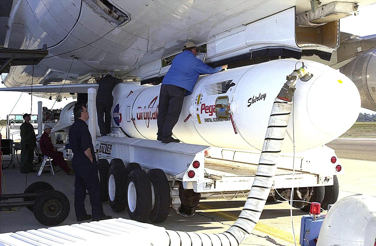
KENNEDY SPACE CENTER, FLA. - At Vandenberg Air Force Base in California, a worker stands on the transporter to attach the Orbital Sciences Pegasus XL launch vehicle and Demonstration of Autonomous Rendezvous Technology (DART) spacecraft to the underbelly of the Orbital Sciences L-1011 aircraft for launch Nov. 9. DART was designed and built for NASA by Orbital Sciences as an advanced flight demonstrator to locate and maneuver near an orbiting satellite. The DART spacecraft weighs about 800 pounds and is nearly 6 feet long and 3 feet in diameter. The Pegasus XL vehicle will launch DART into a circular polar orbit of approximately 475 miles. Once in orbit, DART will make contact with a target satellite, the Multiple Paths, Beyond-Line-of-Sight Communications (MUBLCOM), also built by Orbital Sciences and launched in 1999. DART will then perform several close-proximity operations, such as moving toward and away from the satellite using navigation data provided by on-board sensors. The entire mission will last only 24 hours and will be accomplished without human intervention. The DART flight computer will determine its own path to accomplish its mission objectives.
CAPE CANAVERAL, Fla. – At NASA’s Kennedy Space Center in Florida, smoke fills the air as the Project Morpheus prototype lander’s engine fires during a tether test at the north end of the Shuttle Landing Facility. During the test, the lander was lifted 20 feet by crane, and then ascended another 10 feet, maneuvered backwards 10 feet, and then flew forward. It will descend to its original position, landing at the end of the tether onto a transportable launch platform. Testing of the prototype lander was performed at NASA’s Johnson Space Center in Houston in preparation for tethered and free flight testing at Kennedy. The landing facility will provide the lander with the kind of field necessary for realistic testing, complete with rocks, craters and hazards to avoid. Morpheus utilizes an autonomous landing and hazard avoidance technology, or ALHAT, payload that will allow it to navigate to clear landing sites amidst rocks, craters and other hazards during its descent. Project Morpheus is being managed under the Advanced Exploration Systems, or AES, Division in NASA’s Human Exploration and Operations Mission Directorate. The efforts in AES pioneer new approaches for rapidly developing prototype systems, demonstrating key capabilities and validating operational concepts for future human missions beyond Earth orbit. For more information on Project Morpheus, visit http://morpheuslander.jsc.nasa.gov. Photo credit: NASA/Daniel Casper
CAPE CANAVERAL, Fla. – At NASA’s Kennedy Space Center in Florida, smoke fills the air as the Project Morpheus prototype lander’s engine fires during a tether test at the north end of the Shuttle Landing Facility. During the test, the lander was lifted 20 feet by crane, and then ascended another 10 feet, maneuvered backwards 10 feet, and then flew forward. It will descend to its original position, landing at the end of the tether onto a transportable launch platform. Testing of the prototype lander was performed at NASA’s Johnson Space Center in Houston in preparation for tethered and free flight testing at Kennedy. The landing facility will provide the lander with the kind of field necessary for realistic testing, complete with rocks, craters and hazards to avoid. Morpheus utilizes an autonomous landing and hazard avoidance technology, or ALHAT, payload that will allow it to navigate to clear landing sites amidst rocks, craters and other hazards during its descent. Project Morpheus is being managed under the Advanced Exploration Systems, or AES, Division in NASA’s Human Exploration and Operations Mission Directorate. The efforts in AES pioneer new approaches for rapidly developing prototype systems, demonstrating key capabilities and validating operational concepts for future human missions beyond Earth orbit. For more information on Project Morpheus, visit http://morpheuslander.jsc.nasa.gov. Photo credit: NASA/Daniel Casper
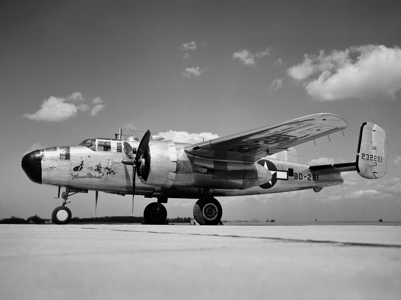
In 1946 the Lewis Flight Propulsion Laboratory became the NACA’s official icing research center. In addition to the Icing Research Tunnel, the lab possessed several aircraft modified for icing work, including a Consolidated B-24M Liberator and a North American XB-25E Mitchell, seen here. The XB-25E’s frequent engine fires allegedly resulted in its “Flamin’ Maimie” nickname. The aircraft’s nose art, visible in this photograph, includes a leather-jacketed mechanic with an extinguisher fleeing a fiery woman. North American developed the B-25 in the mid-1930s as a transport aircraft, but it was hurriedly reconfigured as a medium bomber for World War II. This XB-25E was a single prototype designed in 1942 specifically to test an exhaust gas ice prevention system developed by NACA researcher Lewis Rodert. The system circulated the engines’ hot bleed air to the wings, windshield, and tail. The XB-25E was utilized at the NACA’s Ames Aeronautical Laboratory for two years before being transferred to Cleveland in July 1944. NACA Lewis mechanics modified the aircraft further by installing electrical heating in the front fuselage, propellers, inboard sing, cowls, and antennae. Lewis pilots flew the B-24M and XB-25E into perilous weather conditions all across the country to study both deicing technologies and the physics of ice-producing clouds. These dangerous flights led to advances in weather sensing instruments and flight planning.
CAPE CANAVERAL, Fla. – At NASA’s Kennedy Space Center in Florida, smoke fills the air as the Project Morpheus prototype lander’s engine fires during a tether test at the north end of the Shuttle Landing Facility. During the test, the lander was lifted 20 feet by crane, and then ascended another 10 feet, maneuvered backwards 10 feet, and then flew forward. It will descend to its original position, landing at the end of the tether onto a transportable launch platform. Testing of the prototype lander was performed at NASA’s Johnson Space Center in Houston in preparation for tethered and free flight testing at Kennedy. The landing facility will provide the lander with the kind of field necessary for realistic testing, complete with rocks, craters and hazards to avoid. Morpheus utilizes an autonomous landing and hazard avoidance technology, or ALHAT, payload that will allow it to navigate to clear landing sites amidst rocks, craters and other hazards during its descent. Project Morpheus is being managed under the Advanced Exploration Systems, or AES, Division in NASA’s Human Exploration and Operations Mission Directorate. The efforts in AES pioneer new approaches for rapidly developing prototype systems, demonstrating key capabilities and validating operational concepts for future human missions beyond Earth orbit. For more information on Project Morpheus, visit http://morpheuslander.jsc.nasa.gov. Photo credit: NASA/Daniel Casper
CAPE CANAVERAL, Fla. – At NASA’s Kennedy Space Center in Florida, smoke fills the air as the Project Morpheus prototype lander’s engine fires during a tether test at the north end of the Shuttle Landing Facility. During the test, the lander was lifted 20 feet by crane, and then ascended another 10 feet, maneuvered backwards 10 feet, and then flew forward. It will descend to its original position, landing at the end of the tether onto a transportable launch platform. Testing of the prototype lander was performed at NASA’s Johnson Space Center in Houston in preparation for tethered and free flight testing at Kennedy. The landing facility will provide the lander with the kind of field necessary for realistic testing, complete with rocks, craters and hazards to avoid. Morpheus utilizes an autonomous landing and hazard avoidance technology, or ALHAT, payload that will allow it to navigate to clear landing sites amidst rocks, craters and other hazards during its descent. Project Morpheus is being managed under the Advanced Exploration Systems, or AES, Division in NASA’s Human Exploration and Operations Mission Directorate. The efforts in AES pioneer new approaches for rapidly developing prototype systems, demonstrating key capabilities and validating operational concepts for future human missions beyond Earth orbit. For more information on Project Morpheus, visit http://morpheuslander.jsc.nasa.gov. Photo credit: NASA/Daniel Casper

An artist's rendering of the air-breathing, hypersonic X-43B, the third and largest of NASA's Hyper-X series flight demonstrators, which could fly later this decade. Revolutionizing the way we gain access to space is NASA's primary goal for the Hypersonic Investment Area, managed for NASA by the Advanced Space Transportation Program at the Marshall Space Flight Center in Huntsville, Alabama. The Hypersonic Investment area, which includes leading-edge partners in industry and academia, will support future generation reusable vehicles and improved access to space. These technology demonstrators, intended for flight testing by decade's end, are expected to yield a new generation of vehicles that routinely fly about 100,000 feet above Earth's surface and reach sustained speeds in excess of Mach 5 (3,750 mph), the point at which "supersonic" flight becomes "hypersonic" flight. The flight demonstrators, the Hyper-X series, will be powered by air-breathing rocket or turbine-based engines, and ram/scramjets. Air-breathing engines, known as combined-cycle systems, achieve their efficiency gains over rocket systems by getting their oxygen for combustion from the atmosphere, as opposed to a rocket that must carry its oxygen. Once a hypersonic vehicle has accelerated to more than twice the speed of sound, the turbine or rockets are turned off, and the engine relies solely on oxygen in the atmosphere to burn fuel. When the vehicle has accelerated to more than 10 to 15 times the speed of sound, the engine converts to a conventional rocket-powered system to propel the craft into orbit or sustain it to suborbital flight speed. NASA's series of hypersonic flight demonstrators includes three air-breathing vehicles: the X-43A, X-43B and X-43C.
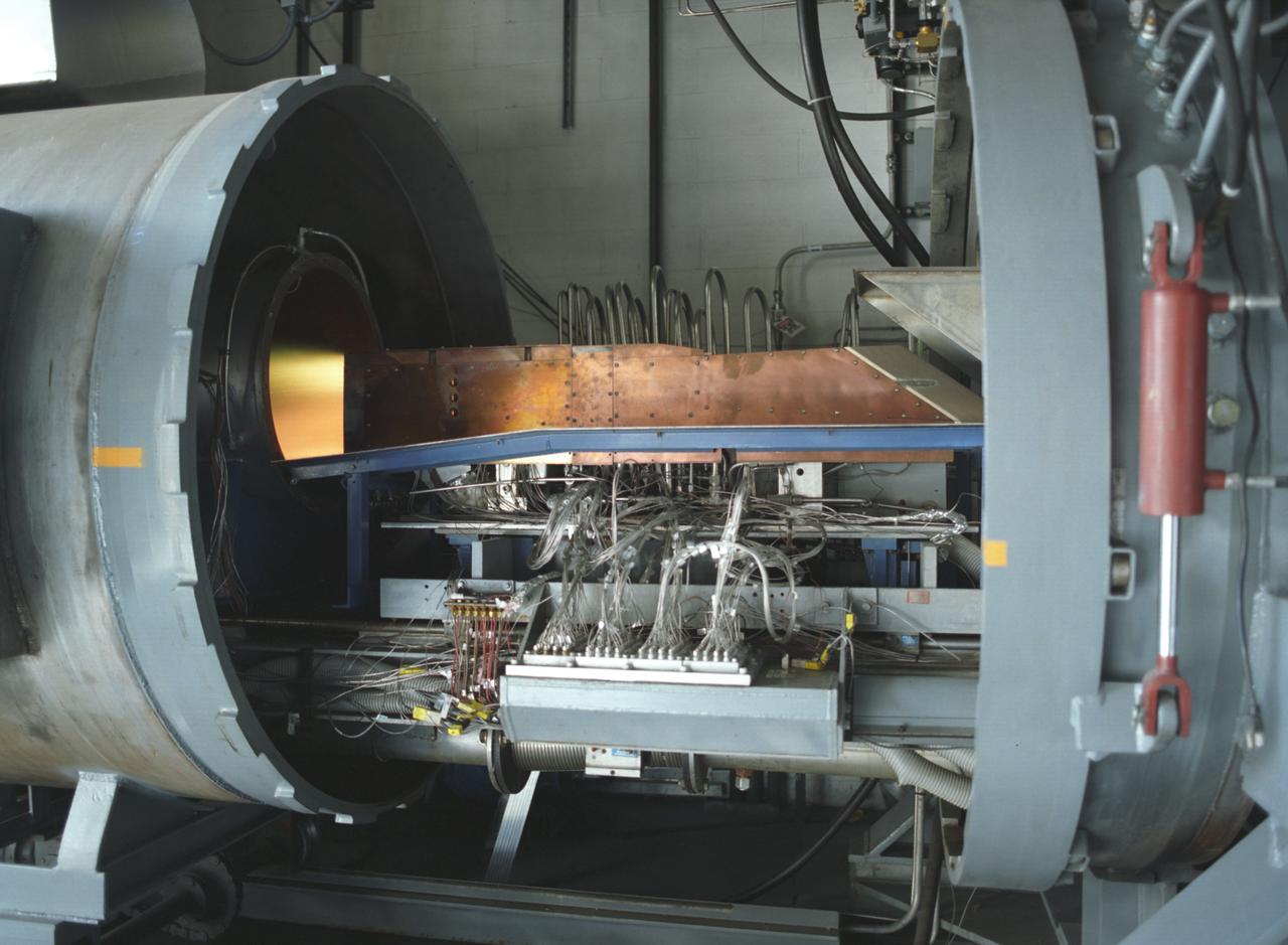
This photograph depicts an air-breathing rocket engine that completed an hour or 3,600 seconds of testing at the General Applied Sciences Laboratory in Ronkonkoma, New York. Referred to as ARGO by its design team, the engine is named after the mythological Greek ship that bore Jason and the Argonauts on their epic voyage of discovery. Air-breathing engines, known as rocket based, combined-cycle engines, get their initial take-off power from specially designed rockets, called air-augmented rockets, that boost performance about 15 percent over conventional rockets. When the vehicle's velocity reaches twice the speed of sound, the rockets are turned off and the engine relies totally on oxygen in the atmosphere to burn hydrogen fuel, as opposed to a rocket that must carry its own oxygen, thus reducing weight and flight costs. Once the vehicle has accelerated to about 10 times the speed of sound, the engine converts to a conventional rocket-powered system to propel the craft into orbit or sustain it to suborbital flight speed. NASA's Advanced SpaceTransportation Program at Marshall Space Flight Center, along with several industry partners and collegiate forces, is developing this technology to make space transportation affordable for everyone from business travelers to tourists. The goal is to reduce launch costs from today's price tag of $10,000 per pound to only hundreds of dollars per pound. NASA's series of hypersonic flight demonstrators currently include three air-breathing vehicles: the X-43A, X-43B and X-43C.
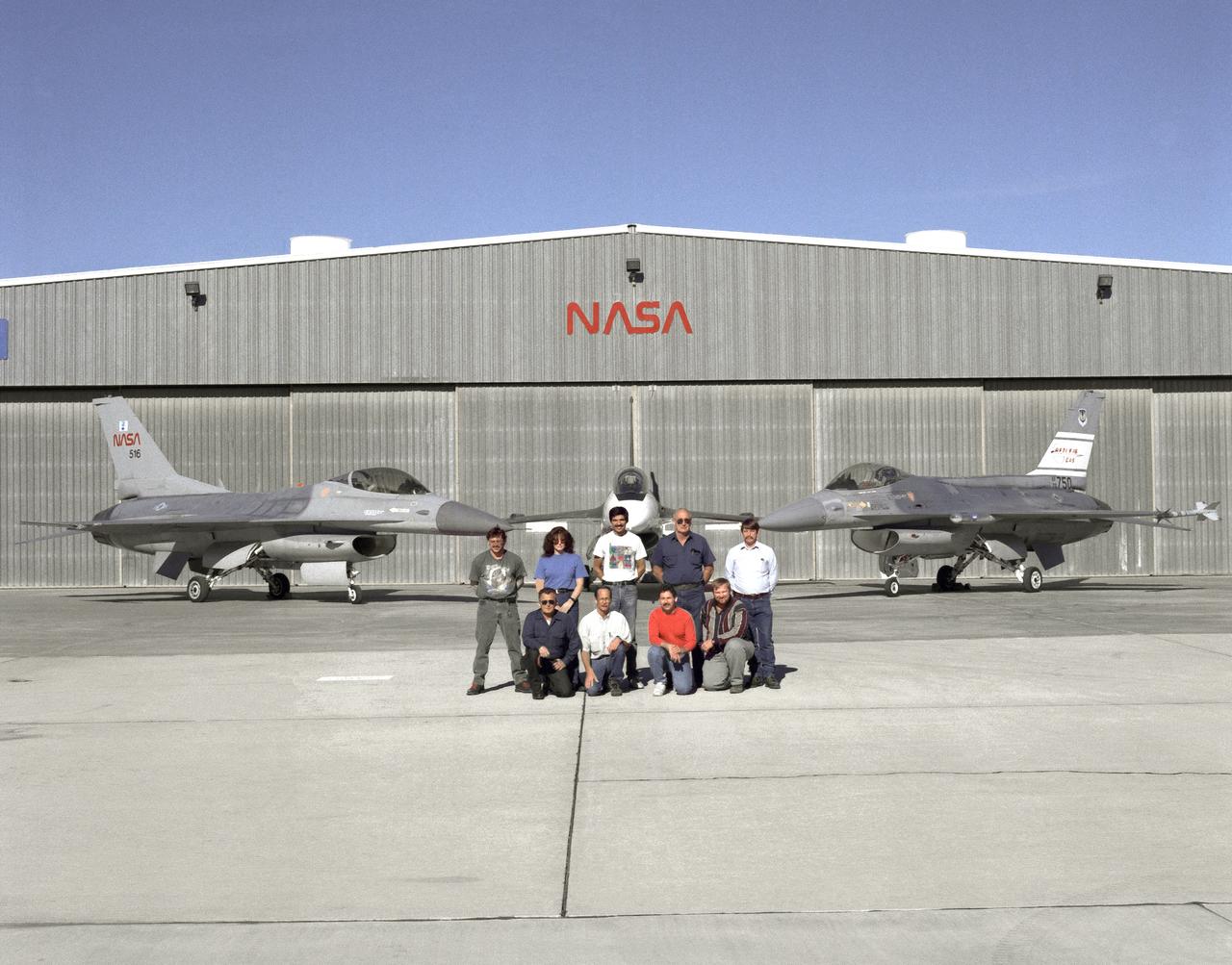
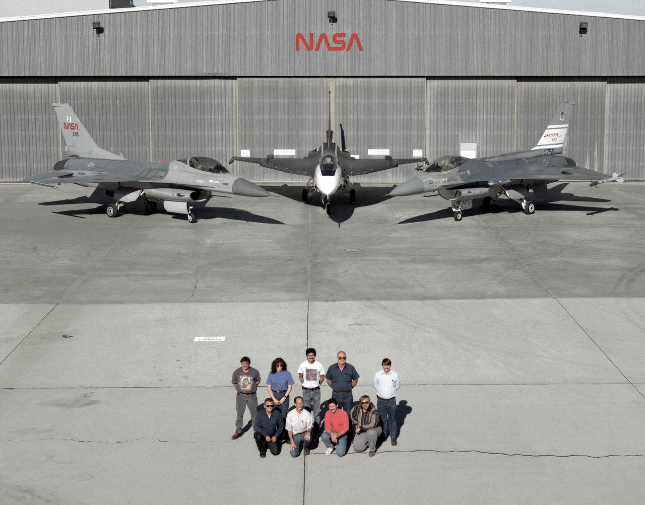
The support crew for the F-16A, the F-16XL no. 1, and the F-16 AFTI are, top row, left to right: Randy Weaver; mechanic, Susan Ligon; mechanic, Bob Garcia; Crew Chief, Rich Kelly; mechanic, Dale Edminister; Avionics Technician. Bottom row, left to right, Art Cope; mechanic, John Huffman; Avionics Technician, Jaime Garcia; Avionics Technician, Don Griffith, Avionics Tech. Co-op student. The F-16A (NASA 516), the only civil registered F-16 in existence, was transferred to Dryden from Langley, and was primarily used in engine tests and for parts. It was subsequently transfered from Dryden. The single-seat F-16XL no. 1 (NASA 849) was most recently used in the Cranked-Arrow Wing Aerodynamics Project (CAWAP) to test boundary layer pressures and distribution. Previously it had been used in a program to investigate the characteristics of sonic booms for NASA's High Speed Research Program. Data from the program will be used in the development of a high speed civilian transport. During the series of sonic boom research flights, the F-16XL was used to probe the shock waves being generated by a NASA SR-71 and record their shape and intensity. The Advanced Fighter Technology Integration (AFTI) F-16 was used to develop and demonstrate technologies to improve navigation and a pilot's ability to find and destroy enemy ground targets day or night, including adverse weather. Earlier research in the joint NASA-Air Force AFTI F-16 program demonstrated voice actuated controls, helmet-mounted sighting and integration of forward-mounted canards with the standard flight control system to achieve uncoupled flight.
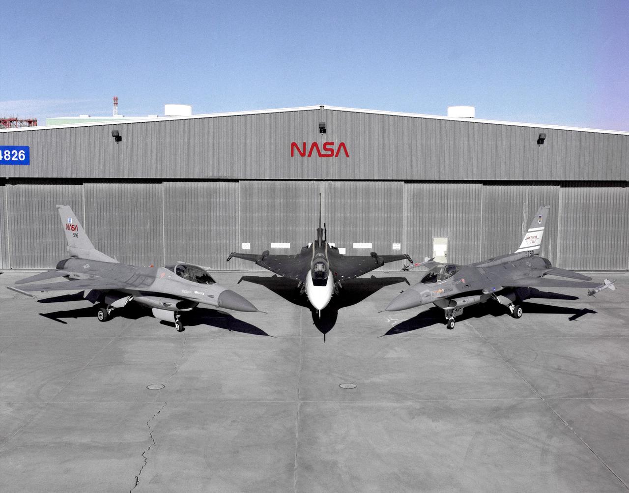
Photographed outside their hangar at the Dryden Flight Research Center, Edwards, California, part of Dryden's F-16 fleet is, left to right; an F-16A, the F-16XL no. 1, and the F-16 AFTI. The F-16A (NASA 516), the only civil registered F-16 in existence, was transferred to Dryden from Langley, and was primarily used in engine tests and for parts. It was subsequently transfered from Dryden. The single-seat F-16XL no. 1 (NASA 849) was most recently used in the Cranked-Arrow Wing Aerodynamics Project (CAWAP) to test boundary layer pressures and distribution. Previously it had been used in a program to investigate the characteristics of sonic booms for NASA's High Speed Research Program. Data from the program will be used in the development of a high speed civilian transport. During the series of sonic boom research flights, the F-16XL was used to probe the shock waves being generated by a NASA SR-71 and record their shape and intensity. The Advanced Fighter Technology Integration (AFTI) F-16 was used to develop and demonstrate technologies to improve navigation and a pilot's ability to find and destroy enemy ground targets day or night, including adverse weather. Earlier research in the joint NASA-Air Force AFTI F-16 program demonstrated voice actuated controls, helmet-mounted sighting and integration of forward-mounted canards with the standard flight control system to achieve uncoupled flight.
The support crew for the F-16A, the F-16XL no. 1, and the F-16 AFTI are, top row, left to right: Randy Weaver; mechanic, Susan Ligon; mechanic, Bob Garcia; Crew Chief, Rich Kelly; mechanic, Dale Edminister; Avionics Technician. Bottom row, left to right, Art Cope; mechanic, John Huffman; Avionics Technician, Jaime Garcia; Avionics Technician, Don Griffith, Avionics Tech. Co-op student. The F-16A (NASA 516), the only civil registered F-16 in existence, was transferred to Dryden from Langley, and was primarily used in engine tests and for parts. It was subsequently transfered from Dryden. The single-seat F-16XL no. 1 (NASA 849) was most recently used in the Cranked-Arrow Wing Aerodynamics Project (CAWAP) to test boundary layer pressures and distribution. Previously it had been used in a program to investigate the characteristics of sonic booms for NASA's High Speed Research Program. Data from the program will be used in the development of a high speed civilian transport. During the series of sonic boom research flights, the F-16XL was used to probe the shock waves being generated by a NASA SR-71 and record their shape and intensity. The Advanced Fighter Technology Integration (AFTI) F-16 was used to develop and demonstrate technologies to improve navigation and a pilot's ability to find and destroy enemy ground targets day or night, including adverse weather. Earlier research in the joint NASA-Air Force AFTI F-16 program demonstrated voice actuated controls, helmet-mounted sighting and integration of forward-mounted canards with the standard flight control system to achieve uncoupled flight.
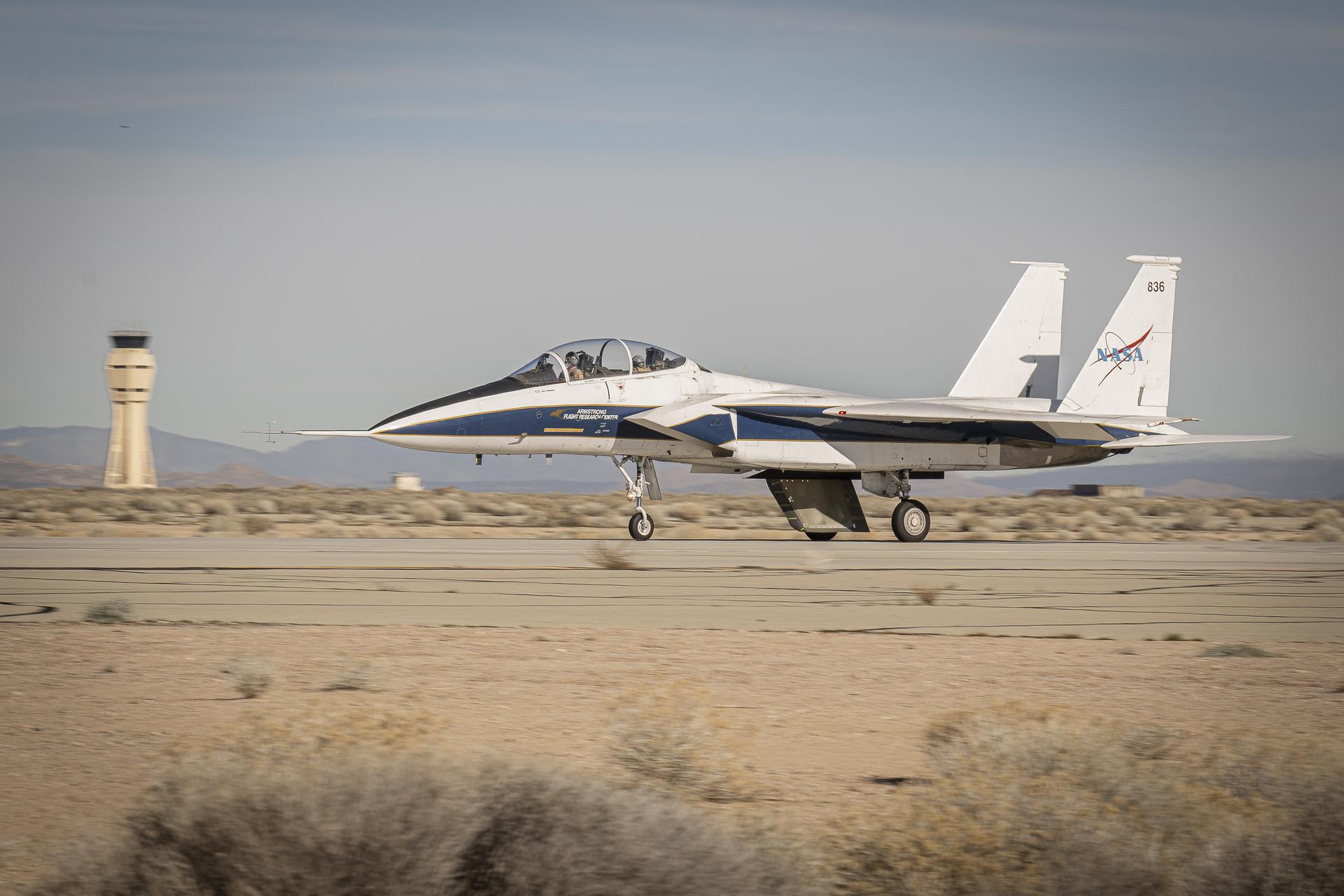
NASA’s Cross Flow Attenuated Natural Laminar Flow test article is mounted beneath the agency’s F-15 research aircraft ahead of the design’s high-speed taxi test on Tuesday, Jan. 12, 2026, at NASA’s Armstrong Flight Research Center in Edwards, California. The 3-foot-tall scale model is designed to increase a phenomenon known as laminar flow and reduce drag, improving efficiency in large, swept wings like those found on most commercial aircraft.
NASA’s Cross Flow Attenuated Natural Laminar Flow test article is mounted beneath the agency’s F-15 research aircraft ahead of the design’s high-speed taxi test on Tuesday, Jan. 12, 2026, at NASA’s Armstrong Flight Research Center in Edwards, California. The 3-foot-tall scale model is designed to increase a phenomenon known as laminar flow and reduce drag, improving efficiency in large, swept wings like those found on most commercial aircraft.
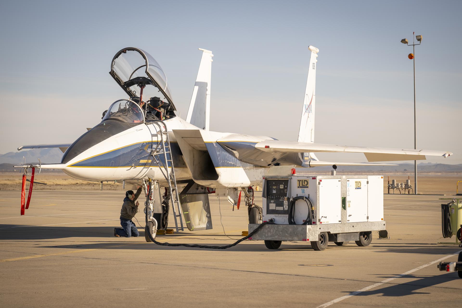
NASA ground crew prepares the agency’s F-15 research aircraft and Cross Flow Attenuated Natural Laminar Flow (CATNLF) test article ahead of its first high-speed taxi test on Tuesday, Jan. 12, 2026, at NASA’s Armstrong Flight Research Center in Edwards, California. The CATNLF design aims to reduce drag on wing surfaces to improve efficiency and, in turn, reduce fuel burn.
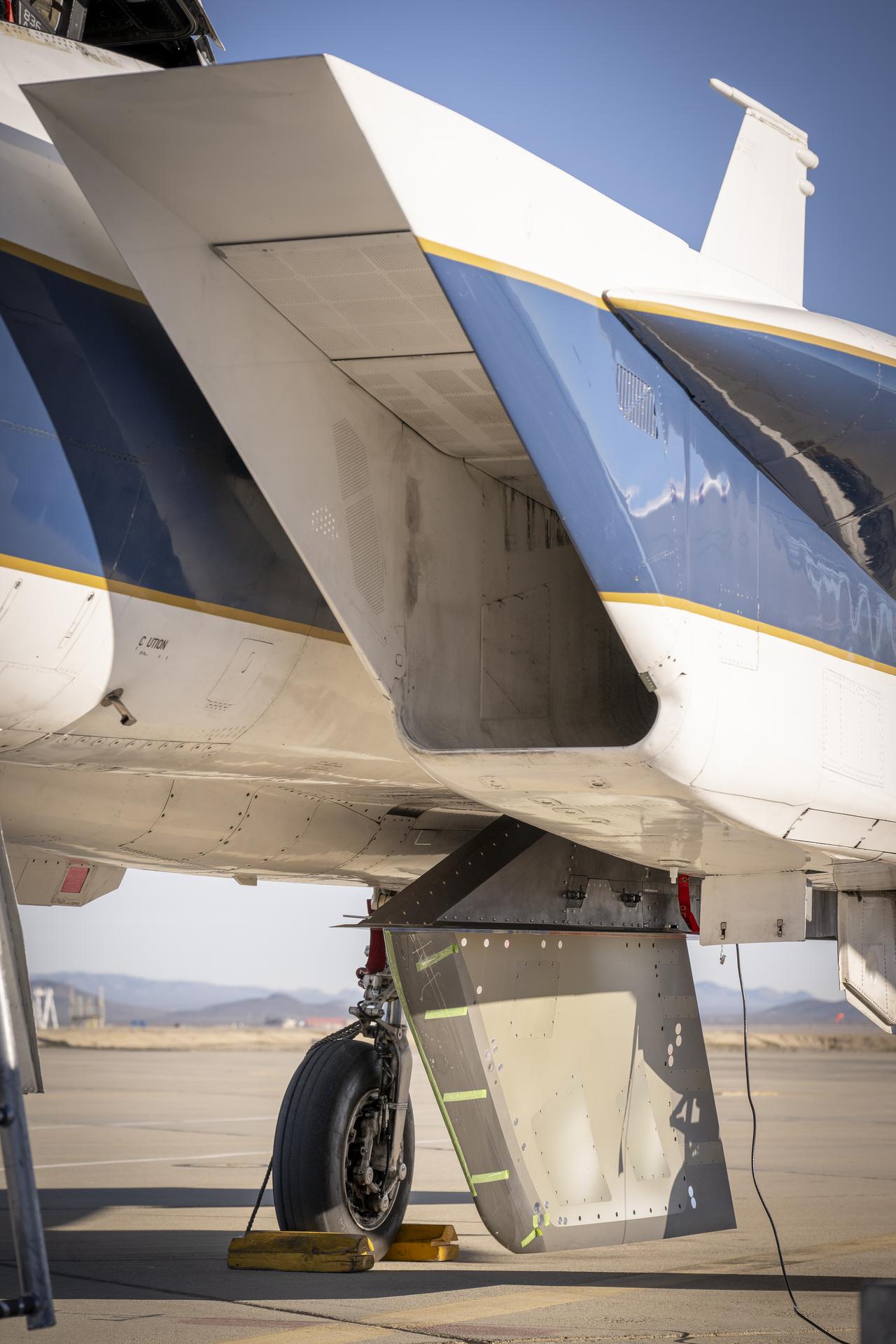
NASA’s Cross Flow Attenuated Natural Laminar Flow test article is mounted beneath the agency’s F-15 research aircraft ahead of the design’s high-speed taxi test on Tuesday, Jan. 12, 2026, at NASA’s Armstrong Flight Research Center in Edwards, California. The 3-foot-tall scale model is designed to increase a phenomenon known as laminar flow and reduce drag, improving efficiency in large, swept wings like those found on most commercial aircraft.
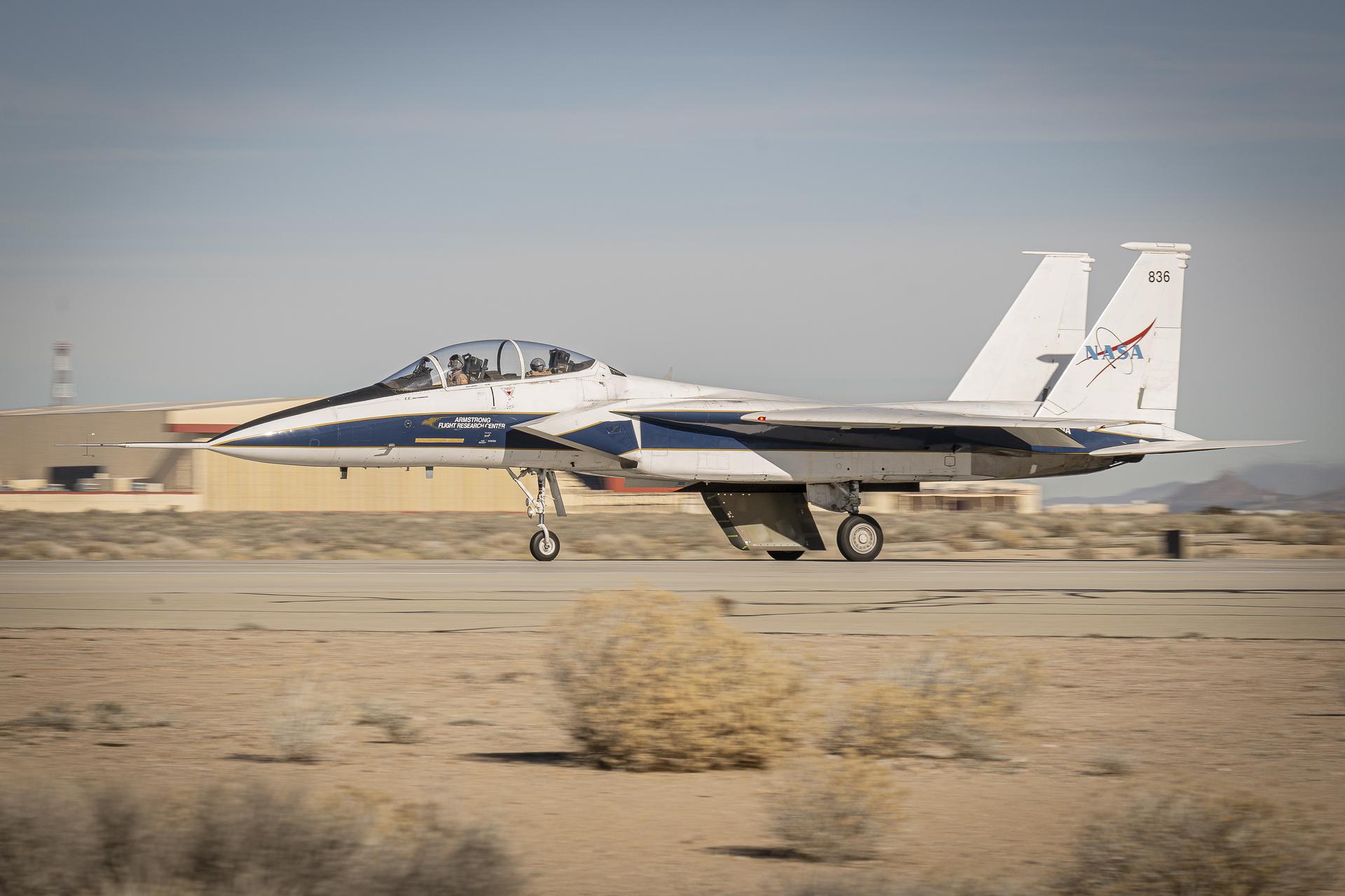
NASA’s Cross Flow Attenuated Natural Laminar Flow (CATNLF) scale model completes its first major milestone – high-speed taxi test – Tuesday, Jan. 12, 2026, at Edwards Air Force Base in California. NASA’s F-15 research aircraft, with the 3-foot-tall test article mounted on its underside, reached speeds of approximately 144 mph during testing. If successful, the technology could be applied to future commercial aircraft to improve efficiency and potentially reduce fuel consumption.
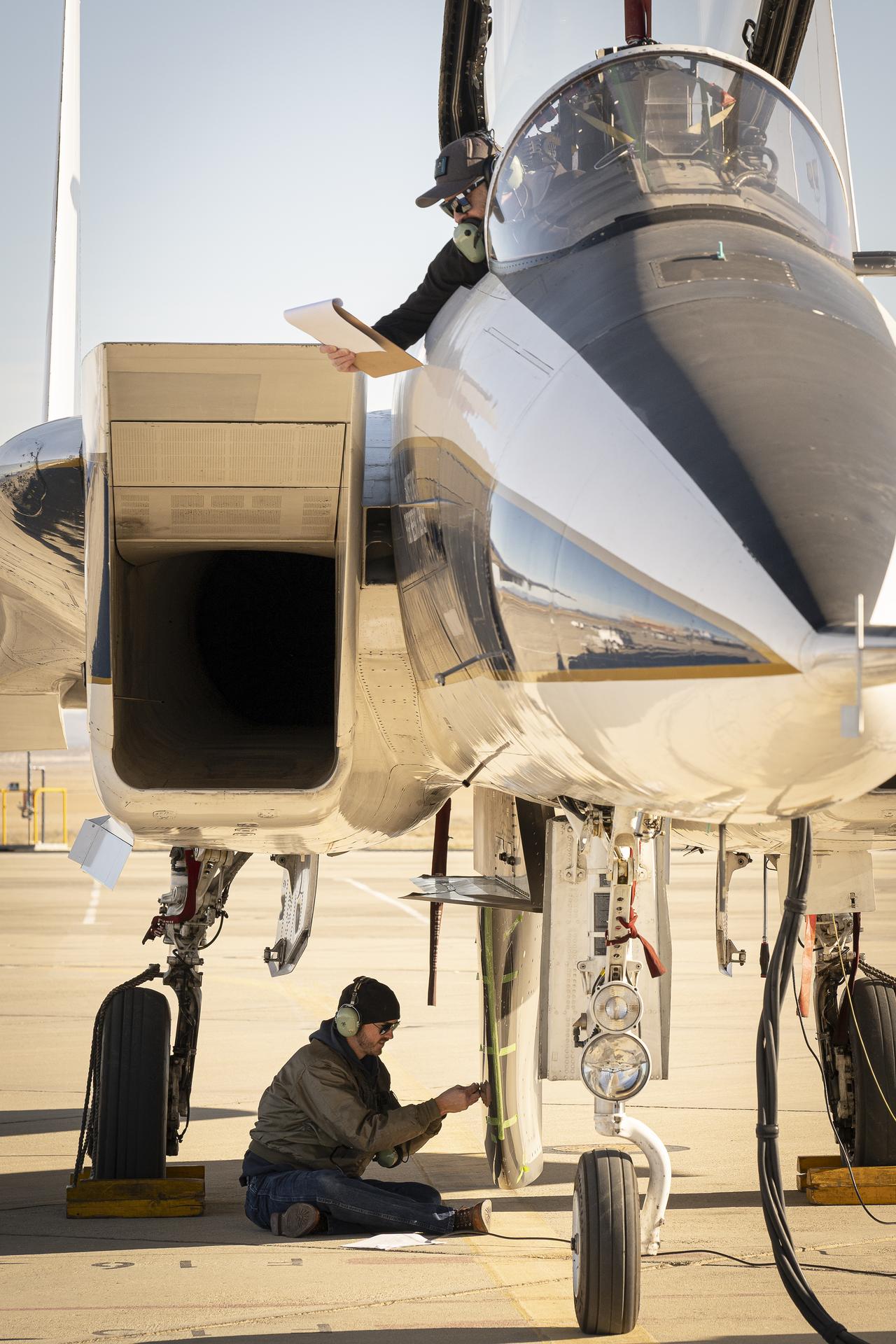
NASA ground crew prepares the agency’s F-15 research aircraft and Cross Flow Attenuated Natural Laminar Flow (CATNLF) test article ahead of its first high-speed taxi test on Tuesday, Jan. 12, 2026, at NASA’s Armstrong Flight Research Center in Edwards, California. The CATNLF design aims to reduce drag on wing surfaces to improve efficiency and, in turn, reduce fuel burn.
NASA’s Cross Flow Attenuated Natural Laminar Flow (CATNLF) scale model completes its first major milestone – high-speed taxi test – Tuesday, Jan. 12, 2026, at Edwards Air Force Base in California. NASA’s F-15 research aircraft, with the 3-foot-tall test article mounted on its underside, reached speeds of approximately 144 mph during testing. If successful, the technology could be applied to future commercial aircraft to improve efficiency and potentially reduce fuel consumption.
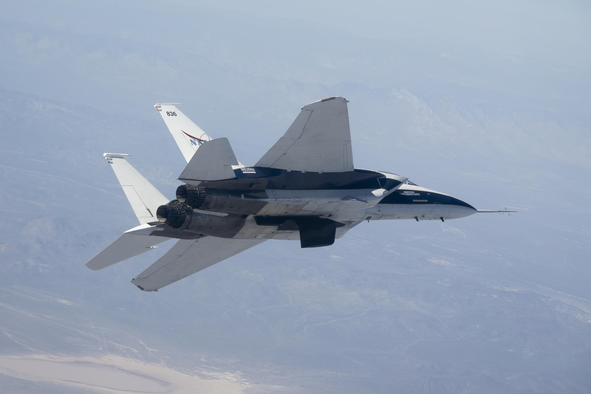
NASA’s Crossflow Attenuated Natural Laminar Flow (CATNLF) scale-model wing flies on a NASA F-15 research jet during a test flight from NASA’s Armstrong Flight Research Center in Edwards, California. The CATNLF technology is designed to maintain smooth airflow, known as laminar flow. NASA will continue flight tests to collect data that validates the CATNLF design and its potential to improve laminar flow, reducing drag and lowering fuel costs for future commercial aircraft.
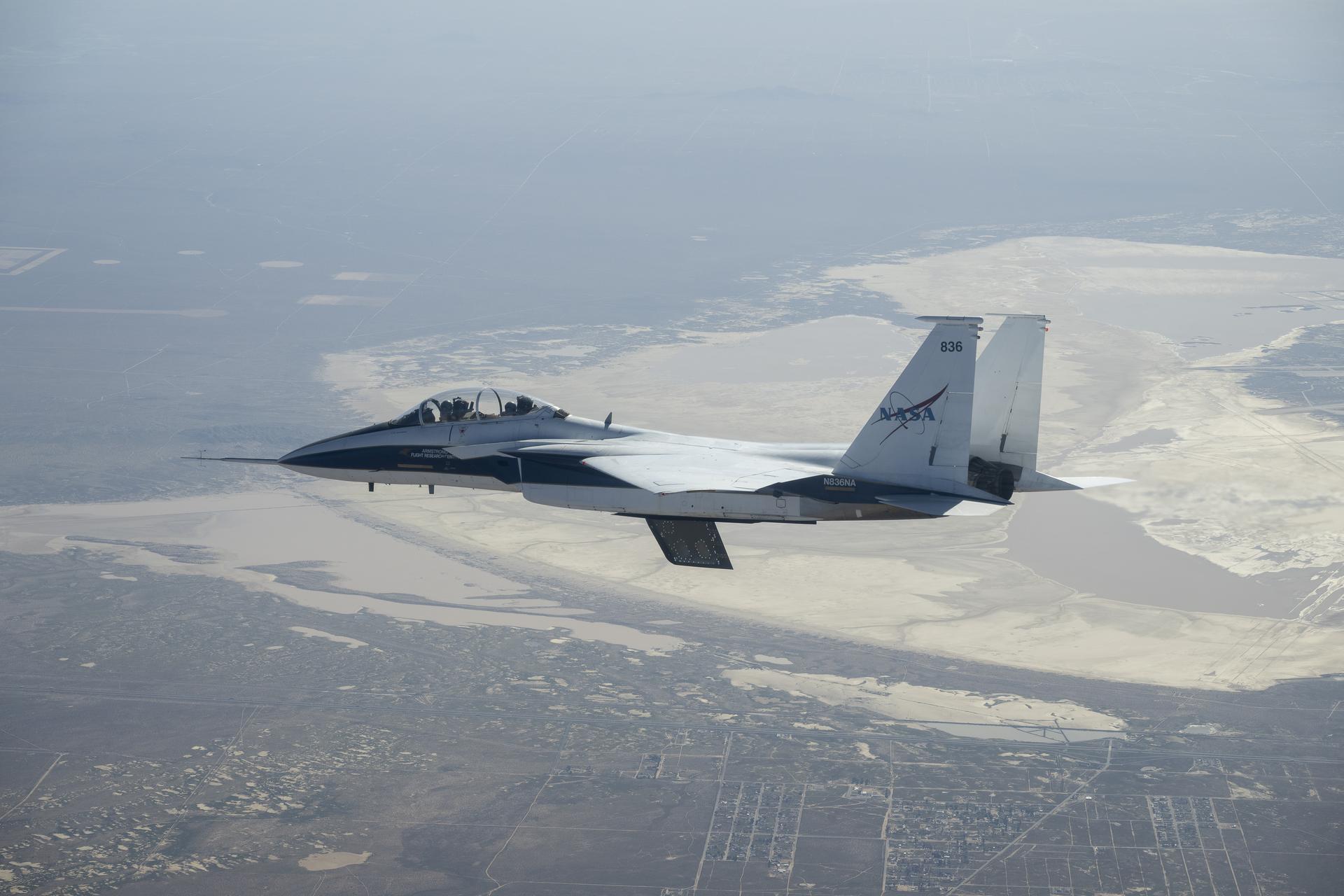
NASA’s Crossflow Attenuated Natural Laminar Flow (CATNLF) scale-model wing flies for the first time on a NASA F-15 research jet during a test flight from NASA’s Armstrong Flight Research Center in Edwards, California. The 75-minute flight confirmed the aircraft could maneuver safely with the approximately 3-foot-tall test article mounted beneath it. NASA will continue flight tests to collect data that validates the CATNLF design and its potential to improve laminar flow, reducing drag and lowering fuel costs for future commercial aircraft.
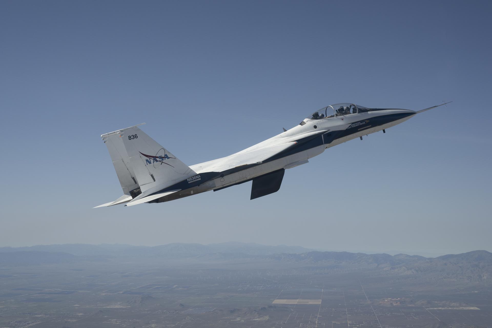
NASA’s Crossflow Attenuated Natural Laminar Flow (CATNLF) scale-model wing flies for the first time on a NASA F-15 research jet during a test flight from NASA’s Armstrong Flight Research Center in Edwards, California. The 75-minute flight confirmed the aircraft could maneuver safely with the approximately 3-foot-tall test article mounted beneath it. NASA will continue flight tests to collect data that validates the CATNLF design and its potential to improve laminar flow, reducing drag and lowering fuel costs for future commercial aircraft.