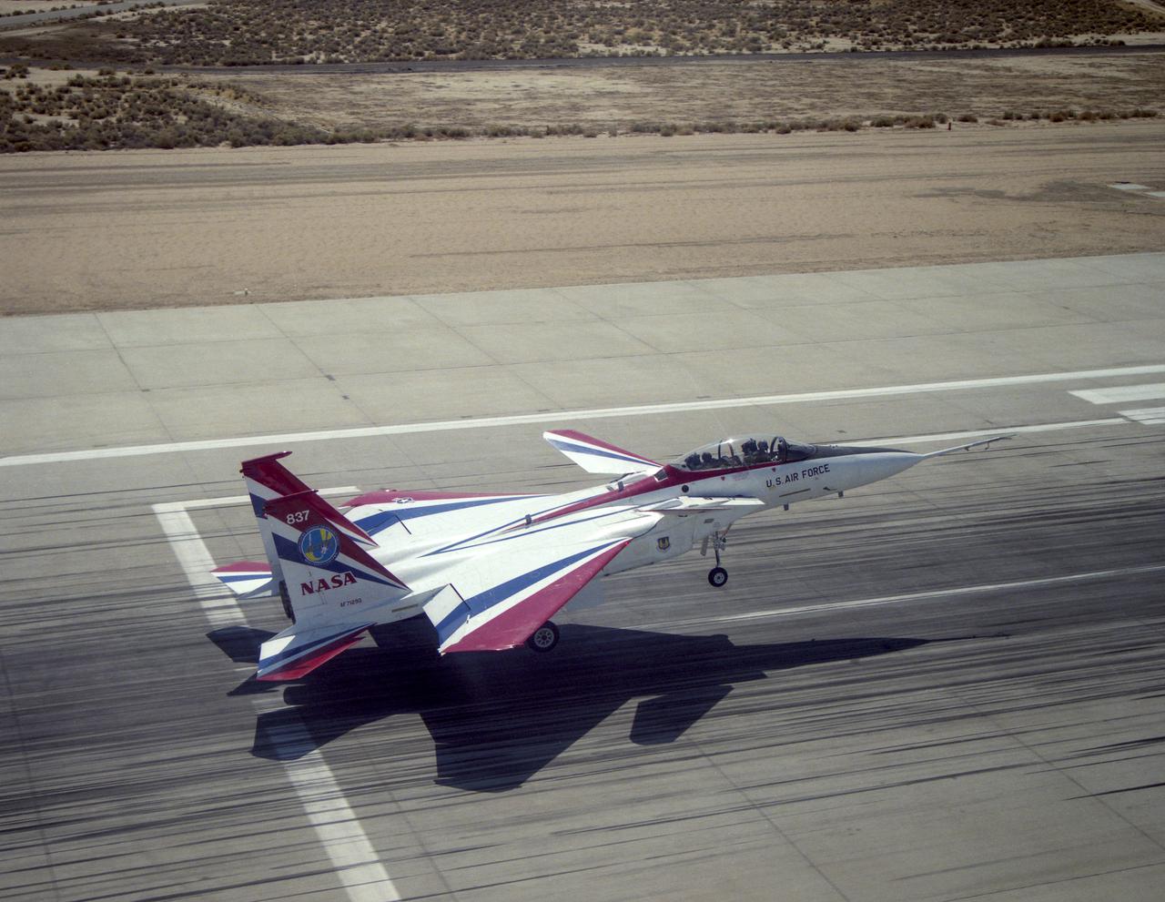
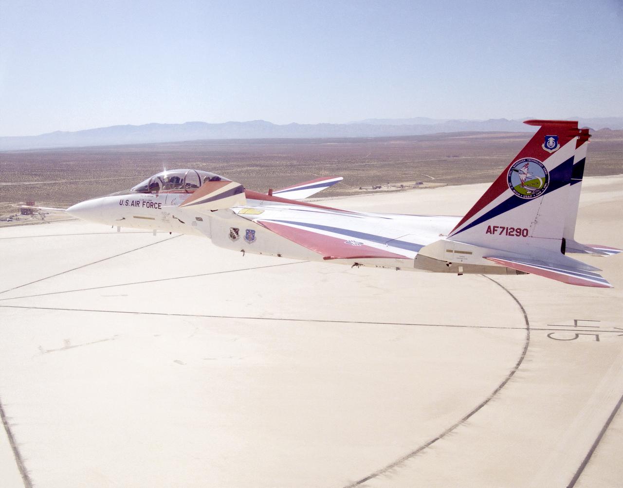
The F-15 Advanced Controls Technology for Integrated Vehicles, the first pre-production F-15B, shows its canards. Less obvious are the multi-axis thrust vectoring exhaust nozzles.

F-15B ACTIVE in flight
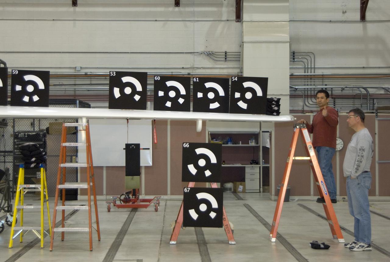
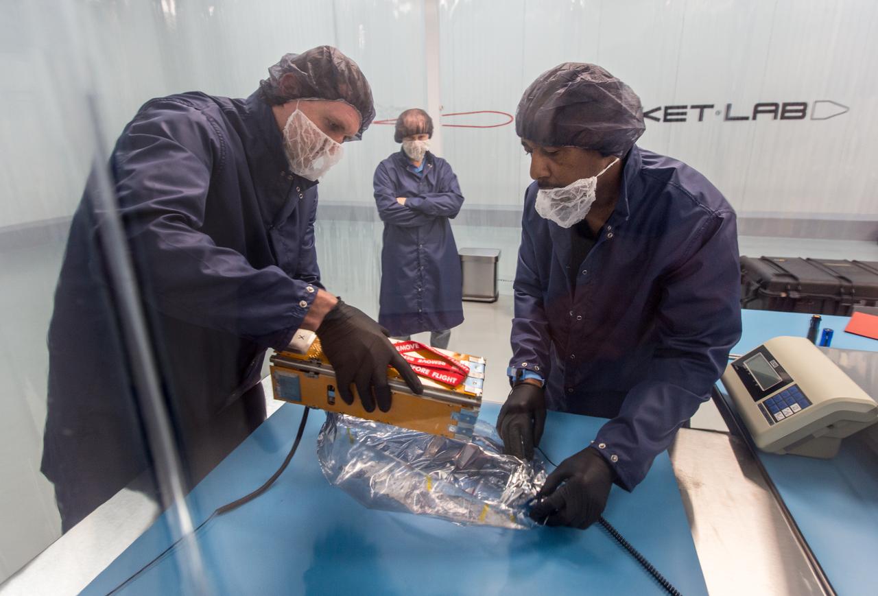
NASA engineer Larry Hudson and Ikhana ground crew member James Smith work on a ground validation test with new fiber optic sensors that led to validation flights on the Ikhana aircraft. NASA Dryden Flight Research Center is evaluating an advanced fiber optic-based sensing technology installed on the wings of NASA's Ikhana aircraft. The fiber optic system measures and displays the shape of the aircraft's wings in flight. There are other potential safety applications for the technology, such as vehicle structural health monitoring. If an aircraft structure can be monitored with sensors and a computer can manipulate flight control surfaces to compensate for stresses on the wings, structural control can be established to prevent situations that might otherwise result in a loss of control.
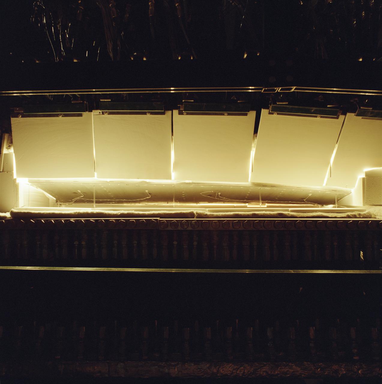
The X-37 advanced technology demonstrator flaperon unit was one of the first ever thermal and mechanical qualification tests of a carbon-carbon control surface designed for space flight. The test also featured extensive use of high-temperature fiber optic strain sensors. Peak temperatures reached 2,500 degrees Fahrenheit.
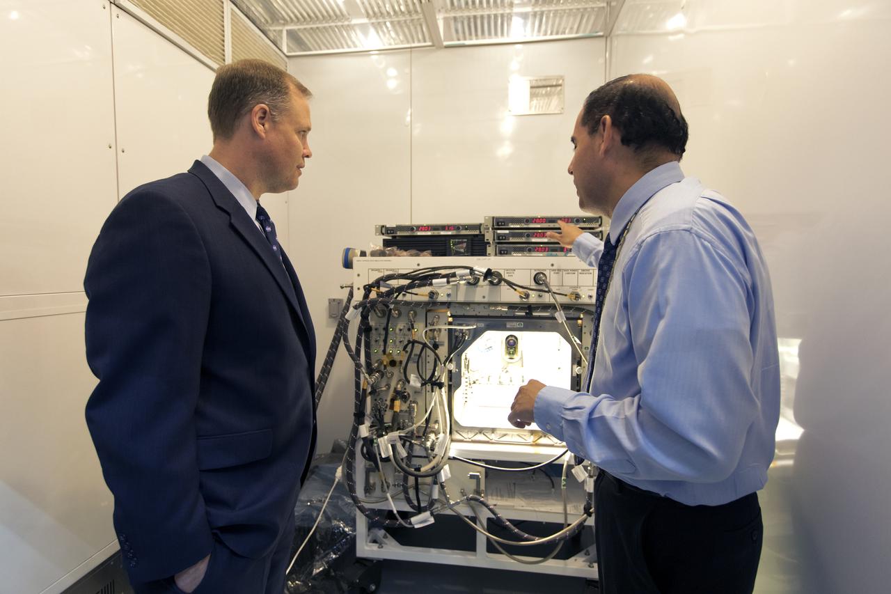
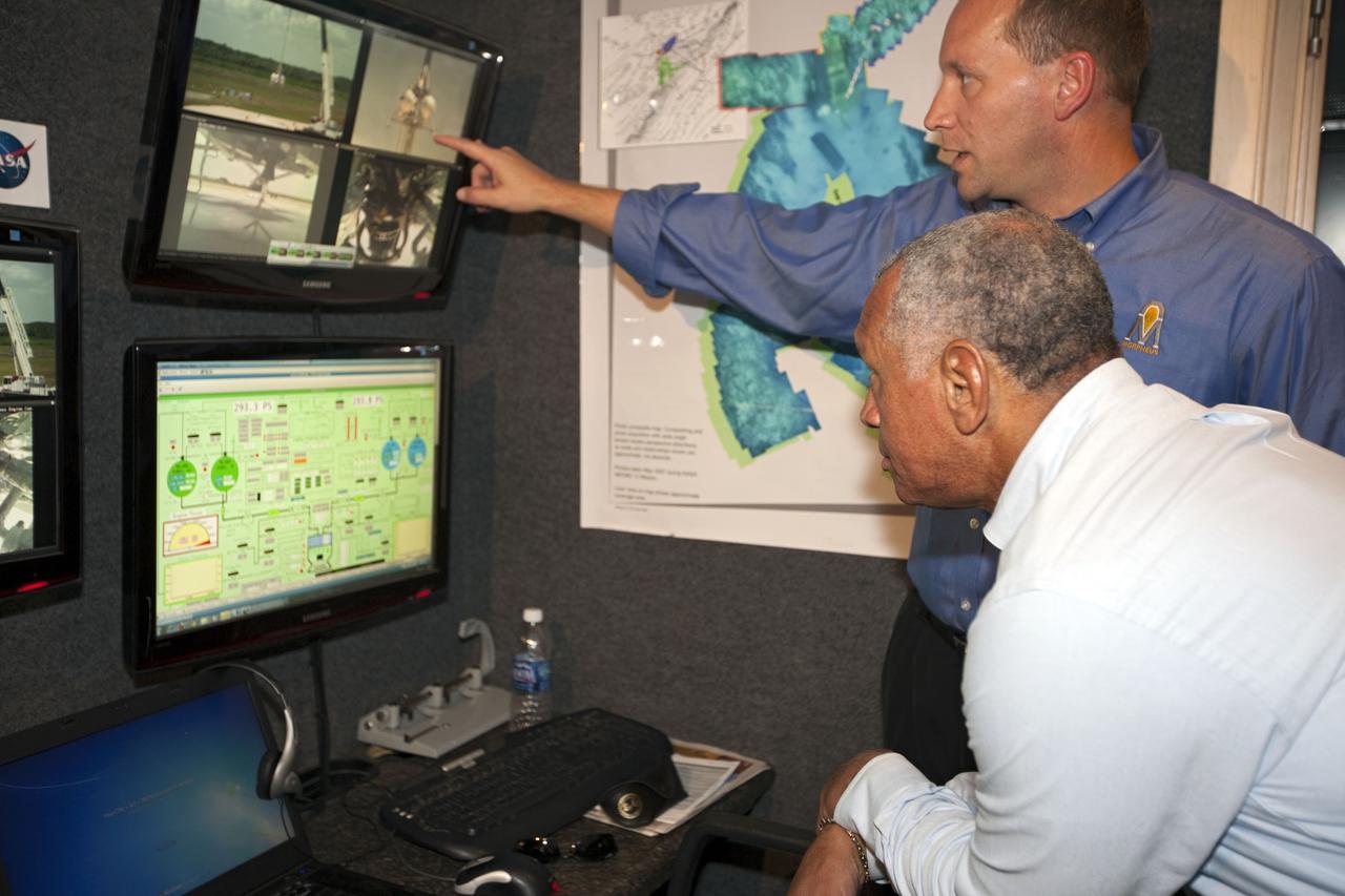
NASA Administrator Jim Bridenstine, left, tours the Space Station Processing Facility at NASA's Kennedy Space Center in Florida, on Aug. 7, 2018. Bryan Onate, at right, Advanced Plant Habitat (APH) project manager, explains a component of the APH control system. Bridenstine also received updates on research and technology accomplishments.

A NASA F/A-18, specially modified to test the newest and most advanced system technologies, on its first research flight on May 21, 1993, at NASA's Dryden Flight Research Facility, Edwards, California. Flown by Dryden in a multi-year, joint NASA/DOD/industry program, the F/A-18 former Navy fighter was modified into a unique Systems Research Aircraft (SRA) to investigate a host of new technologies in the areas of flight controls, airdata sensing and advanced computing. The primary goal of the SRA program was to validate through flight research cutting-edge technologies which could benefit future aircraft and spacecraft by improving efficiency and performance, reducing weight and complexity, with a resultant reduction on development and operational costs.

F-15B ACTIVE in flight
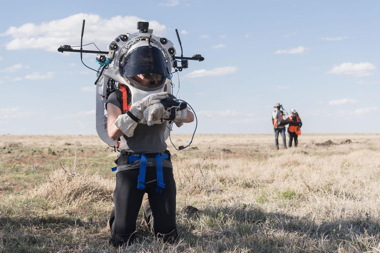
NASA astronaut Kate Rubins uses the hand controller on her wrist to display information while wearing the Joint AR (Joint Augmented Reality Visual Informatics System) display during an advanced technology run in the San Francisco Volcanic Field in Northern Arizona on May 21, 2024. The suit display features include navigation, photo capture, graphical format of consumables, procedure viewing, mission control updates, and other augmented reality cues and graphics. The team successfully tested navigation displays using data from four different data streams: GPS (Global Positioning System)/IMU (Inertial Measurement Unit), camera/IMU, LiDAR (Light Detection and Ranging), and static maps. Technology like this may be used for future Artemis missions to augment mission control communication and help guide crew back to the lunar lander. Credit: NASA/Josh Valcarcel
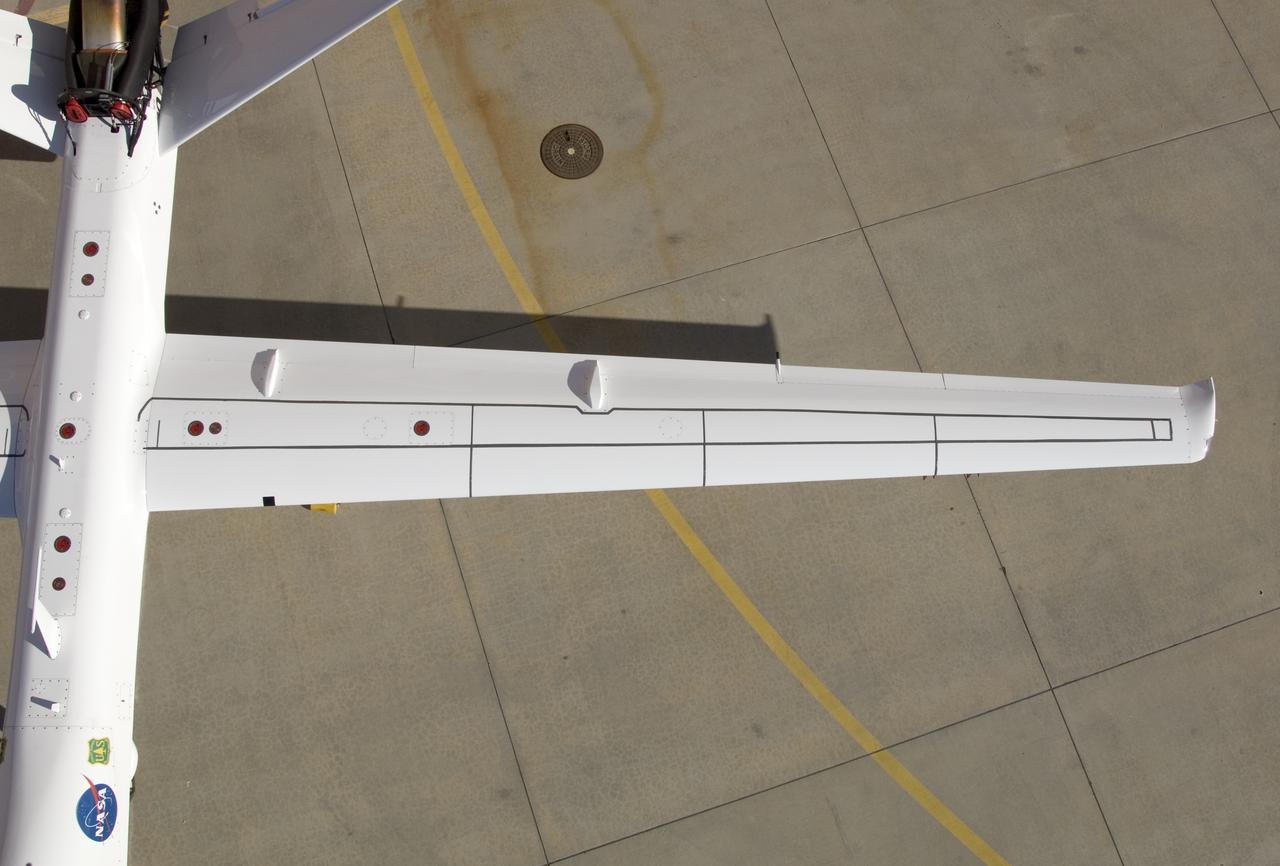
Although the new fiber optic sensors on the Ikhana, which are located on fibers that are the diameter of a human hair, are not visible, the sealant used to cover them can be seen in this view from above the left wing. NASA Dryden Flight Research Center is evaluating an advanced fiber optic-based sensing technology installed on the wings of NASA's Ikhana aircraft. The fiber optic system measures and displays the shape of the aircraft's wings in flight. There are other potential safety applications for the technology, such as vehicle structural health monitoring. If an aircraft structure can be monitored with sensors and a computer can manipulate flight control surfaces to compensate for stresses on the wings, structural control can be established to prevent situations that might otherwise result in a loss of control.
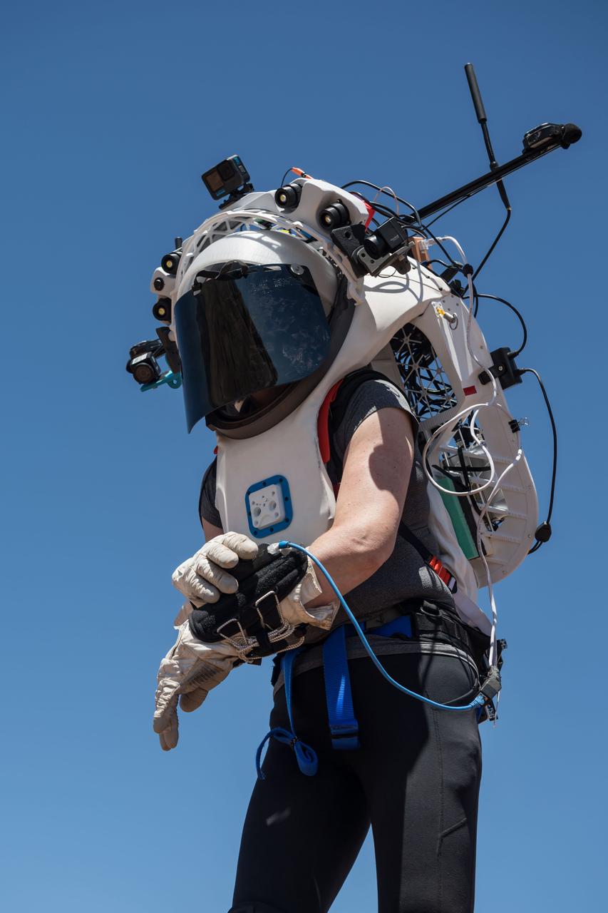
NASA astronaut Kate Rubins uses the hand controller on her wrist to display information while wearing the Joint AR (Joint Augmented Reality Visual Informatics System) display during an advanced technology run in the San Francisco Volcanic Field in Northern Arizona on May 19, 2024. The suit display features include navigation, photo capture, graphical format of consumables, procedure viewing, mission control updates, and other augmented reality cues and graphics. The team successfully tested navigation displays using data from four different data streams: GPS (Global Positioning System)/IMU (Inertial Measurement Unit), camera/IMU, LiDAR (Light Detection and Ranging), and static maps. Technology like this may be used for future Artemis missions to augment mission control communication and help guide crew back to the lunar lander. Credit: NASA/Josh Valcarcel
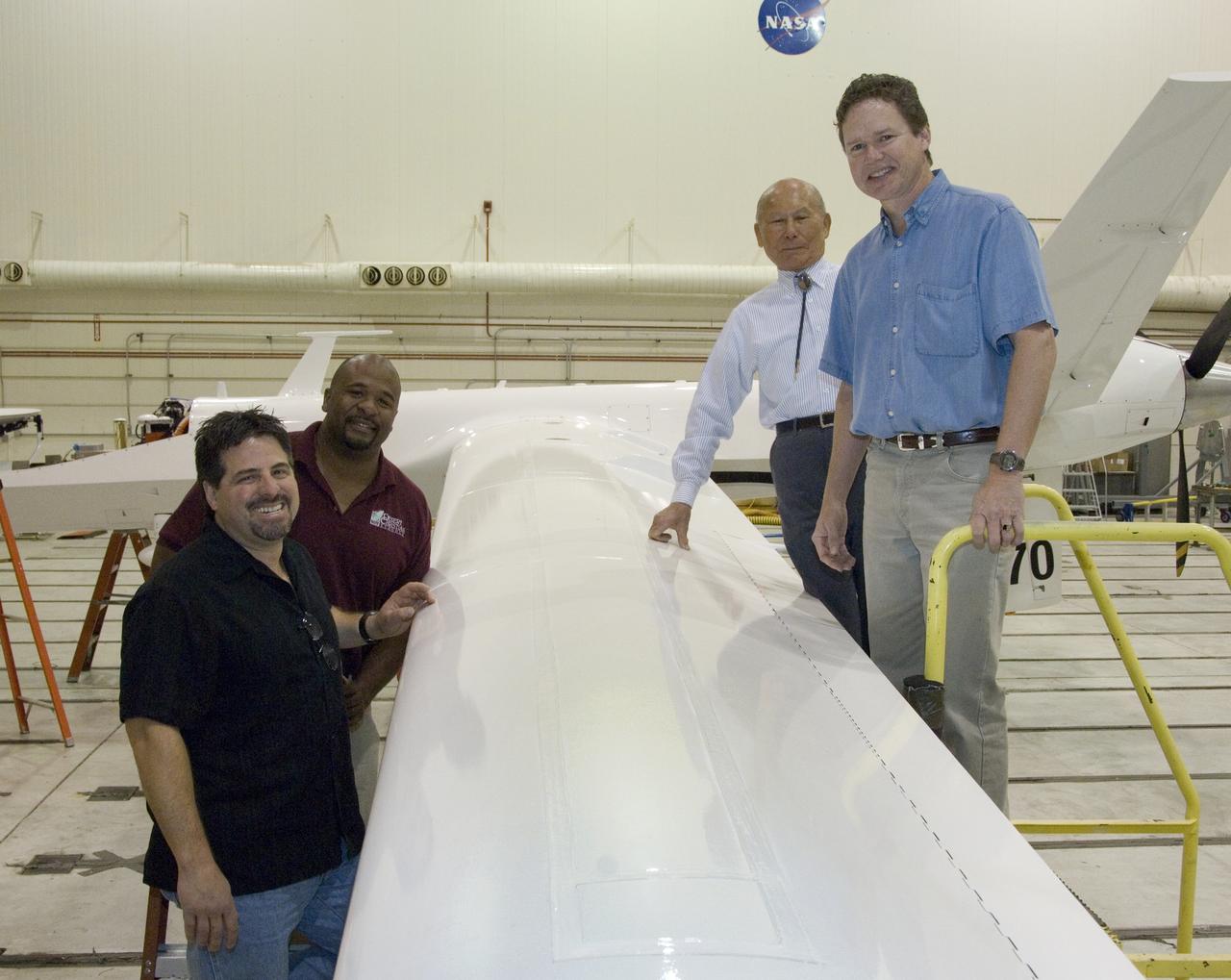
Ikhana fiber optic wing shape sensor team: clockwise from left, Anthony "Nino" Piazza, Allen Parker, William Ko and Lance Richards. The sensors, located along a fiber the thickness of a human hair, aren't visible in the center of the Ikhana aircraft's left wing. NASA Dryden Flight Research Center is evaluating an advanced fiber optic-based sensing technology installed on the wings of NASA's Ikhana aircraft. The fiber optic system measures and displays the shape of the aircraft's wings in flight. There are other potential safety applications for the technology, such as vehicle structural health monitoring. If an aircraft structure can be monitored with sensors and a computer can manipulate flight control surfaces to compensate for stresses on the wings, structural control can be established to prevent situations that might otherwise result in a loss of control.
F-15B ACTIVE in flight over lakebed
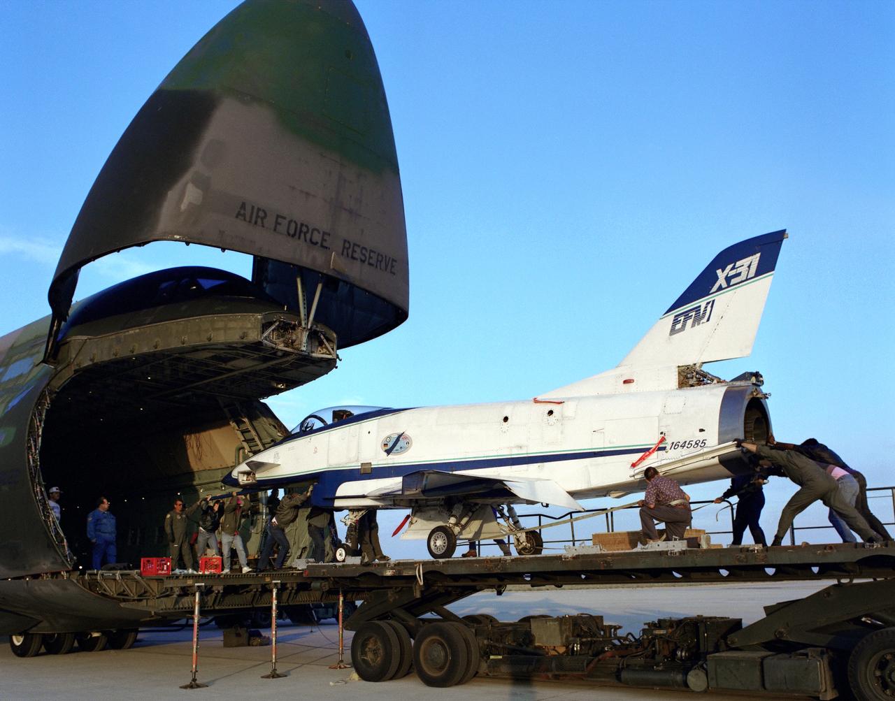
The X-31 Enhanced Fighter Maneuverability Technology Demonstrator Aircraft, based at the NASA Dryden Flight Research Center, Edwards, California, begins rolling aboard an Air Force Reserve C-5 transport which ferried it on May 22, 1995 to Europe where it was flown in the Paris Air Show in June 1995. To fit in the C-5 the right wing of the X-31 had to be removed. At the air show, the X-31 demonstrated the value of using thrust vectoring (directing engine exhaust flow) coupled with advanced flight control systems to provide controlled flight at very high angles of attack.
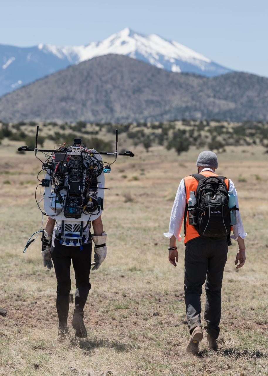
NASA astronaut Kate Rubins walks through the lunar-like landscape wearing the Joint AR (Joint Augmented Reality Visual Informatics System) display during an advanced technology run in the San Francisco Volcanic Field in Northern Arizona on May 19, 2024. The suit display features include navigation, photo capture, graphical format of consumables, procedure viewing, mission control updates, and other augmented reality cues and graphics. The team successfully tested navigation displays using data from four different data streams: GPS (Global Positioning System)/IMU (Inertial Measurement Unit), camera/IMU, LiDAR (Light Detection and Ranging), and static maps. Technology like this may be used for future Artemis missions to augment mission control communication and help guide crew back to the lunar lander. Credit: NASA/Josh Valcarcel
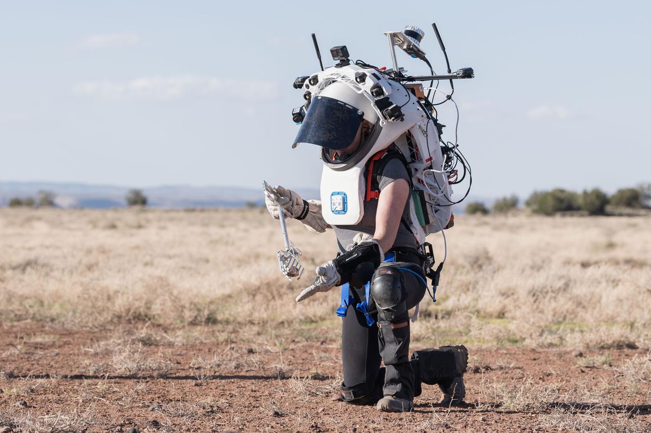
NASA astronaut Kate Rubins uses tongs to pick up a geologic sample while wearing the Joint AR (Joint Augmented Reality Visual Informatics System) display during an advanced technology run in the San Francisco Volcanic Field in Northern Arizona on May 21, 2024. The suit display features include navigation, photo capture, graphical format of consumables, procedure viewing, mission control updates, and other augmented reality cues and graphics. The team successfully tested navigation displays using data from four different data streams: GPS (Global Positioning System)/IMU (Inertial Measurement Unit), camera/IMU, LiDAR (Light Detection and Ranging), and static maps. Technology like this may be used for future Artemis missions to augment mission control communication and help guide crew back to the lunar lander. Credit: NASA/Josh Valcarcel
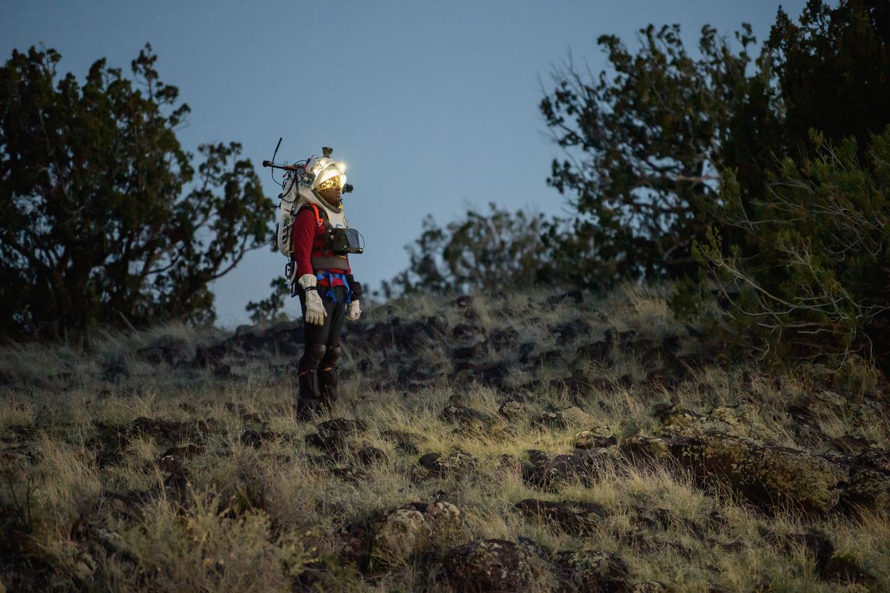
NASA astronaut Andre Douglas views the lunar-like landscape at dusk while wearing the Joint AR (Joint Augmented Reality Visual Informatics System) display during an advanced technology run in the San Francisco Volcanic Field in Northern Arizona on May 21, 2024. The suit display features include navigation, photo capture, graphical format of consumables, procedure viewing, mission control updates, and other augmented reality cues and graphics. The team successfully tested navigation displays using data from four different data streams: GPS (Global Positioning System)/IMU (Inertial Measurement Unit), camera/IMU, LiDAR (Light Detection and Ranging), and static maps. Technology like this may be used for future Artemis missions to augment mission control communication and help guide crew back to the lunar lander. Credit: NASA/Josh Valcarcel
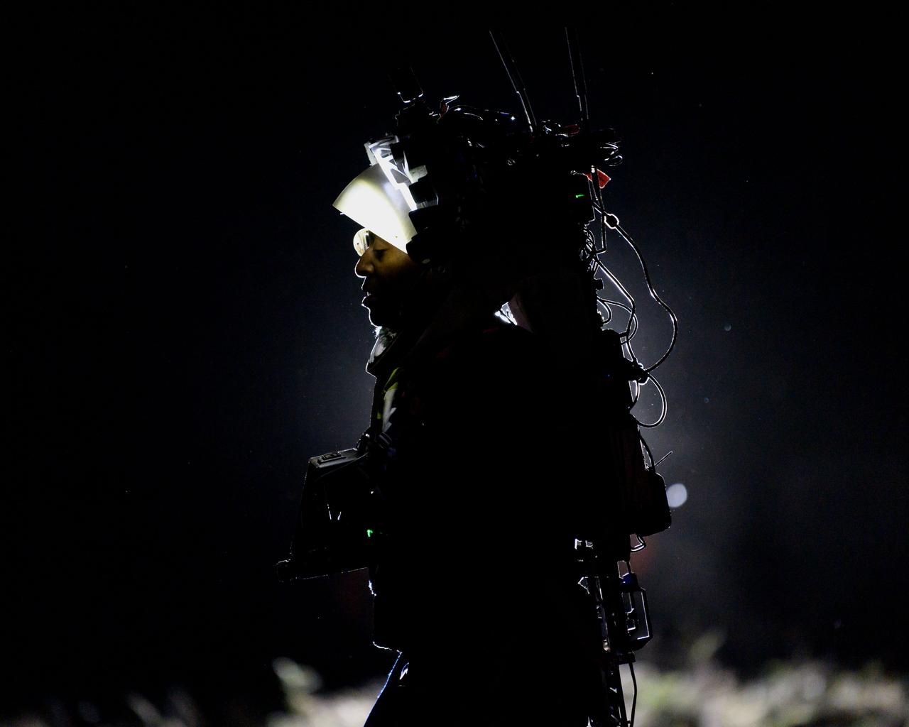
NASA astronaut Andre Douglas wears the Joint AR (Joint Augmented Reality Visual Informatics System) display during a nighttime advanced technology run in the San Francisco Volcanic Field in Northern Arizona on May 21, 2024. The suit display features include navigation, photo capture, graphical format of consumables, procedure viewing, mission control updates, and other augmented reality cues and graphics. The team successfully tested navigation displays using data from four different data streams: GPS (Global Positioning System)/IMU (Inertial Measurement Unit), camera/IMU, LiDAR (Light Detection and Ranging), and static maps. Technology like this may be used for future Artemis missions to augment mission control communication and help guide crew back to the lunar lander. Credit: NASA/Josh Valcarcel
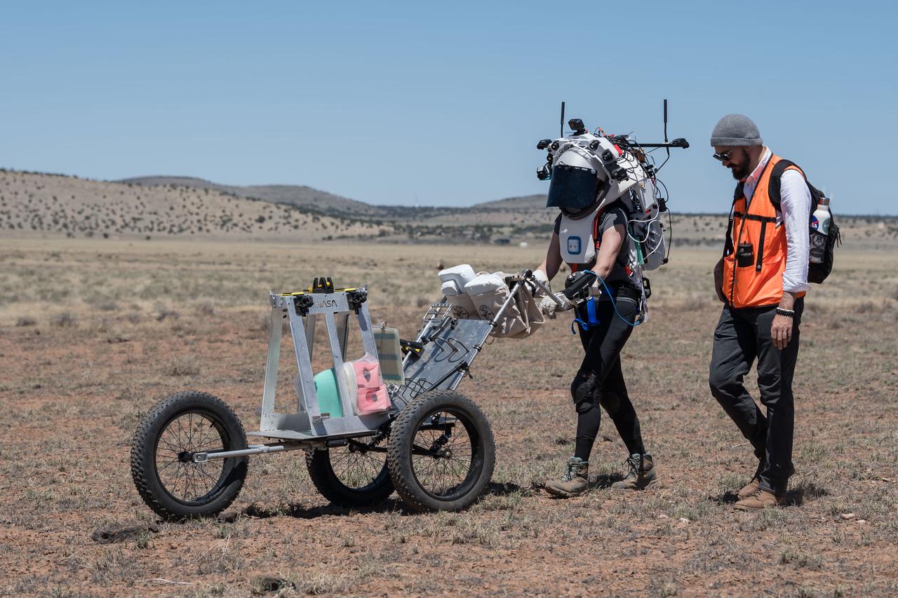
NASA astronaut Kate Rubins pushes a cart through the lunar-like landscape while wearing the Joint AR (Joint Augmented Reality Visual Informatics System) display during an advanced technology run in the San Francisco Volcanic Field in Northern Arizona on May 19, 2024. The suit display features include navigation, photo capture, graphical format of consumables, procedure viewing, mission control updates, and other augmented reality cues and graphics. The team successfully tested navigation displays using data from four different data streams: GPS (Global Positioning System)/IMU (Inertial Measurement Unit), camera/IMU, LiDAR (Light Detection and Ranging), and static maps. Technology like this may be used for future Artemis missions to augment mission control communication and help guide crew back to the lunar lander. Credit: NASA/Josh Valcarcel
NASA astronauts Andre Douglas and Kate Rubins during a nighttime advanced technology run in the San Francisco Volcanic Field in Northern Arizona on May 21, 2024. Douglas is wearing the Joint AR (Joint Augmented Reality Visual Informatics System) display. The suit display features include navigation, photo capture, graphical format of consumables, procedure viewing, mission control updates, and other augmented reality cues and graphics. The team successfully tested navigation displays using data from four different data streams: GPS (Global Positioning System)/IMU (Inertial Measurement Unit), camera/IMU, LiDAR (Light Detection and Ranging), and static maps. Technology like this may be used for future Artemis missions to augment mission control communication and help guide crew back to the lunar lander. Credit: NASA/Josh Valcarcel
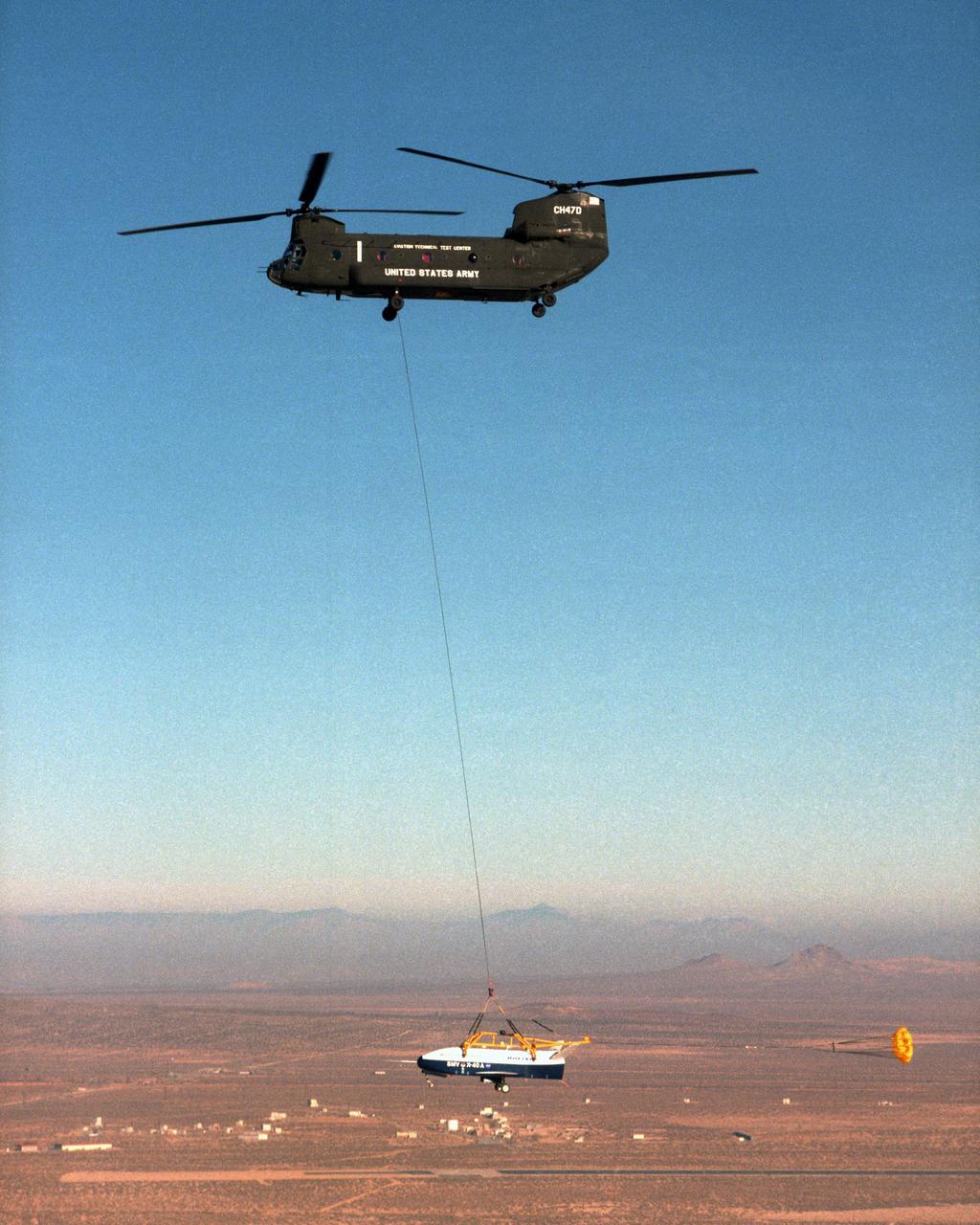
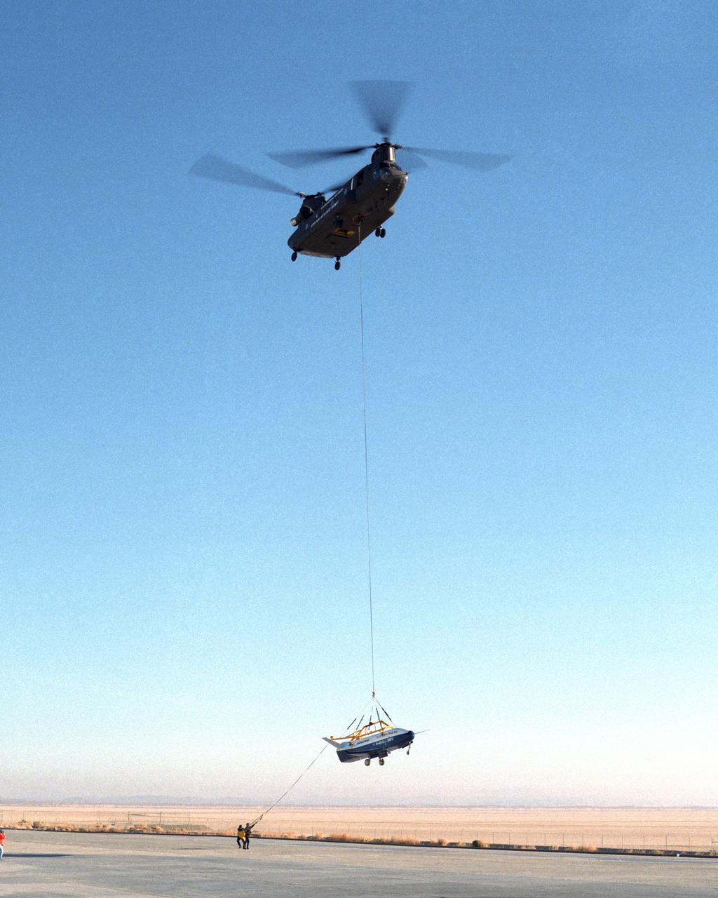
With a small stabilization parachute trailing behind, the X-40 sub-scale technology demonstrator is suspended under a U.S. Army CH-47 Chinook cargo helicopter during a captive-carry test flight at NASA's Dryden Flight Research Center, Edwards, California. The captive carry flights are designed to verify the X-40's navigation and control systems, rigging angles for its sling, and stability and control of the helicopter while carrying the X-40 on a tether. Following a series of captive-carry flights, the X-40 made free flights from a launch altitude of about 15,000 feet above ground, gliding to a fully autonomous landing. The X-40 is an unpowered 82 percent scale version of the X-37, a Boeing-developed spaceplane designed to demonstrate various advanced technologies for development of future lower-cost access to space vehicles.
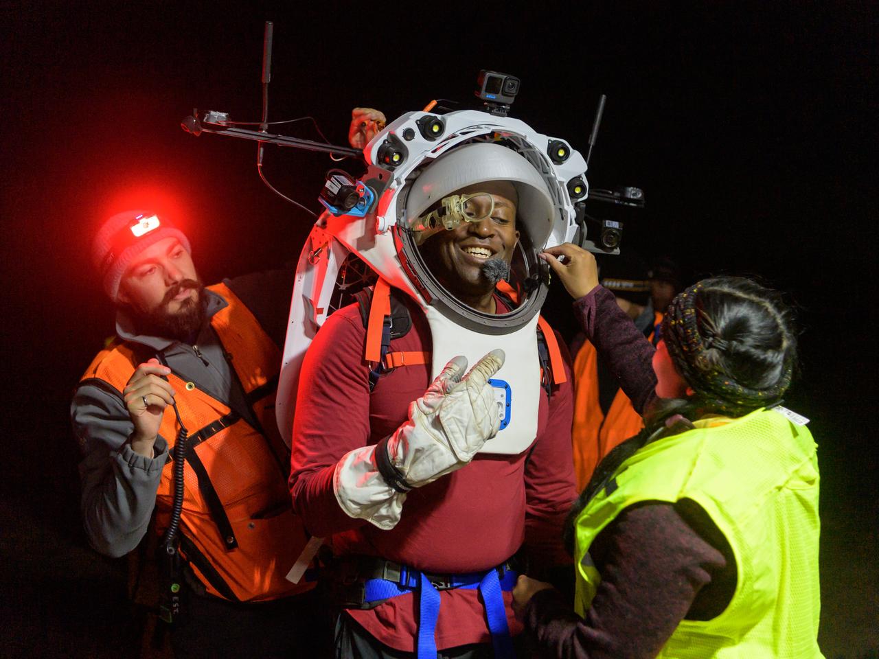
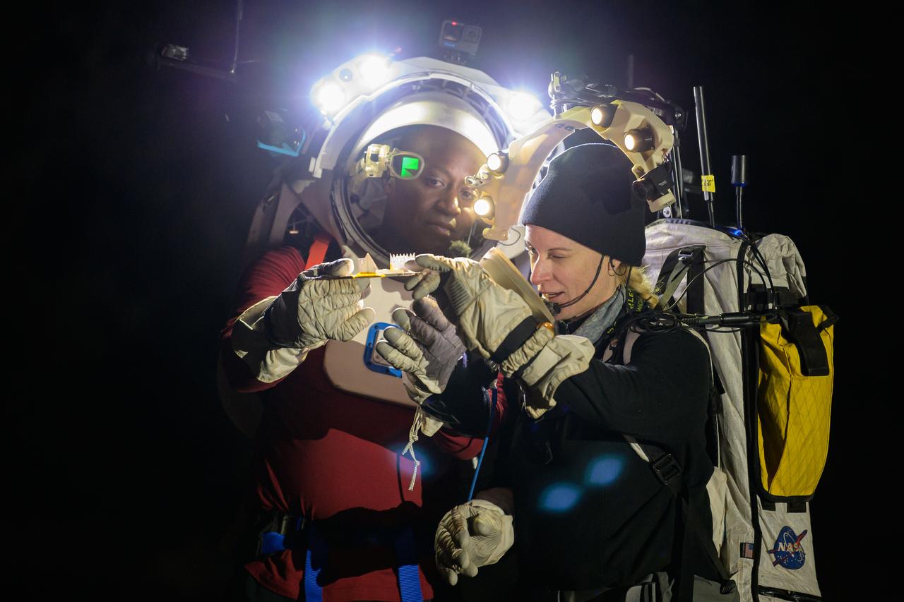
Engineers help NASA astronaut Andre Douglas adjust the Joint AR (Joint Augmented Reality Visual Informatics System) display he’s wearing during a nighttime advanced technology run in the San Francisco Volcanic Field in Northern Arizona on May 21, 2024. The suit display features include navigation, photo capture, graphical format of consumables, procedure viewing, mission control updates, and other augmented reality cues and graphics. The team successfully tested navigation displays using data from four different data streams: GPS (Global Positioning System)/IMU (Inertial Measurement Unit), camera/IMU, LiDAR (Light Detection and Ranging), and static maps. Technology like this may be used for future Artemis missions to augment mission control communication and help guide crew back to the lunar lander. Credit: NASA/Josh Valcarcel
The X-40 sub-scale technology demonstrator is suspended under a U.S. Army CH-47 Chinook cargo helicopter during a captive-carry test flight at NASA's Dryden Flight Research Center, Edwards, California. The captive carry flights are designed to verify the X-40's navigation and control systems, rigging angles for its sling, and stability and control of the helicopter while carrying the X-40 on a tether. Following a series of captive-carry flights, the X-40 made free flights from a launch altitude of about 15,000 feet above ground, gliding to a fully autonomous landing. The X-40 is an unpowered 82 percent scale version of the X-37, a Boeing-developed spaceplane designed to demonstrate various advanced technologies for development of future lower-cost access to space vehicles.
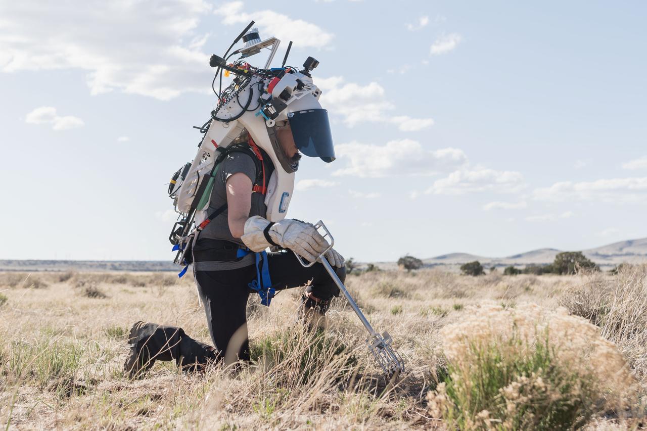
NASA astronaut Kate Rubins uses tongs to collect geologic samples while wearing the Joint AR (Joint Augmented Reality Visual Informatics System) display during an advanced technology run in the San Francisco Volcanic Field in Northern Arizona on May 21, 2024. The suit display features include navigation, photo capture, graphical format of consumables, procedure viewing, mission control updates, and other augmented reality cues and graphics. The team successfully tested navigation displays using data from four different data streams: GPS (Global Positioning System)/IMU (Inertial Measurement Unit), camera/IMU, LiDAR (Light Detection and Ranging), and static maps. Technology like this may be used for future Artemis missions to augment mission control communication and help guide crew back to the lunar lander. Credit: NASA/Josh Valcarcel
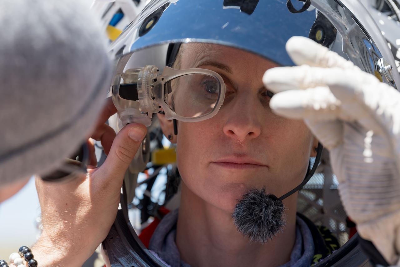
An engineer helps NASA astronaut Kate Rubins adjust the lens on the Joint AR (Joint Augmented Reality Visual Informatics System) display she’s wearing during an advanced technology run in the San Francisco Volcanic Field in Northern Arizona on May 19, 2024. The suit display features include navigation, photo capture, graphical format of consumables, procedure viewing, mission control updates, and other augmented reality cues and graphics. The team successfully tested navigation displays using data from four different data streams: GPS (Global Positioning System)/IMU (Inertial Measurement Unit), camera/IMU, LiDAR (Light Detection and Ranging), and static maps. Technology like this may be used for future Artemis missions to augment mission control communication and help guide crew back to the lunar lander. Credit: NASA/Josh Valcarcel
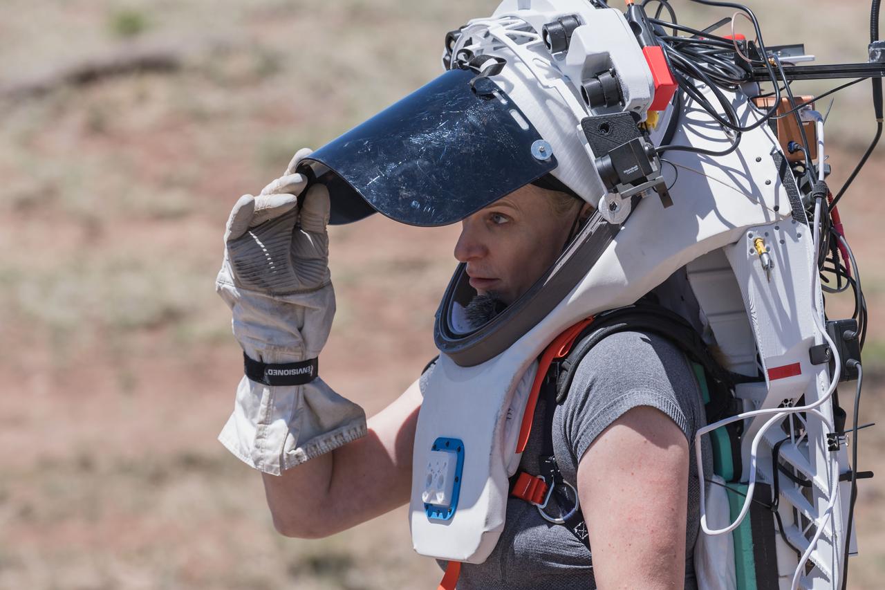
NASA astronaut Kate Rubins opens the sun visor on the Joint AR (Joint Augmented Reality Visual Informatics System) display she’s wearing during an advanced technology run in the San Francisco Volcanic Field in Northern Arizona on May 19, 2024. The suit display features include navigation, photo capture, graphical format of consumables, procedure viewing, mission control updates, and other augmented reality cues and graphics. The team successfully tested navigation displays using data from four different data streams: GPS (Global Positioning System)/IMU (Inertial Measurement Unit), camera/IMU, LiDAR (Light Detection and Ranging), and static maps. Technology like this may be used for future Artemis missions to augment mission control communication and help guide crew back to the lunar lander. Credit: NASA/Josh Valcarcel
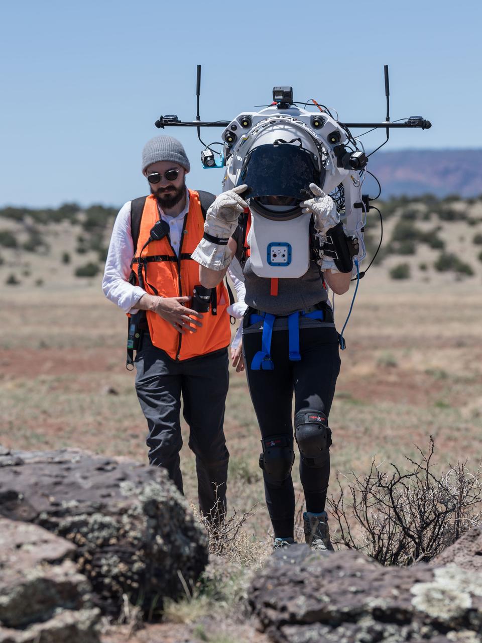
NASA astronaut Kate Rubins walks through the lunar-like landscape wearing the Joint AR (Joint Augmented Reality Visual Informatics System) display during an advanced technology run in the San Francisco Volcanic Field in Northern Arizona on May 19, 2024. The suit display features include navigation, photo capture, graphical format of consumables, procedure viewing, mission control updates, and other augmented reality cues and graphics. The team successfully tested navigation displays using data from four different data streams: GPS (Global Positioning System)/IMU (Inertial Measurement Unit), camera/IMU, LiDAR (Light Detection and Ranging), and static maps. Technology like this may be used for future Artemis missions to augment mission control communication and help guide crew back to the lunar lander. Credit: NASA/Josh Valcarcel

NASA's F/A-18 Hornet is seen here in a banked turn over Rogers Dry Lake in the Mojave desert on an early research flight. It was flown by NASA's Dryden Flight Research Center, Edwards, California, in a multi-year, joint NASA/DOD/industry program, the former Navy fighter was modified into a unique Systems Research Aircraft (SRA) to investigate a host of new technologies in the areas of flight controls, airdata sensing and advanced computing. One of the more than 20 experiments tested aboard the SRA F-18 was an advanced air data sensing system which used a group of pressure taps flush-mounted on the forward fuselage to measure both altitude and wind speed and direction--critical data for flight control and research investigations. The Real-Time Flush Air Data Sensing system concept was evaluated for possible use on the X-33 and X-34 resuable space-launch vehicles. The primary goal of the SRA program was to validate through flight research cutting-edge technologies which could benefit future aircraft and spacecraft by improving efficiency and performance, reducing weight and complexity, with a resultant reduction on development and operational costs.
Ground crewmen help guide the alignment of the X-40 technology demonstrator as the experimental craft is gently lowered to the ground by a U.S. Army CH-47 Chinook cargo helicopter following a captive-carry test flight at NASA's Dryden Flight Research Center, Edwards, California. The X-40 is an unpowered 82 percent scale version of the X-37, a Boeing-developed spaceplane designed to demonstrate various advanced technologies for development of future lower-cost access to space vehicles. The X-37 will be carried into space aboard a space shuttle and then released to perform various maneuvers and a controlled re-entry through the Earth's atmosphere to an airplane-style landing on a runway, controlled entirely by pre-programmed computer software. Following a series of captive-carry flights, the X-40 made several free flights from a launch altitude of about 15,000 feet above ground, gliding to a fully autonomous landing. The captive carry flights helped verify the X-40's navigation and control systems, rigging angles for its sling, and stability and control of the helicopter while carrying the X-40 on a tether.
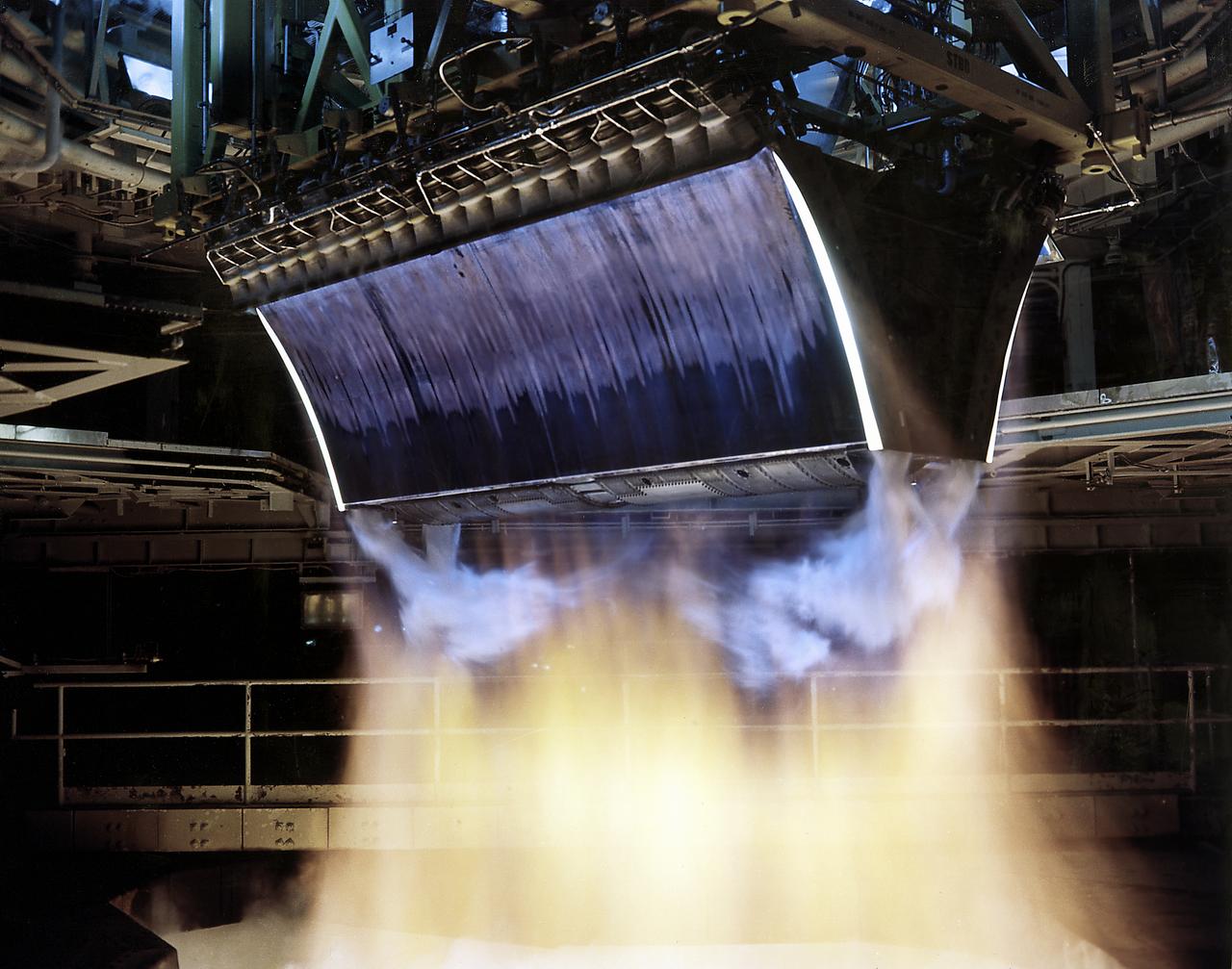
The test of twin Linear Aerospike XRS-2200 engines, originally built for the X-33 program, was performed on August 6, 2001 at NASA's Sternis Space Center, Mississippi. The engines were fired for the planned 90 seconds and reached a planned maximum power of 85 percent. NASA's Second Generation Reusable Launch Vehicle Program , also known as the Space Launch Initiative (SLI), is making advances in propulsion technology with this third and final successful engine hot fire, designed to test electro-mechanical actuators. Information learned from this hot fire test series about new electro-mechanical actuator technology, which controls the flow of propellants in rocket engines, could provide key advancements for the propulsion systems for future spacecraft. The Second Generation Reusable Launch Vehicle Program, led by NASA's Marshall Space Flight Center in Huntsville, Alabama, is a technology development program designed to increase safety and reliability while reducing costs for space travel. The X-33 program was cancelled in March 2001.

ISS022-E-011304 (15 Dec. 2009) --- NASA astronaut Jeffrey Williams, Expedition 22 commander, conducts a daily status check of the Advanced Plant Experiments on Orbit (APEX) experiment in the Kibo laboratory of the International Space Station. During each check, Williams looks for health and color of the plants, since the Cambium plants are removed from the Advanced Biological Research System (ABRS). When completed, the APEX-Cambium payload in conjunction with the NASA-sponsored Transgenic Arabidopsis Gene Expression System (TAGES) will determine the role of gravity in Cambium wood cell development and demonstrate non-destructive reporter gene technology and investigate spaceflight plant stress. APEX-Cambium provides NASA and the ISS community a permanent controlled environment capability to support growth of various organisms (i.e. whole plants).
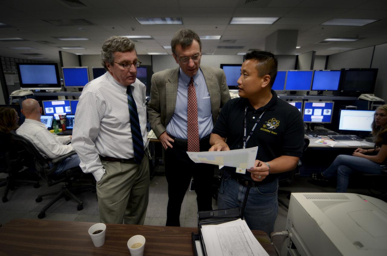
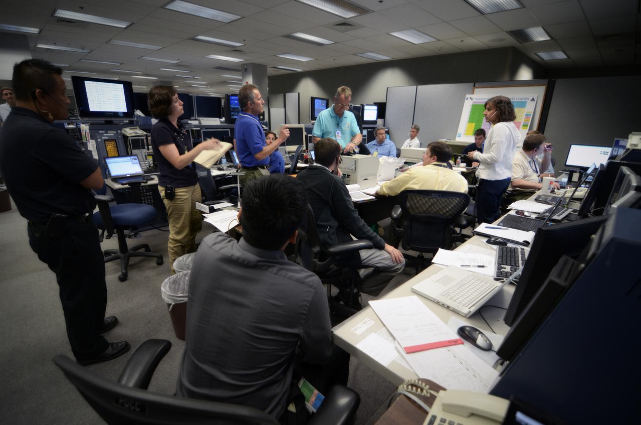
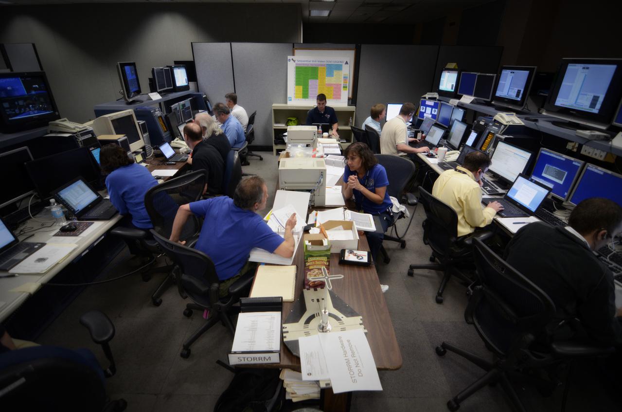
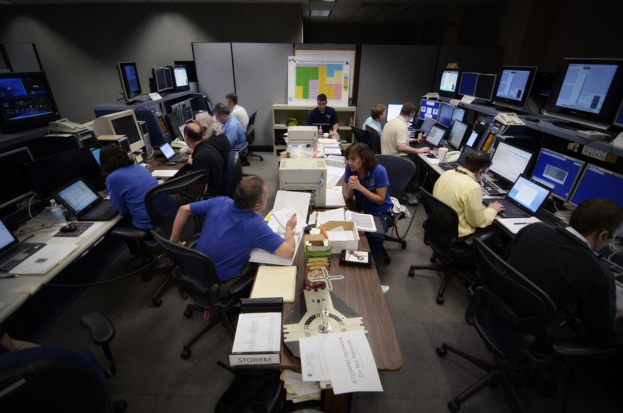
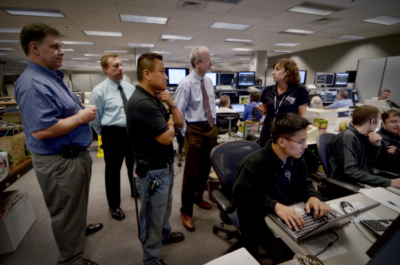
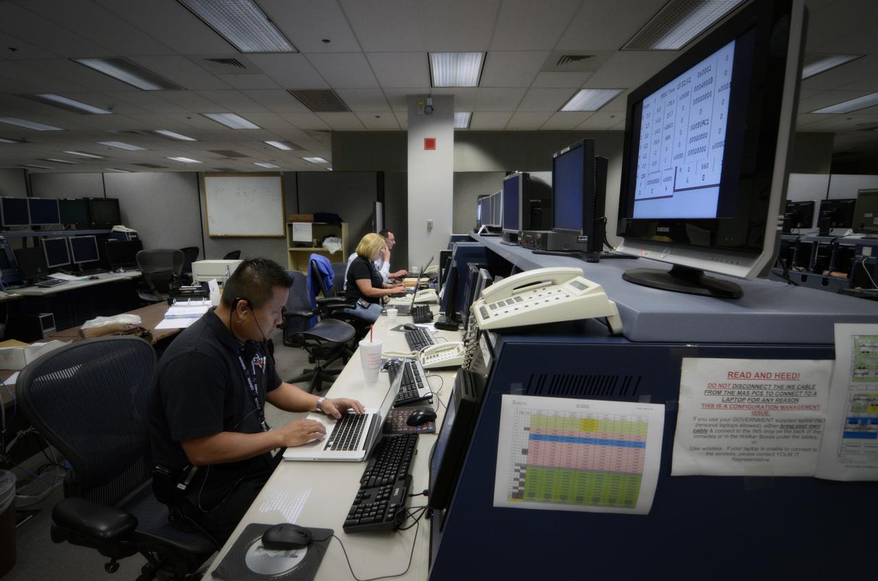
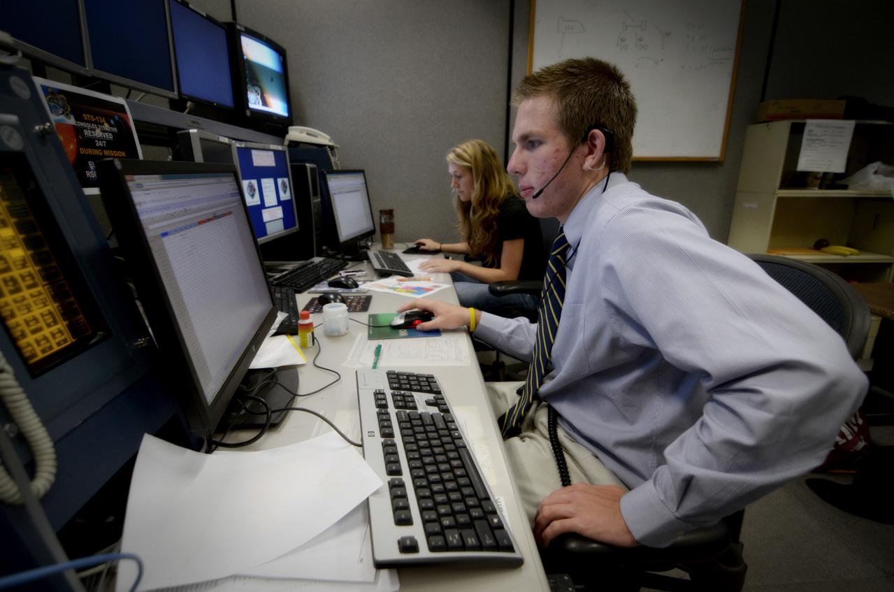
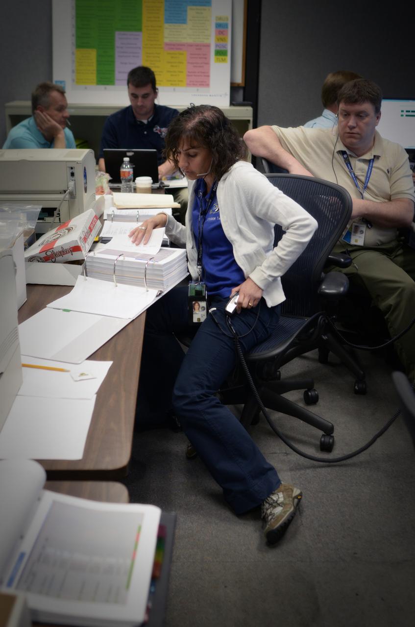
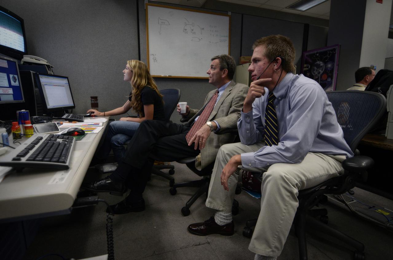
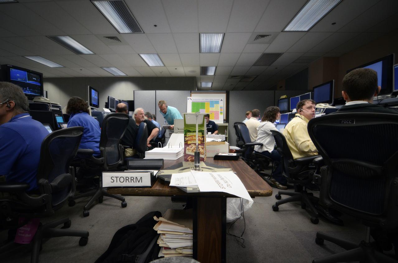
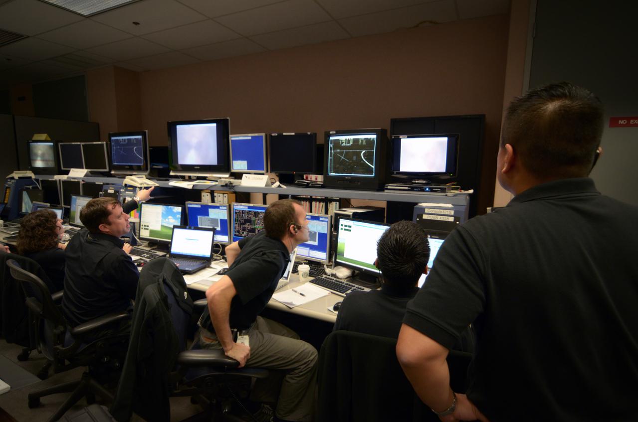
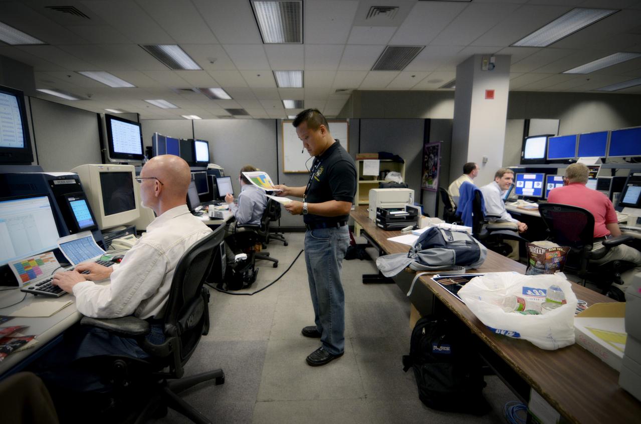
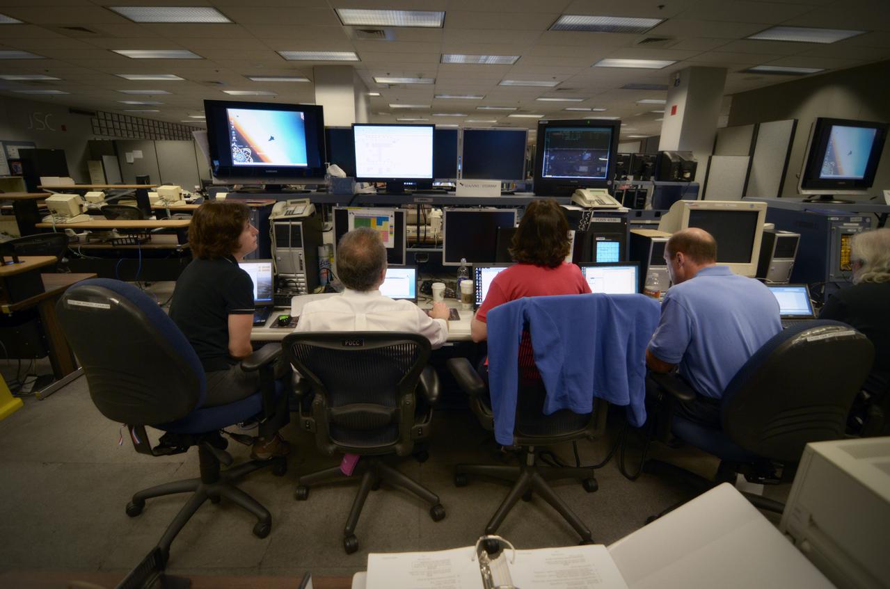
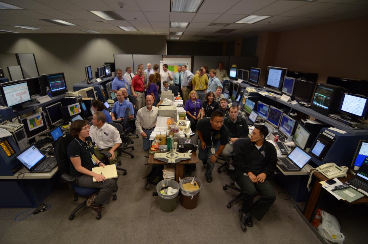
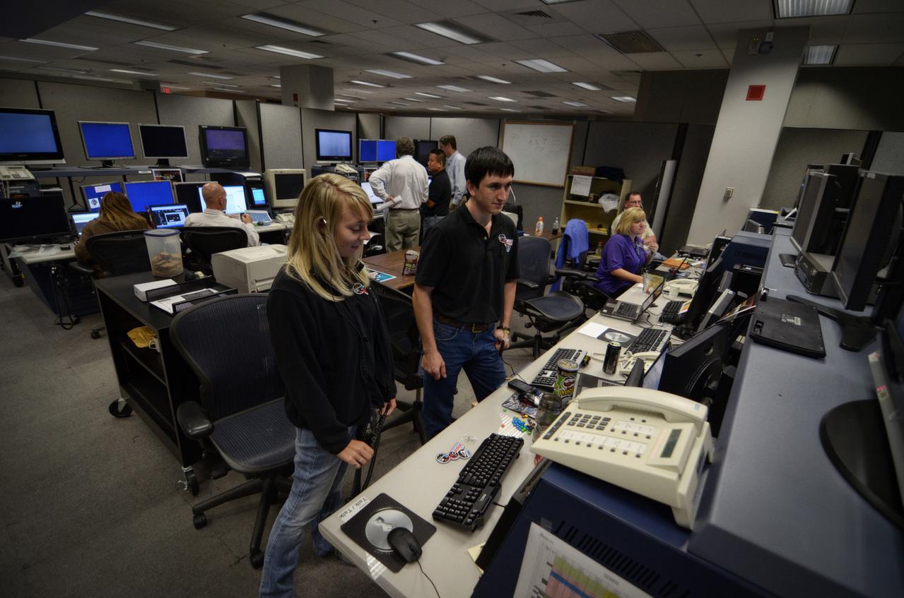
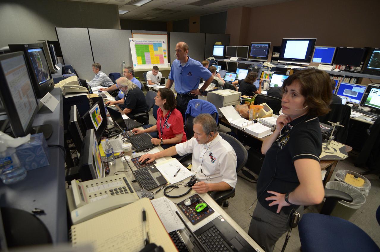
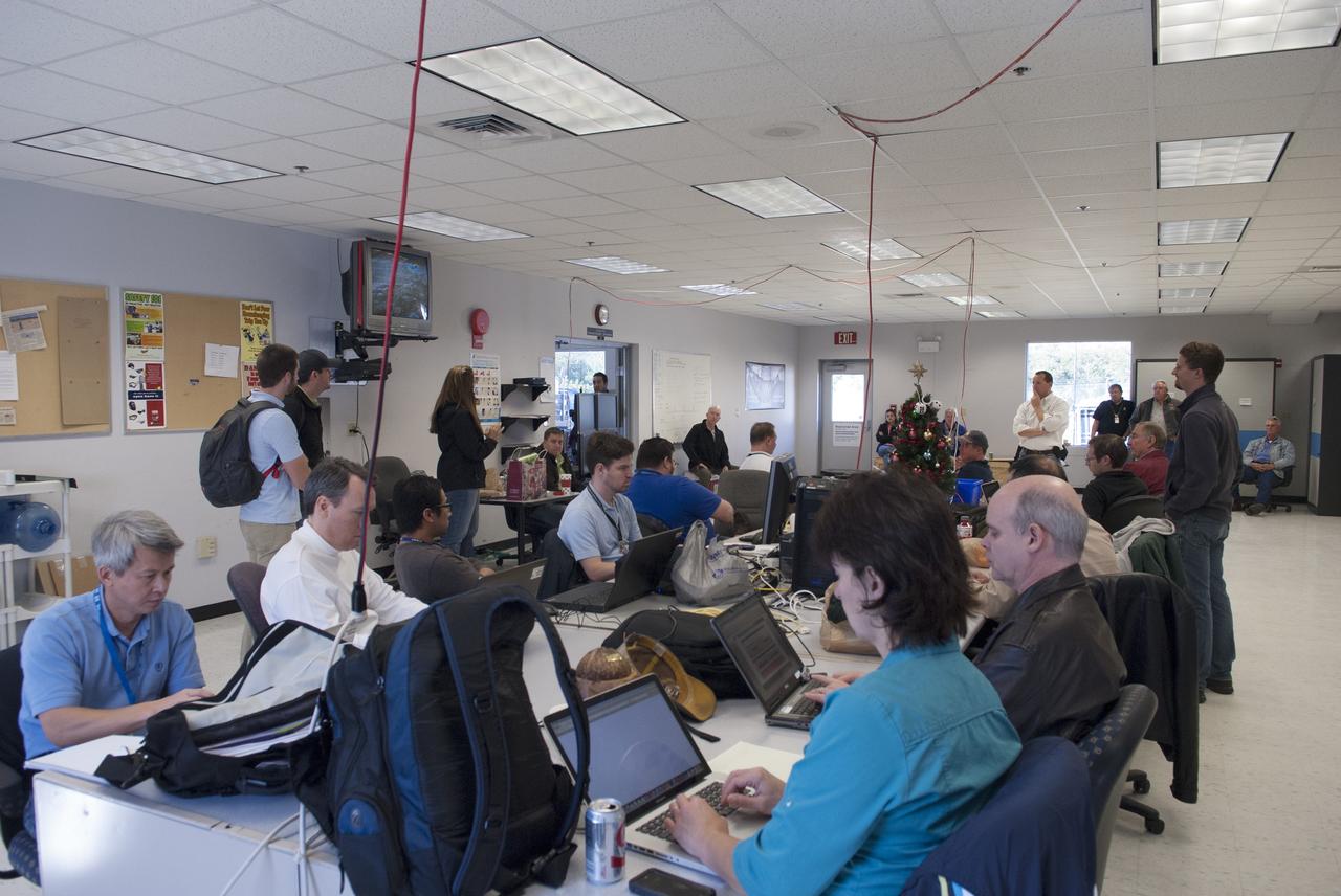
Teams conduct powerup and docking operations for the Sensor Test for Orion Relative Navigation Risk Mitigation (STORRM) in a payload support room at Johnson Space Center’s Mission Control Center in Houston on May 18, 2011. STORRM was successfully demonstrated on Space Shuttle Endeavour’s STS-134 mission to the International Space Station. The goal of STORRM was to validate a new relative navigation sensor based on advanced laser and detector technology that will make docking and undocking spacecraft easier and safer. It also tested the hardware in the same environment that the sensors would experience on the first Orion rendezvous to another vehicle.
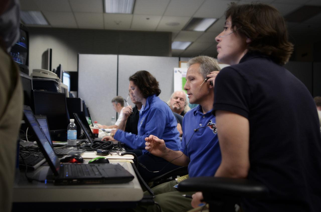
Teams conduct powerup and docking operations for the Sensor Test for Orion Relative Navigation Risk Mitigation (STORRM) in a payload support room at Johnson Space Center’s Mission Control Center in Houston on May 17, 2011. STORRM was successfully demonstrated on Space Shuttle Endeavour’s STS-134 mission to the International Space Station. The goal of STORRM was to validate a new relative navigation sensor based on advanced laser and detector technology that will make docking and undocking spacecraft easier and safer. It also tested the hardware in the same environment that the sensors would experience on the first Orion rendezvous to another vehicle.

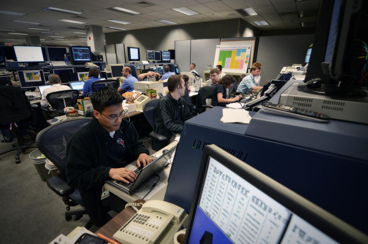
Teams conduct powerup and docking operations for the Sensor Test for Orion Relative Navigation Risk Mitigation (STORRM) in a payload support room at Johnson Space Center’s Mission Control Center in Houston on May 18, 2011. STORRM was successfully demonstrated on Space Shuttle Endeavour’s STS-134 mission to the International Space Station. The goal of STORRM was to validate a new relative navigation sensor based on advanced laser and detector technology that will make docking and undocking spacecraft easier and safer. It also tested the hardware in the same environment that the sensors would experience on the first Orion rendezvous to another vehicle.

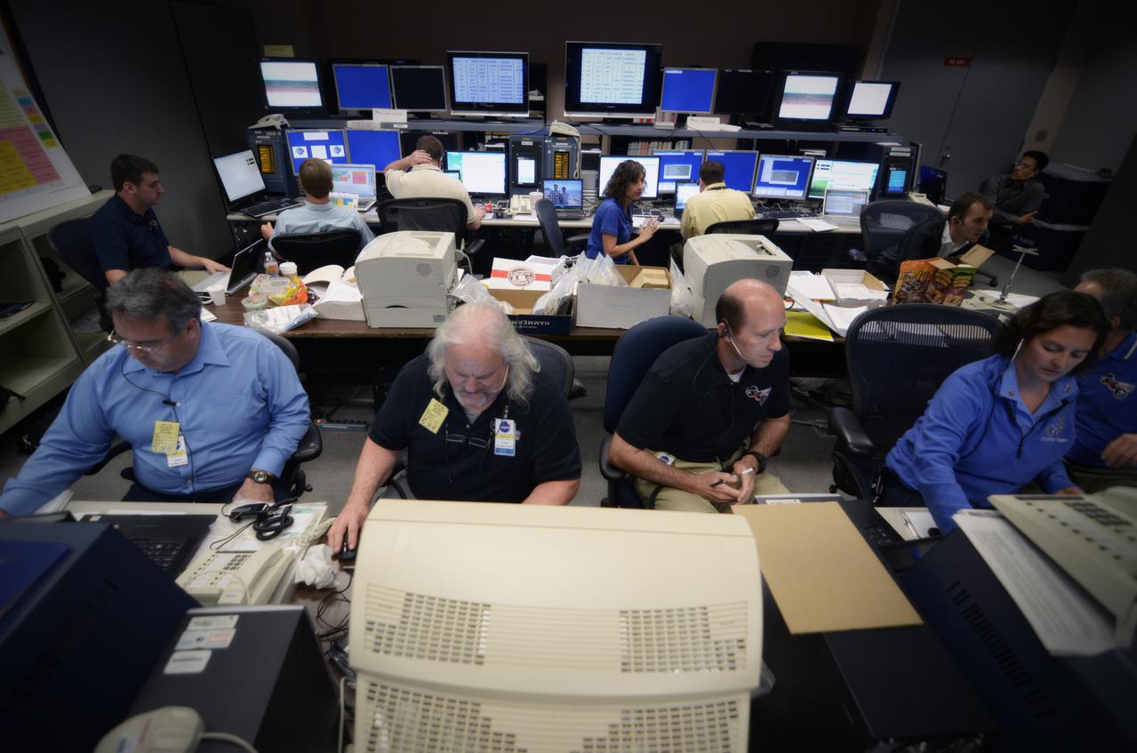
Teams conduct powerup and docking operations for the Sensor Test for Orion Relative Navigation Risk Mitigation (STORRM) in a payload support room at Johnson Space Center’s Mission Control Center in Houston on May 17, 2011. STORRM was successfully demonstrated on Space Shuttle Endeavour’s STS-134 mission to the International Space Station. The goal of STORRM was to validate a new relative navigation sensor based on advanced laser and detector technology that will make docking and undocking spacecraft easier and safer. It also tested the hardware in the same environment that the sensors would experience on the first Orion rendezvous to another vehicle.

Teams conduct powerup and docking operations for the Sensor Test for Orion Relative Navigation Risk Mitigation (STORRM) in a payload support room at Johnson Space Center’s Mission Control Center in Houston on May 18, 2011. STORMM was successfully demonstrated on Space Shuttle Endeavour’s STS-134 mission to the International Space Station..The goal of STORRM was to validate a new relative navigation sensor based on advanced laser and detector technology that will make docking and undocking spacecraft easier and safer. It also tested the hardware in the same environment that the sensors would experience on the first Orion rendezvous to another vehicle. Part of Batch image transfer from Flickr.

Teams conduct powerup and docking operations for the Sensor Test for Orion Relative Navigation Risk Mitigation (STORRM) in a payload support room at Johnson Space Center’s Mission Control Center in Houston on May 18, 2011. STORRM was successfully demonstrated on Space Shuttle Endeavour’s STS-134 mission to the International Space Station. The goal of STORRM was to validate a new relative navigation sensor based on advanced laser and detector technology that will make docking and undocking spacecraft easier and safer. It also tested the hardware in the same environment that the sensors would experience on the first Orion rendezvous to another vehicle.

Teams conduct powerup and docking operations for the Sensor Test for Orion Relative Navigation Risk Mitigation (STORRM) in a payload support room at Johnson Space Center’s Mission Control Center in Houston on May 17, 2011. STORRM was successfully demonstrated on Space Shuttle Endeavour’s STS-134 mission to the International Space Station. The goal of STORRM was to validate a new relative navigation sensor based on advanced laser and detector technology that will make docking and undocking spacecraft easier and safer. It also tested the hardware in the same environment that the sensors would experience on the first Orion rendezvous to another vehicle.
Teams conduct powerup and docking operations for the Sensor Test for Orion Relative Navigation Risk Mitigation (STORRM) in a payload support room at Johnson Space Center’s Mission Control Center in Houston on May 17, 2011. STORRM was successfully demonstrated on Space Shuttle Endeavour’s STS-134 mission to the International Space Station. The goal of STORRM was to validate a new relative navigation sensor based on advanced laser and detector technology that will make docking and undocking spacecraft easier and safer. It also tested the hardware in the same environment that the sensors would experience on the first Orion rendezvous to another vehicle.
Teams conduct powerup and docking operations for the Sensor Test for Orion Relative Navigation Risk Mitigation (STORRM) in a payload support room at Johnson Space Center’s Mission Control Center in Houston on May 18, 2011. STORMM was successfully demonstrated on Space Shuttle Endeavour’s STS-134 mission to the International Space Station..The goal of STORRM was to validate a new relative navigation sensor based on advanced laser and detector technology that will make docking and undocking spacecraft easier and safer. It also tested the hardware in the same environment that the sensors would experience on the first Orion rendezvous to another vehicle. Part of Batch image transfer from Flickr.
Teams conduct powerup and docking operations for the Sensor Test for Orion Relative Navigation Risk Mitigation (STORRM) in a payload support room at Johnson Space Center’s Mission Control Center in Houston on May 18, 2011. STORMM was successfully demonstrated on Space Shuttle Endeavour’s STS-134 mission to the International Space Station..The goal of STORRM was to validate a new relative navigation sensor based on advanced laser and detector technology that will make docking and undocking spacecraft easier and safer. It also tested the hardware in the same environment that the sensors would experience on the first Orion rendezvous to another vehicle. Part of Batch image transfer from Flickr.
Teams conduct powerup and docking operations for the Sensor Test for Orion Relative Navigation Risk Mitigation (STORRM) in a payload support room at Johnson Space Center’s Mission Control Center in Houston on May 18, 2011. STORMM was successfully demonstrated on Space Shuttle Endeavour’s STS-134 mission to the International Space Station..The goal of STORRM was to validate a new relative navigation sensor based on advanced laser and detector technology that will make docking and undocking spacecraft easier and safer. It also tested the hardware in the same environment that the sensors would experience on the first Orion rendezvous to another vehicle. Part of Batch image transfer from Flickr.
Teams conduct powerup and docking operations for the Sensor Test for Orion Relative Navigation Risk Mitigation (STORRM) in a payload support room at Johnson Space Center’s Mission Control Center in Houston on May 17, 2011. STORRM was successfully demonstrated on Space Shuttle Endeavour’s STS-134 mission to the International Space Station. The goal of STORRM was to validate a new relative navigation sensor based on advanced laser and detector technology that will make docking and undocking spacecraft easier and safer. It also tested the hardware in the same environment that the sensors would experience on the first Orion rendezvous to another vehicle.
Teams conduct powerup and docking operations for the Sensor Test for Orion Relative Navigation Risk Mitigation (STORRM) in a payload support room at Johnson Space Center’s Mission Control Center in Houston on May 18, 2011. STORRM was successfully demonstrated on Space Shuttle Endeavour’s STS-134 mission to the International Space Station. The goal of STORRM was to validate a new relative navigation sensor based on advanced laser and detector technology that will make docking and undocking spacecraft easier and safer. It also tested the hardware in the same environment that the sensors would experience on the first Orion rendezvous to another vehicle.

Teams conduct powerup and docking operations for the Sensor Test for Orion Relative Navigation Risk Mitigation (STORRM) in a payload support room at Johnson Space Center’s Mission Control Center in Houston on May 18, 2011. STORMM was successfully demonstrated on Space Shuttle Endeavour’s STS-134 mission to the International Space Station..The goal of STORRM was to validate a new relative navigation sensor based on advanced laser and detector technology that will make docking and undocking spacecraft easier and safer. It also tested the hardware in the same environment that the sensors would experience on the first Orion rendezvous to another vehicle. Part of Batch image transfer from Flickr.
Teams conduct powerup and docking operations for the Sensor Test for Orion Relative Navigation Risk Mitigation (STORRM) in a payload support room at Johnson Space Center’s Mission Control Center in Houston on May 18, 2011. STORMM was successfully demonstrated on Space Shuttle Endeavour’s STS-134 mission to the International Space Station..The goal of STORRM was to validate a new relative navigation sensor based on advanced laser and detector technology that will make docking and undocking spacecraft easier and safer. It also tested the hardware in the same environment that the sensors would experience on the first Orion rendezvous to another vehicle. Part of Batch image transfer from Flickr.
Teams conduct powerup and docking operations for the Sensor Test for Orion Relative Navigation Risk Mitigation (STORRM) in a payload support room at Johnson Space Center’s Mission Control Center in Houston on May 18, 2011. STORMM was successfully demonstrated on Space Shuttle Endeavour’s STS-134 mission to the International Space Station..The goal of STORRM was to validate a new relative navigation sensor based on advanced laser and detector technology that will make docking and undocking spacecraft easier and safer. It also tested the hardware in the same environment that the sensors would experience on the first Orion rendezvous to another vehicle. Part of Batch image transfer from Flickr.

Teams conduct powerup and docking operations for the Sensor Test for Orion Relative Navigation Risk Mitigation (STORRM) in a payload support room at Johnson Space Center’s Mission Control Center in Houston on May 18, 2011. STORMM was successfully demonstrated on Space Shuttle Endeavour’s STS-134 mission to the International Space Station..The goal of STORRM was to validate a new relative navigation sensor based on advanced laser and detector technology that will make docking and undocking spacecraft easier and safer. It also tested the hardware in the same environment that the sensors would experience on the first Orion rendezvous to another vehicle. Part of Batch image transfer from Flickr.

Teams conduct powerup and docking operations for the Sensor Test for Orion Relative Navigation Risk Mitigation (STORRM) in a payload support room at Johnson Space Center’s Mission Control Center in Houston on May 18, 2011. STORRM was successfully demonstrated on Space Shuttle Endeavour’s STS-134 mission to the International Space Station. The goal of STORRM was to validate a new relative navigation sensor based on advanced laser and detector technology that will make docking and undocking spacecraft easier and safer. It also tested the hardware in the same environment that the sensors would experience on the first Orion rendezvous to another vehicle.
Teams conduct powerup and docking operations for the Sensor Test for Orion Relative Navigation Risk Mitigation (STORRM) in a payload support room at Johnson Space Center’s Mission Control Center in Houston on May 18, 2011. STORMM was successfully demonstrated on Space Shuttle Endeavour’s STS-134 mission to the International Space Station..The goal of STORRM was to validate a new relative navigation sensor based on advanced laser and detector technology that will make docking and undocking spacecraft easier and safer. It also tested the hardware in the same environment that the sensors would experience on the first Orion rendezvous to another vehicle. Part of Batch image transfer from Flickr.
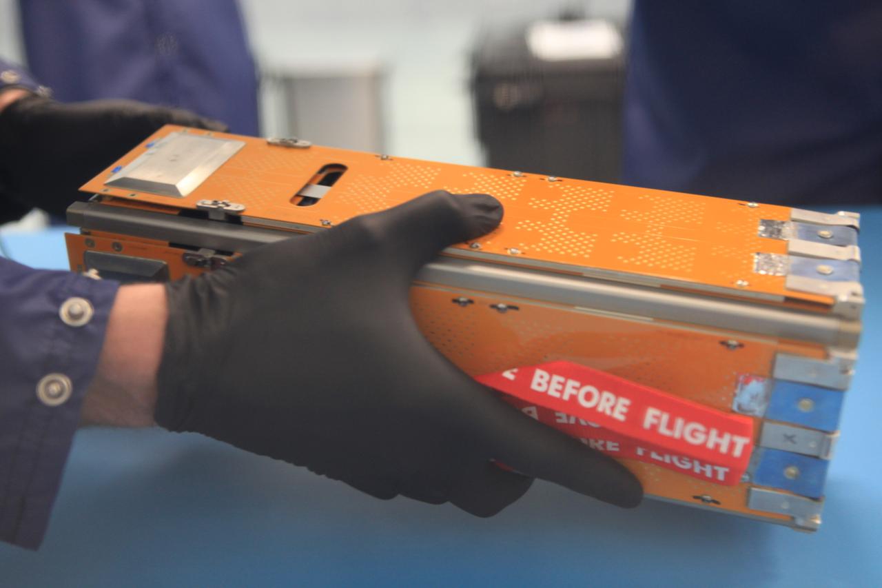
The Advanced Electrical Bus (ALBus) mission is a technology demonstration of resettable Shape Memory Alloy (SMA) mechanisms for deployable solar arrays and a pathfinder for high power density CubeSats. The mission has two primary objectives. The first is to demonstrate the functionality of the novel SMA activated solar array mechanisms in the on-orbit environment. The second objective is to assess the system level ability to charge a high capacity battery, distribute 100 W of electrical power and thermally control the 3-U CubeSat system. Performance from the mission will be used to mature the SMA mechanism designs for CubeSat applications and plan for future high power density CubeSat missions.
Teams conduct powerup and docking operations for the Sensor Test for Orion Relative Navigation Risk Mitigation (STORRM) in a payload support room at Johnson Space Center’s Mission Control Center in Houston on May 18, 2011. STORRM was successfully demonstrated on Space Shuttle Endeavour’s STS-134 mission to the International Space Station. The goal of STORRM was to validate a new relative navigation sensor based on advanced laser and detector technology that will make docking and undocking spacecraft easier and safer. It also tested the hardware in the same environment that the sensors would experience on the first Orion rendezvous to another vehicle.

Teams conduct powerup and docking operations for the Sensor Test for Orion Relative Navigation Risk Mitigation (STORRM) in a payload support room at Johnson Space Center’s Mission Control Center in Houston on May 18, 2011. STORMM was successfully demonstrated on Space Shuttle Endeavour’s STS-134 mission to the International Space Station..The goal of STORRM was to validate a new relative navigation sensor based on advanced laser and detector technology that will make docking and undocking spacecraft easier and safer. It also tested the hardware in the same environment that the sensors would experience on the first Orion rendezvous to another vehicle. Part of Batch image transfer from Flickr.
Teams conduct powerup and docking operations for the Sensor Test for Orion Relative Navigation Risk Mitigation (STORRM) in a payload support room at Johnson Space Center’s Mission Control Center in Houston on May 18, 2011. STORMM was successfully demonstrated on Space Shuttle Endeavour’s STS-134 mission to the International Space Station..The goal of STORRM was to validate a new relative navigation sensor based on advanced laser and detector technology that will make docking and undocking spacecraft easier and safer. It also tested the hardware in the same environment that the sensors would experience on the first Orion rendezvous to another vehicle. Part of Batch image transfer from Flickr.
Teams conduct powerup and docking operations for the Sensor Test for Orion Relative Navigation Risk Mitigation (STORRM) in a payload support room at Johnson Space Center’s Mission Control Center in Houston on May 18, 2011. STORMM was successfully demonstrated on Space Shuttle Endeavour’s STS-134 mission to the International Space Station. The goal of STORRM was to validate a new relative navigation sensor based on advanced laser and detector technology that will make docking and undocking spacecraft easier and safer. It also tested the hardware in the same environment that the sensors would experience on the first Orion rendezvous to another vehicle.

Teams conduct powerup and docking operations for the Sensor Test for Orion Relative Navigation Risk Mitigation (STORRM) in a payload support room at Johnson Space Center’s Mission Control Center in Houston on May 18, 2011. STORRM was successfully demonstrated on Space Shuttle Endeavour’s STS-134 mission to the International Space Station. The goal of STORRM was to validate a new relative navigation sensor based on advanced laser and detector technology that will make docking and undocking spacecraft easier and safer. It also tested the hardware in the same environment that the sensors would experience on the first Orion rendezvous to another vehicle.

Teams conduct powerup and docking operations for the Sensor Test for Orion Relative Navigation Risk Mitigation (STORRM) in a payload support room at Johnson Space Center’s Mission Control Center in Houston on May 18, 2011. STORMM was successfully demonstrated on Space Shuttle Endeavour’s STS-134 mission to the International Space Station..The goal of STORRM was to validate a new relative navigation sensor based on advanced laser and detector technology that will make docking and undocking spacecraft easier and safer. It also tested the hardware in the same environment that the sensors would experience on the first Orion rendezvous to another vehicle. Part of Batch image transfer from Flickr.
Teams conduct powerup and docking operations for the Sensor Test for Orion Relative Navigation Risk Mitigation (STORRM) in a payload support room at Johnson Space Center’s Mission Control Center in Houston on May 18, 2011. STORMM was successfully demonstrated on Space Shuttle Endeavour’s STS-134 mission to the International Space Station..The goal of STORRM was to validate a new relative navigation sensor based on advanced laser and detector technology that will make docking and undocking spacecraft easier and safer. It also tested the hardware in the same environment that the sensors would experience on the first Orion rendezvous to another vehicle. Part of Batch image transfer from Flickr.

Teams conduct powerup and docking operations for the Sensor Test for Orion Relative Navigation Risk Mitigation (STORRM) in a payload support room at Johnson Space Center’s Mission Control Center in Houston on May 18, 2011. STORMM was successfully demonstrated on Space Shuttle Endeavour’s STS-134 mission to the International Space Station..The goal of STORRM was to validate a new relative navigation sensor based on advanced laser and detector technology that will make docking and undocking spacecraft easier and safer. It also tested the hardware in the same environment that the sensors would experience on the first Orion rendezvous to another vehicle. Part of Batch image transfer from Flickr.

Teams conduct powerup and docking operations for the Sensor Test for Orion Relative Navigation Risk Mitigation (STORRM) in a payload support room at Johnson Space Center’s Mission Control Center in Houston on May 17, 2011. STORRM was successfully demonstrated on Space Shuttle Endeavour’s STS-134 mission to the International Space Station. The goal of STORRM was to validate a new relative navigation sensor based on advanced laser and detector technology that will make docking and undocking spacecraft easier and safer. It also tested the hardware in the same environment that the sensors would experience on the first Orion rendezvous to another vehicle.
Teams conduct powerup and docking operations for the Sensor Test for Orion Relative Navigation Risk Mitigation (STORRM) in a payload support room at Johnson Space Center’s Mission Control Center in Houston on May 18, 2011. STORRM was successfully demonstrated on Space Shuttle Endeavour’s STS-134 mission to the International Space Station. The goal of STORRM was to validate a new relative navigation sensor based on advanced laser and detector technology that will make docking and undocking spacecraft easier and safer. It also tested the hardware in the same environment that the sensors would experience on the first Orion rendezvous to another vehicle.
Teams conduct powerup and docking operations for the Sensor Test for Orion Relative Navigation Risk Mitigation (STORRM) in a payload support room at Johnson Space Center’s Mission Control Center in Houston on May 18, 2011. STORRM was successfully demonstrated on Space Shuttle Endeavour’s STS-134 mission to the International Space Station. The goal of STORRM was to validate a new relative navigation sensor based on advanced laser and detector technology that will make docking and undocking spacecraft easier and safer. It also tested the hardware in the same environment that the sensors would experience on the first Orion rendezvous to another vehicle.

Teams conduct powerup and docking operations for the Sensor Test for Orion Relative Navigation Risk Mitigation (STORRM) in a payload support room at Johnson Space Center’s Mission Control Center in Houston on May 18, 2011. STORMM was successfully demonstrated on Space Shuttle Endeavour’s STS-134 mission to the International Space Station..The goal of STORRM was to validate a new relative navigation sensor based on advanced laser and detector technology that will make docking and undocking spacecraft easier and safer. It also tested the hardware in the same environment that the sensors would experience on the first Orion rendezvous to another vehicle. Part of Batch image transfer from Flickr.

Teams conduct powerup and docking operations for the Sensor Test for Orion Relative Navigation Risk Mitigation (STORRM) in a payload support room at Johnson Space Center’s Mission Control Center in Houston on May 18, 2011. STORMM was successfully demonstrated on Space Shuttle Endeavour’s STS-134 mission to the International Space Station..The goal of STORRM was to validate a new relative navigation sensor based on advanced laser and detector technology that will make docking and undocking spacecraft easier and safer. It also tested the hardware in the same environment that the sensors would experience on the first Orion rendezvous to another vehicle. Part of Batch image transfer from Flickr.

Teams conduct powerup and docking operations for the Sensor Test for Orion Relative Navigation Risk Mitigation (STORRM) in a payload support room at Johnson Space Center’s Mission Control Center in Houston on May 18, 2011. STORMM was successfully demonstrated on Space Shuttle Endeavour’s STS-134 mission to the International Space Station..The goal of STORRM was to validate a new relative navigation sensor based on advanced laser and detector technology that will make docking and undocking spacecraft easier and safer. It also tested the hardware in the same environment that the sensors would experience on the first Orion rendezvous to another vehicle. Part of Batch image transfer from Flickr.
Teams conduct powerup and docking operations for the Sensor Test for Orion Relative Navigation Risk Mitigation (STORRM) in a payload support room at Johnson Space Center’s Mission Control Center in Houston on May 18, 2011. STORRM was successfully demonstrated on Space Shuttle Endeavour’s STS-134 mission to the International Space Station. The goal of STORRM was to validate a new relative navigation sensor based on advanced laser and detector technology that will make docking and undocking spacecraft easier and safer. It also tested the hardware in the same environment that the sensors would experience on the first Orion rendezvous to another vehicle.
The Advanced Electrical Bus (ALBus) mission is a technology demonstration of resettable Shape Memory Alloy (SMA) mechanisms for deployable solar arrays and a pathfinder for high power density CubeSats. The mission has two primary objectives. The first is to demonstrate the functionality of the novel SMA activated solar array mechanisms in the on-orbit environment. The second objective is to assess the system level ability to charge a high capacity battery, distribute 100 W of electrical power and thermally control the 3-U CubeSat system. Performance from the mission will be used to mature the SMA mechanism designs for CubeSat applications and plan for future high power density CubeSat missions.
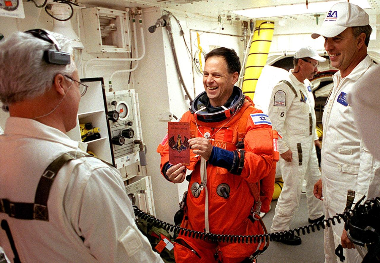
KENNEDY SPACE CENTER, FLA. -- STS-107 Payload Specialist Ilan Ramon, who represents the Israel Space Agency, chats with the Closeout Crew in the White Room before entering Columbia. The environmentally controlled chamber is mated to Space Shuttle Columbia for entry into the Shuttle. Ramon is the first Israeli astronaut to fly in the Shuttle. STS-107 is a mission devoted to research and will include more than 80 experiments that will study Earth and space science, advanced technology development, and astronaut health and safety. The payload on Space Shuttle Columbia includes FREESTAR (Fast Reaction Experiments Enabling Science, Technology, Applications and Research) and the SHI Research Double Module (SHI/RDM), known as SPACEHAB. Experiments on the module range from material sciences to life sciences. Liftoff is scheduled for 10:39 a.m. EST.
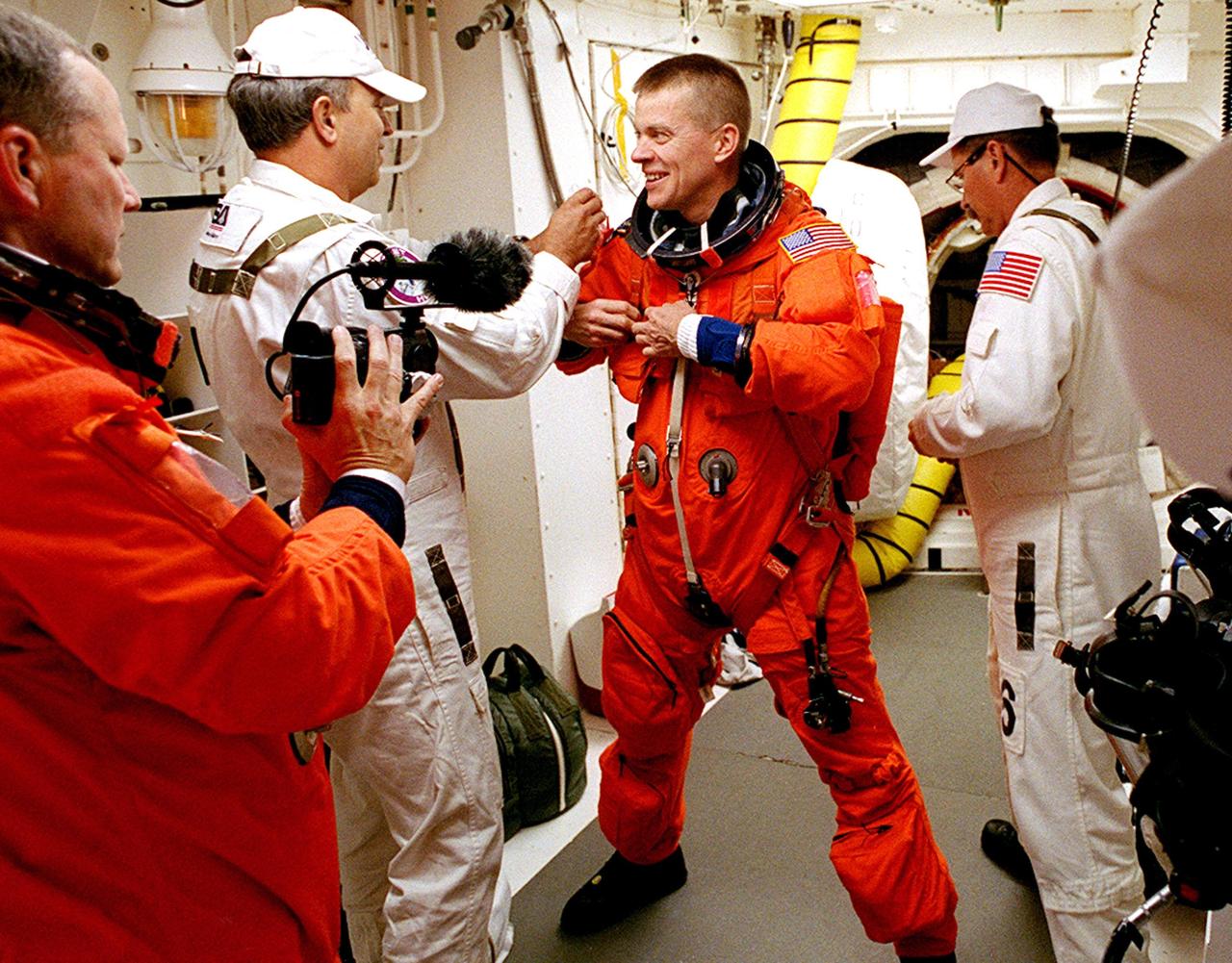
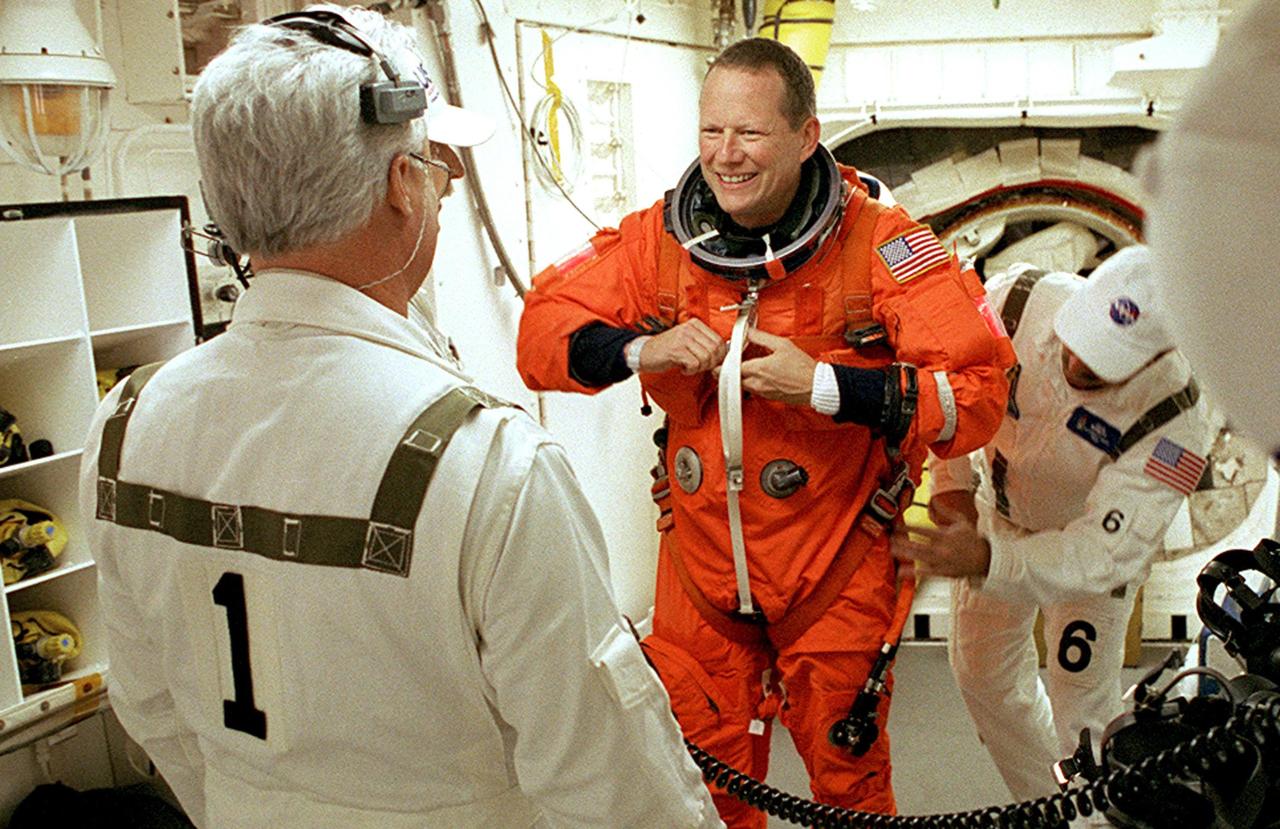
KENNEDY SPACE CENTER, FLA. - STS-107 Pilot William "Willie" McCool (center) gets help with his launch and entry suit from the Closeout Crew in the White Room. The environmentally controlled chamber is mated to Space Shuttle Columbia for entry into the Shuttle. In the foreground, left, is Mission Specialist David Brown. STS-107 is a mission devoted to research and will include more than 80 experiments that will study Earth and space science, advanced technology development, and astronaut health and safety. The payload on Space Shuttle Columbia includes FREESTAR (Fast Reaction Experiments Enabling Science, Technology, Applications and Research) and the SHI Research Double Module (SHI/RDM), known as SPACEHAB. Experiments on the module range from material sciences to life sciences. Liftoff is scheduled for 10:39 a.m. EST.
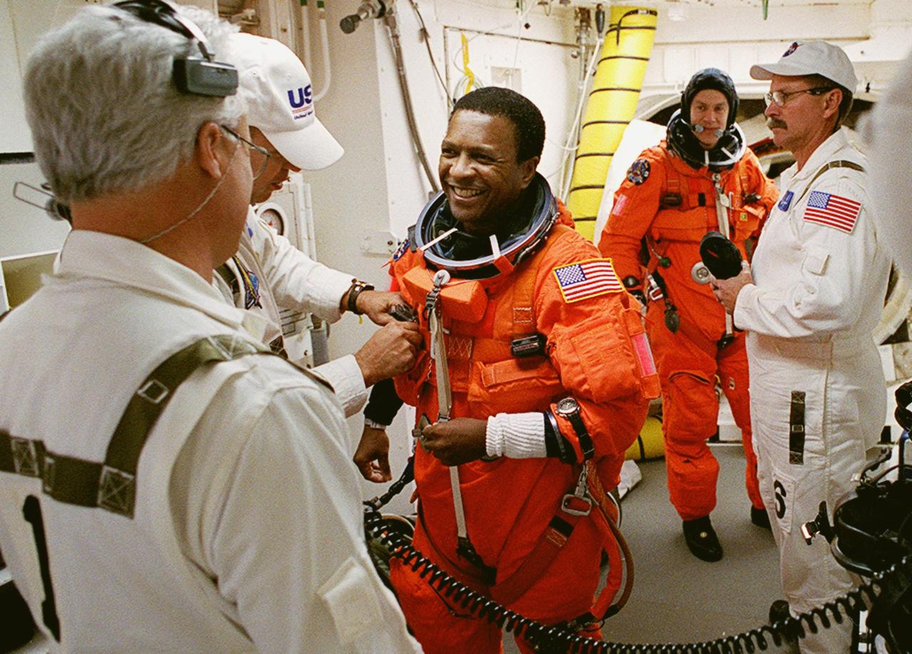
KENNEDY SPACE CENTER, FLA. -- STS-107 Payload Commander Michael Anderson gets help with his launch and entry suit from the Closeout Crew in the White Room. The environmentally controlled chamber is mated to Space Shuttle Columbia for entry into the Shuttle. Behind him is Pilot William "Willie" McCool. STS-107 is a mission devoted to research and will include more than 80 experiments that will study Earth and space science, advanced technology development, and astronaut health and safety. The payload on Space Shuttle Columbia includes FREESTAR (Fast Reaction Experiments Enabling Science, Technology, Applications and Research) and the SHI Research Double Module (SHI/RDM), known as SPACEHAB. Experiments on the module range from material sciences to life sciences. Liftoff is scheduled for 10:39 a.m. EST.
KENNEDY SPACE CENTER, FLA. - STS-107 David Brown chats with the Closeout Crew during final preparations of his launch and entry suit in the White Room. The environmentally controlled chamber is mated to Space Shuttle Columbia for entry into the Shuttle. The hatch is seen in the background right. STS-107 is a mission devoted to research and will include more than 80 experiments that will study Earth and space science, advanced technology development, and astronaut health and safety. The payload on Space Shuttle Columbia includes FREESTAR (Fast Reaction Experiments Enabling Science, Technology, Applications and Research) and the SHI Research Double Module (SHI/RDM), known as SPACEHAB. Experiments on the module range from material sciences to life sciences. Liftoff is scheduled for 10:39 a.m. EST.
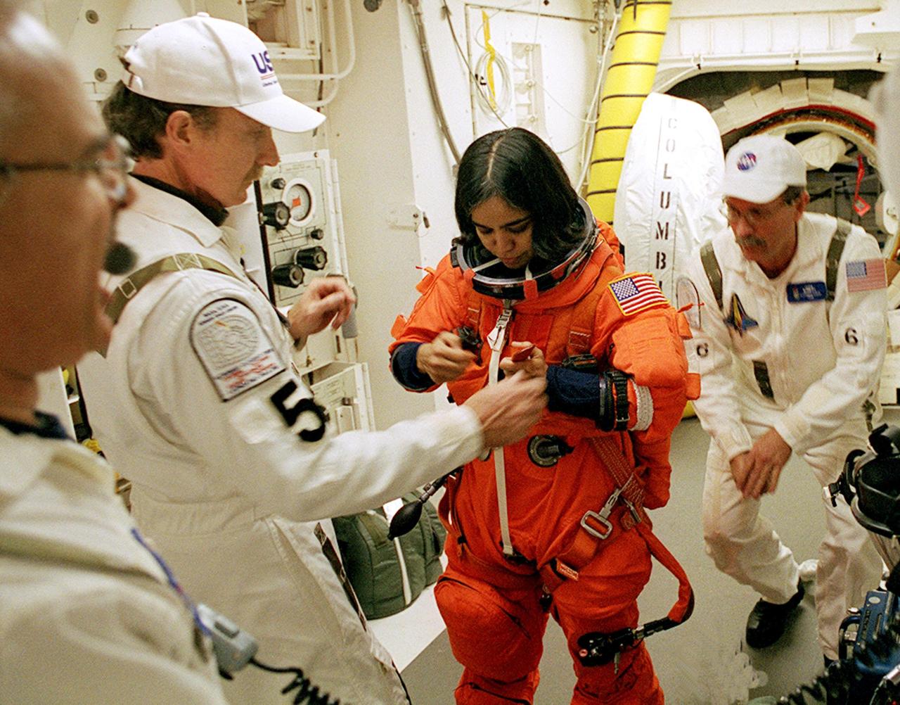
KENNEDY SPACE CENTER, FLA. -- STS-107 Mission Specialist Kalpana Chawla gets help with her launch and entry suit from the Closeout Crew in the White Room. The environmentally controlled chamber is mated to Space Shuttle Columbia for entry into the Shuttle. The hatch is seen in the background right. STS-107 is a mission devoted to research and will include more than 80 experiments that will study Earth and space science, advanced technology development, and astronaut health and safety. The payload on Space Shuttle Columbia includes FREESTAR (Fast Reaction Experiments Enabling Science, Technology, Applications and Research) and the SHI Research Double Module (SHI/RDM), known as SPACEHAB. Experiments on the module range from material sciences to life sciences. Liftoff is scheduled for 10:39 a.m. EST.

KENNEDY SPACE CENTER, FLA. - STS-107 Mission Specialist Laurel Clark waves to a camera out of view during final preparations of her launch and entry suit in the White Room. The environmentally controlled chamber is mated to Space Shuttle Columbia for entry into the Shuttle. The hatch is seen in the background right. STS-107 is a mission devoted to research and will include more than 80 experiments that will study Earth and space science, advanced technology development, and astronaut health and safety. The payload on Space Shuttle Columbia includes FREESTAR (Fast Reaction Experiments Enabling Science, Technology, Applications and Research) and the SHI Research Double Module (SHI/RDM), known as SPACEHAB. Experiments on the module range from material sciences to life sciences. Liftoff is scheduled for 10:39 a.m. EST.
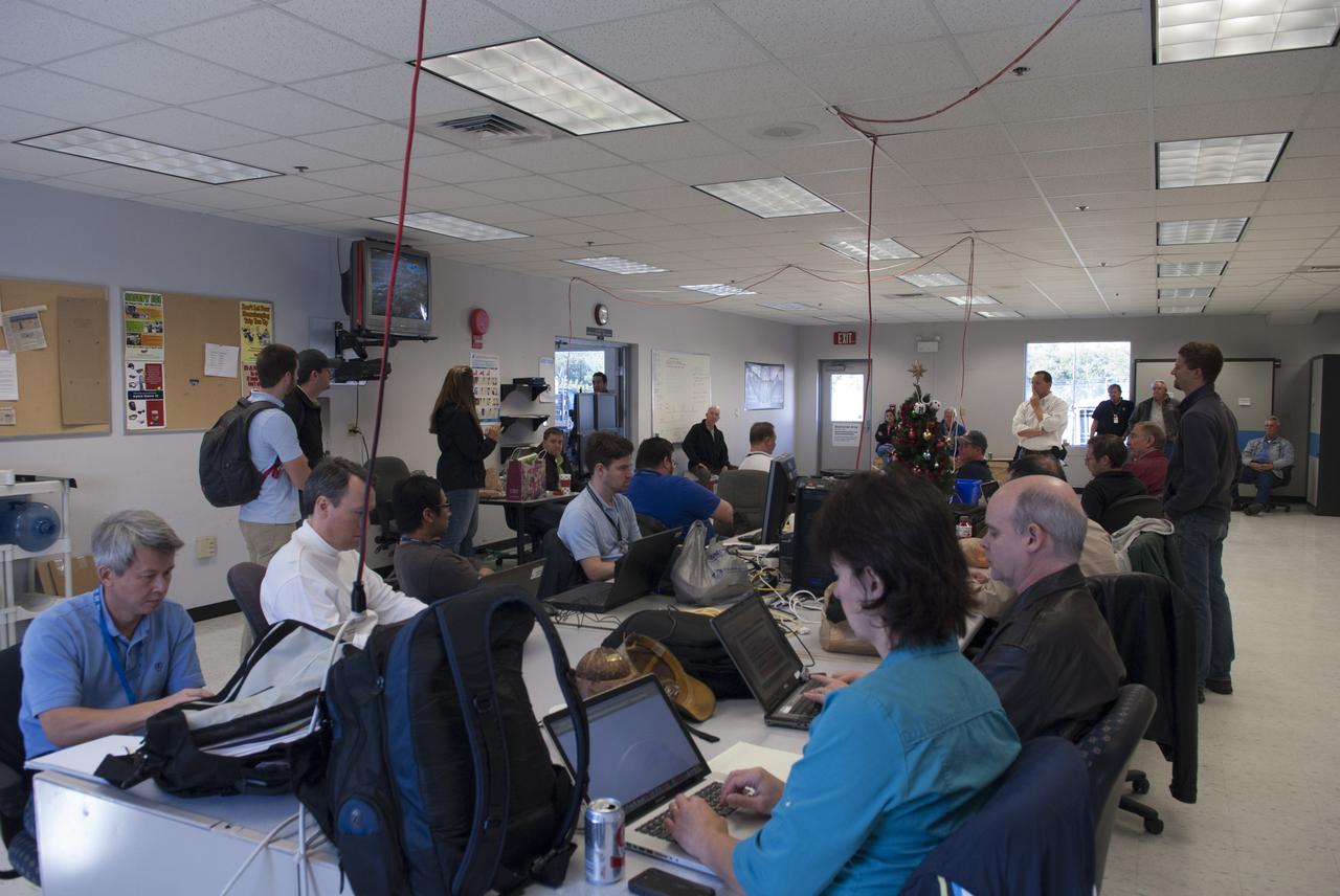
Engineers and controllers in a mobile control room prepare for flight number 15 of NASA's Project Morpheus prototype lander at the north end of the Shuttle Landing Facility, or SLF, at NASA’s Kennedy Space Center in Florida. The lander will take off from the ground over a flame trench and use its autonomous landing and hazard avoidance technology, or ALHAT sensors, to survey the hazard field to determine safe landing sites. Project Morpheus tests NASA’s ALHAT and an engine that runs on liquid oxygen and methane, which are green propellants. These new capabilities could be used in future efforts to deliver cargo to planetary surfaces. Project Morpheus is being managed under the Advanced Exploration Systems, or AES, Division in NASA’s Human Exploration and Operations Mission Directorate.
CAPE CANAVERAL, Fla. – Engineers and controllers in a mobile control room prepare for flight number 15 of NASA's Project Morpheus prototype lander at the north end of the Shuttle Landing Facility, or SLF, at NASA’s Kennedy Space Center in Florida. The lander will take off from the ground over a flame trench and use its autonomous landing and hazard avoidance technology, or ALHAT sensors, to survey the hazard field to determine safe landing sites. Project Morpheus tests NASA’s ALHAT and an engine that runs on liquid oxygen and methane, which are green propellants. These new capabilities could be used in future efforts to deliver cargo to planetary surfaces. Project Morpheus is being managed under the Advanced Exploration Systems, or AES, Division in NASA’s Human Exploration and Operations Mission Directorate. For more information on Project Morpheus, visit http://morpheuslander.jsc.nasa.gov/. Photo credit: NASA/Jim Grossmann
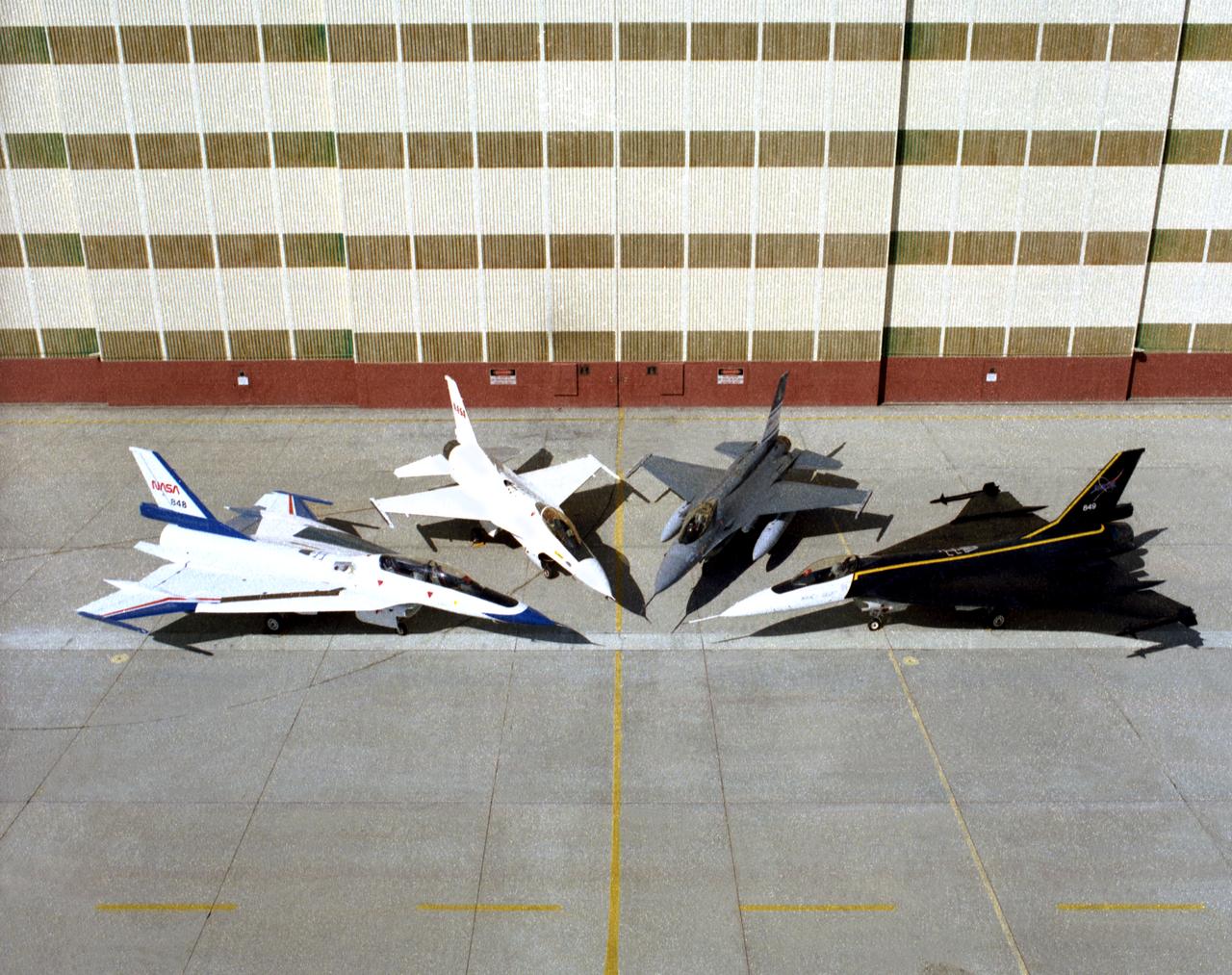
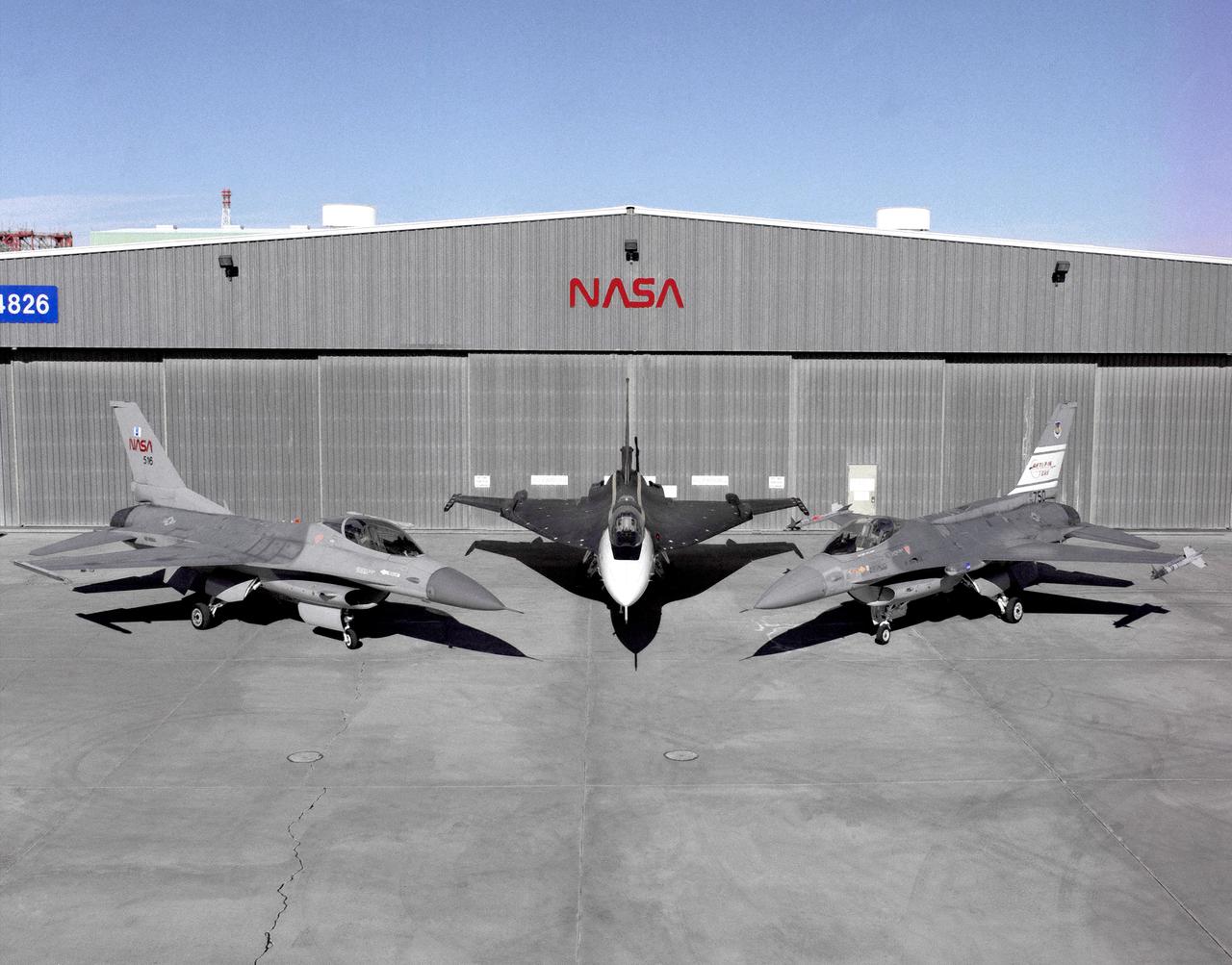
Four different versions of the F-16 were used by Dryden in the 1990s. On the left and right sides are two F-16XLs. On the left is the F-16XL #2 (NASA 848), which is the two-seat version, used for advanced laminar flow studies until late 1996. On the right is the single-seat F-16XL #1 (NASA 849), used for laminar flow research and sonic boom research. (Laminar flow refers to smooth airflow over a wing, which increases lift and reduces drag compared to turbulent airflow). Between them at center left is an F-16A (NASA 816), the only civilian operated F-16. Next to it at center right is the U.S. Air Force Advance Fighter Technology Integration (AFTI) F-16, a program to test new sensor and control technologies for future fighter aircraft. Both F-16XLs are in storage at Dryden. The F-16A was never flown at Dryden, and was parked by the entrance to the center. The AFTI F-16 is in the Air Force Museum.
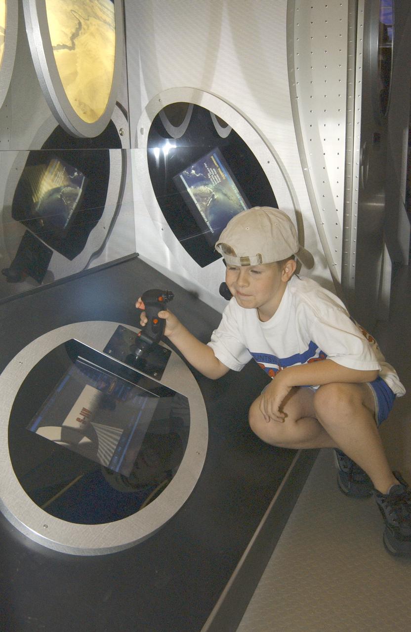
This photograph shows Justin Varnadore, son of a Marshall TV employee, at the controls of one of the many displays within the Starship 2040 exhibit on display at Joe Davis Stadium in Huntsville, Alabama. Developed by the Space Transportation Directorate at Marshall Space Flight Center (MSFC), the Starship 2040 exhibit is housed in a 48-ft (14.6-m) tractor and trailer rig, permitting it to travel around the Nation, demonstrating NASA's vision of what commercial spaceflight might be like 40 years from now. All the irnovations suggested aboard the exhibit (automated vehicle health monitoring systems, high-energy propulsion drive, navigational aids, and emergency and safety systems) are based on concepts and technologies now being studied at NASA Centers and partner institutions around the Nation. NASA is the Nation's premier agency for development of the space transportation system, including future-generation reusable launch vehicles. Such systems, the keys to a "real" Starship 2040, require revolutionary advances in critical aerospace technologies, from thermal, magnetic, chemical, and propellantless propulsion systems to new energy sources such as space solar power or antimatter propulsion. These and other advances are now being studied, developed, and tested at NASA field centers and partner institutions all over the Nation.
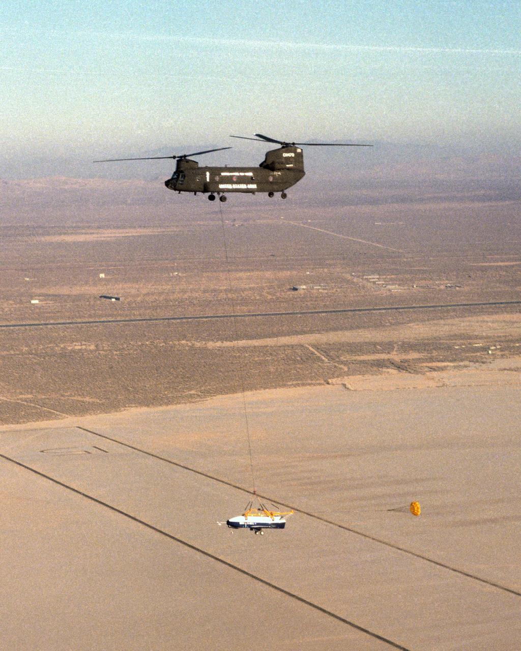
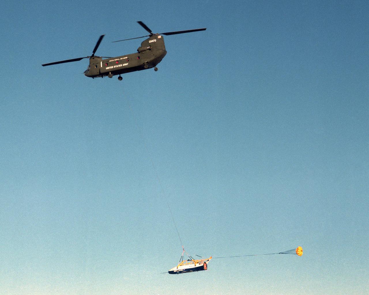
The X-40 sub-scale technology demonstrator and its U.S. Army CH-47 Chinook helicopter mothership fly over a dry lakebed runway during a captive-carry test flight from NASA's Dryden Flight Research Center, Edwards, California. The X-40 is attached to a sling which is suspended from the CH-47 by a 110-foot-long cable during the tests, while a small parachute trails behind to provide stability. The captive carry flights are designed to verify the X-40's navigation and control systems, rigging angles for its sling, and stability and control of the helicopter while carrying the X-40 on a tether. Following a series of captive-carry flights, the X-40 made free flights from a launch altitude of about 15,000 feet above ground, gliding to a fully autonomous landing. The X-40 is an unpowered 82 percent scale version of the X-37, a Boeing-developed spaceplane designed to demonstrate various advanced technologies for development of future lower-cost access to space vehicles.
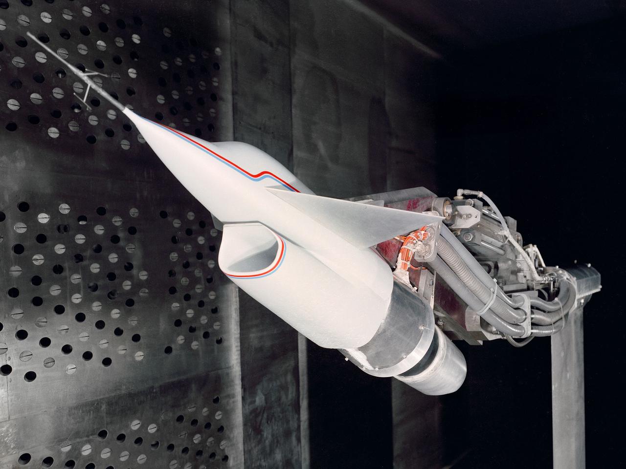
A Highly Maneuverable Aircraft Technology (HiMAT) inlet model installed in the test section of the 8- by 6-Foot Supersonic Wind Tunnel at the National Aeronautics and Space Administration (NASA) Lewis Research Center. Engineers at the Ames Research Center, Dryden Flight Research Center, and Rockwell International designed two pilotless subscale HiMAT vehicles in the mid-1970s to study new design concepts for fighter aircraft in the transonic realm without risking the lives of test pilots. The aircraft used sophisticated technologies such as advanced aerodynamics, composite materials, digital integrated propulsion control, and digital fly-by-wire control systems. In late 1977 NASA Lewis studied the HiMAT’s General Electric J85-21 jet engine in the Propulsion Systems Laboratory. The researchers charted the inlet quality with various combinations anti-distortion screens. HiMAT employed a relatively short and curved inlet compared to actual fighter jets. In the spring of 1979, Larry Smith led an in-depth analysis of the HiMAT inlet in the 8- by 6 tunnel. The researchers installed vortex generators to battle flow separation in the diffuser. The two HiMAT aircraft performed 11 hours of flying over the course of 26 missions from mid-1979 to January 1983 at Dryden and Ames. Although the HiMAT vehicles were considered to be overly complex and expensive, the program yielded a wealth of data that would validate computer-based design tools.

Title: W-8 Fan Acoustic Casing Treatment Test on the Source Diagnostic Test Rotor Alone Hardware Program: Advanced Air Vehicles Program (AAVP) Project: Advanced Air Transport Technology (AATT) Sub-project: Aircraft Noise Reduction (ANR) Weekly Highlight: · Acoustic Casing Treatment Testing Completed in the W-8 Single Stage Axial Compressor Facility: Testing of Acoustic Casing Treatments on the Source Diagnostic Test (SDT) rotor alone hardware which had begun in early January was completed on Thursday, February 16th. Four different over-the-rotor acoustic casing treatment concepts were tested along with two baseline configurations. Testing included steady-aerodynamic measurements of fan performance, hotfilm turbulence measurements, and inlet acoustic measurements with an in-duct array. These measurements will be used to assess the aerodynamic and acoustic impact of fan acoustic casing treatments on a high bypass ratio fan at TRL 3. This test was the last of 3 planned tests of potential over-the-rotor acoustic casing treatments. The first treatment test was completed in the Normal Incidence Tube (NIT) at Langley Research Center (LaRC) in Fall 2015 and the second was completed on the Advanced Noise Control Fan (ANCF) in the Aero-Acoustic Propulsion Laboratory (AAPL) in Winter 2016. This work is supported by the Aircraft Noise Reduction (ANR) subproject of the Advanced Air Transport Technology (AATT) Project. (POC: LTV/ Rick Bozak 3-5160)

Team members pause for a photo after the successful harvest of half the Arabidopsis thaliana plants inside the growth chamber of the Advanced Plant Habitat (APH) Flight Unit No. 1. From right to left are Jeff Richards with Stinger-Ghaffarian Technologies; David Hanson, part of the principal investigator's team; Oscar Monje with NASA Kennedy Space Center's Engineering Services Contract; and John "JC" Carver, a payload integration engineer with Kennedy's Test and Operations Support Contract. The harvest is part of an ongoing verification test of the APH unit, which is located inside the International Space Station Environmental Simulator in Kennedy's Space Station Processing Facility. The APH undergoing testing at Kennedy is identical to one on the station and uses red, green and broad-spectrum white LED lights to grow plants in an environmentally controlled chamber. The seeds grown during the verification test will be grown on the station to help scientists understand how these plants adapt to spaceflight.
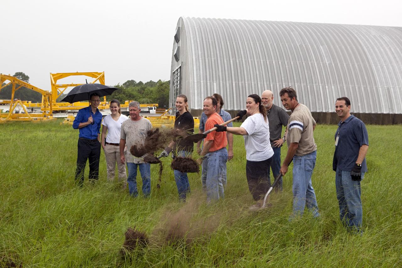
CAPE CANAVERAL, Fla. – Near the Hypergolic Maintenance Facility at NASA’s Kennedy Space Center in Florida, a groundbreaking ceremony was held to mark the location of the Ground Operations Demonstration Unit Liquid Hydrogen, or GODU LH2, test site. From left, are Johnny Nguyen, Fluids Test and Technology Development branch chief Emily Watkins, engineering intern Jeff Walls, Engineering Services Contract, or ESC, Cryogenics Test Lab engineer Kelly Currin, systems engineer Stephen Huff and Rudy Werlink partially hidden, cryogenics engineers Angela Krenn, systems engineer Doug Hammond, command and control engineer in the electrical division William Notardonato, GODU LH2 project manager and Kevin Jumper, ESC Cryogenics Test Lab manager. The GODU LH2 test site is one of the projects in NASA’s Advanced Exploration Systems Program. The site will be used to demonstrate advanced liquid hydrogen systems that are cost and energy efficient ways to store and transfer liquid hydrogen during process, loading, launch and spaceflight. The main components of the site will be a storage tank and a cryogenic refrigerator. Photo credit: NASA/Dimitri Gerondidakis
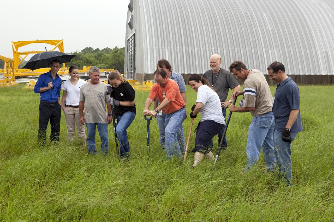
CAPE CANAVERAL, Fla. – Near the Hypergolic Maintenance Facility at NASA’s Kennedy Space Center in Florida, a groundbreaking ceremony was held to mark the location of the Ground Operations Demonstration Unit Liquid Hydrogen, or GODU LH2, test site. From left, are Johnny Nguyen, Fluids Test and Technology Development branch chief Emily Watkins, engineering intern Jeff Walls, Engineering Services Contract, or ESC, Cryogenics Test Lab engineer Kelly Currin, systems engineer Stephen Huff and Rudy Werlink partially hidden, cryogenics engineers Angela Krenn, systems engineer Doug Hammond, command and control engineer in the electrical division William Notardonato, GODU LH2 project manager and Kevin Jumper, ESC Cryogenics Test Lab manager. The GODU LH2 test site is one of the projects in NASA’s Advanced Exploration Systems Program. The site will be used to demonstrate advanced liquid hydrogen systems that are cost and energy efficient ways to store and transfer liquid hydrogen during process, loading, launch and spaceflight. The main components of the site will be a storage tank and a cryogenic refrigerator. Photo credit: NASA/Dimitri Gerondidakis
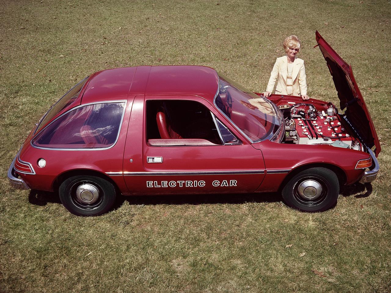
The National Aeronautics and Space Administration (NASA) Lewis Research Center tested 16 commercially-manufactured electric vehicles, including this modified Pacer, during the mid-1970s. The Electric Vehicle Project was just one of several energy-related programs that Lewis and the Energy Research and Development Administration (ERDA) undertook in the mid-1970s. NASA and ERDA embarked on this program in 1976 to determine the state of the current electric vehicle technology. As part of the project, Lewis tested a fleet composed of every commercially available electric car. The Cleveland-area Electric Vehicle Associates modified an American Motors Pacer vehicle to create this Change-of-Pace Coupe. It was powered by twenty 6-volt batteries whose voltage could be varied by a foot control. The tests analyzed the vehicle’s range, acceleration, coast-down, braking, and energy consumption. Some of the vehicles had analog data recording systems to measure the battery during operation and sensors to determine speed and distance. Lewis researchers found that the vehicle performance varied significantly from model to model. In general, the range, acceleration, and speed were lower than conventional vehicles. They also found that traditional gasoline-powered vehicles were as efficient as the electric vehicles. The researchers concluded, however, that advances in battery technology and electric drive systems would significantly improve the performance and efficiency.
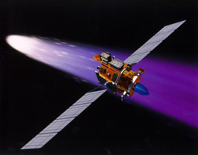
NASA's New Millennium Deep Space 1 spacecraft approaching the comet 19P/Borrelly. With its primary mission to serve as a technology demonstrator--testing ion propulsion and 11 other advanced technologies--successfully completed in September 1999, Deep Space 1 is now headed for a risky, exciting rendezvous with Comet Borrelly. NASA extended the mission, taking advantage of the ion propulsion and other systems to target the daring encounter with the comet in September 2001. Once a sci-fi dream, the ion propulsion engine has powered the spacecraft for over 12,000 hours. Another onboard experiment includes software that tracks celestial bodies so the spacecraft can make its own navigation decisions without the intervention of ground controllers. The first flight in NASA's New Millennium Program, Deep Space 1 was launched October 24, 1998 aboard a Boeing Delta 7326 rocket from Cape Canaveral Air Station, FL. Deep Space 1 successfully completed and exceeded its mission objectives in July 1999 and flew by a near-Earth asteroid, Braille (1992 KD), in September 1999. http://photojournal.jpl.nasa.gov/catalog/PIA04604
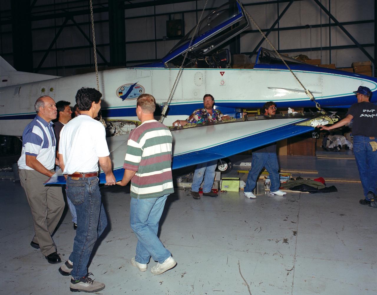
U.S. and German personnel of the X-31 Enhanced Fighter Maneuverability Technology Demonstrator aircraft program removing the right wing of the aircraft, which was ferried from Edwards Air Force Base, California, to Europe on May 22, 1995 aboard an Air Force Reserve C-5 transport. The X-31, based at the NASA Dryden Flight Research Center was ferried to Europe and flown in the Paris Air Show in June. The wing of the X-31 was removed on May 18, 1995, to allow the aircraft to fit inside the C-5 fuselage. Officials of the X-31 project used Manching, Germany, as a staging base to prepare the aircraft for the flight demonstration. At the air show, the X-31 demonstrated the value of using thrust vectoring (directing engine exhaust flow) coupled with advanced flight control systems to provide controlled flight at very high angles of attack. The aircraft arrived back at Edwards in a Air Force Reserve C-5 on June 25, 1995 and off loaded at Dryden June 27. The X-31 aircraft was developed jointly by Rockwell International's North American Aircraft Division (now part of Boeing) and Daimler-Benz Aerospace (formerly Messerschmitt-Bolkow-Blohm), under sponsorship by the U.S. Department of Defense and the German Federal Ministry of Defense.
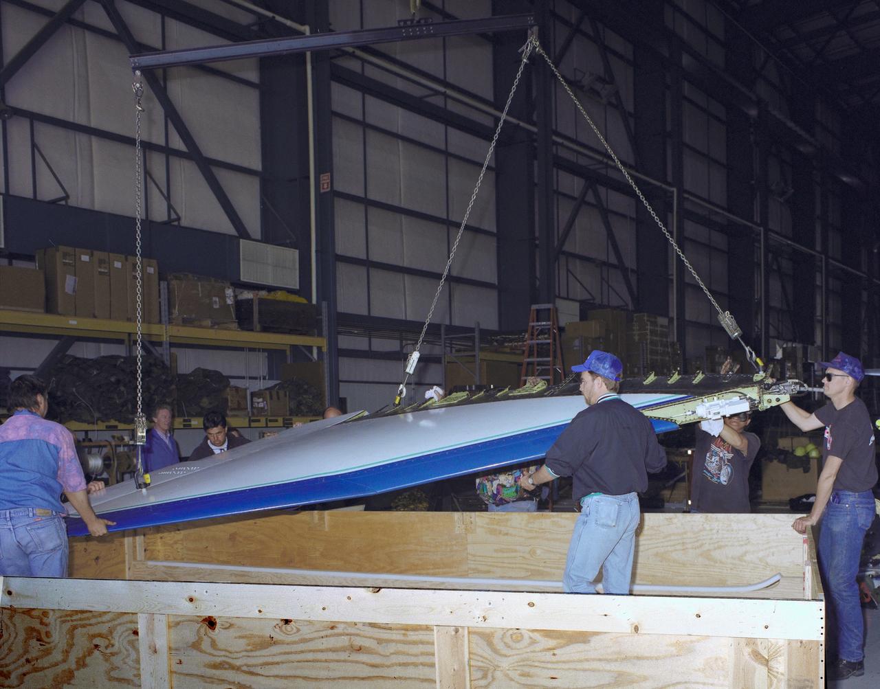
The right wing of the X-31 Enhanced Fighter Maneuverability Technology Demonstrator Aircraft is seen here being put into a shipping container May 18, 1995, at NASA's Dryden Flight Research Center, Edwards, California, by U.S. and German members of the program. To fit inside an Air Force Reserve C-5 transport, which was used to ferry the X-31 to Europe on May 22, 1995, the right wing had to be removed. Manching, Germany, was used as a staging base to prepare the aircraft for participation in the Paris Air Show. At the air show on June 11 through the 18th, the X-31 demonstrated the value of using thrust vectoring (directing engine exhaust flow) coupled with advanced flight control systems to provide controlled flight at very high angles of attack. The aircraft arrived back at Edwards in an Air Force Reserve C-5 on June 25, 1995, and off loaded at Dryden the 27th. The X-31 aircraft was developed jointly by Rockwell International's North American Aircraft Division (now part of Boeing) and Daimler-Benz Aerospace (formerly Messerschmitt-Bolkow-Blohm), under sponsorship by the U.S. Department of Defense and the German Federal Ministry of Defense.
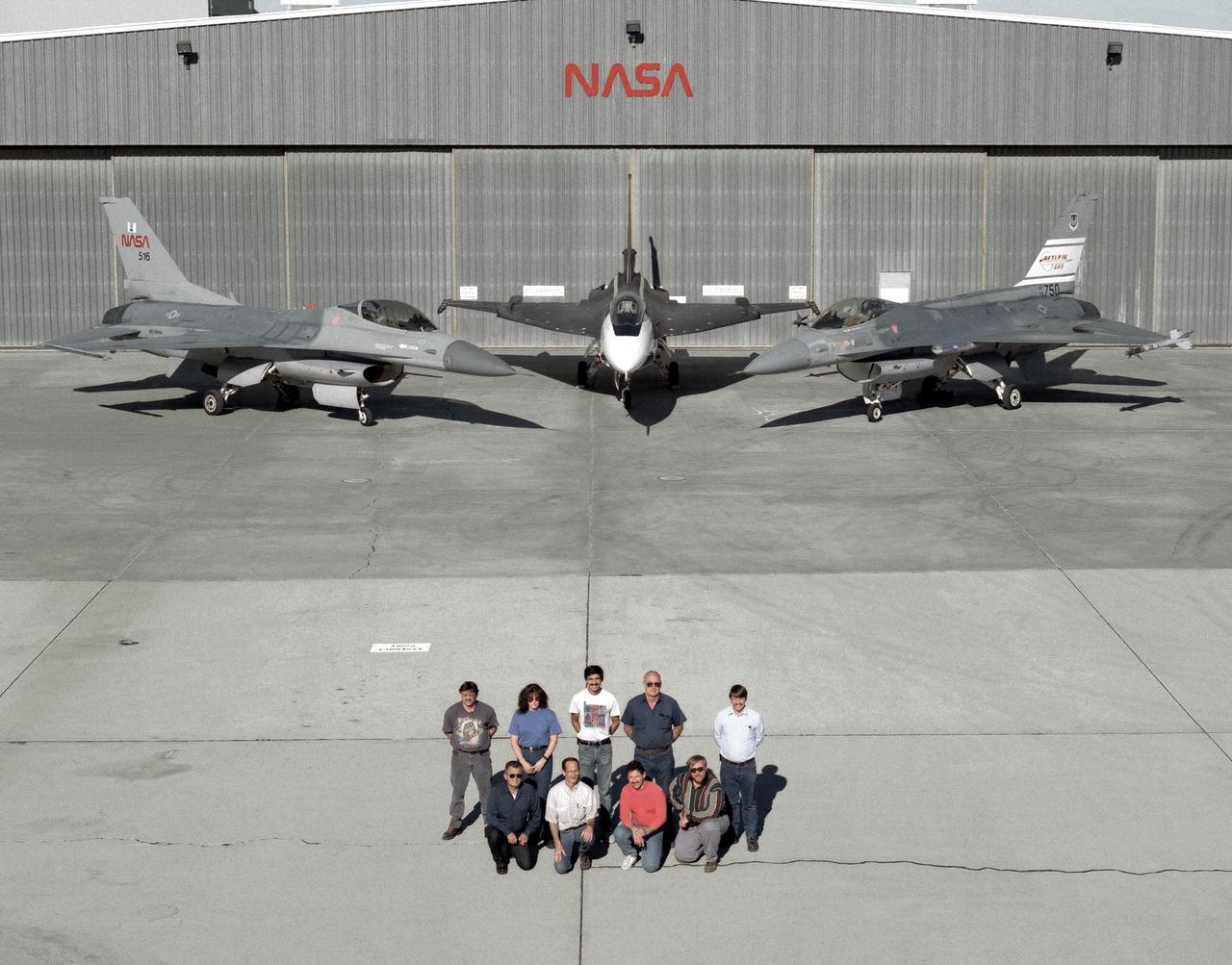
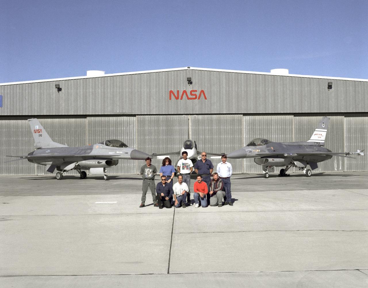
The support crew for the F-16A, the F-16XL no. 1, and the F-16 AFTI are, top row, left to right: Randy Weaver; mechanic, Susan Ligon; mechanic, Bob Garcia; Crew Chief, Rich Kelly; mechanic, Dale Edminister; Avionics Technician. Bottom row, left to right, Art Cope; mechanic, John Huffman; Avionics Technician, Jaime Garcia; Avionics Technician, Don Griffith, Avionics Tech. Co-op student. The F-16A (NASA 516), the only civil registered F-16 in existence, was transferred to Dryden from Langley, and was primarily used in engine tests and for parts. It was subsequently transfered from Dryden. The single-seat F-16XL no. 1 (NASA 849) was most recently used in the Cranked-Arrow Wing Aerodynamics Project (CAWAP) to test boundary layer pressures and distribution. Previously it had been used in a program to investigate the characteristics of sonic booms for NASA's High Speed Research Program. Data from the program will be used in the development of a high speed civilian transport. During the series of sonic boom research flights, the F-16XL was used to probe the shock waves being generated by a NASA SR-71 and record their shape and intensity. The Advanced Fighter Technology Integration (AFTI) F-16 was used to develop and demonstrate technologies to improve navigation and a pilot's ability to find and destroy enemy ground targets day or night, including adverse weather. Earlier research in the joint NASA-Air Force AFTI F-16 program demonstrated voice actuated controls, helmet-mounted sighting and integration of forward-mounted canards with the standard flight control system to achieve uncoupled flight.
The support crew for the F-16A, the F-16XL no. 1, and the F-16 AFTI are, top row, left to right: Randy Weaver; mechanic, Susan Ligon; mechanic, Bob Garcia; Crew Chief, Rich Kelly; mechanic, Dale Edminister; Avionics Technician. Bottom row, left to right, Art Cope; mechanic, John Huffman; Avionics Technician, Jaime Garcia; Avionics Technician, Don Griffith, Avionics Tech. Co-op student. The F-16A (NASA 516), the only civil registered F-16 in existence, was transferred to Dryden from Langley, and was primarily used in engine tests and for parts. It was subsequently transfered from Dryden. The single-seat F-16XL no. 1 (NASA 849) was most recently used in the Cranked-Arrow Wing Aerodynamics Project (CAWAP) to test boundary layer pressures and distribution. Previously it had been used in a program to investigate the characteristics of sonic booms for NASA's High Speed Research Program. Data from the program will be used in the development of a high speed civilian transport. During the series of sonic boom research flights, the F-16XL was used to probe the shock waves being generated by a NASA SR-71 and record their shape and intensity. The Advanced Fighter Technology Integration (AFTI) F-16 was used to develop and demonstrate technologies to improve navigation and a pilot's ability to find and destroy enemy ground targets day or night, including adverse weather. Earlier research in the joint NASA-Air Force AFTI F-16 program demonstrated voice actuated controls, helmet-mounted sighting and integration of forward-mounted canards with the standard flight control system to achieve uncoupled flight.
Photographed outside their hangar at the Dryden Flight Research Center, Edwards, California, part of Dryden's F-16 fleet is, left to right; an F-16A, the F-16XL no. 1, and the F-16 AFTI. The F-16A (NASA 516), the only civil registered F-16 in existence, was transferred to Dryden from Langley, and was primarily used in engine tests and for parts. It was subsequently transfered from Dryden. The single-seat F-16XL no. 1 (NASA 849) was most recently used in the Cranked-Arrow Wing Aerodynamics Project (CAWAP) to test boundary layer pressures and distribution. Previously it had been used in a program to investigate the characteristics of sonic booms for NASA's High Speed Research Program. Data from the program will be used in the development of a high speed civilian transport. During the series of sonic boom research flights, the F-16XL was used to probe the shock waves being generated by a NASA SR-71 and record their shape and intensity. The Advanced Fighter Technology Integration (AFTI) F-16 was used to develop and demonstrate technologies to improve navigation and a pilot's ability to find and destroy enemy ground targets day or night, including adverse weather. Earlier research in the joint NASA-Air Force AFTI F-16 program demonstrated voice actuated controls, helmet-mounted sighting and integration of forward-mounted canards with the standard flight control system to achieve uncoupled flight.
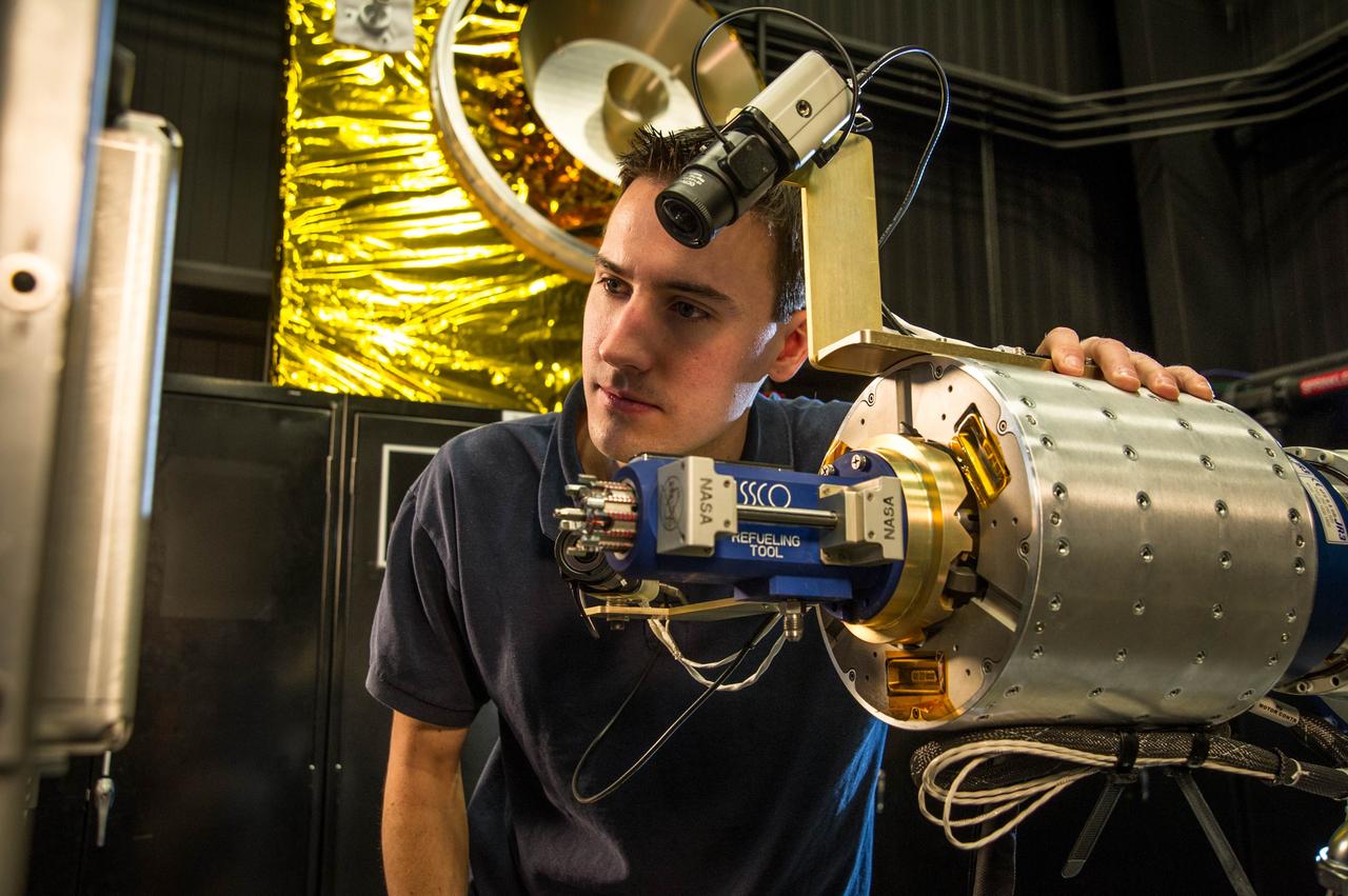
RROxiTT lead roboticist Alex Janas stands with the Oxidizer Nozzle Tool as he examines the work site. Credit: NASA/Goddard/Chris Gunn NASA has successfully concluded a remotely controlled test of new technologies that would empower future space robots to transfer hazardous oxidizer – a type of propellant – into the tanks of satellites in space today. Concurrently on the ground, NASA is incorporating results from this test and the Robotic Refueling Mission on the International Space Station to prepare for an upcoming ground-based test of a full-sized robotic servicer system that will perform tasks on a mock satellite client. Collectively, these efforts are part of an ongoing and aggressive technology development campaign to equip robots and humans with the tools and capabilities needed for spacecraft maintenance and repair, the assembly of large space telescopes, and extended human exploration. Read more here: <a href="http://www.nasa.gov/content/goddard/nasa-tests-new-robotic-refueling-technologies/#.UxeLyyRkLH4" rel="nofollow">www.nasa.gov/content/goddard/nasa-tests-new-robotic-refue...</a> <b><a href="http://www.nasa.gov/audience/formedia/features/MP_Photo_Guidelines.html" rel="nofollow">NASA image use policy.</a></b> <b><a href="http://www.nasa.gov/centers/goddard/home/index.html" rel="nofollow">NASA Goddard Space Flight Center</a></b> enables NASA’s mission through four scientific endeavors: Earth Science, Heliophysics, Solar System Exploration, and Astrophysics. Goddard plays a leading role in NASA’s accomplishments by contributing compelling scientific knowledge to advance the Agency’s mission. <b>Follow us on <a href="http://twitter.com/NASAGoddardPix" rel="nofollow">Twitter</a></b> <b>Like us on <a href="http://www.facebook.com/pages/Greenbelt-MD/NASA-Goddard/395013845897?ref=tsd" rel="nofollow">Facebook</a></b> <b>Find us on <a href="http://instagram.com/nasagoddard?vm=grid" rel="nofollow">Instagram</a></b>
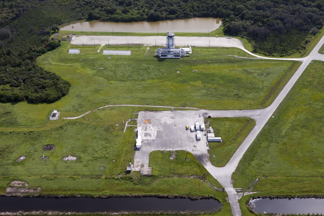
CAPE CANAVERAL, Fla. – This aerial view shows the Shuttle Landing Facility’s air traffic control tower at the Kennedy Space Center in Florida. Just below the tower is the mid-field park site used for runway support vehicles. At the north end of the runway, a rock and crater-filled planetary scape has been built so engineers can test the Autonomous Landing and Hazard Avoidance Technology, or ALHAT system on the Project Morpheus lander. Testing will demonstrate ALHAT’s ability to provide required navigation data negotiating the Morpheus lander away from risks during descent. Checkout of the prototype lander has been ongoing at NASA’s Johnson Space Center in Houston in preparation for its first free flight. The SLF site will provide the lander with the kind of field necessary for realistic testing. Project Morpheus is one of 20 small projects comprising the Advanced Exploration Systems, or AES, program in NASA’s Human Exploration and Operations Mission Directorate. AES projects pioneer new approaches for rapidly developing prototype systems, demonstrating key capabilities and validating operational concepts for future human missions beyond Earth orbit. For more information on Project Morpheus, visit http://www.nasa.gov/centers/johnson/exploration/morpheus/index.html Photo credit: NASA/Kim Shiflett
CAPE CANAVERAL, Fla. – At NASA’s Kennedy Space Center in Florida, NASA Administrator Charles Bolden joins Morpheus project manager Dr. Jon Olansen, pointing at monitor, in the control room at the Shuttle Landing Facility for the first tethered flight of the Morpheus lander. After undergoing testing at Johnson Space Center in Houston for nearly a year, Morpheus arrived at Kennedy on July 27 to begin about three months of tests. A field, replete with boulders, rocks, slopes, craters and hazards to avoid, was created at the north end of Kennedy's runway to provide a realistic landscape for test flights of the lander. Morpheus utilizes autonomous landing and hazard avoidance technology, or ALHAT, to navigate to a safe landing site during its descent. Project Morpheus is one of 20 small projects comprising the Advanced Exploration Systems, or AES, program in NASA's Human Exploration and Operations Mission Directorate. AES projects pioneer new approaches for rapidly developing prototype systems, demonstrating key capabilities and validating operational concepts for future human missions beyond Earth orbit. For more information on Project Morpheus, visit http://www.nasa.gov/centers/johnson/exploration/morpheus/index.html. Photo credit: NASA/Kim Shiflett
CubeSail is a nano-scale flight experiment to demonstrate deployment and control of a single 250-meter (20 m2) solar sail blade as a low-cost risk reduction precursor of the exciting advanced interplanetary UltraSail concept having four 5-kilometer blades (with approximately 100,000 m2 of sail area). CubeSail was built by the University of Illinois at Urbana-Champaign and CU Aerospace, the same team that designed the I-Sail and UltraSail concepts funded by NASA’s SBIR program. CubeSail represents an affordable stepping-stone towards the future development of the UltraSail solar sail concept that would enable very high-energy inner heliosphere and interstellar scientific missions. In addition, near-earth missions such as Heliostorm for early warning of solar storms will provide more warning margin as the solar sail performance is increased with UltraSail technology. Spacecraft design studies show that for sail areal densities below 5 gm/m2, as proposed with UltraSail, that spacecraft payloads can be significantly increased to 50-60% because of the elimination of the propellant, without sacrificing flight time. Furthermore, higher payload fractions will result in dramatically lower total spacecraft mass and consequently much lower launch cost, enabling more missions for the research dollar.
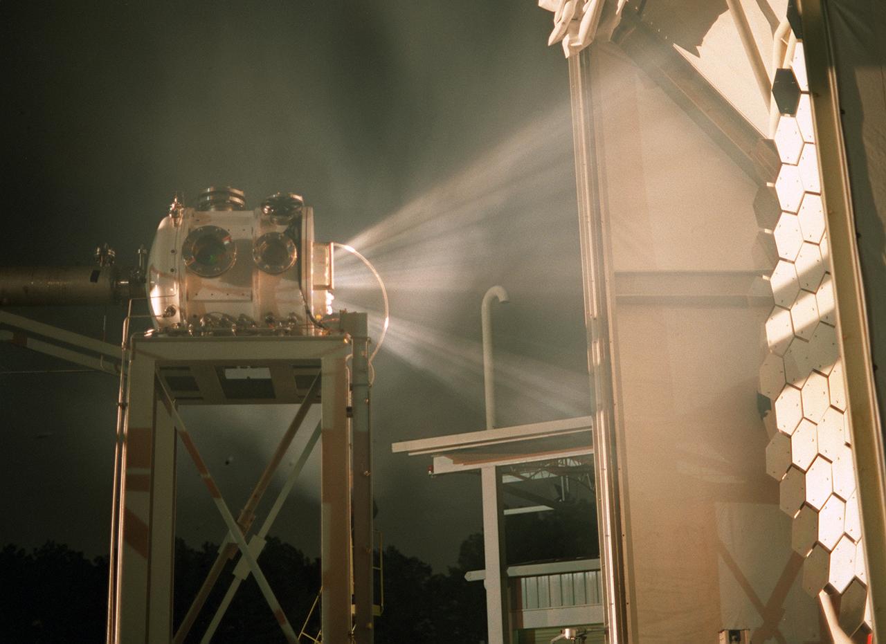
Researchers at the Marshall Space Flight Center (MSFC) have designed, fabricated, and tested the first solar thermal engine, a non-chemical rocket engine that produces lower thrust but has better thrust efficiency than a chemical combustion engine. MSFC turned to solar thermal propulsion in the early 1990s due to its simplicity, safety, low cost, and commonality with other propulsion systems. Solar thermal propulsion works by acquiring and redirecting solar energy to heat a propellant. The 20- by 24-ft heliostat mirror (not shown in this photograph) has a dual-axis control that keeps a reflection of the sunlight on the 18-ft diameter concentrator mirror, which then focuses the sunlight to a 4-in focal point inside the vacuum chamber. The focal point has 10 kilowatts of intense solar power. This image, taken during the test, depicts the light being concentrated into the focal point inside the vacuum chamber. As part of MSFC's Space Transportation Directorate, the Propulsion Research Center serves as a national resource for research of advanced, revolutionary propulsion technologies. The mission is to move the Nation's capabilities beyond the confines of conventional chemical propulsion into an era of aircraft-like access to Earth orbit, rapid travel throughout the solar system, and exploration of interstellar space.
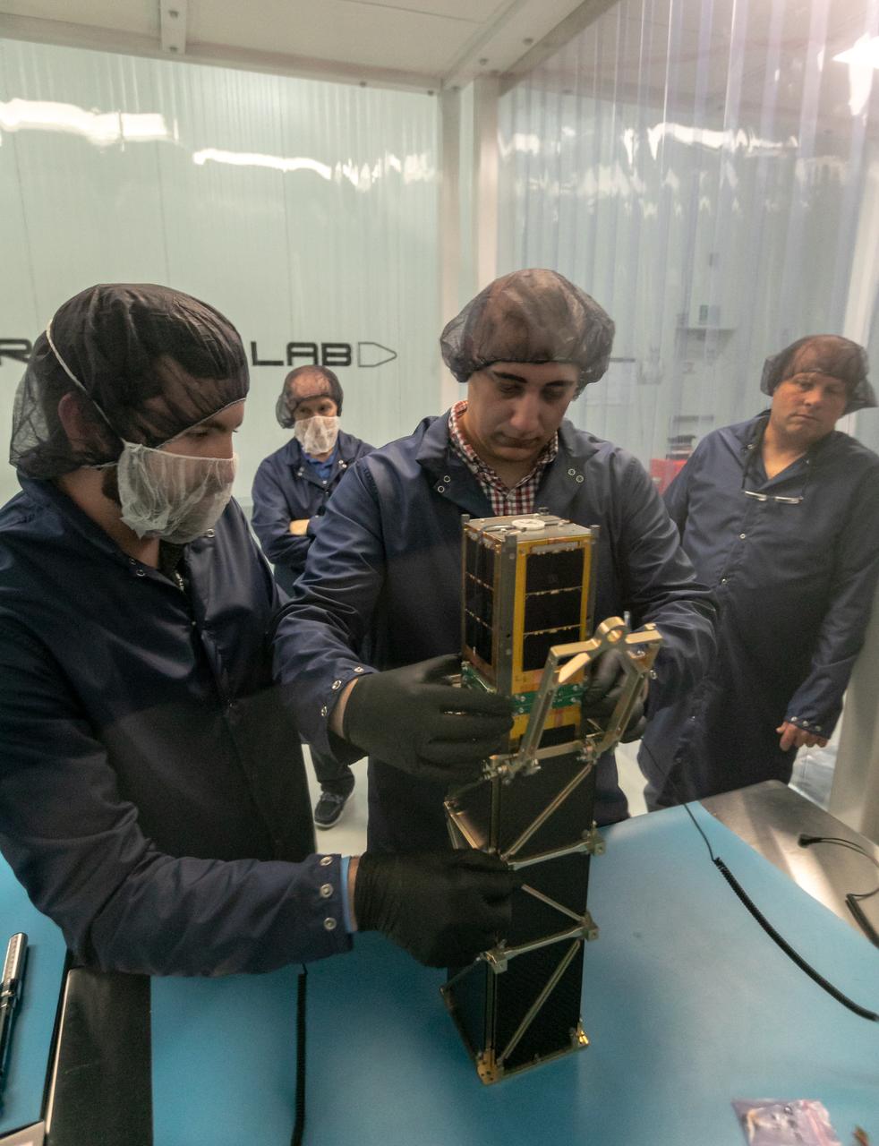
CubeSail is a nano-scale flight experiment to demonstrate deployment and control of a single 250-meter (20 m2) solar sail blade as a low-cost risk reduction precursor of the exciting advanced interplanetary UltraSail concept having four 5-kilometer blades (with approximately 100,000 m2 of sail area). CubeSail was built by the University of Illinois at Urbana-Champaign and CU Aerospace, the same team that designed the I-Sail and UltraSail concepts funded by NASA’s SBIR program. CubeSail represents an affordable stepping-stone towards the future development of the UltraSail solar sail concept that would enable very high-energy inner heliosphere and interstellar scientific missions. In addition, near-earth missions such as Heliostorm for early warning of solar storms will provide more warning margin as the solar sail performance is increased with UltraSail technology. Spacecraft design studies show that for sail areal densities below 5 gm/m2, as proposed with UltraSail, that spacecraft payloads can be significantly increased to 50-60% because of the elimination of the propellant, without sacrificing flight time. Furthermore, higher payload fractions will result in dramatically lower total spacecraft mass and consequently much lower launch cost, enabling more missions for the research dollar.
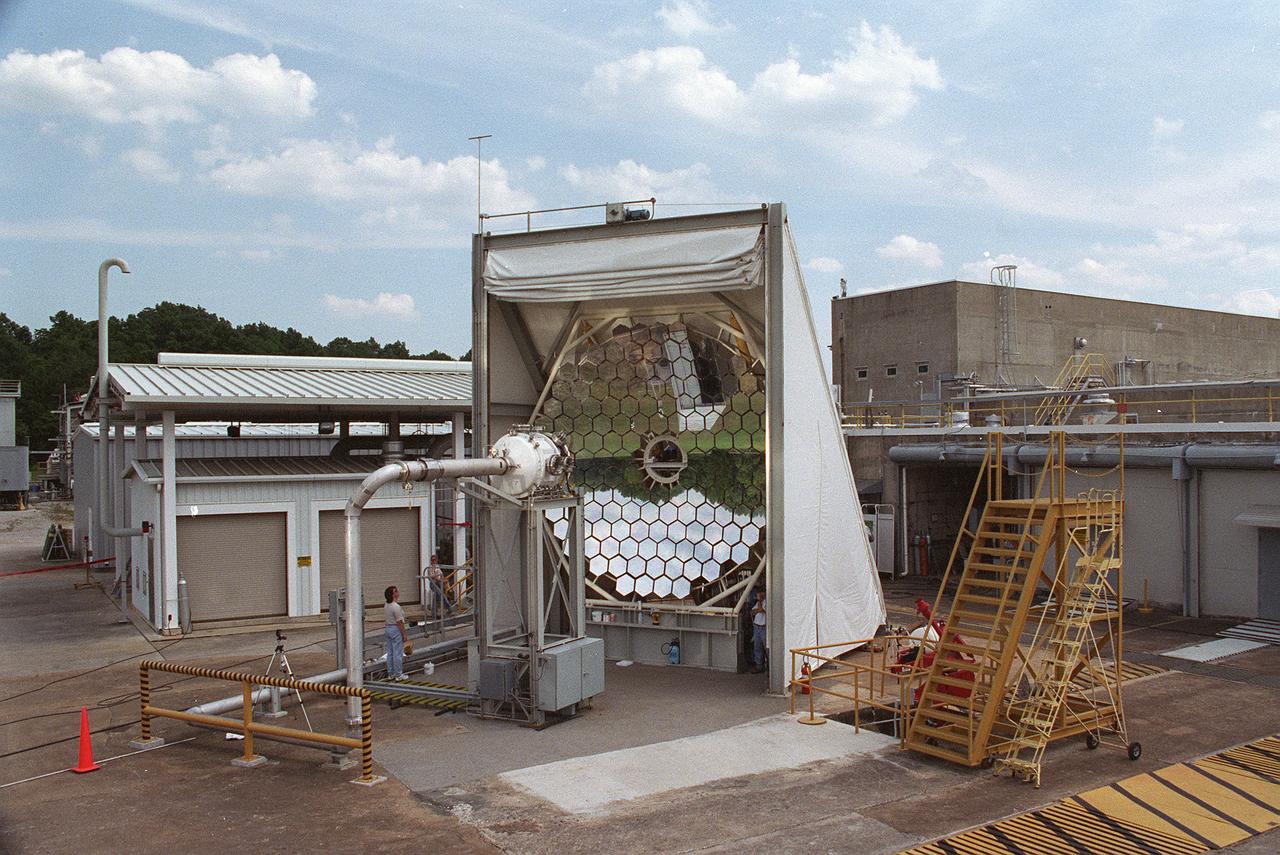
Researchers at the Marshall Space Flight Center (MSFC) have designed, fabricated and tested the first solar thermal engine, a non-chemical rocket engine that produces lower thrust but has better thrust efficiency than a chemical combustion engine. MSFC turned to solar thermal propulsion in the early 1990s due to its simplicity, safety, low cost, and commonality with other propulsion systems. Solar thermal propulsion works by acquiring and redirecting solar energy to heat a propellant. This photograph, taken at MSFC's Solar Thermal Propulsion Test Facility, shows a concentrator mirror, a combination of 144 mirrors forming this 18-ft diameter concentrator, and a vacuum chamber that houses the focal point. The 20- by 24-ft heliostat mirror (not shown in this photograph) has a dual-axis control that keeps a reflection of the sunlight on the 18-foot diameter concentrator mirror, which then focuses the sunlight to a 4-in focal point inside the vacuum chamber. The focal point has 10 kilowatts of intense solar power. As part of MSFC's Space Transportation Directorate, the Propulsion Research Center serves as a national resource for research of advanced, revolutionary propulsion technologies. The mission is to move the Nation's capabilities beyond the confines of conventional chemical propulsion into an era of aircraft-like access to Earth-orbit, rapid travel throughout the solar system, and exploration of interstellar space.
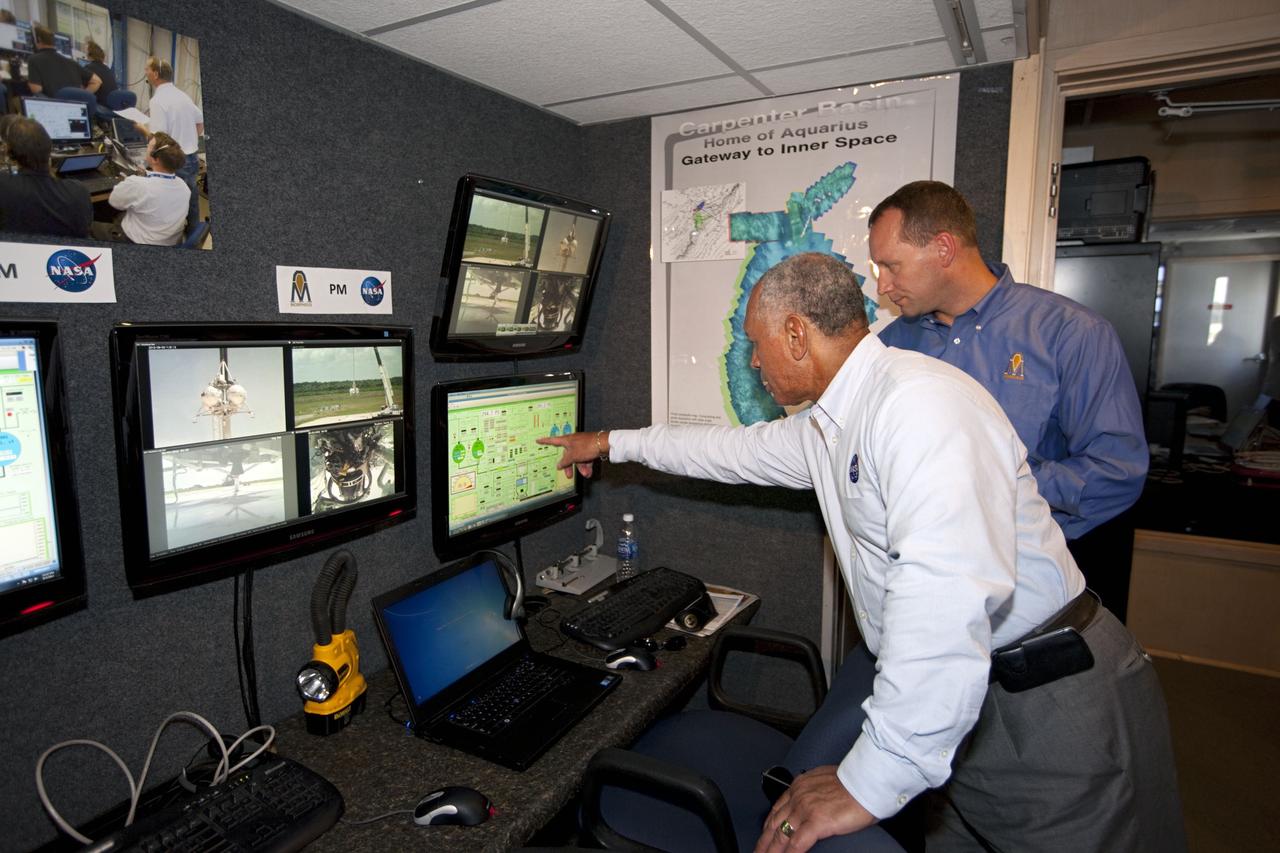
CAPE CANAVERAL, Fla. – At NASA’s Kennedy Space Center in Florida, NASA Administrator Charles Bolden, left, joins Dr. Jon Olansen, Morpheus project manager, in the control room at the Shuttle Landing Facility for the first tethered flight of the Morpheus lander. After undergoing testing at Johnson Space Center in Houston for nearly a year, Morpheus arrived at Kennedy on July 27 to begin about three months of tests. A field, replete with boulders, rocks, slopes, craters and hazards to avoid, was created at the north end of Kennedy's runway to provide a realistic landscape for test flights of the lander. Morpheus utilizes autonomous landing and hazard avoidance technology, or ALHAT, to navigate to a safe landing site during its descent. Project Morpheus is one of 20 small projects comprising the Advanced Exploration Systems, or AES, program in NASA's Human Exploration and Operations Mission Directorate. AES projects pioneer new approaches for rapidly developing prototype systems, demonstrating key capabilities and validating operational concepts for future human missions beyond Earth orbit. For more information on Project Morpheus, visit http://www.nasa.gov/centers/johnson/exploration/morpheus/index.html. Photo credit: NASA/Kim Shiflett
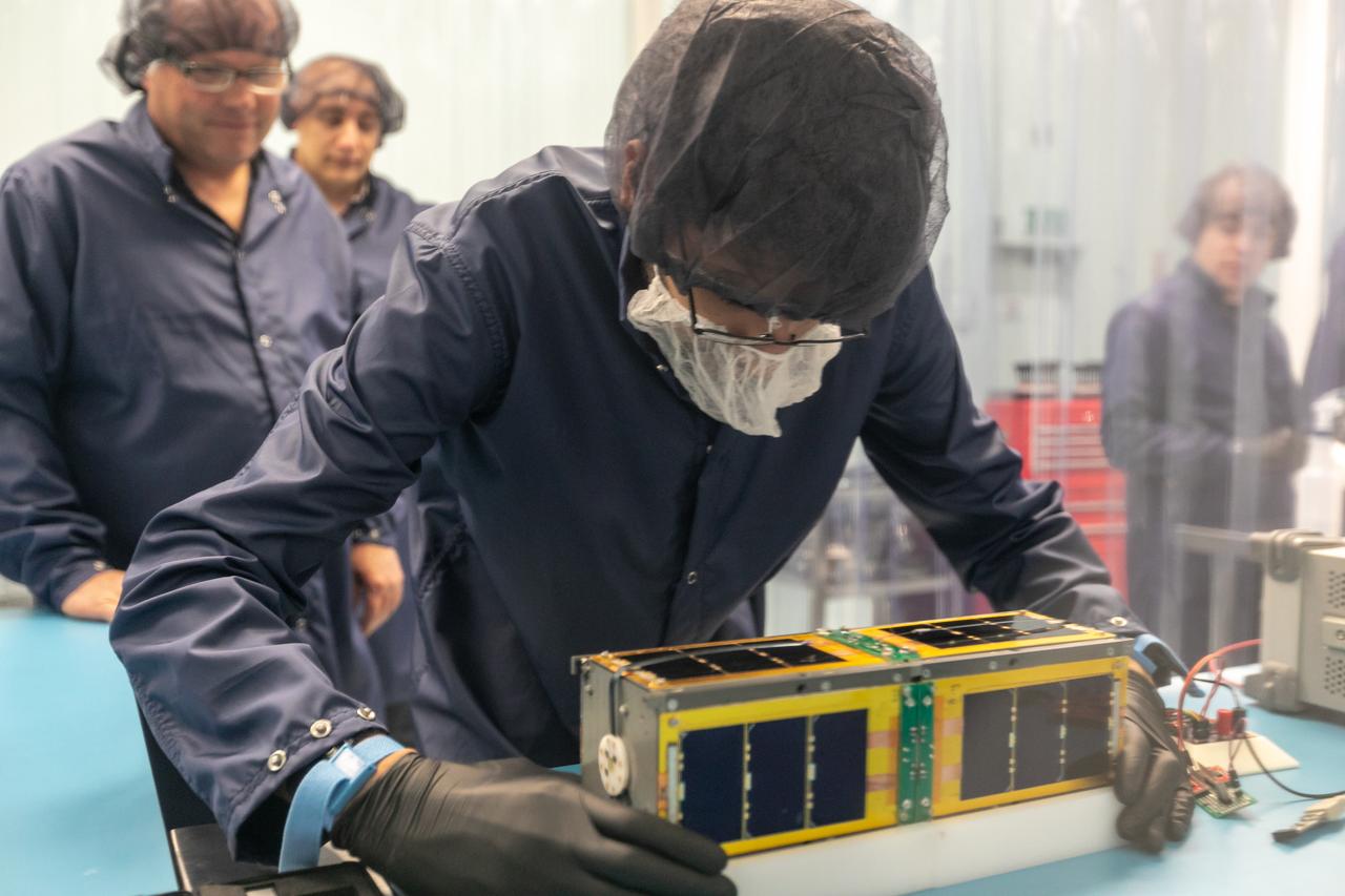
CubeSail is a nano-scale flight experiment to demonstrate deployment and control of a single 250-meter (20 m2) solar sail blade as a low-cost risk reduction precursor of the exciting advanced interplanetary UltraSail concept having four 5-kilometer blades (with approximately 100,000 m2 of sail area). CubeSail was built by the University of Illinois at Urbana-Champaign and CU Aerospace, the same team that designed the I-Sail and UltraSail concepts funded by NASA’s SBIR program. CubeSail represents an affordable stepping-stone towards the future development of the UltraSail solar sail concept that would enable very high-energy inner heliosphere and interstellar scientific missions. In addition, near-earth missions such as Heliostorm for early warning of solar storms will provide more warning margin as the solar sail performance is increased with UltraSail technology. Spacecraft design studies show that for sail areal densities below 5 gm/m2, as proposed with UltraSail, that spacecraft payloads can be significantly increased to 50-60% because of the elimination of the propellant, without sacrificing flight time. Furthermore, higher payload fractions will result in dramatically lower total spacecraft mass and consequently much lower launch cost, enabling more missions for the research dollar.