LSAWT\Twin Jet Test with HWB Model\JEDA Measurements  Low Speed Aeroacoustic Wind Tunnel\Twin Jet Model System \Hybrid Wing Model Installed\ Measurement Technique: Jet Directional Array (JEDA)
LSAWT\Twin Jet Test with HWB Model\JEDA Measurements
Workers atop the Aeroacoustic Propulsion Laboratory
GRC-2009-C-03871
Employee Bicycles to Work past the Aeroacoustic Propulsion Laboratory, AAPL
GRC-2014-C-02104
HEAT (High-Lift Engine Aeroacoustics Technology) Model test-596 in 40x80ft w.t.
ARC-1993-AC93-0186-149
Night Photograph of the Aeroacoustic Propulsion Laboratory, AAPL - Dome, shot from the ACTS-UPS Building
GRC-2005-C-01727
CEV (Crew Escape Vehicle) LAS 51 aeroacoustic test-97-0186 in the Ames 9x7FT Supersonic Wind Tunnel
ARC-2008-ACD08-0255-003
Twin Jet Model, Nozzle Acoustic Test Rig, NATR, Aeroacoustic Propulsion Laboratory, AAPL
GRC-2013-C-01260
HEAT (High-Lift Engine Aeroacoustics Technology) Model test-596 in 40x80ft w.t.
ARC-1993-AC93-0186-148
HEAT (High-Lift Engine Aeroacoustics Technology) Model test-596 in 40x80ft w.t. with Brian Smith
ARC-1993-AC93-0186-147
CEV (Crew Escape Vehicle) LAS 51 aeroacoustic test-97-0186 in the Ames 9x7FT Supersonic Wind Tunnel
ARC-2008-ACD08-0255-002
CEV (Crew Escape Vehicle) LAS 51 aeroacoustic test-97-0186 in the Ames 9x7FT Supersonic Wind Tunnel
ARC-2008-ACD08-0255-001
Twin Jet Model, Nozzle Acoustic Test Rig, NATR, Aeroacoustic Propulsion Laboratory, AAPL
GRC-2013-C-01263
CEV (Crew Escape Vehicle) LAS 51 aeroacoustic test-97-0186 in the Ames 9x7FT Supersonic Wind Tunnel. Ames Test engineer Doug Atler
ARC-2008-ACD08-0255-008
HEAT (High-Lift Engine Aeroacoustics Technology) Model test-596 in 40x80ft w.t. with Brian Smith, Janet Beegle, Chris Allen & Jim McKenna
ARC-1993-AC93-0186-170
HEAT (High-Lift Engine Aeroacoustics Technology) Model test-596 in 40x80ft w.t.  with Brian Smith, Janet Beegle, Chris Allen, Jim McKenna
ARC-1993-AC93-0186-171
CEV/LAS (Crew Escape Vehicle - Launch Abort System) 51 aeroacoustics test-11-0185 in the Ames Research Center 11ft Transonic Wind Tunnel.
ARC-2008-ACD08-0244-003
LSAWT\Twin Jet Test with HWB Model\JEDA Measurements  Low Speed Aeroacoustic Wind Tunnel\Twin Jet Model System \Hybrid Wing Model Installed\ Measurement Technique: Jet Directional Array (JEDA)
LSAWT\Twin Jet Test with HWB Model\JEDA Measurements
LSAWT\Twin Jet Test with HWB Model\JEDA Measurements  Low Speed Aeroacoustic Wind Tunnel\Twin Jet Model System \Hybrid Wing Model Installed\ Measurement Technique: Jet Directional Array (JEDA)
LSAWT\Twin Jet Test with HWB Model\JEDA Measurements
LSAWT\Twin Jet Test with HWB Model\JEDA Measurements  Low Speed Aeroacoustic Wind Tunnel\Twin Jet Model System \Hybrid Wing Model Installed\ Measurement Technique: Jet Directional Array (JEDA)
LSAWT\Twin Jet Test with HWB Model\JEDA Measurements
HEAT Project (High-Lift Engine Aeroacustics Technology) model assembly
ARC-1993-AC93-0186-43
HEAT Project (High-Lift Engine Aeroacustics Technology) model assembly
ARC-1993-AC93-0186-28
HEAT Project (High-Lift Engine Aeroacustics Technology) model assembly
ARC-1993-AC93-0186-23
HEAT Project (High-Lift Engine Aeroacustics Technology) model assembly
ARC-1993-AC93-0186-6
HEAT Project (High-Lift Engine Aeroacustics Technology) model assembly
ARC-1993-AC93-0186-24
HEAT Project (High-Lift Engine Aeroacustics Technology) model assembly
ARC-1993-AC93-0186-41
HEAT Project (High-Lift Engine Aeroacustics Technology) model assembly
ARC-1993-AC93-0186-46
HEAT Project (High-Lift Engine Aeroacustics Technology) model assembly
ARC-1993-AC93-0186-35
Technicians examine a scale model of the space shuttle used to obtain pressure data during tests in the 10- by 10-Foot Supersonic Wind Tunnel at the National Aeronautics and Space Administration (NASA) Lewis Research Center. Lewis researchers used the 10- by 10 tunnel extensively in the 1970s to study shuttle configurations in order to forecast conditions during an actual flight. These tests included analysis of the solid rocket boosters’ aerodynamics, orbiter forebody angle -of -attack and air speed, base heating for entire shuttle, and engine-out loads.     The test seen in this photograph used a 3.5- percent scale aluminum alloy model of the entire launch configuration. The program was designed to obtain aerodynamic pressure data. The tests were part of a larger program to study possible trouble areas for the shuttle’s new Advanced Flexible Reusable Surface Insulation. The researchers obtained aeroacoustic data and pressure distributions from five locations on the model. Over 100 high-temperature pressure transducers were attached to the model.     Other portions of the test program were conducted at Lewis’ 8- by 6-Foot Supersonic Wind Tunnel and the 11- by 11-Foot Transonic Wind Tunnel at Ames Research Center.
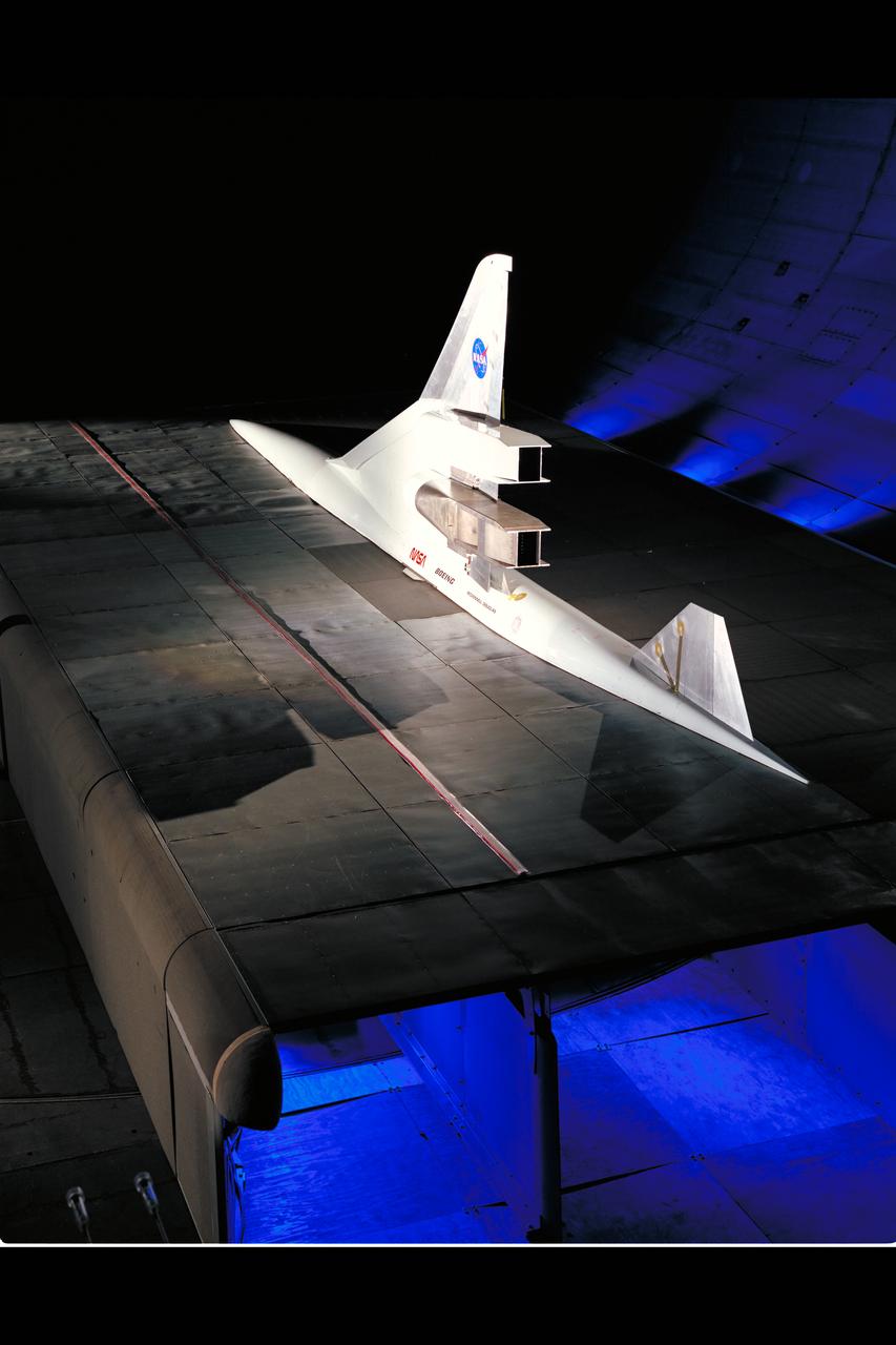
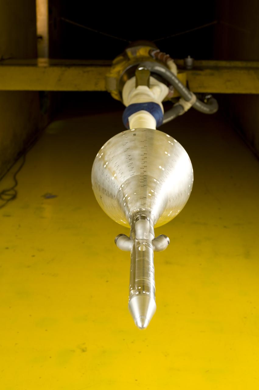
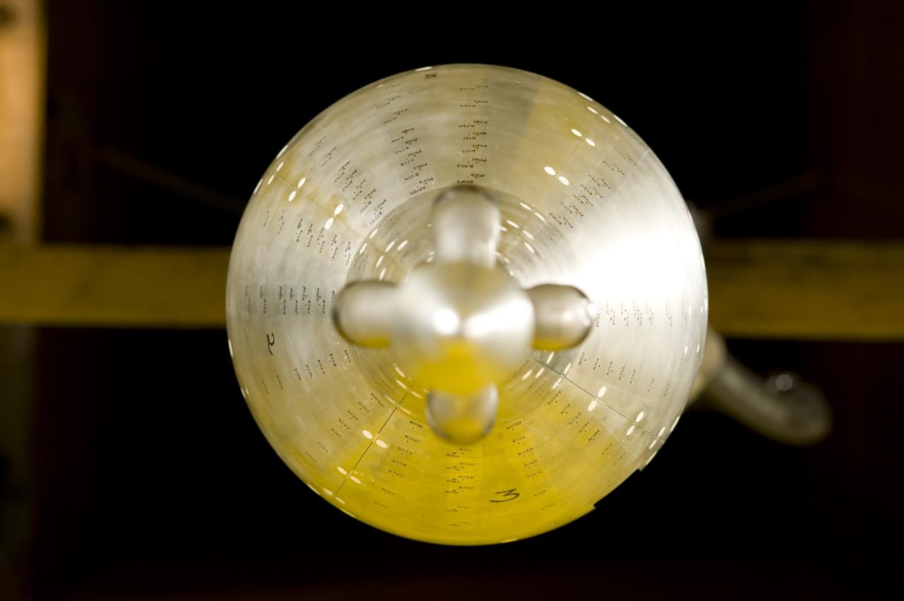
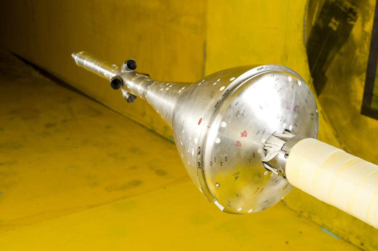
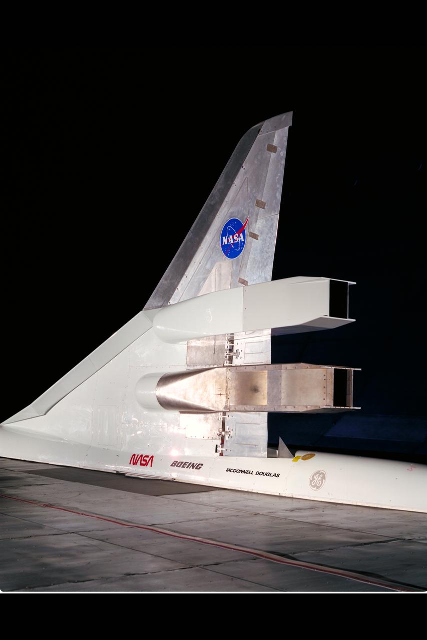
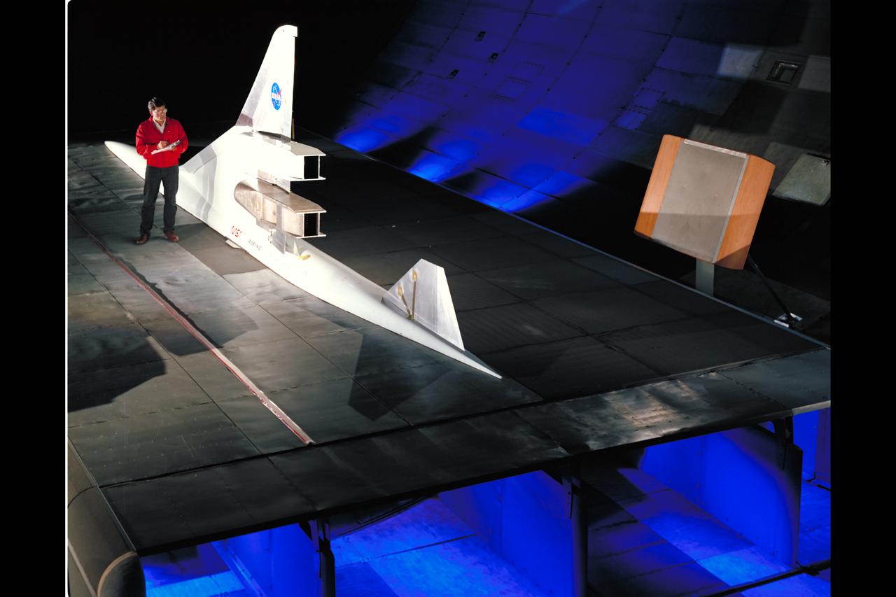
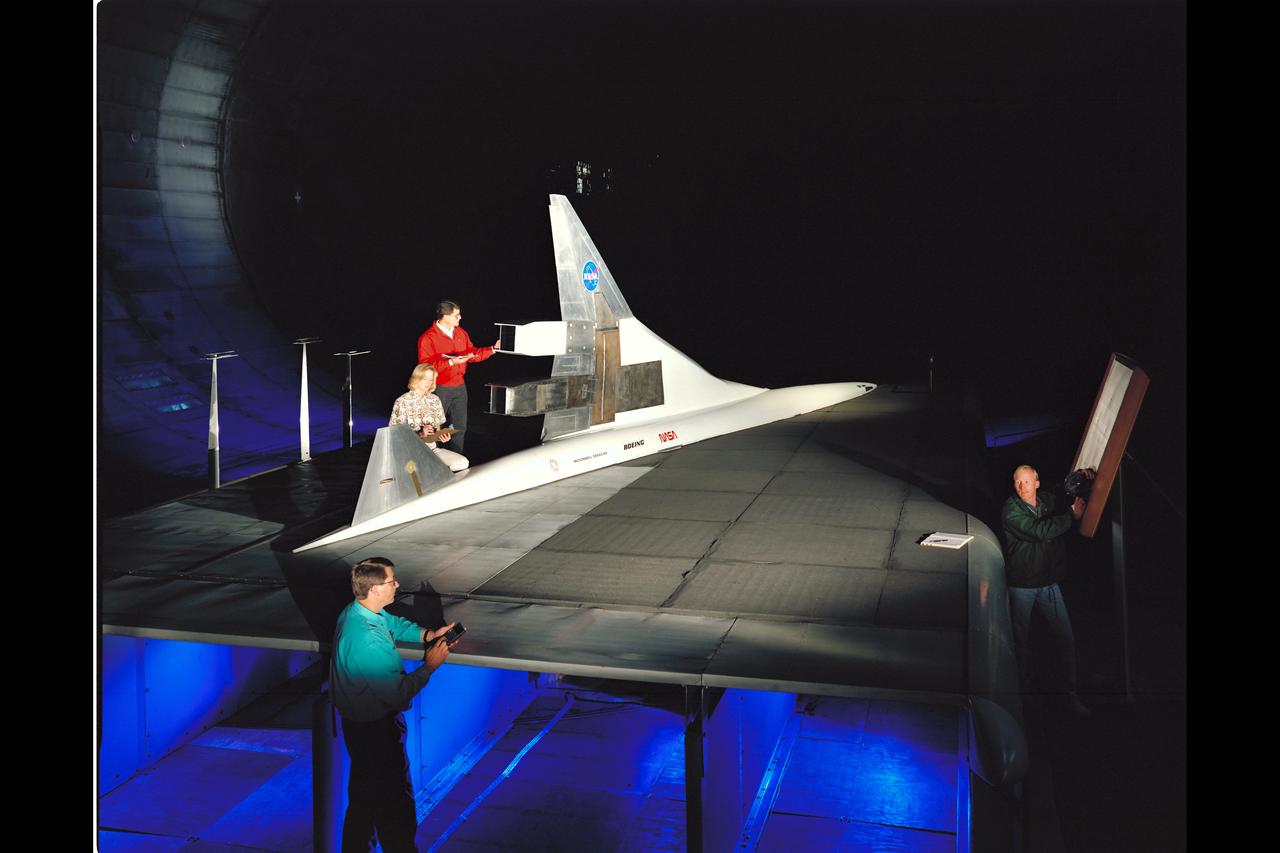
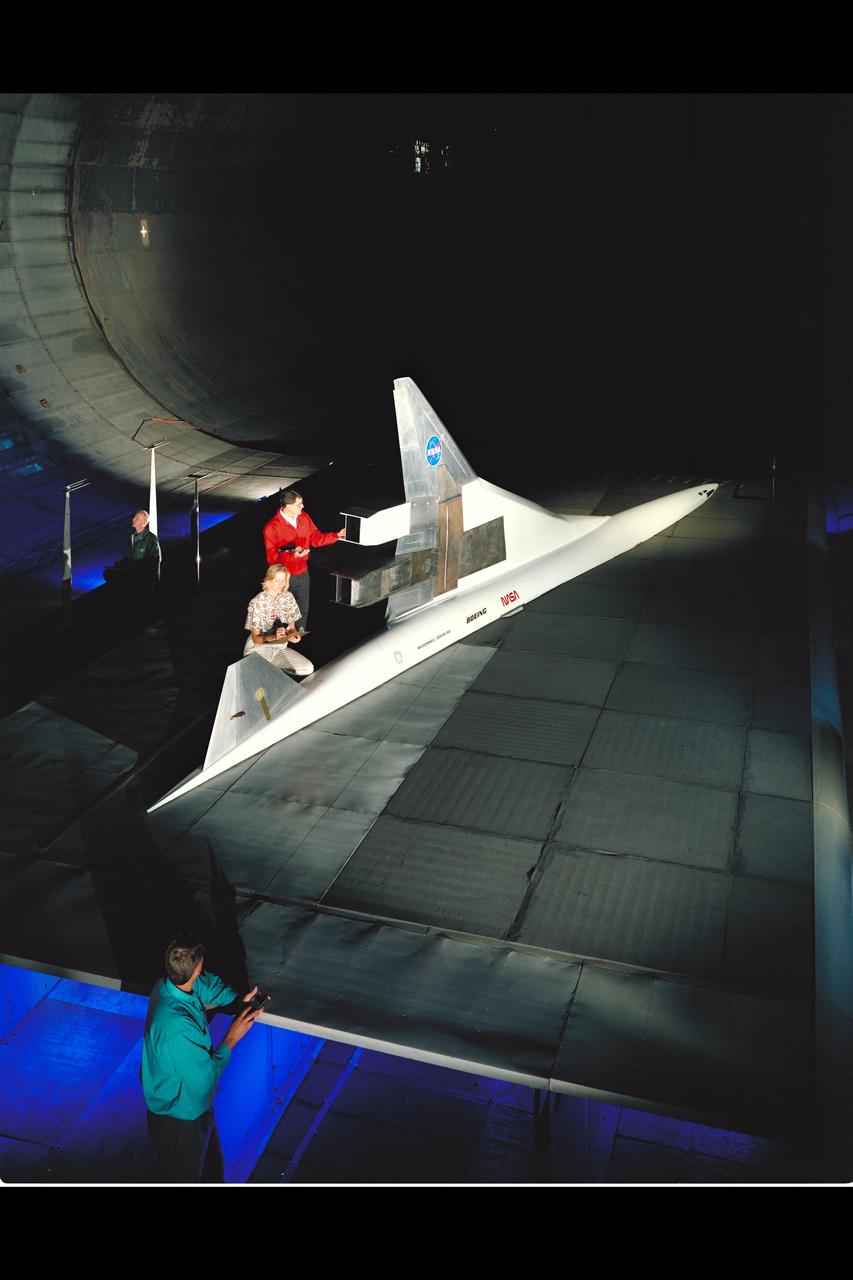
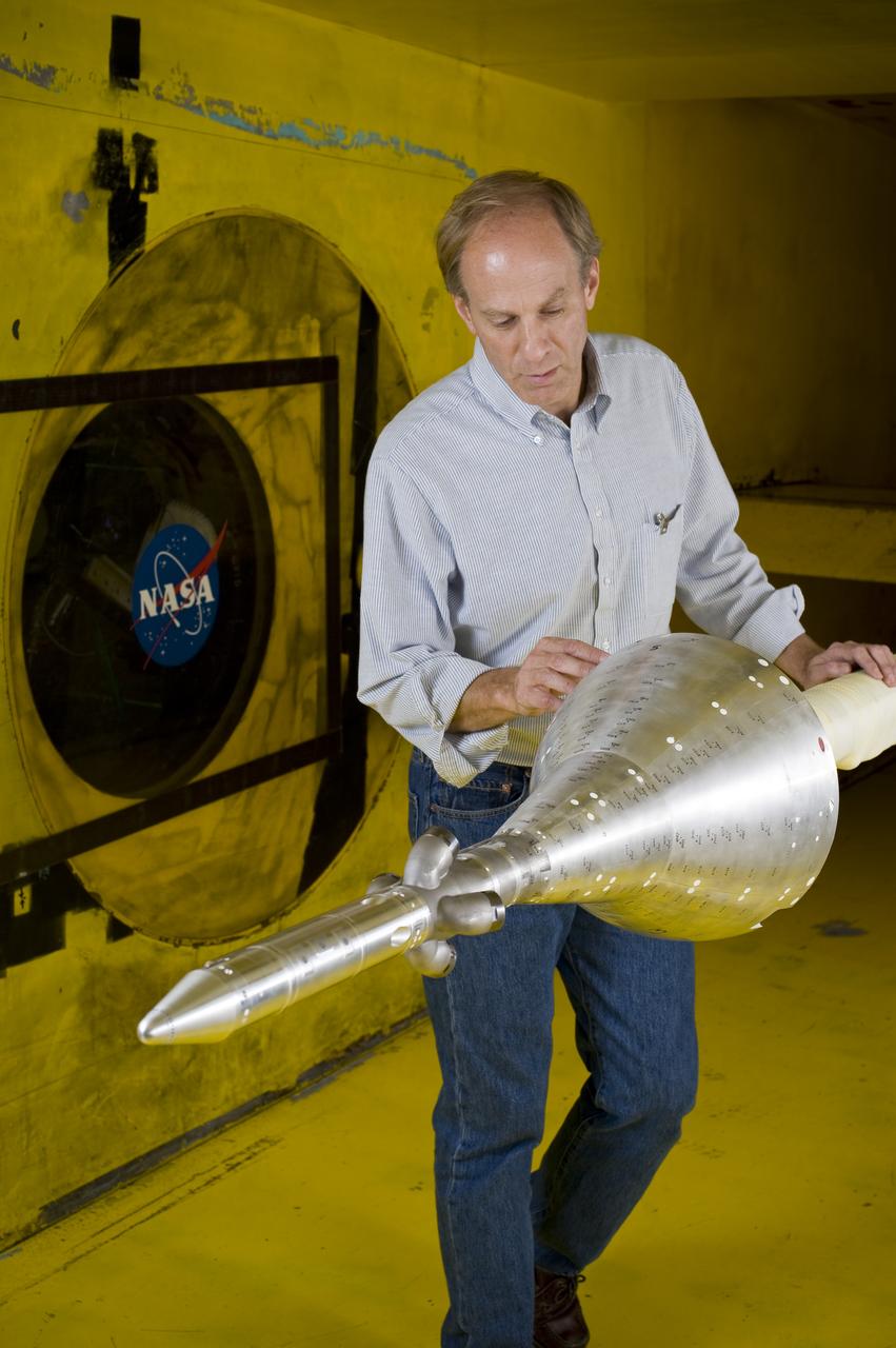
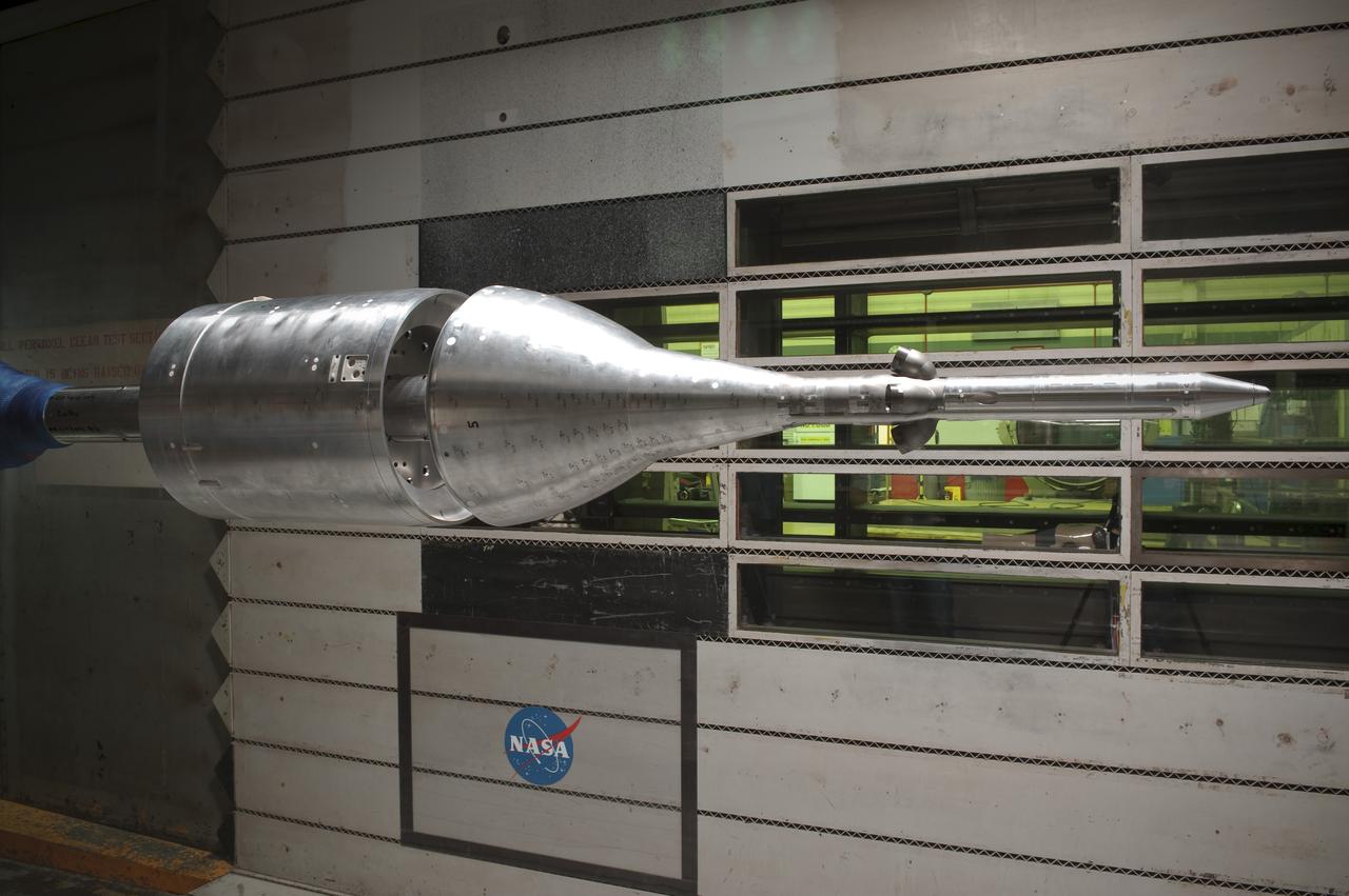
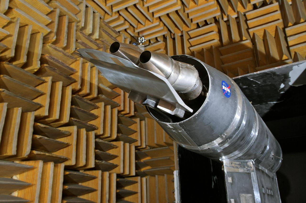
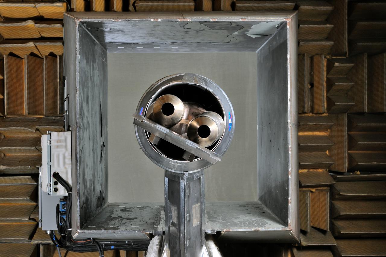
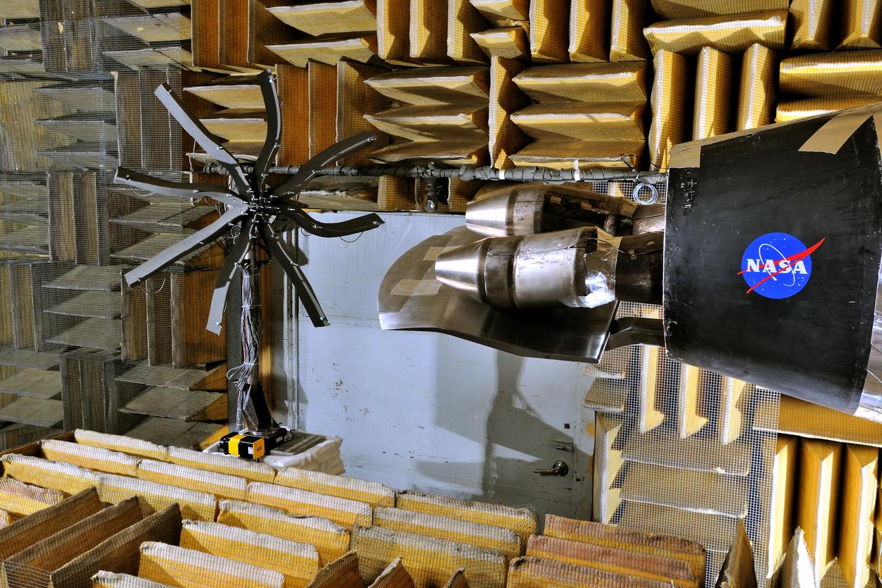
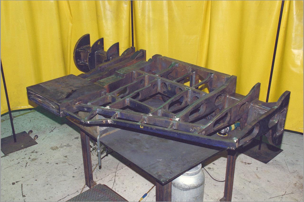
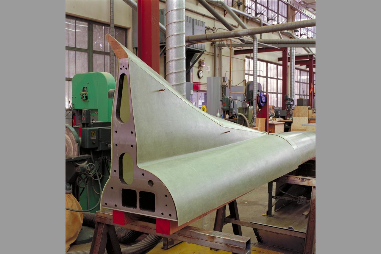
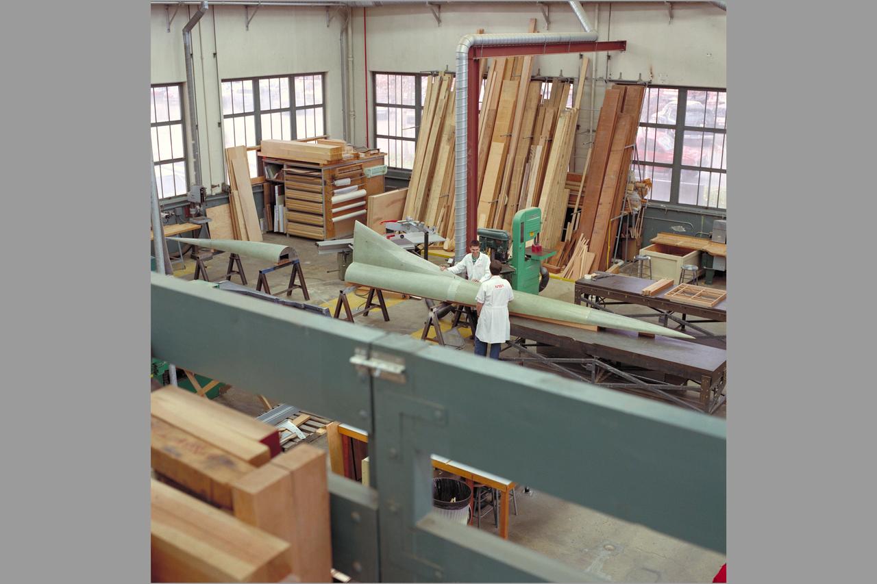
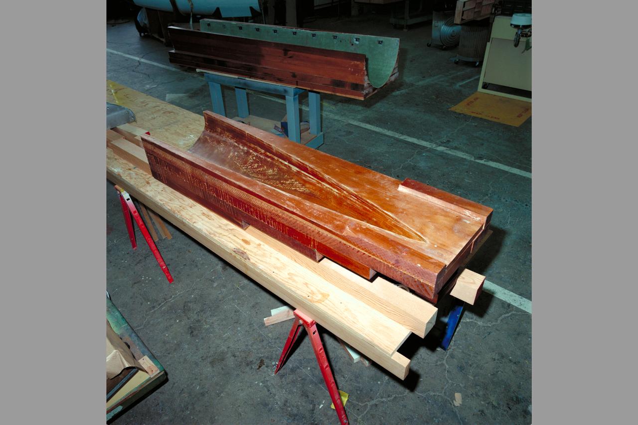
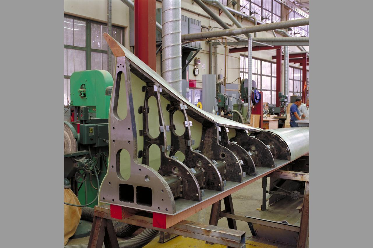
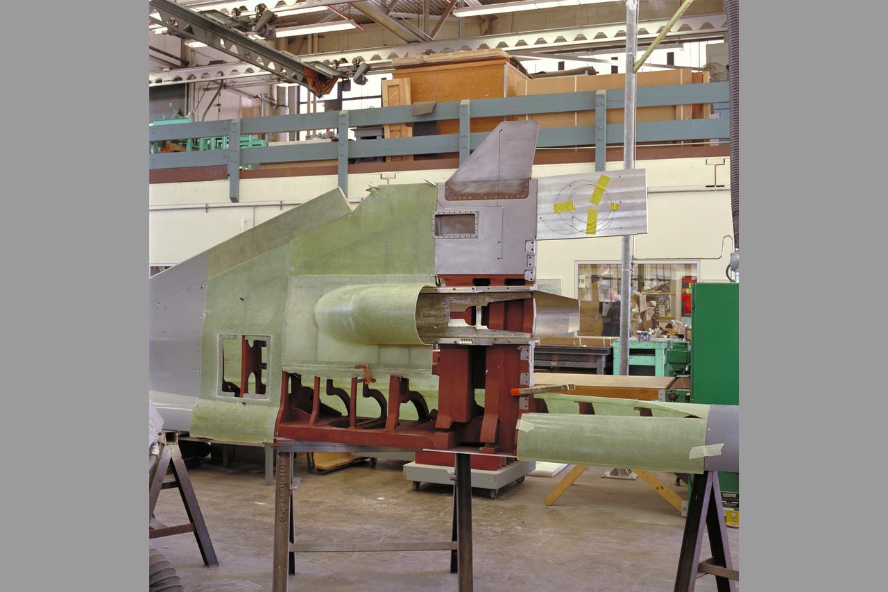
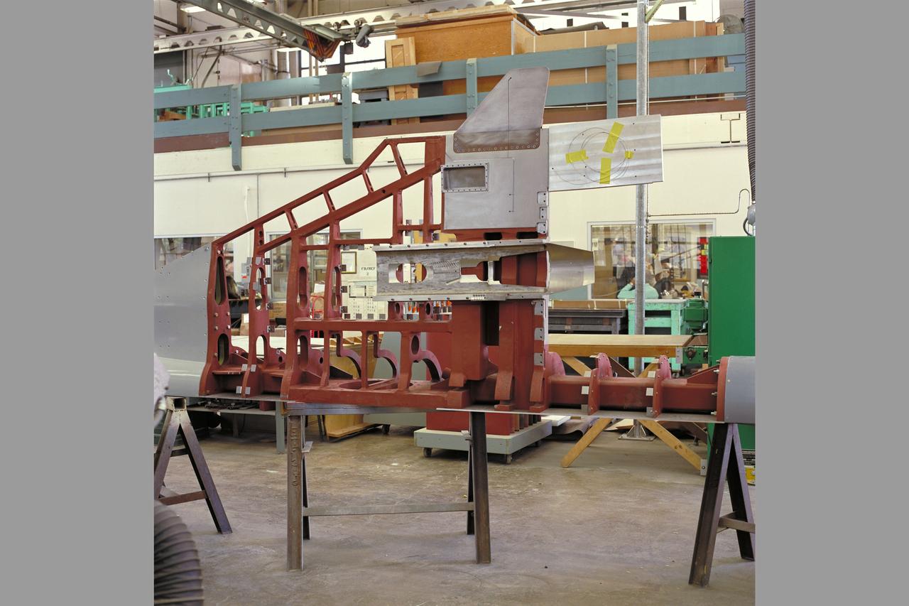
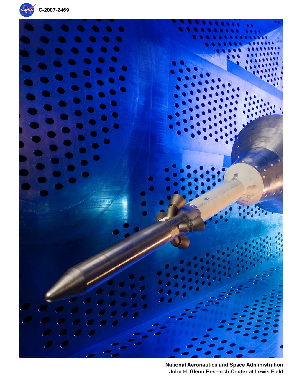
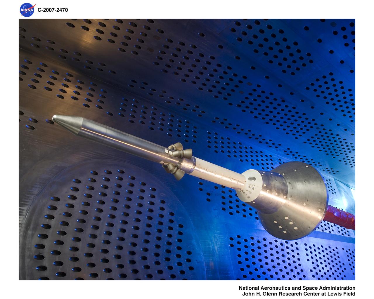
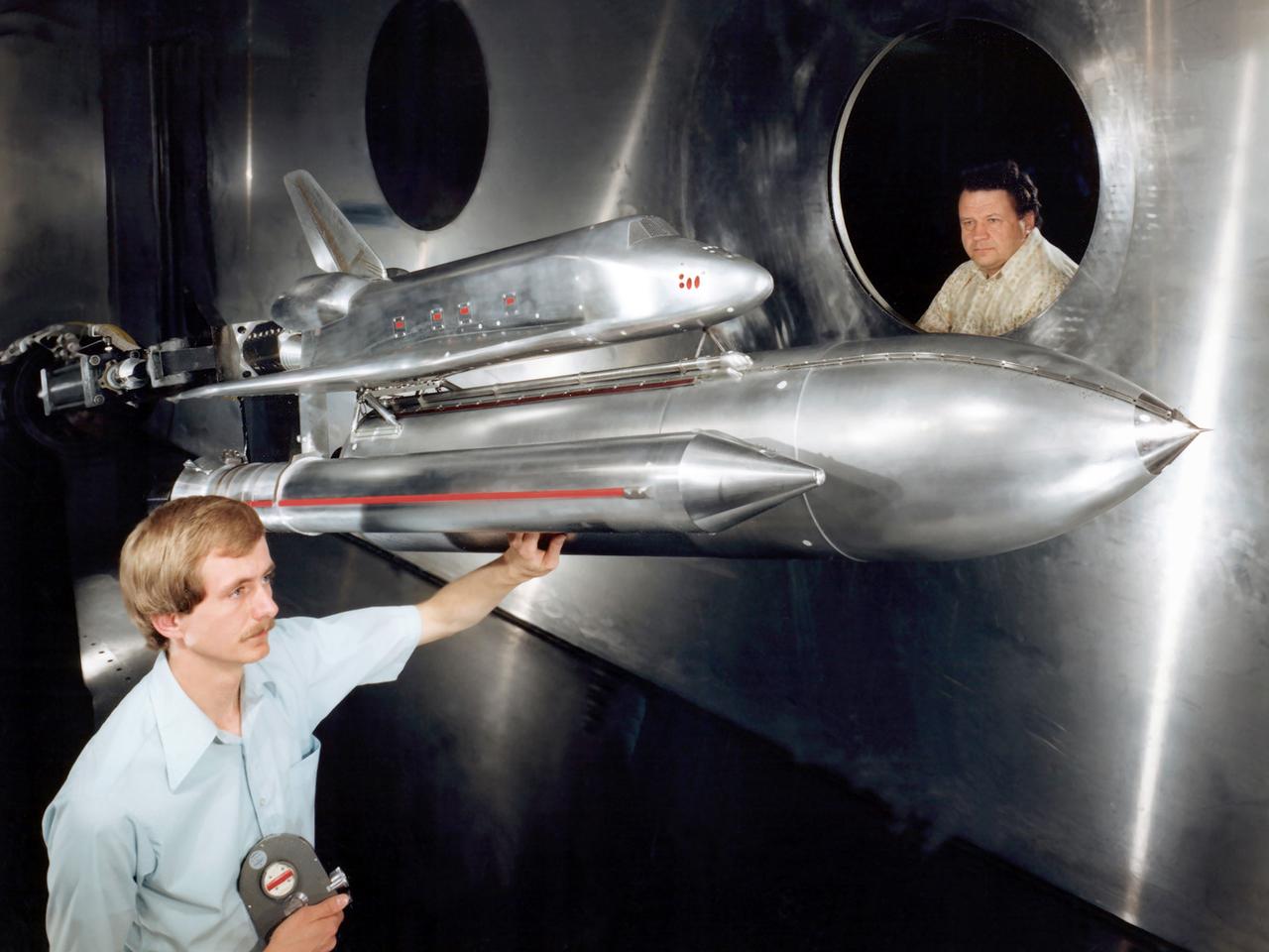
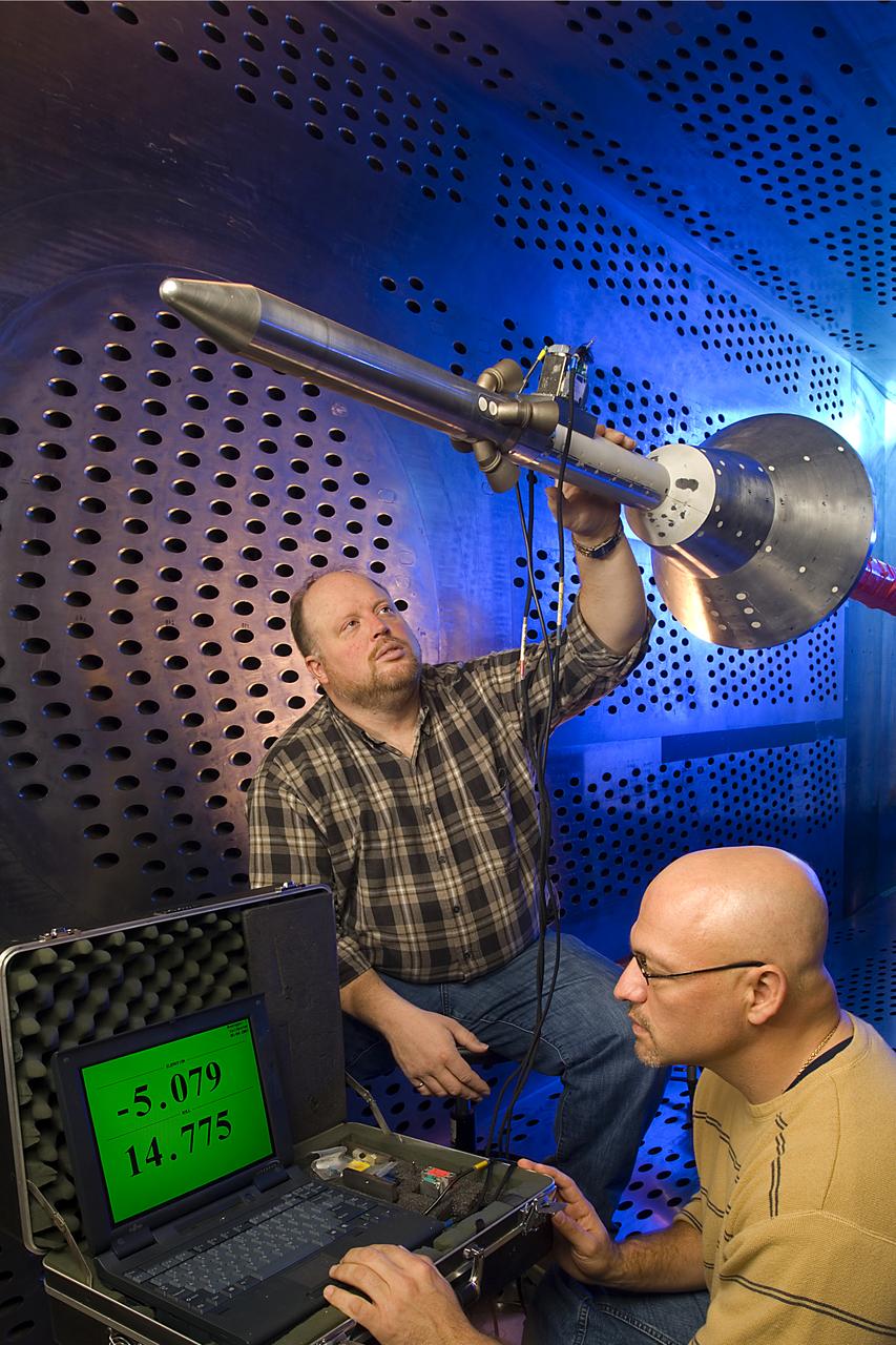
Space Shuttle Pressure Data Model in the 10- by 10-Foot Supersonic Wind Tunnel
Orion Capsule and Launch Abort System (LAS) installed in the NASA Glenn 8x6 Supersonic Wind Tunnel (SWT) for testing. 8x6 supersonic wind tunnel test section with the launch abort system for the Orion capsule
GRC-2007-C-02469
Orion Capsule and Launch Abort System (LAS) installed in the NASA Glenn 8x6 Supersonic Wind Tunnel (SWT) for testing.  This test is an Aero Acoustic test of the LAS. 8x6 supersonic wind tunnel test section
GRC-2007-C-02470
Orion Capsule and Launch Abort System (LAS) installed in the NASA Glenn 8x6 Supersonic Wind Tunnel for testing.  This test is an Aero Acoustic test of the LAS.  Pictured is the calibration of the model's angle of attack
GRC-2007-C-02472
Aero-Acoustic Propulsion Laboratory, AAPL
GRC-2022-C-01318