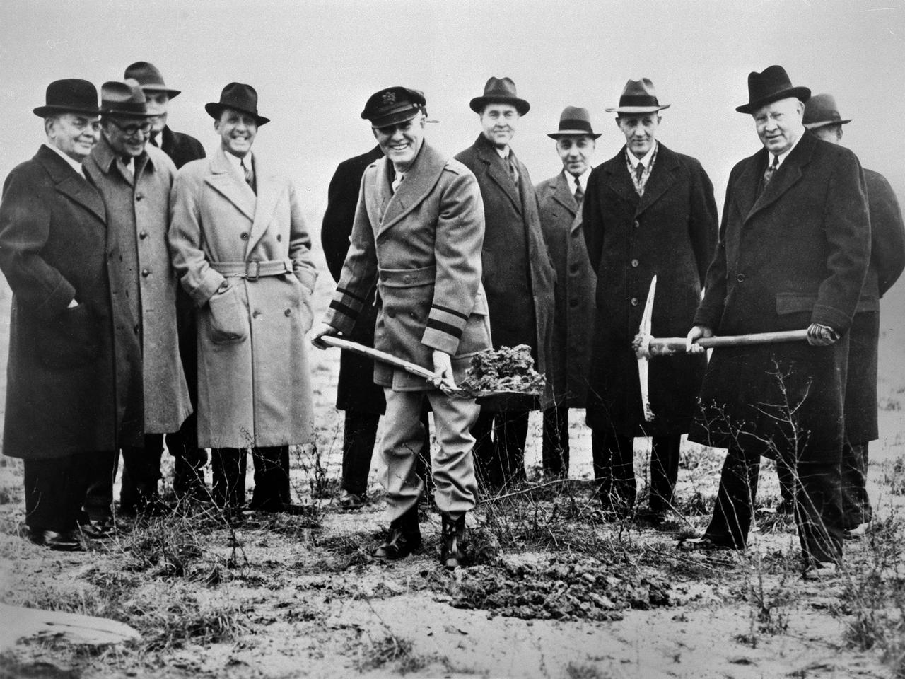
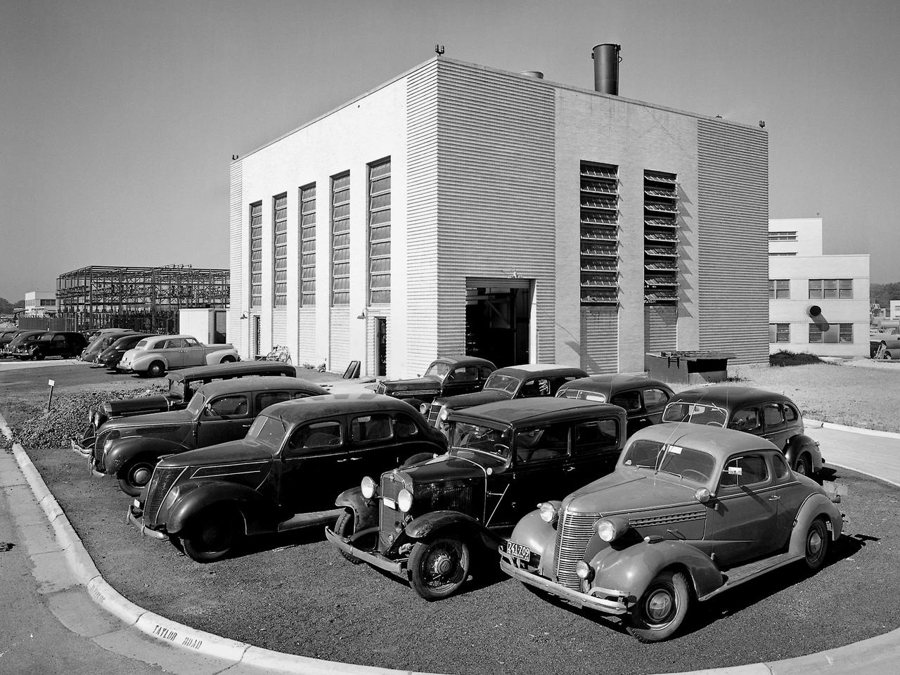
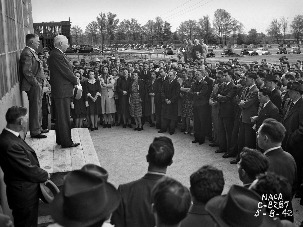
Local politicians and National Advisory Committee for Aeronautics (NACA) officials were on hand for the January 23, 1941 groundbreaking for the NACA’s Aircraft Engine Research Laboratory (AERL). The NACA was established in 1915 to coordinate the nation’s aeronautical research. The committee opened a research laboratory at Langley Field in 1920. By the late 1930s, however, European nations, Germany in particular, were building faster and higher flying aircraft. The NACA decided to expand with a new Ames Aeronautical Laboratory dedicated to high-speed flight and the AERL to handle engine-related research. The NACA examined a number of Midwest locations for its new engine lab before deciding on Cleveland. At the time, Cleveland possessed the nation’s most advanced airport, several key aircraft manufacturing companies, and was home to the National Air Races. Local officials were also able to broker a deal with the power company to discount its electricity rates if the large wind tunnels were operated overnight. The decision was made in October 1940, and the groundbreaking alongside the airport took place on January 23, 1941. From left to right: William Hopkins, John Berry, Ray Sharp, Frederick Crawford, George Brett, Edward Warner, Sydney Kraus, Edward Blythin, and George Lewis
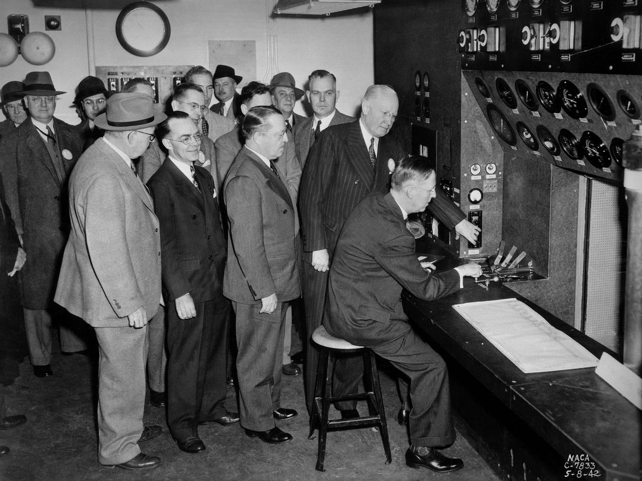
A group of National Advisory Committee for Aeronautics (NACA) officials and local dignitaries were on hand on May 8, 1942, to witness the Initiation of Research at the NACA's new Aircraft Engine Research Laboratory in Cleveland, Ohio. The group in this photograph was in the control room of the laboratory's first test facility, the Engine Propeller Research Building. The NACA press release that day noted, "First actual research activities in what is to be the largest aircraft engine research laboratory in the world was begun today at the National Advisory Committee for Aeronautics laboratory at the Cleveland Municipal Airport.” The ceremony, however, was largely symbolic since most of the laboratory was still under construction. Dr. George W. Lewis, the NACA's Director of Aeronautical Research, and John F. Victory, NACA Secretary, are at the controls in this photograph. Airport Manager John Berry, former City Manager William Hopkins, NACA Assistant Secretary Ed Chamberlain, Langley Engineer-in-Charge Henry Reid, Executive Engineer Carlton Kemper, and Construction Manager Raymond Sharp are also present. The propeller building contained two torque stands to test complete engines at ambient conditions. The facility was primarily used at the time to study engine lubrication and cooling systems for World War II aircraft, which were required to perform at higher altitudes and longer ranges than previous generations.
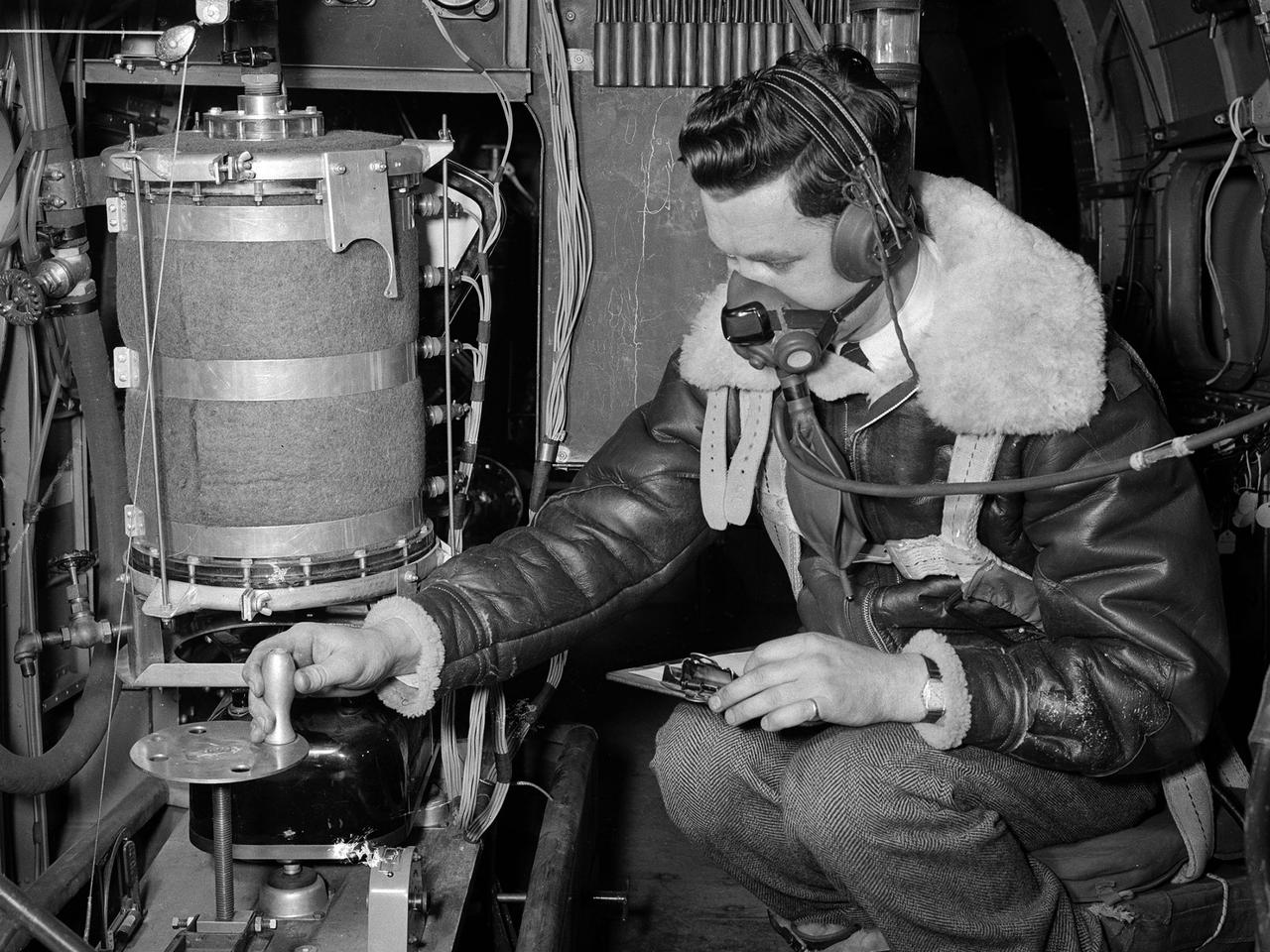
![A researcher at the National Advisory Committee for Aeronautics (NACA) Aircraft Engine Research Laboratory studies the fuel ignition process. Improved fuels and lubrication was an area of particular emphasis at the laboratory during World War II. The military sought to use existing types of piston engines in order to get large numbers of aircraft into the air as quickly as possible. To accomplish its goals, however, the military needed to increase the performance of these engines without having to wait for new models or extensive redesigns. The Aircraft Engine Research Laboratory was called on to lead this effort. The use of superchargers successfully enhanced engine performance, but the resulting heat increased engine knock [fuel detonation] and structural wear. These effects could be offset with improved cooling, lubrication, and fuel mixtures. The NACA researchers in the Fuels and Lubrication Division concentrated on new synthetic fuels, higher octane fuels, and fuel-injection systems. The laboratory studied 16 different types of fuel blends during the war, including extensive investigations of triptane and xylidine.](https://images-assets.nasa.gov/image/GRC-1943-C-02124/GRC-1943-C-02124~medium.jpg)
A researcher at the National Advisory Committee for Aeronautics (NACA) Aircraft Engine Research Laboratory studies the fuel ignition process. Improved fuels and lubrication was an area of particular emphasis at the laboratory during World War II. The military sought to use existing types of piston engines in order to get large numbers of aircraft into the air as quickly as possible. To accomplish its goals, however, the military needed to increase the performance of these engines without having to wait for new models or extensive redesigns. The Aircraft Engine Research Laboratory was called on to lead this effort. The use of superchargers successfully enhanced engine performance, but the resulting heat increased engine knock [fuel detonation] and structural wear. These effects could be offset with improved cooling, lubrication, and fuel mixtures. The NACA researchers in the Fuels and Lubrication Division concentrated on new synthetic fuels, higher octane fuels, and fuel-injection systems. The laboratory studied 16 different types of fuel blends during the war, including extensive investigations of triptane and xylidine.
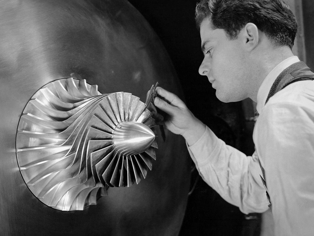
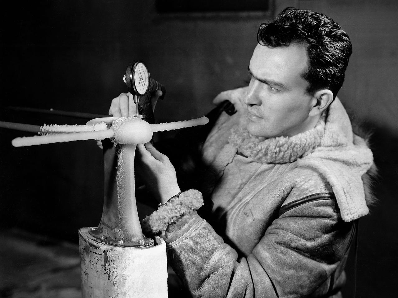
A researcher in the Supercharger Research Division at the National Advisory Committee for Aeronautics (NACA) Aircraft Engine Research Laboratory measures the blade thickness on a supercharger. Superchargers were developed at General Electric used to supply additional air to reciprocating engines. The extra air resulted in increased the engine’s performance, particularly at higher altitudes. The Aircraft Engine Research Laboratory had an entire division dedicated to superchargers during World War II. General Electric developed the supercharger in response to a 1917 request from the NACA to develop a device to enhance high-altitude flying. The supercharger pushed larger volumes of air into the engine manifold. The extra oxygen allowed the engine to operate at its optimal sea-level rating even when at high altitudes. Thus, the aircraft could maintain its climb rate, maneuverability and speed as it rose higher into the sky. NACA work on the supercharger ceased after World War II due to the arrival of the turbojet engine. The Supercharger Research Division was disbanded in October 1945 and reconstituted as the Compressor and Turbine Division.
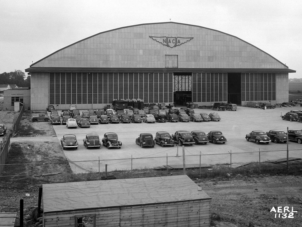
The Flight Research Building at the National Advisory Committee for Aeronautics (NACA) Aircraft Engine Research Laboratory is a 272- by 150-foot hangar with an internal height up to 90 feet. The hangar’s massive 37.5-foot-tall and 250-foot-long doors can be opened in sections to suit different size aircraft. The hangar has sheltered a diverse fleet of aircraft over the decades. These have ranged from World War II bombers to Cessna trainers and from supersonic fighter jets to a DC–9 airliner. At the time of this September 1942 photograph, however, the hangar was being used as an office building during the construction of the laboratory. In December of 1941, the Flight Research Building became the lab’s first functional building. Temporary offices were built inside the structure to house the staff while the other buildings were completed. The hangar offices were used for an entire year before being removed in early 1943. It was only then that the laboratory acquired its first aircraft, pilots and flight mechanics. The temporary one-story offices can be seen in this photograph inside the large sliding doors. Also note the vertical lift gate below the NACA logo. The gate was installed so that the tails of larger aircraft could pass into the hangar. The white Farm House that served as the Administration Building during construction can be seen in the distance to the left of the hangar.
The Steam Plant at the National Advisory Committee for Aeronautics (NACA) Aircraft Engine Research Laboratory supplies steam to the major test facilities and office buildings. Steam is used for the Icing Research Tunnel's spray system and the Engine Research Building’s desiccant air dryers. In addition, its five boilers supply heat to various buildings and the cafeteria. Schirmer-Schneider Company built the $141,000 facility in the fall of 1942, and it has been in operation ever since.
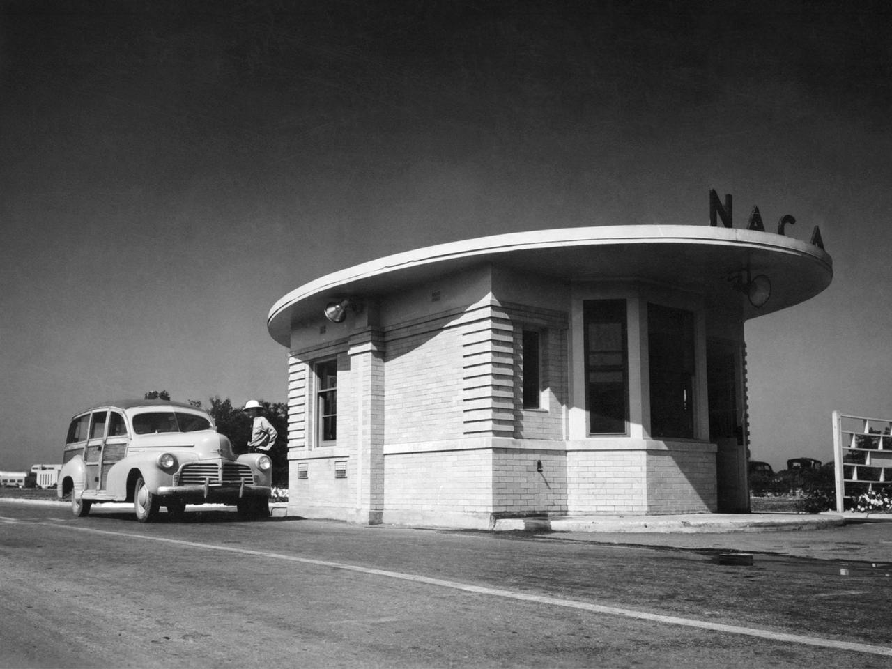
A vehicle leaves the National Advisory Committee for Aeronautics (NACA) Aircraft Engine Research Laboratory on August 14, 1945. At 7 p.m. that evening President Truman announced that Japan had accepted terms for surrender and World War II was over. The end of the war brought significant changes for the laboratory. The NACA would cease its troubleshooting of military aircraft and return to research. Researchers would increase their efforts to address the new technologies that emerged during the war. The entire laboratory was reorganized in October to better investigate turbojets, ramjets, and rockets. The guard house sat on the main entrance to the laboratory off of Brookpark Road. The building was fairly small and easily crowded. In the early 1960s a new security facility was built several hundred feet beyond the original guard house. The original structure remained in place for several years but was not utilized. The subsequent structure was replaced in 2011 by a new building and entrance configuration.
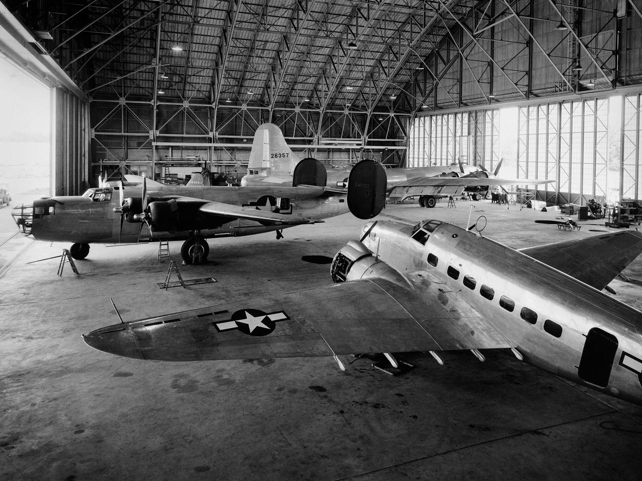
A Consolidated B–24D Liberator (left), Boeing B–29 Superfortress (background), and Lockheed RA–29 Hudson (foreground) parked inside the Flight Research Building at the National Advisory Committee for Aeronautics (NACA) Aircraft Engine Research Laboratory in Cleveland, Ohio. A P–47G Thunderbolt and P–63A King Cobra are visible in the background. The laboratory utilized 15 different aircraft during the final 2.5 years of World War II. This starkly contrasts with the limited-quantity, but long-duration aircraft of the NASA’s modern fleet. The Flight Research Building is a 272- by 150-foot hangar with an internal height ranging from 40 feet at the sides to 90 feet at its apex. The steel support trusses were pin-connected at the top with tension members extending along the corrugated transite walls down to the floor. The 37.5-foot-tall and 250-foot-long doors on either side can be opened in sections. The hangar included a shop area and stock room along the far wall, and a single-story office wing with nine offices, behind the camera. The offices were later expanded. The hangar has been in continual use since its completion in December 1942. Nearly 70 different aircraft have been sheltered here over the years. Temporary offices were twice constructed over half of the floor area when office space was at a premium.
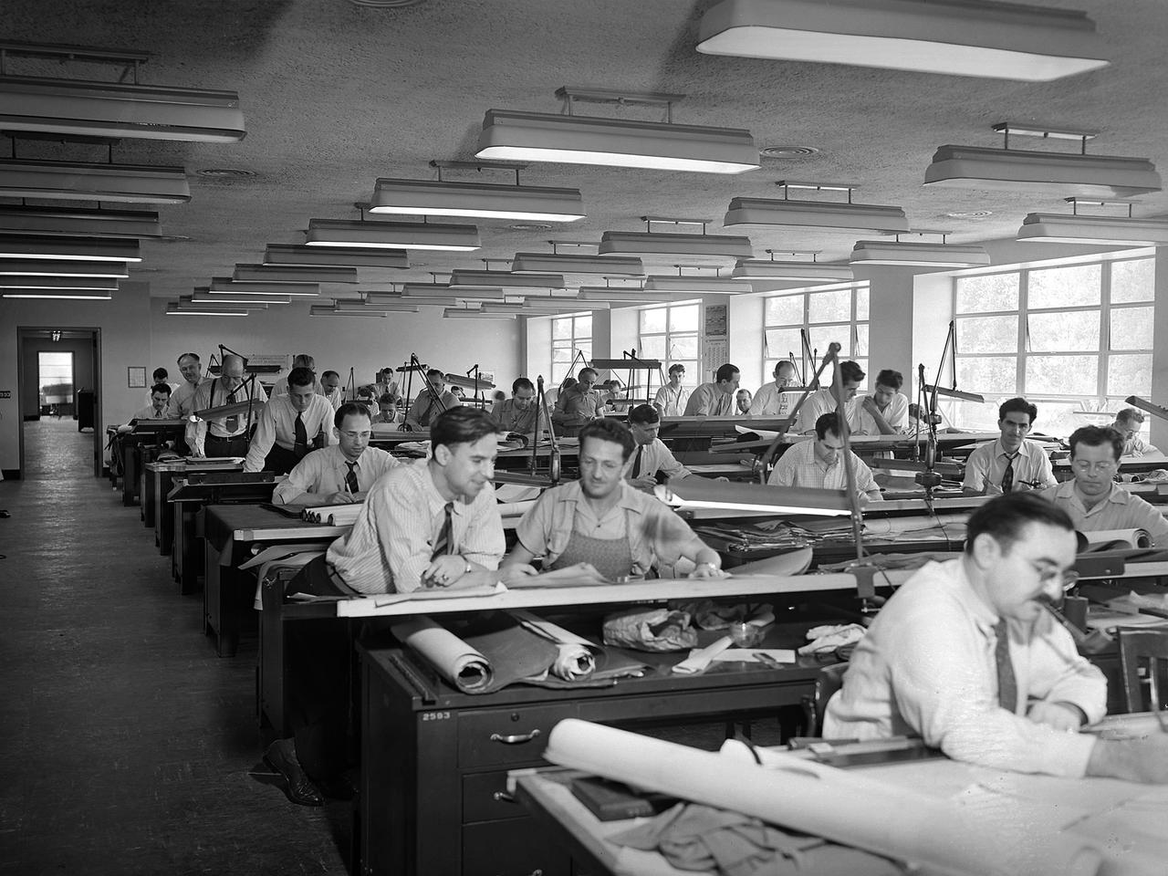
The National Advisory Committee for Aeronautics (NACA) Aircraft Engine Research Laboratory was designed by a group of engineers at the Langley Memorial Aeronautical Laboratory in late 1940 and 1941. Under the guidance of Ernest Whitney, the men worked on drawings and calculations in a room above Langley’s Structural Research Laboratory. The main Aircraft Engine Research Laboratory design group originally consisted of approximately 30 engineers and draftsmen, but there were smaller groups working separately on specific facilities. The new engine lab would have six principal buildings: the Engine Research Building, hangar, Fuels and Lubricants Building, Administration Building, Propeller Test Stand, and Altitude Wind Tunnel. In December 1941 most of those working on the project transferred to Cleveland from Langley. Harrison Underwood and Charles Egan led 18 architectural, 26 machine equipment, 3 structural and 10 mechanical draftsmen. Initially these staff members were housed in temporary offices in the hangar. As sections of the four-acre Engine Research Building were completed in the summer of 1942, the design team began relocating there. The Engine Research Building contained a variety of test cells and laboratories to address virtually every aspect of piston engine research. It also contained a two-story office wing, seen in this photograph that would later house many of the powerplant research engineers.
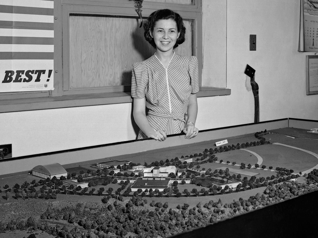
Zella Morewitz poses with a model of the National Advisory Committee for Aeronautics (NACA) Aircraft Engine Research Laboratory, currently the NASA Glenn Research Center. The model was displayed in the Administration Building during the construction of the laboratory in the early 1940s. Detailed models of the individual test facilities were also fabricated and displayed in the facilities. The laboratory was built on a wedge of land between the Cleveland Municipal Airport on the far side and the deep curving valley etched by the Rocky River on the near end. Roughly only a third of the laboratory's semicircle footprint was initially utilized. Additional facilities were added to the remaining areas in the years after World War II. In the late 1950s the site was supplemented by the acquisition of additional adjacent land. Morewitz joined the NACA in 1935 as a secretary in the main office at the Langley Memorial Aeronautical Laboratory. In September 1940 she took on the task of setting up and guiding an office dedicated to the design of the NACA’s new engine research laboratory. Morewitz and the others in the design office transferred to Cleveland in December 1941 to expedite the construction. Morewitz served as Manager Ray Sharp’s secretary for six years and was a popular figure at the new laboratory. In December 1947 Morewitz announced her engagement to Langley researcher Sidney Batterson and moved back to Virginia.
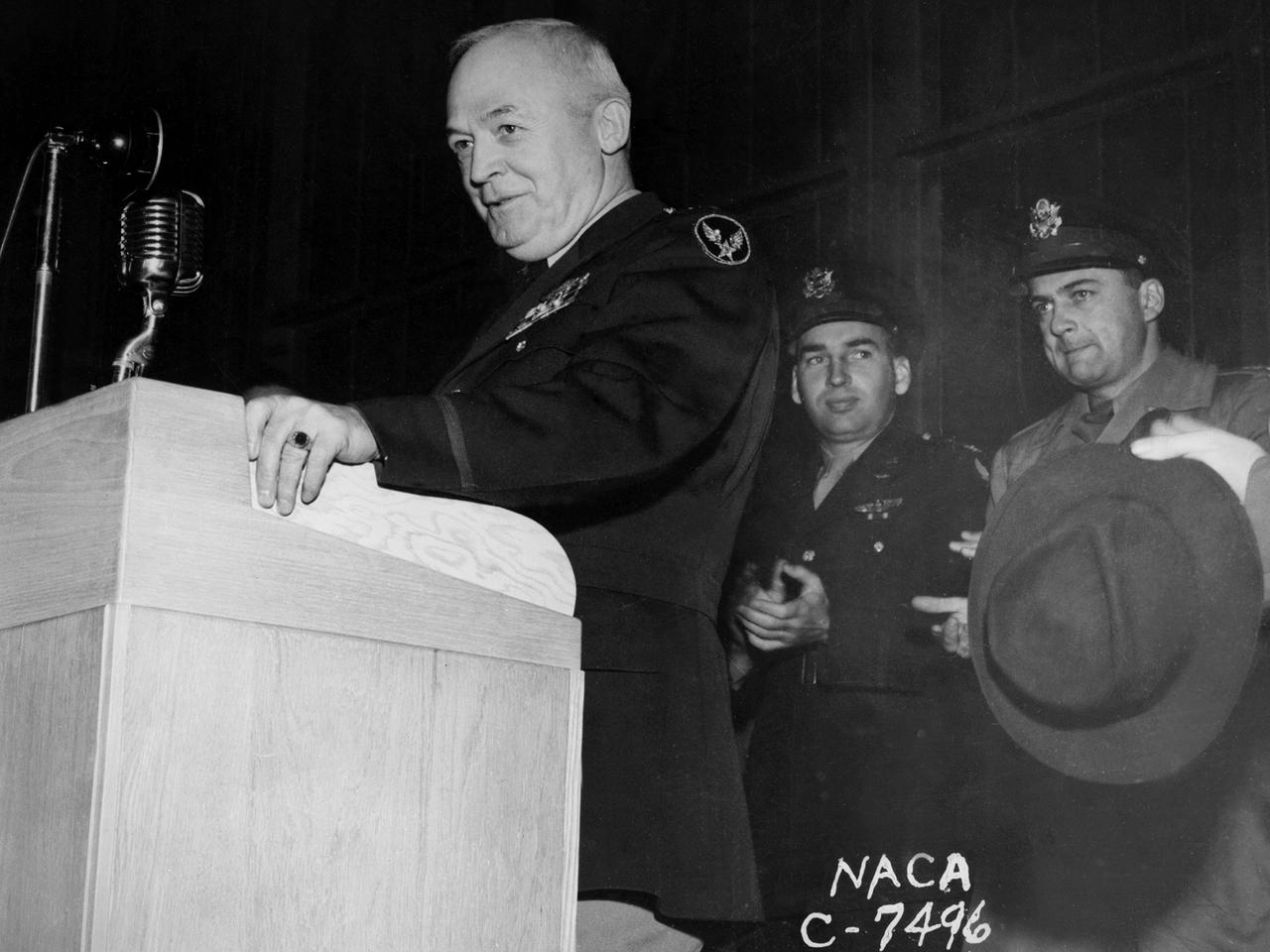
General Henry “Hap” Arnold, Commander of the US Army Air Forces during World War II, addresses the staff at the National Advisory Committee for Aeronautics (NACA) Aircraft Engine Research Laboratory on November 9, 1944. Arnold told the employees assembled in the hangar, “You’ve got a dual task. You’ve got a job ahead of you to keep the army and the navy air forces equipped with the finest equipment that you can for this war. You also have the job of looking forward into the future and starting now those developments, those experiments, that are going to keep us in our present situation—ahead of the world in the air. And that is quite a large order, and I leave it right in your laps.” Arnold served on the NACA’s Executive Committee in Washington from 1938 to 1944 and had been a strong advocate for the creation of the new engine research facility in Cleveland. Arnold believed in continual research and development. He pressed the nation’s aviation leaders to pursue the new jet engine technology, while simultaneously pushing to increase the performance of the nation’s largest piston engine for the B–29 Superfortress program. The general’s hectic wartime agenda limited his visit to the Cleveland laboratory to just a few hours, but he toured several of the NACA’s new test facilities including the Static Jet Propulsion Laboratory, the Icing Research Tunnel, and a B–24 Liberator in the hangar.
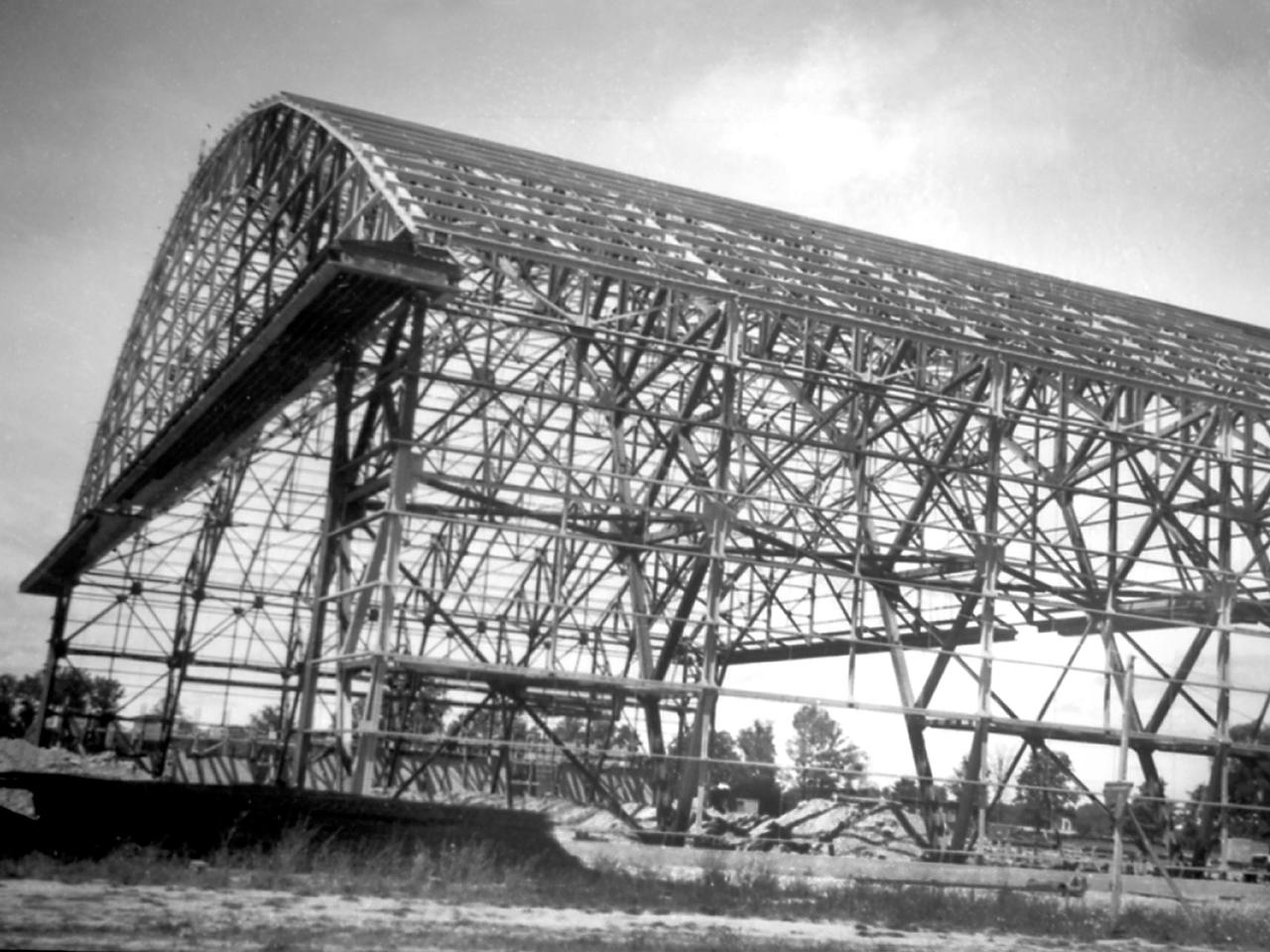
Northward view of the Flight Research Building's steel framework in August 1941 as it neared completion at the National Advisory Committee for Aeronautics (NACA) Aircraft Engine Research Laboratory. The 272- by 150-foot hangar had a 90-foot clearance at its highest point. The hangar was the first structure built and was needed as a shelter for the growing staff, who occupied a nearby Farm House at this point. In January 1941 the Cleveland-area R.P. Carbone Construction Company was selected to build the hangar. Over the ensuing months, however, the NACA management became frustrated by the slow progress on the project. Although Carbone was contracted to complete the entire hangar by August, it was September before even the structural steel frame, seen in this photograph, was in place. Officials estimated the roof and siding were four months behind schedule. This was a serious concern because the lab’s research, support and administrative staff members would soon begin arriving. By mid-September the transite walls began enclosing the skeleton. In October work began on the temporary offices inside. The building was completed in mid-December just in time for the staff arriving from Langley.
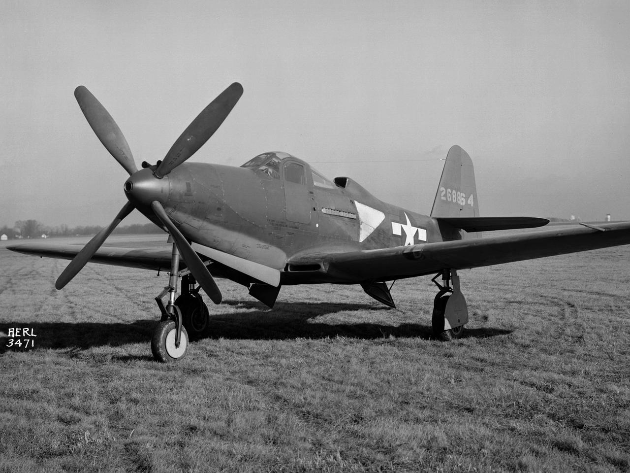
The Army Air Forces lent the National Advisory Committee for Aeronautics (NACA) Aircraft Engine Research Laboratory a Bell P–63A King Cobra in October 1943 to complement the lab's extensive efforts to improve the Allison V–1710 engine. The V–1710-powered P–63A was a single-seat fighter that could reach speeds of 410 miles per hour and an altitude of 43,000 feet. The fighter, first produced in 1942, was an improvement on Bell’s P–39, but persistent performance problems at high altitudes prevented its acceptance by the Air Corps. Instead many of the P–63s were transferred to the Soviet Union. Almost every test facility at the NACA’s engine lab was used to study the Allison V–1710 engine and its supercharger during World War II. Researchers were able to improve the efficiency, capacity and pressure ratio of the supercharger. They found that improved cooling significantly reduced engine knock in the fuel. Once the researchers were satisfied with their improvements, the new supercharger and cooling components were installed on the P–63A. The Flight Research Division first established the aircraft’s normal flight performance parameters such as speed at various altitudes, rate of climb, and peak altitude. Ensuing flights established the performance parameters of the new configuration in order to determine the improved performance. The program increased V–1710’s horsepower from 1650 to 2250.
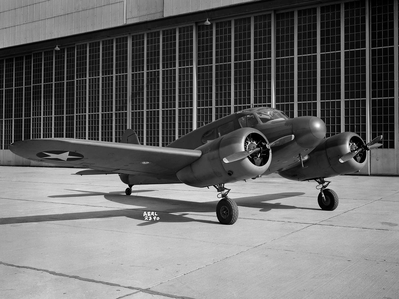
The Aircraft Engine Research Laboratory acquired the five-seat Cessna UC–78 in March 1943 to maintain the proficiency of its pilots. The UC–78 was referred to as the “Bamboo Bomber” because of its wooden wings and tail and its fabric-covered steel body. The aircraft was produced in 1939 for civilian use, but the military soon began ordering them as training aircraft. The military also began using the aircraft for personnel transport. Cessna produced over 4600 of the aircraft for the military during World War II. The National Advisory Committee for Aeronautics’ (NACA) pilot Howard Lilly flew the UC–78 extensively during its residency in Cleveland. The aircraft was used for ferrying staff members to nearby locations and helping the pilots keep their flying hours up. The UC–78 was transferred in October 1945.
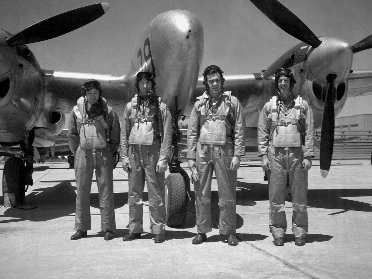
The Aircraft Engine Research Laboratory’s pilot corps during the final days of World War II: from left to right, Joseph Vensel, Howard Lilly, William Swann, and Joseph Walker. William “Eb” Gough joined the group months after this photograph. These men were responsible for flying the various National Advisory Committee for Aeronautics (NACA) aircraft to test new engine modifications, study ice buildup, and determine fuel performance. Vensel, a veteran pilot from Langley, was the Chief of Flight Operations and a voice of reason at the laboratory. In April 1947 Vensel was transferred to lead the new Muroc Flight Tests Unit in California until 1966. Lilly was a young pilot with recent Navy experience. Lilly also flew in the 1946 National Air Races. He followed Vensel to Muroc in July 1947 where he became the first NACA pilot to penetrate the sound barrier. On May 3, 1948, Lilly became the first NACA pilot to die in the line of duty. Swann was a young civilian pilot when he joined the NACA. He spent his entire career at the Cleveland laboratory, and led the flight operations group from the early 1960s until 1979. Two World War II veterans joined the crew after the war. Walker was a 24-year-old P–38 reconnaissance pilot. He joined the NACA as a physicist in early 1945 but soon worked his way into the cadre of pilots. Walker later gained fame as an X-plane pilot at Muroc and was killed in a June 1966 fatal crash. Gough survived being shot down twice during the war and was decorated for flying rescue missions in occupied areas.
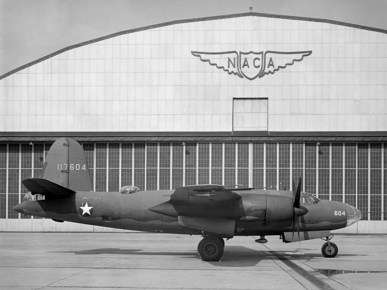
The Aircraft Engine Research Laboratory’s first aircraft, a Martin B–26B Marauder, parked in front of the Flight Research Building in September 1943. The military loaned the B–26B to the National Advisory Committee for Aeronautics (NACA) to augment the lab’s studies of the Wright Aeronautical R–2800 engines. The military wanted to improve the engine cooling in order to increase the bomber’s performance. On March 17, 1943, the B–26B performed the very first research flight at the NACA’s new engine laboratory. The B–26B received its “Widowmaker” nickname during the rushed effort to transition the new aircraft from design to production and into the sky. During World War II, however, the B–26B proved itself to be a capable war machine. The U.S. lost fewer Marauders than any other type of bomber employed in the war. The B–26B was originally utilized at low altitudes in the Pacific but had its most success at high altitudes over Europe. The B–26B’s flight tests in Cleveland during 1943 mapped the R-2800 engine’s behavior at different altitudes and speeds. The researchers were then able to correlate engine performance in ground facilities to expected performance at different altitudes. They found that air speed, cowl flap position, angle of attack, propeller thrust, and propeller speed influenced inlet pressure recovery and exhaust distribution. The flight testing proceeded quickly, and the B–26B was transferred elsewhere in October 1943.
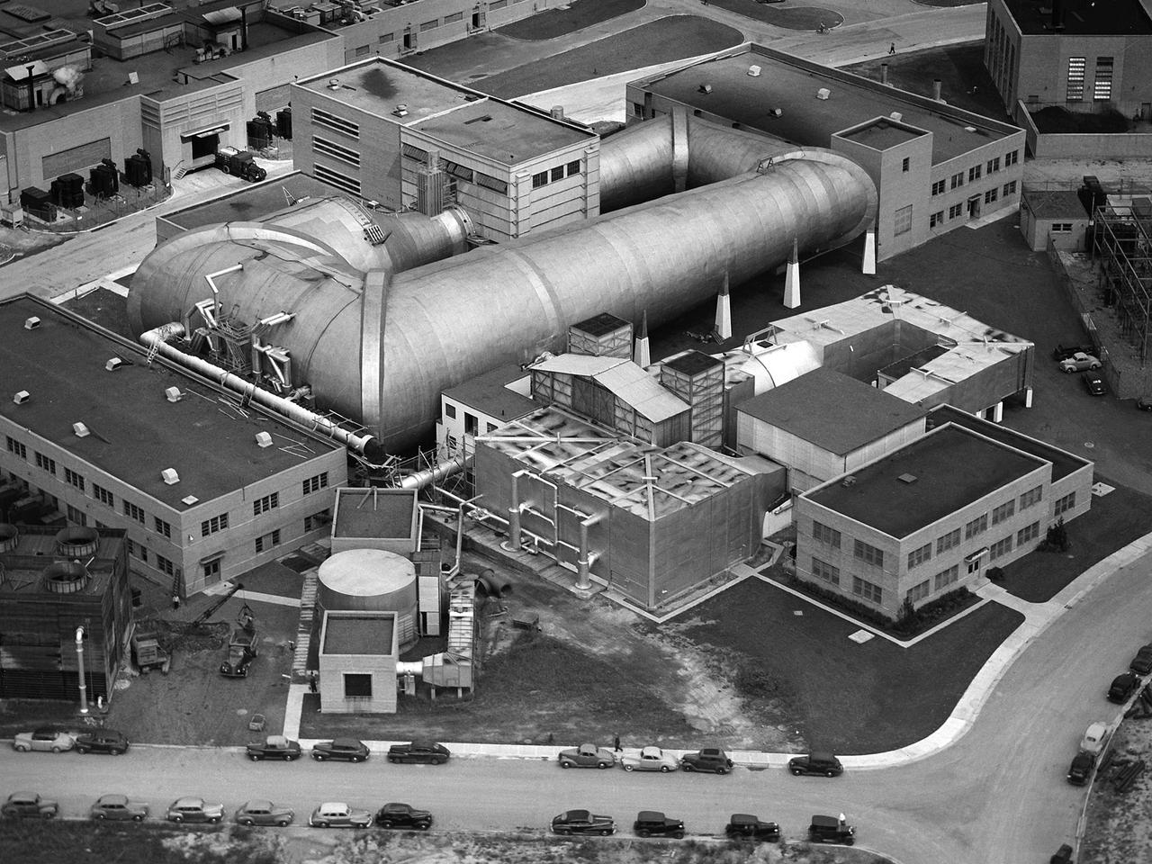
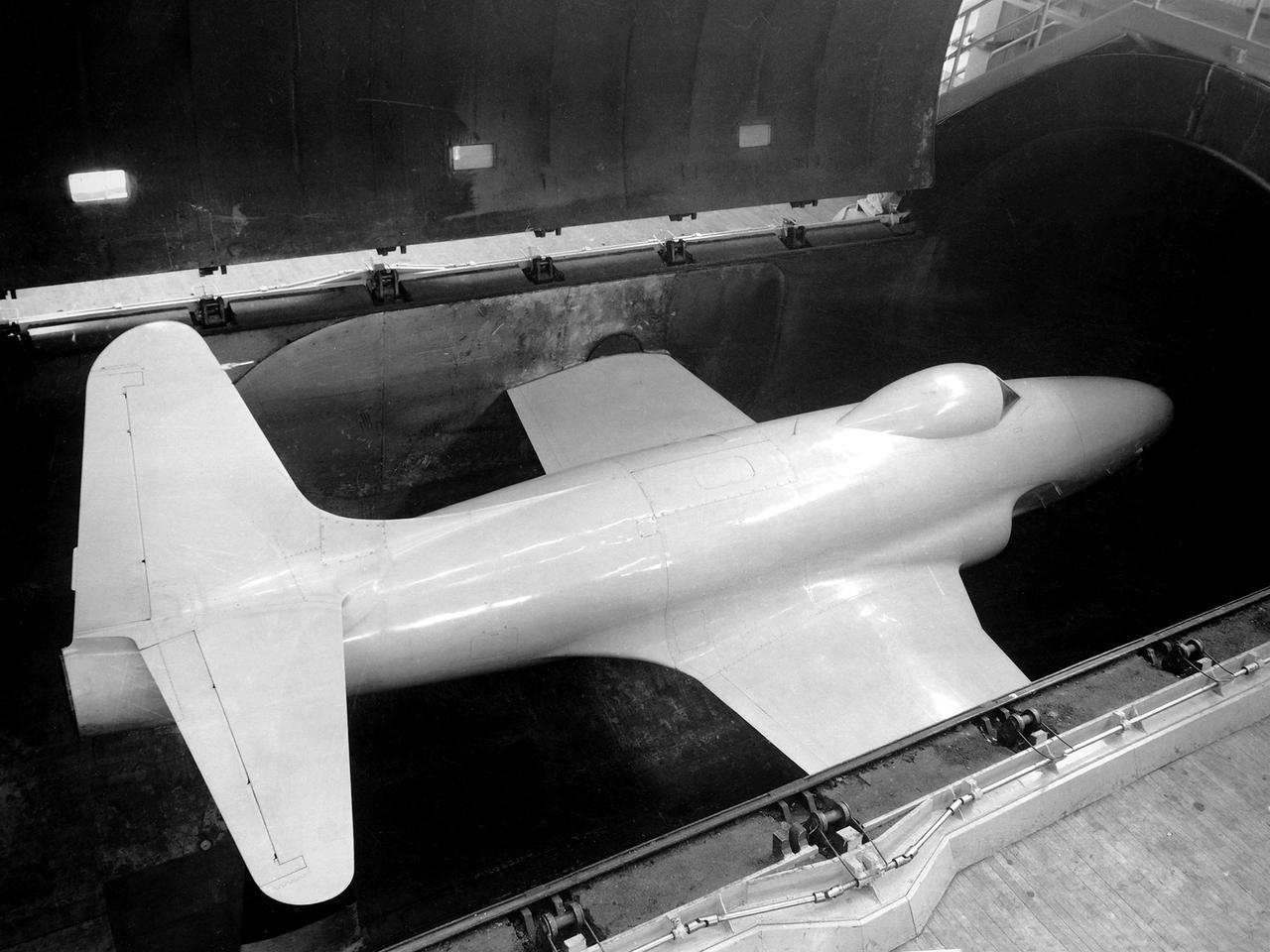
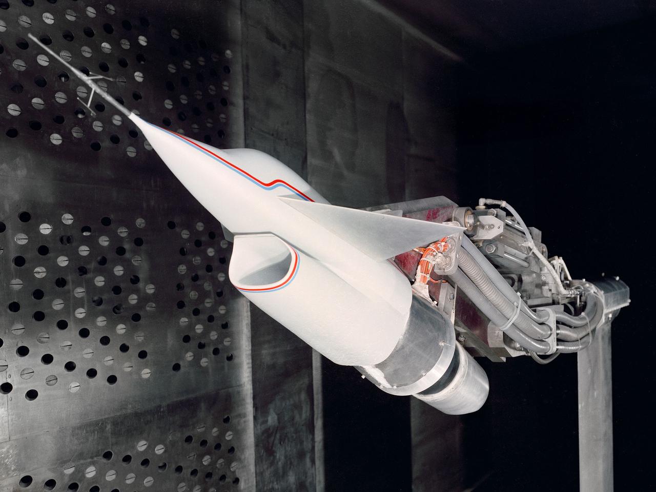
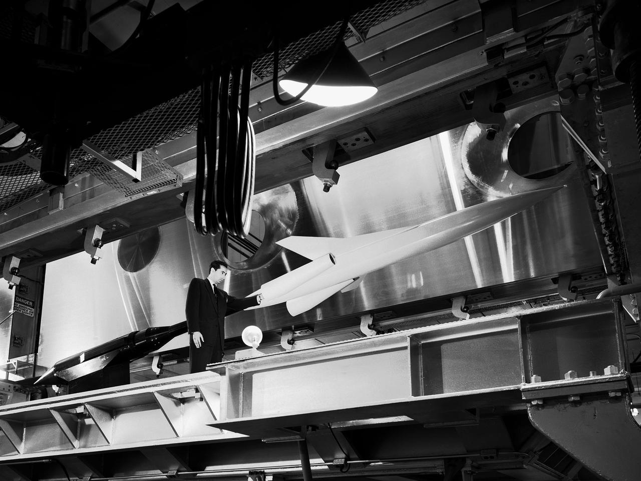
This aerial photograph shows the entire original wind tunnel complex at the National Advisory Committee for Aeronautics (NACA) Aircraft Engine Research Laboratory. The large Altitude Wind Tunnel (AWT) at the center of the photograph dominates the area. The Icing Research Tunnel to the right was incorporated into the lab’s design to take advantage of the AWT’s powerful infrastructure. The laboratory’s first supersonic wind tunnel was added to this complex just prior to this September 1945 photograph. The AWT was the nation’s only wind tunnel capable of studying full-scale engines in simulated flight conditions. The AWT’s test section and control room were within the two-story building near the top of the photograph. The exhauster equipment used to thin the airflow and the drive motor for the fan were in the building to the right of the tunnel. The unique refrigeration equipment was housed in the structure to the left of the tunnel. The Icing Research Tunnel was an atmospheric tunnel that used the AWT’s refrigeration equipment to simulate freezing rain inside its test section. A spray bar system inside the tunnel was originally used to create the droplets. The 18- by 18-inch supersonic wind tunnel was built in the summer of 1945 to take advantage of the AWT’s powerful exhaust system. It was the lab’s first supersonic tunnel and could reach Mach 1.91. Eventually the building would house three small supersonic tunnels, referred to as the “stack tunnels” because of the vertical alignment. The two other tunnels were added to this structure in 1949 and 1951.
The National Advisory Committee for Aeronautics (NACA) Aircraft Engine Research Laboratory acquired two Lockheed P–38J Lightning in October 1944 to augment their burgeoning icing research program. The P–38 was a high-altitude interceptor with a unique twin fuselage configuration. Lockheed designed the aircraft in 1938 and 1939. Its two Allison V–1710 engines carried the aircraft to altitudes up to 40,000 feet. The P–38 was used extensively during World War II in a variety of roles. In August 1943, Lockheed began producing an improved version, the P–38J that included better cockpit heating, engine cooling, and dive flaps. The military loaned the NACA two P–38Js to determine the amount of ice formation on the induction system of the turbosupercharger-equipped engines. In 1944 and 1945 one of the aircraft was subjected to ground tests using an engine blower on the hangar apron. The V–1710 was run over a full range of speeds as different levels of water were injected into the blower and sprayed onto the engine. The other P–38J was flown at 10,000 feet altitude with water sprayed into the engine to simulate rain. The tests confirmed that closing the intercooler flap added protection against the ice by blocking water ingestion and increasing engine heat. NACA pilot Joseph Walker joined the Cleveland laboratory in early 1945 as a physicist. Walker had flown P–38s during World, and later claimed that seeing the NACA’s two P–38Js inspired him to return to his earlier calling as a pilot, this time with the NACA. Walker was particularly active in the icing flight program during his five years of flying in Cleveland.
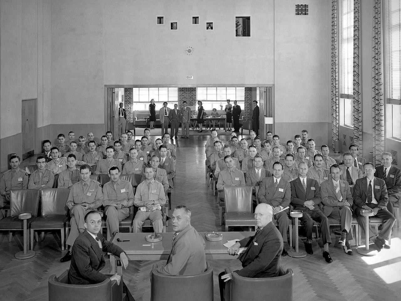
A group of 60 Army Air Forces officers visited the National Advisory Committee for Aeronautics (NACA) Aircraft Engine Research Laboratory on August 27, 1945. The laboratory enacted strict security regulations throughout World War II. During the final months of the war, however, the NACA began opening its doors to groups of writers, servicemen, and aviation industry leaders. These events were the first exposure of the new engine laboratory to the outside world. Grandstands were built alongside the Altitude Wind Tunnel specifically for group photographs. George Lewis, Raymond Sharp, and Addison Rothrock (right to left) addressed this group of officers in the Administration Building auditorium. Lewis was the NACA’s Director of Aeronautical Research, Sharp was the lab’s manager, and Rothrock was the lab’s chief of research. Abe Silverstein, Jesse Hall and others watch from the rear of the room. The group toured several facilities after the talks, including the Altitude Wind Tunnel and a new small supersonic wind tunnel. The visit concluded with a NACA versus Army baseball game and cookout.
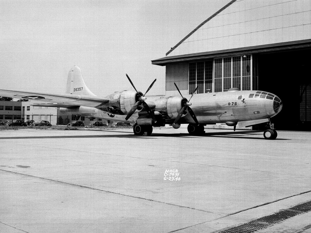
A Boeing B–29 Superfortress at the National Advisory Committee for Aeronautics (NACA) Aircraft Engine Research Laboratory in Cleveland, Ohio. The B–29 was the Army Air Forces’ deadliest weapon during the latter portion of World War II. The aircraft was significantly larger than previous bombers but could fly faster and higher. The B–29 was intended to soar above anti-aircraft fire and make pinpoint drops onto strategic targets. The bomber was forced to carry 20,000 pounds more armament than it was designed for. The extra weight pushed the B–29’s four powerful Wright R–3350 engines to their operating limits. The over-heating of the engines proved to be a dangerous problem. The military asked the NACA to tackle the issue. Full-scale engine tests on a R–3350 engine in the Prop House demonstrated that a NACA-designed impeller increased the flow rate of the fuel injection system. Altitude Wind Tunnel studies of the engine led to the reshaping of cowling inlet and outlet to improve airflow and reduce drag. Single-cylinder studies on valve failures were resolved by a slight extension of the cylinder head, and the Engine Research Building researchers combated uneven heating with a new fuel injection system. The modifications were then tried out on an actual B–29. The bomber arrived in Cleveland on June 22, 1944. The new injection impeller, ducted head baffles and instrumentation were installed on the bomber’s two left wing engines. Eleven test flights were flown over the next month with military pilots at the helm. Overall the flight tests corroborated the wind tunnel and test stand studies.
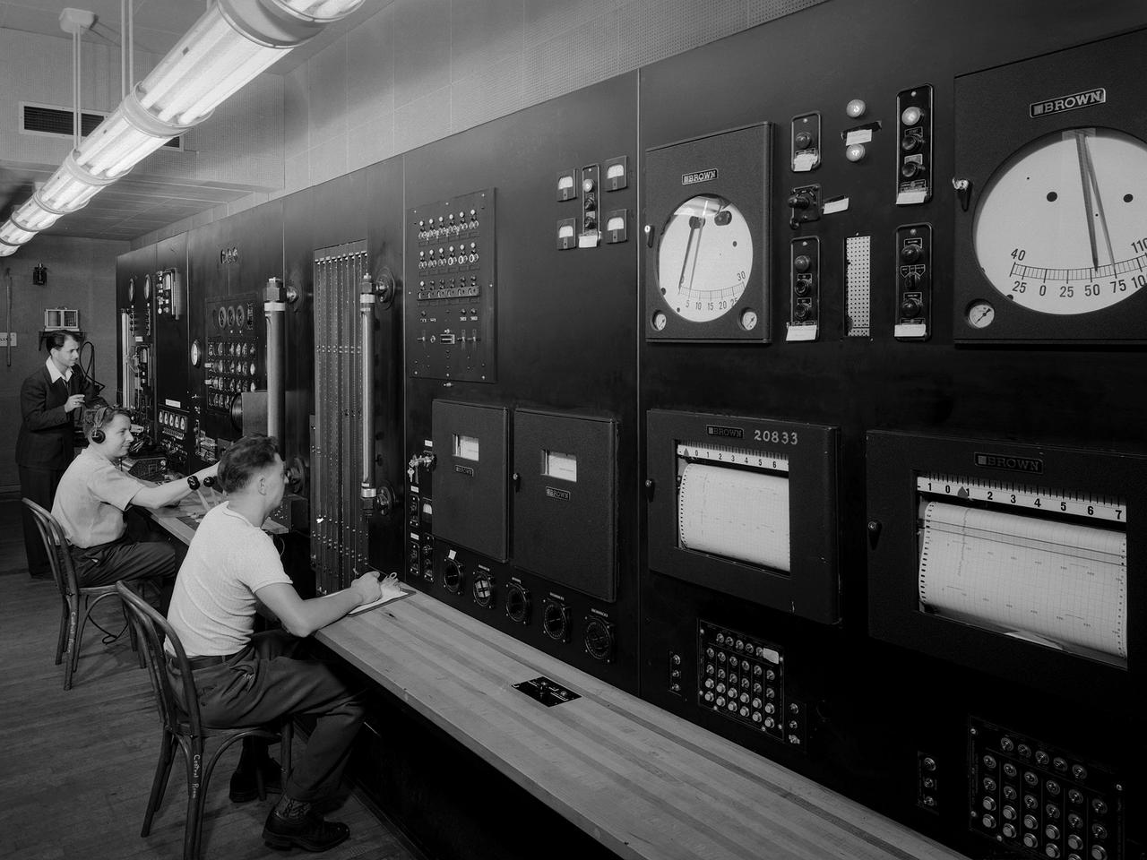
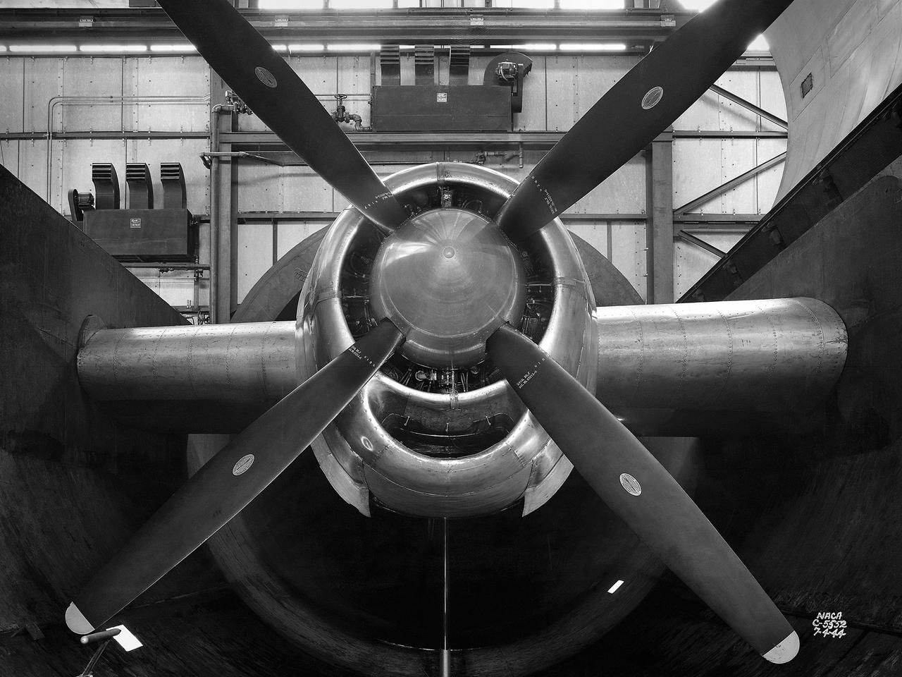
Operators in the control room for the Altitude Wind Tunnel at the National Advisory Committee for Aeronautics (NACA) Aircraft Engine Research Laboratory remotely operate a Wright R–3350 engine in the tunnel’s test section. Four of the engines were used to power the B–29 Superfortress, a critical weapon in the Pacific theater during World War II. The wind tunnel, which had been in operation for approximately six months, was the nation’s only wind tunnel capable of testing full-scale engines in simulated altitude conditions. The soundproof control room was used to operate the wind tunnel and control the engine being run in the test section. The operators worked with assistants in the adjacent Exhauster Building and Refrigeration Building to manage the large altitude simulation systems. The operator at the center console controlled the tunnel’s drive fan and operated the engine in the test section. Two sets of pneumatic levers near his right forearm controlled engine fuel flow, speed, and cooling. Panels on the opposite wall, out of view to the left, were used to manage the combustion air, refrigeration, and exhauster systems. The control panel also displayed the master air speed, altitude, and temperature gauges, as well as a plethora of pressure, temperature, and airflow readings from different locations on the engine. The operator to the right monitored the manometer tubes to determine the pressure levels. Despite just being a few feet away from the roaring engine, the control room remained quiet during the tests.
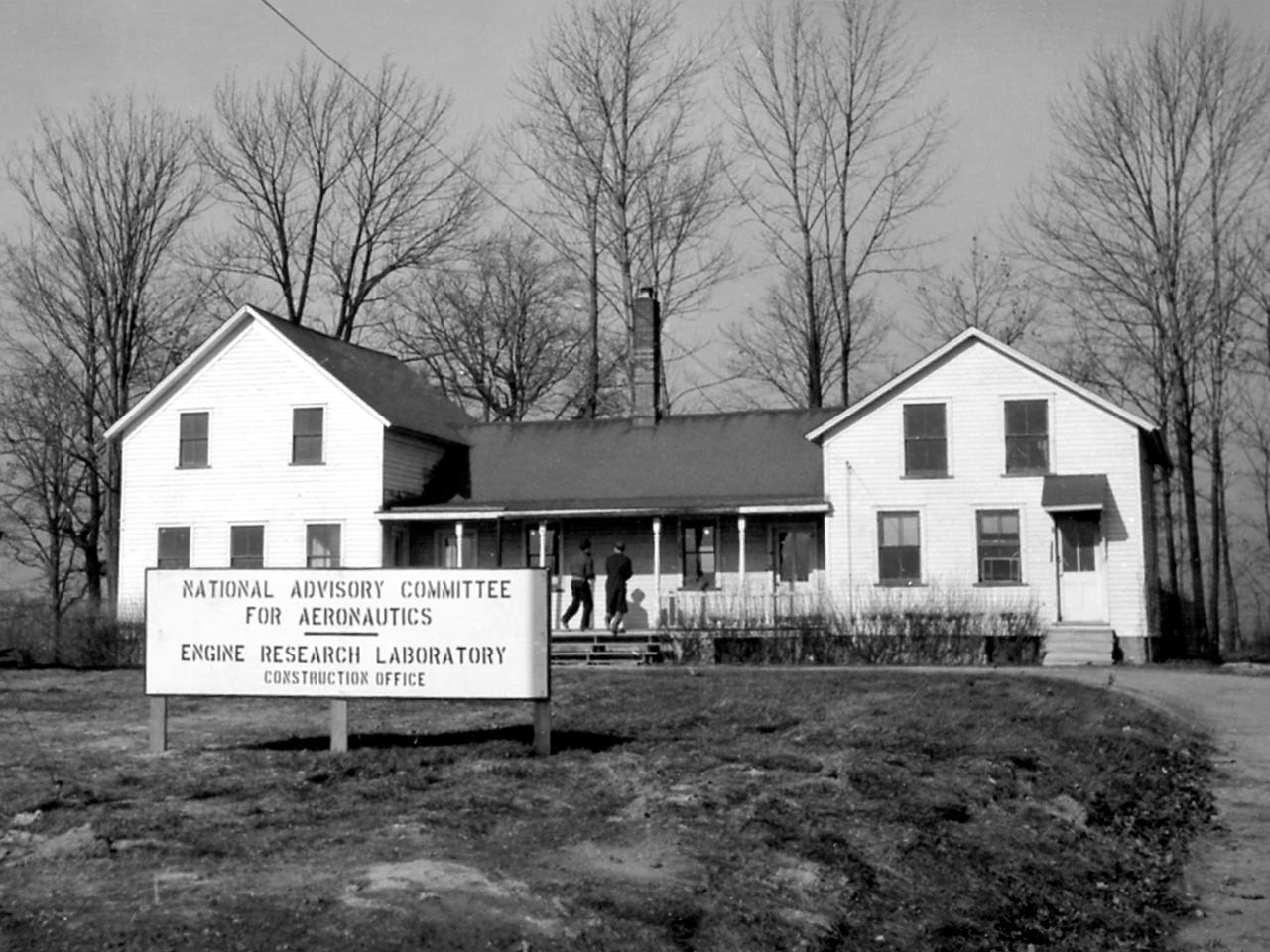
The construction offices for the National Advisory Committee for Aeronautics’ (NACA) new Aircraft Engine Research Laboratory were originally opened in a small Radio House on the adjacent airport property. By July 1941, the staff had expanded to the point that a new shelter was needed. The NACA took possession of what was thereafter referred to as the “Farm House.” It was the only residential structure at the site. The Farm House served as the NACA’s main office until the Administration Building was opened in December 1942. The Farm House was built in 1827 and purchased by J.B. Perkins in 1849. Perkins did not reside in the house but hired caretakers to maintain the house and property and raise horses. The disposition of the land in the years leading up to the NACA’s takeover is not clear. After World War II, NACA management did not want visitors’ first impression to be an old farm house. The building was significantly modified to improve its size, appearance, shape, and added many modern conveniences. In the early 1950s the entire structure was relocated to the lot directly behind the Administration Building. It contained personnel and administrative offices for the lab. The Farm House was eventually demolished in 1973 due to deterioration of the wooden structure.
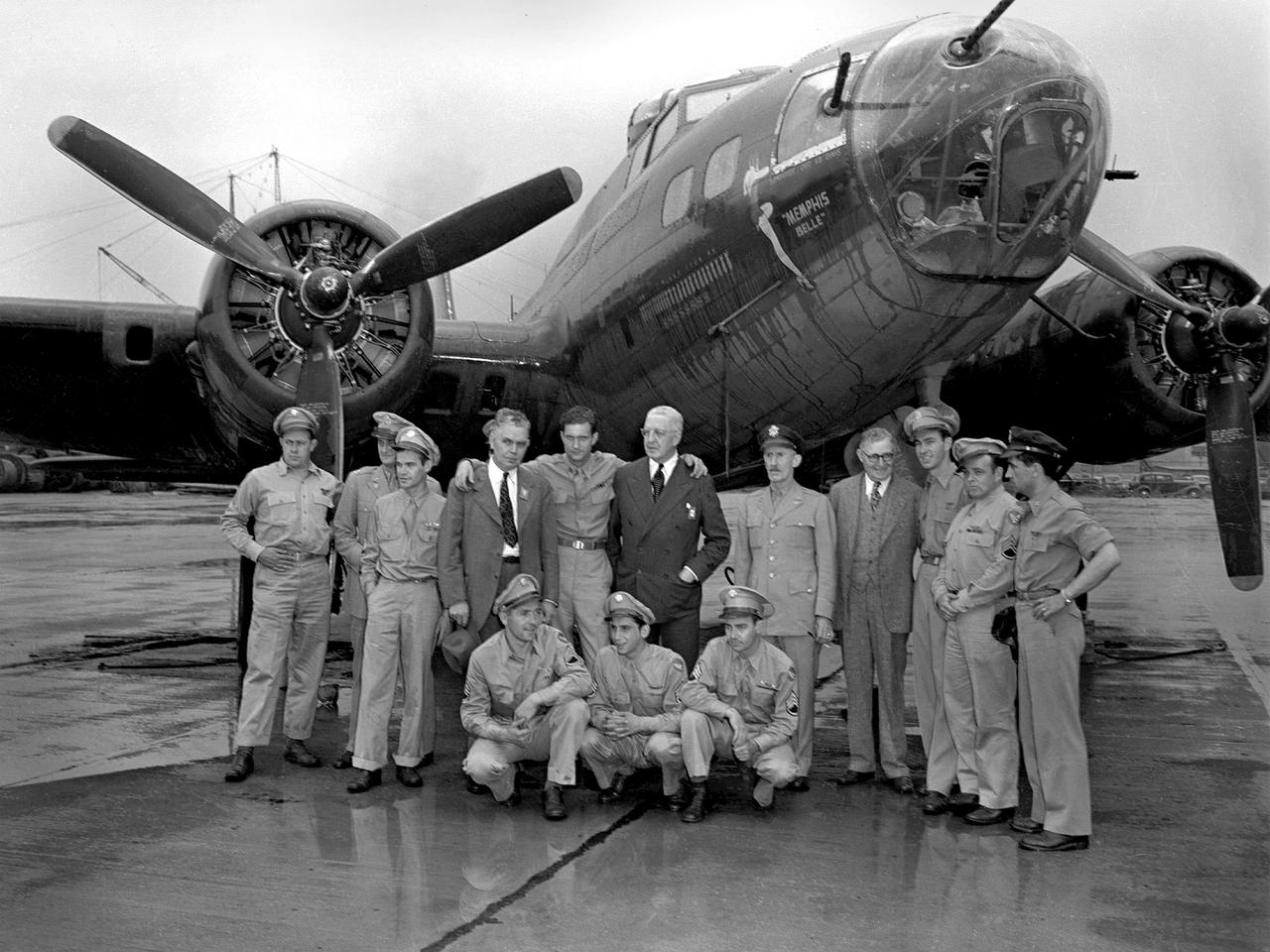
Captain Robert Morgan and the rest of the Memphis Belle crew arrive in Cleveland on a rainy July 7, 1943, for three-day publicity visit. This B–17 Flying Fortress had recently become the first U.S. bomber to complete 25 missions over Germany and France. The lack of long distance escort fighters made the feat even more remarkable. The Memphis Belle and its crew returned to the United States in June and were immediately thrown into a three-month-long war bond tour. While in Cleveland the crew toured the National Advisory Committee for Aeronautics (NACA) Aircraft Engine Research Laboratory, the Cleveland Bomber Plant, and Thompson Products. In the evenings they were feted downtown by the Chamber of Commerce at the Hotel Cleveland. A local company brought Morgan’s family and his fiancé—the Memphis Belle’s inspiration—to Cleveland to participate in the activities. The bomber was on display to the public near the airport’s fenceline and stored in the NACA’s hangar overnight. Pictured in this photograph from left to right: Robert Hanson, Vincent Evans, Charles Leighton, NACA Manager Raymond Sharp, Robert Morgan, William Holliday of the Chamber of Commerce, Army Liaison Officer Colonel Edwin Page, Airport Commissioner Jack Berry, Cecil Scott, John Quinlan and James Verinis. Kneeling are Harold Loch, Casimer Nastal and Charles Wichell.
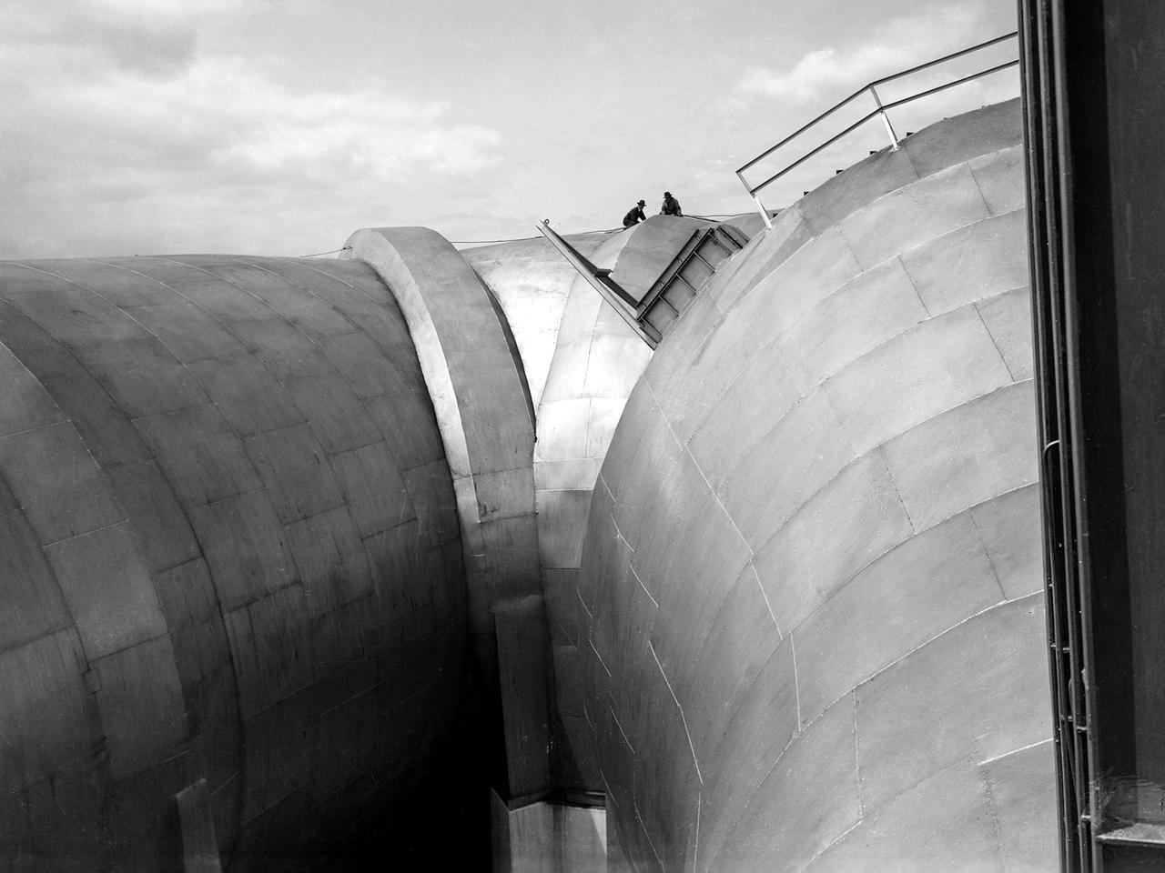
Two men on top of the Altitude Wind Tunnel (AWT) at the National Advisory Committee for Aeronautics (NACA) Aircraft Engine Research Laboratory. The tunnel was a massive rectangular structure, which for years provided one of the highest vantage points on the laboratory. The tunnel was 263 feet long on the north and south legs and 121 feet long on the east and west sides. The larger west end of the tunnel, seen here, was 51 feet in diameter. The east side of the tunnel was 31 feet in diameter at the southeast corner and 27 feet in diameter at the northeast. The throat section, which connected the northwest corner to the test section, narrowed sharply from 51 to 20 feet in diameter. The AWT’s altitude simulation required temperature and pressure fluctuations that made the design of the shell more difficult than other tunnels. The simultaneous decrease in both pressure and temperature inside the facility produced uneven stress loads, particularly on the support rings. The steel used in the primary tunnel structure was one inch thick to ensure that the shell did not collapse as the internal air pressure was dropped to simulate high altitudes. It was a massive amount of steel considering the World War II shortages. The shell was covered with several inches of fiberglass insulation to retain the refrigerated air and a thinner outer steel layer to protect the insulation against the weather. A unique system of rollers was used between the shell and its support piers. These rollers allowed for movement as the shell expanded or contracted during the altitude simulations. Certain sections would move as much as five inches during operation.

Commemorating the NACA Aircraft Engine Research Laboratory Ground Breaking Ceremony

The Flight Operations crew stands before a Republic P-47G Thunderbolt at the National Advisory Committee for Aeronautics (NACA) Aircraft Engine Research Laboratory in Cleveland, Ohio. The laboratory’s Flight Research Section was responsible for conducting a variety of research flights. During World War II most of the test flights complemented the efforts in ground-based facilities to improve engine cooling systems or study advanced fuel mixtures. The Republic P–47G was loaned to the laboratory to test NACA modifications to the Wright R–2800 engine’s cooling system at higher altitudes. The laboratory has always maintained a fleet of aircraft so different research projects were often conducted concurrently. The flight research program requires an entire section of personnel to accomplish its work. This staff generally consists of a flight operations group, which includes the section chief, pilots and administrative staff; a flight maintenance group with technicians and mechanics responsible for inspecting aircraft, performing checkouts and installing and removing flight instruments; and a flight research group that integrates the researchers’ experiments into the aircraft. The staff at the time of this March 1944 photograph included 3 pilots, 16 planning and analysis engineers, 36 mechanics and technicians, 10 instrumentation specialists, 6 secretaries and 5 computers.
The first research assignment specifically created for the National Advisory Committee for Aeronautics’ (NACA) new Aircraft Engine Research Laboratory was the integration of a supercharger into the Allison V–1710 engine. The military was relying on the liquid-cooled V–1710 to power several types of World War II fighter aircraft and wanted to improve the engine's speed and altitude performance. Superchargers forced additional airflow into the combustion chamber, which increased the engine’s performance resulting in greater altitudes and speeds. They also generated excess heat that affected the engine cylinders, oil, and fuel. In 1943 the military tasked the new Aircraft Engine Research Laboratory to integrate the supercharger, improve the cooling system, and remedy associated engine knock. Three Allison engines were provided to the laboratory’s research divisions. One group was tasked with improving the supercharger performance, another analyzed the effect of the increased heat on knock in the fuel, one was responsible for improving the cooling system, and another would install the new components on the engine with minimal drag penalties. The modified engines were installed on this 2000-horsepower dynamotor stand in a test cell within the Engine Research Building. The researchers could run the engine at different temperatures, fuel-air ratios, and speeds. When the modifications were complete, the improved V–1710 was flight tested on a P–63A Kingcobra loaned to the NACA for this project.
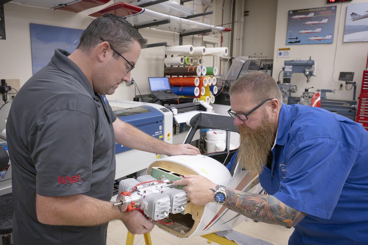
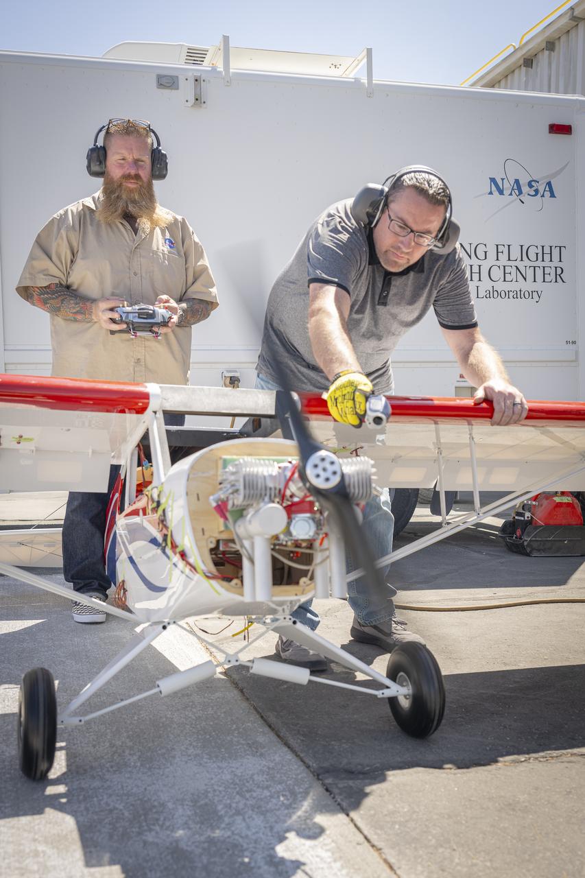
Justin Link, left, and Justin Hall attach an engine onto a subscale aircraft on Wednesday, Sept. 3, 2025, at NASA’s Armstong Flight Research Center in Edwards, California. Link is a pilot for small uncrewed aircraft systems at the center’s Dale Reed Subscale Flight Research Laboratory and Hall is the lab’s chief pilot.
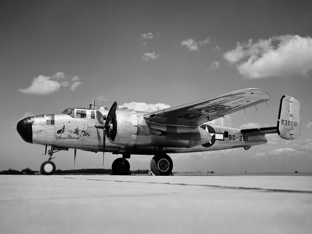
A Wright Aeronautical R–2600 Cyclone piston engine installed in the Engine Propeller Research Building, or Prop House, at the National Advisory Committee for Aeronautics (NACA) Aircraft Engine Research Laboratory. The R–2600 was among the most powerful engines that emerged during World War II. The engine, which was developed for commercial applications in 1939, was used to power the North American B–25 bomber and several other midsize military aircraft. The higher altitudes required by the military caused problems with the engine's cooling and fuel systems. The military requested that the Aircraft Engine Research Laboratory analyze the performance of the R–2600, improve its cooling system, and reduce engine knock. The NACA researchers subjected the engine to numerous tests in its Prop House. The R–2600 was the subject of the laboratory's first technical report, which was written by members of the Fuels and Lubricants Division. The Prop House contained soundproof test cells in which piston engines and propellers were mounted and operated at high powers. Electrically driven fans drew air through ducts to create a stream of cooling air over the engines. Researchers tested the performance of fuels, turbochargers, water-injection and cooling systems here during World War II. The facility was also investigated a captured German V–I buzz bomb during the war.
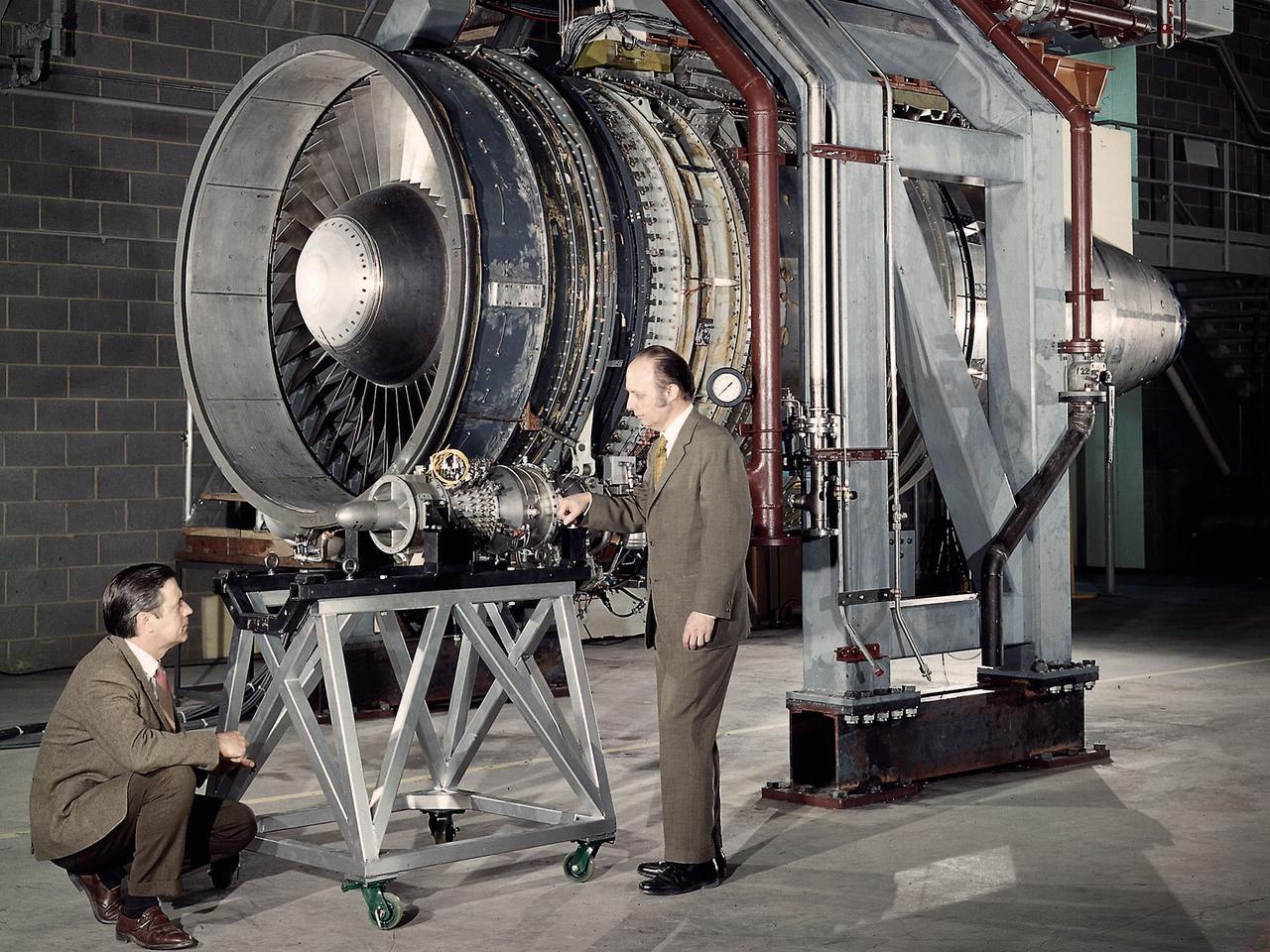
Researchers Robert Cummings, left, and Harold Gold with the small Low Cost Engine in the shadow of the much larger Quiet Engine at the National Aeronautics and Space Administration (NASA) Lewis Research Center. The two engines were being studied in different test cells at the Propulsion Systems Laboratory. Jet engines had proven themselves on military and large transport aircraft, but their use on small general aviation aircraft was precluded by cost. Lewis undertook a multiyear effort to develop a less expensive engine to fill this niche using existing technologies. Lewis researchers designed a four-stage, axial-flow engine constructed from sheet metal. It was only 11.5 inches in diameter and weighed 100 pounds. The final design specifications were turned over to a manufacturer in 1972. Four engines were created, and, as expected, the fabrication and assembly of the engine were comparatively inexpensive. In 1973 the Low Cost Engine had its first realistic analysis in the Propulsion Systems Laboratory altitude tank. The engine successfully operated at speeds up to Mach 1.24 and simulated altitudes of 30,000 feet. NASA released the engine to private industry in the hope that design elements would be incorporated into future projects and reduce the overall cost of small jet aircraft. Small jet and turboprop engines became relatively common in general aviation aircraft by the late 1970s.
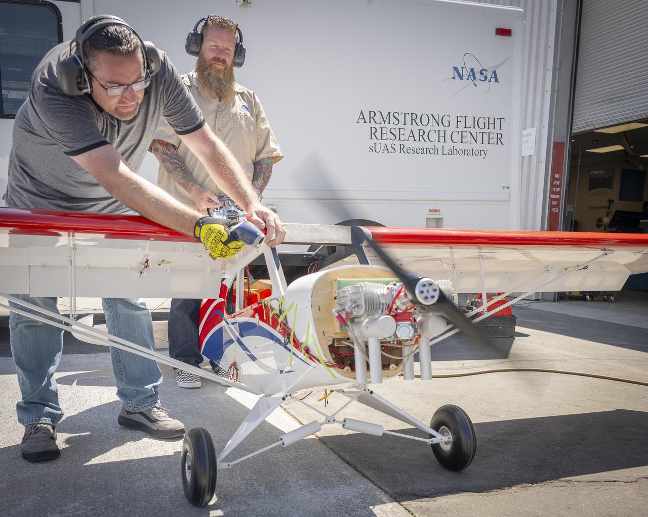
Justin Link, left, holds the subscale aircraft in place, while Justin Hall manages engine speed during preliminary engine tests on Friday, Sept. 12, 2025, at NASA’s Armstong Flight Research Center in Edwards, California. Link is a pilot for small uncrewed aircraft systems at the center’s Dale Reed Subscale Flight Research Laboratory and Hall is the chief pilot.
Justin Hall, left, controls a subscale aircraft as Justin Link holds the aircraft in place during preliminary engine tests on Friday, Sept. 12, 2025, at NASA’s Armstong Flight Research Center in Edwards, California. Hall is chief pilot at the center’s Dale Reed Subscale Flight Research Laboratory and Link is a pilot for small uncrewed aircraft systems.

The sign near the entrance of the National Advisory Committee for Aeronautics (NACA) Flight Propulsion Research Laboratory. The name was changed several weeks later to the Lewis Flight Propulsion Laboratory in honor of the NACA’s former Director of Aeronautical Research, George W. Lewis. The research laboratory has had five different names since its inception in 1941. The Cleveland laboratory was originally known as the NACA Aircraft Engine Research Laboratory. In 1947 it was renamed the NACA Flight Propulsion Research Laboratory to reflect the expansion of the research activities beyond just engines. Following the death of George Lewis, the name was changed to the NACA Lewis Flight Propulsion Laboratory in September 1948. On October 1, 1958, the lab was incorporated into the new NASA space agency, and it was renamed the NASA Lewis Research Center. Following John Glenn’s flight on the space shuttle, the name was changed again to the NASA Glenn Research Center on March 1, 1999. From his office in Washington DC, George Lewis managed the aeronautical research conducted at the NACA for over 20 years. His most important accomplishment, however, may have been an investigative tour of German research facilities in the fall of 1936. The visit resulted in the broadening of the scope of the NACA’s research and the physical expansion that included the new engine laboratory in Cleveland.
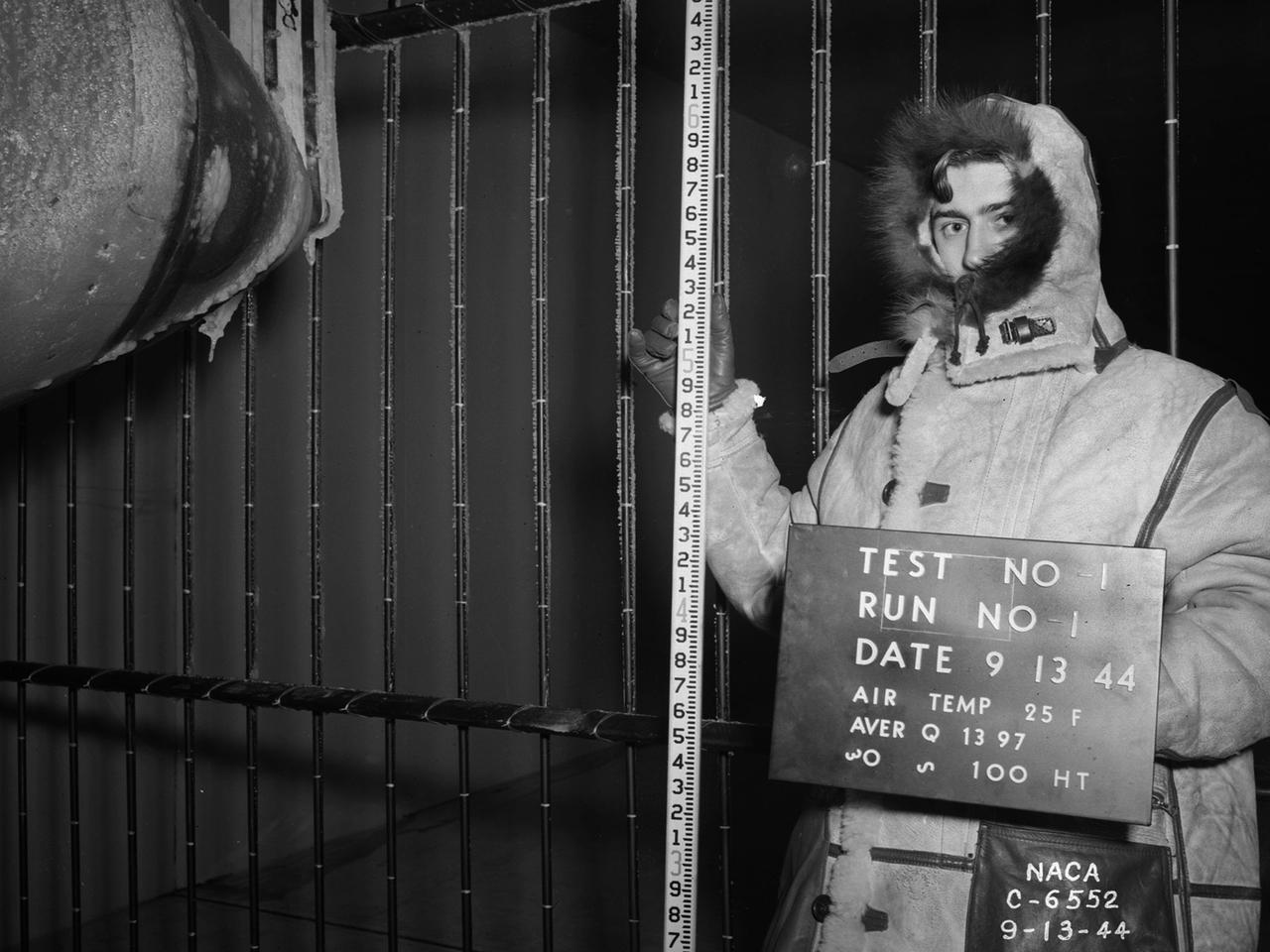
National Advisory Committee for Aeronautics (NACA) design engineers added the Icing Research Tunnel to the new Aircraft Engine Research Laboratory’s original layout to take advantage of the massive refrigeration system being constructed for the Altitude Wind Tunnel. The Icing Research Tunnel was built to study the formation of ice on aircraft surfaces and methods of preventing or eradicating that ice. Ice buildup adds extra weight, effects aerodynamics, and sometimes blocks airflow through engines. The Icing Research Tunnel is a closed-loop atmospheric wind tunnel with a 6- by 9-foot test section. The tunnel can produce speeds up to 300 miles per hour and temperatures from about 30 to –45⁰ F. Initially the tunnel used a spray bar system to introduce moisture into the airstream. NACA engineers struggled for nearly 10 years to perfect the spray system. The Icing Research Tunnel began testing in June of 1944. Initial testing, seen in this photograph, studied ice accumulation on propellers of a military aircraft. NACA reserach also produced a protected air scoop for the C–46 transport aircraft. A large number of C–46 aircraft were lost due to icing while flying supply runs over the Himalayas during World War II.
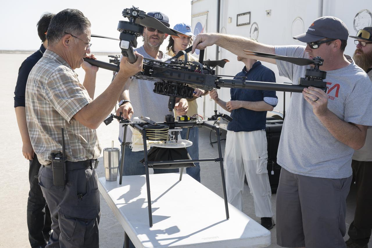
Derek Abramson, left, chief engineer for the Dale Reed Subscale Flight Research Laboratory, and Justin Link, small unmanned aircraft systems pilot, prepare an atmospheric probe model for flight on Oct. 22, 2024. A quad rotor remotely piloted aircraft released the probe above Rogers Dry Lake, a flight area adjacent to NASA’s Armstrong Flight Research Center in Edwards, California. The probe was designed and built at the center.
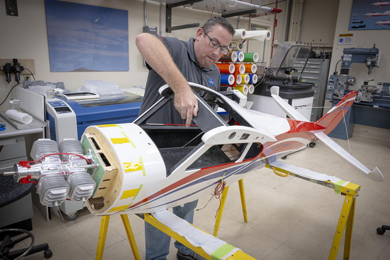
Justin Link turns a subscale aircraft on its side to continue work to mark where the engine cowl will go and where to line it up for attachment on Wednesday, Sept. 3, 2025, at NASA’s Armstong Flight Research Center in Edwards, California. Link is a pilot for small uncrewed aircraft systems at the center’s Dale Reed Subscale Flight Research Laboratory.
A flight engineer at the National Advisory Committee for Aeronautics (NACA) Aircraft Engine Research Laboratory monitors test equipment in the rear of the Lockheed RA–29 Hudson. Lockheed manufactured several variations of the light bomber in the late 1930s. The Hudson was one of the few military aircraft models available in large quantities during the early years of World War II, and both the US and British air forces utilized it as a patrol aircraft. The RA–29s were soon superseded by newer aircraft, but continued to serve as crew trainers, light cargo carriers and staff transports. The NACA flight engineers in the Planning and Analysis Section were responsible for working with researchers to install and monitor the experimental equipment on the NACA’s research aircraft. This process could require weeks or months. When larger aircraft, like the RA–29 Hudson, were utilized the flight engineers often participated in the flights. The NACA acquired their RA–29 in November 1943, and used the aircraft for fuel blend studies and instrumentation development. The Hudson also frequently served as a transportation vehicle for the staff and visitors. The RA–29 was transferred from the NACA in July 1945.
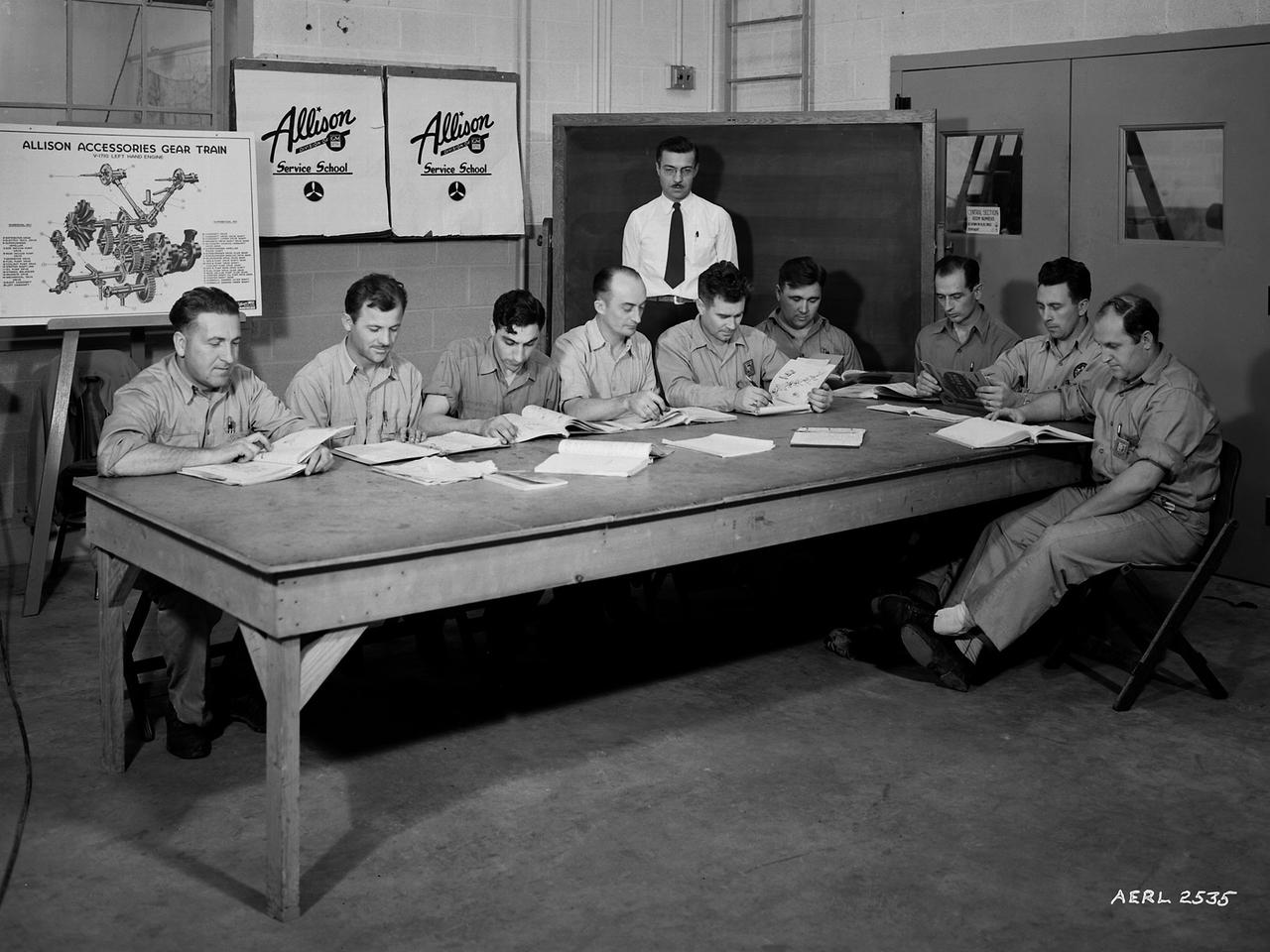
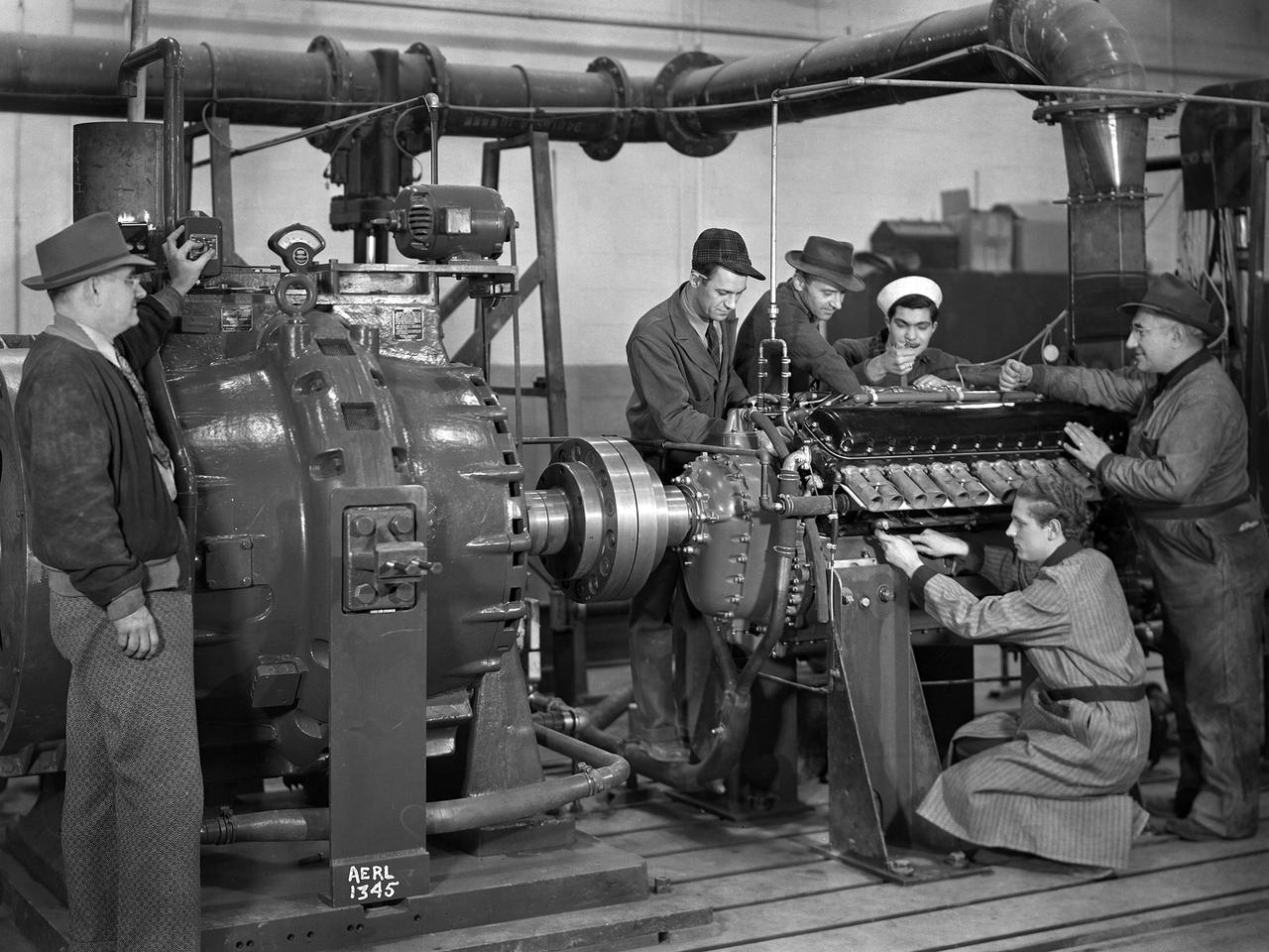
The Allison Engine Company's A.G. Covell instructs mechanics from various divisions at the National Advisory Committee for Aeronautics (NACA) Aircraft Engine Research Laboratory on the operation of the Allison Basic Engine. The military had asked that the laboratory undertake an extensive program to improve the performance of the Allison V–1710 engine. The V–1710 was the only liquid-cooled engine used during World War II, and the military counted on it to power several types of fighter aircraft. The NACA instituted an Apprentice Program during the war to educate future mechanics, technicians, and electricians. The program was suspended for a number of years due to the increasing rates of military service by its participants. The laboratory continued its in-house education during the war, however, by offering a number of classes to its employees and lectures for the research staff. The classes and lectures were usually taught by fellow members of the staff, but occasionally external experts were brought in. The students in the Allison class in the Engine Research Building were taught how to completely disassemble and reassemble the engine components and systems. From left to right are Don Vining, Ed Cudlin, Gus DiNovo, George Larsen, Charles Diggs, Martin Lipes, Harley Roberts, Martin Berwaldt and John Dempsey. A.G. Covell is standing.
Derek Abramson, left, chief engineer for the Dale Reed Subscale Flight Research Laboratory, and Justin Link, small unmanned aircraft system pilot, carry the atmospheric probe model and a quad rotor remotely piloted aircraft to position it for flight on Oct. 24, 2024. John Bodylski, probe principal investigator, right, and videographer Jacob Shaw watch the preparations. Once at altitude, the quad rotor aircraft released the probe above Rogers Dry Lake, a flight area adjacent to NASA’s Armstrong Flight Research Center in Edwards, California. The probe was designed and built at the center.
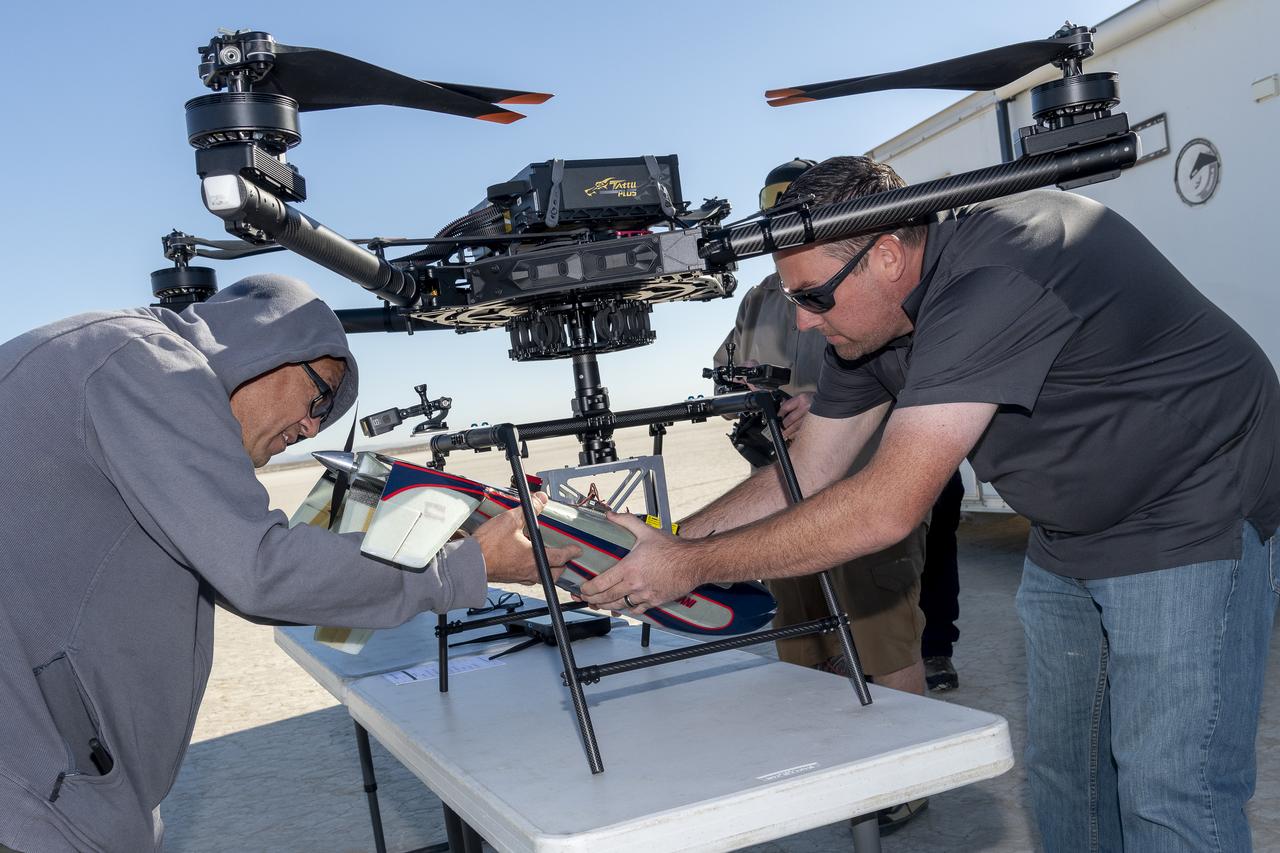
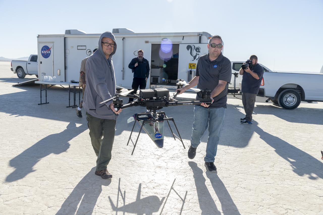
Derek Abramson, left, and Justin Link, right, attach an Alta X drone to the Enhancing Parachutes by Instrumenting the Canopy test experiment on June 4, 2025, at NASA’s Armstong Flight Research Center in Edwards, California. Abramson is NASA chief engineer at the center’s Dale Reed Subscale Flight Research Laboratory, where Link also works as a pilot for small uncrewed aircraft systems. NASA researchers are developing technology to make supersonic parachutes safer and more reliable for delivering science instruments and payloads to Mars.
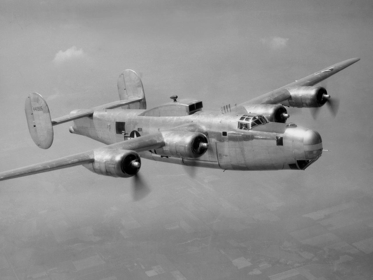
A Consolidated B-25M Liberator modified for icing research by the National Advisory Committee for Aeronautics (NACA) Lewis Flight Propulsion Laboratory. NACA Lewis performed a limited amount of icing research during World War II, but the program expanded significantly in 1946. The accumulation of ice on aircraft was a continual problem. The ice formations could result in extra weight, aerodynamic penalties, and blockage engine inlets. Although the Lewis icing researchers utilized numerous aircraft, the program’s two workhorses were the B-24M Liberator, seen here, and a North American XB-25E Mitchell. The Consolidated Aircraft Company created the four-engine bomber in the early 1940s. During World War II the bomber was employed on long-duration bombing missions in both Europe and the Pacific. Production of the B-24M version did not begin until October 1944 with the end of the war in Europe approaching. This resulted in scores of unneeded bombers when hostilities ended. This B-24M arrived at the NACA Lewis laboratory in November 1945. At Lewis the B-24M was repeatedly modified to study ice accretion on aircraft components. Researchers analyzed different anti-icing and deicing strategies and gathered statistical ice measurement data. The B-24M was also used to study ice buildup on jet engines. A General Electric I-16 engine was installed in the aircraft’s waist compartment with an air scoop on the top of the aircraft to duct air to the engine. Water spray nozzles inside the aircraft were employed to simulate icing conditions at the turbojet’s inlet.
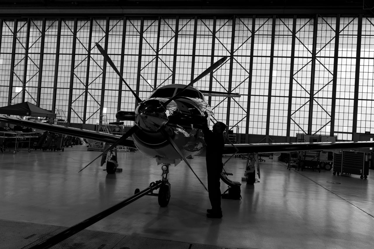
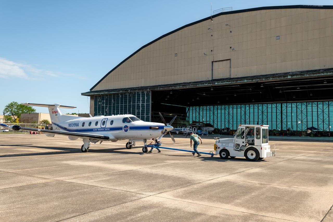
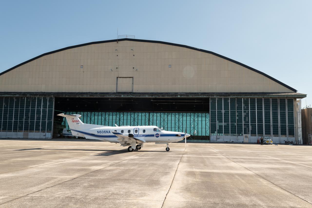
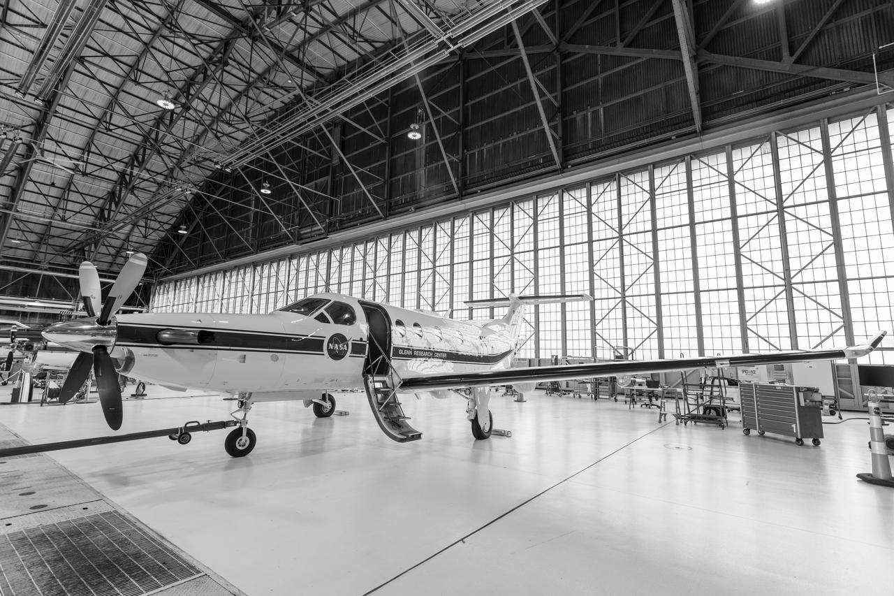
Pilatus PC-12 Aircraft Being Prepped for Takeoff on June 12, 2024. A team at NASA’s Glenn Research Center in Cleveland streamed 4K video footage from an aircraft to the International Space Station and back for the first time using optical, or laser, communications. The feat was part of a series of tests on new technology that could provide live video coverage of astronauts on the Moon during the Artemis missions. Working with the Air Force Research Laboratory and NASA’s Small Business Innovation Research program, Glenn engineers temporarily installed a portable laser terminal on the belly of a Pilatus PC-12 aircraft. They then flew over Lake Erie sending data from the aircraft to an optical ground station in Cleveland. From there, it was sent over an Earth-based network to NASA’s White Sands Test Facility in Las Cruces, New Mexico, where scientists used infrared light signals to send the data. Photo Credit: (NASA/Sara Lowthian-Hanna)
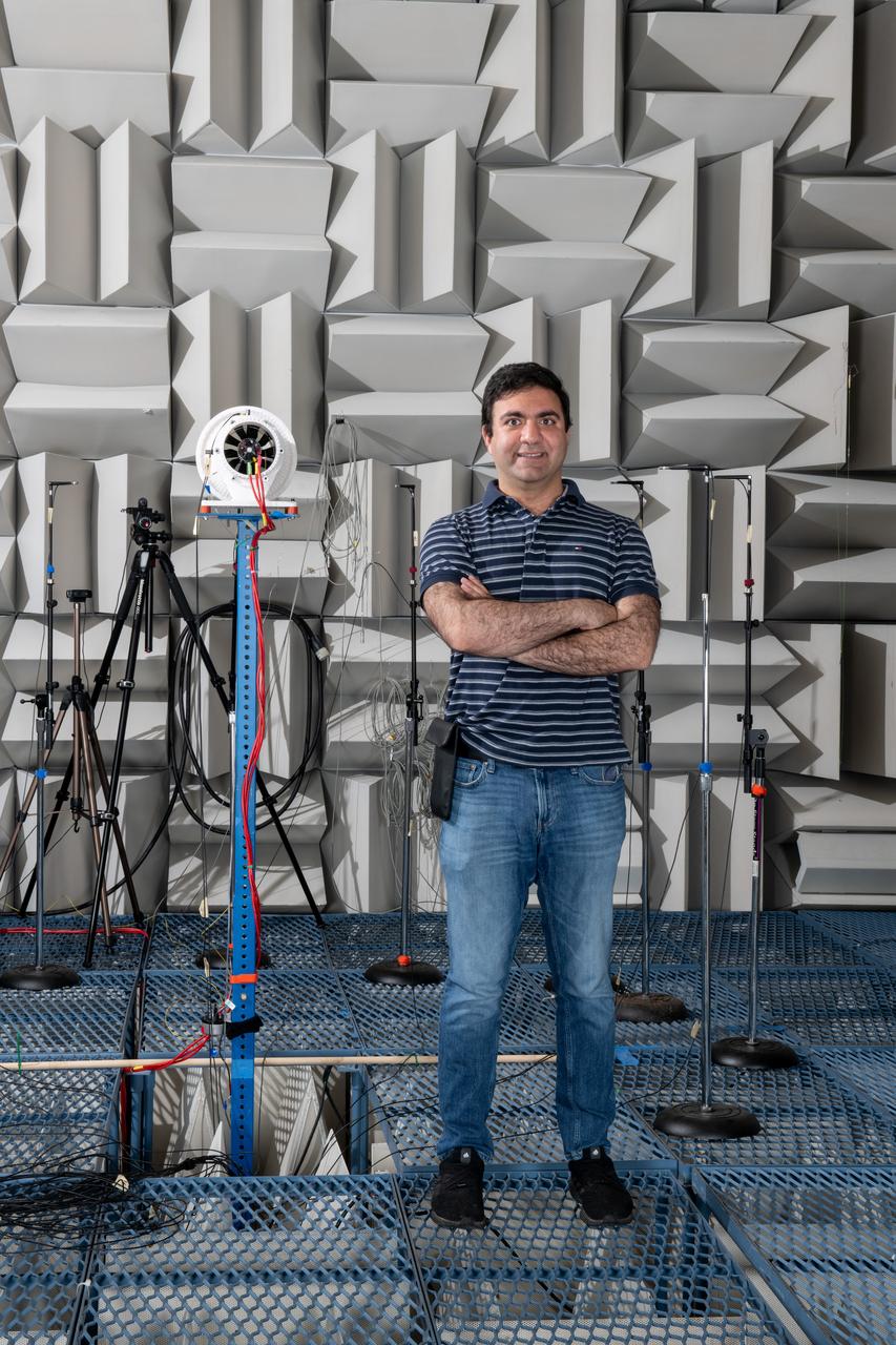
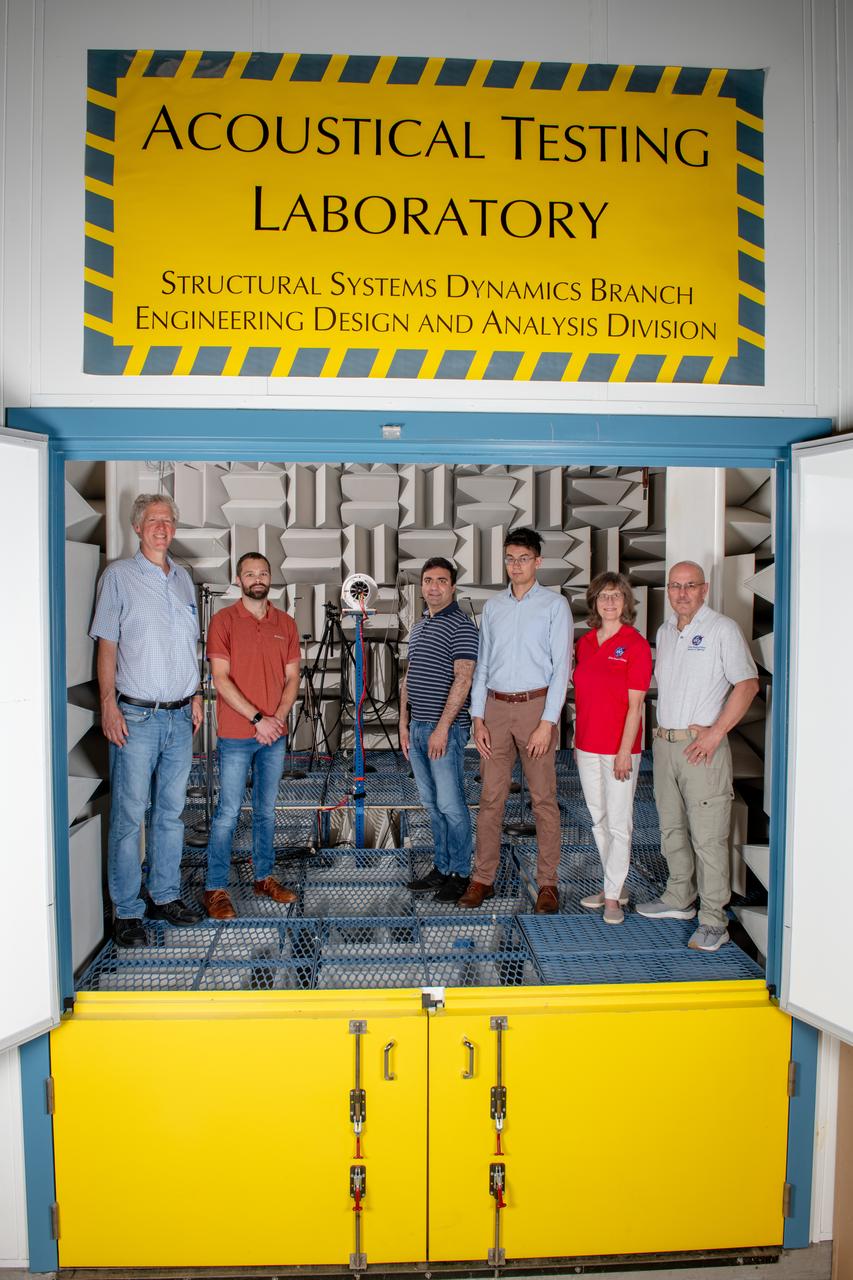
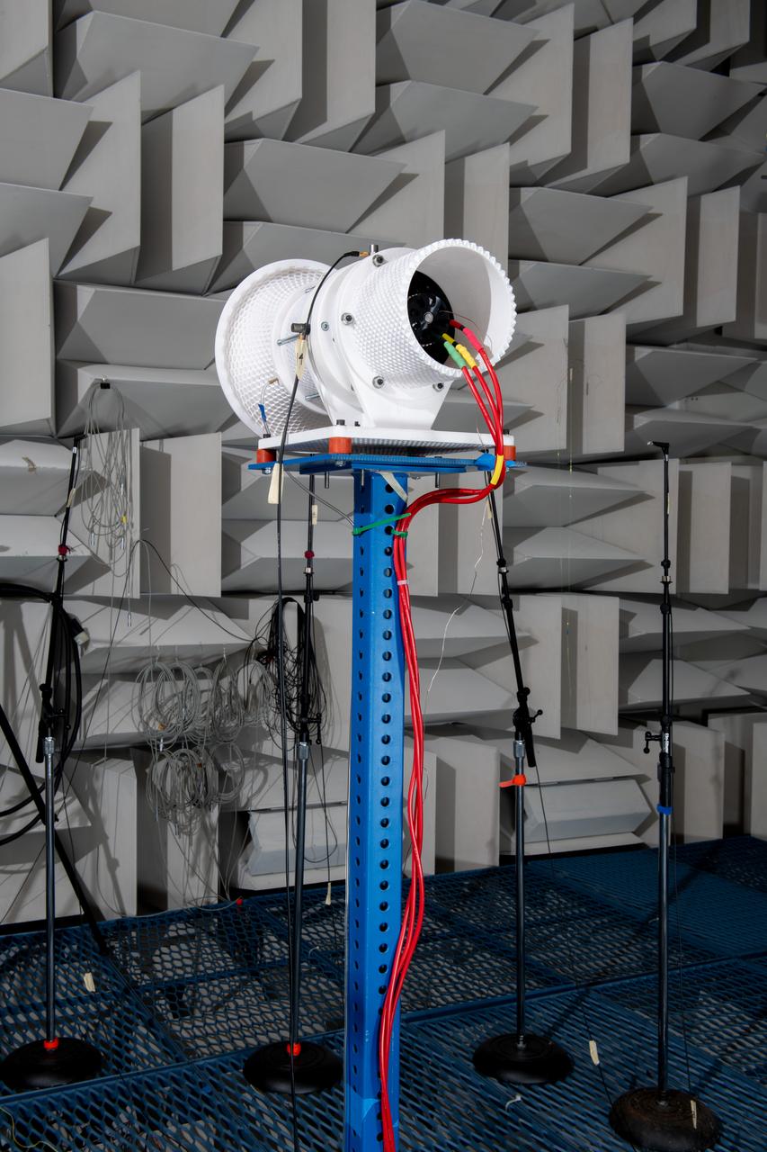
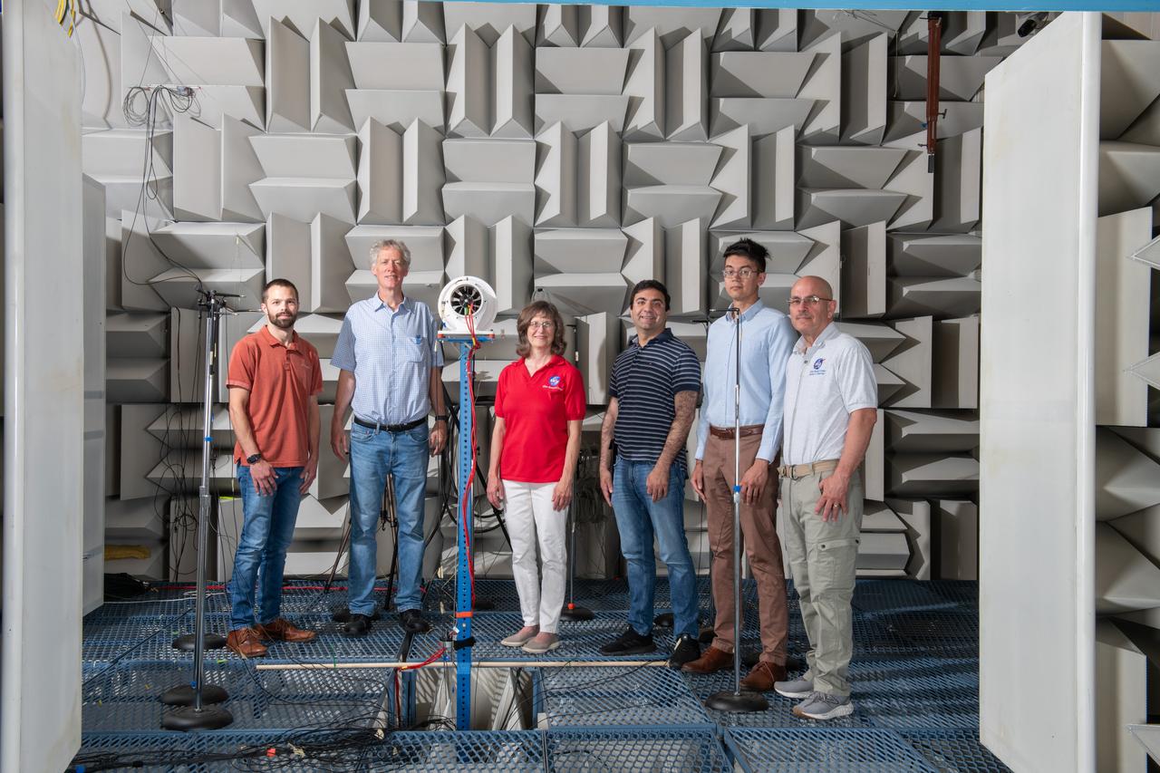
The Quiet Electric Engine V1 (QUEEN V1) experiment that was performed in the NASA GRC Acoustical Testing Laboratory (ATL). Equipment is installed in the anechoic chamber and in the adjacent control room. In response to the pervasive health and environmental problems associated with aviation noise and air pollution, NASA’s Quiet Electric Engine (QUEEN) team is working to increase the peace and quiet in the world by researching ways to make engines for large single-aisle aircraft safer, cleaner, and quieter. Posing with the experiment is aerospace engineer, Jonathan M. Goodman.
The resolution of the Boeing B-29 Superfortress’ engine cooling problems was one of the Aircraft Engine Research Laboratory’s (AERL) key contributions to the World War II effort. The B-29 leapfrogged previous bombers in size, speed, and altitude capabilities. The B–29 was intended to soar above anti-aircraft fire and make pinpoint bomb drops onto strategic targets. Four Wright Aeronautical R-3350 engines powered the massive aircraft. The engines, however, frequently strained and overheated due to payload overloading. This resulted in a growing number of engine fires that often resulted in crashes. The military asked the NACA to tackle the overheating issue. Full-scale engine tests on a R–3350 engine in the Prop House demonstrated that a NACA-designed impeller increased the fuel injection system’s flow rate. Single-cylinder studies resolved a valve failure problem by a slight extension of the cylinder head, and researchers in the Engine Research Building combated uneven heating with a new fuel injection system. Investigations during the summer of 1944 in the Altitude Wind Tunnel, which could simulate flight conditions at high altitudes, led to reduction of drag and improved air flow by reshaping the cowling inlet and outlet. The NACA modifications were then flight tested on a B-29 bomber that was brought to the AERL.
In 1946 the Lewis Flight Propulsion Laboratory became the NACA’s official icing research center. In addition to the Icing Research Tunnel, the lab possessed several aircraft modified for icing work, including a Consolidated B-24M Liberator and a North American XB-25E Mitchell, seen here. The XB-25E’s frequent engine fires allegedly resulted in its “Flamin’ Maimie” nickname. The aircraft’s nose art, visible in this photograph, includes a leather-jacketed mechanic with an extinguisher fleeing a fiery woman. North American developed the B-25 in the mid-1930s as a transport aircraft, but it was hurriedly reconfigured as a medium bomber for World War II. This XB-25E was a single prototype designed in 1942 specifically to test an exhaust gas ice prevention system developed by NACA researcher Lewis Rodert. The system circulated the engines’ hot bleed air to the wings, windshield, and tail. The XB-25E was utilized at the NACA’s Ames Aeronautical Laboratory for two years before being transferred to Cleveland in July 1944. NACA Lewis mechanics modified the aircraft further by installing electrical heating in the front fuselage, propellers, inboard sing, cowls, and antennae. Lewis pilots flew the B-24M and XB-25E into perilous weather conditions all across the country to study both deicing technologies and the physics of ice-producing clouds. These dangerous flights led to advances in weather sensing instruments and flight planning.
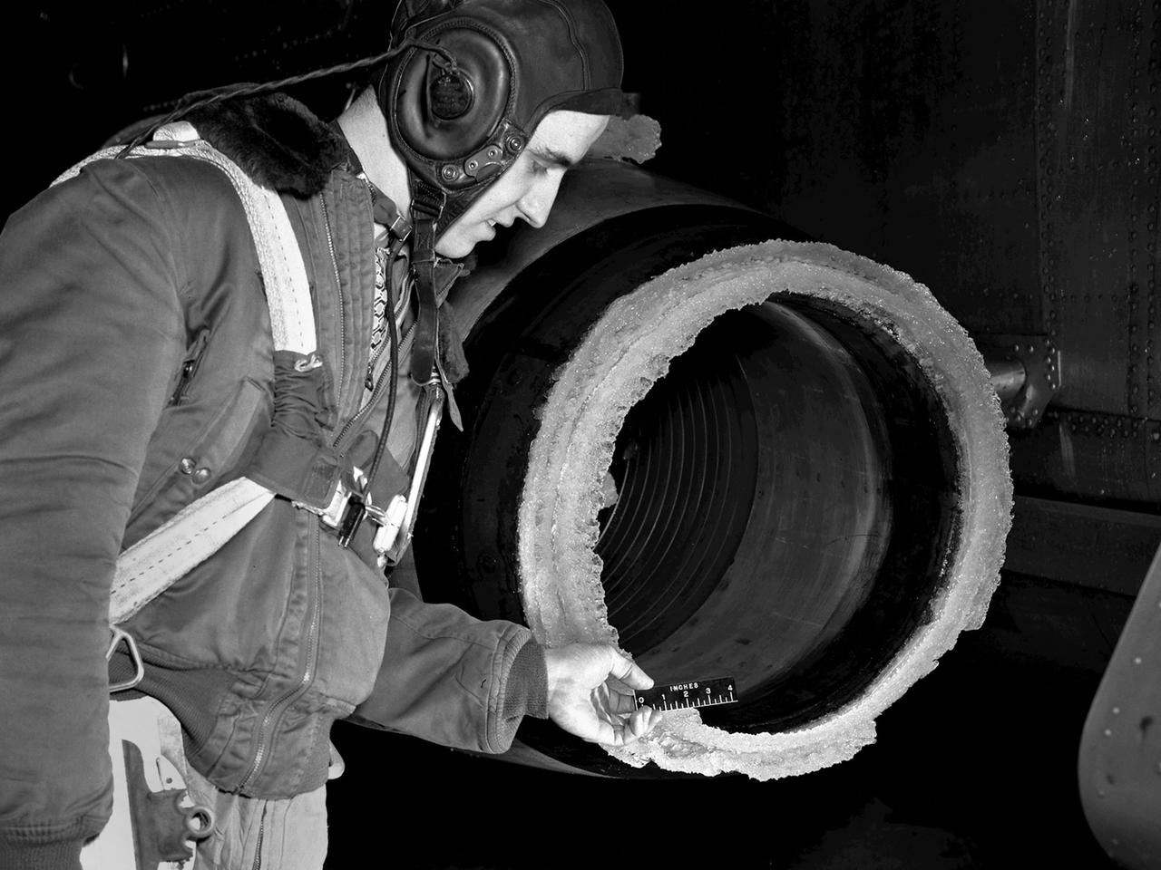
A National Advisory Committee for Aeronautics (NACA) researcher measures the ice thickness on a landing antenna model in the Icing Research Tunnel at the Aircraft Engine Research Laboratory. NACA design engineers added the Icing Research Tunnel to the original layout of the new Aircraft Engine Research Laboratory to take advantage of the massive refrigeration system being built for the Altitude Wind Tunnel. The Icing Research Tunnel was built to study the formation of ice on aircraft surfaces and methods of preventing or eradicating that ice. Ice buildup adds extra weight, effects aerodynamics, and sometimes blocks air flow through engines. The Icing Research Tunnel is a closed-loop atmospheric wind tunnel with a 6- by 9-foot test section. Carrier Corporation refrigeration equipment reduced the internal air temperature to -45 degrees F and a spray bar system injected water droplets into the air stream. The 24-foot diameter drive fan, seen in this photograph, created air flows velocities up to 400 miles per hour. The Icing Research Tunnel began testing in June of 1944. Early testing, seen in this photograph, studied ice accumulation on propellers and antenna of a military aircraft. The Icing Research Tunnel’s designers, however, struggled to develop a realistic spray system since they did not have access to data on the size of naturally occurring water droplets. The system would have to generate small droplets, distribute them uniformly throughout the airstream, and resist freezing and blockage. For five years a variety of different designs were painstakingly developed and tested before the system was perfected.
The US Air Force loaned a Republic F-84 Thunderjet to the National Advisory Committee for Aeronautics (NACA) Lewis Flight Propulsion Laboratory in the spring of 1954. NACA researchers soon modified the aircraft for the first demonstration of a reverse thruster. Republic built over 4000 Thunderjets between 1947 and 1953 for the military as a successor to the Lockheed F-80 Shooting Star. TheF-84s became successful multi-use aircraft during the Korean War. The use of traditional wheel brakes on high speed aircraft was problematic because the required braking system would weigh too much. The reverse thruster was developed as a method for stopping these aircraft without increasing the overall weight. Panels in the tail section near the jet engine’s nozzle opened up during a landing. These extended flaps not only caused resistance to the airstream but also reversed the engine’s thrust. In June 1964 Irving Pinkel, head of the Lewis Physics Division, oversaw a demonstration of this technology on an F-84 at the NACA laboratory. The side fuselage panels around the engine nozzle, seen closed in this photograph, opened up like wings and deflected the engine’s thrust towards the front of the aircraft, thus producing reverse thrust. The F-84 activated the reverse thruster and the aircraft moved backwards across the runway.
The National Advisory Committee for Aeronautics (NACA) Lewis Flight Propulsion Laboratory conducted an extensive icing research program in the late 1940s that included studies in the Icing Research Tunnel and using specially modified aircraft. One facet of this program was the investigation of the effects of icing on turbojets. Although jet engines allowed aircraft to pass through inclement weather at high rates of speed, ice accumulation was still a concern. The NACA’s B-24M Liberator was initially reconfigured with a General Electric I-16 engine installed in the aircraft’s waist compartment with an air scoop and spray nozzles to produce the artificial icing conditions. The centrifugal engine appeared nearly impervious to the effects of icing. Axial-flow jet engines, however, were much more susceptible to icing damage. The inlet guide vanes were particularly vulnerable, but the cowling’s leading edge, the main bearing supports, and accessory housing could also ice up. If pieces of ice reached the engine’s internal components, the compressor blades could be damaged. To study this phenomenon, a Westinghouse 24C turbojet, seen in this photograph, was installed under the B-24M’s right wing. In January 1948 flight tests of the 24C in icing conditions began. Despite ice buildup into the second stage of the compressor, the engine was able to operate at takeoff speeds. Researchers found the ice on the inlet vanes resulted in half of the engine’s decreased performance.
A Highly Maneuverable Aircraft Technology (HiMAT) inlet model installed in the test section of the 8- by 6-Foot Supersonic Wind Tunnel at the National Aeronautics and Space Administration (NASA) Lewis Research Center. Engineers at the Ames Research Center, Dryden Flight Research Center, and Rockwell International designed two pilotless subscale HiMAT vehicles in the mid-1970s to study new design concepts for fighter aircraft in the transonic realm without risking the lives of test pilots. The aircraft used sophisticated technologies such as advanced aerodynamics, composite materials, digital integrated propulsion control, and digital fly-by-wire control systems. In late 1977 NASA Lewis studied the HiMAT’s General Electric J85-21 jet engine in the Propulsion Systems Laboratory. The researchers charted the inlet quality with various combinations anti-distortion screens. HiMAT employed a relatively short and curved inlet compared to actual fighter jets. In the spring of 1979, Larry Smith led an in-depth analysis of the HiMAT inlet in the 8- by 6 tunnel. The researchers installed vortex generators to battle flow separation in the diffuser. The two HiMAT aircraft performed 11 hours of flying over the course of 26 missions from mid-1979 to January 1983 at Dryden and Ames. Although the HiMAT vehicles were considered to be overly complex and expensive, the program yielded a wealth of data that would validate computer-based design tools.
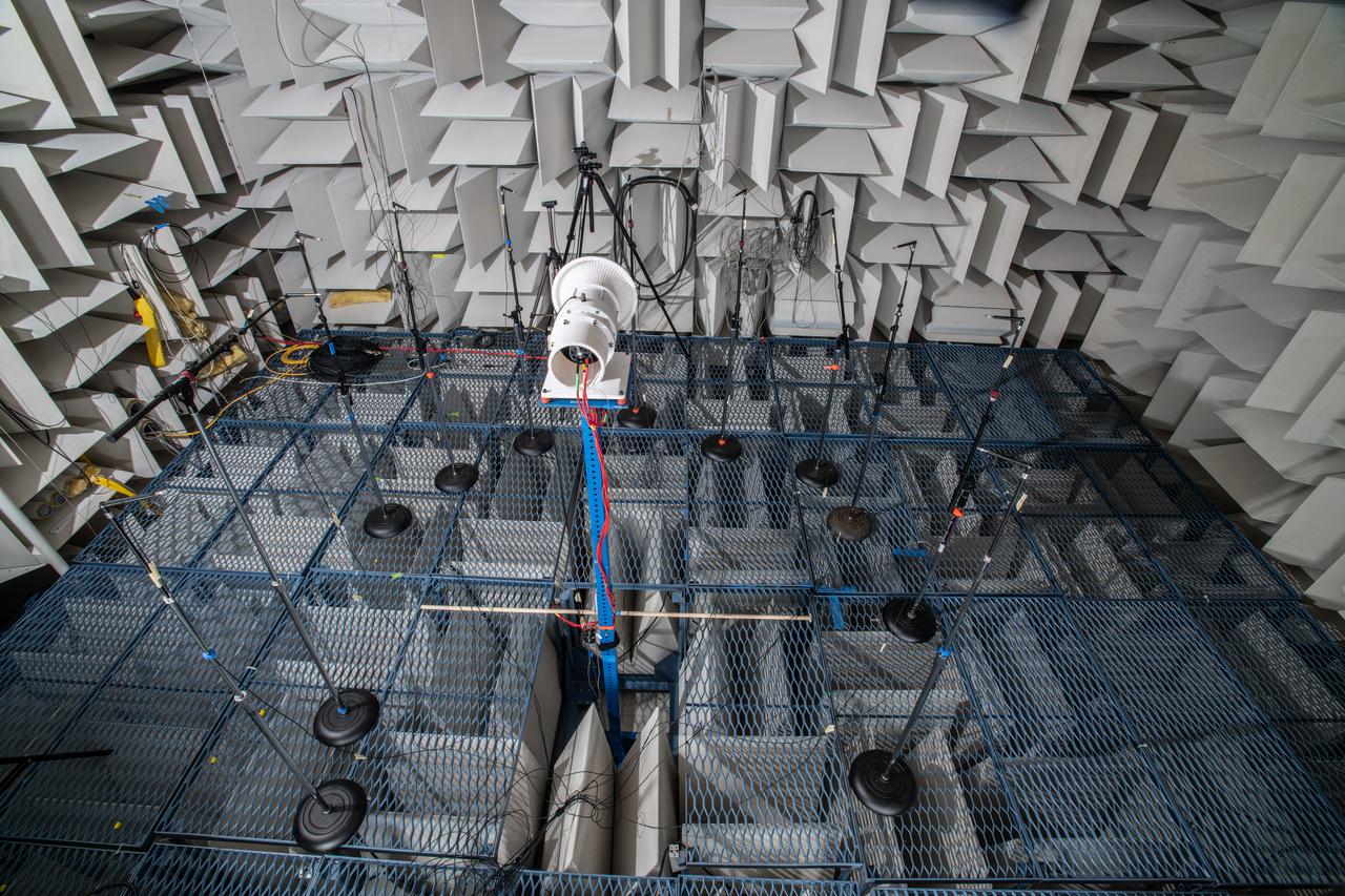
The Quiet Electric Engine V1 (QUEEN V1) experiment that was performed in the NASA GRC Acoustical Testing Laboratory (ATL). Equipment is installed in the anechoic chamber and in the adjacent control room. In response to the pervasive health and environmental problems associated with aviation noise and air pollution, NASA’s Quiet Electric Engine (QUEEN) team is working to increase the peace and quiet in the world by researching ways to make engines for large single-aisle aircraft safer, cleaner, and quieter.

The Quiet Electric Engine V1 (QUEEN V1) experiment that was performed in the NASA GRC Acoustical Testing Laboratory (ATL). Equipment is installed in the anechoic chamber and in the adjacent control room. In response to the pervasive health and environmental problems associated with aviation noise and air pollution, NASA’s Quiet Electric Engine (QUEEN) team is working to increase the peace and quiet in the world by researching ways to make engines for large single-aisle aircraft safer, cleaner, and quieter.
The Quiet Electric Engine V1 (QUEEN V1) experiment that was performed in the NASA GRC Acoustical Testing Laboratory (ATL). Equipment is installed in the anechoic chamber and in the adjacent control room. In response to the pervasive health and environmental problems associated with aviation noise and air pollution, NASA’s Quiet Electric Engine (QUEEN) team is working to increase the peace and quiet in the world by researching ways to make engines for large single-aisle aircraft safer, cleaner, and quieter.
The Quiet Electric Engine V1 (QUEEN V1) experiment that was performed in the NASA GRC Acoustical Testing Laboratory (ATL). Equipment is installed in the anechoic chamber and in the adjacent control room. In response to the pervasive health and environmental problems associated with aviation noise and air pollution, NASA’s Quiet Electric Engine (QUEEN) team is working to increase the peace and quiet in the world by researching ways to make engines for large single-aisle aircraft safer, cleaner, and quieter.
The Quiet Electric Engine V1 (QUEEN V1) experiment that was performed in the NASA GRC Acoustical Testing Laboratory (ATL). Equipment is installed in the anechoic chamber and in the adjacent control room. In response to the pervasive health and environmental problems associated with aviation noise and air pollution, NASA’s Quiet Electric Engine (QUEEN) team is working to increase the peace and quiet in the world by researching ways to make engines for large single-aisle aircraft safer, cleaner, and quieter.
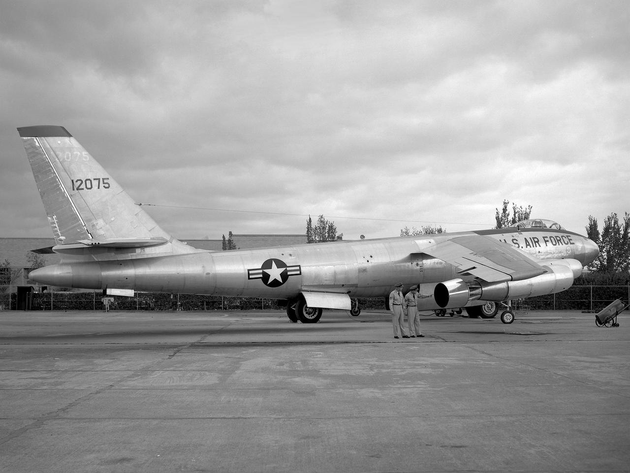
A Boeing B-47 Stratojet bomber with a noise-reducing ejector on its engine at the 1957 Inspection of the National Advisory Committee for Aeronautics (NACA) Lewis Flight Propulsion Laboratory. Representatives from the military, aeronautical industry, universities, and the press were invited to the laboratory to be briefed on the NACA’s latest research efforts and tour the state- of- the- art test facilities. Over 1700 people visited the NACA Lewis in Cleveland, Ohio during October 7 - 10, 1957. By the mid-1950s, the aircraft industry was close to introducing jet airliners to the nation’s airways. The noise produced by the large jet engines, however, would pose a considerable problem for communities near airports. This problem was demonstrated at the 1957 Inspection by an NACA Lewis researcher who played longplay (LP) audio records of military jet engines for an audience. Tests showed that the source of the loudest noise was not the engine itself, but the mixing of the engine’s exhaust with the surrounding air in the atmosphere. The pressures resulting from this turbulence produced sound waves. One of Lewis’ first studies sought to design an exhaust nozzle that reduced the turbulence. A Pratt and Whitney J57 was tested in the Altitude Wind Tunnel with many of these nozzle configurations from January to May 1957. Researchers found that the various nozzle types did reduce the noise levels but also reduced the aircraft’s thrust. Afterwards, they determined that the addition of an NACA-developed ejector reduced the noise levels without diminishing thrust.
Construction Manager Raymond Sharp and the National Advisory Committee for Aeronautics (NACA) Director of Research George Lewis speak to employees during the May 8, 1942, Initiation of Research ceremony at the Aircraft Engine Research Laboratory. The event marked the first operation of a test facility at the new laboratory. The overall laboratory was still under construction, however, and behind schedule. Lewis traveled from his office in Washington, DC every week to personally assess the progress. Drastic measures were undertaken to accelerate the lab’s construction schedule. The military provided special supplies, contractors were given new agreements and pressured to meet deadlines, and Congress approved additional funds. The effort paid off and much of the laboratory was operational in early 1943. George Lewis managed the NACA’s aeronautical research for over 20 years. Lewis joined the NACA as Executive Officer in 1919, and was named Director of Aeronautical Research in 1924. In this role Lewis served as the liaison between the Executive Committee and the research laboratories. His most important accomplishment may have been the investigative tours of the research facilities in Germany in 1936 and 1939. The visits resulted in the NACA’s physical expansion and the broadening of the scope of its research. Lewis did not take a day of leave between the Pearl Harbor attack and the Armistice. He began suffering health problems in 1945 and was forced to retire two years later. The Aircraft Engine Research Laboratory was renamed the NACA Lewis Flight Propulsion Laboratory in September 1948.
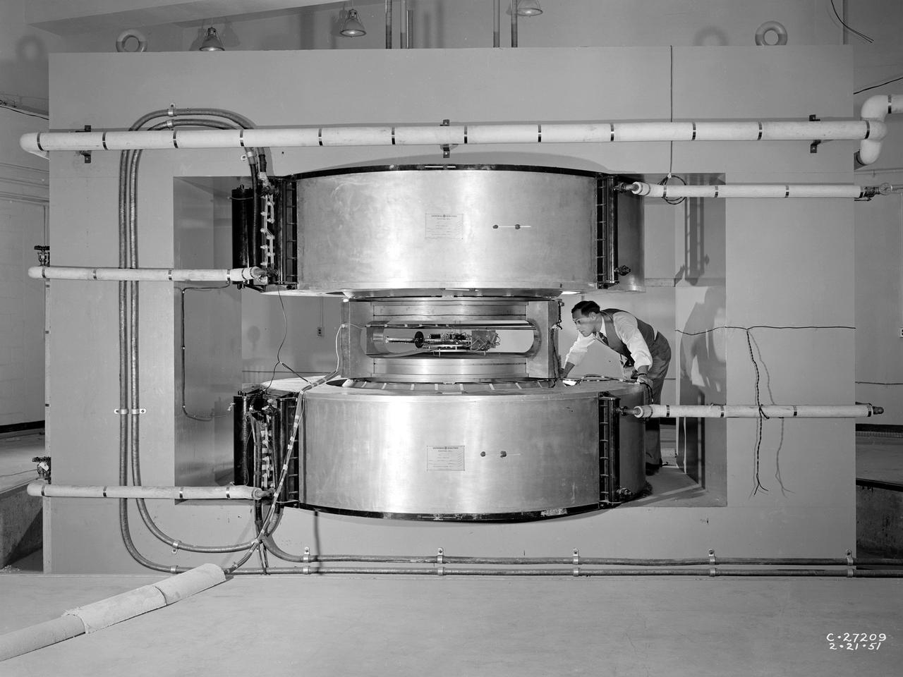
Researcher James Blue examines the new cyclotron at the National Advisory Committee for Aeronautics (NACA) Lewis Flight Propulsion Laboratory. Researchers at NACA Lewis began postulating about the use of atomic power for propulsion immediately after World War II. The NACA concentrated its efforts on the study of high temperature materials and heat transfer since it did not have access to the top secret fission information. The military studied the plausibility of nuclear propulsion for aircraft in the late 1940s. The military program was cancelled after four years without any breakthroughs, but the Atomic Energy Commission took on the effort in 1951. The NACA Lewis laboratory was expanding its nuclear-related research during this period. In 1948, Lewis engineers were assigned to the Oak Ridge National Laboratory to obtain expertise in high temperature heat transfer and advanced materials technology. The following year a new 80-person Nuclear Reactor Division was created, and an in-house nuclear school was established to train these researchers. The cyclotron was built behind the Materials and Structures Laboratory to support thermodynamic and materials research for both nuclear aircraft and nuclear rockets. The original NACA Lewis cyclotron was used to accelerate two kinds of particles. To better match the space radiation environment, the cyclotron was later modified to accelerate particles of the newly-discovered Van Allen radiation belts.

One of many safety posters produced by NACA artists during World War II. The Aircraft Engine Research Laboratory established a Safety Office in 1942 to coordinate and oversee safety-related activities. The lab struggled to maintain a full staff during the war when military research projects were at a peak. NACA management mandated six-day work weeks without overtime and the elimination of holidays. As such, workplace injuries were a serious threat to maintaining productivity needed to sustain the military’s aeronautics efforts.

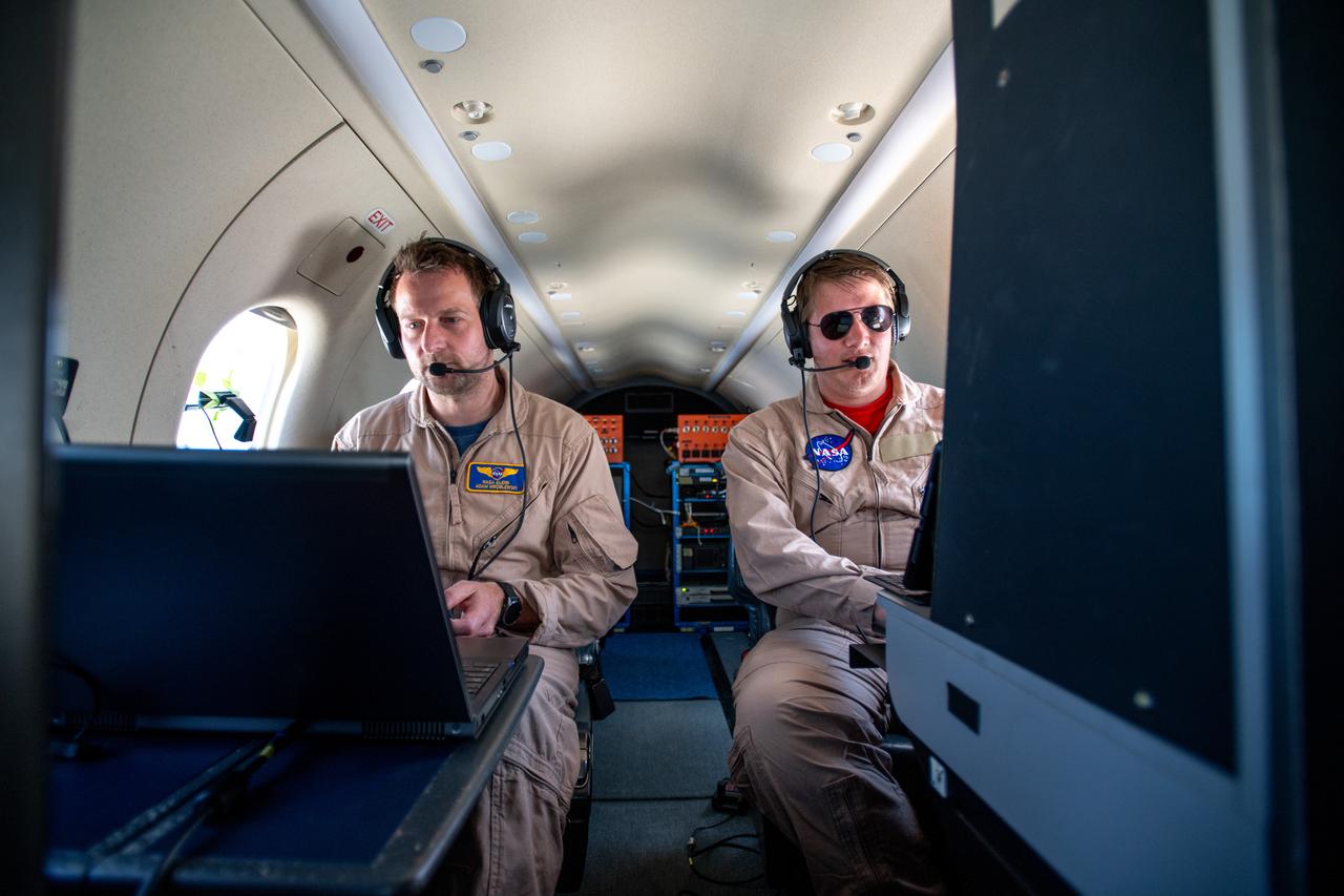
A team at NASA’s Glenn Research Center in Cleveland streamed 4K video footage from an aircraft to the International Space Station and back for the first time using optical, or laser, communications. The feat was part of a series of tests on new technology that could provide live video coverage of astronauts on the Moon during the Artemis missions. Pictured from Left to Right: James Demers, Adam Wroblewski, Shaun McKeehan, Kurt Blankenship. Working with the Air Force Research Laboratory and NASA’s Small Business Innovation Research program, Glenn engineers temporarily installed a portable laser terminal on the belly of a Pilatus PC-12 aircraft. They then flew over Lake Erie sending data from the aircraft to an optical ground station in Cleveland. From there, it was sent over an Earth-based network to NASA’s White Sands Test Facility in Las Cruces, New Mexico, where scientists used infrared light signals to send the data.
A team at NASA’s Glenn Research Center in Cleveland streamed 4K video footage from an aircraft to the International Space Station and back for the first time using optical, or laser, communications. The feat was part of a series of tests on new technology that could provide live video coverage of astronauts on the Moon during the Artemis missions. Working with the Air Force Research Laboratory and NASA’s Small Business Innovation Research program, Glenn engineers temporarily installed a portable laser terminal on the belly of a Pilatus PC-12 aircraft. They then flew over Lake Erie sending data from the aircraft to an optical ground station in Cleveland. From there, it was sent over an Earth-based network to NASA’s White Sands Test Facility in Las Cruces, New Mexico, where scientists used infrared light signals to send the data.
A team at NASA’s Glenn Research Center in Cleveland streamed 4K video footage from an aircraft to the International Space Station and back for the first time using optical, or laser, communications. The feat was part of a series of tests on new technology that could provide live video coverage of astronauts on the Moon during the Artemis missions. Working with the Air Force Research Laboratory and NASA’s Small Business Innovation Research program, Glenn engineers temporarily installed a portable laser terminal on the belly of a Pilatus PC-12 aircraft. They then flew over Lake Erie sending data from the aircraft to an optical ground station in Cleveland. From there, it was sent over an Earth-based network to NASA’s White Sands Test Facility in Las Cruces, New Mexico, where scientists used infrared light signals to send the data.
A team at NASA’s Glenn Research Center in Cleveland streamed 4K video footage from an aircraft to the International Space Station and back for the first time using optical, or laser, communications. The feat was part of a series of tests on new technology that could provide live video coverage of astronauts on the Moon during the Artemis missions. Working with the Air Force Research Laboratory and NASA’s Small Business Innovation Research program, Glenn engineers temporarily installed a portable laser terminal on the belly of a Pilatus PC-12 aircraft. They then flew over Lake Erie sending data from the aircraft to an optical ground station in Cleveland. From there, it was sent over an Earth-based network to NASA’s White Sands Test Facility in Las Cruces, New Mexico, where scientists used infrared light signals to send the data.

A team at NASA’s Glenn Research Center in Cleveland streamed 4K video footage from an aircraft to the International Space Station and back for the first time using optical, or laser, communications. The feat was part of a series of tests on new technology that could provide live video coverage of astronauts on the Moon during the Artemis missions. Working with the Air Force Research Laboratory and NASA’s Small Business Innovation Research program, Glenn engineers temporarily installed a portable laser terminal on the belly of a Pilatus PC-12 aircraft. They then flew over Lake Erie sending data from the aircraft to an optical ground station in Cleveland. From there, it was sent over an Earth-based network to NASA’s White Sands Test Facility in Las Cruces, New Mexico, where scientists used infrared light signals to send the data.

A team at NASA’s Glenn Research Center in Cleveland streamed 4K video footage from an aircraft to the International Space Station and back for the first time using optical, or laser, communications. The feat was part of a series of tests on new technology that could provide live video coverage of astronauts on the Moon during the Artemis missions. Working with the Air Force Research Laboratory and NASA’s Small Business Innovation Research program, Glenn engineers temporarily installed a portable laser terminal on the belly of a Pilatus PC-12 aircraft. They then flew over Lake Erie sending data from the aircraft to an optical ground station in Cleveland. From there, it was sent over an Earth-based network to NASA’s White Sands Test Facility in Las Cruces, New Mexico, where scientists used infrared light signals to send the data. Photo Credit: (NASA/Sara Lowthian-Hanna)
A team at NASA’s Glenn Research Center in Cleveland streamed 4K video footage from an aircraft to the International Space Station and back for the first time using optical, or laser, communications. The feat was part of a series of tests on new technology that could provide live video coverage of astronauts on the Moon during the Artemis missions. Working with the Air Force Research Laboratory and NASA’s Small Business Innovation Research program, Glenn engineers temporarily installed a portable laser terminal on the belly of a Pilatus PC-12 aircraft. They then flew over Lake Erie sending data from the aircraft to an optical ground station in Cleveland. From there, it was sent over an Earth-based network to NASA’s White Sands Test Facility in Las Cruces, New Mexico, where scientists used infrared light signals to send the data. Photo Credit: (NASA/Sara Lowthian-Hanna)
A team at NASA’s Glenn Research Center in Cleveland streamed 4K video footage from an aircraft to the International Space Station and back for the first time using optical, or laser, communications. The feat was part of a series of tests on new technology that could provide live video coverage of astronauts on the Moon during the Artemis missions. Working with the Air Force Research Laboratory and NASA’s Small Business Innovation Research program, Glenn engineers temporarily installed a portable laser terminal on the belly of a Pilatus PC-12 aircraft. They then flew over Lake Erie sending data from the aircraft to an optical ground station in Cleveland. From there, it was sent over an Earth-based network to NASA’s White Sands Test Facility in Las Cruces, New Mexico, where scientists used infrared light signals to send the data.
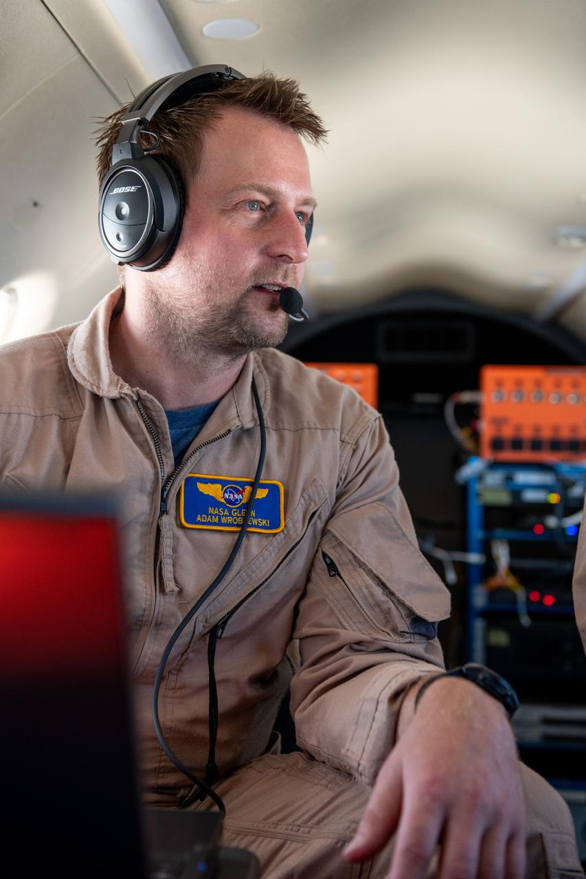
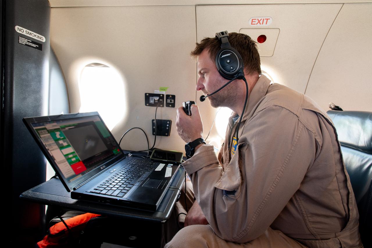
Adam Wroblewski p A team at NASA’s Glenn Research Center in Cleveland streamed 4K video footage from an aircraft to the International Space Station and back for the first time using optical, or laser, communications. The feat was part of a series of tests on new technology that could provide live video coverage of astronauts on the Moon during the Artemis missions. Working with the Air Force Research Laboratory and NASA’s Small Business Innovation Research program, Glenn engineers temporarily installed a portable laser terminal on the belly of a Pilatus PC-12 aircraft. Adam Wroblewski in the PC-12 over Lake Erie on June 13, 2024 sending data from the aircraft to an optical ground station in Cleveland. From there, it was sent over an Earth-based network to NASA’s White Sands Test Facility in Las Cruces, New Mexico, where scientists used infrared light signals to send the data. Photo Credit: (NASA/Sara Lowthian-Hanna)
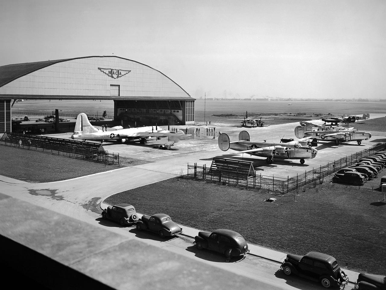
This fleet of military aircraft was used in the 1940s for research at the National Advisory Committee for Aeronautics (NACA) Lewis Flight Propulsion Laboratory in Cleveland, Ohio. The NACA Lewis flight research program was established in March 1943 to augment the lab’s wartime research efforts. NACA Lewis possessed a host of wind tunnels, test stands, and other ground facilities designed to replicate flight conditions, but actual flight tests remained an integral research tool. The military loaned NACA Lewis 15 different aircraft during World War II and six others in the six months following the end of hostilities. During the war these aircraft supported three main efforts: the improved performance of reciprocating engines, better fuel additives and mixtures, and deicing systems. The wartime researchers used the types of aircraft which the studies were intended to improve. After the war the research aircraft served as test beds to investigate engines or systems that often had little to do with the research aircraft. During the war, NACA Lewis’ three pilots were supported by 16 flight engineers, 36 mechanics, and 10 instrumentation specialists. The visible aircraft, from left to right, are a Boeing B-29 Superfortress, a Martin B-26A Marauder, two Consolidated B-24 Liberators, a Cessna UC-78 Bobcat, and a Northrop P-61 Black Widow. Partially obscured are a North American P-51 Mustang, a Bell P-63 King Cobra, a North American AT-6 Texan, and a Lockheed RA-29 Hudson.
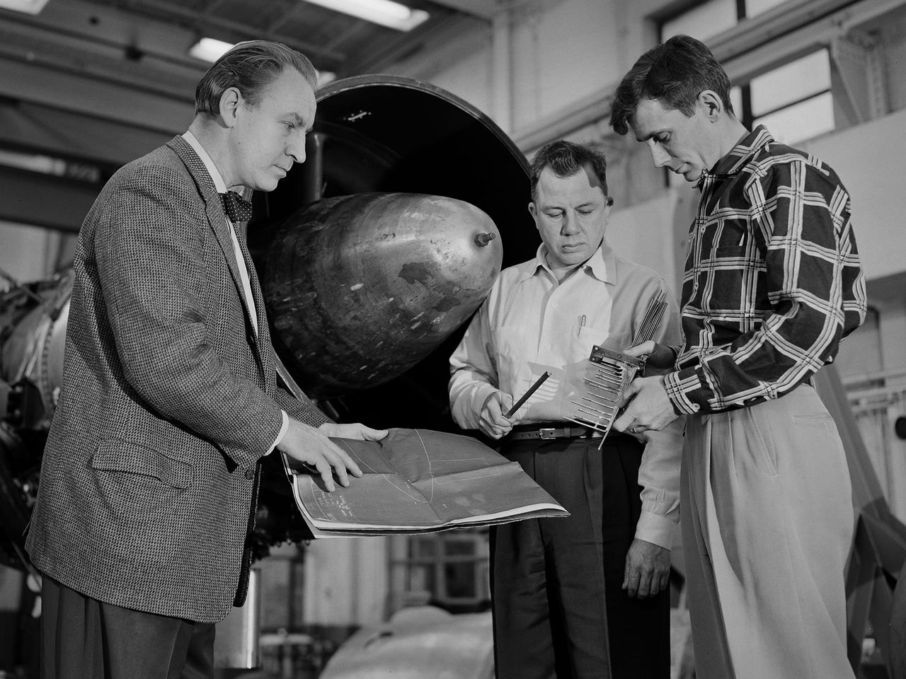
Researcher Bill Reiwaldt discusses the preparations for a test in the Altitude Wind Tunnel with technicians Jack Wagner and Dick Golladay at the National Advisory Committee for Aeronautics (NACA) Lewis Flight Propulsion Laboratory. Research engineers developed ideas for tests that were often in response to requests from the military or aircraft industry. Arrangements were made to obtain an engine for the study and to transport it to the Cleveland laboratory. The engine was brought into the facility’s shop area, where it was readied for investigation. It was common for several different engines to be worked on simultaneously in the shop. The researcher would discuss the engine and the test objectives with the Test Installation Division and the facility’s technicians. The operations team would handle the installation of the instrumentation and fitting the test into the facility’s schedule. Upon completion of the previous test, the engine was removed. The next engine was lifted by an overhead crane and transported from the shop to the test section. The engine was connected to the measurement devices and fuel and oil supply lines. Engines were tested over numerous runs under varying conditions and with variations on the configuration. The findings and test procedure were then described in research or technical memorandums and distributed to industry.
A researcher examines a model being installed in the test section of the 10- by 10-Foot Supersonic Wind Tunnel during the 1957 Inspection of the National Advisory Committee for Aeronautics (NACA) Lewis Flight Propulsion Laboratory. The NACA held its annual Inspection at one of its three research laboratories. Representatives from the military, aeronautical industry, universities, and the press were invited to the laboratory to be briefed on the NACA’s latest research efforts and tour the state- of- the- art test facilities. Over 1700 people visited the NACA Lewis in Cleveland, Ohio during the October 7 - 10, 1957 Inspection. NACA researchers Leonard Obery, seen here, James Connors, Leonard, Stitt, David Bowditch gave presentations on high Mach number turbojets at the 10- by 10 tunnel. It had been only 15 years since a jet aircraft had first flown in the US. Since then the sound barrier had been broken and speeds of Mach 2.5 had been achieved. In the late 1950s NACA researchers sought to create an engine that could achieve Mach 4. This type of engine would require an extremely long inlet and nozzle which would have to be capable of adjusting their diameter for different speeds. A Mach 4 engine would require new composite materials to withstand the severe conditions, modified airframes to hold the longer engines, and high temperature seals and lubricants. The 10- by 10-foot tunnel, which had only been in operation for a year and a half, would play a critical role in these studies. NACA researchers at other facilities discussed high energy aircraft fuels and rocket propellants, aircraft noise reduction, hypersonic flight, nuclear propulsion, and high temperature materials.
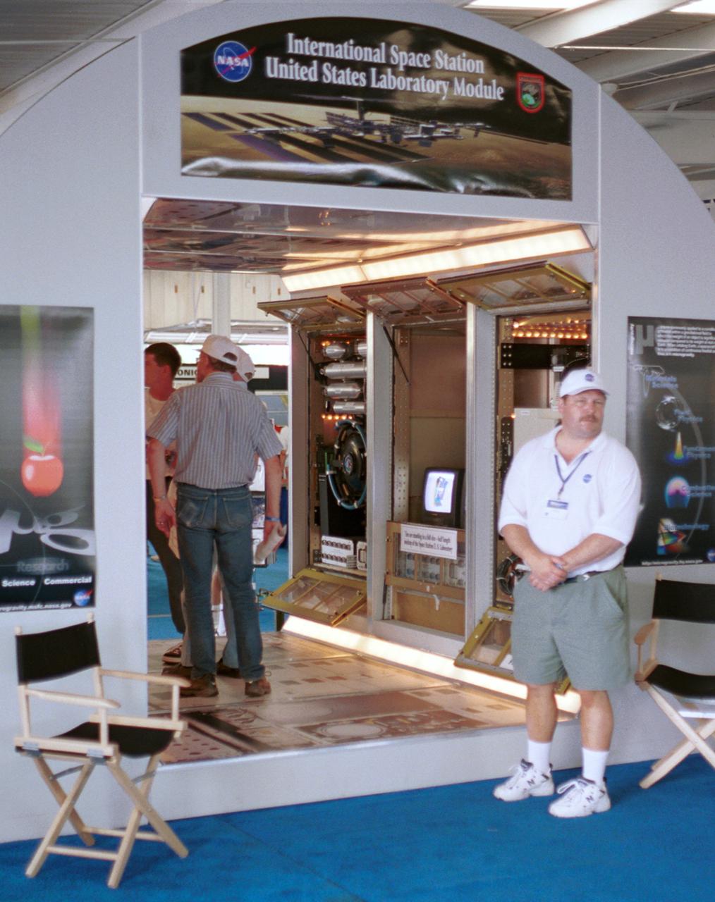
Thomas Turk, an engineer with NASA's Glenn Research Center, waits for more visitors at a mockup of part of Destiny, the U.S. laboratory module that will be attached to the International Space Station (ISS) in Year 2001. Visible behind Turk are engineering models of the three racks that will make up the Fluids and Combustion Facility (FCF) in the module. The mockup is full scale, although Destiny will be twice as long to accomodate six experiment racks along each side. The exhibit was part of the NASA outreach activity at AirVenture 2000 sponsored by the Expeprimental Aircraft Association in Oshkosh, WI.
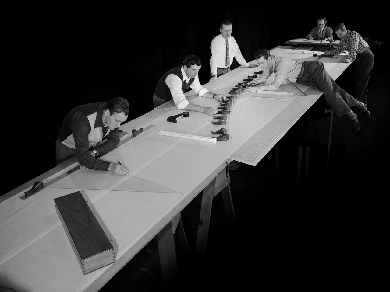
Draftsmen in the Materials and Stresses Building at the National Advisory Committee for Aeronautics (NACA) Lewis Flight Propulsion Laboratory create a template for a compressor using actual compressor blades. The Compressor and Turbine Division contained four sections of researchers dedicated to creating better engine components. The Materials and Thermodynamics Division studied the strength, durability, heat transfer characteristics, and physical composition of various materials. The two divisions were important to the research and development of new aircraft engines. The constant battle to increase the engine’s thrust while decreasing its overall weight resulted in additional stress on jet engine components, particularly compressors. As speed and maneuverability were enhanced, the strain on the engines and inlets grew. For decades NACA Lewis researchers continually sought to improve compressor blade design, develop stronger composite materials, and minimize flutter and inlet distortions.
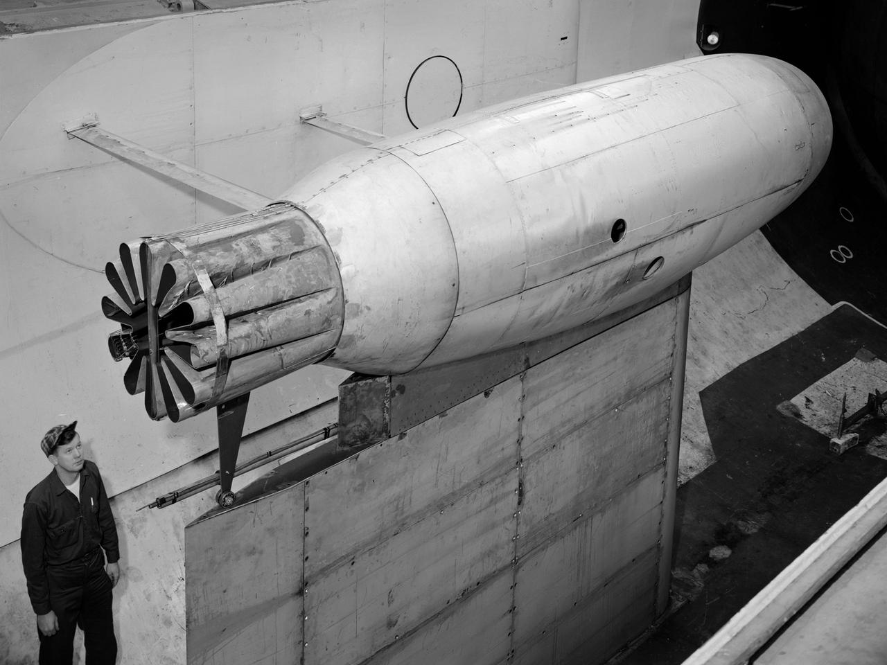
A Pratt and Whitney J57 engine is tested with a Greatex No.1 nozzle in the Altitude Wind Tunnel at the National Advisory Committee for Aeronautics (NACA) Lewis Flight Propulsion Laboratory. At the time the aircraft industry was preparing to introduce jet airliners to the nation’s airways. The noise produced by the large jet engines, however, posed a considerable problem for communities near airports. The NACA had formed a Special Subcommittee on Aircraft Noise to coordinate research on the issue. Preliminary tests showed that the source of the loudest noise was not the engine itself, but the mixing of the engine’s exhaust with the surrounding air in the atmosphere. The pressures resulting from this turbulence produced sound waves. Lewis researchers undertook a variety of noise-reduction studies involving engine design, throttling procedures, and noise suppressors. One of their first efforts focused on new types of nozzles to mix the exhaust with the surrounding air. The nozzles had a variety of shapes designed to slow down exhaust velocity before it combined with the air and thus decrease the noise. From January to May 1957 a Pratt and Whitney J57 engine was equipped with various shaped nozzles, as seen in this photograph, and run in simulated flight conditions in the Altitude Wind Tunnel. A number of nozzle configurations, including several multi-exit “organ pipe” designs, were created. It was found that the various nozzle types did reduce the noise levels, but they also reduced the aircraft’s thrust.
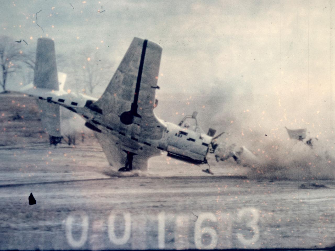
Researchers at the National Advisory Committee for Aeronautics (NACA) Lewis Flight Propulsion Laboratory purposely wreck a McDonnell FH-1 Phantom as part of the laboratory’s Crash Fire Program. NACA Lewis researchers created the program in 1949 to investigate methods for improving survival rates for take-off and landing-type crashes. In these types of crashes, the passengers often survived the impact only to perish in the ensuing fire. Previously there had been little information on the nature of post-crash fires, and it was difficult to use analytical studies in this area. Irving Pinkel, Chief of the Lewis Flight Propulsion Division, was the primary researcher. He enlisted flight safety specialist and aeronautics researchers G. Merritt Preston and Gerard Pesman, mechanical engineer Dugald Black, and others. The tests were conducted at the nearby Ravenna Arsenal using decommissioned Air Force fighter and transport aircraft. The pilotless aircraft were accelerated down a rail on a 1700-foot track at take-off speeds and run into barriers to simulate a variety of different types of crashes. The first barrier stripped off the landing gears and another briefly sent the aircraft off the ground before it crashed into a dirt mound. Telemetry and high-speed cameras were crucial elements in these studies. NACA Lewis photographer Bill Wynne developed a method for inserting timekeeping devices on test film that were able to show time to one thousandth of a second.
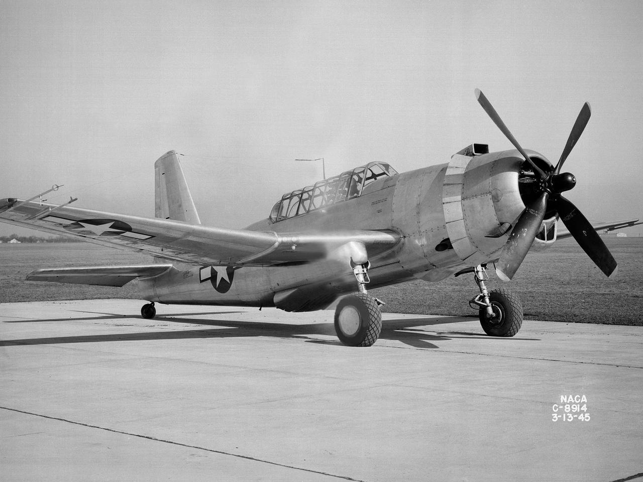
A Bell P-39 Airacobra in the NACA Aircraft Engine Research Laboratory’s Icing Research Tunnel for a propeller deicing study. The tunnel, which began operation in June 1944, was built to study the formation of ice on aircraft surfaces and methods of preventing or eradicating that ice. Ice buildup adds extra weight to aircraft, effects aerodynamics, and sometimes blocks airflow through engines. NACA design engineers added the Icing Research Tunnel to the new AERL’s original layout to take advantage of the massive refrigeration system being constructed for the Altitude Wind Tunnel. The Icing Research Tunnel is a closed-loop atmospheric wind tunnel with a 6- by 9-foot test section. The tunnel can produce speeds up to 300 miles per hour and temperatures from about 30 to -45⁰ F. During World War II AERL researchers analyzed different ice protection systems for propeller, engine inlets, antennae, and wings in the icing tunnel. The P-39 was a vital low-altitude pursuit aircraft of the US during the war. NACA investigators investigated several methods of preventing ice buildup on the P-39’s propeller, including the use of internal and external electrical heaters, alcohol, and hot gases. They found that continual heating of the blades expended more energy than the aircraft could supply, so studies focused on intermittent heating. The results of the wind tunnel investigations were then compared to actual flight tests on aircraft.
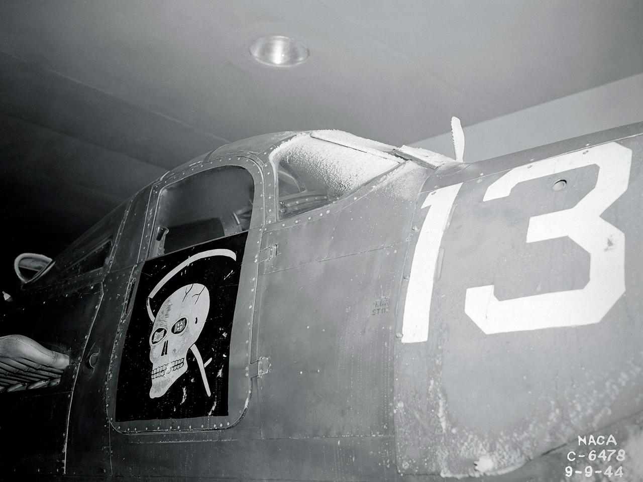
A Bell P-39 Airacobra in the NACA Aircraft Engine Research Laboratory’s Icing Research Tunnel for a propeller deicing study. The tunnel, which began operation in June 1944, was built to study the formation of ice on aircraft surfaces and methods of preventing or eradicating that ice. Ice buildup adds extra weight to aircraft, effects aerodynamics, and sometimes blocks airflow through engines. NACA design engineers added the Icing Research Tunnel to the new AERL’s original layout to take advantage of the massive refrigeration system being constructed for the Altitude Wind Tunnel. The Icing Research Tunnel is a closed-loop atmospheric wind tunnel with a 6- by 9-foot test section. The tunnel can produce speeds up to 300 miles per hour and temperatures from about 30 to –45⁰ F. During World War II AERL researchers analyzed different ice protection systems for propeller, engine inlets, antennae, and wings in the icing tunnel. The P-39 was a vital low-altitude pursuit aircraft of the US during the war. NACA investigators investigated several methods of preventing ice buildup on the P-39’s propeller, including the use of internal and external electrical heaters, alcohol, and hot gases. They found that continual heating of the blades expended more energy than the aircraft could supply, so studies focused on intermittent heating. The results of the wind tunnel investigations were then compared to actual flight tests on aircraft.
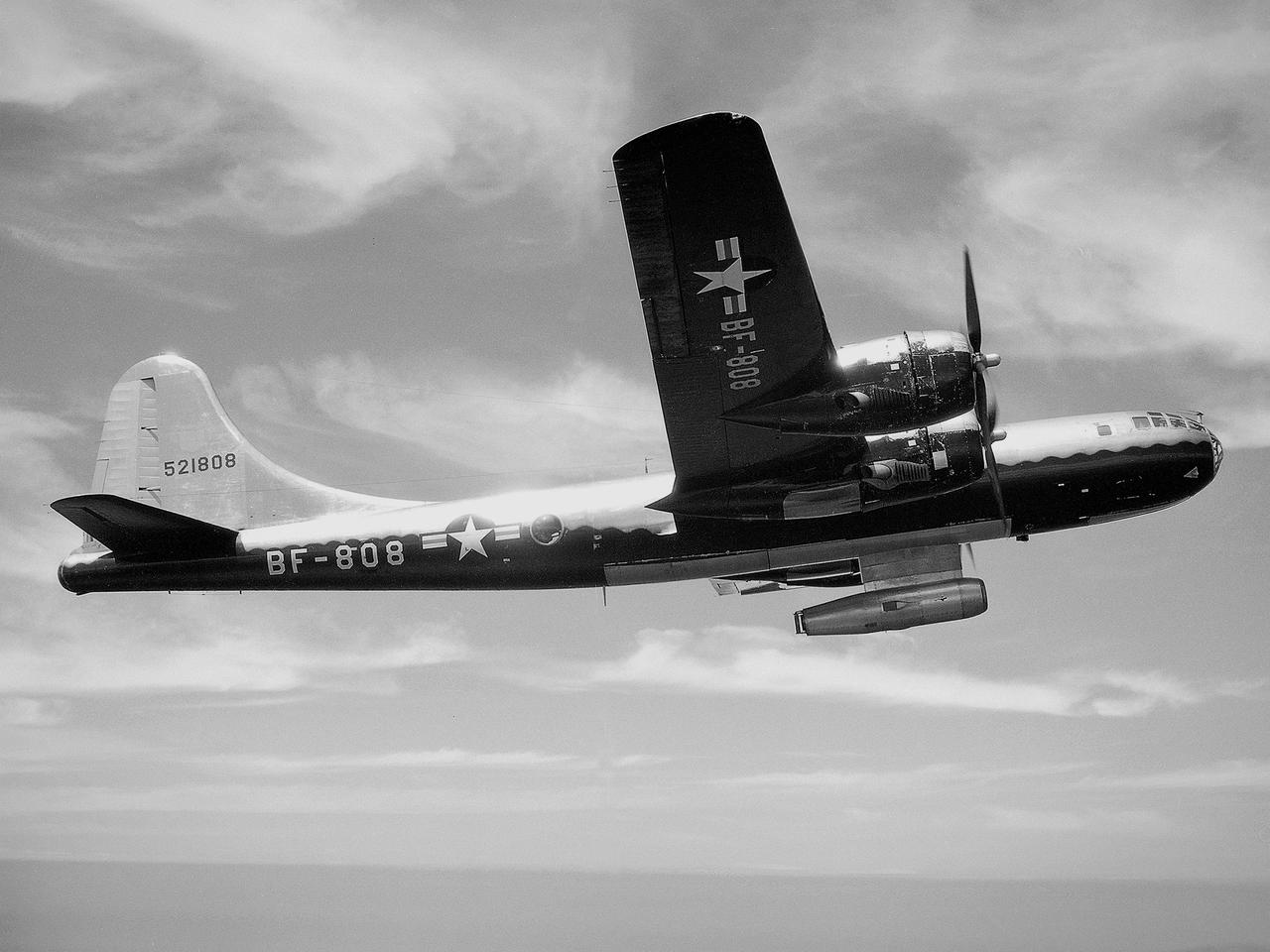
The NACA’s Lewis Flight Propulsion Laboratory used a Boeing B‒29 Superfortress as a testbed for ramjet investigations in the late 1940s. Lewis researchers conducted a wide variety of studies on ramjets to determine basic the operational data necessary to design missiles. Extensive wind tunnel and test stand studies were augmented by actual flight tests. Lewis engineers modified this B‒29 so that the ramjet could be stored in the bomb bay. Once the aircraft reached the desired altitude and speed, a mechanical arm suspended the ramjet 52 inches below the bomb bay. The ramjet’s angle-of-attack could be independently adjusted, and a periscope permitted a view of the test article from inside the aircraft. Researchers took measurements in free-stream conditions at speeds up to Mach 0.51 and at altitudes ranging from 5,000 to 30,000 feet. They then shut the ramjet down and retracted it into the aircraft. The researchers first determined that 14,000 feet was the maximum altitude at which the engine could be ignited by spark. They used flares to start the engine at altitudes up to 30,000 feet. They were able to determine maximum combustion efficiencies, response time to changes in fuel flow, and minimum fuel-air ratios. Overall the ramjet operated well at all speeds and altitudes.
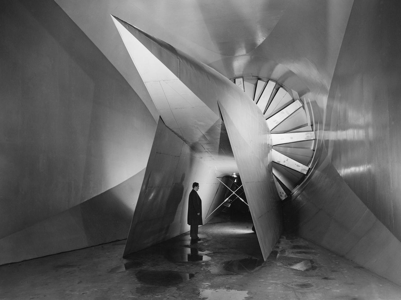
View of the drive fan for the Icing Research Tunnel at the National Advisory Committee for Aeronautics (NACA) Aircraft Engine Research Laboratory in Cleveland, Ohio. The tunnel was built in the early 1940s to study the formation of ice on aircraft surfaces and methods of preventing or eradicating that ice. Ice buildup adds extra weight, effects aerodynamics, and sometimes blocks airflow through engines. The original 4100-horsepower induction motor was coupled directly to the 24-foot-diameter fan. The 12 wooden fan blades were protected on their leading edge by a neoprene boot. The system could create air speeds up to 300 miles per hour through the tunnel’s 6- by 9-foot test section. The large tail faring extending from the center of the fan is used to guide the airflow down the tunnel in a uniform way. A new 5000-horsepower motor was installed in 1987, and the original fan blades were replaced in 1993.
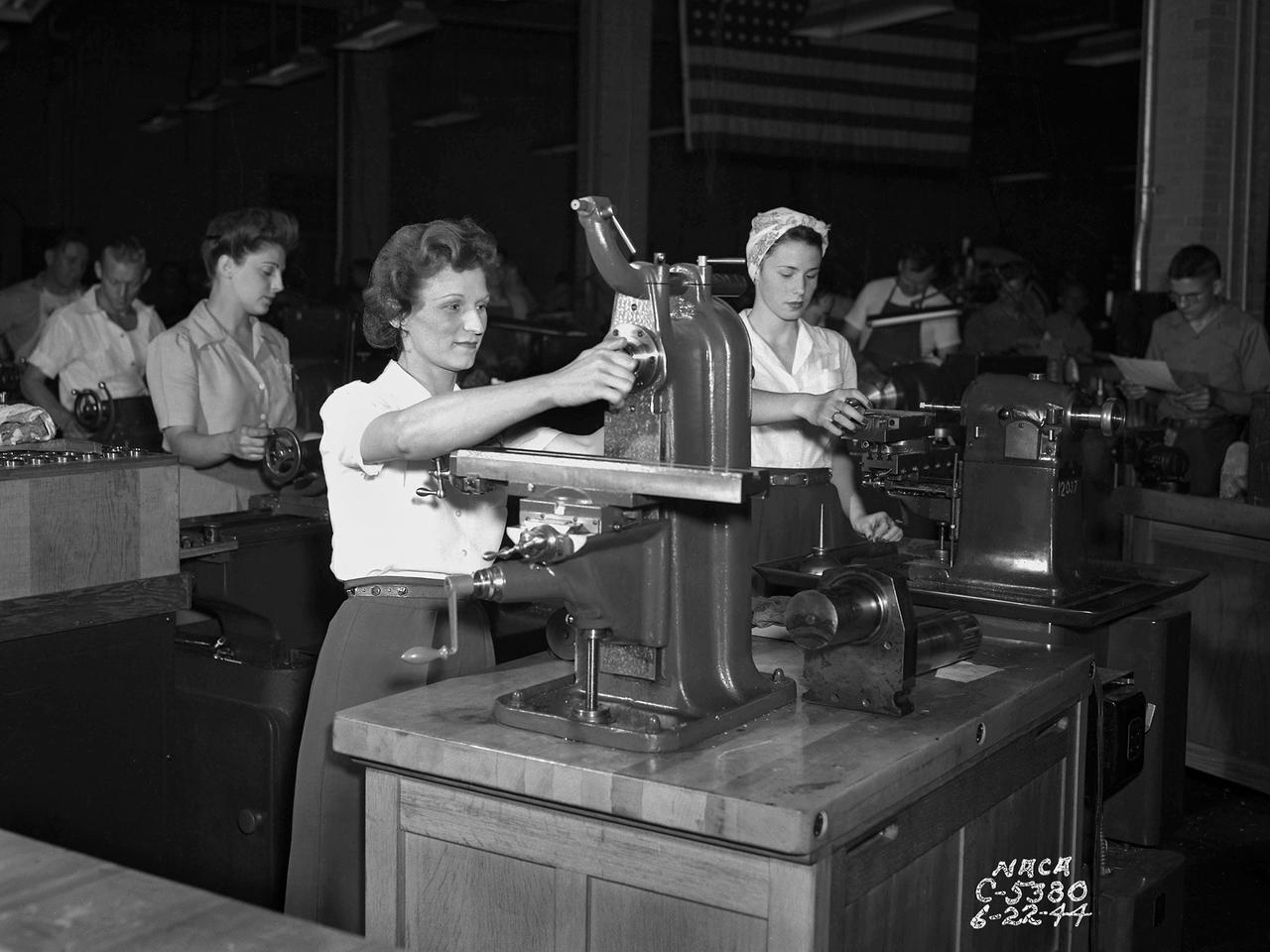
The loss of male NACA employees to the war effort and the military’s increased demand for expedited aeronautical research results resulted in a sharp demand for increased staffing in the early 1940s. The Aircraft Engine Research Laboratory (AERL) undertook an extensive recruiting effort to remedy the situation. Current employees were asked to bring in friends and family members, including women. The number of women employed at the AERL nearly doubled to 412 between 1943 and 1944. In May 1944 Director Raymond Sharp initiated a program to train women as machine operators, electricians, instrumentation engineers, and other technical positions. The move coincided with the lab’s implementation of a third shift to meet the military’s demands for improved aircraft performance. There was also a modest, but important, number of female engineers and chemists, as well as large group employed in more traditional positions such as data analysts, editors, and clerks. The integration of women in the research process was critical. Researchers developed a test and submitted plans to the Drafting Section to be converted into blueprints. In some instances the Instrumentation Shop was asked to create instruments for the test. During the test, computers gathered and analyzed the data. The researcher then wrote the report which was reviewed by the Editorial Department and printed in the Duplication Unit. All of these tasks were generally performed by female employees.
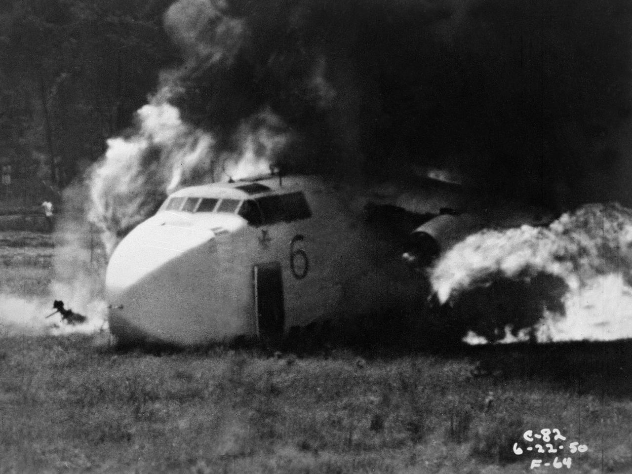
Researchers at the National Advisory Committee for Aeronautics (NACA) Lewis Flight Propulsion Laboratory purposely crash a Fairchild C-82 Packet aircraft to study flame propagation. A rash of passenger aircraft crashes in 1946 and 1947 spurred a White House call for an investigatory board staffed by members of the Civil Aeronautics Board, military, and the NACA. The group addressed fire segregation, extinguishment, and prevention. The NACA established a Subcommittee on Aircraft Fire Prevention in February 1948 to coordinate its efforts. The Lewis team simulated situations in which an aircraft failed to become airborne during takeoff resulting in crashes into embankments and other objects. The Lewis researchers initially used surplus C-46 and C-82 military transport planes. In these situations, the aircraft generally suffered damage to its fuel system and other components, but was structurally survivable. The aircraft were mounted to a rail that ran down a 1700-foot long test runway. The aircraft was secured at the starting point with an anchor pier so it could get its engines up to takeoff speed before launching down the track. Barriers at the end of the runway were designed to simulate a variety of different types of crashes. Telemetry and high-speed cameras were crucial elements in these studies. The preliminary testing phase identified potential ignition sources and analyzed the spread of flammable materials.
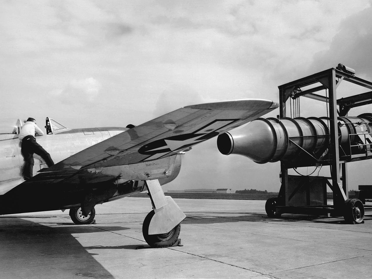
A Republic P-47G Thunderbolt is tested with a large blower on the hangar apron at the National Advisory Committee for Aeronautics (NACA) Aircraft Engine Research Laboratory in Cleveland, Ohio. The blower could produce air velocities up to 250 miles per hour. This was strong enough to simulate take-off power and eliminated the need to risk flights with untried engines. The Republic P-47G was loaned to the laboratory to test NACA modifications to the Wright R-2800 engine’s cooling system at higher altitudes. The ground-based tests, seen here, were used to map the engine’s normal operating parameters. The P-47G then underwent an extensive flight test program to study temperature distribution among the engine’s 18 cylinders and develop methods to improve that distribution.

Researchers at the National Advisory Committee for Aeronautics (NACA) Lewis Flight Propulsion Laboratory conducted an extensive investigation into the composition of clouds and their effect on aircraft icing. The researcher in this photograph is installing cameras on a Beach AT-11 Kansan in order to photograph water droplets during flights through clouds. The twin engine AT-11 was the primary training aircraft for World War II bomber crews. The NACA acquired this aircraft in January 1946, shortly after the end of the war. The NACA Lewis’ icing research during the war focused on the resolution of icing problems for specific military aircraft. In 1947 the laboratory broadened its program and began systematically measuring and categorizing clouds and water droplets. The three main thrusts of the Lewis icing flight research were the development of better instrumentation, the accumulation of data on ice buildup during flight, and the measurement of droplet sizes in clouds. The NACA researchers developed several types of measurement devices for the icing flights, including modified cameras. The National Research Council of Canada experimented with high-speed cameras with a large magnification lens to photograph the droplets suspended in the air. In 1951 NACA Lewis developed and flight tested their own camera with a magnification of 32. The camera, mounted to an external strut, could be used every five seconds as the aircraft reached speeds up to 150 miles per hour. The initial flight tests through cumulus clouds demonstrated that droplet size distribution could be studied.
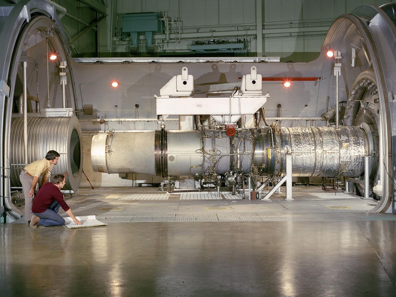
A refanned Pratt and Whitney JT-8D-109 turbofan engine installed in Cell 4 of the Propulsion Systems Laboratory at the National Aeronautics and Space Administration (NASA) Lewis Research Center. NASA Lewis’ Refan Program sought to demonstrate that noise reduction modifications could be applied to existing aircraft engines with minimal costs and without diminishing the engine’s performance or integrity. At the time, Pratt and Whitney’s JT-8D turbofans were one of the most widely used engines in the commercial airline industry. The engines powered Boeing’s 727 and 737 and McDonnell Douglas’ DC-9 aircraft. Pratt and Whitney worked with the airline manufacturers on a preliminary study that verified feasibility of replacing the JT-8D’s two-stage fan with a larger single-stage fan. The new fan slowed the engine’s exhaust, which significantly reduced the amount of noise it generated. Booster stages were added to maintain the proper level of airflow through the engine. Pratt and Whitney produced six of the modified engines, designated JT-8D-109, and performed the initial testing. One of the JT-8D-109 engines, seen here, was tested in simulated altitude conditions in NASA Lewis’ Propulsion Systems Laboratory. The Refan engine was ground-tested on an actual aircraft before making a series of flight tests on 727 and DC-9 aircraft in early 1976. The Refan Program reduced the JT-8D’s noise by 50 percent while increasing the fuel efficiency. The retro-fit kits were estimated to cost between $1 million and $1.7 million per aircraft.
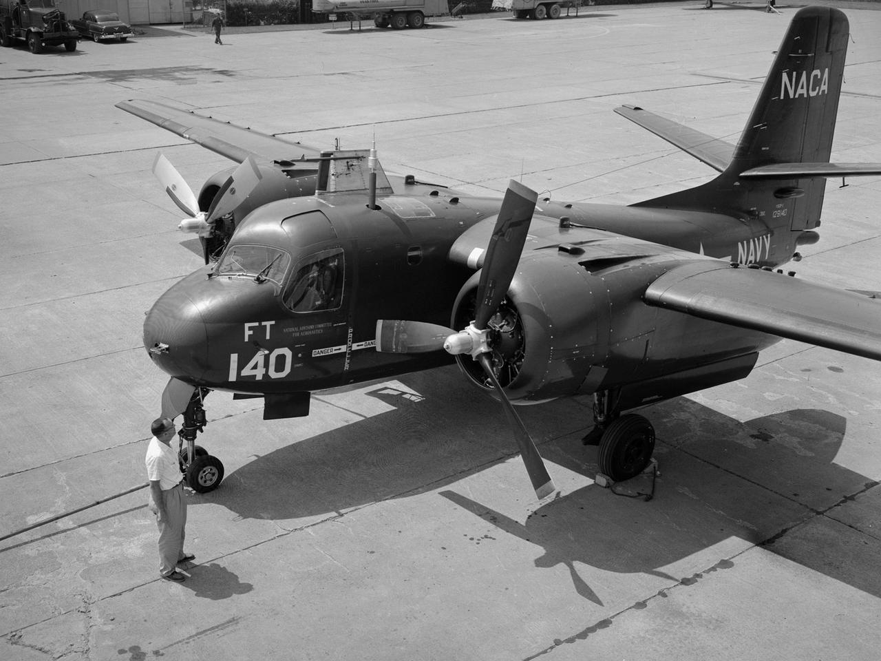
The NACA’s Lewis Flight Propulsion Laboratory acquired the Grumman S2F-1 Tracker from the Navy in 1955 to study icing instrumentation. Lewis’s icing research program was winding down at the time. The use of jet engines was increasing thus reducing the threat of ice accumulation. Nonetheless Lewis continued research on the instrumentation used to detect icing conditions. The S2F-1 Tracker was a carrier-based submarine hunter for the Navy. Grumman developed the Tracker as a successor to its Korean War-era Guardian patrol aircraft. Prototypes first flew in late 1952 and battle-ready versions entered Naval service in early 1954. The Navy utilized the Trackers to protect fleets from attack.
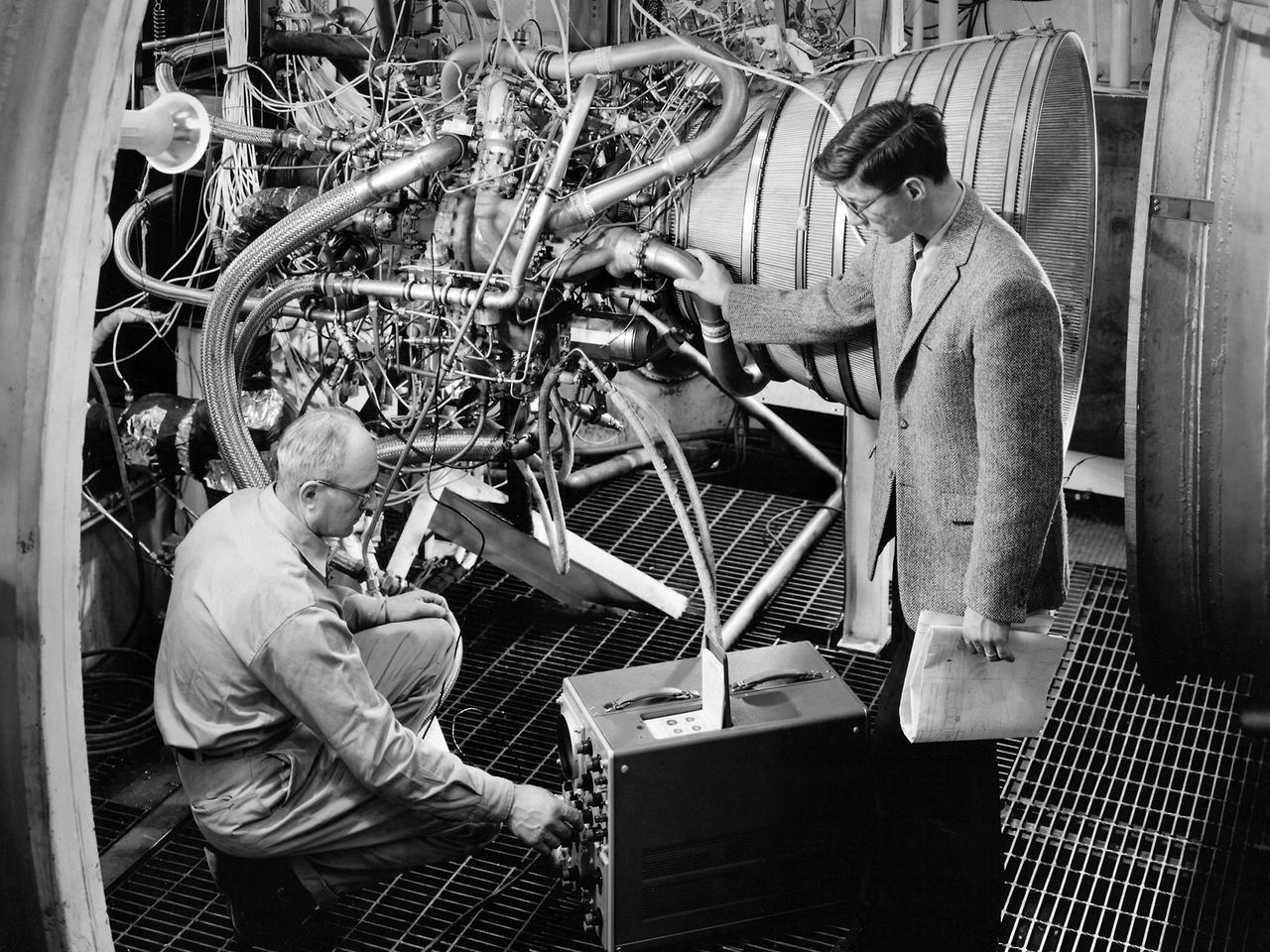
Lead Test Engineer John Kobak (right) and a technician use an oscilloscope to test the installation of a Pratt and Whitney RL-10 engine in the Propulsion Systems Laboratory at the National Aeronautics and Space Administration (NASA) Lewis Research Center. In 1955 the military asked Pratt and Whitney to develop hydrogen engines specifically for aircraft. The program was canceled in 1958, but Pratt and Whitney decided to use the experience to develop a liquid-hydrogen rocket engine, the RL-10. Two of the 15,000-pound-thrust RL-10 engines were used to power the new Centaur second-stage rocket. Centaur was designed to carry the Surveyor spacecraft on its mission to soft-land on the Moon. Pratt and Whitney ran into problems while testing the RL-10 at their facilities. NASA Headquarters assigned Lewis the responsibility for investigating the RL-10 problems because of the center’s long history of liquid-hydrogen development. Lewis’ Chemical Rocket Division began a series of tests to study the RL-10 at its Propulsion Systems Laboratory in March 1960. The facility contained two test chambers that could study powerful engines in simulated altitude conditions. The first series of RL-10 tests in early 1961 involved gimballing the engine as it fired. Lewis researchers were able to yaw and pitch the engine to simulate its behavior during a real flight.
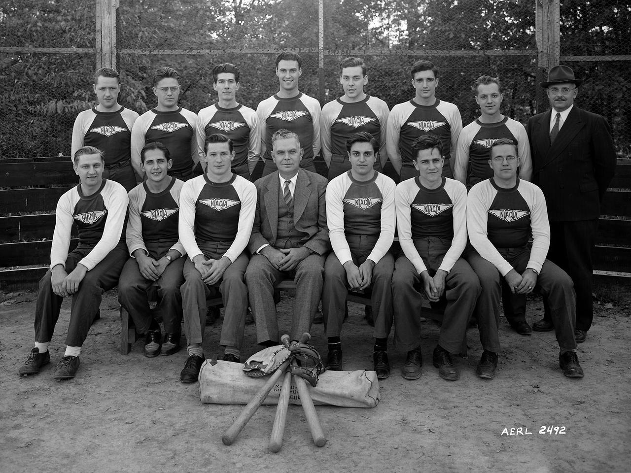
The NACA’s Aircraft Engine Research Laboratory’s baseball team photographed with director Raymond Sharp. The Exchange, which operated the non-profit cafeteria, sponsored several sports teams that participated in local leagues. The laboratory also had several intramural sports leagues. The baseball team, seen here in 1943, was suspended shortly thereafter as many of its members entered the military during World War II. The team was reconstituted after the war and became somewhat successful in the Class A Westlake League. After winning the championship in 1949 and 1950, the team was placed in the more advanced Middleberg League where they struggled.
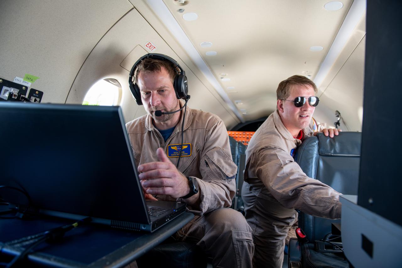
Adam Wroblewski and Shaun McKeehan Working In PC-12 Aircraft during in flight testing on June 13, 2024. A team at NASA’s Glenn Research Center in Cleveland streamed 4K video footage from an aircraft to the International Space Station and back for the first time using optical, or laser, communications. The feat was part of a series of tests on new technology that could provide live video coverage of astronauts on the Moon during the Artemis missions. Working with the Air Force Research Laboratory and NASA’s Small Business Innovation Research program, Glenn engineers temporarily installed a portable laser terminal on the belly of a Pilatus PC-12 aircraft. They then flew over Lake Erie sending data from the aircraft to an optical ground station in Cleveland. From there, it was sent over an Earth-based network to NASA’s White Sands Test Facility in Las Cruces, New Mexico, where scientists used infrared light signals to send the data. Photo Credit: (NASA/Sara Lowthian-Hanna)
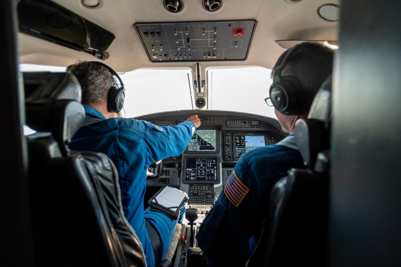
Kurt Blankenship and James Demers Fly PC-12 Aircraft During Testing on June 13, 2024. A team at NASA’s Glenn Research Center in Cleveland streamed 4K video footage from an aircraft to the International Space Station and back for the first time using optical, or laser, communications. The feat was part of a series of tests on new technology that could provide live video coverage of astronauts on the Moon during the Artemis missions. Working with the Air Force Research Laboratory and NASA’s Small Business Innovation Research program, Glenn engineers temporarily installed a portable laser terminal on the belly of a Pilatus PC-12 aircraft. They then flew over Lake Erie sending data from the aircraft to an optical ground station in Cleveland. From there, it was sent over an Earth-based network to NASA’s White Sands Test Facility in Las Cruces, New Mexico, where scientists used infrared light signals to send the data. Photo Credit: (NASA/Sara Lowthian-Hanna)
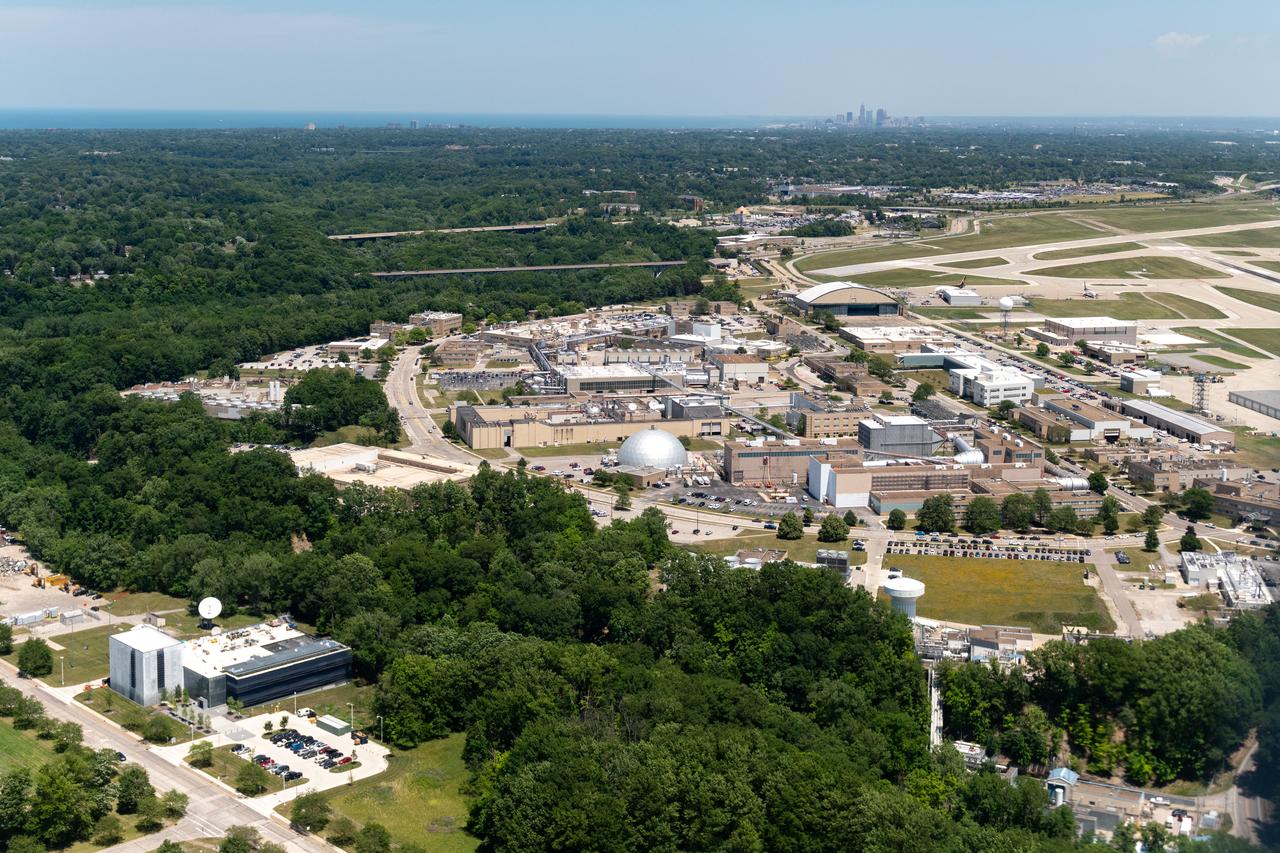
Aerial Photograph of Glenn Research Center With Downtown Cleveland in the Distance taken from the PC-12 on June 13, 2024. A team at NASA’s Glenn Research Center in Cleveland streamed 4K video footage from an aircraft to the International Space Station and back for the first time using optical, or laser, communications. The feat was part of a series of tests on new technology that could provide live video coverage of astronauts on the Moon during the Artemis missions. Working with the Air Force Research Laboratory and NASA’s Small Business Innovation Research program, Glenn engineers temporarily installed a portable laser terminal on the belly of a Pilatus PC-12 aircraft. They then flew over Lake Erie sending data from the aircraft to an optical ground station in Cleveland. From there, it was sent over an Earth-based network to NASA’s White Sands Test Facility in Las Cruces, New Mexico, where scientists used infrared light signals to send the data. Photo Credit: (NASA/Sara Lowthian-Hanna)
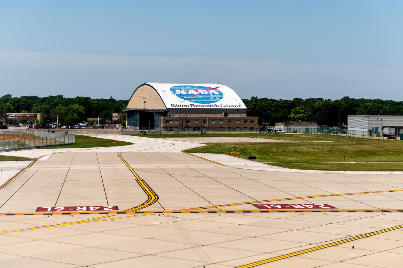
View of the Glenn Research Center Hangar from the Cleveland Hopkins Airport Runway during a testing flight on June 13, 2024. A team at NASA’s Glenn Research Center in Cleveland streamed 4K video footage from an aircraft to the International Space Station and back for the first time using optical, or laser, communications. The feat was part of a series of tests on new technology that could provide live video coverage of astronauts on the Moon during the Artemis missions. Working with the Air Force Research Laboratory and NASA’s Small Business Innovation Research program, Glenn engineers temporarily installed a portable laser terminal on the belly of a Pilatus PC-12 aircraft. They then flew over Lake Erie sending data from the aircraft to an optical ground station in Cleveland. From there, it was sent over an Earth-based network to NASA’s White Sands Test Facility in Las Cruces, New Mexico, where scientists used infrared light signals to send the data. Photo Credit: (NASA/Sara Lowthian-Hanna)
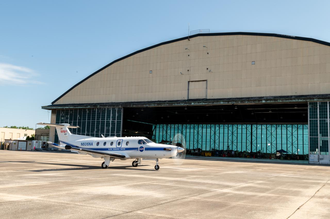
At Glenn Research Center, the PC-12 is Prepped for a flight and ready to takeoff on June 12, 2024. A team at NASA’s Glenn Research Center in Cleveland streamed 4K video footage from an aircraft to the International Space Station and back for the first time using optical, or laser, communications. The feat was part of a series of tests on new technology that could provide live video coverage of astronauts on the Moon during the Artemis missions. Working with the Air Force Research Laboratory and NASA’s Small Business Innovation Research program, Glenn engineers temporarily installed a portable laser terminal on the belly of a Pilatus PC-12 aircraft. They then flew over Lake Erie sending data from the aircraft to an optical ground station in Cleveland. From there, it was sent over an Earth-based network to NASA’s White Sands Test Facility in Las Cruces, New Mexico, where scientists used infrared light signals to send the data. Photo Credit: (NASA/Sara Lowthian-Hanna)
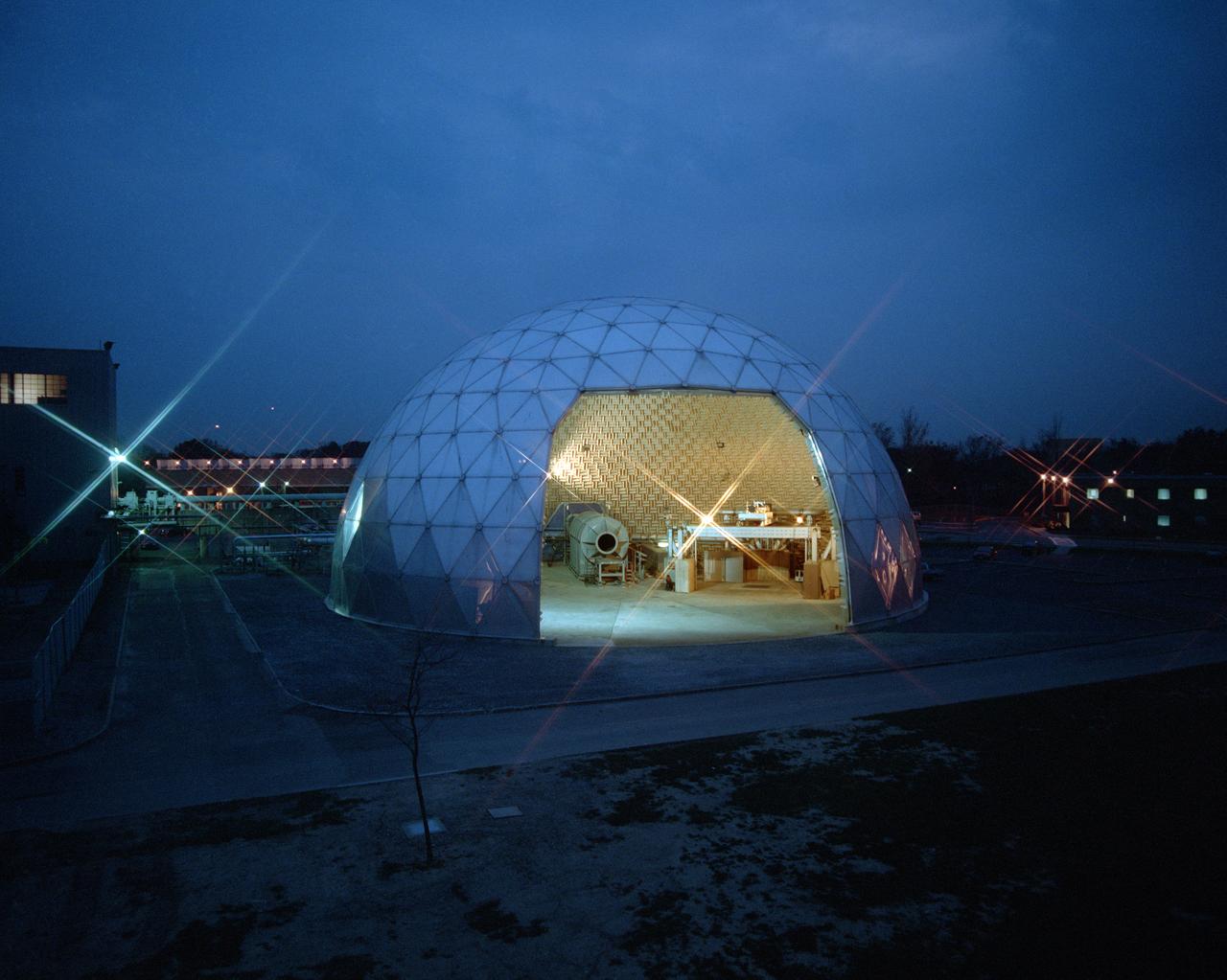
Modern jet engines are loud, but they used to be much louder. NASA’s Glenn Research Center has been at the forefront of the nation’s efforts to reduce aircraft engine noise for over 70 years. During this time, the center has built an array of test facilities to carry out this work, culminating in the Aero-Acoustic Propulsion Laboratory (AAPL), a world-class noise-reduction research facility. The AAPL, referred to as “the dome,” contains multiple test rigs enclosed in a large, echo-free chamber. The unique 130-foot diameter and 65-foot-high hemispherical structure stands out on Glenn’s campus. Its triangular sections make it appear like a golf ball rising from the ground. The interior is covered in spiky, fiberglass sound-dampening wedges and an overhead array of microphones that capture engine noise data.
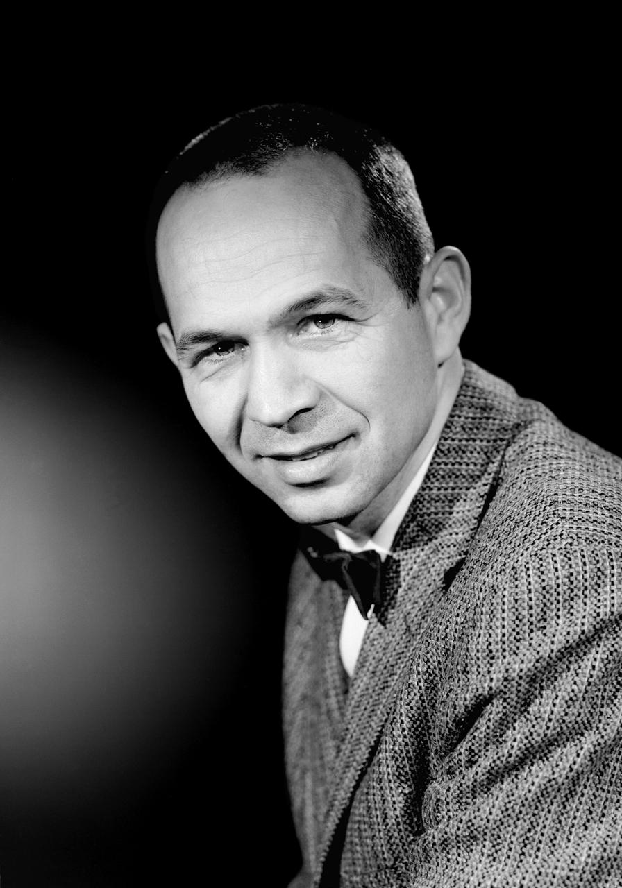
L59-1497-6 Maxime A. Faget was born in British Honduras in 1921, the son of an honored physician of the U.S. Public Health Service. In 1943 he earned a B.S. in mechanical engineering from Louisiana State University. After service as a navy submarine officer, he joined the Langley staff in 1946 as a member of the Pilotless Aircraft Research Division. His early work for PARD involved the invention of choking inlets for ramjets and a flight Mach meter. Photograph published in Engineer in Charge: A History of the Langley Aeronautical Laboratory, 1917-1958 by James R. Hansen. Page 379.
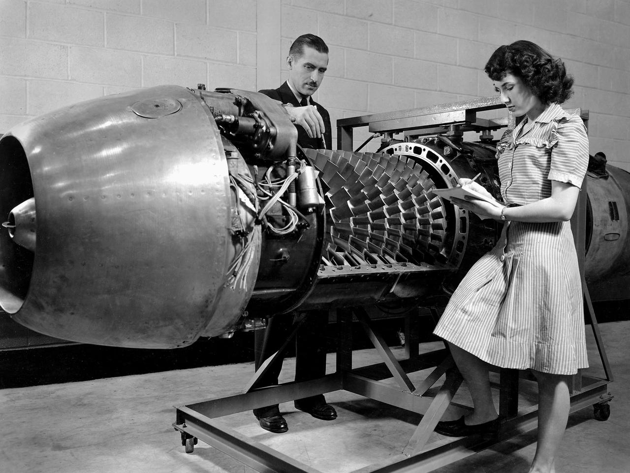
Researcher Robert Miller led an investigation into the combustor performance of a German Jumo 004 engine at the National Advisory Committee for Aeronautics (NACA) Lewis Flight Propulsion Laboratory. The Jumo 004 powered the world's first operational jet fighter, the Messerschmitt Me 262, beginning in 1942. The Me 262 was the only jet aircraft used in combat during World War II. The eight-stage axial-flow compressor Jumo 004 produced 2000 pounds of thrust. The US Army Air Forces provided the NACA with a Jumo 004 engine in 1945 to study the compressor’s design and performance. Conveniently the engine’s designer Anselm Franz had recently arrived at Wright-Patterson Air Force Base in nearby Dayton, Ohio as part of Project Paperclip. The Lewis researchers used a test rig in the Engine Research Building to analyze one of the six combustion chambers. It was difficult to isolate a single combustor’s performance when testing an entire engine. The combustion efficiency, outlet-temperature distribution, and total pressure drop were measured. The researchers determined the Jumo 004’s maximum performance was 5000 revolutions per minute at a 27,000 foot altitude and 11,000 revolutions per minute at a 45,000 foot altitude. The setup in this photograph was created for a tour of NACA Lewis by members of the Institute of Aeronautical Science on March 22, 1945.
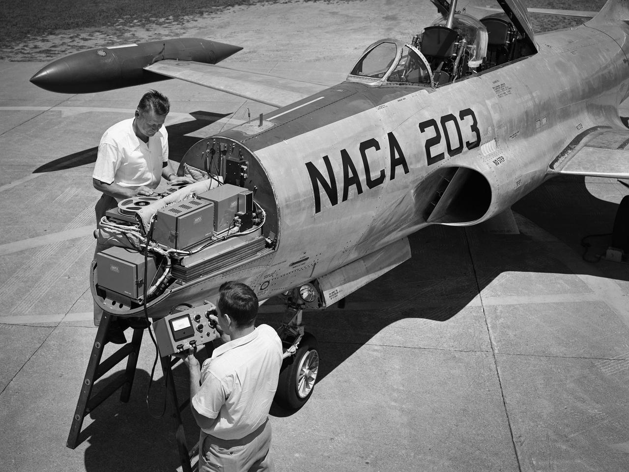
A Lockheed F-94B Starfire being equipped with an audio recording machine and sensors at the National Advisory Committee for Aeronautics (NACA) Lewis Flight Propulsion Laboratory. The NACA was investigating the acoustic effects caused by the engine’s nozzle and the air flowing along the fuselage. Airline manufacturers would soon be introducing jet engines on their passenger aircraft, and there was concern regarding the noise levels for both the passengers and public on the ground. NACA Lewis conducted a variety of noise reduction studies in its wind tunnels, laboratories, and on a F2H-2B Banshee aircraft. The F2H-2B Banshee’s initial test flights in 1955 and 1956 measured the noise emanating directly from airflow over the aircraft’s surfaces, particularly the wings. This problem was particularly pronounced at high subsonic speeds. The researchers found the majority of the noise occurred in the low and middle octaves. These investigations were enhanced with a series of flights using the F-94B Starfire. The missions measured wall-pressure, turbulence fluctuations, and mean velocity profiles. Mach 0.3 to 0.8 flights were flown at altitudes of 10,000, 20,000, and 30,000 feet with microphones mounted near the forward fuselage and on a wing. The results substantiated the wind tunnel findings. This photograph shows the tape recorder being installed in the F-94B’s nose.
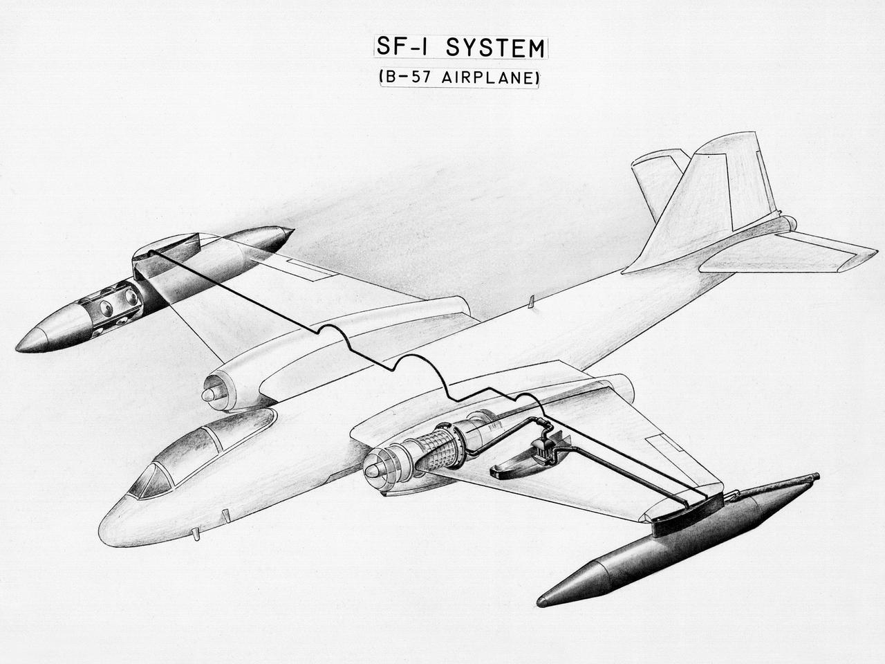
This diagram shows a hydrogen fuel system designed by researchers at the National Advisory Committee for Aeronautics (NACA) Lewis Flight Propulsion Laboratory and installed on a Martin B-57B Canberra aircraft. Lewis researchers accelerated their studies of high energy propellants in the early 1950s. In late 1954, Lewis researchers studied the combustion characteristics of gaseous hydrogen in a turbojet combustor. It was found that the hydrogen provided a very high efficiency. Almost immediately thereafter, Associate Director Abe Silverstein became focused on the possibilities of hydrogen for aircraft propulsion. That fall, Silverstein secured a contract to work with the air force to examine the practicality of liquid hydrogen aircraft. A B-57B Canberra was obtained by the air force especially for this project, referred to as Project Bee. The aircraft was powered by two Wright J65 engines, one of which was modified so that it could be operated using either traditional or liquid hydrogen propellants. The engine and its liquid hydrogen fuel system were tested extensively in the Altitude Wind Tunnel and the Four Burner Area test cells in 1955 and 1956. A B-57B flight program was planned to test the system on an actual aircraft. The aircraft would take off using jet fuel, switch to liquid hydrogen while over Lake Erie, then after burning the hydrogen supply switch back to jet fuel for the landing. The third test flight, in February 1957, was a success, and the ensuing B-57B flights remain the only demonstration of hydrogen-powered aircraft.
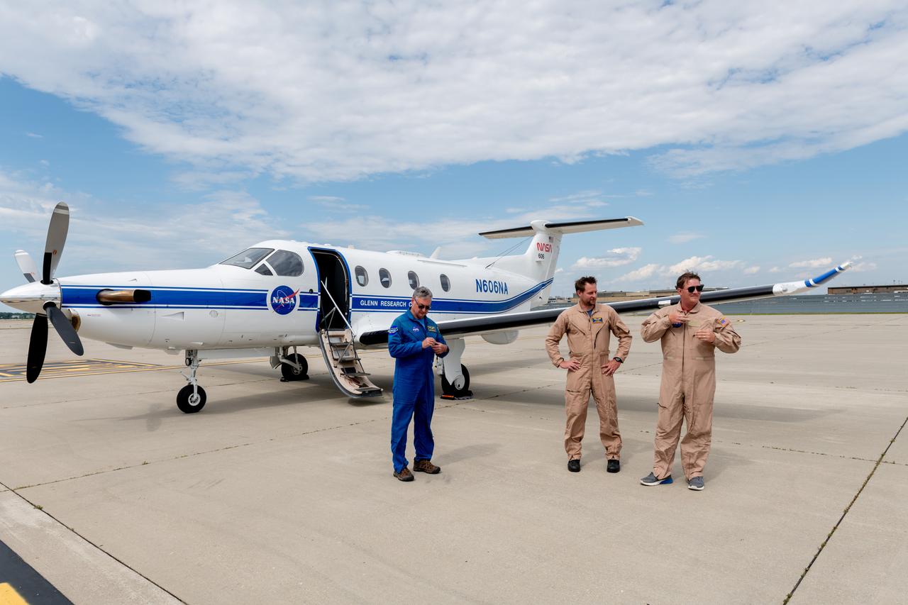
A team at NASA’s Glenn Research Center in Cleveland streamed 4K video footage from an aircraft to the International Space Station and back for the first time using optical, or laser, communications. The feat was part of a series of tests on new technology that could provide live video coverage of astronauts on the Moon during the Artemis missions. Pictured here on June 13, 2024 from Left to Right: Kurt Blakenship, Adam Wroblewski, Shaun McKeehan. Working with the Air Force Research Laboratory and NASA’s Small Business Innovation Research program, Glenn engineers temporarily installed a portable laser terminal on the belly of a Pilatus PC-12 aircraft. They then flew over Lake Erie sending data from the aircraft to an optical ground station in Cleveland. From there, it was sent over an Earth-based network to NASA’s White Sands Test Facility in Las Cruces, New Mexico, where scientists used infrared light signals to send the data. Photo Credit: (NASA/Sara Lowthian-Hanna)

A Republic F-84 Thunderjet dramatically modified at the NASA Lewis Research Center to investigate the use of slotted nozzles to reduce exhaust noise. The F-84 was a single-seat fighter-bomber powered by an Allison J35 turbojet. It was the Air Force’s first post-World War II tactical aircraft and was used extensively in the Korean War. The laboratory had acquired the aircraft in 1954 and modified it in order to demonstrate the reverse thruster. The tail end of the aircraft was then removed for a series of large nozzle investigations. Lewis researchers launched an extensive program in the mid-1950s to develop methods of reducing engine noise as the airline industry was preparing to introduce the first turbojet-powered passenger aircraft. The early NACA investigations determined that the primary source of noise was the mixing of the engine’s hot exhaust with the cool surrounding air. Lewis researchers studied many different nozzles designed to facilitate this mixing. Nozzles with elongated exit sections, as seen in this photograph, produced lower noise levels. These long slot nozzles were also considered for Short Take-off and Landing aircraft because their long flat surfaces provided lift. In 1958 Lewis tested several full-scale slot nozzles on the F-84. The researchers, led by Willard Cole, sought to determine the noise-generation characteristics for nozzles having large a width-to-height ratio. The nozzle in this photograph has a 100 to 1 width-to-height ratio. Cole determined that the experimental nozzles produced the same levels of sound as the standard nozzle, but the changes in the directional noise were substantial.
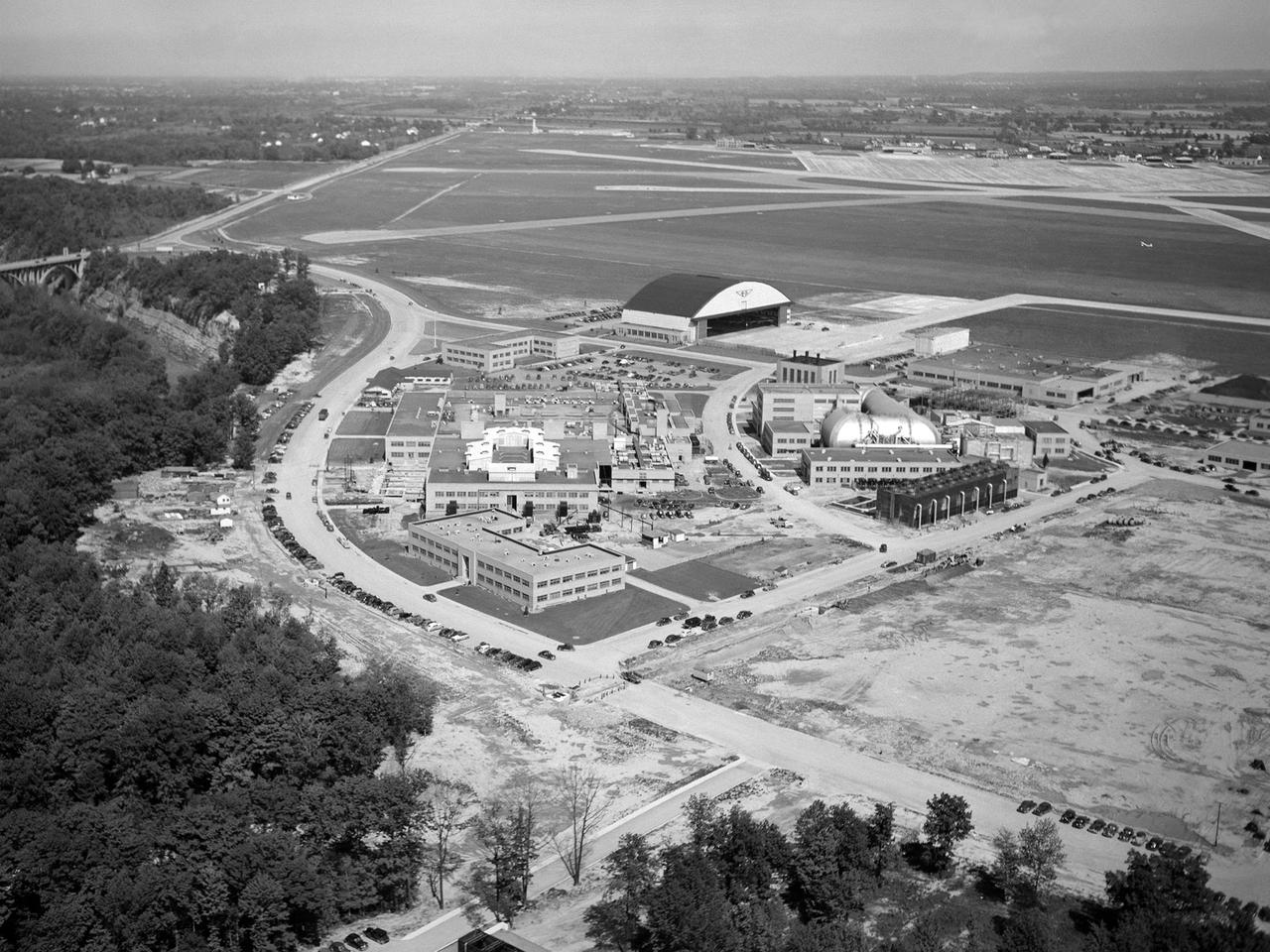
The National Advisory Committee for Aeronautics (NACA) Lewis Flight Propulsion Laboratory in Cleveland, Ohio as seen from the west in May 1946. The Cleveland Municipal Airport is located directly behind. The laboratory was built in the early 1940s to resolve problems associated with aircraft engines. The initial campus contained seven principal buildings: the Engine Research Building, hangar, Fuels and Lubricants Building, Administration Building, Engine Propeller Research Building, Altitude Wind Tunnel, and Icing Research Tunnel. These facilities and their associated support structures were located within an area occupying approximately one-third of the NACA’s property. After World War II ended, the NACA began adding new facilities to address different problems associated with the newer, more powerful engines and high speed flight. Between 1946 and 1955, four new world-class test facilities were built: the 8- by 6-Foot Supersonic Wind Tunnel, the Propulsion Systems Laboratory, the Rocket Engine Test Facility, and the 10- by 10-Foot Supersonic Wind Tunnel. These large facilities occupied the remainder of the NACA’s semicircular property. The Lewis laboratory expanded again in the late 1950s and early 1960s as the space program commenced. Lewis purchased additional land in areas adjacent to the original laboratory and acquired a large 9000-acre site located 60 miles to the west in Sandusky, Ohio. The new site became known as Plum Brook Station.
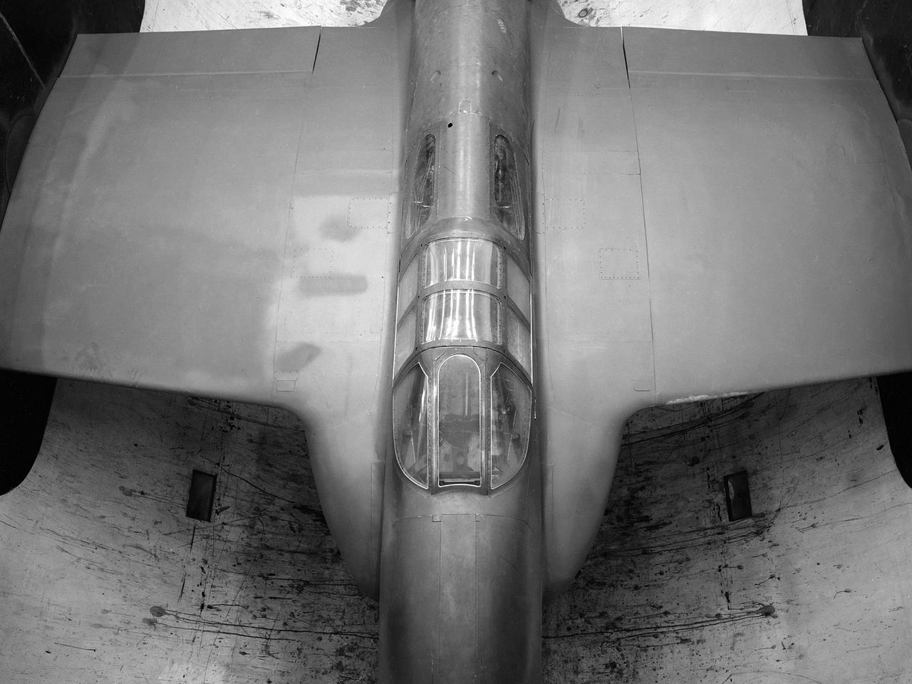
The secret test of the Bell YP–59A Airacomet in the spring of 1944 was the first investigation in the National Advisory Committee for Aeronautics (NACA) Aircraft Engine Research Laboratory’s new Altitude Wind Tunnel (AWT). The Airacomet, powered by two General Electric I–A centrifugal turbojets, was the first US jet aircraft. The Airacomet’s 290-miles per hour speed, however, was dwarfed by the German Messerschmitt Me-262 Schwalbe’s 540 miles per hour. In 1941 and 1942 General Electric built the first US jet engines based on technical drawings from British engineer Frank Whittle. Bell Aircraft was contracted to produce an airframe to incorporate the new engines. The result was the Bell XP–59A Airacomet. The aircraft made its first flight over Muroc Lake, California, on October 2, 1942. The aircraft continued to struggle over the next year and the NACA was asked to test it in the new AWT. A Bell YP–59A was flown from the Bell plant in Buffalo to Cleveland by Bob Stanley, who had piloted the first successful flight of the XP–59A at Muroc in 1942. The wing tips and tail were cut from the aircraft so that it would fit into the AWT’s test section. The study first analyzed the engines in their original configuration and then implemented a boundary layer removal duct, a new nacelle inlet, and new cooling seals. Tests of the modified version showed that the improved airflow distribution increased the I–16’s performance by 25 percent. Despite the improved speed, the aircraft was not stable enough to be used in combat, and the design was soon abandoned.