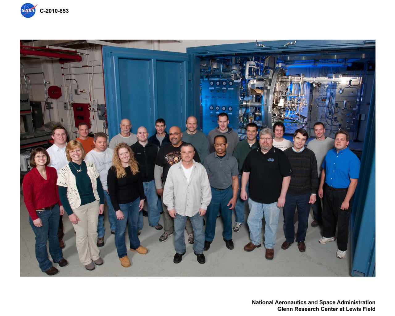
Altitude Combustion Stand Team Personnel
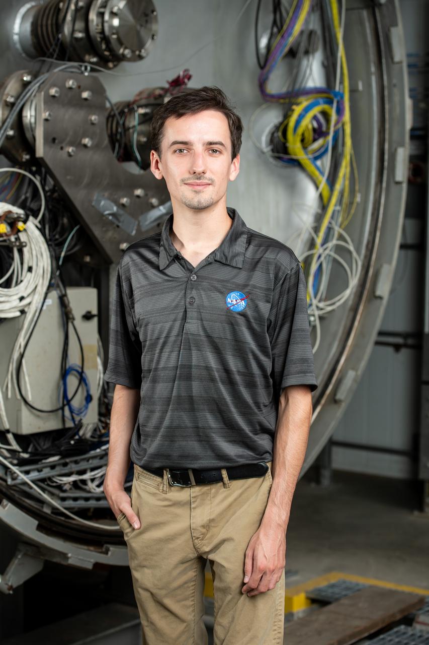
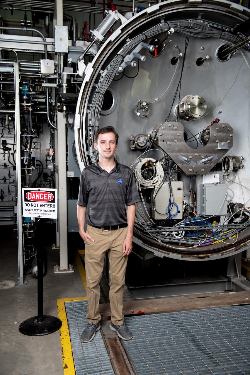
Each year, the NESC produces the NESC Technical Update, which highlights two or three individuals from each Center and includes assessments throughout the year. Because of the critical contributions to the NESC mission this year, Rob Jankovsky, NESC Chief Engineer at GRC, chose two individuals to be highlighted. This year, it is Andrew Ring and Michael Cooper. The Lead Analyst for GRC’s Chemical and Thermal Propulsion Systems branch, Mr. Michael Cooper, is supporting NESC test operations on reaction control system thrusters for Gateway’s Power & Propulsion Element. “These thrusters are small with few moving parts, but the heat and mass transfers involved are very complex,” he said. The test campaign is putting the thrusters through a rigorous profile to simulate the lifetime they will experience over decades in space. Mr. Cooper is analyzing test data gathered on chamber pressure, temperature, flow rates, and more to develop models on thruster performance. He also built the tool that read in that data from the test stand instrumentation. Photo Credit: (NASA/Sara Lowthian-Hanna)
Each year, the NESC produces the NESC Technical Update, which highlights two or three individuals from each Center and includes assessments throughout the year. Because of the critical contributions to the NESC mission this year, Rob Jankovsky, NESC Chief Engineer at GRC, chose two individuals to be highlighted. This year, it is Andrew Ring and Michael Cooper. The Lead Analyst for GRC’s Chemical and Thermal Propulsion Systems branch, Mr. Michael Cooper, is supporting NESC test operations on reaction control system thrusters for Gateway’s Power & Propulsion Element. “These thrusters are small with few moving parts, but the heat and mass transfers involved are very complex,” he said. The test campaign is putting the thrusters through a rigorous profile to simulate the lifetime they will experience over decades in space. Mr. Cooper is analyzing test data gathered on chamber pressure, temperature, flow rates, and more to develop models on thruster performance. He also built the tool that read in that data from the test stand instrumentation. Photo Credit: (NASA/Sara Lowthian-Hanna)
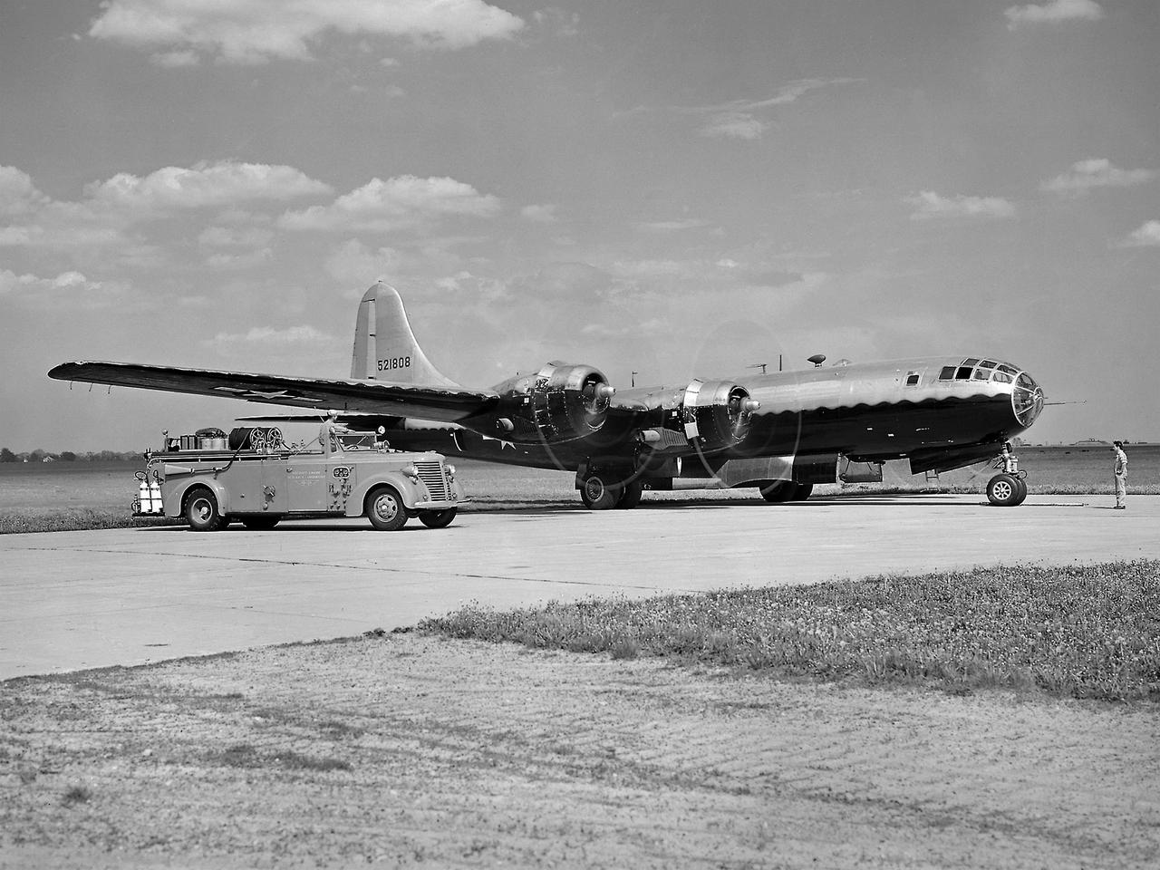
The NACA’s Lewis Flight Propulsion Laboratory used a Boeing B-29 Superfortress as a testbed for ramjet investigations in the late 1940s. NACA Lewis conducted a wide variety of studies on ramjets to determine basic operational data necessary to design missiles. This information included the relationship between combustion chamber and inlet pressure and temperature, velocity of the fuel-air ratio to the ignition characteristics, and combustion efficiency. Although wind tunnel and test stand studies were important first steps in determining these factors, actual flight tests were required. Lewis engineers modified the B-29 so that the ramjet could be stored in the bomb bay. Once the aircraft reached the desired altitude and speed the ramjet was suspended 52 inches below the bomb bay. The ramjet’s angle-of-attack could be independently adjusted, and a periscope permitted a view of the test article from inside the aircraft. Measurements were taken in free-stream conditions between 5,000 and 30,000 feet. The test flights, which began in April 1947, were flown at speeds up to Mach 0.51 and altitudes of 5,000 to 30,000 feet. The researchers first determined that 14,000 feet was the maximum altitude at which the engine could be ignited by spark. Flares were used to start the engine at altitudes up to 30,000 feet. Overall the ramjet operated well at all speeds and altitudes. Significant changes in fuel flow were successful at lower altitudes, but produced combustion blowout above 20,000 feet.
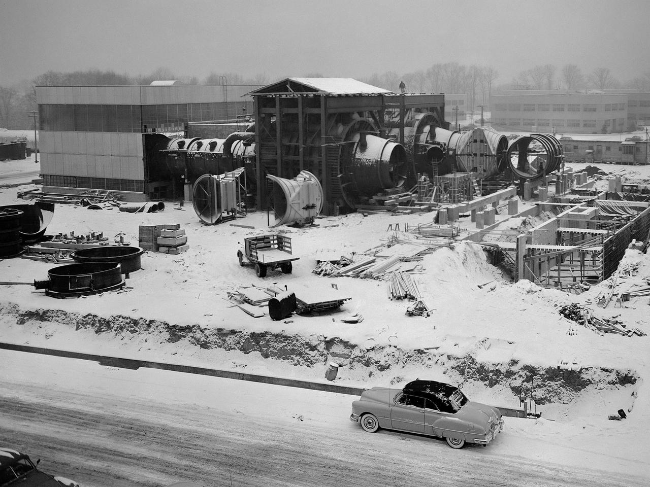
Construction of the Propulsion Systems Laboratory No. 1 and 2 at the National Advisory Committee for Aeronautics (NACA) Lewis Flight Propulsion Laboratory. When it began operation in late 1952, the Propulsion Systems Laboratory was the NACA’s most powerful facility for testing full-scale engines at simulated flight altitudes. The facility contained two altitude simulating test chambers which were a technological combination of the static sea-level test stands and the complex Altitude Wind Tunnel, which recreated actual flight conditions on a larger scale. NACA Lewis began designing the new facility in 1947 as part of a comprehensive plan to improve the altitude testing capabilities across the lab. The exhaust, refrigeration, and combustion air systems from all the major test facilities were linked. In this way, different facilities could be used to complement the capabilities of one another. Propulsion Systems Laboratory construction began in late summer 1949 with the installation of an overhead exhaust pipe connecting the facility to the Altitude Wind Tunnel and Engine Research Building. The large test section pieces arriving in early 1951, when this photograph was taken. The two primary coolers for the altitude exhaust are in place within the framework near the center of the photograph.
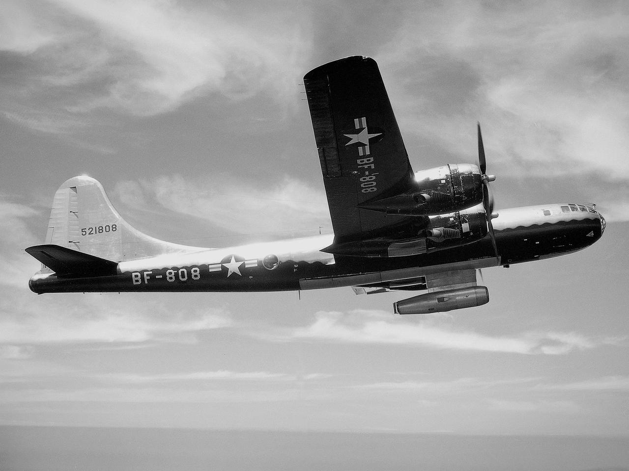
The NACA’s Lewis Flight Propulsion Laboratory used a Boeing B‒29 Superfortress as a testbed for ramjet investigations in the late 1940s. Lewis researchers conducted a wide variety of studies on ramjets to determine basic the operational data necessary to design missiles. Extensive wind tunnel and test stand studies were augmented by actual flight tests. Lewis engineers modified this B‒29 so that the ramjet could be stored in the bomb bay. Once the aircraft reached the desired altitude and speed, a mechanical arm suspended the ramjet 52 inches below the bomb bay. The ramjet’s angle-of-attack could be independently adjusted, and a periscope permitted a view of the test article from inside the aircraft. Researchers took measurements in free-stream conditions at speeds up to Mach 0.51 and at altitudes ranging from 5,000 to 30,000 feet. They then shut the ramjet down and retracted it into the aircraft. The researchers first determined that 14,000 feet was the maximum altitude at which the engine could be ignited by spark. They used flares to start the engine at altitudes up to 30,000 feet. They were able to determine maximum combustion efficiencies, response time to changes in fuel flow, and minimum fuel-air ratios. Overall the ramjet operated well at all speeds and altitudes.
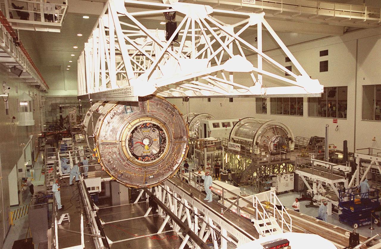
KENNEDY SPACE CENTER, FLA. -- The U.S. Laboratory Destiny, a component of the International Space Station, is lifted off a weigh stand (below) in the Space Station Processing Facility. The module is being moved to a payload canister for transfer to the Operations and Checkout Building where it will be tested in the altitude chamber. Destiny is scheduled to fly on mission STS-98 in early 2001. During the mission, the crew will install the Lab in the Space Station during a series of three space walks. The STS-98 mission will provide the Station with science research facilities and expand its power, life support and control capabilities. The U.S. Lab module continues a long tradition of microgravity materials research, first conducted by Skylab and later Shuttle and Spacelab missions. Destiny is expected to be a major feature in future research, providing facilities for biotechnology, fluid physics, combustion, and life sciences research

KENNEDY SPACE CENTER, FLA. -- The U.S. Laboratory Destiny, a component of the International Space Station, is lifted off a weigh stand (below) in the Space Station Processing Facility. The module is being moved to a payload canister for transfer to the Operations and Checkout Building where it will be tested in the altitude chamber. Destiny is scheduled to fly on mission STS-98 in early 2001. During the mission, the crew will install the Lab in the Space Station during a series of three space walks. The STS-98 mission will provide the Station with science research facilities and expand its power, life support and control capabilities. The U.S. Lab module continues a long tradition of microgravity materials research, first conducted by Skylab and later Shuttle and Spacelab missions. Destiny is expected to be a major feature in future research, providing facilities for biotechnology, fluid physics, combustion, and life sciences research
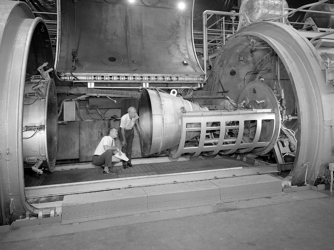
Bill Harrison and Bud Meilander check the setup of an Apollo Contour rocket nozzle in the Propulsion Systems Laboratory at the National Aeronautics and Space Administration (NASA) Lewis Research Center. The Propulsion Systems Laboratory contained two 14-foot diameter test chambers that could simulate conditions found at very high altitudes. The facility was used in the 1960s to study complex rocket engines such as the Pratt and Whitney RL-10 and rocket components such as the Apollo Contour nozzle, seen here. Meilander oversaw the facility’s mechanics and the installation of test articles into the chambers. Harrison was head of the Supersonic Tunnels Branch in the Test Installations Division. Researchers sought to determine the impulse value of the storable propellant mix, classify and improve the internal engine performance, and compare the results with analytical tools. A special setup was installed in the chamber that included a device to measure the thrust load and a calibration stand. Both cylindrical and conical combustion chambers were examined with the conical large area ratio nozzles. In addition, two contour nozzles were tested, one based on the Apollo Service Propulsion System and the other on the Air Force’s Titan transtage engine. Three types of injectors were investigated, including a Lewis-designed model that produced 98-percent efficiency. It was determined that combustion instability did not affect the nozzle performance. Although much valuable information was obtained during the tests, attempts to improve the engine performance were not successful.
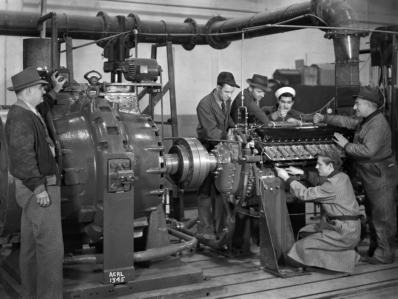
The first research assignment specifically created for the National Advisory Committee for Aeronautics’ (NACA) new Aircraft Engine Research Laboratory was the integration of a supercharger into the Allison V–1710 engine. The military was relying on the liquid-cooled V–1710 to power several types of World War II fighter aircraft and wanted to improve the engine's speed and altitude performance. Superchargers forced additional airflow into the combustion chamber, which increased the engine’s performance resulting in greater altitudes and speeds. They also generated excess heat that affected the engine cylinders, oil, and fuel. In 1943 the military tasked the new Aircraft Engine Research Laboratory to integrate the supercharger, improve the cooling system, and remedy associated engine knock. Three Allison engines were provided to the laboratory’s research divisions. One group was tasked with improving the supercharger performance, another analyzed the effect of the increased heat on knock in the fuel, one was responsible for improving the cooling system, and another would install the new components on the engine with minimal drag penalties. The modified engines were installed on this 2000-horsepower dynamotor stand in a test cell within the Engine Research Building. The researchers could run the engine at different temperatures, fuel-air ratios, and speeds. When the modifications were complete, the improved V–1710 was flight tested on a P–63A Kingcobra loaned to the NACA for this project.
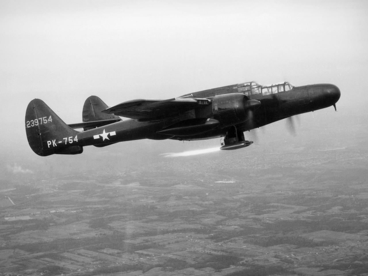
The National Advisory Committee for Aeronautics (NACA) Lewis Flight Propulsion Laboratory obtained a Northrop P-61 Black Widow in October 1945 and modified it to serve as a subsonic testbed for ramjet engines and swept-wing aircraft models. The P-61 was developed during World War II specifically for nighttime attacks. It was the largest and heaviest US fighter in the war. The P-61’s unique design included an abbreviated fuselage and twin booms that were joined by a single tail. To facilitate its nighttime missions, the P-61 was painted black and carried a radar system in its nose. It was designed so the crew could perform their flight and tracking tasks in complete darkness. NACA Lewis was in the midst of a massive research effort on ramjets when it acquired the Black Widow. Researchers used the aircraft to accelerate the ramjet until it reached a velocity at which it could be ignited. A ramjet can be seen being fired underneath the aircraft in this photograph. Sensors and instrumentation fed data from the ramjet to the pilot and researchers on the ground. The NACA researchers created a rectangular ramjet with a V-shaped gutter flameholder. The researchers installed the ramjet on the P-61 and flew it at subsonic speeds over a range of altitudes up to 29,000 feet. The ramjet had been previously tested at low speeds on a test stand on the hangar apron. The rectangular ramjet was also used to study different types of flameholders and nozzles used to spray fuel into the combustion chamber. The Black Widow was transferred from Lewis in October 1948.