JERRIE COBB - PILOT - TESTING GIMBAL RIG IN THE ALTITUDE WIND TUNNEL, AWT
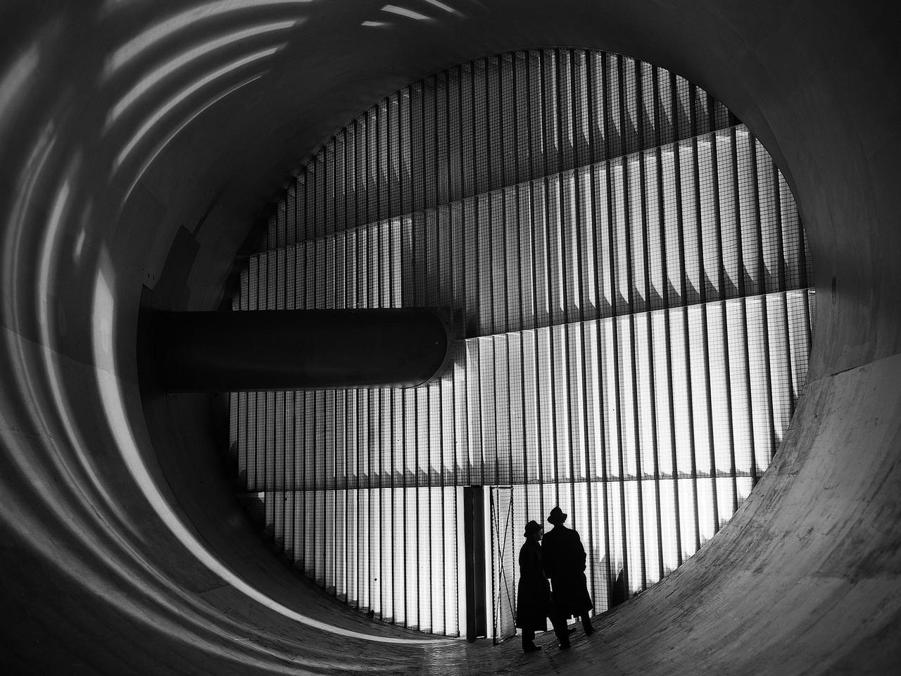
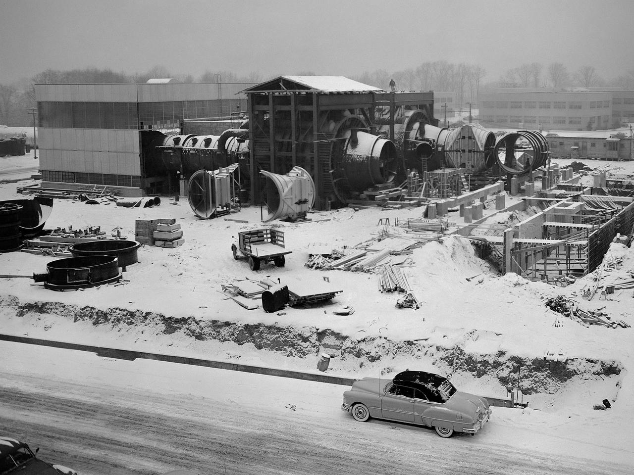
Altitude Wind Tunnel (AWT) construction: cutting tunnel
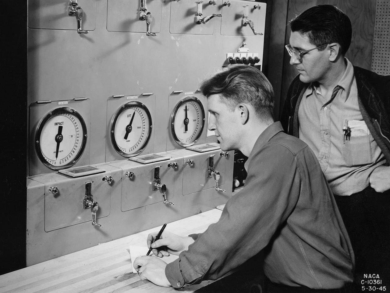
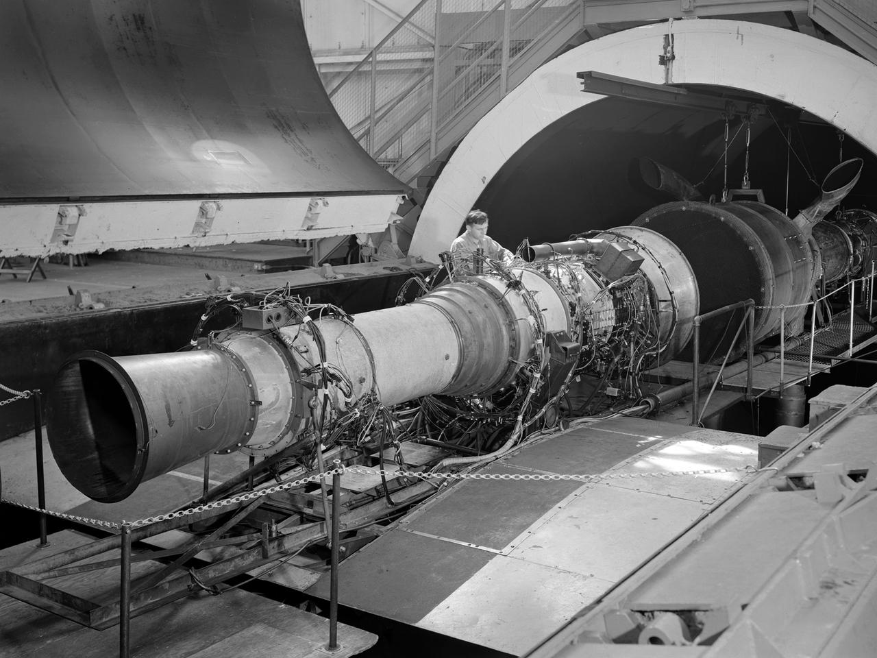
Researchers at the National Advisory Committee for Aeronautics (NACA) Aircraft Engine Research Laboratory monitor a ramjet's performance in the Altitude Wind Tunnel from the control room. The soundproof control room was just a few feet from the tunnel’s 20-foot-diameter test section. In the control room, the operators could control all aspects of the tunnel’s operation, including the air density, temperature, and speed. They also operated the engine or test article in the test section by controlling the angle-of-attack, speed, power, and other parameters. The men in this photograph are monitoring the engine’s thrust and lift. A NACA-designed 20-inch-diameter ramjet was installed in the tunnel in May 1945. Thrust figures from these runs were compared with drag data from tests of scale models in small supersonic tunnels to verify the ramjet’s feasibility. The tunnel was used to analyze the ramjet’s overall performance up to altitudes of 47,000 feet and speeds to Mach 1.84. The researchers found that an increase in altitude caused a reduction in the engine’s horsepower and identified optimal flameholder configurations.
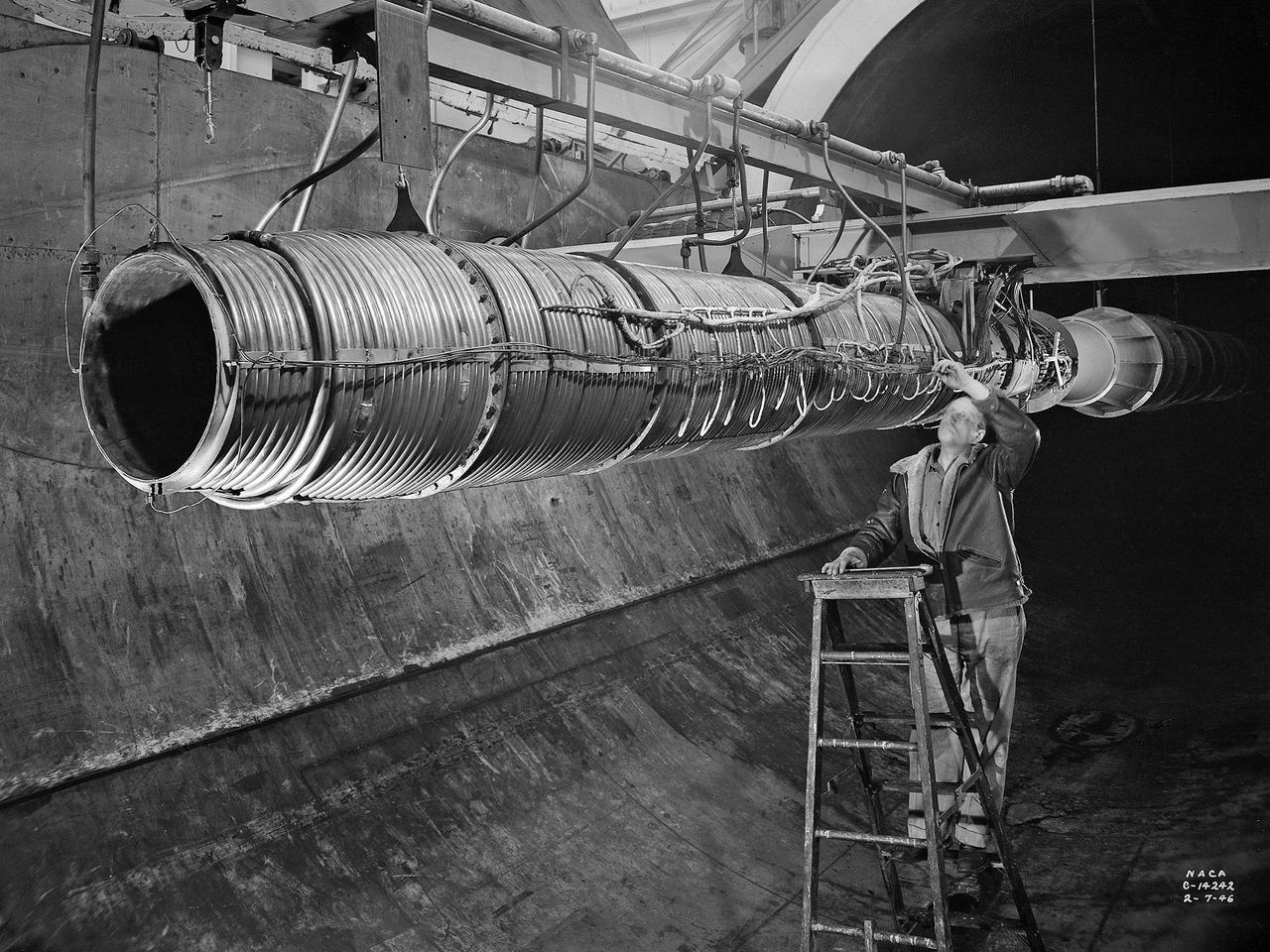
A 20-inch diameter ramjet installed in the Altitude Wind Tunnel at the National Advisory Committee for Aeronautics (NACA) Lewis Flight Propulsion Laboratory. The Altitude Wind Tunnel was used in the 1940s to study early ramjet configurations. Ramjets provide a very simple source of propulsion. They are basically a tube which takes in high-velocity air, ignites it, and then expels the expanded airflow at a significantly higher velocity for thrust. Ramjets are extremely efficient and powerful but can only operate at high speeds. Therefore a turbojet or rocket was needed to launch the vehicle. This NACA-designed 20-inch diameter ramjet was installed in the Altitude Wind Tunnel in May 1945. The ramjet was mounted under a section of wing in the 20-foot diameter test section with conditioned airflow ducted directly to the engine. The mechanic in this photograph was installing instrumentation devices that led to the control room. NACA researchers investigated the ramjet’s overall performance at simulated altitudes up to 47,000 feet. Thrust measurements from these runs were studied in conjunction with drag data obtained during small-scale studies in the laboratory’s small supersonic tunnels. An afterburner was attached to the ramjet during the portions of the test program. The researchers found that an increase in altitude caused a reduction in the engine’s horsepower. They also determined the optimal configurations for the flameholders, which provided the engine’s ignition source.
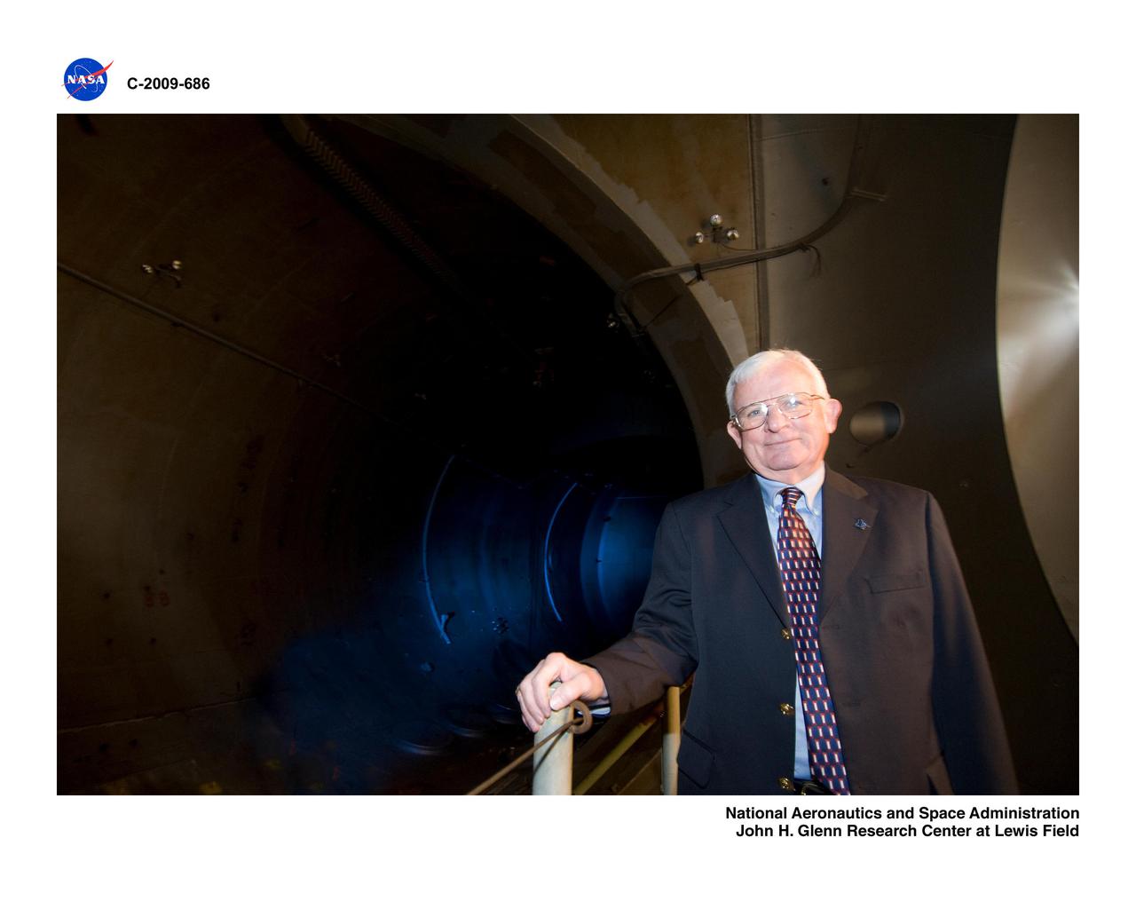
Former Center Director, Larry Ross, in the Altitude Wind Tunnel, AWT

These compressors inside the Refrigeration Building at the National Advisory Committee for Aeronautics (NACA) Aircraft Engine Research Laboratory were used to generate cold temperatures in the Altitude Wind Tunnel (AWT) and Icing Research Tunnel. The AWT was a large facility that simulated actual flight conditions at high altitudes. The two primary aspects of altitude simulation are the reduction of the air pressure and the decrease of temperature. The Icing Research Tunnel was a smaller facility in which water droplets were added to the refrigerated air stream to simulate weather conditions that produced ice buildup on aircraft. The military pressured the NACA to complete the tunnels quickly so they could be of use during World War II. The NACA engineers struggled with the design of this refrigeration system, so Willis Carrier, whose Carrier Corporation had pioneered modern refrigeration, took on the project. The Carrier engineers devised the largest cooling system of its kind in the world. The system could lower the tunnels’ air temperature to –47⁰ F. The cooling system was powered by 14 Carrier and York compressors, seen in this photograph, which were housed in the Refrigeration Building between the two wind tunnels. The compressors converted the Freon 12 refrigerant into a liquid. The refrigerant was then pumped into zig-zag banks of cooling coils inside the tunnels’ return leg. The Freon absorbed heat from the airflow as it passed through the coils. The heat was transferred to the cooling water and sent to the cooling tower where it was dissipated into the atmosphere.
Men stand in front of turning vanes inside the Altitude Wind Tunnel (AWT) at the National Advisory Committee for Aeronautics (NACA) Aircraft Engine Research Laboratory. The AWT was the only wind tunnel capable of testing full-size aircraft engines in simulated altitude conditions. A large wooden drive fan, located on the other side of these vanes, created wind speeds up to 500 miles per hour. The drive shaft connected the fan to the induction motor located in an adjacent building. Turning vanes were located in each corner of the rectangular tunnel to straighten the airflow and direct it around the corners. This set of vanes was located in the 31-foot-diameter southeast corner of the tunnel. These elliptical panels consisted of 36 to 42 vertical vanes that were supported by three horizontal supports. The individual vanes were 2.5 feet long and half-moon shaped. The panel of vanes was affixed to the curved corner rings of the tunnel. Each set of turning vanes had a moveable vane in the middle of the lower level for personnel access. Each set of vanes took weeks to assemble before they were installed during the summer of 1943. This publicity photograph was taken just weeks after the tunnel became operational in February 1944.
Construction workers install the drive motor for the Altitude Wind Tunnel (AWT) in the Exhauster Building at the National Advisory Committee for Aeronautics (NACA) Aircraft Engine Research Laboratory. The AWT was capable of operating full-scale engines in air density, speed, and temperature similar to that found at high altitudes. The tunnel could produce wind speeds up to 500 miles per hour through a 20-foot-diameter test section at the standard operating altitude of 30,000 feet. The airflow was created by a large wooden fan near the tunnel’s southeast corner. This photograph shows the installation of the 18,000-horsepower drive motor inside the adjoining Exhauster Building in July 1943. The General Electric motor, whose support frame is seen in this photograph, connected to a drive shaft that extended from the building, through the tunnel shell, and into a 12-bladed, 31-foot-diameter spruce wood fan. Flexible couplings on the shaft allowed for the movement of the shell. The corner of the Exhauster Building was built around the motor after its installation. The General Electric induction motor could produce 10 to 410 revolutions per minute and create wind speeds up to 500 miles per hour, or Mach 0.63, at 30,000 feet. The AWT became operational in January 1944 and tested piston, turbojet and ramjet engines for nearly 20 years.
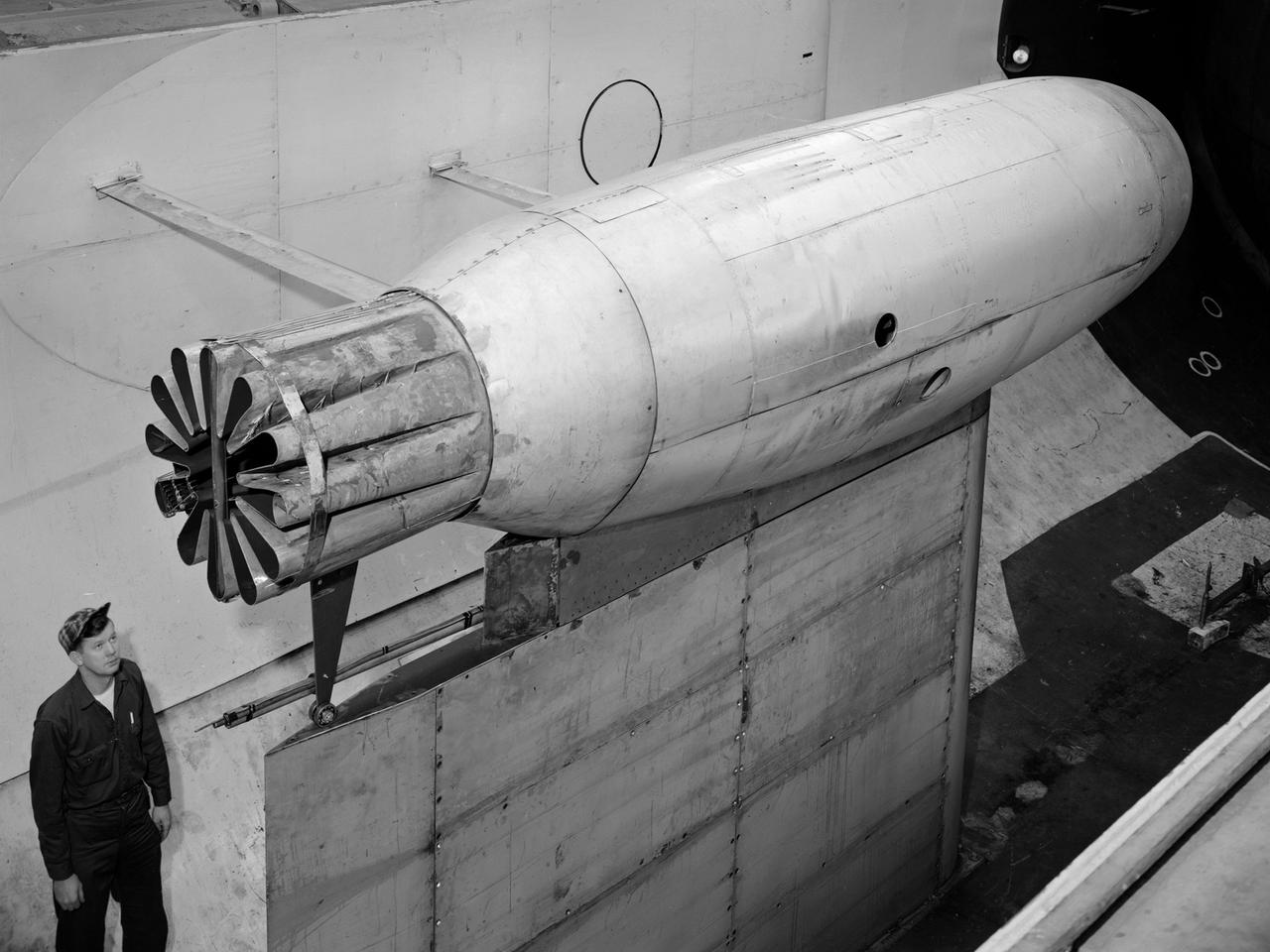
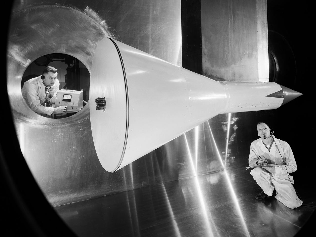
A mechanic at the National Aeronautics and Space Administration (NASA) Lewis Research Center prepares the inverted base of a Mercury capsule for a test of its posigrade retrorockets inside the Altitude Wind Tunnel. In October 1959 NASA’s Space Task Group allocated several Project Mercury assignments to Lewis. The Altitude Wind Tunnel was modified to test the Atlas separation system, study the escape tower rocket plume, train astronauts to bring a spinning capsule under control, and calibrate the capsule’s retrorockets. The turning vanes, makeup air pipes, and cooling coils were removed from the wide western end of the tunnel to create a 51-foot diameter test chamber. The Mercury capsule had a six-rocket retro-package affixed to the bottom of the capsule. Three of these were posigrade rockets used to separate the capsule from the booster and three were retrograde rockets used to slow the capsule for reentry into the earth’s atmosphere. Performance of the retrorockets was vital since there was no backup system. Qualification tests of the retrorockets began in April 1960 on a retrograde thrust stand inside the southwest corner of the Altitude Wind Tunnel. These studies showed that a previous issue concerning the delayed ignition of the propellant had been resolved. Follow-up test runs verified reliability of the igniter’s attachment to the propellant. In addition, the capsule’s retrorockets were calibrated so they would not alter the capsule’s attitude when fired.
The Altitude Wind Tunnel (AWT) during one of its overnight runs at the National Advisory Committee for Aeronautics (NACA) Aircraft Engine Research Laboratory in Cleveland, Ohio. The AWT was run during night hours so that its massive power loads were handled when regional electric demands were lowest. At the time the AWT was among the most complex wind tunnels ever designed. In order to simulate conditions at high altitudes, NACA engineers designed innovative new systems that required tremendous amounts of electricity. The NACA had an agreement with the local electric company that it would run its larger facilities overnight when local demand was at its lowest. In return the utility discounted its rates for the NACA during those hours. The AWT could produce wind speeds up to 500 miles per hour through its 20-foot-diameter test section at the standard operating altitude of 30,000 feet. The airflow was created by a large fan that was driven by an 18,000-horsepower General Electric induction motor. The altitude simulation was accomplished by large exhauster and refrigeration systems. The cold temperatures were created by 14 Carrier compressors and the thin atmosphere by four 1750-horsepower exhausters. The first and second shifts usually set up and broke down the test articles, while the third shift ran the actual tests. Engineers would often have to work all day, then operate the tunnel overnight, and analyze the data the next day. The night crew usually briefed the dayshift on the tests during morning staff meetings.
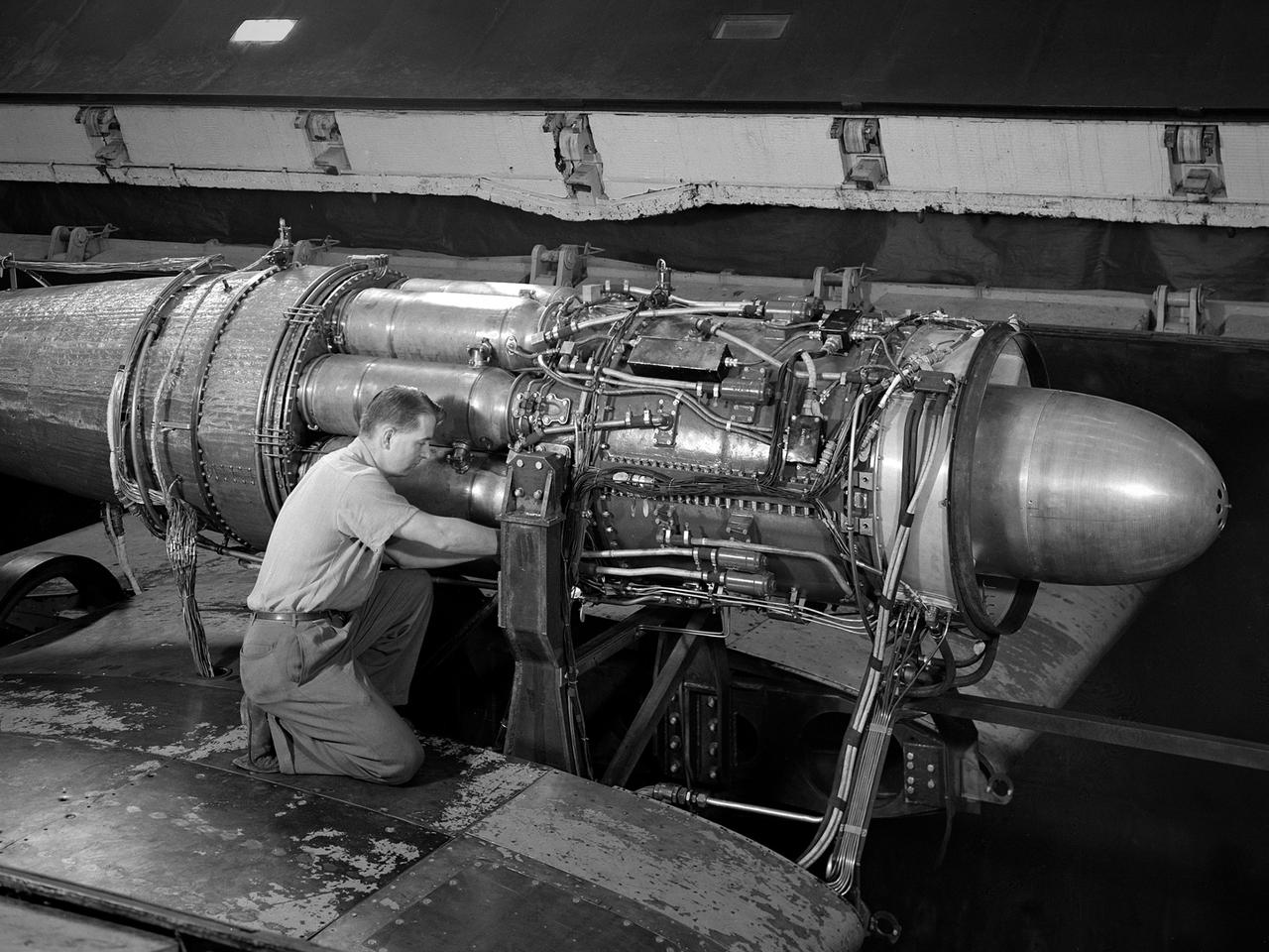
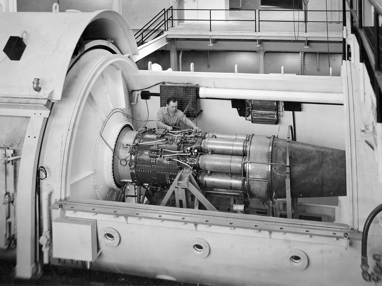
A Rolls Royce Avon RA-14 engine was tested in the Altitude Wind Tunnel at the National Advisory Committee for Aeronautics’ (NACA) Lewis Flight Propulsion Laboratory. The Avon RA-14 engine was a 16-stage axial-flow compressor turbojet capable of producing 9,500 pounds of thrust. The Avon replaced Rolls Royce’s successful Nene engine in 1950 and remained in service until 1974. It was one of several British engines studied in the tunnel during the 1950s. The Altitude Wind Tunnel went through a series of modifications in 1951 to increase its capabilities. An annex was attached to the Exhauster Building to house three new Ingersoll-Rand compressors. The wooden blades on the tunnel’s 31-foot diameter fan were replaced, a pump house and exhaust cooler were constructed underneath the tunnel, and two new cells were added to the cooling tower. The modified wind tunnel continued to analyze jet engines in the 1950s, although the engines, like the RA-14 seen here, were much more powerful than those studied several years before. Lewis researchers studied the RA-14 turbojet engine in the Altitude Wind Tunnel for 11 months in 1956. The engine was mounted on a stand capable of gauging engine thrust, and the tunnel’s air was ducted to the engine through a venturi and bellmouth inlet, seen in this photograph. The initial studies established the engine’s performance characteristics with a fixed-area nozzle and its acceleration characteristics. The researchers also used the tunnel to investigate windmilling of the compressor blades, restarting at high altitudes, and the engine’s performance limits at altitude.
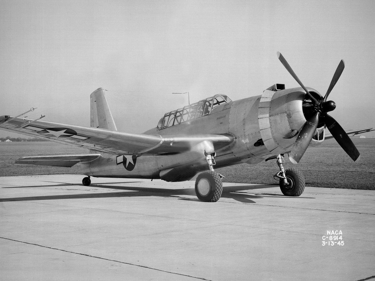
A 3670-horsepower Armstrong-Siddeley Python turboprop being prepared for tests in the Altitude Wind Tunnel at the National Advisory Committee for Aeronautics (NACA) Lewis Flight Propulsion Laboratory. In 1947 Lewis researcher Walter Olsen led a group of representatives from the military, industry, and the NACA on a fact finding mission to investigate the technological progress of British turbojet manufacturers. Afterwards several British engines, including the Python, were brought to Cleveland for testing in Lewis’s altitude facilities. The Python was a 14-stage axial-flow compressor turboprop with a fixed-area nozzle and contra-rotating propellers. Early turboprops combined the turbojet and piston engine technologies. They could move large quantities of air so required less engine speed and thus less fuel. This was very appealing to the military for some applications. The military asked the NACA to compare the Python’s performance at sea to that at high altitudes. The NACA researchers studied the Python in the Altitude Wind Tunnel from July 1949 through January 1950. It was the first time the tunnel was used to study an engine with the sole purpose of learning about, not improving it. They analyzed the engine’s dynamic response using a frequency response method at altitudes between 10,000 to 30,000 feet. Lewis researchers found that they could predict the dynamic response characteristics at any altitude from the data obtained from any other specific altitude. This portion of the testing was completed during a single test run.
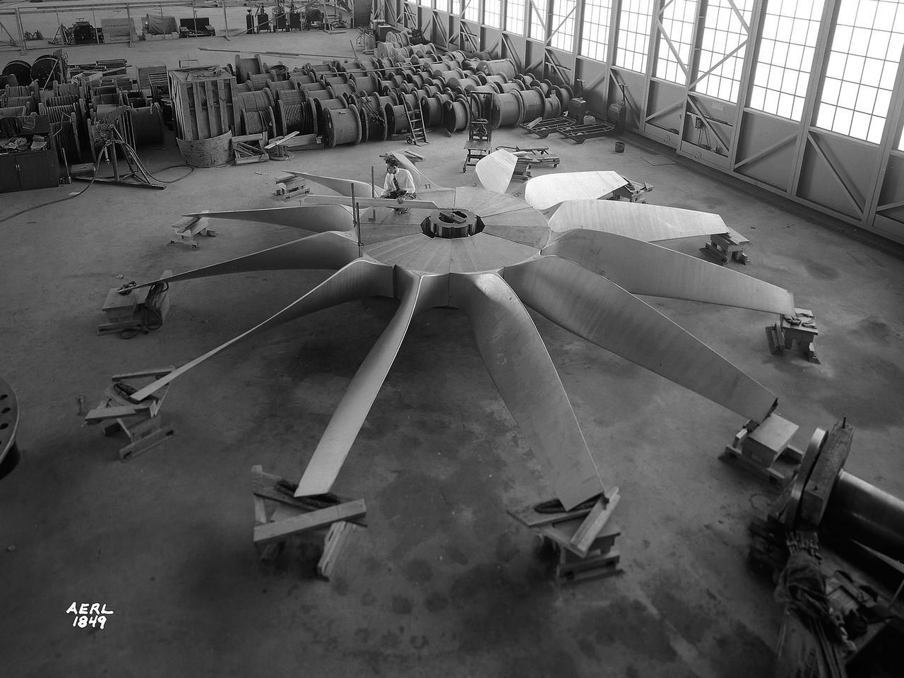
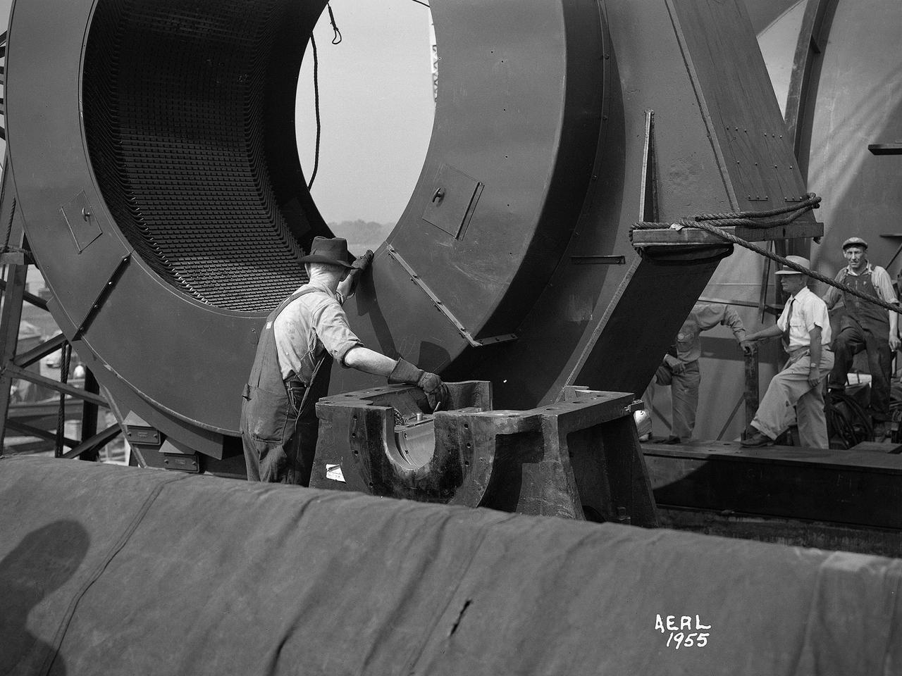
National Advisory Committee for Aeronautics (NACA) engineers assembled the Altitude Wind Tunnel’s (AWT) large wooden drive fan inside the hangar at the Aircraft Engine Research Laboratory. When it was built at the in the early 1940s the AWT was among the most complex test facilities ever designed. It was the first wind tunnel capable of operating full-scale engines under realistic flight conditions. This simulation included the reduction of air temperature, a decrease in air pressure, and the creation of an airstream velocity of up to 500 miles per hour. The AWT was constructed in 1942 and 1943. This photograph shows NACA engineers Lou Hermann and Jack Aust assembling the tunnel’s drive fan inside the hangar. The 12-bladed, 31-foot-diameter spruce wood fan would soon be installed inside the wind tunnel to create the high-speed airflow. This massive propeller was designed and constructed by the engine lab's design team at Langley Field. John Breisch, a Langley technician with several years of wind tunnel installation experience, arrived in Cleveland at the time of this photograph to supervise the fan assembly inside the hangar. He would return several weeks later to oversee the actual installation in the tunnel. The fan was driven at 410 revolutions per minute by an 18,000-horsepower General Electric induction motor that was located in the rear corner of the Exhauster Building. An extension shaft connected the motor to the fan. A bronze screen protected the fan against damage from failed engine parts sailing through the tunnel. Despite this screen the blades did become worn or cracked over time and had to be replaced. An entire new fan was installed in 1951.
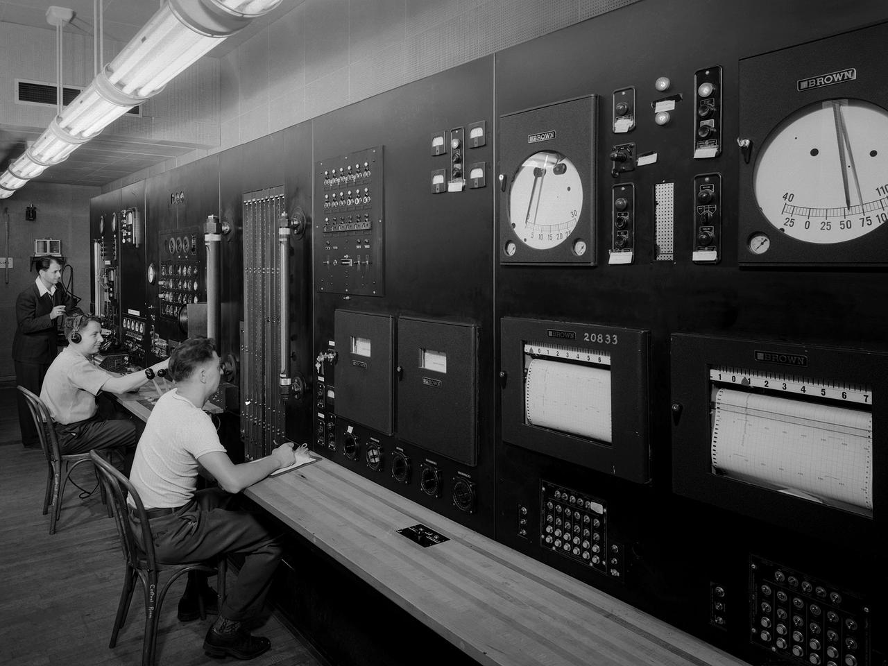
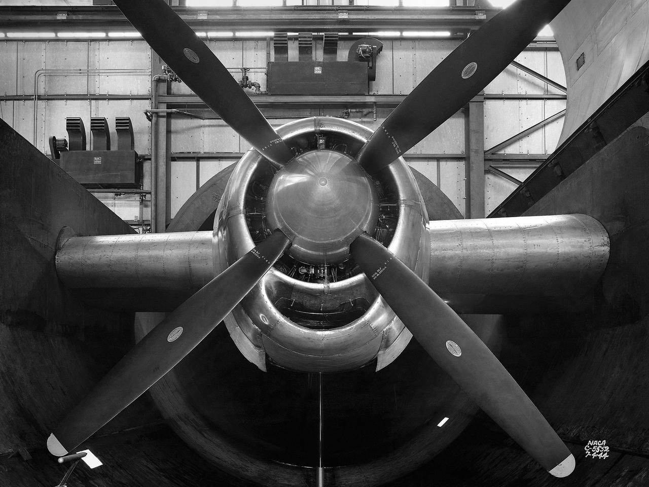
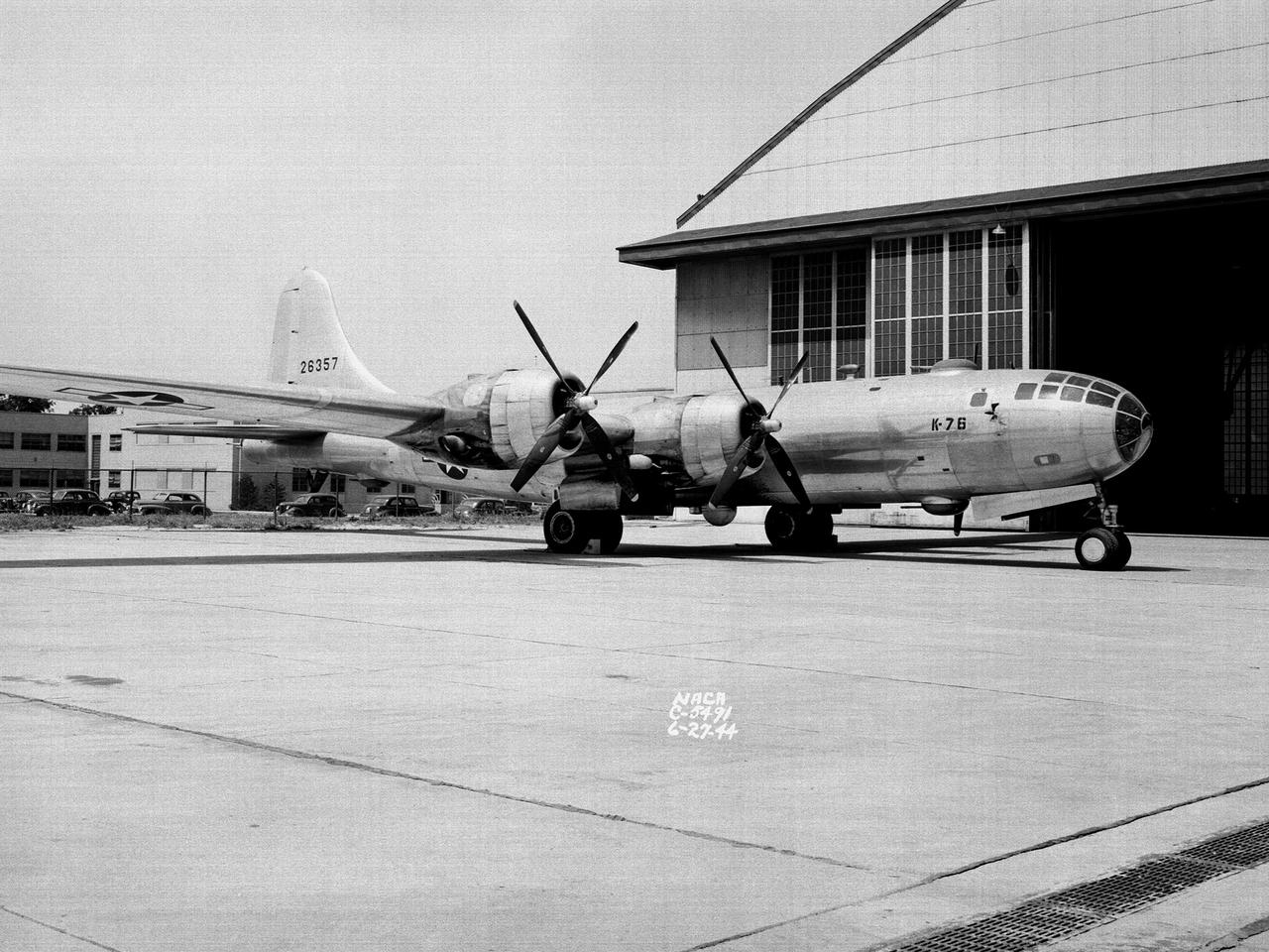
Operators in the control room for the Altitude Wind Tunnel at the National Advisory Committee for Aeronautics (NACA) Aircraft Engine Research Laboratory remotely operate a Wright R–3350 engine in the tunnel’s test section. Four of the engines were used to power the B–29 Superfortress, a critical weapon in the Pacific theater during World War II. The wind tunnel, which had been in operation for approximately six months, was the nation’s only wind tunnel capable of testing full-scale engines in simulated altitude conditions. The soundproof control room was used to operate the wind tunnel and control the engine being run in the test section. The operators worked with assistants in the adjacent Exhauster Building and Refrigeration Building to manage the large altitude simulation systems. The operator at the center console controlled the tunnel’s drive fan and operated the engine in the test section. Two sets of pneumatic levers near his right forearm controlled engine fuel flow, speed, and cooling. Panels on the opposite wall, out of view to the left, were used to manage the combustion air, refrigeration, and exhauster systems. The control panel also displayed the master air speed, altitude, and temperature gauges, as well as a plethora of pressure, temperature, and airflow readings from different locations on the engine. The operator to the right monitored the manometer tubes to determine the pressure levels. Despite just being a few feet away from the roaring engine, the control room remained quiet during the tests.
New wooden fan blades being prepared for installation in the Altitude Wind Tunnel at the National Advisory Committee for Aeronautics (NACA) Lewis Flight Propulsion Laboratory. The facility underwent a major upgrade in 1951 to increase its operating capacities in order to handle the new, more powerful turbojet engines being manufactured in the 1950s. The fan blades were prepared in the shop area, seen in this photograph, before being lowered through a hole in the tunnel and attached to the drive shaft. A new drive bearing and tail faring were also installed on the fan as part of this rehab project. A 12-bladed 31-foot-diameter spruce wood fan generated the 300 to 500 mile-per-hour airflow through the tunnel. An 18,000-horsepower General Electric induction motor located in the rear corner of the Exhauster Building drove the fan at 410 revolutions per minute. An extension shaft, sealed in the tunnel’s shell with flexible couplings that allowed for the movement of the shell, connected the motor to the fan. A bronze screen secured to the turning vanes protected the fan against damage from any engine parts sailing through the tunnel. Despite this screen the blades did become worn or cracked over time and had to be replaced.
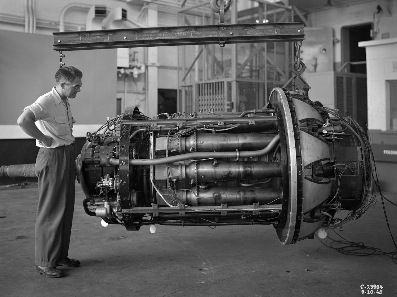
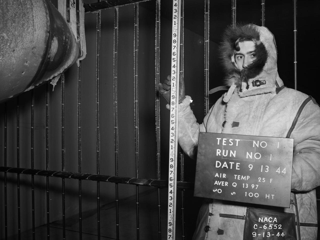
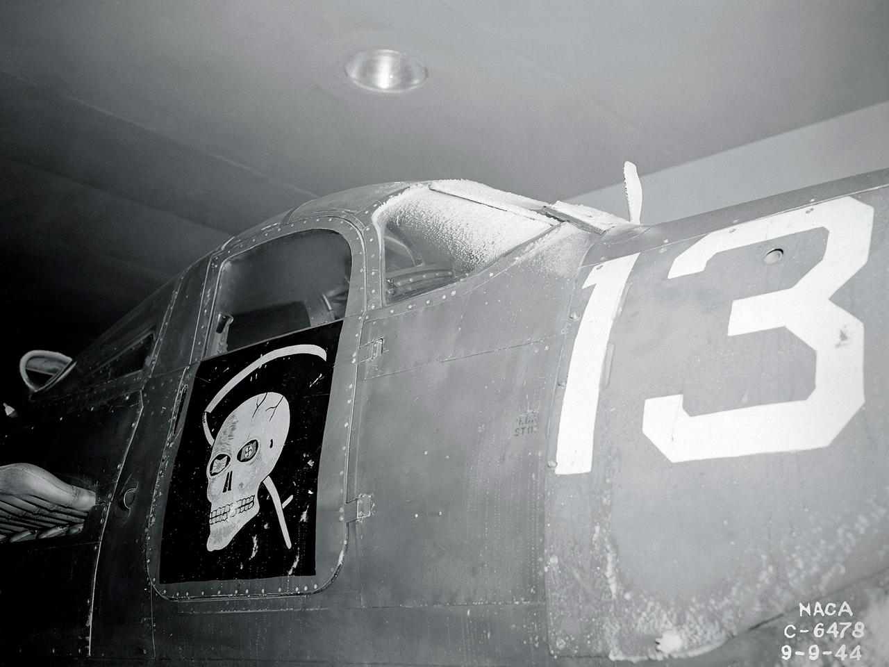
The Westinghouse 19XB turbojet seen from the side in the Altitude Wind Tunnel (AWT) test section at the National Advisory Committee for Aeronautics (NACA) Aircraft Engine Research Laboratory. Westinghouse started the development of a series of relatively small axial-flow turbojets for the Navy shortly after Pearl Harbor. In 1943 the 19A engine became both the first operational US-designed jet engine and the only U.S. turbojet incorporated into an aircraft during the war in Europe. In March 1943 Westinghouse agreed to create an improved six-stage 1400-pound thrust version, the 19B. The engine underwent its first test run a year later in March 1944. Almost immediately the navy agreed to Westinghouse’s proposal for the even larger 10-stage, 1600-pound-thrust 19XB prototype. By July 1944 the navy had contracted with the NACA for the testing of both engines in the AWT. The tunnel was the nation’s only facility for studying full-scale engines in simulated altitude conditions. The wind tunnel investigations, which began on September 9, 1944, revealed the superiority of the previously untested 19XB over the 19B. The 19B engines failed to restart consistently and suffered combustion blowouts above 17,000 feet. The 19XB, however, performed well and restarted routinely at twice that altitude. Two months later on January 26, 1945, two 19Bs powered a McDonnell XFD–1 Phantom, the US Navy’s first fighter jet, on its initial flight. Following its exceptional performance in the AWT, the 19XB engines soon replaced the 19Bs in the Phantom.
The Altitude Wind Tunnel (AWT) was the National Advisory Committee for Aeronautics (NACA) Aircraft Engine Research Laboratory’s largest and most important test facility in the 1940s. The AWT employed massive cooling and exhaust systems to simulate conditions found at high altitudes. The facility was originally designed to test large piston engines in a simulated flight environment. The introduction of the turbojet during the tunnel’s construction, however, changed the facility’s focus before it became operational. Its first test program was a study of the Bell YP–59A Airacomet and its General Electric I–16 turbojets. The Airacomet was the United States’ first attempt to build a jet aircraft. 1600-horsepower centrifugal engines based on an early design by British engineer Frank Whittle were incorporated into an existing Bell airframe. In October 1942 the Airacomet was secretly test flown in the California desert. The aircraft’s performance was limited, however, and the NACA was asked to study the engines in the AWT. The wind tunnel’s 20-foot-diameter test section was large enough to accommodate entire aircraft with its wing tips and tail removed. The I-16 engines were studied exhaustively in early 1944. They first analyzed the engines in their original configuration and then implemented a boundary layer removal duct, a new nacelle inlet, and new cooling seals. Tests of the modified version showed that the improved distribution of airflow increased the I–16’s performance by 25 percent. The Airacomet never overcame some of its inherent design issues, but the AWT went on to study nearly every emerging US turbojet model during the next decade.
A General Electric TG-100A seen from the rear in the test section of the Altitude Wind Tunnel at the National Advisory Committee for Aeronautics (NACA) Lewis Flight Propulsion Laboratory in Cleveland, Ohio. The Altitude Wind Tunnel was used to study almost every model of US turbojet that emerged in the 1940s, as well as some ramjets and turboprops. In the early 1940s the military was interested in an engine that would use less fuel than the early jets but would keep up with them performance-wise. Turboprops seemed like a plausible solution. They could move a large volume of air and thus required less engine speed and less fuel. Researchers at General Electric’s plant in Schenectady, New York worked on the turboprop for several years in the 1930s. They received an army contract in 1941 to design a turboprop engine using an axial-flow compressor. The result was the 14-stage TG-100, the nation's first turboprop aircraft engine. Development of the engine was slow, however, and the military asked NACA Lewis to analyze the engine’s performance. The TG-100A was tested in the Altitude Wind Tunnel and it was determined that the compressors, combustion chamber, and turbine were impervious to changes in altitude. The researchers also established the optimal engine speed and propeller angle at simulated altitudes up to 35,000 feet. Despite these findings, development of the TG-100 was cancelled in May 1947. Twenty-eight of the engines were produced, but they were never incorporated into production aircraft.
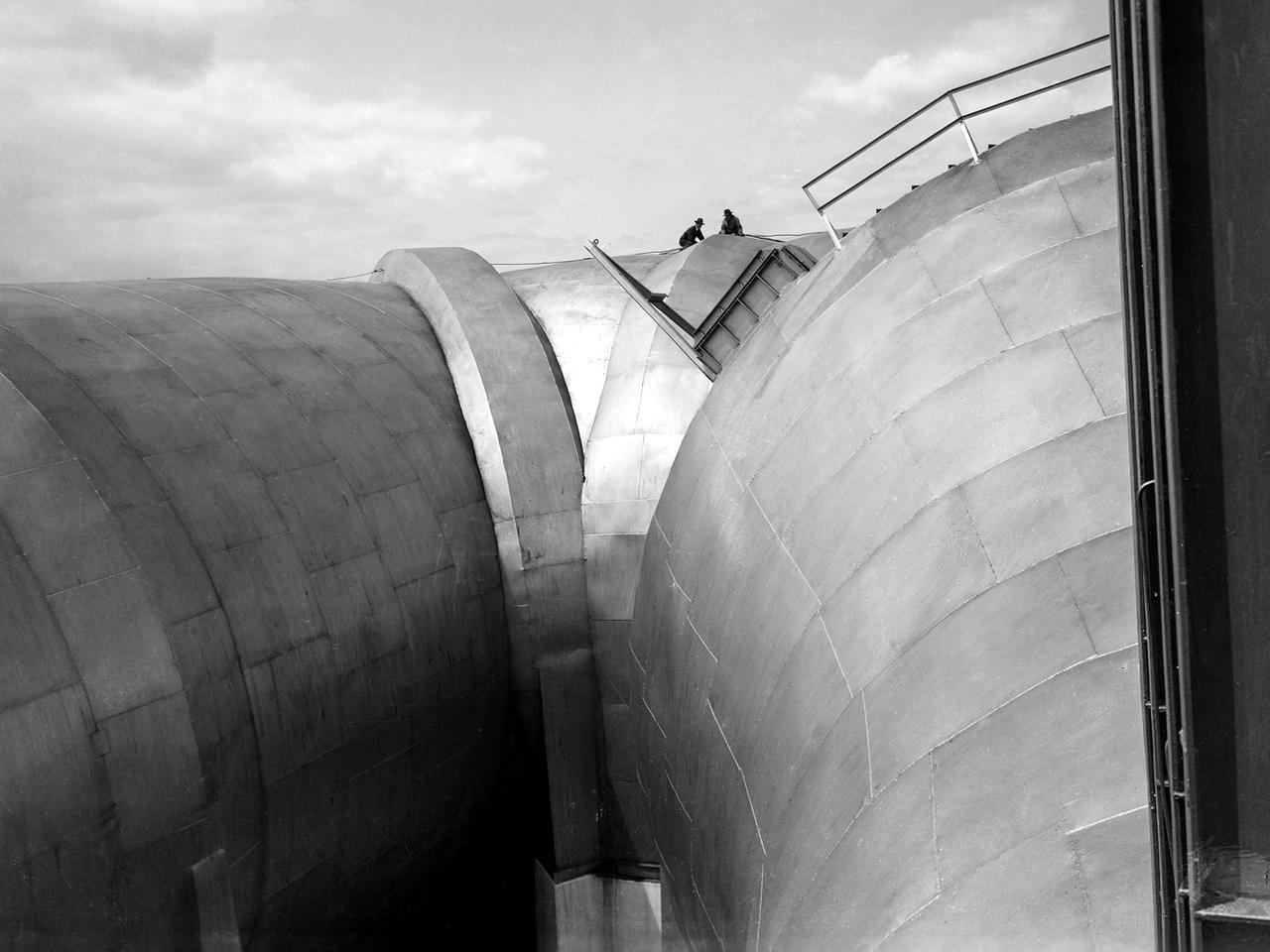
Two men on top of the Altitude Wind Tunnel (AWT) at the National Advisory Committee for Aeronautics (NACA) Aircraft Engine Research Laboratory. The tunnel was a massive rectangular structure, which for years provided one of the highest vantage points on the laboratory. The tunnel was 263 feet long on the north and south legs and 121 feet long on the east and west sides. The larger west end of the tunnel, seen here, was 51 feet in diameter. The east side of the tunnel was 31 feet in diameter at the southeast corner and 27 feet in diameter at the northeast. The throat section, which connected the northwest corner to the test section, narrowed sharply from 51 to 20 feet in diameter. The AWT’s altitude simulation required temperature and pressure fluctuations that made the design of the shell more difficult than other tunnels. The simultaneous decrease in both pressure and temperature inside the facility produced uneven stress loads, particularly on the support rings. The steel used in the primary tunnel structure was one inch thick to ensure that the shell did not collapse as the internal air pressure was dropped to simulate high altitudes. It was a massive amount of steel considering the World War II shortages. The shell was covered with several inches of fiberglass insulation to retain the refrigerated air and a thinner outer steel layer to protect the insulation against the weather. A unique system of rollers was used between the shell and its support piers. These rollers allowed for movement as the shell expanded or contracted during the altitude simulations. Certain sections would move as much as five inches during operation.
The resolution of the Boeing B-29 Superfortress’ engine cooling problems was one of the Aircraft Engine Research Laboratory’s (AERL) key contributions to the World War II effort. The B-29 leapfrogged previous bombers in size, speed, and altitude capabilities. The B–29 was intended to soar above anti-aircraft fire and make pinpoint bomb drops onto strategic targets. Four Wright Aeronautical R-3350 engines powered the massive aircraft. The engines, however, frequently strained and overheated due to payload overloading. This resulted in a growing number of engine fires that often resulted in crashes. The military asked the NACA to tackle the overheating issue. Full-scale engine tests on a R–3350 engine in the Prop House demonstrated that a NACA-designed impeller increased the fuel injection system’s flow rate. Single-cylinder studies resolved a valve failure problem by a slight extension of the cylinder head, and researchers in the Engine Research Building combated uneven heating with a new fuel injection system. Investigations during the summer of 1944 in the Altitude Wind Tunnel, which could simulate flight conditions at high altitudes, led to reduction of drag and improved air flow by reshaping the cowling inlet and outlet. The NACA modifications were then flight tested on a B-29 bomber that was brought to the AERL.
A General Electric TG-180 turbojet installed in the Altitude Wind Tunnel at the National Advisory Committee for Aeronautics (NACA) Lewis Flight Propulsion Laboratory. In 1943 the military asked General Electric to develop an axial-flow jet engine which became the TG-180. The military understood that the TG-180 would not be ready during World War II but recognized the axial-flow compressor’s long-term potential. Although the engine was bench tested in April 1944, it was not flight tested until February 1946. The TG-180 was brought to the Altitude Wind Tunnel in 1945 for a series of investigations. The studies, which continued intermittently into 1948, analyzed an array of performance issues. NACA modifications steadily improved the TG-180’s performance, including the first successful use of an afterburner. The Lewis researchers studied a 29-inch diameter afterburner over a range of altitude conditions using several different types of flameholders and fuel systems. Lewis researchers concluded that a three-stage flameholder with its largest stage upstream was the best burner configuration. Although the TG-180 (also known as the J35) was not the breakthrough engine that the military had hoped for, it did power the Douglas D-558-I Skystreak to a world speed record on August 20, 1947. The engines were also used on the Republic F-84 Thunderjet and the Northrup F-89 Scorpion.
A Pratt and Whitney J57 engine is tested with a Greatex No.1 nozzle in the Altitude Wind Tunnel at the National Advisory Committee for Aeronautics (NACA) Lewis Flight Propulsion Laboratory. At the time the aircraft industry was preparing to introduce jet airliners to the nation’s airways. The noise produced by the large jet engines, however, posed a considerable problem for communities near airports. The NACA had formed a Special Subcommittee on Aircraft Noise to coordinate research on the issue. Preliminary tests showed that the source of the loudest noise was not the engine itself, but the mixing of the engine’s exhaust with the surrounding air in the atmosphere. The pressures resulting from this turbulence produced sound waves. Lewis researchers undertook a variety of noise-reduction studies involving engine design, throttling procedures, and noise suppressors. One of their first efforts focused on new types of nozzles to mix the exhaust with the surrounding air. The nozzles had a variety of shapes designed to slow down exhaust velocity before it combined with the air and thus decrease the noise. From January to May 1957 a Pratt and Whitney J57 engine was equipped with various shaped nozzles, as seen in this photograph, and run in simulated flight conditions in the Altitude Wind Tunnel. A number of nozzle configurations, including several multi-exit “organ pipe” designs, were created. It was found that the various nozzle types did reduce the noise levels, but they also reduced the aircraft’s thrust.
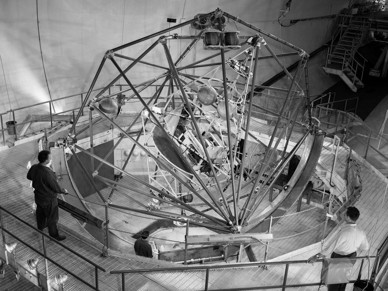
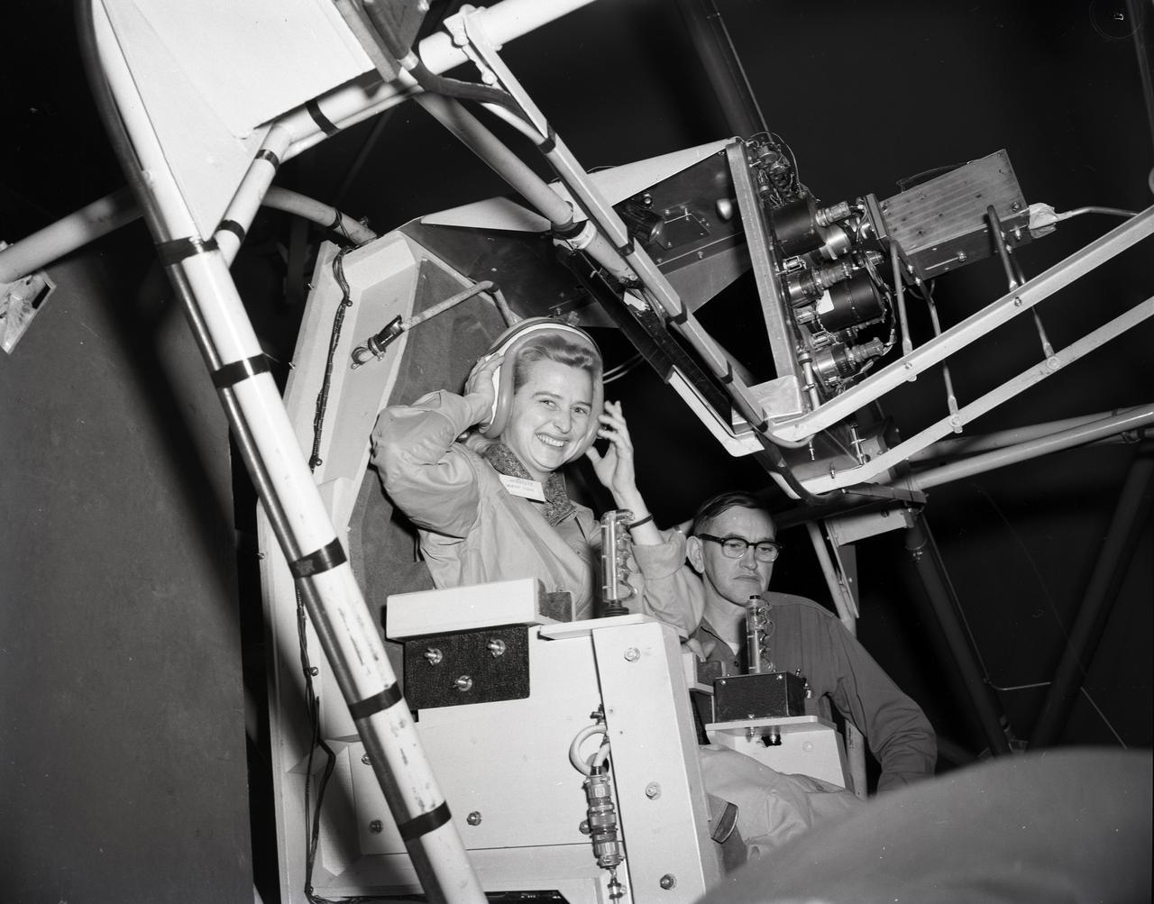
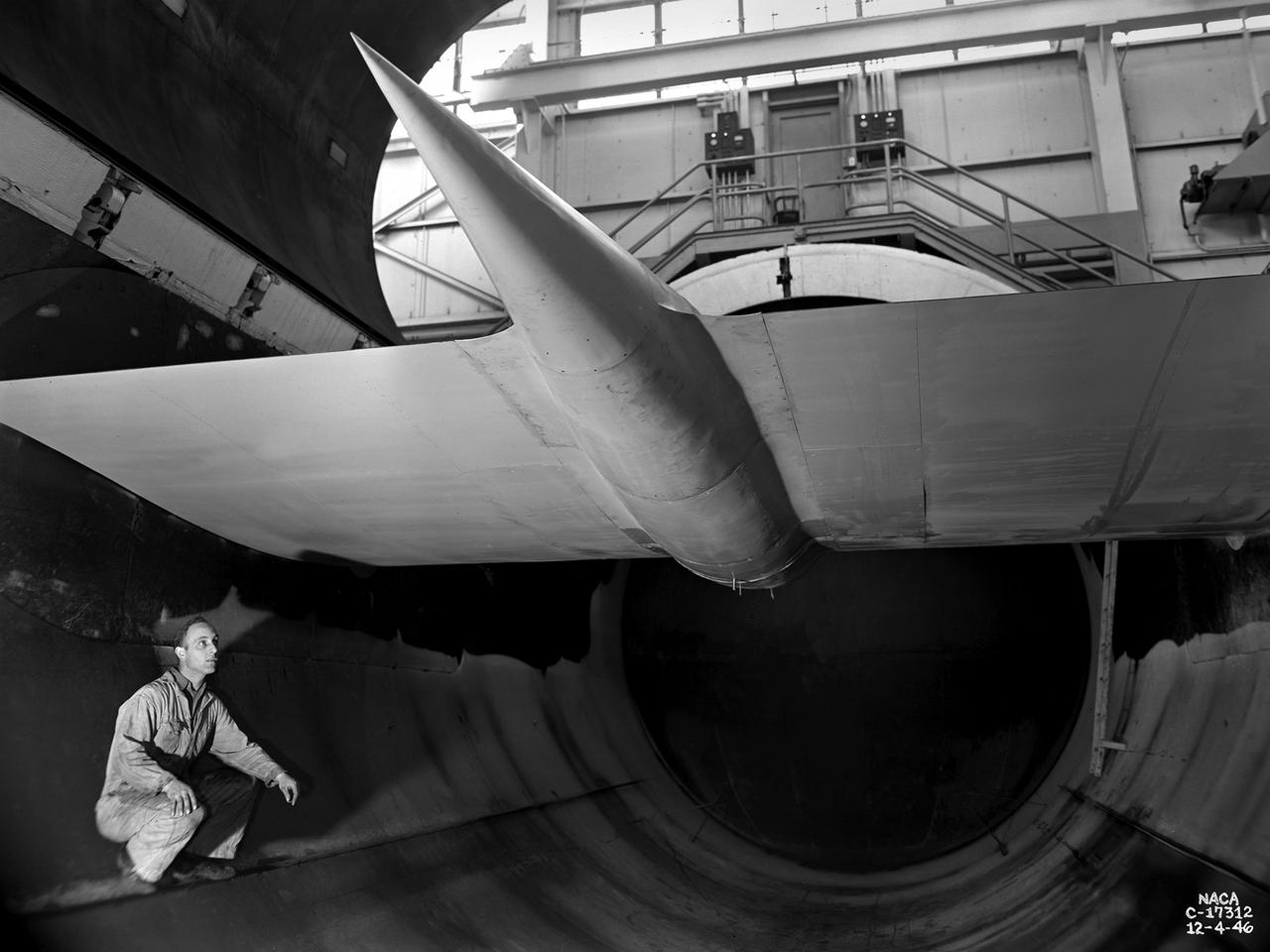
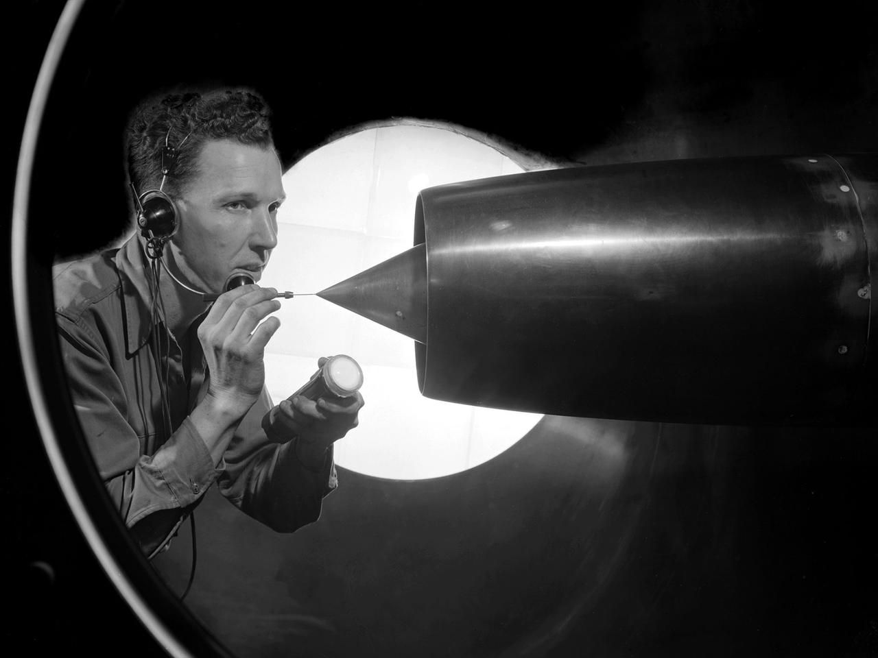
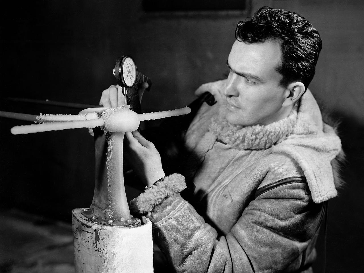
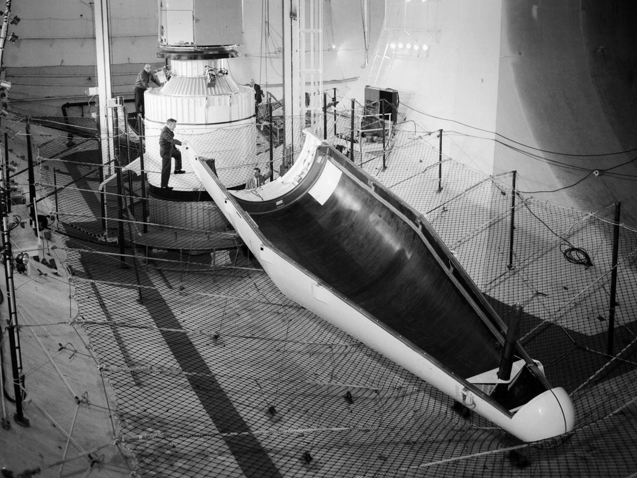
The Multi-Axis Space Test Inertial Facility (MASTIF) in the Altitude Wind Tunnel at the National Aeronautics and Space Administration (NASA) Lewis Research Center. Although the Mercury astronaut training and mission planning were handled by the Space Task Group at Langley Research Center, NASA Lewis played an important role in the program, beginning with the Big Joe launch. Big Joe was a singular attempt early in the program to use a full-scale Atlas booster and simulate the reentry of a mockup Mercury capsule without actually placing it in orbit. A unique three-axis gimbal rig was built inside Lewis’ Altitude Wind Tunnel to test Big Joe’s attitude controls. The control system was vital since the capsule would burn up on reentry if it were not positioned correctly. The mission was intended to assess the performance of the Atlas booster, the reliability of the capsule’s attitude control system and beryllium heat shield, and the capsule recovery process. The September 9, 1959 launch was a success for the control system and heatshield. Only a problem with the Atlas booster kept the mission from being a perfect success. The MASTIF was modified in late 1959 to train Project Mercury pilots to bring a spinning spacecraft under control. An astronaut was secured in a foam couch in the center of the rig. The rig then spun on three axes from 2 to 50 rotations per minute. Small nitrogen gas thrusters were used by the astronauts to bring the MASTIF under control.

An inlet duct lowered into the 20-foot diameter test section of the Altitude Wind Tunnel at the National Advisory Committee for Aeronautics (NACA) Lewis Flight Propulsion Laboratory. Engines and hardware were prepared in the facility’s shop area. The test articles were lifted by a two-rail Shaw box crane through the high-bay and the second-story test chamber before being lowered into the test section. Technicians then spent days or weeks hooking up the supply lines and data recording telemetry. The engines were mounted on wingspans that stretched across the test section. The wingtips attached to the balance frame’s trunnions, which could adjust the angle of attack. The balance frame included six devices that recorded data and controlled the engine. The measurements were visible in banks of manometer boards next to the control room. Photographs recorded the pressure levels in the manometer tubes, and the computing staff manually converted the data into useful measurements. A mechanical pulley system was used to raise and lower the tunnel’s large clamshell lid into place. The lid was sealed into place using hand-turned locks accessible from the viewing platform. The lid had viewing windows above and below the test article, which permitted the filming and visual inspection of the tests.
The secret test of the Bell YP–59A Airacomet in the spring of 1944 was the first investigation in the National Advisory Committee for Aeronautics (NACA) Aircraft Engine Research Laboratory’s new Altitude Wind Tunnel (AWT). The Airacomet, powered by two General Electric I–A centrifugal turbojets, was the first US jet aircraft. The Airacomet’s 290-miles per hour speed, however, was dwarfed by the German Messerschmitt Me-262 Schwalbe’s 540 miles per hour. In 1941 and 1942 General Electric built the first US jet engines based on technical drawings from British engineer Frank Whittle. Bell Aircraft was contracted to produce an airframe to incorporate the new engines. The result was the Bell XP–59A Airacomet. The aircraft made its first flight over Muroc Lake, California, on October 2, 1942. The aircraft continued to struggle over the next year and the NACA was asked to test it in the new AWT. A Bell YP–59A was flown from the Bell plant in Buffalo to Cleveland by Bob Stanley, who had piloted the first successful flight of the XP–59A at Muroc in 1942. The wing tips and tail were cut from the aircraft so that it would fit into the AWT’s test section. The study first analyzed the engines in their original configuration and then implemented a boundary layer removal duct, a new nacelle inlet, and new cooling seals. Tests of the modified version showed that the improved airflow distribution increased the I–16’s performance by 25 percent. Despite the improved speed, the aircraft was not stable enough to be used in combat, and the design was soon abandoned.
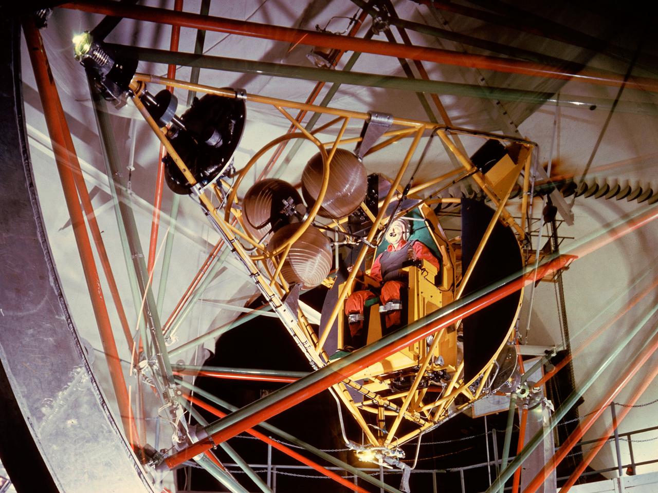
National Aeronautics and Space Administration (NASA) pilot Joe Algranti tests the Multi-Axis Space Test Inertia Facility (MASTIF) inside the Altitude Wind Tunnel while researcher Robert Miller looks on. The MASTIF was a three-axis rig with a pilot’s chair mounted in the center to train Project Mercury pilots to bring a spinning spacecraft under control. An astronaut was secured in a foam couch in the center of the rig. The rig then spun on three axes from 2 to 50 rotations per minute. Small nitrogen gas thrusters were used by the astronauts to bring the MASTIF under control. The device was originally designed in early 1959 without the chair and controllers. It was used by Lewis researchers to determine if the Lewis-designed autopilot system could rectify the capsule’s attitude following separation. If the control system failed to work properly, the heatshield would be out of place and the spacecraft would burn up during reentry. The system was flight tested during the September 1959 launch of the Lewis-assembled Big Joe capsule. The MASTIF was adapted in late 1959 for the astronaut training. NASA engineers added a pilot’s chair, a hand controller, and an instrument display to the MASTIF in order familiarize the astronauts with the sensations of an out-of-control spacecraft. NASA Lewis researcher James Useller and Algranti perfected and calibrated the MASTIF in the fall of 1959. In February and March 1960, the seven Project Mercury astronauts traveled to Cleveland to train on the MASTIF.

Altitude Wind Tunnel (AWT) construction: cutting tunnel
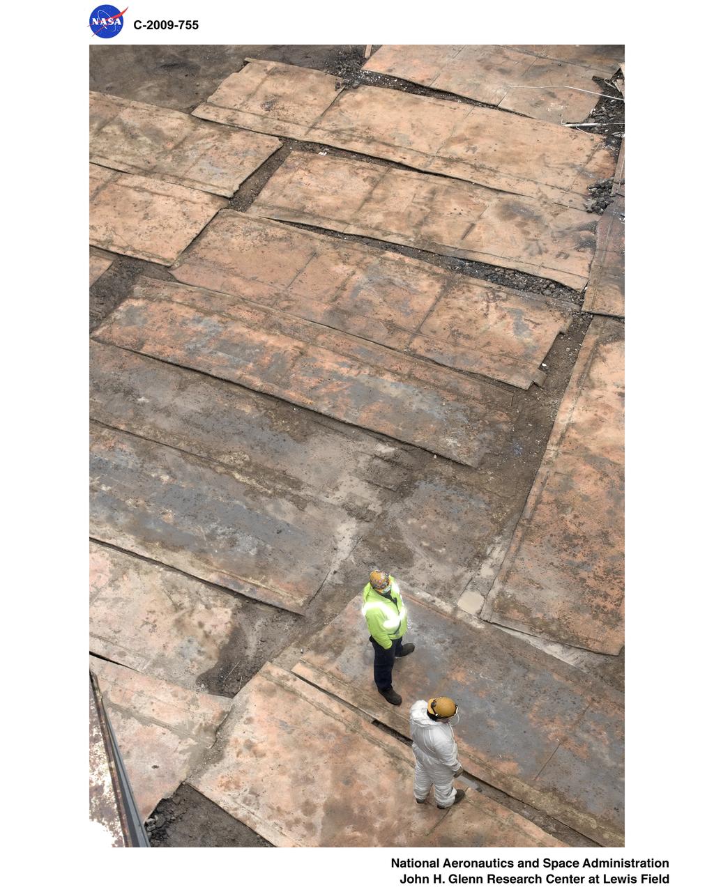
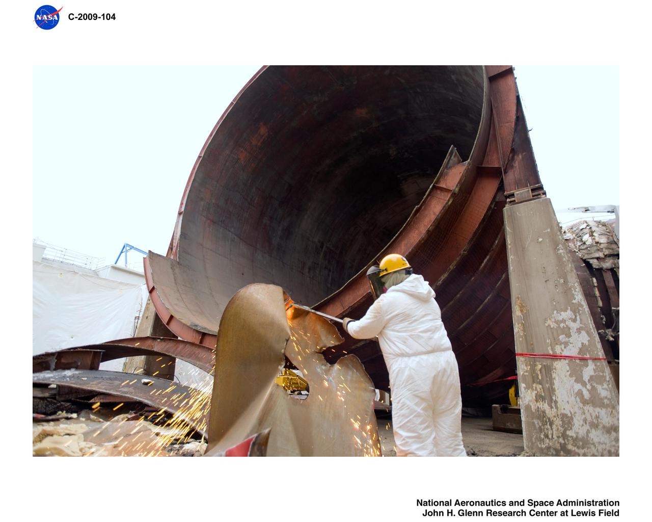
Altitude Wind Tunnel (AWT) Demolition
Altitude Wind Tunnel (AWT) Demolition
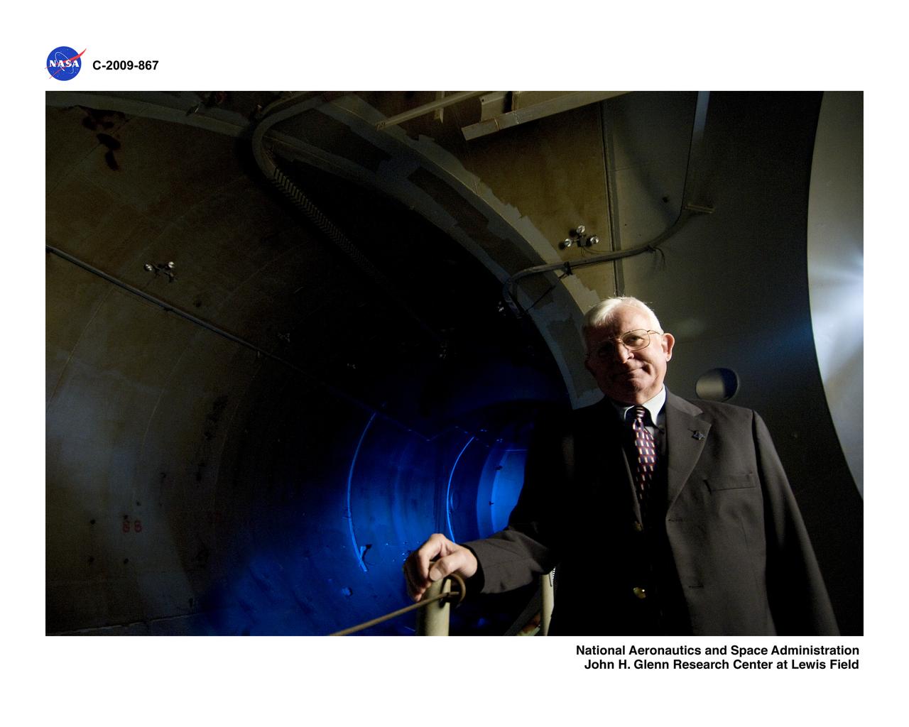
Altitude Wind Tunnel (AWT) Interviews
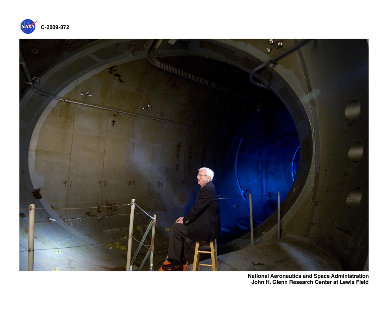
Altitude Wind Tunnel (AWT) Interviews
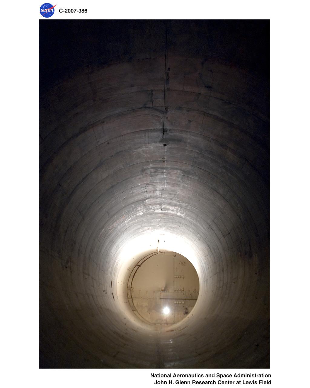
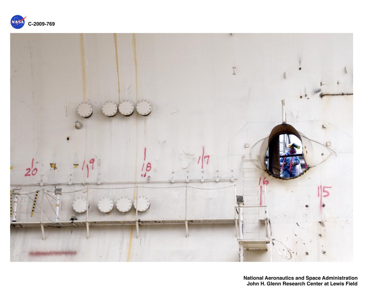
Altitude Wind Tunnel (AWT) interior pictures before demolition
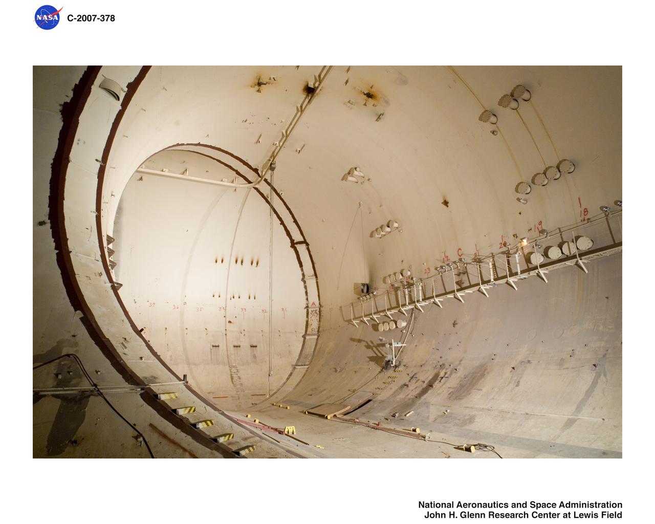
Altitude Wind Tunnel (AWT) interior pictures before demolition
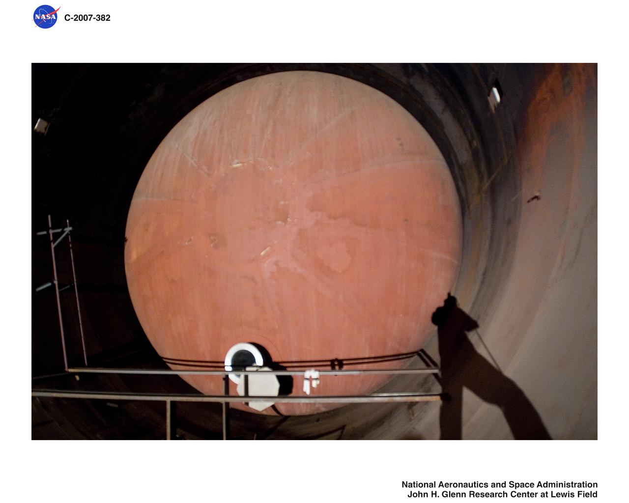
Altitude Wind Tunnel (AWT) interior pictures before demolition
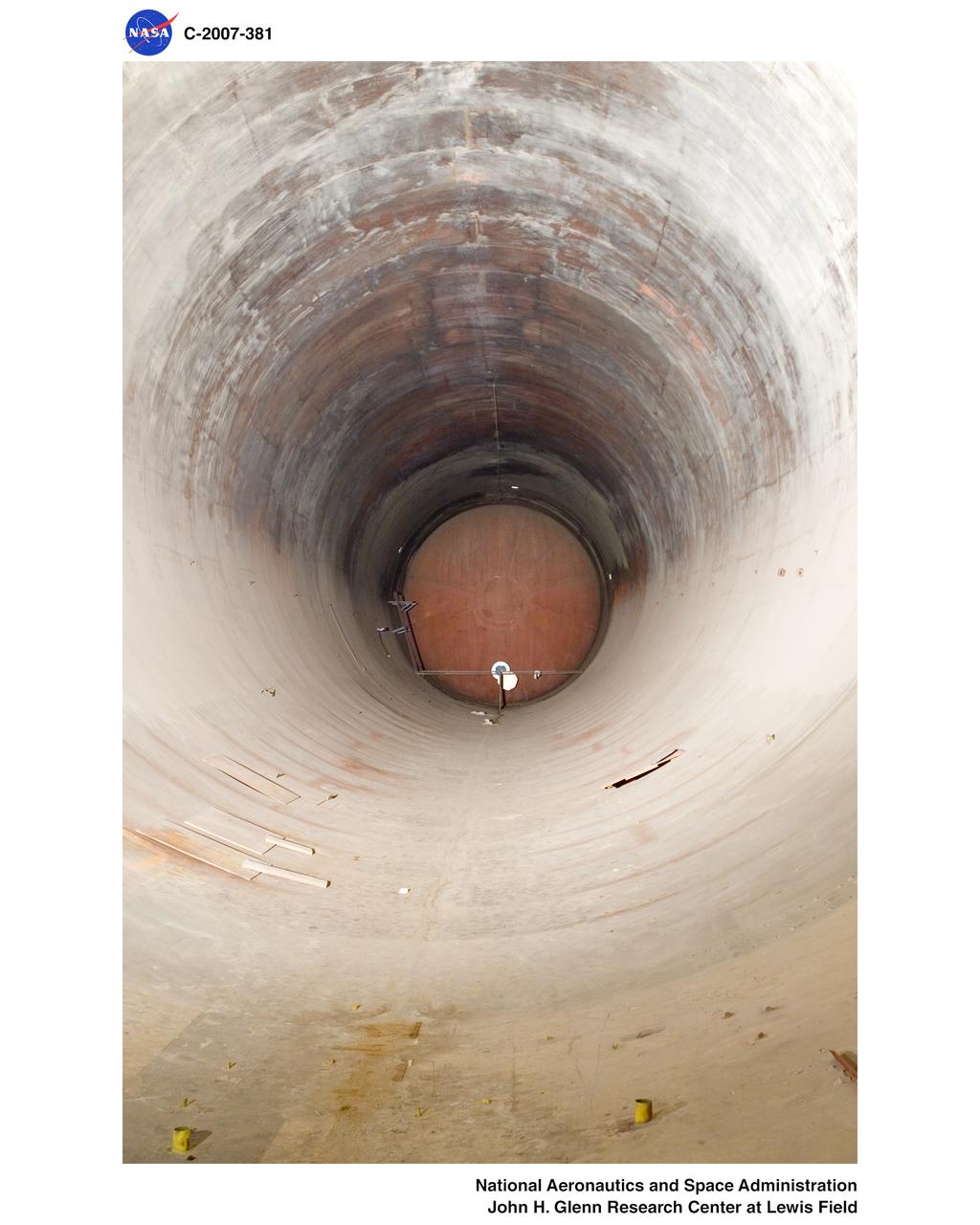
Altitude Wind Tunnel (AWT) interior pictures before demolition
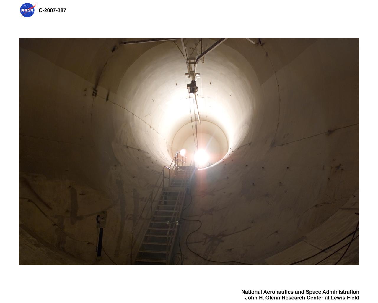
Altitude Wind Tunnel (AWT) interior pictures before demolition
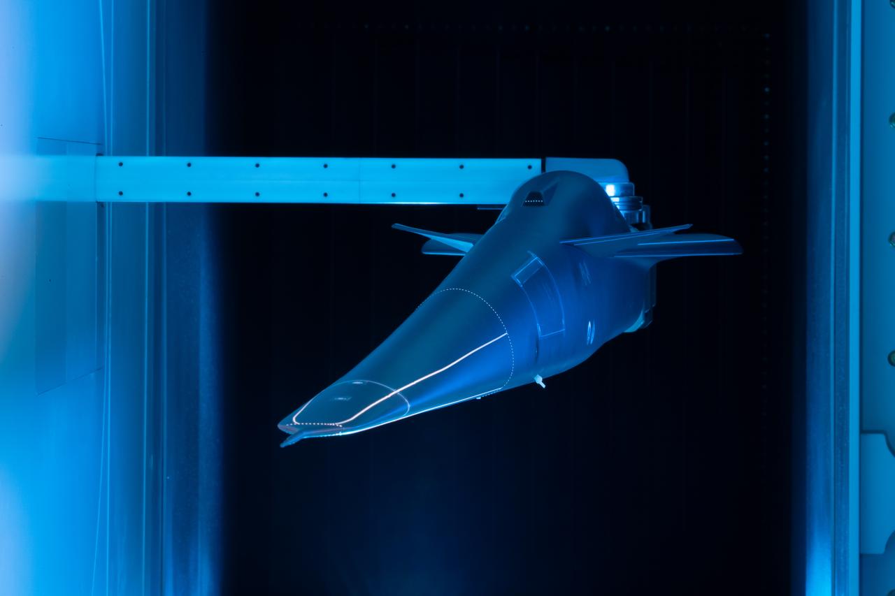
Event: Forebody and Nose - Windtunnel Testing A model of the X-59 forebody is shown in the Lockheed Martin Skunk Works’ wind tunnel in Palmdale, California. These tests gave the team measurements of wind flow angle around the aircraft’s nose and confirmed computer predictions made using computational fluid dynamics (CFD) software tools. The data will be fed into the aircraft flight control system to tell the pilot the aircraft’s altitude, speed and angle. This is part of NASA’s Quesst mission which plans to help enable supersonic air travel over land.
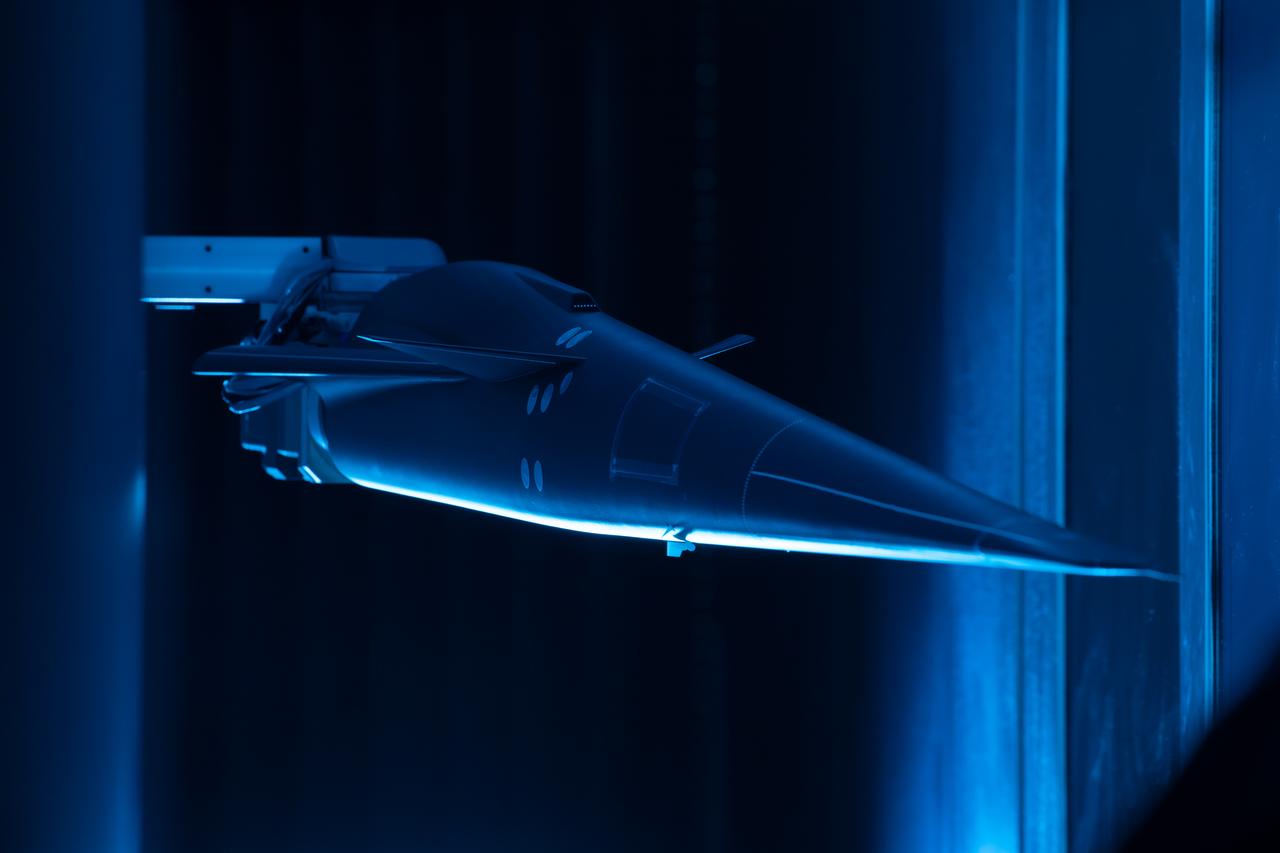
Event: Forebody and Nose - Windtunnel Testing A model of the X-59 forebody is shown in the Lockheed Martin Skunk Works’ wind tunnel in Palmdale, California. These tests gave the team measurements of wind flow angle around the aircraft’s nose and confirmed computer predictions made using computational fluid dynamics (CFD) software tools. The data will be fed into the aircraft flight control system to tell the pilot the aircraft’s altitude, speed and angle. This is part of NASA’s Quesst mission which plans to help enable supersonic air travel over land.
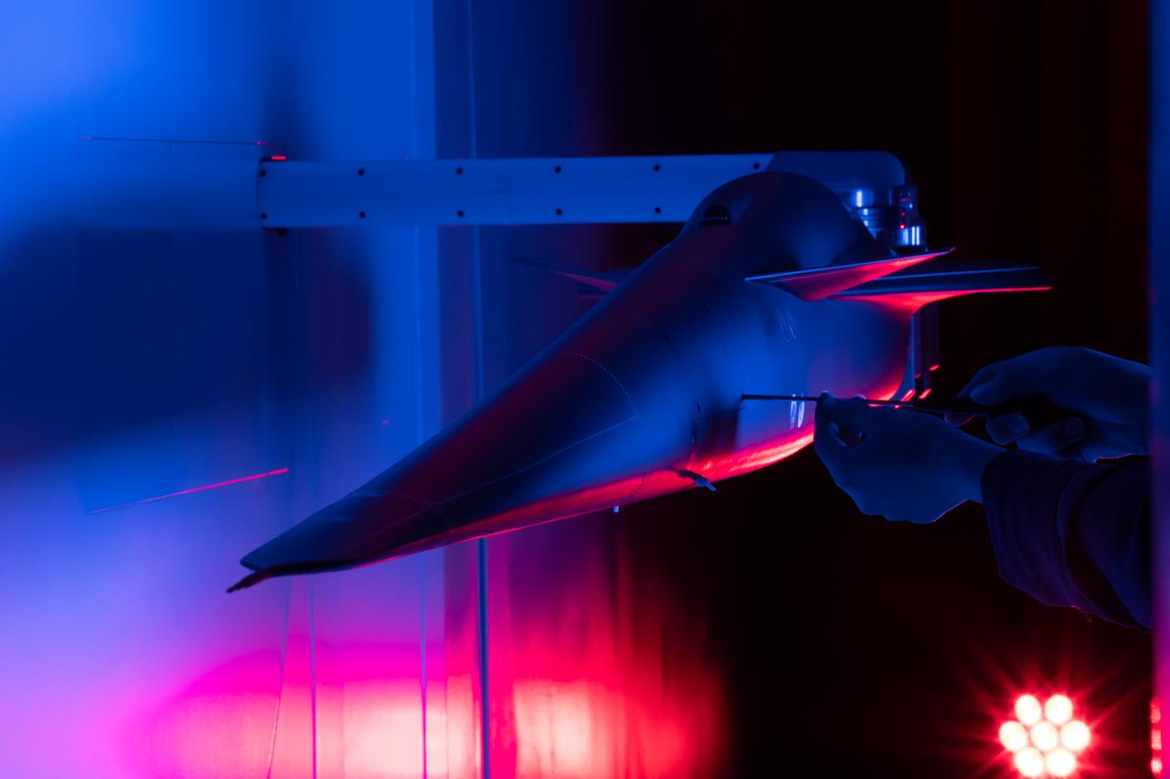
Event: Forebody and Nose - Windtunnel Testing A technician works on the X-59 model during testing in the low-speed wind tunnel at Lockheed Martin Skunk Works in Palmdale, California. These tests gave the team measurements of wind flow angle around the aircraft’s nose and confirmed computer predictions made using computational fluid dynamics (CFD) software tools. The data will be fed into the aircraft flight control system to tell the pilot the aircraft’s altitude, speed, and angle. This is part of NASA’s Quesst mission which plans to help enable supersonic air travel over land.
A technician at the National Advisory Committee for Aeronautics (NACA) Lewis Flight Propulsion Laboratory cleans the pitot tube on a 16-inch diameter ramjet in the 8- by 6-Foot Supersonic Wind Tunnel. Pitot tubes are a measurement device used to determine the flow velocity at a specific location in the air stream, not the average velocity of the entire wind stream. NACA Lewis was in the midst of a multi-year program to determine the feasibility of ramjets and design improvements that could be employed for all models. The advantage of the ramjet was its ability to process large volumes of combustion air, resulting in the burning of fuel at the optimal stoichiometric temperatures. This was not possible with turbojets. The higher the Mach number, the more efficient the ramjet operated. The 8- by 6 Supersonic Wind Tunnel had been in operation for just over one year when this photograph was taken. The facility was the NACA’s largest supersonic tunnel and the only facility capable of running an engine at supersonic speeds. The 8- by 6 tunnel was also equipped with a Schlieren camera system that captured the air flow gradient as it passes over the test setup. The ramjet tests in the 8- by 6 tunnel complemented the NACA Lewis investigations using aircraft, the Altitude Wind Tunnel and smaller supersonic tunnels. Researchers studied the ramjet’s performance at different speeds and varying angles -of -attack.

A Mercury capsule is mounted inside the Altitude Wind Tunnel for a test of its escape tower rockets at the National Aeronautics and Space Administration (NASA) Lewis Research Center. In October 1959 NASA’s Space Task Group allocated several Project Mercury assignments to Lewis. The Altitude Wind Tunnel was quickly modified so that its 51-foot diameter western leg could be used as a test chamber. The final round of tests in the Altitude Wind Tunnel sought to determine if the smoke plume from the capsule’s escape tower rockets would shroud or compromise the spacecraft. The escape tower, a 10-foot steel rig with three small rockets, was attached to the nose of the Mercury capsule. It could be used to jettison the astronaut and capsule to safety in the event of a launch vehicle malfunction on the pad or at any point prior to separation from the booster. Once actuated, the escape rockets would fire, and the capsule would be ejected away from the booster. After the capsule reached its apex of about 2,500 feet, the tower, heatshield, retropackage, and antenna would be ejected and a drogue parachute would be released. Flight tests of the escape system were performed at Wallops Island as part of the series of Little Joe launches. Although the escape rockets fired prematurely on Little Joe’s first attempt in August 1959, the January 1960 follow-up was successful.
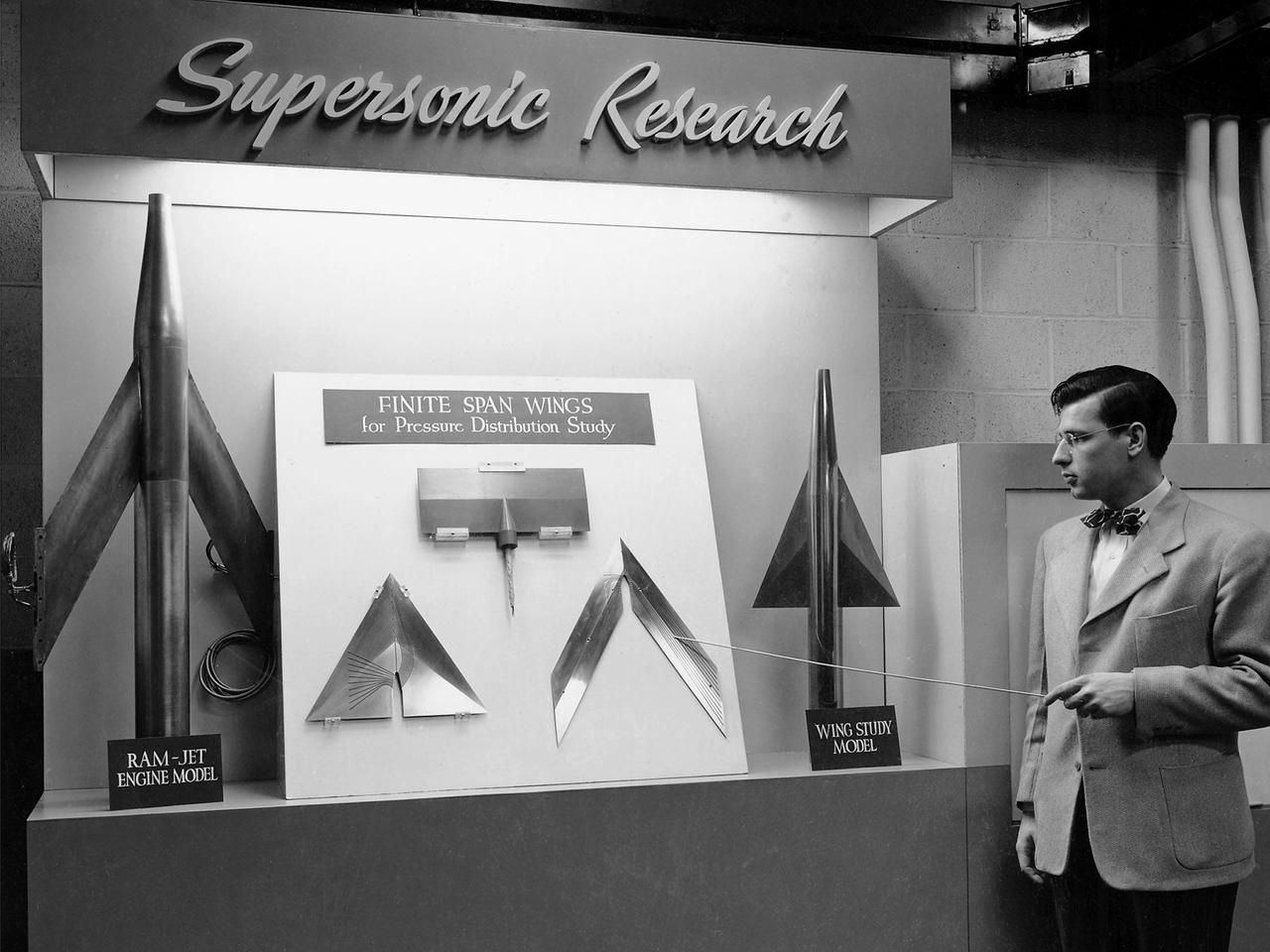
On March 22, 1946, 250 members of the Institute of Aeronautical Science toured the NACA’s Aircraft Engine Research Laboratory. NACA Chairman Jerome Hunsaker and Secretary John Victory were on hand to brief the attendees in the Administration Building before the visited the lab’s test facilities. At each of the twelve stops, researchers provided brief presentations on their work. Topics included axial flow combustors, materials for turbine blades, engine cooling, icing prevention, and supersonic flight. The laboratory reorganized itself in October 1945 as World War II came to an end to address newly emerging technologies such as the jet engine, rockets, and high-speed flight. While design work began on what would eventually become the 8- by 6-Foot Supersonic Wind Tunnel, NACA Lewis quickly built several small supersonic tunnels. These small facilities utilized the Altitude Wind Tunnel’s massive air handling equipment to generate high-speed airflow. The display seen in this photograph was set up in the building that housed the first of these wind tunnels. Eventually the building would contain three small supersonic tunnels, referred to as the “stack tunnels” because of the vertical alignment. The two other tunnels were added to this structure in 1949 and 1951. The small tunnels were used until the early 1960s to study the aerodynamic characteristics of supersonic inlets and exits.
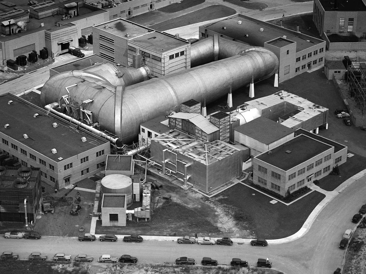
This aerial photograph shows the entire original wind tunnel complex at the National Advisory Committee for Aeronautics (NACA) Aircraft Engine Research Laboratory. The large Altitude Wind Tunnel (AWT) at the center of the photograph dominates the area. The Icing Research Tunnel to the right was incorporated into the lab’s design to take advantage of the AWT’s powerful infrastructure. The laboratory’s first supersonic wind tunnel was added to this complex just prior to this September 1945 photograph. The AWT was the nation’s only wind tunnel capable of studying full-scale engines in simulated flight conditions. The AWT’s test section and control room were within the two-story building near the top of the photograph. The exhauster equipment used to thin the airflow and the drive motor for the fan were in the building to the right of the tunnel. The unique refrigeration equipment was housed in the structure to the left of the tunnel. The Icing Research Tunnel was an atmospheric tunnel that used the AWT’s refrigeration equipment to simulate freezing rain inside its test section. A spray bar system inside the tunnel was originally used to create the droplets. The 18- by 18-inch supersonic wind tunnel was built in the summer of 1945 to take advantage of the AWT’s powerful exhaust system. It was the lab’s first supersonic tunnel and could reach Mach 1.91. Eventually the building would house three small supersonic tunnels, referred to as the “stack tunnels” because of the vertical alignment. The two other tunnels were added to this structure in 1949 and 1951.
One of the two altitude simulating-test chambers in Engine Research Building at the National Advisory Committee for Aeronautics (NACA) Lewis Flight Propulsion Laboratory. The two chambers were collectively referred to as the Four Burner Area. NACA Lewis’ Altitude Wind Tunnel was the nation’s first major facility used for testing full-scale engines in conditions that realistically simulated actual flight. The wind tunnel was such a success in the mid-1940s that there was a backlog of engines waiting to be tested. The Four Burner chambers were quickly built in 1946 and 1947 to ease the Altitude Wind Tunnel’s congested schedule. The Four Burner Area was located in the southwest wing of the massive Engine Research Building, across the road from the Altitude Wind Tunnel. The two chambers were 10 feet in diameter and 60 feet long. The refrigeration equipment produced the temperatures and the exhauster equipment created the low pressures present at altitudes up to 60,000 feet. In 1947 the Rolls Royce Nene was the first engine tested in the new facility. The mechanic in this photograph is installing a General Electric J-35 engine. Over the next ten years, a variety of studies were conducted using the General Electric J-47 and Wright Aeronautical J-65 turbojets. The two test cells were occasionally used for rocket engines between 1957 and 1959, but other facilities were better suited to the rocket engine testing. The Four Burner Area was shutdown in 1959. After years of inactivity, the facility was removed from the Engine Research Building in late 1973 in order to create the High Temperature and Pressure Combustor Test Facility.
Construction of the Propulsion Systems Laboratory No. 1 and 2 at the National Advisory Committee for Aeronautics (NACA) Lewis Flight Propulsion Laboratory. When it began operation in late 1952, the Propulsion Systems Laboratory was the NACA’s most powerful facility for testing full-scale engines at simulated flight altitudes. The facility contained two altitude simulating test chambers which were a technological combination of the static sea-level test stands and the complex Altitude Wind Tunnel, which recreated actual flight conditions on a larger scale. NACA Lewis began designing the new facility in 1947 as part of a comprehensive plan to improve the altitude testing capabilities across the lab. The exhaust, refrigeration, and combustion air systems from all the major test facilities were linked. In this way, different facilities could be used to complement the capabilities of one another. Propulsion Systems Laboratory construction began in late summer 1949 with the installation of an overhead exhaust pipe connecting the facility to the Altitude Wind Tunnel and Engine Research Building. The large test section pieces arriving in early 1951, when this photograph was taken. The two primary coolers for the altitude exhaust are in place within the framework near the center of the photograph.
National Advisory Committee for Aeronautics (NACA) design engineers added the Icing Research Tunnel to the new Aircraft Engine Research Laboratory’s original layout to take advantage of the massive refrigeration system being constructed for the Altitude Wind Tunnel. The Icing Research Tunnel was built to study the formation of ice on aircraft surfaces and methods of preventing or eradicating that ice. Ice buildup adds extra weight, effects aerodynamics, and sometimes blocks airflow through engines. The Icing Research Tunnel is a closed-loop atmospheric wind tunnel with a 6- by 9-foot test section. The tunnel can produce speeds up to 300 miles per hour and temperatures from about 30 to –45⁰ F. Initially the tunnel used a spray bar system to introduce moisture into the airstream. NACA engineers struggled for nearly 10 years to perfect the spray system. The Icing Research Tunnel began testing in June of 1944. Initial testing, seen in this photograph, studied ice accumulation on propellers of a military aircraft. NACA reserach also produced a protected air scoop for the C–46 transport aircraft. A large number of C–46 aircraft were lost due to icing while flying supply runs over the Himalayas during World War II.
A Bell P-39 Airacobra in the NACA Aircraft Engine Research Laboratory’s Icing Research Tunnel for a propeller deicing study. The tunnel, which began operation in June 1944, was built to study the formation of ice on aircraft surfaces and methods of preventing or eradicating that ice. Ice buildup adds extra weight to aircraft, effects aerodynamics, and sometimes blocks airflow through engines. NACA design engineers added the Icing Research Tunnel to the new AERL’s original layout to take advantage of the massive refrigeration system being constructed for the Altitude Wind Tunnel. The Icing Research Tunnel is a closed-loop atmospheric wind tunnel with a 6- by 9-foot test section. The tunnel can produce speeds up to 300 miles per hour and temperatures from about 30 to -45⁰ F. During World War II AERL researchers analyzed different ice protection systems for propeller, engine inlets, antennae, and wings in the icing tunnel. The P-39 was a vital low-altitude pursuit aircraft of the US during the war. NACA investigators investigated several methods of preventing ice buildup on the P-39’s propeller, including the use of internal and external electrical heaters, alcohol, and hot gases. They found that continual heating of the blades expended more energy than the aircraft could supply, so studies focused on intermittent heating. The results of the wind tunnel investigations were then compared to actual flight tests on aircraft.
A Bell P-39 Airacobra in the NACA Aircraft Engine Research Laboratory’s Icing Research Tunnel for a propeller deicing study. The tunnel, which began operation in June 1944, was built to study the formation of ice on aircraft surfaces and methods of preventing or eradicating that ice. Ice buildup adds extra weight to aircraft, effects aerodynamics, and sometimes blocks airflow through engines. NACA design engineers added the Icing Research Tunnel to the new AERL’s original layout to take advantage of the massive refrigeration system being constructed for the Altitude Wind Tunnel. The Icing Research Tunnel is a closed-loop atmospheric wind tunnel with a 6- by 9-foot test section. The tunnel can produce speeds up to 300 miles per hour and temperatures from about 30 to –45⁰ F. During World War II AERL researchers analyzed different ice protection systems for propeller, engine inlets, antennae, and wings in the icing tunnel. The P-39 was a vital low-altitude pursuit aircraft of the US during the war. NACA investigators investigated several methods of preventing ice buildup on the P-39’s propeller, including the use of internal and external electrical heaters, alcohol, and hot gases. They found that continual heating of the blades expended more energy than the aircraft could supply, so studies focused on intermittent heating. The results of the wind tunnel investigations were then compared to actual flight tests on aircraft.
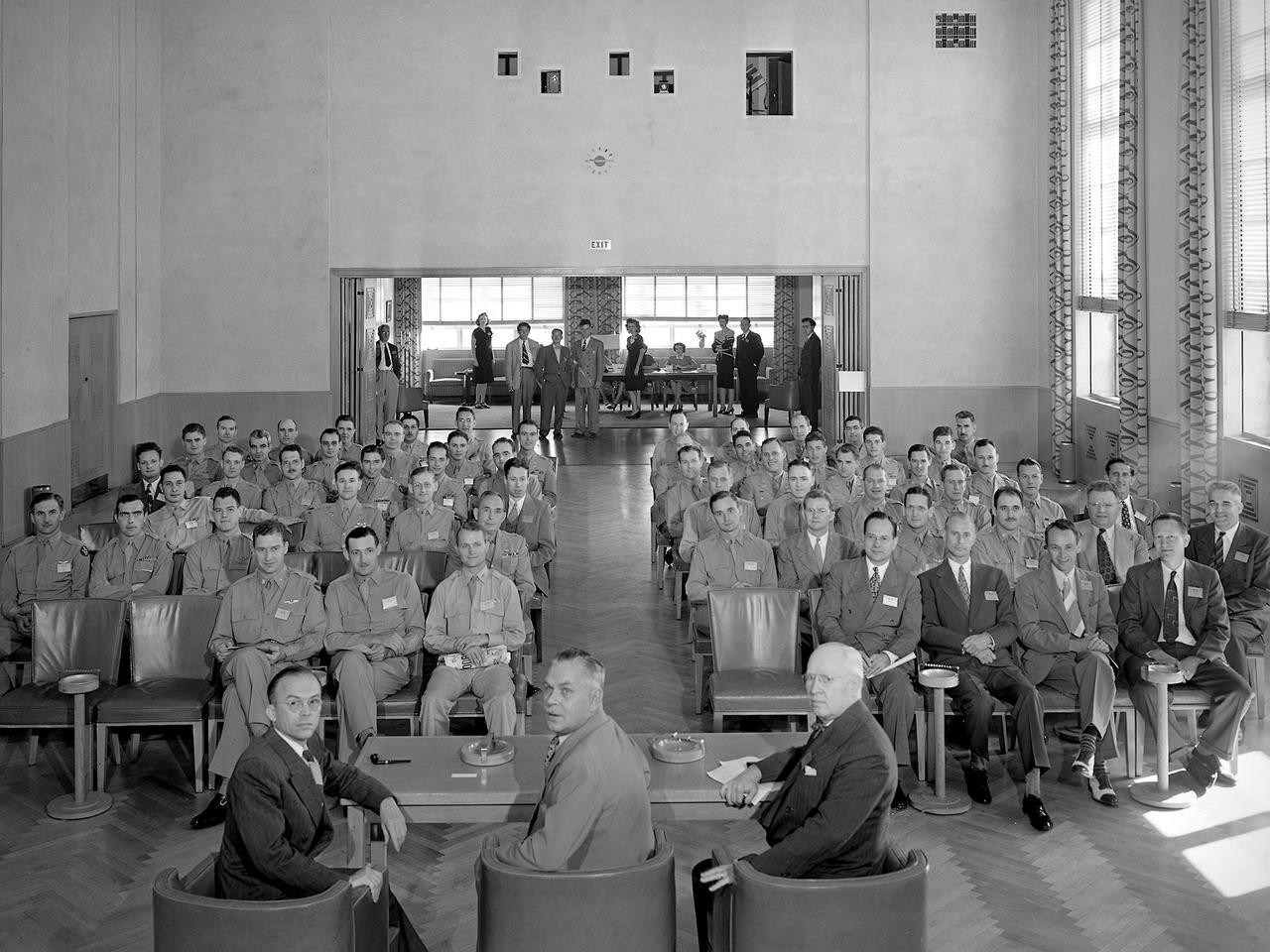
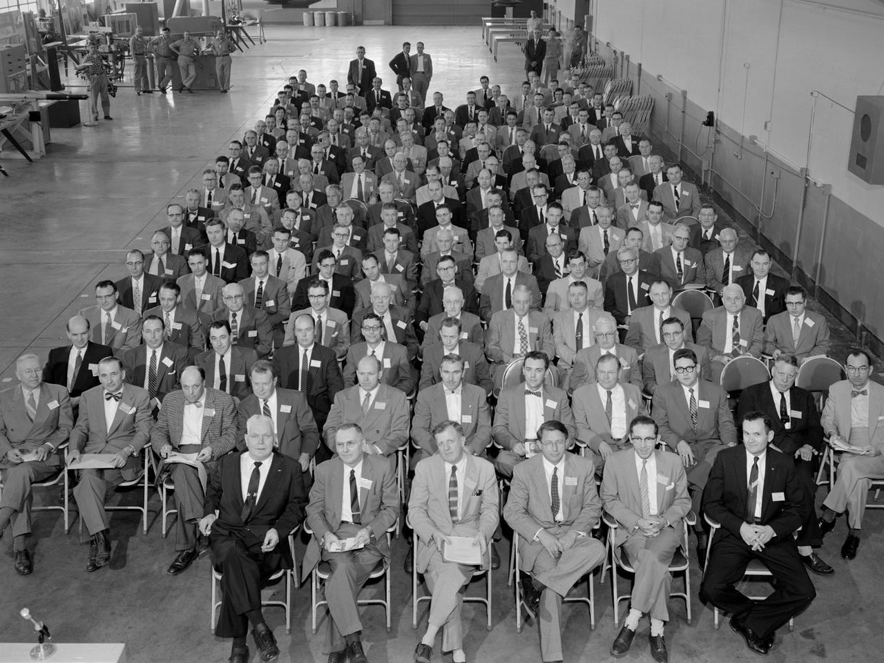
A group of 60 Army Air Forces officers visited the National Advisory Committee for Aeronautics (NACA) Aircraft Engine Research Laboratory on August 27, 1945. The laboratory enacted strict security regulations throughout World War II. During the final months of the war, however, the NACA began opening its doors to groups of writers, servicemen, and aviation industry leaders. These events were the first exposure of the new engine laboratory to the outside world. Grandstands were built alongside the Altitude Wind Tunnel specifically for group photographs. George Lewis, Raymond Sharp, and Addison Rothrock (right to left) addressed this group of officers in the Administration Building auditorium. Lewis was the NACA’s Director of Aeronautical Research, Sharp was the lab’s manager, and Rothrock was the lab’s chief of research. Abe Silverstein, Jesse Hall and others watch from the rear of the room. The group toured several facilities after the talks, including the Altitude Wind Tunnel and a new small supersonic wind tunnel. The visit concluded with a NACA versus Army baseball game and cookout.
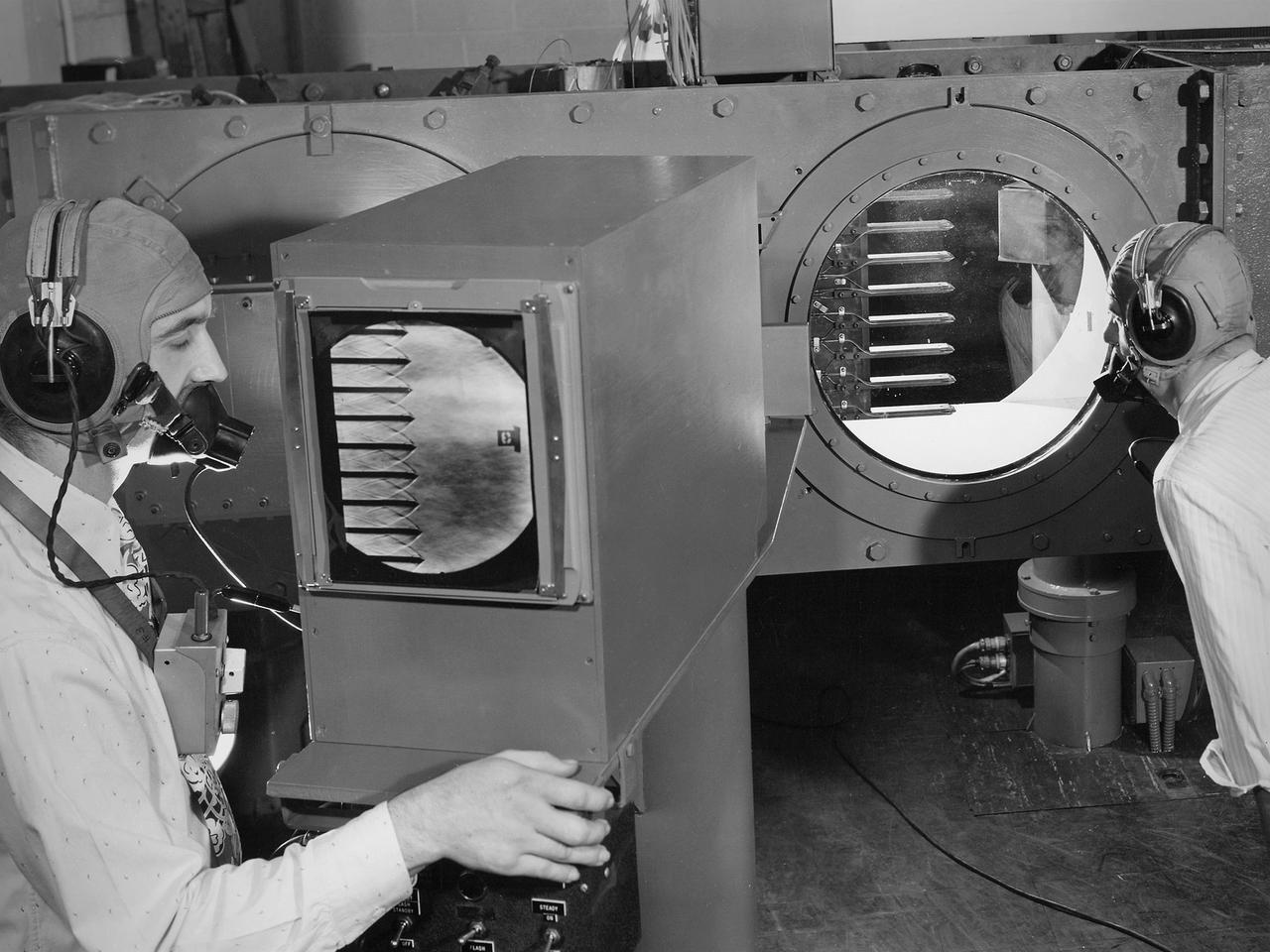
Engineers calibrate one of three small supersonic wind tunnels that were collectively referred to as the “Stack Tunnels” at the National Advisory Committee for Aeronautics (NACA) Lewis Flight Propulsion Laboratory. In late 1945 NACA Lewis reorganized its staff and began constructing a new wave of facilities to address high-speed flight and the turbojet and rocket technologies that emerged during World War II. While design work began on what would eventually become the 8- by 6-Foot Supersonic Wind Tunnel, NACA Lewis quickly built several small supersonic tunnels. These small facilities utilized the Altitude Wind Tunnel’s massive air handling equipment. Three of the small tunnels were built vertically on top of each other and thus were known as the Stack Tunnels. The first of the Stack Tunnels was an 18- by 18-inch tunnel that began operating in August 1945 at speeds up to Mach 1.91. The second tunnel, whose 24- by 24-inch test section is shown here, was added in 1949. It could generate air flows up to Mach 3.96. A third tunnel with an 18- by 18-inch test section began operating in 1951 with speeds up to Mach 3.05. The small tunnels were used until the early 1960s to study the aerodynamic characteristics of supersonic inlets and exits. The technician to the left in this photograph is operating a Schlieren camera to view the air flow dynamics inside the 24- by 24-inch test section. The technician on the right is viewing the pronged test article through the circular window. They are calibrating the tunnel and its equipment to prepare for the initial test runs.

S-65 Meteor Impact Model set up in the former Altitude Wind Tunnel at the National Aeronautics and Space Administration (NASA) Lewis Research Center just days after the September 12, 1962 rededication of the facility as the Space Power Chamber. Although larger test chambers would later be constructed, the rapid conversion of the wind tunnel into two space tanks allowed the facility to play a vital role in the early years of the space program. The eastern section of the tunnel, seen here became a vacuum chamber capable of simulating 100 miles altitude. This space tank was envisioned for the study of small satellites like this one. The transfer of the Centaur Program to Lewis one month late, however, permanently changed this mission. NASA was undertaking an in depth study at the time on the effect of micrometeoroids on satellites. Large space radiators were particularly vulnerable to damage from the small particles of space debris. In order to determine the hazard from meteoroids researchers had to define the flux rate relative to the mass and the velocity distribution because the greater the mass or the velocity of a meteoroid the greater the damage.
An Atlas/Centaur mass model undergoes a separation test inside the Space Power Chambers at NASA Lewis Research Center. Lewis was in the midst of an extensive effort to prepare the Centaur second-stage rocket for its missions to send the Surveyor spacecraft to the moon as a precursor to the Apollo missions. As part of these preparations, Lewis management decided to convert its Altitude Wind Tunnel into two large test chambers—the Space Power Chambers. The conversion included the removal of the tunnel’s internal components and the insertion of bulkheads to seal off the new chambers within the tunnel. One chamber could simulate conditions found at 100 miles altitude, while this larger chamber simulated the upper atmosphere. In this test series, researchers wanted to verify that the vehicle’s retrorockets would properly separate the Centaur from the Atlas. The model was suspended horizontally on a trolley system inside chamber. A net was hung at one end to catch the jettisoned Atlas model. The chamber atmosphere was reduced to a pressure altitude of 100,000 feet, and high-speed cameras were synchronized to the ignition of the retrorockets. The simulated Centaur is seen here jettisoning from the Atlas out of view to the right. The study resulted in a new jettison method that would significantly reduce the separation time and thus minimize the danger of collision between the two stages during separation.
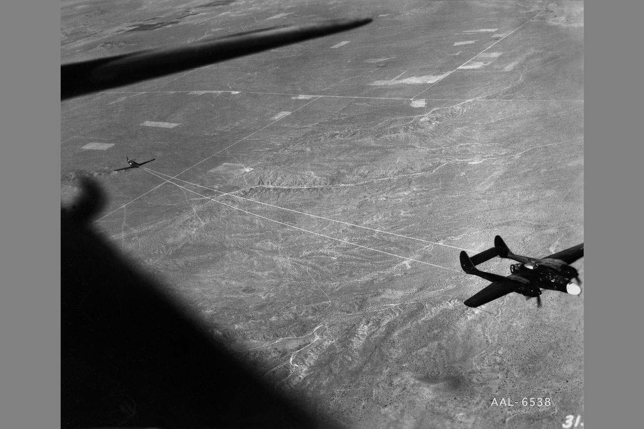
NACA photographer Northrop P-61A Black Widow towing P-51B to release altitude of 28,000 ft over Muroc Dry Lake, California for in flight validating of wind tunnel measurements of drag. After the pilot released the tow cable, drag measurementrs were obtained at various airspeeds in a 20-minute unpowered flight. Note: Used in publication in Flight Research at Ames; 57 Years of Development and Validation of Aeronautical Technology NASA SP-1998-3300 Fig. 17
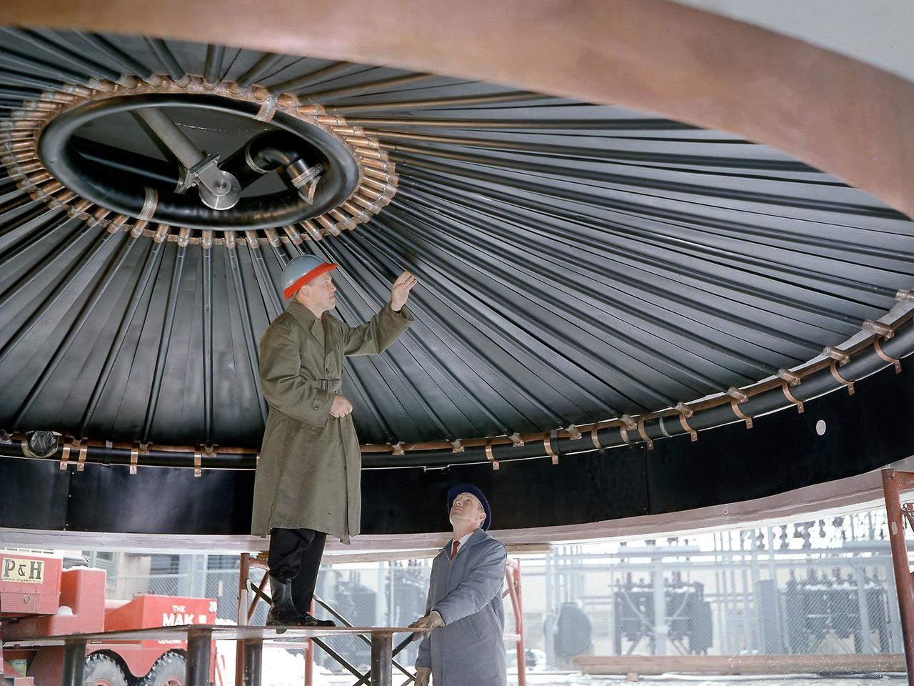
A National Advisory Committee for Aeronautics (NACA) researcher measures the ice thickness on a landing antenna model in the Icing Research Tunnel at the Aircraft Engine Research Laboratory. NACA design engineers added the Icing Research Tunnel to the original layout of the new Aircraft Engine Research Laboratory to take advantage of the massive refrigeration system being built for the Altitude Wind Tunnel. The Icing Research Tunnel was built to study the formation of ice on aircraft surfaces and methods of preventing or eradicating that ice. Ice buildup adds extra weight, effects aerodynamics, and sometimes blocks air flow through engines. The Icing Research Tunnel is a closed-loop atmospheric wind tunnel with a 6- by 9-foot test section. Carrier Corporation refrigeration equipment reduced the internal air temperature to -45 degrees F and a spray bar system injected water droplets into the air stream. The 24-foot diameter drive fan, seen in this photograph, created air flows velocities up to 400 miles per hour. The Icing Research Tunnel began testing in June of 1944. Early testing, seen in this photograph, studied ice accumulation on propellers and antenna of a military aircraft. The Icing Research Tunnel’s designers, however, struggled to develop a realistic spray system since they did not have access to data on the size of naturally occurring water droplets. The system would have to generate small droplets, distribute them uniformly throughout the airstream, and resist freezing and blockage. For five years a variety of different designs were painstakingly developed and tested before the system was perfected.
Researchers check the setup of a multi-nozzle base flow model in the 10- by 10-Foot Supersonic Wind Tunnel at the National Aeronautics and Space Administration (NASA) Lewis Research Center. NASA researchers were struggling to understand the complex flow phenomena resulting from the use of multiple rocket engines. Robert Wasko and Theodore Cover of the Advanced Development and Evaluation Division’s analysis and operations sections conducted a set of tests in the 10- by 10 tunnel to further understand the flow issues. The Lewis researchers studied four and five-nozzle configurations in the 10- by 10 at simulated altitudes from 60,000 to 200,000 feet. The nozzles were gimbaled during some of the test runs to simulate steering. The flow field for the four-nozzle clusters was surveyed in the center and the lateral areas between the nozzles, whereas the five-nozzle cluster was surveyed in the lateral area only.
This 22.5-foot-diameter domed lid was added to the Space Power Chambers to allow the vertical installation of a Centaur second-stage rocket into the vacuum tank at the National Aeronautics and Space Administration (NASA) Lewis Research Center. The lid could be removed using a crane so that the Centaur could be lowered into the chamber. After a year of additional construction, the new dome and extension were completed in September 1963. The feature became the facility’s distinctive attribute. The modifications to the facility began two years earlier, however. In 1961, NASA Lewis management decided to convert the Altitude Wind Tunnel into two large test chambers and later renamed it the Space Power Chambers. The conversion included the removal of the tunnel’s internal components and the insertion of bulkheads to seal off the new chambers within the tunnel. The 100-foot-long vacuum tank was created in the east leg of the tunnel, which was 31 feet in diameter at one end and 27 feet in diameter at the other. With the transfer of the Centaur second-stage rocket program to NASA Lewis in October 1962, the newly completed Space Power Chambers facility had to be modified to accommodate the space vehicle. The goal of the test engineers was to subject the Centaur to long durations in conditions that would replicate those encountered during its missions in space. The facility was used for a variety of tests on the Centaur second-stage rocket until the early 1970s.
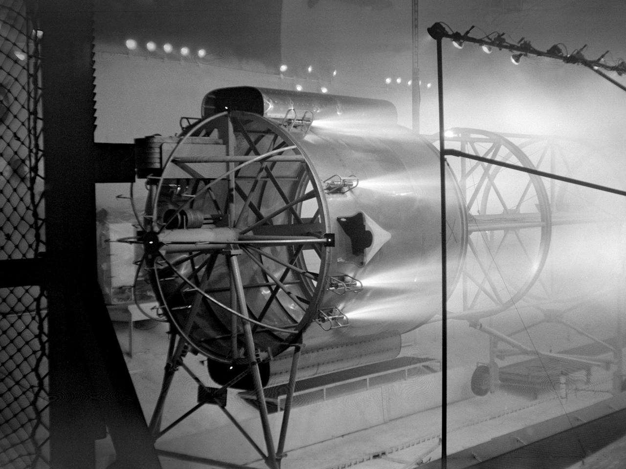
The NACA’s Lewis Flight Propulsion Laboratory used a Boeing B‒29 Superfortress as a testbed for ramjet investigations in the late 1940s. Lewis researchers conducted a wide variety of studies on ramjets to determine basic the operational data necessary to design missiles. Extensive wind tunnel and test stand studies were augmented by actual flight tests. Lewis engineers modified this B‒29 so that the ramjet could be stored in the bomb bay. Once the aircraft reached the desired altitude and speed, a mechanical arm suspended the ramjet 52 inches below the bomb bay. The ramjet’s angle-of-attack could be independently adjusted, and a periscope permitted a view of the test article from inside the aircraft. Researchers took measurements in free-stream conditions at speeds up to Mach 0.51 and at altitudes ranging from 5,000 to 30,000 feet. They then shut the ramjet down and retracted it into the aircraft. The researchers first determined that 14,000 feet was the maximum altitude at which the engine could be ignited by spark. They used flares to start the engine at altitudes up to 30,000 feet. They were able to determine maximum combustion efficiencies, response time to changes in fuel flow, and minimum fuel-air ratios. Overall the ramjet operated well at all speeds and altitudes.
Setup of a Surveyor/Atlas/Centaur shroud in the Space Power Chambers for a leak test at the National Aeronautics and Space Administration (NASA) Lewis Research Center. Centaur was a 15,000-pound thrust second-stage rocket designed for the military in 1957 and 1958 by General Dynamics. It was the first major rocket to use the liquid hydrogen technology developed by Lewis in the 1950s. The Centaur Program suffered numerous problems before being transferred to Lewis in 1962. Several test facilities at Lewis’ main campus and Plum Brook Station were built or modified specifically for Centaur, including the Space Power Chambers. In 1961, NASA Lewis management decided to convert its Altitude Wind Tunnel into two large test chambers and later renamed it the Space Power Chambers. The conversion, which took over 2 years, included the removal of the tunnel’s internal components and insertion of bulkheads to seal off the new chambers. The larger chamber, seen here, could simulate altitudes of 100,000 feet. It was used for Centaur shroud separation and propellant management studies until the early 1970s. The leak test in this photograph was likely an attempt to verify that the shroud’s honeycomb shell did not seep any of its internal air when the chamber was evacuated to pressures similar to those found in the upper atmosphere.
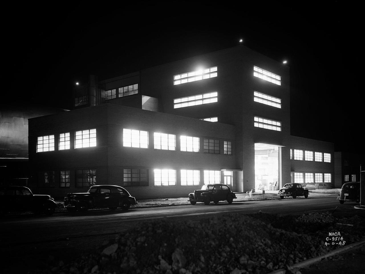
The National Advisory Committee for Aeronautics (NACA) Lewis Flight Propulsion Laboratory in Cleveland, Ohio as seen from the west in May 1946. The Cleveland Municipal Airport is located directly behind. The laboratory was built in the early 1940s to resolve problems associated with aircraft engines. The initial campus contained seven principal buildings: the Engine Research Building, hangar, Fuels and Lubricants Building, Administration Building, Engine Propeller Research Building, Altitude Wind Tunnel, and Icing Research Tunnel. These facilities and their associated support structures were located within an area occupying approximately one-third of the NACA’s property. After World War II ended, the NACA began adding new facilities to address different problems associated with the newer, more powerful engines and high speed flight. Between 1946 and 1955, four new world-class test facilities were built: the 8- by 6-Foot Supersonic Wind Tunnel, the Propulsion Systems Laboratory, the Rocket Engine Test Facility, and the 10- by 10-Foot Supersonic Wind Tunnel. These large facilities occupied the remainder of the NACA’s semicircular property. The Lewis laboratory expanded again in the late 1950s and early 1960s as the space program commenced. Lewis purchased additional land in areas adjacent to the original laboratory and acquired a large 9000-acre site located 60 miles to the west in Sandusky, Ohio. The new site became known as Plum Brook Station.
A female computer at the National Advisory Committee for Aeronautics (NACA) Lewis Flight Propulsion Laboratory with a slide rule and Friden adding machine to make computations. The computer staff was introduced during World War II to relieve short-handed research engineers of some of the tedious computational work. The Computing Section was staffed by “computers,” young female employees, who often worked overnight when most of the tests were run. The computers obtained test data from the manometers and other instruments, made the initial computations, and plotted the data graphically. Researchers then analyzed the data and summarized the findings in a report or made modifications and ran the test again. There were over 400 female employees at the laboratory in 1944, including 100 computers. The use of computers was originally planned only for the duration of the war. The system was so successful that it was extended into the 1960s. The computers and analysts were located in the Altitude Wind Tunnel Shop and Office Building office wing during the 1940s and transferred to the new 8- by 6-Foot Supersonic Wind Tunnel in 1948.
A Lockheed F-94B Starfire being equipped with an audio recording machine and sensors at the National Advisory Committee for Aeronautics (NACA) Lewis Flight Propulsion Laboratory. The NACA was investigating the acoustic effects caused by the engine’s nozzle and the air flowing along the fuselage. Airline manufacturers would soon be introducing jet engines on their passenger aircraft, and there was concern regarding the noise levels for both the passengers and public on the ground. NACA Lewis conducted a variety of noise reduction studies in its wind tunnels, laboratories, and on a F2H-2B Banshee aircraft. The F2H-2B Banshee’s initial test flights in 1955 and 1956 measured the noise emanating directly from airflow over the aircraft’s surfaces, particularly the wings. This problem was particularly pronounced at high subsonic speeds. The researchers found the majority of the noise occurred in the low and middle octaves. These investigations were enhanced with a series of flights using the F-94B Starfire. The missions measured wall-pressure, turbulence fluctuations, and mean velocity profiles. Mach 0.3 to 0.8 flights were flown at altitudes of 10,000, 20,000, and 30,000 feet with microphones mounted near the forward fuselage and on a wing. The results substantiated the wind tunnel findings. This photograph shows the tape recorder being installed in the F-94B’s nose.
Attendees listen during the May 22, 1956 Inspection of the new 10- by 10-Foot Supersonic Wind Tunnel at the National Advisory Committee for Aeronautics (NACA) Lewis Flight Propulsion Laboratory. The facility, known at the time as the Lewis Unitary Plan Tunnel, was in its initial stages of operation. The $33 million 10- by 10 was the most powerful wind tunnel in the nation. Over 150 guests from industry, other NACA laboratories, and the media attended the event. The speakers, from left to right in the front row, addressed the crowd before the tour. Lewis Director Raymond Sharp began the event by welcoming the visitors to the laboratory. NACA Director Hugh Dryden discussed Congress’ Unitary Plan Act and its effect on the creation of the facility. Lewis Associate Director Abe Silverstein discussed the need for research tools and the 10- by 10’s place among the NACA’s other research facilities. Lewis Assistant Director Eugene Wasielewski described the detailed design work that went into the facility. Carl Schueller, Chief of the 10- by 10, described the tunnel’s components and how the facility operated. Robert Godman led the tour afterwards. The 10- by 10 can test engines up to five feet in diameter at supersonic speeds and simulated altitudes of 30 miles. Its main purpose is to investigate problems relating to engine inlet and outlet geometry, engine matching and interference effects, and overall drag. The tunnel’s 250,000-horsepower electric motor drive, the most powerful of its kind in the world, creates air speeds between Mach 2.0 and 3.5.
Engineers at the National Aeronautics and Space Administration (NASA) Lewis Research Center inspect the nitrogen baffle in the interior of the 22.5-foot diameter dome at the Space Power Chambers. In 1961 NASA Lewis management decided to convert the Altitude Wind Tunnel into two large test chambers and renamed the facility the Space Power Chambers. The conversion, which took over two years, included removing the tunnel’s drive fan, exhaust scoop, and turning vanes from the east end and inserting bulkheads to seal off the new chambers within the tunnel. The eastern section of the tunnel became a vacuum chamber capable of simulating 100 miles altitude. In 1962 NASA management decided to use the new vacuum chamber exclusively to study the second-stage rocket. This required significant modifications to the new tank and extensive test equipment to create a space environment. The Lewis test engineers sought to subject the Centaur to long durations in conditions that would replicate those encountered during its missions in space. The chamber was already capable of creating the vacuum of space, but the test engineers also wanted to simulate the cryogenic temperatures and solar radiation found in space. Six panels of 500-watt tungsten-iodine lamps were arranged around the Centaur to simulate the effect of the Sun’s heat. A large copper cold wall with its interior coated with heat-absorbing black paint was created specifically for these tests and assembled around the Centaur. The 42-foot-high wall had vertical ribs filled with liquid nitrogen which produced the low temperatures.

One of the two primary coolers at the Propulsion Systems Laboratory at the National Advisory Committee for Aeronautics (NACA) Lewis Flight Propulsion Laboratory. Engines could be run in simulated altitude conditions inside the facility’s two 14-foot-diameter and 24-foot-long test chambers. The Propulsion Systems Laboratory was the nation’s only facility that could run large full-size engine systems in controlled altitude conditions. At the time of this photograph, construction of the facility had recently been completed. Although not a wind tunnel, the Propulsion Systems Laboratory generated high-speed airflow through the interior of the engine. The air flow was pushed through the system by large compressors, adjusted by heating or refrigerating equipment, and de-moisturized by air dryers. The exhaust system served two roles: reducing the density of the air in the test chambers to simulate high altitudes and removing hot gases exhausted by the engines being tested. It was necessary to reduce the temperature of the extremely hot engine exhaust before the air reached the exhauster equipment. As the air flow exited through exhaust section of the test chamber, it entered into the giant primary cooler seen in this photograph. Narrow fins or vanes inside the cooler were filled with water. As the air flow passed between the vanes, its heat was transferred to the cooling water. The cooling water was cycled out of the system, carrying with it much of the exhaust heat.
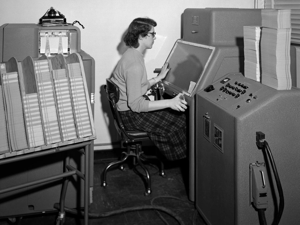
A staff member from the Computing Section at the National Advisory Committee for Aeronautics (NACA) Lewis Flight Propulsion Laboratory operates an International Business Machines (IBM) telereader at the 8- by 6-Foot Supersonic Wind Tunnel. The telereader was used to measure recorded data from motion picture film or oscillographs. The machine could perform 50 measurements per minute. The component to her right is a telerecordex that was used convert the telereader measurements into decimal form and record the data on computer punch cards. During test runs in the 8- by 6-foot tunnel, or the other large test facilities, pressure sensors on the test article were connected to mercury-filled manometer tubes located below the test section. The mercury would rise or fall in relation to the pressure fluctuations in the test section. Initially, female staff members, known as “computers,” transcribed all the measurements by hand. The process became automated with the introduction of the telereader and other data reduction equipment in the early 1950s. The Computer Section staff members were still needed to operate the machines. The Computing Section was introduced during World War II to relieve short-handed research engineers of some of the tedious work. The computers made the initial computations and plotted the data graphically. The researcher then analyzed the data and either summarized the findings in a report or made modifications or ran the test again. The computers and analysts were located in the Altitude Wind Tunnel Shop and Office Building office wing during the 1940s. They were transferred to the new facility when the 8- by 6-Foot tunnel began operations in 1948.
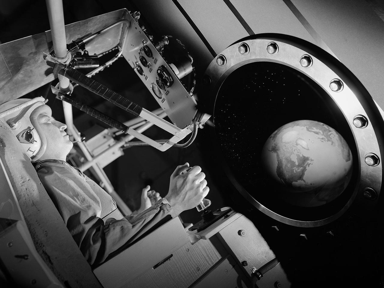
This composite image includes a photograph of pilot Joe Algranti testing the Multi-Axis Space Test Inertia Facility (MASTIF) inside Altitude Wind Tunnel at NASA’s Lewis Research Center with other images designed to simulate the interior of a Mercury space capsule. As part of the space agency’s preparations for Project Mercury missions, the seven Mercury astronauts traveled to Cleveland in early 1960 to train on the MASTIF. Researchers used the device to familiarize the astronauts with the sensations of an out-of-control spacecraft. The MASTIF was a three-axis rig with a pilot’s chair mounted in the center. An astronaut was secured in a foam couch in the center of the rig. The rig then spun on three axes from 2 to 50 rotations per minute. The astronauts used small nitrogen gas thrusters to bring the MASTIF under control. In the fall of 1959, prior to the astronauts’ visit, Lewis researcher James Useller and Algranti perfected and calibrated the MASTIF.
The NACA’s Lewis Flight Propulsion Laboratory used a Boeing B-29 Superfortress as a testbed for ramjet investigations in the late 1940s. NACA Lewis conducted a wide variety of studies on ramjets to determine basic operational data necessary to design missiles. This information included the relationship between combustion chamber and inlet pressure and temperature, velocity of the fuel-air ratio to the ignition characteristics, and combustion efficiency. Although wind tunnel and test stand studies were important first steps in determining these factors, actual flight tests were required. Lewis engineers modified the B-29 so that the ramjet could be stored in the bomb bay. Once the aircraft reached the desired altitude and speed the ramjet was suspended 52 inches below the bomb bay. The ramjet’s angle-of-attack could be independently adjusted, and a periscope permitted a view of the test article from inside the aircraft. Measurements were taken in free-stream conditions between 5,000 and 30,000 feet. The test flights, which began in April 1947, were flown at speeds up to Mach 0.51 and altitudes of 5,000 to 30,000 feet. The researchers first determined that 14,000 feet was the maximum altitude at which the engine could be ignited by spark. Flares were used to start the engine at altitudes up to 30,000 feet. Overall the ramjet operated well at all speeds and altitudes. Significant changes in fuel flow were successful at lower altitudes, but produced combustion blowout above 20,000 feet.
Researchers at the National Aeronautics and Space Administration (NASA) Lewis Research Center conducted a series of shroud jettison tests for the second Orbiting Astronomical Observatory (OAO-2) in the Space Power Chambers during April 1968. The Orbiting Astronomical Observatory satellites were designed by Goddard Space Flight Center to study and retrieve ultraviolet data on stars and galaxies which earthbound and atmospheric telescopes could not view due to ozone absorption. The shroud jettison system was tested in the Space Power Chambers. In 1961, NASA Lewis management decided to convert its Altitude Wind Tunnel into two large test chambers and later renamed it the Space Power Chambers. The conversion, which took over two years, included removing the tunnel’s internal components and inserting bulkheads to seal off the new chambers. The larger chamber, seen here, could simulate altitudes of 100,000 feet. These chambers were used for a variety of tests on the Centaur second-stage rocket until the early 1970s. The first OAO mission in 1965 failed due to problems with the satellite. OAO-2 would be launched on an Atlas/Centaur with a modified Agena shroud. The new shroud was 18 feet longer than the normal Centaur payload shrouds. This new piece of hardware was successfully qualified during three tests at 90,000 feet altitude in the Space Power Chambers in April 1968. For the first time, x-rays were used to verify the payload clearance once the shroud was sealed. OAO-2 was launched on December 7, 1968 and proved to be an extremely successful mission.
Pilot William Swann, right cockpit, prepares the North American XF-82 Twin Mustang for flight at the National Advisory Committee for Aeronautics (NACA) Lewis Flight Propulsion Laboratory. The aircraft was one of only two prototypes built by North American in October 1945 and powered by Packard Merlin V-1650 piston engines. Over 270 of the F-82 long-distance pursuit fighters were produced during the 1940s. The Mustang’s unique two-pilot configuration allowed one pilot to rest during the long missions and thus be ready for action upon arrival. The NACA took possession of this XF-82 in October 1947. NACA Lewis used the XF-82 as a test bed for ramjet flight tests. Ramjets are continually burning tubes that use the compressed atmospheric air to produce thrust. Ramjets are extremely efficient at high speeds, but rely on some sort of booster to attain that high speed. NACA Lewis undertook an extensive ramjet program in the 1940s that included combustion studies in the Altitude Wind Tunnel, a number of flight tests, and missile drops from aircraft. The 16-inch diameter ramjet missile was fixed to the XF-82 Mustang’s wing and dropped from high altitudes off of Wallops Island. The tests determined the ramjet’s performance and operational characteristics in the transonic range.
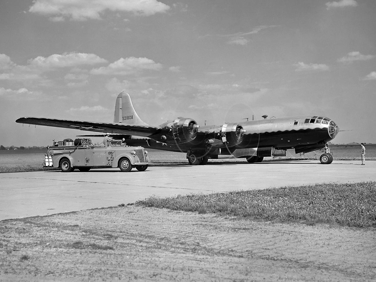
A Boeing B–29 Superfortress at the National Advisory Committee for Aeronautics (NACA) Aircraft Engine Research Laboratory in Cleveland, Ohio. The B–29 was the Army Air Forces’ deadliest weapon during the latter portion of World War II. The aircraft was significantly larger than previous bombers but could fly faster and higher. The B–29 was intended to soar above anti-aircraft fire and make pinpoint drops onto strategic targets. The bomber was forced to carry 20,000 pounds more armament than it was designed for. The extra weight pushed the B–29’s four powerful Wright R–3350 engines to their operating limits. The over-heating of the engines proved to be a dangerous problem. The military asked the NACA to tackle the issue. Full-scale engine tests on a R–3350 engine in the Prop House demonstrated that a NACA-designed impeller increased the flow rate of the fuel injection system. Altitude Wind Tunnel studies of the engine led to the reshaping of cowling inlet and outlet to improve airflow and reduce drag. Single-cylinder studies on valve failures were resolved by a slight extension of the cylinder head, and the Engine Research Building researchers combated uneven heating with a new fuel injection system. The modifications were then tried out on an actual B–29. The bomber arrived in Cleveland on June 22, 1944. The new injection impeller, ducted head baffles and instrumentation were installed on the bomber’s two left wing engines. Eleven test flights were flown over the next month with military pilots at the helm. Overall the flight tests corroborated the wind tunnel and test stand studies.
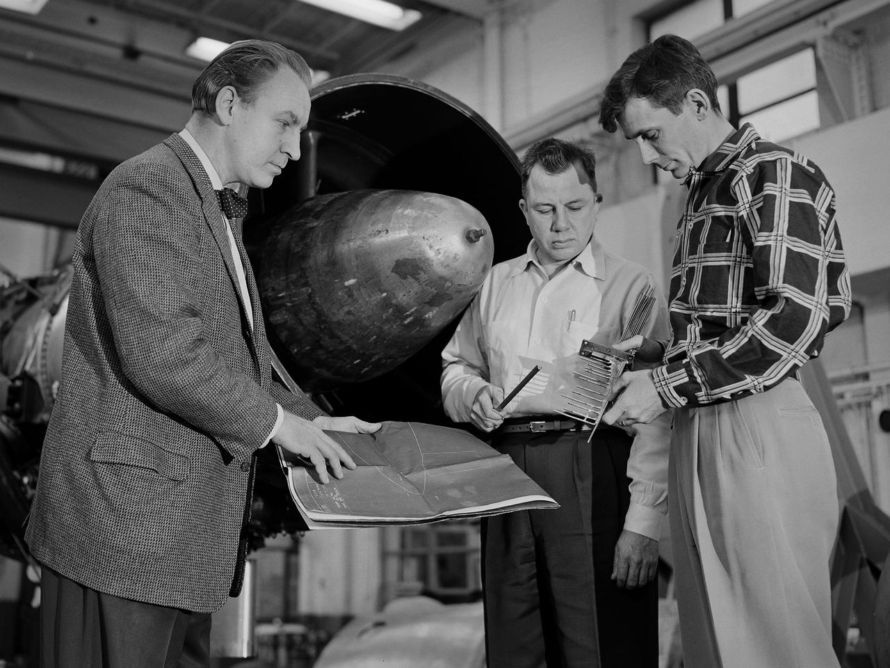
Researcher Bill Reiwaldt discusses the preparations for a test in the Altitude Wind Tunnel with technicians Jack Wagner and Dick Golladay at the National Advisory Committee for Aeronautics (NACA) Lewis Flight Propulsion Laboratory. Research engineers developed ideas for tests that were often in response to requests from the military or aircraft industry. Arrangements were made to obtain an engine for the study and to transport it to the Cleveland laboratory. The engine was brought into the facility’s shop area, where it was readied for investigation. It was common for several different engines to be worked on simultaneously in the shop. The researcher would discuss the engine and the test objectives with the Test Installation Division and the facility’s technicians. The operations team would handle the installation of the instrumentation and fitting the test into the facility’s schedule. Upon completion of the previous test, the engine was removed. The next engine was lifted by an overhead crane and transported from the shop to the test section. The engine was connected to the measurement devices and fuel and oil supply lines. Engines were tested over numerous runs under varying conditions and with variations on the configuration. The findings and test procedure were then described in research or technical memorandums and distributed to industry.
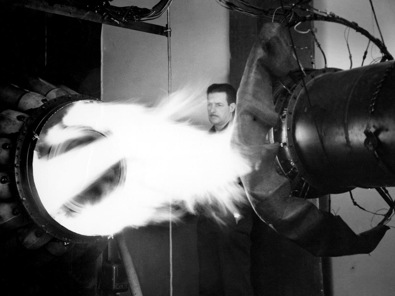
A mechanic watches the firing of a General Electric I-40 turbojet at the National Advisory Committee for Aeronautics (NACA) Lewis Flight Propulsion Laboratory. The military selected General Electric’s West Lynn facility in 1941 to secretly replicate the centrifugal turbojet engine designed by British engineer Frank Whittle. General Electric’s first attempt, the I-A, was fraught with problems. The design was improved somewhat with the subsequent I-16 engine. It was not until the engine's next reincarnation as the I-40 in 1943 that General Electric’s efforts paid off. The 4000-pound thrust I-40 was incorporated into the Lockheed Shooting Star airframe and successfully flown in June 1944. The Shooting Star became the US’s first successful jet aircraft and the first US aircraft to reach 500 miles per hour. NACA Lewis studied all of General Electric’s centrifugal turbojet models during the 1940s. In 1945 the entire Shooting Star aircraft was investigated in the Altitude Wind Tunnel. Engine compressor performance and augmentation by water injection; comparison of different fuel blends in a single combustor; and air-cooled rotors were studied. The mechanic in this photograph watches the firing of a full-scale I-40 in the Jet Propulsion Static Laboratory. The facility was quickly built in 1943 specifically in order to test the early General Electric turbojets. The I-A was secretly analyzed in the facility during the fall of 1943.

Jerrie Cobb prepares to operate the Multi-Axis Space Test Inertia Facility (MASTIF) inside the Altitude Wind Tunnel at the National Aeronautics and Space Administration (NASA) Lewis Research Center. The MASTIF was a three-axis rig with a pilot’s chair mounted in the center to train Project Mercury pilots to bring a spinning spacecraft under control. An astronaut was secured in a foam couch in the center of the rig. The rig was then spun on three axes from 2 to 50 rotations per minute. The pilots were tested on each of the three axis individually, then all three simultaneously. The two controllers in Cobb’s hands activated the small nitrogen gas thrusters that were used to bring the MASTIF under control. A makeshift spacecraft control panel was set up in front of the trainee’s face. Cobb was one of several female pilots who underwent the skill and endurance testing that paralleled that of the Project Mercury astronauts. In 1961 Jerrie Cobb was the first female to pass all three phases of the Mercury Astronaut Program. NASA rules, however, stipulated that only military test pilots could become astronauts and there were no female military test pilots. The seven Mercury astronauts had taken their turns on the MASTIF in February and March 1960.
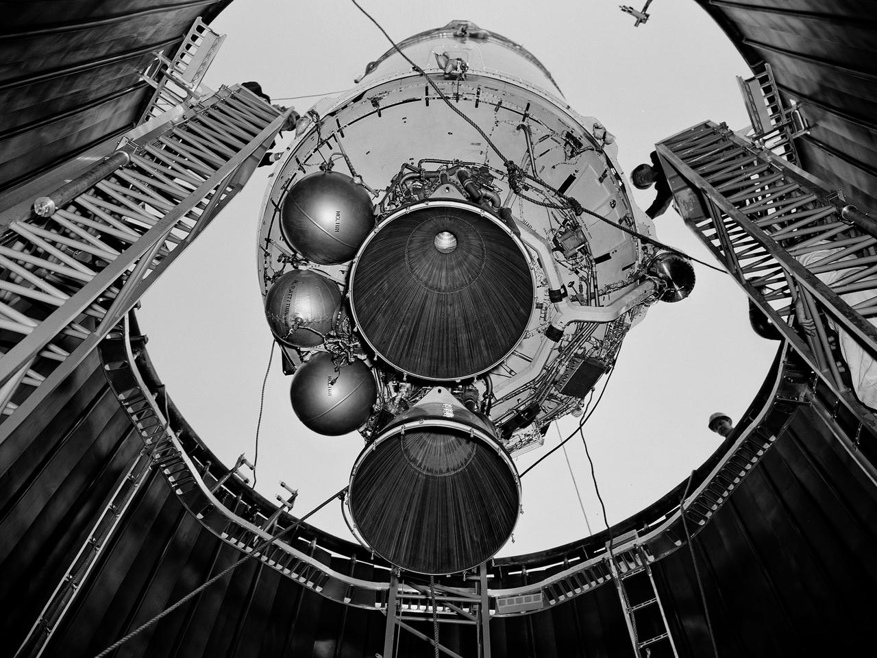
A Centaur second-stage rocket is lowered into the vacuum tank inside the Space Power Chambers at NASA’s Lewis Research Center. Centaur was to be paired with an Atlas booster to send the Surveyor spacecraft to the moon as a precursor to the Apollo landings. Lewis was assigned responsibility for the Centaur Program after the failure of its first developmental flight in May 1962. Lewis’ Altitude Wind Tunnel was converted into two large test chambers—the Space Power Chambers. The facility’s vacuum chamber, seen here, allowed the Centaur to be stood up vertically and subjected to atmospheric conditions-- pressures, temperature, and radiation--similar to those it would encounter in space. The Centaur for these tests was delivered to Cleveland in a C‒130 aircraft on September 27, 1963. The rocket was set up in the facility’s high bay where Lewis technicians and General Dynamics consultants updated its flight systems to match the upcoming Atlas-Centaur‒4 mission. Months were spent reharnessing the Centaur’s electronics, learning about the systems, and being taught how to handle flight hardware. By early spring 1964, the extensive setup of both the spacecraft and the chamber was finally completed. On March 19 the Centaur was rolled out from the shop, hoisted high into the air by a crane, and lowered into the waiting space tank. Researchers were able to verify that the Centaur’s electronics and electrical systems functioned reliably in a space environment.
A Boeing B-47 Stratojet bomber with a noise-reducing ejector on its engine at the 1957 Inspection of the National Advisory Committee for Aeronautics (NACA) Lewis Flight Propulsion Laboratory. Representatives from the military, aeronautical industry, universities, and the press were invited to the laboratory to be briefed on the NACA’s latest research efforts and tour the state- of- the- art test facilities. Over 1700 people visited the NACA Lewis in Cleveland, Ohio during October 7 - 10, 1957. By the mid-1950s, the aircraft industry was close to introducing jet airliners to the nation’s airways. The noise produced by the large jet engines, however, would pose a considerable problem for communities near airports. This problem was demonstrated at the 1957 Inspection by an NACA Lewis researcher who played longplay (LP) audio records of military jet engines for an audience. Tests showed that the source of the loudest noise was not the engine itself, but the mixing of the engine’s exhaust with the surrounding air in the atmosphere. The pressures resulting from this turbulence produced sound waves. One of Lewis’ first studies sought to design an exhaust nozzle that reduced the turbulence. A Pratt and Whitney J57 was tested in the Altitude Wind Tunnel with many of these nozzle configurations from January to May 1957. Researchers found that the various nozzle types did reduce the noise levels but also reduced the aircraft’s thrust. Afterwards, they determined that the addition of an NACA-developed ejector reduced the noise levels without diminishing thrust.
During the 1970s, the focus at Dryden shifted from high-speed and high-altitude flight to incremental improvements in technology and aircraft efficiency. One manifestation of this trend occurred in the winglet flight research carried out on a KC-135 during 1979 and 1980. Richard Whitcomb at the Langley Research Center had originated the idea of adding small vertical fins to an aircraft's wing tips. His wind tunnel tests indicated that winglets produced a forward thrust, which reduced the strength of the vortices generated by an aircraft's wing tips and resulted in a reduction of drag and an increase in aircraft range. Whitcomb, who had previously developed the area rule concept and the supercritical wing, selected the best winglet shape for flight tests on a KC-135 tanker. When the tests were completed, the data showed that the winglets provided a 7 percent improvement in range over the standard KC-135. The obvious economic advantage at a time of high fuel costs caused winglets to be adopted on business jets, airliners, and heavy military transports.

Mercury astronaut John Glenn prepares for a test in the Multi-Axis Space Test Inertia Facility (MASTIF) inside the Altitude Wind Tunnel at the National Aeronautics and Space Administration (NASA) Lewis Research Center. The MASTIF was a three-axis test rig with a pilot’s chair mounted in the center. The device was designed to train Project Mercury pilots to bring a spinning spacecraft under control. An astronaut was secured in a foam couch in the center of the rig. The rig was then spun on three axes from 2 to 50 rotations per minute. Small nitrogen gas thrusters were used by the astronauts to bring the MASTIF under control. In February and March 1960, the seven Project Mercury astronauts traveled to Cleveland to train on the MASTIF. Warren North and a team of air force physicians were on hand to monitor their health. After being briefed by Lewis pilot Joe Algranti and researcher James Useller, the rider would climb into the rig and be secured in the chair, as seen in this photograph. A Lewis engineer would then slowly set the MASTIF in motion. It was the astronaut’s job to bring it under control. Each individual was required to accumulate 4.5 to 5 hours of MASTIF time. Glenn became the first American to orbit the earth on February 20, 1962 in the Friendship 7 Mercury capsule. In March 1999, the Lewis Research Center was renamed the John H. Glenn Research Center at Lewis Field.
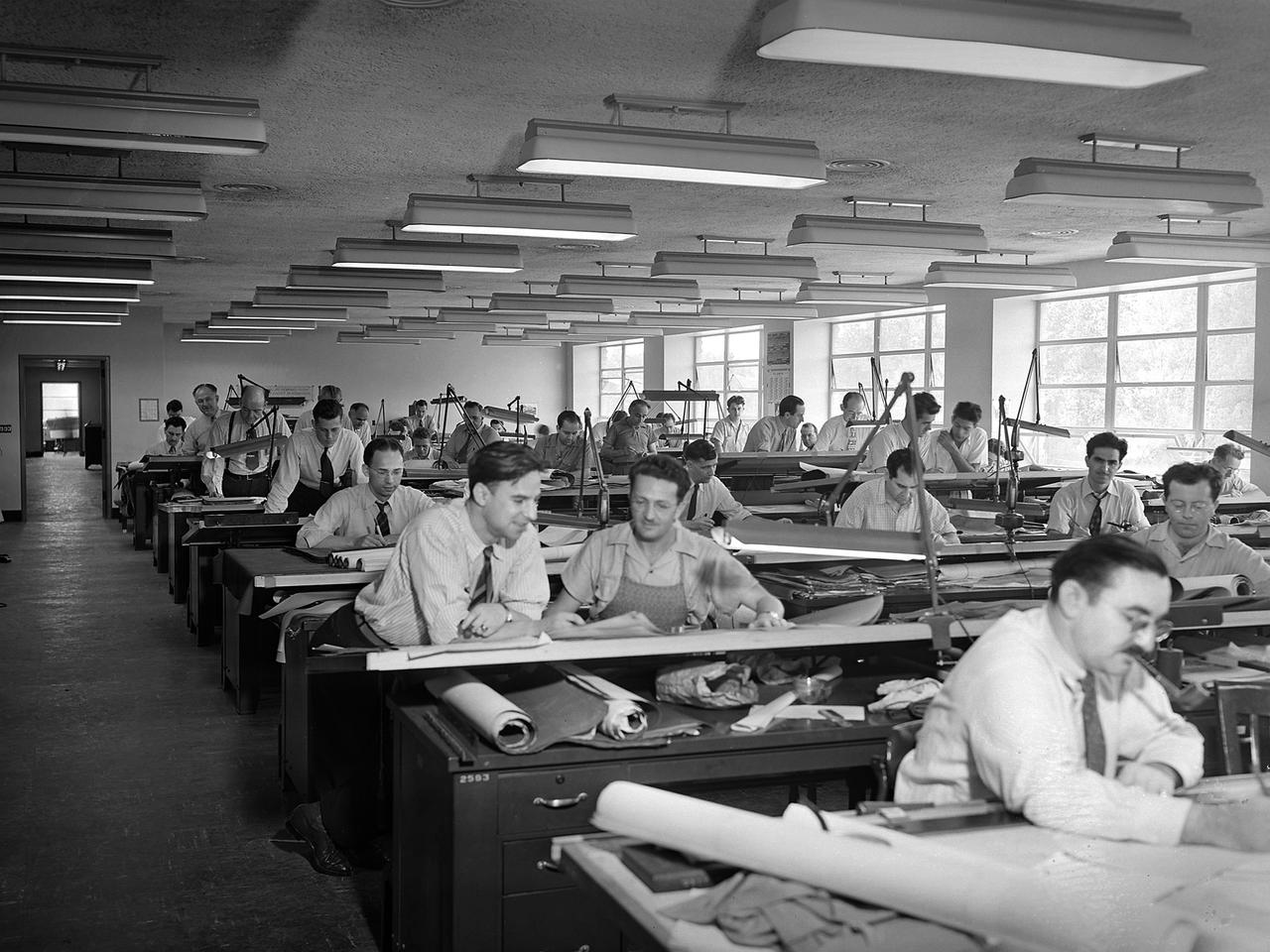
The National Advisory Committee for Aeronautics (NACA) Aircraft Engine Research Laboratory was designed by a group of engineers at the Langley Memorial Aeronautical Laboratory in late 1940 and 1941. Under the guidance of Ernest Whitney, the men worked on drawings and calculations in a room above Langley’s Structural Research Laboratory. The main Aircraft Engine Research Laboratory design group originally consisted of approximately 30 engineers and draftsmen, but there were smaller groups working separately on specific facilities. The new engine lab would have six principal buildings: the Engine Research Building, hangar, Fuels and Lubricants Building, Administration Building, Propeller Test Stand, and Altitude Wind Tunnel. In December 1941 most of those working on the project transferred to Cleveland from Langley. Harrison Underwood and Charles Egan led 18 architectural, 26 machine equipment, 3 structural and 10 mechanical draftsmen. Initially these staff members were housed in temporary offices in the hangar. As sections of the four-acre Engine Research Building were completed in the summer of 1942, the design team began relocating there. The Engine Research Building contained a variety of test cells and laboratories to address virtually every aspect of piston engine research. It also contained a two-story office wing, seen in this photograph that would later house many of the powerplant research engineers.
A Convair F-106B Delta Dart rolls to the right to reveal the two research engines installed under its wings by the National Aeronautics and Space Administration (NASA) Lewis Research Center. Lewis acquired the aircraft in October of 1966 to study inlet and nozzle designs for the supersonic transport engine program. Two General Electric J85 engines were mounted beneath the F-106B’s wings and operated from Mach 1 to 1.5. The right wing always carried reference nozzle for which the performance was known. Six supersonic nozzle variations and two inlets were tested on the left engine. The designs had already been studied in the Lewis wind tunnels, but those tests were limited by shock waves in the tunnels. Most F-106B flights were flown in a 200-mile path over the lake between Buffalo and Sandusky, known as the Lake Erie Corridor. The 1100-mile-per-hour flight took only 11 minutes at an altitude of 30,000 feet. The aircraft almost always returned with a depleted fuel supply so a Visual Flight Rules operation was required. Following the crash of another jet fighter at Lewis in July 1969, the F-106s were stationed at Selfridge Air Force Base in Michigan. NASA pilots flew transport planes each morning to the base before commencing the F-106B missions. After the supersonic transport program was cancelled, the F-106B was used as a test bed for additional engine exhaust nozzle configurations. The F-106B was also used to test inlet configurations for the noise reduction program.
A Bell P-59B Airacomet sits beside the hangar at the National Advisory Committee for Aeronautics (NACA) Lewis Flight Propulsion Laboratory. In 1942 the Bell XP-59A Airacomet became the first jet aircraft in the US. The Airacomet incorporated centrifugal turbojet engines that were based on British plans secretly brought to the US in 1941. A Bell test pilot flew the XP-59A for the first time at Muroc Lake, California in October 1942. The General Electric I-16 engines proved to be problematic. In an effort to increase the engine performance, an Airacomet was secretly brought to Cleveland in early 1944 for testing in the Altitude Wind Tunnel. A series of tunnel investigations in February and March resulted in a 25-percent increase in the I-16 engine’s performance. Nonetheless, Bell’s 66 Airacomets never made it into combat. A second, slightly improved Airacomet, a P-59B, was transferred to NACA Lewis just after the war in September 1945. The P-59B was used over the next three years to study general jet thrust performance and thrust augmentation devices such as afterburners and water/alcohol injection. The P-59B flights determined the proper alcohol and water mixture and injection rate to produce a 21-percent increase in thrust. Since the extra boost would be most useful for takeoffs, a series of ground-based tests with the aircraft ensued. It was determined that the runway length for takeoffs could be reduced by as much as 15 percent. The P-59B used for the tests is now on display at the Air Force Museum at Wright Patterson.
This diagram shows a hydrogen fuel system designed by researchers at the National Advisory Committee for Aeronautics (NACA) Lewis Flight Propulsion Laboratory and installed on a Martin B-57B Canberra aircraft. Lewis researchers accelerated their studies of high energy propellants in the early 1950s. In late 1954, Lewis researchers studied the combustion characteristics of gaseous hydrogen in a turbojet combustor. It was found that the hydrogen provided a very high efficiency. Almost immediately thereafter, Associate Director Abe Silverstein became focused on the possibilities of hydrogen for aircraft propulsion. That fall, Silverstein secured a contract to work with the air force to examine the practicality of liquid hydrogen aircraft. A B-57B Canberra was obtained by the air force especially for this project, referred to as Project Bee. The aircraft was powered by two Wright J65 engines, one of which was modified so that it could be operated using either traditional or liquid hydrogen propellants. The engine and its liquid hydrogen fuel system were tested extensively in the Altitude Wind Tunnel and the Four Burner Area test cells in 1955 and 1956. A B-57B flight program was planned to test the system on an actual aircraft. The aircraft would take off using jet fuel, switch to liquid hydrogen while over Lake Erie, then after burning the hydrogen supply switch back to jet fuel for the landing. The third test flight, in February 1957, was a success, and the ensuing B-57B flights remain the only demonstration of hydrogen-powered aircraft.

A mechanic works on a General Electric I-40 turbojet at the National Advisory Committee for Aeronautics (NACA) Lewis Flight Propulsion Laboratory. The military selected General Electric’s West Lynn facility in 1941 to secretly replicate the centrifugal turbojet engine designed by British engineer Frank Whittle. General Electric’s first attempt, the I-A, was fraught with problems. The design was improved somewhat with the subsequent I-16 engine. It was not until the engine's next reincarnation as the I-40 in 1943 that General Electric’s efforts paid off. The 4000-pound thrust I-40 was incorporated into the Lockheed Shooting Star airframe and successfully flown in June 1944. The Shooting Star became the US’s first successful jet aircraft and the first US aircraft to reach 500 miles per hour. The NACA’s Lewis Flight Propulsion Laboratory studied all of General Electric’s centrifugal turbojets both during World War II and afterwards. The entire Shooting Star aircraft was investigated in the Altitude Wind Tunnel during 1945. The researchers studied the engine compressor performance, thrust augmentation using a water injection, and compared different fuel blends in a single combustor. The mechanic in this photograph is inserting a combustion liner into one of the 14 combustor cans. The compressor, which is not yet installed in this photograph, pushed high pressure air into these combustors. There the air mixed with the fuel and was heated. The hot air was then forced through a rotating turbine that powered the engine before being expelled out the nozzle to produce thrust.

A Lockheed P-80 Shooting Star jet aircraft on the tarmac at the National Advisory Committee for Aeronautics (NACA) NACA Lewis Flight Propulsion Laboratory in Cleveland, Ohio. The Air Force aircraft was participating in the 1946 National Air Races over Labor Day weekend. The air races were held at the Cleveland Municipal Airport seven times between 1929 and 1939. The events included long distance, sprint, and circuit competitions, as well as aeronautical displays, demonstrations, and celebrities. The air races were suspended indefinitely in 1940 for a variety of reasons, including the start of World War II in Europe. The nature of the National Air Races changed dramatically when the event resumed in 1946. The introduction of jet aircraft, primarily the Lockheed P-80 seen here, required an entire separate division for each event. Since military pilots were the only ones with any jet aircraft experience, only they could participate in those divisions. In addition, the performance and quantity of commercially manufactured piston aircraft had increased dramatically during the war. By 1946, the custom-built racing aircraft that made the pre-war races so interesting were no longer present. The P-80 was the first US-designed and US-manufactured jet aircraft. Early models were tested during the war in NACA Lewis’ Altitude Wind Tunnel. A modified P-80 set the world’s speed record at the 1947 air races by achieving 620 miles per hour.
Researcher John Sloop briefs visitors on his latest rocket engine research during the 1947 Inspection at the National Advisory Committee for Aeronautics (NACA) Lewis Flight Propulsion Laboratory. The NACA had been hosting annual Aircraft Engineering Conferences, better known as Inspections, since 1926. Individuals from the manufacturing industry, military, and university settings were invited to tour the NACA laboratories. There were a series of stops on the tour, mostly at test facilities, where researchers would brief the group on the latest efforts in their particular field. The Inspections grew in size and scope over the years and by the mid-1940s required multiple days. The three-day 1947 Inspection was the first time the event was held at NACA Lewis. Over 800 scientists, industrialists, and military leaders attended the three-day event. Talks were given at the Altitude Wind Tunnel, Four Burner Area, Engine Research Building, and other facilities. An array of topics were discussed, including full-scale engine testing, ramjets, axial-flow compressors, turbojets, fuels, icing, and materials. The NACA Lewis staff and their families were able to view the same presentations after the Inspection was over. Sloop, a researcher in the Fuels and Thermodynamics Division, briefed visitors on NACA Lewis’ early research in rocket engine propellants, combustion, and cooling. This early NACA Lewis work led to the development of liquid hydrogen as a viable propellant in the late 1950s.
![Astronaut Neil Armstrong examines a Vertical and Short Takeoff and Landing test setup in the 9- by 15-Foot Low Speed Wind Tunnel at the National Aeronautics and Space Administration (NASA) Lewis Research Center. Armstrong spent February 6, 1970 at Lewis attending technical meetings and touring some facilities. Just six months after Armstrong had returned from the moon looming agency budget cuts were already a concern in his comments. He noted that NASA had to “find a balanced approach…and [make] aggressive use of available facilities.” Armstrong spent four months at the center as a research pilot in 1955. Armstrong had served as a Navy pilot during the Korean War then earned a degree in aeronautical engineering at Purdue University. He was recruited by Lewis while at Purdue and began at the center shortly after graduation. During his brief tenure in Cleveland Armstrong served as both a test pilot and research engineer, primarily involved with icing research. In his role as research pilot Armstrong also flew a North American F-82 Twin Mustang over the ocean near Wallops Island to launch small instrumented rockets from high altitudes down into the atmosphere to obtain high Mach numbers. After four months in Cleveland a position opened up at what is today the Dryden Flight Research Center. Armstrong’s career in Cleveland officially ended on June 30, 1955.](https://images-assets.nasa.gov/image/GRC-1970-C-00473/GRC-1970-C-00473~medium.jpg)
Astronaut Neil Armstrong examines a Vertical and Short Takeoff and Landing test setup in the 9- by 15-Foot Low Speed Wind Tunnel at the National Aeronautics and Space Administration (NASA) Lewis Research Center. Armstrong spent February 6, 1970 at Lewis attending technical meetings and touring some facilities. Just six months after Armstrong had returned from the moon looming agency budget cuts were already a concern in his comments. He noted that NASA had to “find a balanced approach…and [make] aggressive use of available facilities.” Armstrong spent four months at the center as a research pilot in 1955. Armstrong had served as a Navy pilot during the Korean War then earned a degree in aeronautical engineering at Purdue University. He was recruited by Lewis while at Purdue and began at the center shortly after graduation. During his brief tenure in Cleveland Armstrong served as both a test pilot and research engineer, primarily involved with icing research. In his role as research pilot Armstrong also flew a North American F-82 Twin Mustang over the ocean near Wallops Island to launch small instrumented rockets from high altitudes down into the atmosphere to obtain high Mach numbers. After four months in Cleveland a position opened up at what is today the Dryden Flight Research Center. Armstrong’s career in Cleveland officially ended on June 30, 1955.
The first of three X-43A hypersonic research aircraft and its modified Pegasus® booster rocket recently underwent combined systems testing while mounted to NASA's NB-52B carrier aircraft at the Dryden Flight Research Center, Edwards, California. The combined systems test was one of the last major milestones in the Hyper-X research program before the first X-43A flight. One of the major goals of the Hyper-X program is flight validation of airframe-integrated, air-breathing propulsion system, which so far have only been tested in ground facilities, such as wind tunnels. The X-43A flights will be the first actual flight tests of an aircraft powered by a revolutionary supersonic-combustion ramjet ("scramjet") engine capable of operating at hypersonic speeds above Mach 5 (five times the speed of sound). The X-43A design uses the underbody of the aircraft to form critical elements of the engine. The forebody shape helps compress the intake airflow, while the aft section acts as a nozzle to direct thrust. The 12-foot, unpiloted research vehicle was developed and built by MicroCraft Inc., Tullahoma, Tenn., under NASA contract. The booster, built by Orbital Sciences Corp., Dulles, Va., will accelerate the X-43A after the X-43A/booster "stack" is air-launched from NASA's venerable NB-52 mothership. The X-43A will separate from the rocket at a predetermined altitude and speed and fly a pre-programmed trajectory, conducting aerodynamic and propulsion experiments until it descends into the Pacific Ocean. Three research flights are planned, two at Mach 7 and one at Mach 10.