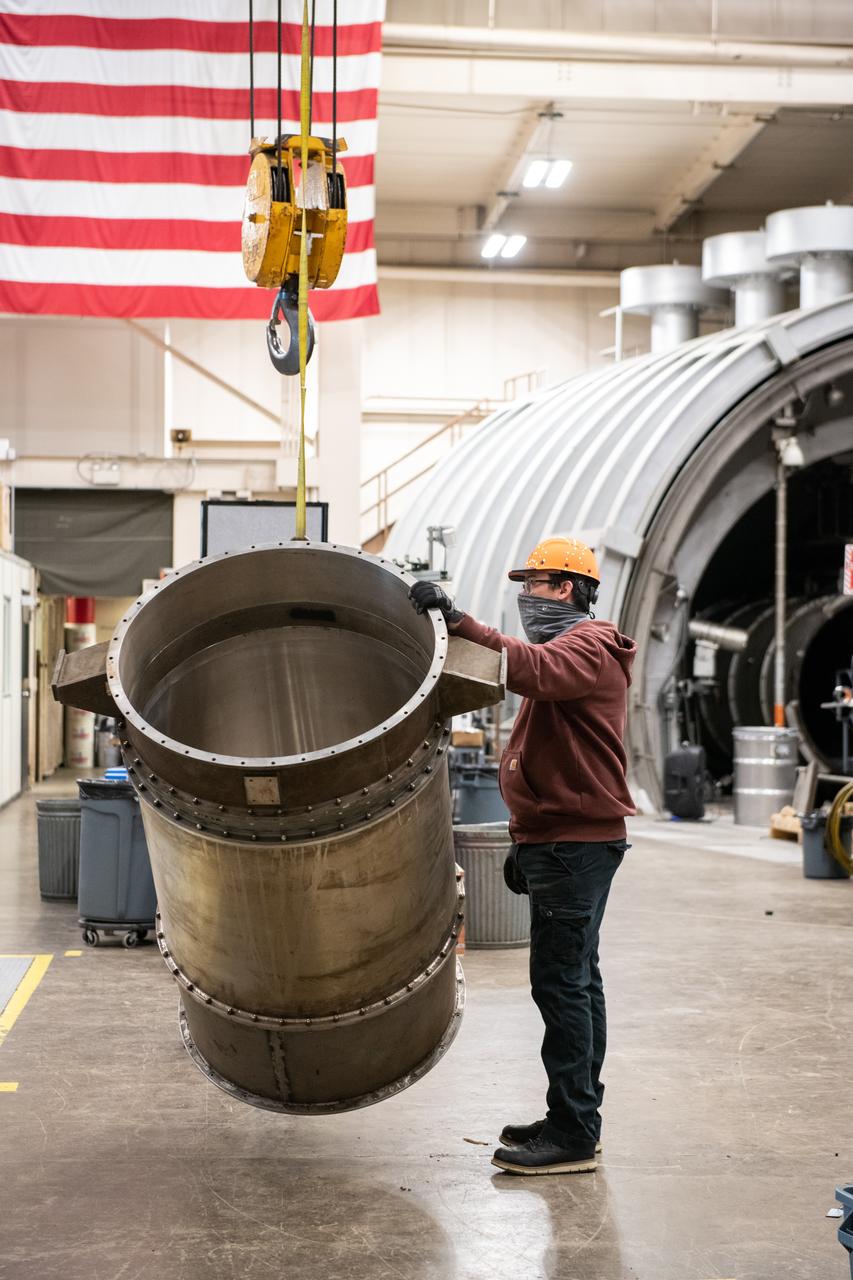
American Society of Mechanical Engineers, ASME Nozzle Test at Propulsion Systems Laboratory, PSL
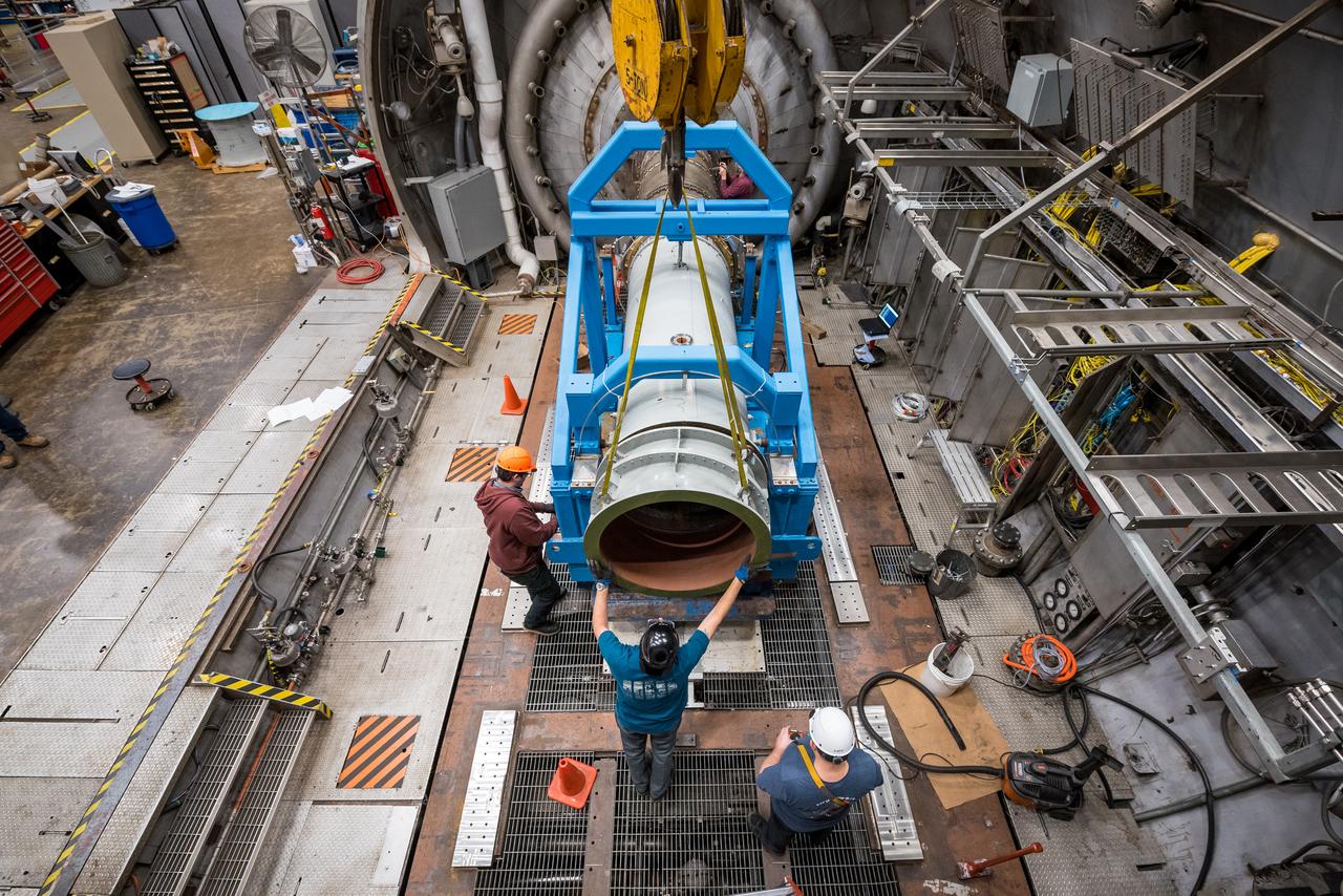
American Society of Mechanical Engineers, ASME Nozzle Test at Propulsion Systems Laboratory, PSL
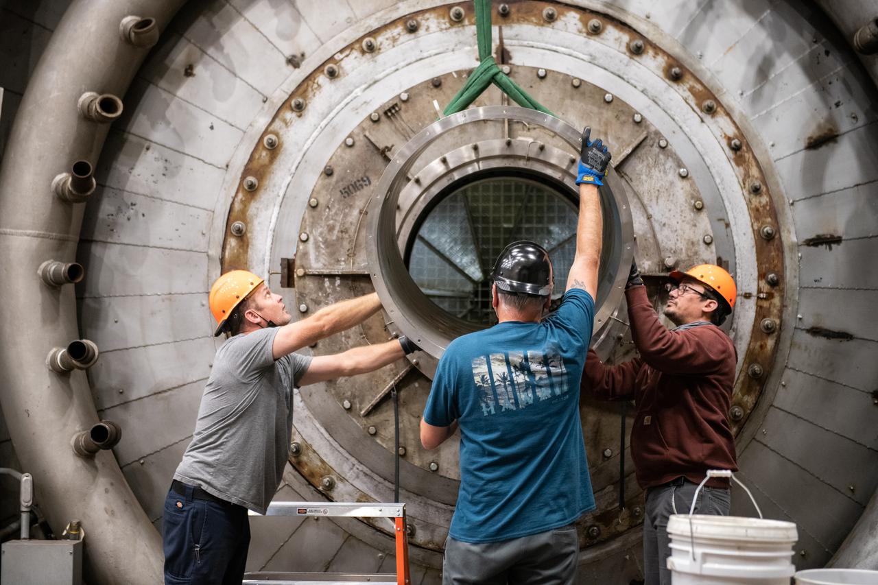
American Society of Mechanical Engineers, ASME Nozzle Test at Propulsion Systems Laboratory, PSL Documentation Photographs
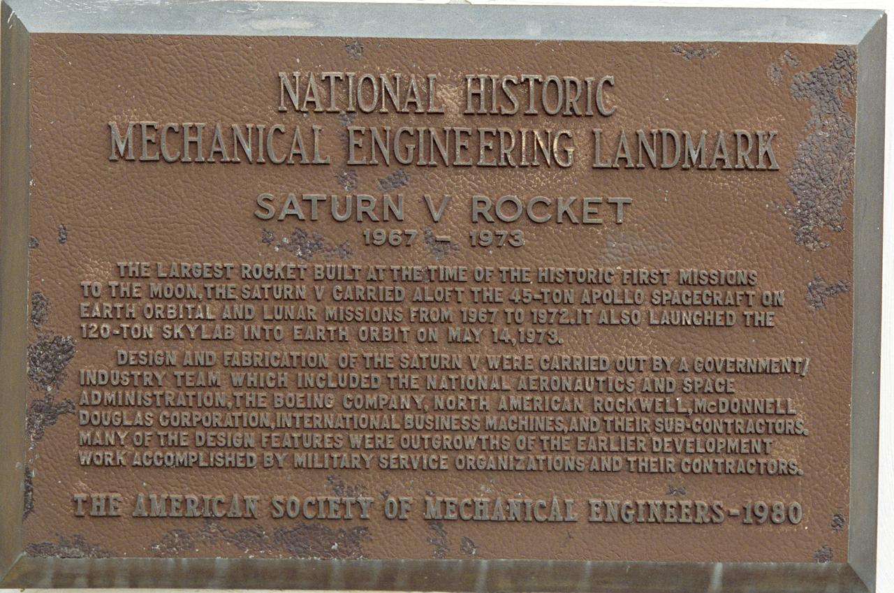
This plaque, located on the grounds of Marshall Space Flight Center in Huntsville, Alabama,commemorates the designation of the Saturn V Rocket as a National Historic Mechanical Engineering Landmark by the American Society of Mechanical Engineers in 1980.
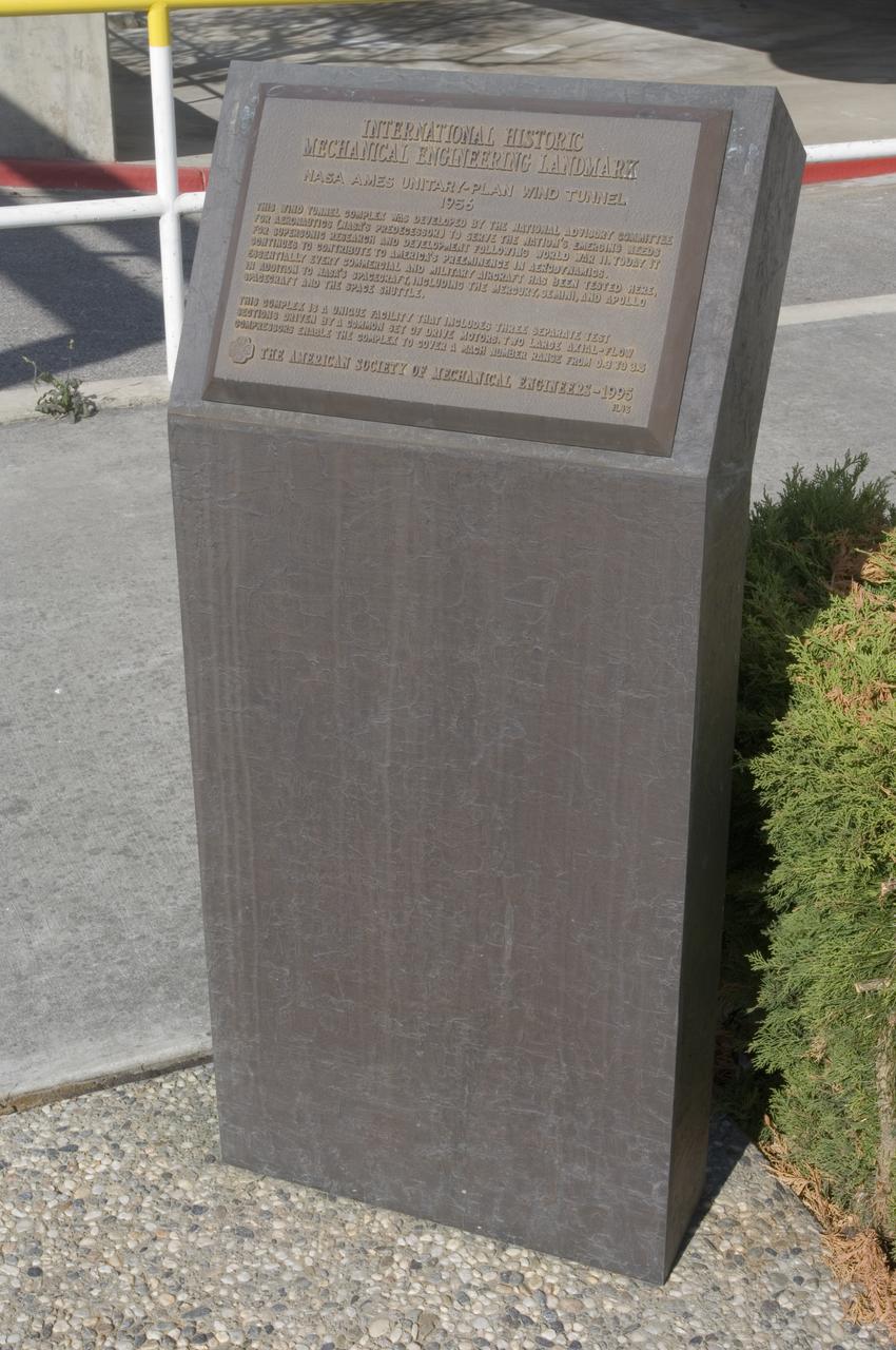
Ames and Moffett Field (MFA) historical sites and memorials Unitary Plan Wind Tunned plaza; display and historical site plaques with the NASA logo on the Wind Tunnel valve as a backdrop. shown is the Unitary International Historic Mechanical Engineering Landmark Dedication plaque (American Society of Mechanical Engineers) May 5, 1995
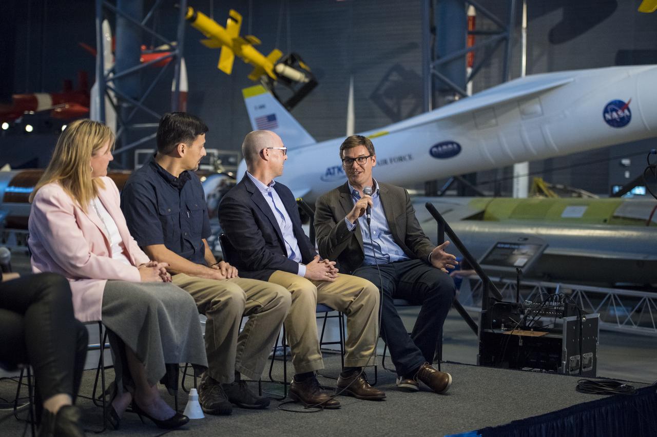
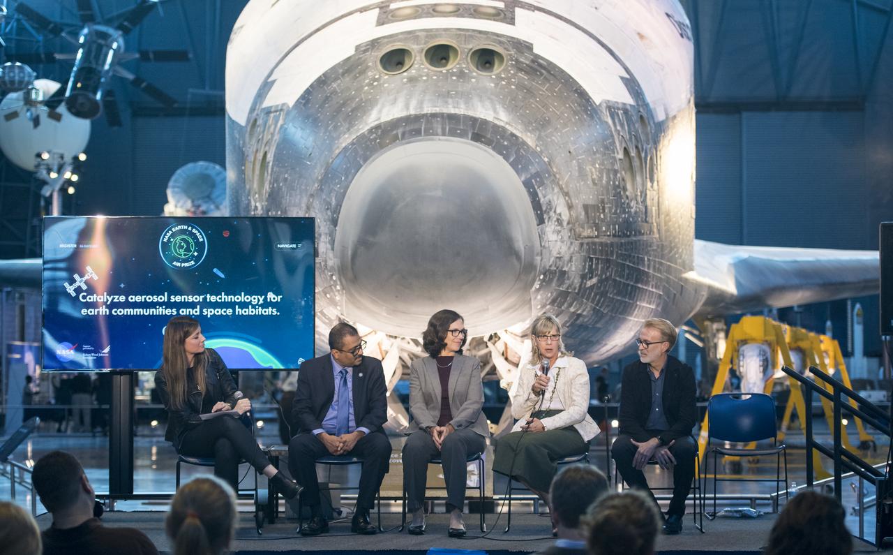
Paul Scott, interim executive director, The American Society of Mechanical Engineers (ASME), speaks on a panel on "igniting NOVA K-12 engineering and maker education", at a pop-up makerspace hosted by Future Engineers with support from NASA and ASME, at the Steven F. Udvar-Hazy Center, Thursday, September 21, 2017 in Chantilly, Virginia. Participants were able to create digital 3D models using Autodesk Tinkercad and watch objects being printed with Makerbot 3D printers. Photo Credit: (NASA/Aubrey Gemignani)
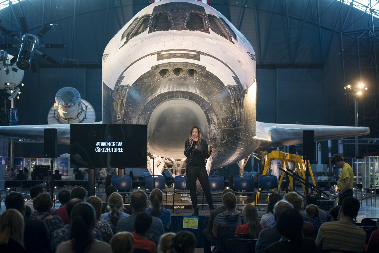
Founder and CEO of Future Engineers, Deanne Bell, speaks at a pop-up makerspace hosted by Future Engineers with support from NASA and The American Society of Mechanical Engineers (ASME), at the Steven F. Udvar-Hazy Center, Thursday, September 21, 2017 in Chantilly, Virginia. Participants were able to create digital 3D models using Autodesk Tinkercad and watch objects being printed with Makerbot 3D printers. Photo Credit: (NASA/Aubrey Gemignani)

Ryan Heitz, co-founder and head of school, Ideaventions Academy, speaks on a panel on "igniting NOVA K-12 engineering and maker education", at a pop-up makerspace hosted by Future Engineers with support from NASA and The American Society of Mechanical Engineers (ASME), at the Steven F. Udvar-Hazy Center, Thursday, September 21, 2017 in Chantilly, Virginia. Participants were able to create digital 3D models using Autodesk Tinkercad and watch objects being printed with Makerbot 3D printers. Photo Credit: (NASA/Aubrey Gemignani)
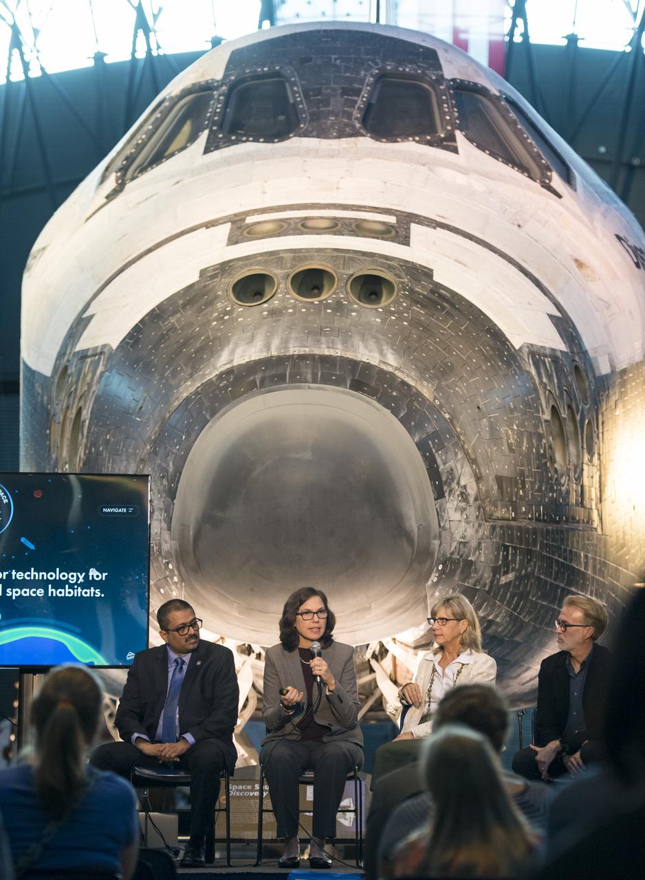
Marit Meyer, research aerospace engineer, Aerosol Science and Instrumentation, NASA, speaks on a panel on improving air quality for health in space and on Earth, at a pop-up makerspace hosted by Future Engineers with support from NASA and The American Society of Mechanical Engineers (ASME), at the Steven F. Udvar-Hazy Center, Thursday, September 21, 2017 in Chantilly, Virginia. Participants were able to create digital 3D models using Autodesk Tinkercad and watch objects being printed with Makerbot 3D printers. Photo Credit: (NASA/Aubrey Gemignani)
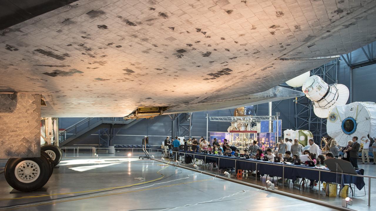
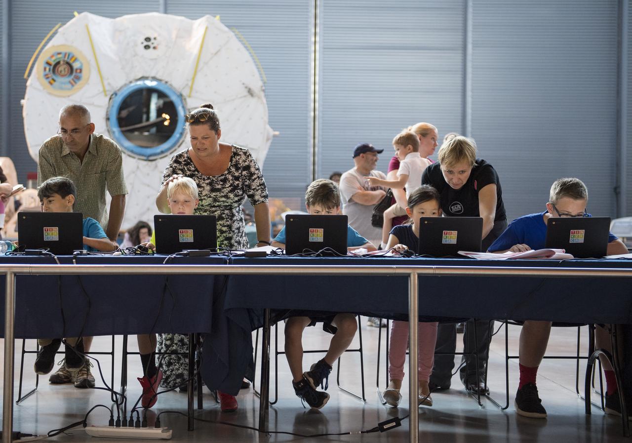
Future Engineers with support from NASA and The American Society of Mechanical Engineers (ASME), hosted a future engineers pop-up makerspace where youth were able to create digital 3D models using Autodesk Tinkercad and watch objects being printed with Makerbot 3D printers, at the Steven F. Udvar-Hazy Center, Thursday, September 21, 2017 in Chantilly, Virginia. Photo Credit: (NASA/Aubrey Gemignani)
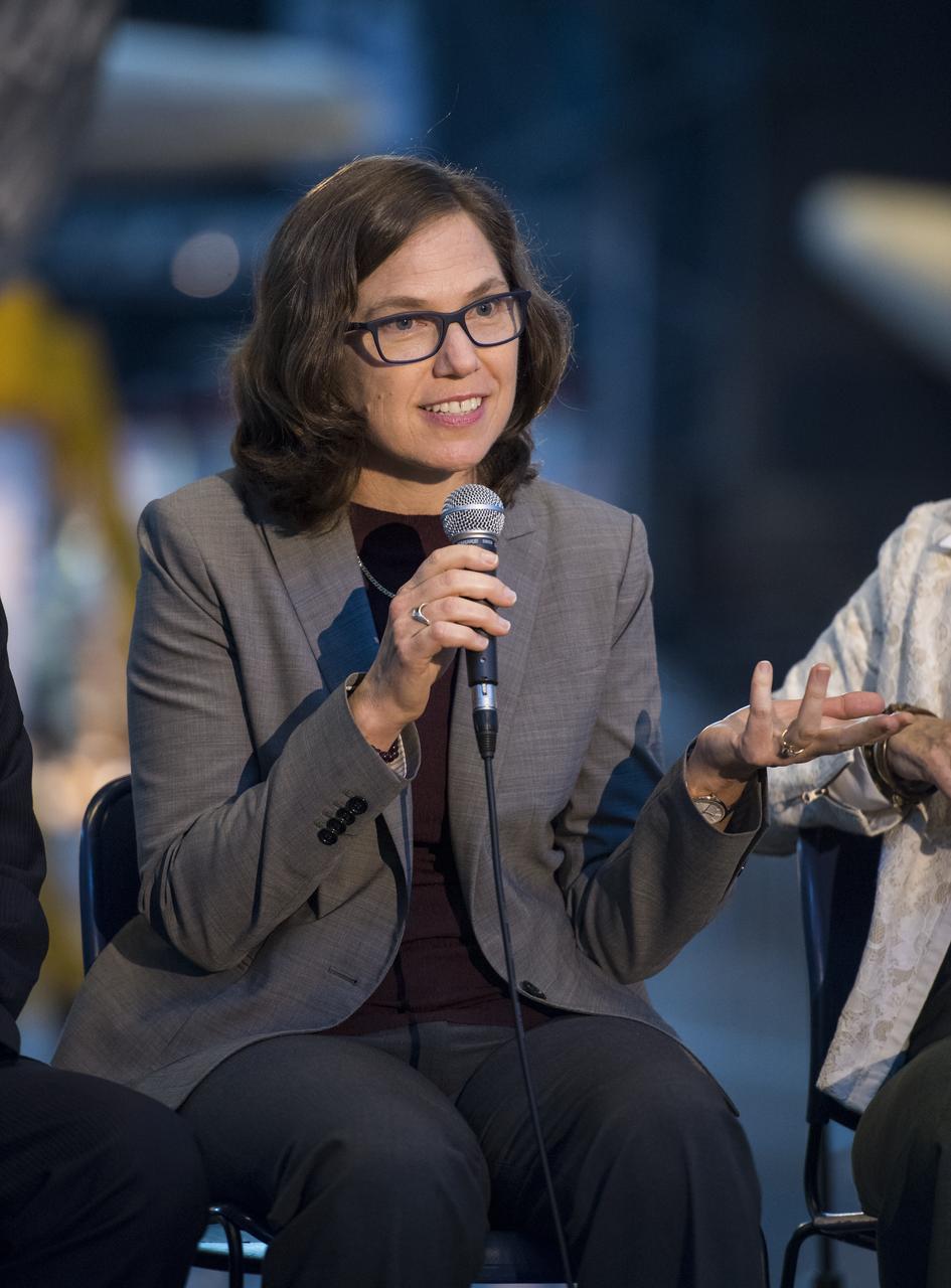
Marit Meyer, research aerospace engineer, Aerosol Science and Instrumentation, NASA, speaks on a panel on improving air quality for health in space and on Earth, at a pop-up makerspace hosted by Future Engineers with support from NASA and The American Society of Mechanical Engineers (ASME), at the Steven F. Udvar-Hazy Center, Thursday, September 21, 2017 in Chantilly, Virginia. Participants were able to create digital 3D models using Autodesk Tinkercad and watch objects being printed with Makerbot 3D printers. Photo Credit: (NASA/Aubrey Gemignani)

Michael Painter, senior program officer, Robert Wood Johnson Foundation, speaks on a panel on improving air quality for health in space and on Earth, at a pop-up makerspace hosted by Future Engineers with support from NASA and The American Society of Mechanical Engineers (ASME), at the Steven F. Udvar-Hazy Center, Thursday, September 21, 2017 in Chantilly, Virginia. Participants were able to create digital 3D models using Autodesk Tinkercad and watch objects being printed with Makerbot 3D printers. Photo Credit: (NASA/Aubrey Gemignani)
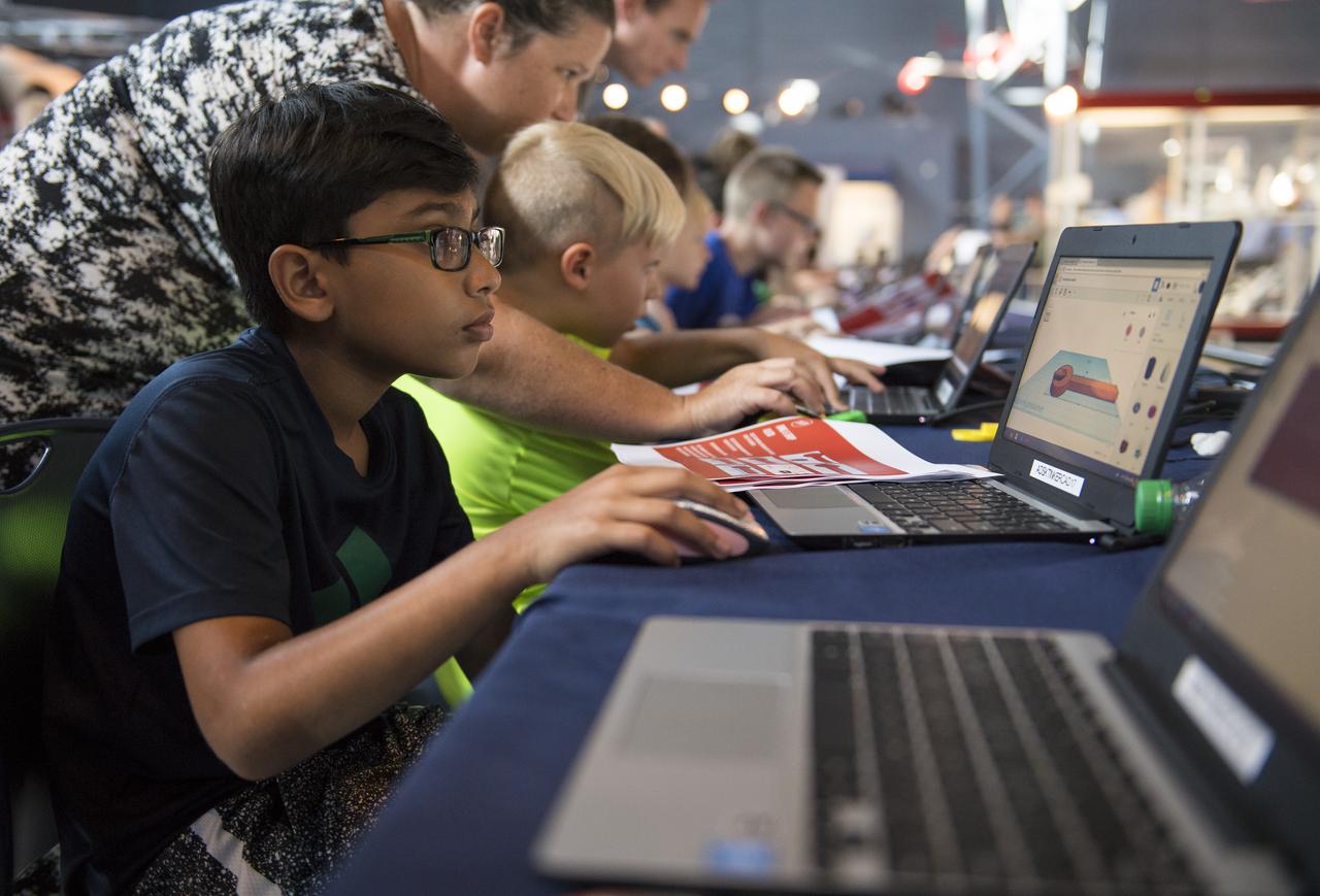
A participant creates digital 3D models using Autodesk Tinkercad in the Two for the Crew Challenge at a pop-up makerspace held by Future Engineers, with support from NASA and The American Society of Mechanical Engineers (ASME), at the Steven F. Udvar-Hazy Center, Thursday, September 21, 2017 in Chantilly, Virginia. Participants had the opportunity to create digital 3D models and watch objects being printed with Makerbot 3D printers. Photo Credit: (NASA/Aubrey Gemignani)
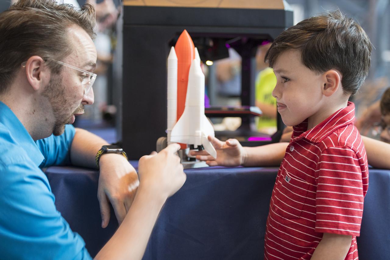
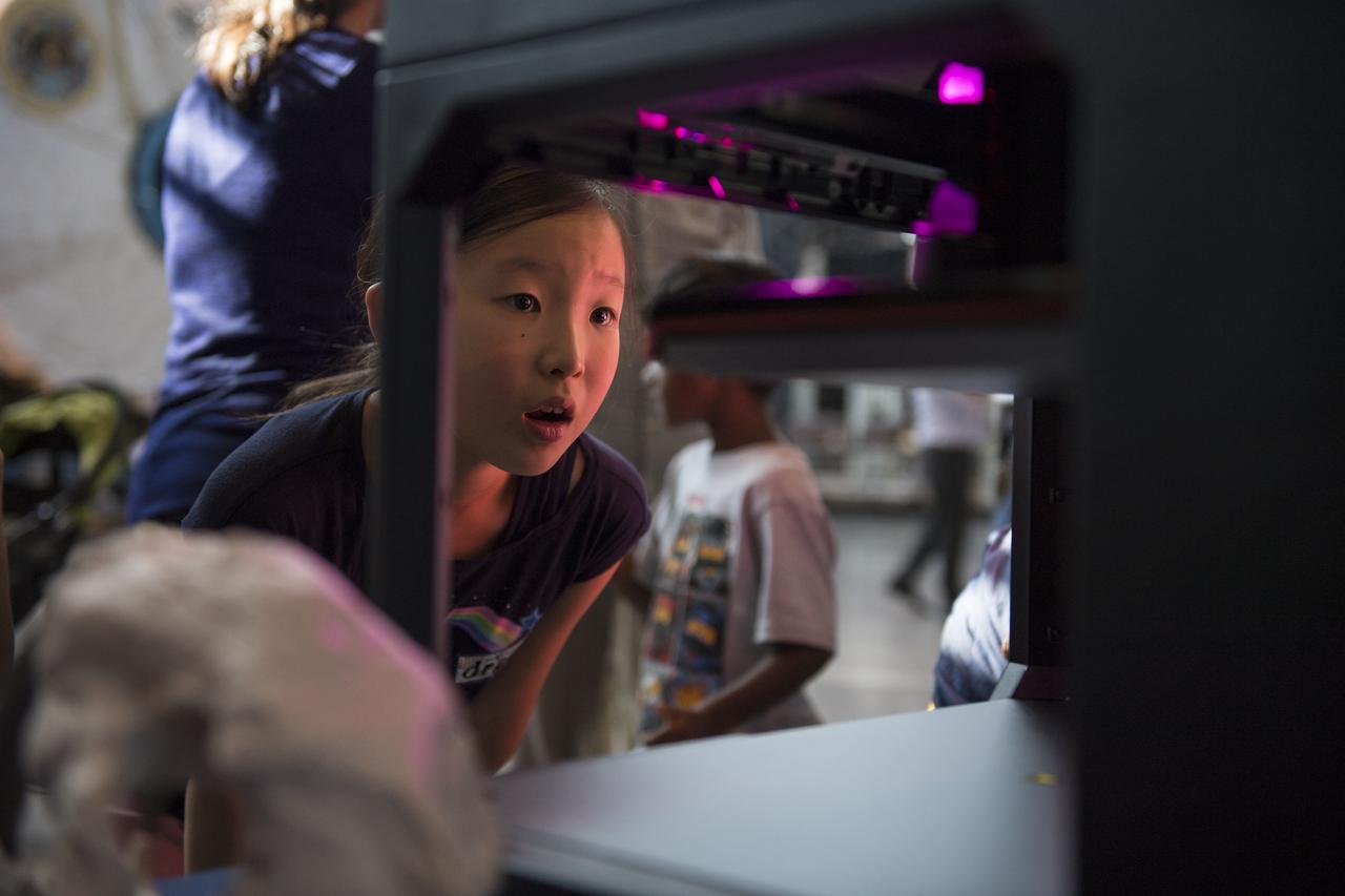
A visitor learns about 3D printing at a pop-up makerspace held by Future Engineers with support from NASA and The American Society of Mechanical Engineers (ASME), at the Steven F. Udvar-Hazy Center, Thursday, September 21, 2017 in Chantilly, Virginia. Participants created digital 3D models using Autodesk Tinkercad and watched objects being printed with Makerbot 3D printers. Photo Credit: (NASA/Aubrey Gemignani)
A visitor watches as a rocket is printed by a Makerbot 3D printer at a pop-up makerspace held by Future Engineers, with support from NASA and The American Society of Mechanical Engineers (ASME), at the Steven F. Udvar-Hazy Center, Thursday, September 21, 2017 in Chantilly, Virginia. Participants created digital 3D models using Autodesk Tinkercad and watched objects being printed with Makerbot 3D printers. Photo Credit: (NASA/Aubrey Gemignani)

A young audience member asks the panel a question during a discussion on improving air quality for health in space and on Earth, at a pop-up makerspace hosted by Future Engineers with support from NASA and The American Society of Mechanical Engineers (ASME), at the Steven F. Udvar-Hazy Center, Thursday, September 21, 2017 in Chantilly, Virginia. Participants were able to create digital 3D models using Autodesk Tinkercad and watch objects being printed with Makerbot 3D printers. Photo Credit: (NASA/Aubrey Gemignani)
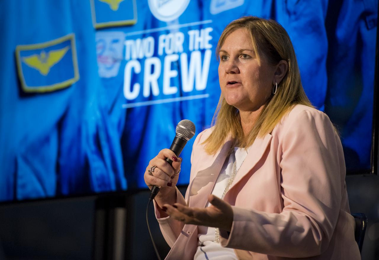
Lynn Buquo, manager, NASA Center of Excellence for Collaborative Innovation, speaks on a panel on improving air quality for health in space and on Earth, at a pop-up makerspace hosted by Future Engineers with support from NASA and The American Society of Mechanical Engineers (ASME), at the Steven F. Udvar-Hazy Center, Thursday, September 21, 2017 in Chantilly, Virginia. Participants were able to create digital 3D models using Autodesk Tinkercad and watch objects being printed with Makerbot 3D printers. Photo Credit: (NASA/Aubrey Gemignani)
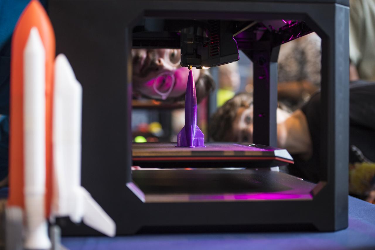
Visitors watch as a rocket is printed by a Makerbot 3D printer at a pop-up makerspace held by Future Engineers, with support from NASA and The American Society of Mechanical Engineers (ASME), at the Steven F. Udvar-Hazy Center, Thursday, September 21, 2017 in Chantilly, Virginia. Participants created digital 3D models using Autodesk Tinkercad and watched objects being printed with Makerbot 3D printers. Photo Credit: (NASA/Aubrey Gemignani)
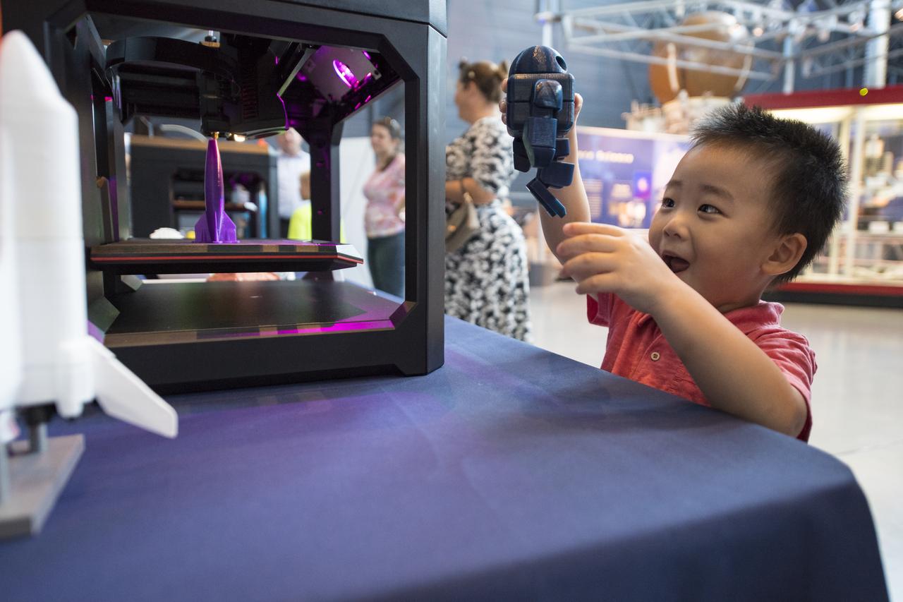
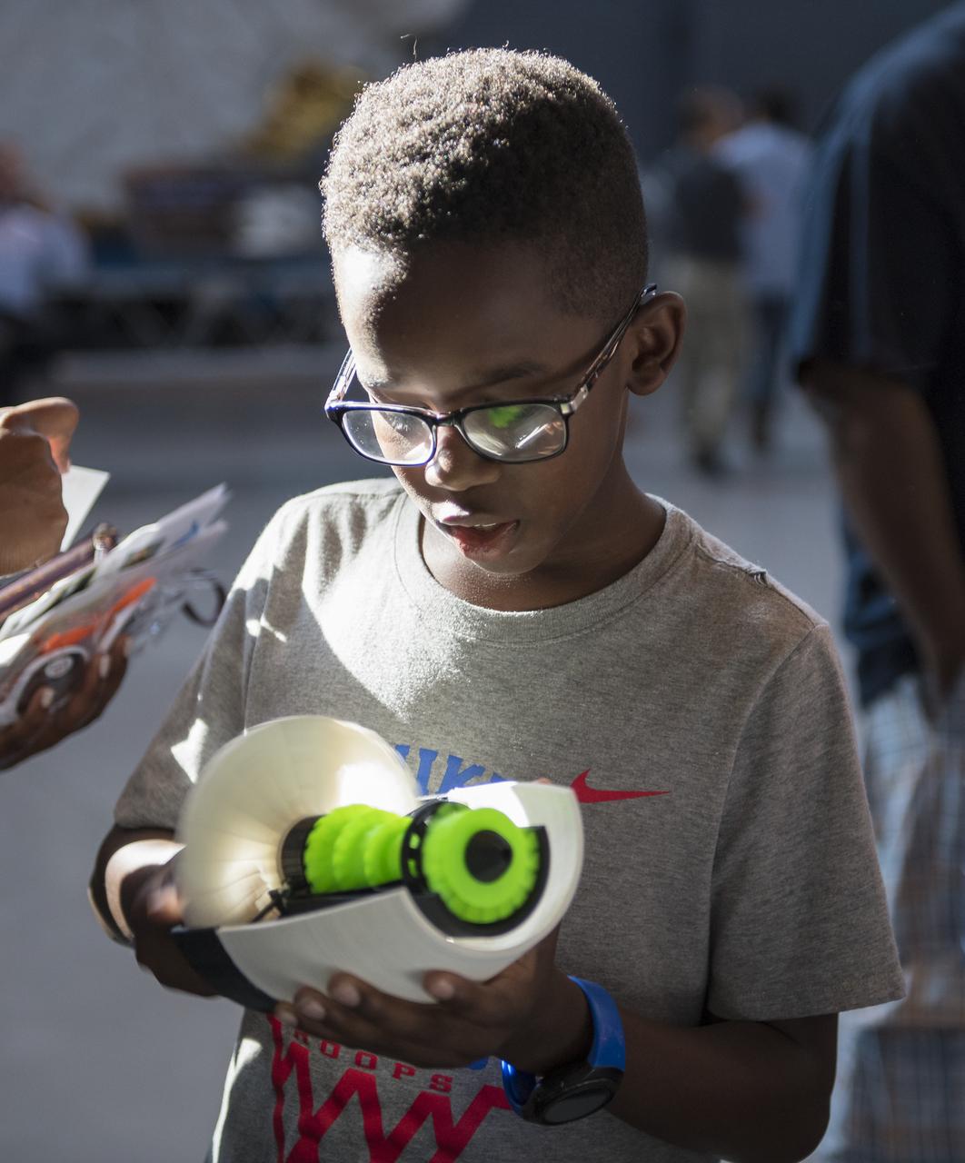
A visitor plays with a robot printed by a 3D printer at a pop-up makerspace held by Future Engineers with support from NASA and The American Society of Mechanical Engineers (ASME), at the Steven F. Udvar-Hazy Center, Thursday, September 21, 2017 in Chantilly, Virginia. Participants created digital 3D models using Autodesk Tinkercad and watched objects being printed with Makerbot 3D printers. Photo Credit: (NASA/Aubrey Gemignani)
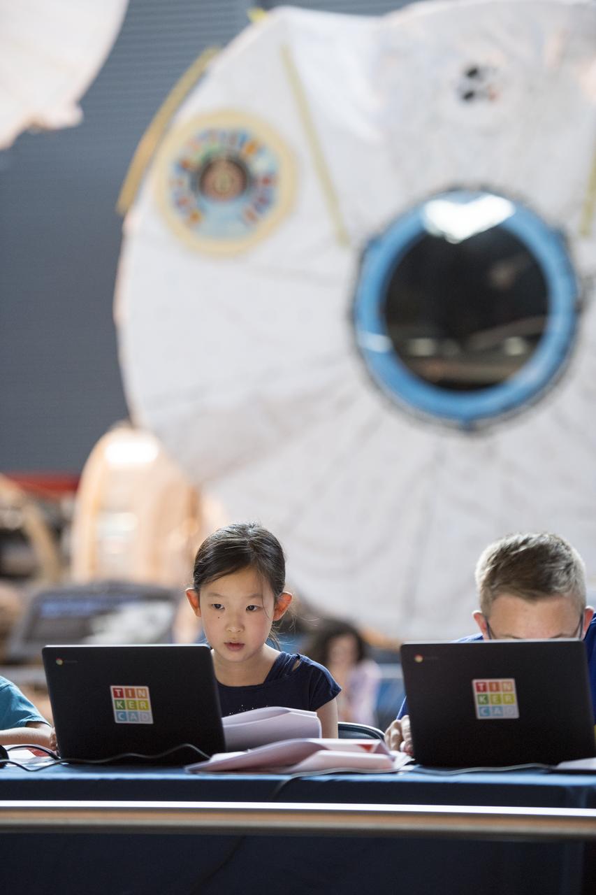
A participant creates digital 3D models using Autodesk Tinkercad in the Two for the Crew Challenge at a pop-up makerspace held by Future Engineers, with support from NASA and The American Society of Mechanical Engineers (ASME), at the Steven F. Udvar-Hazy Center, Thursday, September 21, 2017 in Chantilly, Virginia. Participants had the opportunity to create digital 3D models and watch objects being printed with Makerbot 3D printers. Photo Credit: (NASA/Aubrey Gemignani)
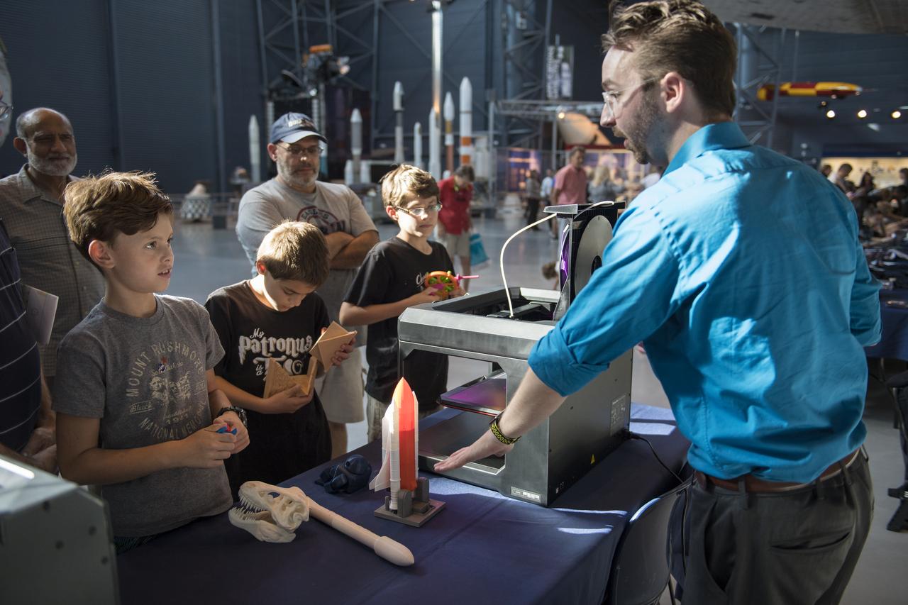
Visitors learn about 3D printing at a pop-up makerspace held by Future Engineers with support from NASA and The American Society of Mechanical Engineers (ASME), at the Steven F. Udvar-Hazy Center, Thursday, September 21, 2017 in Chantilly, Virginia. Participants created digital 3D models using Autodesk Tinkercad and watched objects being printed with Makerbot 3D printers. Photo Credit: (NASA/Aubrey Gemignani)
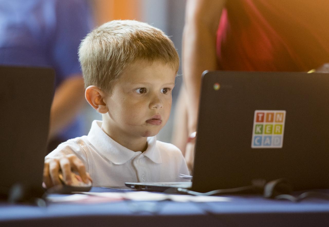
A participant creates digital 3D models using Autodesk Tinkercad in the Two for the Crew Challenge at a pop-up makerspace held by Future Engineers, with support from NASA and The American Society of Mechanical Engineers (ASME), at the Steven F. Udvar-Hazy Center, Thursday, September 21, 2017 in Chantilly, Virginia. Participants had the opportunity to create digital 3D models and watch objects being printed with Makerbot 3D printers. Photo Credit: (NASA/Aubrey Gemignani)
A participant creates digital 3D models using Autodesk Tinkercad in the Two for the Crew Challenge at a pop-up makerspace held by Future Engineers, with support from NASA and The American Society of Mechanical Engineers (ASME), at the Steven F. Udvar-Hazy Center, Thursday, September 21, 2017 in Chantilly, Virginia. Participants had the opportunity to create digital 3D models and watch objects being printed with Makerbot 3D printers. Photo Credit: (NASA/Aubrey Gemignani)
A participant examines a 3D printed object at a pop-up makerspace held by Future Engineers with support from NASA and The American Society of Mechanical Engineers (ASME), at the Steven F. Udvar-Hazy Center, Thursday, September 21, 2017 in Chantilly, Virginia. Participants created digital 3D models using Autodesk Tinkercad and watched objects being printed with Makerbot 3D printers. Photo Credit: (NASA/Aubrey Gemignani)
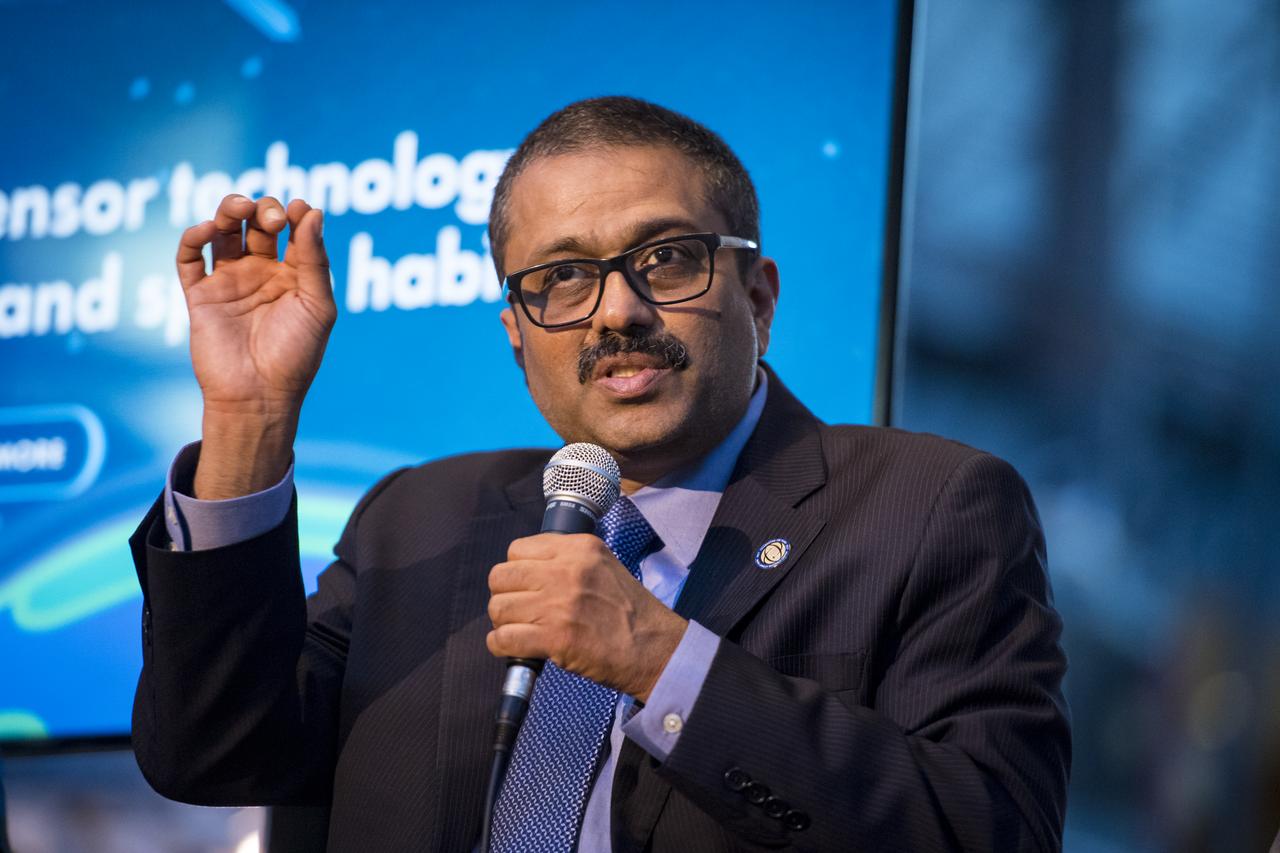
Jitendra Joshi, chief technology advisor, Advanced Exploration Systems, NASA, speaks on a panel on improving air quality for health in space and on Earth, at a pop-up makerspace hosted by Future Engineers with support from NASA and The American Society of Mechanical Engineers (ASME), at the Steven F. Udvar-Hazy Center, Thursday, September 21, 2017 in Chantilly, Virginia. Participants were able to create digital 3D models using Autodesk Tinkercad and watch objects being printed with Makerbot 3D printers. Photo Credit: (NASA/Aubrey Gemignani)

Josh Ajima, instructional facilitator for technology, Loudoun County Public Schools and DesignMakeTeach.com blog, speaks on a panel on "igniting NOVA K-12 engineering and maker education", at a pop-up makerspace hosted by Future Engineers with support from NASA and The American Society of Mechanical Engineers (ASME), at the Steven F. Udvar-Hazy Center, Thursday, September 21, 2017 in Chantilly, Virginia. Participants were able to create digital 3D models using Autodesk Tinkercad and watch objects being printed with Makerbot 3D printers. Photo Credit: (NASA/Aubrey Gemignani)
Ryan Heitz, co-founder and head of school, Ideaventions Academy, second from right, speaks on a panel on "igniting NOVA K-12 engineering and maker education", at a pop-up makerspace hosted by Future Engineers with support from NASA and The American Society of Mechanical Engineers (ASME), at the Steven F. Udvar-Hazy Center, Thursday, September 21, 2017 in Chantilly, Virginia. Participants were able to create digital 3D models using Autodesk Tinkercad and watch objects being printed with Makerbot 3D printers. Photo Credit: (NASA/Aubrey Gemignani)
Barb Gruber, supervisor school programs, Smithsonian National Air and Space Museum, speaks on a panel on "igniting NOVA K-12 engineering and maker education", at a pop-up makerspace hosted by Future Engineers with support from NASA and The American Society of Mechanical Engineers (ASME), at the Steven F. Udvar-Hazy Center, Thursday, September 21, 2017 in Chantilly, Virginia. Participants were able to create digital 3D models using Autodesk Tinkercad and watch objects being printed with Makerbot 3D printers. Photo Credit: (NASA/Aubrey Gemignani)
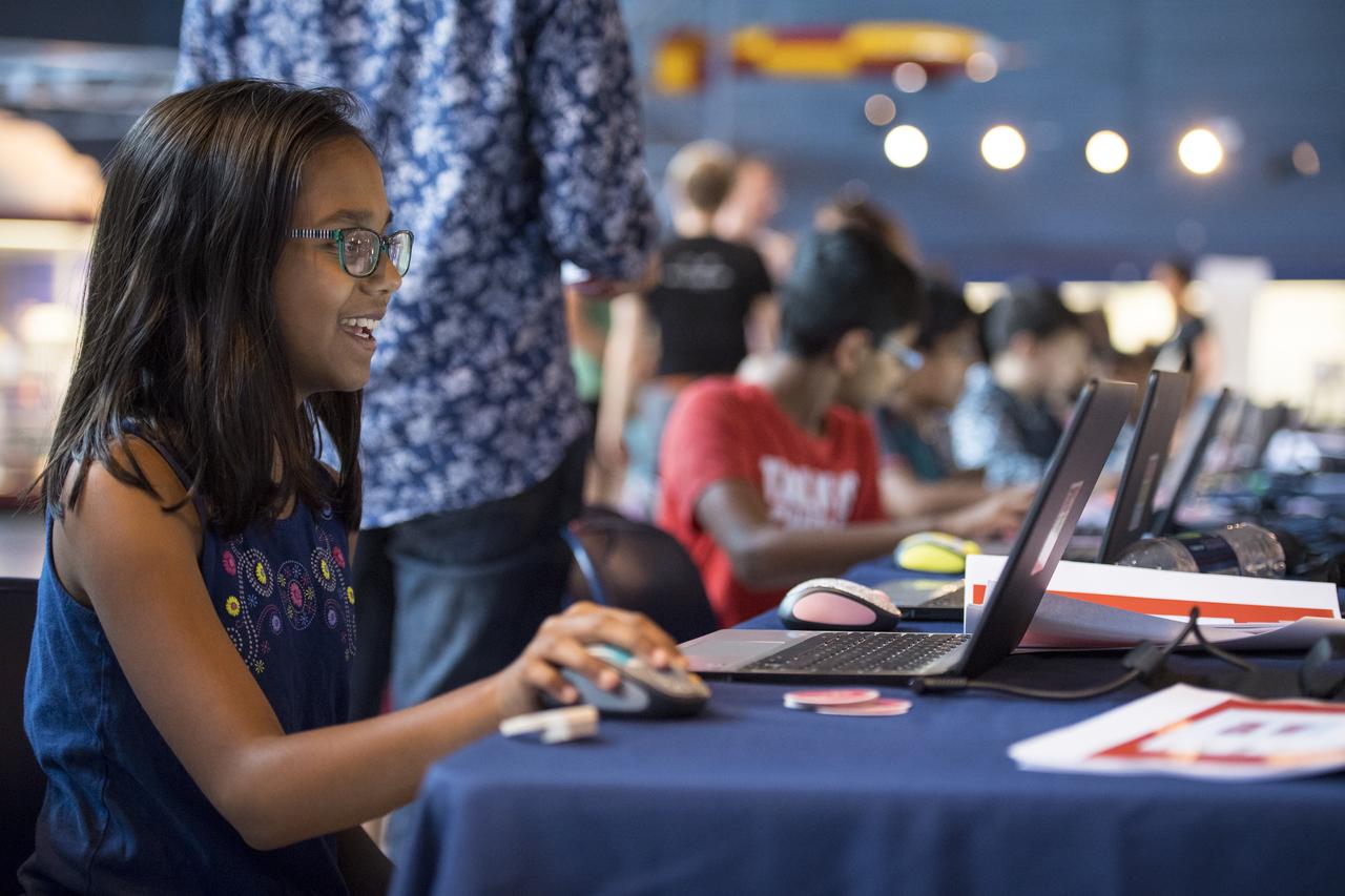
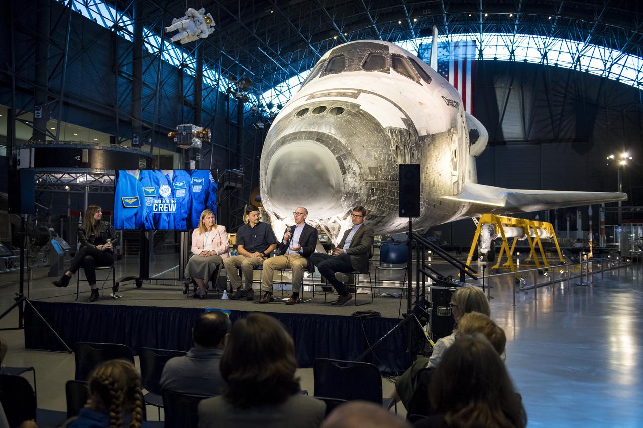
Participants create digital 3D models using Autodesk Tinkercad in the Two for the Crew Challenge at a pop-up makerspace held by Future Engineers, with support from NASA and The American Society of Mechanical Engineers (ASME), at the Steven F. Udvar-Hazy Center, Thursday, September 21, 2017 in Chantilly, Virginia. Participants had the opportunity to create digital 3D models and watch objects being printed with Makerbot 3D printers. The winner of the Two for the Crew challenge will have their design printed on the International Space Station. Photo Credit: (NASA/Aubrey Gemignani)
Originally the Rendezvous was used by the astronauts preparing for Gemini missions. The Rendezvous Docking Simulator was then modified and used to develop docking techniques for the Apollo program. This picture shows a later configuration of the Apollo docking with the LEM target. A.W. Vogeley described the simulator as follows: The Rendezvous Docking Simulator and also the Lunar Landing Research Facility are both rather large moving-base simulators. It should be noted, however, that neither was built primarily because of its motion characteristics. The main reason they were built was to provide a realistic visual scene. A secondary reason was that they would provide correct angular motion cues (important in control of vehicle short-period motions) even though the linear acceleration cues would be incorrect. -- Published in A.W. Vogeley, Piloted Space-Flight Simulation at Langley Research Center, Paper presented at the American Society of Mechanical Engineers, 1966 Winter Meeting, New York, NY, November 27 - December 1, 1966.
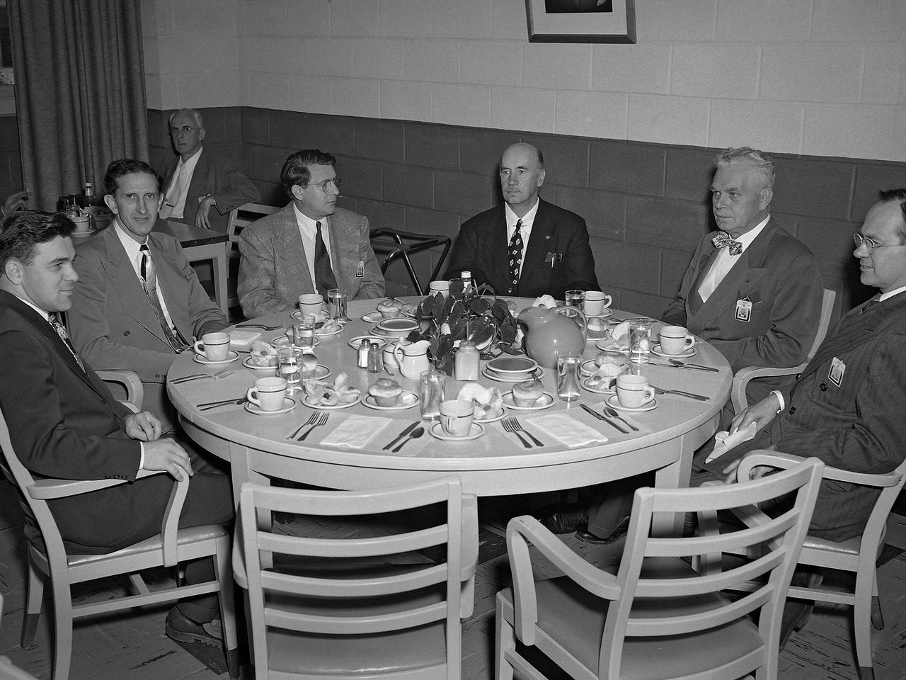
Dr. Igor Sikorsky, fourth from the left, visits the National Advisory Committee for Aeronautics (NACA) Lewis Flight Propulsion Laboratory in Cleveland, Ohio. The legendary Russian-born aviation pioneer visited NACA Lewis several times during the 1940s and 1950s. In 1946 Sikorsky arrived at Lewis for the 1946 National Air Races, which included demonstrations by five of his helicopters. NACA flight mechanic Joseph Sikosky personally escorted Sikorsky during the visit. Sikorsky frequently addressed local professional organizations, such as the American Society of Mechanical Engineers, during his visits. Sikorsky built and flew the first multi-engine aircraft as a youth in Russia. In his mid-20s Sikorsky designed and oversaw the manufacturing of 75 four-engine bombers. During the Bolshevik Revolution he fled to New York City where he worked jobs outside of aviation. In 1923 Sikorsky obtained funding to build a twin-engine water aircraft. This aircraft was the first US twin-engine flying machine and a world-wide success. In 1939 Sikorsky designed the first successful US helicopter. He then put all of his efforts into helicopters, and built some of the most successful helicopters in use today. Sikorsky passed away in 1972. From left to right: unknown; John Collins, Chief of the Engine Performance and Materials Division; Abe Silverstein, Chief of Research; Sikorsky; lab Director Ray Sharp; and Executive Officer Robert Sessions.
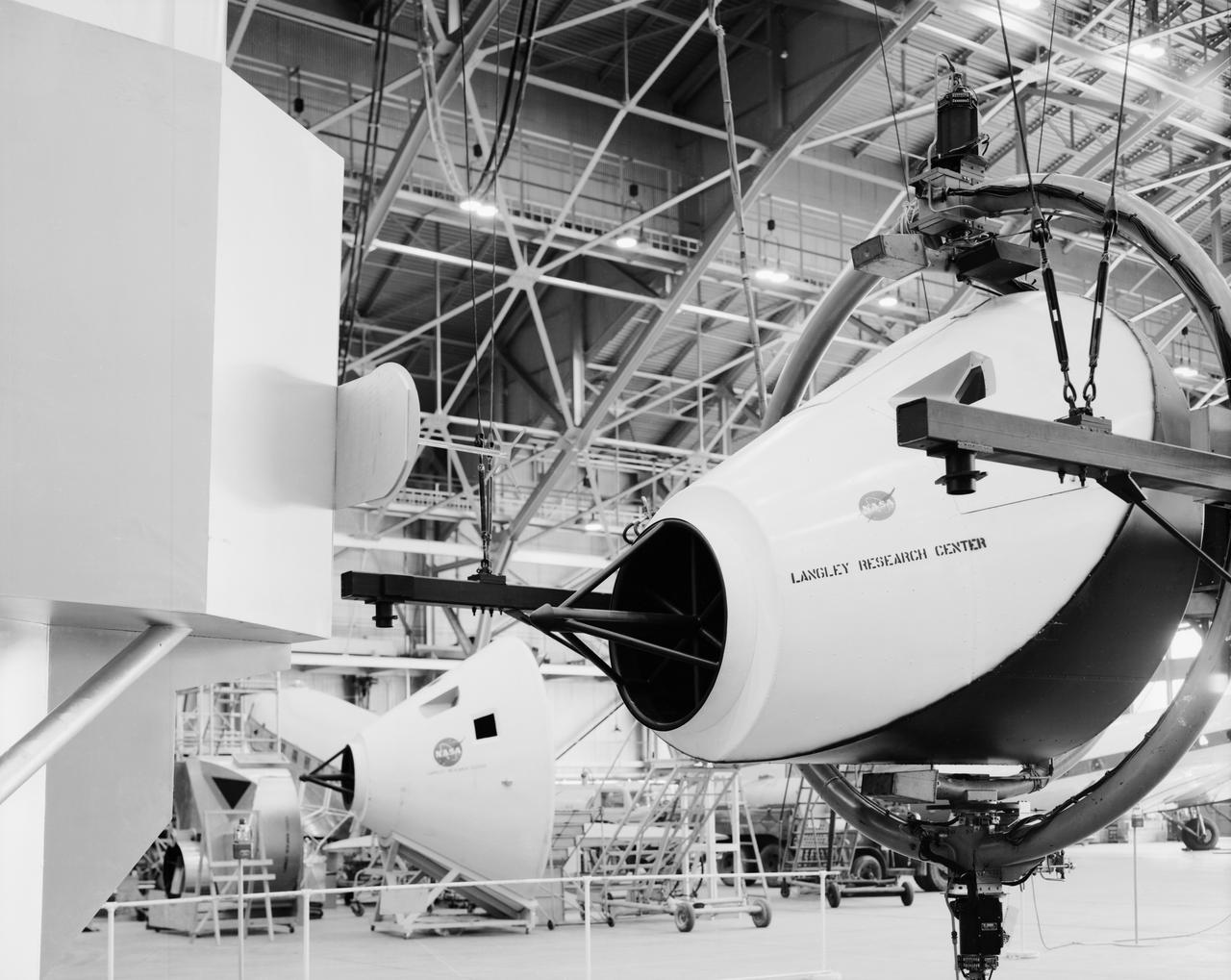
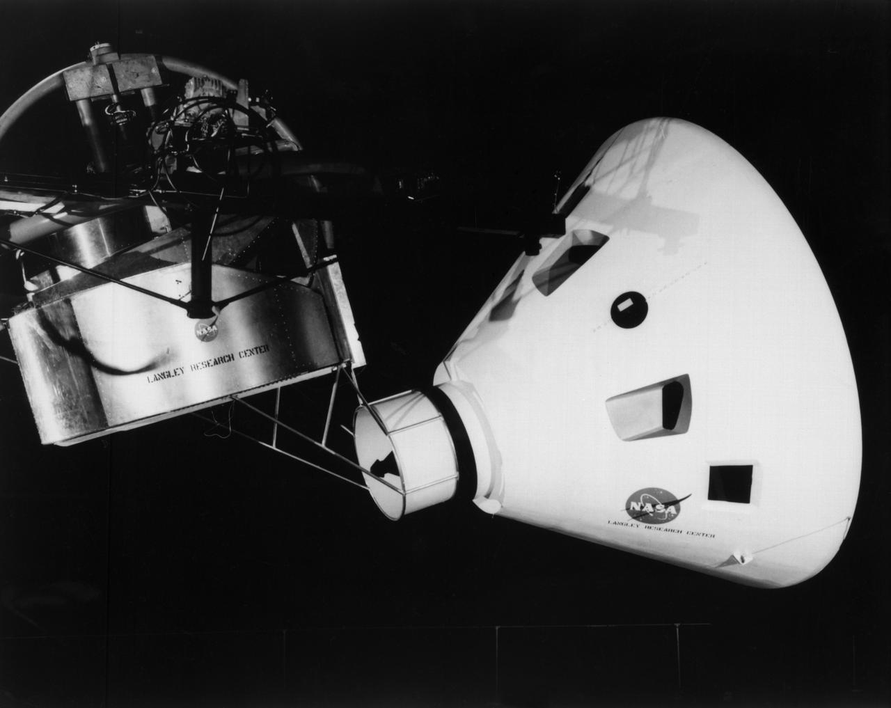
Originally the Rendezvous was used by the astronauts preparing for Gemini missions. The Rendezvous Docking Simulator was then modified and used to develop docking techniques for the Apollo program. The pilot is shown maneuvering the LEM into position for docking with a full-scale Apollo Command Module. From A.W. Vogeley, Piloted Space-Flight Simulation at Langley Research Center, Paper presented at the American Society of Mechanical Engineers, 1966 Winter Meeting, New York, NY, November 27 - December 1, 1966. The Rendezvous Docking Simulator and also the Lunar Landing Research Facility are both rather large moving-base simulators. It should be noted, however, that neither was built primarily because of its motion characteristics. The main reason they were built was to provide a realistic visual scene. A secondary reason was that they would provide correct angular motion cues (important in control of vehicle short-period motions) even though the linear acceleration cues would be incorrect. Apollo Rendezvous Docking Simulator: Langley s Rendezvous Docking Simulator was developed by NASA scientists to study the complex task of docking the Lunar Excursion Module with the Command Module in Lunar orbit.
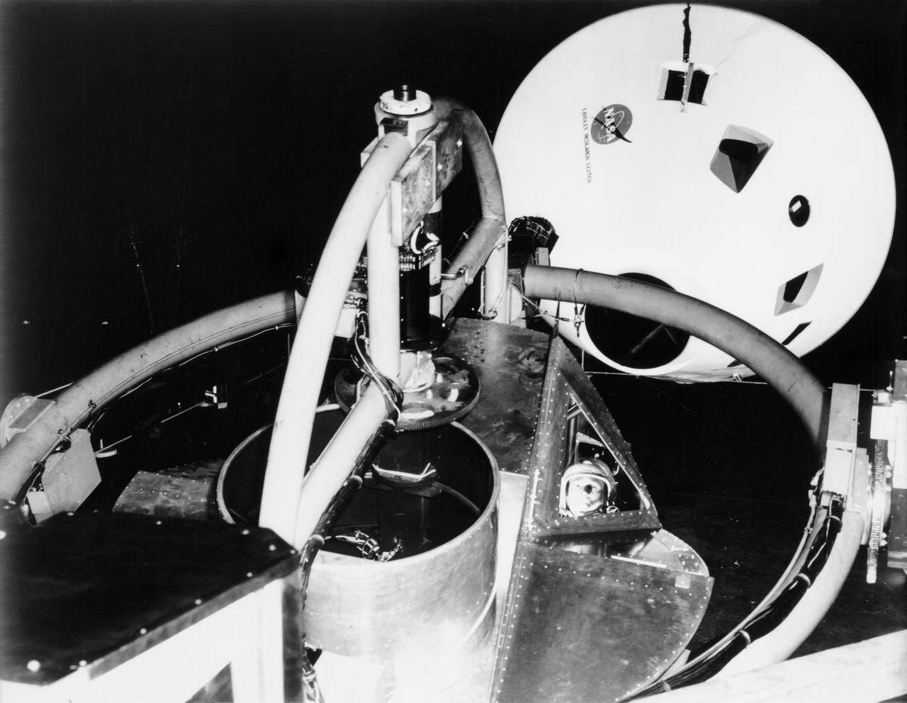
Originally the Rendezvous was used by the astronauts preparing for Gemini missions. The Rendezvous Docking Simulator was then modified and used to develop docking techniques for the Apollo program. "The LEM pilot's compartment, with overhead window and the docking ring (idealized since the pilot cannot see it during the maneuvers), is shown docked with the full-scale Apollo Command Module." A.W. Vogeley described the simulator as follows: "The Rendezvous Docking Simulator and also the Lunar Landing Research Facility are both rather large moving-base simulators. It should be noted, however, that neither was built primarily because of its motion characteristics. The main reason they were built was to provide a realistic visual scene. A secondary reason was that they would provide correct angular motion cues (important in control of vehicle short-period motions) even though the linear acceleration cues would be incorrect." -- Published in A.W. Vogeley, "Piloted Space-Flight Simulation at Langley Research Center," Paper presented at the American Society of Mechanical Engineers, 1966 Winter Meeting, New York, NY, November 27 - December 1, 1966;
Originally the Rendezvous was used by the astronauts preparing for Gemini missions. The Rendezvous Docking Simulator was then modified and used to develop docking techniques for the Apollo program. "The LEM pilot's compartment, with overhead window and the docking ring (idealized since the pilot cannot see it during the maneuvers), is shown docked with the full-scale Apollo Command Module." A.W. Vogeley described the simulator as follows: "The Rendezvous Docking Simulator and also the Lunar Landing Research Facility are both rather large moving-base simulators. It should be noted, however, that neither was built primarily because of its motion characteristics. The main reason they were built was to provide a realistic visual scene. A secondary reason was that they would provide correct angular motion cues (important in control of vehicle short-period motions) even though the linear acceleration cues would be incorrect." -- Published in A.W. Vogeley, "Piloted Space-Flight Simulation at Langley Research Center," Paper presented at the American Society of Mechanical Engineers, 1966 Winter Meeting, New York, NY, November 27 - December 1, 1966;
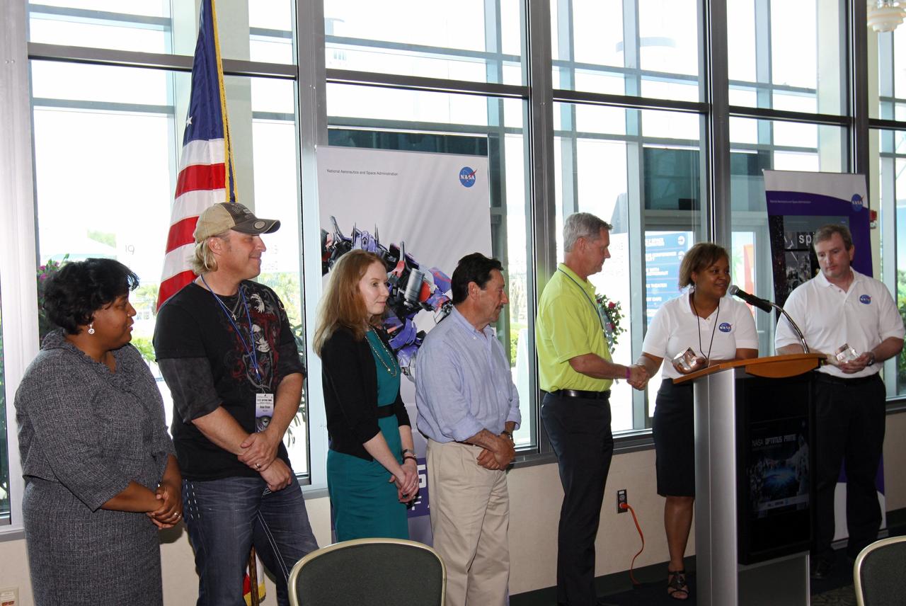
CAPE CANAVERAL, Fla. - In the Debus Conference Center of the Kennedy Space Center Visitor Complex, winners of the NASA OPTIMUS PRIME Spinoff Video Contest receive awards from Joyce Ward, the United States Patent and Trademark Office's education coordinator/administrator, left Ansel Brown, country music singer and song writer of "When You Fly" Sarah Carroll, brand manager of TRANSFORMERS for Hasbro Inc. Peter Cullen, the voice of OPTIMUS PRIME from the "Transformers" franchise Matt Schatzle, executive director of the American Society of Mechanical Engineers Foundation Nona Cheeks, chief of the Technology Commercialization Office at NASA's Goddard Space Flight Center in Greenbelt, Md. and Darryl Mitchell, NASA's project manager for the video contest. The contest challenged students in grades three through 12 to study NASA spinoff technologies and produce short, creative videos promoting their favorites. Goddard's Innovative Partnerships Office designed the contest to help students see the benefits of NASA technology here on Earth. NASA collaborated with Hasbro in using the OPTIMUS PRIME character. Photo credit: NASA/Jim Grossmann
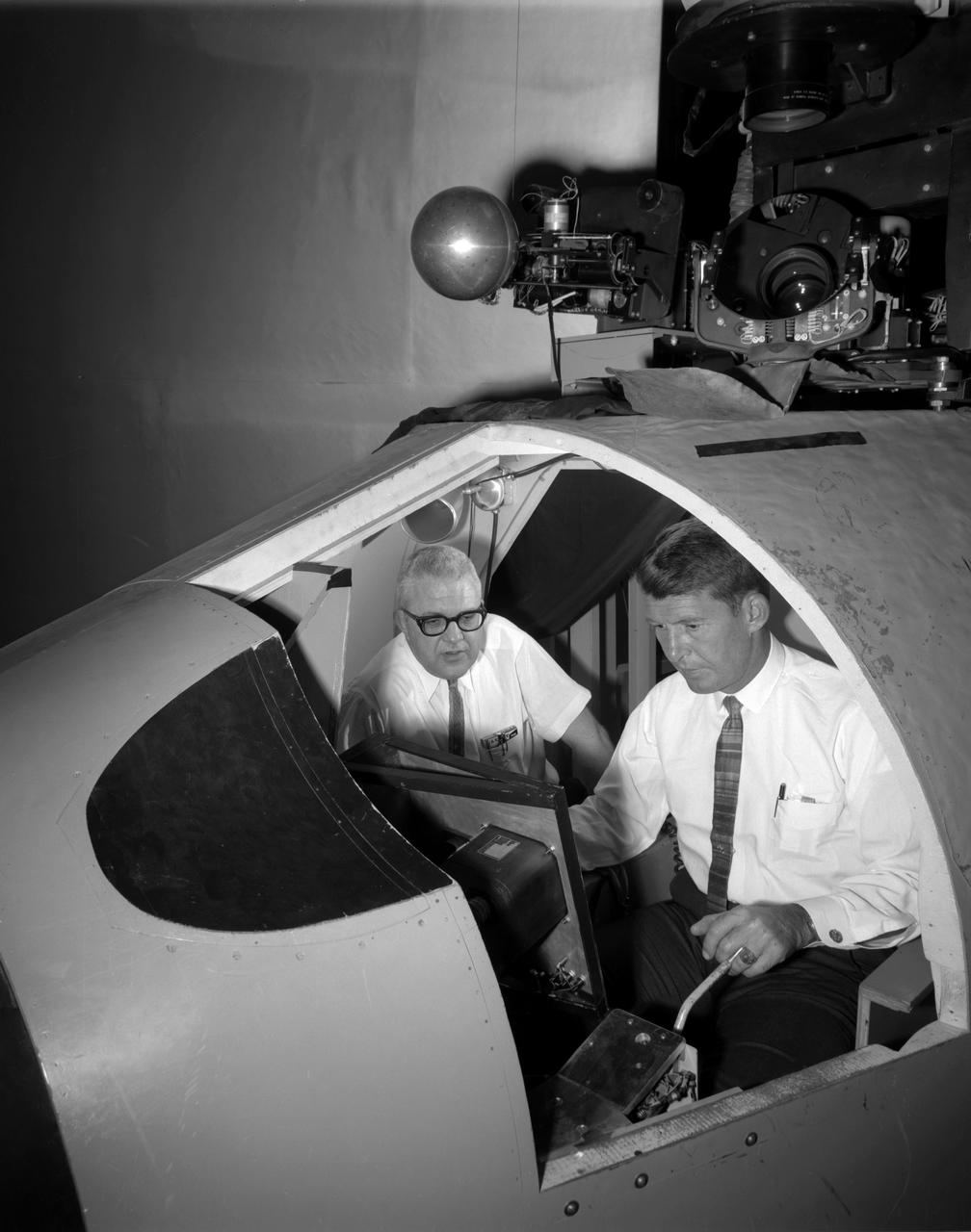
![Astronaut James Lovell at the controls of the Visual Docking Simulator. From A.W. Vogeley, "Piloted Space-Flight Simulation at Langley Research Center," Paper presented at the American Society of Mechanical Engineers 1966 Winter Meeting, New York, NY, November 27-December 1, 1966. "This facility was [later known as the Visual-Optical Simulator.] It presents to the pilot an out-the-window view of his target in correct 6 degrees of freedom motion. The scene is obtained by a television camera pick-up viewing a small-scale gimbaled model of the target." "For docking studies, the docking target picture was projected onto the surface of a 20-foot-diameter sphere and the pilot could, effectively, maneuver into contract. this facility was used in a comparison study with the Rendezvous Docking Simulator - one of the few comparison experiments in which conditions were carefully controlled and a reasonable sample of pilots used. All pilots preferred the more realistic RDS visual scene. The pilots generally liked the RDS angular motion cues although some objected to the false gravity cues that these motions introduced. Training time was shorter on the RDS, but final performance on both simulators was essentially equal. " "For station-keeping studies, since close approach is not required, the target was presented to the pilot through a virtual-image system which projects his view to infinity, providing a more realistic effect. In addition to the target, the system also projects a star and horizon background. "](https://images-assets.nasa.gov/image/LRC-1963-B701_P-09093/LRC-1963-B701_P-09093~medium.jpg)
Astronaut James Lovell at the controls of the Visual Docking Simulator. From A.W. Vogeley, "Piloted Space-Flight Simulation at Langley Research Center," Paper presented at the American Society of Mechanical Engineers 1966 Winter Meeting, New York, NY, November 27-December 1, 1966. "This facility was [later known as the Visual-Optical Simulator.] It presents to the pilot an out-the-window view of his target in correct 6 degrees of freedom motion. The scene is obtained by a television camera pick-up viewing a small-scale gimbaled model of the target." "For docking studies, the docking target picture was projected onto the surface of a 20-foot-diameter sphere and the pilot could, effectively, maneuver into contract. this facility was used in a comparison study with the Rendezvous Docking Simulator - one of the few comparison experiments in which conditions were carefully controlled and a reasonable sample of pilots used. All pilots preferred the more realistic RDS visual scene. The pilots generally liked the RDS angular motion cues although some objected to the false gravity cues that these motions introduced. Training time was shorter on the RDS, but final performance on both simulators was essentially equal. " "For station-keeping studies, since close approach is not required, the target was presented to the pilot through a virtual-image system which projects his view to infinity, providing a more realistic effect. In addition to the target, the system also projects a star and horizon background. "
Walter (Wally) M. Schirra in Visual Docking Simulator From A.W. Vogeley, "Piloted Space-Flight Simulation at Langley Research Center," Paper presented at the American Society of Mechanical Engineers 1966 Winter Meeting, New York, NY, November 27-December 1, 1966. "This facility was [later known as the Visual-Optical Simulator. It presents to the pilot an out-the-window view of his target in correct 6 degrees of freedom motion. The scene is obtained by a television camera pick-up viewing a small-scale gimbaled model of the target. "For docking studies, the docking target picture was projected onto the surface of a 20-foot-diameter sphere and the pilot could, effectively, maneuver into contract. this facility was used in a comparison study with the Rendezvous Docking Simulator - one of the few comparison experiments in which conditions were carefully controlled and a reasonable sample of pilots used. All pilots preferred the more realistic RDS visual scene. The pilots generally liked the RDS angular motion cues although some objected to the false gravity cues that these motions introduced. Training time was shorter on the RDS, but final performance on both simulators was essentially equal. " "For station-keeping studies, since close approach is not required, the target was presented to the pilot through a virtual-image system which projects his view to infinity, providing a more realistic effect. In addition to the target, the system also projects a star and horizon background. "
![Astronaut Virgil "Gus" Grissom at the controls of the Visual Docking Simulator. From A.W. Vogeley, "Piloted Space-Flight Simulation at Langley Research Center," Paper presented at the American Society of Mechanical Engineers 1966 Winter Meeting, New York, NY, November 27-December 1, 1966. "This facility was [later known as the Visual-Optical Simulator.] It presents to the pilot an out-the-window view of his target in correct 6 degrees of freedom motion. The scene is obtained by a television camera pick-up viewing a small-scale gimbaled model of the target." "For docking studies, the docking target picture was projected onto the surface of a 20-foot-diameter sphere and the pilot could, effectively, maneuver into contract. this facility was used in a comparison study with the Rendezvous Docking Simulator - one of the few comparison experiments in which conditions were carefully controlled and a reasonable sample of pilots used. All pilots preferred the more realistic RDS visual scene. The pilots generally liked the RDS angular motion cues although some objected to the false gravity cues that these motions introduced. Training time was shorter on the RDS, but final performance on both simulators was essentially equal. " "For station-keeping studies, since close approach is not required, the target was presented to the pilot through a virtual-image system which projects his view to infinity, providing a more realistic effect. In addition to the target, the system also projects a star and horizon background. "](https://images-assets.nasa.gov/image/LRC-1963-B701_P-01515/LRC-1963-B701_P-01515~medium.jpg)
Astronaut Virgil "Gus" Grissom at the controls of the Visual Docking Simulator. From A.W. Vogeley, "Piloted Space-Flight Simulation at Langley Research Center," Paper presented at the American Society of Mechanical Engineers 1966 Winter Meeting, New York, NY, November 27-December 1, 1966. "This facility was [later known as the Visual-Optical Simulator.] It presents to the pilot an out-the-window view of his target in correct 6 degrees of freedom motion. The scene is obtained by a television camera pick-up viewing a small-scale gimbaled model of the target." "For docking studies, the docking target picture was projected onto the surface of a 20-foot-diameter sphere and the pilot could, effectively, maneuver into contract. this facility was used in a comparison study with the Rendezvous Docking Simulator - one of the few comparison experiments in which conditions were carefully controlled and a reasonable sample of pilots used. All pilots preferred the more realistic RDS visual scene. The pilots generally liked the RDS angular motion cues although some objected to the false gravity cues that these motions introduced. Training time was shorter on the RDS, but final performance on both simulators was essentially equal. " "For station-keeping studies, since close approach is not required, the target was presented to the pilot through a virtual-image system which projects his view to infinity, providing a more realistic effect. In addition to the target, the system also projects a star and horizon background. "
![Astronaut Virgil "Gus" Grissom at the controls of the Visual Docking Simulator. From A.W. Vogeley, "Piloted Space-Flight Simulation at Langley Research Center," Paper presented at the American Society of Mechanical Engineers 1966 Winter Meeting, New York, NY, November 27-December 1, 1966. "This facility was [later known as the Visual-Optical Simulator.] It presents to the pilot an out-the-window view of his target in correct 6 degrees of freedom motion. The scene is obtained by a television camera pick-up viewing a small-scale gimbaled model of the target." "For docking studies, the docking target picture was projected onto the surface of a 20-foot-diameter sphere and the pilot could, effectively, maneuver into contract. this facility was used in a comparison study with the Rendezvous Docking Simulator - one of the few comparison experiments in which conditions were carefully controlled and a reasonable sample of pilots used. All pilots preferred the more realistic RDS visual scene. The pilots generally liked the RDS angular motion cues although some objected to the false gravity cues that these motions introduced. Training time was shorter on the RDS, but final performance on both simulators was essentially equal. " "For station-keeping studies, since close approach is not required, the target was presented to the pilot through a virtual-image system which projects his view to infinity, providing a more realistic effect. In addition to the target, the system also projects a star and horizon background. "](https://images-assets.nasa.gov/image/LRC-1963-B701_P-01516/LRC-1963-B701_P-01516~medium.jpg)
Astronaut Virgil "Gus" Grissom at the controls of the Visual Docking Simulator. From A.W. Vogeley, "Piloted Space-Flight Simulation at Langley Research Center," Paper presented at the American Society of Mechanical Engineers 1966 Winter Meeting, New York, NY, November 27-December 1, 1966. "This facility was [later known as the Visual-Optical Simulator.] It presents to the pilot an out-the-window view of his target in correct 6 degrees of freedom motion. The scene is obtained by a television camera pick-up viewing a small-scale gimbaled model of the target." "For docking studies, the docking target picture was projected onto the surface of a 20-foot-diameter sphere and the pilot could, effectively, maneuver into contract. this facility was used in a comparison study with the Rendezvous Docking Simulator - one of the few comparison experiments in which conditions were carefully controlled and a reasonable sample of pilots used. All pilots preferred the more realistic RDS visual scene. The pilots generally liked the RDS angular motion cues although some objected to the false gravity cues that these motions introduced. Training time was shorter on the RDS, but final performance on both simulators was essentially equal. " "For station-keeping studies, since close approach is not required, the target was presented to the pilot through a virtual-image system which projects his view to infinity, providing a more realistic effect. In addition to the target, the system also projects a star and horizon background. "
![Astronaut Frank Borman at the controls of the Visual Docking Simulator. From A.W. Vogeley, "Piloted Space-Flight Simulation at Langley Research Center," Paper presented at the American Society of Mechanical Engineers 1966 Winter Meeting, New York, NY, November 27-December 1, 1966. "This facility was [later known as the Visual-Optical Simulator.] It presents to the pilot an out-the-window view of his target in correct 6 degrees of freedom motion. The scene is obtained by a television camera pick-up viewing a small-scale gimbaled model of the target." "For docking studies, the docking target picture was projected onto the surface of a 20-foot-diameter sphere and the pilot could, effectively, maneuver into contract. this facility was used in a comparison study with the Rendezvous Docking Simulator - one of the few comparison experiments in which conditions were carefully controlled and a reasonable sample of pilots used. All pilots preferred the more realistic RDS visual scene. The pilots generally liked the RDS angular motion cues although some objected to the false gravity cues that these motions introduced. Training time was shorter on the RDS, but final performance on both simulators was essentially equal. " "For station-keeping studies, since close approach is not required, the target was presented to the pilot through a virtual-image system which projects his view to infinity, providing a more realistic effect. In addition to the target, the system also projects a star and horizon background. "](https://images-assets.nasa.gov/image/LRC-1963-B701_P-09368/LRC-1963-B701_P-09368~medium.jpg)
Astronaut Frank Borman at the controls of the Visual Docking Simulator. From A.W. Vogeley, "Piloted Space-Flight Simulation at Langley Research Center," Paper presented at the American Society of Mechanical Engineers 1966 Winter Meeting, New York, NY, November 27-December 1, 1966. "This facility was [later known as the Visual-Optical Simulator.] It presents to the pilot an out-the-window view of his target in correct 6 degrees of freedom motion. The scene is obtained by a television camera pick-up viewing a small-scale gimbaled model of the target." "For docking studies, the docking target picture was projected onto the surface of a 20-foot-diameter sphere and the pilot could, effectively, maneuver into contract. this facility was used in a comparison study with the Rendezvous Docking Simulator - one of the few comparison experiments in which conditions were carefully controlled and a reasonable sample of pilots used. All pilots preferred the more realistic RDS visual scene. The pilots generally liked the RDS angular motion cues although some objected to the false gravity cues that these motions introduced. Training time was shorter on the RDS, but final performance on both simulators was essentially equal. " "For station-keeping studies, since close approach is not required, the target was presented to the pilot through a virtual-image system which projects his view to infinity, providing a more realistic effect. In addition to the target, the system also projects a star and horizon background. "
![Astronaut Charles Conrad at the controls of the Visual Docking Simulator. From A.W. Vogeley, "Piloted Space-Flight Simulation at Langley Research Center," paper presented at the American Society of Mechanical Engineers 1966 Winter Meeting, New York, NY, November 27-December 1, 1966. "This facility was [later known as the Visual-Optical Simulator.] It presents to the pilot an out-the-window view of his target in correct 6 degrees of freedom motion. The scene is obtained by a television camera pick-up viewing a small-scale gimbaled model of the target." "For docking studies, the docking target picture was projected onto the surface of a 20-foot-diameter sphere and the pilot could, effectively, maneuver into contract. this facility was used in a comparison study with the Rendezvous Docking Simulator - one of the few comparison experiments in which conditions were carefully controlled and a reasonable sample of pilots used. All pilots preferred the more realistic RDS visual scene. The pilots generally liked the RDS angular motion cues although some objected to the false gravity cues that these motions introduced. Training time was shorter on the RDS, but final performance on both simulators was essentially equal. " "For station-keeping studies, since close approach is not required, the target was presented to the pilot through a virtual-image system which projects his view to infinity, providing a more realistic effect. In addition to the target, the system also projects a star and horizon background. "](https://images-assets.nasa.gov/image/LRC-1963-B701_P-09519/LRC-1963-B701_P-09519~medium.jpg)
Astronaut Charles Conrad at the controls of the Visual Docking Simulator. From A.W. Vogeley, "Piloted Space-Flight Simulation at Langley Research Center," paper presented at the American Society of Mechanical Engineers 1966 Winter Meeting, New York, NY, November 27-December 1, 1966. "This facility was [later known as the Visual-Optical Simulator.] It presents to the pilot an out-the-window view of his target in correct 6 degrees of freedom motion. The scene is obtained by a television camera pick-up viewing a small-scale gimbaled model of the target." "For docking studies, the docking target picture was projected onto the surface of a 20-foot-diameter sphere and the pilot could, effectively, maneuver into contract. this facility was used in a comparison study with the Rendezvous Docking Simulator - one of the few comparison experiments in which conditions were carefully controlled and a reasonable sample of pilots used. All pilots preferred the more realistic RDS visual scene. The pilots generally liked the RDS angular motion cues although some objected to the false gravity cues that these motions introduced. Training time was shorter on the RDS, but final performance on both simulators was essentially equal. " "For station-keeping studies, since close approach is not required, the target was presented to the pilot through a virtual-image system which projects his view to infinity, providing a more realistic effect. In addition to the target, the system also projects a star and horizon background. "
![Astronaut James Lovell at the controls of the Visual Docking Simulator. From A.W. Vogeley, "Piloted Space-Flight Simulation at Langley Research Center," Paper presented at the American Society of Mechanical Engineers 1966 Winter Meeting, New York, NY, November 27-December 1, 1966. "This facility was [later known as the Visual-Optical Simulator.] It presents to the pilot an out-the-window view of his target in correct 6 degrees of freedom motion. The scene is obtained by a television camera pick-up viewing a small-scale gimbaled model of the target." "For docking studies, the docking target picture was projected onto the surface of a 20-foot-diameter sphere and the pilot could, effectively, maneuver into contract. this facility was used in a comparison study with the Rendezvous Docking Simulator - one of the few comparison experiments in which conditions were carefully controlled and a reasonable sample of pilots used. All pilots preferred the more realistic RDS visual scene. The pilots generally liked the RDS angular motion cues although some objected to the false gravity cues that these motions introduced. Training time was shorter on the RDS, but final performance on both simulators was essentially equal. " "For station-keeping studies, since close approach is not required, the target was presented to the pilot through a virtual-image system which projects his view to infinity, providing a more realistic effect. In addition to the target, the system also projects a star and horizon background. "](https://images-assets.nasa.gov/image/LRC-1963-B701_P-09094/LRC-1963-B701_P-09094~medium.jpg)
Astronaut James Lovell at the controls of the Visual Docking Simulator. From A.W. Vogeley, "Piloted Space-Flight Simulation at Langley Research Center," Paper presented at the American Society of Mechanical Engineers 1966 Winter Meeting, New York, NY, November 27-December 1, 1966. "This facility was [later known as the Visual-Optical Simulator.] It presents to the pilot an out-the-window view of his target in correct 6 degrees of freedom motion. The scene is obtained by a television camera pick-up viewing a small-scale gimbaled model of the target." "For docking studies, the docking target picture was projected onto the surface of a 20-foot-diameter sphere and the pilot could, effectively, maneuver into contract. this facility was used in a comparison study with the Rendezvous Docking Simulator - one of the few comparison experiments in which conditions were carefully controlled and a reasonable sample of pilots used. All pilots preferred the more realistic RDS visual scene. The pilots generally liked the RDS angular motion cues although some objected to the false gravity cues that these motions introduced. Training time was shorter on the RDS, but final performance on both simulators was essentially equal. " "For station-keeping studies, since close approach is not required, the target was presented to the pilot through a virtual-image system which projects his view to infinity, providing a more realistic effect. In addition to the target, the system also projects a star and horizon background. "
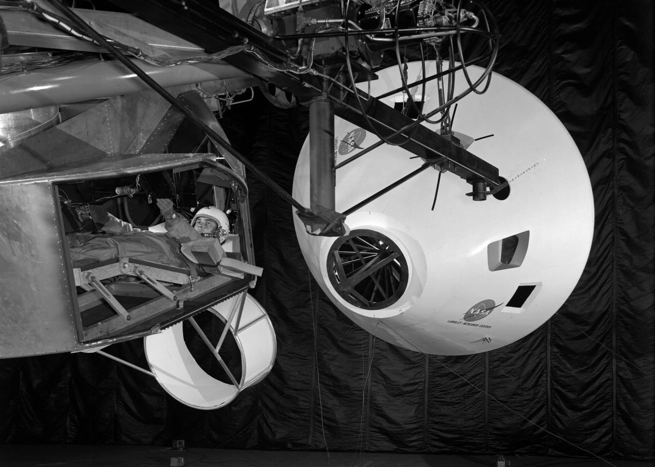
![Test subject wearing jet-shoe apparatus and resting in sling support. The cables are not attached. From A.W. Vogeley, "Piloted Space-Flight Simulation at Langley Research Center," Paper presented at the American Society of Mechanical Engineers, 1966 Winter Meeting, New York, NY, November 27 - December 1, 1966. "As mentioned previously, Langley is conducting in-house and contract studies of extra-vehicular activities wherein zero gravity is simulated by the water-immersion technique. ... Water immersion is a very useful technique where motions are slow. When more rapid motion is required, as in studying one-man propulsion systems, other approaches are required. For these studies Langley has been using the RDS [Rendezvous Docking Simulator] in a manner similar to the LLRF [Lunar Landing Research Facility] technique. The test subjects are suspended in a sling support from a single RDS cable. As they translate about, the RDS tracks them, keeping the cable vertical. The test subjects operate in an effectively zero g environment in the horizontal plane. Tracking was originally done visually using closed-circuit TV, but recently a fast-response servo system using cable angle sensors has provided better operation. Some results of tests where subjects moved about merely by jumping and also where propulsion in the form of simple "jet-shoes" was provided are given in reference 20. Both methods, within limits, appear feasible. Full six-degree-of-freedom equipment for studies of more sophisticated one-man propulsion systems is now being procured. Called OMPRA (One-Man Propulsion Research Apparatus), the device will provide a gimbal system for rotational freedom, a quick response vertical servo for this translational freedom that is not now feasible with the RDS, and a versatile maneuvering unit."](https://images-assets.nasa.gov/image/LRC-1967-B701_P-01373/LRC-1967-B701_P-01373~medium.jpg)
Test subject wearing jet-shoe apparatus and resting in sling support. The cables are not attached. From A.W. Vogeley, "Piloted Space-Flight Simulation at Langley Research Center," Paper presented at the American Society of Mechanical Engineers, 1966 Winter Meeting, New York, NY, November 27 - December 1, 1966. "As mentioned previously, Langley is conducting in-house and contract studies of extra-vehicular activities wherein zero gravity is simulated by the water-immersion technique. ... Water immersion is a very useful technique where motions are slow. When more rapid motion is required, as in studying one-man propulsion systems, other approaches are required. For these studies Langley has been using the RDS [Rendezvous Docking Simulator] in a manner similar to the LLRF [Lunar Landing Research Facility] technique. The test subjects are suspended in a sling support from a single RDS cable. As they translate about, the RDS tracks them, keeping the cable vertical. The test subjects operate in an effectively zero g environment in the horizontal plane. Tracking was originally done visually using closed-circuit TV, but recently a fast-response servo system using cable angle sensors has provided better operation. Some results of tests where subjects moved about merely by jumping and also where propulsion in the form of simple "jet-shoes" was provided are given in reference 20. Both methods, within limits, appear feasible. Full six-degree-of-freedom equipment for studies of more sophisticated one-man propulsion systems is now being procured. Called OMPRA (One-Man Propulsion Research Apparatus), the device will provide a gimbal system for rotational freedom, a quick response vertical servo for this translational freedom that is not now feasible with the RDS, and a versatile maneuvering unit."
![Astronauts Charles Conrad (left) and John W. Young (right) at the controls of the Visual Docking Simulator. From A.W. Vogeley, "Piloted Space-Flight Simulation at Langley Research Center," Paper presented at the American Society of Mechanical Engineers 1966 Winter Meeting, New York, NY, November 27-December 1, 1966. "This facility was [later known as the Visual-Optical Simulator.] It presents to the pilot an out-the-window view of his target in correct 6 degrees of freedom motion. The scene is obtained by a television camera pick-up viewing a small-scale gimbaled model of the target." "For docking studies, the docking target picture was projected onto the surface of a 20-foot-diameter sphere and the pilot could, effectively, maneuver into contract. this facility was used in a comparison study with the Rendezvous Docking Simulator - one of the few comparison experiments in which conditions were carefully controlled and a reasonable sample of pilots used. All pilots preferred the more realistic RDS visual scene. The pilots generally liked the RDS angular motion cues although some objected to the false gravity cues that these motions introduced. Training time was shorter on the RDS, but final performance on both simulators was essentially equal. " "For station-keeping studies, since close approach is not required, the target was presented to the pilot through a virtual-image system which projects his view to infinity, providing a more realistic effect. In addition to the target, the system also projects a star and horizon background. "](https://images-assets.nasa.gov/image/LRC-1963-B701_P-09520/LRC-1963-B701_P-09520~medium.jpg)
Astronauts Charles Conrad (left) and John W. Young (right) at the controls of the Visual Docking Simulator. From A.W. Vogeley, "Piloted Space-Flight Simulation at Langley Research Center," Paper presented at the American Society of Mechanical Engineers 1966 Winter Meeting, New York, NY, November 27-December 1, 1966. "This facility was [later known as the Visual-Optical Simulator.] It presents to the pilot an out-the-window view of his target in correct 6 degrees of freedom motion. The scene is obtained by a television camera pick-up viewing a small-scale gimbaled model of the target." "For docking studies, the docking target picture was projected onto the surface of a 20-foot-diameter sphere and the pilot could, effectively, maneuver into contract. this facility was used in a comparison study with the Rendezvous Docking Simulator - one of the few comparison experiments in which conditions were carefully controlled and a reasonable sample of pilots used. All pilots preferred the more realistic RDS visual scene. The pilots generally liked the RDS angular motion cues although some objected to the false gravity cues that these motions introduced. Training time was shorter on the RDS, but final performance on both simulators was essentially equal. " "For station-keeping studies, since close approach is not required, the target was presented to the pilot through a virtual-image system which projects his view to infinity, providing a more realistic effect. In addition to the target, the system also projects a star and horizon background. "