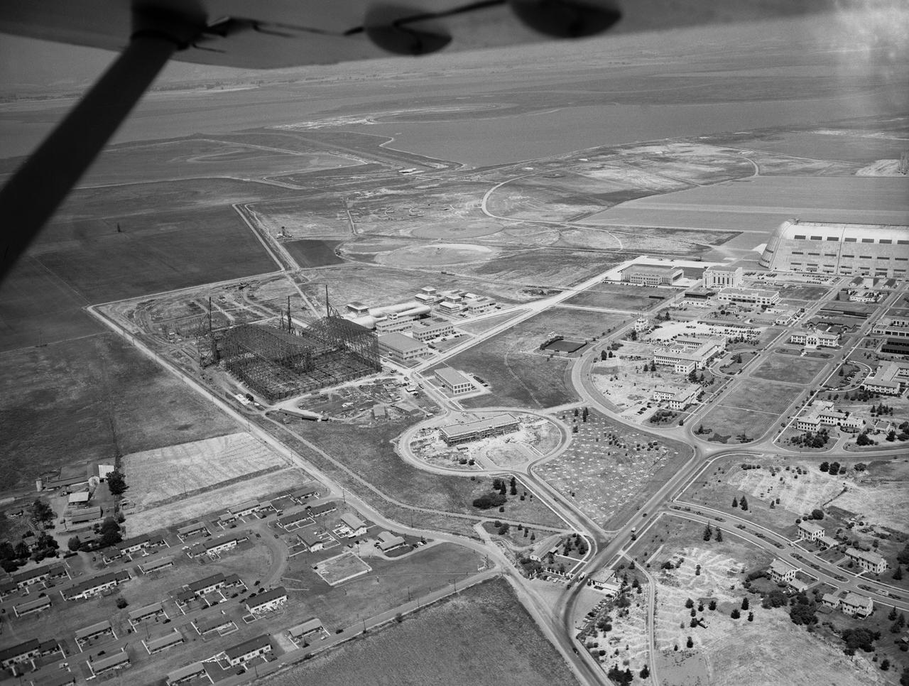
Early aerial of the NASA Ames Aeronautical Laboratory
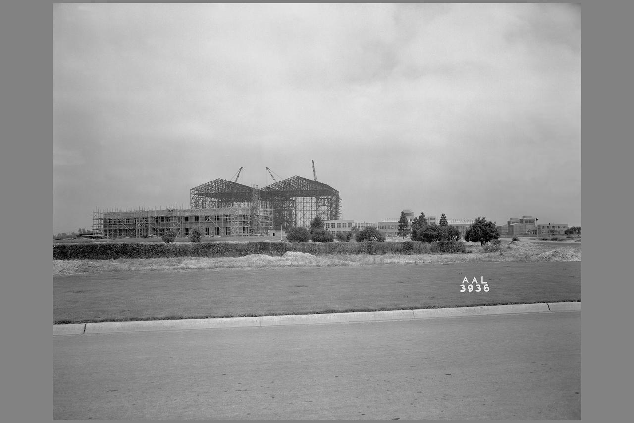
Ames Aeronautical Laboratory skyline from Akron Road
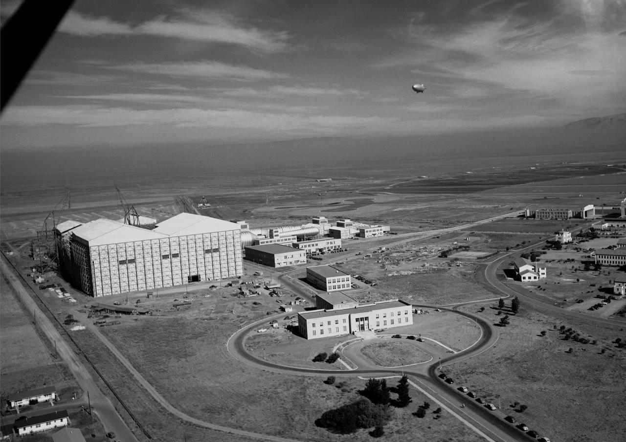
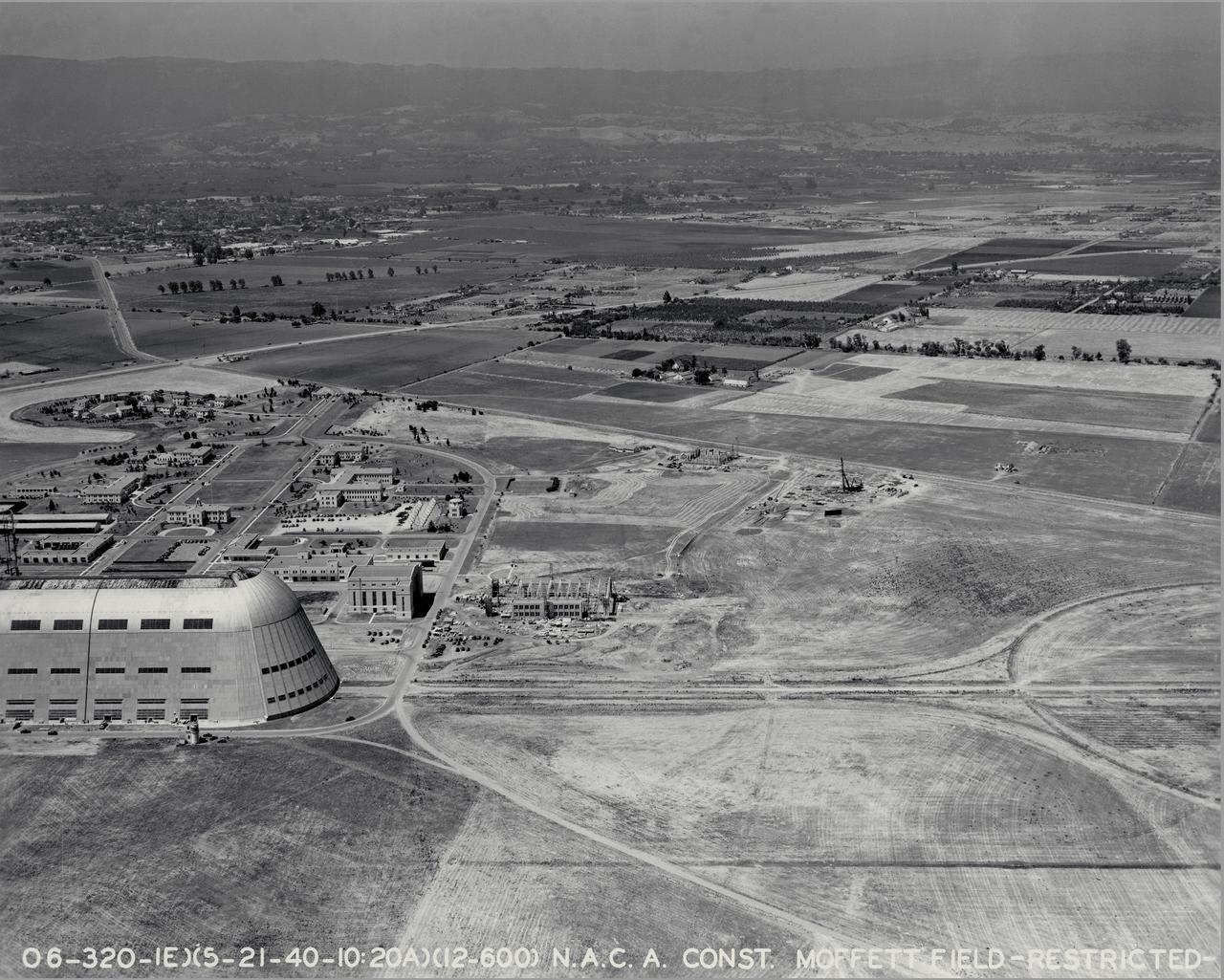
Ames aerial view of Ames Aeronautical Laboratory plot looking northeast with blimp in flight over Moffett Naval airstation.
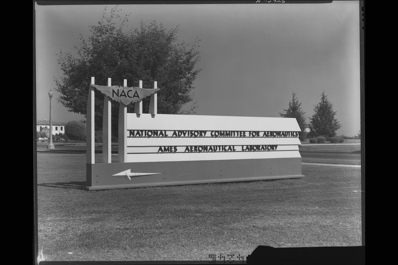
NACA (National Advisory Committee for Aeronautics) sign at entrance to Ames Laboratory
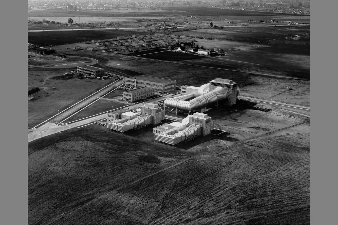
Aerial view of Ames Aeronautical Laboratory, Moffett Field California.
Aerial view of Ames Aeronautical Laboratory (with blimps in flight over Moffett runway)
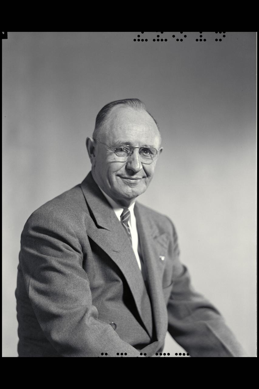
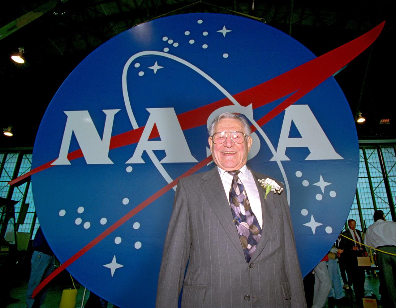
NACA Photographer Portrait: Dr. Smith J. (Smithy) DeFrance, First Director of Ames Research Center 1940 - 1965 (then Ames Aeronautical Laboratory)
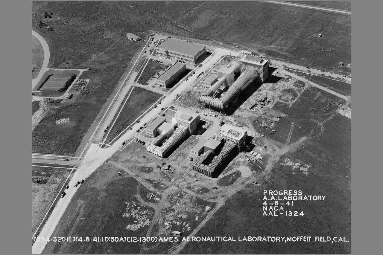
Army Air Photo - General view looking west at Ames Aeronautical Laboratory construction progress
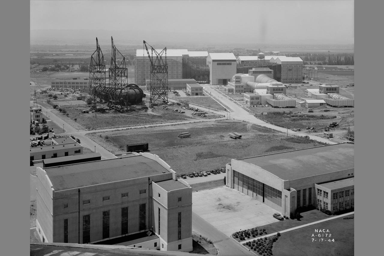
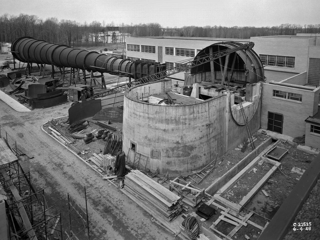
General view of Ames Aeronautical Laboratory taken from Naval airship hangar. Shows construction of the 12ft Pressure Wind Tunnel with large cranes.
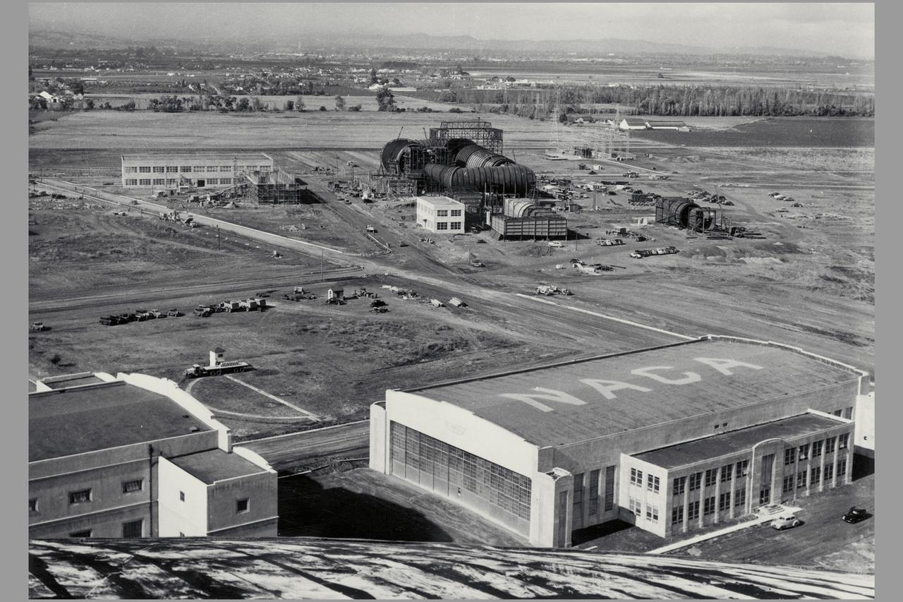
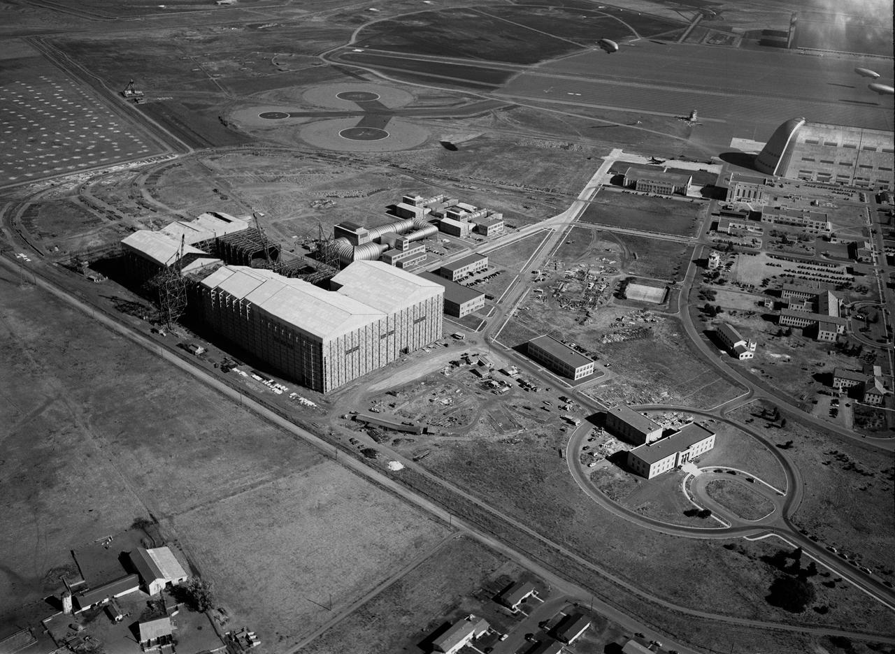
Date: Nov 9, 1940 Aerial view of Ames Aeronautical Laboratory showing Flight Research Lab and Construction of 16ft wind tunnel
Ames Aeronautical Research Laboratory aerial shows original flight research hangar in foreground, the two 7x10ft w.t. the 16ft w.t. and Admin buildings NOTE: printed in NASA Ames Publications: Adventures in Research - SP-4320; Searching the Horizon - SP 4304; 57 Years - Flight Research at AMES - NASA SP-1998-3300
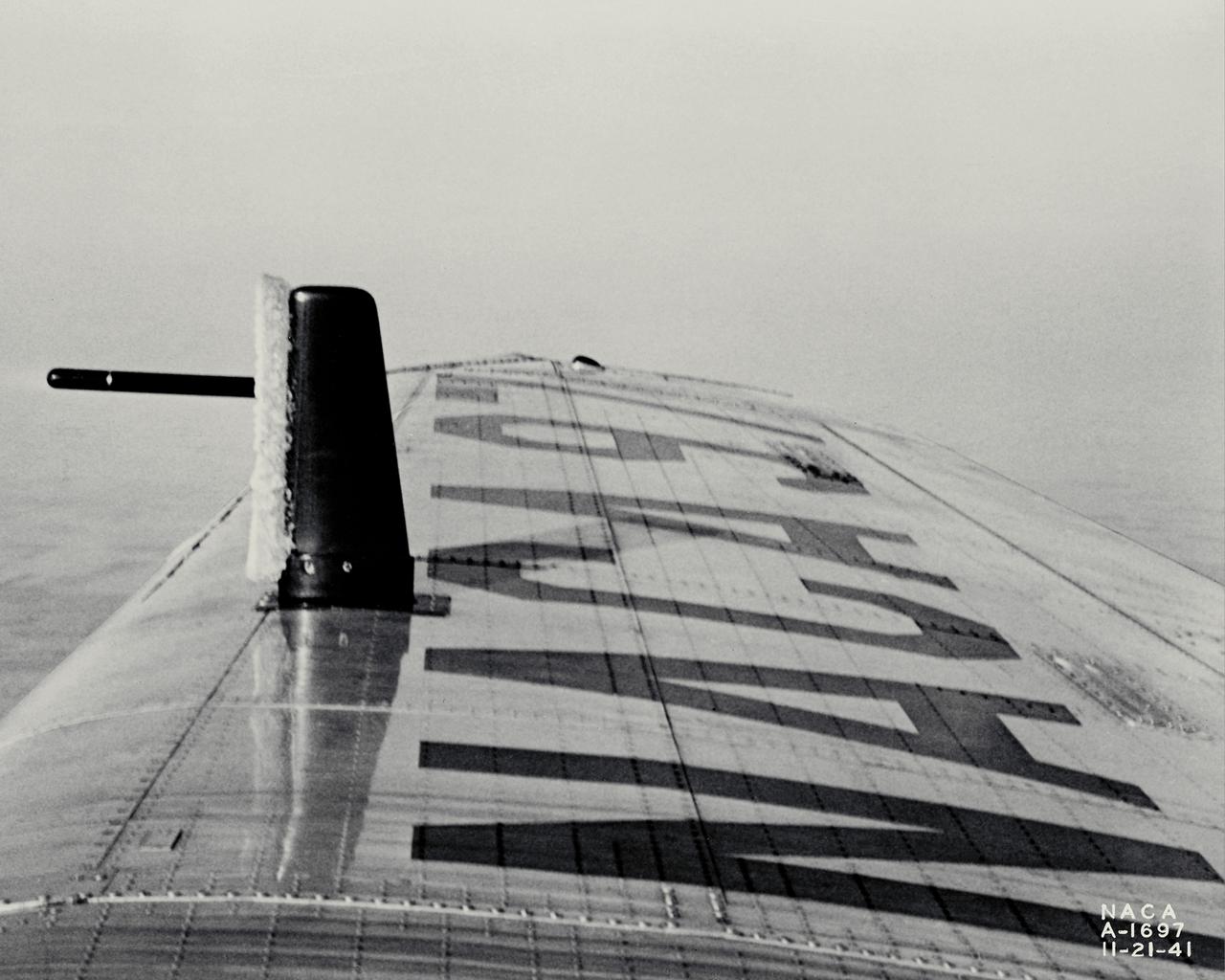
NACA photographer Ice Reearch being conducted at NACA Ames Aeronautical Laboratory on a Lockheed 12-A, NACA 97; test #4, ice on tell-tale strut in flight
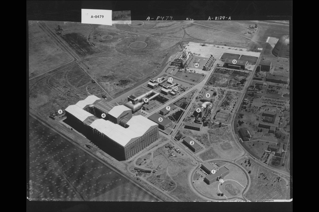
Army Air Photo Ames Aeronautical Laboratory construction progress showing two (2) 7x10ft wind tunnels, the 16ft wind tunnel, Technical and Electrical Services Buildings and the construction shack. (Ref: 0-34)
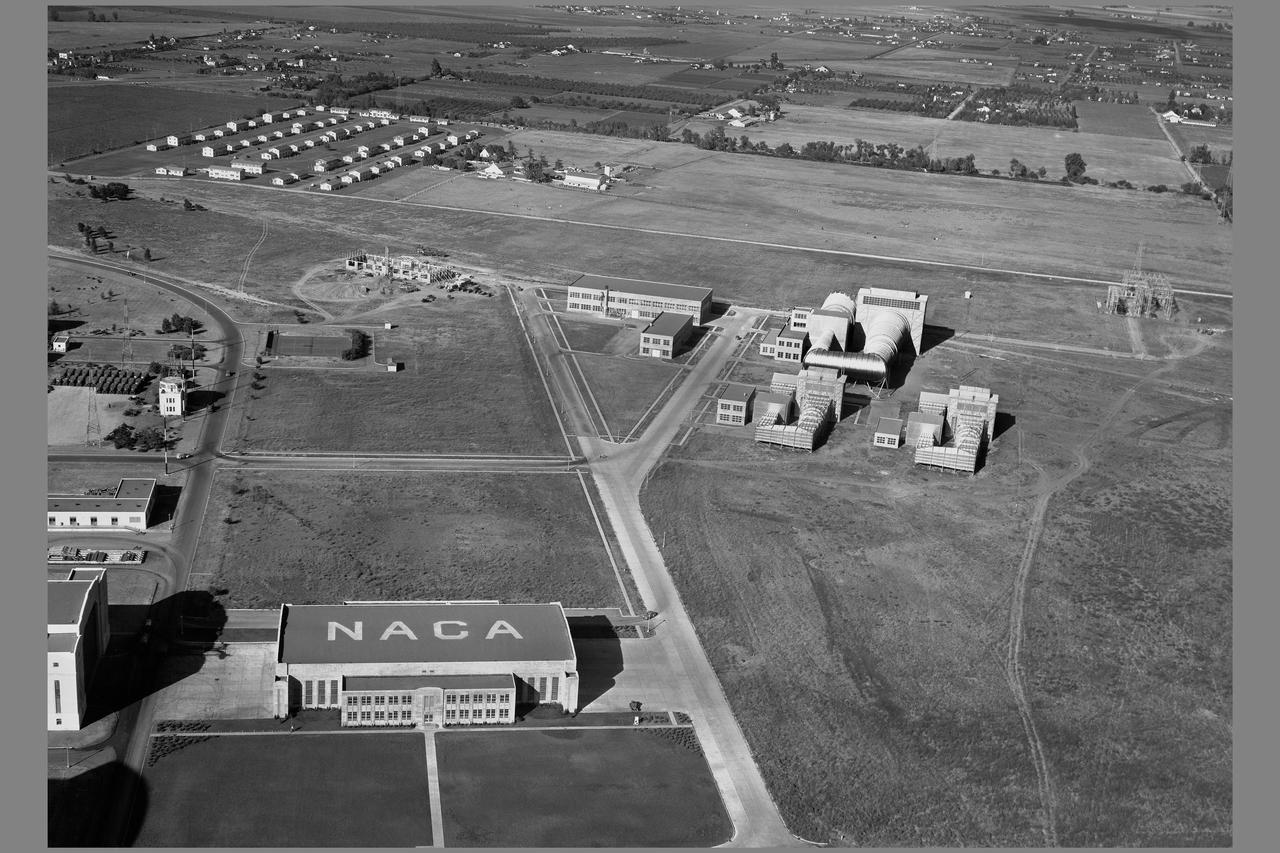
NACA Ames Aeronautical Laboratory aerial; 16ft, 7X10ft#1, 7x10ft#2 wind tunnels, Technical Services Bldg N-220, Utilities later Electrical Services Bldg N-219 and construction on the Science Laboratory, later Engineering Services Bldg N-203
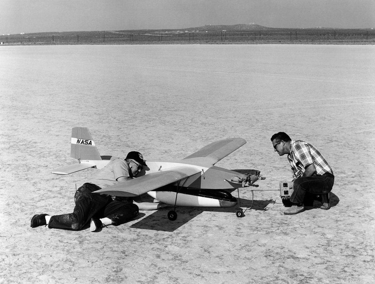
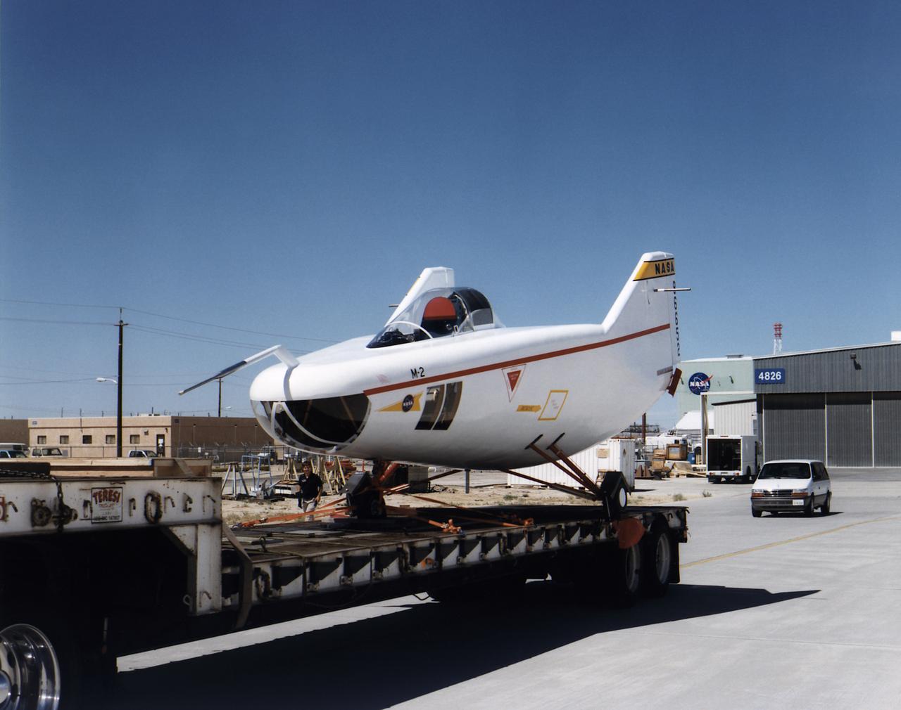
A photo of model airplane builders James B. Newman and Robert L. McDonald preparing for a flight with models of the M2-F2 and a “Mothership”. In 1968 a test flight was made on the Rosamond dry lakebed, Rosamond, California. The original idea of lifting bodies was conceived about 1957 by Dr. Alfred J. Eggers, Jr., then the assistant director for Research and Development Analysis and Planning at the National Advisory Committee for Aeronautics' Ames Aeronautical Laboratory, Moffett Field, California. Nose cone studies led to the design known as the M-2, a modified half-cone, rounded on the bottom and flat on top, with a blunt, rounded nose and twin tail fins. To gather flight data on this configuration, models were found to be an effective method. A special twin-engined, 14-foot model “mothership” was used for carrying the M2-F2 model to altitude and a launch, much as was being done with the B-52 for the full-scale lifting bodies. Jim (on the left) will fly the “mothership” and Bob will take control of the M2-F2 at launch and fly it to a landing on the lakebed.
The M2-F1 Lifting Body is seen here under tow by an unseen C-47 at the NASA Flight Research Center (later redesignated the Dryden Flight Research Center), Edwards, California. The low-cost vehicle was the first piloted lifting body to be test flown. The lifting-body concept originated in the mid-1950s at the National Advisory Committee for Aeronautics' Ames Aeronautical Laboratory, Mountain View California. By February 1962, a series of possible shapes had been developed, and R. Dale Reed was working to gain support for a research vehicle.
The 8- by 6-Foot Supersonic Wind Tunnel at the National Advisory Committee for Aeronautics (NACA) Lewis Flight Propulsion Laboratory was the nation’s largest supersonic facility when it began operation in April 1949. The emergence of new propulsion technologies such as turbojets, ramjets, and rockets during World War II forced the NACA and the aircraft industry to develop new research tools. In late 1945 the NACA began design work for new large supersonic wind tunnels at its three laboratories. The result was the 4- by 4-Foot Supersonic Wind Tunnel at Langley Memorial Aeronautical Laboratory, 6- by 6-foot supersonic wind tunnel at Ames Aeronautical Laboratory, and the largest facility, the 8- by 6-Foot Supersonic Wind Tunnel in Cleveland. The two former tunnels were to study aerodynamics, while the 8- by 6 facility was designed for supersonic propulsion. The 8- by 6-Foot Supersonic Wind Tunnel was used to study propulsion systems, including inlets and exit nozzles, combustion fuel injectors, flame holders, exit nozzles, and controls on ramjet and turbojet engines. Flexible sidewalls alter the tunnel’s nozzle shape to vary the Mach number during operation. A seven-stage axial compressor, driven by three electric motors that yield a total of 87,000 horsepower, generates air speeds from Mach 0.36 to 2.0. A section of the tunnel is seen being erected in this photograph.
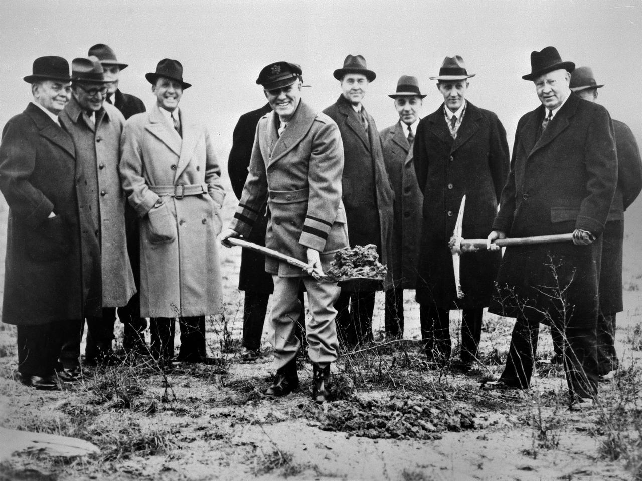
Local politicians and National Advisory Committee for Aeronautics (NACA) officials were on hand for the January 23, 1941 groundbreaking for the NACA’s Aircraft Engine Research Laboratory (AERL). The NACA was established in 1915 to coordinate the nation’s aeronautical research. The committee opened a research laboratory at Langley Field in 1920. By the late 1930s, however, European nations, Germany in particular, were building faster and higher flying aircraft. The NACA decided to expand with a new Ames Aeronautical Laboratory dedicated to high-speed flight and the AERL to handle engine-related research. The NACA examined a number of Midwest locations for its new engine lab before deciding on Cleveland. At the time, Cleveland possessed the nation’s most advanced airport, several key aircraft manufacturing companies, and was home to the National Air Races. Local officials were also able to broker a deal with the power company to discount its electricity rates if the large wind tunnels were operated overnight. The decision was made in October 1940, and the groundbreaking alongside the airport took place on January 23, 1941. From left to right: William Hopkins, John Berry, Ray Sharp, Frederick Crawford, George Brett, Edward Warner, Sydney Kraus, Edward Blythin, and George Lewis
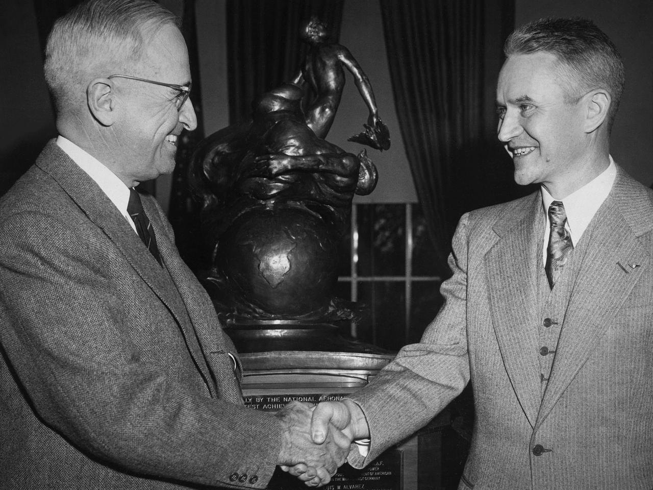
Lewis Rodert, then of the National Advisory Committee for Aeronautics (NACA) Lewis Flight Propulsion Laboratory, receives the Collier Trophy from President Harry Truman for his work in the design and development of an ice prevention system for aircraft. The accumulation of ice on an aircraft had been a critical issue for years. Rodert developed a method of transferring engine heat to the wings and other vulnerable components to prevent ice buildup. Rodert began his icing investigations at Langley Memorial Aeronautical Laboratory in 1936. The NACA ordered a Lockheed 12A aircraft to be built using Rodert’s deicing system. The aircraft successfully flew through icing conditions during the following winter. Soon thereafter the military incorporated the system into a Consolidated B-24D Liberator and several other military aircraft, including a North American XB-25F. Rodert and the NACA icing program transferred to the Lewis lab in Cleveland in 1946. In Cleveland, the focus turned to the study of cloud composition and the causes of icing. Rodert’s role at Lewis diminished over the ensuing years. Rodert was honored in 1947 for his Collier Trophy at ceremonies at Langley, Ames, and then finally Lewis.
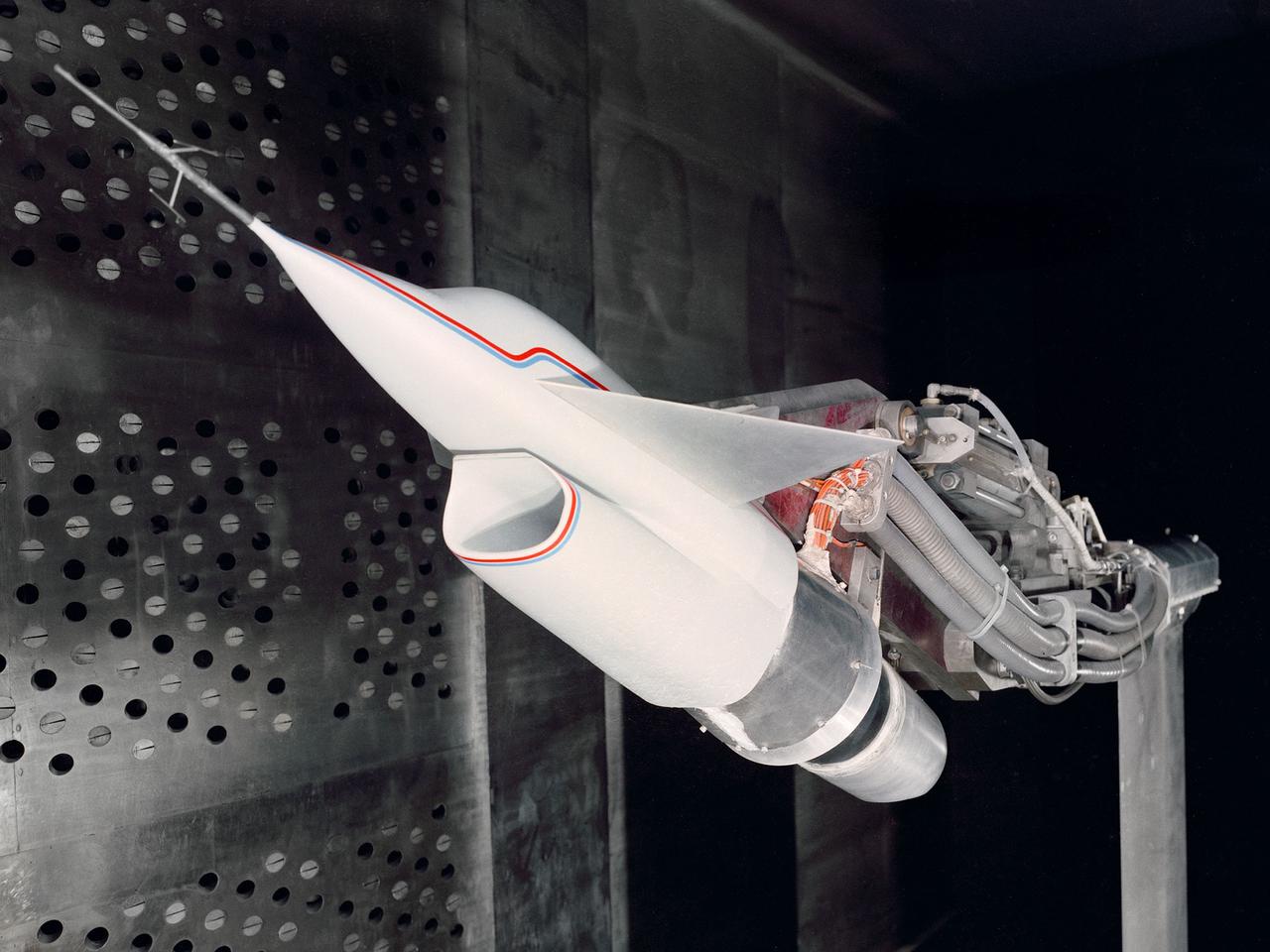
A Highly Maneuverable Aircraft Technology (HiMAT) inlet model installed in the test section of the 8- by 6-Foot Supersonic Wind Tunnel at the National Aeronautics and Space Administration (NASA) Lewis Research Center. Engineers at the Ames Research Center, Dryden Flight Research Center, and Rockwell International designed two pilotless subscale HiMAT vehicles in the mid-1970s to study new design concepts for fighter aircraft in the transonic realm without risking the lives of test pilots. The aircraft used sophisticated technologies such as advanced aerodynamics, composite materials, digital integrated propulsion control, and digital fly-by-wire control systems. In late 1977 NASA Lewis studied the HiMAT’s General Electric J85-21 jet engine in the Propulsion Systems Laboratory. The researchers charted the inlet quality with various combinations anti-distortion screens. HiMAT employed a relatively short and curved inlet compared to actual fighter jets. In the spring of 1979, Larry Smith led an in-depth analysis of the HiMAT inlet in the 8- by 6 tunnel. The researchers installed vortex generators to battle flow separation in the diffuser. The two HiMAT aircraft performed 11 hours of flying over the course of 26 missions from mid-1979 to January 1983 at Dryden and Ames. Although the HiMAT vehicles were considered to be overly complex and expensive, the program yielded a wealth of data that would validate computer-based design tools.
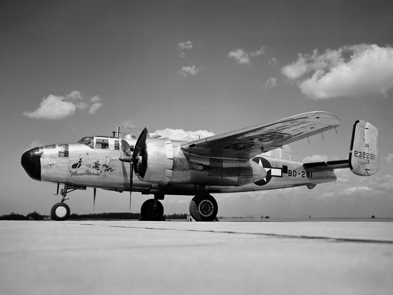
In 1946 the Lewis Flight Propulsion Laboratory became the NACA’s official icing research center. In addition to the Icing Research Tunnel, the lab possessed several aircraft modified for icing work, including a Consolidated B-24M Liberator and a North American XB-25E Mitchell, seen here. The XB-25E’s frequent engine fires allegedly resulted in its “Flamin’ Maimie” nickname. The aircraft’s nose art, visible in this photograph, includes a leather-jacketed mechanic with an extinguisher fleeing a fiery woman. North American developed the B-25 in the mid-1930s as a transport aircraft, but it was hurriedly reconfigured as a medium bomber for World War II. This XB-25E was a single prototype designed in 1942 specifically to test an exhaust gas ice prevention system developed by NACA researcher Lewis Rodert. The system circulated the engines’ hot bleed air to the wings, windshield, and tail. The XB-25E was utilized at the NACA’s Ames Aeronautical Laboratory for two years before being transferred to Cleveland in July 1944. NACA Lewis mechanics modified the aircraft further by installing electrical heating in the front fuselage, propellers, inboard sing, cowls, and antennae. Lewis pilots flew the B-24M and XB-25E into perilous weather conditions all across the country to study both deicing technologies and the physics of ice-producing clouds. These dangerous flights led to advances in weather sensing instruments and flight planning.
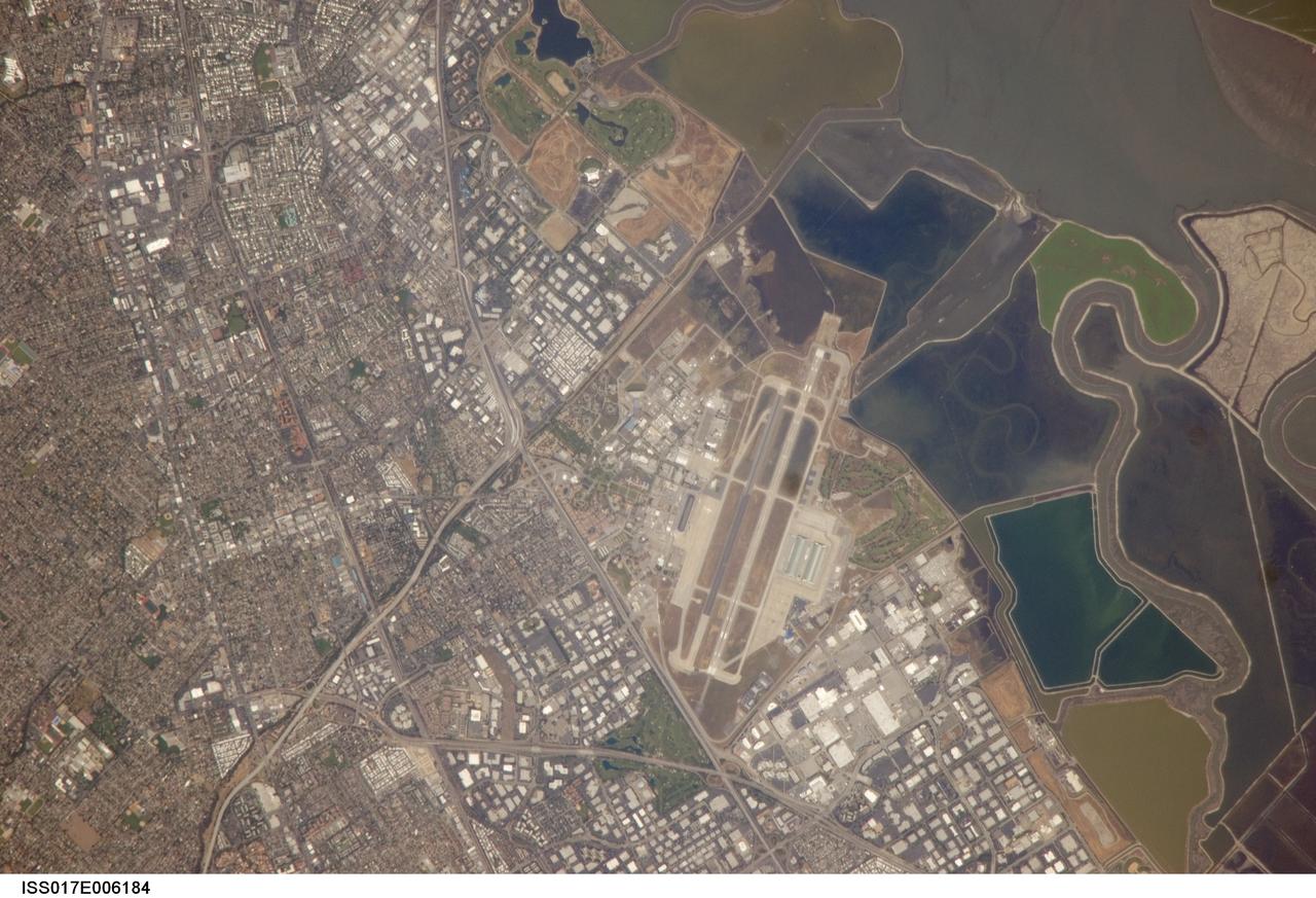
ISS017-E-006184 (3 May 2008) --- NASA Ames Research Center, Moffett Field, CA is featured in this image photographed by an Expedition 17 crewmember on the International Space Station. This view illustrates the diverse built environment surrounding NASA's Ames Research Center, or ARC located at the southernmost end of the San Francisco Bay. Founded in 1939 as an aircraft research laboratory, Ames became a NASA facility in 1958. Its original aircraft research focus was enhanced by the adjacent Moffett Field -- an active Naval Air Station until 1994 and original home of the Navy dirigible U.S.S. Macon. The large hangar for docking the U.S.S. Macon is still present at Moffett Field, and is visible in this image (center). Today, NASA ARC includes the former Naval Air Station, and continues its focus on aeronautics in addition to nanotechnology, information technology, fundamental space biology, biotechnology, thermal protection systems, and human factors research. Land use and land cover in the southern San Francisco Bay area is a diverse mix of industrial, institutional, and residential patterns. Industrial lots -- characterized by lack of green vegetation and large buildings with highly reflective white rooftops -- border NASA ARC to the west, east, and south. The city of Mountain View directly to the south appears as a dense gray-brown network of streets and residential properties with interspersed green parks. The northern boundary of NASA ARC consists of former salt ponds in the process of being returned to tidal wetlands (right). Drainage channels that predate the salt pond levees are visible at right.
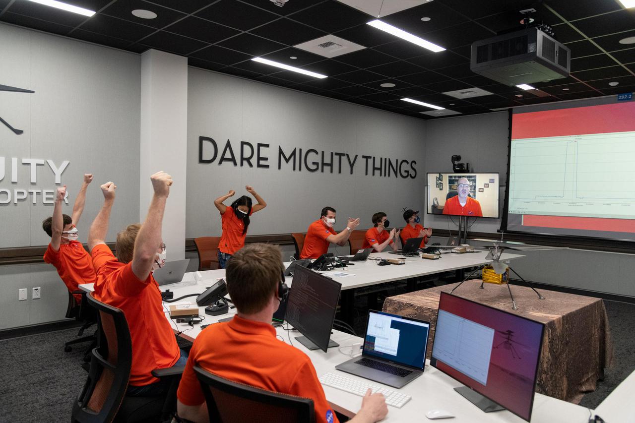
Members of NASA's Ingenuity helicopter team in the Space Flight Operations Facility at NASA's Jet Propulsion Laboratory react to data showing that the helicopter completed its first flight on April 19, 2021. The Ingenuity Mars Helicopter was built by JPL, which also manages this technology demonstration project for NASA Headquarters. It is supported by NASA's Science Mission Directorate, Aeronautics Research Mission Directorate, and Space Technology Mission Directorate. NASA's Ames Research Center and Langley Research Center provided significant flight performance analysis and technical assistance during Ingenuity's development. A key objective for Perseverance's mission on Mars is astrobiology, including the search for signs of ancient microbial life. The rover will characterize the planet's geology and past climate, pave the way for human exploration of the Red Planet, and be the first mission to collect and cache Martian rock and regolith (broken rock and dust). Subsequent NASA missions, in cooperation with ESA (European Space Agency), would send spacecraft to Mars to collect these sealed samples from the surface and return them to Earth for in-depth analysis. The Mars 2020 Perseverance mission is part of NASA's Moon to Mars exploration approach, which includes Artemis missions to the Moon that will help prepare for human exploration of the Red Planet. https://photojournal.jpl.nasa.gov/catalog/PIA24499
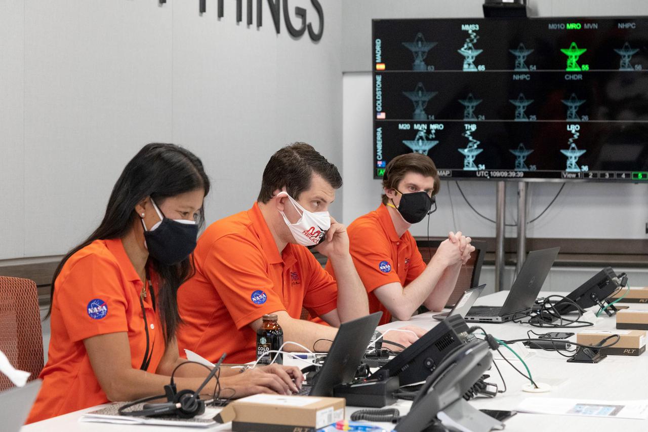
Members of NASA's Ingenuity helicopter team in the Space Flight Operations Facility at NASA's Jet Propulsion Laboratory prepare to receive the data downlink showing whether the helicopter completed its first flight on April 19, 2021. The Ingenuity Mars Helicopter was built by JPL, which also manages this technology demonstration project for NASA Headquarters. It is supported by NASA's Science Mission Directorate, Aeronautics Research Mission Directorate, and Space Technology Mission Directorate. NASA's Ames Research Center and Langley Research Center provided significant flight performance analysis and technical assistance during Ingenuity's development. A key objective for Perseverance's mission on Mars is astrobiology, including the search for signs of ancient microbial life. The rover will characterize the planet's geology and past climate, pave the way for human exploration of the Red Planet, and be the first mission to collect and cache Martian rock and regolith (broken rock and dust). Subsequent NASA missions, in cooperation with ESA (European Space Agency), would send spacecraft to Mars to collect these sealed samples from the surface and return them to Earth for in-depth analysis. The Mars 2020 Perseverance mission is part of NASA's Moon to Mars exploration approach, which includes Artemis missions to the Moon that will help prepare for human exploration of the Red Planet. https://photojournal.jpl.nasa.gov/catalog/PIA24585
In 1949, after graduating from the Cleveland Institute of Art, James “Jim” Modarelli began his career as an artist-designer at the laboratory that would become the NASA Glenn Research Center. When the NACA was approved to be absorbed into the new space agency—NASA, employees were invited to submit designs for the Agency’s logo. Modarelli, who was serving as the Management Services Division Chief at the time, submitted the winning designs. The official NASA seal and the less formal NASA “meatball” insignia (shown here) are among the most recognized emblems in the world. The logos, which include symbols representing the space and aeronautics missions of NASA, became official in 1959. In July 1958, Modarelli participated in a tour at the Ames Unitary Plan Wind Tunnel, where he viewed a model of a radical supersonic airplane designed for flight at Mach 3.0. With a cambered, twisted arrow wing and an upturned nose, the model deeply impressed Modarelli. He later stylized the radical features of the arrow-wing configuration in his evolution of the NASA seal design; the wing would also become an element of the NASA insignia.
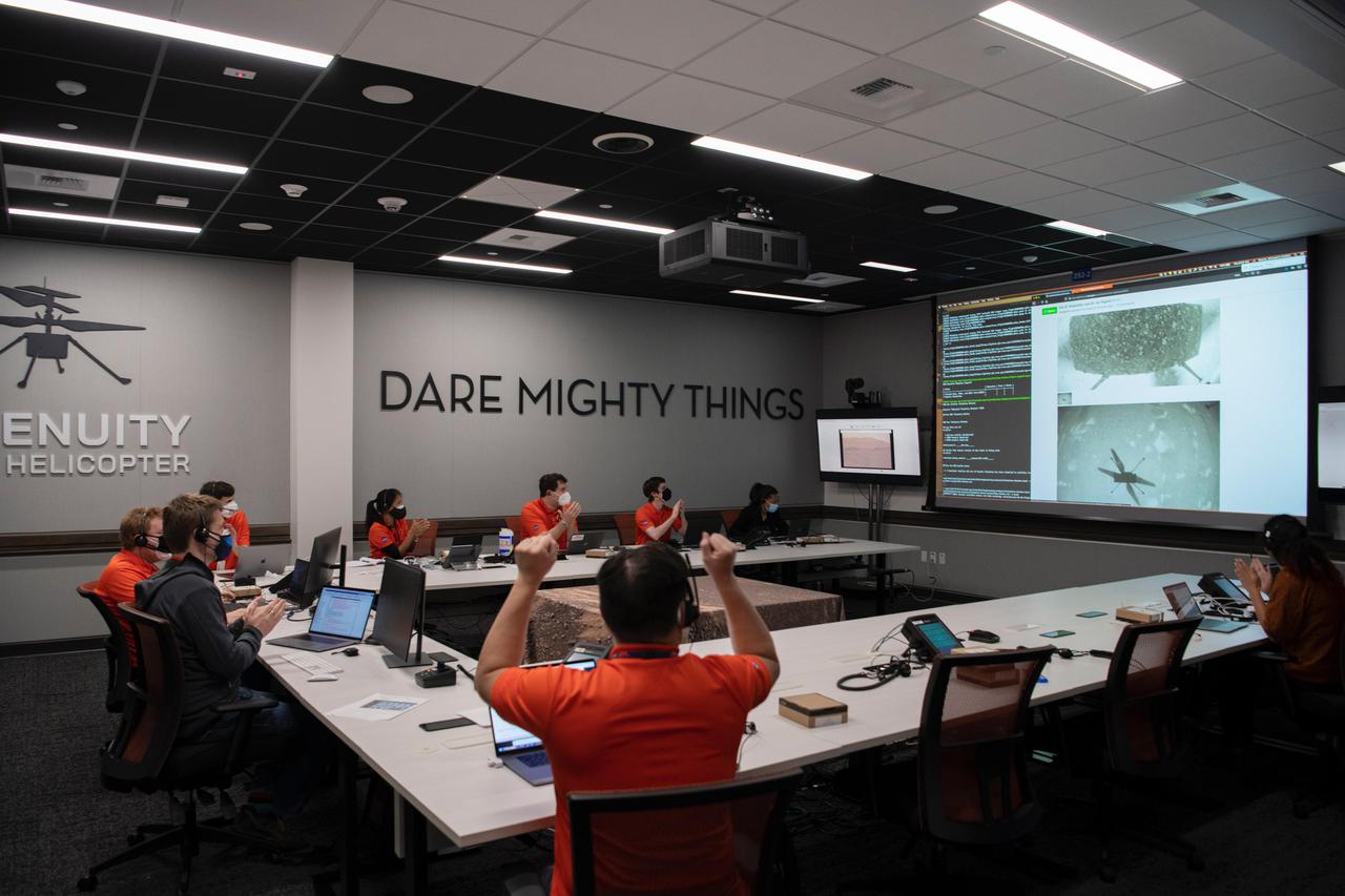
Members of NASA's Ingenuity Mars Helicopter team at the agency's Jet Propulsion Laboratory react to data showing that the helicopter completed its second flight on the Red Planet on April 22, 2021. The Ingenuity Mars Helicopter was built by JPL, which also manages this technology demonstration project for NASA Headquarters. It is supported by NASA's Science Mission Directorate, Aeronautics Research Mission Directorate, and Space Technology Mission Directorate. NASA's Ames Research Center and Langley Research Center provided significant flight performance analysis and technical assistance during Ingenuity's development. A key objective for Perseverance's mission on Mars is astrobiology, including the search for signs of ancient microbial life. The rover will characterize the planet's geology and past climate, pave the way for human exploration of the Red Planet, and be the first mission to collect and cache Martian rock and regolith (broken rock and dust). Subsequent NASA missions, in cooperation with ESA (European Space Agency), would send spacecraft to Mars to collect these sealed samples from the surface and return them to Earth for in-depth analysis. The Mars 2020 Perseverance mission is part of NASA's Moon to Mars exploration approach, which includes Artemis missions to the Moon that will help prepare for human exploration of the Red Planet. https://photojournal.jpl.nasa.gov/catalog/PIA24597

S73-23952 (May 1973) --- This is the official emblem for the National Aeronautics and Space Administration's (NASA) Skylab Program. The emblem depicts the United States Skylab space station cluster in Earth orbit with the sun in the background. Skylab will evaluate systems and techniques designed to gather information on Earth resources and environmental problems. Solar telescopes will increase man's knowledge of our sun and the multitude of solar influences on Earth environment. Medical experiments will increase knowledge of man himself and his relationship to his earthly environment and adaptability to spaceflight. Additionally, Skylab will experiment with industrial processes which may be enhanced by the unique weightless, vacuum environment of orbital spaceflight. The 100-ton laboratory complex Skylab space station is composed of the Command/Service Module (CSM), Orbital Workshop (OW), Apollo Telescope Mount (ATM), Multiple Docking Adapter (MDA), and Airlock Module (AM). The NASA insignia design for Skylab is reserved for use by the astronauts and for other official use as the NASA Administrator may authorize. Public availability has been approved only in the form of illustrations by the various news media. When and if there is any change in this policy, which we do not anticipate, it will be publicly announced. Photo credit: NASA
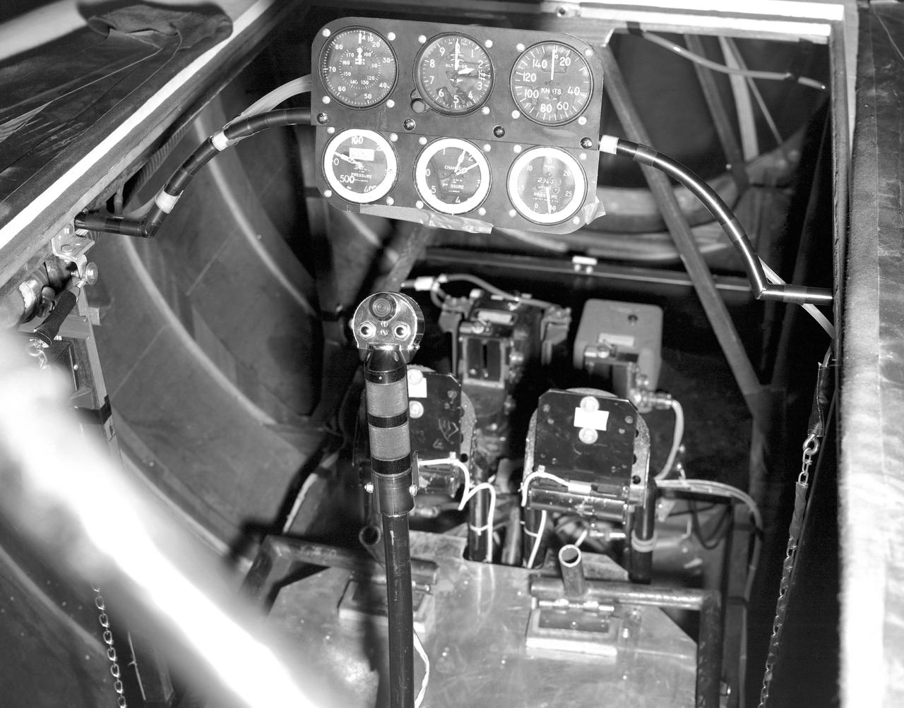
This photo shows the cockpit configuration of the M2-F1 wingless lifting body. With a top speed of about 120 knots, the M2-F1 had a simple instrument panel. Besides the panel itself, the ribs of the wooden shell (left) and the control stick (center) are also visible.
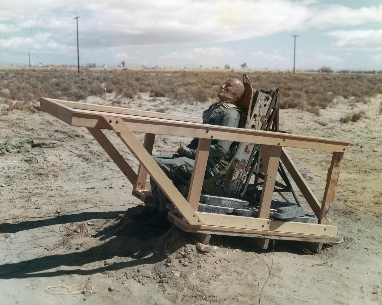
The M2-F1 was fitted with an ejection seat before the airtow flights began. The project selected the seat used in the T-37 as modified by the Weber Company to use a rocket rather than a ballistic charge for ejection. To test the ejection seat, the Flight Research Center's Dick Klein constructed a plywood mockup of the M2-F1's top deck and canopy. On the first firings, the test was unsuccessful, but on the final test the dummy in the seat landed safely. The M2-F1 ejection seat was later used in the two Lunar Landing Research Vehicles and the three Lunar Landing Training Vehicles. Three of them crashed, but in each case the pilot ejected from the vehicle successfully.
After the grounding of the M2-F1 in 1966, it was kept in outside storage on the Dryden complex. After several years, its fabric and plywood structure was damaged by the sun and weather. Restoration of the vehicle began in February 1994 under the leadership of NASA retiree Dick Fischer, with other retirees who had originally worked on the M2-F1's construction and flight research three decades before also participating. The photo shows the now-restored M2-F1 returning to the site of its flight research, now called the Dryden Flight Research Center, on 22 August 1997.
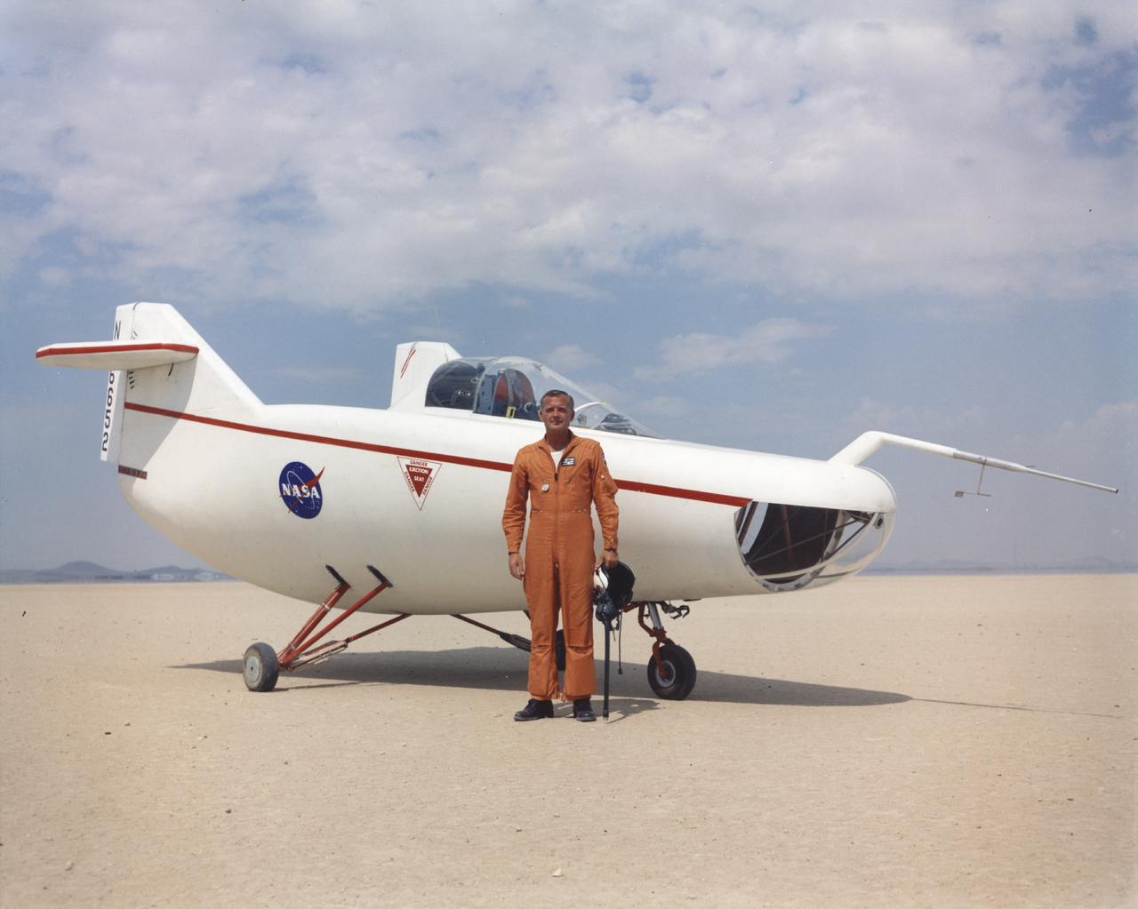
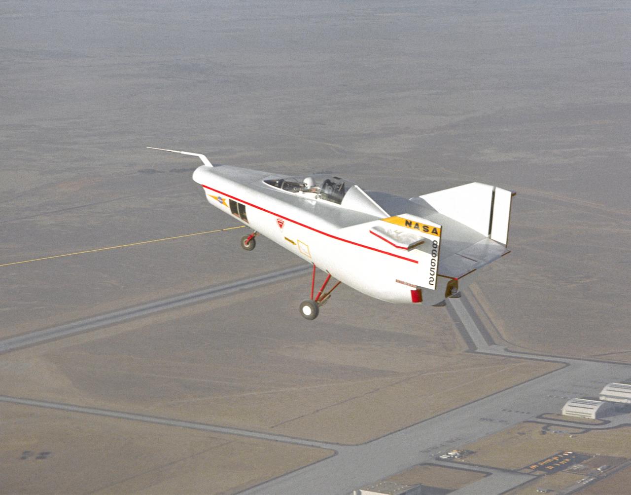
NASA Flight Research Pilot Milt Thompson, shown here on the lakebed with the M2-F1 lifting body, was an early backer of R. Dale Reed's lifting-body proposal. He urged Flight Research Center director Paul Bikle to approve the M2-F1's construction. Thompson also made the first glide flights in both the M2-F1 and its successor, the heavyweight M2-F2.
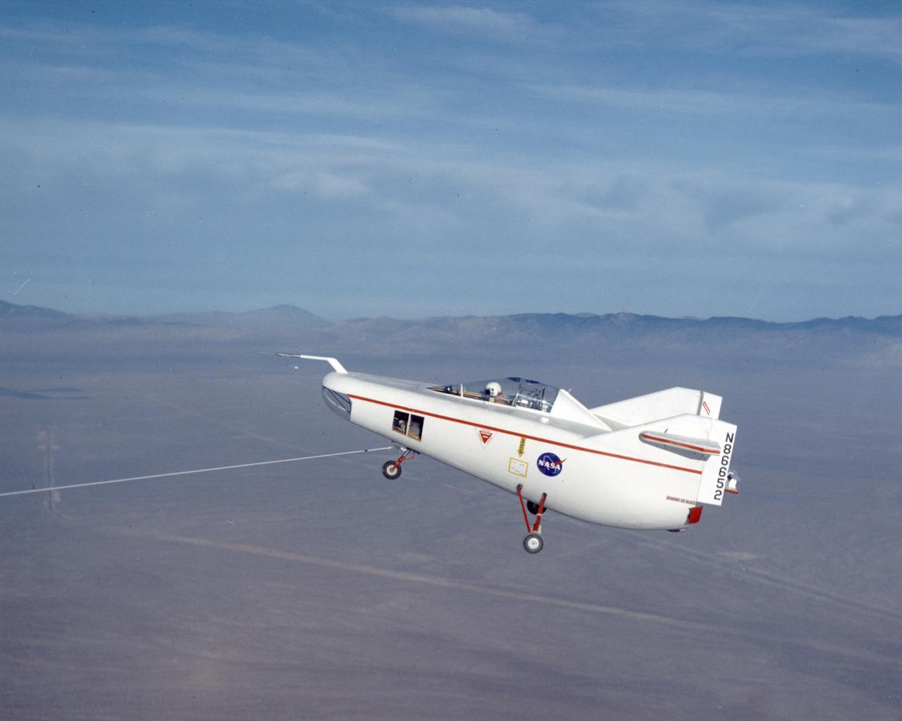
Following the first M2-F1 airtow flight on 16 August 1963, the Flight Research Center used the vehicle for both research flights and to check out new lifting-body pilots. These included Bruce Peterson, Don Mallick, Fred Haise, and Bill Dana from NASA. Air Force pilots who flew the M2-F1 included Chuck Yeager, Jerry Gentry, Joe Engle, Jim Wood, and Don Sorlie, although Wood, Haise, and Engle only flew on car tows. In the three years between the first and last flights of the M2-F1, it made about 400 car tows and 77 air tows.
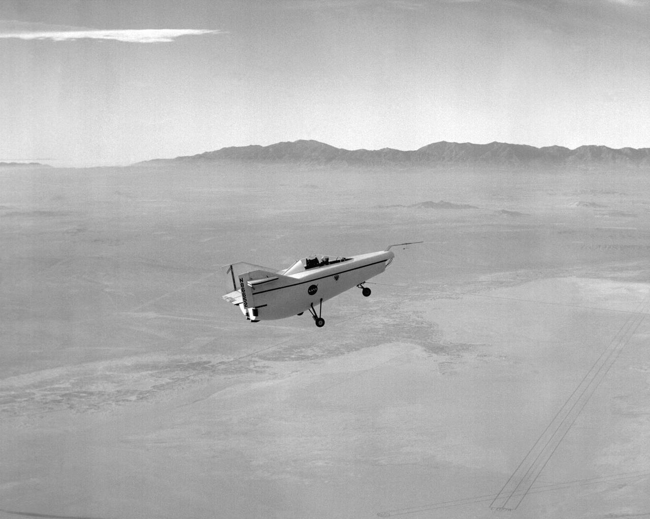
After initial ground-tow flights of the M2-F1 using the Pontiac as a tow vehicle, the way was clear to make air tows behind a C-47. The first air tow took place on 16 August 1963. Pilot Milt Thompson found that the M2-F1 flew well, with good control. This first flight lasted less than two minutes from tow-line release to touchdown. The descent rate was 4,000 feet per minute.
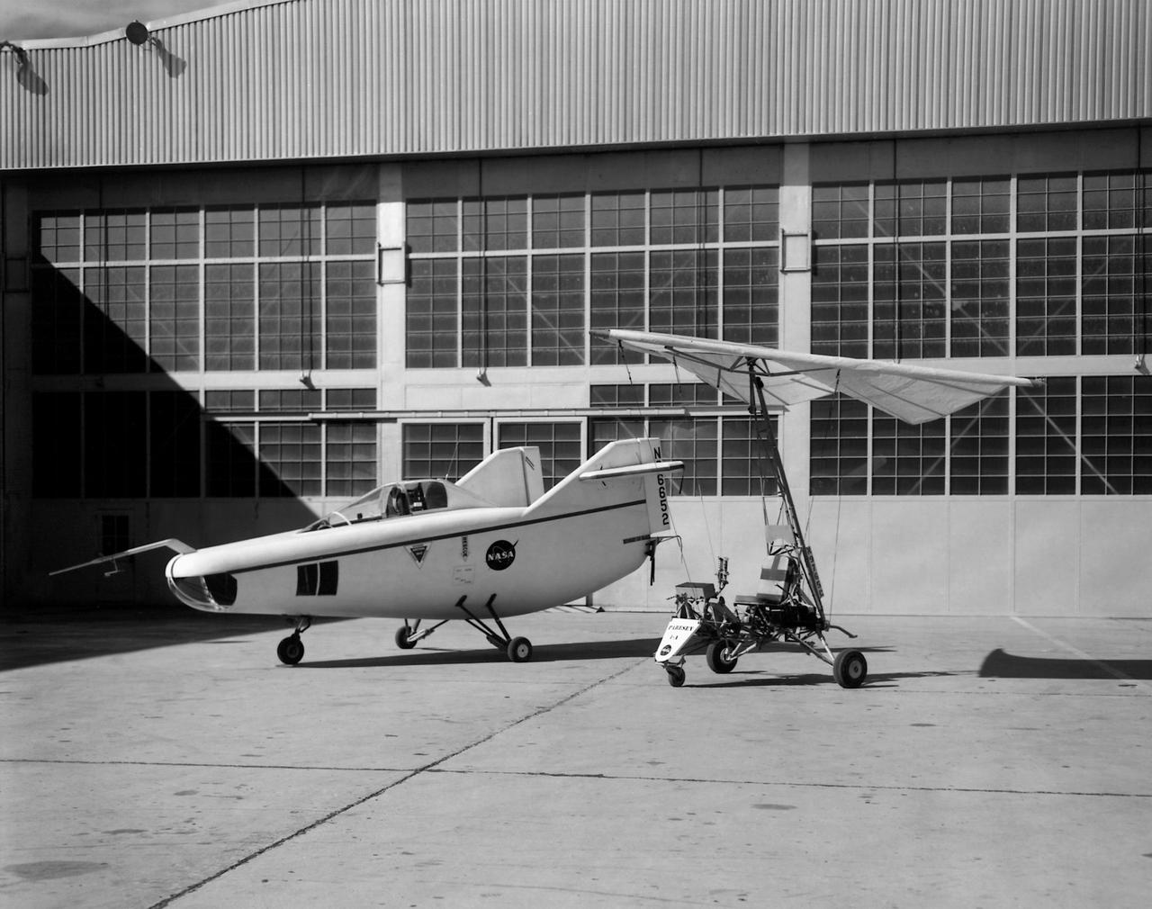
In this photo of the M2-F1 lifting body and the Paresev 1B on the ramp, the viewer sees two vehicles representing different approaches to building a research craft to simulate a spacecraft able to land on the ground instead of splashing down in the ocean as the Mercury capsules did. The M2-F1 was a lifting body, a shape able to re-enter from orbit and land. The Paresev (Paraglider Research Vehicle) used a Rogallo wing that could be (but never was) used to replace a conventional parachute for landing a capsule-type spacecraft, allowing it to make a controlled landing on the ground.