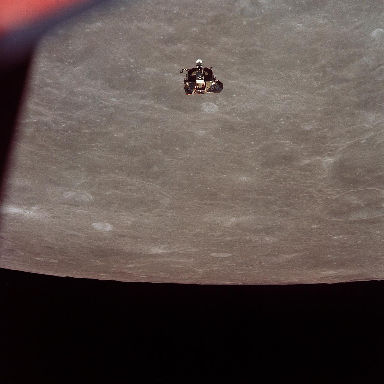
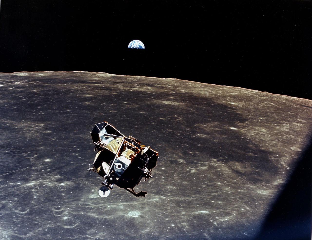
AS11-44-6626 (21 July 1969) --- The Apollo 11 Lunar Module (LM) ascent stage, with astronauts Neil A. Armstrong and Edwin E. Aldrin Jr. aboard, is photographed from the Command and Service Modules (CSM) in lunar orbit. Astronaut Michael Collins, command module pilot, remained with the CSM in lunar orbit while Armstrong and Aldrin explored the moon. The LM is approaching from below. The coordinates of the center of the lunar terrain seen below is located at 102 degrees east longitude and 1 degree north latitude.
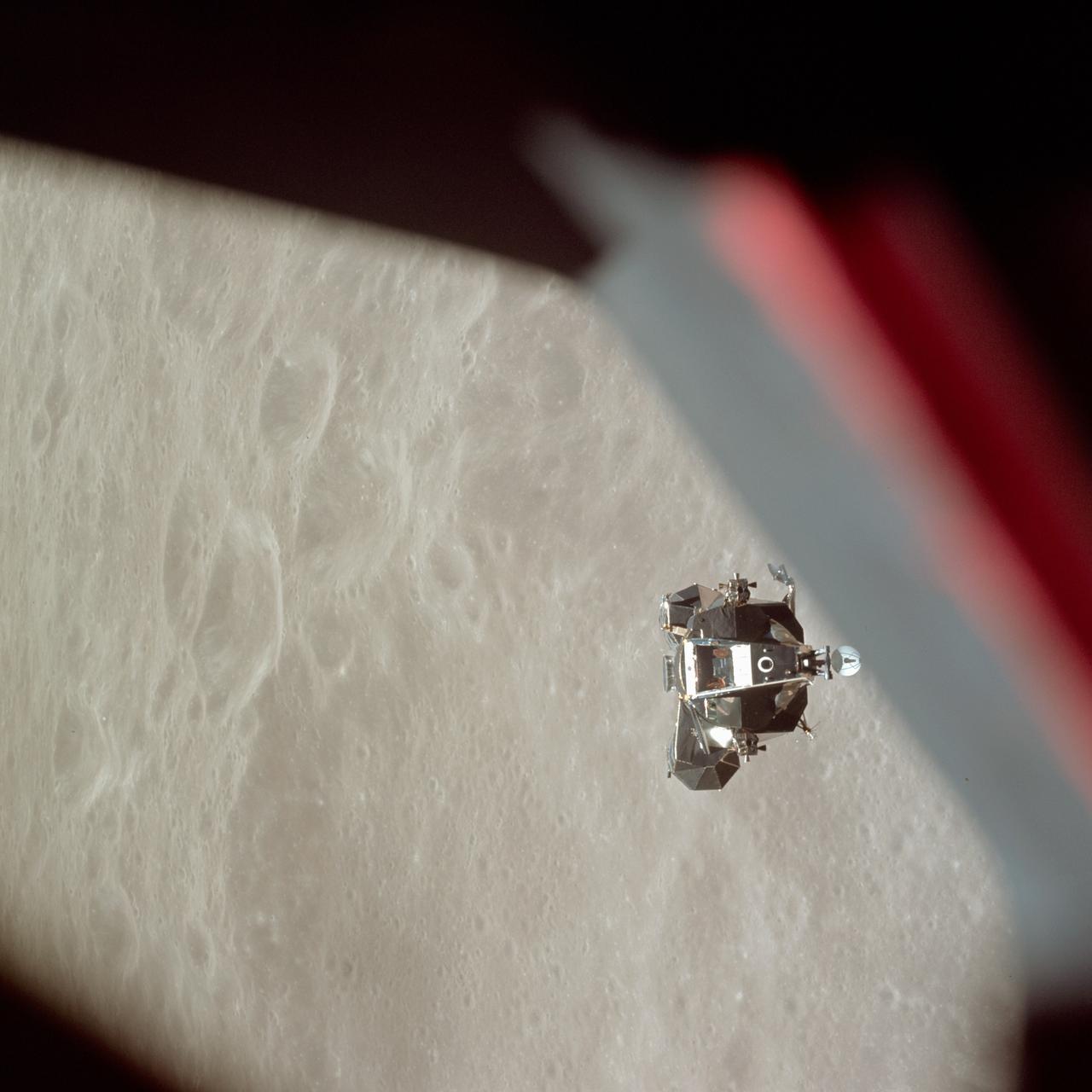
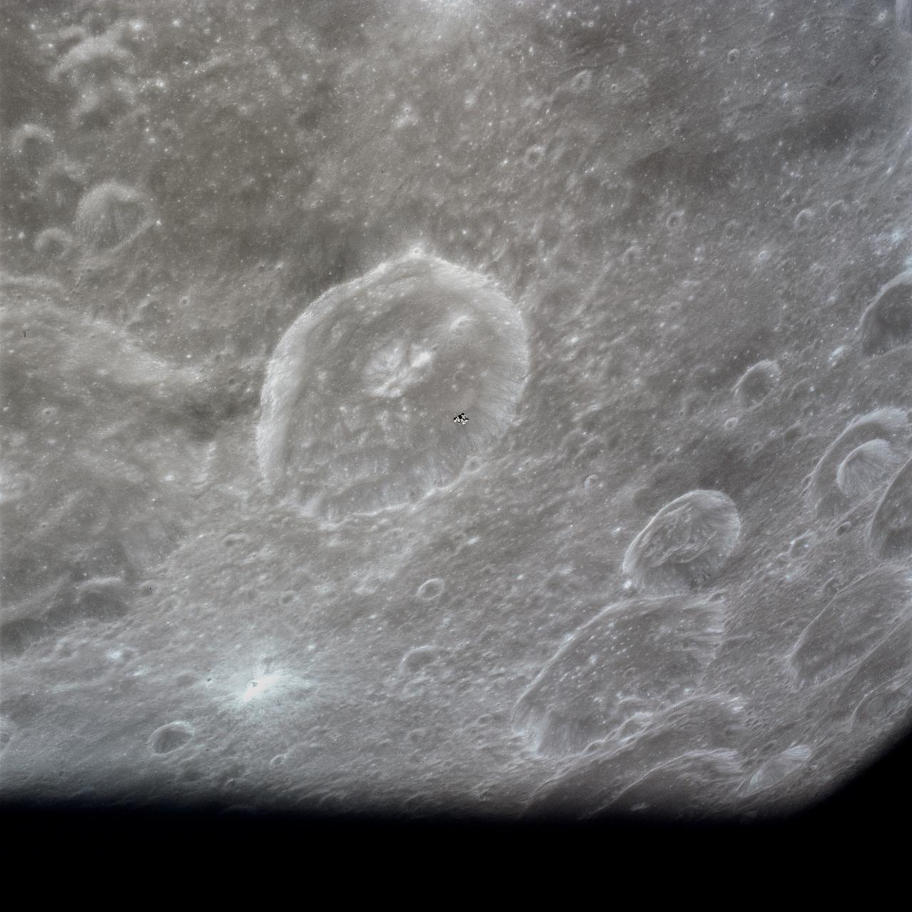
AS10-34-5112 (26 May 1969) --- The ascent stage of the Apollo 10 Lunar Module (LM) is photographed from the Command Module prior to docking in lunar orbit. The LM is approaching the Command and Service Modules from below. The LM descent stage had already been jettisoned. The lunar surface in the background is near, but beyond the eastern limb of the moon as viewed from Earth (about 120 degrees east longitude). The red/blue diagonal line is the spacecraft window.
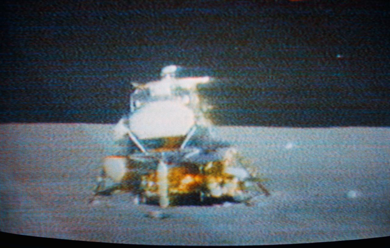
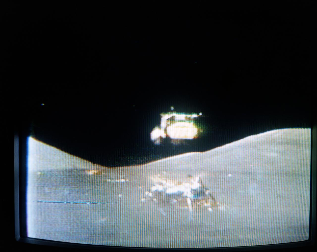
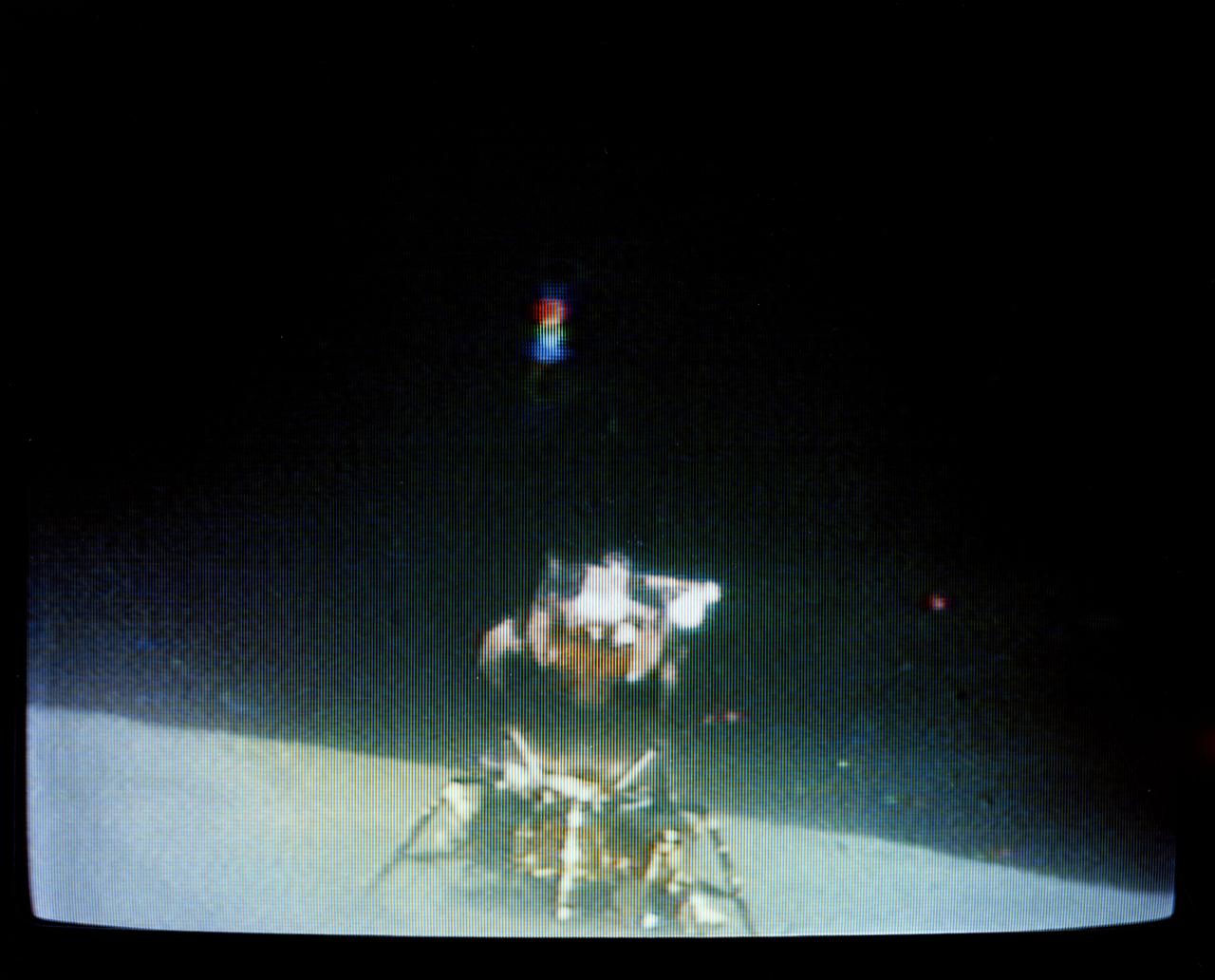
S71-41511 (2 Aug. 1971) --- The Apollo 15 Lunar Module (LM) "Falcon" is seen only seconds before ascent stage liftoff in this color reproduction taken from a transmission made by the RCA color television camera mounted on the Lunar Roving Vehicle (LRV). The LRV was parked about 300 feet east of the LM. The LRV-mounted TV camera, remotely controlled from the Mission Control Center (MCC), made it possible for people on Earth to watch the LM's launch from the moon. The LM liftoff was at 171:37 ground elapsed time. The "Falcon" ascent stage, with astronauts David R. Scott, commander; and James B. Irwin, lunar module pilot, aboard, returned from the lunar surface to rejoin the Command and Service Modules (CSM) orbiting the moon. Astronaut Alfred M. Worden, command module pilot, remained with the CSM in lunar orbit while Scott and Irwin explored the moon. The LM descent stage is used as a launching platform and remains behind on the moon. This is part one of a four-part sequence.

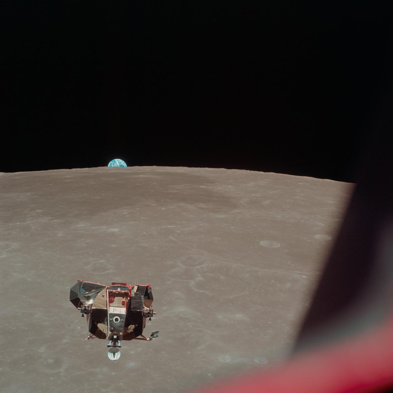
AS11-44-6642 (21 July 1969) --- The Apollo 11 Lunar Module ascent stage, with astronauts Neil A. Armstrong and Edwin E. Aldrin Jr. aboard, is photographed from the Command and Service Modules (CSM) during rendezvous in lunar orbit. The Lunar Module (LM) was making its docking approach to the CSM. Astronaut Michael Collins remained with the CSM in lunar orbit while the other two crewmen explored the lunar surface. The large, dark-colored area in the background is Smyth's Sea, centered at 85 degrees east longitude and 2 degrees south latitude on the lunar surface (nearside). This view looks west. The Earth rises above the lunar horizon.
AS11-44-6634 (21 July 1969) --- The Apollo 11 Lunar Module (LM) ascent stage, with astronauts Neil A. Armstrong and Edwin E. Aldrin Jr. onboard, is photographed from the Command and Services Modules (CSM) in lunar orbit. This view is looking west with the Earth rising above the lunar horizon. Astronaut Michael Collins remained with the CSM in lunar orbit while Armstrong and Aldrin explored the moon. The LM is approaching from below. The maze area in the background is Smyth's Sea. At right center is International Astronomical Union crater No. 189.
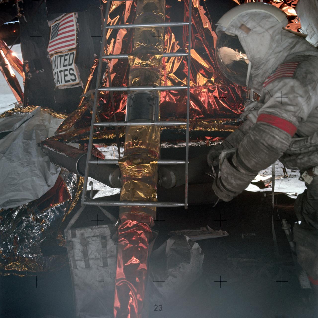
Astronaut Eugene A. Cernan, Apollo 17 commander, prepares to mount ladder to lunar module ascent stage. Note the plaque attached to the ladder which will be left with the descent stage when the mission lifts off from the lunar surface.
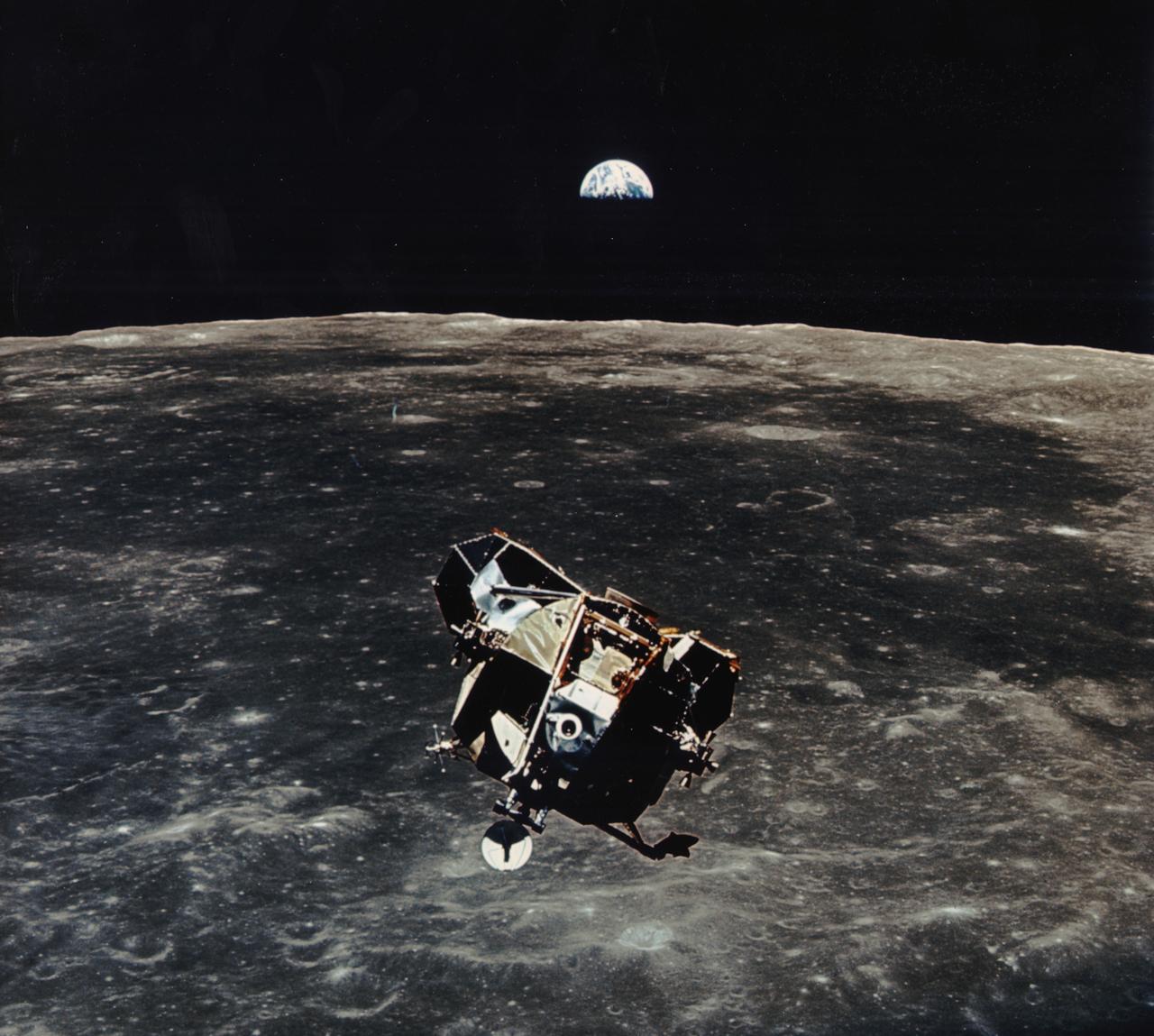
The Apollo 11 mission launched from the Kennedy Space Center (KSC) in Florida via the Marshall Space Flight Center (MSFC) developed Saturn V launch vehicle on July 16, 1969 and safely returned to Earth on July 24, 1969. Aboard the space craft were astronauts Neil A. Armstrong, commander; Michael Collins, Command Module (CM) pilot; and Edwin E. (Buzz) Aldrin Jr., Lunar Module (LM) pilot. With the success of Apollo 11, the national objective to land men on the Moon and return them safely to Earth had been accomplished. After 2½ hours of surface exploration, astronauts Neil Armstrong and Edwin Aldrin returned to the LM “Eagle” for rest, eating, and checkout of the vehicle in preparation for liftoff. The LM was a two part spacecraft. Its lower or descent stage had the landing gear, engines, and fuel needed for the landing. When the LM blasted off the Moon, the descent stage served as the launching pad for its companion ascent stage, which was also home for the two astronauts on the surface of the Moon. The LM was full of gear with which to communicate, navigate, and rendezvous. It also had its own propulsion system, and an engine to lift it off the Moon and send it on a course toward the orbiting CM. In this photograph, the ascent stage is seen back dropped by Earth just prior to its rendezvous with the CM.

S69-59547 (20 Nov. 1969) --- The seismometer reading from the impact made by the Lunar Module ascent stage when it struck the lunar surface. The impact was registered by the Passive Seismic Experiment Package which was deployed on the moon by the Apollo 12 astronauts. PSEP, which is a component of the Apollo Lunar Surface Experiments Package, will detect surface tilt produced by tidal deformations, moonquakes, and meteorite impacts. The LM's ascent stage was jettisoned and sent journeying toward impact on the moon after astronauts Charles Conrad Jr. and Alan L. Bean returned to lunar orbit and rejoined astronaut Richard F. Gordon Jr. in the Command and Service Modules. Information from the PSEP is transmitted to Earth through the ALSEP's central station and monitored by equipment at the Manned Spacecraft Center.
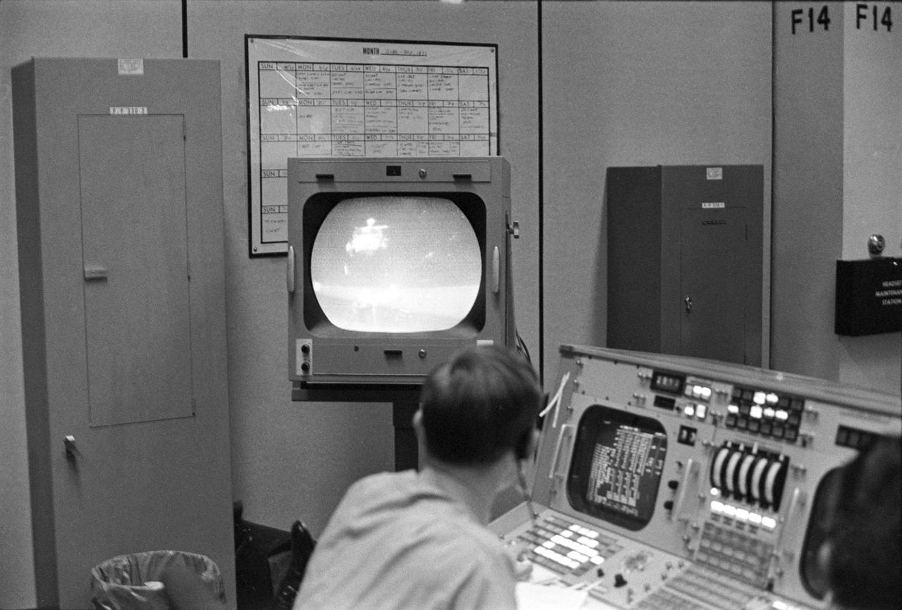
View of a photograph of the television (TV) monitor in the MCC showing a picture being transmitted from the color TV camera mounted on the parked Lunar Roving Vehicle (LRV) at the Hadley-Apennine Landing Site showing the liftoff of the Apollo 15 Lunar Module (LM) Ascent Stage from the Lunar surface. MSC, Houston, TX
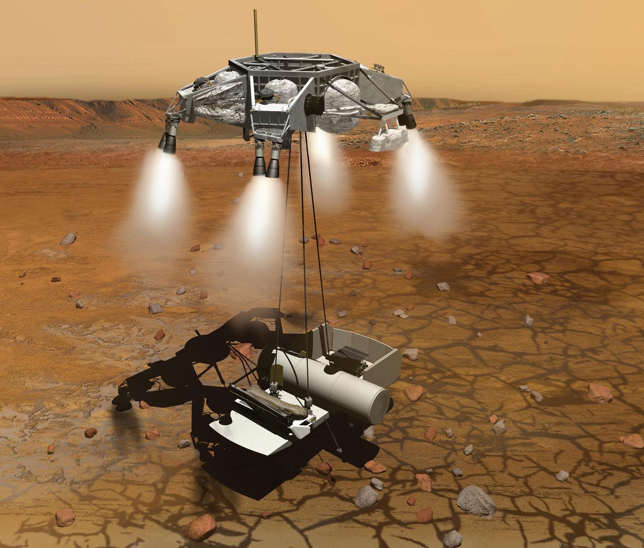
This artist concept of a proposed Mars sample return mission portrays a rocket-powered descent stage lowering a sample-retrieving rover and an ascent vehicle to the surface.
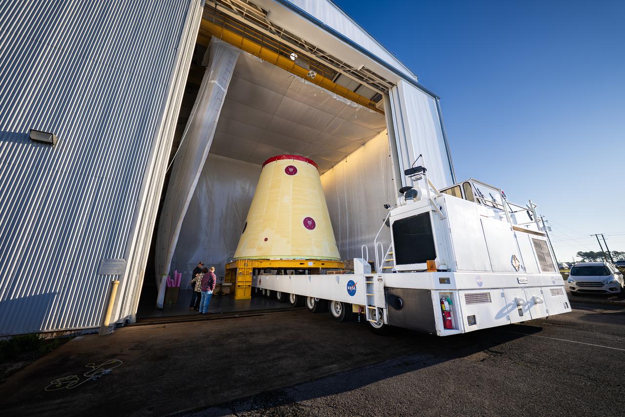
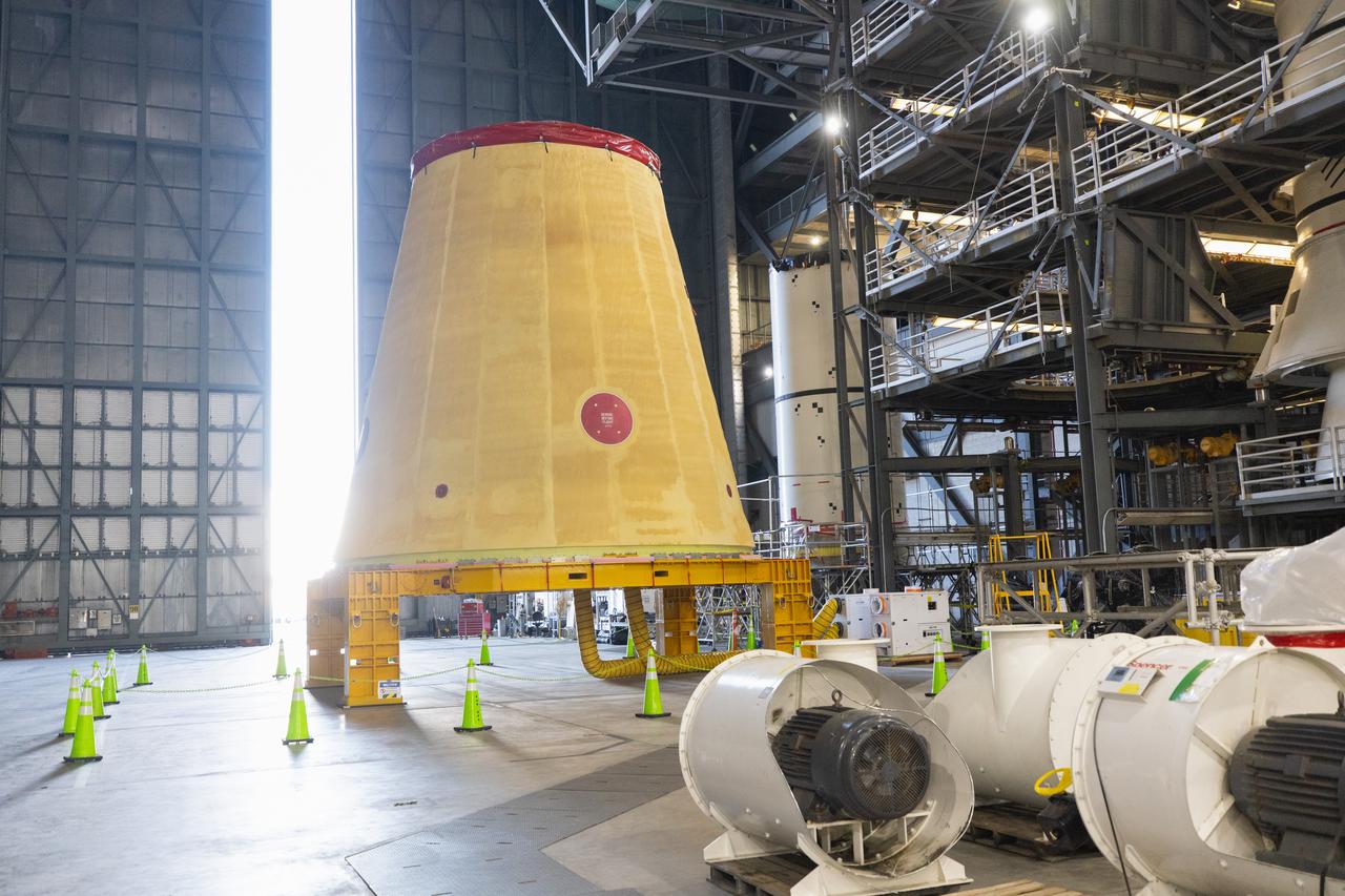
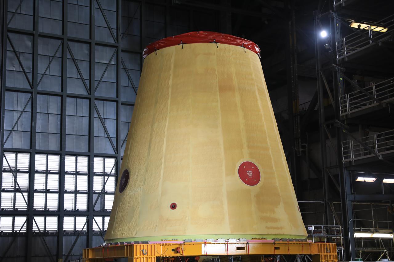
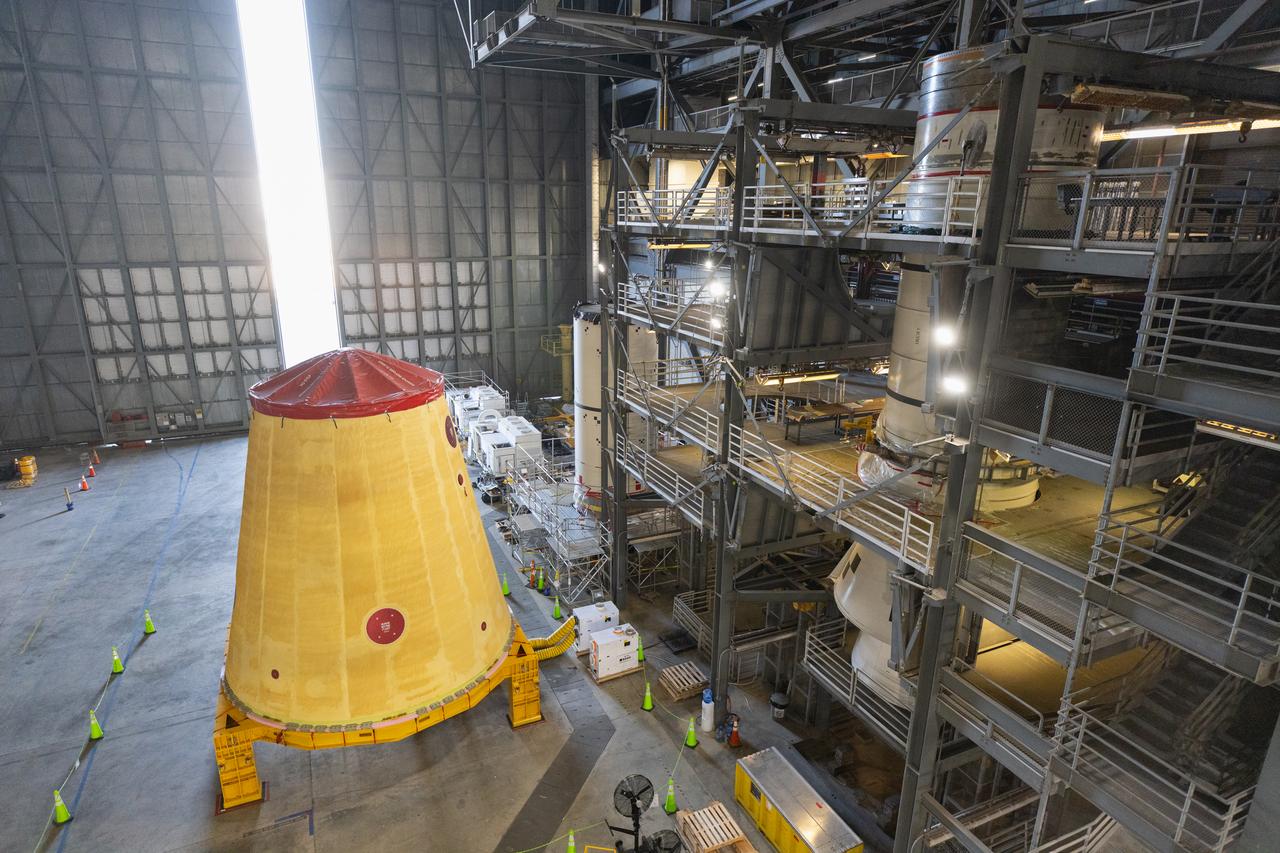
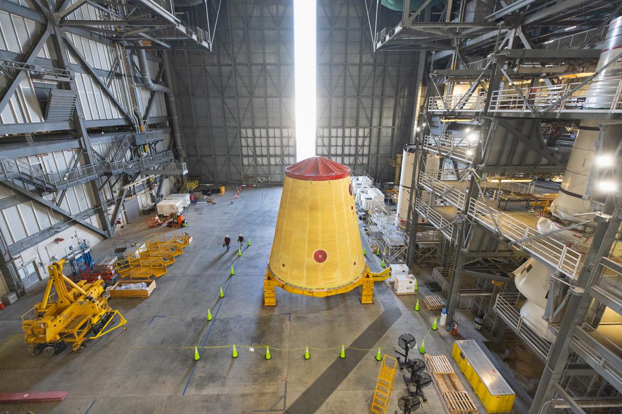
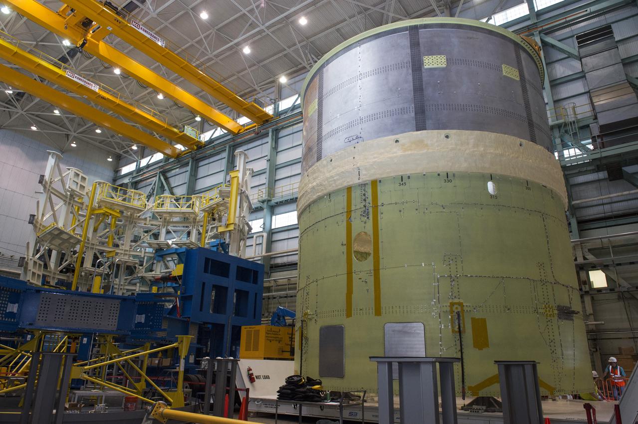
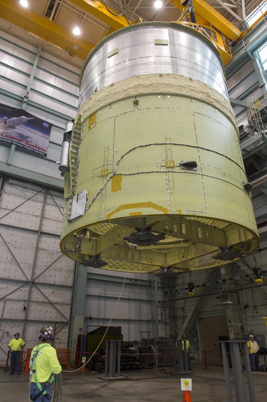
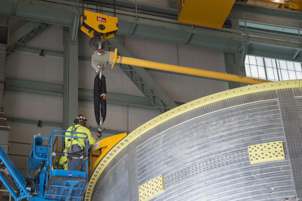
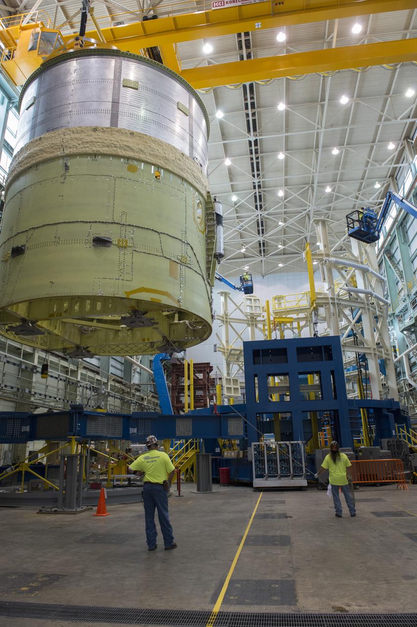
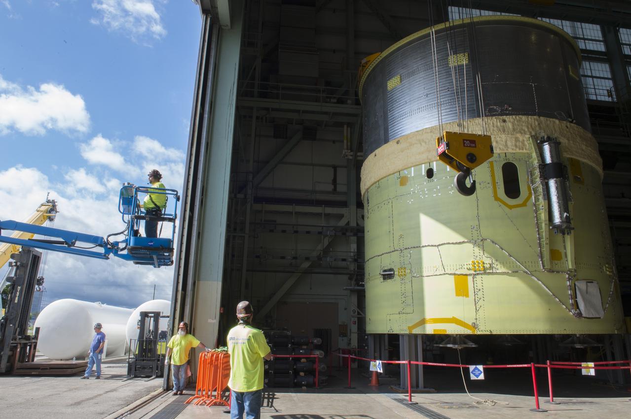
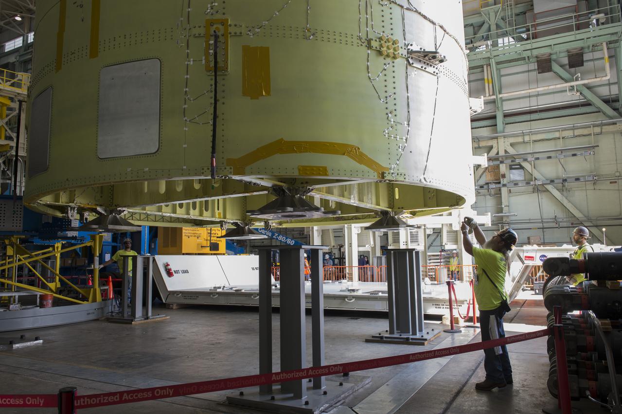
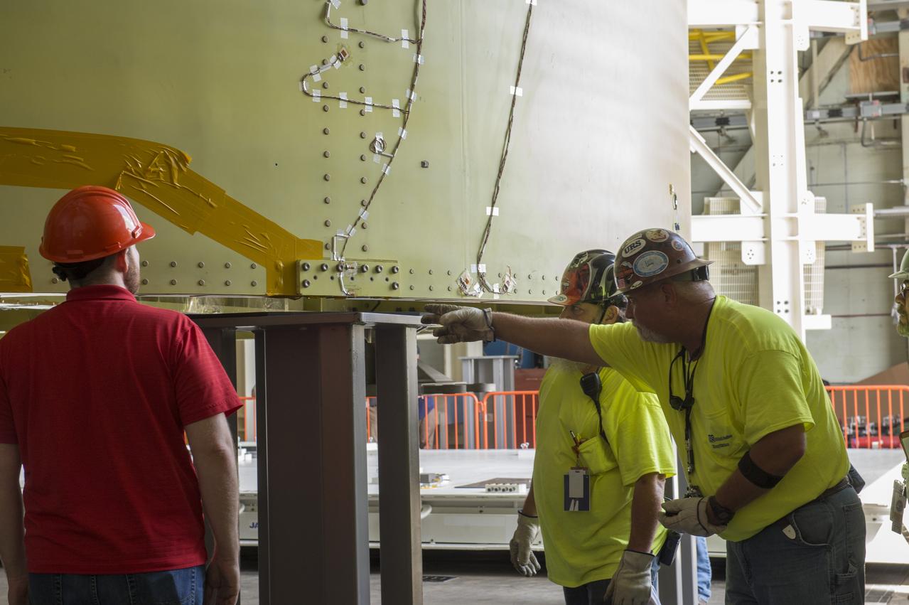
These images and videos show technicians at NASA’s Marshall Space Flight Center in Huntsville, Alabama, March 17, 2025, moving the completed launch vehicle stage adapter for Artemis III from Building 4649 to Building 4708 where it will remain until it is time to ship the hardware to NASA’s Kennedy Space Center in Florida. The cone-shaped hardware connects the SLS (Space Launch System) rocket to the upper stage, the interim cryogenic propulsion stage, and protects the rocket’s flight computers, avionics, and electrical devices during launch and ascent during the Artemis missions.

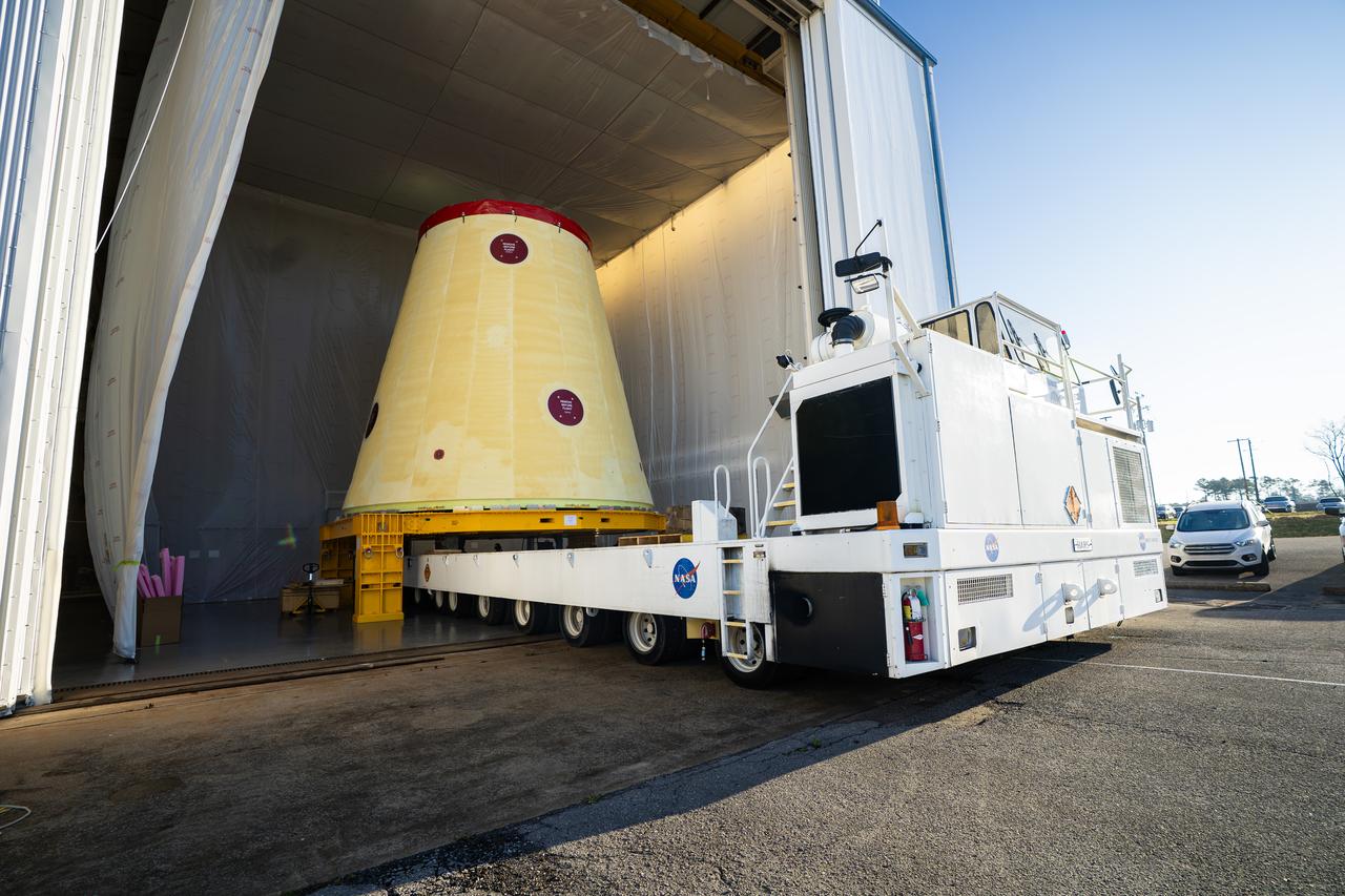
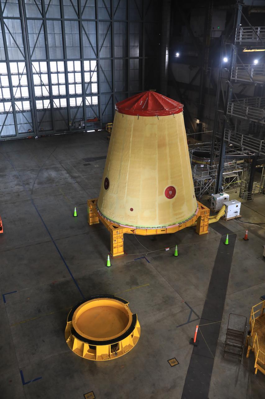
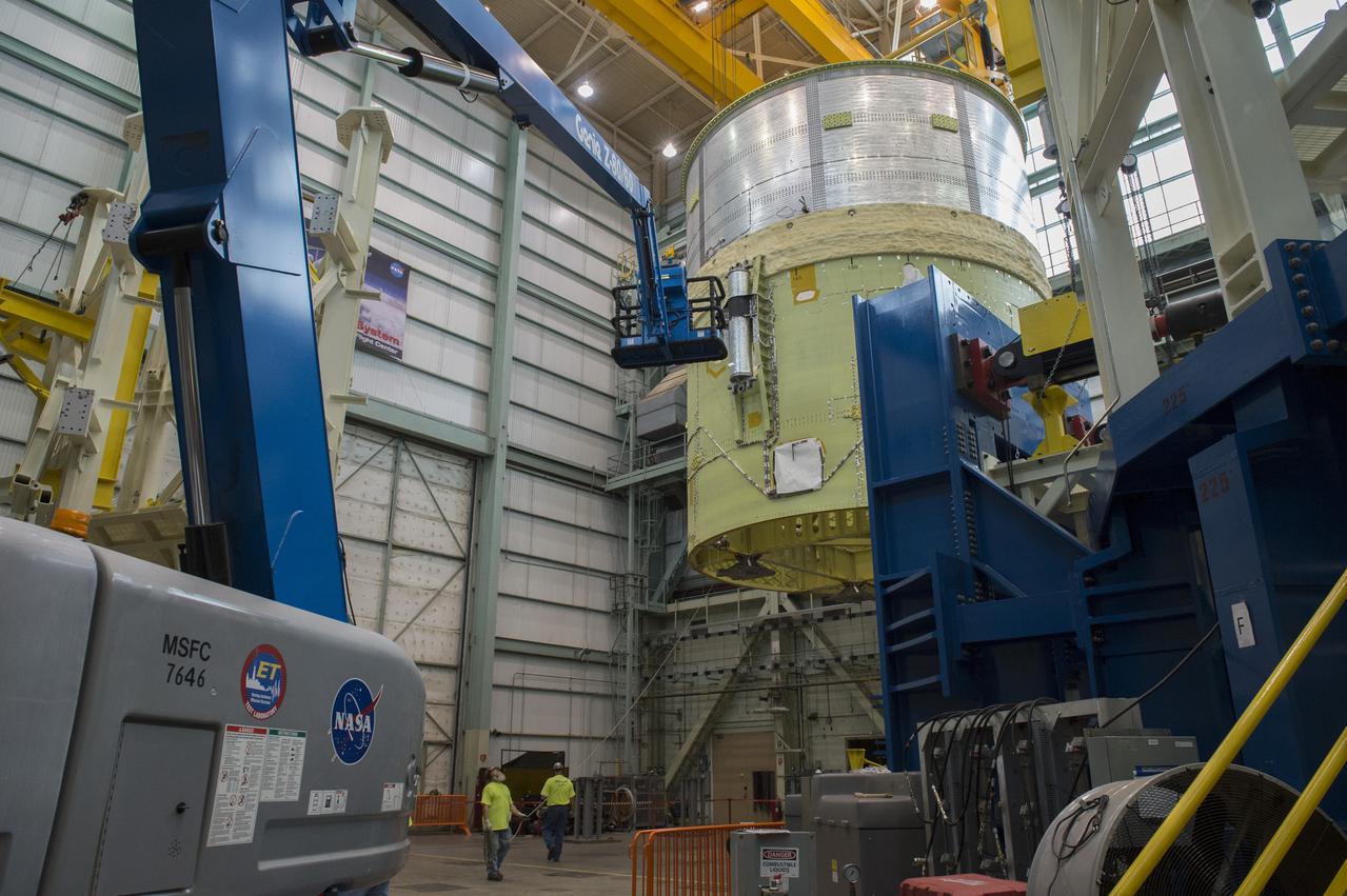
These images and videos show technicians at NASA’s Marshall Space Flight Center in Huntsville, Alabama, March 17, 2025, moving the completed launch vehicle stage adapter for Artemis III from Building 4649 to Building 4708 where it will remain until it is time to ship the hardware to NASA’s Kennedy Space Center in Florida. The cone-shaped hardware connects the SLS (Space Launch System) rocket to the upper stage, the interim cryogenic propulsion stage, and protects the rocket’s flight computers, avionics, and electrical devices during launch and ascent during the Artemis missions.
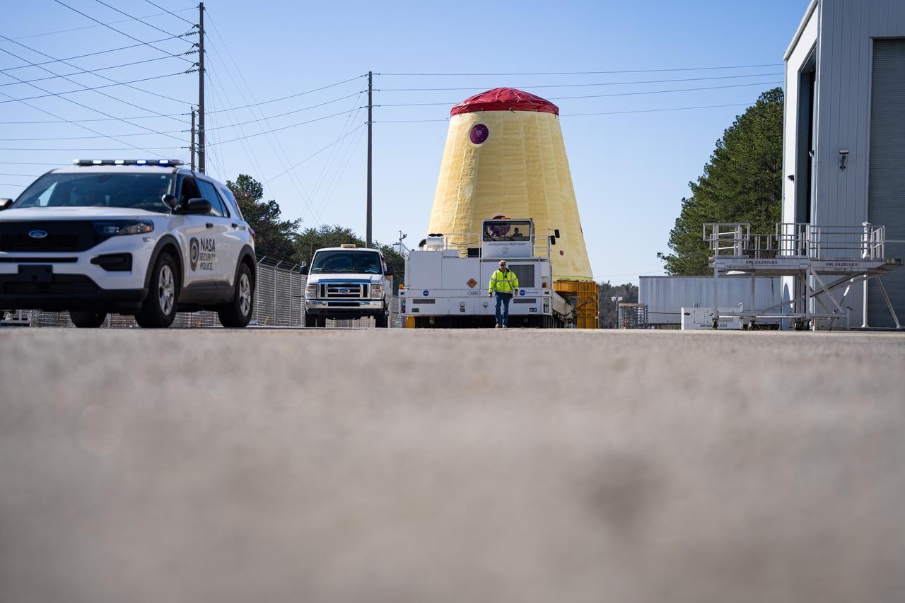
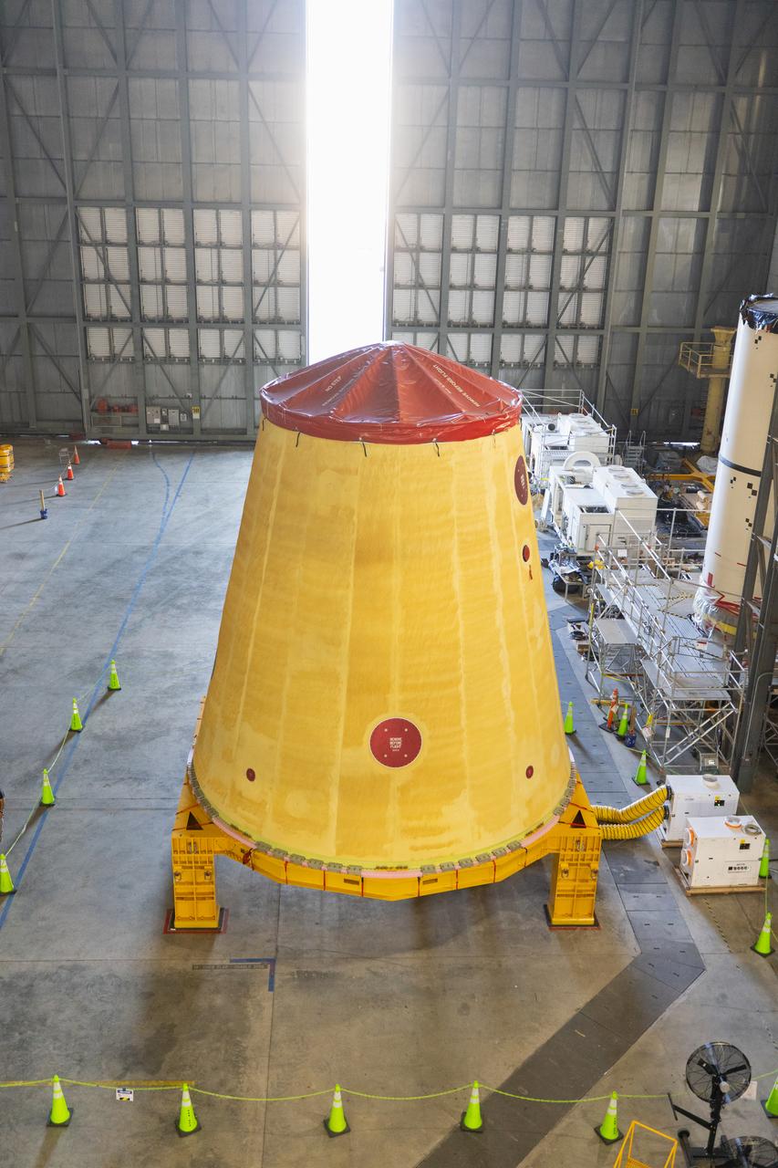
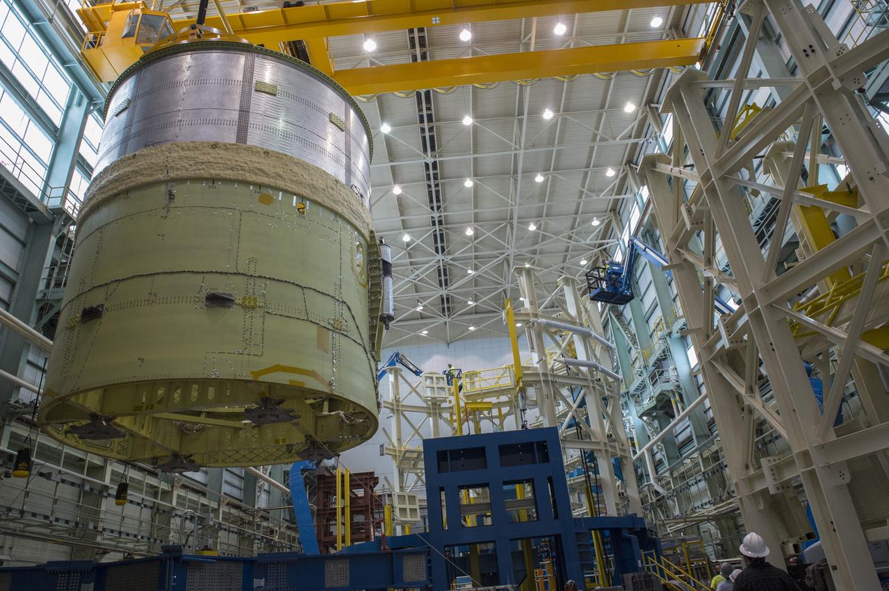
These images and videos show technicians at NASA’s Marshall Space Flight Center in Huntsville, Alabama, March 17, 2025, moving the completed launch vehicle stage adapter for Artemis III from Building 4649 to Building 4708 where it will remain until it is time to ship the hardware to NASA’s Kennedy Space Center in Florida. The cone-shaped hardware connects the SLS (Space Launch System) rocket to the upper stage, the interim cryogenic propulsion stage, and protects the rocket’s flight computers, avionics, and electrical devices during launch and ascent during the Artemis missions.
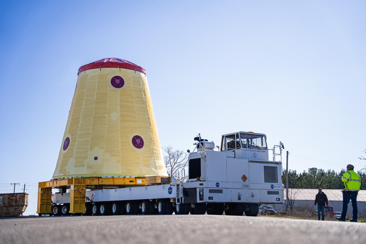
These images and videos show technicians at NASA’s Marshall Space Flight Center in Huntsville, Alabama, March 17, 2025, moving the completed launch vehicle stage adapter for Artemis III from Building 4649 to Building 4708, where it will remain until it is time to ship the hardware to NASA’s Kennedy Space Center in Florida. The cone-shaped hardware connects the SLS (Space Launch System) rocket to the upper stage, the interim cryogenic propulsion stage, and protects the rocket’s flight computers, avionics, and electrical devices during launch and ascent during the Artemis missions.
These images and videos show technicians at NASA’s Marshall Space Flight Center in Huntsville, Alabama, March 17, 2025, moving the completed launch vehicle stage adapter for Artemis III from Building 4649 to Building 4708 where it will remain until it is time to ship the hardware to NASA’s Kennedy Space Center in Florida. The cone-shaped hardware connects the SLS (Space Launch System) rocket to the upper stage, the interim cryogenic propulsion stage, and protects the rocket’s flight computers, avionics, and electrical devices during launch and ascent during the Artemis missions.
S72-55421 (14 Dec. 1972) --- The Apollo 17 Lunar Module (LM) "Challenger" ascent stage leaves the Taurus-Littrow landing site as it makes its spectacular liftoff from the lunar surface, as seen in this reproduction taken from a color television transmission made by the color RCA TV camera mounted on the Lunar Roving Vehicle (LRV). The LRV-mounted TV camera, remotely controlled from the Mission Control Center (MCC) in Houston, made it possible for people on Earth to watch the fantastic event. The LM liftoff was at 188:01:36 ground elapsed time, 4:54:36 p.m. (CST), Thursday, Dec. 14, 1972. The LM ascent stage, with astronauts Eugene A. Cernan and Harrison H. Schmitt aboard, returned from the lunar surface to rejoin the Command and Service Modules (CSM) orbiting the moon. Astronaut Ronald E. Evans remained with the CSM in lunar orbit while Cernan and Schmitt explored the moon. The LM descent stage is used as a launching platform and remains behind on the moon. Here, the two stages have completely separated and the ascent stage is headed skyward.
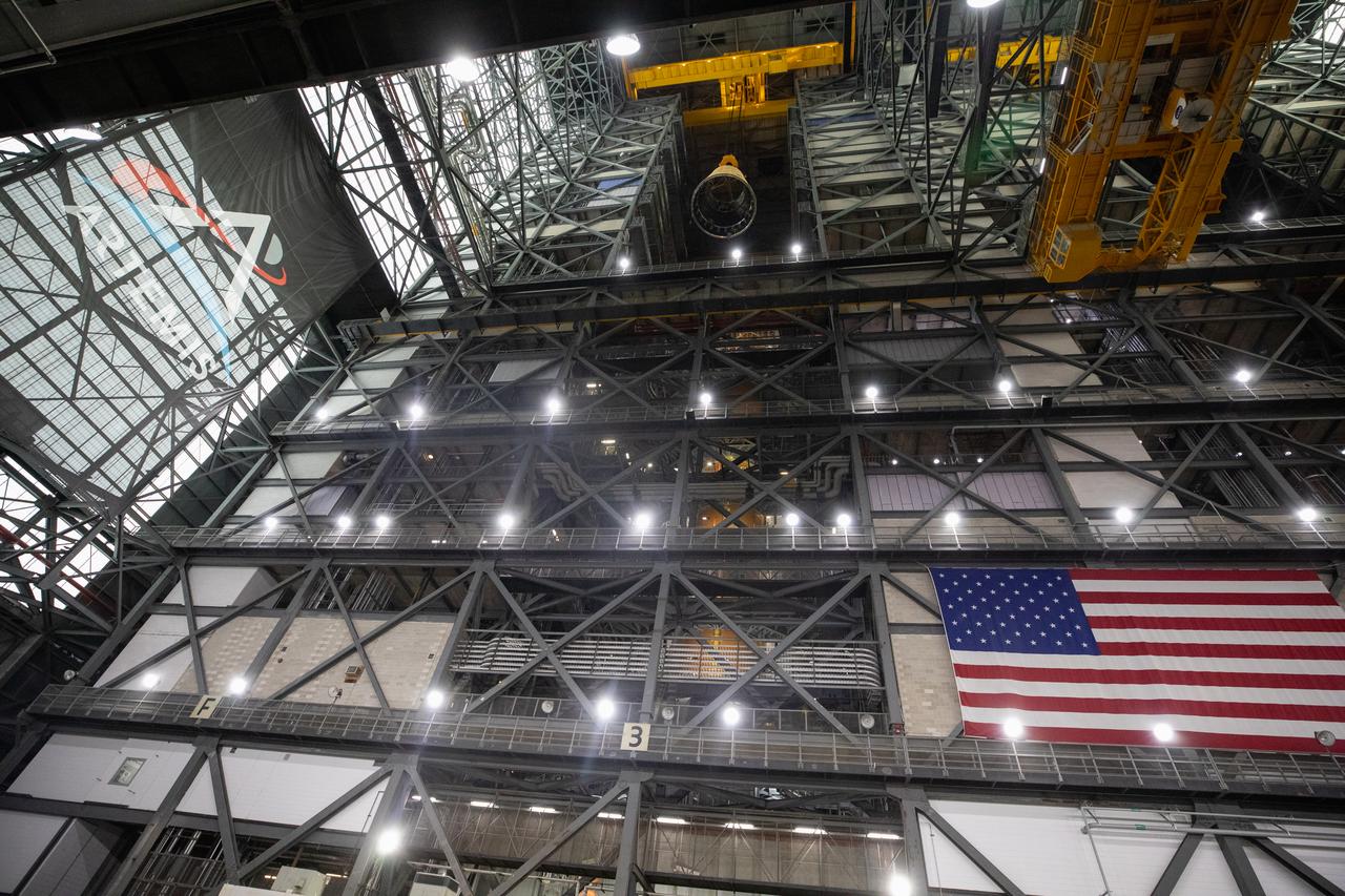
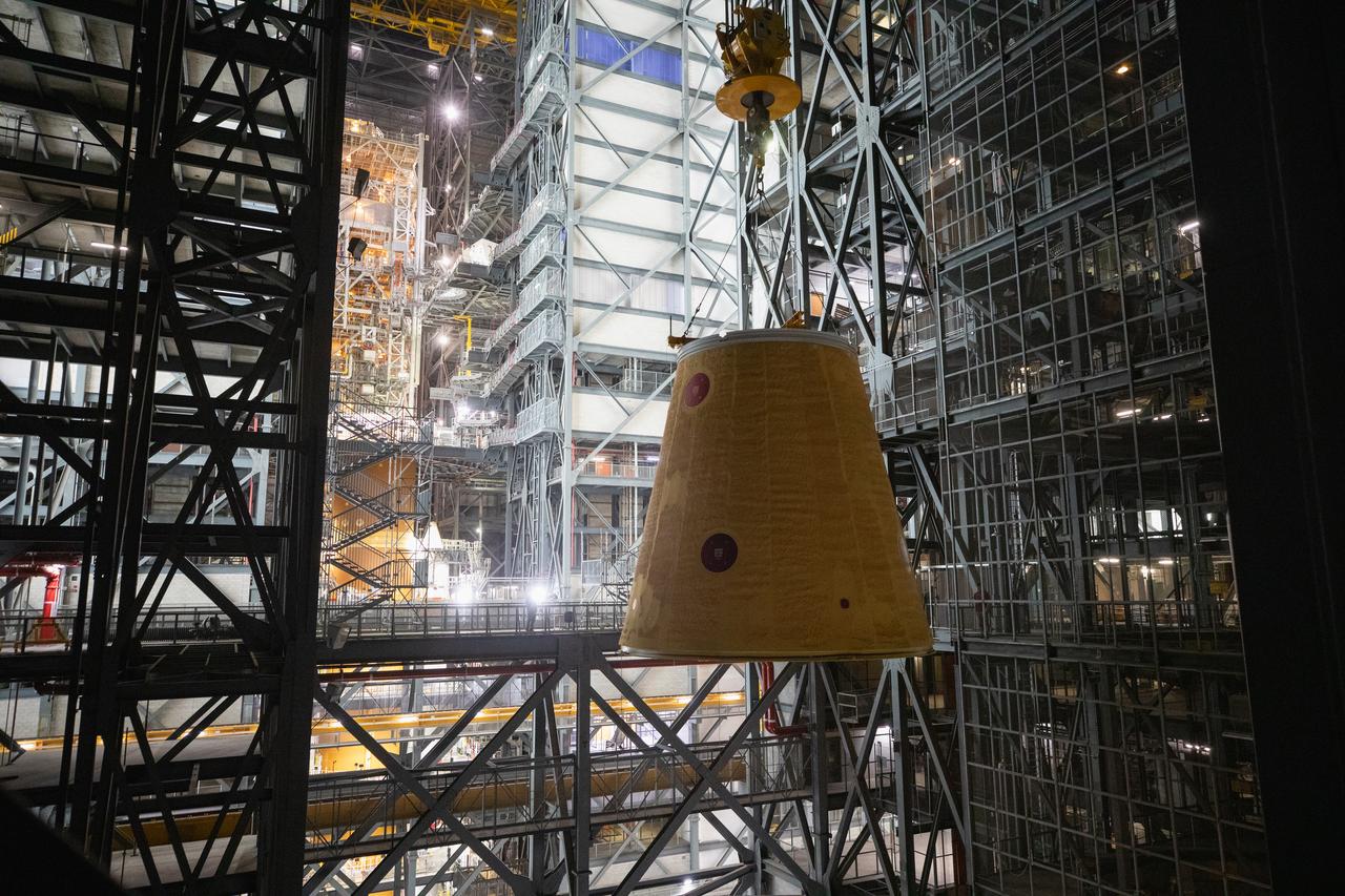
NASA’s Artemis II hardware, the launch vehicle stage adapter, is inside High Bay 4 on Thursday, March 20, 2025, at the Vehicle Assembly Building at NASA’s Kennedy Space Center in Florida ahead of rocket stacking operations. The cone shaped launch vehicle stage adapter connects the SLS (Space Launch System) Moon rocket to the upper stage, the interim cryogenic propulsion stage, and protects the rocket’s flight computers, avionics, and electrical devices during launch and ascent during the Artemis missions.
NASA’s Artemis II hardware, the launch vehicle stage adapter, awaits stacking operations at the Vehicle Assembly Building at NASA’s Kennedy Space Center in Florida on Monday, Sept. 9, 2024. The cone shaped launch vehicle stage adapter connects to NASA’s SLS (Space Launch System) rocket to the upper stage, the interim cryogenic propulsion stage, and protects the rocket’s flight computers, avionics, and electrical devices during launch and ascent.
NASA’s Artemis II hardware, the launch vehicle stage adapter, is inside High Bay 4 on Thursday, March 20, 2025, at the Vehicle Assembly Building at NASA’s Kennedy Space Center in Florida ahead of rocket stacking operations. The cone shaped launch vehicle stage adapter connects the SLS (Space Launch System) Moon rocket to the upper stage, the interim cryogenic propulsion stage, and protects the rocket’s flight computers, avionics, and electrical devices during launch and ascent during the Artemis missions.
NASA’s Artemis II hardware, the launch vehicle stage adapter, is inside High Bay 4 on Thursday, March 20, 2025, at the Vehicle Assembly Building at NASA’s Kennedy Space Center in Florida ahead of rocket stacking operations. The cone shaped launch vehicle stage adapter connects the SLS (Space Launch System) Moon rocket to the upper stage, the interim cryogenic propulsion stage, and protects the rocket’s flight computers, avionics, and electrical devices during launch and ascent during the Artemis missions.
NASA’s Artemis II hardware, the launch vehicle stage adapter, awaits stacking operations at the Vehicle Assembly Building at NASA’s Kennedy Space Center in Florida on Monday, Sept. 9, 2024. The cone shaped launch vehicle stage adapter connects to NASA’s SLS (Space Launch System) rocket to the upper stage, the interim cryogenic propulsion stage, and protects the rocket’s flight computers, avionics, and electrical devices during launch and ascent.
NASA’s Artemis II hardware, the launch vehicle stage adapter, is inside High Bay 4 on Thursday, March 20, 2025, at the Vehicle Assembly Building at NASA’s Kennedy Space Center in Florida ahead of rocket stacking operations. The cone shaped launch vehicle stage adapter connects the SLS (Space Launch System) Moon rocket to the upper stage, the interim cryogenic propulsion stage, and protects the rocket’s flight computers, avionics, and electrical devices during launch and ascent during the Artemis missions.
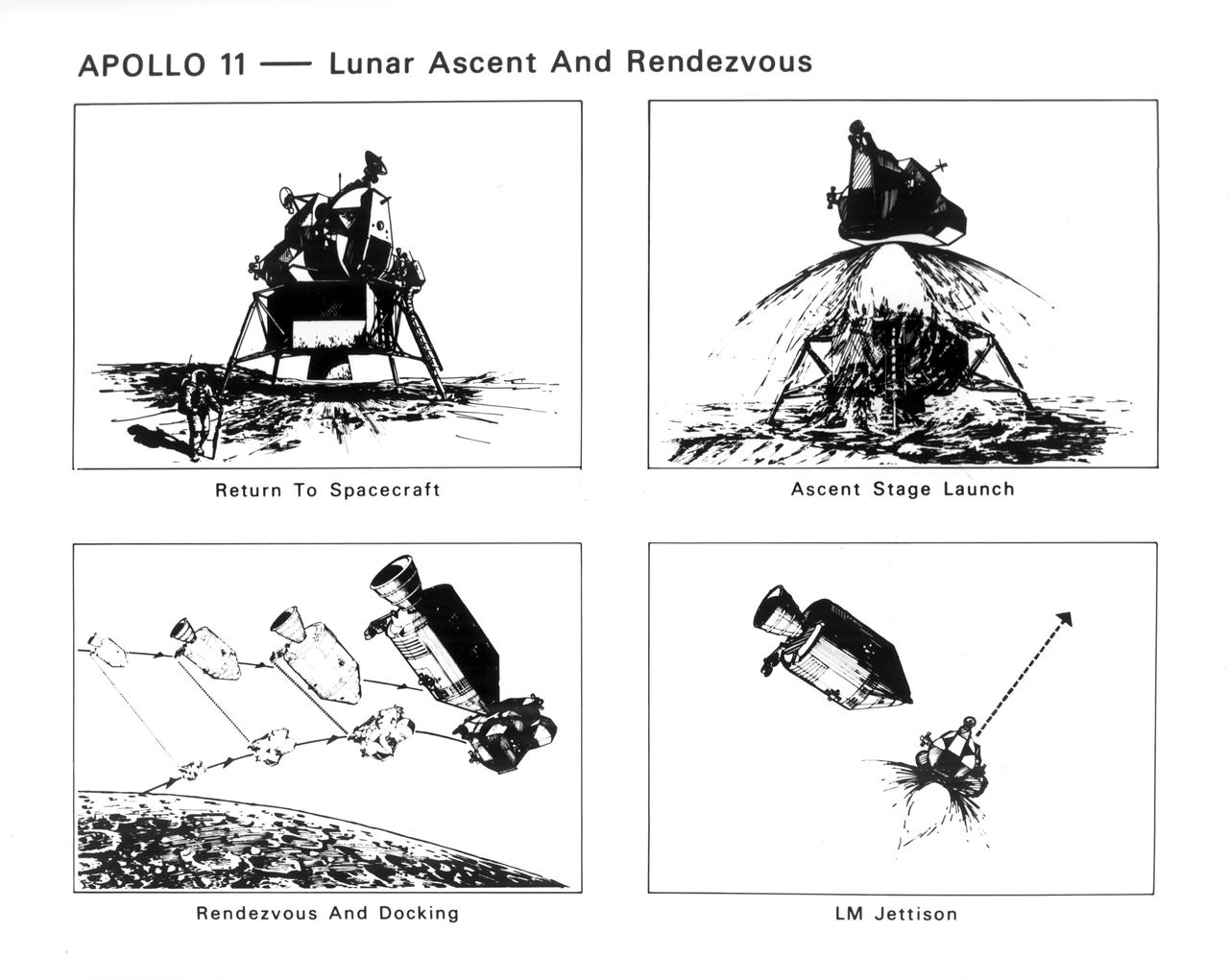
The Apollo 11 mission launched from the Kennedy Space Center (KSC) in Florida via the Marshall Space Flight Center (MSFC) developed Saturn V launch vehicle on July 16, 1969 and safely returned to Earth on July 24, 1969. Aboard the space craft were astronauts Neil A. Armstrong, commander; Michael Collins, Command Module (CM) pilot; and Edwin E. (Buzz) Aldrin Jr., Lunar Module (LM) pilot. With the success of Apollo 11, the national objective to land men on the Moon and return them safely to Earth had been accomplished. These sketches illustrate the steps taken when the astronauts left the Moon. After 2½ hours of surface exploration, astronauts Neil Armstrong and Edwin Aldrin returned to the Lunar Module (LM) “Eagle” for rest, eating, and checkout of the vehicle in preparation for liftoff. The ascent stage lifted off, using the descent stage as a launch pad. The ascent stage went into lunar orbit and moved in to dock with the orbiting CM “Columbia”. After Armstrong and Aldrin joined Collins in the CM, the engine of the LM ascent stage was fired to move it out of the same orbit.
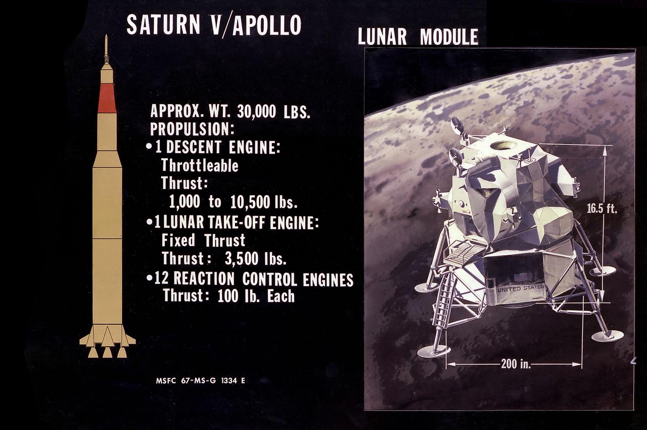
This illustration is the Lunar Module (LM) configuration. The LM was a two part spacecraft. Its lower or descent stage had the landing gear, engines, and fuel needed for the landing. When the LM blasted off the Moon, the descent stage served as the launching pad for its companion ascent stage, which was also home for the two astronauts on the surface of the Moon. The LM was full of gear with which to communicate, navigate, and rendezvous. It also had its own propulsion system, and an engine to lift it off the Moon and send it on a course toward the orbiting Command Module.
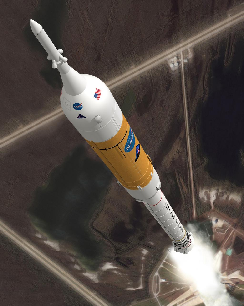
A CONCEPT IMAGE SHOWS THE ARES I CREW LAUNCH VEHICLE DURING ASCENT. ARES I IS AN IN-LINE, TWO-STAGE ROCKET CONFIGURATION TOPED BY THE ORION CREW EXPLORATION VEHICLE AND LAUNCH ABORT SYSTEM. THE ARES I FIRST STAGE IS A SINGLE, FIVE-SEGMENT REUSABLE SOLID ROCKET BOOSTER, DERIVED FROM THE SPACE SHUTTLE. ITS UPPER STAGE IS POWERED BY A J-2X ENGINE. ARES I WILL CARRY THE ORION WITH ITS CRW OF UP TO SIX ASTRONAUTS TO EARTH ORBIT.

The Saturn IB launch vehicle (SA204) for the Apollo 5 mission lifted off on January 22, 1968. The unmarned Apollo 5 mission verified the ascent and descent stage propulsion systems, including restart and throttle operations of the Lunar Module.
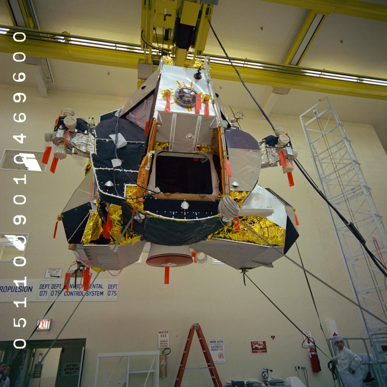
S69-19644 (4 Jan. 1969) --- Lunar Module (LM) 5 ascent stage in Final Assembly Area on overhead hoist being moved to dolly for roll-out inspection. LM-5 will be flown on the Apollo 11 lunar landing mission. Photo credit: NASA/Grumman
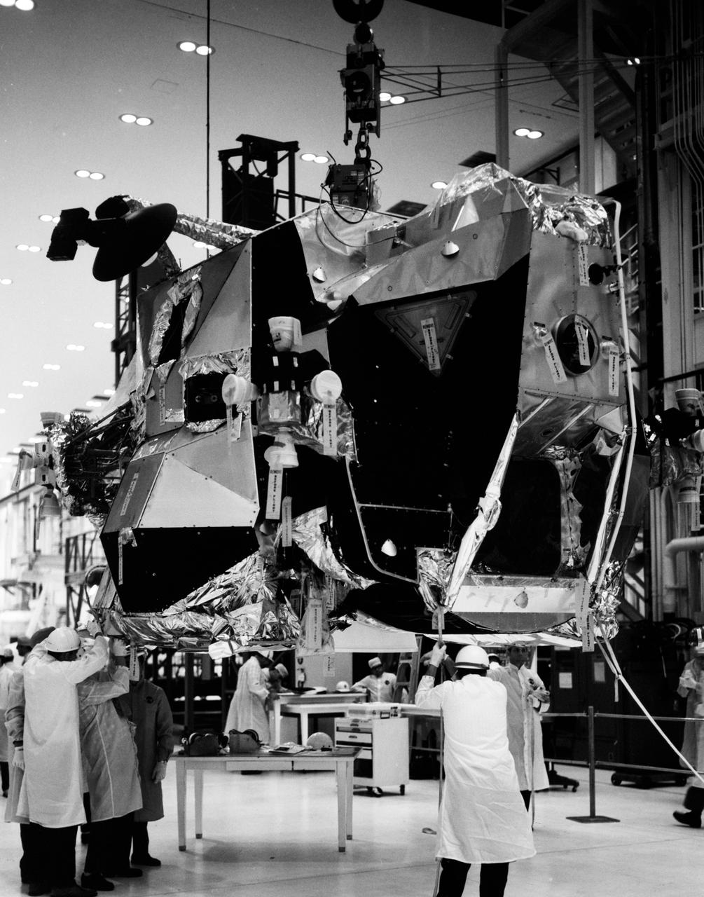
S69-25979 (December 1968) --- The ascent stage of Lunar Module-4 is moved from work stand into altitude chamber in the Kennedy Space Center's Manned Spacecraft Operations Building. Lunar Module-4 will be flown on the Apollo 10 (Spacecraft 106/Saturn 505) lunar orbit mission.
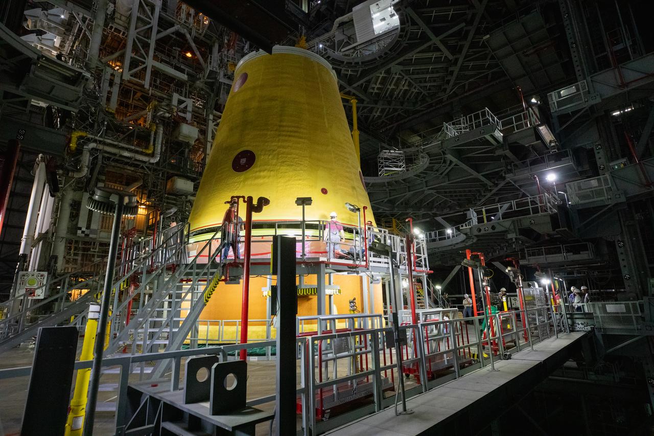
A massive crane lowers the launch vehicle stage adapter onto the SLS (Space Launch System) core stage on Thursday, April 3, 2025, in High Bay 3 inside the Vehicle Assembly Building at NASA’s Kennedy Space Center in Florida. During launch and ascent, the launch vehicle stage adapter provides structural support and protects avionics and electrical devices within the upper stage from extreme vibrations and acoustic conditions. The Artemis II test flight will take a crew of four astronauts on a 10-day journey around the Moon, helping confirm the foundational systems and hardware needed for human deep space exploration.

A massive crane lowers the launch vehicle stage adapter onto the SLS (Space Launch System) core stage on Thursday, April 3, 2025, in High Bay 3 inside the Vehicle Assembly Building at NASA’s Kennedy Space Center in Florida. During launch and ascent, the launch vehicle stage adapter provides structural support and protects avionics and electrical devices within the upper stage from extreme vibrations and acoustic conditions. The Artemis II test flight will take a crew of four astronauts on a 10-day journey around the Moon, helping confirm the foundational systems and hardware needed for human deep space exploration.
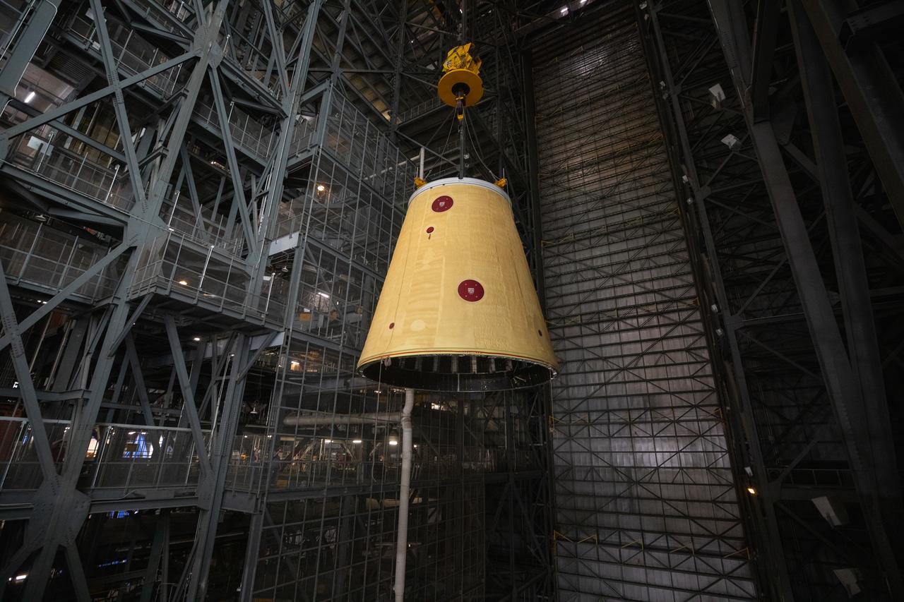
A massive crane lifts the launch vehicle stage adapter 250 feet into the air on Thursday, April 3, 2025, to prepare integration onto the SLS (Space Launch System) core stage in High Bay 3 inside the Vehicle Assembly Building at NASA’s Kennedy Space Center in Florida. During launch and ascent, the launch vehicle stage adapter provides structural support and protects avionics and electrical devices within the upper stage from extreme vibrations and acoustic conditions. The Artemis II test flight will take a crew of four astronauts on a 10-day journey around the Moon, helping confirm the foundational systems and hardware needed for human deep space exploration.
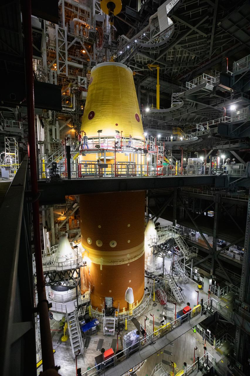
A massive crane lowers the launch vehicle stage adapter onto the SLS (Space Launch System) core stage on Thursday, April 3, 2025, in High Bay 3 inside the Vehicle Assembly Building at NASA’s Kennedy Space Center in Florida. During launch and ascent, the launch vehicle stage adapter provides structural support and protects avionics and electrical devices within the upper stage from extreme vibrations and acoustic conditions. The Artemis II test flight will take a crew of four astronauts on a 10-day journey around the Moon, helping confirm the foundational systems and hardware needed for human deep space exploration.
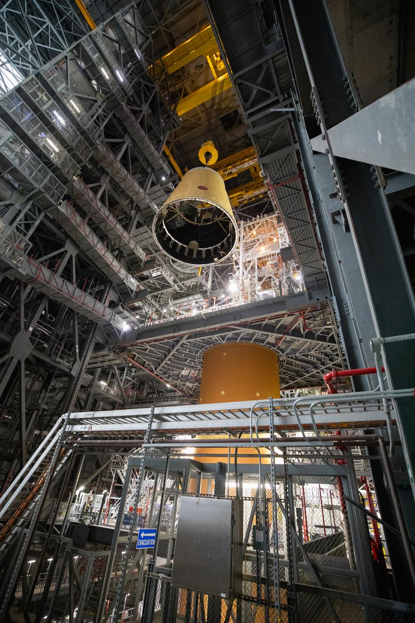
A massive crane lifts the launch vehicle stage adapter 250 feet into the air on Thursday, April 3, 2025, to prepare integration onto the SLS (Space Launch System) core stage in High Bay 3 inside the Vehicle Assembly Building at NASA’s Kennedy Space Center in Florida. During launch and ascent, the launch vehicle stage adapter provides structural support and protects avionics and electrical devices within the upper stage from extreme vibrations and acoustic conditions. The Artemis II test flight will take a crew of four astronauts on a 10-day journey around the Moon, helping confirm the foundational systems and hardware needed for human deep space exploration.
A massive crane lifts the launch vehicle stage adapter 250 feet into the air on Thursday, April 3, 2025, to prepare integration onto the SLS (Space Launch System) core stage in High Bay 3 inside the Vehicle Assembly Building at NASA’s Kennedy Space Center in Florida. During launch and ascent, the launch vehicle stage adapter provides structural support and protects avionics and electrical devices within the upper stage from extreme vibrations and acoustic conditions. The Artemis II test flight will take a crew of four astronauts on a 10-day journey around the Moon, helping confirm the foundational systems and hardware needed for human deep space exploration.
A massive crane lifts the launch vehicle stage adapter 250 feet into the air on Thursday, April 3, 2025, to prepare integration onto the SLS (Space Launch System) core stage in High Bay 3 inside the Vehicle Assembly Building at NASA’s Kennedy Space Center in Florida. During launch and ascent, the launch vehicle stage adapter provides structural support and protects avionics and electrical devices within the upper stage from extreme vibrations and acoustic conditions. The Artemis II test flight will take a crew of four astronauts on a 10-day journey around the Moon, helping confirm the foundational systems and hardware needed for human deep space exploration.
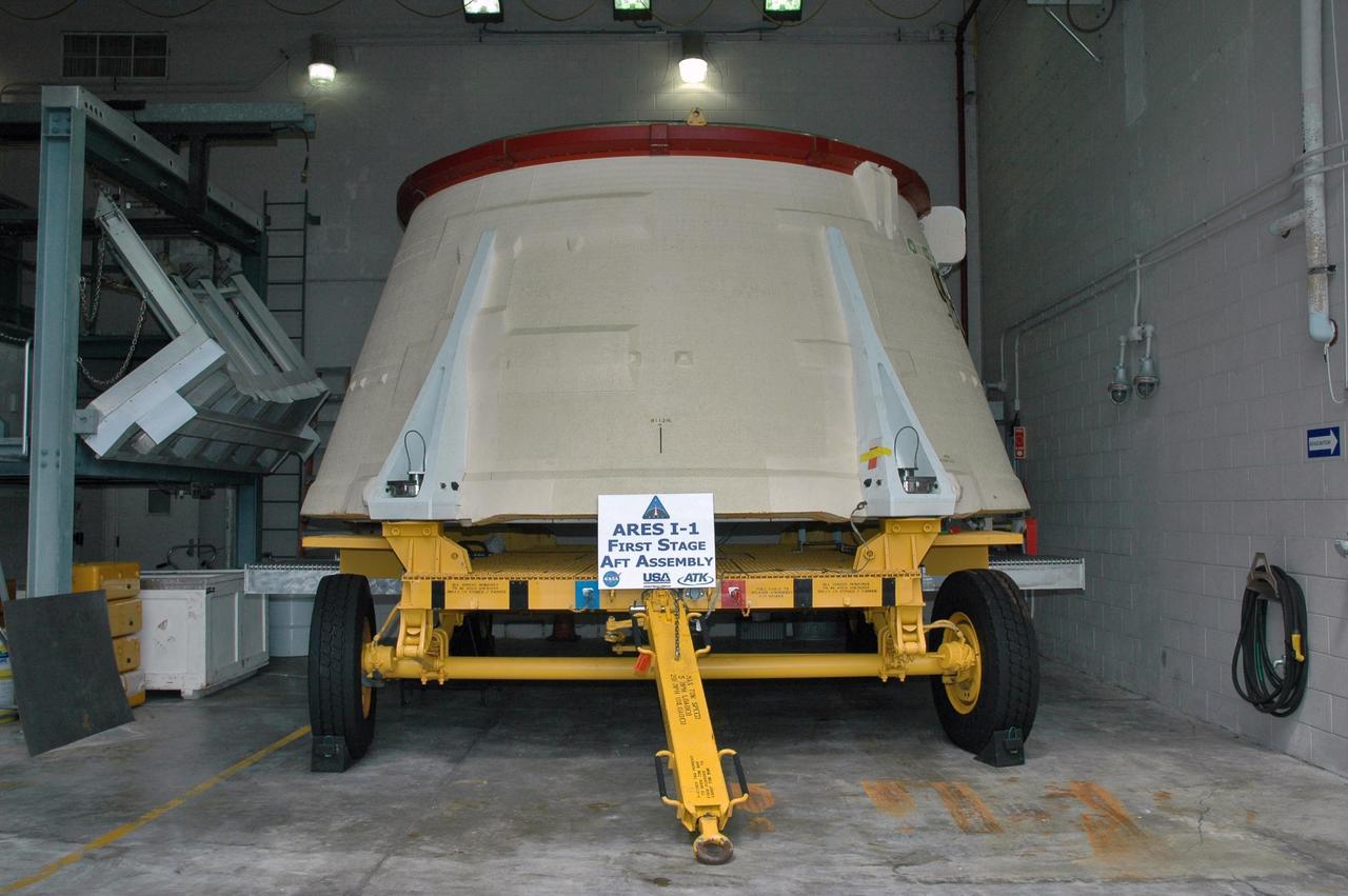
KENNEDY SPACE CENTER, FLA. - In the Assembly and Refurbishment Facility at NASA's Kennedy Space Center, the solid rocket booster aft skirt designated for use on the first stage of the ARES I-1 launch vehicle is being prepared for its first test flight. Ares I is the vehicle being developed for launch of the crew exploration vehicle (CEV), named Orion. Ares I-1 is currently targeted for launch from Launch Pad 39B in 2009 using the SRB first stage and a simulated second stage and simulated CEV. Ares I ascent tests and Ares I orbital tests will also take place at Kennedy at later dates. Photo credit: NASA/Jack Pfaller
S72-35614 (23 April 1972) --- The Apollo 16 Lunar Module "Orion" ascent stage makes its liftoff from the lunar surface in this reproduction taken from a color television transmission made by the RCA color TV camera mounted on the Lunar Roving Vehicle (LRV). Remotely controlled from NASA's Mission Control Center (MCC) in Houston, the LRV-mounted camera made it possible for persons on Earth to watch the LM's launch from the moon. Liftoff occurred at 175:44 ground elapsed time, 7:26 p.m. (CST), April 23, 1972. The "Orion" ascent stage, with astronauts John W. Young and Charles M. Duke Jr. aboard, returned from the lunar surface to rejoin the Command and Service Modules (CSM) orbiting the moon. Astronaut Thomas K. (Ken) Mattingly II remained with the CSM in lunar orbit while Young and Duke descended in the LM to explore the Descartes landing site. The LM descent stage is used as a launching platform and remains behind on the moon.
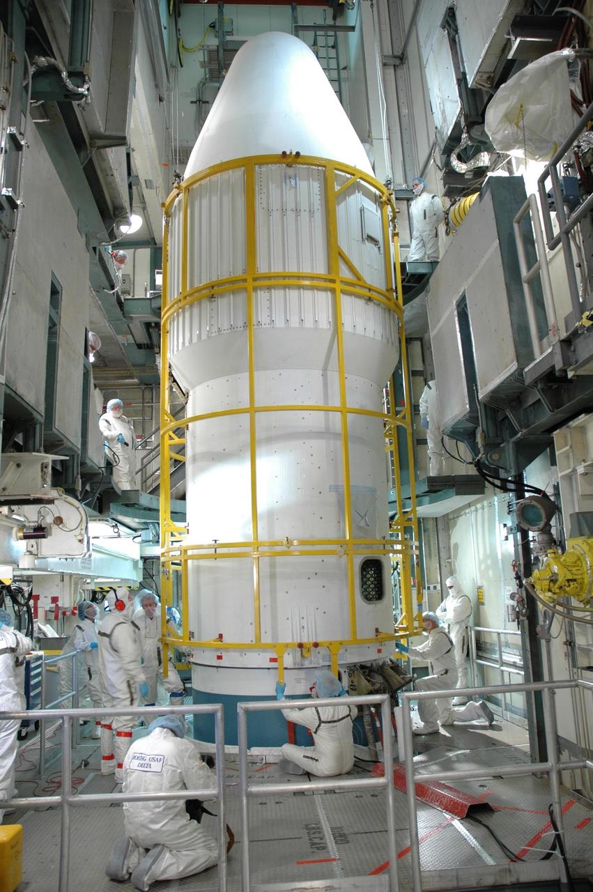
KENNEDY SPACE CENTER, FLA. -- Inside the mobile service tower on Launch Pad 17-B at Cape Canaveral Air Force Station, technicians secure both halves of the fairing around the Dawn spacecraft to the upper stage booster of the Delta II rocket below. The fairing is a molded structure that fits flush with the outside surface of the Delta II upper stage booster and forms an aerodynamically smooth nose cone, protecting the spacecraft during launch and ascent. Dawn is scheduled to launch between 7:25 and 7:54 a.m. on Sept. 26 aboard a Delta II rocket. Photo credit: NASA/Jim Grossmann
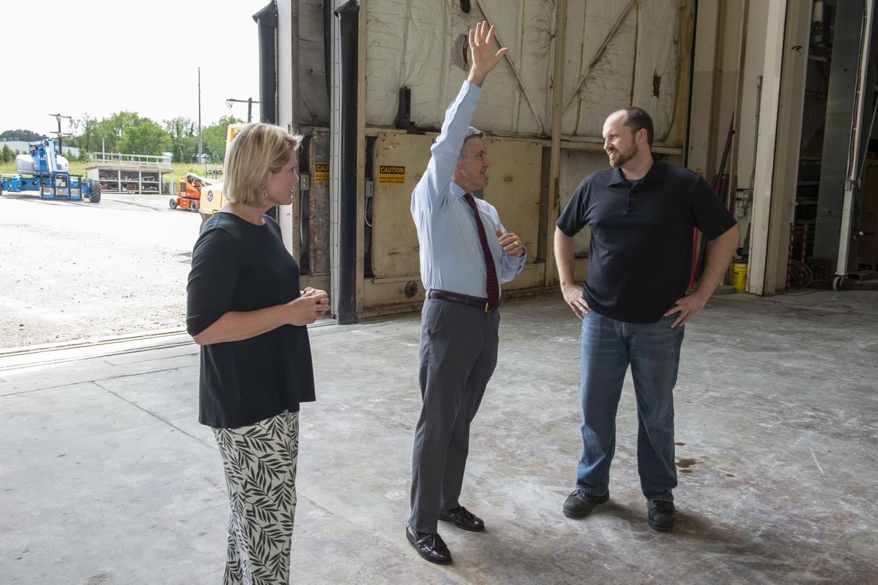
Kennedy Space Center Director Robert Cabana, center, receives an update on SLS hardware from Heather Haney, left, an engineer in the Space Launch System stages office, and Mark White, lead test engineer for the SLS core stage engine section, on July 16 in Marshall's Building 4619. Cabana, Haney and White are standing in front of a structural test version of the Intertank, the 212-foot-tall backbone of the SLS rocket. The structural test article is undergoing critical testing as engineers push, pull and bend the hardware with millions of pounds of force to ensure it can withstand the forces of launch and ascent.

S68-19459 (22 Jan. 1968) --- The Apollo 5 (LM-1/Saturn 204) unmanned space mission was launched from the Kennedy Space Center's Launch Complex 37 at 5:48:09 p.m. (EST), Jan. 22, 1968. The Lunar Module-1 payload was boosted into Earth orbit by a launch vehicle composed of a Saturn IB first stage and a Saturn S-IVB second stage. The Apollo lunar module's first flight test was called a complete success. Ascent and descent propulsion systems and the ability to abort a lunar landing and return to orbit were demonstrated.

S68-19460 (22 Jan. 1968) --- The Apollo 5 (LM-1/Saturn 204) unmanned space mission was launched from the Kennedy Space Center's Launch Complex 37 at 5:48:09 p.m. (EST), Jan. 22, 1968. The Lunar Module-1 payload was boosted into Earth orbit by a launch vehicle composed of a Saturn IB first stage and a Saturn S-IVB second stage. The Apollo lunar module's first flight test was called a complete success. Ascent and descent propulsion systems and the ability to abort a lunar landing and return to orbit were demonstrated.
S69-32396 (4 April 1969) --- Interior view of the Kennedy Space Center's (KSC) Manned Spacecraft Operations Building showing Lunar Module (LM) 5 being moved from work stand for mating with its Spacecraft Lunar Module Adapter (SLA). LM-5 is scheduled to be flown on the Apollo 11 lunar landing mission.
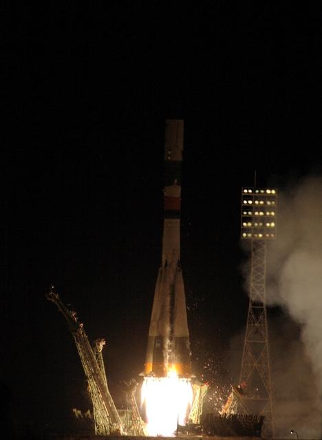
JSC2007-E-41113(2 Aug. 2007) --- The ISS Progress 26 launched Aug. 2 from the Baikonur Cosmodrome in Kazakhstan on time at 12:33:46 pm (CDT) and 11:33:46 pm, Baikonur time. Ascent was nominal and by the book. Once in orbit, the Progress separated from the third stage of the booster and all appendages and antennas were deployed on time. Photo Credit: NASA/Mark Bowman

AS-204, the fourth Saturn IB launch vehicle, developed by the Marshall Space Flight Center (MSFC), awaits its January 22, 1968 liftoff from Cape Canaveral, Florida for the unmarned Apollo 5 mission. Primary mission objectives included the verification of the Apollo Lunar Module's (LM) ascent and descent propulsion systems and an evaluation of the S-IVB stage instrument unit performance. In all, nine Saturn IB flights were made, ending with the Apollo-Soyuz Test Project in July 1975.
JOHNSON SPACE CENTER, HOUSTON, TEXAS - With a half-Earth in the background, the Lunar Module ascent stage with Moon-walking astronauts Neil Armstrong and Edwin Aldrin Jr. approaches for a rendezvous with the Apollo Command Module manned by Michael Collins. The Apollo 11 liftoff from the Moon came early, ending a 22-hour stay on the Moon by Armstrong and Aldrin.
AS16-122-19527 (23 April 1972) --- The Apollo 16 Lunar Module (LM) ascent stage, with astronauts John W. Young and Charles M. Duke Jr. aboard, returns from the lunar surface to rejoin the Command and Service Modules (CSM) in lunar orbit. Astronaut Thomas K. (Ken) Mattingly II took this photograph from the Command Module (CM). The LM is above the Crater Schubert B. The lunar surface area visible in this picture is located at the western edge of Smyth's Sea.
KENNEDY SPACE CENTER, FLA. -- Inside the mobile service tower on Launch Pad 17-B at Cape Canaveral Air Force Station, the Dawn spacecraft is ready for installation of the fairing. The fairing is a molded structure that fits flush with the outside surface of the Delta II upper stage booster and forms an aerodynamically smooth nose cone, protecting the spacecraft during launch and ascent. Dawn is scheduled to launch between 7:25 and 7:54 a.m. on Sept. 26 aboard a Delta II rocket. Photo credit: NASA/Jim Grossmann
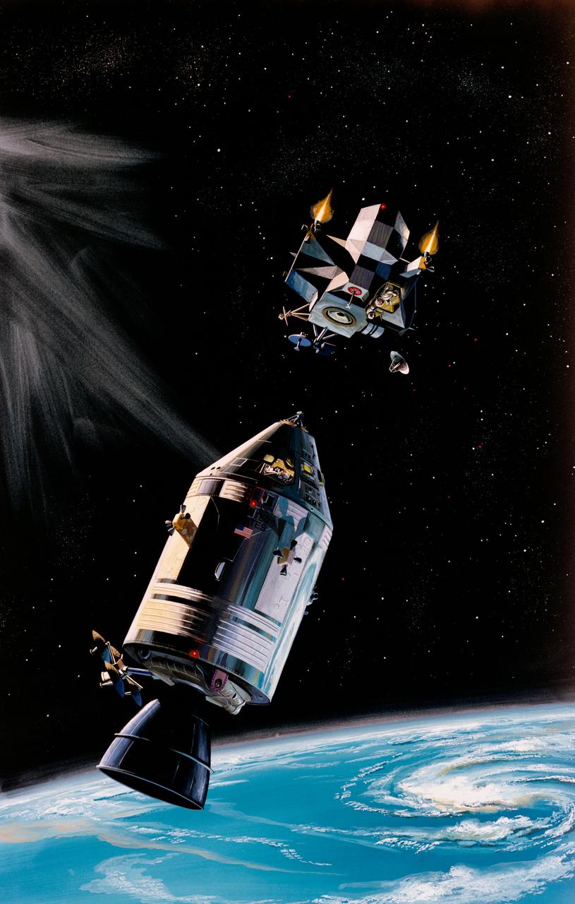
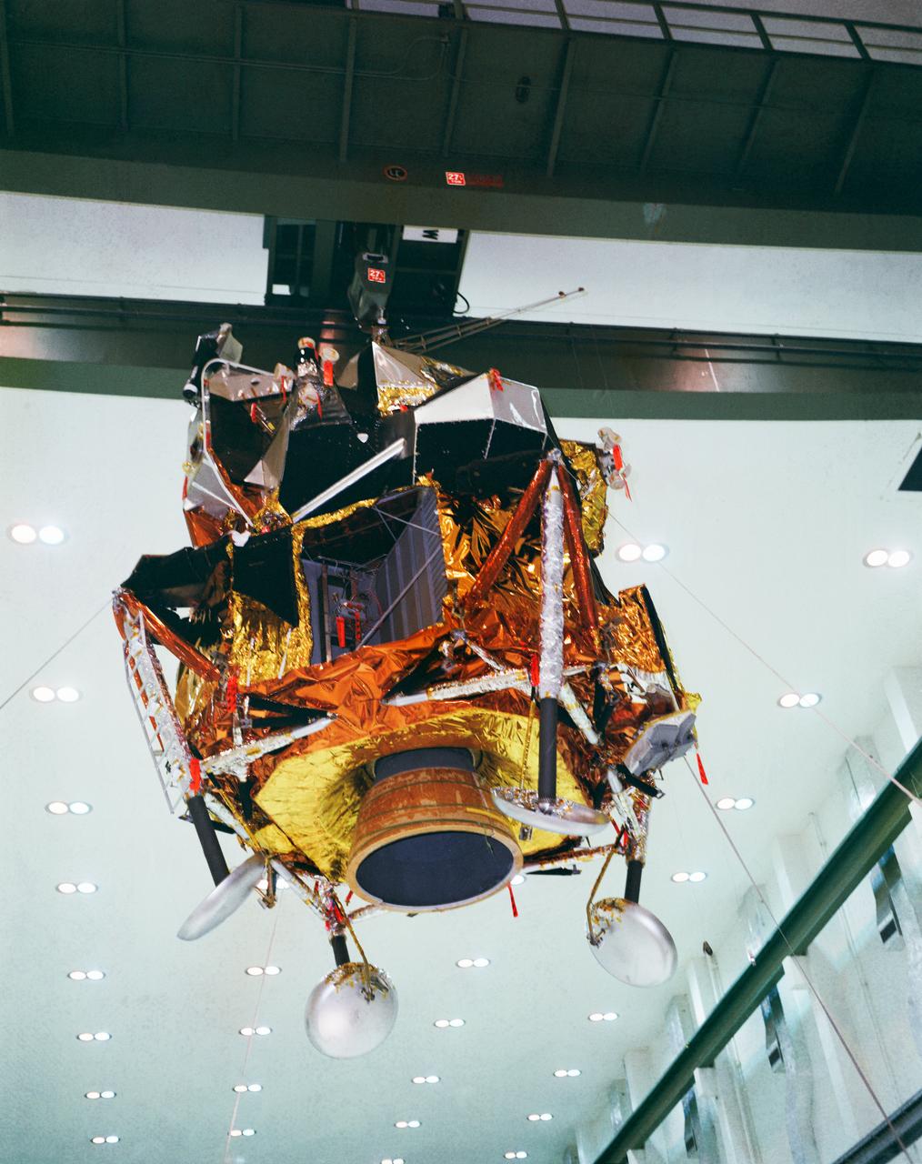
S69-18546 (February 1969) --- North American Rockwell artist's concept illustrating the docking of the Lunar Module ascent stage with the Command and Service Modules during the Apollo 9 mission. The two figures in the Lunar Module represent astronauts James A. McDivitt, Apollo 9 commander; and Russell L. Schweickart, lunar module pilot. The figure in the Command Module represents astronaut David R. Scott, command module pilot. The Apollo 9 mission will evaluate spacecraft lunar module systems performance during manned Earth-orbital flight.
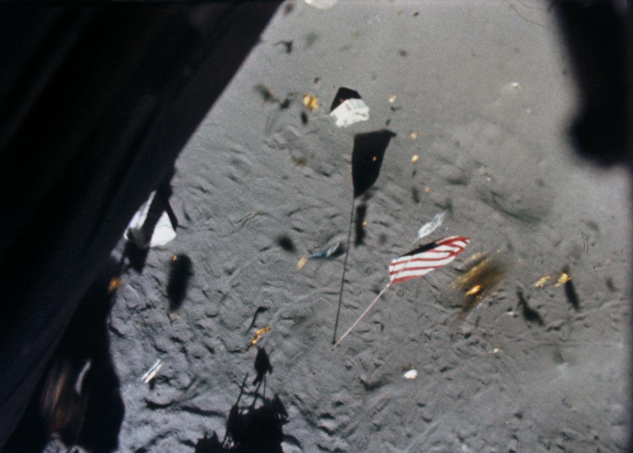
S71-19500 (6 Feb. 1971) --- The Apollo 14 Lunar Module (LM) ascent stage lifts off the lunar surface and the powerful LM engine causes a brief force of wind which scatters gold-colored foil, covering the LM, and disturbs the U.S. flag. This picture was taken from film exposed by the 16mm data acquisition camera - which was mounted inside the LM.
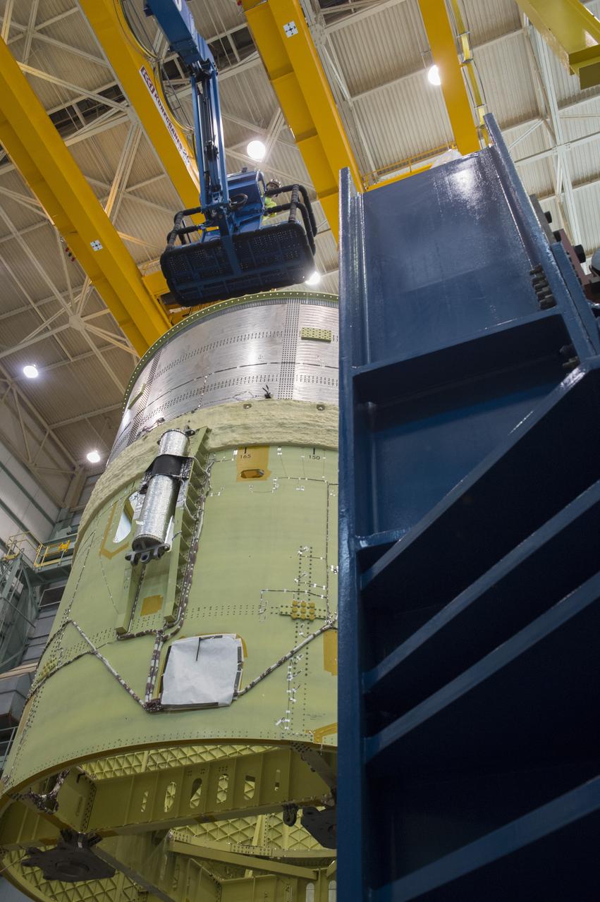
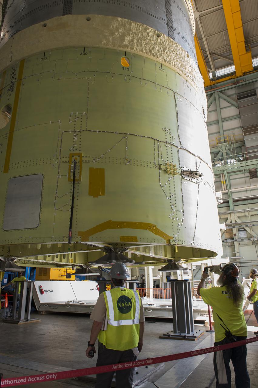
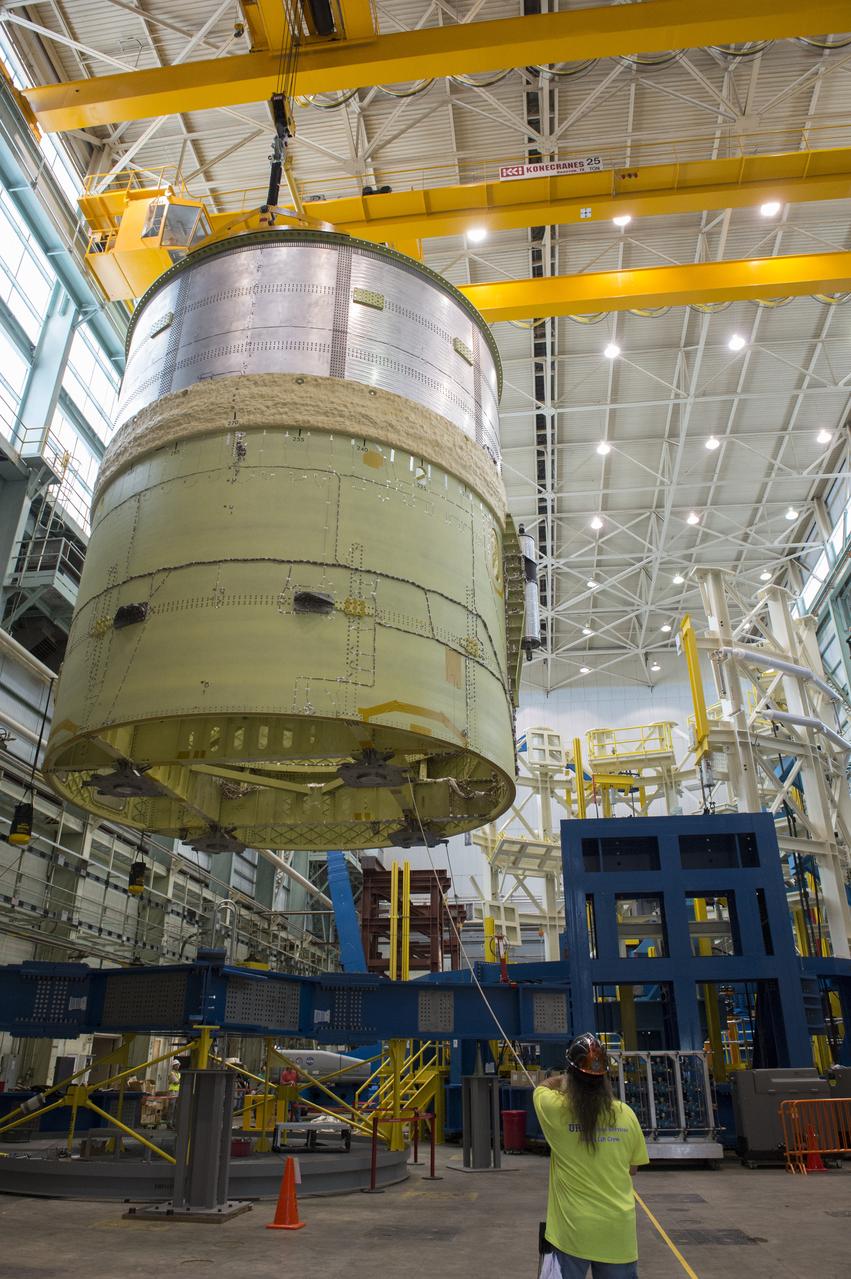
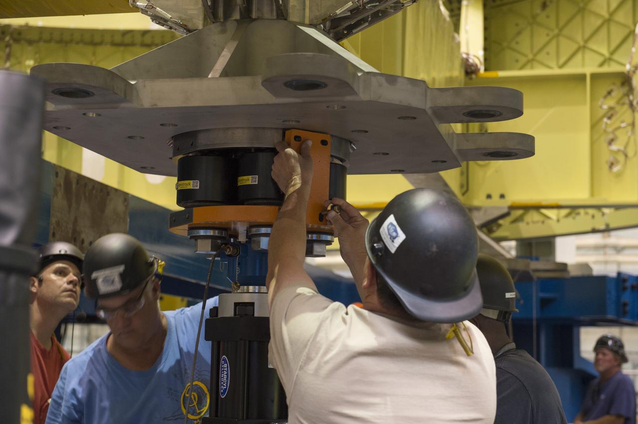
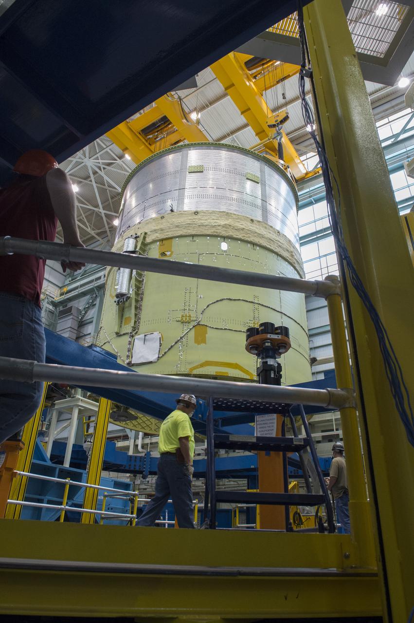
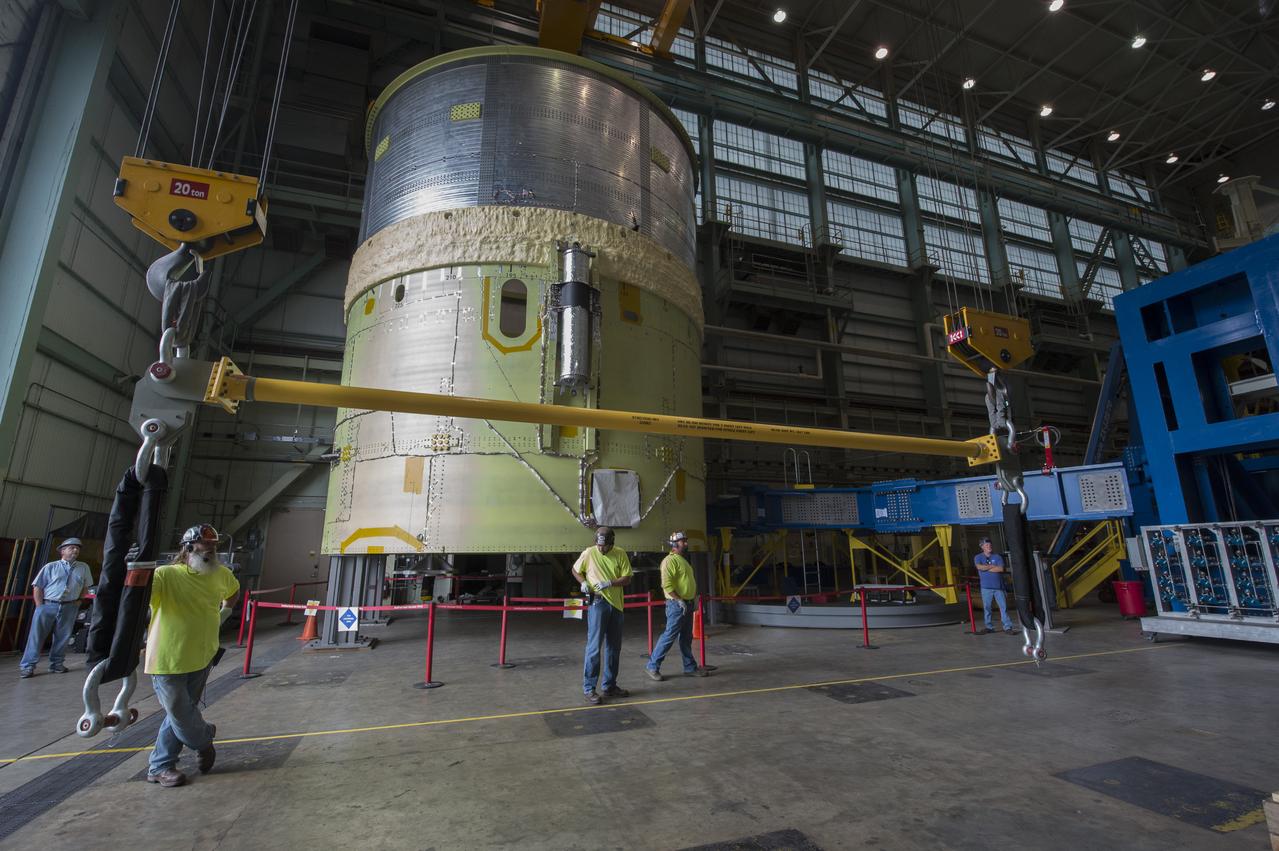
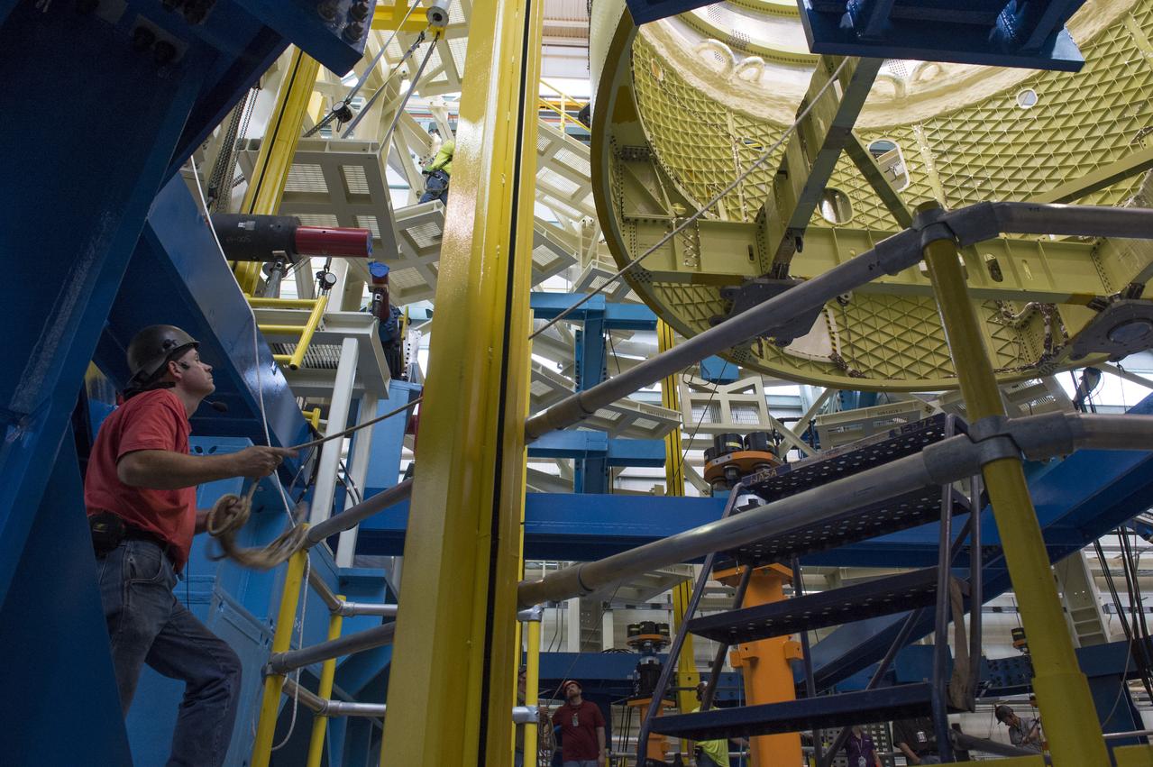
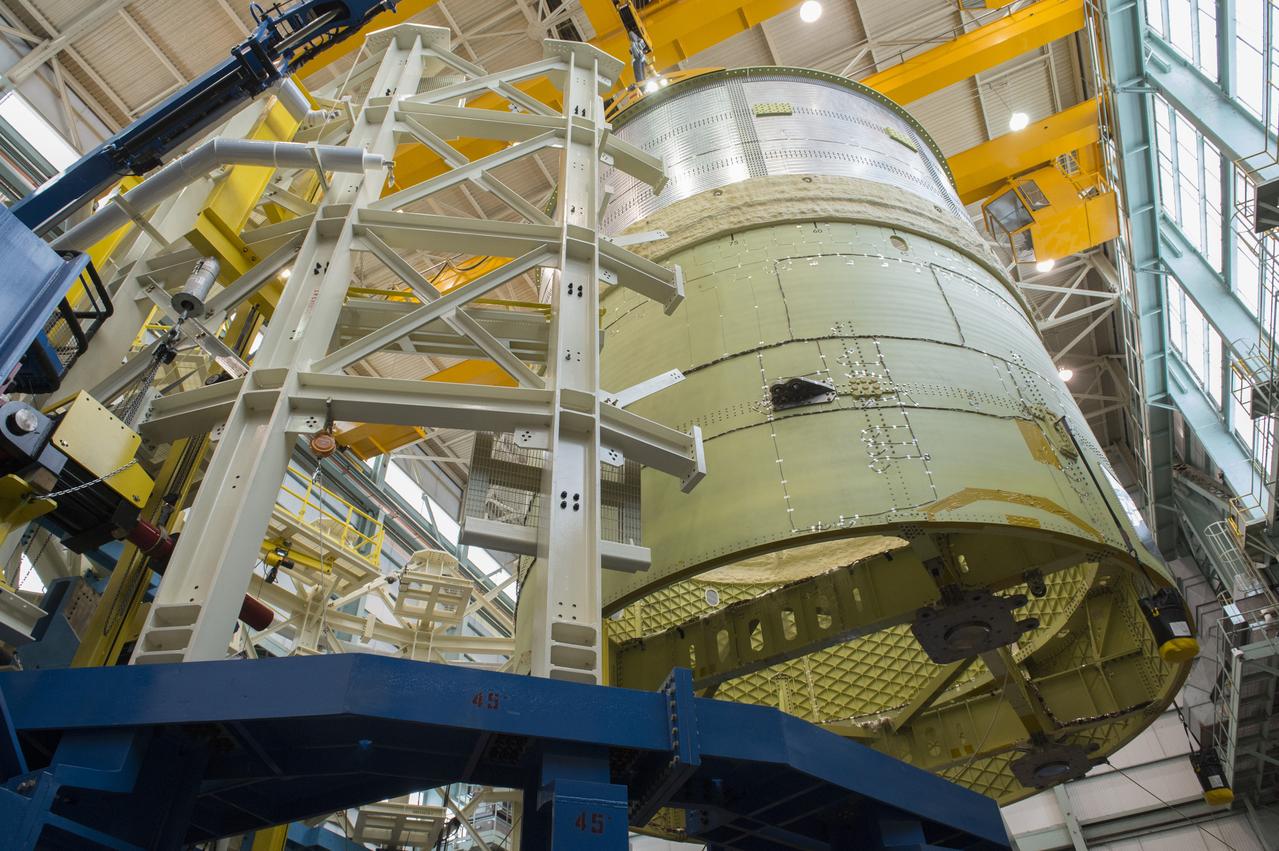
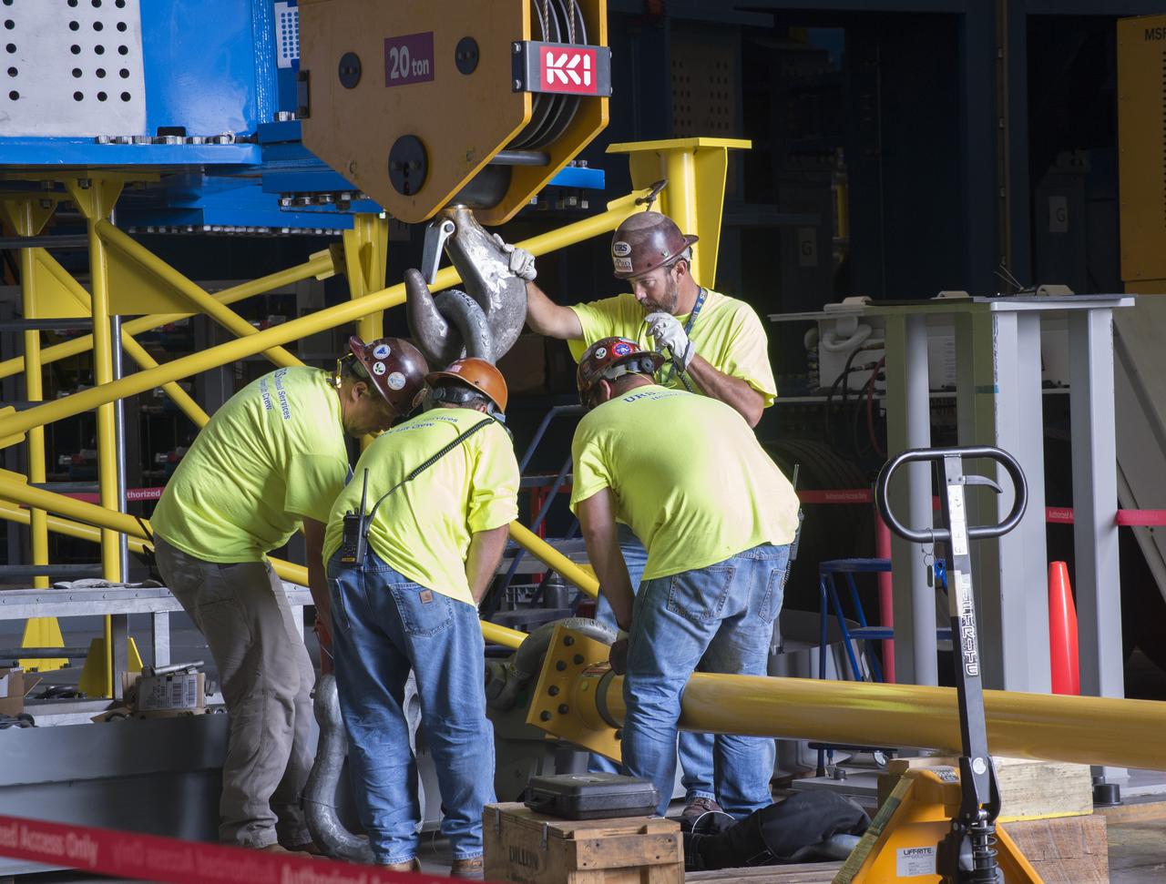
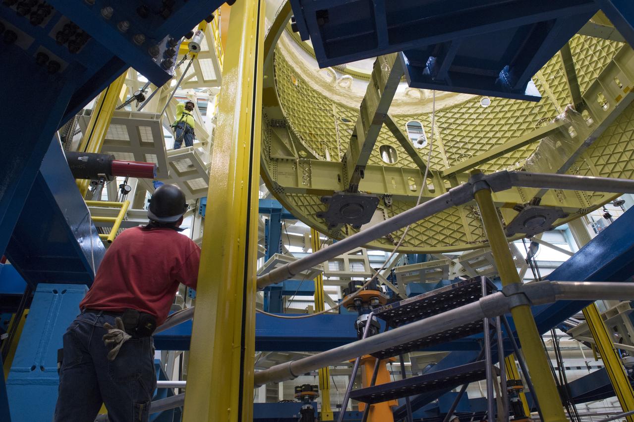
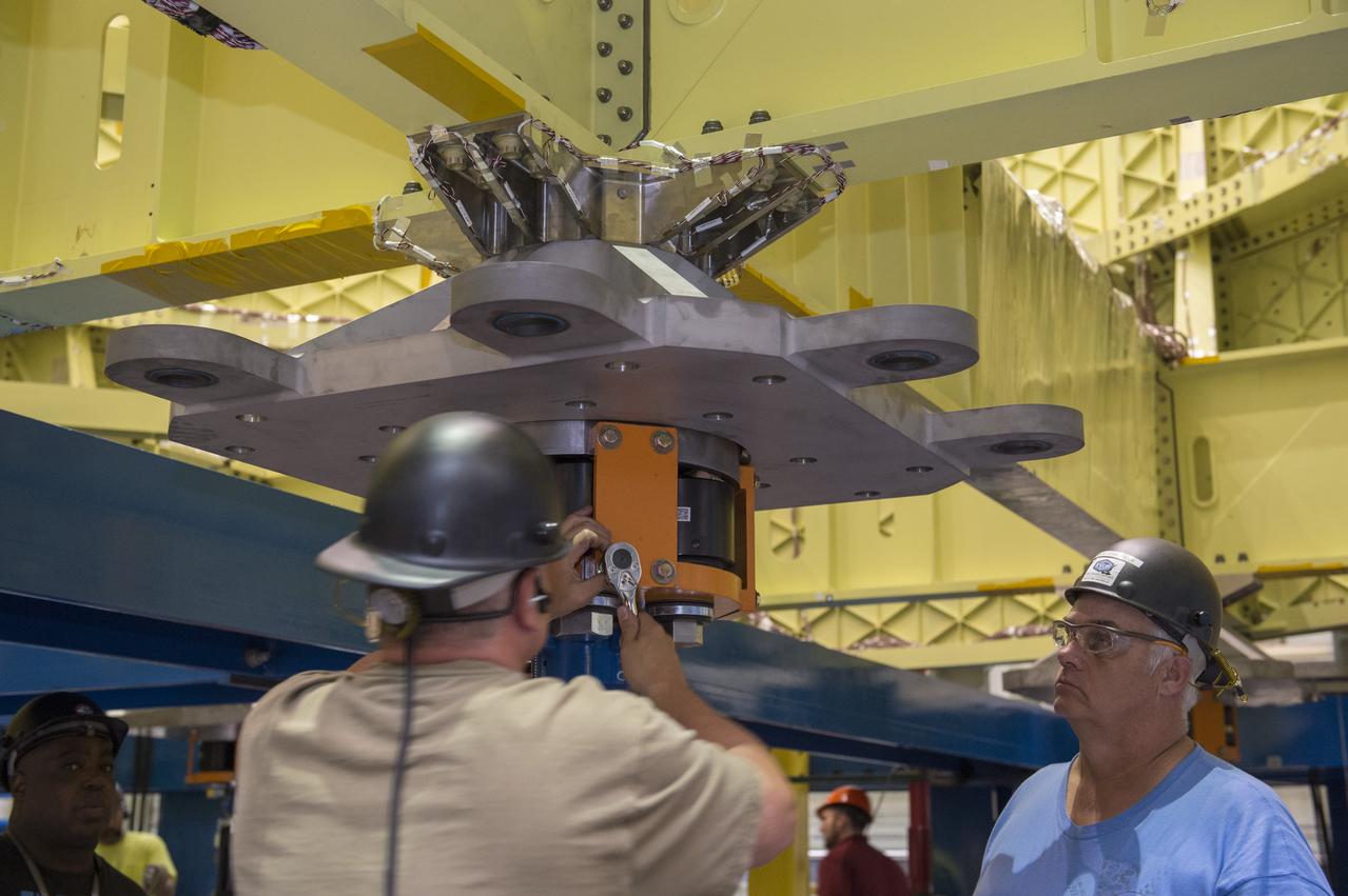
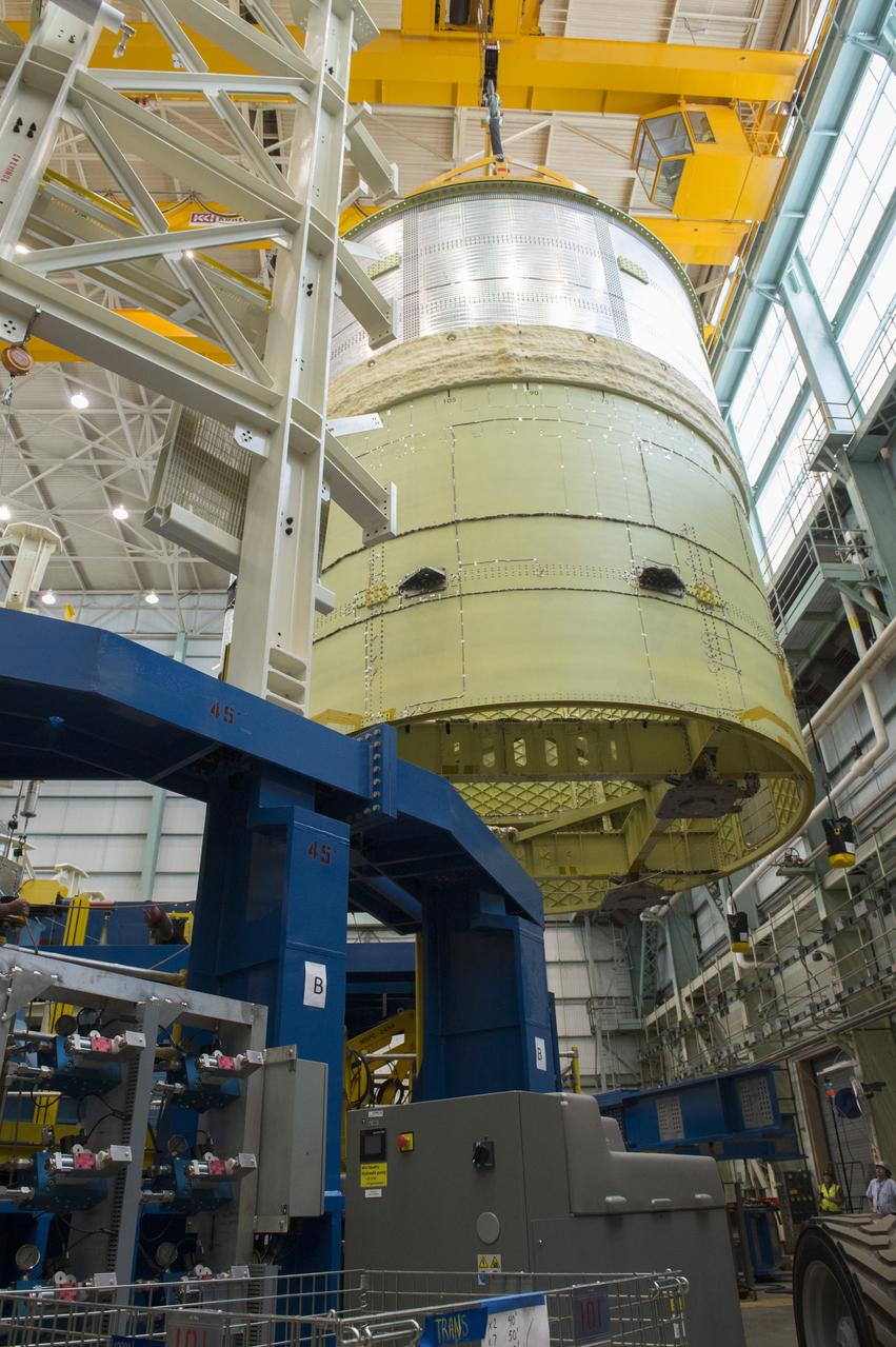
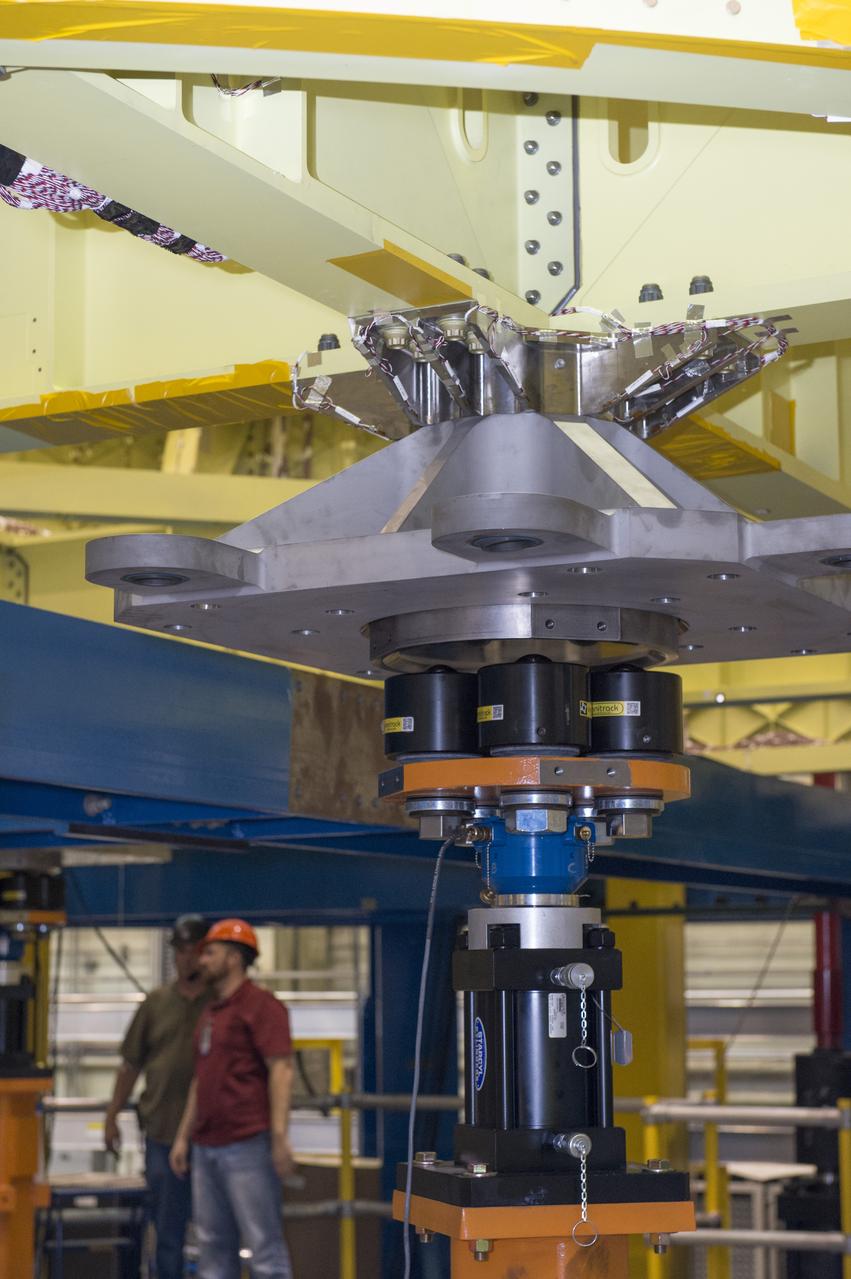
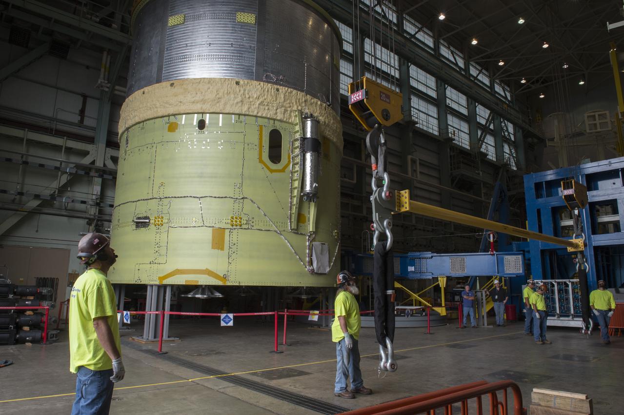
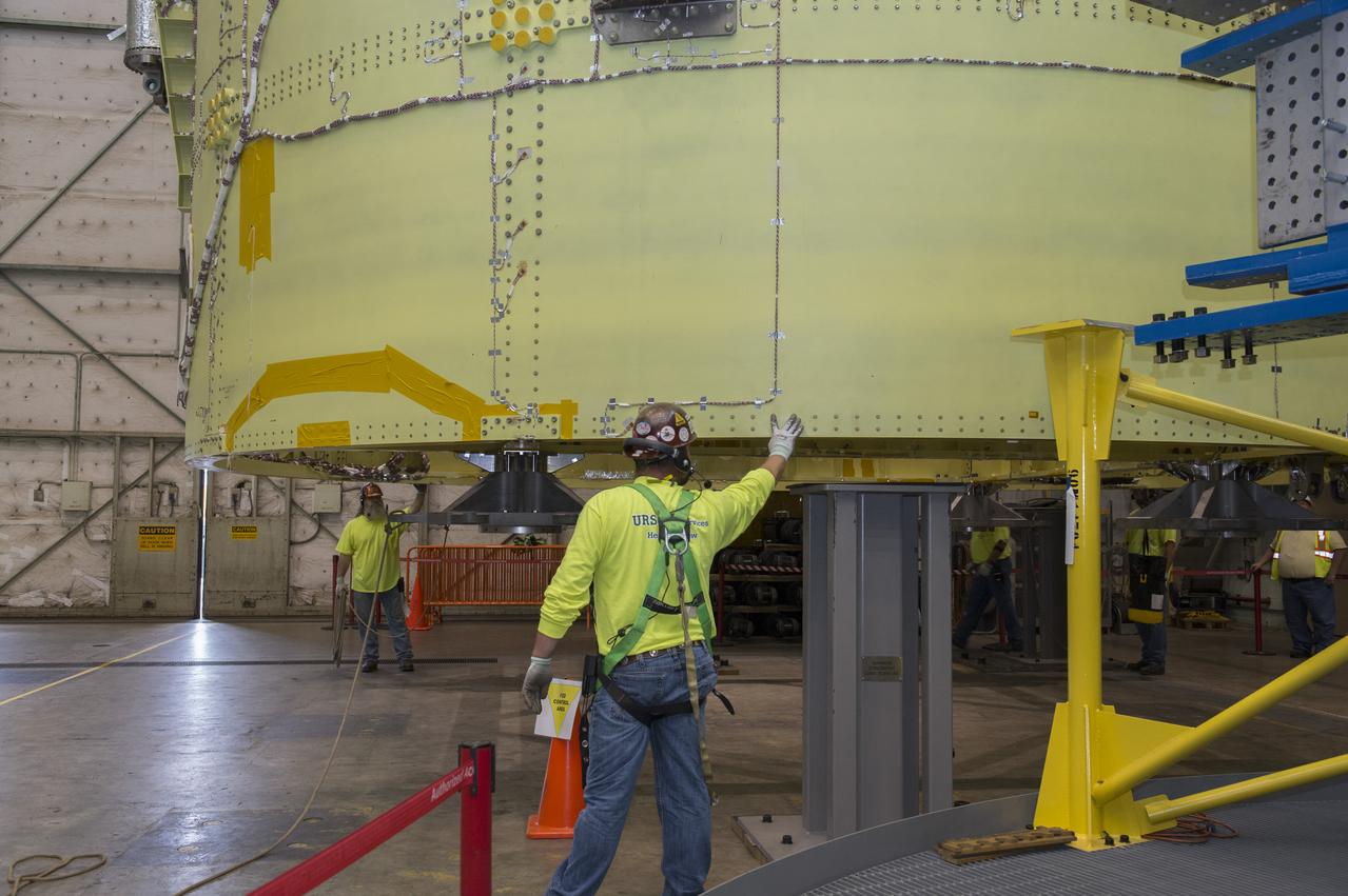
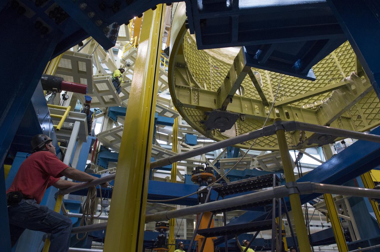
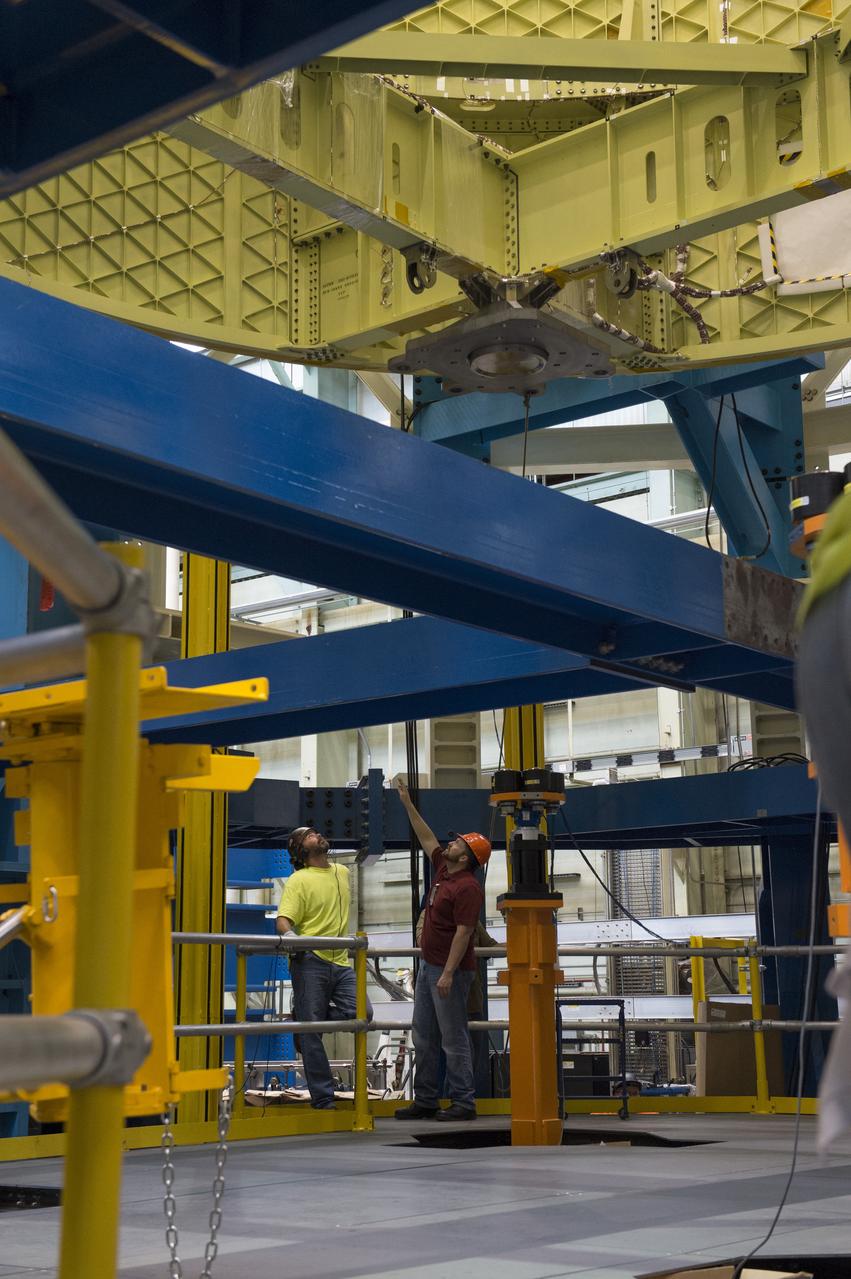
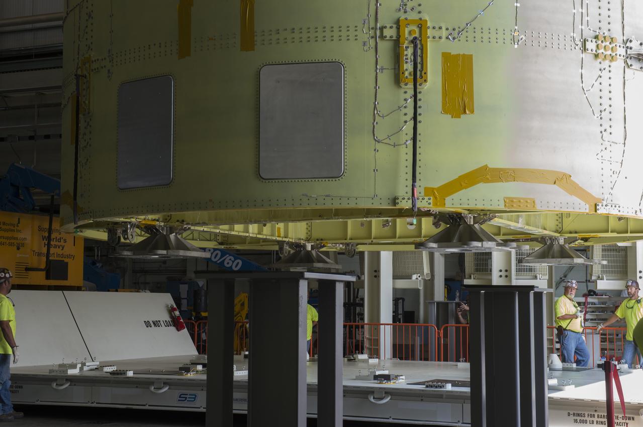
NASA engineers install test hardware for the agency's new heavy lift rocket, the Space Launch System, into a newly constructed 50-foot structural test stand at NASA's Marshall Space Flight Center. In the stand, hydraulic cylinders will be electronically controlled to push, pull, twist and bend the test article with millions of pounds of force. Engineers will record and analyze over 3,000 channels of data for each test case to verify the capabilities of the engine section and validate that the design and analysis models accurately predict the amount of loads the core stage can withstand during launch and ascent. The engine section, recently delivered via NASA's barge Pegasus from NASA's Michoud Assembly Facility, is the first of four core stage structural test articles scheduled to be delivered to Marshall for testing. The engine section, located at the bottom of SLS's massive core stage, will house the rocket's four RS-25 engines and be an attachment point for the two solid rocket boosters.
NASA engineers install test hardware for the agency's new heavy lift rocket, the Space Launch System, into a newly constructed 50-foot structural test stand at NASA's Marshall Space Flight Center. In the stand, hydraulic cylinders will be electronically controlled to push, pull, twist and bend the test article with millions of pounds of force. Engineers will record and analyze over 3,000 channels of data for each test case to verify the capabilities of the engine section and validate that the design and analysis models accurately predict the amount of loads the core stage can withstand during launch and ascent. The engine section, recently delivered via NASA's barge Pegasus from NASA's Michoud Assembly Facility, is the first of four core stage structural test articles scheduled to be delivered to Marshall for testing. The engine section, located at the bottom of SLS's massive core stage, will house the rocket's four RS-25 engines and be an attachment point for the two solid rocket boosters.
NASA engineers install test hardware for the agency's new heavy lift rocket, the Space Launch System, into a newly constructed 50-foot structural test stand at NASA's Marshall Space Flight Center. In the stand, hydraulic cylinders will be electronically controlled to push, pull, twist and bend the test article with millions of pounds of force. Engineers will record and analyze over 3,000 channels of data for each test case to verify the capabilities of the engine section and validate that the design and analysis models accurately predict the amount of loads the core stage can withstand during launch and ascent. The engine section, recently delivered via NASA's barge Pegasus from NASA's Michoud Assembly Facility, is the first of four core stage structural test articles scheduled to be delivered to Marshall for testing. The engine section, located at the bottom of SLS's massive core stage, will house the rocket's four RS-25 engines and be an attachment point for the two solid rocket boosters.
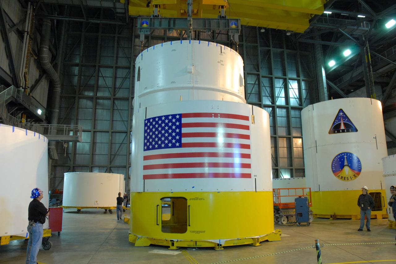
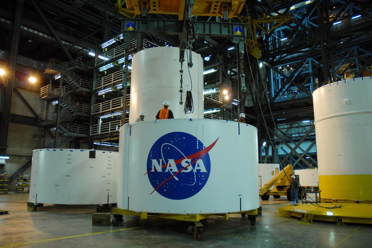
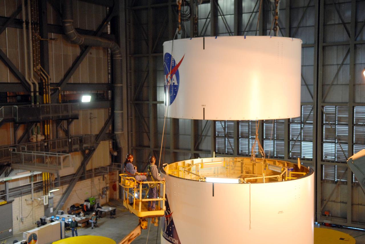
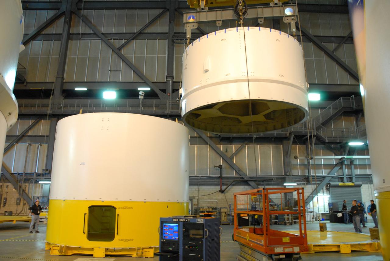
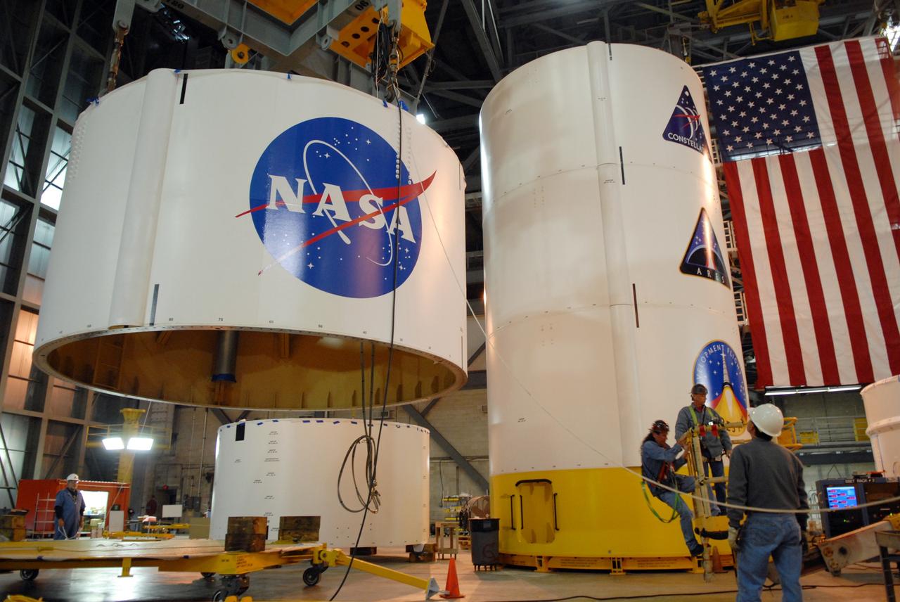
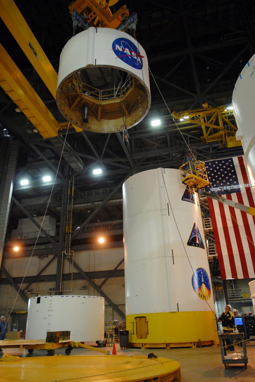
CAPE CANAVERAL, Fla. -- In high bay 4 of the Vehicle Assembly Building at NASA's Kennedy Space Center in Florida, a crane moves the Ares I-X upper stage simulator segment 7 toward segment 6 (in front, with U.S. flag decal). The upper stage simulator comprises 11 segments, each approximately 18 feet in diameter, that will be used in the test flight identified as Ares I-X in 2009. The simulator segments will simulate the mass and the outer mold line. The upper stage accounts for nearly one-quarter of the total height of the Ares I. It will take the Ares I on the second phase of its journey from Earth, providing the guidance, navigation and control needed for the second phase of the Ares I ascent flight. Photo credit: NASA/Kim Shiflett
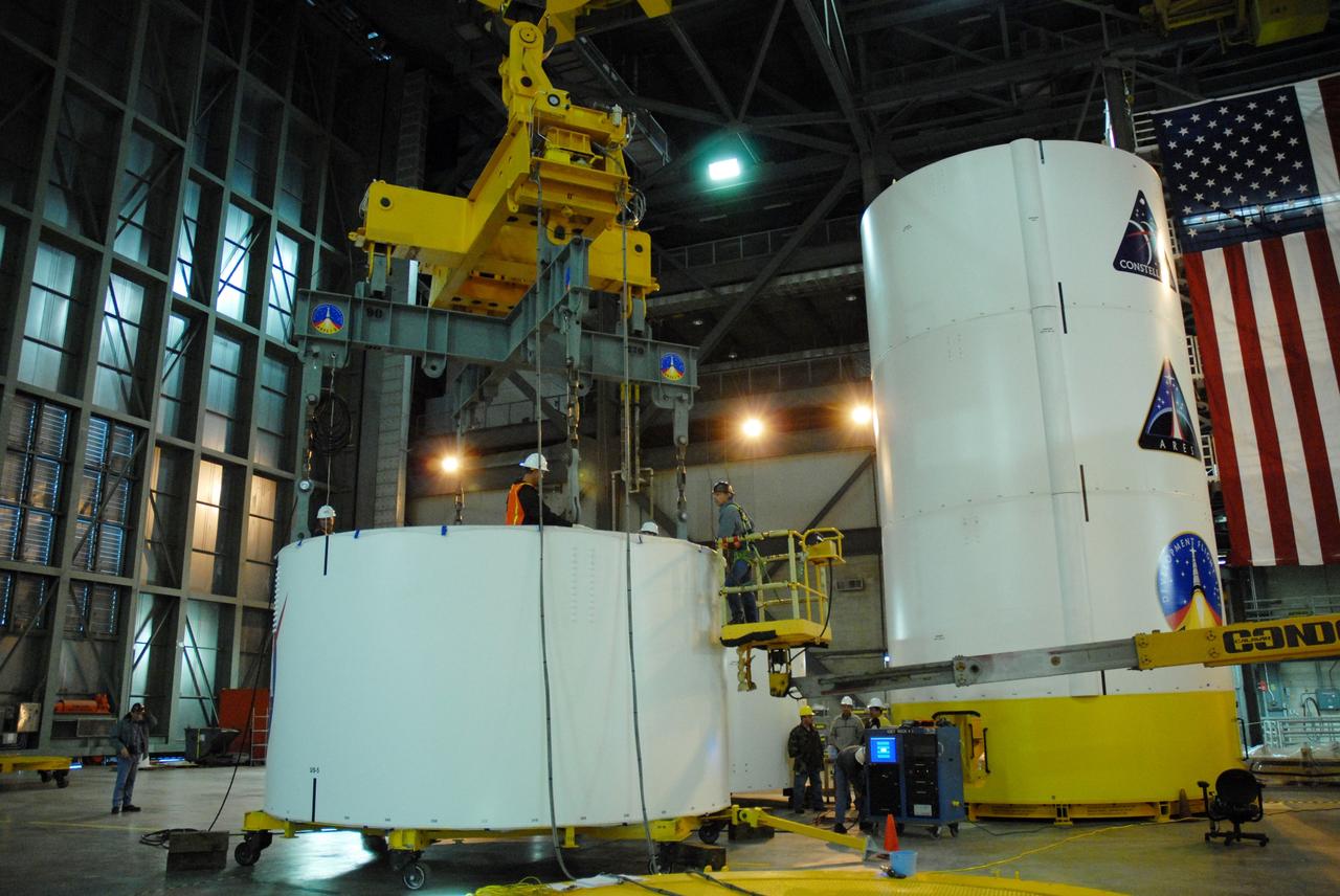
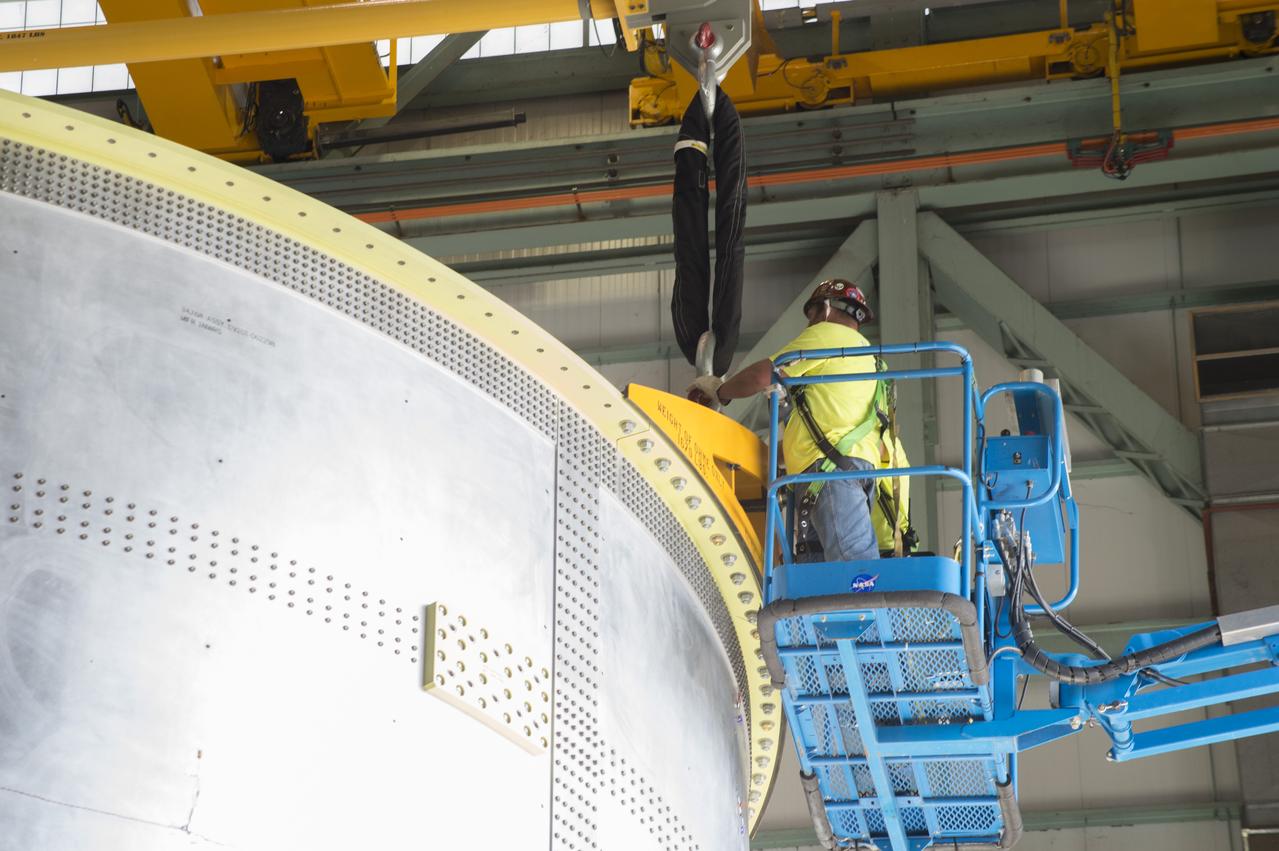
CAPE CANAVERAL, Fla. -- In high bay 4 of the Vehicle Assembly Building at NASA's Kennedy Space Center in Florida, a crane is attached to segment 5 of the Ares I-X upper stage simulator segments to lift it. Segment 5 will be stacked on to segment 4, at the top of the tall stack at right.The upper stage simulator comprises 11 segments, each approximately 18 feet in diameter, that will be used in the test flight known as Ares I-X in 2009. The simulator segments will simulate the mass and the outer mold line. The upper stage accounts for nearly one-quarter of the total height of the Ares I. It will take the Ares I on the second phase of its journey from Earth, providing the guidance, navigation and control needed for the second phase of the Ares I ascent flight. Photo credit: NASA/Jim Grossmann
NASA engineers install test hardware for the agency's new heavy lift rocket, the Space Launch System, into a newly constructed 50-foot structural test stand at NASA's Marshall Space Flight Center. In the stand, hydraulic cylinders will be electronically controlled to push, pull, twist and bend the test article with millions of pounds of force. Engineers will record and analyze over 3,000 channels of data for each test case to verify the capabilities of the engine section and validate that the design and analysis models accurately predict the amount of loads the core stage can withstand during launch and ascent. The engine section, recently delivered via NASA's barge Pegasus from NASA's Michoud Assembly Facility, is the first of four core stage structural test articles scheduled to be delivered to Marshall for testing. The engine section, located at the bottom of SLS's massive core stage, will house the rocket's four RS-25 engines and be an attachment point for the two solid rocket boosters.
NASA engineers install test hardware for the agency's new heavy lift rocket, the Space Launch System, into a newly constructed 50-foot structural test stand at NASA's Marshall Space Flight Center. In the stand, hydraulic cylinders will be electronically controlled to push, pull, twist and bend the test article with millions of pounds of force. Engineers will record and analyze over 3,000 channels of data for each test case to verify the capabilities of the engine section and validate that the design and analysis models accurately predict the amount of loads the core stage can withstand during launch and ascent. The engine section, recently delivered via NASA's barge Pegasus from NASA's Michoud Assembly Facility, is the first of four core stage structural test articles scheduled to be delivered to Marshall for testing. The engine section, located at the bottom of SLS's massive core stage, will house the rocket's four RS-25 engines and be an attachment point for the two solid rocket boosters.
NASA engineers install test hardware for the agency's new heavy lift rocket, the Space Launch System, into a newly constructed 50-foot structural test stand at NASA's Marshall Space Flight Center. In the stand, hydraulic cylinders will be electronically controlled to push, pull, twist and bend the test article with millions of pounds of force. Engineers will record and analyze over 3,000 channels of data for each test case to verify the capabilities of the engine section and validate that the design and analysis models accurately predict the amount of loads the core stage can withstand during launch and ascent. The engine section, recently delivered via NASA's barge Pegasus from NASA's Michoud Assembly Facility, is the first of four core stage structural test articles scheduled to be delivered to Marshall for testing. The engine section, located at the bottom of SLS's massive core stage, will house the rocket's four RS-25 engines and be an attachment point for the two solid rocket boosters.
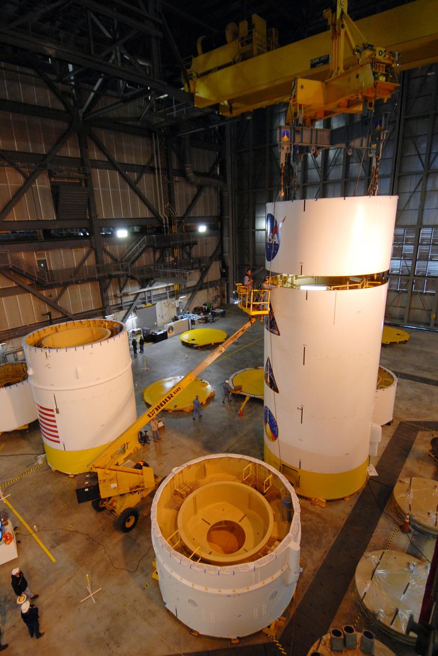
CAPE CANAVERAL, Fla. -- In high bay 4 of the Vehicle Assembly Building at NASA's Kennedy Space Center in Florida, a crane lowers segment 5 of the Ares I-X upper stage simulator segments onto segment 4, at top of the tall stack below. The upper stage simulator comprises 11 segments, each approximately 18 feet in diameter, that will be used in the test flight known as Ares I-X in 2009. The simulator segments will simulate the mass and the outer mold line. The upper stage accounts for nearly one-quarter of the total height of the Ares I. It will take the Ares I on the second phase of its journey from Earth, providing the guidance, navigation and control needed for the second phase of the Ares I ascent flight. Photo credit: NASA/Troy Cryder
NASA engineers install test hardware for the agency's new heavy lift rocket, the Space Launch System, into a newly constructed 50-foot structural test stand at NASA's Marshall Space Flight Center. In the stand, hydraulic cylinders will be electronically controlled to push, pull, twist and bend the test article with millions of pounds of force. Engineers will record and analyze over 3,000 channels of data for each test case to verify the capabilities of the engine section and validate that the design and analysis models accurately predict the amount of loads the core stage can withstand during launch and ascent. The engine section, recently delivered via NASA's barge Pegasus from NASA's Michoud Assembly Facility, is the first of four core stage structural test articles scheduled to be delivered to Marshall for testing. The engine section, located at the bottom of SLS's massive core stage, will house the rocket's four RS-25 engines and be an attachment point for the two solid rocket boosters.

NASA engineers install test hardware for the agency's new heavy lift rocket, the Space Launch System, into a newly constructed 50-foot structural test stand at NASA's Marshall Space Flight Center. In the stand, hydraulic cylinders will be electronically controlled to push, pull, twist and bend the test article with millions of pounds of force. Engineers will record and analyze over 3,000 channels of data for each test case to verify the capabilities of the engine section and validate that the design and analysis models accurately predict the amount of loads the core stage can withstand during launch and ascent. The engine section, recently delivered via NASA's barge Pegasus from NASA's Michoud Assembly Facility, is the first of four core stage structural test articles scheduled to be delivered to Marshall for testing. The engine section, located at the bottom of SLS's massive core stage, will house the rocket's four RS-25 engines and be an attachment point for the two solid rocket boosters.
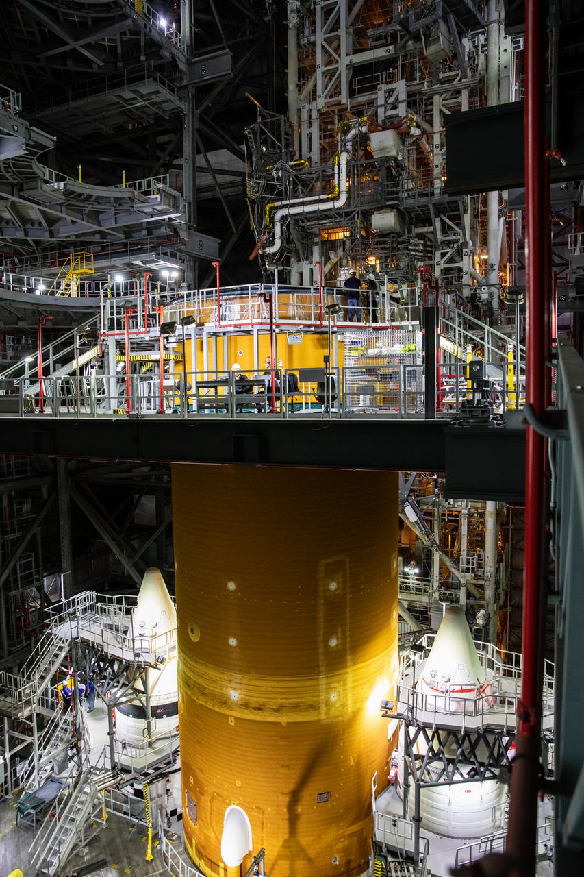
The Space Launch System (SLS) core stage is seen atop the mobile launcher inside High Bay 3 of the Vehicle Assembly Building at NASA’s Kennedy Space Center in Florida on June 15, 2021. Teams with NASA’s Exploration Ground Systems and contractor Jacobs lifted and lowered the core stage – the largest part of the rocket – onto the mobile launcher, placing it in between the twin solid rocket boosters. The 188,000-pound core stage, with its four RS-25 engines, will provide more than 2 million pounds of thrust during launch and ascent, and coupled with the boosters, will provide more than 8.8 million pounds of thrust to send the Artemis I mission to space. Under the Artemis program, NASA will land the first woman and first person of color on the Moon, as well as establish a sustainable presence on the lunar surface in preparation for human missions to Mars.
NASA engineers install test hardware for the agency's new heavy lift rocket, the Space Launch System, into a newly constructed 50-foot structural test stand at NASA's Marshall Space Flight Center. In the stand, hydraulic cylinders will be electronically controlled to push, pull, twist and bend the test article with millions of pounds of force. Engineers will record and analyze over 3,000 channels of data for each test case to verify the capabilities of the engine section and validate that the design and analysis models accurately predict the amount of loads the core stage can withstand during launch and ascent. The engine section, recently delivered via NASA's barge Pegasus from NASA's Michoud Assembly Facility, is the first of four core stage structural test articles scheduled to be delivered to Marshall for testing. The engine section, located at the bottom of SLS's massive core stage, will house the rocket's four RS-25 engines and be an attachment point for the two solid rocket boosters.
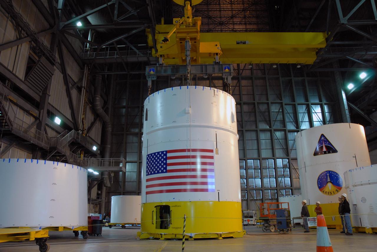
CAPE CANAVERAL, Fla. -- In high bay 4 of the Vehicle Assembly Building at NASA's Kennedy Space Center in Florida, the Ares I-X upper stage simulator segment 7 is stacked onto segment 6. The upper stage simulator comprises 11 segments, each approximately 18 feet in diameter, that will be used in the test flight identified as Ares I-X in 2009. The simulator segments will simulate the mass and the outer mold line. The upper stage accounts for nearly one-quarter of the total height of the Ares I. It will take the Ares I on the second phase of its journey from Earth, providing the guidance, navigation and control needed for the second phase of the Ares I ascent flight. Photo credit: NASA/Kim Shiflett
NASA engineers install test hardware for the agency's new heavy lift rocket, the Space Launch System, into a newly constructed 50-foot structural test stand at NASA's Marshall Space Flight Center. In the stand, hydraulic cylinders will be electronically controlled to push, pull, twist and bend the test article with millions of pounds of force. Engineers will record and analyze over 3,000 channels of data for each test case to verify the capabilities of the engine section and validate that the design and analysis models accurately predict the amount of loads the core stage can withstand during launch and ascent. The engine section, recently delivered via NASA's barge Pegasus from NASA's Michoud Assembly Facility, is the first of four core stage structural test articles scheduled to be delivered to Marshall for testing. The engine section, located at the bottom of SLS's massive core stage, will house the rocket's four RS-25 engines and be an attachment point for the two solid rocket boosters.
NASA engineers install test hardware for the agency's new heavy lift rocket, the Space Launch System, into a newly constructed 50-foot structural test stand at NASA's Marshall Space Flight Center. In the stand, hydraulic cylinders will be electronically controlled to push, pull, twist and bend the test article with millions of pounds of force. Engineers will record and analyze over 3,000 channels of data for each test case to verify the capabilities of the engine section and validate that the design and analysis models accurately predict the amount of loads the core stage can withstand during launch and ascent. The engine section, recently delivered via NASA's barge Pegasus from NASA's Michoud Assembly Facility, is the first of four core stage structural test articles scheduled to be delivered to Marshall for testing. The engine section, located at the bottom of SLS's massive core stage, will house the rocket's four RS-25 engines and be an attachment point for the two solid rocket boosters.
CAPE CANAVERAL, Fla. -- In high bay 4 of the Vehicle Assembly Building at NASA's Kennedy Space Center in Florida, work is under way to stack the Ares I-X upper stage simulator segment 5 to segment 4. The upper stage simulator comprises 11 segments, each approximately 18 feet in diameter, that will be used in the test flight known as Ares I-X in 2009. The simulator segments will simulate the mass and the outer mold line. The upper stage accounts for nearly one-quarter of the total height of the Ares I. It will take the Ares I on the second phase of its journey from Earth, providing the guidance, navigation and control needed for the second phase of the Ares I ascent flight. Photo credit: NASA/Jim Grossmann
NASA engineers install test hardware for the agency's new heavy lift rocket, the Space Launch System, into a newly constructed 50-foot structural test stand at NASA's Marshall Space Flight Center. In the stand, hydraulic cylinders will be electronically controlled to push, pull, twist and bend the test article with millions of pounds of force. Engineers will record and analyze over 3,000 channels of data for each test case to verify the capabilities of the engine section and validate that the design and analysis models accurately predict the amount of loads the core stage can withstand during launch and ascent. The engine section, recently delivered via NASA's barge Pegasus from NASA's Michoud Assembly Facility, is the first of four core stage structural test articles scheduled to be delivered to Marshall for testing. The engine section, located at the bottom of SLS's massive core stage, will house the rocket's four RS-25 engines and be an attachment point for the two solid rocket boosters.
NASA engineers install test hardware for the agency's new heavy lift rocket, the Space Launch System, into a newly constructed 50-foot structural test stand at NASA's Marshall Space Flight Center. In the stand, hydraulic cylinders will be electronically controlled to push, pull, twist and bend the test article with millions of pounds of force. Engineers will record and analyze over 3,000 channels of data for each test case to verify the capabilities of the engine section and validate that the design and analysis models accurately predict the amount of loads the core stage can withstand during launch and ascent. The engine section, recently delivered via NASA's barge Pegasus from NASA's Michoud Assembly Facility, is the first of four core stage structural test articles scheduled to be delivered to Marshall for testing. The engine section, located at the bottom of SLS's massive core stage, will house the rocket's four RS-25 engines and be an attachment point for the two solid rocket boosters.
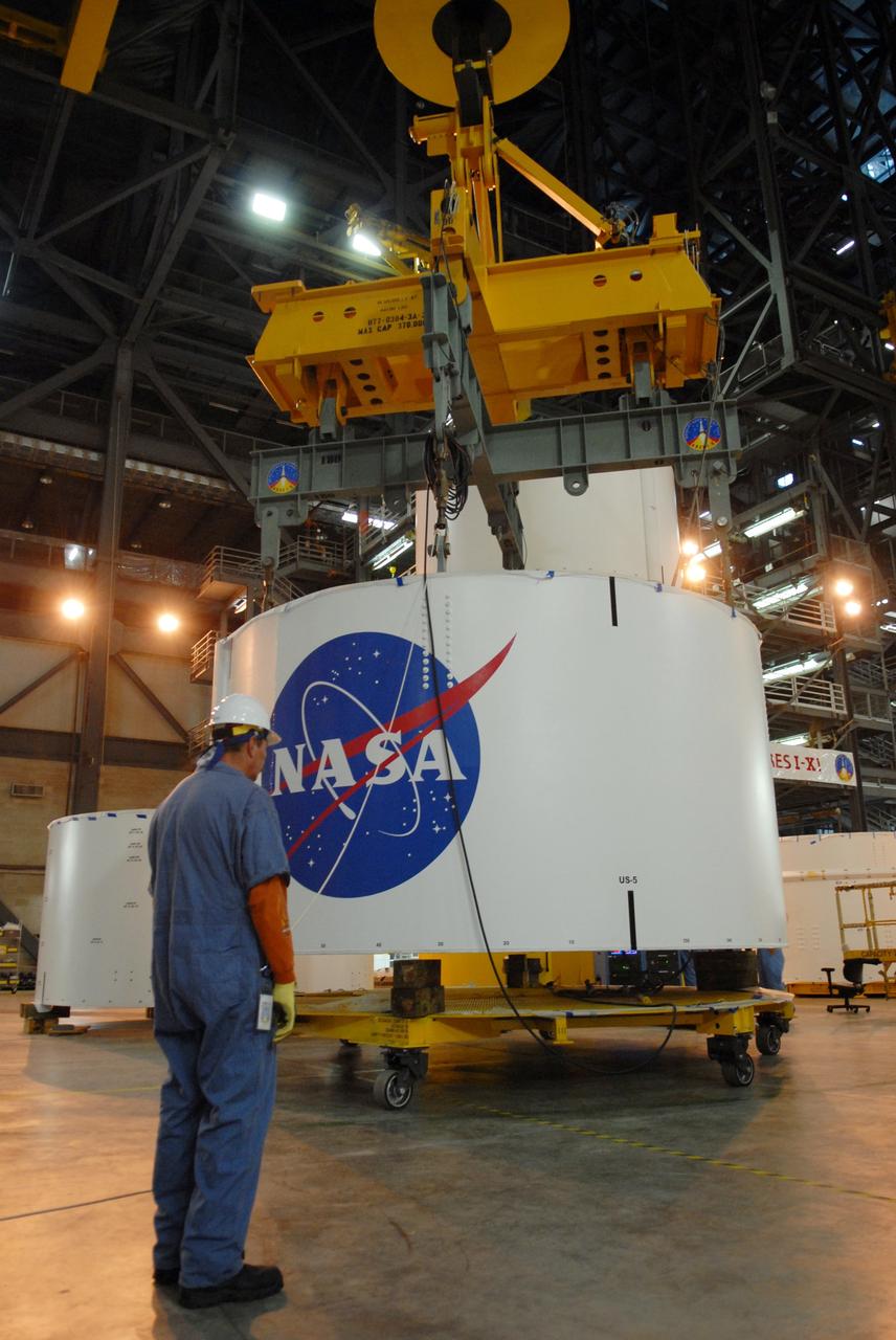
CAPE CANAVERAL, Fla. -- In high bay 4 of the Vehicle Assembly Building at NASA's Kennedy Space Center in Florida, a crane lifts segment 5 of the Ares I-X upper stage simulator segments. It will be placed on segment 4, at top of the tall stack behind it.The upper stage simulator comprises 11 segments, each approximately 18 feet in diameter, that will be used in the test flight known as Ares I-X in 2009. The simulator segments will simulate the mass and the outer mold line. The upper stage accounts for nearly one-quarter of the total height of the Ares I. It will take the Ares I on the second phase of its journey from Earth, providing the guidance, navigation and control needed for the second phase of the Ares I ascent flight. Photo credit: NASA/Troy Cryder
NASA engineers install test hardware for the agency's new heavy lift rocket, the Space Launch System, into a newly constructed 50-foot structural test stand at NASA's Marshall Space Flight Center. In the stand, hydraulic cylinders will be electronically controlled to push, pull, twist and bend the test article with millions of pounds of force. Engineers will record and analyze over 3,000 channels of data for each test case to verify the capabilities of the engine section and validate that the design and analysis models accurately predict the amount of loads the core stage can withstand during launch and ascent. The engine section, recently delivered via NASA's barge Pegasus from NASA's Michoud Assembly Facility, is the first of four core stage structural test articles scheduled to be delivered to Marshall for testing. The engine section, located at the bottom of SLS's massive core stage, will house the rocket's four RS-25 engines and be an attachment point for the two solid rocket boosters.
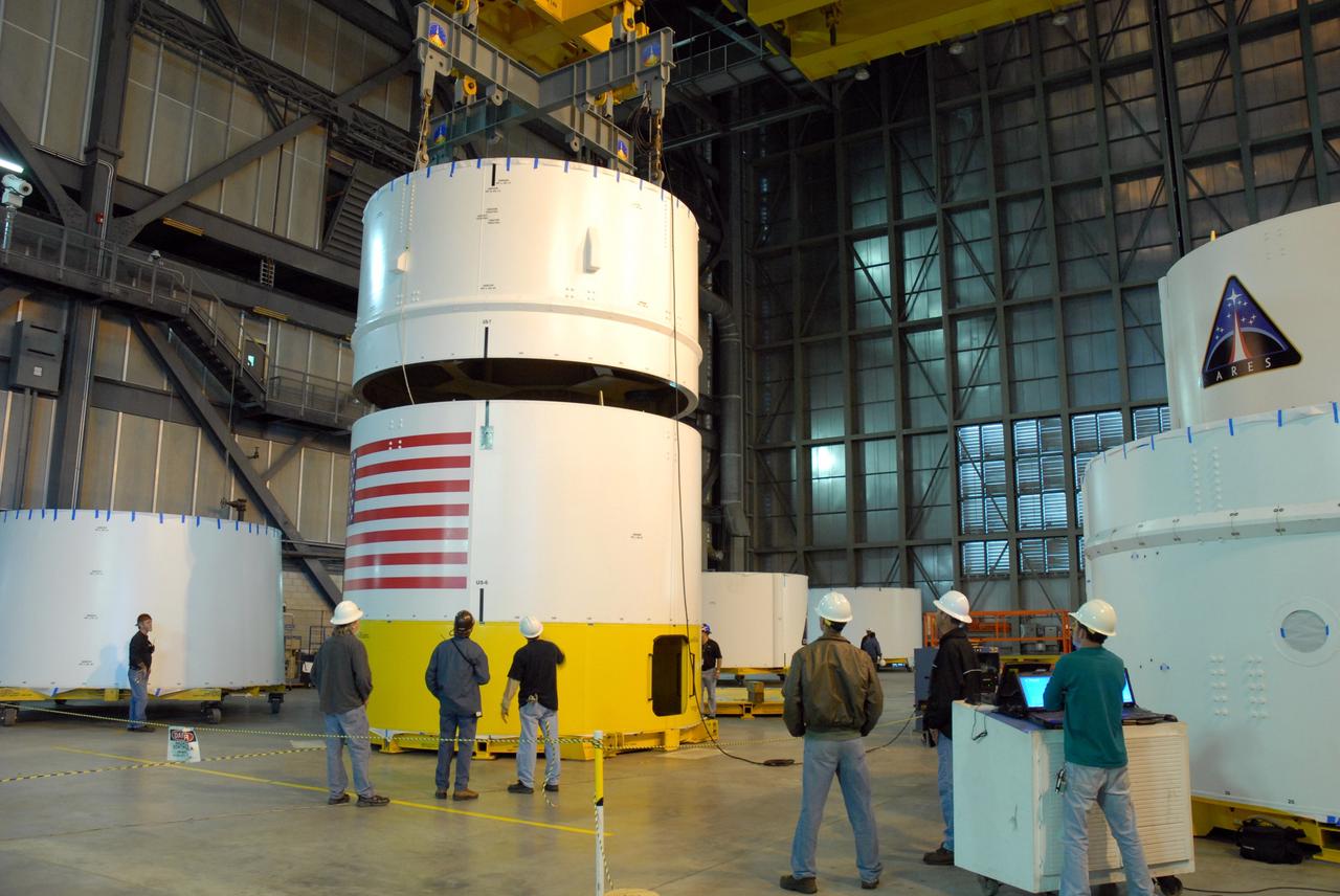
CAPE CANAVERAL, Fla. -- In high bay 4 of the Vehicle Assembly Building at NASA's Kennedy Space Center in Florida, a crane lowers the Ares I-X upper stage simulator segment 7 toward segment 6. The upper stage simulator comprises 11 segments, each approximately 18 feet in diameter, that will be used in the test flight identified as Ares I-X in 2009. The simulator segments will simulate the mass and the outer mold line. The upper stage accounts for nearly one-quarter of the total height of the Ares I. It will take the Ares I on the second phase of its journey from Earth, providing the guidance, navigation and control needed for the second phase of the Ares I ascent flight. Photo credit: NASA/Kim Shiflett
NASA engineers install test hardware for the agency's new heavy lift rocket, the Space Launch System, into a newly constructed 50-foot structural test stand at NASA's Marshall Space Flight Center. In the stand, hydraulic cylinders will be electronically controlled to push, pull, twist and bend the test article with millions of pounds of force. Engineers will record and analyze over 3,000 channels of data for each test case to verify the capabilities of the engine section and validate that the design and analysis models accurately predict the amount of loads the core stage can withstand during launch and ascent. The engine section, recently delivered via NASA's barge Pegasus from NASA's Michoud Assembly Facility, is the first of four core stage structural test articles scheduled to be delivered to Marshall for testing. The engine section, located at the bottom of SLS's massive core stage, will house the rocket's four RS-25 engines and be an attachment point for the two solid rocket boosters.
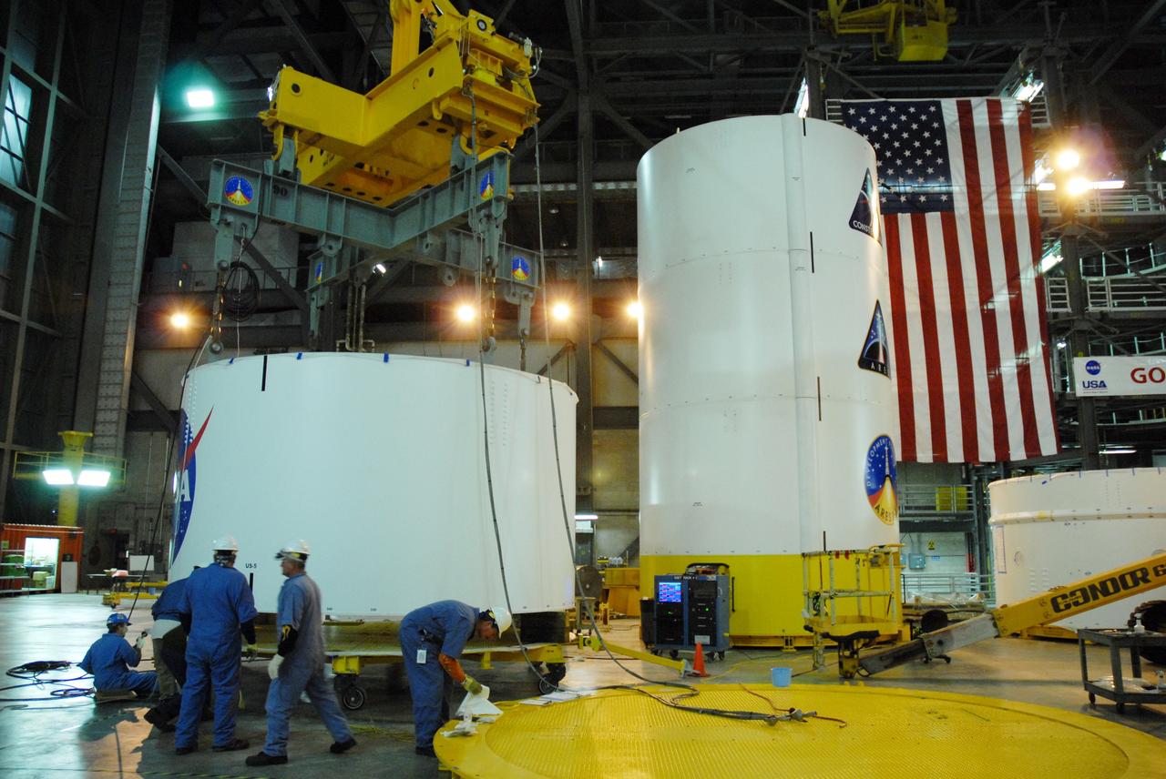
CAPE CANAVERAL, Fla. -- In high bay 4 of the Vehicle Assembly Building at NASA's Kennedy Space Center in Florida, a crane is attached to segment 5 of the Ares I-X upper stage simulator segments to lift it. Segment 5 will be stacked on to segment 4, at the top of the tall stack at right. The upper stage simulator comprises 11 segments, each approximately 18 feet in diameter, that will be used in the test flight known as Ares I-X in 2009. The simulator segments will simulate the mass and the outer mold line. The upper stage accounts for nearly one-quarter of the total height of the Ares I. It will take the Ares I on the second phase of its journey from Earth, providing the guidance, navigation and control needed for the second phase of the Ares I ascent flight. Photo credit: NASA/Jim Grossmann
NASA engineers install test hardware for the agency's new heavy lift rocket, the Space Launch System, into a newly constructed 50-foot structural test stand at NASA's Marshall Space Flight Center. In the stand, hydraulic cylinders will be electronically controlled to push, pull, twist and bend the test article with millions of pounds of force. Engineers will record and analyze over 3,000 channels of data for each test case to verify the capabilities of the engine section and validate that the design and analysis models accurately predict the amount of loads the core stage can withstand during launch and ascent. The engine section, recently delivered via NASA's barge Pegasus from NASA's Michoud Assembly Facility, is the first of four core stage structural test articles scheduled to be delivered to Marshall for testing. The engine section, located at the bottom of SLS's massive core stage, will house the rocket's four RS-25 engines and be an attachment point for the two solid rocket boosters.
CAPE CANAVERAL, Fla. -- In high bay 4 of the Vehicle Assembly Building at NASA's Kennedy Space Center in Florida, a crane lowers segment 5 of the Ares I-X upper stage simulator segments toward segment 4, at top of the tall stack below. The upper stage simulator comprises 11 segments, each approximately 18 feet in diameter, that will be used in the test flight known as Ares I-X in 2009. The simulator segments will simulate the mass and the outer mold line. The upper stage accounts for nearly one-quarter of the total height of the Ares I. It will take the Ares I on the second phase of its journey from Earth, providing the guidance, navigation and control needed for the second phase of the Ares I ascent flight. Photo credit: NASA/Troy Cryder

CAPE CANAVERAL, Fla. -- In high bay 4 of the Vehicle Assembly Building at NASA's Kennedy Space Center in Florida, a crane is ready to lift the Ares I-X upper stage simulator segment 7. The segment will be stacked onto segment 6. The upper stage simulator comprises 11 segments, each approximately 18 feet in diameter, that will be used in the test flight identified as Ares I-X in 2009. The simulator segments will simulate the mass and the outer mold line. The upper stage accounts for nearly one-quarter of the total height of the Ares I. It will take the Ares I on the second phase of its journey from Earth, providing the guidance, navigation and control needed for the second phase of the Ares I ascent flight. Photo credit: NASA/Kim Shiflett

The Space Launch System (SLS) core stage is seen atop the mobile launcher inside High Bay 3 of the Vehicle Assembly Building at NASA’s Kennedy Space Center in Florida on June 12, 2021. Teams with NASA’s Exploration Ground Systems and contractor Jacobs lifted and lowered the core stage – the largest part of the rocket – onto the mobile launcher, placing it in between the twin solid rocket boosters. The 188,000-pound core stage, with its four RS-25 engines, will provide more than 2 million pounds of thrust during launch and ascent, and coupled with the boosters, will provide more than 8.8 million pounds of thrust to send the Artemis I mission to space. Under the Artemis program, NASA will land the first woman and first person of color on the Moon, as well as establish a sustainable presence on the lunar surface in preparation for human missions to Mars.
NASA engineers install test hardware for the agency's new heavy lift rocket, the Space Launch System, into a newly constructed 50-foot structural test stand at NASA's Marshall Space Flight Center. In the stand, hydraulic cylinders will be electronically controlled to push, pull, twist and bend the test article with millions of pounds of force. Engineers will record and analyze over 3,000 channels of data for each test case to verify the capabilities of the engine section and validate that the design and analysis models accurately predict the amount of loads the core stage can withstand during launch and ascent. The engine section, recently delivered via NASA's barge Pegasus from NASA's Michoud Assembly Facility, is the first of four core stage structural test articles scheduled to be delivered to Marshall for testing. The engine section, located at the bottom of SLS's massive core stage, will house the rocket's four RS-25 engines and be an attachment point for the two solid rocket boosters.
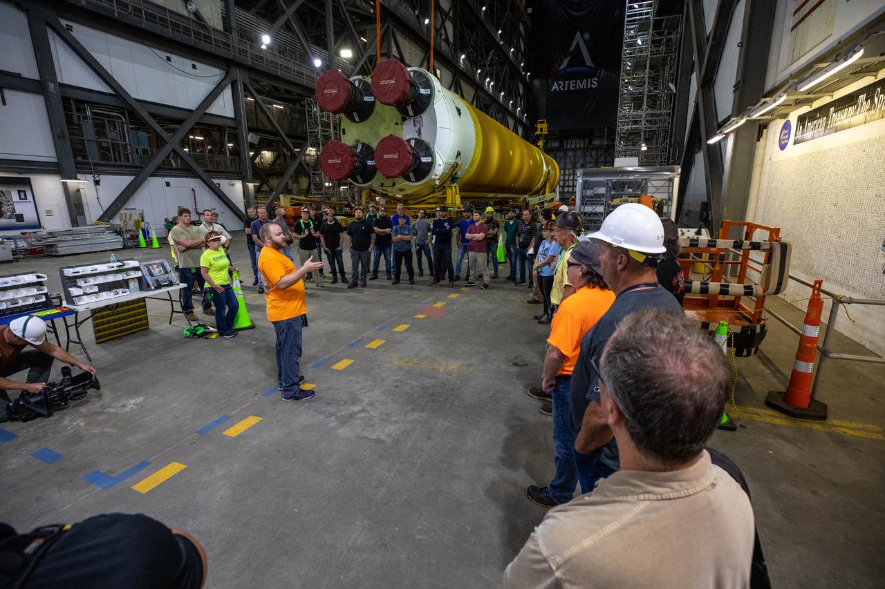
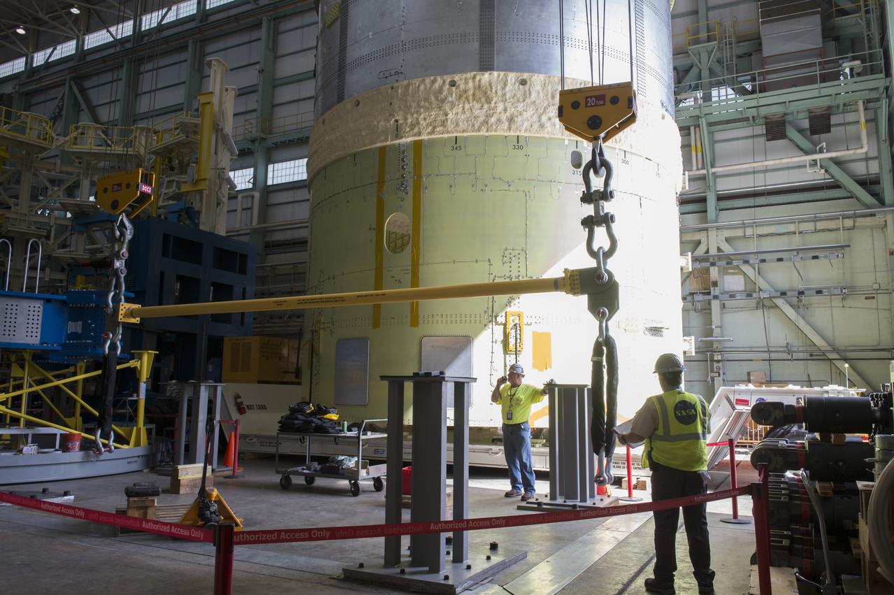
The Space Launch System (SLS) core stage is seen in the transfer aisle of the Vehicle Assembly Building (VAB) at NASA’s Kennedy Space Center in Florida on June 9, 2021. Teams with the agency’s Exploration Ground Systems and contractor Jacobs are preparing to lift the 188,000-pound core stage, which is the largest part of the rocket, and place it on the mobile launcher in between the two solid rocket boosters in High Bay 3 of the VAB. The core stage alone, with its four RS-25 engines, will provide more than 2 million pounds of thrust during launch and ascent, and coupled with the boosters, will provide more than 8.8 million pounds of thrust to send the Artemis I mission to space. The first in an increasingly complex series of missions, Artemis I will test SLS and the Orion spacecraft as an integrated system ahead of crewed flights to the Moon.

NASA engineers install test hardware for the agency's new heavy lift rocket, the Space Launch System, into a newly constructed 50-foot structural test stand at NASA's Marshall Space Flight Center. In the stand, hydraulic cylinders will be electronically controlled to push, pull, twist and bend the test article with millions of pounds of force. Engineers will record and analyze over 3,000 channels of data for each test case to verify the capabilities of the engine section and validate that the design and analysis models accurately predict the amount of loads the core stage can withstand during launch and ascent. The engine section, recently delivered via NASA's barge Pegasus from NASA's Michoud Assembly Facility, is the first of four core stage structural test articles scheduled to be delivered to Marshall for testing. The engine section, located at the bottom of SLS's massive core stage, will house the rocket's four RS-25 engines and be an attachment point for the two solid rocket boosters.
NASA engineers install test hardware for the agency's new heavy lift rocket, the Space Launch System, into a newly constructed 50-foot structural test stand at NASA's Marshall Space Flight Center. In the stand, hydraulic cylinders will be electronically controlled to push, pull, twist and bend the test article with millions of pounds of force. Engineers will record and analyze over 3,000 channels of data for each test case to verify the capabilities of the engine section and validate that the design and analysis models accurately predict the amount of loads the core stage can withstand during launch and ascent. The engine section, recently delivered via NASA's barge Pegasus from NASA's Michoud Assembly Facility, is the first of four core stage structural test articles scheduled to be delivered to Marshall for testing. The engine section, located at the bottom of SLS's massive core stage, will house the rocket's four RS-25 engines and be an attachment point for the two solid rocket boosters.
CAPE CANAVERAL, Fla. -- In high bay 4 of the Vehicle Assembly Building at NASA's Kennedy Space Center in Florida, a crane lifts the Ares I-X upper stage simulator segment 7. The segment will be stacked onto segment 6. The upper stage simulator comprises 11 segments, each approximately 18 feet in diameter, that will be used in the test flight identified as Ares I-X in 2009. The simulator segments will simulate the mass and the outer mold line. The upper stage accounts for nearly one-quarter of the total height of the Ares I. It will take the Ares I on the second phase of its journey from Earth, providing the guidance, navigation and control needed for the second phase of the Ares I ascent flight. Photo credit: NASA/Kim Shiflett
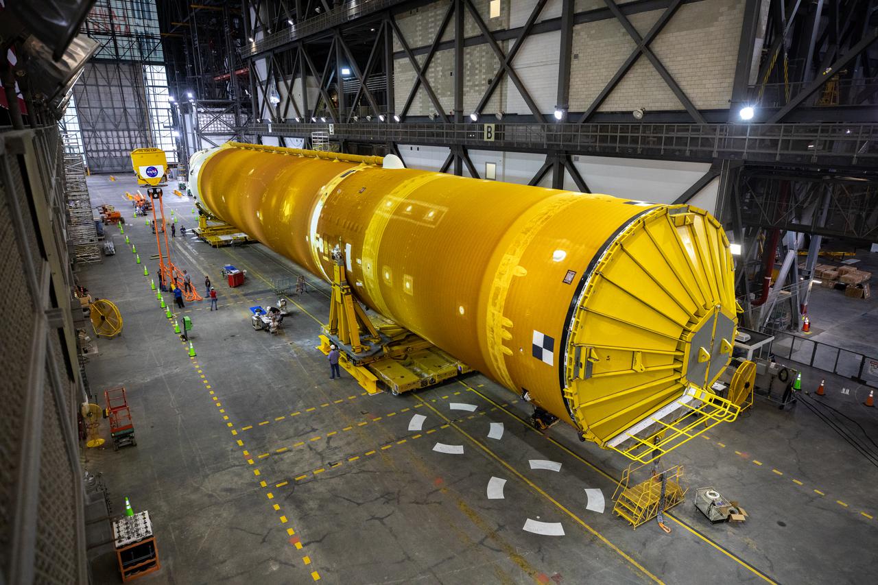
The Space Launch System (SLS) core stage is seen in the transfer aisle of the Vehicle Assembly Building (VAB) at NASA’s Kennedy Space Center in Florida on June 9, 2021. Teams with the agency’s Exploration Ground Systems and contractor Jacobs are preparing to lift the 188,000-pound core stage, which is the largest part of the rocket, and place it on the mobile launcher in between the two solid rocket boosters in High Bay 3 of the VAB. The core stage alone, with its four RS-25 engines, will provide more than 2 million pounds of thrust during launch and ascent, and coupled with the boosters, will provide more than 8.8 million pounds of thrust to send the Artemis I mission to space. The first in an increasingly complex series of missions, Artemis I will test SLS and the Orion spacecraft as an integrated system ahead of crewed flights to the Moon.

NASA engineers install test hardware for the agency's new heavy lift rocket, the Space Launch System, into a newly constructed 50-foot structural test stand at NASA's Marshall Space Flight Center. In the stand, hydraulic cylinders will be electronically controlled to push, pull, twist and bend the test article with millions of pounds of force. Engineers will record and analyze over 3,000 channels of data for each test case to verify the capabilities of the engine section and validate that the design and analysis models accurately predict the amount of loads the core stage can withstand during launch and ascent. The engine section, recently delivered via NASA's barge Pegasus from NASA's Michoud Assembly Facility, is the first of four core stage structural test articles scheduled to be delivered to Marshall for testing. The engine section, located at the bottom of SLS's massive core stage, will house the rocket's four RS-25 engines and be an attachment point for the two solid rocket boosters.
NASA engineers install test hardware for the agency's new heavy lift rocket, the Space Launch System, into a newly constructed 50-foot structural test stand at NASA's Marshall Space Flight Center. In the stand, hydraulic cylinders will be electronically controlled to push, pull, twist and bend the test article with millions of pounds of force. Engineers will record and analyze over 3,000 channels of data for each test case to verify the capabilities of the engine section and validate that the design and analysis models accurately predict the amount of loads the core stage can withstand during launch and ascent. The engine section, recently delivered via NASA's barge Pegasus from NASA's Michoud Assembly Facility, is the first of four core stage structural test articles scheduled to be delivered to Marshall for testing. The engine section, located at the bottom of SLS's massive core stage, will house the rocket's four RS-25 engines and be an attachment point for the two solid rocket boosters.
CAPE CANAVERAL, Fla. -- In high bay 4 of the Vehicle Assembly Building at NASA's Kennedy Space Center in Florida, a crane lifts segment 5 of the Ares I-X upper stage simulator segments. It will be placed on segment 4, at top of the tall stack behind it. The upper stage simulator comprises 11 segments, each approximately 18 feet in diameter, that will be used in the test flight known as Ares I-X in 2009. The simulator segments will simulate the mass and the outer mold line. The upper stage accounts for nearly one-quarter of the total height of the Ares I. It will take the Ares I on the second phase of its journey from Earth, providing the guidance, navigation and control needed for the second phase of the Ares I ascent flight. Photo credit: NASA/Troy Cryder
NASA engineers install test hardware for the agency's new heavy lift rocket, the Space Launch System, into a newly constructed 50-foot structural test stand at NASA's Marshall Space Flight Center. In the stand, hydraulic cylinders will be electronically controlled to push, pull, twist and bend the test article with millions of pounds of force. Engineers will record and analyze over 3,000 channels of data for each test case to verify the capabilities of the engine section and validate that the design and analysis models accurately predict the amount of loads the core stage can withstand during launch and ascent. The engine section, recently delivered via NASA's barge Pegasus from NASA's Michoud Assembly Facility, is the first of four core stage structural test articles scheduled to be delivered to Marshall for testing. The engine section, located at the bottom of SLS's massive core stage, will house the rocket's four RS-25 engines and be an attachment point for the two solid rocket boosters.
NASA engineers install test hardware for the agency's new heavy lift rocket, the Space Launch System, into a newly constructed 50-foot structural test stand at NASA's Marshall Space Flight Center. In the stand, hydraulic cylinders will be electronically controlled to push, pull, twist and bend the test article with millions of pounds of force. Engineers will record and analyze over 3,000 channels of data for each test case to verify the capabilities of the engine section and validate that the design and analysis models accurately predict the amount of loads the core stage can withstand during launch and ascent. The engine section, recently delivered via NASA's barge Pegasus from NASA's Michoud Assembly Facility, is the first of four core stage structural test articles scheduled to be delivered to Marshall for testing. The engine section, located at the bottom of SLS's massive core stage, will house the rocket's four RS-25 engines and be an attachment point for the two solid rocket boosters.
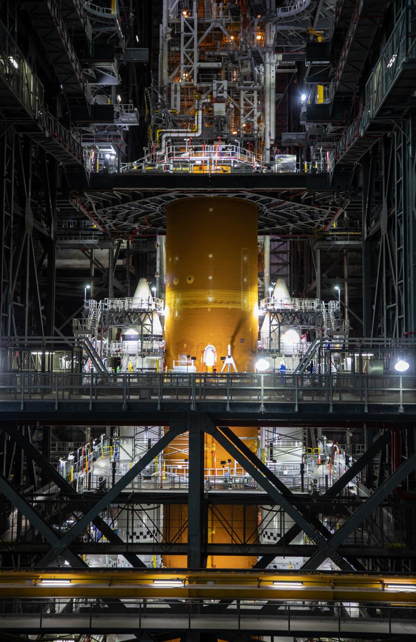
The Space Launch System (SLS) core stage is seen atop the mobile launcher inside High Bay 3 of the Vehicle Assembly Building at NASA’s Kennedy Space Center in Florida on June 15, 2021. Teams with NASA’s Exploration Ground Systems and contractor Jacobs lifted and lowered the core stage – the largest part of the rocket – onto the mobile launcher, placing it in between the twin solid rocket boosters. The 188,000-pound core stage, with its four RS-25 engines, will provide more than 2 million pounds of thrust during launch and ascent, and coupled with the boosters, will provide more than 8.8 million pounds of thrust to send the Artemis I mission to space. Under the Artemis program, NASA will land the first woman and first person of color on the Moon, as well as establish a sustainable presence on the lunar surface in preparation for human missions to Mars.
NASA engineers install test hardware for the agency's new heavy lift rocket, the Space Launch System, into a newly constructed 50-foot structural test stand at NASA's Marshall Space Flight Center. In the stand, hydraulic cylinders will be electronically controlled to push, pull, twist and bend the test article with millions of pounds of force. Engineers will record and analyze over 3,000 channels of data for each test case to verify the capabilities of the engine section and validate that the design and analysis models accurately predict the amount of loads the core stage can withstand during launch and ascent. The engine section, recently delivered via NASA's barge Pegasus from NASA's Michoud Assembly Facility, is the first of four core stage structural test articles scheduled to be delivered to Marshall for testing. The engine section, located at the bottom of SLS's massive core stage, will house the rocket's four RS-25 engines and be an attachment point for the two solid rocket boosters.
NASA engineers install test hardware for the agency's new heavy lift rocket, the Space Launch System, into a newly constructed 50-foot structural test stand at NASA's Marshall Space Flight Center. In the stand, hydraulic cylinders will be electronically controlled to push, pull, twist and bend the test article with millions of pounds of force. Engineers will record and analyze over 3,000 channels of data for each test case to verify the capabilities of the engine section and validate that the design and analysis models accurately predict the amount of loads the core stage can withstand during launch and ascent. The engine section, recently delivered via NASA's barge Pegasus from NASA's Michoud Assembly Facility, is the first of four core stage structural test articles scheduled to be delivered to Marshall for testing. The engine section, located at the bottom of SLS's massive core stage, will house the rocket's four RS-25 engines and be an attachment point for the two solid rocket boosters.
NASA engineers install test hardware for the agency's new heavy lift rocket, the Space Launch System, into a newly constructed 50-foot structural test stand at NASA's Marshall Space Flight Center. In the stand, hydraulic cylinders will be electronically controlled to push, pull, twist and bend the test article with millions of pounds of force. Engineers will record and analyze over 3,000 channels of data for each test case to verify the capabilities of the engine section and validate that the design and analysis models accurately predict the amount of loads the core stage can withstand during launch and ascent. The engine section, recently delivered via NASA's barge Pegasus from NASA's Michoud Assembly Facility, is the first of four core stage structural test articles scheduled to be delivered to Marshall for testing. The engine section, located at the bottom of SLS's massive core stage, will house the rocket's four RS-25 engines and be an attachment point for the two solid rocket boosters.
NASA engineers install test hardware for the agency's new heavy lift rocket, the Space Launch System, into a newly constructed 50-foot structural test stand at NASA's Marshall Space Flight Center. In the stand, hydraulic cylinders will be electronically controlled to push, pull, twist and bend the test article with millions of pounds of force. Engineers will record and analyze over 3,000 channels of data for each test case to verify the capabilities of the engine section and validate that the design and analysis models accurately predict the amount of loads the core stage can withstand during launch and ascent. The engine section, recently delivered via NASA's barge Pegasus from NASA's Michoud Assembly Facility, is the first of four core stage structural test articles scheduled to be delivered to Marshall for testing. The engine section, located at the bottom of SLS's massive core stage, will house the rocket's four RS-25 engines and be an attachment point for the two solid rocket boosters.
NASA engineers install test hardware for the agency's new heavy lift rocket, the Space Launch System, into a newly constructed 50-foot structural test stand at NASA's Marshall Space Flight Center. In the stand, hydraulic cylinders will be electronically controlled to push, pull, twist and bend the test article with millions of pounds of force. Engineers will record and analyze over 3,000 channels of data for each test case to verify the capabilities of the engine section and validate that the design and analysis models accurately predict the amount of loads the core stage can withstand during launch and ascent. The engine section, recently delivered via NASA's barge Pegasus from NASA's Michoud Assembly Facility, is the first of four core stage structural test articles scheduled to be delivered to Marshall for testing. The engine section, located at the bottom of SLS's massive core stage, will house the rocket's four RS-25 engines and be an attachment point for the two solid rocket boosters.
NASA engineers install test hardware for the agency's new heavy lift rocket, the Space Launch System, into a newly constructed 50-foot structural test stand at NASA's Marshall Space Flight Center. In the stand, hydraulic cylinders will be electronically controlled to push, pull, twist and bend the test article with millions of pounds of force. Engineers will record and analyze over 3,000 channels of data for each test case to verify the capabilities of the engine section and validate that the design and analysis models accurately predict the amount of loads the core stage can withstand during launch and ascent. The engine section, recently delivered via NASA's barge Pegasus from NASA's Michoud Assembly Facility, is the first of four core stage structural test articles scheduled to be delivered to Marshall for testing. The engine section, located at the bottom of SLS's massive core stage, will house the rocket's four RS-25 engines and be an attachment point for the two solid rocket boosters.
NASA engineers install test hardware for the agency's new heavy lift rocket, the Space Launch System, into a newly constructed 50-foot structural test stand at NASA's Marshall Space Flight Center. In the stand, hydraulic cylinders will be electronically controlled to push, pull, twist and bend the test article with millions of pounds of force. Engineers will record and analyze over 3,000 channels of data for each test case to verify the capabilities of the engine section and validate that the design and analysis models accurately predict the amount of loads the core stage can withstand during launch and ascent. The engine section, recently delivered via NASA's barge Pegasus from NASA's Michoud Assembly Facility, is the first of four core stage structural test articles scheduled to be delivered to Marshall for testing. The engine section, located at the bottom of SLS's massive core stage, will house the rocket's four RS-25 engines and be an attachment point for the two solid rocket boosters.
NASA engineers install test hardware for the agency's new heavy lift rocket, the Space Launch System, into a newly constructed 50-foot structural test stand at NASA's Marshall Space Flight Center. In the stand, hydraulic cylinders will be electronically controlled to push, pull, twist and bend the test article with millions of pounds of force. Engineers will record and analyze over 3,000 channels of data for each test case to verify the capabilities of the engine section and validate that the design and analysis models accurately predict the amount of loads the core stage can withstand during launch and ascent. The engine section, recently delivered via NASA's barge Pegasus from NASA's Michoud Assembly Facility, is the first of four core stage structural test articles scheduled to be delivered to Marshall for testing. The engine section, located at the bottom of SLS's massive core stage, will house the rocket's four RS-25 engines and be an attachment point for the two solid rocket boosters.
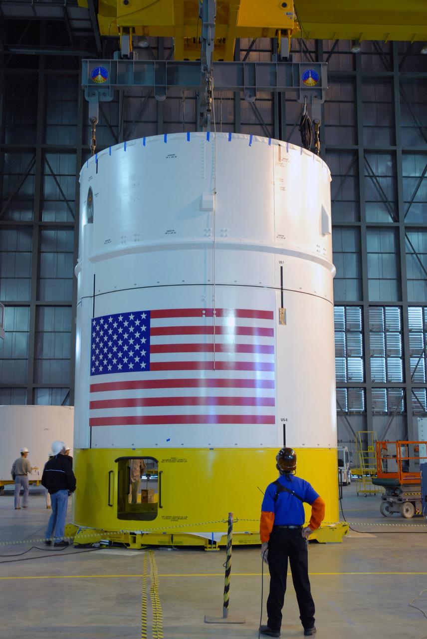
CAPE CANAVERAL, Fla. -- In high bay 4 of the Vehicle Assembly Building at NASA's Kennedy Space Center in Florida, a crane lowers the Ares I-X upper stage simulator segment 7 onto segment 6. The upper stage simulator comprises 11 segments, each approximately 18 feet in diameter, that will be used in the test flight identified as Ares I-X in 2009. The simulator segments will simulate the mass and the outer mold line. The upper stage accounts for nearly one-quarter of the total height of the Ares I. It will take the Ares I on the second phase of its journey from Earth, providing the guidance, navigation and control needed for the second phase of the Ares I ascent flight. Photo credit: NASA/Kim Shiflett
NASA engineers install test hardware for the agency's new heavy lift rocket, the Space Launch System, into a newly constructed 50-foot structural test stand at NASA's Marshall Space Flight Center. In the stand, hydraulic cylinders will be electronically controlled to push, pull, twist and bend the test article with millions of pounds of force. Engineers will record and analyze over 3,000 channels of data for each test case to verify the capabilities of the engine section and validate that the design and analysis models accurately predict the amount of loads the core stage can withstand during launch and ascent. The engine section, recently delivered via NASA's barge Pegasus from NASA's Michoud Assembly Facility, is the first of four core stage structural test articles scheduled to be delivered to Marshall for testing. The engine section, located at the bottom of SLS's massive core stage, will house the rocket's four RS-25 engines and be an attachment point for the two solid rocket boosters.
CAPE CANAVERAL, Fla. -- In high bay 4 of the Vehicle Assembly Building at NASA's Kennedy Space Center in Florida, a crane moves segment 5 of the Ares I-X upper stage simulator segments toward the tall stack behind it. Segment 5 will be placed on segment 4, at top of the tall stack. The upper stage simulator comprises 11 segments, each approximately 18 feet in diameter, that will be used in the test flight known as Ares I-X in 2009. The simulator segments will simulate the mass and the outer mold line. The upper stage accounts for nearly one-quarter of the total height of the Ares I. It will take the Ares I on the second phase of its journey from Earth, providing the guidance, navigation and control needed for the second phase of the Ares I ascent flight. Photo credit: NASA/Troy Cryder