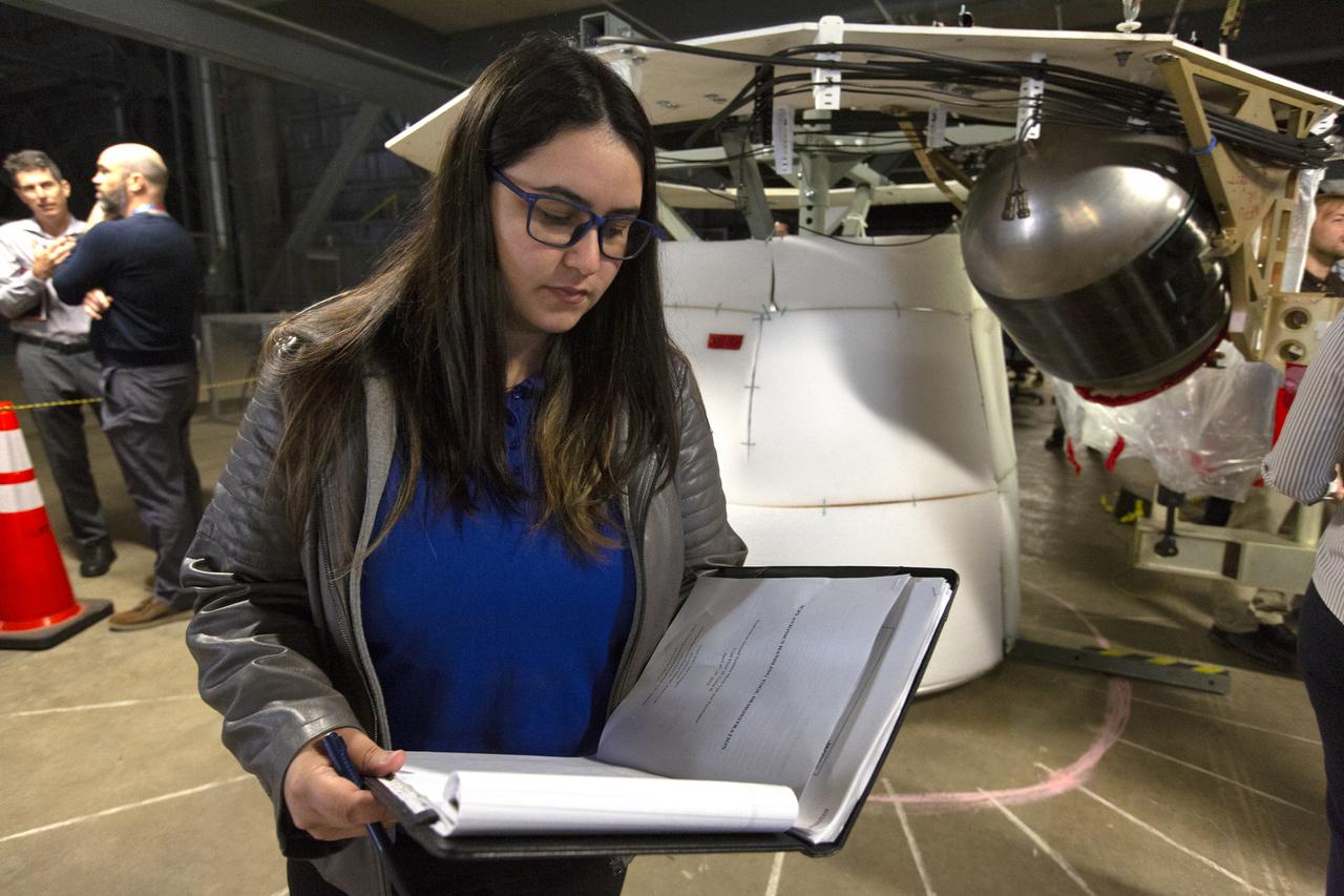
NASA Flight Systems Engineer Sherild Rivera Melendez takes notes during the Space Launch System avionics handling tool demonstration inside Kennedy Space Center’s Vehicle Assembly Building on April 4, 2019. The demonstration showed that avionics boxes could be successfully and safely mounted into the SLS rocket’s upper stage — called the Interim Cryogenic Propulsion Stage, or ICPS — with low risk of damaging a closely located hydrazine tank. Avionics boxes include the Inertial Navigation and Control Assembly and flight batteries. Rivera Melendez coordinated multiple human factors teams, focusing on life cycle reviews and impact risks during installation of the avionics.
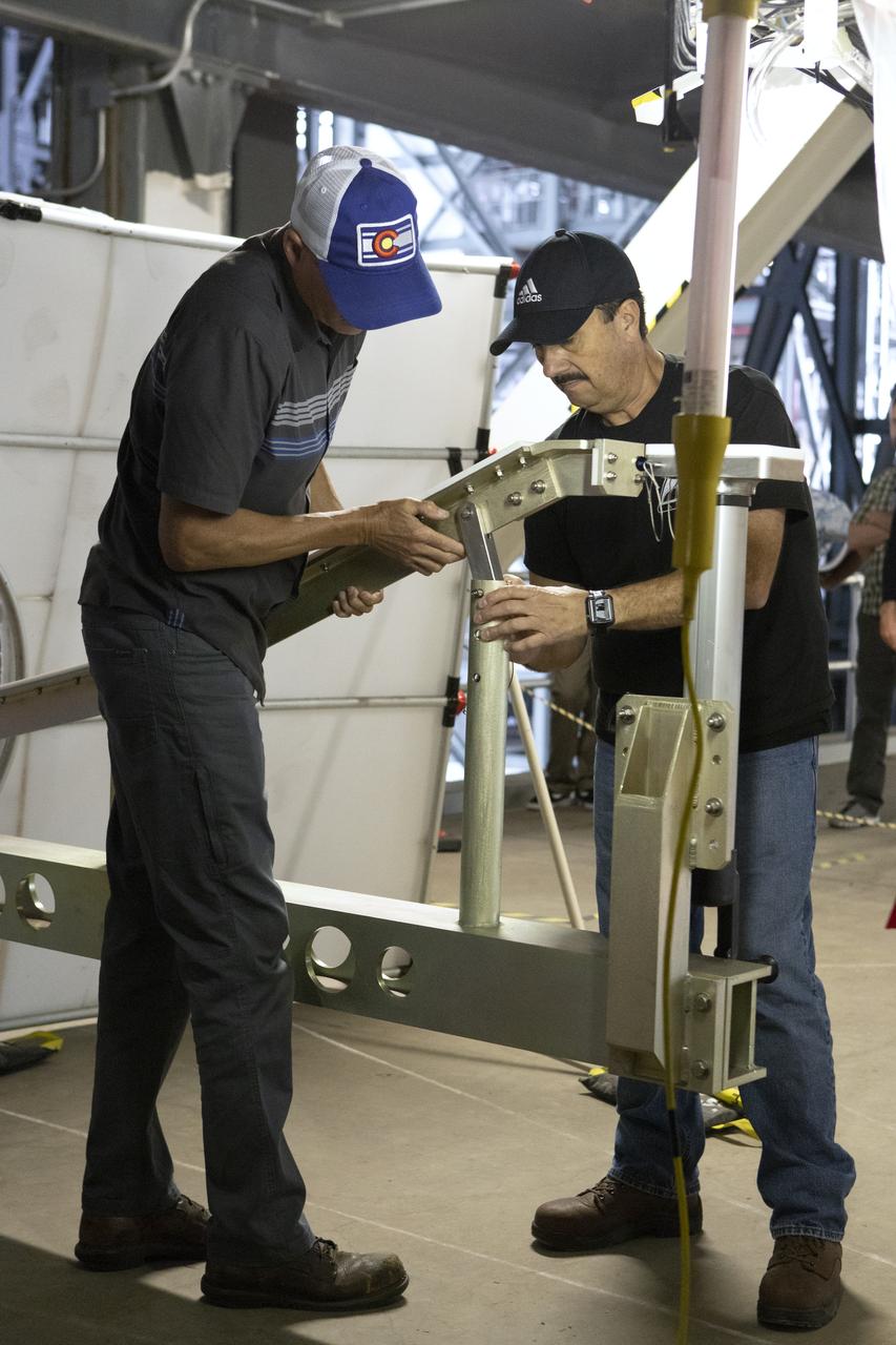
Robert Cook, a launch vehicle engineer with Millennium Engineering and Integration, talks during the Space Launch System (SLS) avionics handling tool demonstration inside Kennedy Space Center’s Vehicle Assembly Building on April 4, 2019. The demonstration showed that avionics boxes could be successfully and safely mounted into the SLS rocket’s upper stage — called the Interim Cryogenic Propulsion Stage, or ICPS — with low risk of damaging a closely located hydrazine tank. Avionics boxes include the Inertial Navigation and Control Assembly and flight batteries. Cook designed the ICPS section mockup used in the exercise.
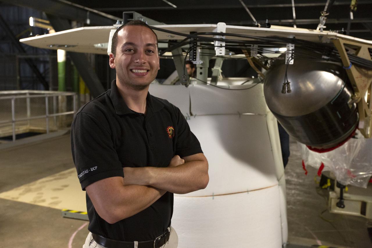
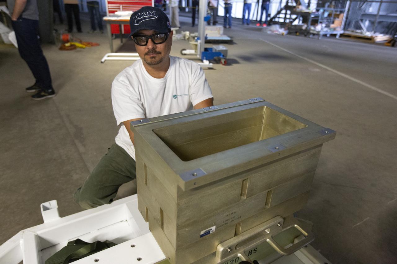
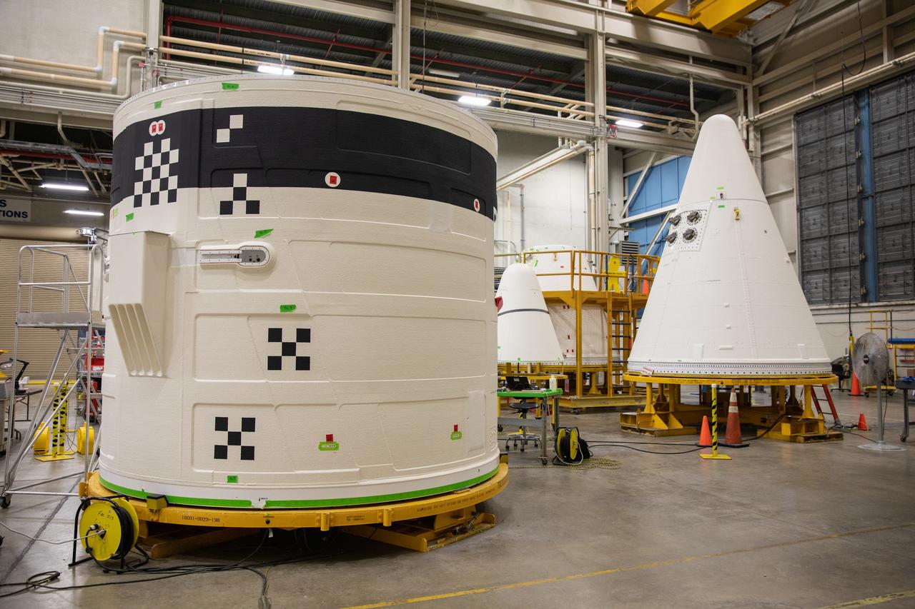
Christopher Di Taranto, a member of the mechanical structures engineering team on the Jacobs Test and Operations Contract, stands in front of an Interim Cryogenic Propulsion Stage (ICPS) mockup during the Space Launch System avionics handling tool demonstration inside Kennedy Space Center’s Vehicle Assembly Building on April 4, 2019. The demonstration showed that avionics boxes could be successfully mounted into the SLS rocket’s upper stage safely, and with low risk of damaging a closely located hydrazine tank. Avionics boxes include the Inertial Navigation and Control Assembly and flight batteries. Di Taranto led a team to quickly resolve a non-conformance issue with the tool.
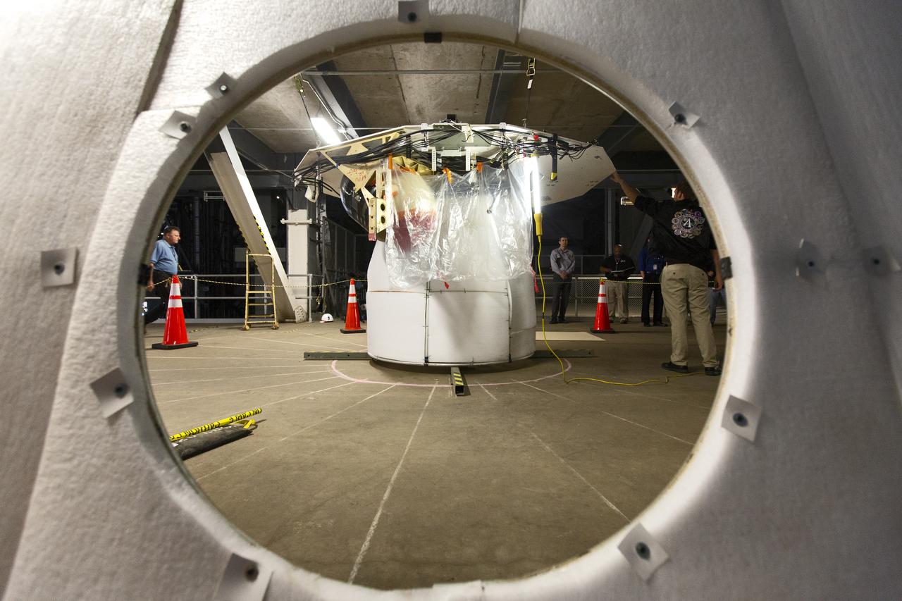
A Space Launch System (SLS) avionics handling tool demonstration takes place inside Kennedy Space Center’s Vehicle Assembly Building on April 4, 2019. The demonstration showed that avionics boxes could be successfully and safely mounted into the SLS rocket’s upper stage — called the Interim Cryogenic Propulsion Stage, or ICPS — with low risk of damaging a closely located hydrazine tank. Avionics boxes include the Inertial Navigation and Control Assembly and flight batteries. The actual installation will take place just weeks before NASA’s SLS rocket and uncrewed Orion spacecraft lift off on Exploration Mission-1 from Launch Pad 39B at Kennedy.
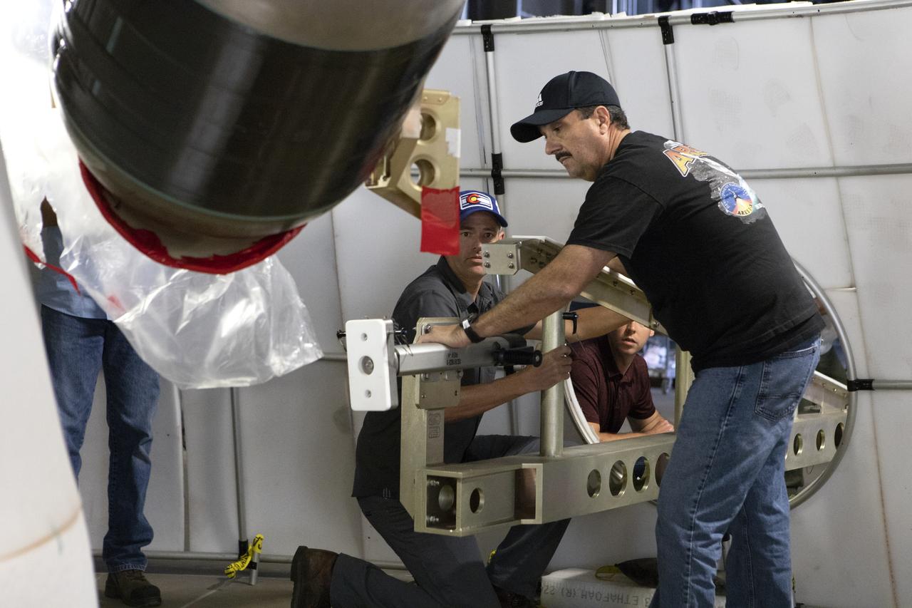
A Space Launch System (SLS) avionics handling tool demonstration takes place inside Kennedy Space Center’s Vehicle Assembly Building on April 4, 2019. The demonstration showed that avionics boxes could be successfully and safely mounted into the SLS rocket’s upper stage — called the Interim Cryogenic Propulsion Stage, or ICPS — with low risk of damaging a closely located hydrazine tank. Avionics boxes include the Inertial Navigation and Control Assembly and flight batteries. The actual installation will take place just weeks before NASA’s SLS rocket and uncrewed Orion spacecraft lift off on Exploration Mission-1 from Launch Pad 39B at Kennedy.
A Space Launch System (SLS) avionics handling tool demonstration takes place inside Kennedy Space Center’s Vehicle Assembly Building on April 4, 2019. The demonstration showed that avionics boxes could be successfully and safely mounted into the SLS rocket’s upper stage — called the Interim Cryogenic Propulsion Stage, or ICPS — with low risk of damaging a closely located hydrazine tank. Avionics boxes include the Inertial Navigation and Control Assembly and flight batteries. The actual installation will take place just weeks before NASA’s SLS rocket and uncrewed Orion spacecraft lift off on Exploration Mission-1 from Launch Pad 39B at Kennedy.
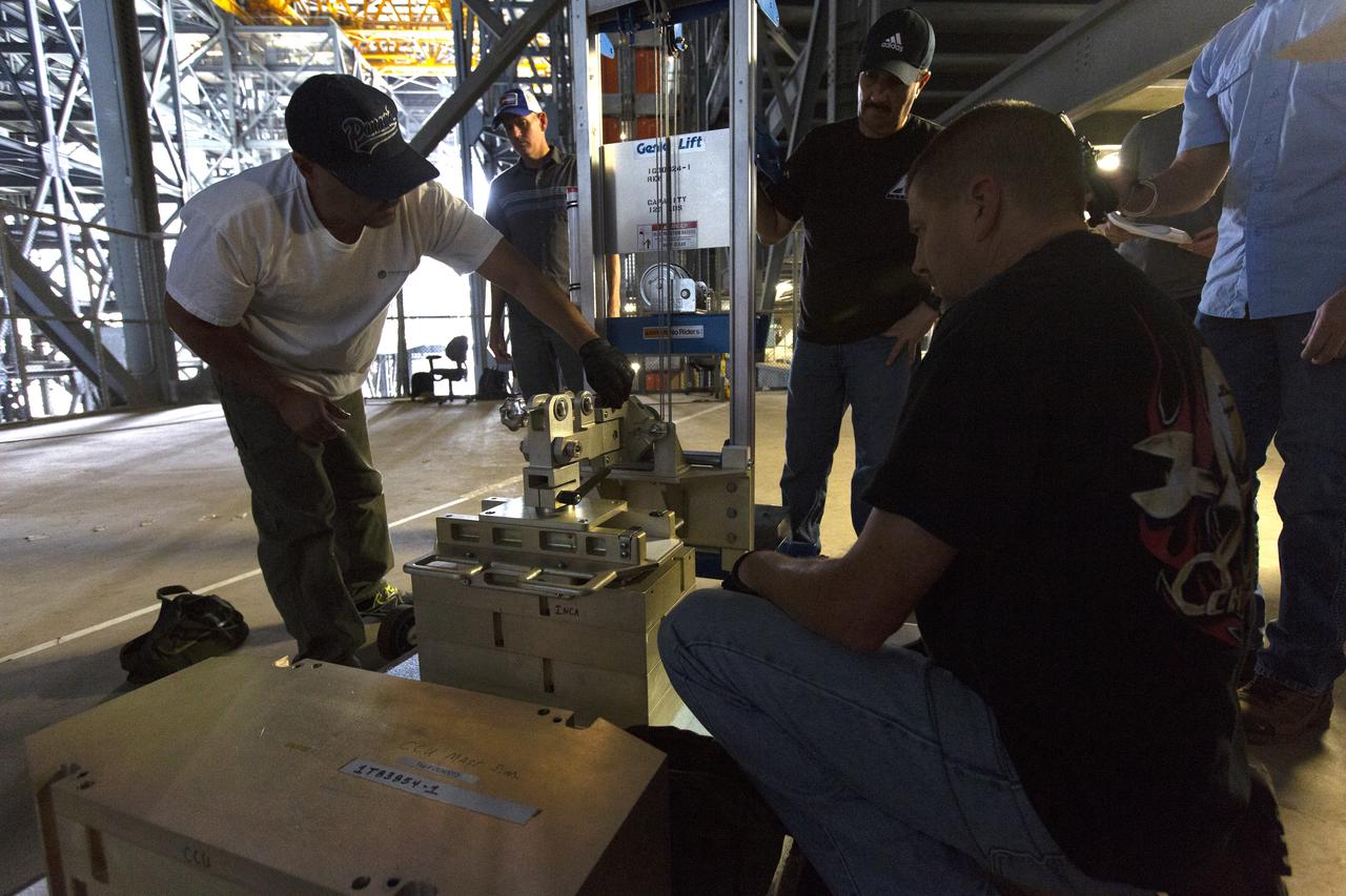
A Space Launch System (SLS) avionics handling tool demonstration takes place inside Kennedy Space Center’s Vehicle Assembly Building on April 4, 2019. The demonstration showed that avionics boxes could be successfully and safely mounted into the SLS rocket’s upper stage — called the Interim Cryogenic Propulsion Stage, or ICPS — with low risk of damaging a closely located hydrazine tank. Avionics boxes include the Inertial Navigation and Control Assembly and flight batteries. The actual installation will take place just weeks before NASA’s SLS rocket and uncrewed Orion spacecraft lift off on Exploration Mission-1 from Launch Pad 39B at Kennedy.
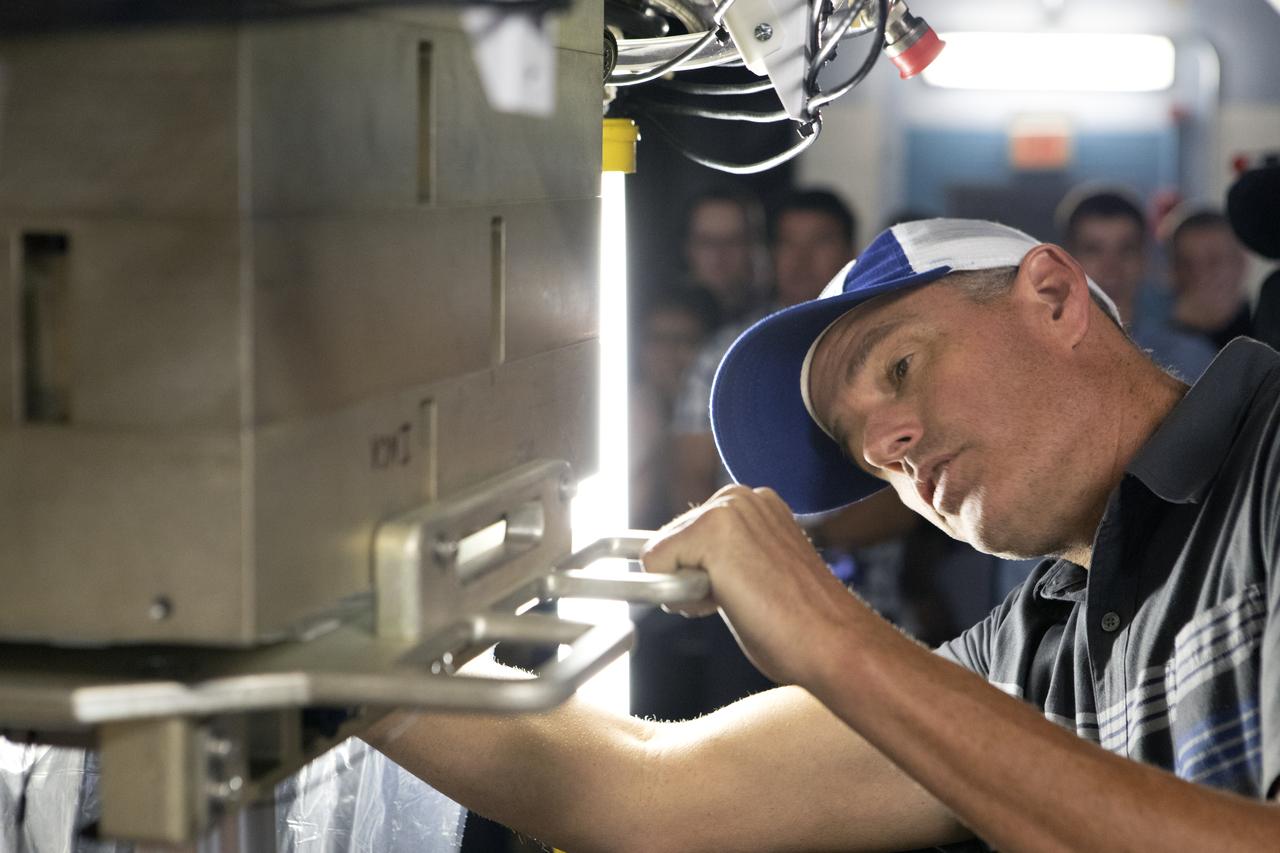
A Space Launch System (SLS) avionics handling tool demonstration takes place inside Kennedy Space Center’s Vehicle Assembly Building on April 4, 2019. The demonstration showed that avionics boxes could be successfully and safely mounted into the SLS rocket’s upper stage — called the Interim Cryogenic Propulsion Stage, or ICPS — with low risk of damaging a closely located hydrazine tank. Avionics boxes include the Inertial Navigation and Control Assembly and flight batteries. The actual installation will take place just weeks before NASA’s SLS rocket and uncrewed Orion spacecraft lift off on Exploration Mission-1 from Launch Pad 39B at Kennedy.
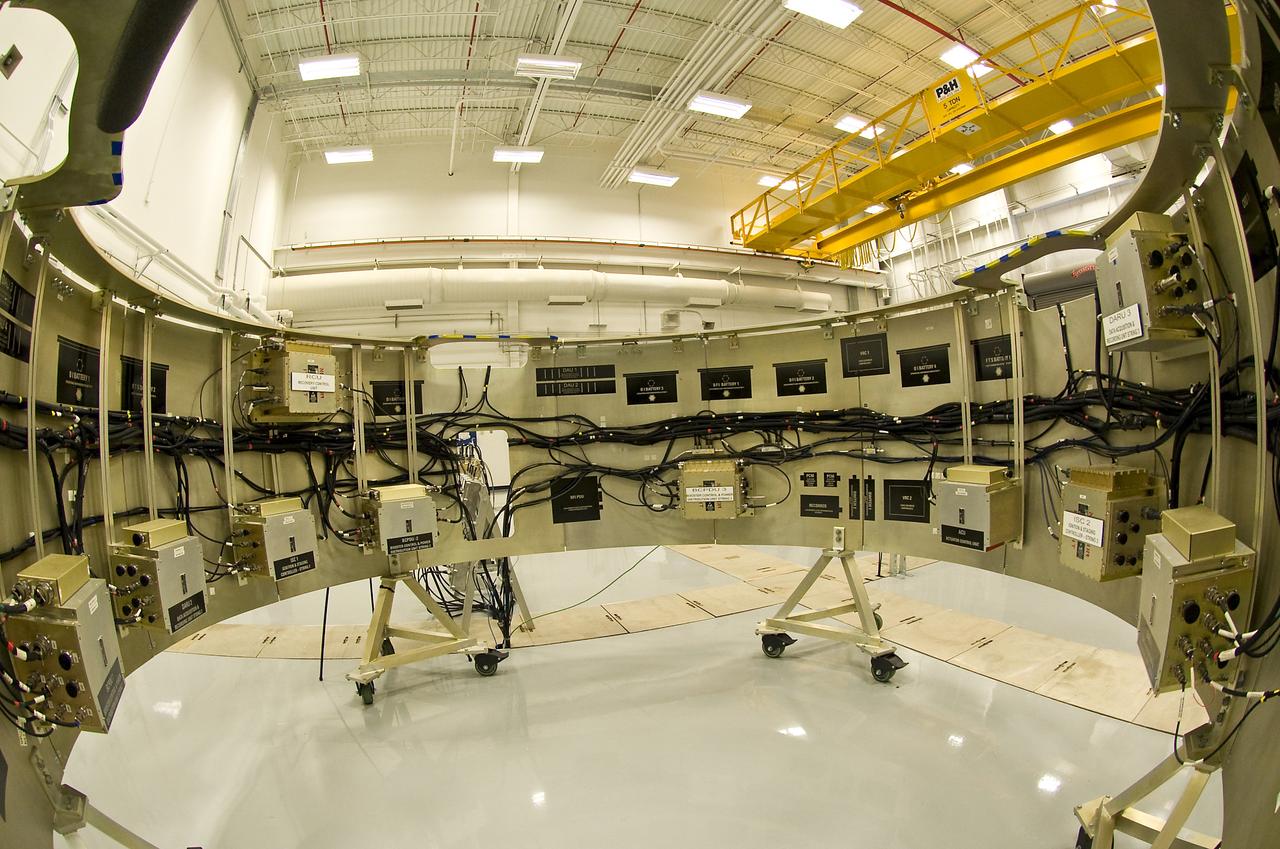
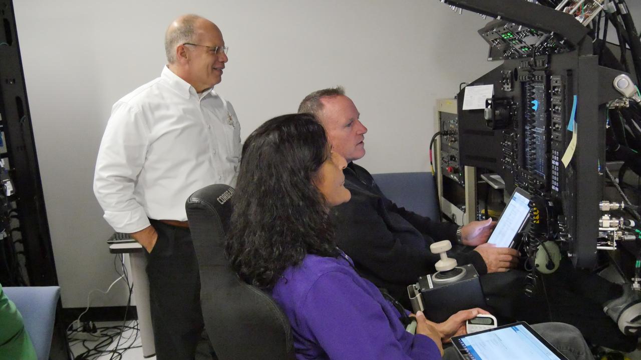
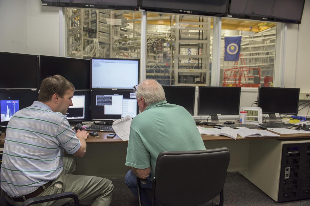
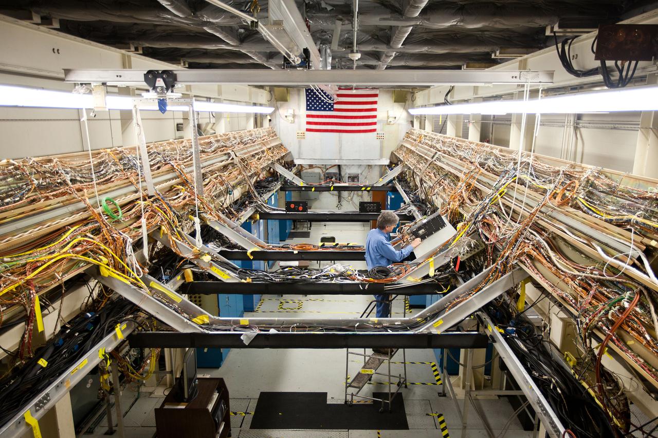
FIRST STAGE AVIONICS HARDWARE IN THE LOOP FACILITY
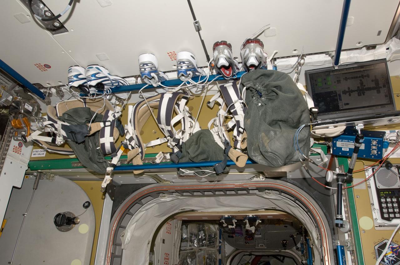
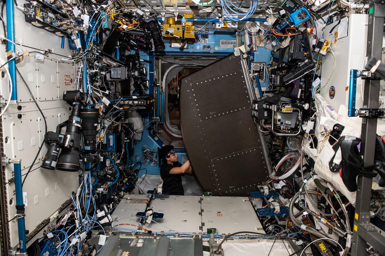
View of Avionics Rack 2 Closeout Panel with tennis shoes,in the Node 3. Photo was taken during Expedition 34.
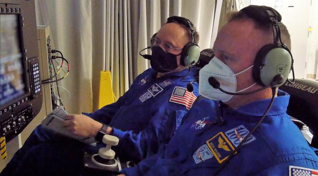
NASA astronauts Barry “Butch” Wilmore and Mike Fincke monitor the launch portion of an integrated mission dress rehearsal of Boeing’s uncrewed Orbital Flight Test-2 (OFT-2) from Boeing’s Houston-based Avionics and Software Integration Lab on Thursday, April 22, 2021. Along with NASA astronaut Nicole Mann, Wilmore and Fincke will fly aboard Boeing’s CST-100 Starliner spacecraft for the company’s Crew Flight Test (CFT) as part of NASA’s Commercial Crew Program.
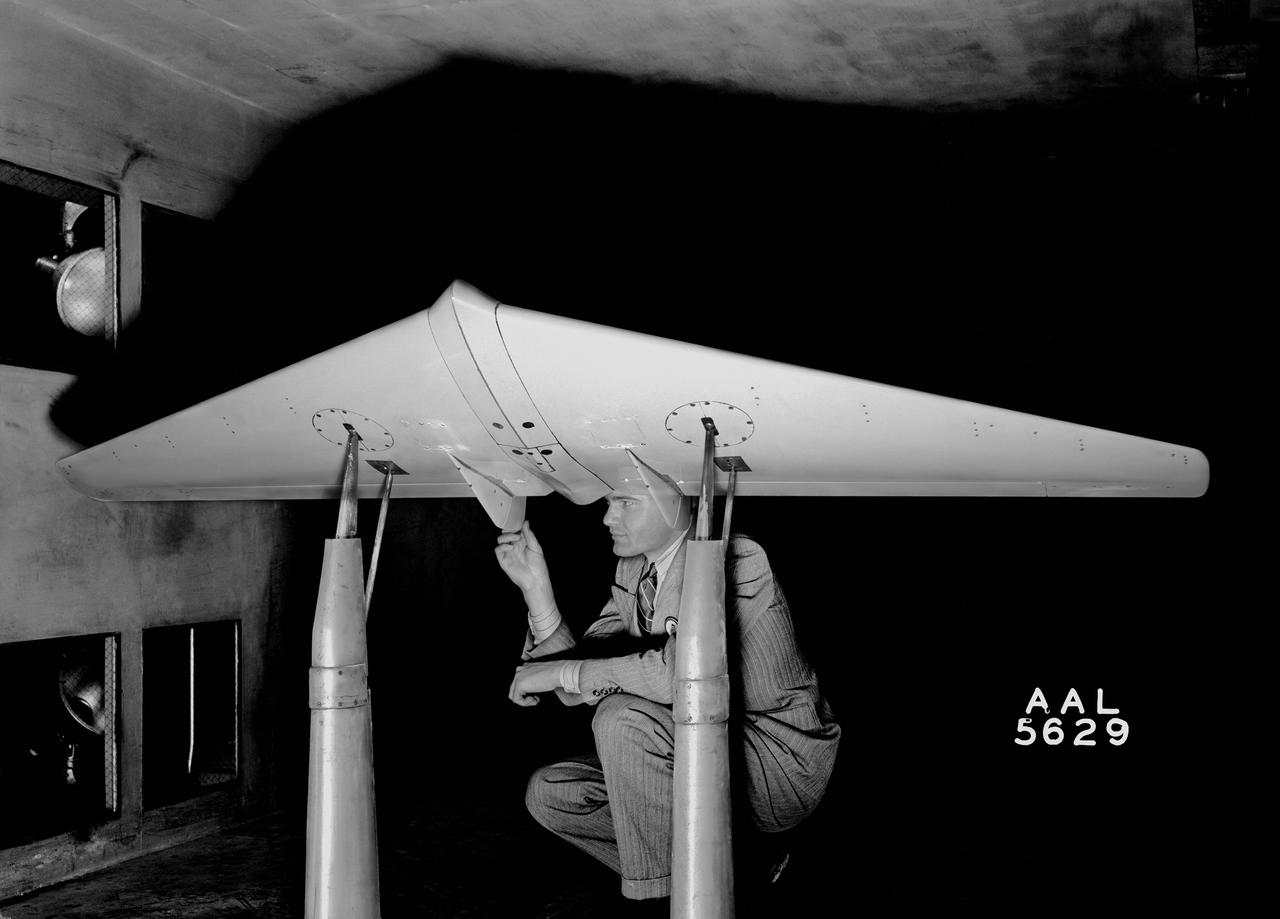
Avion MX-365 (XP-79) Wing 7x10ft w.t. @ Ames Research Center, Moffett Field, CA
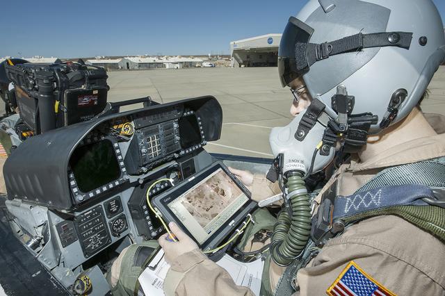
Flight Test Engineer Jacob Schaefer inspects the Cockpit Interactive Sonic Boom Display Avionics, or CISBoomDA, from the cockpit of his F-18 at NASA’s Armstrong Flight Research Center in Edwards, California.
From left, Starliner Flight Crew Integration Manager Tony Ceccacci, and NASA astronauts Barry “Butch” Wilmore and Sunita “Suni” Williams participate in a mission rehearsal at Boeing’s Avionics and Software Integration Lab in Houston.
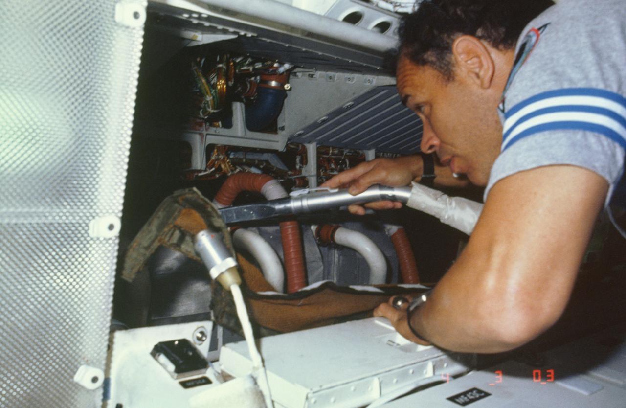
51B-13-008 (29 April-6 May 1985) --- Astronaut Frederick D. Gregory vacuums air filters in avionics bay. The 51-B pilot is physically located in the overhead area of the middeck on Challenger, but his activity is only a few meters away from the flight deck.
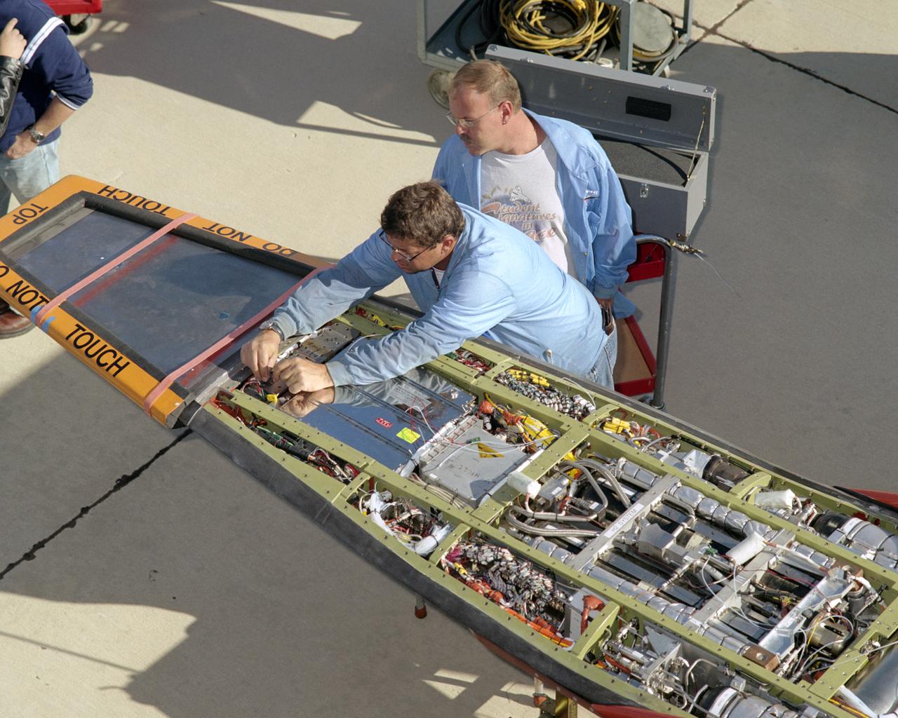
NASA avionics technicians Randy Wagner and Terry Bishop make final adjustments on the scramjet-powered X-43A before its record Mach 9.6 flight.

NASA Dryden aircraft and avionics technicians (from left) Bryan Hookland, Art Cope, Herman Rijfkogel and Jonathan Richards install the nose cone on a Phoenix missile prior to a fit check on the center's F-15B research aircraft.
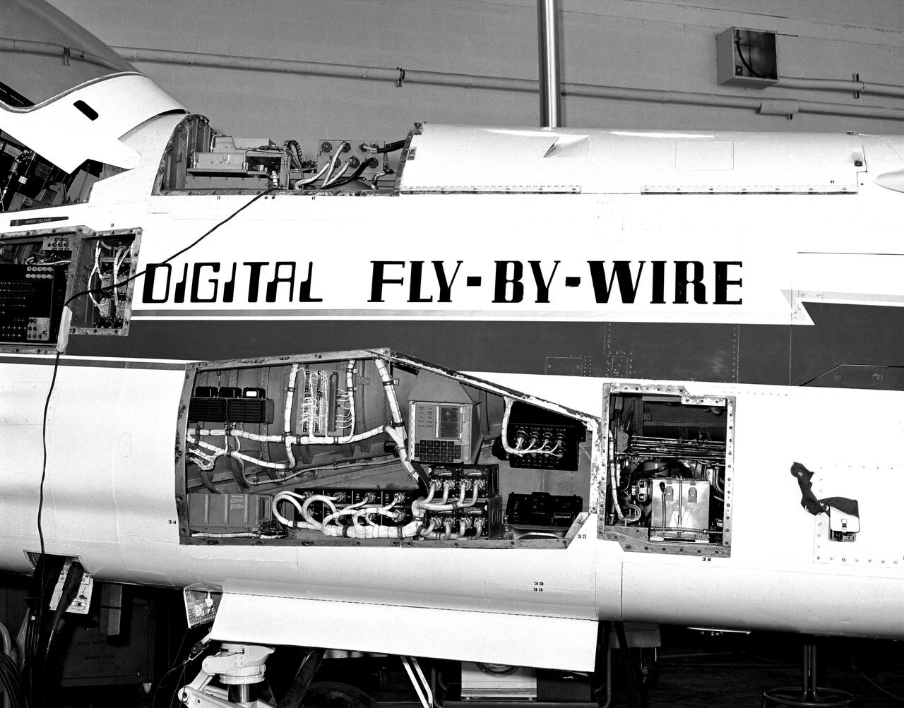
The Apollo hardware jammed into the F-8C. The computer is partially visible in the avionics bay at the top of the fuselage behind the cockpit. Note the display and keyboard unit in the gun bay. To carry the computers and other equipment, the F-8 DFBW team removed the aircraft's guns and ammunition boxes.
CAPE CANAVERAL, Fla. -- In Building 1555 at Vandenberg Air Force Base in California, workers do a fit check on the mating of the Stage 1 to Stage 2 motors for the Taurus XL rocket that will launch NASA's Orbiting Carbon Observatory, or OCO, spacecraft. At right can be seen the avionics shelf. The avionics skirt, a graphite/epoxy structure, supports the avionics shelf and carries the primary structural loads from the fairing and payload cone. The aluminum avionics shelf supports the third stage avionics. The OCO is a new Earth-orbiting mission sponsored by NASA's Earth System Science Pathfinder Program. The launch of OCO is targeted for January. Photo credit: NASA/Randy Beaudoin, VAFB
CAPE CANAVERAL, Fla. -- In Building 1555 at Vandenberg Air Force Base in California, ssembly is underway for the Taurus XL rocket that will launch NASA's Orbiting Carbon Observatory, or OCO, spacecraft. Lined up left to right are the Stage 1 and Stage 2 motors, the boattail, the avionics shelf and the Stage 3 motor. The graphite/epoxy boattail structure provides the transition from the smaller diameter of the Stage 2 motor to the larger diameter of the avionics skirt. The avionics skirt, also a graphite/epoxy structure, supports the avionics shelf and carries the primary structural loads from the fairing and payload cone. The aluminum avionics shelf supports the third stage avionics. The OCO is a new Earth-orbiting mission sponsored by NASA's Earth System Science Pathfinder Program. The launch of OCO is targeted for January. Photo credit: NASA/Randy Beaudoin, VAFB
Pegasus/Nustar, Avionics Shelf Installation
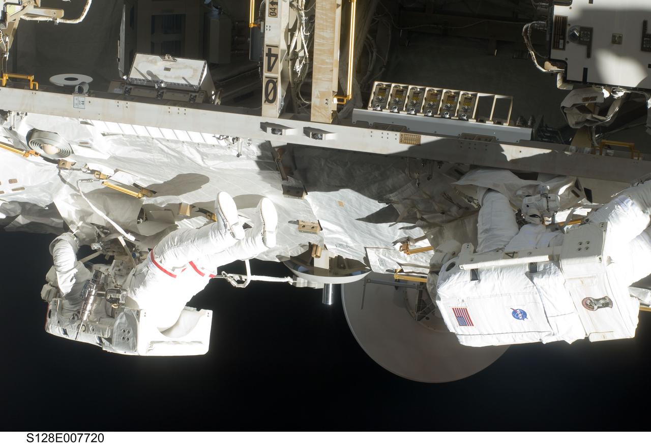
S128-E-007720 (5 Sept. 2009) --- NASA astronaut John “Danny” Olivas (left) and European Space Agency astronaut Christer Fuglesang, both STS-128 mission specialists, participate in the mission's third and final session of extravehicular activity (EVA) as construction and maintenance continue on the International Space Station. During the seven-hour, one-minute spacewalk, Olivas and Fuglesang deployed the Payload Attachment System (PAS), replaced the Rate Gyro Assembly #2, installed two GPS antennae and did some work to prepare for the installation of Node 3 next year. During connection of one of two sets of avionics cables for Node 3, one of the connectors could not be mated. This cable and connector were wrapped in a protective sleeve and safed. All other cables were mated successfully.
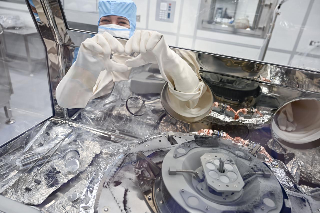
Astromaterials processor Mari Montoya shows a hand heart while working in the OSIRIS-REx canister glovebox at NASA’s Johnson Space Center in Houston. Montoya was sweeping asteroid material on the avionics deck of the OSIRIS-REx canister and was so deep in concentration that she didn’t realize the dust had formed the shape of a heart until her teammate on the other side of the glovebox pointed it out.
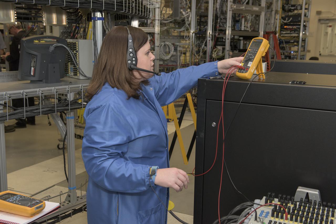
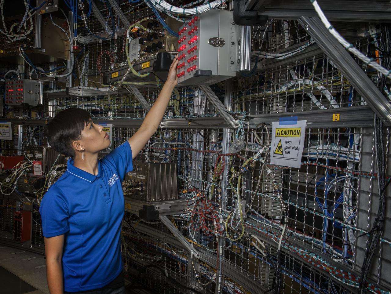
MOLLY GINTER TESTS AVIONICS SYSTEMS IN THE SYSTEMS INTEGRATION AND TEST FACILITY (SITF)
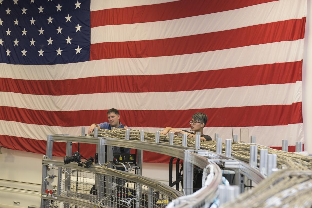
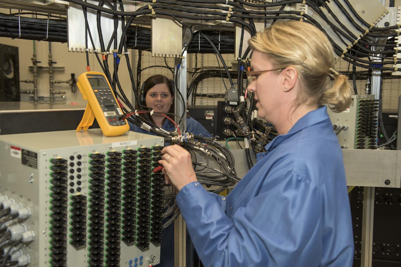
RYAN MACKRELL AND RATANA MEEKHAM INSPECT AVIONICS SYSTEMS CABLES IN THE SYSTEMS INTEGRATION AND TEST FACILITY (SITF)
JENNIFER GRAHAM AND MOLLY GINTER RUNNING TESTS OF THE AVIONICS SYSTEMS IN THE SYSTEMS INTEGRATION AND TEST FACILITY (SITF)
RYAN MACKRELL AND RATANA MEEKHAM INSPECT AVIONICS SYSTEMS CABLES IN THE SYSTEMS INTEGRATION AND TEST FACILITY (SITF).
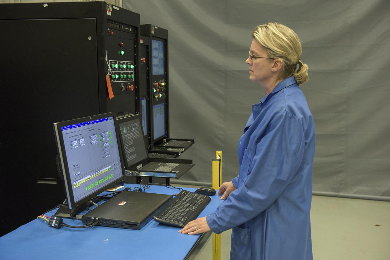
JENNIFER GRAHAM RUNNING TESTS OF THE AVIONICS SYSTEMS IN THE SYSTEMS INTEGRATION AND TEST FACILTIY (SITF)
Advanced Combustion via Microgravity Experiments, Engineering Model, EM, Avionics Package atop PI Location Simulator
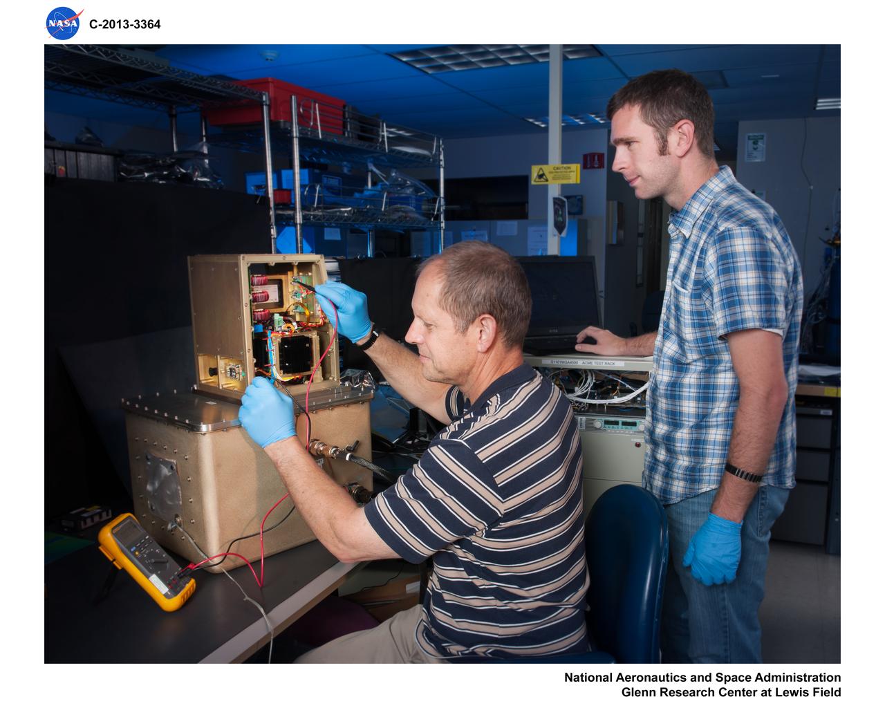
TOM SNYDER AND CHUCK ENSEY RUNNING TESTS OF THE AVIONICS SYSTEMS IN THE SYSTEMS INTEGRATION AND TEST FACILITY (SITF)
The forward skirt for one of the Space Launch System’s (SLS) two solid boosters is inside the Booster Fabrication Facility at NASA’s Kennedy Space Center in Florida on Oct. 16, 2019. Segments of the boosters are being inspected and prepared for Artemis I, the agency’s first uncrewed flight of Orion atop the SLS. The forward skirt houses booster avionics that communicate with the SLS avionics to monitor booster conditions and steer the booster exhaust nozzle.

JSC2011-E-067680 (12 July 2011) --- This is an overall view of the wiring for the simulated shuttle payload bay in the Shuttle Avionics Integration Laboratory (SAIL) at the Johnson Space Center in Houston on July 12, 2011. The laboratory is a skeletal avionics version of the shuttle that uses actual orbiter hardware and flight software. The facility even carries the official orbiter designation as Orbiter Vehicle 095. Photo credit: NASA Photo/Houston Chronicle, Smiley N. Pool
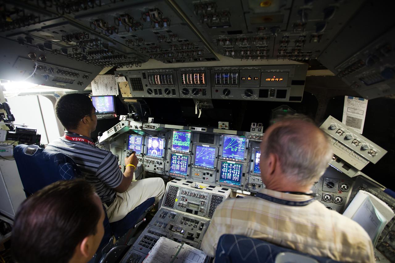
JSC2011-E-067674 (12 July 2011) --- Chris St. Julian, left, a Prairie View A&M electrical engineering major who is interning at NASA for the summer, pilots the shuttle for a simulated landing in the Shuttle Avionics Integration Laboratory (SAIL) at the Johnson Space Center in Houston, July 12, 2011. The laboratory is a skeletal avionics version of the shuttle that uses actual orbiter hardware and flight software. The facility bears the orbiter designation of Orbiter Vehicle 095. Photo credit: NASA Photo/Houston Chronicle, Smiley N. Pool
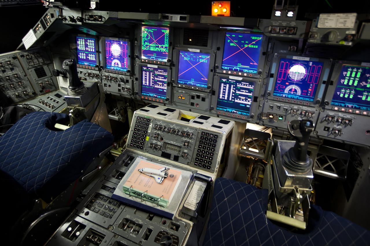
JSC2011-E-067676 (12 July 2011) --- A close-up view of controls and displays on the forward flight deck of OV-095 in the Shuttle Avionics Integration Laboratory (SAIL) at the Johnson Space Center in Houston, July 12, 2011. The laboratory is a skeletal avionics version of the shuttle that uses actual orbiter hardware and flight software. Photo credit: NASA Photo/Houston Chronicle, Smiley N. Pool
JSC2011-E-067679 (12 July 2011) --- This is an overall view of the wiring for the simulated shuttle payload bay in the Shuttle Avionics Integration Laboratory (SAIL) at the Johnson Space Center in Houston on July 12, 2011. The laboratory is a skeletal avionics version of the shuttle that uses actual orbiter hardware and flight software. The facility even carries the official orbiter designation as Orbiter Vehicle 095. Photo credit: NASA Photo/Houston Chronicle, Smiley N. Pool
JSC2011-E-067682 (12 July 2011) --- Chief engineer Frank Svrecek pauses in the Shuttle Avionics Integration Laboratory (SAIL) at the Johnson Space Center in Houston July 12, 2011. The laboratory is a skeletal avionics version of the shuttle that uses actual orbiter hardware and flight software. The facility is referred to as Orbiter Vehicle 095. Photo credit: NASA Photo/Houston Chronicle, Smiley N. Pool
A forward skirt and two nose cones for the Space Launch System’s (SLS) two solid boosters are in view inside the Booster Fabrication Facility at NASA’s Kennedy Space Center in Florida on Oct. 16, 2019. Segments of the boosters are being inspected and prepared for Artemis I, the agency’s first uncrewed flight of Orion atop the SLS. The forward skirt houses booster avionics that communicate with the SLS avionics to monitor booster conditions and steer the booster exhaust nozzle. The nose cone, along with a frustrum, will serve as the aerodynamic fairing for the boosters during launch.

NASA test pilot, Nils Larson, inspects the X-59 cockpit displays and lighting system during system checkouts. The External Vision System (XVS) is displayed on the top screen, and the avionics flight displays, which can show navigation information or aircraft status, are shown on the bottom two screens.
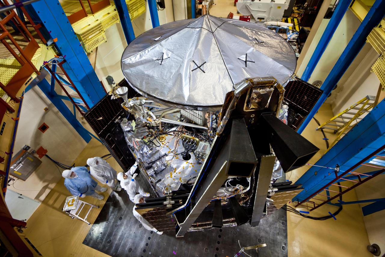
This image shows NASA Juno spacecraft undergoing environmental testing at Lockheed Martin Space Systems on Jan. 26, 2011. All 3 solar array wings are installed and stowed, and the large high-gain antenna is in place on the top of the avionics vault.
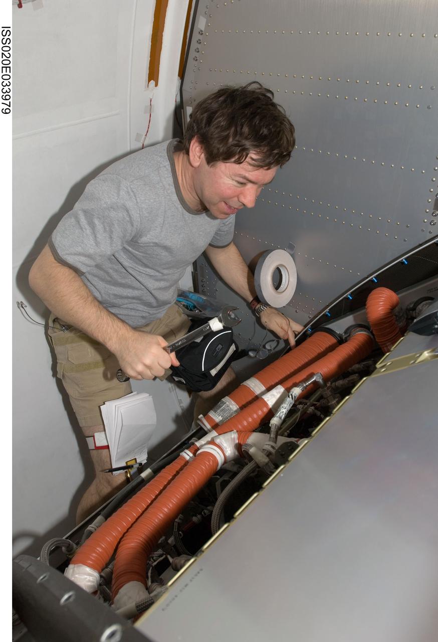
ISS020-E-033979 (25 Aug. 2009) --- NASA astronaut Michael Barratt, Expedition 20 flight engineer, works with the Crew Health Care System (CHeCS) rack in the Kibo laboratory of the International Space Station.

LOUISVILLE, Colo. – During NASA's Commercial Crew Development Round 2 CCDev2) activities for the Commercial Crew Program CCP, Sierra Nevada Corp. SNC built a Simulator and Avionics Laboratory to help engineers evaluate the Dream Chaser's characteristics during the piloted phases of flight. Located at Sierra Nevada’s Space Systems facility in Louisville, Colo., it consists of a physical cockpit and integrated simulation hardware and software. The simulator is linked to the Vehicle Avionics Integration Laboratory, or VAIL, which serves as a platform for Dream Chaser avionics development, engineering testing and integration. VAIL also will also be used for verification and validation of avionics and software. Sierra Nevada is one of seven companies NASA entered into Space Act Agreements SAAs with during CCDev2 to aid in the innovation and development of American-led commercial capabilities for crew transportation and rescue services to and from the International Space Station and other low Earth orbit destinations. For information about CCP, visit www.nasa.gov/commercialcrew. Photo credit: Sierra Nevada Corp.
NASA’s Armstrong Flight Research Center ER-2 #809 high-altitude aircraft maintained by avionics technician Gregory Bantalin for Dynamics and Chemistry of the Summer Stratosphere (DCOTSS) science flights.
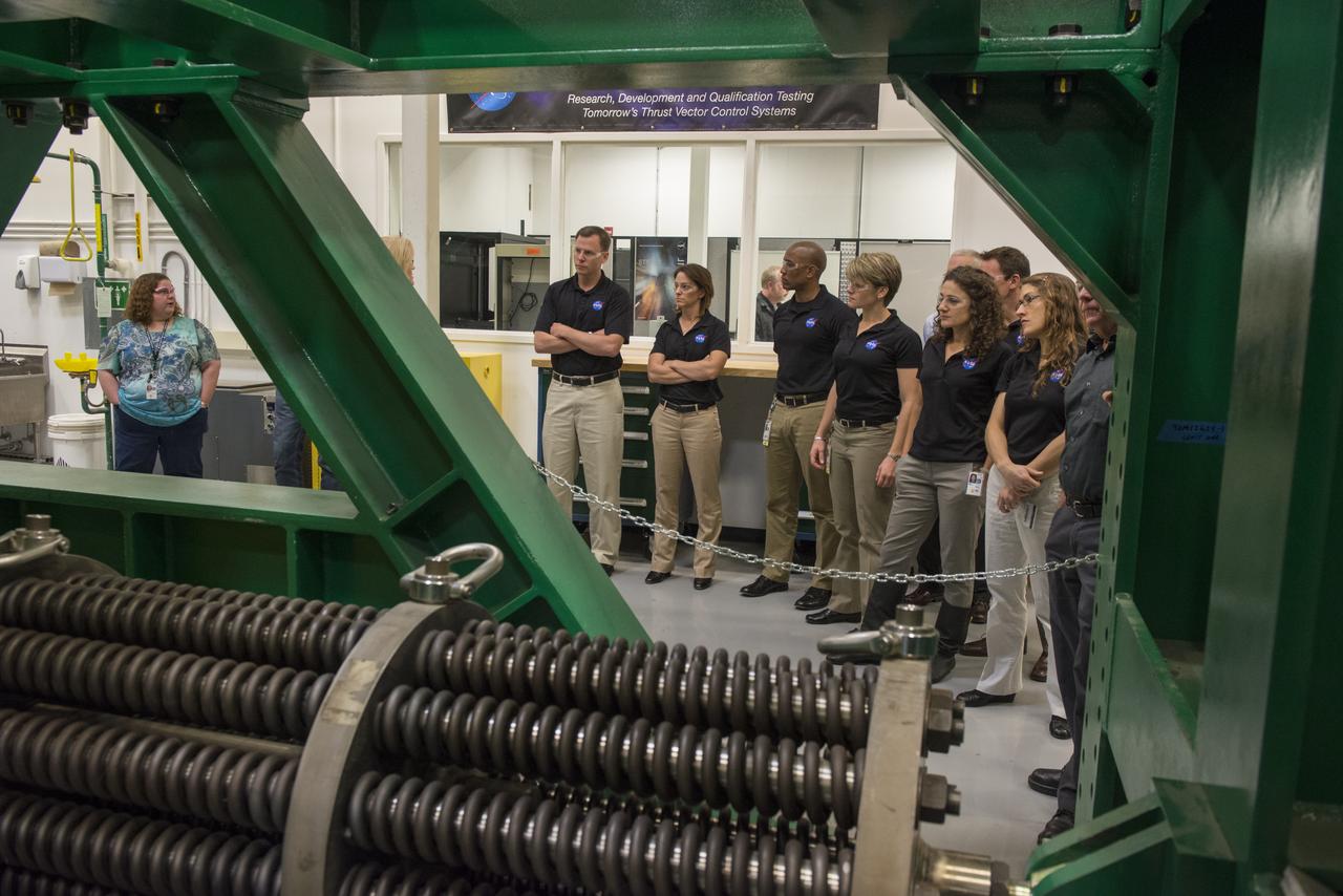
THE 2013 ASTRONAUT CANDIDATE CLASS VISITED THE THRUST VECTOR CONTROL TEST LAB AT MARSHALL'S PROPULSION RESEARCH DEVELOPMENT LABORATORY WHERE ENGINEERS ARE DEVELOPING AND TESTING THE SPACE LAUNCH SYSTEM'S GUIDANCE, NAVIGATION AND CONTROL SOFTWARE AND AVIONICS HARDWARE.
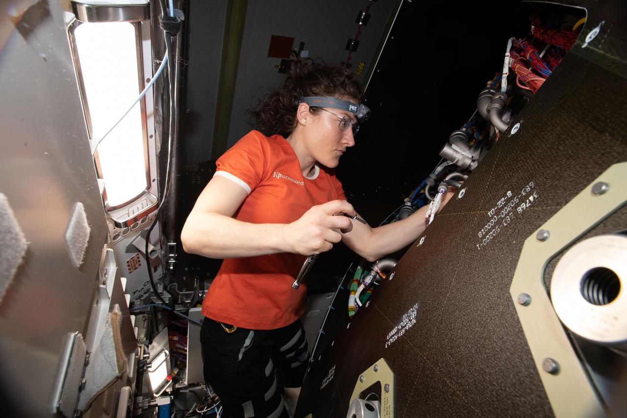
iss059e009964 (April 4, 2018) --- NASA astronaut and Expedition 59 Flight Engineer Christina Koch removes audio hardware from an avionics rack inside the Tranquility module.
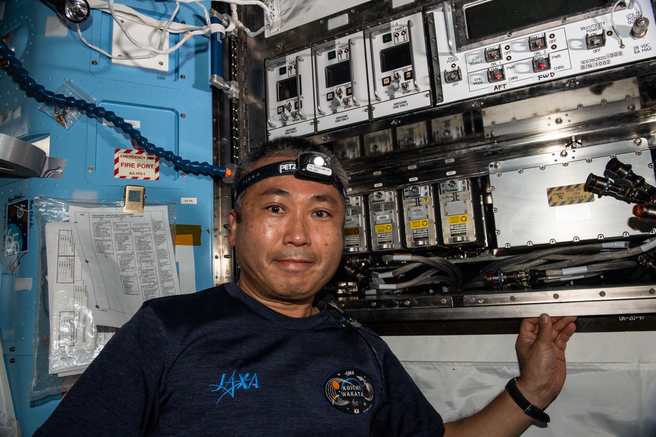
iss068e017570 (Oct. 19, 2022) --- Expedition 68 Flight Engineer Koichi Wakata of the Japan Aerospace Exploration Agency (JAXA) works in the U.S. Quest airlock swapping electronics components and checking cable connections inside an avionics rack.
RATANA MEEKHAM, AN ELECTRICAL INTEGRATION TECHNICIAN FOR QUALIS CORP. OF HUNTSVILLE, ALABAMA, HELPS TEST AVIONICS -- COMPLEX VEHICLE SYSTEMS ENABLING NAVIGATION, COMMUNICATIONS AND OTHER FUNCTIONS CRITICAL TO HUMAN SPACEFLIGHT -- FOR THE SPACE LAUNCH SYSTEM PROGRAM AT NASA’S MARSHALL SPACE FLIGHT CENTER IN HUNTSVILLE, ALABAMA. HER WORK SUPPORTS THE NASA ENGINEERING & SCIENCE SERVICES AND SKILLS AUGMENTATION CONTRACT LED BY JACOBS ENGINEERING OF HUNTSVILLE. MEEKHAM WORKS FULL-TIME AT MARSHALL WHILE FINISHING HER ASSOCIATE'S DEGREE IN MACHINE TOOL TECHNOLOGY AT CALHOUN COMMUNITY COLLEGE IN DECATUR, ALABAMA. THE SPACE LAUNCH SYSTEM, NASA’S NEXT HEAVY-LIFT LAUNCH VEHICLE, IS THE WORLD’S MOST POWERFUL ROCKET, SET TO FLY ITS FIRST UNCREWED LUNAR ORBITAL MISSION IN 2018. ITS FIRST.
RATANA MEEKHAM, AN ELECTRICAL INTEGRATION TECHNICIAN FOR QUALIS CORP. OF HUNTSVILLE, ALABAMA, HELPS TEST AVIONICS -- COMPLEX VEHICLE SYSTEMS ENABLING NAVIGATION, COMMUNICATIONS AND OTHER FUNCTIONS CRITICAL TO HUMAN SPACEFLIGHT -- FOR THE SPACE LAUNCH SYSTEM PROGRAM AT NASA’S MARSHALL SPACE FLIGHT CENTER IN HUNTSVILLE, ALABAMA. HER WORK SUPPORTS THE NASA ENGINEERING & SCIENCE SERVICES AND SKILLS AUGMENTATION CONTRACT LED BY JACOBS ENGINEERING OF HUNTSVILLE. MEEKHAM WORKS FULL-TIME AT MARSHALL WHILE FINISHING HER ASSOCIATE'S DEGREE IN MACHINE TOOL TECHNOLOGY AT CALHOUN COMMUNITY COLLEGE IN DECATUR, ALABAMA. THE SPACE LAUNCH SYSTEM, NASA’S NEXT HEAVY-LIFT LAUNCH VEHICLE, IS THE WORLD’S MOST POWERFUL ROCKET, SET TO FLY ITS FIRST UNCREWED LUNAR ORBITAL MISSION IN 2018. ITS FIRST.
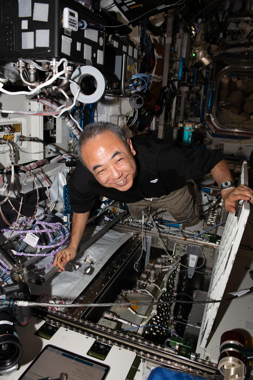
iss070e014709 (Oct. 27, 2023) --- JAXA (Japan Aerospace Exploration Agency) astronaut and Expedition 70 Flight Engineer Satoshi Furukawa replaces hardware inside an avionics rack located aboard the International Space Station's Destiny laboratory module.
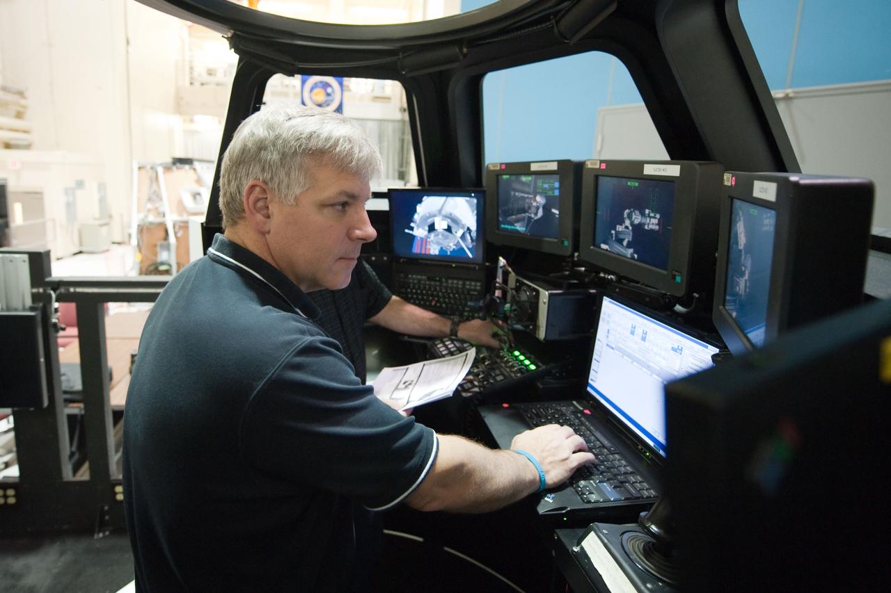
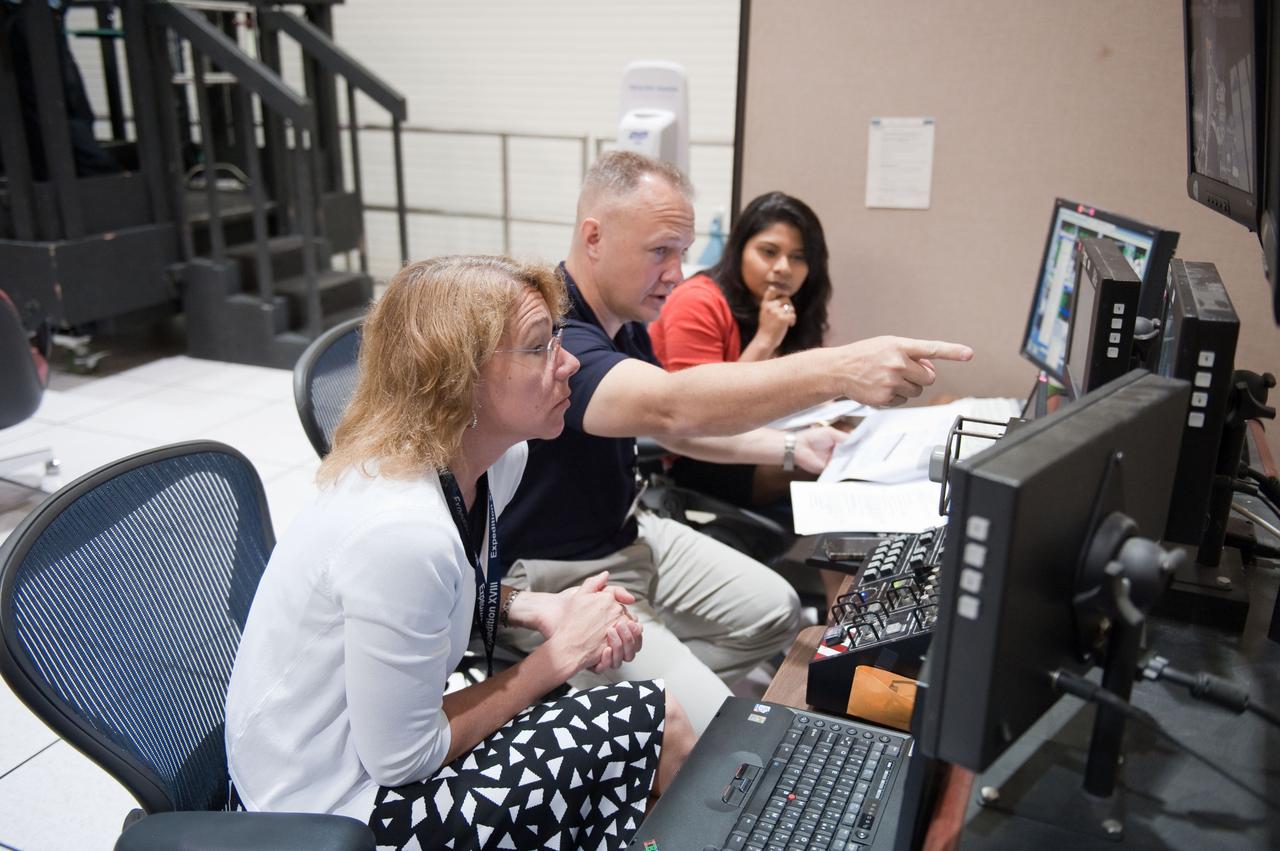
JSC2011-E-028158 (23 March 2011) --- NASA astronaut Greg H. Johnson, STS-134 pilot, participates in an exercise in the systems engineering simulator in the Avionics Systems Laboratory at NASA's Johnson Space Center. Photo credit: NASA or National Aeronautics and Space Administration

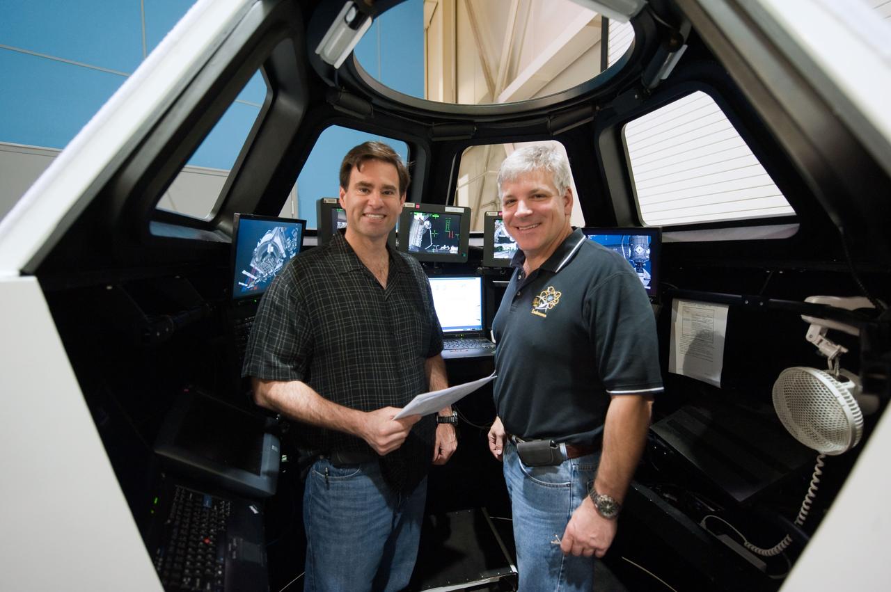
JSC2011-E-028150 (23 March 2011) --- NASA astronauts Doug Hurley, STS-135 pilot; and Sandy Magnus (foreground), mission specialist, participate in an exercise in the systems engineering simulator in the Avionics Systems Laboratory at NASA's Johnson Space Center. Photo credit: NASA or National Aeronautics and Space Administration
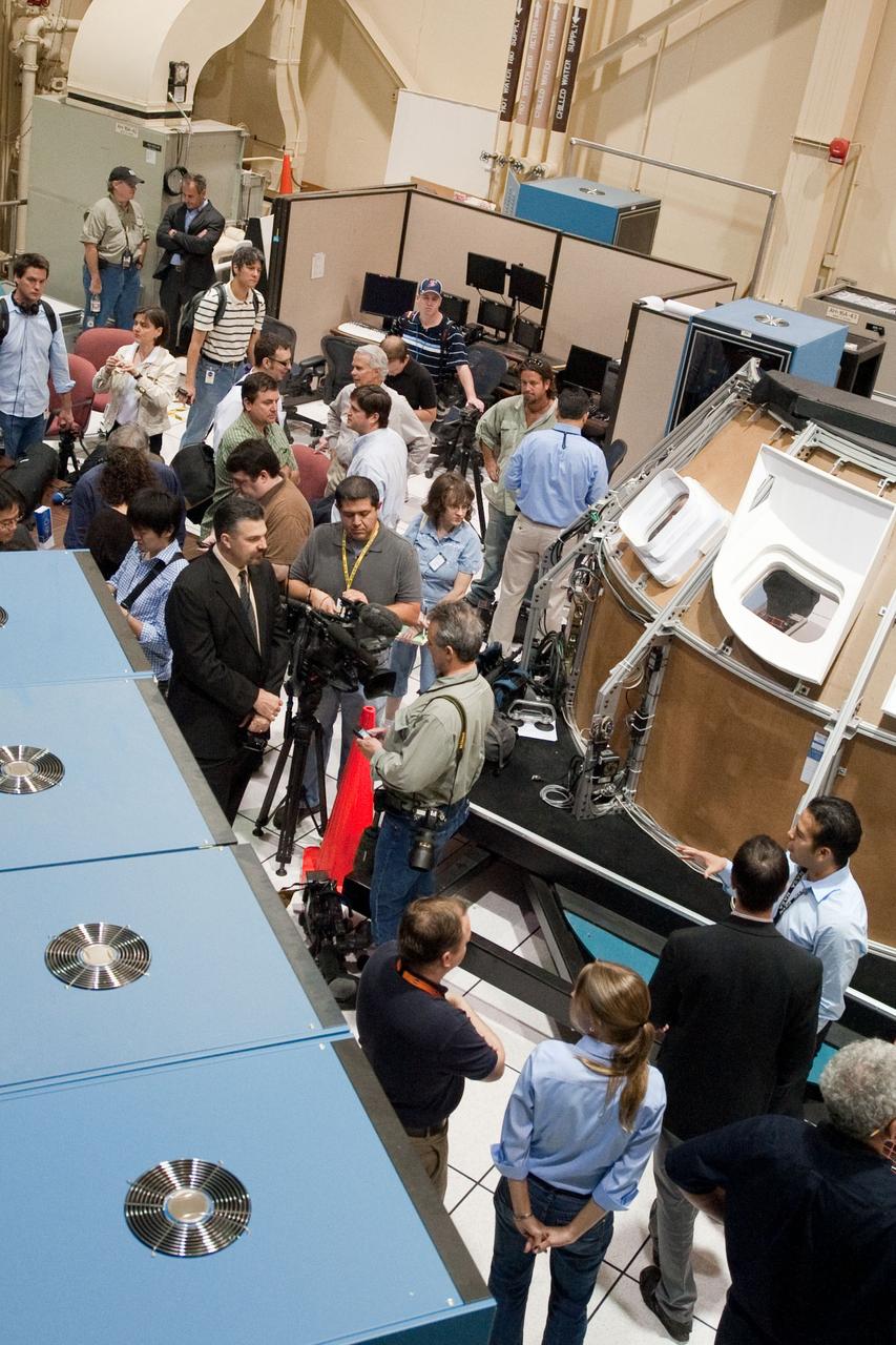
JSC2011-E-028128 (23 March 2011) --- News media representatives and NASA personnel are pictured during an STS-135 media day event in the Avionics Systems Laboratory at NASA's Johnson Space Center. Photo credit: NASA or National Aeronautics and Space Administration
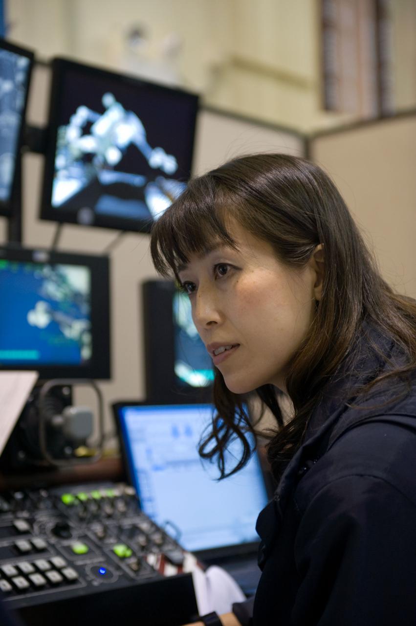
JSC2010-E-009784 (15 Jan. 2010) --- Japan Aerospace Exploration Agency (JAXA) astronaut Naoko Yamazaki, STS-131 mission specialist, participates in a simulation exercise using the Space Station Remote Manipulator System (SSRMS) simulator in the Avionics Systems Laboratory at NASA?s Johnson Space Center.
JSC2011-E-028160 (23 March 2011) --- NASA astronauts Greg H. Johnson (right), STS-134 pilot; and Greg Chamitoff, mission specialist, are pictured during an exercise in the systems engineering simulator in the Avionics Systems Laboratory at NASA's Johnson Space Center. Photo credit: NASA or National Aeronautics and Space Administration
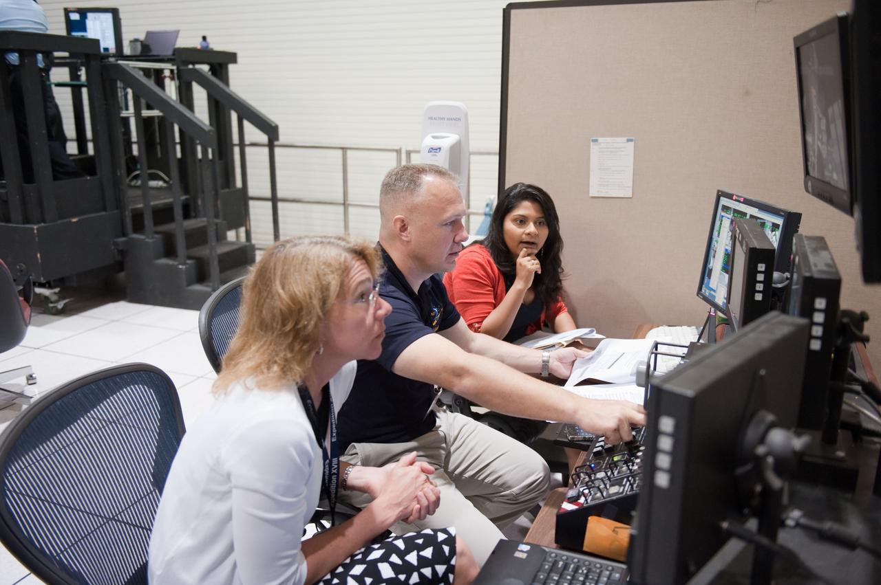
JSC2011-E-028153 (23 March 2011) --- NASA astronauts Doug Hurley, STS-135 pilot; and Sandy Magnus (foreground), mission specialist, participate in an exercise in the systems engineering simulator in the Avionics Systems Laboratory at NASA's Johnson Space Center. Photo credit: NASA or National Aeronautics and Space Administration
iss067e184990 (July 12, 2022) --- Expedition 67 Flight Engineer and NASA astronaut Jessica Watkins replaces components on the Major Constituents Analyzer (MCA) in the U.S. Destiny laboratory module's Avionic Rack. The MCA is a life support device ensures oxygen and carbon dioxide levels remain safe aboard the International Space Station.
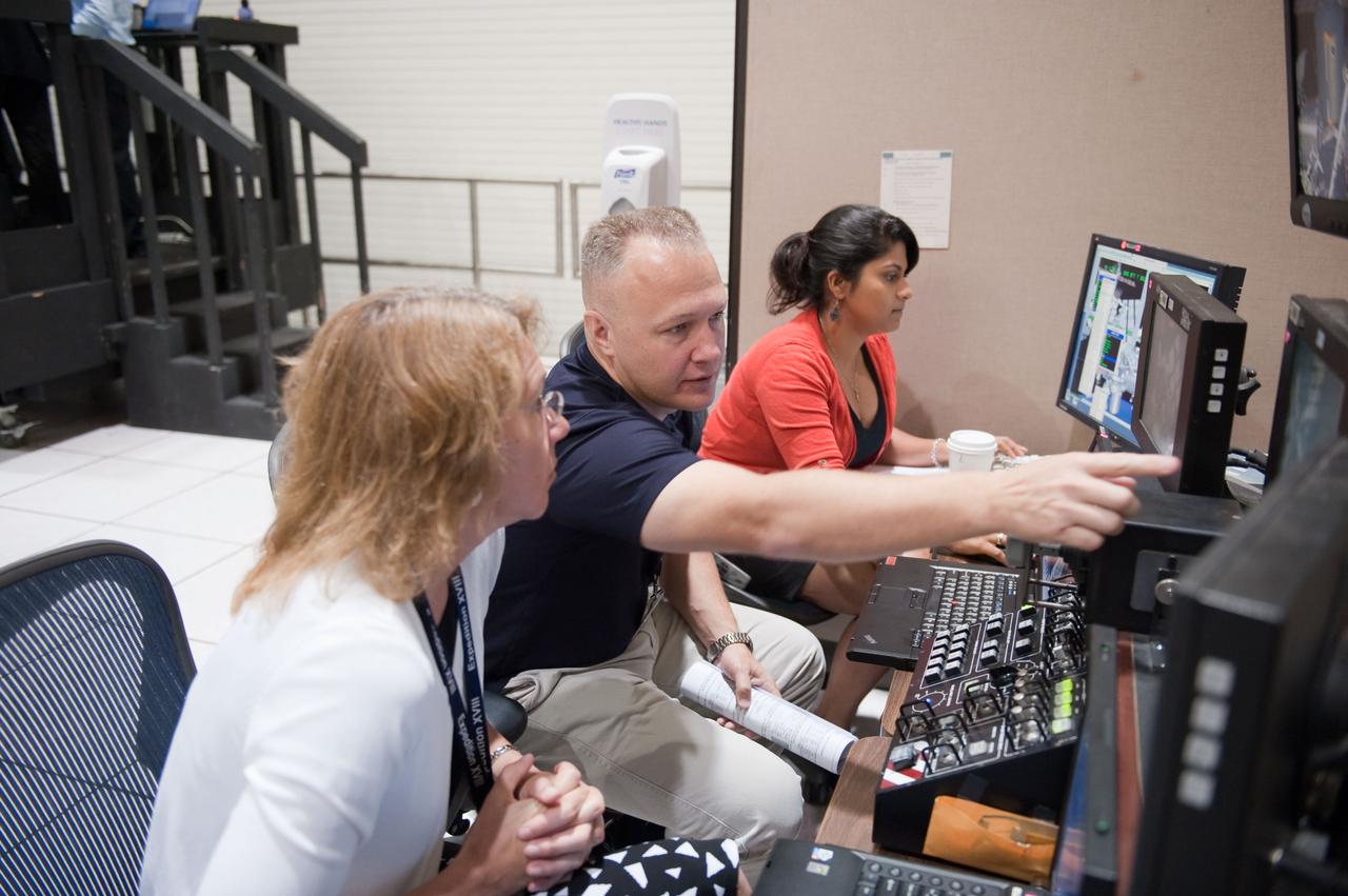
JSC2011-E-028151 (23 March 2011) --- NASA astronauts Doug Hurley, STS-135 pilot; and Sandy Magnus (foreground), mission specialist, participate in an exercise in the systems engineering simulator in the Avionics Systems Laboratory at NASA's Johnson Space Center. Photo credit: NASA or National Aeronautics and Space Administration
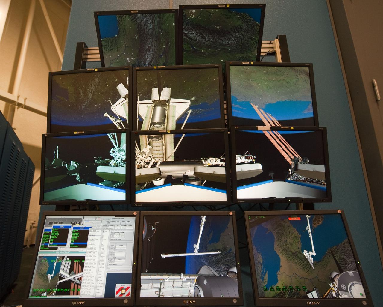
JSC2010-E-090701 (8 June 2010) --- Several computer monitors are featured in this image photographed during an STS-133 exercise in the systems engineering simulator in the Avionics Systems Laboratory at NASA's Johnson Space Center. The facility includes moving scenes of full-sized International Space Station components over a simulated Earth.
JSC2011-E-028122 (23 March 2011) --- NASA astronauts Doug Hurley, STS-135 pilot; and Sandy Magnus (foreground), mission specialist, participate in an exercise in the systems engineering simulator in the Avionics Systems Laboratory at NASA's Johnson Space Center. Photo credit: NASA or National Aeronautics and Space Administration
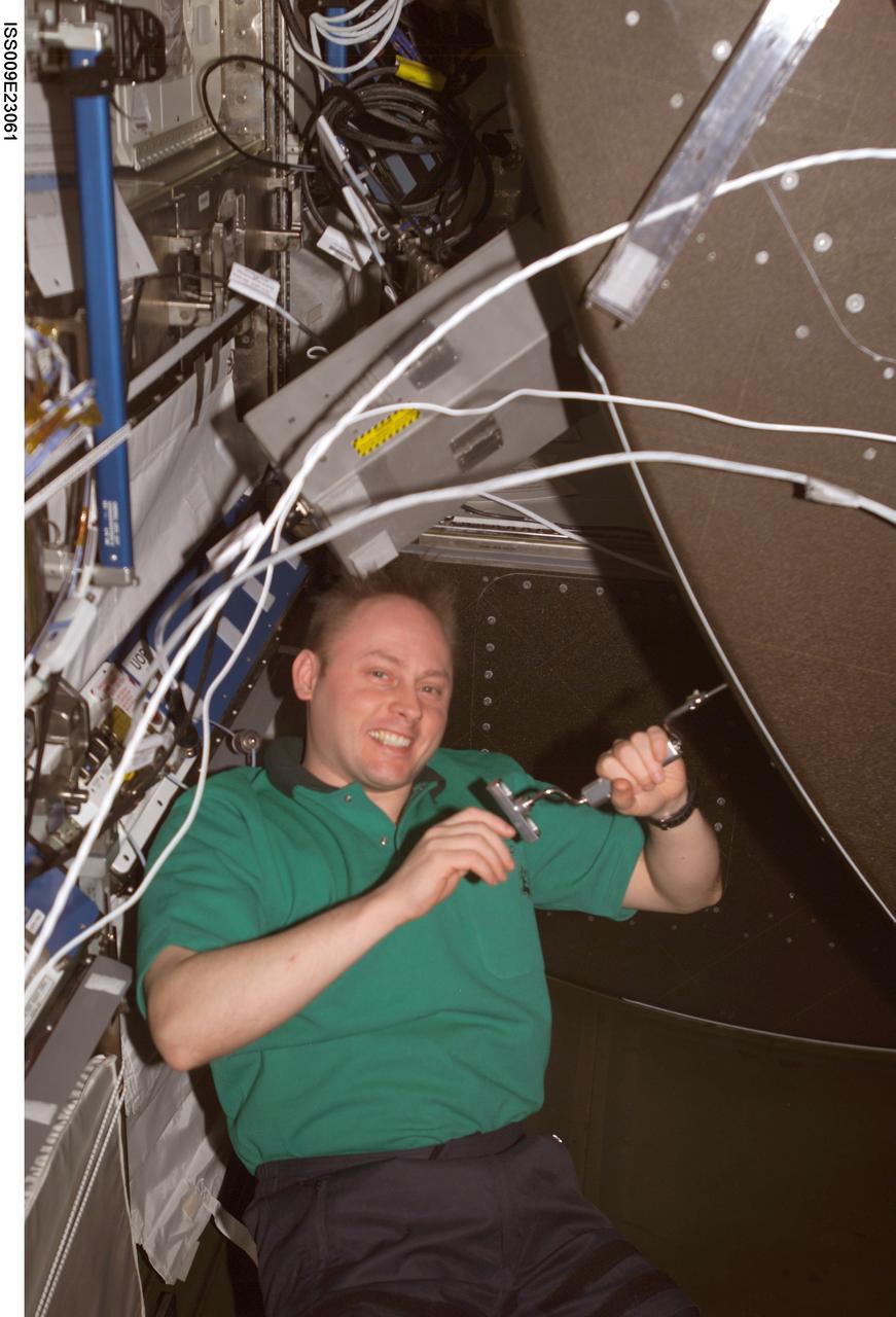
ISS009-E-23061 (16 September 2004) --- Astronaut Edward M. (Mike) Fincke, Expedition 9 NASA ISS science officer and flight engineer, uses a drill to unfasten a panel on the CHeCS Rack in the Destiny laboratory of the International Space Station (ISS). Fincke was about to perform an inspection of the Avionics Air Assembly.
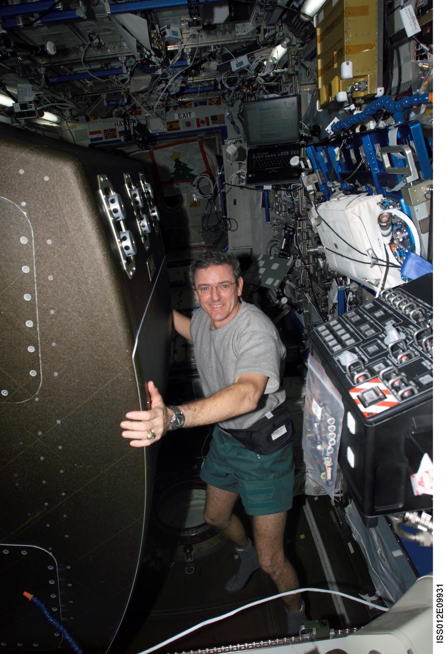
ISS012-E-09931 (1 December 2005) --- Astronaut William S. (Bill) McArthur Jr., Expedition 12 commander and NASA space station science officer, rotates the Crew Health Care System (CHeCS) rack back into position after cleaning the Avionics Air Assembly fan in the Destiny laboratory of the International Space Station.
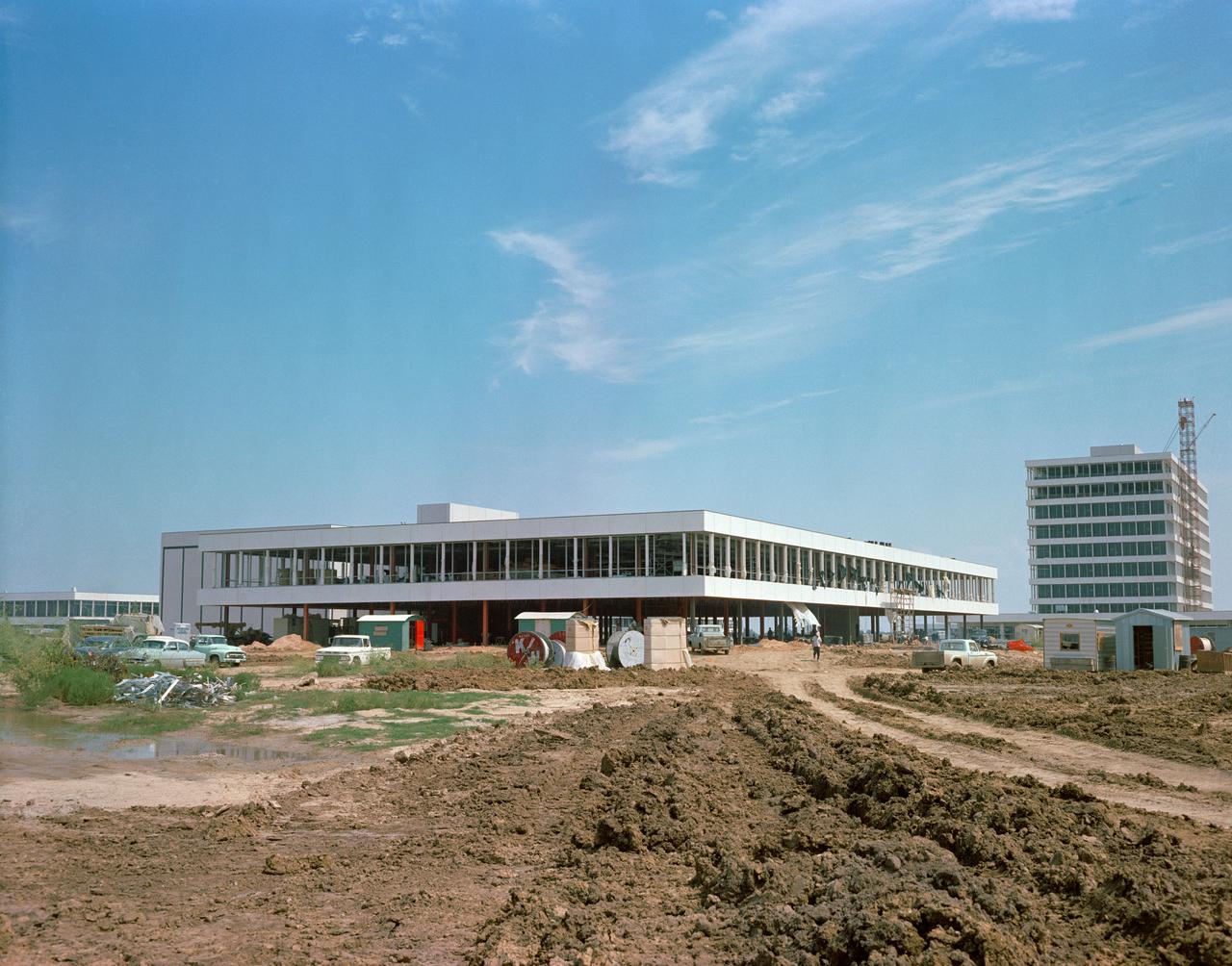
S63-17423 (25 Sept. 1963) --- This easterly view documents early construction of the Manned Spacecraft Center in September of 1963. The Avionics Systems Laboratory (Building 16) is in the foreground and the Project Management Building is see in the right background. Photo credit: NASA
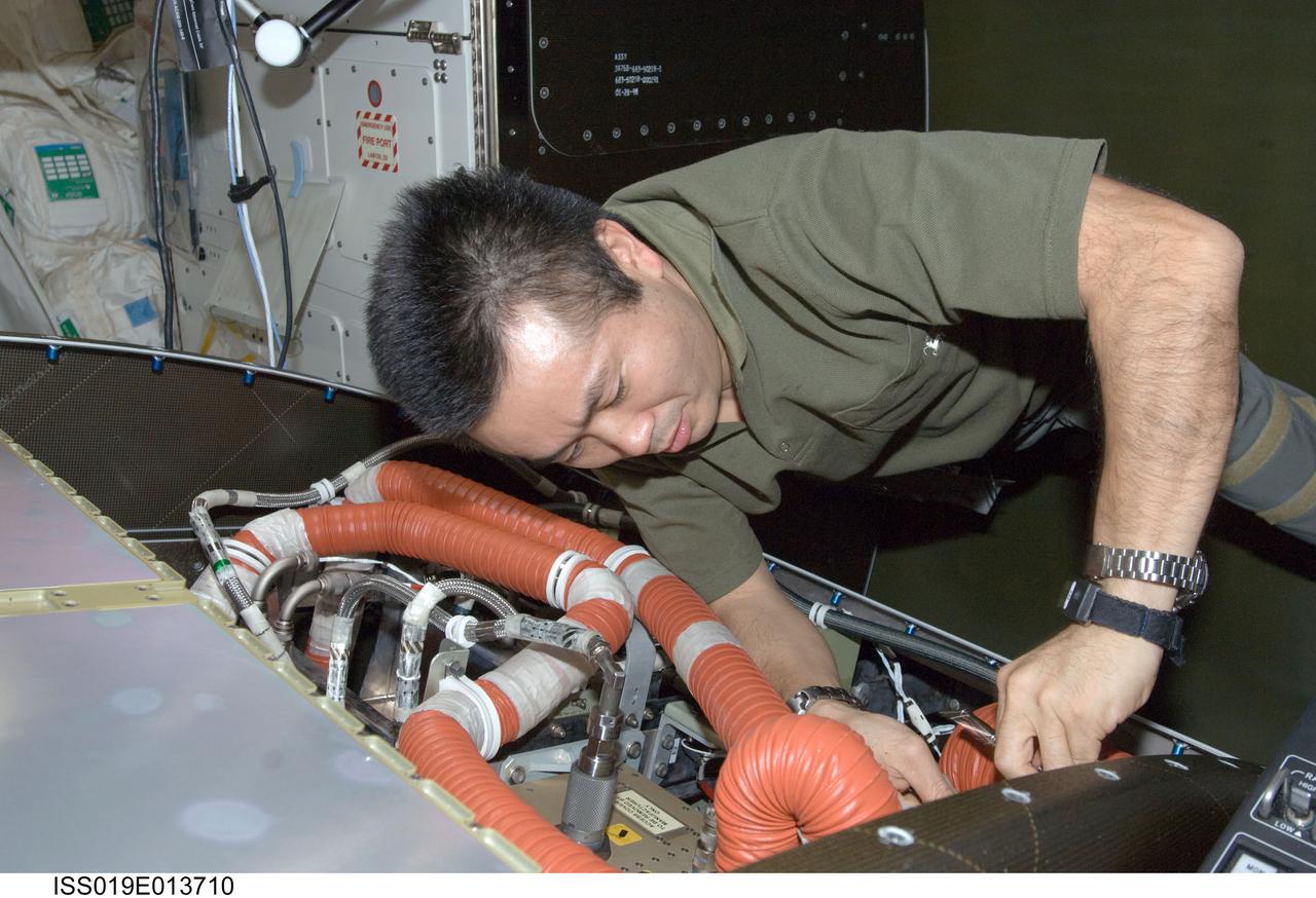
ISS019-E-013710 (5 May 2009) --- Japan Aerospace Exploration Agency (JAXA) astronaut Koichi Wakata, Expedition 19/20 flight engineer, cleans a fan filter on the Crew Health Care System Avionics Air Assembly (CHeCS AAA) in the Destiny laboratory of the International Space Station.
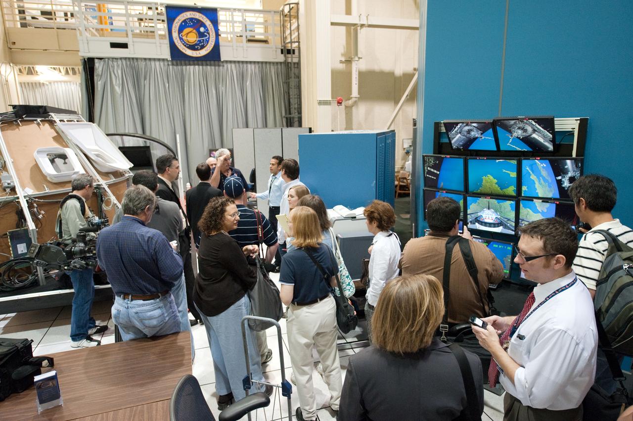
JSC2011-E-028125 (23 March 2011) --- News media representatives and NASA personnel are pictured during an STS-135 media day event in the Avionics Systems Laboratory at NASA's Johnson Space Center. Photo credit: NASA or National Aeronautics and Space Administration

JSC2011-E-028124 (23 March 2011) --- News media representatives and NASA personnel are pictured during an STS-135 media day event in the Avionics Systems Laboratory at NASA's Johnson Space Center. Photo credit: NASA or National Aeronautics and Space Administration
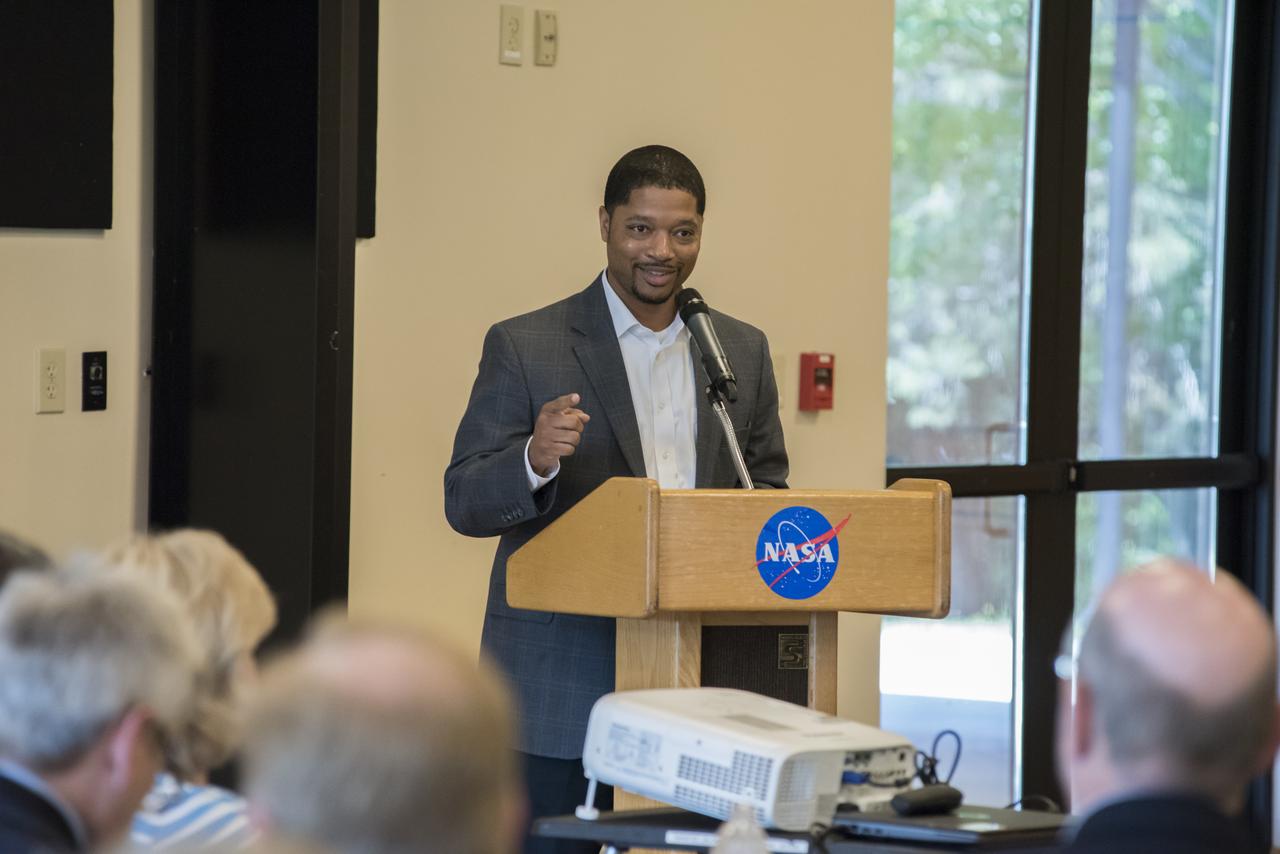
Markeeva Morgan, SLS avionics subsystem manager at NASA’s Marshall Space Flight Center, speaks to an audience of Marshall team members April 26 at the Overlook at Redstone. Morgan was the introductory speaker for the luncheon meeting of the Marshall Association, the center’s professional, employee service organization.
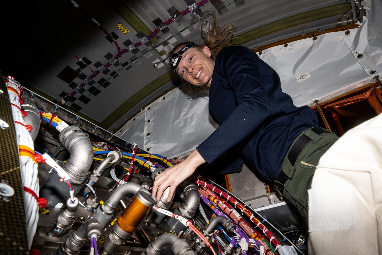
iss073e0379873 (July 21, 2025) --- NASA astronaut and Expedition 73 Flight Engineer Nichole Ayers works inside the International Space Station's Tranquility module swapping out a remote power controller module and inspecting components on the Avionics Rack.
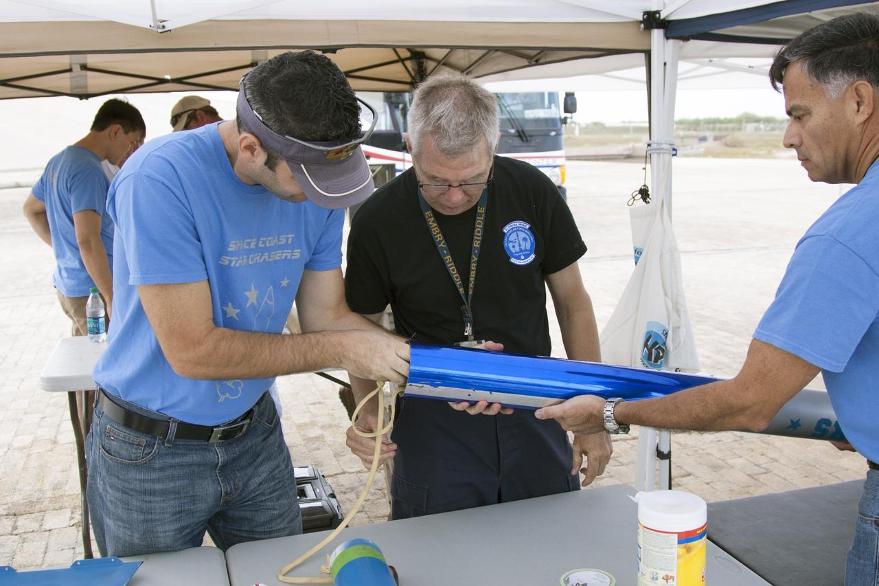
CAPE CANAVERAL, Fla. -- At NASA's Kennedy Space Center in Florida, from the left, Leandro James, rocket avionics lead, Gary Dahlke, high powered rocket subject matter expert, and Julio Najarro of Mechanical Systems make final adjustments to a small rocket prior to launch as part of Rocket University. The launch will test systems designed by the student engineers. As part of Rocket University, the engineers are given an opportunity to work a fast-track project to develop skills in developing spacecraft systems of the future. As NASA plans for future spaceflight programs to low-Earth orbit and beyond, teams of engineers at Kennedy are gaining experience in designing and flying launch vehicle systems on a small scale. Four teams of five to eight members from Kennedy are designing rockets complete with avionics and recovery systems. Launch operations require coordination with federal agencies, just as they would with rockets launched in support of a NASA mission. Photo credit: NASA/Jim Grossmann

VANDENBERG AIR FORCE BASE, Calif. -- At a Pegasus booster processing facility at Vandenberg Air Force Base in California, technicians install the avionic shelf on the Pegasus XL rocket. The avionics contained in this module will issue the guidance and flight control commands for the rocket. The Orbital Sciences Corp. Pegasus rocket will launch the Nuclear Spectroscopic Telescope Array (NuSTAR) into space. After the rocket and spacecraft are processed at Vandenberg, they will be flown on the Orbital Sciences’ L-1011 carrier aircraft to the Ronald Reagan Ballistic Missile Defense Test Site at the Pacific Ocean’s Kwajalein Atoll for launch. The high-energy x-ray telescope will conduct a census for black holes, map radioactive material in young supernovae remnants, and study the origins of cosmic rays and the extreme physics around collapsed stars. For more information, visit science.nasa.gov/missions/nustar/. Photo credit: NASA/Randy Beaudoin, VAFB
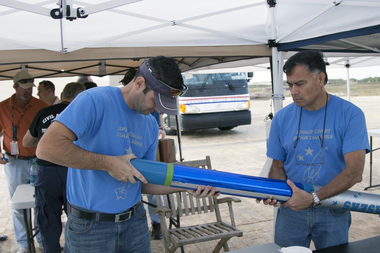
CAPE CANAVERAL, Fla. -- At NASA's Kennedy Space Center in Florida, from the left, Leandro James, rocket avionics lead, and Julio Najarro of Mechanical Systems make final adjustments to a small rocket prior to launch as part of Rocket University. The launch will test systems designed by the student engineers. As part of Rocket University, the engineers are given an opportunity to work a fast-track project to develop skills in developing spacecraft systems of the future. As NASA plans for future spaceflight programs to low-Earth orbit and beyond, teams of engineers at Kennedy are gaining experience in designing and flying launch vehicle systems on a small scale. Four teams of five to eight members from Kennedy are designing rockets complete with avionics and recovery systems. Launch operations require coordination with federal agencies, just as they would with rockets launched in support of a NASA mission. Photo credit: NASA/Jim Grossmann
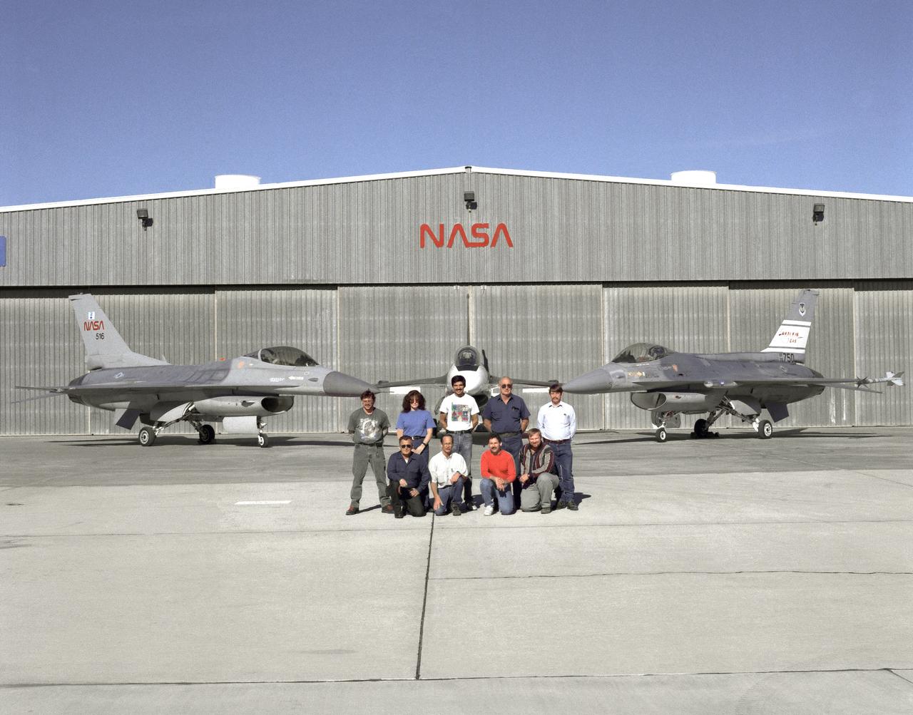
The support crew for the F-16A, the F-16XL no. 1, and the F-16 AFTI are, top row, left to right: Randy Weaver; mechanic, Susan Ligon; mechanic, Bob Garcia; Crew Chief, Rich Kelly; mechanic, Dale Edminister; Avionics Technician. Bottom row, left to right, Art Cope; mechanic, John Huffman; Avionics Technician, Jaime Garcia; Avionics Technician, Don Griffith, Avionics Tech. Co-op student. The F-16A (NASA 516), the only civil registered F-16 in existence, was transferred to Dryden from Langley, and was primarily used in engine tests and for parts. It was subsequently transfered from Dryden. The single-seat F-16XL no. 1 (NASA 849) was most recently used in the Cranked-Arrow Wing Aerodynamics Project (CAWAP) to test boundary layer pressures and distribution. Previously it had been used in a program to investigate the characteristics of sonic booms for NASA's High Speed Research Program. Data from the program will be used in the development of a high speed civilian transport. During the series of sonic boom research flights, the F-16XL was used to probe the shock waves being generated by a NASA SR-71 and record their shape and intensity. The Advanced Fighter Technology Integration (AFTI) F-16 was used to develop and demonstrate technologies to improve navigation and a pilot's ability to find and destroy enemy ground targets day or night, including adverse weather. Earlier research in the joint NASA-Air Force AFTI F-16 program demonstrated voice actuated controls, helmet-mounted sighting and integration of forward-mounted canards with the standard flight control system to achieve uncoupled flight.
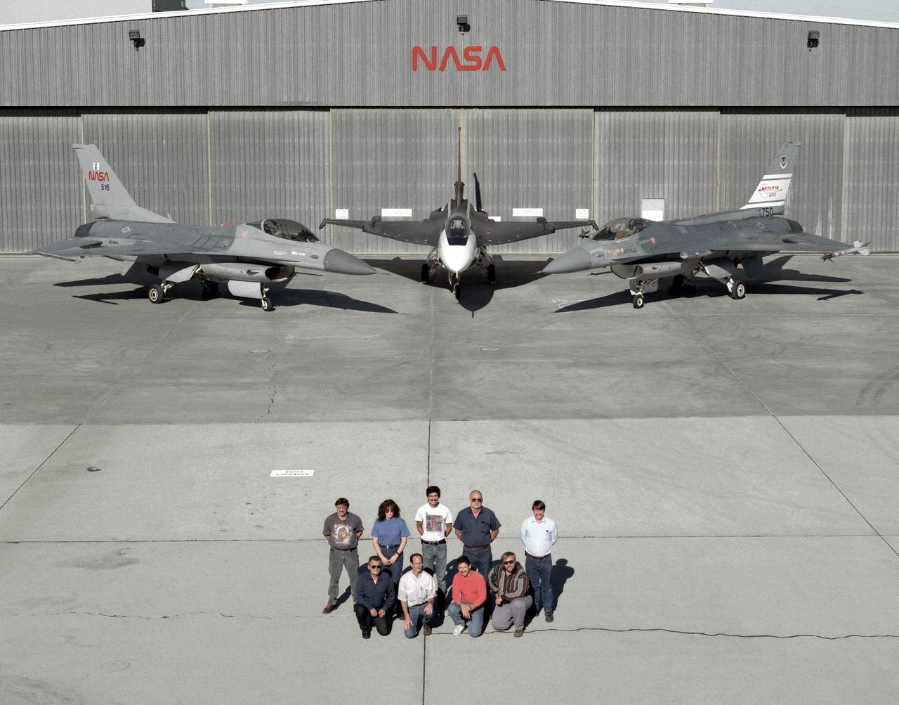
The support crew for the F-16A, the F-16XL no. 1, and the F-16 AFTI are, top row, left to right: Randy Weaver; mechanic, Susan Ligon; mechanic, Bob Garcia; Crew Chief, Rich Kelly; mechanic, Dale Edminister; Avionics Technician. Bottom row, left to right, Art Cope; mechanic, John Huffman; Avionics Technician, Jaime Garcia; Avionics Technician, Don Griffith, Avionics Tech. Co-op student. The F-16A (NASA 516), the only civil registered F-16 in existence, was transferred to Dryden from Langley, and was primarily used in engine tests and for parts. It was subsequently transfered from Dryden. The single-seat F-16XL no. 1 (NASA 849) was most recently used in the Cranked-Arrow Wing Aerodynamics Project (CAWAP) to test boundary layer pressures and distribution. Previously it had been used in a program to investigate the characteristics of sonic booms for NASA's High Speed Research Program. Data from the program will be used in the development of a high speed civilian transport. During the series of sonic boom research flights, the F-16XL was used to probe the shock waves being generated by a NASA SR-71 and record their shape and intensity. The Advanced Fighter Technology Integration (AFTI) F-16 was used to develop and demonstrate technologies to improve navigation and a pilot's ability to find and destroy enemy ground targets day or night, including adverse weather. Earlier research in the joint NASA-Air Force AFTI F-16 program demonstrated voice actuated controls, helmet-mounted sighting and integration of forward-mounted canards with the standard flight control system to achieve uncoupled flight.
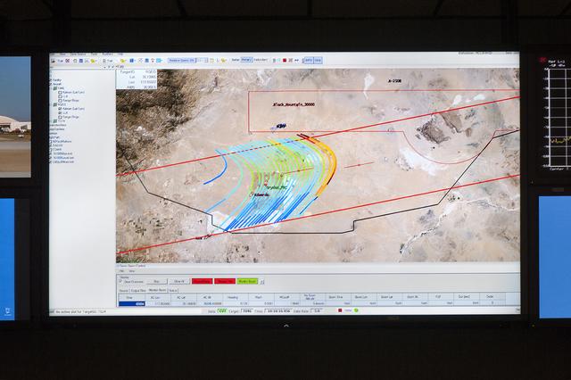
The CISBoomDA display allows the pilot of a supersonic aircraft to monitor the locations of any sonic booms produced, to prevent the aircraft from positioning booms in restricted area.
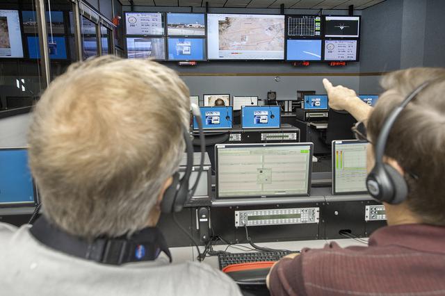
Engineers and researchers at NASA’s Armstrong Flight Research Center monitored the flights, and were able to observe the mapping of the sonic boom carpet from the F-18, from the center’s Mission Control Center.
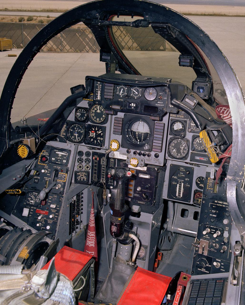
View of the cockpit of NASA's F-14, tail number 991. This aircraft was the first of a series of post-Vietnam fighters, followed by the F-15, F-16, and F-18. They were designed for maneuverability in air-to-air combat. The F-14s had a spin problem that posed problems for its ability to engage successfully in a dogfight, since it tended to depart from controlled flight at the high angles of attack that frequently occur in close-in engagements.
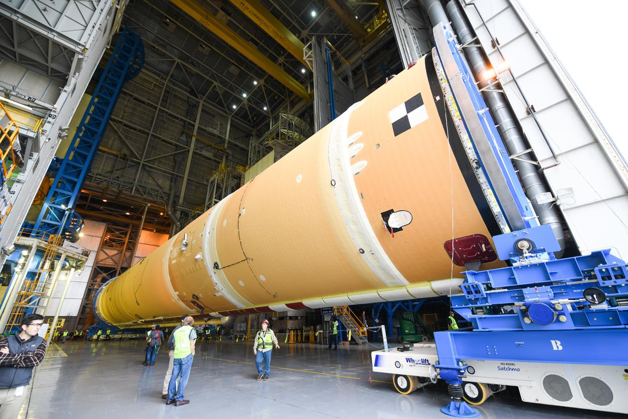
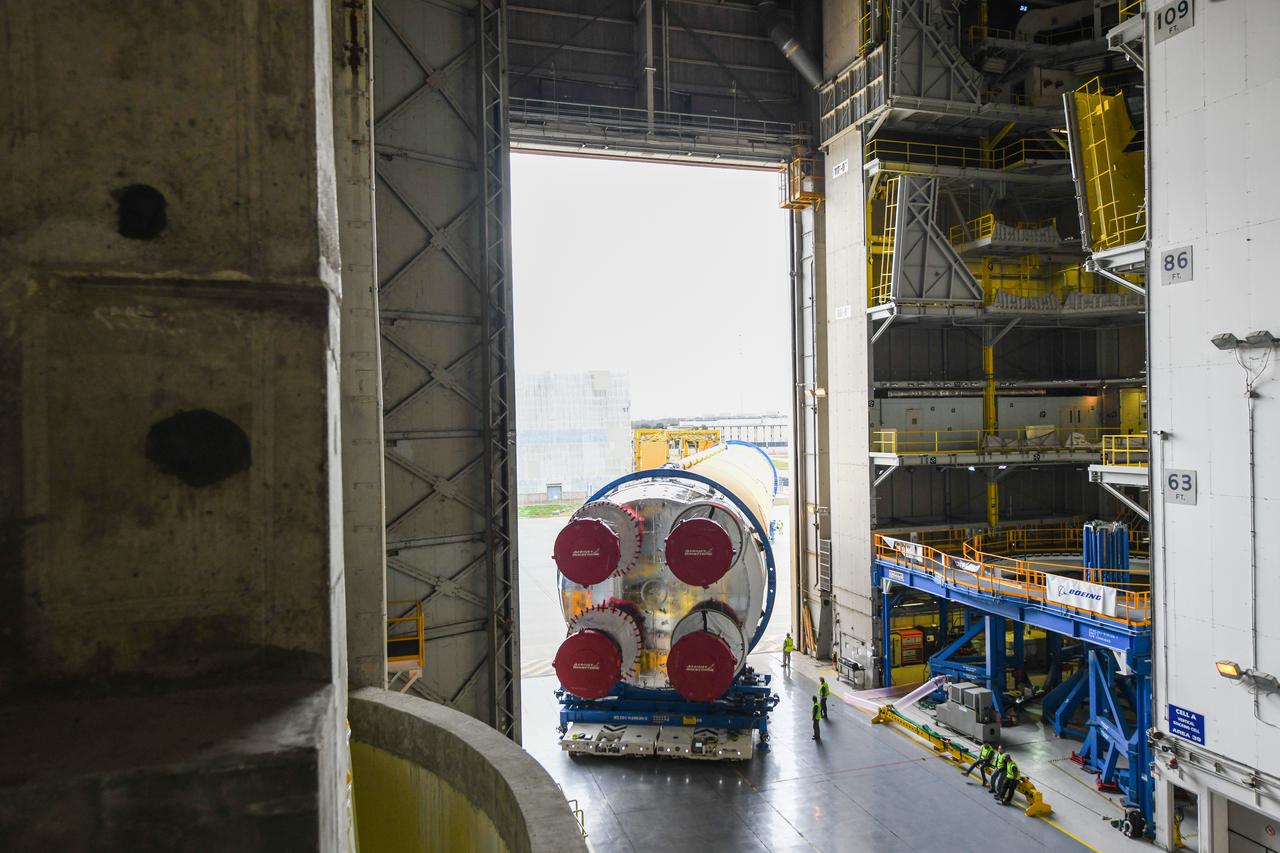
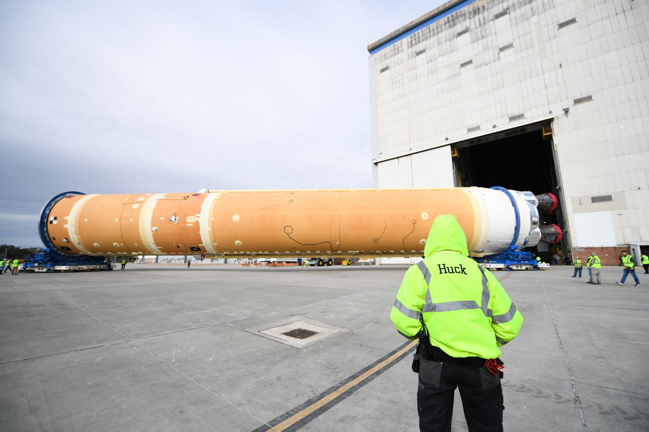
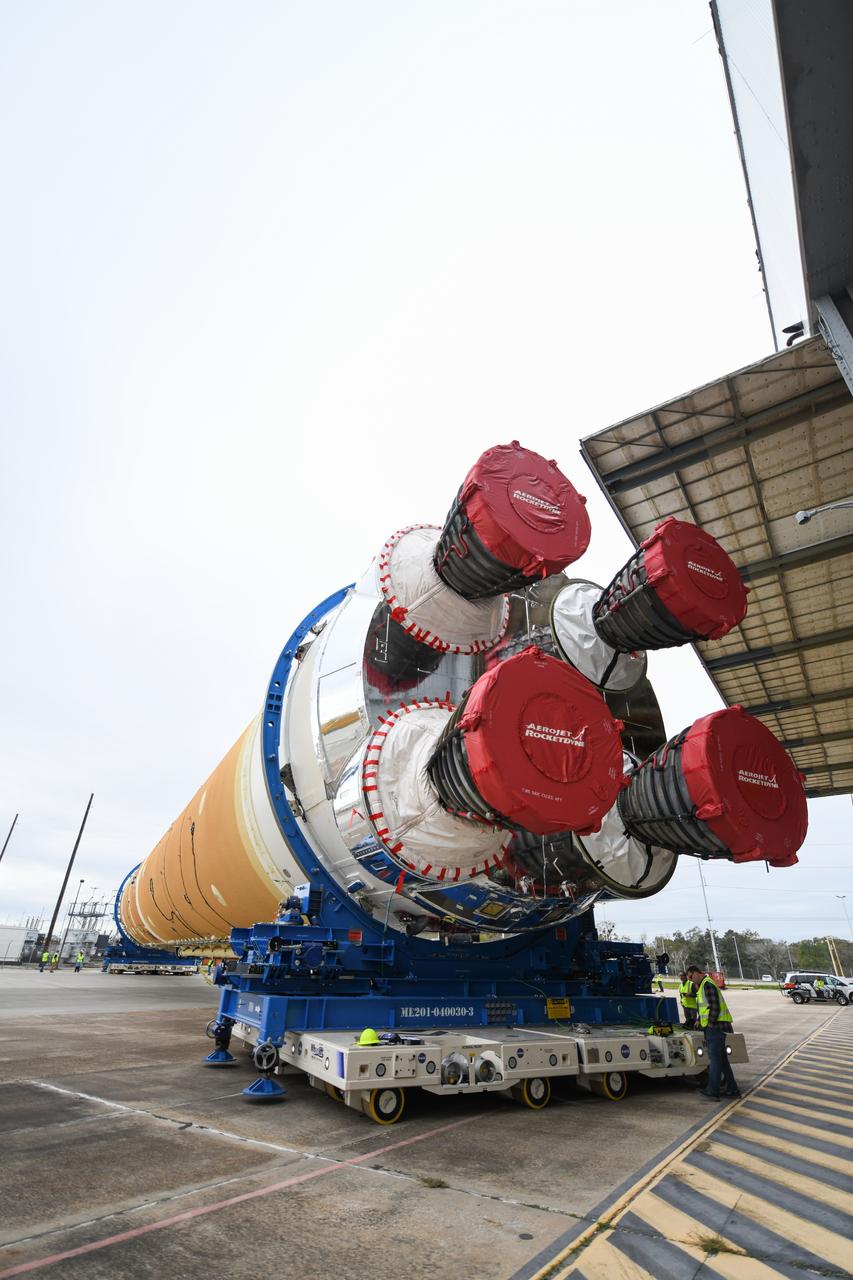
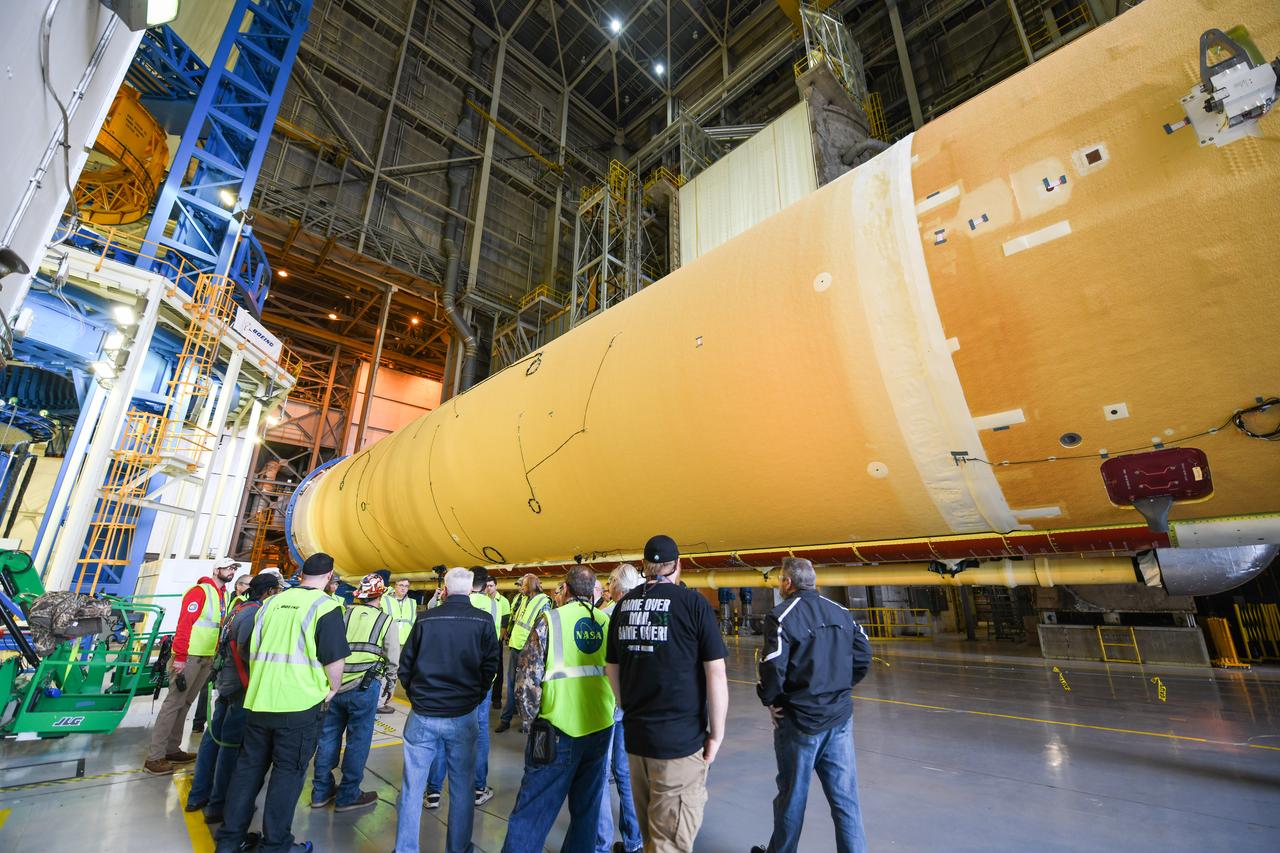
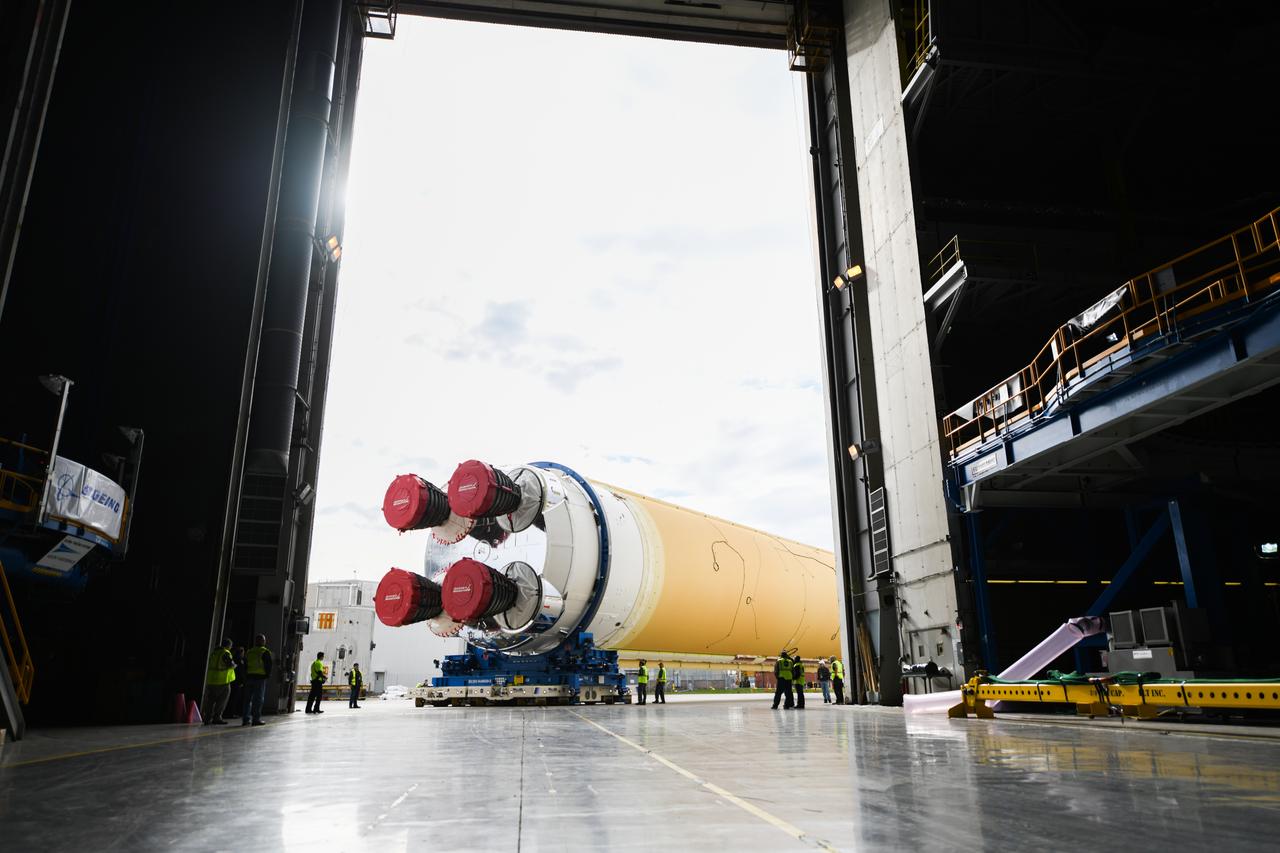
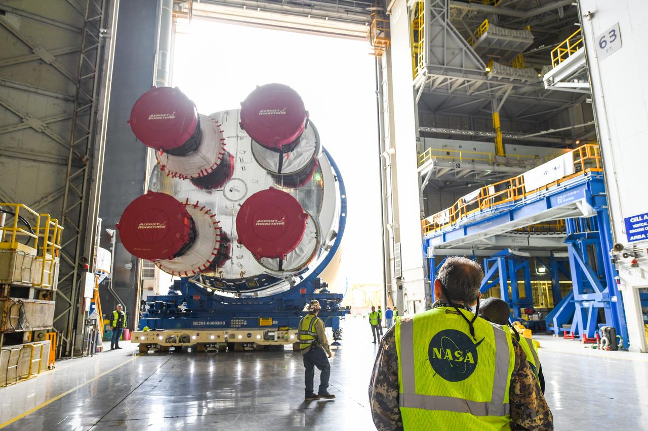
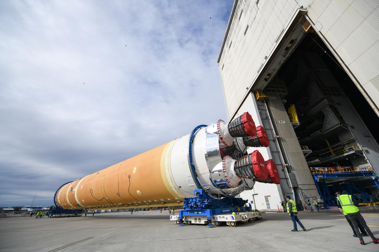
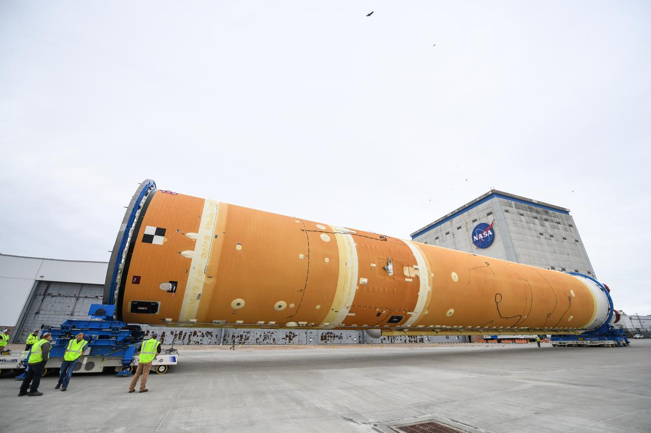
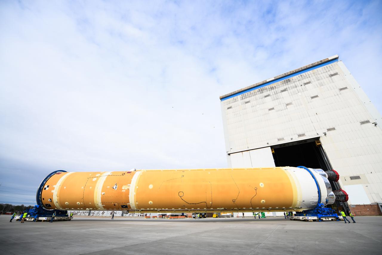
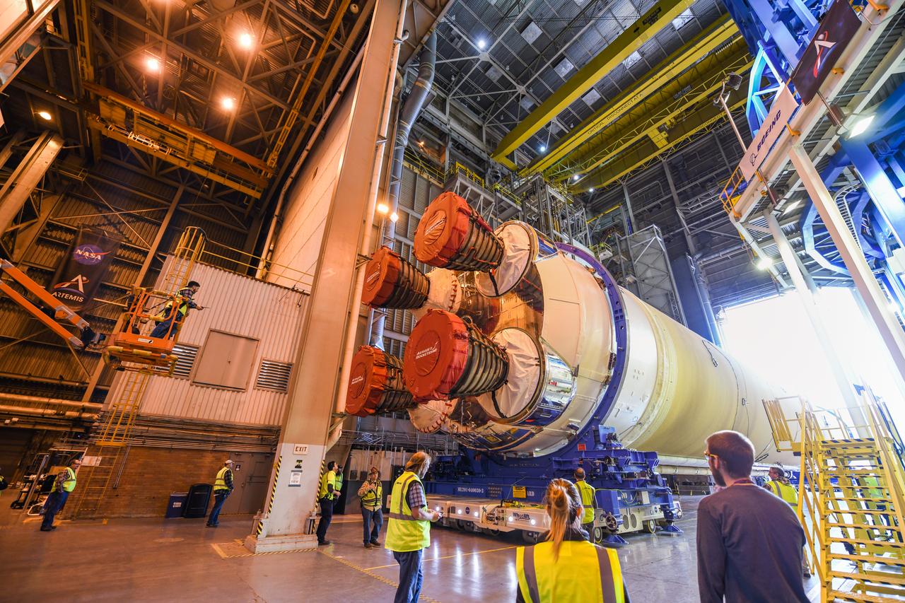
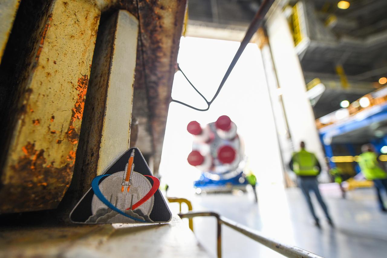
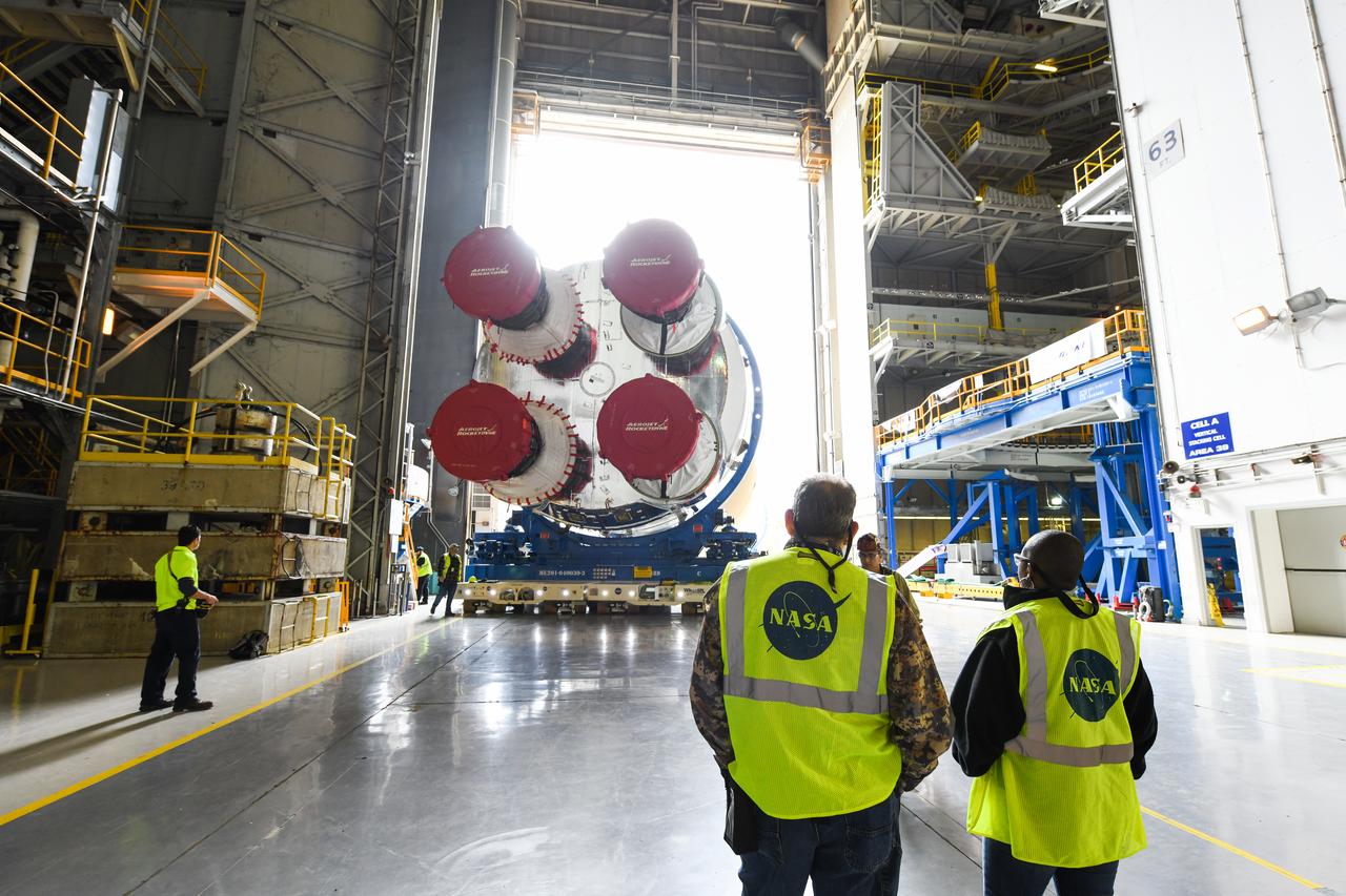
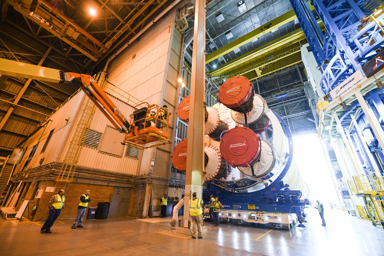
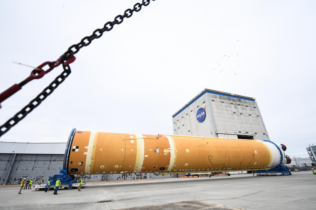
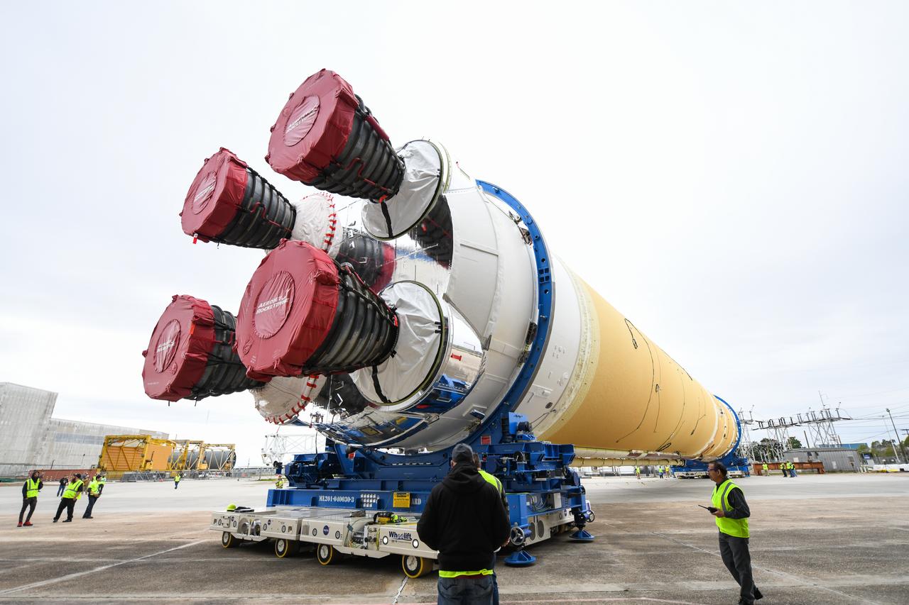
These images show how teams at NASA’s Michoud Assembly Facility in New Orleans moved the core stage, complete with all four RS-25 engines, for NASA’s Space Launch System (SLS) rocket to Building 110 for final shipping preparations on Jan. 1. The SLS core stage includes state-of-the-art avionics, propulsion systems and two colossal propellant tanks that collectively hold 733,000 gallons of liquid oxygen and liquid hydrogen to power its four RS-25 engines. The completed stage, which will provide more than 2 million pounds of thrust to help power the first Artemis mission to the Moon, will be shipped via the agency’s Pegasus barge from Michoud to NASA’s Stennis Space Center near Bay St. Louis, Mississippi, later this month. Once at Stennis, the Artemis rocket stage will be loaded into the B-2 Test Stand for the core stage Green Run test series. The comprehensive test campaign will progressively bring the entire core stage, including its avionics and engines, to life for the first time to verify the stage is fit for flight ahead of the launch of Artemis I.
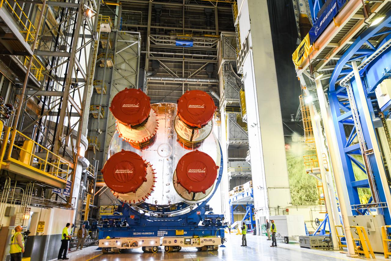
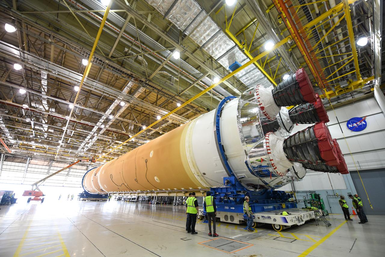
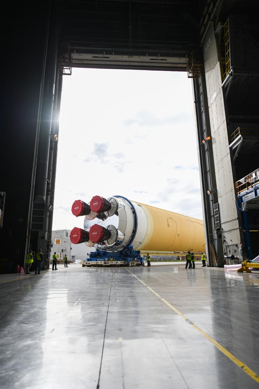
These images show how teams at NASA’s Michoud Assembly Facility in New Orleans moved the core stage, complete with all four RS-25 engines, for NASA’s Space Launch System (SLS) rocket to Building 110 for final shipping preparations on Jan. 1. The SLS core stage includes state-of-the-art avionics, propulsion systems and two colossal propellant tanks that collectively hold 733,000 gallons of liquid oxygen and liquid hydrogen to power its four RS-25 engines. The completed stage, which will provide more than 2 million pounds of thrust to help power the first Artemis mission to the Moon, will be shipped via the agency’s Pegasus barge from Michoud to NASA’s Stennis Space Center near Bay St. Louis, Mississippi, later this month. Once at Stennis, the Artemis rocket stage will be loaded into the B-2 Test Stand for the core stage Green Run test series. The comprehensive test campaign will progressively bring the entire core stage, including its avionics and engines, to life for the first time to verify the stage is fit for flight ahead of the launch of Artemis I.
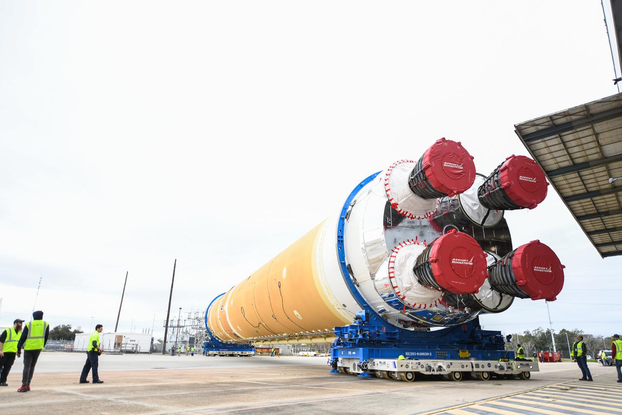
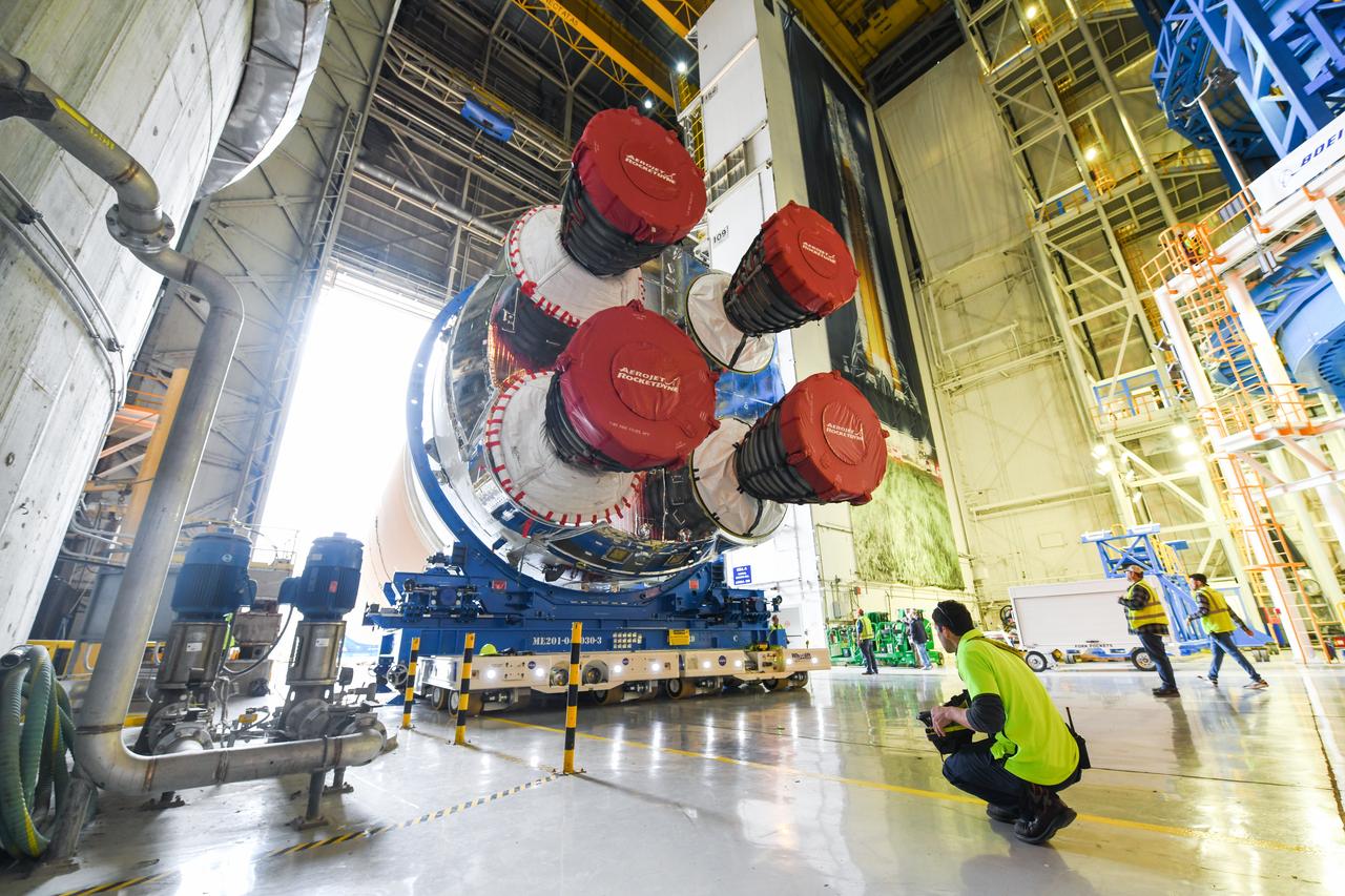
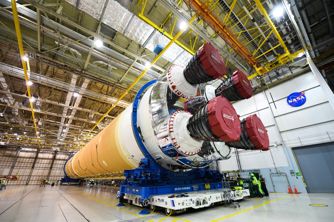
These images show how teams at NASA’s Michoud Assembly Facility in New Orleans moved the core stage, complete with all four RS-25 engines, for NASA’s Space Launch System (SLS) rocket to Building 110 for final shipping preparations on Jan. 1. The SLS core stage includes state-of-the-art avionics, propulsion systems and two colossal propellant tanks that collectively hold 733,000 gallons of liquid oxygen and liquid hydrogen to power its four RS-25 engines. The completed stage, which will provide more than 2 million pounds of thrust to help power the first Artemis mission to the Moon, will be shipped via the agency’s Pegasus barge from Michoud to NASA’s Stennis Space Center near Bay St. Louis, Mississippi, later this month. Once at Stennis, the Artemis rocket stage will be loaded into the B-2 Test Stand for the core stage Green Run test series. The comprehensive test campaign will progressively bring the entire core stage, including its avionics and engines, to life for the first time to verify the stage is fit for flight ahead of the launch of Artemis I.
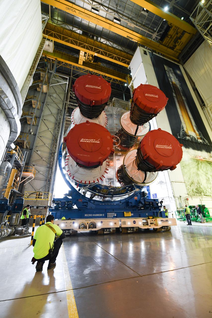
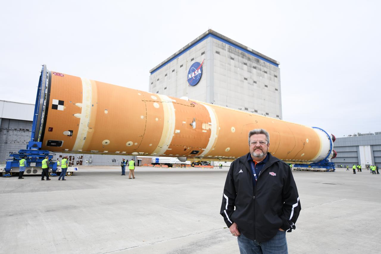
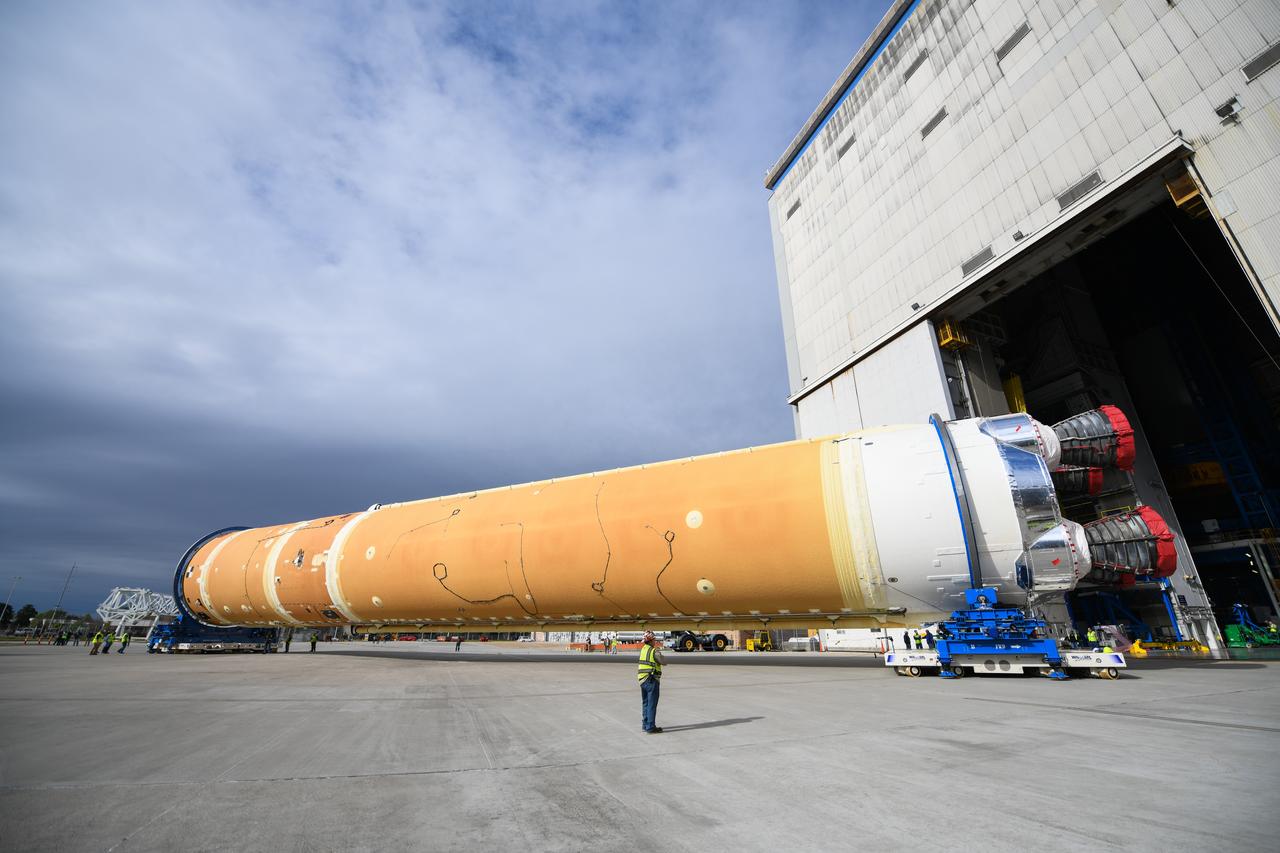
These images show how teams at NASA’s Michoud Assembly Facility in New Orleans moved the core stage, complete with all four RS-25 engines, for NASA’s Space Launch System (SLS) rocket to Building 110 for final shipping preparations on Jan. 1. The SLS core stage includes state-of-the-art avionics, propulsion systems and two colossal propellant tanks that collectively hold 733,000 gallons of liquid oxygen and liquid hydrogen to power its four RS-25 engines. The completed stage, which will provide more than 2 million pounds of thrust to help power the first Artemis mission to the Moon, will be shipped via the agency’s Pegasus barge from Michoud to NASA’s Stennis Space Center near Bay St. Louis, Mississippi, later this month. Once at Stennis, the Artemis rocket stage will be loaded into the B-2 Test Stand for the core stage Green Run test series. The comprehensive test campaign will progressively bring the entire core stage, including its avionics and engines, to life for the first time to verify the stage is fit for flight ahead of the launch of Artemis I.
These images show how teams at NASA’s Michoud Assembly Facility in New Orleans moved the core stage, complete with all four RS-25 engines, for NASA’s Space Launch System (SLS) rocket to Building 110 for final shipping preparations on Jan. 1. The SLS core stage includes state-of-the-art avionics, propulsion systems and two colossal propellant tanks that collectively hold 733,000 gallons of liquid oxygen and liquid hydrogen to power its four RS-25 engines. The completed stage, which will provide more than 2 million pounds of thrust to help power the first Artemis mission to the Moon, will be shipped via the agency’s Pegasus barge from Michoud to NASA’s Stennis Space Center near Bay St. Louis, Mississippi, later this month. Once at Stennis, the Artemis rocket stage will be loaded into the B-2 Test Stand for the core stage Green Run test series. The comprehensive test campaign will progressively bring the entire core stage, including its avionics and engines, to life for the first time to verify the stage is fit for flight ahead of the launch of Artemis I.
These images show how teams at NASA’s Michoud Assembly Facility in New Orleans moved the core stage, complete with all four RS-25 engines, for NASA’s Space Launch System (SLS) rocket to Building 110 for final shipping preparations on Jan. 1. The SLS core stage includes state-of-the-art avionics, propulsion systems and two colossal propellant tanks that collectively hold 733,000 gallons of liquid oxygen and liquid hydrogen to power its four RS-25 engines. The completed stage, which will provide more than 2 million pounds of thrust to help power the first Artemis mission to the Moon, will be shipped via the agency’s Pegasus barge from Michoud to NASA’s Stennis Space Center near Bay St. Louis, Mississippi, later this month. Once at Stennis, the Artemis rocket stage will be loaded into the B-2 Test Stand for the core stage Green Run test series. The comprehensive test campaign will progressively bring the entire core stage, including its avionics and engines, to life for the first time to verify the stage is fit for flight ahead of the launch of Artemis I.
These images show how teams at NASA’s Michoud Assembly Facility in New Orleans moved the core stage, complete with all four RS-25 engines, for NASA’s Space Launch System (SLS) rocket to Building 110 for final shipping preparations on Jan. 1. The SLS core stage includes state-of-the-art avionics, propulsion systems and two colossal propellant tanks that collectively hold 733,000 gallons of liquid oxygen and liquid hydrogen to power its four RS-25 engines. The completed stage, which will provide more than 2 million pounds of thrust to help power the first Artemis mission to the Moon, will be shipped via the agency’s Pegasus barge from Michoud to NASA’s Stennis Space Center near Bay St. Louis, Mississippi, later this month. Once at Stennis, the Artemis rocket stage will be loaded into the B-2 Test Stand for the core stage Green Run test series. The comprehensive test campaign will progressively bring the entire core stage, including its avionics and engines, to life for the first time to verify the stage is fit for flight ahead of the launch of Artemis I.
These images show how teams at NASA’s Michoud Assembly Facility in New Orleans moved the core stage, complete with all four RS-25 engines, for NASA’s Space Launch System (SLS) rocket to Building 110 for final shipping preparations on Jan. 1. The SLS core stage includes state-of-the-art avionics, propulsion systems and two colossal propellant tanks that collectively hold 733,000 gallons of liquid oxygen and liquid hydrogen to power its four RS-25 engines. The completed stage, which will provide more than 2 million pounds of thrust to help power the first Artemis mission to the Moon, will be shipped via the agency’s Pegasus barge from Michoud to NASA’s Stennis Space Center near Bay St. Louis, Mississippi, later this month. Once at Stennis, the Artemis rocket stage will be loaded into the B-2 Test Stand for the core stage Green Run test series. The comprehensive test campaign will progressively bring the entire core stage, including its avionics and engines, to life for the first time to verify the stage is fit for flight ahead of the launch of Artemis I.
These images show how teams at NASA’s Michoud Assembly Facility in New Orleans moved the core stage, complete with all four RS-25 engines, for NASA’s Space Launch System (SLS) rocket to Building 110 for final shipping preparations on Jan. 1. The SLS core stage includes state-of-the-art avionics, propulsion systems and two colossal propellant tanks that collectively hold 733,000 gallons of liquid oxygen and liquid hydrogen to power its four RS-25 engines. The completed stage, which will provide more than 2 million pounds of thrust to help power the first Artemis mission to the Moon, will be shipped via the agency’s Pegasus barge from Michoud to NASA’s Stennis Space Center near Bay St. Louis, Mississippi, later this month. Once at Stennis, the Artemis rocket stage will be loaded into the B-2 Test Stand for the core stage Green Run test series. The comprehensive test campaign will progressively bring the entire core stage, including its avionics and engines, to life for the first time to verify the stage is fit for flight ahead of the launch of Artemis I.
These images show how teams at NASA’s Michoud Assembly Facility in New Orleans moved the core stage, complete with all four RS-25 engines, for NASA’s Space Launch System (SLS) rocket to Building 110 for final shipping preparations on Jan. 1. The SLS core stage includes state-of-the-art avionics, propulsion systems and two colossal propellant tanks that collectively hold 733,000 gallons of liquid oxygen and liquid hydrogen to power its four RS-25 engines. The completed stage, which will provide more than 2 million pounds of thrust to help power the first Artemis mission to the Moon, will be shipped via the agency’s Pegasus barge from Michoud to NASA’s Stennis Space Center near Bay St. Louis, Mississippi, later this month. Once at Stennis, the Artemis rocket stage will be loaded into the B-2 Test Stand for the core stage Green Run test series. The comprehensive test campaign will progressively bring the entire core stage, including its avionics and engines, to life for the first time to verify the stage is fit for flight ahead of the launch of Artemis I.
These images show how teams at NASA’s Michoud Assembly Facility in New Orleans moved the core stage, complete with all four RS-25 engines, for NASA’s Space Launch System (SLS) rocket to Building 110 for final shipping preparations on Jan. 1. The SLS core stage includes state-of-the-art avionics, propulsion systems and two colossal propellant tanks that collectively hold 733,000 gallons of liquid oxygen and liquid hydrogen to power its four RS-25 engines. The completed stage, which will provide more than 2 million pounds of thrust to help power the first Artemis mission to the Moon, will be shipped via the agency’s Pegasus barge from Michoud to NASA’s Stennis Space Center near Bay St. Louis, Mississippi, later this month. Once at Stennis, the Artemis rocket stage will be loaded into the B-2 Test Stand for the core stage Green Run test series. The comprehensive test campaign will progressively bring the entire core stage, including its avionics and engines, to life for the first time to verify the stage is fit for flight ahead of the launch of Artemis I.
These images show how teams at NASA’s Michoud Assembly Facility in New Orleans moved the core stage, complete with all four RS-25 engines, for NASA’s Space Launch System (SLS) rocket to Building 110 for final shipping preparations on Jan. 1. The SLS core stage includes state-of-the-art avionics, propulsion systems and two colossal propellant tanks that collectively hold 733,000 gallons of liquid oxygen and liquid hydrogen to power its four RS-25 engines. The completed stage, which will provide more than 2 million pounds of thrust to help power the first Artemis mission to the Moon, will be shipped via the agency’s Pegasus barge from Michoud to NASA’s Stennis Space Center near Bay St. Louis, Mississippi, later this month. Once at Stennis, the Artemis rocket stage will be loaded into the B-2 Test Stand for the core stage Green Run test series. The comprehensive test campaign will progressively bring the entire core stage, including its avionics and engines, to life for the first time to verify the stage is fit for flight ahead of the launch of Artemis I.
These images show how teams at NASA’s Michoud Assembly Facility in New Orleans moved the core stage, complete with all four RS-25 engines, for NASA’s Space Launch System (SLS) rocket to Building 110 for final shipping preparations on Jan. 1. The SLS core stage includes state-of-the-art avionics, propulsion systems and two colossal propellant tanks that collectively hold 733,000 gallons of liquid oxygen and liquid hydrogen to power its four RS-25 engines. The completed stage, which will provide more than 2 million pounds of thrust to help power the first Artemis mission to the Moon, will be shipped via the agency’s Pegasus barge from Michoud to NASA’s Stennis Space Center near Bay St. Louis, Mississippi, later this month. Once at Stennis, the Artemis rocket stage will be loaded into the B-2 Test Stand for the core stage Green Run test series. The comprehensive test campaign will progressively bring the entire core stage, including its avionics and engines, to life for the first time to verify the stage is fit for flight ahead of the launch of Artemis I.
These images show how teams at NASA’s Michoud Assembly Facility in New Orleans moved the core stage, complete with all four RS-25 engines, for NASA’s Space Launch System (SLS) rocket to Building 110 for final shipping preparations on Jan. 1. The SLS core stage includes state-of-the-art avionics, propulsion systems and two colossal propellant tanks that collectively hold 733,000 gallons of liquid oxygen and liquid hydrogen to power its four RS-25 engines. The completed stage, which will provide more than 2 million pounds of thrust to help power the first Artemis mission to the Moon, will be shipped via the agency’s Pegasus barge from Michoud to NASA’s Stennis Space Center near Bay St. Louis, Mississippi, later this month. Once at Stennis, the Artemis rocket stage will be loaded into the B-2 Test Stand for the core stage Green Run test series. The comprehensive test campaign will progressively bring the entire core stage, including its avionics and engines, to life for the first time to verify the stage is fit for flight ahead of the launch of Artemis I.

These images show how teams at NASA’s Michoud Assembly Facility in New Orleans moved the core stage, complete with all four RS-25 engines, for NASA’s Space Launch System (SLS) rocket to Building 110 for final shipping preparations on Jan. 1. The SLS core stage includes state-of-the-art avionics, propulsion systems and two colossal propellant tanks that collectively hold 733,000 gallons of liquid oxygen and liquid hydrogen to power its four RS-25 engines. The completed stage, which will provide more than 2 million pounds of thrust to help power the first Artemis mission to the Moon, will be shipped via the agency’s Pegasus barge from Michoud to NASA’s Stennis Space Center near Bay St. Louis, Mississippi, later this month. Once at Stennis, the Artemis rocket stage will be loaded into the B-2 Test Stand for the core stage Green Run test series. The comprehensive test campaign will progressively bring the entire core stage, including its avionics and engines, to life for the first time to verify the stage is fit for flight ahead of the launch of Artemis I.
These images show how teams at NASA’s Michoud Assembly Facility in New Orleans moved the core stage, complete with all four RS-25 engines, for NASA’s Space Launch System (SLS) rocket to Building 110 for final shipping preparations on Jan. 1. The SLS core stage includes state-of-the-art avionics, propulsion systems and two colossal propellant tanks that collectively hold 733,000 gallons of liquid oxygen and liquid hydrogen to power its four RS-25 engines. The completed stage, which will provide more than 2 million pounds of thrust to help power the first Artemis mission to the Moon, will be shipped via the agency’s Pegasus barge from Michoud to NASA’s Stennis Space Center near Bay St. Louis, Mississippi, later this month. Once at Stennis, the Artemis rocket stage will be loaded into the B-2 Test Stand for the core stage Green Run test series. The comprehensive test campaign will progressively bring the entire core stage, including its avionics and engines, to life for the first time to verify the stage is fit for flight ahead of the launch of Artemis I.
These images show how teams at NASA’s Michoud Assembly Facility in New Orleans moved the core stage, complete with all four RS-25 engines, for NASA’s Space Launch System (SLS) rocket to Building 110 for final shipping preparations on Jan. 1. The SLS core stage includes state-of-the-art avionics, propulsion systems and two colossal propellant tanks that collectively hold 733,000 gallons of liquid oxygen and liquid hydrogen to power its four RS-25 engines. The completed stage, which will provide more than 2 million pounds of thrust to help power the first Artemis mission to the Moon, will be shipped via the agency’s Pegasus barge from Michoud to NASA’s Stennis Space Center near Bay St. Louis, Mississippi, later this month. Once at Stennis, the Artemis rocket stage will be loaded into the B-2 Test Stand for the core stage Green Run test series. The comprehensive test campaign will progressively bring the entire core stage, including its avionics and engines, to life for the first time to verify the stage is fit for flight ahead of the launch of Artemis I.
These images show how teams at NASA’s Michoud Assembly Facility in New Orleans moved the core stage, complete with all four RS-25 engines, for NASA’s Space Launch System (SLS) rocket to Building 110 for final shipping preparations on Jan. 1. The SLS core stage includes state-of-the-art avionics, propulsion systems and two colossal propellant tanks that collectively hold 733,000 gallons of liquid oxygen and liquid hydrogen to power its four RS-25 engines. The completed stage, which will provide more than 2 million pounds of thrust to help power the first Artemis mission to the Moon, will be shipped via the agency’s Pegasus barge from Michoud to NASA’s Stennis Space Center near Bay St. Louis, Mississippi, later this month. Once at Stennis, the Artemis rocket stage will be loaded into the B-2 Test Stand for the core stage Green Run test series. The comprehensive test campaign will progressively bring the entire core stage, including its avionics and engines, to life for the first time to verify the stage is fit for flight ahead of the launch of Artemis I.
These images show how teams at NASA’s Michoud Assembly Facility in New Orleans moved the core stage, complete with all four RS-25 engines, for NASA’s Space Launch System (SLS) rocket to Building 110 for final shipping preparations on Jan. 1. The SLS core stage includes state-of-the-art avionics, propulsion systems and two colossal propellant tanks that collectively hold 733,000 gallons of liquid oxygen and liquid hydrogen to power its four RS-25 engines. The completed stage, which will provide more than 2 million pounds of thrust to help power the first Artemis mission to the Moon, will be shipped via the agency’s Pegasus barge from Michoud to NASA’s Stennis Space Center near Bay St. Louis, Mississippi, later this month. Once at Stennis, the Artemis rocket stage will be loaded into the B-2 Test Stand for the core stage Green Run test series. The comprehensive test campaign will progressively bring the entire core stage, including its avionics and engines, to life for the first time to verify the stage is fit for flight ahead of the launch of Artemis I.
These images show how teams at NASA’s Michoud Assembly Facility in New Orleans moved the core stage, complete with all four RS-25 engines, for NASA’s Space Launch System (SLS) rocket to Building 110 for final shipping preparations on Jan. 1. The SLS core stage includes state-of-the-art avionics, propulsion systems and two colossal propellant tanks that collectively hold 733,000 gallons of liquid oxygen and liquid hydrogen to power its four RS-25 engines. The completed stage, which will provide more than 2 million pounds of thrust to help power the first Artemis mission to the Moon, will be shipped via the agency’s Pegasus barge from Michoud to NASA’s Stennis Space Center near Bay St. Louis, Mississippi, later this month. Once at Stennis, the Artemis rocket stage will be loaded into the B-2 Test Stand for the core stage Green Run test series. The comprehensive test campaign will progressively bring the entire core stage, including its avionics and engines, to life for the first time to verify the stage is fit for flight ahead of the launch of Artemis I.
These images show how teams at NASA’s Michoud Assembly Facility in New Orleans moved the core stage, complete with all four RS-25 engines, for NASA’s Space Launch System (SLS) rocket to Building 110 for final shipping preparations on Jan. 1. The SLS core stage includes state-of-the-art avionics, propulsion systems and two colossal propellant tanks that collectively hold 733,000 gallons of liquid oxygen and liquid hydrogen to power its four RS-25 engines. The completed stage, which will provide more than 2 million pounds of thrust to help power the first Artemis mission to the Moon, will be shipped via the agency’s Pegasus barge from Michoud to NASA’s Stennis Space Center near Bay St. Louis, Mississippi, later this month. Once at Stennis, the Artemis rocket stage will be loaded into the B-2 Test Stand for the core stage Green Run test series. The comprehensive test campaign will progressively bring the entire core stage, including its avionics and engines, to life for the first time to verify the stage is fit for flight ahead of the launch of Artemis I.
These images show how teams at NASA’s Michoud Assembly Facility in New Orleans moved the core stage, complete with all four RS-25 engines, for NASA’s Space Launch System (SLS) rocket to Building 110 for final shipping preparations on Jan. 1. The SLS core stage includes state-of-the-art avionics, propulsion systems and two colossal propellant tanks that collectively hold 733,000 gallons of liquid oxygen and liquid hydrogen to power its four RS-25 engines. The completed stage, which will provide more than 2 million pounds of thrust to help power the first Artemis mission to the Moon, will be shipped via the agency’s Pegasus barge from Michoud to NASA’s Stennis Space Center near Bay St. Louis, Mississippi, later this month. Once at Stennis, the Artemis rocket stage will be loaded into the B-2 Test Stand for the core stage Green Run test series. The comprehensive test campaign will progressively bring the entire core stage, including its avionics and engines, to life for the first time to verify the stage is fit for flight ahead of the launch of Artemis I.
These images show how teams at NASA’s Michoud Assembly Facility in New Orleans moved the core stage, complete with all four RS-25 engines, for NASA’s Space Launch System (SLS) rocket to Building 110 for final shipping preparations on Jan. 1. The SLS core stage includes state-of-the-art avionics, propulsion systems and two colossal propellant tanks that collectively hold 733,000 gallons of liquid oxygen and liquid hydrogen to power its four RS-25 engines. The completed stage, which will provide more than 2 million pounds of thrust to help power the first Artemis mission to the Moon, will be shipped via the agency’s Pegasus barge from Michoud to NASA’s Stennis Space Center near Bay St. Louis, Mississippi, later this month. Once at Stennis, the Artemis rocket stage will be loaded into the B-2 Test Stand for the core stage Green Run test series. The comprehensive test campaign will progressively bring the entire core stage, including its avionics and engines, to life for the first time to verify the stage is fit for flight ahead of the launch of Artemis I.
These images show how teams at NASA’s Michoud Assembly Facility in New Orleans moved the core stage, complete with all four RS-25 engines, for NASA’s Space Launch System (SLS) rocket to Building 110 for final shipping preparations on Jan. 1. The SLS core stage includes state-of-the-art avionics, propulsion systems and two colossal propellant tanks that collectively hold 733,000 gallons of liquid oxygen and liquid hydrogen to power its four RS-25 engines. The completed stage, which will provide more than 2 million pounds of thrust to help power the first Artemis mission to the Moon, will be shipped via the agency’s Pegasus barge from Michoud to NASA’s Stennis Space Center near Bay St. Louis, Mississippi, later this month. Once at Stennis, the Artemis rocket stage will be loaded into the B-2 Test Stand for the core stage Green Run test series. The comprehensive test campaign will progressively bring the entire core stage, including its avionics and engines, to life for the first time to verify the stage is fit for flight ahead of the launch of Artemis I.
These images show how teams at NASA’s Michoud Assembly Facility in New Orleans moved the core stage, complete with all four RS-25 engines, for NASA’s Space Launch System (SLS) rocket to Building 110 for final shipping preparations on Jan. 1. The SLS core stage includes state-of-the-art avionics, propulsion systems and two colossal propellant tanks that collectively hold 733,000 gallons of liquid oxygen and liquid hydrogen to power its four RS-25 engines. The completed stage, which will provide more than 2 million pounds of thrust to help power the first Artemis mission to the Moon, will be shipped via the agency’s Pegasus barge from Michoud to NASA’s Stennis Space Center near Bay St. Louis, Mississippi, later this month. Once at Stennis, the Artemis rocket stage will be loaded into the B-2 Test Stand for the core stage Green Run test series. The comprehensive test campaign will progressively bring the entire core stage, including its avionics and engines, to life for the first time to verify the stage is fit for flight ahead of the launch of Artemis I.
These images show how teams at NASA’s Michoud Assembly Facility in New Orleans moved the core stage, complete with all four RS-25 engines, for NASA’s Space Launch System (SLS) rocket to Building 110 for final shipping preparations on Jan. 1. The SLS core stage includes state-of-the-art avionics, propulsion systems and two colossal propellant tanks that collectively hold 733,000 gallons of liquid oxygen and liquid hydrogen to power its four RS-25 engines. The completed stage, which will provide more than 2 million pounds of thrust to help power the first Artemis mission to the Moon, will be shipped via the agency’s Pegasus barge from Michoud to NASA’s Stennis Space Center near Bay St. Louis, Mississippi, later this month. Once at Stennis, the Artemis rocket stage will be loaded into the B-2 Test Stand for the core stage Green Run test series. The comprehensive test campaign will progressively bring the entire core stage, including its avionics and engines, to life for the first time to verify the stage is fit for flight ahead of the launch of Artemis I.