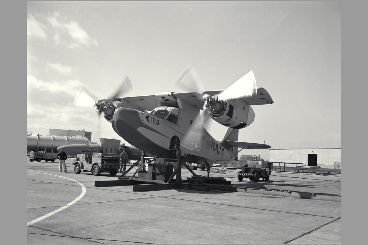
KAMAN K-16-B aircraft

Mysterious B Ring
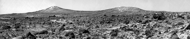
Twin Peaks B/W

B Ring Irregularities

B Ring in the Negative
The B Ring Variations

B Ring Terminus

A View of Saturn B-ring
Saturn B rings
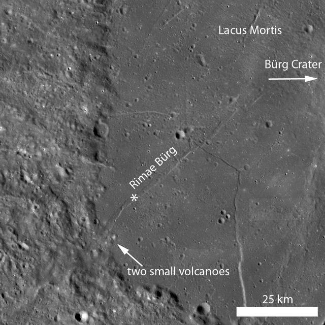
Rimae Bürg
Saturn B-ring

Saturn B and C-rings
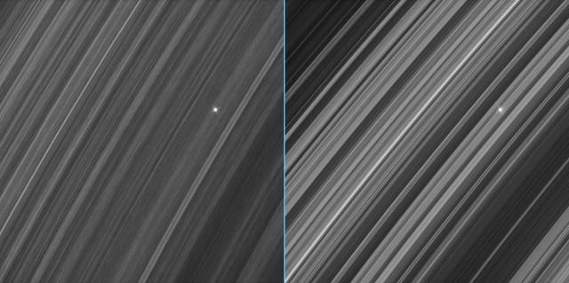
This image shows a region in Saturn's outer B ring. NASA's Cassini spacecraft viewed this area at a level of detail twice as high as it had ever been observed before. The view here is of the outer edge of the B ring, at left, which is perturbed by the most powerful gravitational resonance in the rings: the "2:1 resonance" with the icy moon Mimas. This means that, for every single orbit of Mimas, the ring particles at this specific distance from Saturn orbit the planet twice. This results in a regular tugging force that perturbs the particles in this location. A lot of structure is visible in the zone near the edge on the left. This is likely due to some combination of the gravity of embedded objects too small to see, or temporary clumping triggered by the action of the resonance itself. Scientists informally refer to this type of structure as "straw." This image was taken using a fairly long exposure, causing the embedded clumps to smear into streaks as they moved in their orbits. Later Cassini orbits will bring shorter exposures of the same region, which will give researchers a better idea of what these clumps look like. But in this case, the smearing does help provide a clearer idea of how the clumps are moving. This image is a lightly processed version, with minimal enhancement; this version preserves all original details present in the image. Another other version (Figure 1) has been processed to remove the small bright blemishes due to cosmic rays and charged particle radiation near the planet -- a more aesthetically pleasing image, but with a slight softening of the finest details. The image was taken in visible light with the Cassini spacecraft wide-angle camera on Dec. 18, 2016. The view was obtained at a distance of approximately 32,000 miles (52,000 kilometers) from the rings and looks toward the unilluminated side of the rings. Image scale is about a quarter-mile (360 meters) per pixel. http://photojournal.jpl.nasa.gov/catalog/PIA21057
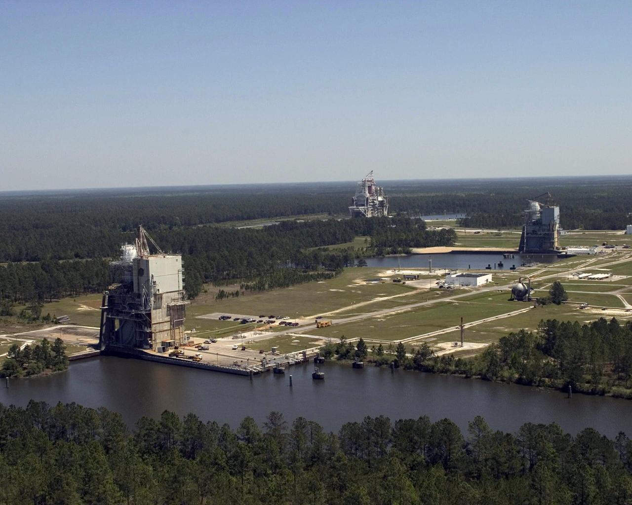
SSC's A-1, A-2 and B test stands were built in the early 1960s to test the first and second stages of the Apollo Saturn V rocket that safely transported Americans to the moon. The A-1 Stand (foreground) will soon test the J-2X engines that will power the rockets to take Americans back to the moon.

This image shows brown dwarf HIP 79124 B, located 23 times as far from its host star as Earth is from the sun. The vortex coronagraph, an instrument at the W.M. Keck Observatory, was used to suppress light from the much brighter host star, allowing its dim companion to be imaged for the first time. http://photojournal.jpl.nasa.gov/catalog/PIA21417
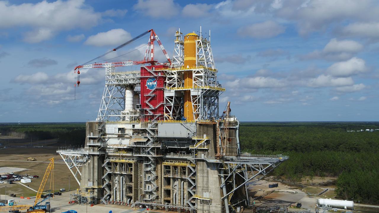
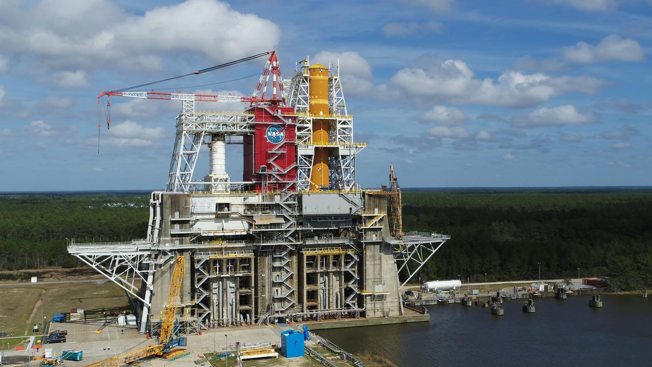
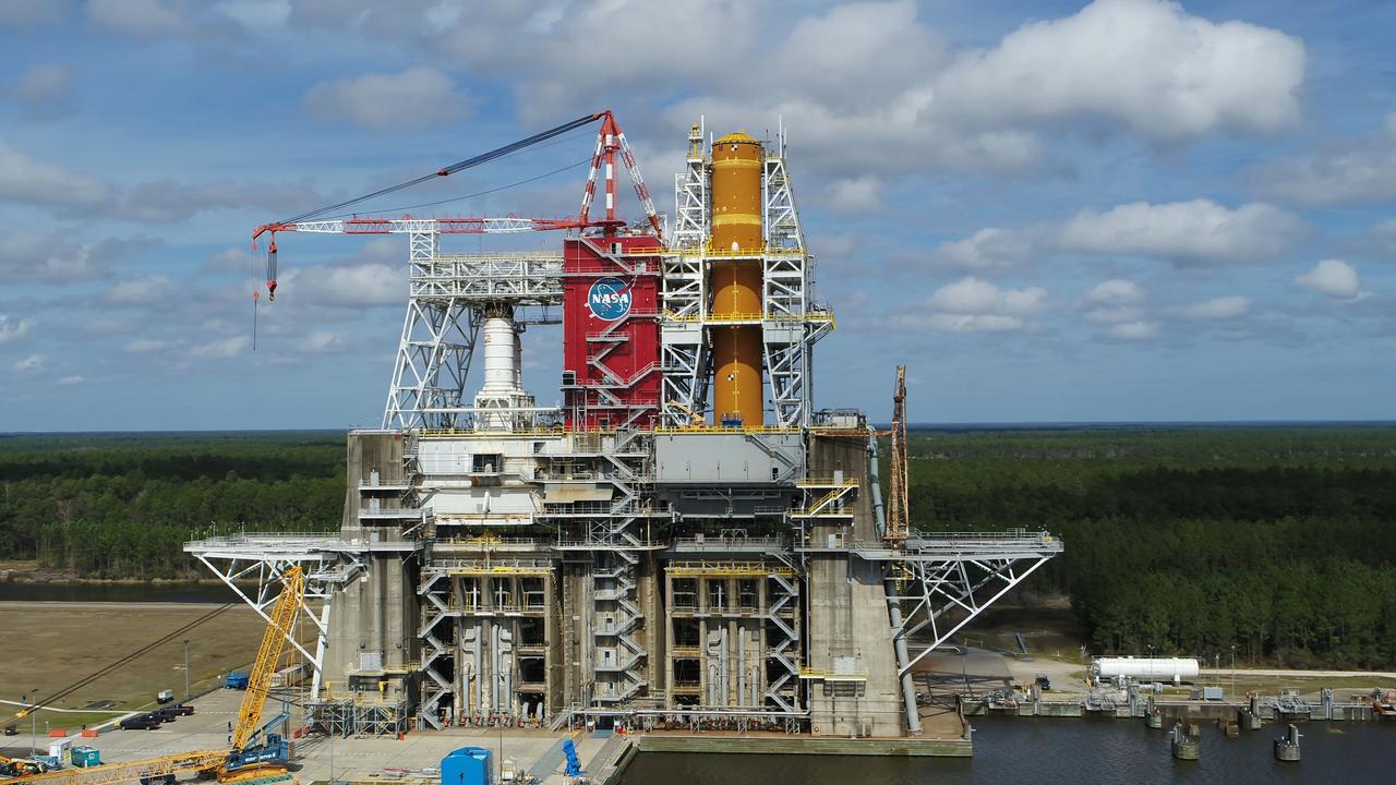
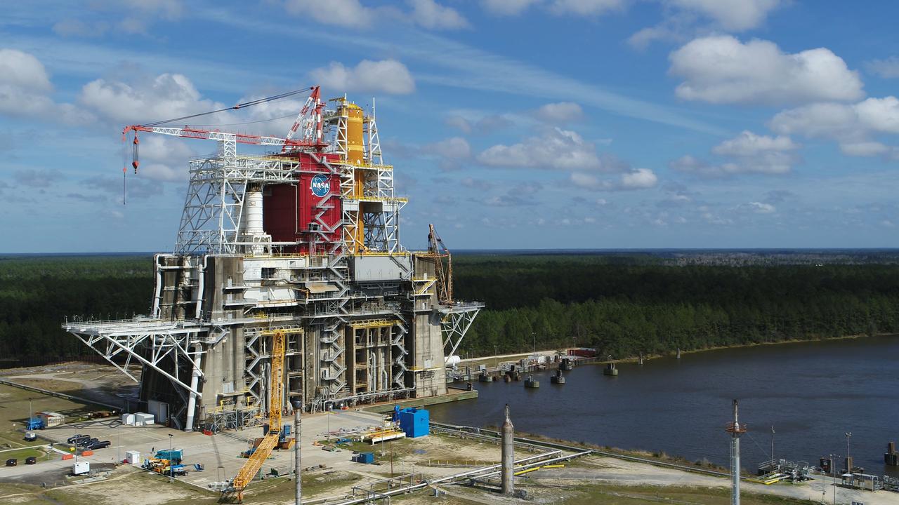
A NASA drone photo offers a bird’s-eye view of the B-2 Test Stand at NASA’s Stennis Space Center with the first flight core stage for NASA’s new Space Launch System (SLS) installed for Green Run testing. The SLS core stage is undergoing a series of tests on its integrated systems prior to its use on the Artemis I mission. NASA is building SLS to return humans, including the first woman, to the Moon as part of the Artemis program and to prepare for eventual missions to Mars. The Green Run series at Stennis culminates with a hot fire of the core stage’s four RS-25 engines, just as during an actual launch.

B Ring Straw-like Clumps

Outer edge of Saturn B-ring

The Cassini spacecraft looks closely at the outer B ring and the Cassini Division, revealing clump-like structures in the outer edge of the B ring.

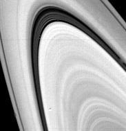
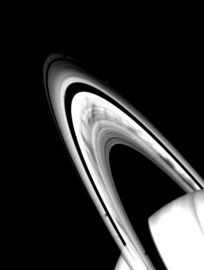
Saturn B ring is spread out in all its glory in this image from NASAS Cassini spacecraft. Scientists are trying to better understand the origin and nature of the various structures seen in the B ring.
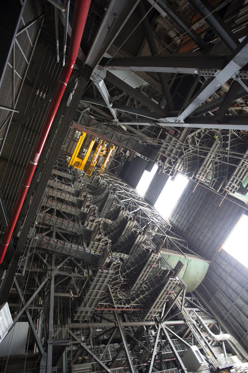
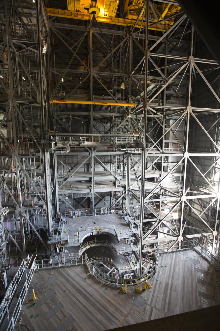
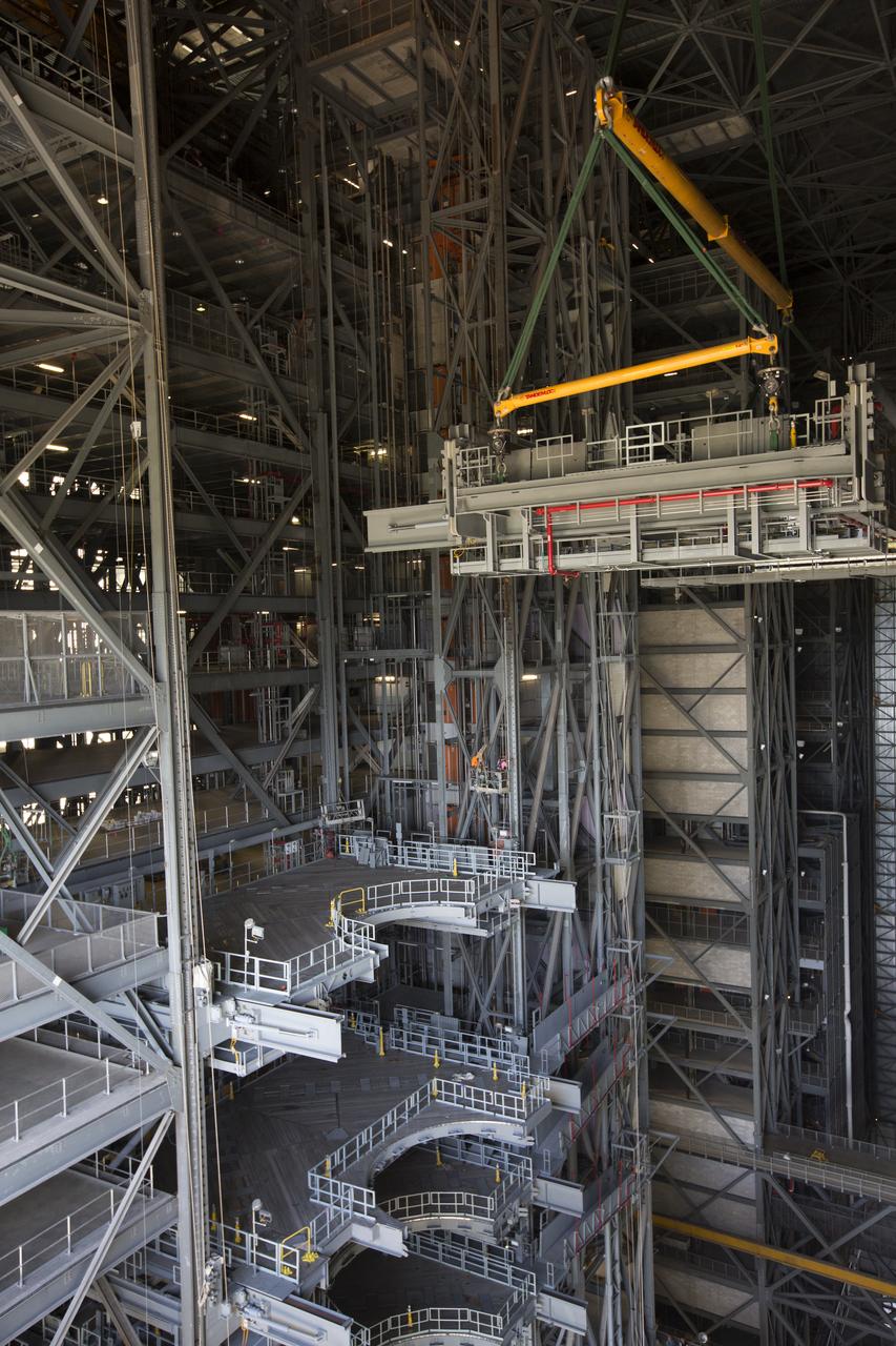
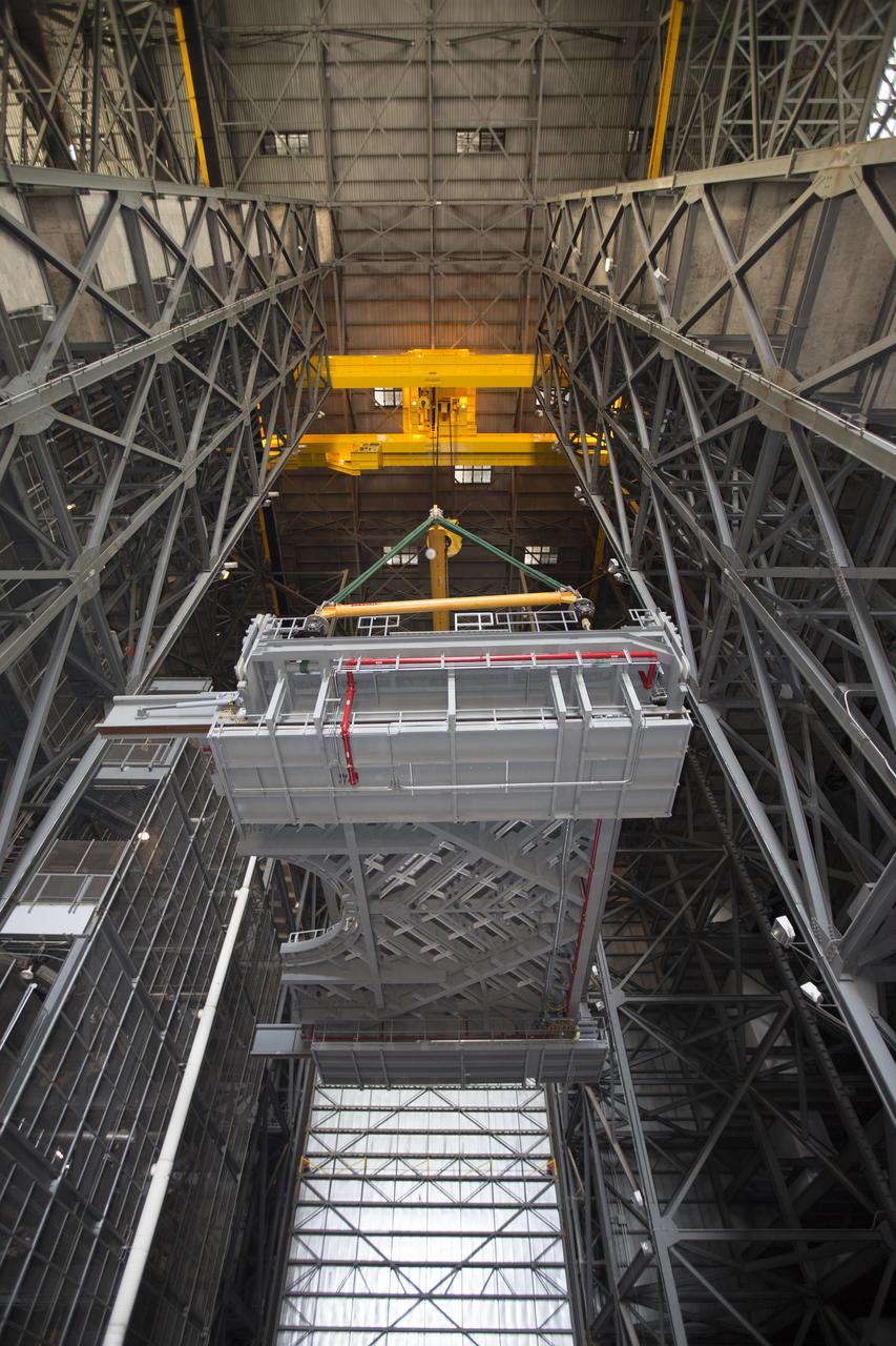
High up in the Vehicle Assembly Building (VAB) at NASA's Kennedy Space Center in Florida, a crane lowers the second half of the B-level work platforms, B north, for NASA's Space Launch System (SLS) rocket, for installation in High Bay 3. The B platform will be installed on the north side of high bay. In view below are eight levels of previously installed platforms. The B platforms are the ninth of 10 levels of work platforms that will surround and provide access to the SLS rocket and Orion spacecraft for Exploration Mission 1. The Ground Systems Development and Operations Program is overseeing upgrades and modifications to VAB High Bay 3, including installation of the new work platforms, to prepare for NASA’s Journey to Mars.
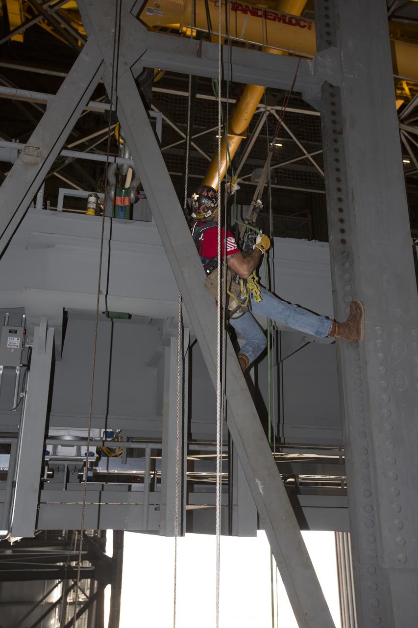
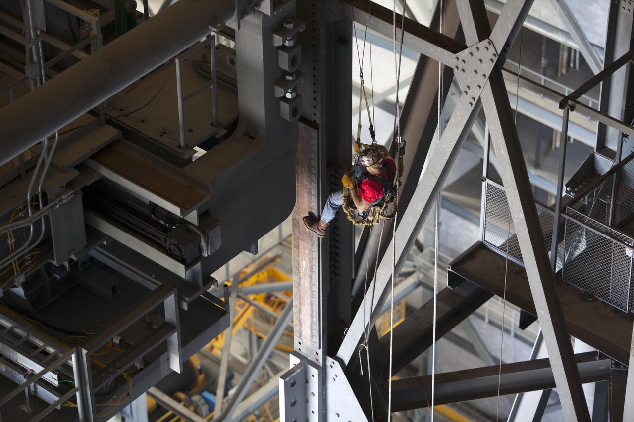
A construction worker wearing a safety harness and tethered lines assists with the installation of the second half of the B-level work platforms, B north, for NASA’s Space Launch System (SLS) rocket, high up in the Vehicle Assembly Building (VAB) at NASA’s Kennedy Space Center in Florida. The B platform will be installed on the north side of High Bay 3. The B platforms are the ninth of 10 levels of work platforms that will surround and provide access to the SLS rocket and Orion spacecraft for Exploration Mission 1. The Ground Systems Development and Operations Program is overseeing upgrades and modifications to VAB High Bay 3, including installation of the new work platforms, to prepare for NASA’s Journey to Mars.
High up in the Vehicle Assembly Building (VAB) at NASA's Kennedy Space Center in Florida, a crane lowers the second half of the B-level work platforms, B north, for NASA's Space Launch System (SLS) rocket, for installation in High Bay 3. The B platform will be installed on the north side of high bay. In view below are several levels of previously installed platforms. The B platforms are the ninth of 10 levels of work platforms that will surround and provide access to the SLS rocket and Orion spacecraft for Exploration Mission 1. The Ground Systems Development and Operations Program is overseeing upgrades and modifications to VAB High Bay 3, including installation of the new work platforms, to prepare for NASA’s Journey to Mars.
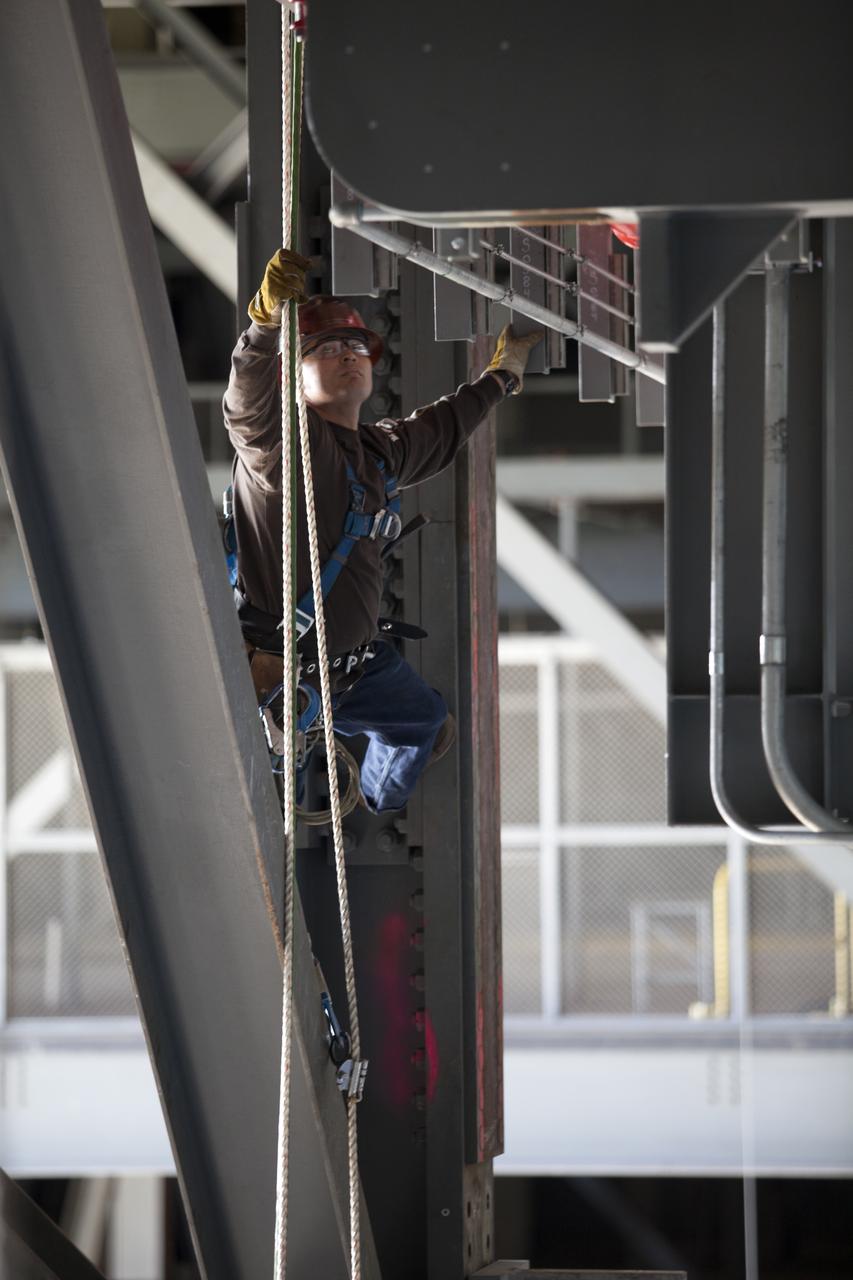
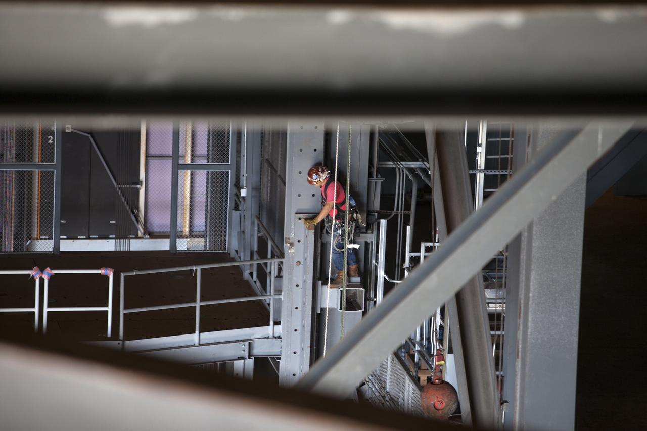
A construction worker wearing a safety harness and tethered lines prepares to assist with the installation of the second half of the B-level work platforms, B north, for NASA’s Space Launch System (SLS) rocket, high up in the Vehicle Assembly Building (VAB) at NASA’s Kennedy Space Center in Florida. The B platform will be installed on the north side of High Bay 3. The B platforms are the ninth of 10 levels of work platforms that will surround and provide access to the SLS rocket and Orion spacecraft for Exploration Mission 1. The Ground Systems Development and Operations Program is overseeing upgrades and modifications to VAB High Bay 3, including installation of the new work platforms, to prepare for NASA’s Journey to Mars.
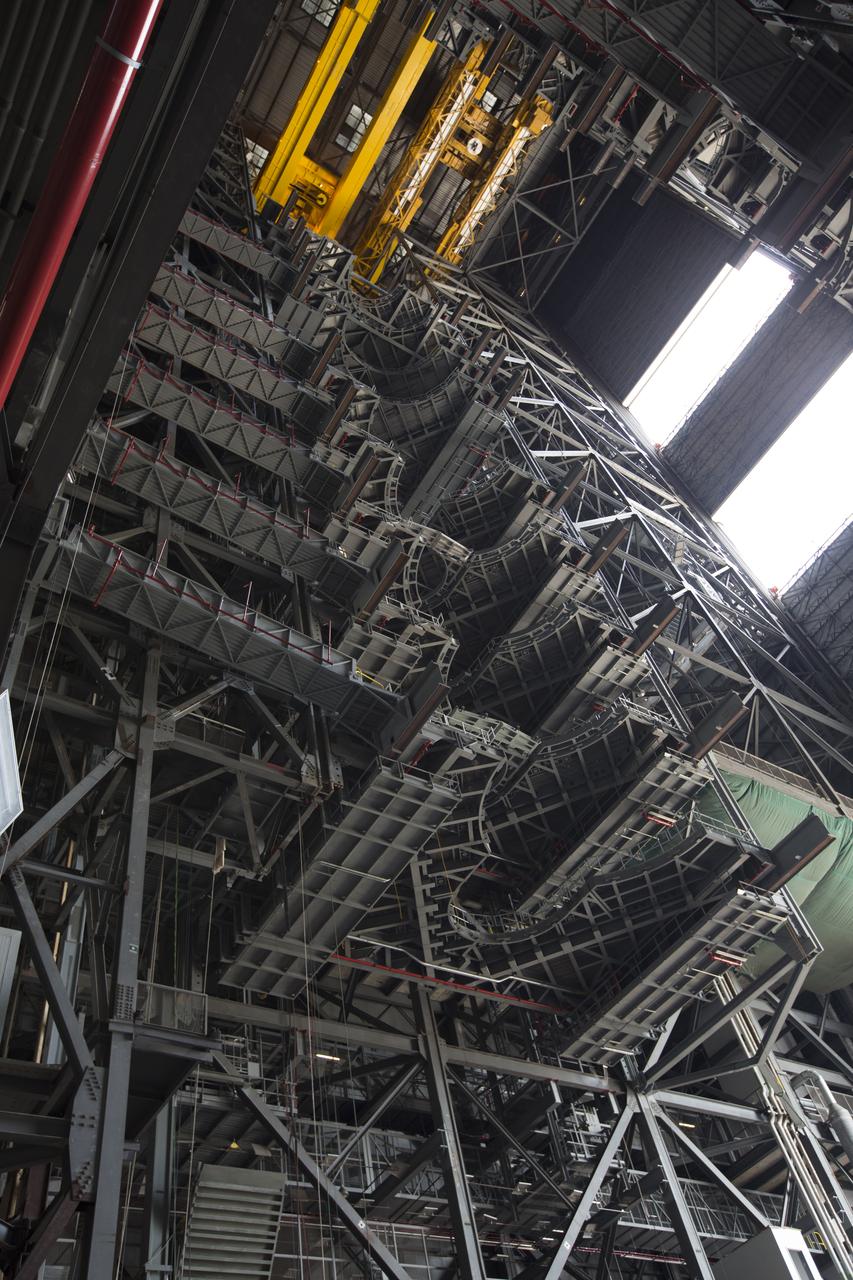
High up in the Vehicle Assembly Building (VAB) at NASA's Kennedy Space Center in Florida, a crane lowers the second half of the B-level work platforms, B north, for NASA's Space Launch System (SLS) rocket, for installation in High Bay 3. The B platform will be installed on the north side of high bay. In view below are eight levels of previously installed platforms. The B platforms are the ninth of 10 levels of work platforms that will surround and provide access to the SLS rocket and Orion spacecraft for Exploration Mission 1. The Ground Systems Development and Operations Program is overseeing upgrades and modifications to VAB High Bay 3, including installation of the new work platforms, to prepare for NASA’s Journey to Mars.
A construction worker wearing a safety harness and tethered lines prepares to assist with the installation of the second half of the B-level work platforms, B north, for NASA’s Space Launch System (SLS) rocket, high up in the Vehicle Assembly Building (VAB) at NASA’s Kennedy Space Center in Florida. The B platform will be installed on the north side of High Bay 3. The B platforms are the ninth of 10 levels of work platforms that will surround and provide access to the SLS rocket and Orion spacecraft for Exploration Mission 1. The Ground Systems Development and Operations Program is overseeing upgrades and modifications to VAB High Bay 3, including installation of the new work platforms, to prepare for NASA’s Journey to Mars.
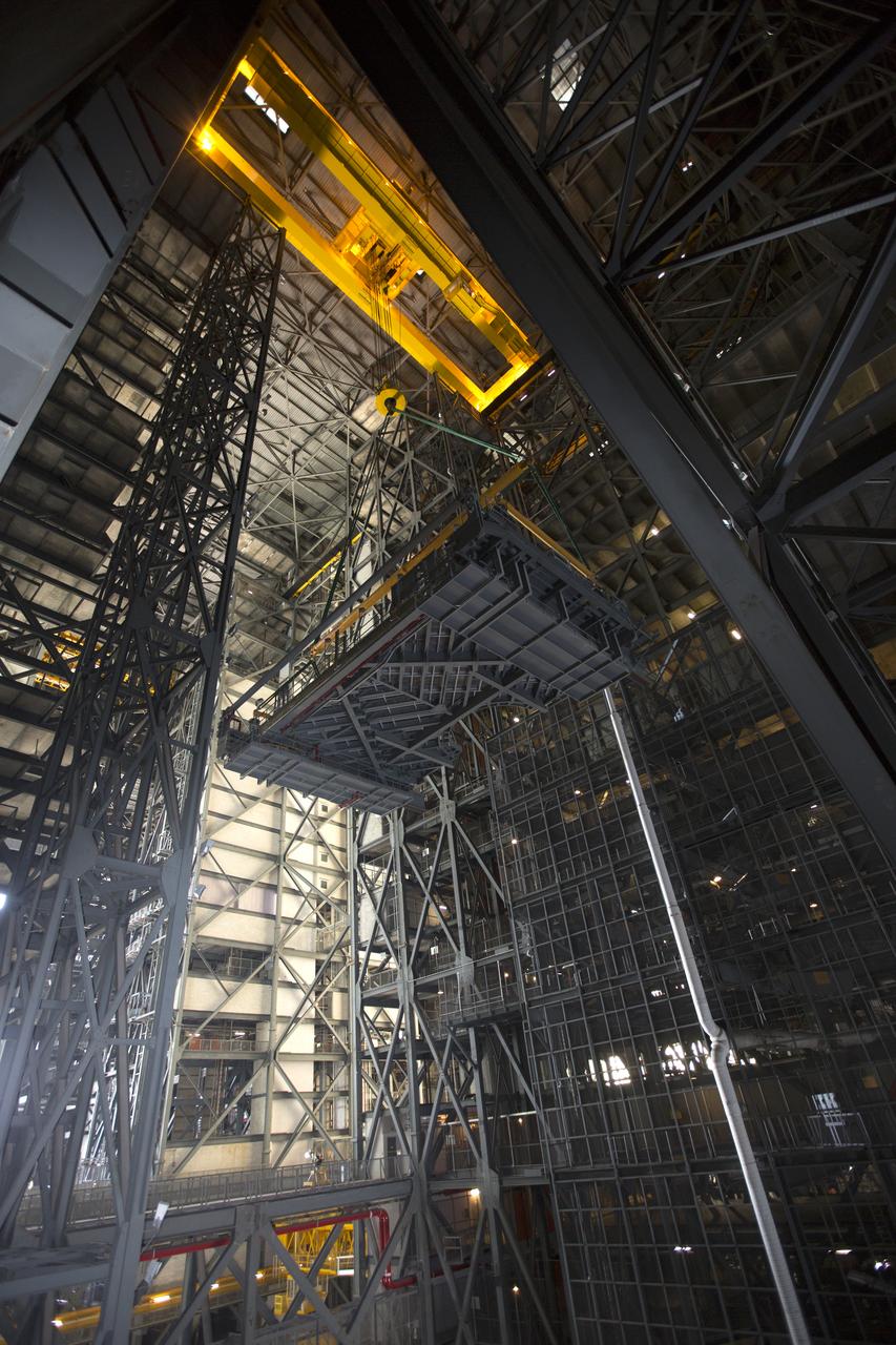
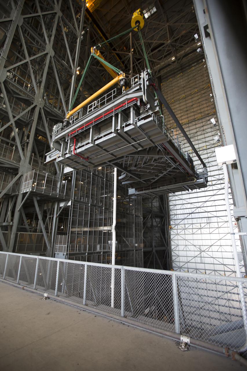
A crane lifts the second half of the B-level work platforms, B north, for NASA's Space Launch System (SLS) rocket, high up in the transfer aisle of the Vehicle Assembly Building (VAB) at NASA’s Kennedy Space Center in Florida. The B north platform will lowered into High Bay 3 for installation on the north side of the high bay. The B platforms are the ninth of 10 levels of work platforms that will surround and provide access to the SLS rocket and Orion spacecraft for Exploration Mission 1. The Ground Systems Development and Operations Program is overseeing upgrades and modifications to VAB High Bay 3, including installation of the new work platforms, to prepare for NASA’s Journey to Mars.
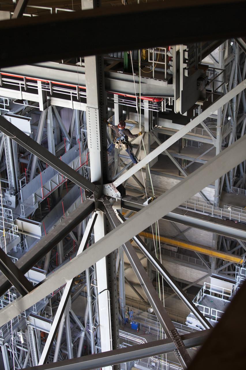
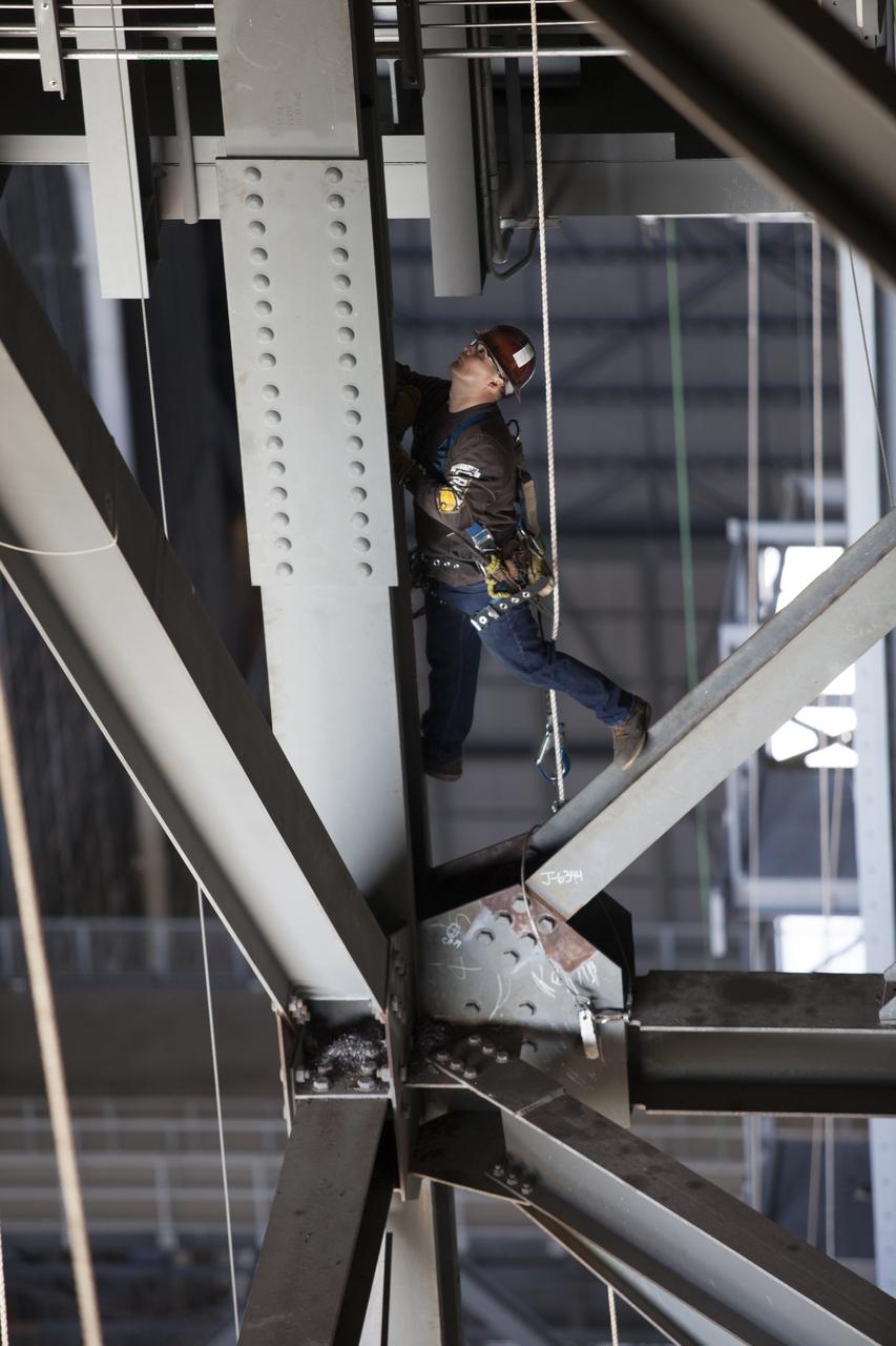
A construction worker wearing a safety harness and tethered lines monitors the progress during the installation of the second half of the B-level work platforms, B north, for NASA’s Space Launch System (SLS) rocket, high up in the Vehicle Assembly Building (VAB) at NASA’s Kennedy Space Center in Florida. The B platform will be installed on the north side of High Bay 3. The B platforms are the ninth of 10 levels of work platforms that will surround and provide access to the SLS rocket and Orion spacecraft for Exploration Mission 1. The Ground Systems Development and Operations Program is overseeing upgrades and modifications to VAB High Bay 3, including installation of the new work platforms, to prepare for NASA’s Journey to Mars.
A construction worker wearing a safety harness and tethered lines monitors the progress during the installation of the second half of the B-level work platforms, B north, for NASA’s Space Launch System (SLS) rocket, high up in the Vehicle Assembly Building (VAB) at NASA’s Kennedy Space Center in Florida. The B platform will be installed on the north side of High Bay 3. The B platforms are the ninth of 10 levels of work platforms that will surround and provide access to the SLS rocket and Orion spacecraft for Exploration Mission 1. The Ground Systems Development and Operations Program is overseeing upgrades and modifications to VAB High Bay 3, including installation of the new work platforms, to prepare for NASA’s Journey to Mars.
A construction worker wearing a safety harness and tethered lines prepares to assist with the installation of the second half of the B-level work platforms, B north, for NASA’s Space Launch System (SLS) rocket, high up in the Vehicle Assembly Building (VAB) at NASA’s Kennedy Space Center in Florida. The B platform will be installed on the north side of High Bay 3. The B platforms are the ninth of 10 levels of work platforms that will surround and provide access to the SLS rocket and Orion spacecraft for Exploration Mission 1. The Ground Systems Development and Operations Program is overseeing upgrades and modifications to VAB High Bay 3, including installation of the new work platforms, to prepare for NASA’s Journey to Mars.
High up in the Vehicle Assembly Building (VAB) at NASA's Kennedy Space Center in Florida, a crane lowers the second half of the B-level work platforms, B north, for NASA's Space Launch System (SLS) rocket, for installation in High Bay 3. The B platform will be installed on the north side of high bay. The B platforms are the ninth of 10 levels of work platforms that will surround and provide access to the SLS rocket and Orion spacecraft for Exploration Mission 1. The Ground Systems Development and Operations Program is overseeing upgrades and modifications to VAB High Bay 3, including installation of the new work platforms, to prepare for NASA’s Journey to Mars.
In this angle looking up, this photograph shows the crew access arm connected to NASA’s Artemis II SLS (Space Launch System) rocket and Orion spacecraft, secured to the mobile launcher at Launch Complex 39B at NASA’s Kennedy Space Center in Florida on Tuesday, Jan. 20, 2026. The Artemis II test flight will take Commander Reid Wiseman, Pilot Victor Glover, and Mission Specialist Christina Koch from NASA, and Mission Specialist Jeremy Hansen from the CSA (Canadian Space Agency), on a 10-day journey no earlier than 6:24 p.m. EDT on Wednesday, April 1.
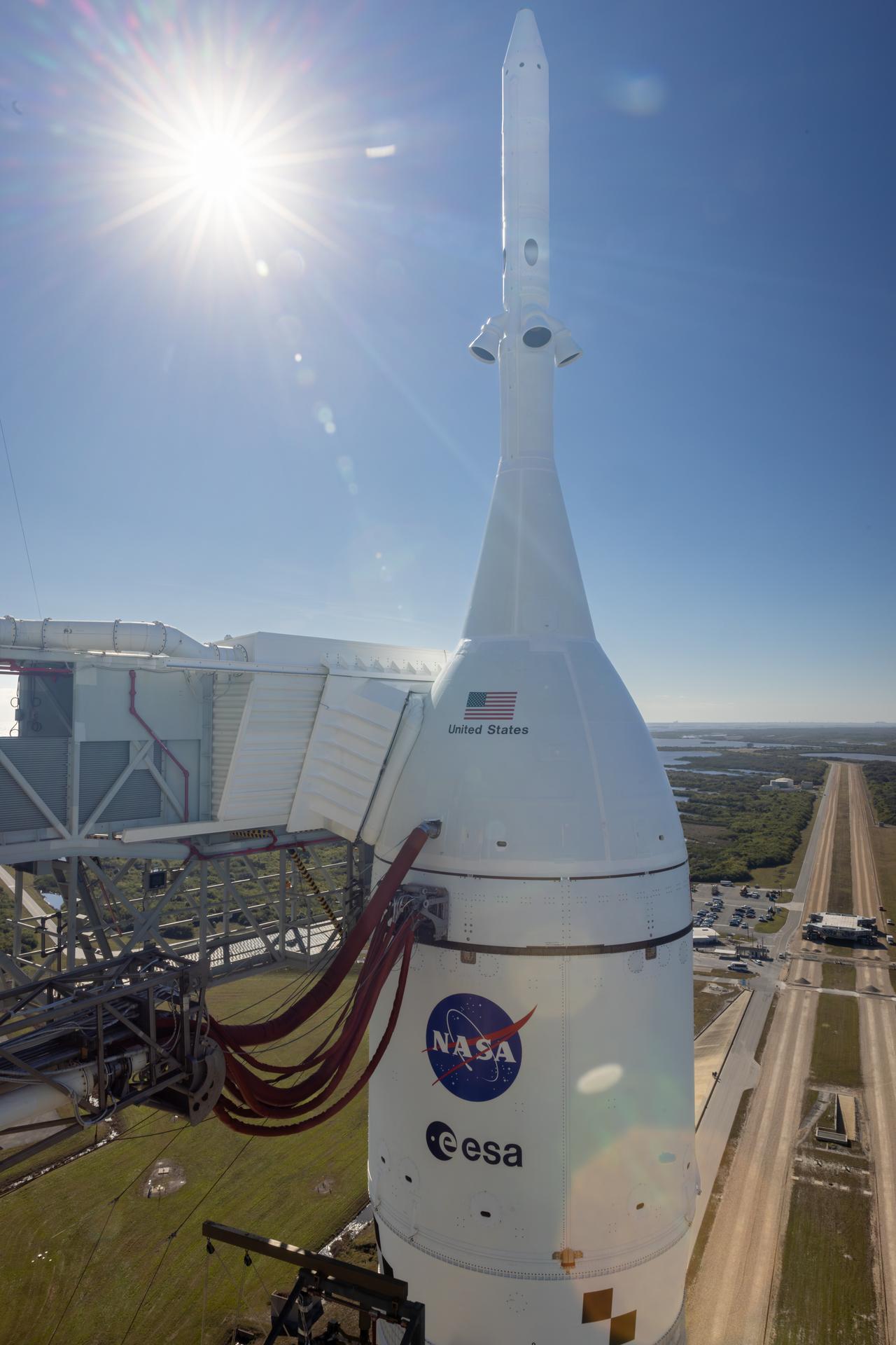
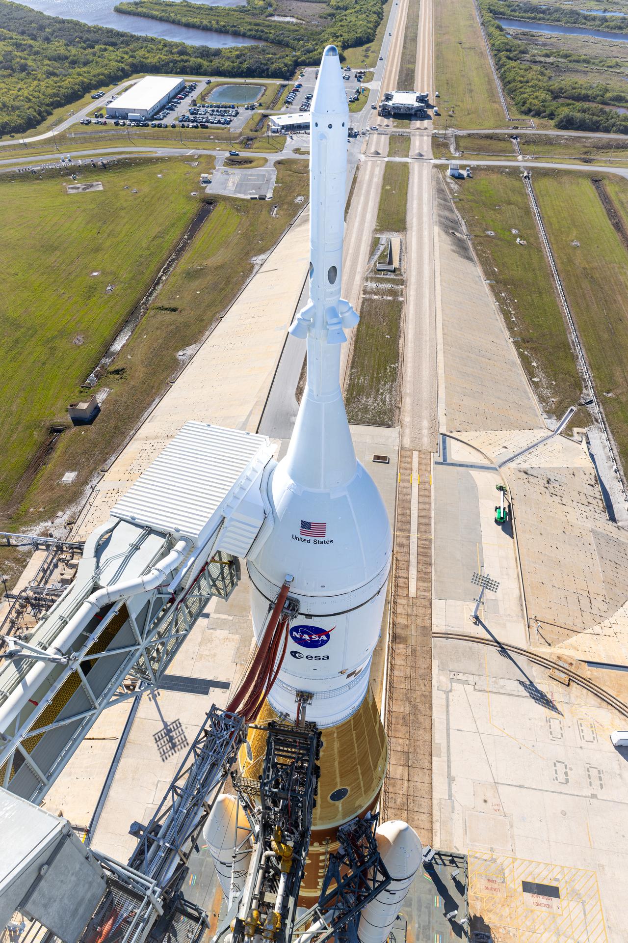
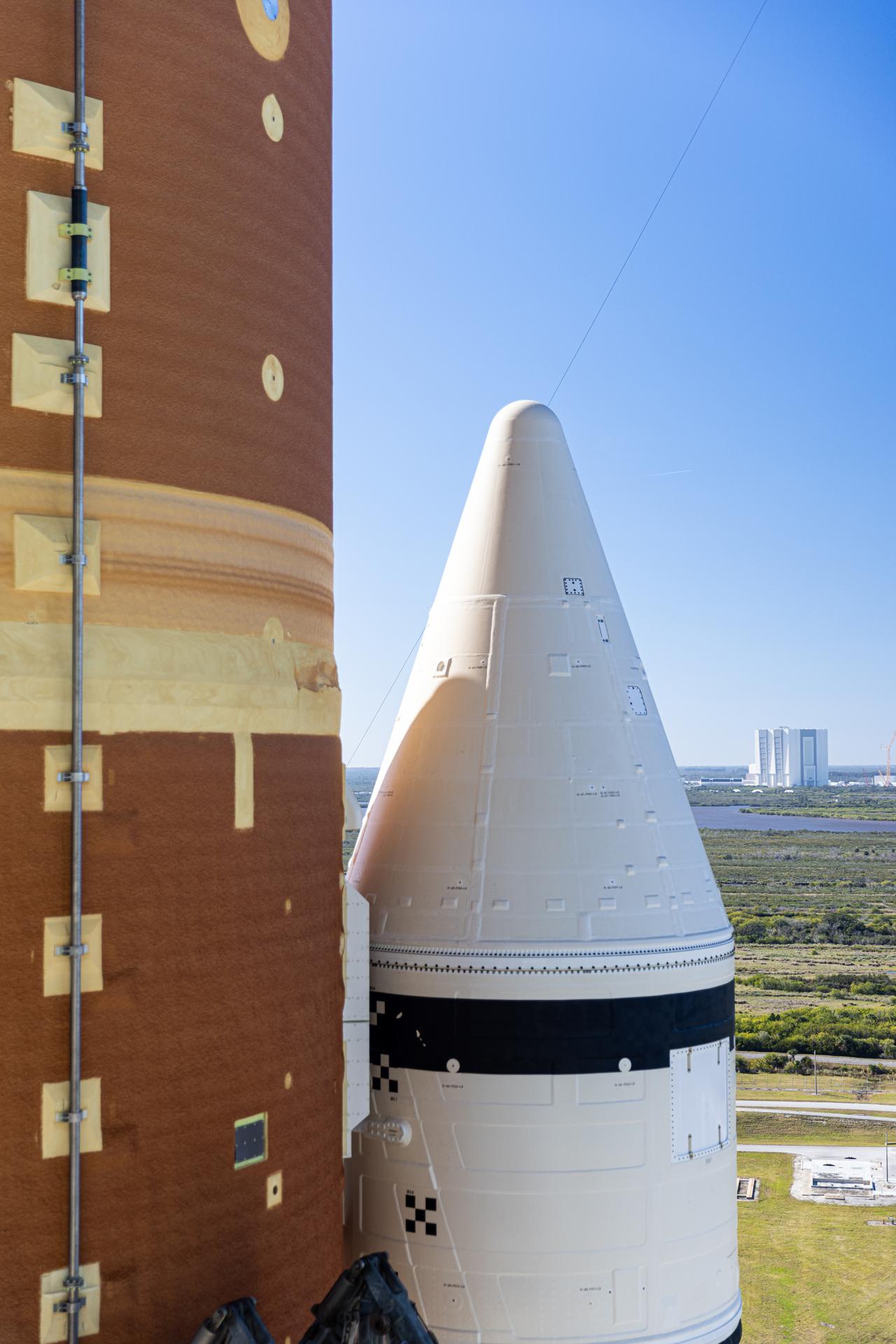
A closeup view of NASA’s Orion spacecraft with the launch abort system atop NASA’s Artemis II SLS (Space Launch System) rocket at Launch Complex 39B at NASA’s Kennedy Space Center in Florida on Tuesday, Jan. 20, 2026. The Artemis II test flight will take Commander Reid Wiseman, Pilot Victor Glover, and Mission Specialist Christina Koch from NASA, and Mission Specialist Jeremy Hansen from the CSA (Canadian Space Agency), on a 10-day journey no earlier than 6:24 p.m. EDT on Wednesday, April 1.
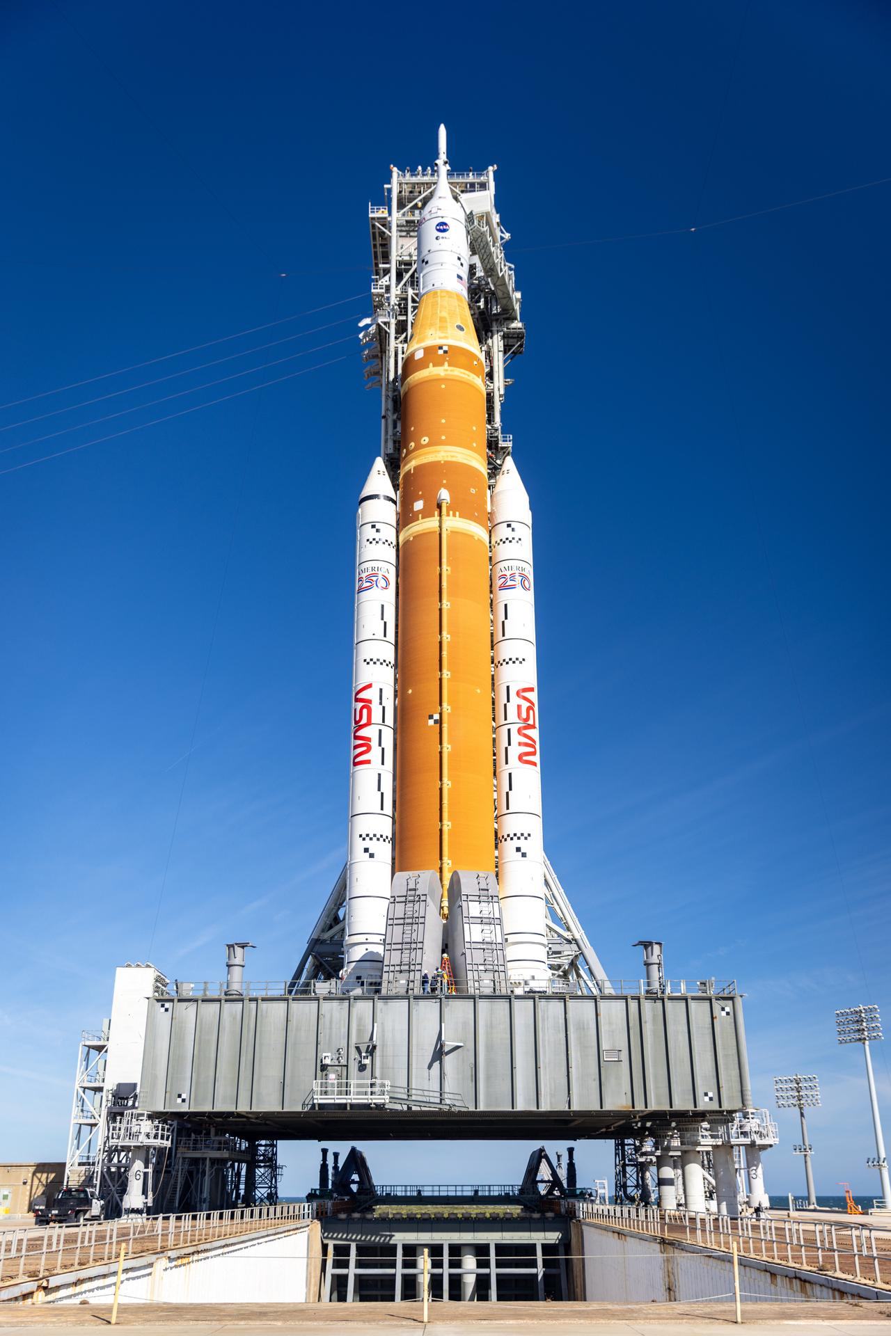
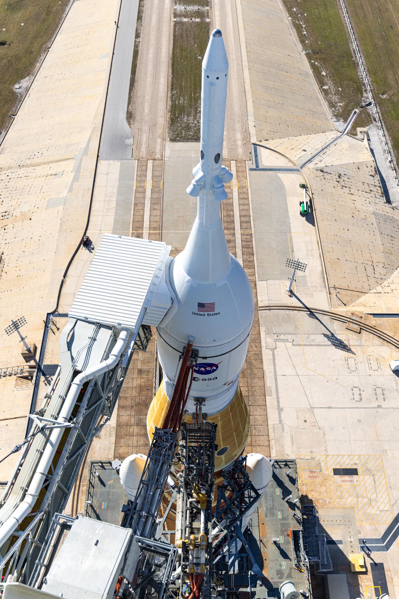
NASA’s Artemis II SLS (Space Launch System) rocket and Orion spacecraft, secured to the mobile launcher, stands vertical at Launch Complex 39B at NASA’s Kennedy Space Center in Florida on Tuesday, Jan. 20, 2026. The Artemis II test flight will take Commander Reid Wiseman, Pilot Victor Glover, and Mission Specialist Christina Koch from NASA, and Mission Specialist Jeremy Hansen from the CSA (Canadian Space Agency), on a 10-day journey no earlier than 6:24 p.m. EDT on Wednesday, April 1.
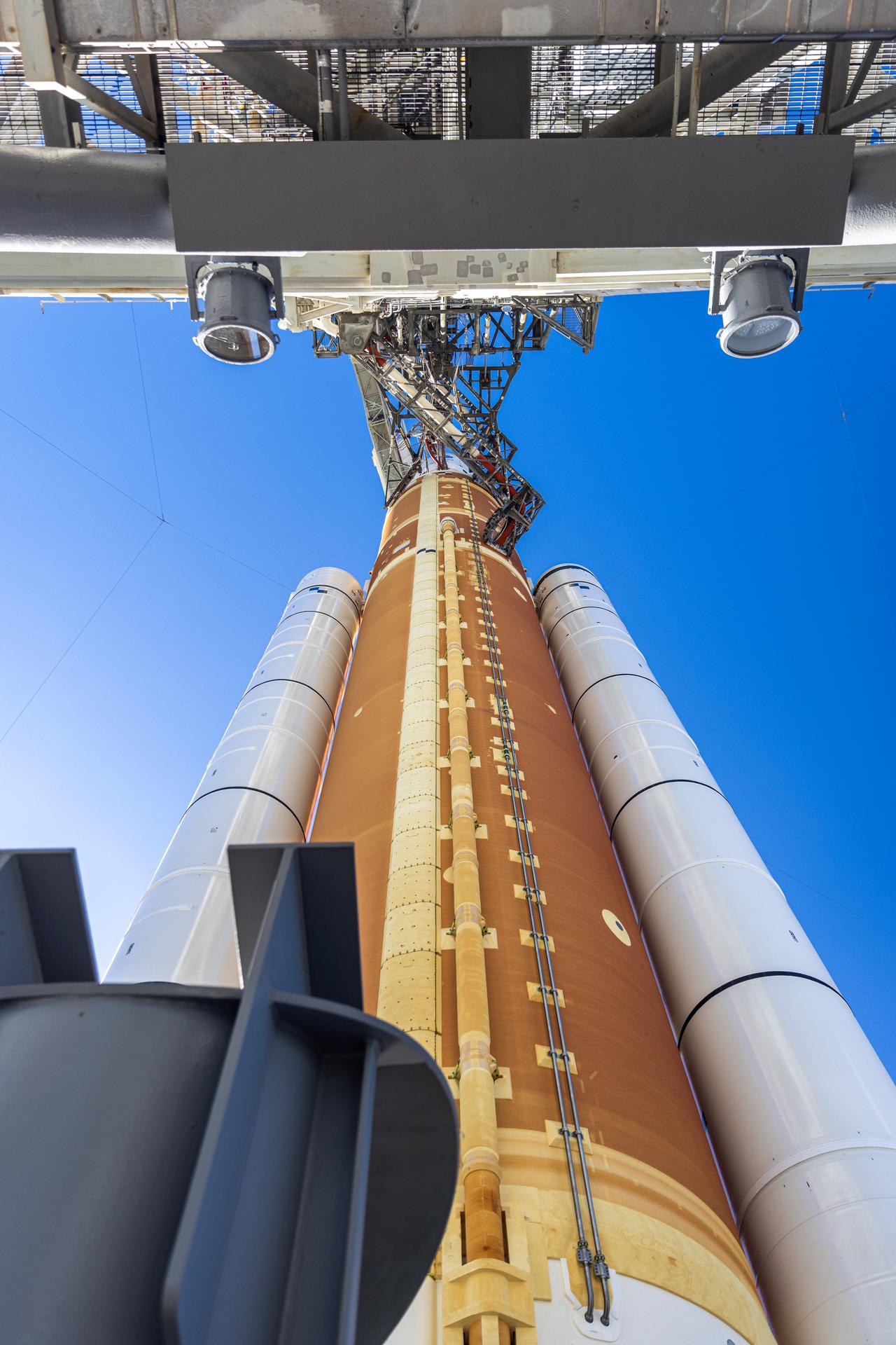
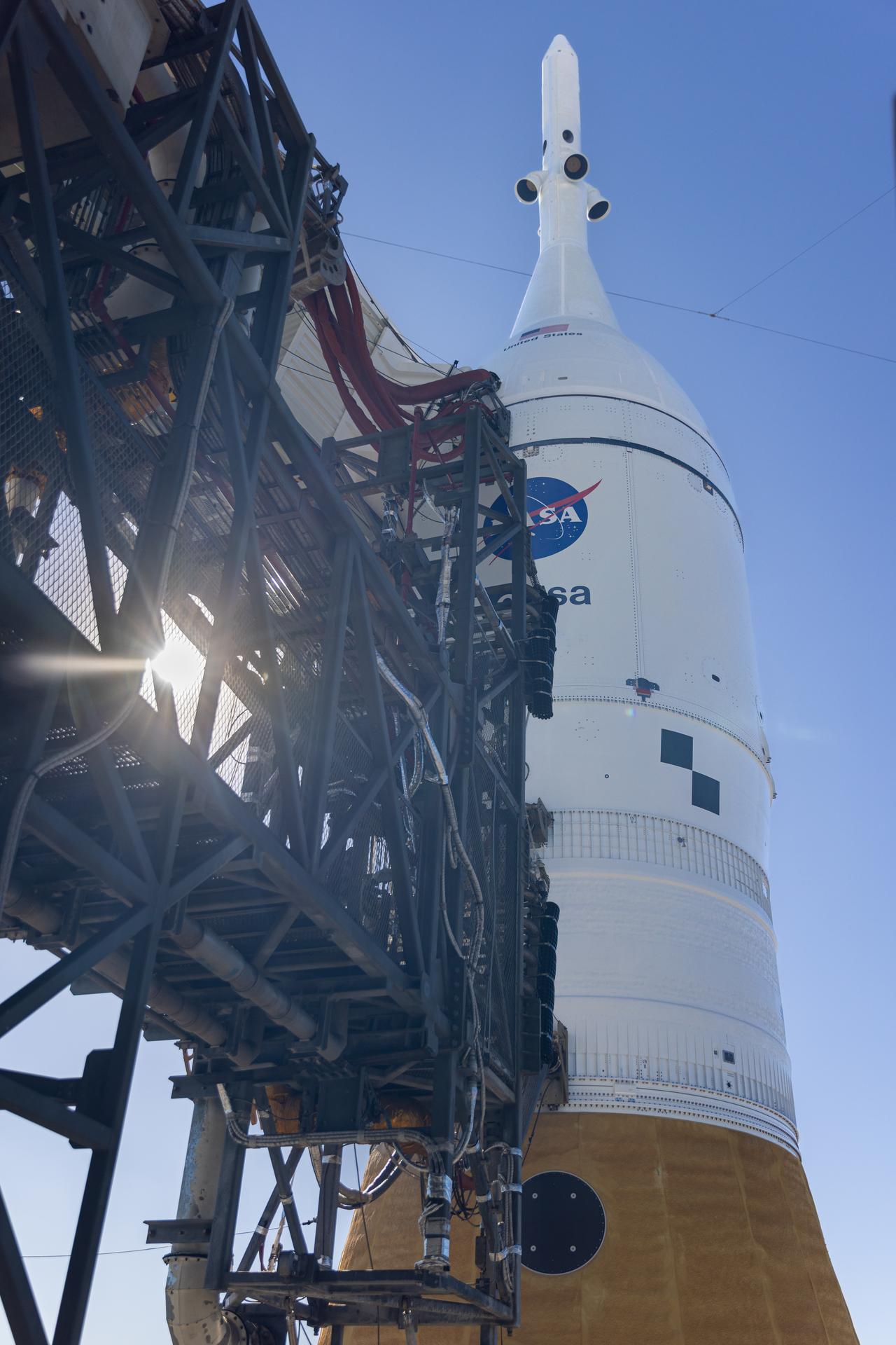
In this angle looking up, this photograph shows NASA’s Artemis II SLS (Space Launch System) rocket and Orion spacecraft, secured to the mobile launcher at Launch Complex 39B at NASA’s Kennedy Space Center in Florida on Tuesday, Jan. 20, 2026. The Artemis II test flight will take Commander Reid Wiseman, Pilot Victor Glover, and Mission Specialist Christina Koch from NASA, and Mission Specialist Jeremy Hansen from the CSA (Canadian Space Agency), on a 10-day journey no earlier than 6:24 p.m. EDT on Wednesday, April 1.
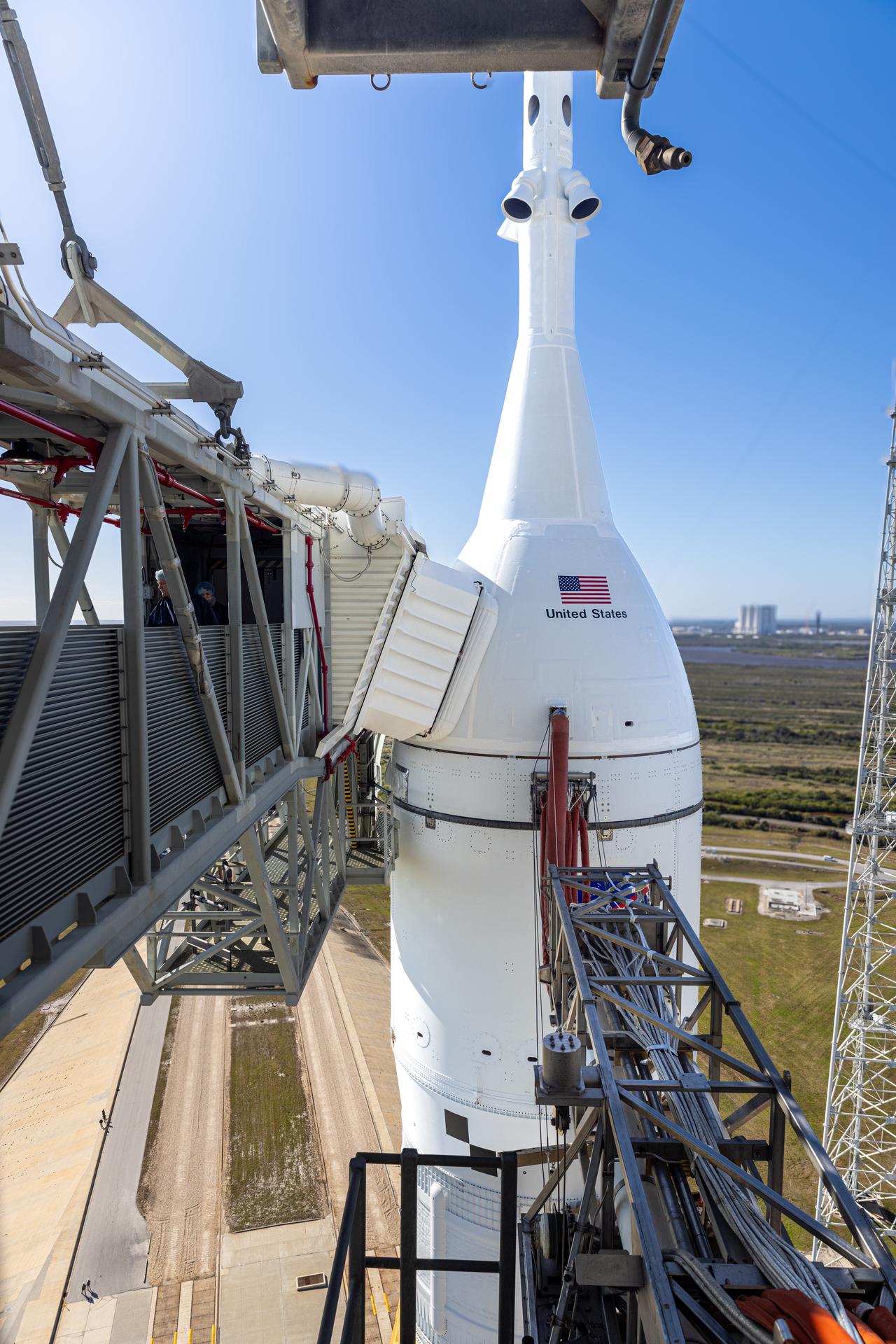
A closeup view of the crew access arm connected to NASA’s Orion spacecraft with the launch abort system atop NASA’s Artemis II SLS (Space Launch System) rocket at Launch Complex 39B at NASA’s Kennedy Space Center in Florida on Tuesday, Jan. 20, 2026. The Artemis II test flight will take Commander Reid Wiseman, Pilot Victor Glover, and Mission Specialist Christina Koch from NASA, and Mission Specialist Jeremy Hansen from the CSA (Canadian Space Agency), on a 10-day journey no earlier than 6:24 p.m. EDT on Wednesday, April 1.
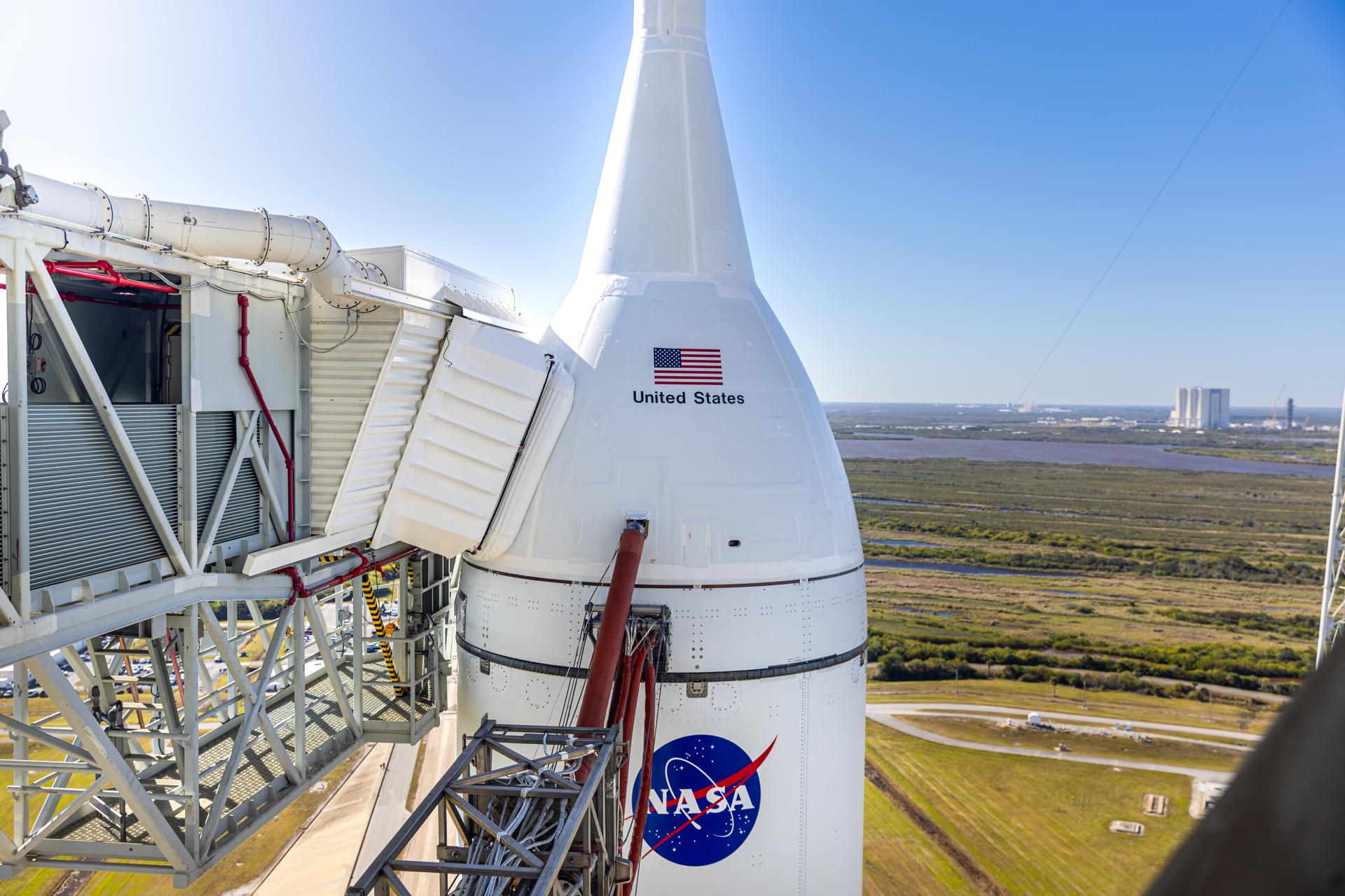
A closeup view of NASA’s Orion spacecraft with the launch abort system atop NASA’s Artemis II SLS (Space Launch System) rocket at Launch Complex 39B at NASA’s Kennedy Space Center in Florida on Tuesday, Jan. 20, 2026. The Artemis II test flight will take Commander Reid Wiseman, Pilot Victor Glover, and Mission Specialist Christina Koch from NASA, and Mission Specialist Jeremy Hansen from the CSA (Canadian Space Agency), on a 10-day journey no earlier than 6:24 p.m. EDT on Wednesday, April 1.
A closeup view of the crew access arm connected to NASA’s Orion spacecraft with the launch abort system atop NASA’s Artemis II SLS (Space Launch System) rocket at Launch Complex 39B at NASA’s Kennedy Space Center in Florida on Tuesday, Jan. 20, 2026. The Artemis II test flight will take Commander Reid Wiseman, Pilot Victor Glover, and Mission Specialist Christina Koch from NASA, and Mission Specialist Jeremy Hansen from the CSA (Canadian Space Agency), on a 10-day journey no earlier than 6:24 p.m. EDT on Wednesday, April 1.
A closeup view of the crew access arm connected to NASA’s Orion spacecraft with the launch abort system atop NASA’s Artemis II SLS (Space Launch System) rocket at Launch Complex 39B at NASA’s Kennedy Space Center in Florida on Tuesday, Jan. 20, 2026. The Artemis II test flight will take Commander Reid Wiseman, Pilot Victor Glover, and Mission Specialist Christina Koch from NASA, and Mission Specialist Jeremy Hansen from the CSA (Canadian Space Agency), on a 10-day journey no earlier than 6:24 p.m. EDT on Wednesday, April 1.
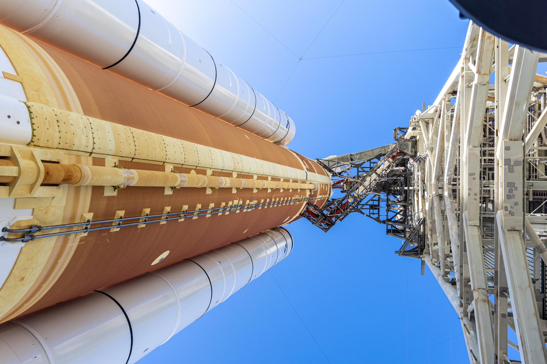
In this angle looking up, this photograph shows NASA’s Artemis II SLS (Space Launch System) rocket and Orion spacecraft, secured to the mobile launcher at Launch Complex 39B at NASA’s Kennedy Space Center in Florida on Tuesday, Jan. 20, 2026. The Artemis II test flight will take Commander Reid Wiseman, Pilot Victor Glover, and Mission Specialist Christina Koch from NASA, and Mission Specialist Jeremy Hansen from the CSA (Canadian Space Agency), on a 10-day journey no earlier than 6:24 p.m. EDT on Wednesday, April 1.
A closeup view of the crew access arm connected to NASA’s Orion spacecraft with the launch abort system atop NASA’s Artemis II SLS (Space Launch System) rocket at Launch Complex 39B at NASA’s Kennedy Space Center in Florida on Tuesday, Jan. 20, 2026. The Artemis II test flight will take Commander Reid Wiseman, Pilot Victor Glover, and Mission Specialist Christina Koch from NASA, and Mission Specialist Jeremy Hansen from the CSA (Canadian Space Agency), on a 10-day journey no earlier than 6:24 p.m. EDT on Wednesday, April 1.
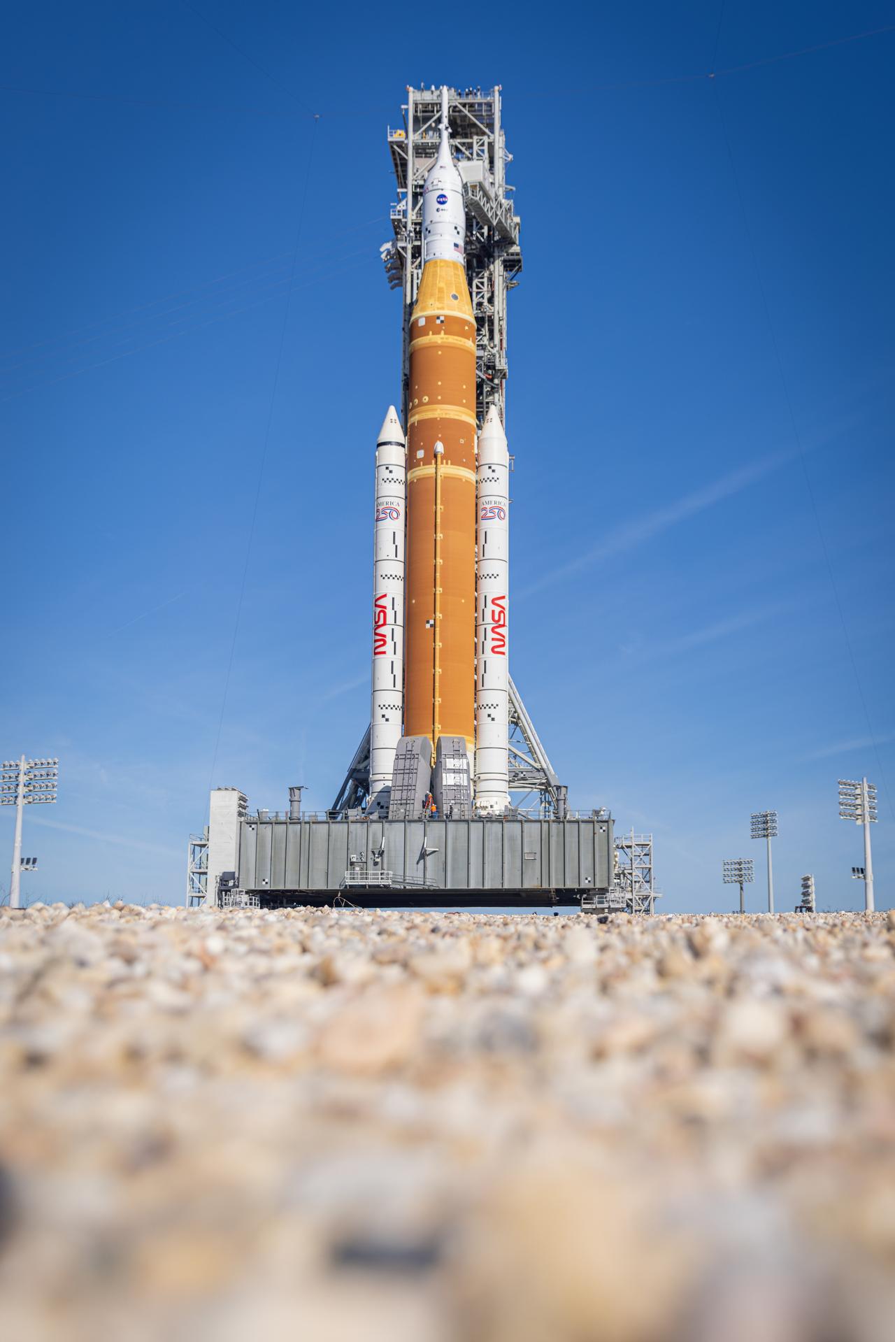
NASA’s Artemis II SLS (Space Launch System) rocket and Orion spacecraft, secured to the mobile launcher, stands vertical at Launch Complex 39B at NASA’s Kennedy Space Center in Florida on Tuesday, Jan. 20, 2026. The Artemis II test flight will take Commander Reid Wiseman, Pilot Victor Glover, and Mission Specialist Christina Koch from NASA, and Mission Specialist Jeremy Hansen from the CSA (Canadian Space Agency), on a 10-day journey no earlier than 6:24 p.m. EDT on Wednesday, April 1.
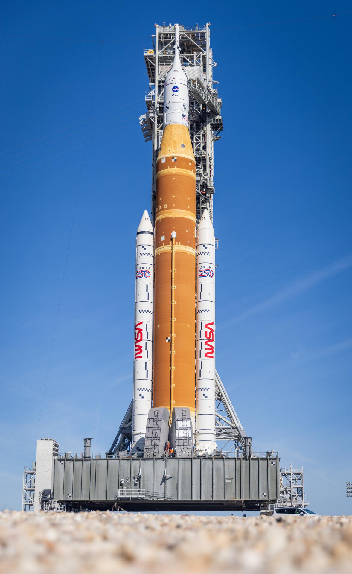
NASA’s Artemis II SLS (Space Launch System) rocket and Orion spacecraft, secured to the mobile launcher, stands vertical at Launch Complex 39B at NASA’s Kennedy Space Center in Florida on Tuesday, Jan. 20, 2026. The Artemis II test flight will take Commander Reid Wiseman, Pilot Victor Glover, and Mission Specialist Christina Koch from NASA, and Mission Specialist Jeremy Hansen from the CSA (Canadian Space Agency), on a 10-day journey no earlier than 6:24 p.m. EDT on Wednesday, April 1.
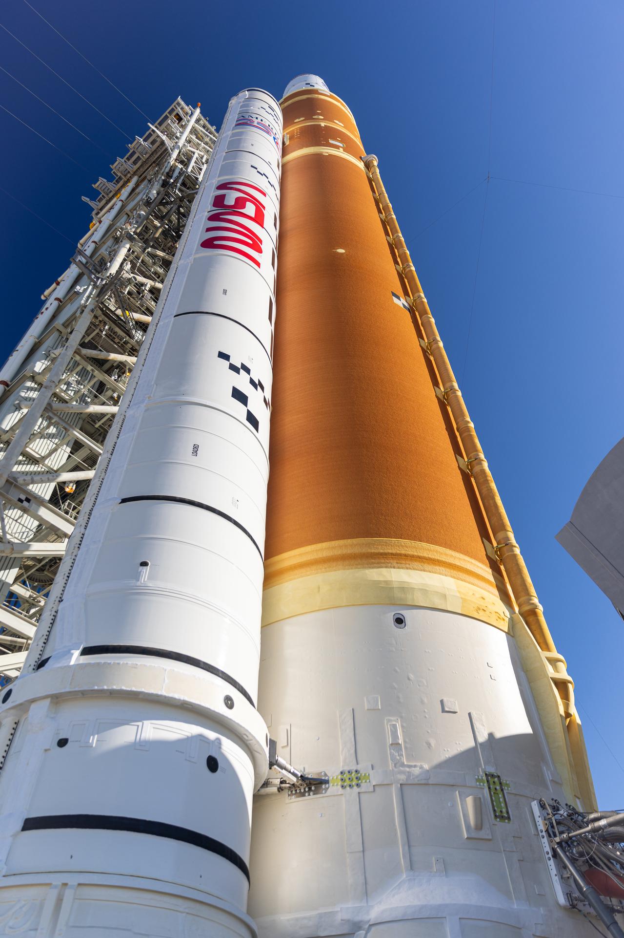
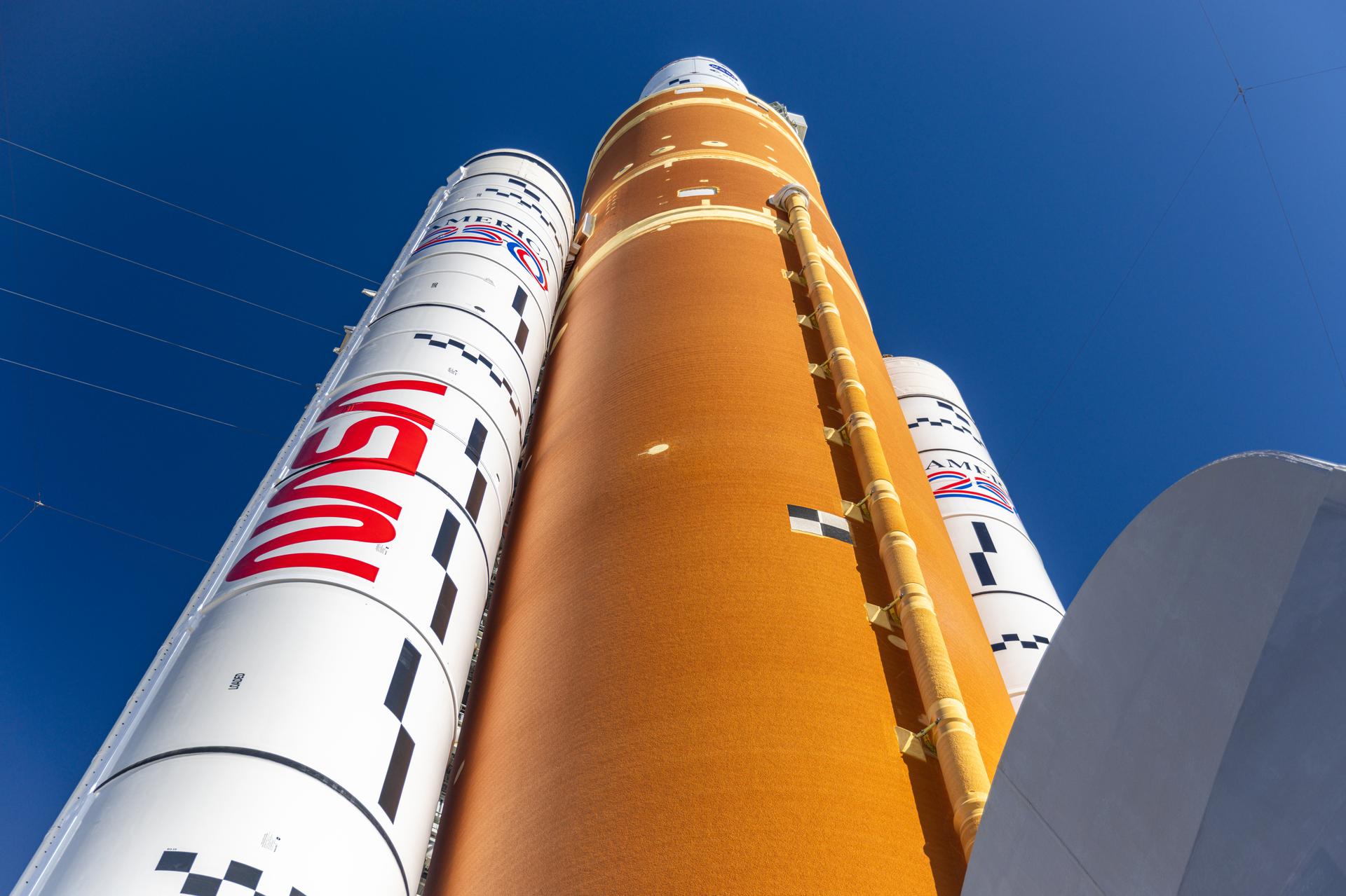
This photograph shows a closeup view of one of the solid rocket boosters attached to NASA’s Artemis II SLS (Space Launch System) rocket at Launch Complex 39B with the Vehicle Assembly Building in the background at NASA’s Kennedy Space Center in Florida on Tuesday, Jan. 20, 2026. The Artemis II test flight will take Commander Reid Wiseman, Pilot Victor Glover, and Mission Specialist Christina Koch from NASA, and Mission Specialist Jeremy Hansen from the CSA (Canadian Space Agency), on a 10-day journey no earlier than 6:24 p.m. EDT on Wednesday, April 1.
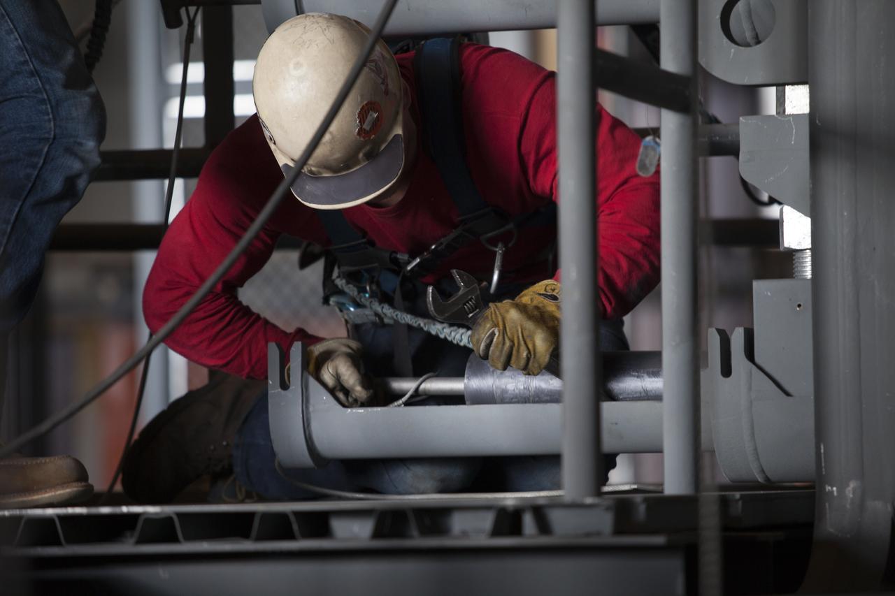
A construction worker wearing a safety harness and tethered lines turns a bolt to help secure the second half of the B-level work platforms, B north, for NASA's Space Launch System (SLS) rocket, during installation in High Bay 3 of the Vehicle Assembly Building (VAB) at NASA's Kennedy Space Center in Florida. The B platform is being installed on the north side of the high bay. The B platforms are the ninth of 10 levels of work platforms that will surround and provide access to the SLS rocket and Orion spacecraft for Exploration Mission 1. The Ground Systems Development and Operations Program is overseeing upgrades and modifications to VAB High Bay 3, including installation of the new work platforms, to prepare for NASA’s Journey to Mars.
The second half of the B-level work platforms, B north, for NASA's Space Launch System (SLS) rocket, is lowered by crane for installation on the north side of High Bay 3 in the Vehicle Assembly Building (VAB) at NASA's Kennedy Space Center in Florida. Construction workers will secure the large bolts that hold the platform in place on the north wall. The B platforms are the ninth of 10 levels of work platforms that will surround and provide access to the SLS rocket and Orion spacecraft for Exploration Mission 1. The Ground Systems Development and Operations Program is overseeing upgrades and modifications to VAB High Bay 3, including installation of the new work platforms, to prepare for NASA’s Journey to Mars.
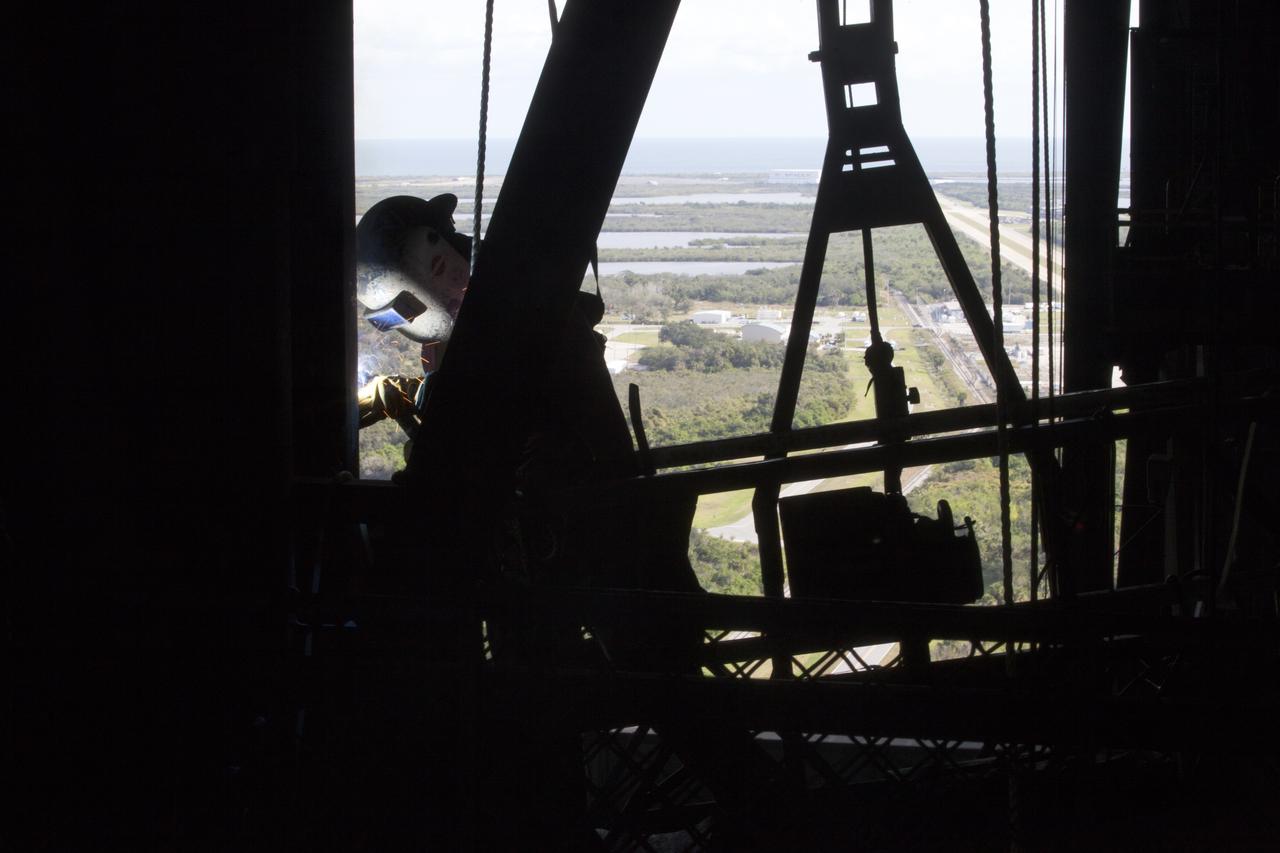
A construction worker solders a section of steel during the installation of the second half of the B-level work platforms, B north, for NASA's Space Launch System (SLS) rocket, in High Bay 3 in the Vehicle Assembly Building (VAB) at NASA's Kennedy Space Center in Florida. Construction workers will secure the large bolts that hold the platform in place on the north wall. The B platforms are the ninth of 10 levels of work platforms that will surround and provide access to the SLS rocket and Orion spacecraft for Exploration Mission 1. The Ground Systems Development and Operations Program is overseeing upgrades and modifications to VAB High Bay 3, including installation of the new work platforms, to prepare for NASA’s Journey to Mars.
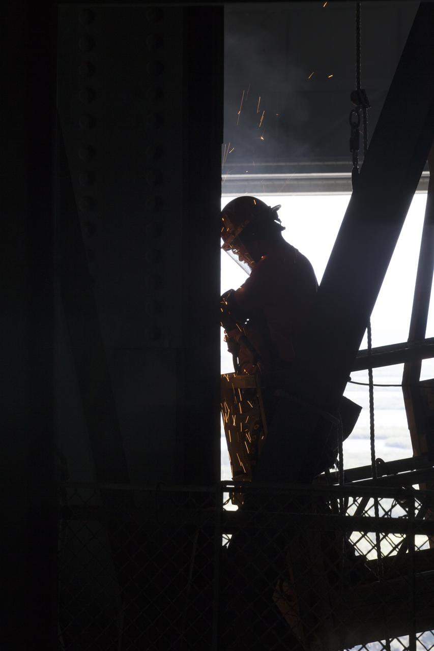
A construction worker makes adjustments to a section of steel during the installation of the second half of the B-level work platforms, B north, for NASA's Space Launch System (SLS) rocket, in High Bay 3 in the Vehicle Assembly Building (VAB) at NASA's Kennedy Space Center in Florida. Construction workers will secure the large bolts that hold the platform in place on the north wall. The B platforms are the ninth of 10 levels of work platforms that will surround and provide access to the SLS rocket and Orion spacecraft for Exploration Mission 1. The Ground Systems Development and Operations Program is overseeing upgrades and modifications to VAB High Bay 3, including installation of the new work platforms, to prepare for NASA’s Journey to Mars.
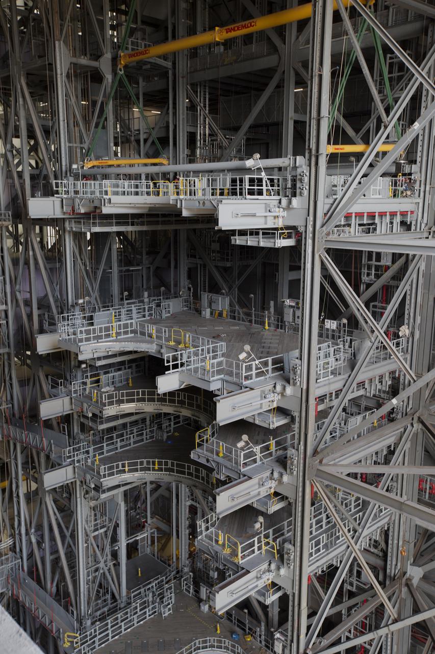
High up in the Vehicle Assembly Building (VAB) at NASA's Kennedy Space Center in Florida, the second half of the B-level work platforms, B north, for NASA's Space Launch System (SLS) rocket, has been lowered into place for installation on the north wall of High Bay 3. In view below are several levels of previously installed platforms. The B platforms are the ninth of 10 levels of work platforms that will surround and provide access to the SLS rocket and Orion spacecraft for Exploration Mission 1. The Ground Systems Development and Operations Program is overseeing upgrades and modifications to VAB High Bay 3, including installation of the new work platforms, to prepare for NASA’s Journey to Mars.

Saturn C and B Rings From the Inside Out
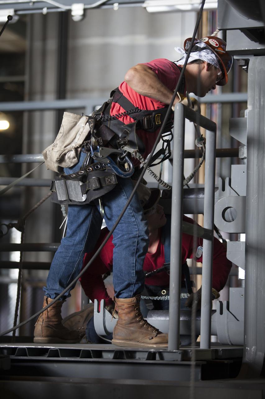
Construction workers wearing safety harnesses and tethered lines assist with the installation of the second half of the B-level work platforms, B north, for NASA’s Space Launch System (SLS) rocket, high up in the Vehicle Assembly Building (VAB) at NASA’s Kennedy Space Center in Florida. They are securing the large bolts that hold the platform securely in place on the north side of High Bay 3. The B platforms are the ninth of 10 levels of work platforms that will surround and provide access to the SLS rocket and Orion spacecraft for Exploration Mission 1. The Ground Systems Development and Operations Program is overseeing upgrades and modifications to VAB High Bay 3, including installation of the new work platforms, to prepare for NASA’s Journey to Mars.
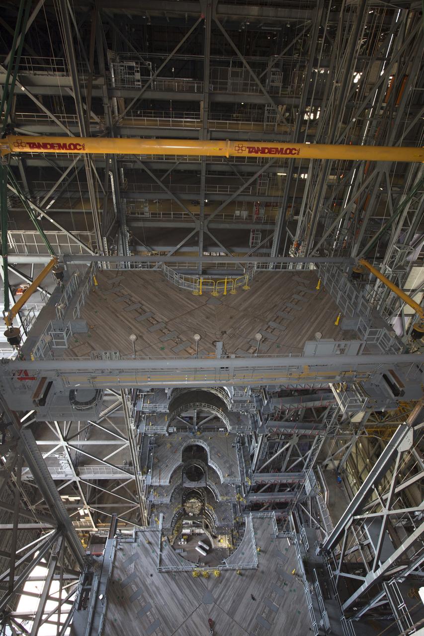
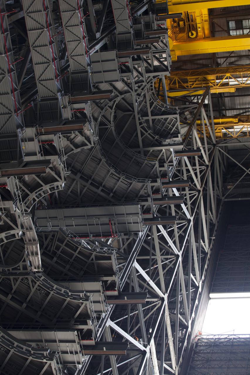
The second half of the B-level work platforms, B north, for NASA's Space Launch System (SLS) rocket, is lowered by crane for installation on the north side of High Bay 3 in the Vehicle Assembly Building (VAB) at NASA's Kennedy Space Center in Florida. Large Tandemloc bars have been attached to the platform to keep it level during lifting, lowering and installation. In view below are several levels of previously installed platforms. The B platforms are the ninth of 10 levels of work platforms that will surround and provide access to the SLS rocket and Orion spacecraft for Exploration Mission 1. The Ground Systems Development and Operations Program is overseeing upgrades and modifications to VAB High Bay 3, including installation of the new work platforms, to prepare for NASA’s Journey to Mars.
The second half of the B-level work platforms, B north, for NASA's Space Launch System (SLS) rocket, is lifted up by crane in the transfer aisle of the Vehicle Assembly Building (VAB) at NASA's Kennedy Space Center in Florida. The platform will be lowered into High Bay 3 and installed on the north side of the high bay. Construction workers will secure the large bolts that hold the platform in place on the north wall. The B platforms are the ninth of 10 levels of work platforms that will surround and provide access to the SLS rocket and Orion spacecraft for Exploration Mission 1. The Ground Systems Development and Operations Program is overseeing upgrades and modifications to VAB High Bay 3, including installation of the new work platforms, to prepare for NASA’s Journey to Mars.
The second half of the B-level work platforms, B north, for NASA's Space Launch System (SLS) rocket, is lifted up by crane in the transfer aisle of the Vehicle Assembly Building (VAB) at NASA's Kennedy Space Center in Florida. The platform will be lowered into High Bay 3 and installed on the north side of the high bay. Construction workers will secure the large bolts that hold the platform in place on the north wall. The B platforms are the ninth of 10 levels of work platforms that will surround and provide access to the SLS rocket and Orion spacecraft for Exploration Mission 1. The Ground Systems Development and Operations Program is overseeing upgrades and modifications to VAB High Bay 3, including installation of the new work platforms, to prepare for NASA’s Journey to Mars.
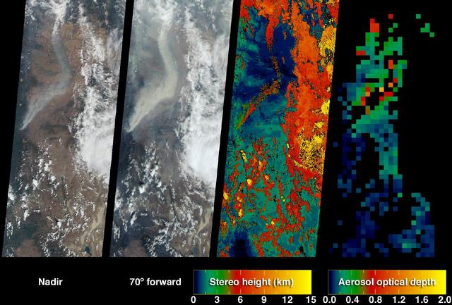
The extent, height, and amount of smoke originating from the B&B Complex Fires in central Oregon are captured in these September 4, 2003 views from NASA Terra spacecraft.

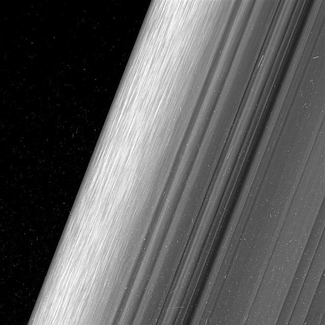
This image shows a region in Saturn's outer B ring. NASA's Cassini spacecraft viewed this area at a level of detail twice as high as it had ever been observed before. And from this view, it is clear that there are still finer details to uncover. Researchers have yet to determine what generated the rich structure seen in this view, but they hope detailed images like this will help them unravel the mystery. In order to preserve the finest details, this image has not been processed to remove the many small bright blemishes, which are created by cosmic rays and charged particle radiation near the planet. The image was taken in visible light with the Cassini spacecraft wide-angle camera on Dec. 18, 2016. The view was obtained at a distance of approximately 32,000 miles (51,000 kilometers) from the rings, and looks toward the unilluminated side of the rings. Image scale is about a quarter-mile (360 meters) per pixel. http://photojournal.jpl.nasa.gov/catalog/PIA21058

B-33 Vega Turrets. Photo are listed in the NACA Wartime report L-463, October 1942, Test of a Large Spherical Turret and a modified Turret on a Typical Bomber Fuselage by Axel T. Mattson.
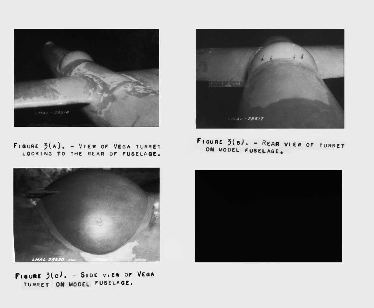
B-33 Vega Turrets. Photo are listed in the NACA Wartime report L-463, October 1942, Test of a Large Spherical Turret and a modified Turret on a Typical Bomber Fuselage by Axel T. Mattson.
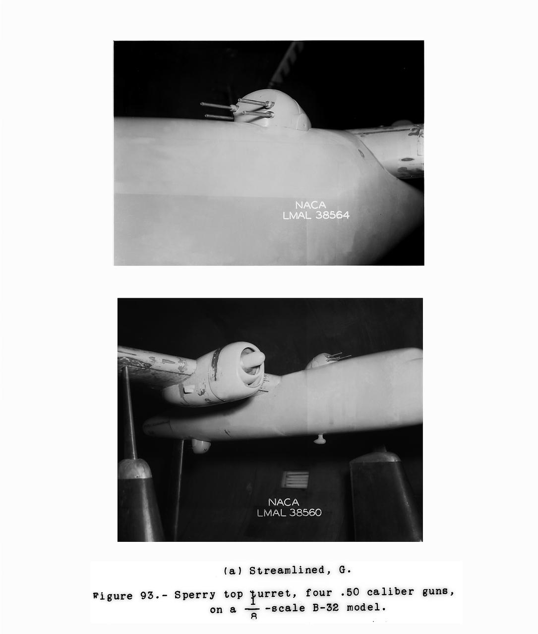
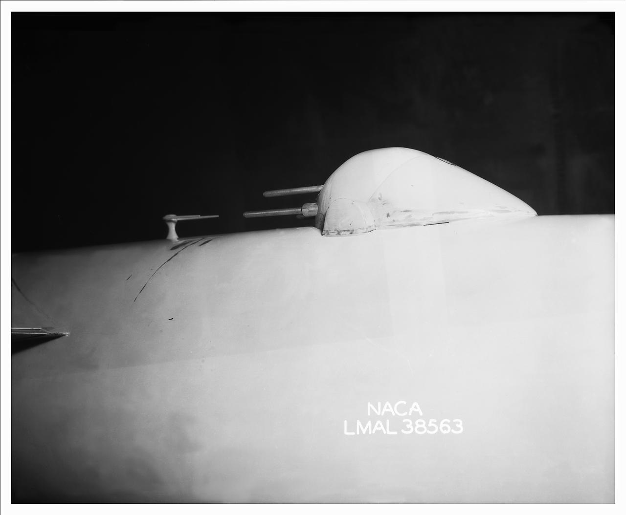
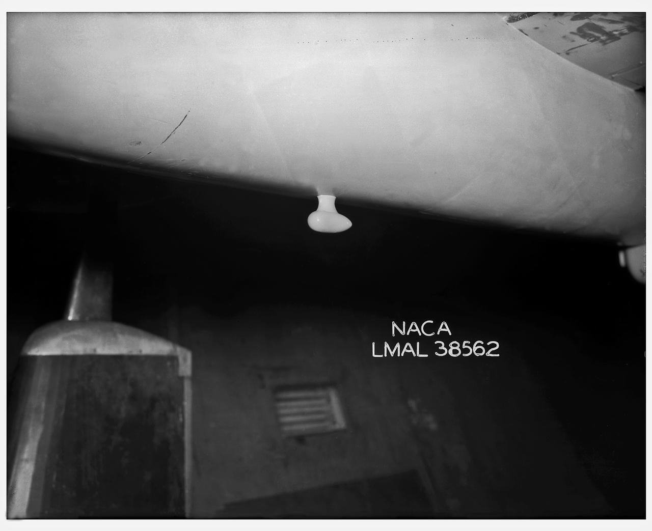
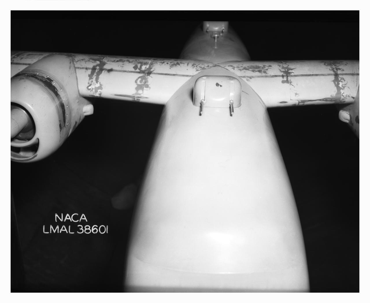
B-32 Model Close Up. Test conducted in the NACA 19 foot pressure tunnel LMAL-38560 NACA document.
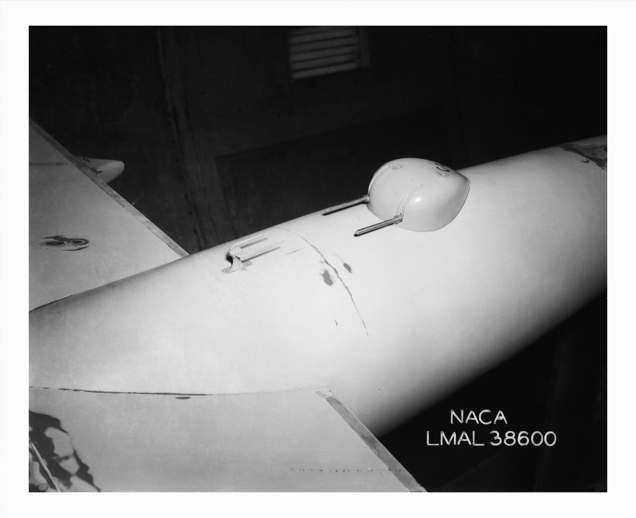
B-32 Model Close Up, Test conducted in the NACA 19 foot pressure tunnel LMAL-38560 NACA document.
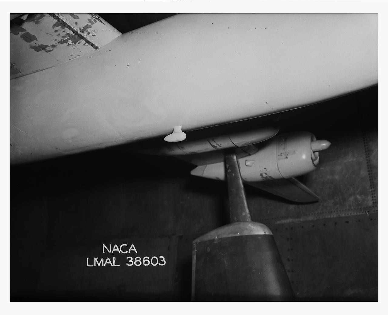
B-32 Model Close Up. Test conducted in the NACA 19 foot pressure tunnel LMAL-38560 NACA document.
B-32 Model Close Up. Test conducted in the NACA 19 foot pressure tunnel LMAL-38560 NACA document.
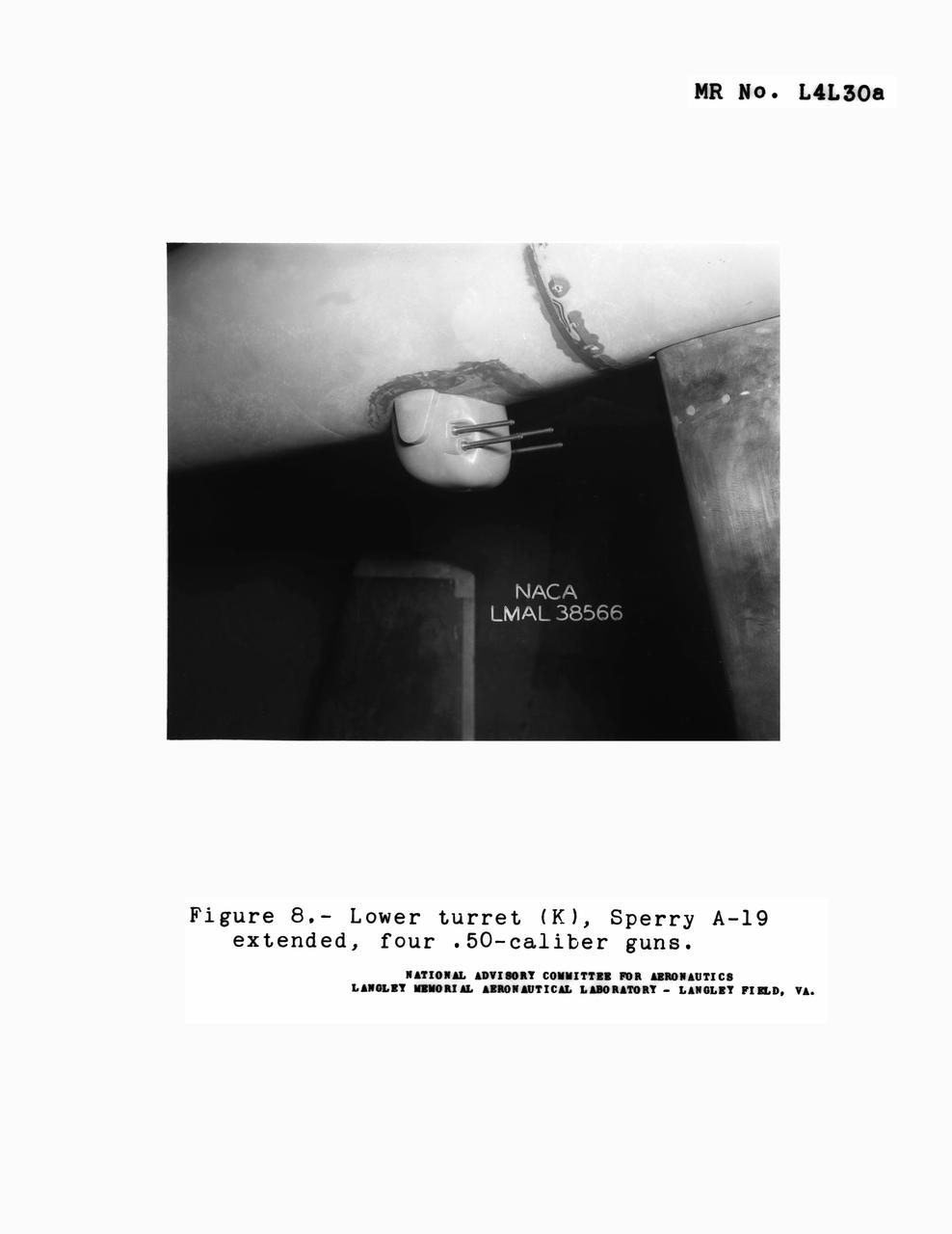
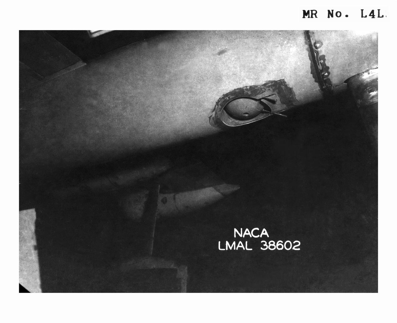
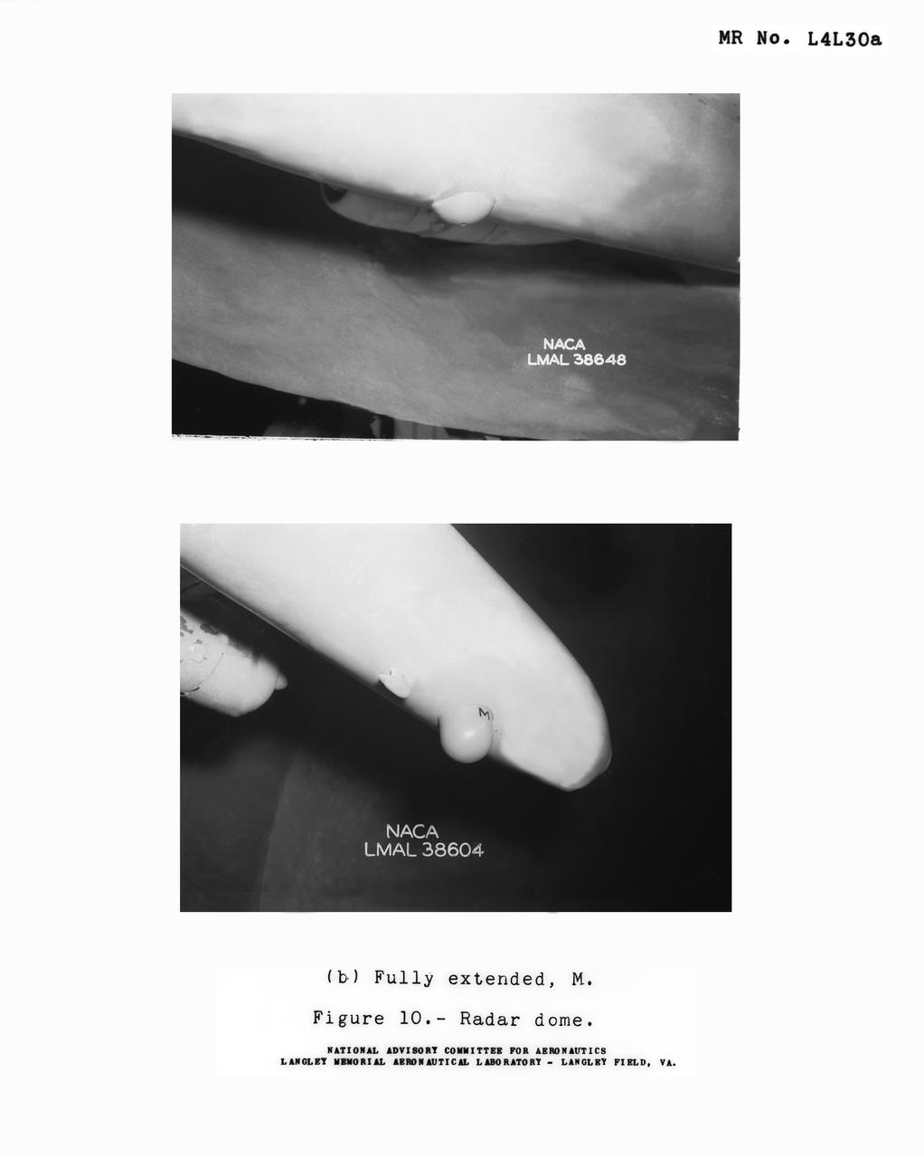
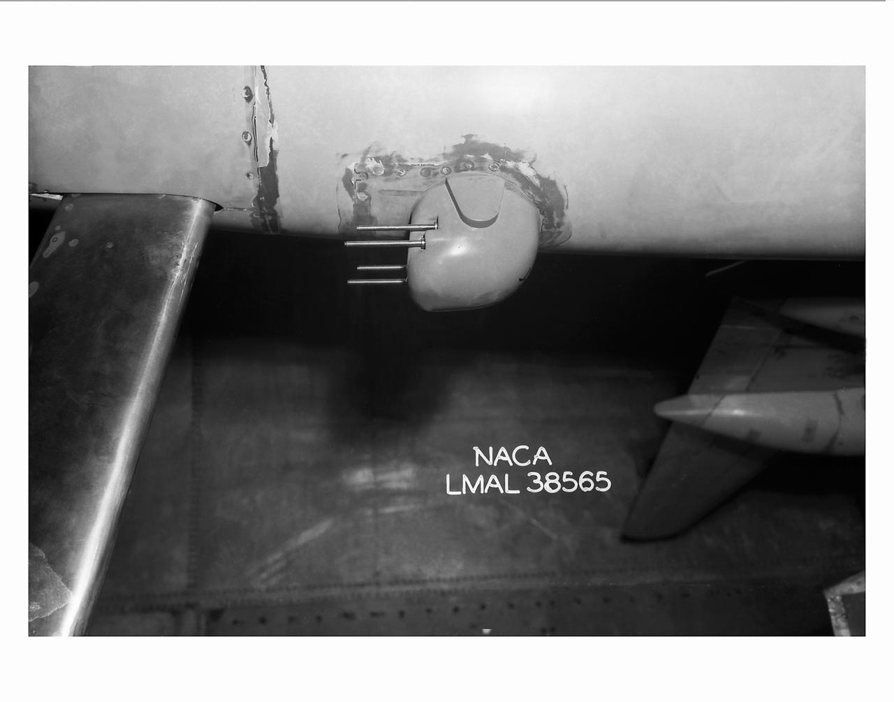
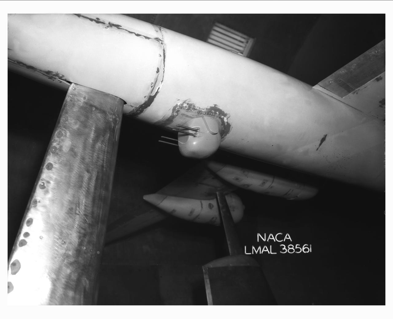
Detail Shots of B-32 Turret. Test conducted in the NACA 19 foot pressure tunnel LMAL-38560 NACA document.
Detail Shots of B-32 Turret. Test conducted in the NACA 19 foot pressure tunnel LMAL-38560 NACA document.
Detail Shots of B-32 Turret. Test conducted in the NACA 19 foot pressure tunnel LMAL-38560 NACA document.
Detail Shots of B-32 Turret. Test conducted in the NACA 19 foot pressure tunnel LMAL-38560 NACA document.
B-32 Model Close Up. Test conducted in the NACA 19 foot pressure tunnel LMAL-38560 NACA document.
Detail Shots of B-32 Turret. Test conducted in the NACA 19 foot pressure tunnel LMAL-38560 NACA document.
Detail Shots of B-32 Turret. Test conducted in the NACA 19 foot pressure tunnel LMAL-38560 NACA document.
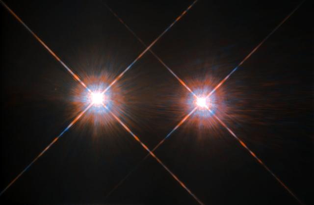
The closest star system to the Earth is the famous Alpha Centauri group. Located in the constellation of Centaurus (The Centaur), at a distance of 4.3 light-years, this system is made up of the binary formed by the stars Alpha Centauri A and Alpha Centauri B, plus the faint red dwarf Alpha Centauri C, also known as Proxima Centauri. This NASA/ESA Hubble Space Telescope has given us this stunning view of the bright Alpha Centauri A (on the left) and Alpha Centauri B (on the right), shining like huge cosmic headlamps in the dark. The image was captured by the Wide-Field and Planetary Camera 2 (WFPC2). WFPC2 was Hubble’s most used instrument for the first 13 years of the space telescope’s life, being replaced in 2009 by Wide-Field Camera 3 (WFC3) during Servicing Mission 4. This portrait of Alpha Centauri was produced by observations carried out at optical and near-infrared wavelengths. Compared to the sun, Alpha Centauri A is of the same stellar type, G2, and slightly bigger, while Alpha Centauri B, a K1-type star, is slightly smaller. They orbit a common center of gravity once every 80 years, with a minimum distance of about 11 times the distance between Earth and the sun. Because these two stars are, together with their sibling Proxima Centauri, the closest to Earth, they are among the best studied by astronomers. And they are also among the prime targets in the hunt for habitable exoplanets. Using the European Space Organization's HARPS instrument, astronomers already discovered a planet orbiting Alpha Centauri B. Then on Aug. 24, 2016, astronomers announced the intriguing discovery of a nearly Earth-sized planet in the habitable zone orbiting the star Proxima Centauri Image credit: ESA/NASA
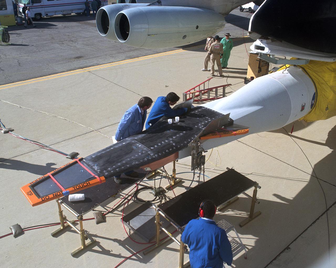
The second X-43A hypersonic research vehicle, mounted under the right wing of the B-52B launch aircraft, viewed from the B-52 cockpit. The crew is working on closing out the research vehicle, preparing it for flight.
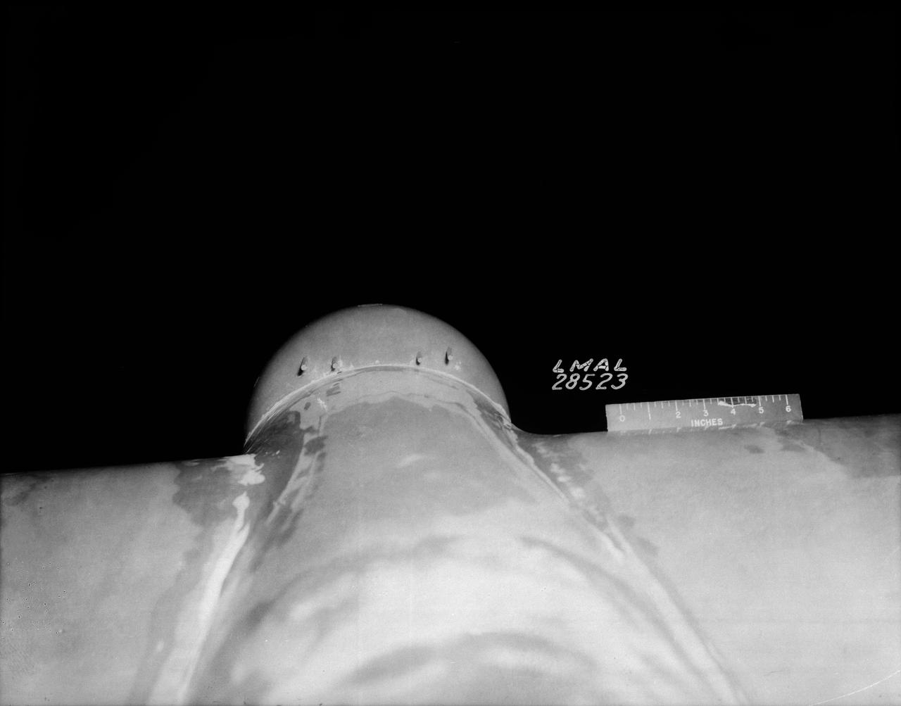
B-33 Vega Turrets. Photo are listed in the NACA Wartime report L-463, October 1942, Test of a Large Spherical Turret and a modified Turret on a Typical Bomber Fuselage by Axel T. Mattson.
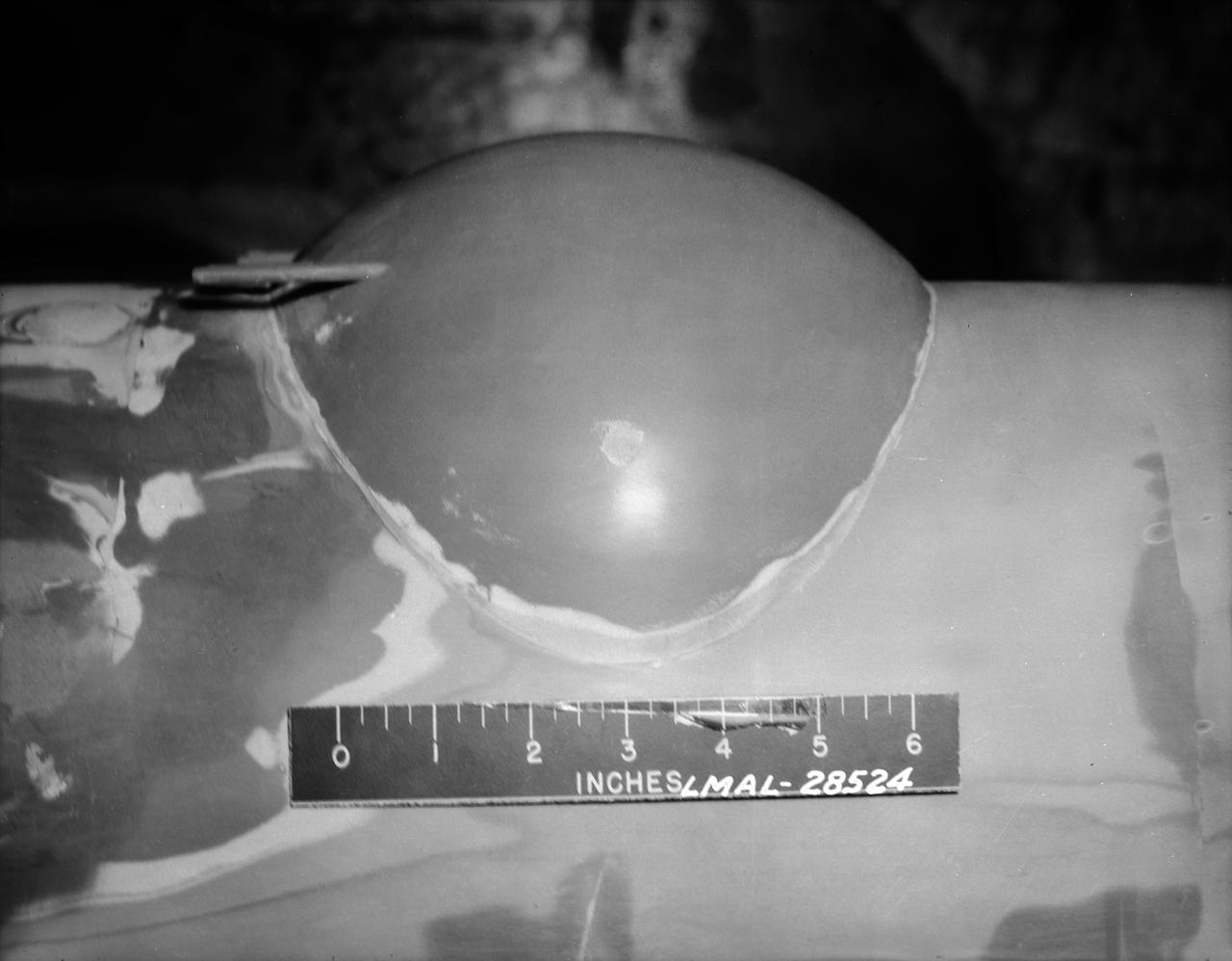
B-33 Vega Turrets. Photo are listed in the NACA Wartime report L-463, October 1942, Test of a Large Spherical Turret and a modified Turret on a Typical Bomber Fuselage by Axel T. Mattson.
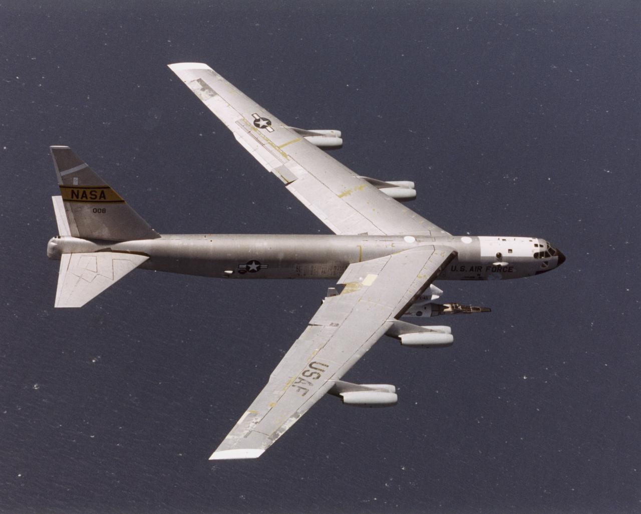
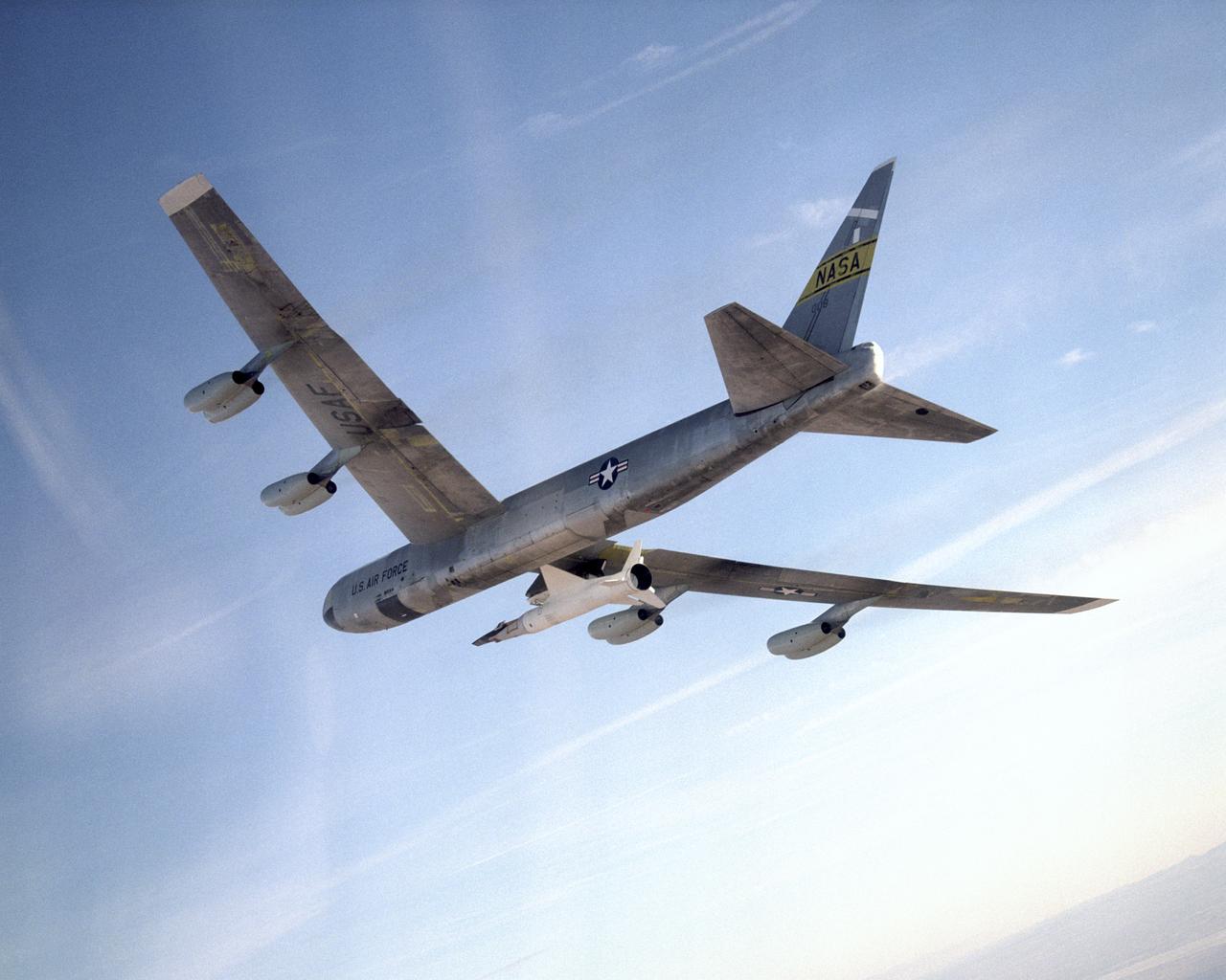
The NASA X-43A hypersonic research vehicle and its Pegasus booster rocket, mounted beneath the wing of their B-52 mothership, had a successful first captive-carry flight on April 28, 2001, Basically a dress rehearsal for a subsequent free flight, the captive-carry flight kept the X-43A-and-Pegasus combination attached to the B-52's wing pylon throughout the almost two-hour mission from NASA's Dryden Flight Research Center, Edwards, Calif., over the Pacific Missile Test Range, and back to Dryden.
The NASA X-43A hypersonic research vehicle and its Pegasus booster rocket, mounted beneath the wing of their B-52 mothership, had a successful first captive-carry flight on April 28, 2001, Basically a dress rehearsal for a subsequent free flight, the captive-carry flight kept the X-43A-and-Pegasus combination attached to the B-52's wing pylon throughout the almost two-hour mission from NASA's Dryden Flight Research Center, Edwards, Calif., over the Pacific Missile Test Range, and back to Dryden.
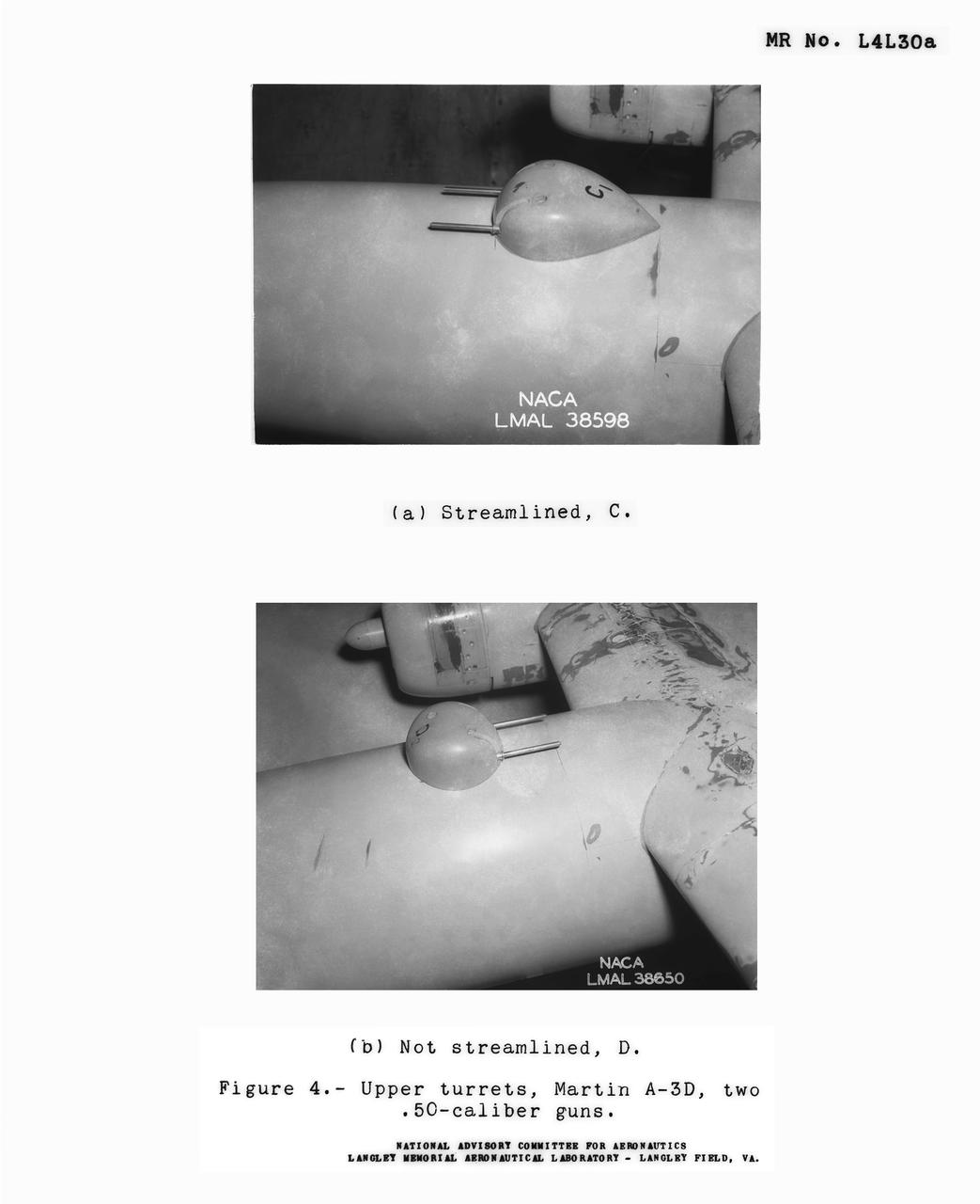
Detail Shots of B-32 Turret Figure 4. Upper turrets, Martin A-3D, Two .50 Caliber guns. Test conducted in the NACA 19 foot pressure tunnel LMAL-38560 NACA document.
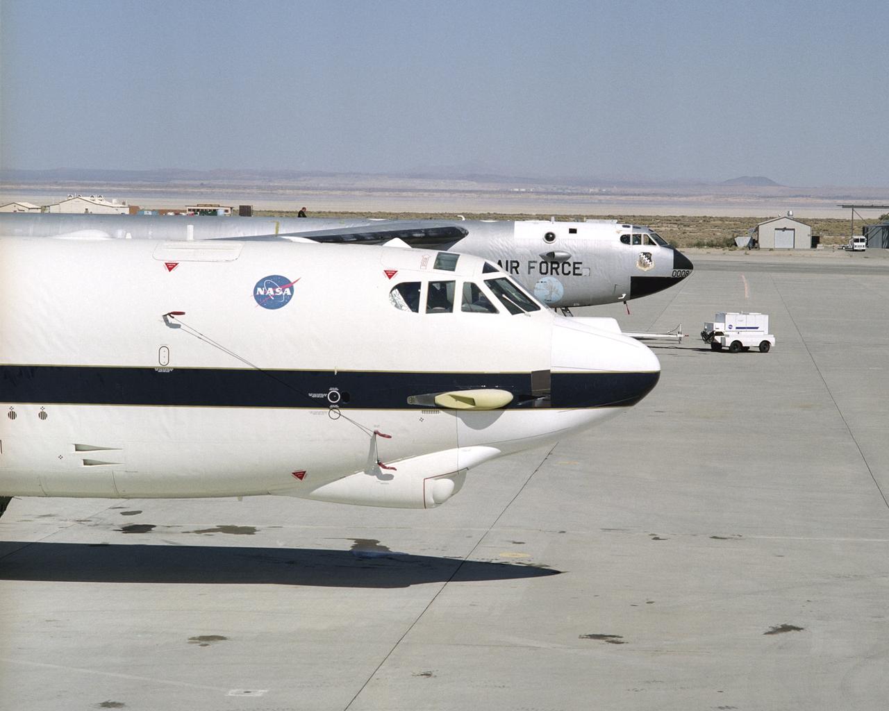
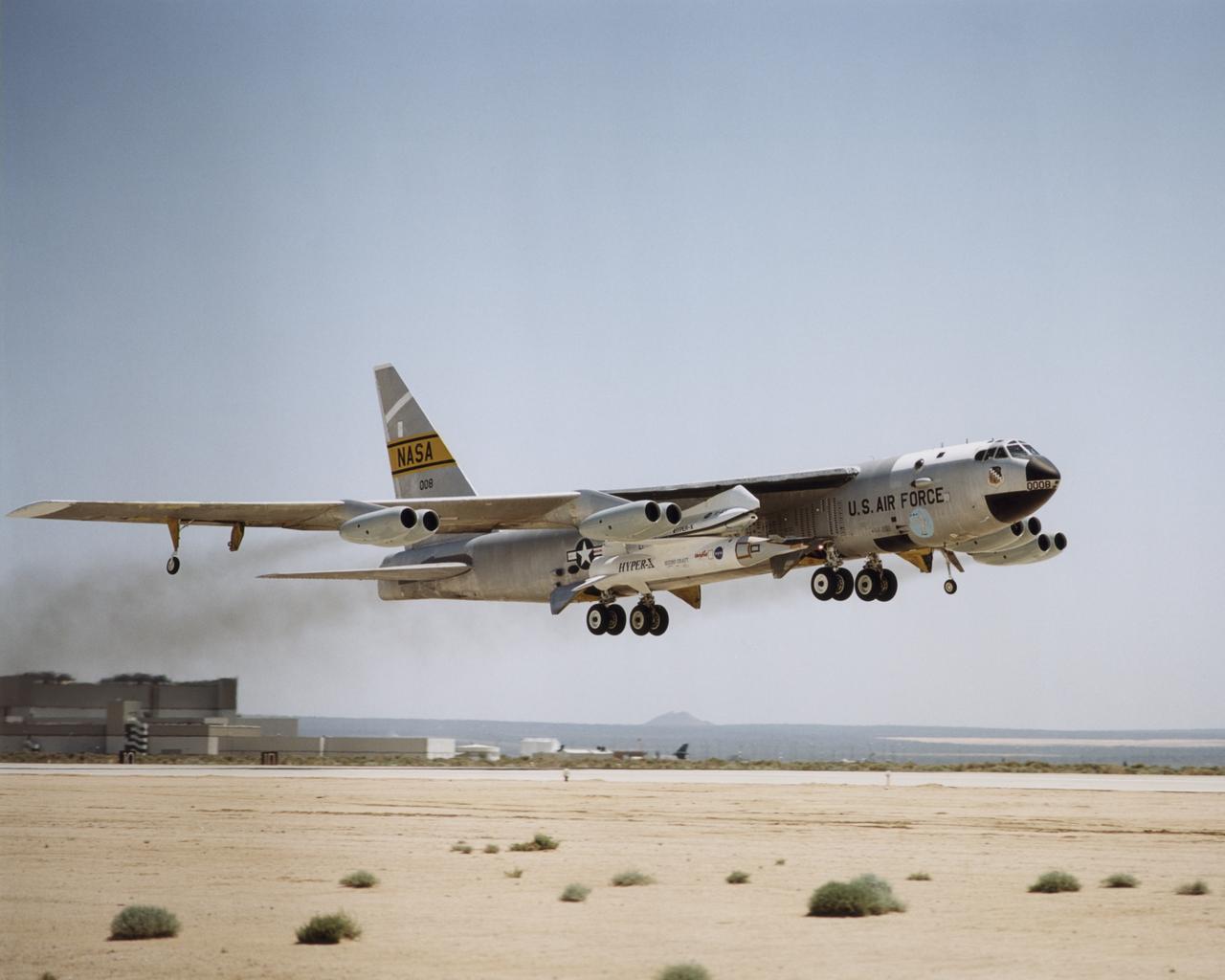
NASA's new B-52H mother ship at the ready, with renowned NASA B-52B 008 poised beside.

The shadow of the moon Epimetheus stretches across the B ring in this image taken by Cassini as Saturn approaches its 2009 equinox.
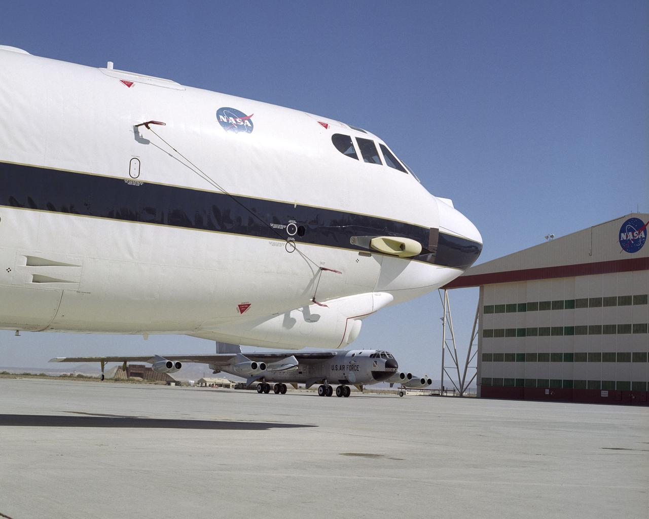
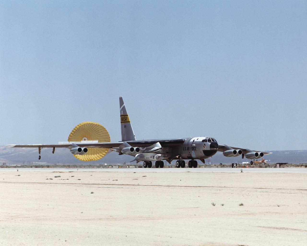
Ready to go, NASA's new B-52H mother ship waits as NASA B-52B 008 taxis back from flight.
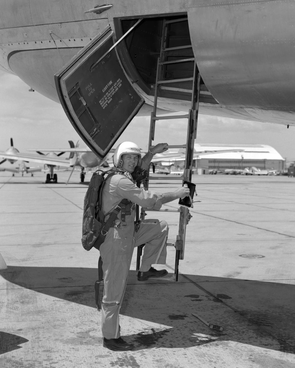
From December 10, 1966, until his retirement on February 27, 1976, Stanley P. Butchart served as Chief (later, Director) of Flight Operations at NASA's Flight Research Center (renamed on March 26, 1976, the Hugh L. Dryden Flight Research Center). Initially, his responsibilities in this position included the Research Pilots Branch, a Maintenance and Manufacturing Branch, and an Operations Engineering Branch, the last of which not only included propulsion and electrical/electronic sections but project engineers for the X-15 and lifting bodies. During his tenure, however, the responsibilities of his directorate came to include not only Flight Test Engineering Support but Flight Systems and Loads laboratories. Before becoming Chief of Flight Operations, Butchart had served since June of 1966 as head of the Research Pilots Branch (Chief Pilot) and then as acting chief of Flight Operations. He had joined the Center (then known as the National Advisory Committee for Aeronautics' High-Speed Flight Research Station) as a research pilot on May 10, 1951. During his career as a research pilot, he flew a great variety of research and air-launch aircraft including the D-558-I, D-558-II, B-29 (plus its Navy version, the P2B), X-4, X-5, KC-135, CV-880, CV-990, B-47, B-52, B-747, F-100A, F-101, F-102, F-104, PA-30 Twin Comanche, JetStar, F-111, R4D, B-720, and B-47. Although previously a single-engine pilot, he became the Center's principal multi-engine pilot during a period of air-launches in which the pilot of the air-launch aircraft (B-29 or P2B) basically directed the operations. It was he who called for the chase planes before each drop, directed the positioning of fire rescue vehicles, and released the experimental aircraft after ensuring that all was ready for the drop. As pilot of the B-29 and P2B, Butchart launched the X-1A once, the X-1B 13 times, the X-1E 22 times, and the D-558-II 102 times. In addition, he towed the M2-F1 lightweight lifting body 14 times behind an R4
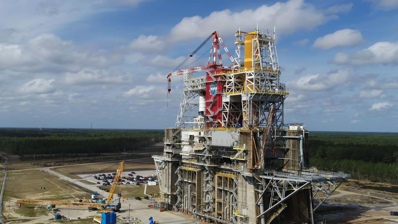
A NASA drone photo offers a bird’s-eye view of the B-2 Test Stand at NASA’s Stennis Space Center with the first flight core stage for NASA’s new Space Launch System (SLS) installed for Green Run testing. The SLS core stage is undergoing a series of tests on its integrated systems prior to its use on the Artemis I mission. NASA is building SLS to return humans, including the first woman, to the Moon as part of the Artemis program and to prepare for eventual missions to Mars. The Green Run series at Stennis culminates with a hot fire of the core stage’s four RS-25 engines, just as during an actual launch.
A NASA drone photo offers a bird’s-eye view of the B-2 Test Stand at NASA’s Stennis Space Center with the first flight core stage for NASA’s new Space Launch System (SLS) installed for Green Run testing. The SLS core stage is undergoing a series of tests on its integrated systems prior to its use on the Artemis I mission. NASA is building SLS to return humans, including the first woman, to the Moon as part of the Artemis program and to prepare for eventual missions to Mars. The Green Run series at Stennis culminates with a hot fire of the core stage’s four RS-25 engines, just as during an actual launch.
A NASA drone photo offers a bird’s-eye view of the B-2 Test Stand at NASA’s Stennis Space Center with the first flight core stage for NASA’s new Space Launch System (SLS) installed for Green Run testing. The SLS core stage is undergoing a series of tests on its integrated systems prior to its use on the Artemis I mission. NASA is building SLS to return humans, including the first woman, to the Moon as part of the Artemis program and to prepare for eventual missions to Mars. The Green Run series at Stennis culminates with a hot fire of the core stage’s four RS-25 engines, just as during an actual launch.
A NASA drone photo offers a bird’s-eye view of the B-2 Test Stand at NASA’s Stennis Space Center with the first flight core stage for NASA’s new Space Launch System (SLS) installed for Green Run testing. The SLS core stage is undergoing a series of tests on its integrated systems prior to its use on the Artemis I mission. NASA is building SLS to return humans, including the first woman, to the Moon as part of the Artemis program and to prepare for eventual missions to Mars. The Green Run series at Stennis culminates with a hot fire of the core stage’s four RS-25 engines, just as during an actual launch.
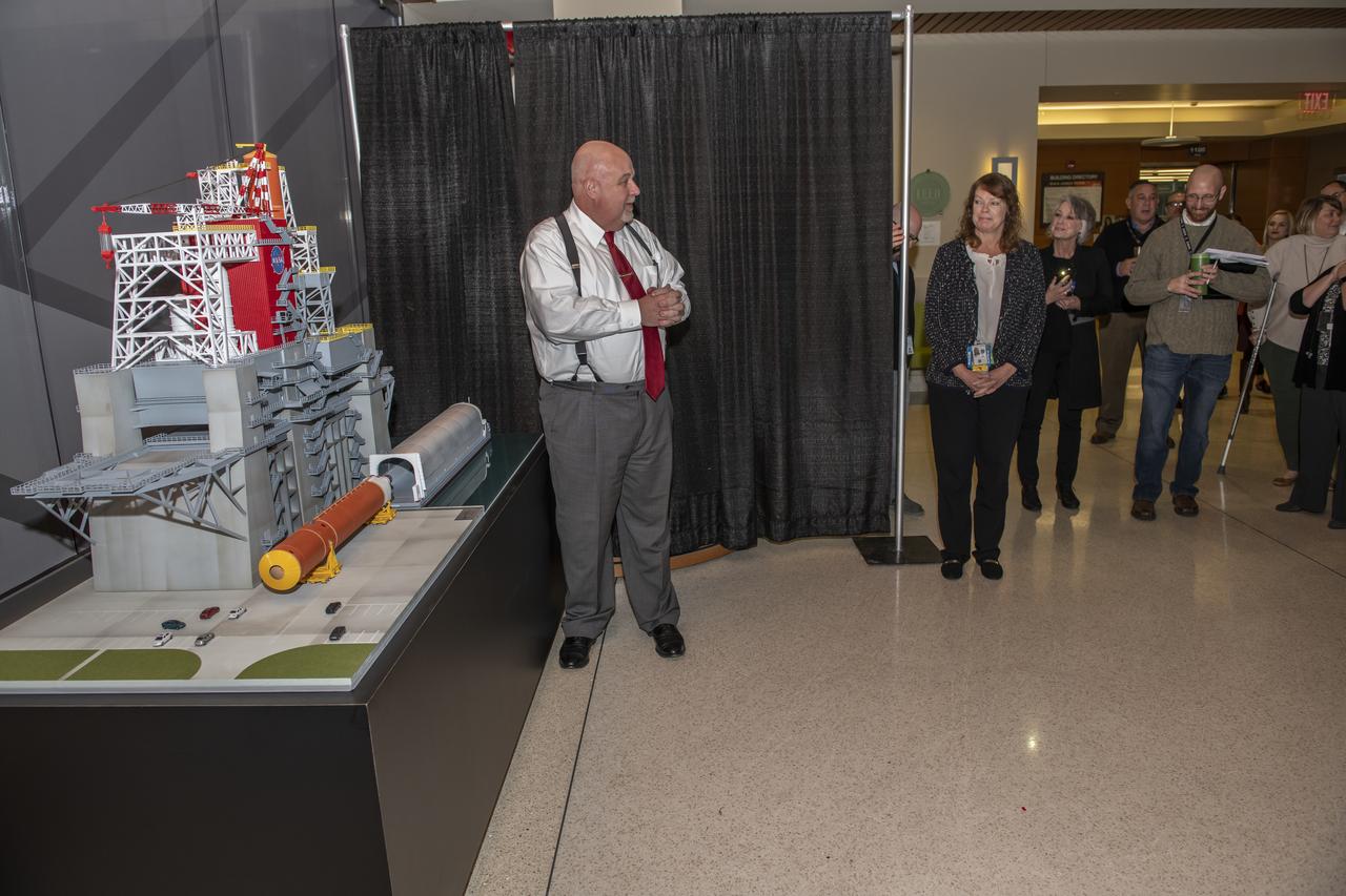
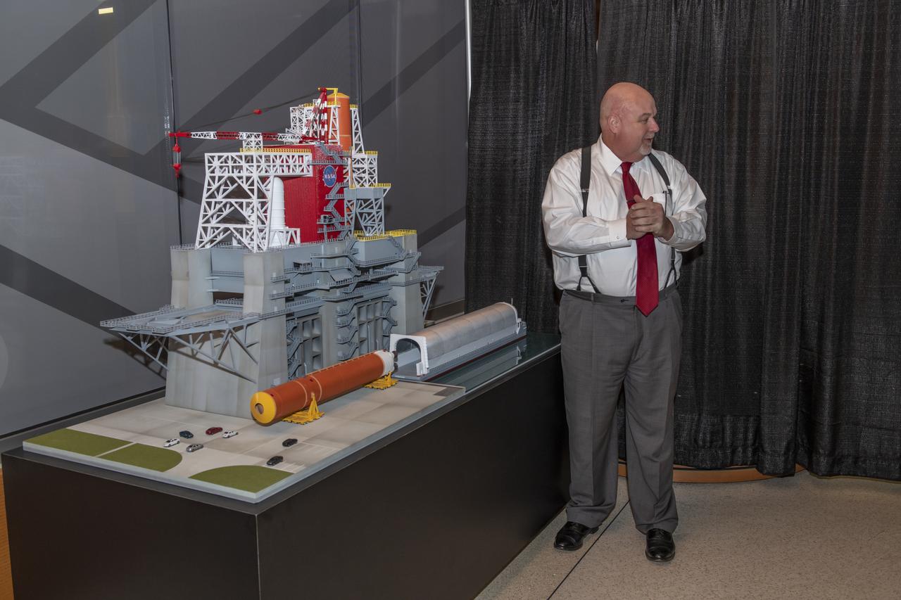
The unveiling of the B-2 Test Stand model for the SLS management team and employees in building 4220. Taking part was John Honeycutt and Julie Bassler.
The unveiling of the B-2 Test Stand model for the SLS management team and employees in building 4220. Taking part was John Honeycutt and Julie Bassler.
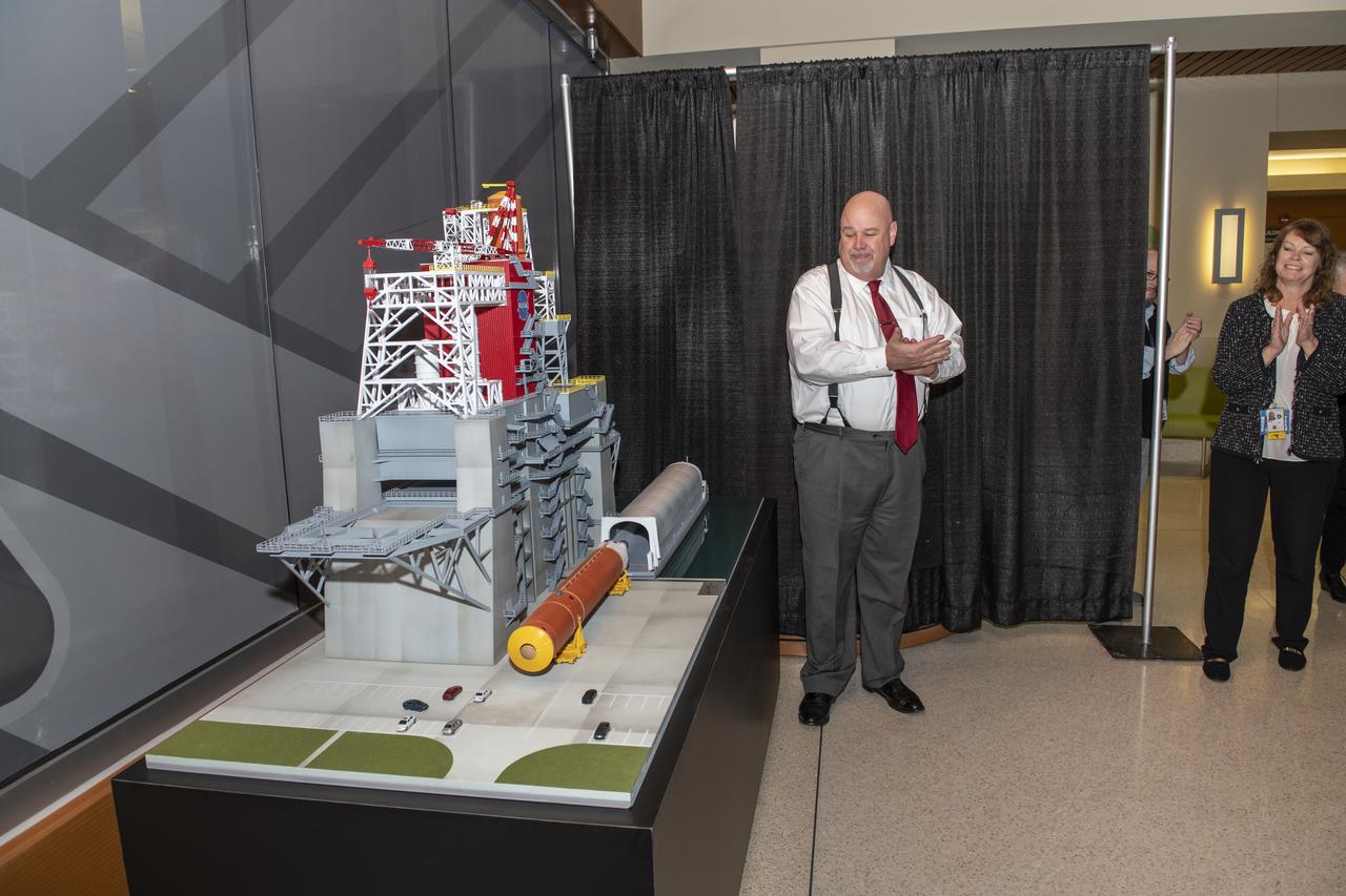
The unveiling of the B-2 Test Stand model for the SLS management team and employees in building 4220. Taking part was John Honeycutt and Julie Bassler.
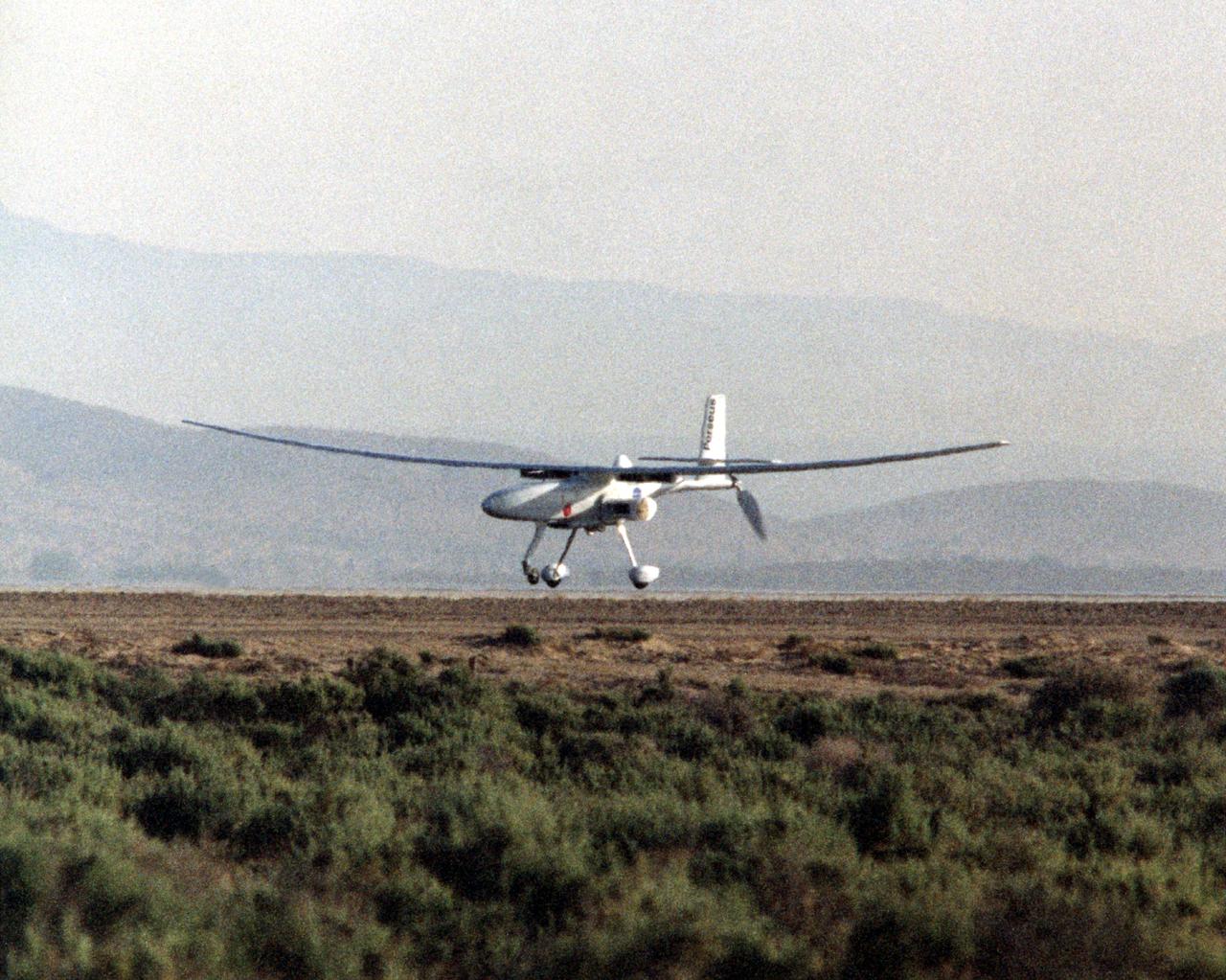
The Perseus B remotely piloted aircraft nears touchdown at Edwards Air Force Base, Calif. at the conclusion of a development flight at NASA's Dryden Flight Research Center. The Perseus B is the latest of three versions of the Perseus design developed by Aurora Flight Sciences under NASA's Environmental Research Aircraft and Sensor Technology (ERAST) program.
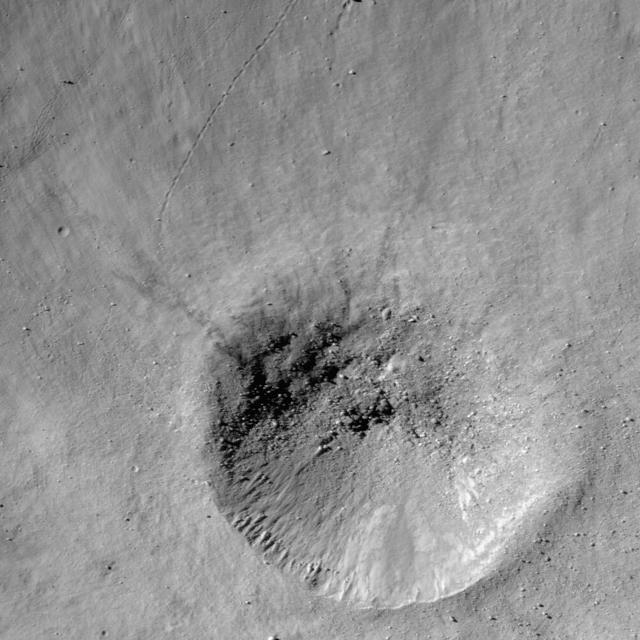
NASA Lunar Reconnaissance Orbiter takes a look at a fresh crater on the southwest rim of Metius B crater.
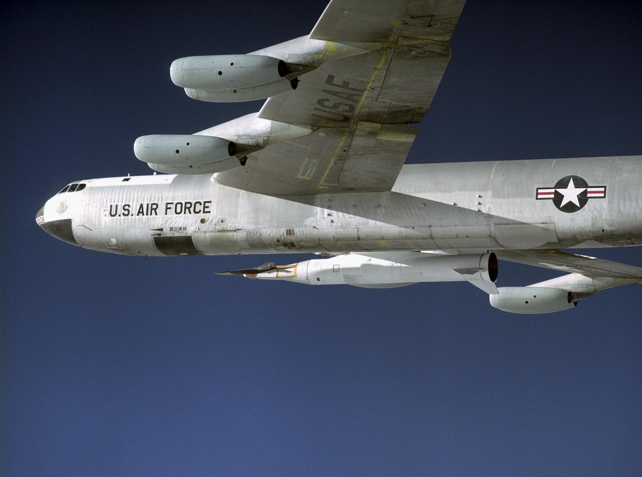
The NASA X-43A hypersonic research vehicle and its Pegasus booster rocket, mounted beneath the wing of their B-52 mothership, had a successful first captive-carry flight on April 28, 2001, Basically a dress rehearsal for a subsequent free flight, the captive-carry flight kept the X-43A-and-Pegasus combination attached to the B-52's wing pylon throughout the almost two-hour mission from NASA's Dryden Flight Research Center, Edwards, Calif., over the Pacific Missile Test Range, and back to Dryden.

Two images of Saturn A and B ring showcase the opposition effect, a brightness surge that is visible on Saturn rings when the Sun is directly behind the spacecraft

Final preparations are underway for NASA’s B-52B to carry the Pegasus booster rocket and the hypersonic X-43A aircraft during a flight test. A dry run, known as a captive carry mission, was conducted to monitor the research hardware in flight for any challenges. The January 2004 X-43A flight was based at NASA’s Armstrong Flight Research Center in Edwards, California.
The NASA X-43A hypersonic research vehicle and its Pegasus booster rocket, mounted beneath the wing of their B-52 mothership, had a successful first captive-carry flight on April 28, 2001, Basically a dress rehearsal for a subsequent free flight, the captive-carry flight kept the X-43A-and-Pegasus combination attached to the B-52's wing pylon throughout the almost two-hour mission from NASA's Dryden Flight Research Center, Edwards, Calif., over the Pacific Missile Test Range, and back to Dryden.
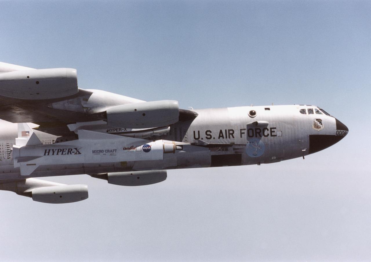
NASA's historic B-52 mother ship carried the X-43A and its Pegasus booster rocket on a captive carry flight from Edwards Air Force Base Jan. 26, 2004. The X-43A and its booster remained mated to the B-52 throughout the two-hour flight, intended to check its readiness for launch. The hydrogen-fueled aircraft is autonomous and has a wingspan of approximately 5 feet, measures 12 feet long and weighs about 2,800 pounds.
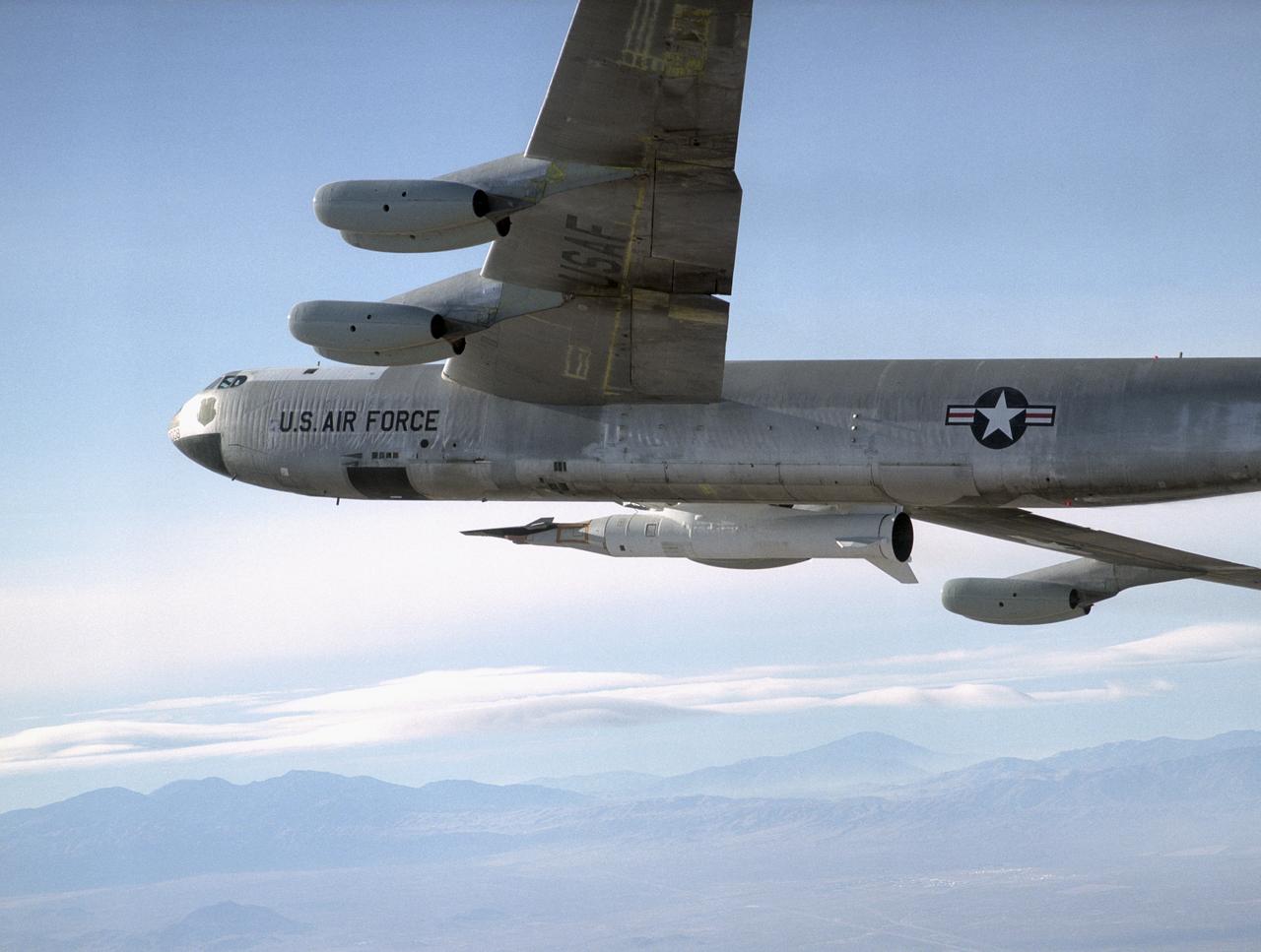
NASA's historic B-52 mother ship carried the X-43A and its Pegasus booster rocket on a captive carry flight from Edwards Air Force Base Jan. 26, 2004. The X-43A and its booster remained mated to the B-52 throughout the two-hour flight, intended to check its readiness for launch. The hydrogen-fueled aircraft is autonomous and has a wingspan of approximately 5 feet, measures 12 feet long and weighs about 2,800 pounds.
NASA's historic B-52 mother ship carried the X-43A and its Pegasus booster rocket on a captive carry flight from Edwards Air Force Base Jan. 26, 2004. The X-43A and its booster remained mated to the B-52 throughout the two-hour flight, intended to check its readiness for launch. The hydrogen-fueled aircraft is autonomous and has a wingspan of approximately 5 feet, measures 12 feet long and weighs about 2,800 pounds.
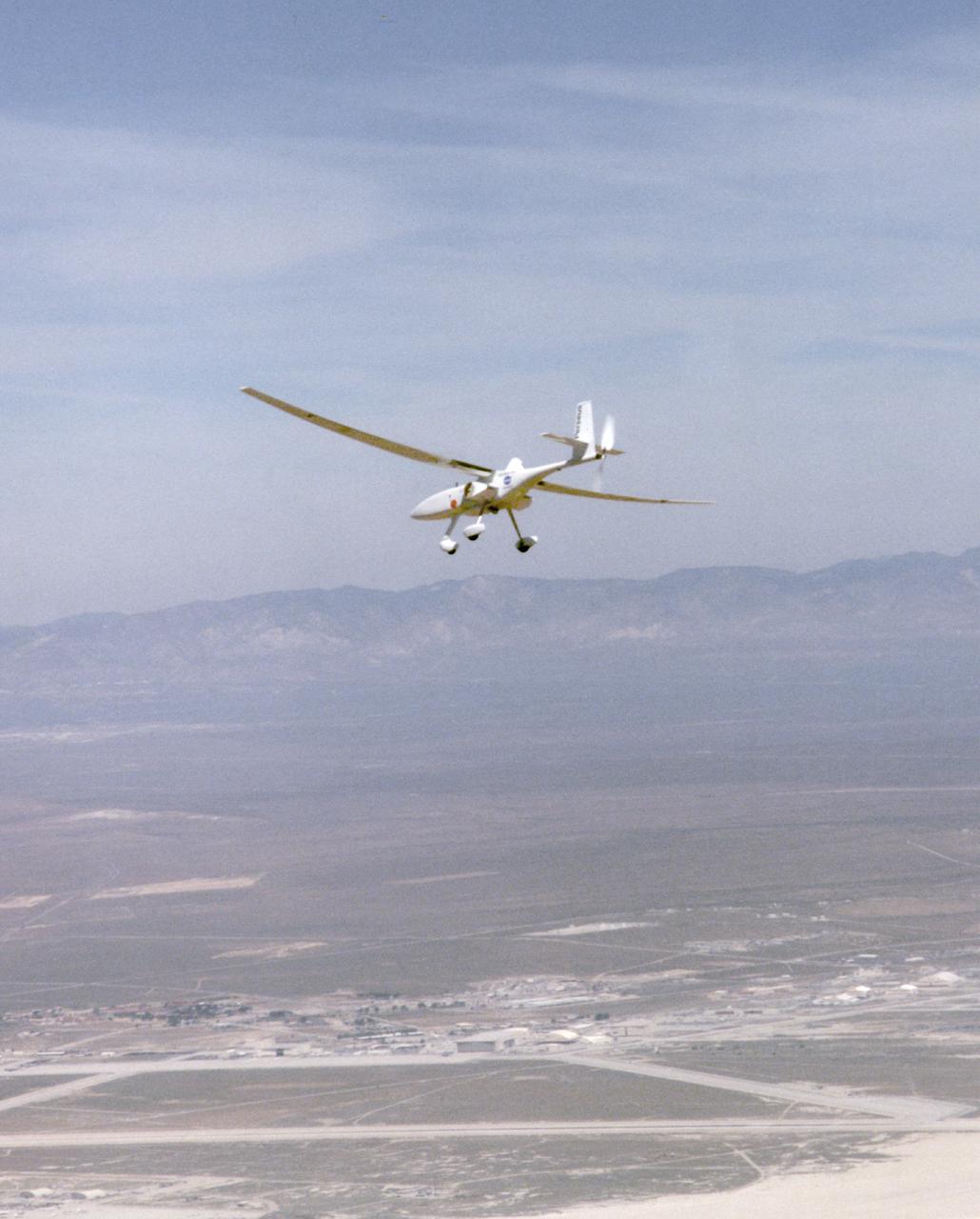
A long, slender wing and a pusher propeller at the rear characterize the Perseus B remotely-piloted research aircraft, seen here during a test flight in April1998.
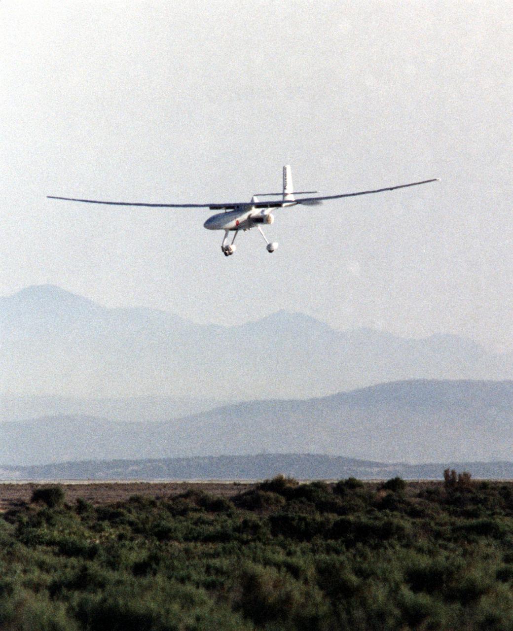
The Perseus B remotely piloted aircraft approaches the runway at Edwards Air Force Base, Calif. at the conclusion of a development flight at NASA's Dryden flight Research Center in April 1998. The Perseus B is the latest of three versions of the Perseus design developed by Aurora Flight Sciences under NASA's Environmental Research Aircraft and Sensor Technology (ERAST) program.
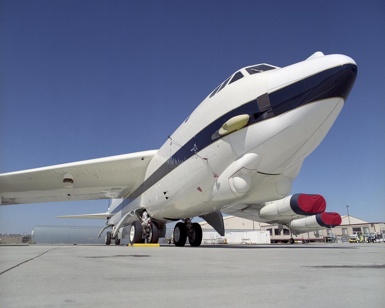
NASA's new B-52H is seen here on the ramp at the Dryden Flight Research Center, Edwards, California.