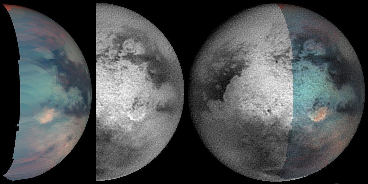
Titan Odd Spot Baffles Scientists
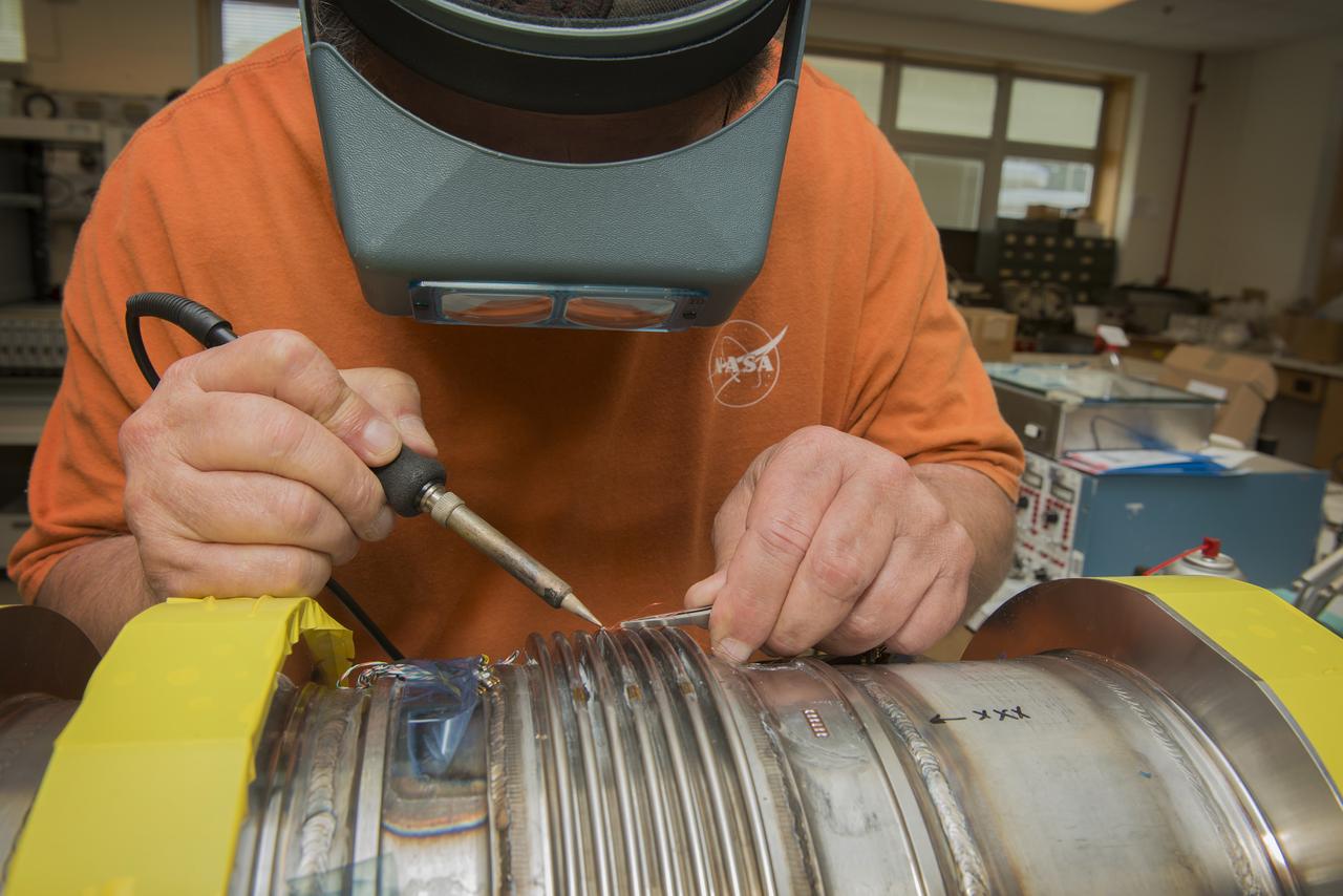
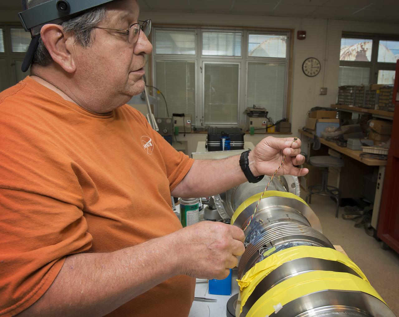
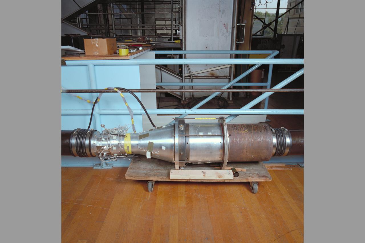
JOE MIRANDY, ET20, PREPARES SENSORS ON THE POGO Z- BAFFLE AND BELLOWS PRIOR TO FLOW TESTING. THE SENSORS WILL MEASURE VIBRATION AS FUEL FLOWS THROUGH THE TUBE AND BAFFLE.
JOE MIRANDY, ET20, PREPARES SENSORS ON THE POGO Z- BAFFLE AND BELLOWS PRIOR TO FLOW TESTING. THE SENSORS WILL MEASURE VIBRATION AS FUEL FLOWS THROUGH THE TUBE AND BAFFLE.
JOE MIRANDY, ET20, PREPARES SENSORS ON THE POGO Z- BAFFLE AND BELLOWS PRIOR TO FLOW TESTING. THE SENSORS WILL MEASURE VIBRATION AS FUEL FLOWS THROUGH THE TUBE AND BAFFLE.

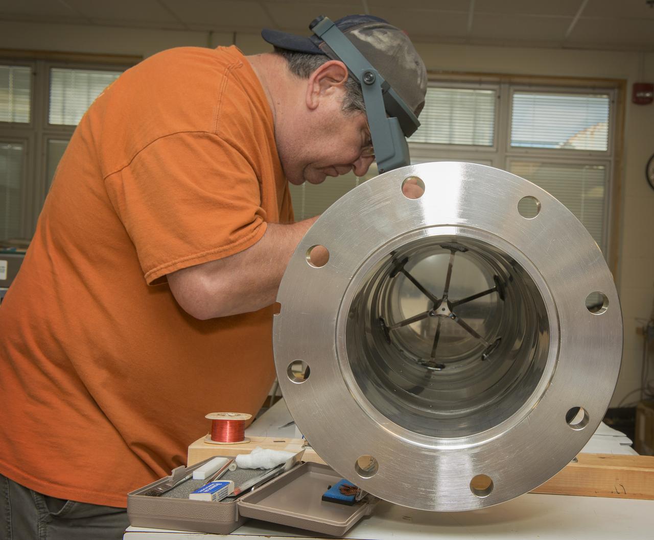
Commercial Crew Program (CCP) SpaceX Merlin Engine Gas Generator (GG) Baffle Assessment, Mr. Brian Richardson (background), and Mr. Chad Eberhart (foreground)
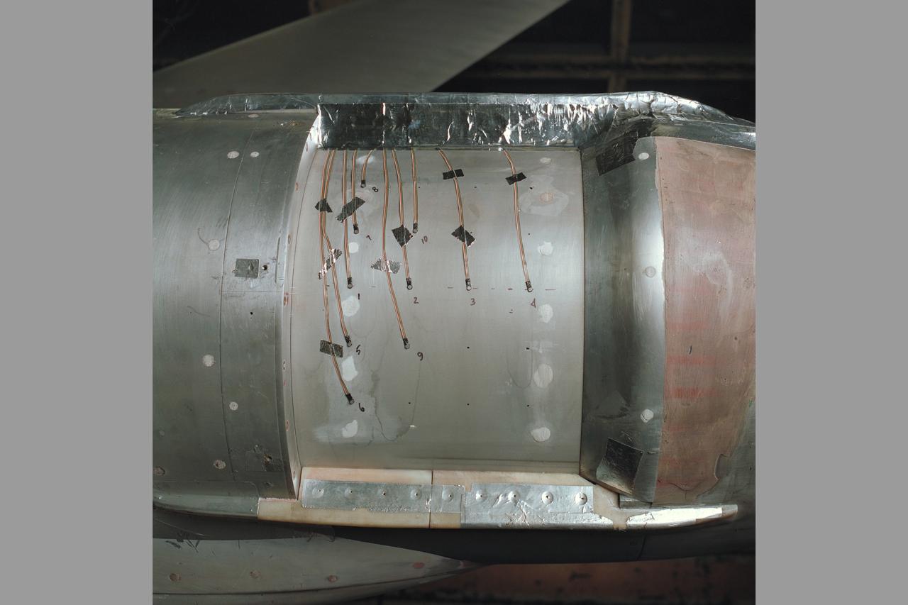
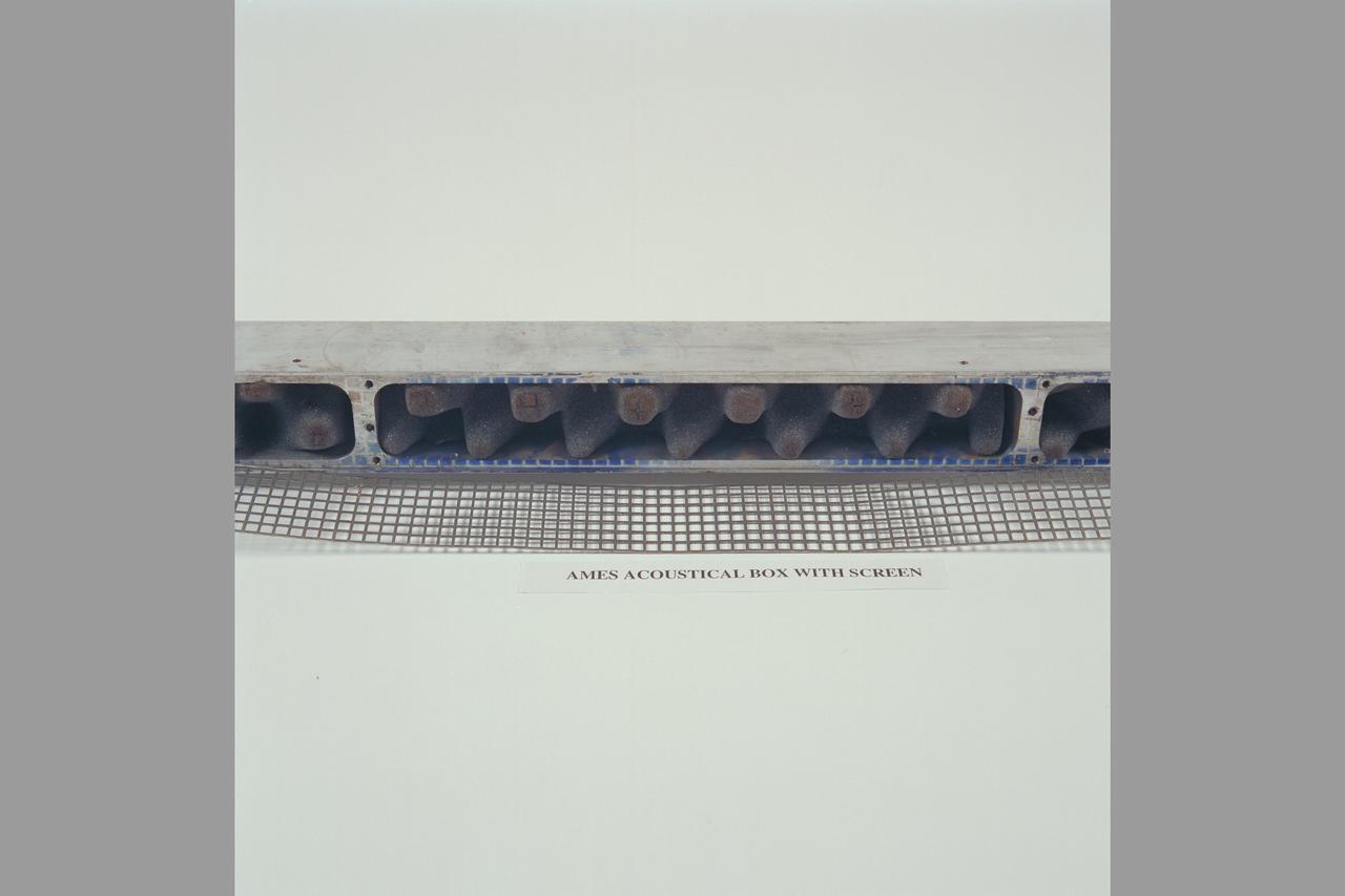
Slot Baffle III test (SOFIA) program 14ft w.t. Test-227-2-14 Telescope cover
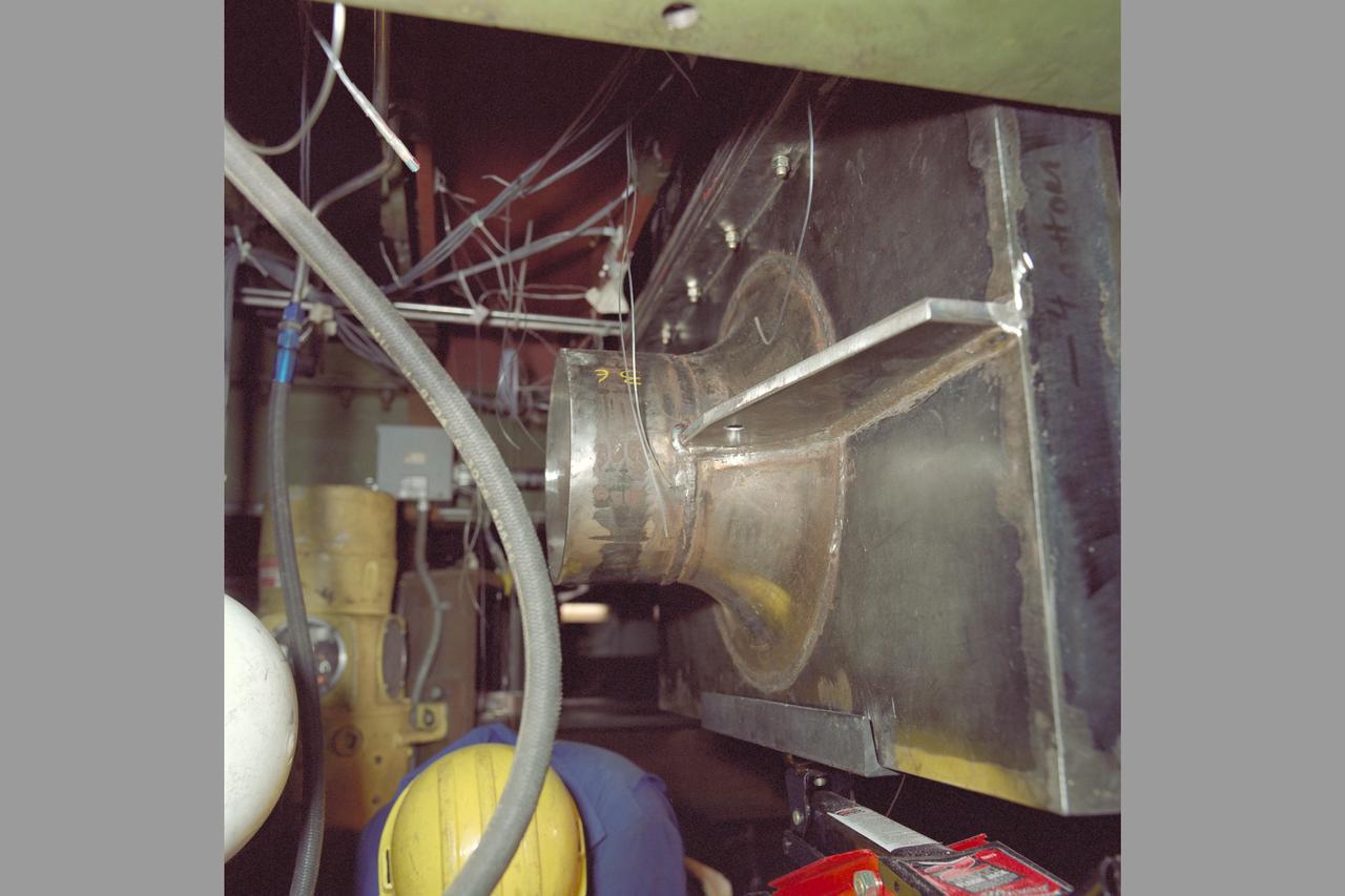
Slot Baffle III test (SOFIA) program 14ft w.t. Test-227-2-14 installation 6' calibrated Mass Flow Plug
Slot Baffle III test (SOFIA) program 14ft w.t. Test-227-2-14 installation 6' calibrated Mass Flow Plug
Slot Baffle III test (SOFIA) program 14ft w.t. Test-227-2-14 installation 6' calibrated Mass Flow Plug
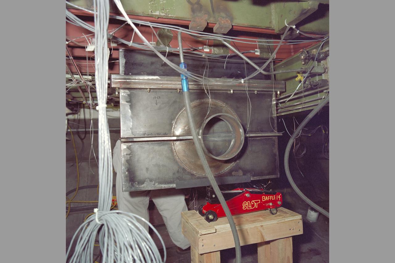
Slot Baffle III test (SOFIA) program 14ft w.t. Test-227-2-14 installation 6' calibrated Mass Flow Plug, test elements
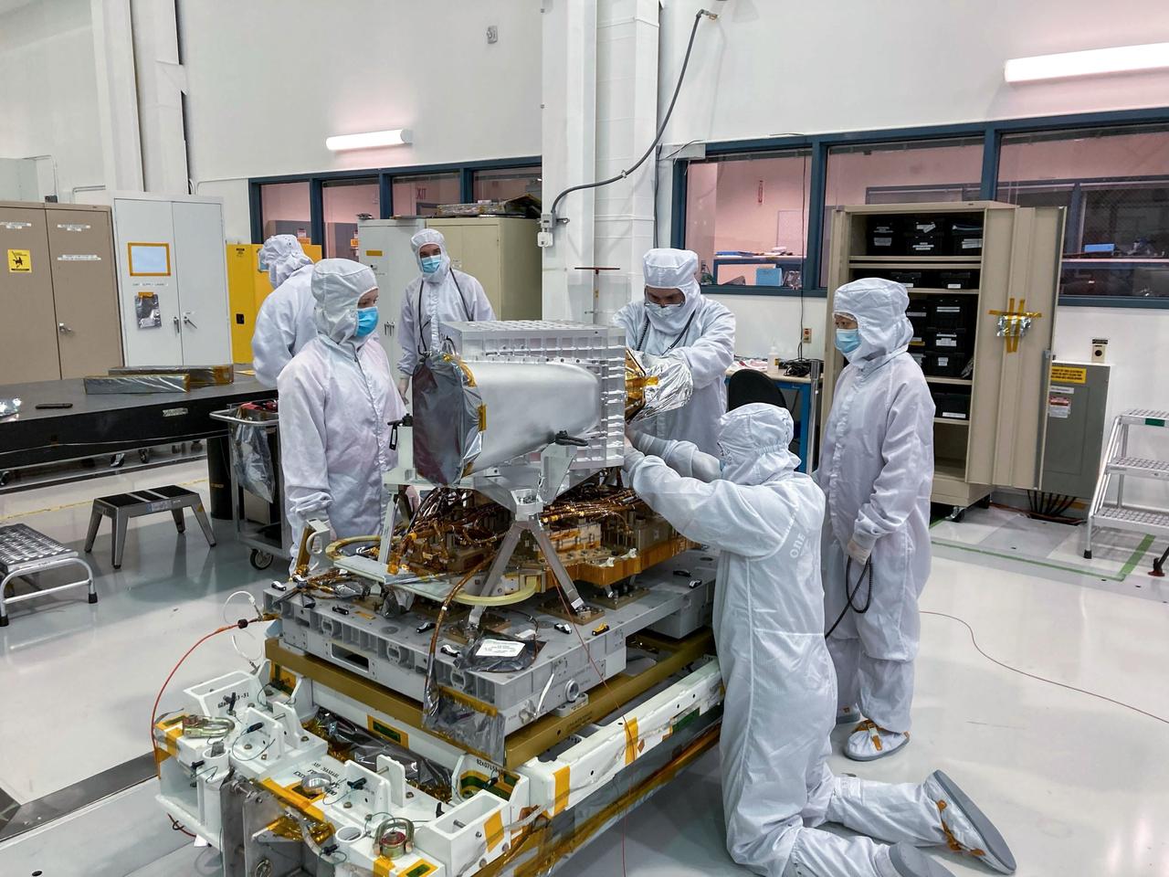
jsc2022e042616 (5/20/2022) --- The EMIT instrument before the enclosure panels were attached. The long tube in the foreground is the EMIT telescope baffle. The telescope resides in the large aluminum cube behind the baffle, and the spectrometer assembly is attached to the back of the telescope. The entire assembly is called the Optical Bench Assembly, or OBA. The OBA sits above the Electronics Mounting Plate, which is home to all of the instrument electronics and the cryocooler (not visible). Image courtesy of JPL.
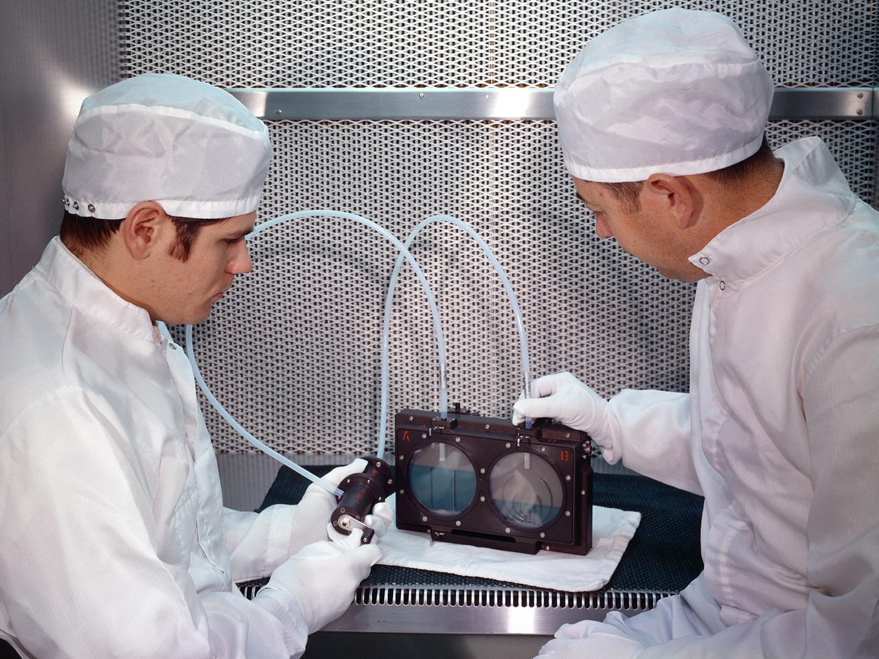
Two researchers at the National Aeronautics and Space Administration (NASA) Lewis Research Center demonstrate the test equipment they devised to study the transfer of liquid in microgravity onboard the Apollo 14 mission. The test was an early step in developing the ability to transfer liquids from a tanker vehicle to spacecraft in space. Researchers needed to know the tank’s outflow characteristics, the fluid’s behavior when entering new tank, and the effects of accelerations. Others had performed some calculations and analytical studies, but no one had examined the complete transfer from one tank to another in microgravity. The early calculations concluded that the transfer process was impossible without devices to control the liquid and gas. This investigation specifically sought to demonstrate the effectiveness of two different surface-tension baffle designs. The experiment was an entirely closed system with two baffled-tanks. The researchers also built a similar device without the baffles. The experiment was carried onboard the Apollo 14 spacecraft and conducted during the coast period on the way to the moon. The two surface tension baffle designs in the separate tanks were shown to be effective both as supply tanks and as receiver tanks. The liquid transferred within two percent of the design value with ingesting gas. The unbaffled tanks ingested gas after only 12-percent of the fluid had transferred.
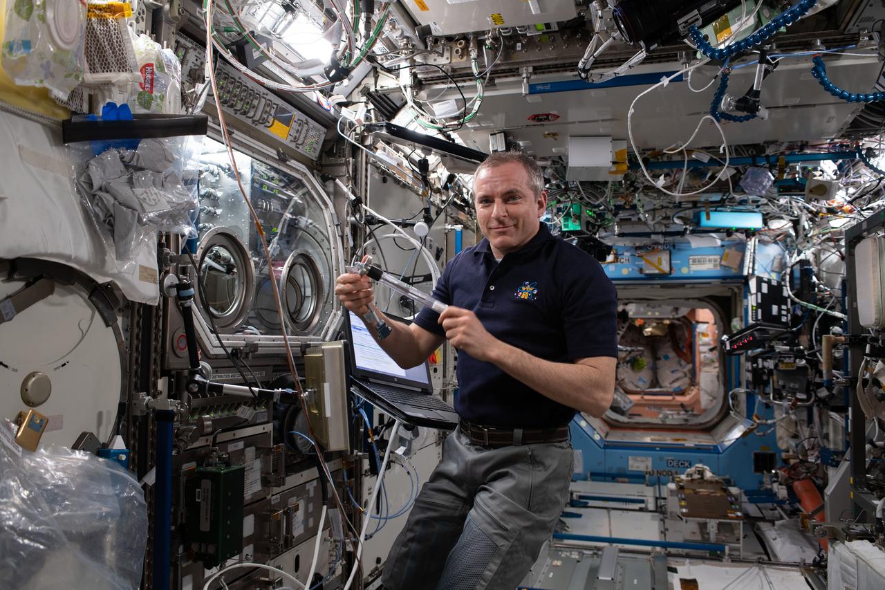
iss059e027344 (April 19, 2019) --- Astronaut David Saint-Jacques of the Canadian Space Agency studies how crystals melt and solidify using the Microgravity Science Glovebox inside the U.S. Destiny laboratory module. The Solidification Using a Baffle in Sealed Ampoules study explores how to produce high-quality semi-conductor crystals in microgravity.
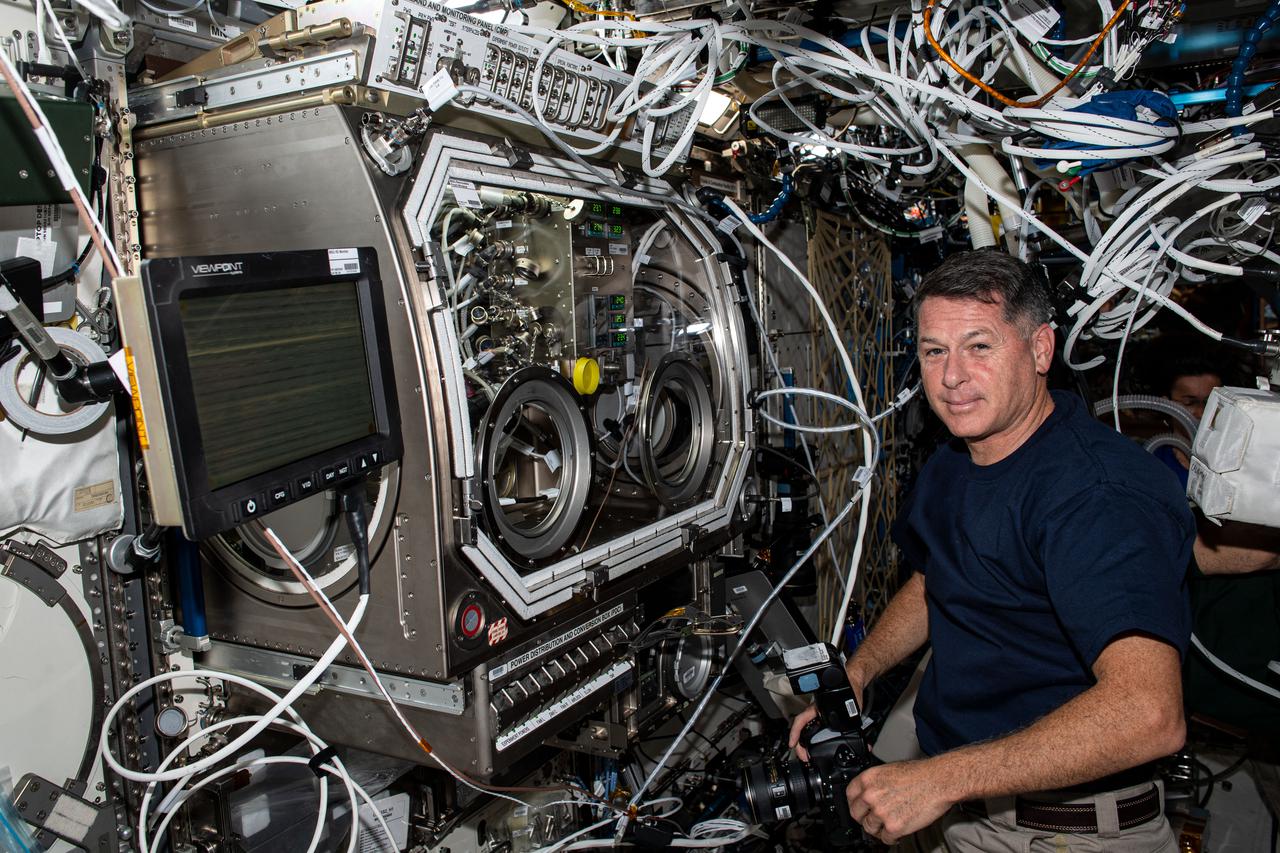
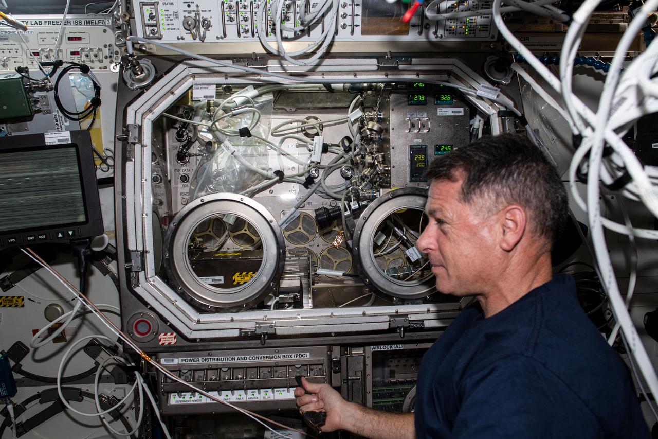
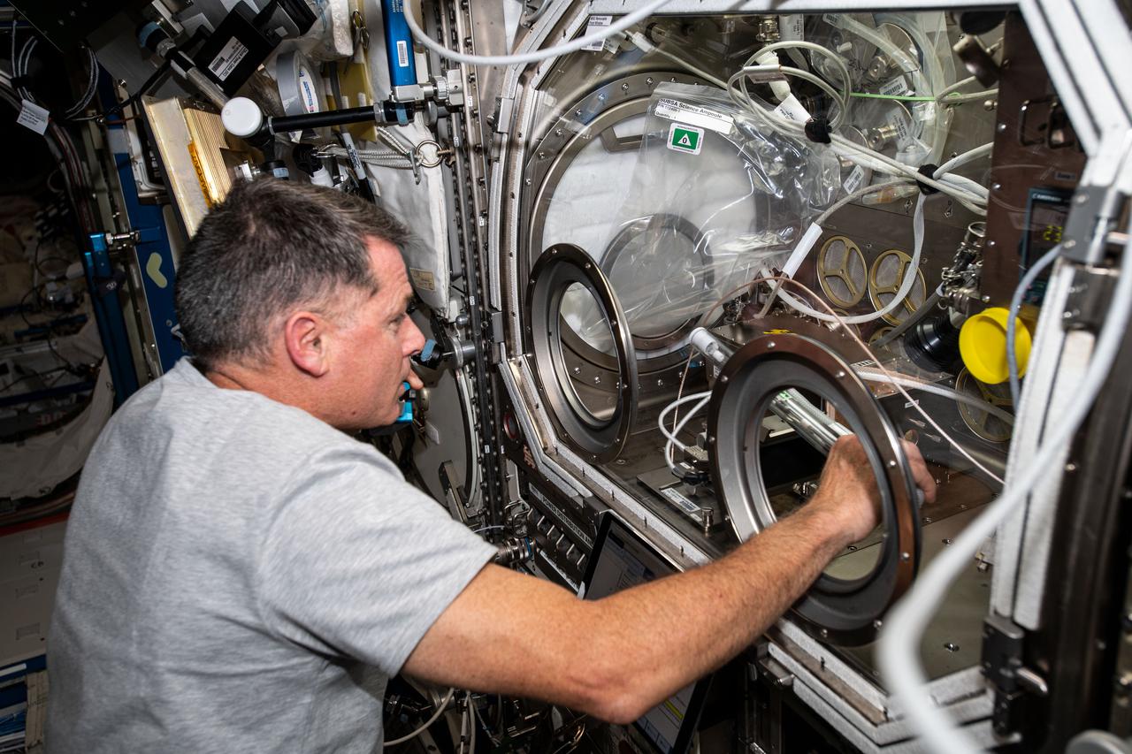
iss065e020575 (May 6, 2021) --- NASA astronaut and Expedition 65 Flight Engineer Shane Kimbrough sets up the U.S. Destiny laboratory module's Microgravity Science Glovebox for a physics investigation. The study known as Solidification Using a Baffle in Sealed Ampoules, or SUBSA, explores improving technology used in producing semiconductor crystals.

iss065e073965 (May 26, 2021) --- Expedition 65 Commander Akihiko Hoshide of the Japan Aerospace Exploration Agency checks out hardware for a physics experiment also known as SUBSA, or Solidification Using a Baffle in Sealed Ampoules. The space physics study is exploring ways to improve the production of semiconductor crystals.
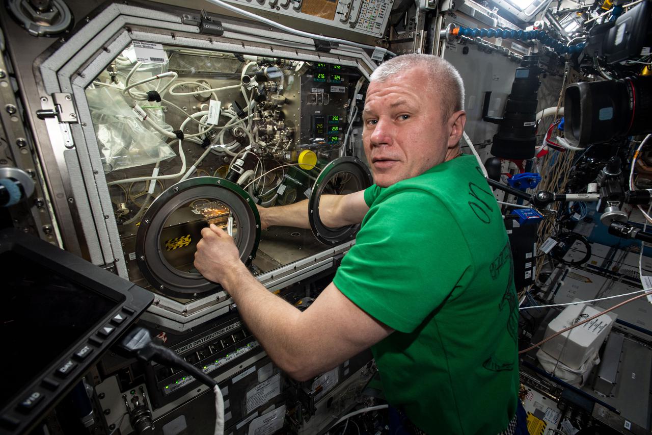
iss065e021208 (May 6, 2021) --- Roscosmos cosmonaut and Expedition 65 Flight Engineer Oleg Novitskiy swaps hardware inside the U.S. Destiny laboratory module's Microgravity Science Glovebox for a physics investigation. The study known as Solidification Using a Baffle in Sealed Ampoules, or SUBSA, explores improving technology used in producing semiconductor crystals.

iss066e044525 (Nov. 4, 2021) --- NASA astronaut and Expedition 66 Flight Engineer Mark Vande Hei works inside the Microgravity Science Glovebox setting up hardware for a space physics study, known as Solidification Using a Baffle in Sealed Ampoules (SUBSA), seeking to improve the production of higher quality semiconductor crystals.
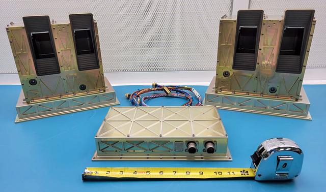
jsc2022e091372 (12/7/2022) --- The STP-H9-ECLIPSE flight hardware is shown prior to its delivery to NASA’s Johnson Space Center in March 2022. The box on the upper left in the image is the Cross-track Scanner (CTS), which views beneath the ISS and produces maps of the airglow emission. The sensor on the upper right is the Aft Limb-Scanner (ALS), which makes images of the ionospheric airglow behind the ISS in its orbit plane. The blackened rectangular structures on the boxes are the sunshade baffles around the openings to the SUVM mirrors, which are at the center of the baffles. The box near the bottom center is the Mission Operations Electronics (MOE), which controls the instruments and accepts commands from the ISS and relays data back to the ISS during the mission. The measuring tape in the image shows the size of the MOE box as approximately 11 inches wide. Image courtesy of the Naval Research Laboratory.
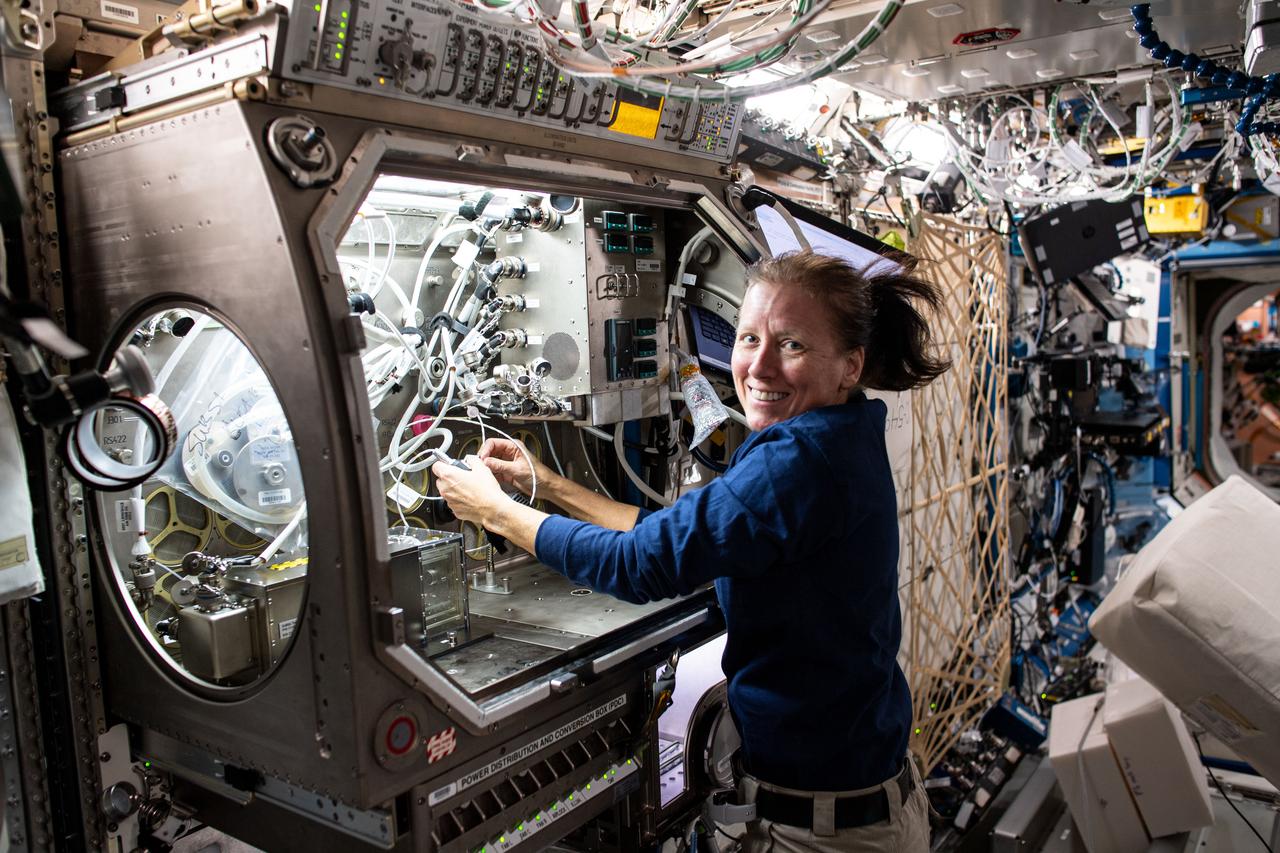
iss064e016385 (Dec. 29, 2020) --- NASA astronaut and Expedition 64 Flight Engineer Shannon Walker sets up hardware inside the Microgravity Science Glovebox for the Solidification Using a Baffle in Sealed Ampoules (SUBSA) experiment. SUBSA crystallizes melts in microgravity to learn more about the process of semiconductor crystal growth to benefit Earth and space industries. Results may lead to reduced fluid motion in the melt, leading to better distribution of subcomponents and the potential for improved technology used in producing semiconductor crystals.

iss065e084906 (June 1, 2021) --- Expedition 65 Flight Engineer Thomas Pesquet of ESA (European Space Agency) swaps samples inside the Microgravity Sciences Glovebox for an experiment called Solidification Using a Baffle in Sealed Ampoules, or SUBSA. The physics investigation explores experimental methods of crystallizing melts in microgravity and is expected to result in reduced fluid motion in the melt, leading to better distribution of subcomponents and the potential for improved technology used in producing semiconductor crystals.
iss065e020580 (May 5, 2021) --- NASA astronaut and Expedition 65 Flight Engineer Shane Kimbrough is pictured in front of the Microgravity Science Glovebox setting up hardware for a physics investigation. The experiment known as Solidification Using a Baffle in Sealed Ampoules, or SUBSA, explores experimental methods of crystallizing melts in microgravity and is expected to result in reduced fluid motion in the melt, leading to better distribution of subcomponents and the potential for improved technology used in producing semiconductor crystals.

ISS005-E-06787 (5 July 2002) --- Astronaut Peggy A. Whitson, Expedition Five flight engineer, works near the Microgravity Science Glovebox (MSG) in the Destiny laboratory on the International Space Station (ISS). Whitson spent much of the morning installing the Solidification Using a Baffle in Sealed Ampoules (SUBSA) experiment in the MSG. The SUBSA installation will be completed once the MSG is activated.
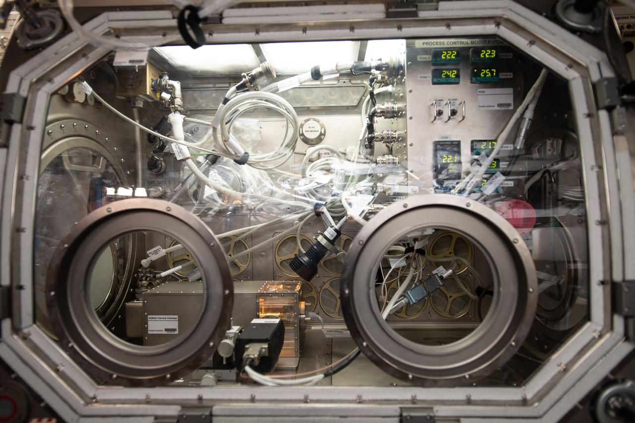
iss058e028142 (3/7/2019) --- View of the Microgravity Sciences Glovebox (MSG) during configuration of the SUBSA (Solidification Using Baffles in Sealed Ampoules) hardware in the MSG Work Volume in the Destiny Laboratory aboard the International Space Staion(ISS). SUBSA is a high-temperature furnace that can be used to study how microgravity affects the synthesis of semiconductor and scintillator crystals.
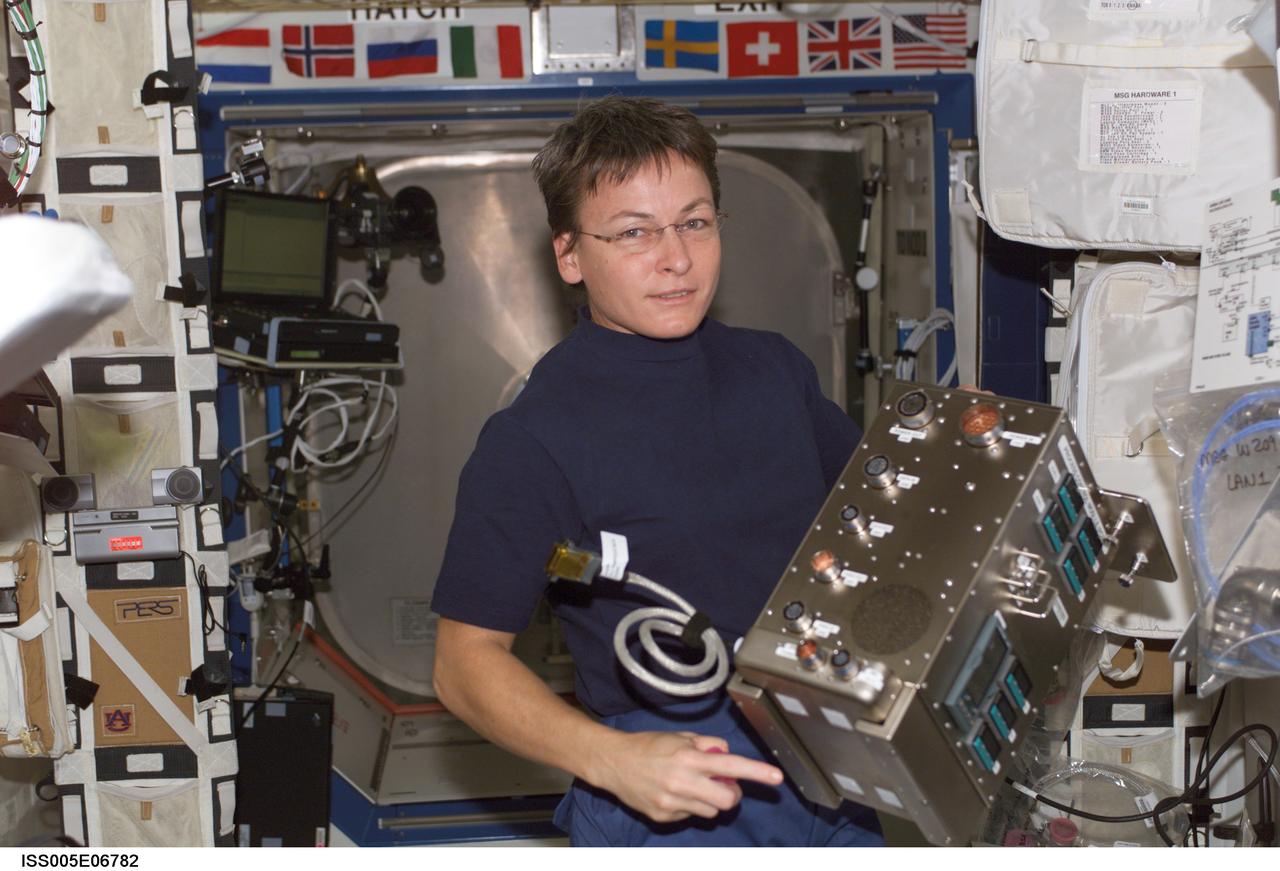
iss005e06782 (7/5/2002) --- NASA astronaut Peggy Whitson installs a Solidification Using a Baffle in Sealed Ampoules (SUBSA) Process Control Module in the Microgravity Science Glovebox (MSG). The SUBSA objective is to advance our understanding of the processes involved in semiconductor crystal growth. It offers a gradient freeze furnace for materials science investigations that can reach 850°C. Samples are contained in transparent quartz or ceramic ampoules with high definition video imaging available in real-time along with remote commanding of thermal control parameters.
iss065e050120 (May 21, 2021) --- NASA astronaut and Expedition 65 Flight Engineer Shane Kimbrough swaps samples inside the Microgravity Science Glovebox for an experiment called Solidification Using a Baffle in Sealed Ampoules, or SUBSA. The physics investigation explores experimental methods of crystallizing melts in microgravity and is expected to result in reduced fluid motion in the melt, leading to better distribution of subcomponents and the potential for improved technology used in producing semiconductor crystals.

iss064e032426 (Feb. 12, 2021) --- NASA astronaut and Expedition 64 Flight Engineer Michael Hopkins swaps samples inside the Microgravity Science Glovebox for the SUBSA (Solidification Using Baffles in Sealed Ampoules) experiment. The SUBSA physics study explores experimental methods of crystallizing melts in microgravity that may contribute to the production of higher quality semiconductor crystals.
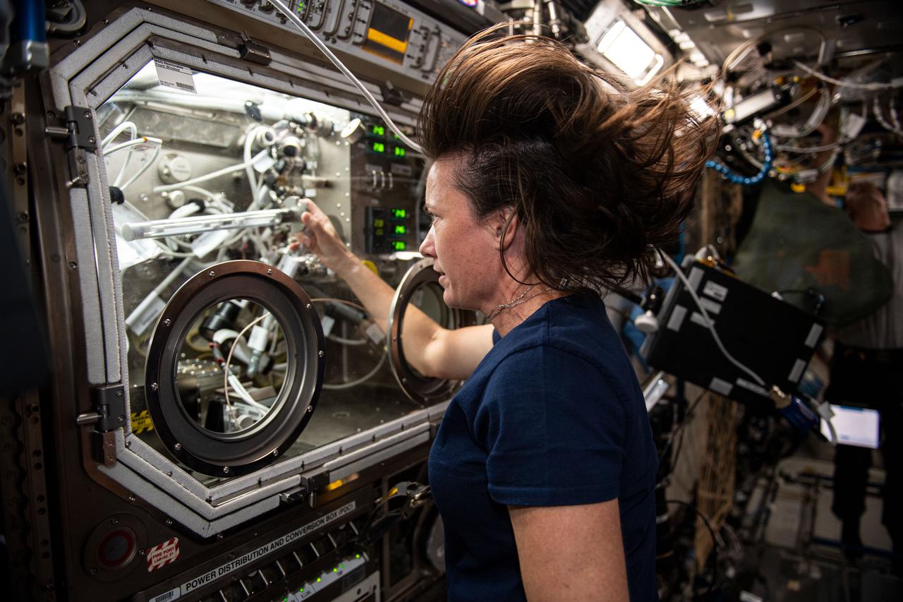
iss065e061407 (May 24, 2021) --- NASA astronaut and Expedition 65 Flight Engineer Megan McArthur works in the Microgravity Science Glovebox swapping samples for an experiment called Solidification Using a Baffle in Sealed Ampoules, or SUBSA. The physics investigation explores experimental methods of crystallizing melts in microgravity and is expected to result in reduced fluid motion in the melt, leading to better distribution of subcomponents and the potential for improved technology used in producing semiconductor crystals.
/MAF_20240201_CS3_LOX_VACtoCellD_06(EB)~medium.jpg)
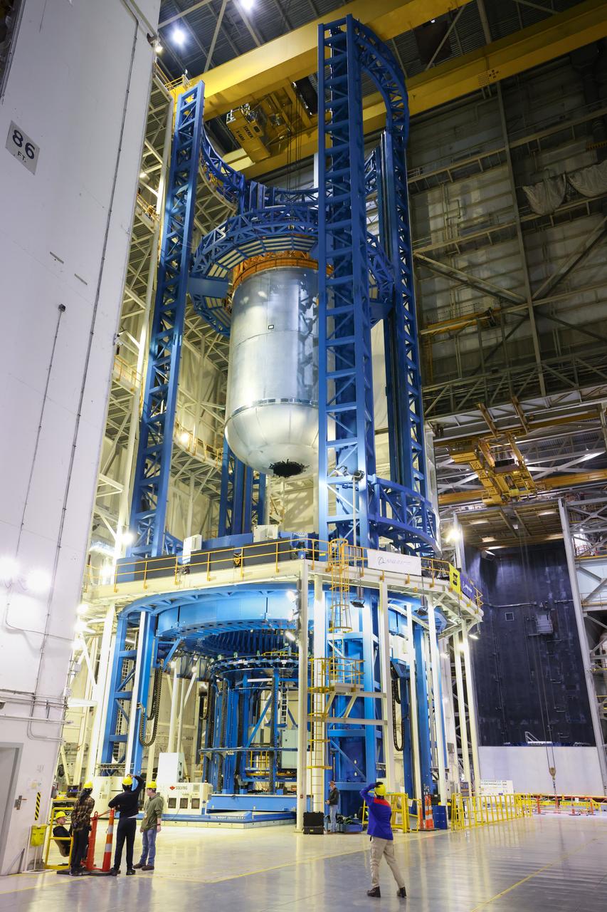
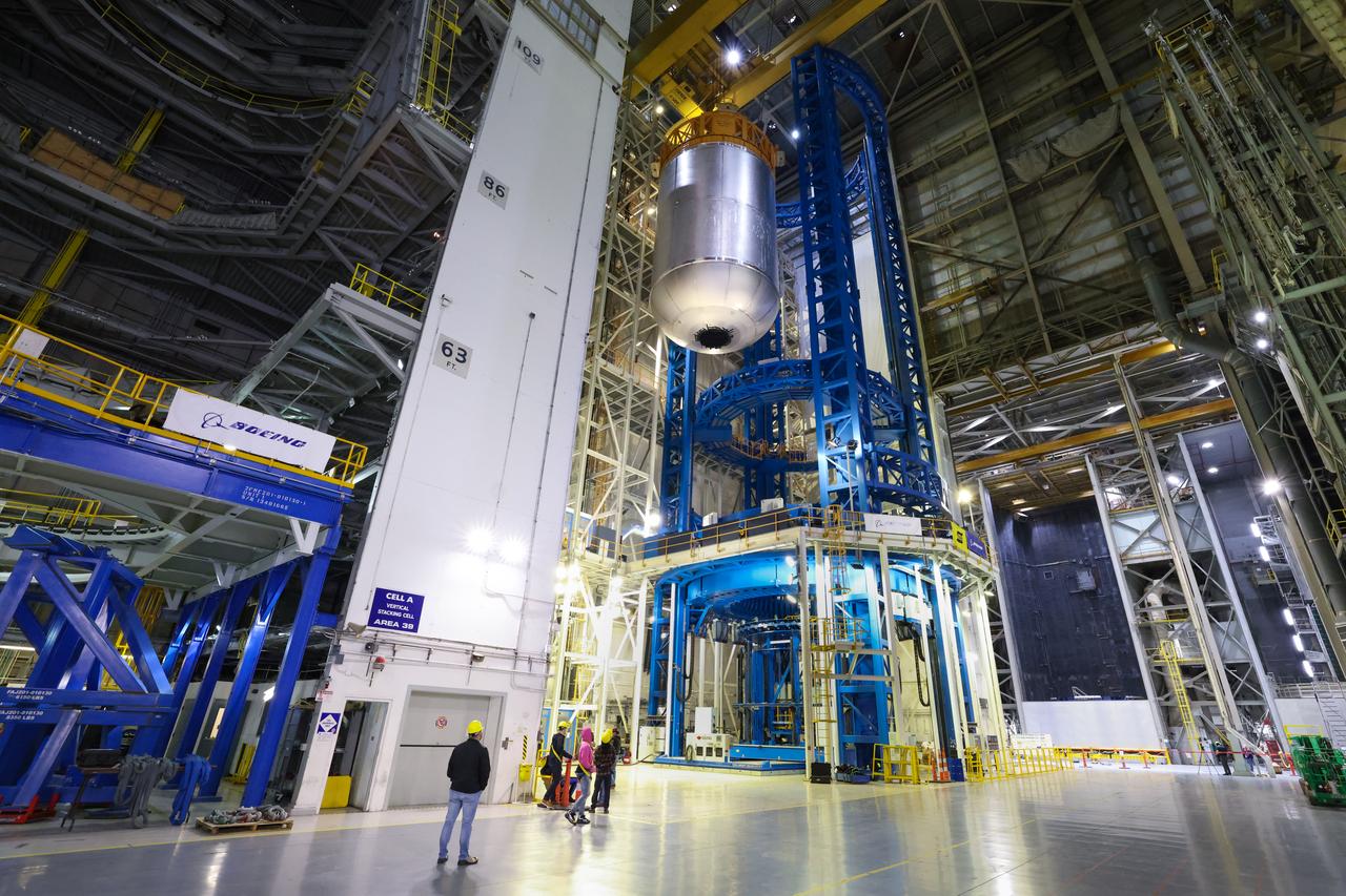
This imagery shows how technicians at NASA’s Michoud Assembly Facility in New Orleans moved the structurally complete liquid oxygen tank for NASA’s SLS (Space Launch System) after it was finished with welding Jan. 8. The tank will form part of the core stage for the SLS rocket that power NASA’s Artemis III mission to the Moon. The liquid oxygen tank is undergoing dimensional checks and partial baffle installation in Cell D. The liquid oxygen tank is one of five major components that make up the SLS rocket’s core stage. Together with the forward skirt, intertank, liquid hydrogen tank, engine section, along with the four RS-25 engines at its base, the 212-foot core stage will help power NASA’s Artemis missions to the Moon.
/MAF_20240201_CS3_LOX_VACtoCellD_07(EB)~medium.jpg)
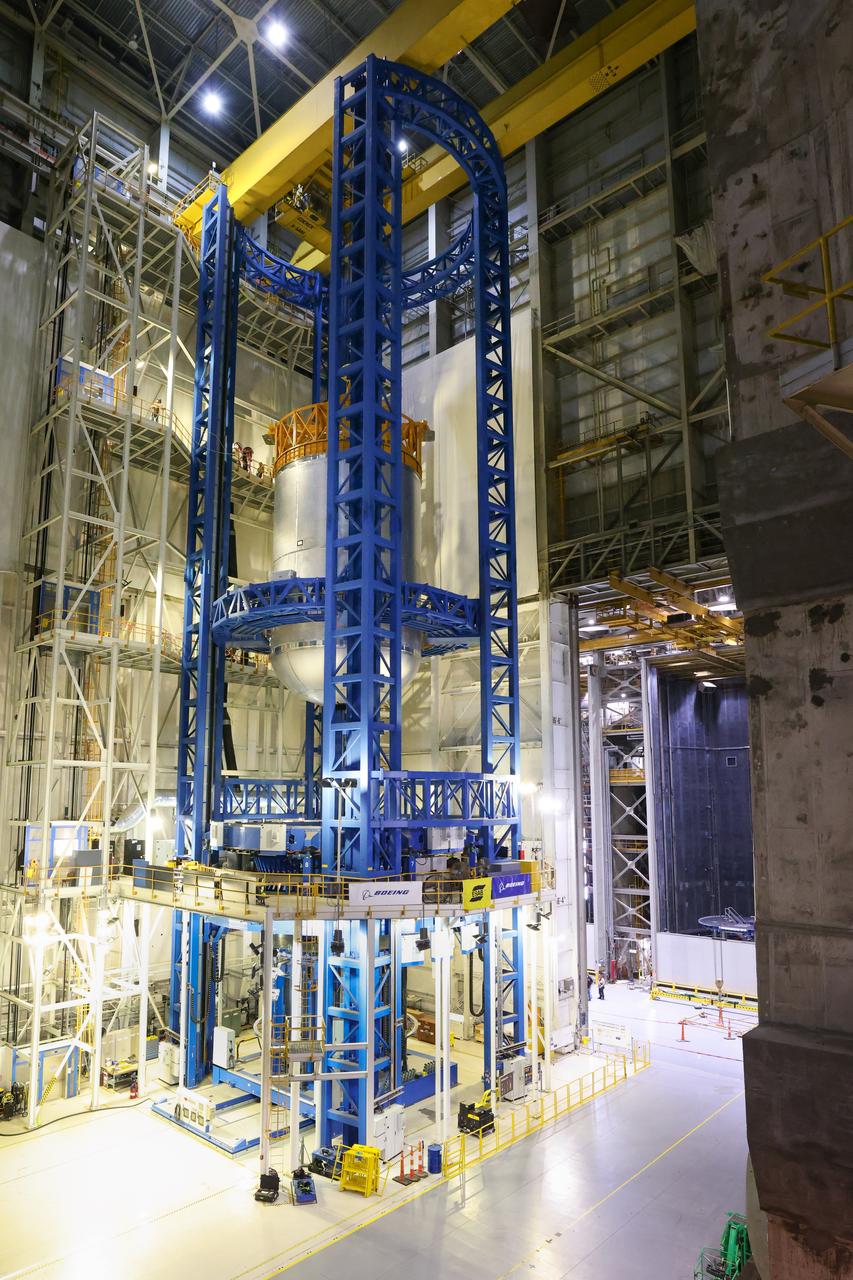
This imagery shows how technicians at NASA’s Michoud Assembly Facility in New Orleans moved the structurally complete liquid oxygen tank for NASA’s SLS (Space Launch System) after it was finished with welding Jan. 8. The tank will form part of the core stage for the SLS rocket that power NASA’s Artemis III mission to the Moon. The liquid oxygen tank is undergoing dimensional checks and partial baffle installation in Cell D. The liquid oxygen tank is one of five major components that make up the SLS rocket’s core stage. Together with the forward skirt, intertank, liquid hydrogen tank, engine section, along with the four RS-25 engines at its base, the 212-foot core stage will help power NASA’s Artemis missions to the Moon.
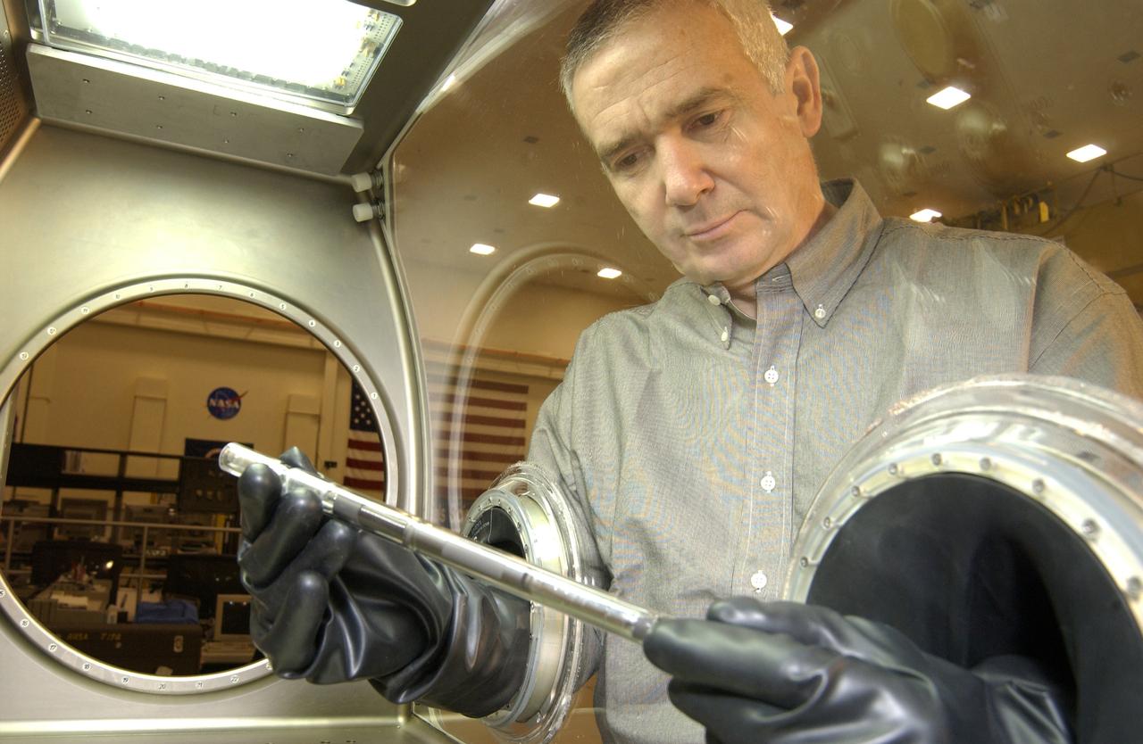
One of the first materials science experiments on the International Space Station -- the Solidification Using a Baffle in Sealed Ampoules (SUBSA) -- will be conducted during Expedition Five inside the Microgravity Science Glovebox. The glovebox is the first dedicated facility delivered to the Station for microgravity physical science research, and this experiment will be the first one operated inside the glovebox. The glovebox's sealed work environment makes it an ideal place for the furnace that will be used to melt semiconductor crystals. Astronauts can change out samples and manipulate the experiment by inserting their hands into a pair of gloves that reach inside the sealed box. Dr. Aleksandar Ostrogorsky, a materials scientist from the Rensselaer Polytechnic Institute, Troy, N.Y., and the principal investigator for the SUBSA experiment, uses the gloves to examine an ampoule like the ones used for his experiment inside the glovebox's work area. The Microgravity Science Glovebox and the SUBSA experiment are managed by NASA's Marshall Space Flight Center in Huntsville, Ala.
/MAF_20240201_CS3_LOX_VACtoCellD_03(EB)~medium.jpg)
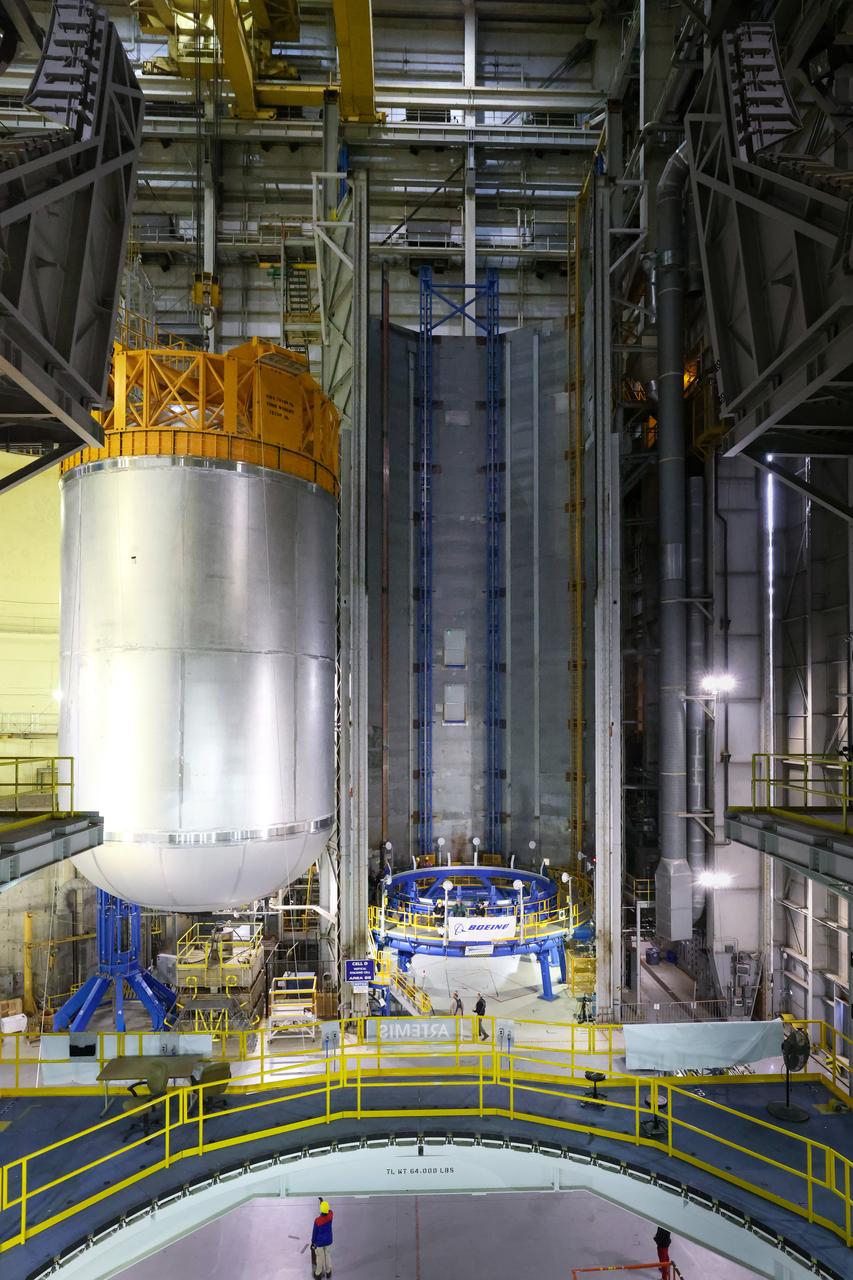
This imagery shows how technicians at NASA’s Michoud Assembly Facility in New Orleans moved the structurally complete liquid oxygen tank for NASA’s SLS (Space Launch System) after it was finished with welding Jan. 8. The tank will form part of the core stage for the SLS rocket that power NASA’s Artemis III mission to the Moon. The liquid oxygen tank is undergoing dimensional checks and partial baffle installation in Cell D. The liquid oxygen tank is one of five major components that make up the SLS rocket’s core stage. Together with the forward skirt, intertank, liquid hydrogen tank, engine section, along with the four RS-25 engines at its base, the 212-foot core stage will help power NASA’s Artemis missions to the Moon.
/MAF_20240201_CS3_LOX_VACtoCellD_02(EB)~medium.jpg)
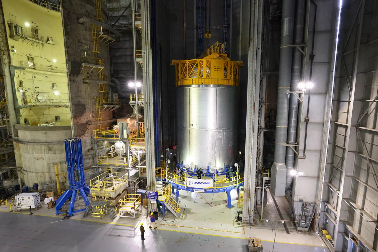
This imagery shows how technicians at NASA’s Michoud Assembly Facility in New Orleans moved the structurally complete liquid oxygen tank for NASA’s SLS (Space Launch System) after it was finished with welding Jan. 8. The tank will form part of the core stage for the SLS rocket that power NASA’s Artemis III mission to the Moon. The liquid oxygen tank is undergoing dimensional checks and partial baffle installation in Cell D. The liquid oxygen tank is one of five major components that make up the SLS rocket’s core stage. Together with the forward skirt, intertank, liquid hydrogen tank, engine section, along with the four RS-25 engines at its base, the 212-foot core stage will help power NASA’s Artemis missions to the Moon.
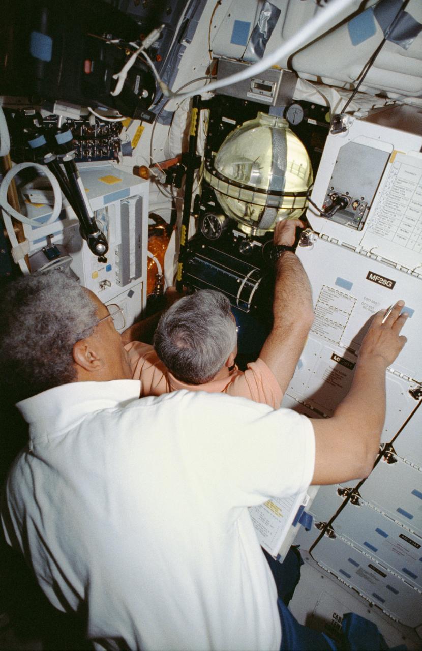
STS053-04-018 (2-9 Dec 1992) --- Astronauts Guion S. Bluford (left) and Michael R. U. (Rich) Clifford monitor the Fluid Acquisition and Resupply Equipment (FARE) onboard the Space Shuttle Discovery. Clearly visible in the mid-deck FARE setup is one of two 12.5-inch spherical tanks made of transparent acrylic, one to supply and one to receive fluids. The purpose of FARE is to investigate the dynamics of fluid transfer in microgravity and develop methods for transferring vapor-free propellants and other liquids that must be replenished in long-term space systems like satellites, Extended-Duration Orbiters (EDO), and Space Station Freedom. Eight times over an eight-hour test period, the mission specialists conducted the FARE experiment. A sequence of manual valve operations caused pressurized air from the bottles to force fluids from the supply tank to the receiver tank and back again to the supply tank. Baffles in the receiver tank controlled fluid motion during transfer, a fine-mesh screen filtered vapor from the fluid, and the overboard vent removed vapor from the receiver tank as the liquid rose. FARE is managed by NASA's Marshall Space Flight Center (MSFC) in Alabama. The basic equipment was developed by Martin Marietta for the Storable Fluid Management Demonstration. Susan L. Driscoll is the principal investigator.
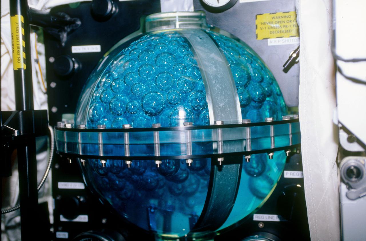
STS053-09-019 (2 - 9 Dec 1992) --- A medium close-up view of part of the Fluid Acquisition and Resupply Equipment (FARE) onboard the Space Shuttle Discovery. Featured in the mid-deck FARE setup is fluid activity in one of two 12.5-inch spherical tanks made of transparent acrylic. Pictured is the receiver tank. The other tank, out of frame below, is for supplying fluids. The purpose of FARE is to investigate the dynamics of fluid transfer in microgravity and develop methods for transferring vapor-free propellants and other liquids that must be replenished in long-term space systems like satellites, Extended-Duration Orbiters (EDO), and Space Station Freedom. Eight times over an eight-hour test period, the mission specialists conducted the FARE experiment. A sequence of manual valve operations caused pressurized air from the bottles to force fluids from the supply tank to the receiver tank and back again to the supply tank. Baffles in the receiver tank controlled fluid motion during transfer, a fine-mesh screen filtered vapor from the fluid, and the overboard vent removed vapor from the receiver tank as the liquid rose. FARE is managed by NASA's Marshall Space Flight Center (MSFC) in Alabama. The basic equipment was developed by Martin Marietta for the Storable Fluid Management Demonstration. Susan L. Driscoll is the principal investigator.

Expedition Five flight engineer Peggy Whitson is shown installing the Solidification Using a Baffle in Sealed Ampoules (SUBSA) experiment in the Microgravity Science Glovebox (MSG) in the Destiny laboratory aboard the International Space Station (ISS). SUBSA examines the solidification of semiconductor crystals from a melted material. Semiconductor crystals are used for many products that touch our everyday lives. They are found in computer chips, integrated circuits, and a multitude of other electronic devices, such as sensors for medical imaging equipment and detectors of nuclear radiation. Materials scientists want to make better semiconductor crystals to be able to further reduce the size of high-tech devices. In the microgravity environment, convection and sedimentation are reduced, so fluids do not remove and deform. Thus, space laboratories provide an ideal environment of studying solidification from the melt. This investigation is expected to determine the mechanism causing fluid motion during production of semiconductors in space. It will provide insight into the role of the melt motion in production of semiconductor crystals, advancing our knowledge of the crystal growth process. This could lead to a reduction of defects in semiconductor crystals produced in space and on Earth.
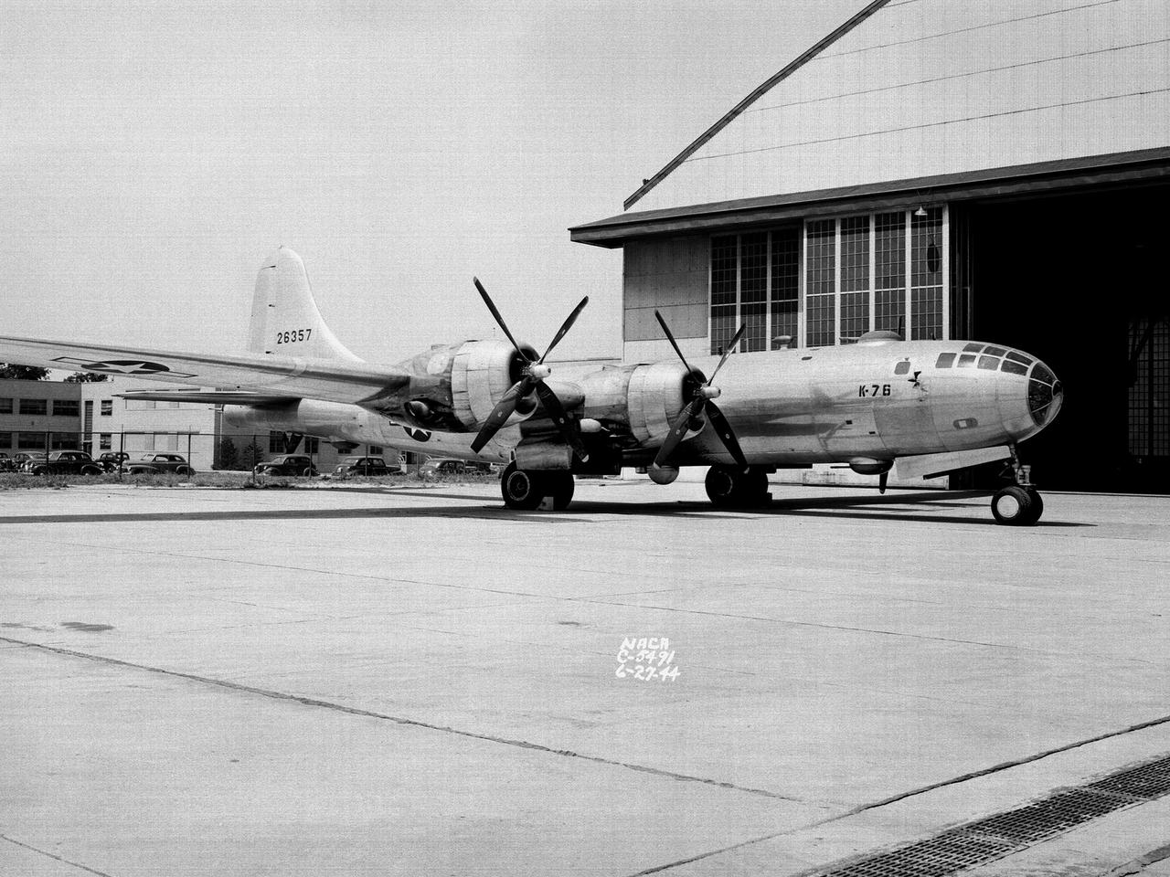
A Boeing B–29 Superfortress at the National Advisory Committee for Aeronautics (NACA) Aircraft Engine Research Laboratory in Cleveland, Ohio. The B–29 was the Army Air Forces’ deadliest weapon during the latter portion of World War II. The aircraft was significantly larger than previous bombers but could fly faster and higher. The B–29 was intended to soar above anti-aircraft fire and make pinpoint drops onto strategic targets. The bomber was forced to carry 20,000 pounds more armament than it was designed for. The extra weight pushed the B–29’s four powerful Wright R–3350 engines to their operating limits. The over-heating of the engines proved to be a dangerous problem. The military asked the NACA to tackle the issue. Full-scale engine tests on a R–3350 engine in the Prop House demonstrated that a NACA-designed impeller increased the flow rate of the fuel injection system. Altitude Wind Tunnel studies of the engine led to the reshaping of cowling inlet and outlet to improve airflow and reduce drag. Single-cylinder studies on valve failures were resolved by a slight extension of the cylinder head, and the Engine Research Building researchers combated uneven heating with a new fuel injection system. The modifications were then tried out on an actual B–29. The bomber arrived in Cleveland on June 22, 1944. The new injection impeller, ducted head baffles and instrumentation were installed on the bomber’s two left wing engines. Eleven test flights were flown over the next month with military pilots at the helm. Overall the flight tests corroborated the wind tunnel and test stand studies.
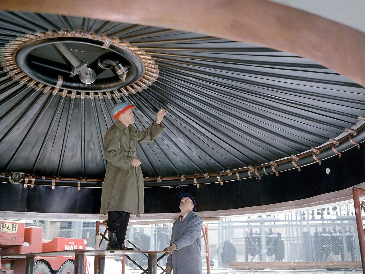
Engineers at the National Aeronautics and Space Administration (NASA) Lewis Research Center inspect the nitrogen baffle in the interior of the 22.5-foot diameter dome at the Space Power Chambers. In 1961 NASA Lewis management decided to convert the Altitude Wind Tunnel into two large test chambers and renamed the facility the Space Power Chambers. The conversion, which took over two years, included removing the tunnel’s drive fan, exhaust scoop, and turning vanes from the east end and inserting bulkheads to seal off the new chambers within the tunnel. The eastern section of the tunnel became a vacuum chamber capable of simulating 100 miles altitude. In 1962 NASA management decided to use the new vacuum chamber exclusively to study the second-stage rocket. This required significant modifications to the new tank and extensive test equipment to create a space environment. The Lewis test engineers sought to subject the Centaur to long durations in conditions that would replicate those encountered during its missions in space. The chamber was already capable of creating the vacuum of space, but the test engineers also wanted to simulate the cryogenic temperatures and solar radiation found in space. Six panels of 500-watt tungsten-iodine lamps were arranged around the Centaur to simulate the effect of the Sun’s heat. A large copper cold wall with its interior coated with heat-absorbing black paint was created specifically for these tests and assembled around the Centaur. The 42-foot-high wall had vertical ribs filled with liquid nitrogen which produced the low temperatures.