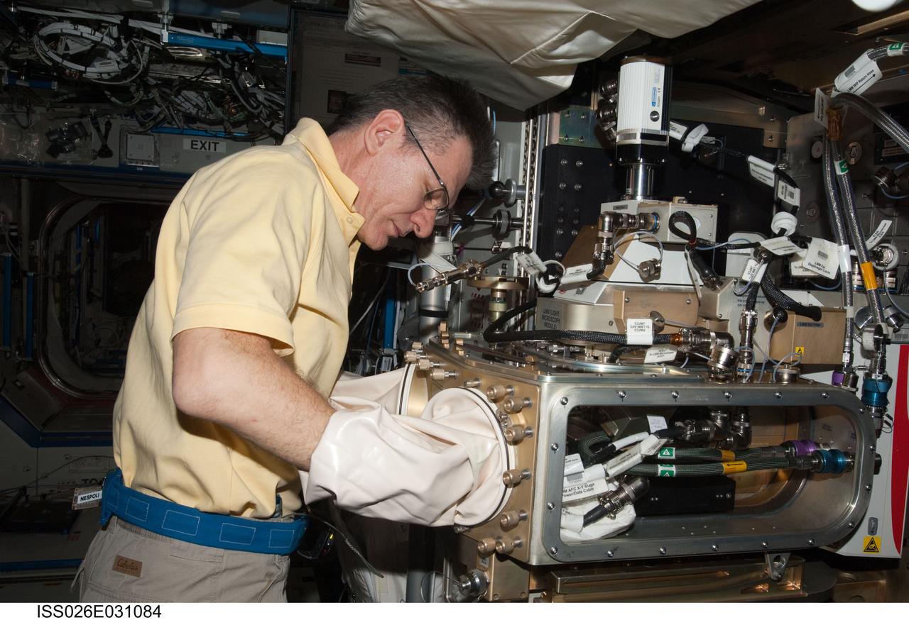
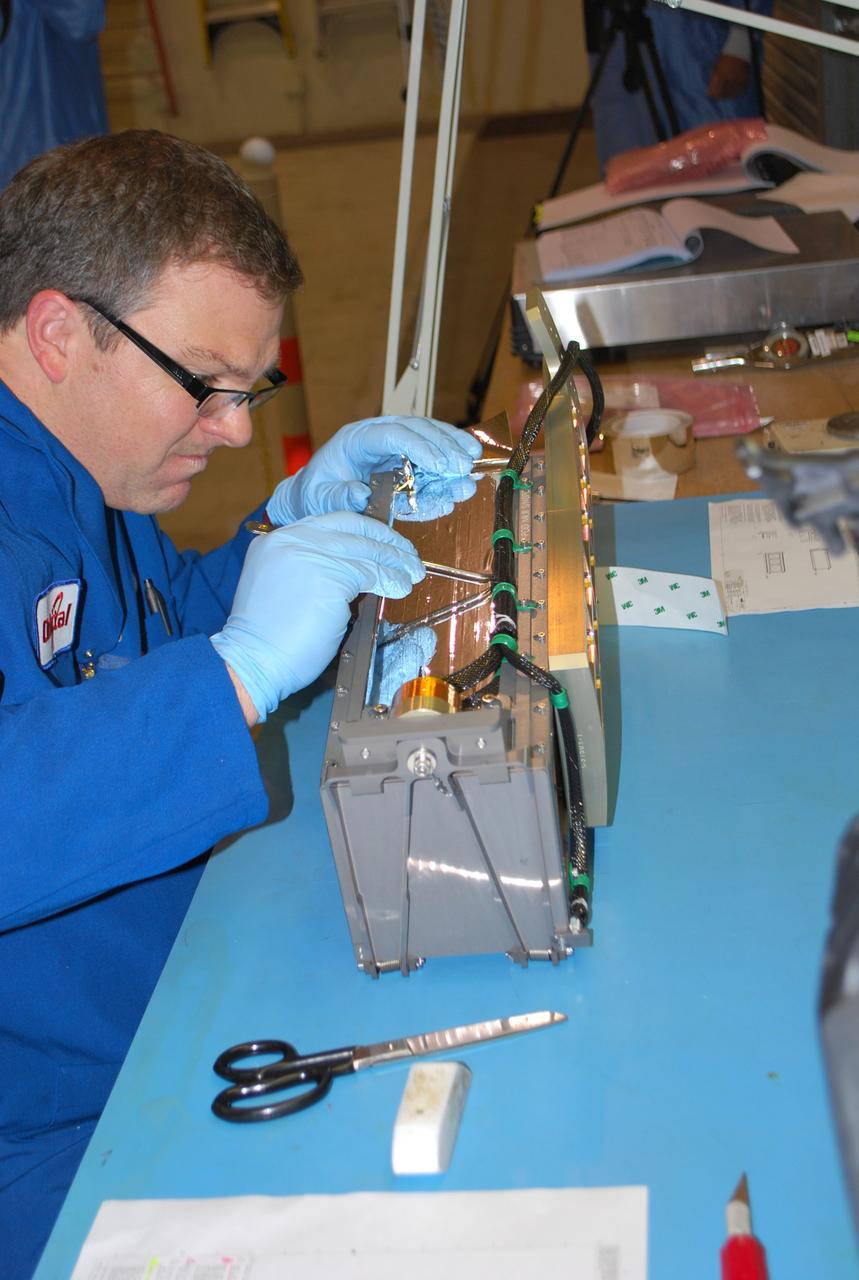
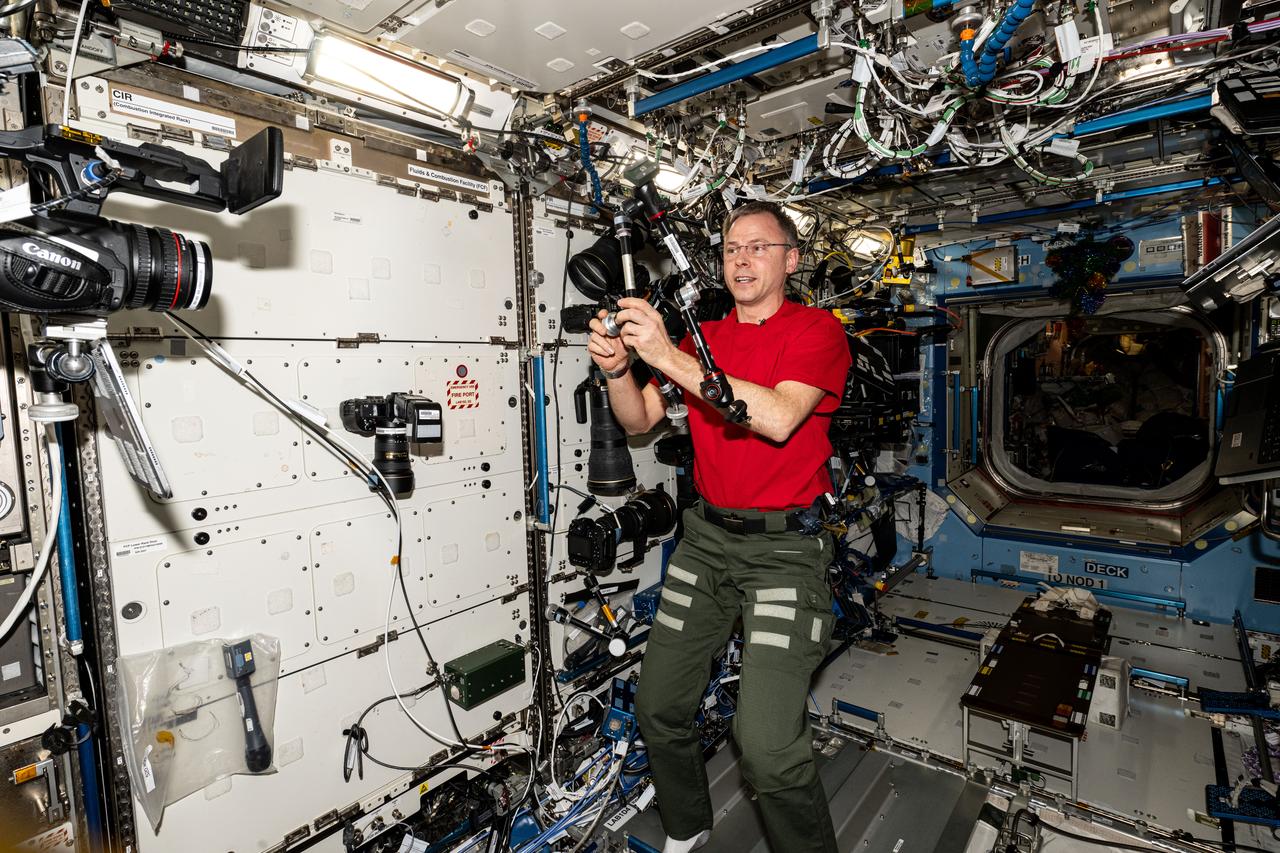
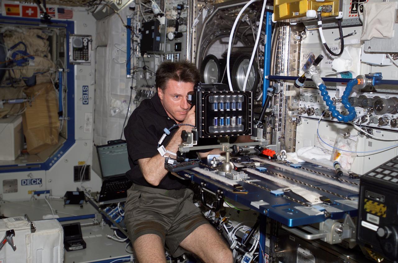
ISS026-E-031084 (1 March 2011) --- European Space Agency astronaut Paolo Nespoli, Expedition 26 flight engineer, works with the Light Microscopy Module (LMM) Spindle Bracket Assembly in the Fluids Integrated Rack (FIR) in the Destiny laboratory of the International Space Station.
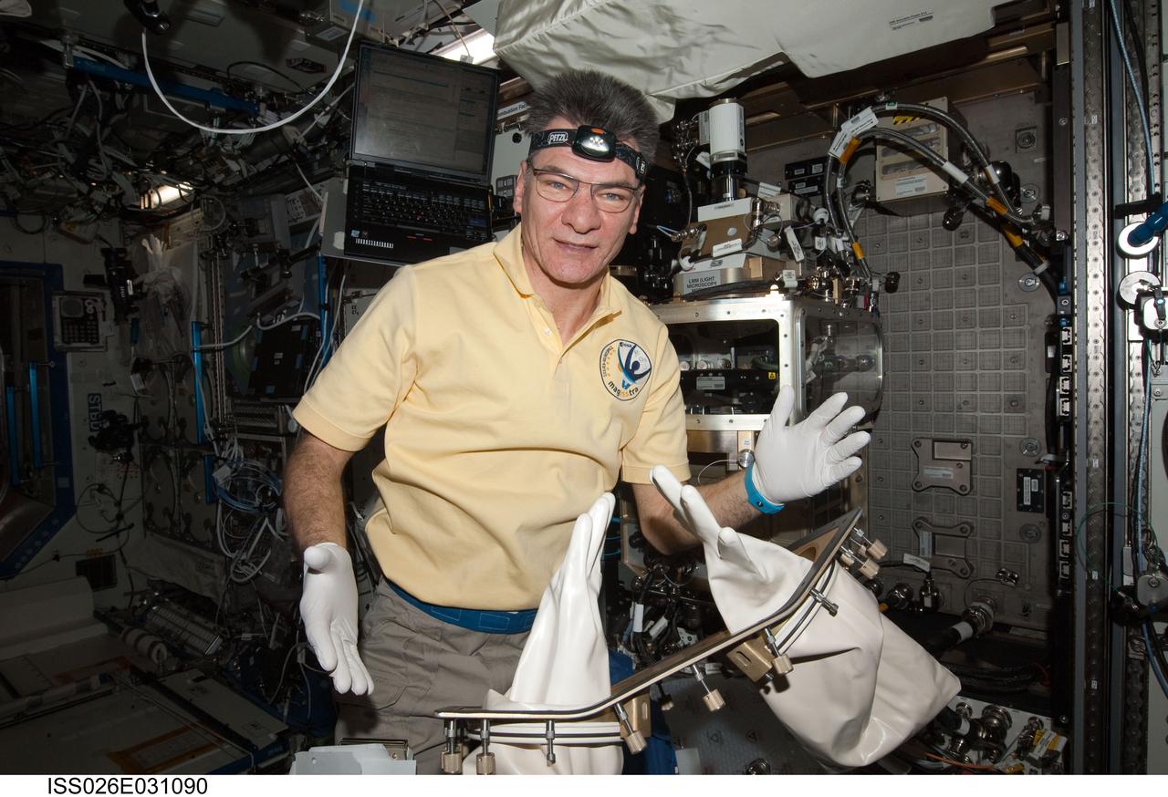
ISS026-E-031090 (1 March 2011) --- European Space Agency astronaut Paolo Nespoli, Expedition 26 flight engineer, works with the Light Microscopy Module (LMM) Spindle Bracket Assembly in the Fluids Integrated Rack (FIR) in the Destiny laboratory of the International Space Station.
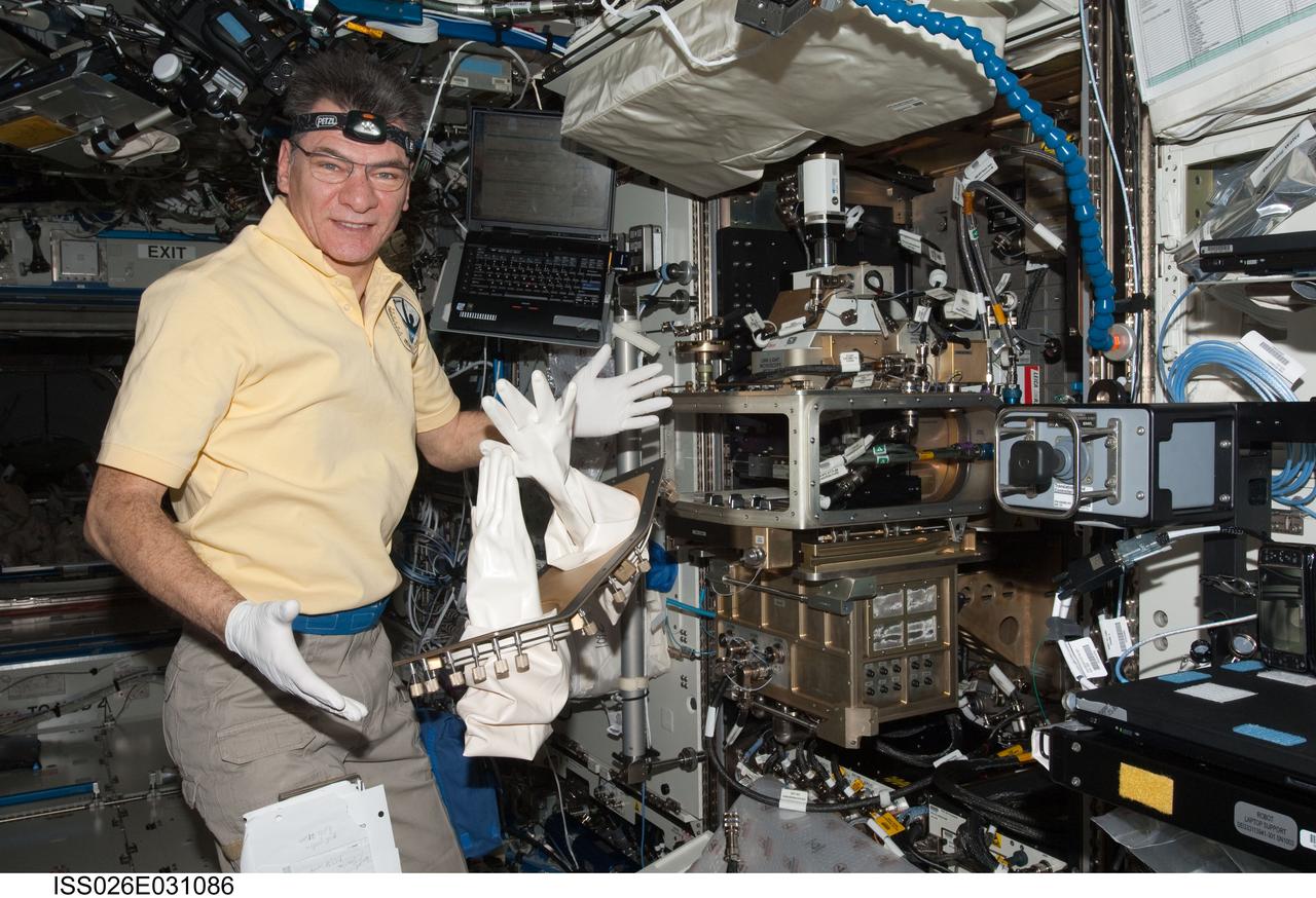
ISS026-E-031086 (1 March 2011) --- European Space Agency astronaut Paolo Nespoli, Expedition 26 flight engineer, works with the Light Microscopy Module (LMM) Spindle Bracket Assembly in the Fluids Integrated Rack (FIR) in the Destiny laboratory of the International Space Station.
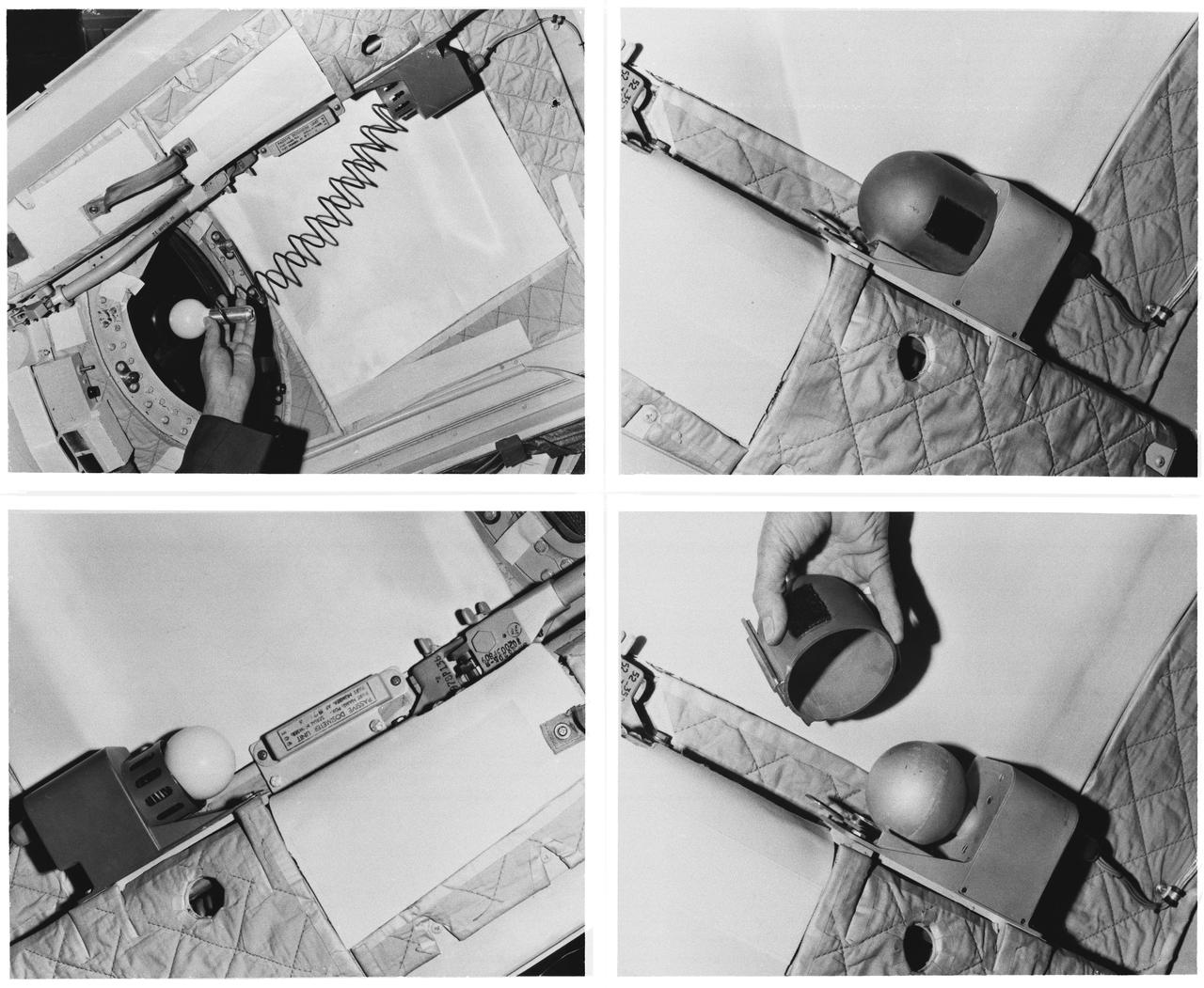
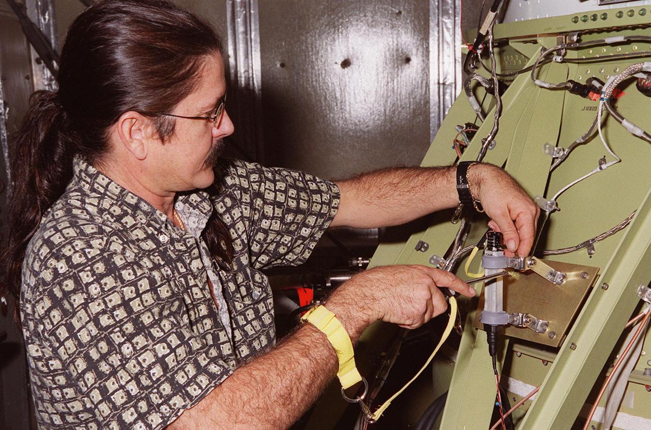
S65-61788 (For release: 11 Dec. 1965) --- Close-up view of equipment which will be used in the D-8 (Radiation in Spacecraft) experiment on the National Aeronautics and Space Administration's Gemini-6 spaceflight. This experiment is designed to make highly accurate measurements of the absorbed dose rate of radiation which penetrates the Gemini spacecraft, and determine the spatial distribution of dose levels inside the spacecraft particularly in the crew area. This is experimentation of the U.S. Air Force Weapons Laboratory, Kirtland AFB, N.M. LOWER LEFT: The second ionization chamber, this one is unshielded. This chamber can be removed from its bracket by the astronaut who will periodically take measurements at various locations in the spacecraft. Nearby is Passive Dosimeter Unit which is one of five small packets each containing a standard pocket ionization chamber, gamma electron sensitive film, glass needles and thermo luminescent dosimeters which are mounted at various locations in the cabin. UPPER LEFT: Photo illustrates how ionization chamber can be removed from bracket for measurements. LOWER RIGHT: Shield of bulb-shaped chamber will be removed (shown in photo) as the spacecraft passes through the South Atlantic anomaly, the area where the radiation belt dips closest to Earth's surface. UPPER RIGHT: Dome-shaped object is shield covering one of two Tissue Equivalent Ionization Chambers (sensors) which will read out continuously the instantaneous rate at which dose is delivered during the flight. This chamber is mounted permanently. The information will be recorded aboard the spacecraft, and will also be received directly by ground stations. This chamber is shielded to simulate the amount of radiation the crew members are receiving beneath their skin. Photo credit: NASA or National Aeronautics and Space Administration
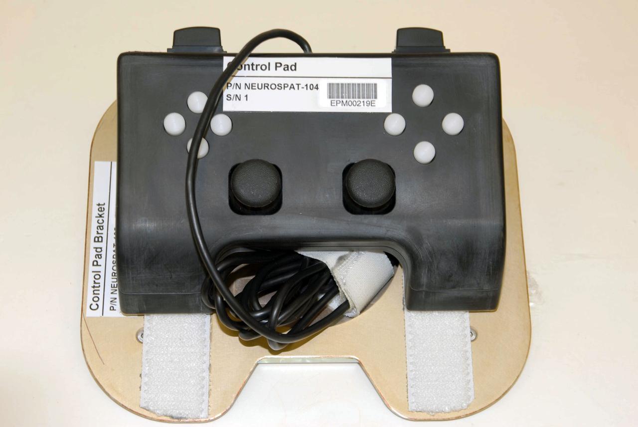
jsc2008e032966 (Apr. 9, 2008) --- Neurospat Control pad bracket at NASA's Johnson Space Center to be delivered to the International Space Station (ISS). Neurospat investigates ways in which crew member's three-dimensional visual and space perception is affected by long-duration stays in weightlessness to help in help in finding and developing countermeasures alleviating any disorientation experienced by astronauts.
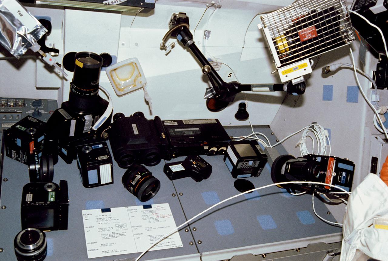
This array of photographic equipment, displayed on the aft flight deck payload station, represents just a part of the imaging and recording hardware which was carried aboard Discovery, Orbiter Vehicle (OV) 103, for STS-31's five day mission. Lenses, film magazines, cassettes, recorders, camera chassis, a pair of binoculars, spot meter, tape recorder, and a bracket-mounted light fixture are included among the array.
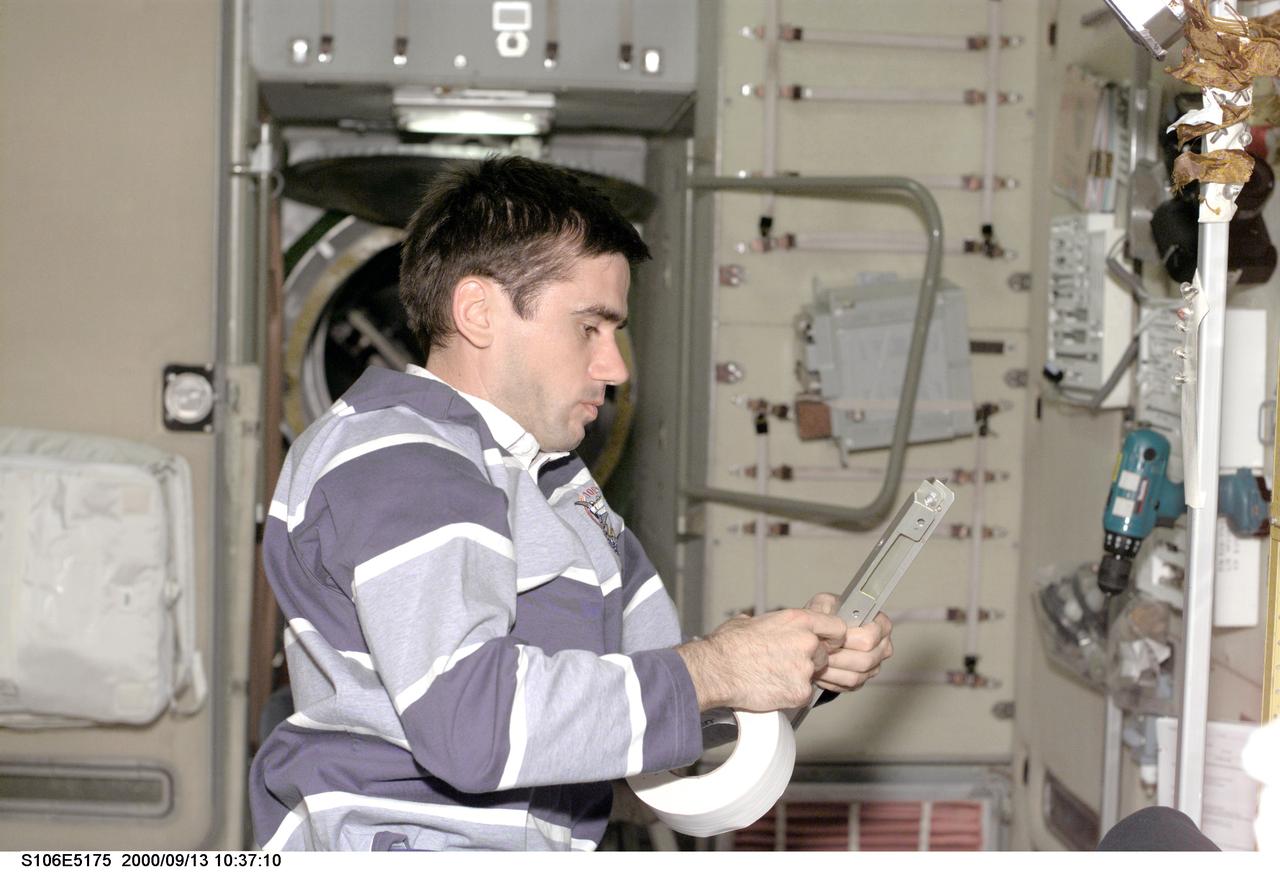
S106-E-5175 (13 September) --- Cosmonaut Yuri I. Malenchenko, representing the Russian Aviation and Space Agency, tapes brackets for the Zvezda during work on the service module. The mission specialist and the other STS-106 astronauts and cosmonaut are continuing electrical work and transfer activities as they near the halfway point of docked operations with the International Space Station. In all the crew will have 189 hours, 40 minutes of planned Atlantis-ISS docked time.
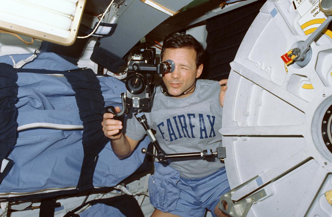
STS-36 Mission Specialist (MS) Pierre J. Thuot operates 16mm ARRIFLEX motion picture camera mounted on the open airlock hatch via a bracket. Thuot uses the camera to record activity of his fellow STS-36 crewmembers on the middeck of Atlantis, Orbiter Vehicle (OV) 104. Positioned between the airlock hatch and the starboard wall-mounted sleep restraints, Thuot, wearing a FAIRFAX t-shirt, squints into the cameras eye piece. Thuot and four other astronauts spent four days, 10 hours and 19 minutes aboard OV-104 for the Department of Defense (DOD) devoted mission.
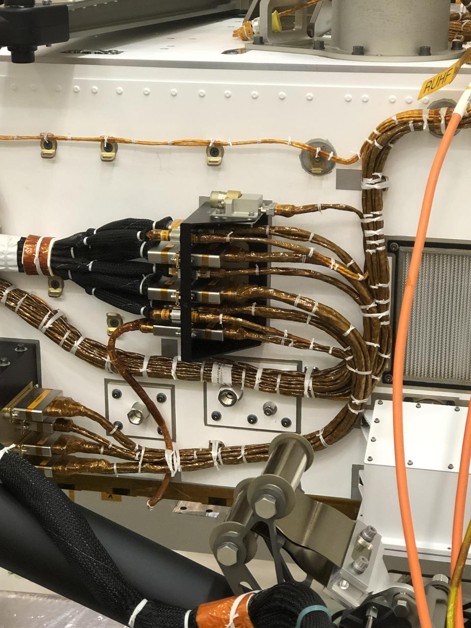
Components are visible on the port side of the Perseverance rover in this close-up image taken on Nov. 16, 2019, in High Bay 1 of the Spacecraft Assembly Facility at NASA's Jet Propulsion Laboratory in Southern California. At center of the image, attached to the side of the rover, is a black cable bracket (with gold cabling running through it). Attached to the top of this black bracket — and gray in color — is the Entry Descent and Landing (EDL) microphone. Below the cable bracket are the Mars Oxygen In-Situ Resource Utilization Experiment (MOXIE) wall ports. The orange cable passing over it is part of ground support equipment. https://photojournal.jpl.nasa.gov/catalog/PIA24046
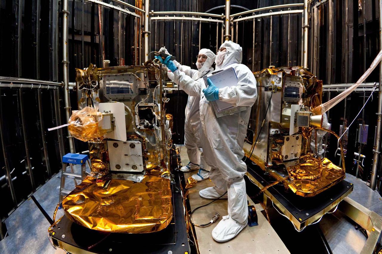
In this photo, taken April 29, 2011, technicians install lifting brackets prior to hoisting the 200-kilogram 440-pound GRAIL-A spacecraft out of vacuum chamber after testing.
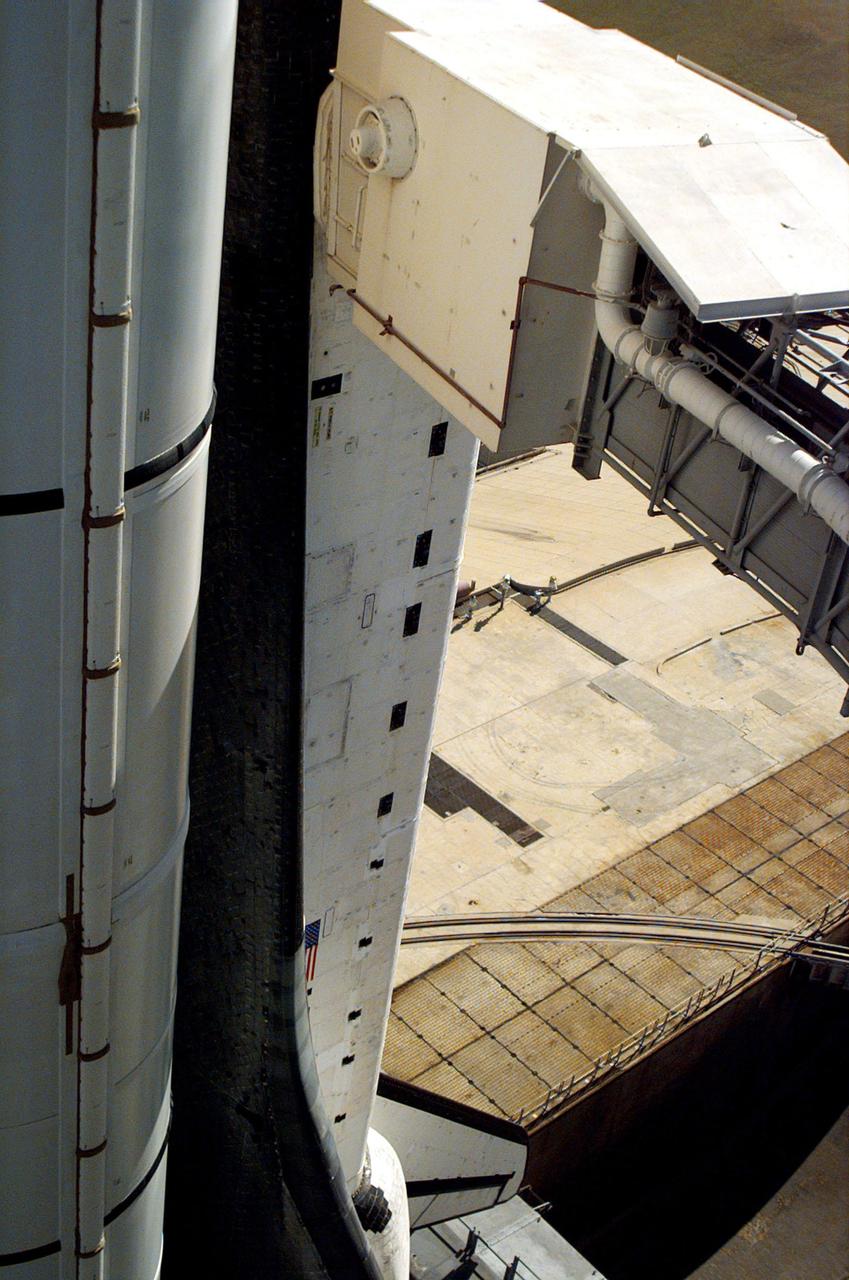
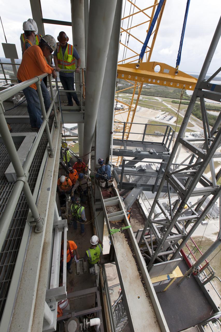
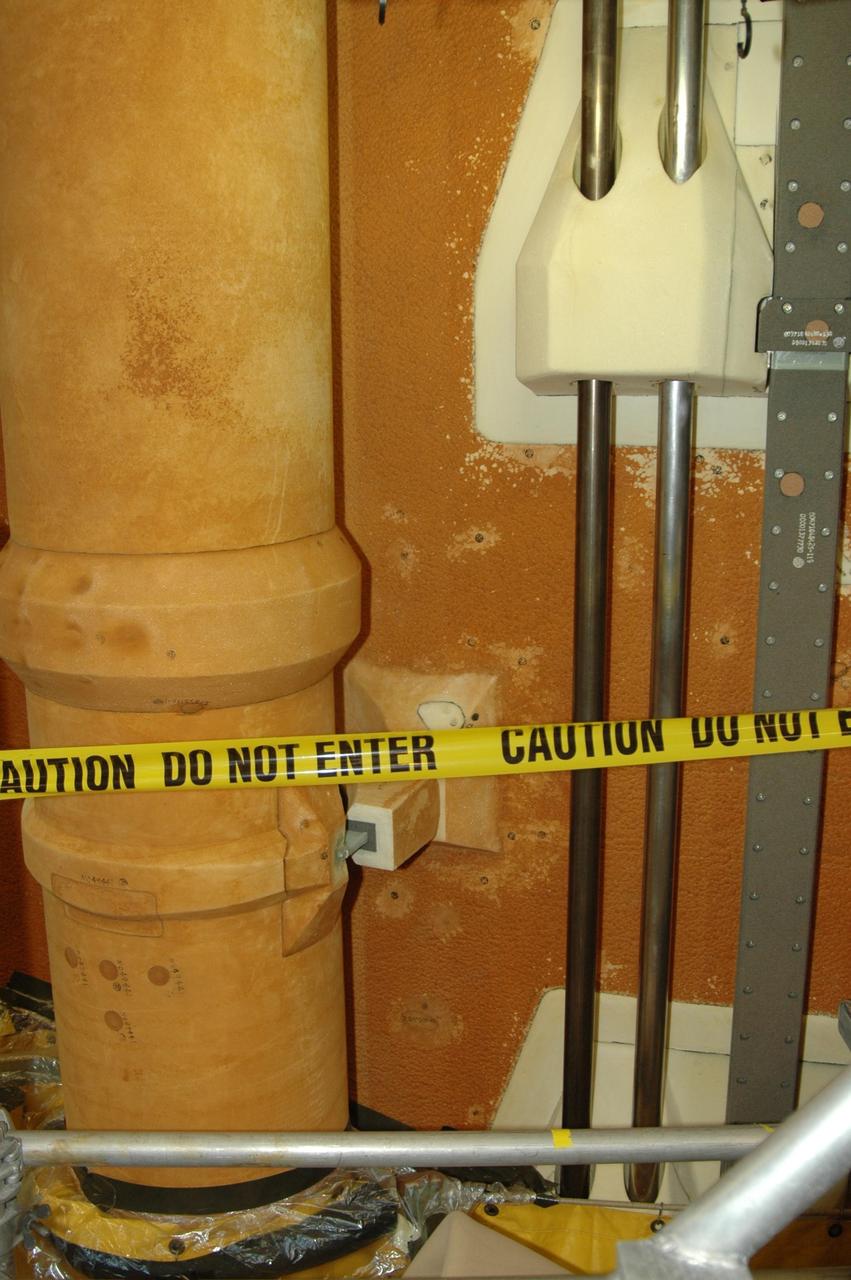
This view shows the pipe (center top) leading toward Endeavour from the side of the White Room at Launch Pad 39B. A loose bracket observed hanging down from the pipe delayed loading of Endeavour's external tank by several hours to allow technicians to remove it. A "U" bolt connects the bracket to a fire suppression water line attached to the exterior of the White Room. The loose bolt could have possibly created a debris hazard
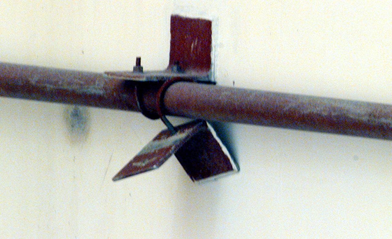
A close-up reveals the loose bracket, observed hanging down from the side of the White Room at Launch Pad 39B, that delayed loading of Endeavour's external tank by several hours to allow technicians to remove it. A "U" bolt connects the bracket to a fire suppression water line attached to the exterior of the White Room. The loose bolt could have possibly created a debris hazard
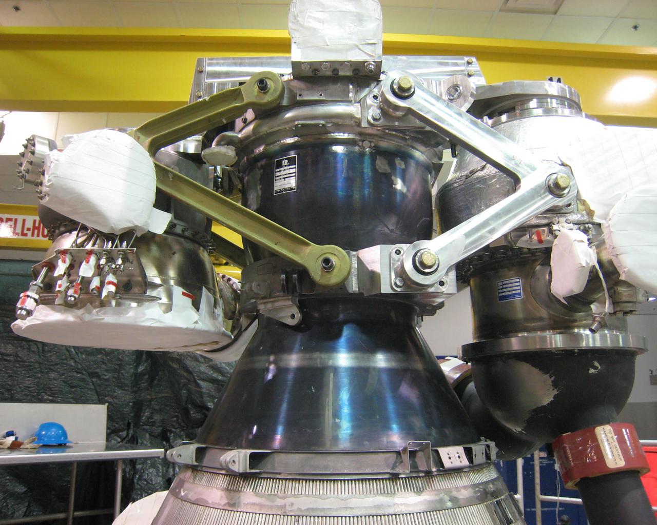
A vintage 1960 J-2 thrust chamber is fitted with brackets and pumps recently at the Pratt & Whitney Rocketdyne assembly facility in Stennis Space Center's Building 9101. Together, the parts comprise the J-2X Powerpack 1A test article. Mississippi Space Services machined the new bracket (the V-shaped arm on the right), making this the first time parts for an engine test article were machined, welded and assembled on site at SSC.
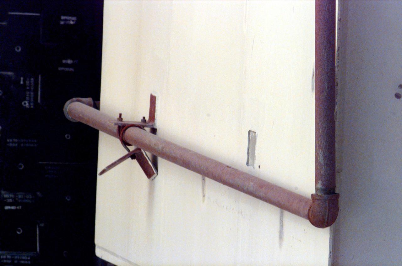
This loose bracket, observed hanging down from the side of the White Room at Launch Pad 39B, delayed loading of Endeavour's external tank by several hours to allow technicians to remove it. A "U" bolt connects the bracket to a fire suppression water line attached to the exterior of the White Room. The loose bolt could have possibly created a debris hazard
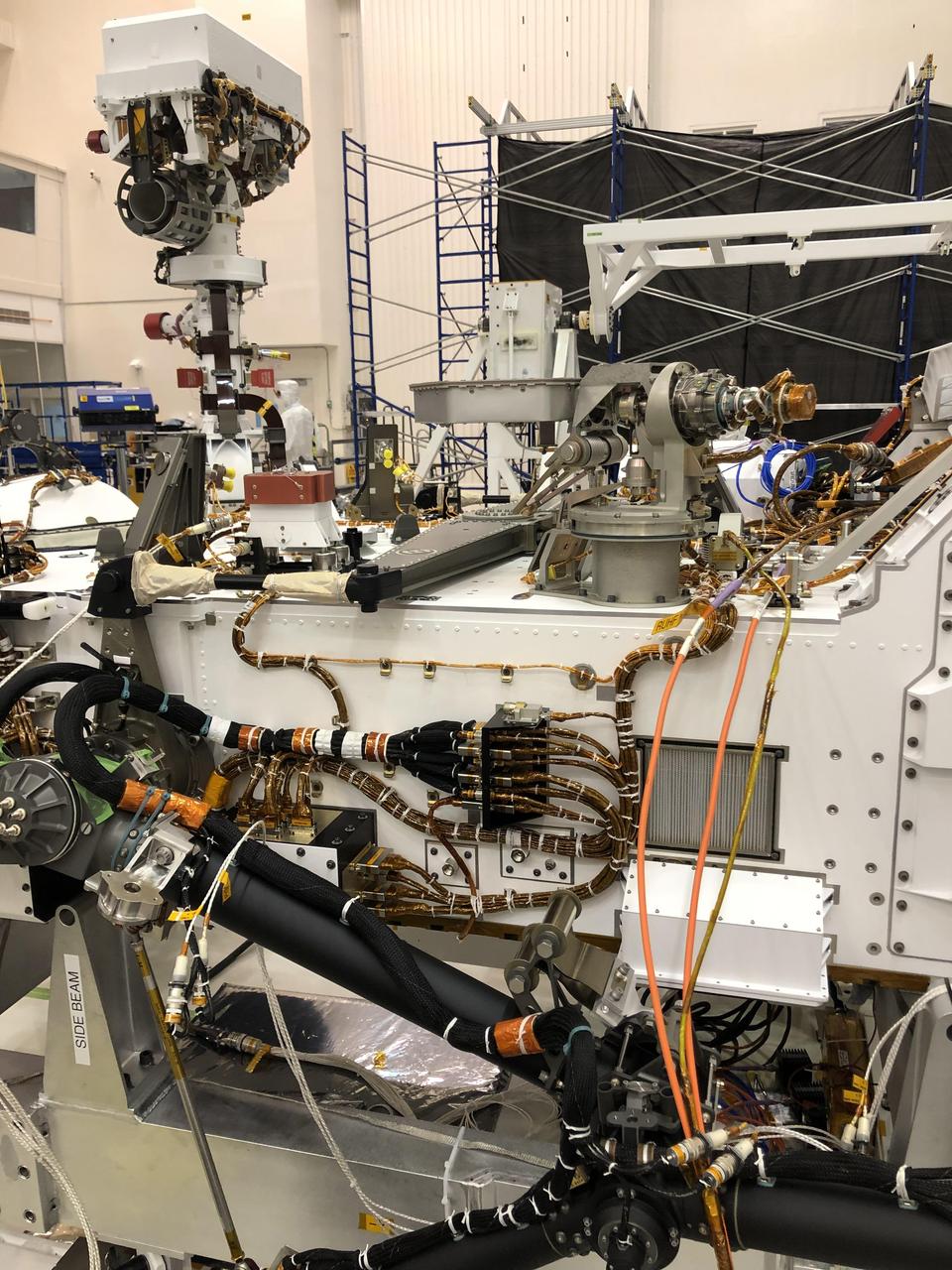
The port side of NASA's Perseverance Mars rover can be seen in this image taken on Nov. 16, 2019, in High Bay 1 of the Spacecraft Assembly Facility at NASA's Jet Propulsion Laboratory in Southern California. At the top left, the rover's remote sensing mast can be seen in the deployed position. To the right of the mast in the center of the image is the light gray high-gain antenna. At center of the image, attached to the side of the rover, is a black cable bracket (with gold cabling running through it). Attached to the top of this black bracket — and gray in color — is the Entry Descent and Landing (EDL) microphone. The rectangular screen to the right of the cable bracket is the rover chassis HEPA filter, which is above the white box housing the Mars Oxygen In-Situ Resource Utilization Experiment (MOXIE) inlet filter assembly. Gray and bright orange cables seen in the foreground of the image belong to ground support equipment. https://photojournal.jpl.nasa.gov/catalog/PIA24045
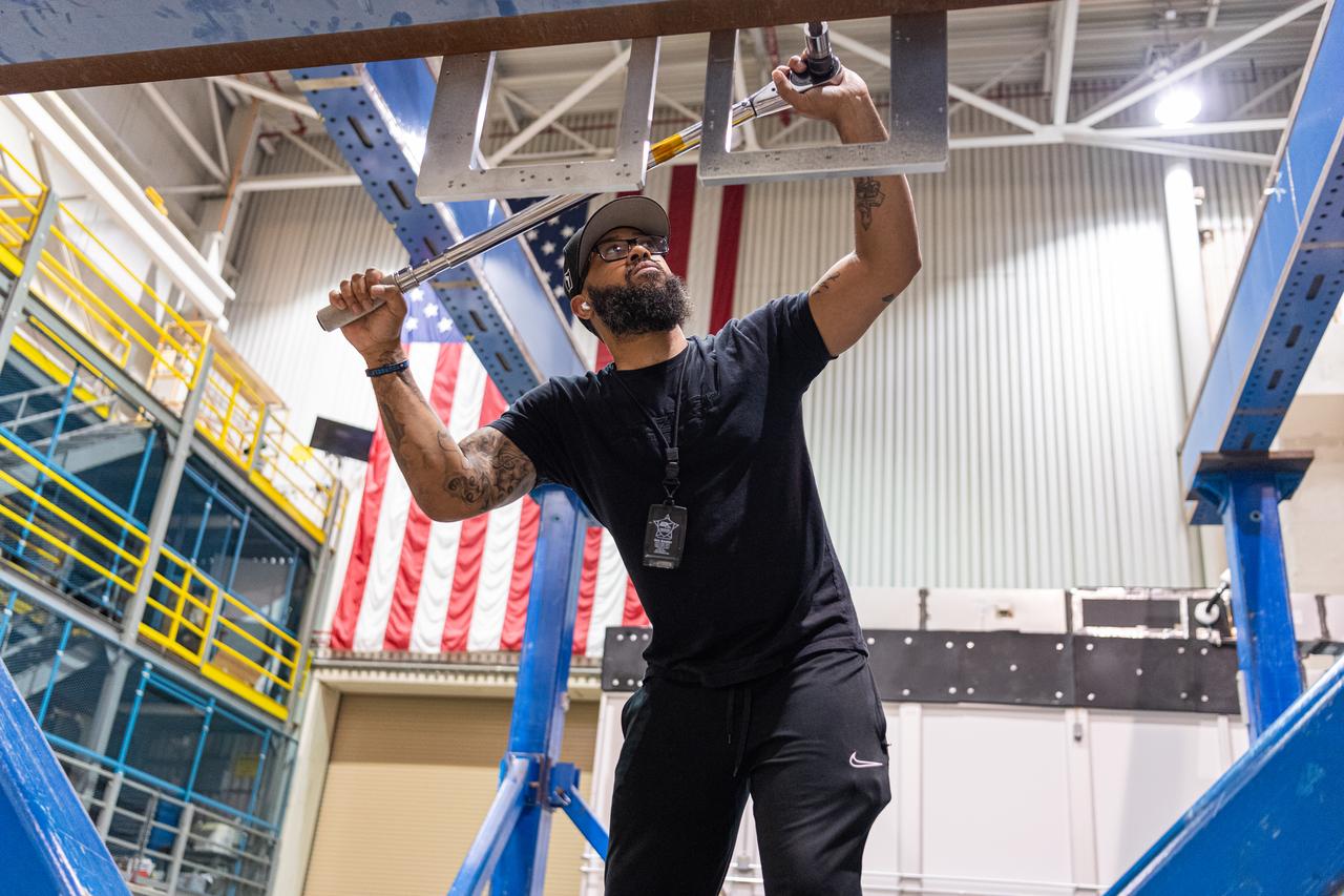
Mechanical engineering and integration technician Ivan Pratt installs brackets onto the static load testing platform in preparation of an OSAM-1 ground support equipment proof test at Goddard Space Flight Center, Greenbelt Md., July 19, 2023. This photo has been reviewed by OSAM1 project management and the Export Control Office and is released for public view. NASA/Mike Guinto
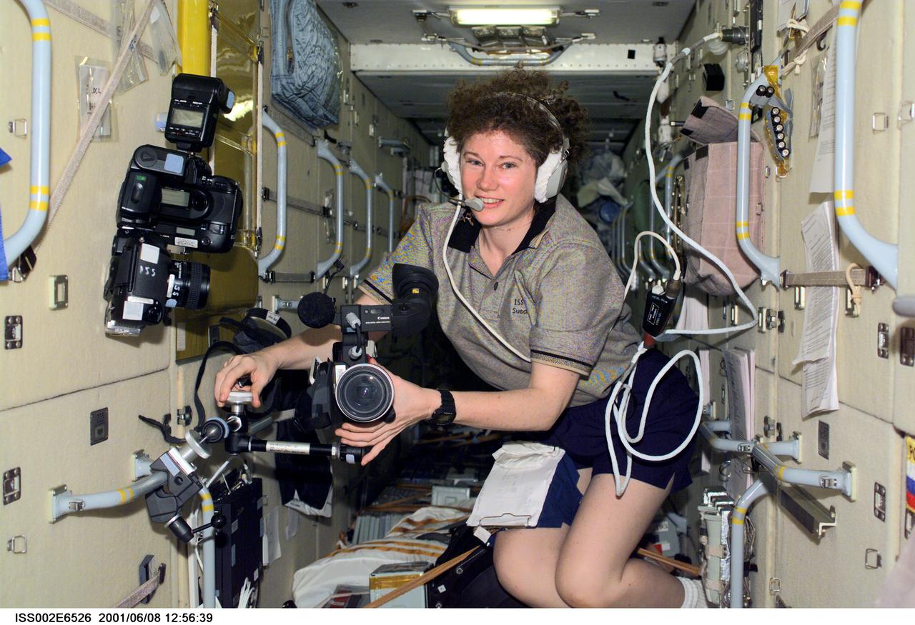
ISS002-E-6526 (8 June 2001) --- Astronaut Susan J. Helms, Expedition Two flight engineer, mounts a video camera onto a bracket in the Zarya or Functional Cargo Block (FGB) of the International Space Station (ISS). The image was recorded with a digital still camera. Alternate NASA ID of 0202499.
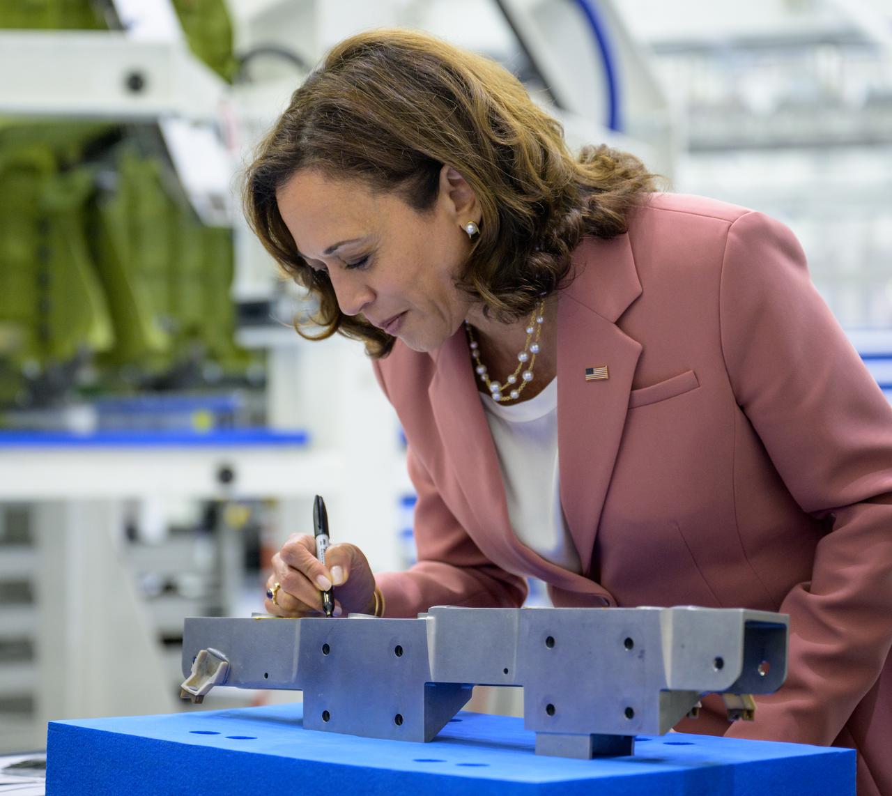
Vice President Kamala Harris signs a Orion spacecraft bracket for the Artemis III mission, Monday, Aug. 29, 2022, at the Neil A. Armstrong Operations and Checkout Building at NASA’s Kennedy Space Center in Florida. Photo Credit: (NASA/Bill Ingalls)
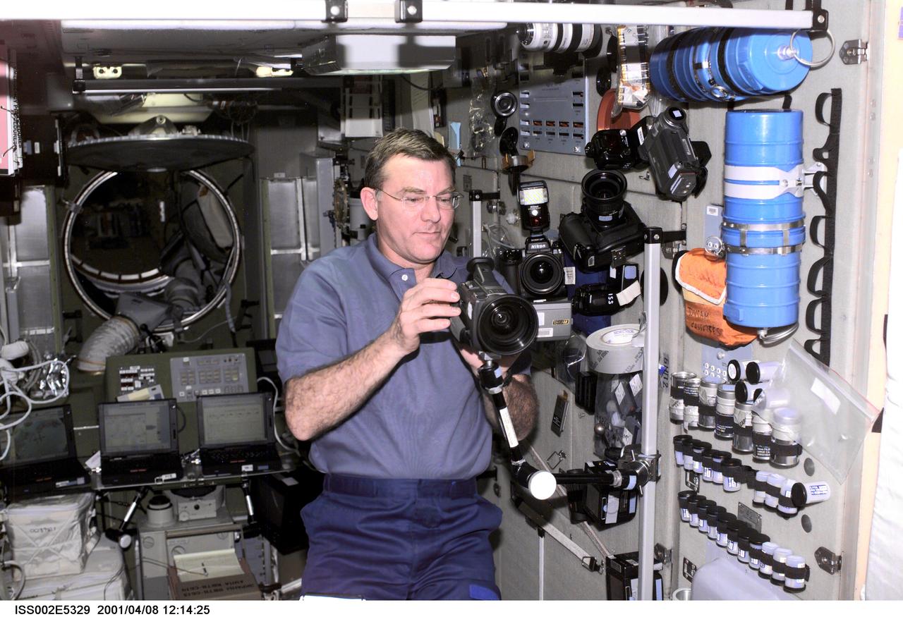
ISS002-E-5329 (08 April 2001) --- Astronaut James S. Voss, Expedition Two flight engineer, sets up a video camera on a mounting bracket in the Zvezda / Service Module of the International Space Station (ISS). A 35mm camera and a digital still camera are also visible nearby. This image was recorded with a digital still camera.
VANDENBERG AIR FORCE BASE, Calif. -- At Vandenberg Air Force Base in California, a technician installs a bracket on a Poly Picosatellite Orbital Deployer, or P-POD, container. The bracket is a connection interface between the P-POD and the Taurus rocket. The P-POD will hold three CubeSats or tiny satellites, designed and created by university and college students that will be carried on the Taurus rocket along with the Glory spacecraft. The Orbital Sciences Corp. Taurus XL rocket will carry NASA's Glory spacecraft into low Earth orbit. Once Glory reaches orbit, it will collect data on the properties of aerosols and black carbon. It also will help scientists understand how the sun's irradiance affects Earth's climate. Launch is scheduled for 5:09 a.m. EST Feb. 23. For information, visit www.nasa.gov/glory. Photo credit: NASA/Randy Beaudoin, VAFB
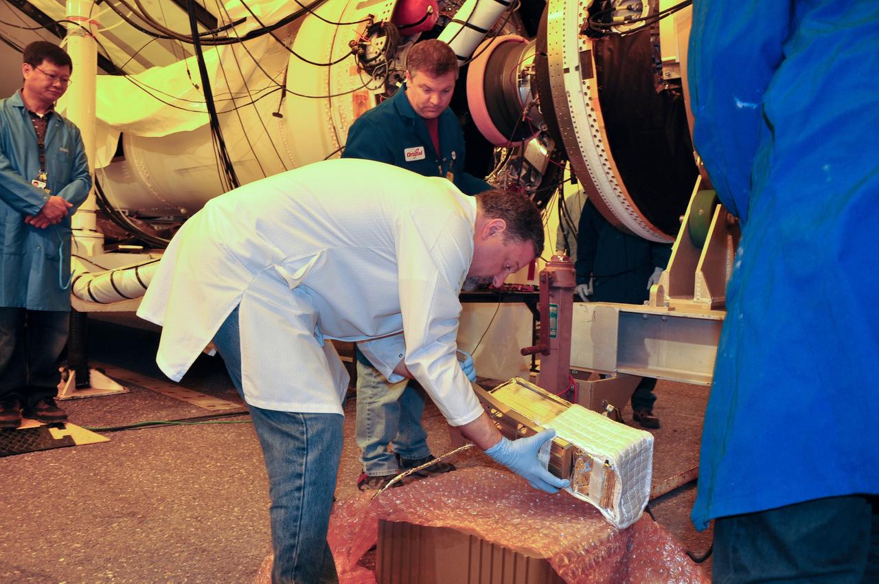
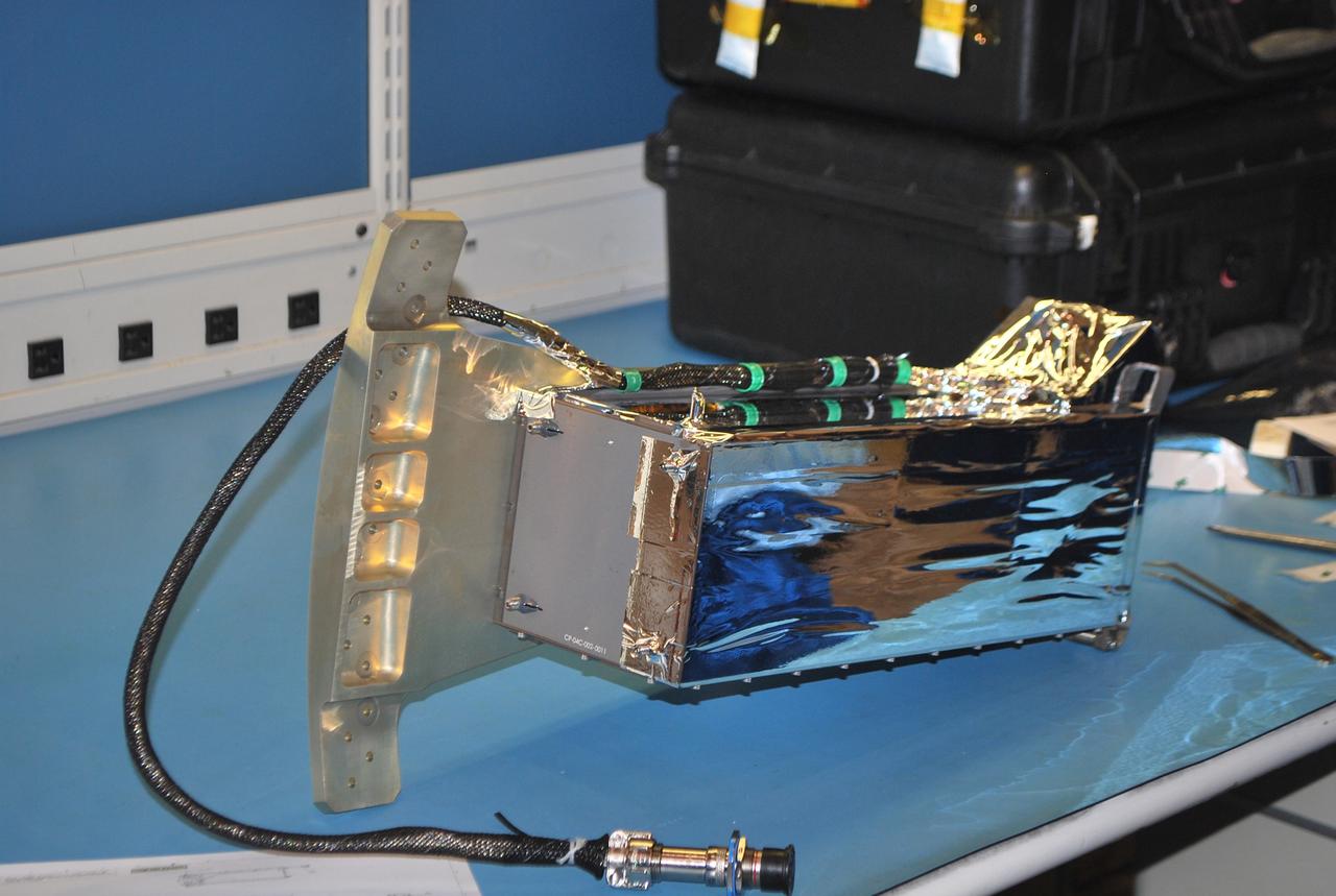
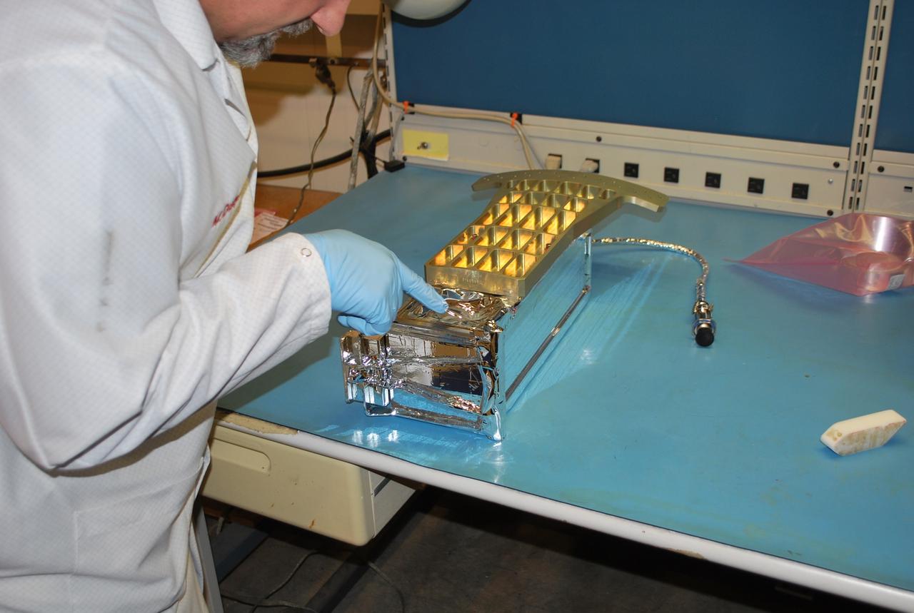
VANDENBERG AIR FORCE BASE, Calif. -- At Space Launch Complex 576-E at Vandenberg Air Force Base in California, a technician lifts the Poly Picosatellite Orbital Deployer, or P-POD, assembly by the Anodized gold aluminum bracket interface. The bracket is the connection point between the P-POD and the aft end of the Taurus rocket's third stage. The P-POD holds three CubeSats or tiny satellites, designed and created by university and college students that will be carried on the Taurus rocket along with the Glory spacecraft. The Orbital Sciences Corp. Taurus XL rocket will carry Glory into low Earth orbit. Once Glory reaches orbit, it will collect data on the properties of aerosols and black carbon. It also will help scientists understand how the sun's irradiance affects Earth's climate. Launch is scheduled for 5:09 a.m. EST Feb. 23. For information, visit www.nasa.gov/glory. Photo credit: NASA/Randy Beaudoin, VAFB
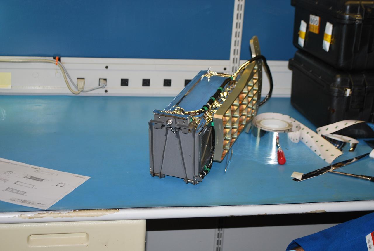
VANDENBERG AIR FORCE BASE, Calif. -- At Vandenberg Air Force Base in California, a Poly Picosatellite Orbital Deployer, or P-POD, container is imaged here with the bracket interface installed. The bracket is a connection interface between the P-POD and the Taurus rocket. The P-POD will hold three CubeSats or tiny satellites, designed and created by university and college students that will be carried on the Taurus rocket along with the Glory spacecraft. The Orbital Sciences Corp. Taurus XL rocket will carry NASA's Glory spacecraft into low Earth orbit. Once Glory reaches orbit, it will collect data on the properties of aerosols and black carbon. It also will help scientists understand how the sun's irradiance affects Earth's climate. Launch is scheduled for 5:09 a.m. EST Feb. 23. For information, visit www.nasa.gov/glory. Photo credit: NASA/Randy Beaudoin,VAFB
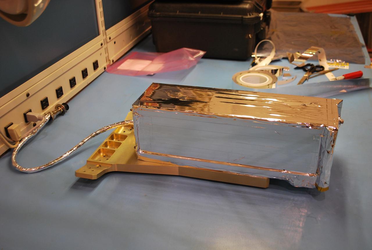
VANDENBERG AIR FORCE BASE, Calif. -- At Vandenberg Air Force Base in California, a Poly Picosatellite Orbital Deployer, or P-POD, container is imaged here after a sheet of thermal insulation has been applied and the bracket interface installed. The bracket will serve as a connection interface between the P-POD and the Taurus rocket. The P-POD will hold three CubeSats or tiny satellites, designed and created by university and college students that will be carried on the Taurus rocket along with the Glory spacecraft. The Orbital Sciences Corp. Taurus XL rocket will carry NASA's Glory spacecraft into low Earth orbit. Once Glory reaches orbit, it will collect data on the properties of aerosols and black carbon. It also will help scientists understand how the sun's irradiance affects Earth's climate. Launch is scheduled for 5:09 a.m. EST Feb. 23. For information, visit www.nasa.gov/glory. Photo credit: NASA/Randy Beaudoin, VAFB
VANDENBERG AIR FORCE BASE, Calif. -- At Vandenberg Air Force Base in California, a Poly Picosatellite Orbital Deployer, or P-POD, container is imaged here with the bracket interface installed. The bracket is a connection interface between the P-POD and the Taurus rocket. The P-POD will hold three CubeSats or tiny satellites, designed and created by university and college students that will be carried on the Taurus rocket along with the Glory spacecraft. The Orbital Sciences Corp. Taurus XL rocket will carry NASA's Glory spacecraft into low Earth orbit. Once Glory reaches orbit, it will collect data on the properties of aerosols and black carbon. It also will help scientists understand how the sun's irradiance affects Earth's climate. Launch is scheduled for 5:09 a.m. EST Feb. 23. For information, visit www.nasa.gov/glory. Photo credit: NASA/Randy Beaudoin, VAFB
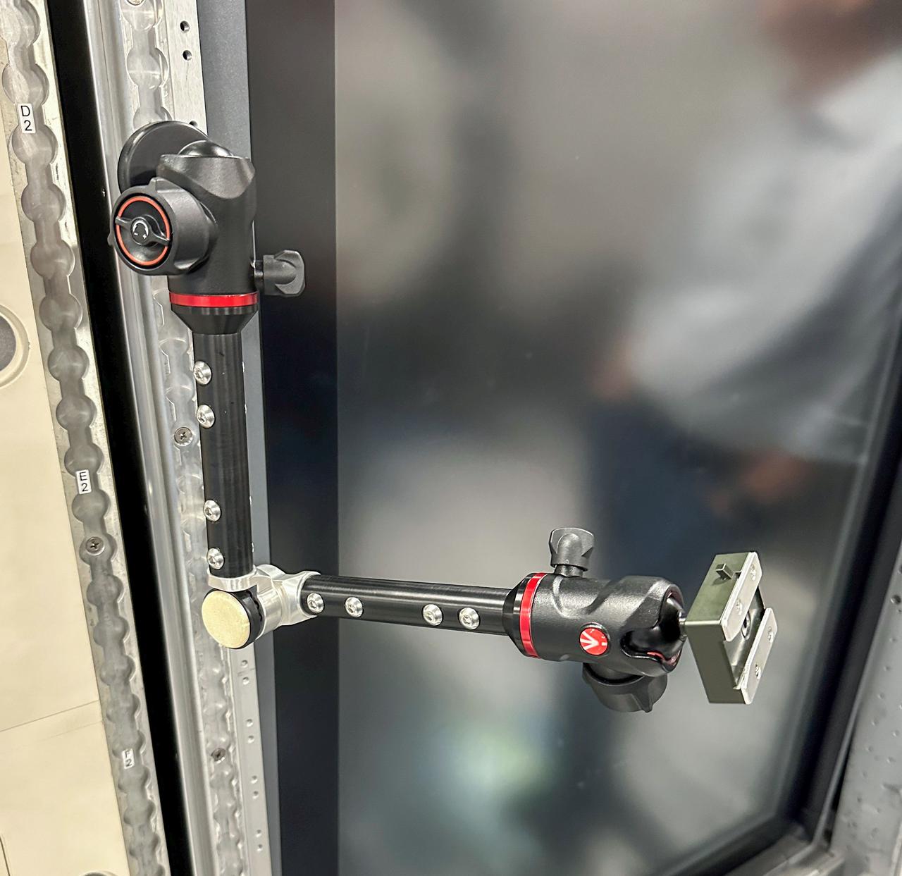
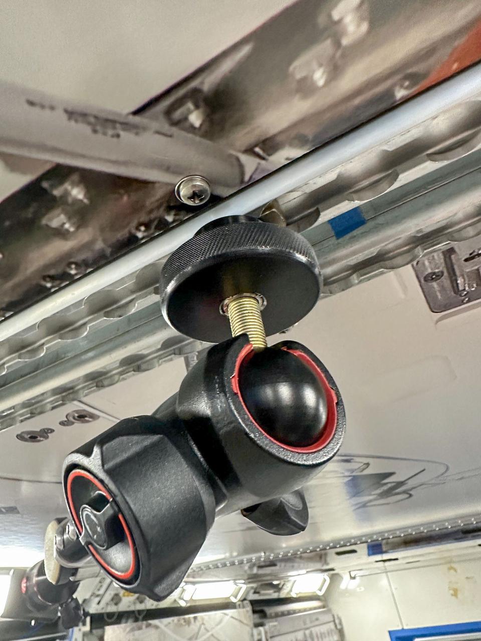
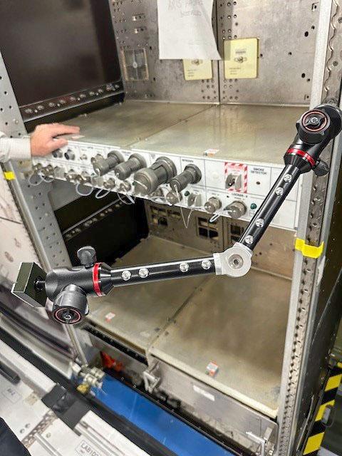
jsc2025e047414 (5/27/2025) --- The High school Students United with NASA to Create Hardware (HUNCH) has designed a device to replace Bogen arms aboard the International Space Station. The HUNCH Utility Bracket (HUB) can be attached to frames and rails and can hold cameras, iPads, and other equipment. The HUB has a jointed design that allows ample range of movement and flexibility. This device aims to aid crew members with tasks such as recording videos and holding iPads to increase efficiency of operations aboard space station. (Image courtesy of HUNCH)
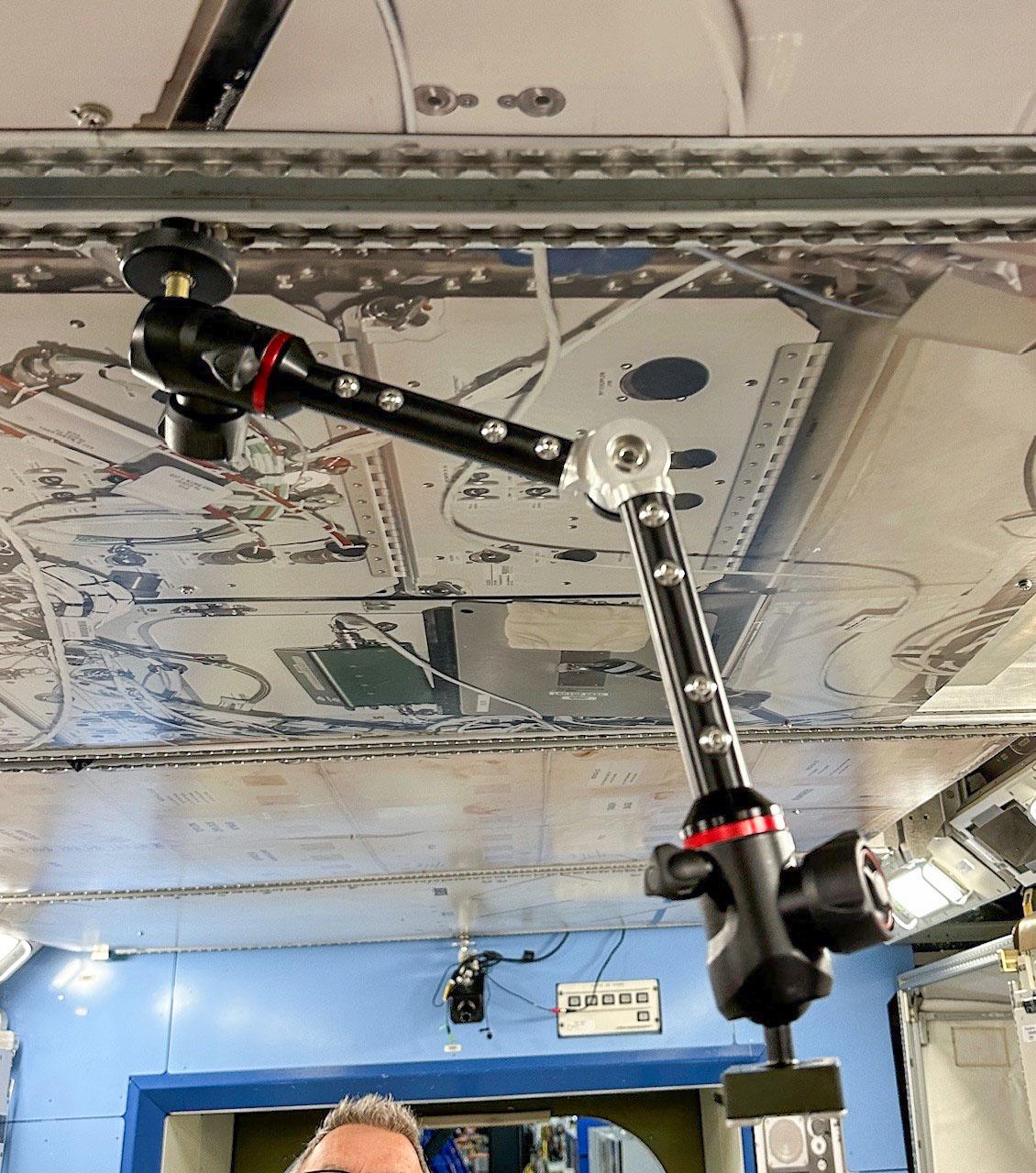
jsc2025e047412 (5/27/2025) --- The High school Students United with NASA to Create Hardware (HUNCH) has designed a device to replace Bogen arms aboard the International Space Station. The HUNCH Utility Bracket (HUB) can be attached to frames and rails and can hold cameras, iPads, and other equipment. The HUB has a jointed design that allows ample range of movement and flexibility. This device aims to aid crew members with tasks such as recording videos and holding iPads to increase efficiency of operations aboard space station. (Image courtesy of HUNCH)
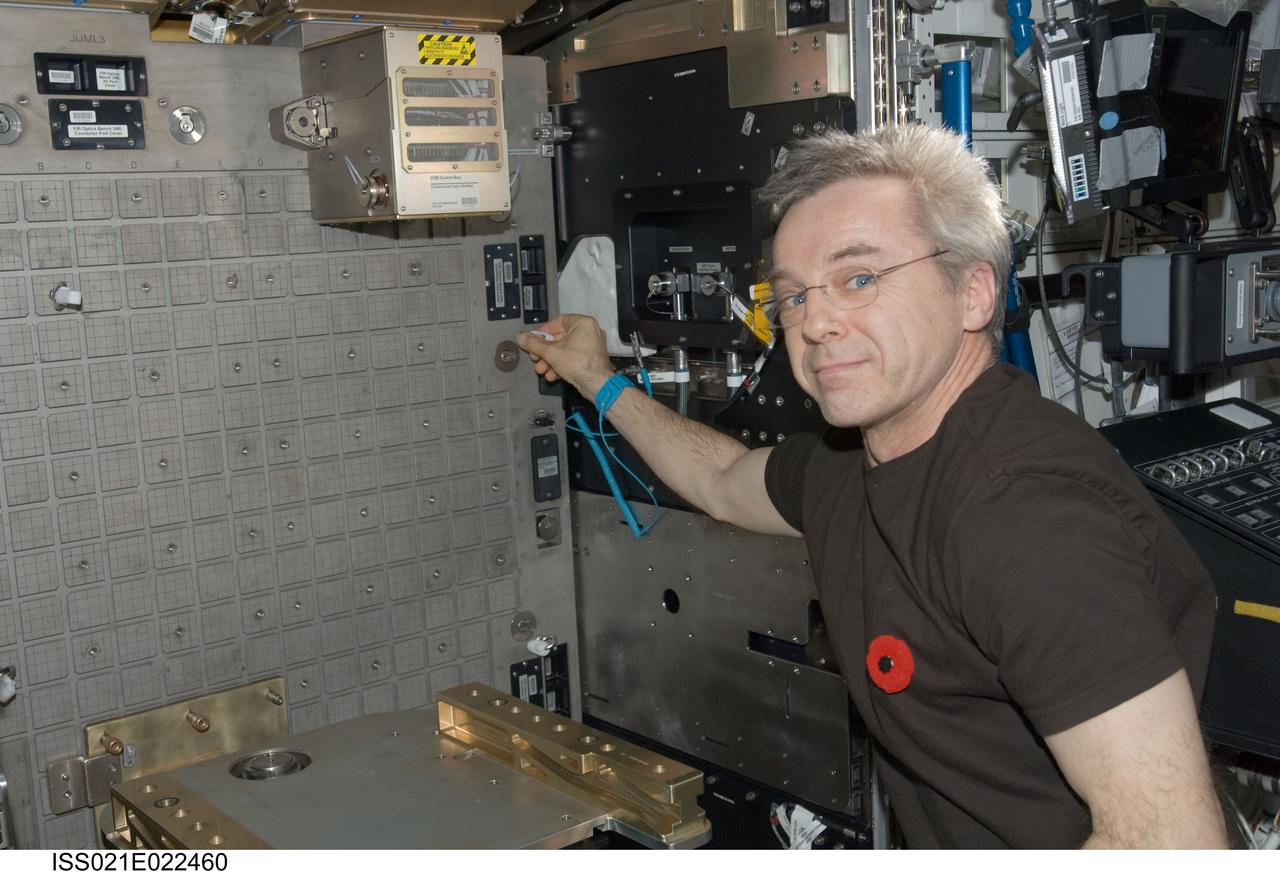
ISS021-E-022460 (9 Nov. 2009) --- Canadian Space Agency astronaut Robert Thirsk, Expedition 21 flight engineer, installs the Light Microscopy Module (LMM) Spindle Bracket Assembly in the Fluids Integrated Rack (FIR) in the Destiny laboratory of the International Space Station. NASA astronaut Nicole Stott (out of frame), flight engineer, assisted Thirsk.
iss072e391307 (Dec. 17, 2024) --- NASA astronaut and Expedition 72 Flight Engineer Nick Hague demonstrates the range of motion and stability of student-designed space hardware aboard the International Space Station's Destiny laboratory module. Hague was testing the HUNCH (High school students United with NASA to Create Hardware) Utility Bracket for its ability to hold and position cameras, computer tablets, and other tools astronauts use daily.
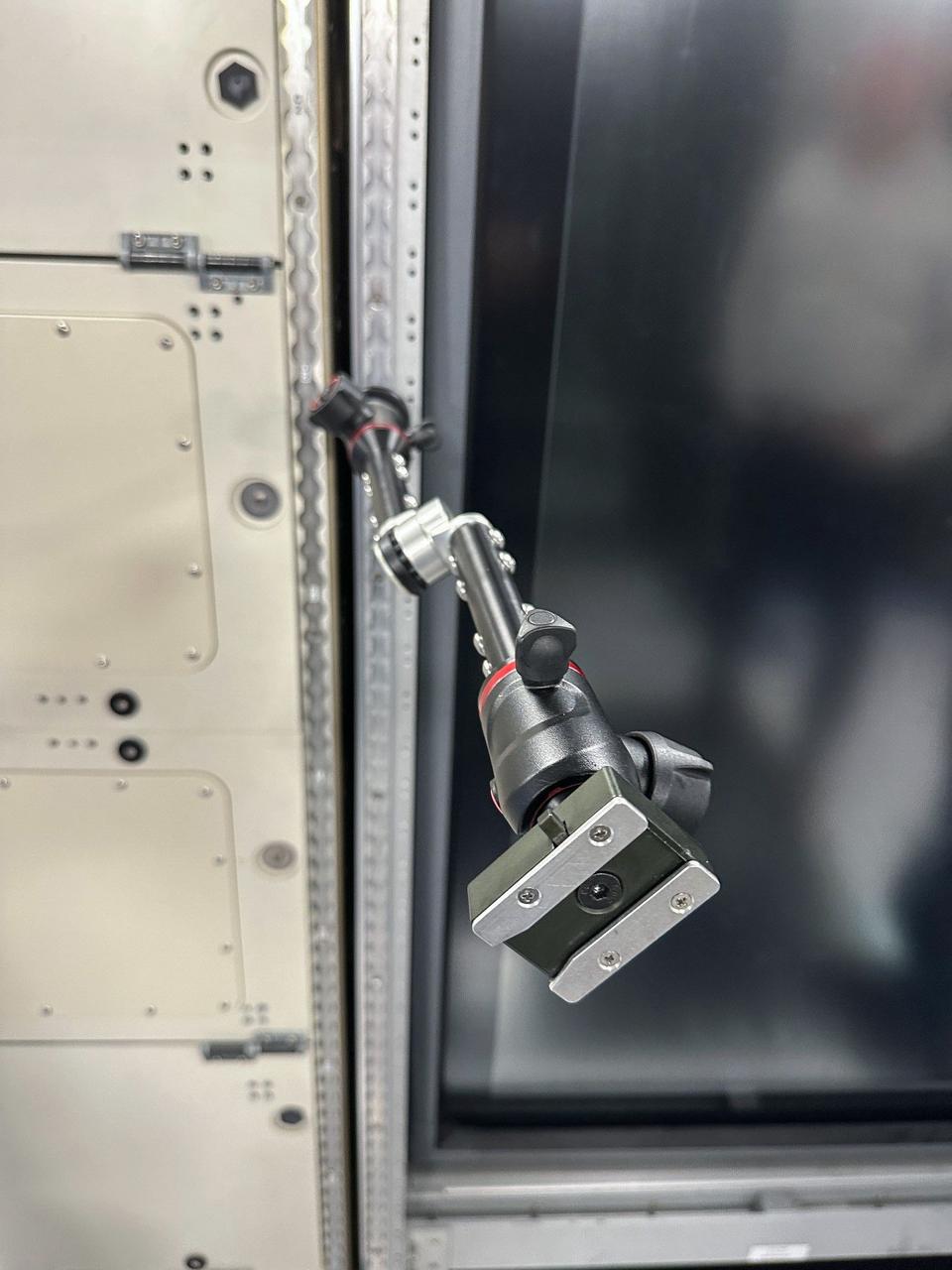
jsc2025e047413 (5/27/2025) --- The High school Students United with NASA to Create Hardware (HUNCH) has designed a device to replace Bogen arms aboard the International Space Station. The HUNCH Utility Bracket (HUB) can be attached to frames and rails and can hold cameras, iPads, and other equipment. The HUB has a jointed design that allows ample range of movement and flexibility. This device aims to aid crew members with tasks such as recording videos and holding iPads to increase efficiency of operations aboard space station. (Image courtesy of HUNCH)
iss072e391290 (Dec. 17, 2024) --- NASA astronaut and Expedition 72 Flight Engineer Nick Hague demonstrates the range of motion and stability of student-designed space hardware aboard the International Space Station's Destiny laboratory module. Hague was testing the HUNCH (High school students United with NASA to Create Hardware) Utility Bracket for its ability to hold and position cameras, computer tablets, and other tools astronauts use daily.
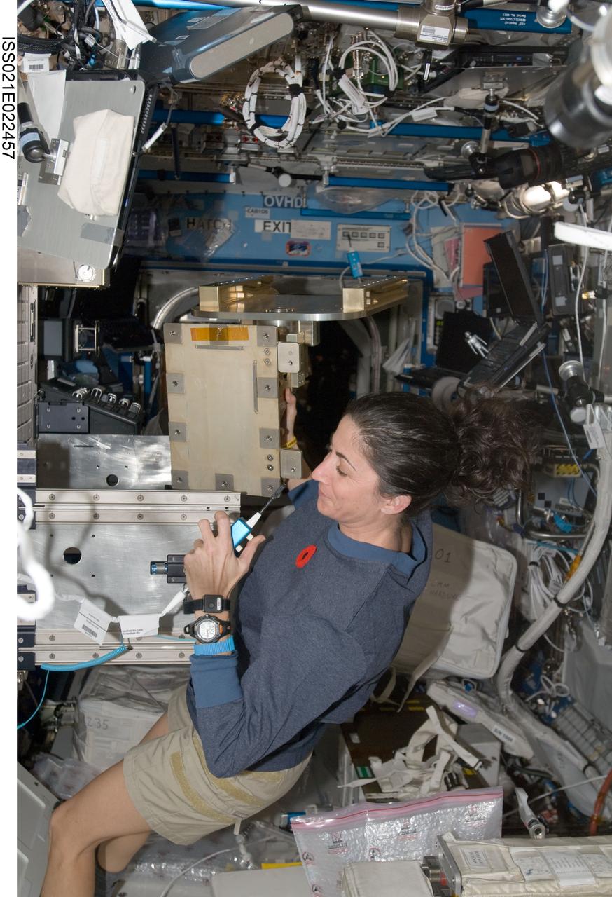
ISS021-E-022457 (9 Nov. 2009) --- NASA astronaut Nicole Stott, Expedition 21 flight engineer, uses a communication system while installing the Light Microscopy Module (LMM) Spindle Bracket Assembly in the Fluids Integrated Rack (FIR) in the Destiny laboratory of the International Space Station. Canadian Space Agency astronaut Robert Thirsk (out of frame) assisted Stott.

jsc2025e047417 (5/27/2025) --- The High school Students United with NASA to Create Hardware (HUNCH) has designed a device to replace Bogen arms aboard the International Space Station. The HUNCH Utility Bracket (HUB) can be attached to frames and rails and can hold cameras, iPads, and other equipment. The HUB has a jointed design that allows ample range of movement and flexibility. This device aims to aid crew members with tasks such as recording videos and holding iPads to increase efficiency of operations aboard space station. (Image courtesy of HUNCH)
Following the successful installation of mounting brackets, technicians successfully installed the pallet for the eXternal Visibility System, or XVS, onto the X-59 Quiet SuperSonic Technology X-plane, also known as X-59 QueSST. The pallet installation marks an assembly milestone as the first NASA flight systems hardware to be installed onto the vehicle. X-59 will fly to demonstrate the ability to produce quiet thumps at supersonic speeds, instead of the typical, loud sonic booms associated with supersonic flight.
At Launch Pad 17-A, Cape Canaveral Air Force Station, a worker adjusts a bracket around the camera he is attaching to the second stage of the Delta II rocket for the Mars Odyssey launch. The orbiter carries three science instruments THEMIS, the Gamma Ray Spectrometer (GRS), and the Mars Radiation Environment Experiment (MARIE) that will map the mineralogy and morphology of the Martian surface. The Mars Odyssey Orbiter is scheduled for launch on April 7, 2001
jsc2025e047411 (5/27/2025) --- The High school Students United with NASA to Create Hardware (HUNCH) has designed a device to replace Bogen arms aboard the International Space Station. The HUNCH Utility Bracket (HUB) can be attached to frames and rails and can hold cameras, iPads, and other equipment. The HUB has a jointed design that allows ample range of movement and flexibility. This device aims to aid crew members with tasks such as recording videos and holding iPads to increase efficiency of operations aboard space station. (Image courtesy of HUNCH)
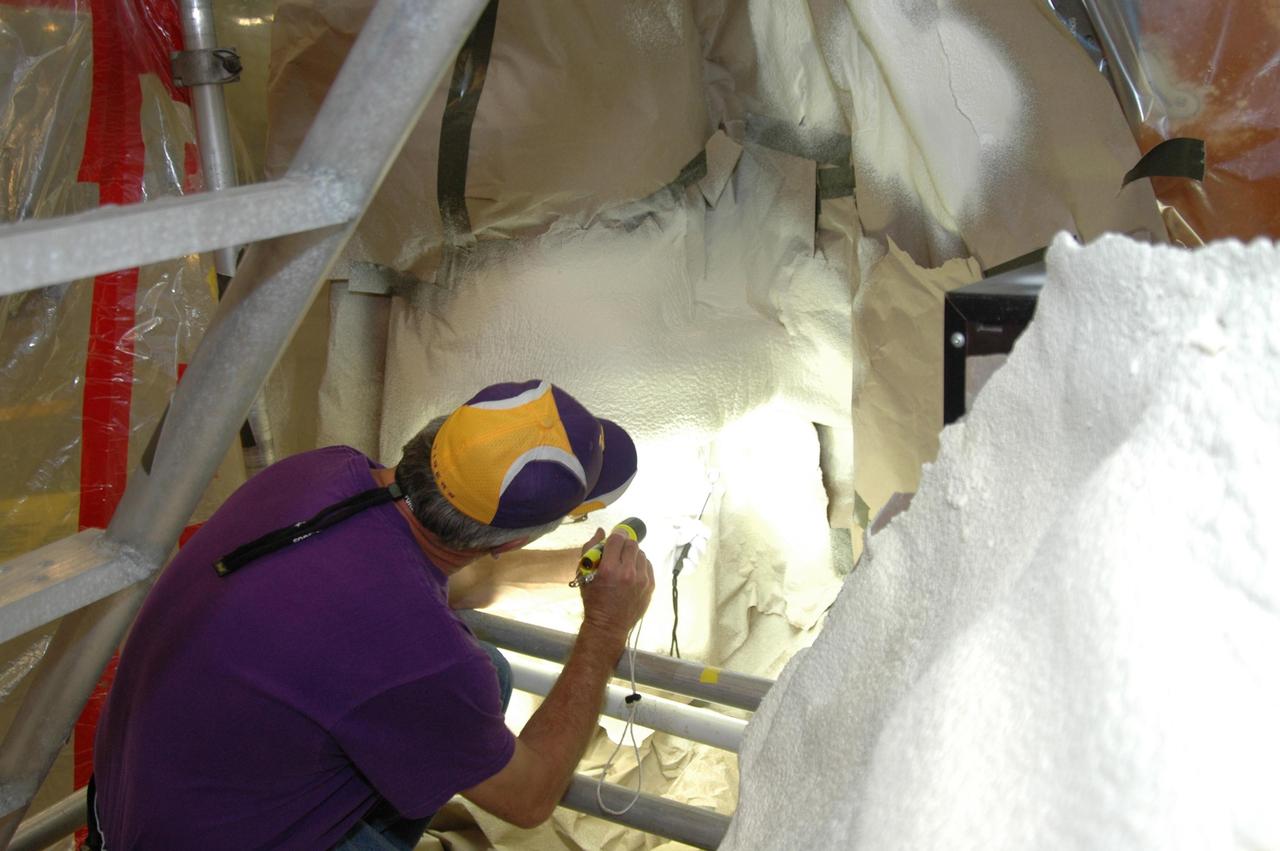
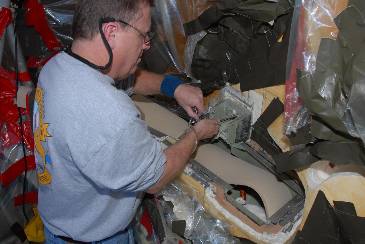
KENNEDY SPACE CENTER, FLA. -- A Lockheed Martin external tank technician from the Michoud Assembly Facility in New Orleans inspects the foam modification on external tank 120 in the Vehicle Assembly Building. The foam insulation and super lightweight ablator cork insulation were removed from the external tank and LO2 feed line bracket on Aug. 24 and replaced only with BX265 foam insulation. The tank is scheduled to fly on Space Shuttle Discovery in October 2007 on mission STS-120. Photo credit: NASA/Jim Grossmann
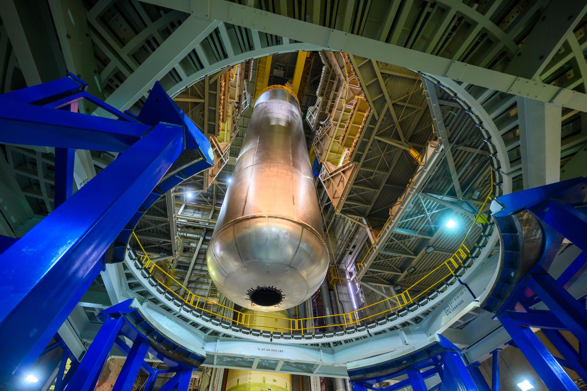
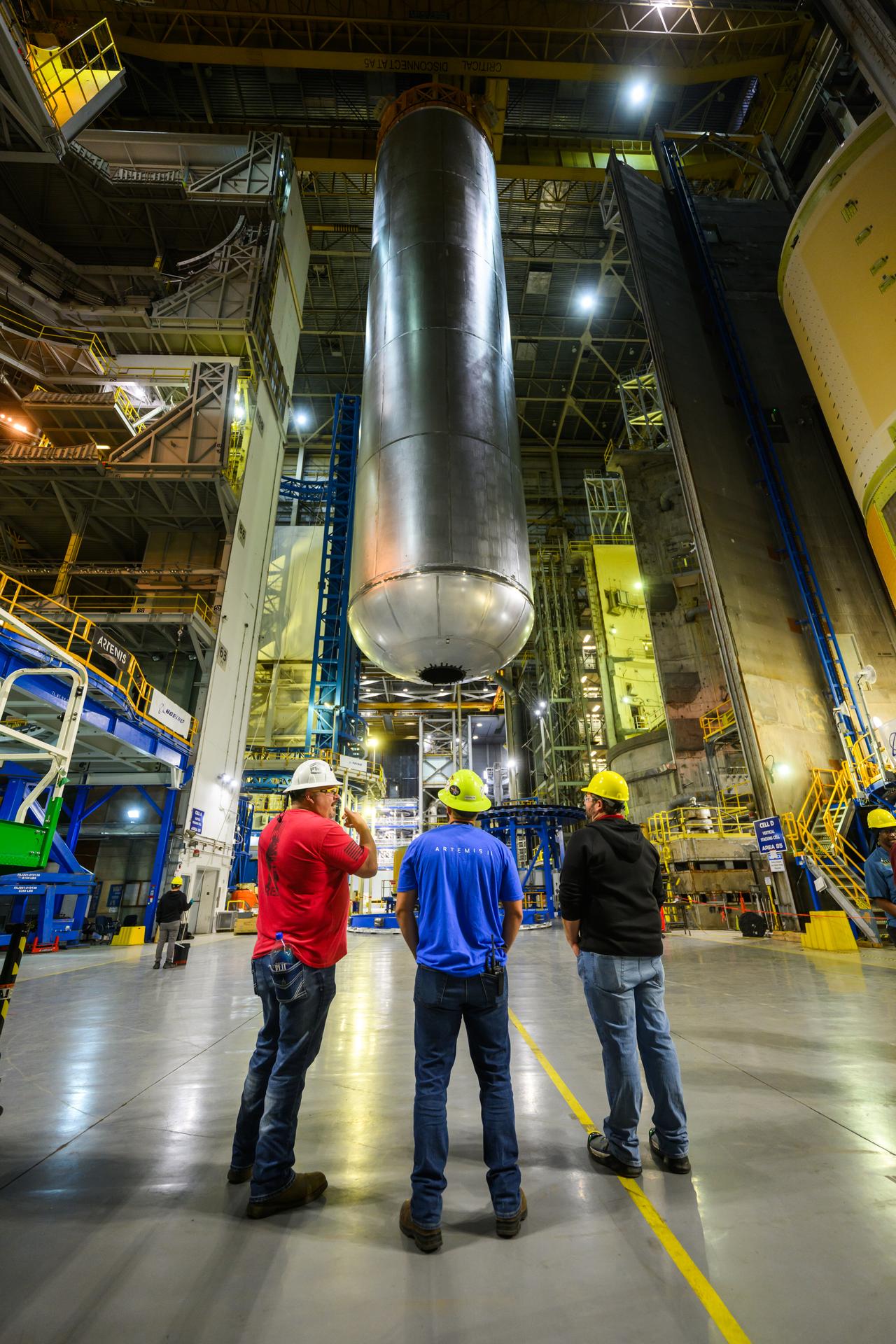
Teams at NASA’s Michoud Assembly Facility in New Orleans lift the 130-foot-tall liquid hydrogen tank off the vertical assembly center on Nov. 14. This is the fourth liquid hydrogen tank manufactured at the facility for the agency’s SLS (Space Launch System) rocket. The completed tank will be loaded into a production cell for technicians to remove the lift tool, perform dimensional scans, and then install brackets, which will allow the move crew to break the tank over from a vertical to a horizontal configuration.
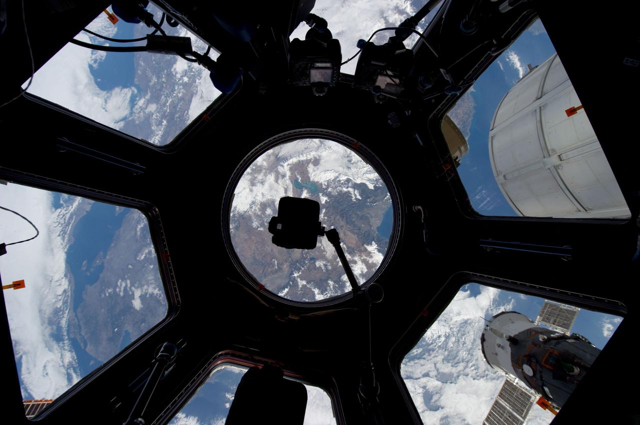
ISS030-E-019300 (29 Dec. 2011) --- This unusual image, photographed through the Cupola on the International Space Station by one of the Expedition 30 crew members, is centered over Turkey. The lake just above the bracket- mounted camera at center is Egirdir Golu, located at 38.05 degrees north latitude and 30.89 degrees east longitude. A Russian Soyuz spacecraft is docked to the station at lower right and part of the Permanent Multipurpose Module(PMM) can be seen just above it.

ISS021-E-022459 (9 Nov. 2009) --- NASA astronaut Nicole Stott, Expedition 21 flight engineer, installs the Light Microscopy Module (LMM) Spindle Bracket Assembly in the Fluids Integrated Rack (FIR) in the Destiny laboratory of the International Space Station. Canadian Space Agency astronaut Robert Thirsk (out of frame) assisted Stott.
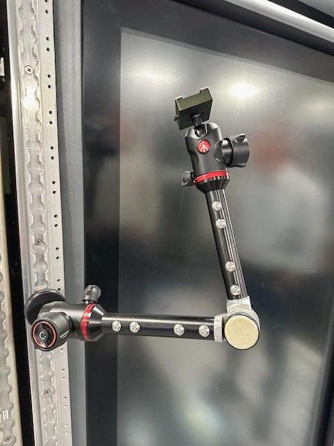
jsc2025e047415 (5/27/2025) --- The High school Students United with NASA to Create Hardware (HUNCH) has designed a device to replace Bogen arms aboard the International Space Station. The HUNCH Utility Bracket (HUB) can be attached to frames and rails and can hold cameras, iPads, and other equipment. The HUB has a jointed design that allows ample range of movement and flexibility. This device aims to aid crew members with tasks such as recording videos and holding iPads to increase efficiency of operations aboard space station. (Image courtesy of HUNCH)
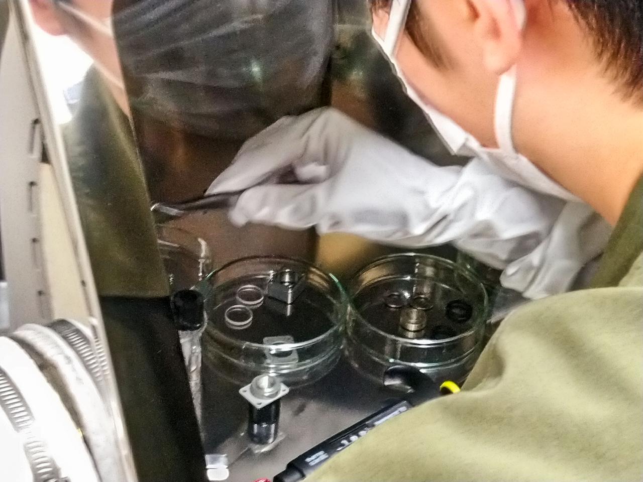
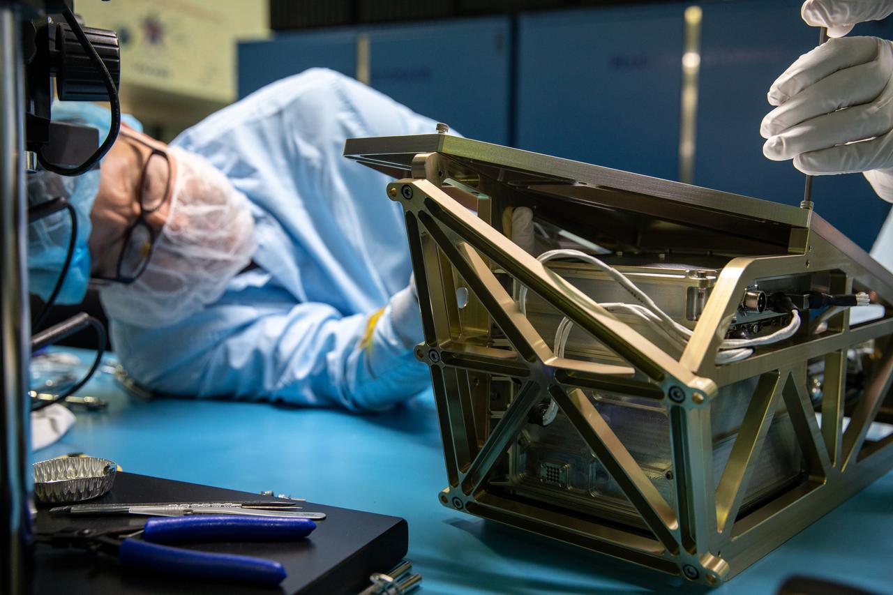
jsc2023e010199 (3/31/2023) --- The exposure unit for the Tanpopo-5 study is assembled under a nitrogen atmosphere for aqueous solution samples. The investigation studies the origin, transportation, and survival of life in space. Radioresistant microbes of Deionococcus radiodurans, sporophytes of the moss Physcomitrium patens, nucleotide precursors, and amino acids are exposed to the space environment for six months using the Exposed Experiment Bracket Attached on i-SEEP (ExBAS) facility. Image courtesy of the Tanpopo Team.
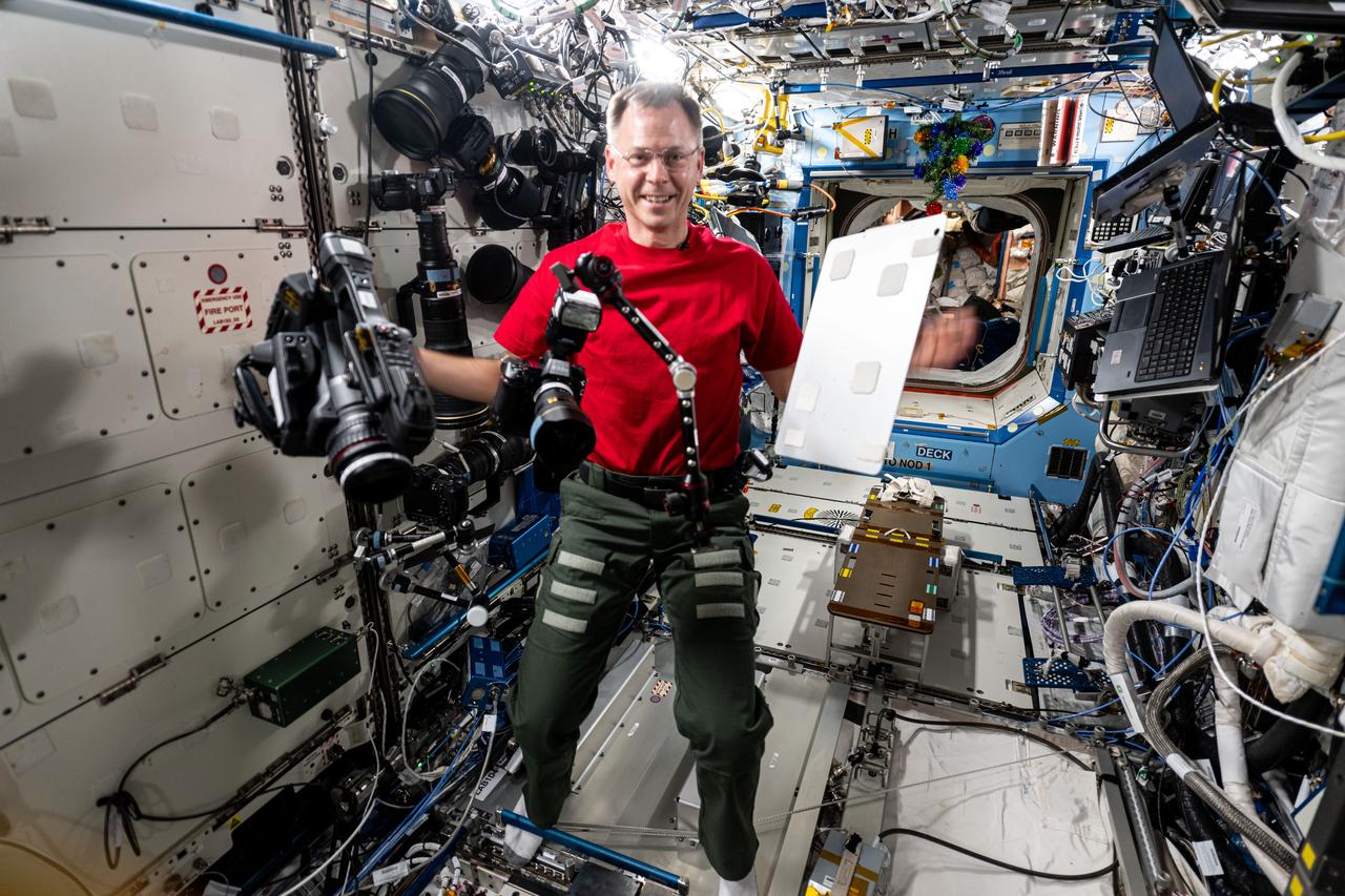
iss072e391353 (Dec. 17, 2024) --- NASA astronaut and Expedition 72 Flight Engineer Nick Hague demonstrates the range of motion and stability of student-designed space hardware aboard the International Space Station's Destiny laboratory module. Hague was testing the HUNCH (High school students United with NASA to Create Hardware) Utility Bracket for its ability to hold and position cameras, computer tablets, and other tools astronauts use daily.
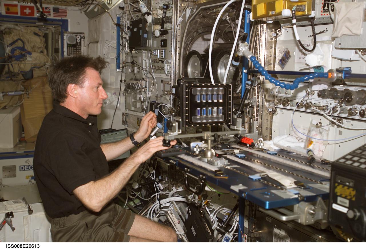
ISS008-E-20613 (5 April 2004) --- Astronaut C. Michael Foale, Expedition 8 commander and NASA ISS science officer, works with a Slow Growth Sample Module (SGSM) for the Binary Colloidal Alloy Test-3 (BCAT) experiment. The SGSM is on a mounting bracket attached to the Maintenance Work Area (MWA) table set up in the Destiny laboratory of the International Space Station (ISS).

At Launch Pad 17-A, Cape Canaveral Air Force Station, a worker adjusts a bracket around the camera he is attaching to the second stage of the Delta II rocket for the Mars Odyssey launch. The orbiter carries three science instruments THEMIS, the Gamma Ray Spectrometer (GRS), and the Mars Radiation Environment Experiment (MARIE) that will map the mineralogy and morphology of the Martian surface. The Mars Odyssey Orbiter is scheduled for launch on April 7, 2001
Following the successful installation of mounting brackets, technicians successfully installed the pallet for the eXternal Visibility System, or XVS, onto the X-59 Quiet SuperSonic Technology X-plane, also known as X-59 QueSST. The pallet installation marks an assembly milestone as the first NASA flight systems hardware to be installed onto the vehicle. X-59 will fly to demonstrate the ability to produce quiet thumps at supersonic speeds, instead of the typical, loud sonic booms associated with supersonic flight.
jsc2025e047418 (5/27/2025) --- The High school Students United with NASA to Create Hardware (HUNCH) has designed a device to replace Bogen arms aboard the International Space Station. The HUNCH Utility Bracket (HUB) can be attached to frames and rails and can hold cameras, iPads, and other equipment. The HUB has a jointed design that allows ample range of movement and flexibility. This device aims to aid crew members with tasks such as recording videos and holding iPads to increase efficiency of operations aboard space station. (Image courtesy of HUNCH)
Teams at NASA’s Michoud Assembly Facility in New Orleans lift the 130-foot-tall liquid hydrogen tank off the vertical assembly center on Nov. 14. This is the fourth liquid hydrogen tank manufactured at the facility for the agency’s SLS (Space Launch System) rocket. The completed tank will be loaded into a production cell for technicians to remove the lift tool, perform dimensional scans, and then install brackets, which will allow the move crew to break the tank over from a vertical to a horizontal configuration.
ISS008-E-20610 (5 April 2004) --- Astronaut C. Michael Foale, Expedition 8 commander and NASA ISS science officer, uses a digital still camera to photograph a Slow Growth Sample Module (SGSM) for the Binary Colloidal Alloy Test-3 (BCAT) experiment. The SGSM is on a mounting bracket attached to the Maintenance Work Area (MWA) table set up in the Destiny laboratory of the International Space Station (ISS).
VANDENBERG AIR FORCE BASE, Calif. -- At Vandenberg Air Force Base in California, a technician is pointing to a vent hole in the Poly Picosatellite Orbital Deployer , or P-POD, assembly after a sheet of silver reflective tape to protect it from the sun had been applied and the bracket interface installed. The bracket will serve as a connection interface between the P-POD and the aft end of the Taurus rocket's third stage. The P-POD will hold three CubeSats or tiny satellites, designed and created by university and college students that will be carried on the Taurus rocket along with the Glory spacecraft. The Orbital Sciences Corp. Taurus XL rocket will carry NASA's Glory spacecraft into low Earth orbit. Once Glory reaches orbit, it will collect data on the properties of aerosols and black carbon. It also will help scientists understand how the sun's irradiance affects Earth's climate. Launch is scheduled for 5:09 a.m. EST Feb. 23. For information, visit www.nasa.gov/glory. Photo credit: NASA/Randy Beaudoin, VAFB
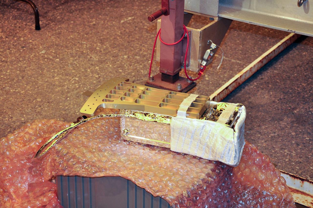
VANDENBERG AIR FORCE BASE, Calif. -- At Space Launch Complex 576-E at Vandenberg Air Force Base in California, the Poly Picosatellite Orbital Deployer, or P-POD, assembly is imaged wrapped in its thermal insulation blanket and sheeting and the attached Anodized gold aluminum bracket interface. The bracket is the connection point between the P-POD and the aft end of the Taurus rocket's third stage. The P-POD holds three CubeSats or tiny satellites, designed and created by university and college students that will be carried on the Taurus rocket along with the Glory spacecraft. The Orbital Sciences Corp. Taurus XL rocket will carry Glory into low Earth orbit. Once Glory reaches orbit, it will collect data on the properties of aerosols and black carbon. It also will help scientists understand how the sun's irradiance affects Earth's climate. Launch is scheduled for 5:09 a.m. EST Feb. 23. For information, visit www.nasa.gov/glory. Photo credit: NASA/Randy Beaudoin, VAFB
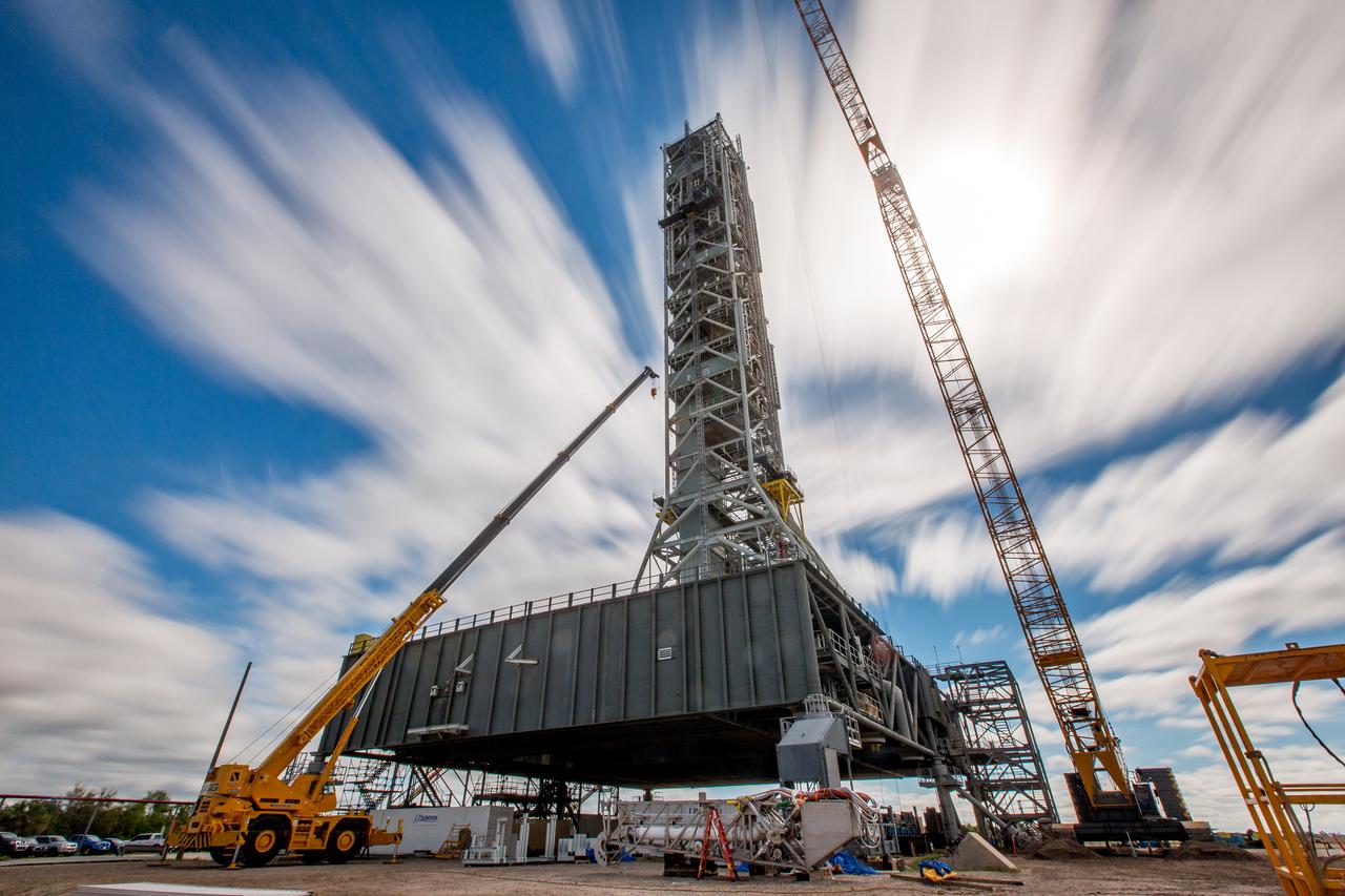
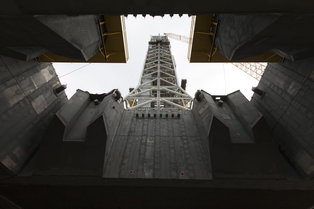
A long-exposure view of the mobile launcher at NASA's Kennedy Space Center in Florida. Cranes and rigging are being used to lift the bracket for the Orion Service Module Umbilical (OSMU) up for installation on the mobile launcher tower. The tower will be equipped with a number of lines, called umbilicals, that will connect to the Space Launch System rocket and Orion spacecraft for Exploration Mission-1 (EM-1). The OSMU will be located high on the mobile launcher tower and, prior to launch, will transfer liquid coolant for the electronics and air for the Environmental Control System to the Orion service module that houses these critical systems to support the spacecraft. EM-1 is scheduled to launch in 2018. The Ground Systems Development and Operations Program is overseeing installation of the umbilicals.
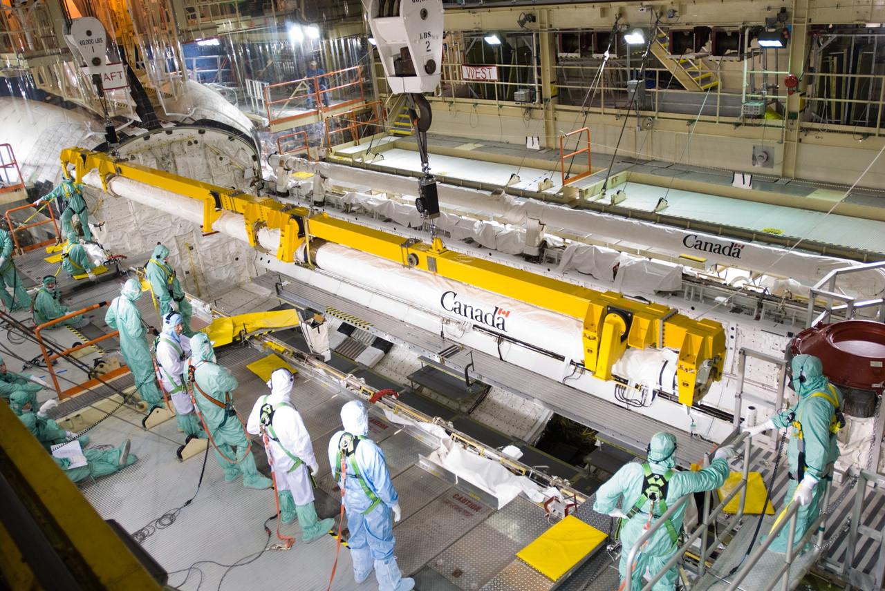
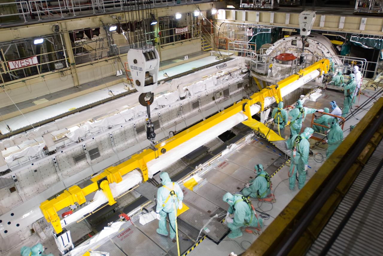
KENNEDY SPACE CENTER, FLA. - In the Orbiter Processing Facility's bay 1, workers prepare the orbiter boom sensor system for installation on the starboard side of Atlantis's payload bay for mission STS-117. The 50-foot-long boom attaches to the shuttle arm and provides equipment to inspect the shuttle's heat shield while in space. It contains an intensified television camera (ITVC) and a laser dynamic range imager, which are mounted on a pan and tilt unit, and a laser camera system (LCS) mounted on a stationary bracket. Mission STS-117 will carry the S3/S4 arrays for installation on the International Space Station. Launch of Space Shuttle Atlantis is scheduled for March. Photo credit: NASA/Jack Pfaller
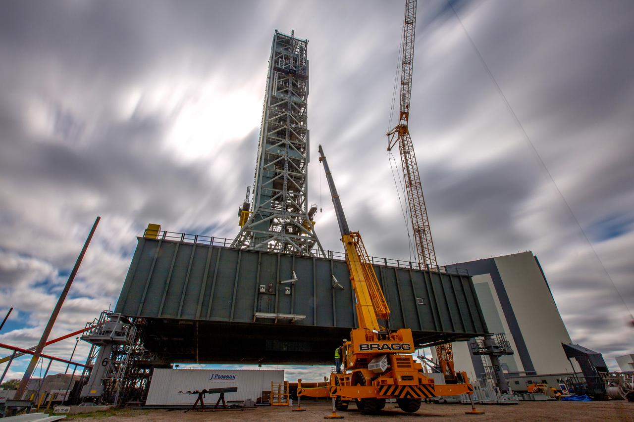
A long-exposure view of the mobile launcher at NASA's Kennedy Space Center in Florida. Cranes and rigging are being used to lift the bracket for the Orion Service Module Umbilical (OSMU) up for installation on the mobile launcher tower. The tower will be equipped with a number of lines, called umbilicals, that will connect to the Space Launch System rocket and Orion spacecraft for Exploration Mission-1 (EM-1). The OSMU will be located high on the mobile launcher tower and, prior to launch, will transfer liquid coolant for the electronics and air for the Environmental Control System to the Orion service module that houses these critical systems to support the spacecraft. EM-1 is scheduled to launch in 2018. The Ground Systems Development and Operations Program is overseeing installation of the umbilicals.
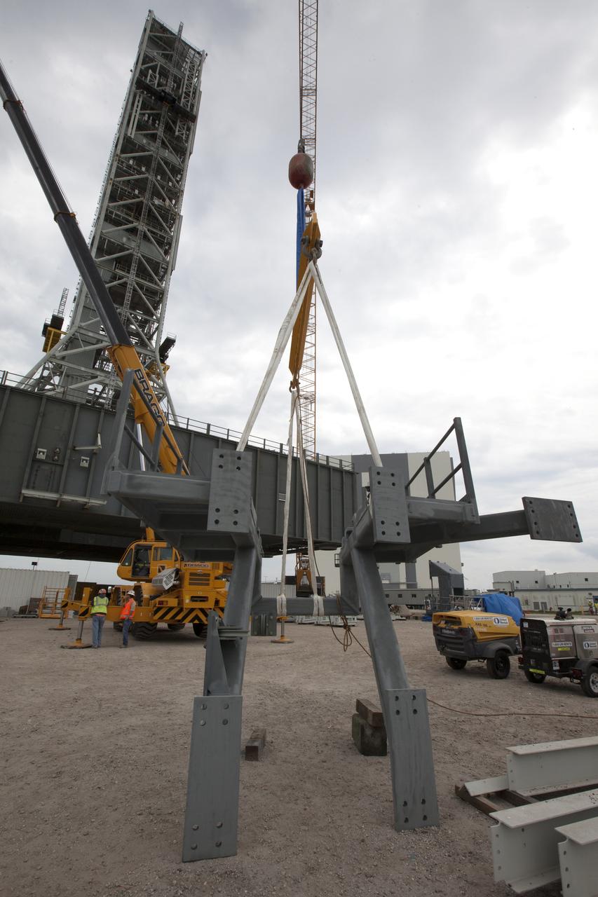
Preparations are underway to lift the bracket for the Orion Service Module Umbilical (OSMU) up for installation on the mobile launcher tower at NASA's Kennedy Space Center in Florida. The mobile launcher tower will be equipped with a number of lines, called umbilicals, that will connect to the Space Launch System rocket and Orion spacecraft for Exploration Mission-1 (EM-1). The OSMU will be located high on the mobile launcher tower and, prior to launch, will transfer liquid coolant for the electronics and air for the Environmental Control System to the Orion service module that houses these critical systems to support the spacecraft. EM-1 is scheduled to launch in 2018. The Ground Systems Development and Operations Program is overseeing installation of the umbilicals.
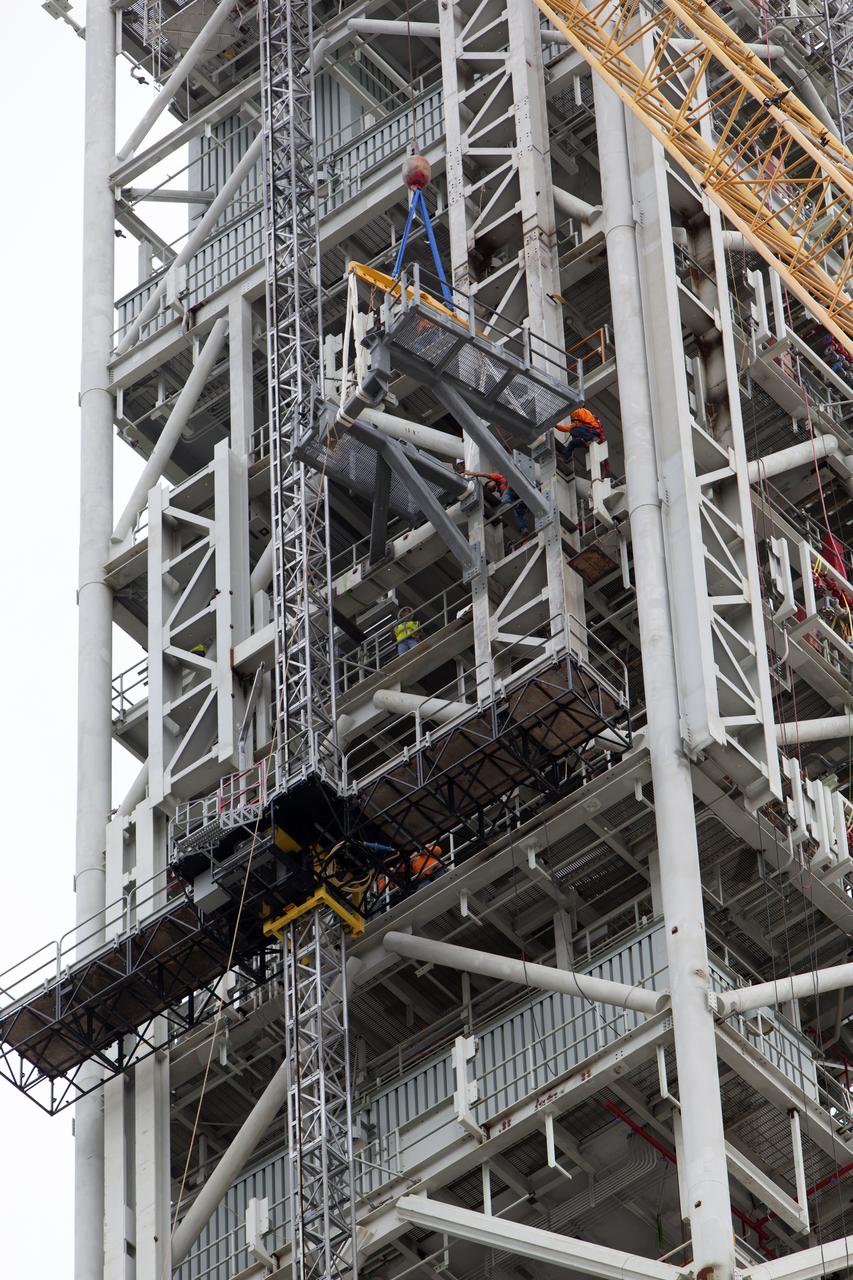
A crane positions the bracket for the Orion Service Module Umbilical (OSMU) for installation on the mobile launcher tower at NASA's Kennedy Space Center in Florida. The mobile launcher tower will be equipped with a number of lines, called umbilicals, that will connect to the Space Launch System rocket and Orion spacecraft for Exploration Mission-1 (EM-1). The OSMU will be located high on the mobile launcher tower and, prior to launch, will transfer liquid coolant for the electronics and air for the Environmental Control System to the Orion service module that houses these critical systems to support the spacecraft. EM-1 is scheduled to launch in 2018. The Ground Systems Development and Operations Program is overseeing installation of the umbilicals.
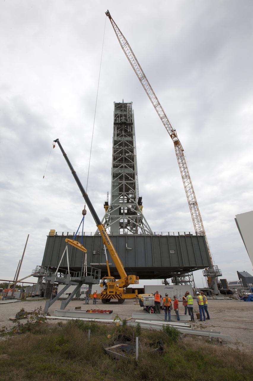
Preparations are underway to lift the bracket for the Orion Service Module Umbilical (OSMU) up for installation on the mobile launcher tower at NASA's Kennedy Space Center in Florida. The mobile launcher tower will be equipped with a number of lines, called umbilicals, that will connect to the Space Launch System rocket and Orion spacecraft for Exploration Mission-1 (EM-1). The OSMU will be located high on the mobile launcher tower and, prior to launch, will transfer liquid coolant for the electronics and air for the Environmental Control System to the Orion service module that houses these critical systems to support the spacecraft. EM-1 is scheduled to launch in 2018. The Ground Systems Development and Operations Program is overseeing installation of the umbilicals.
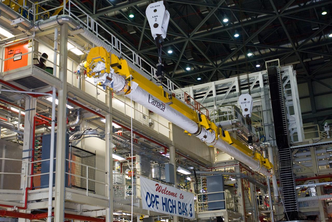
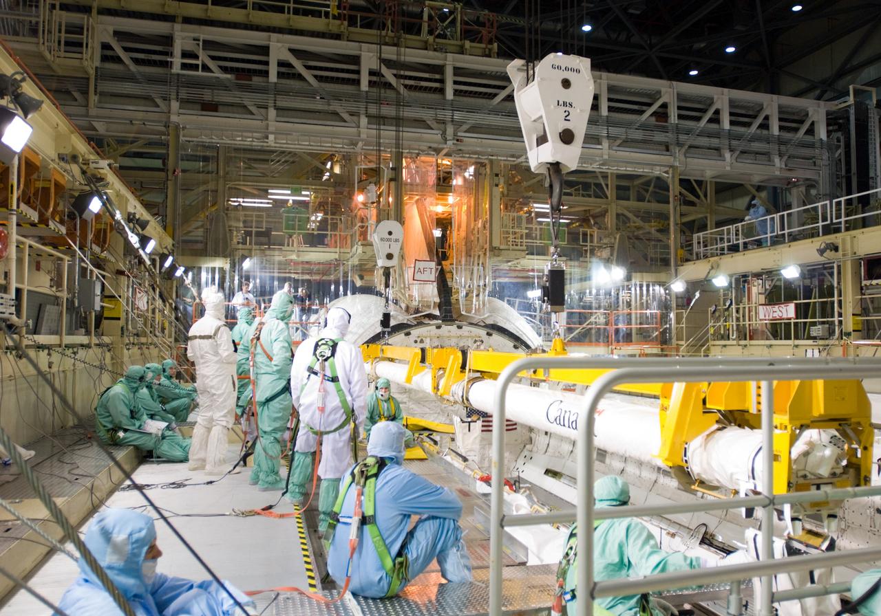
CAPE CANAVERAL, Fla. – In the Orbiter Processing Facility’s bay 3, the orbiter boom sensor system is lifted by a crane for installation in space shuttle Discovery’s payload bay for mission STS-128. The 50-foot-long boom attaches to the shuttle arm and provides equipment to inspect the shuttle's heat shield while in space. It contains an intensified television camera (ITVC) and a laser dynamic range imager, which are mounted on a pan and tilt unit, and a laser camera system (LCS) mounted on a stationary bracket. The STS-128 flight will carry science and storage racks to the International Space Station on space shuttle Discovery. Launch of Discovery is targeted for Aug. 6. Photo credit: NASA/Jim Grossmann
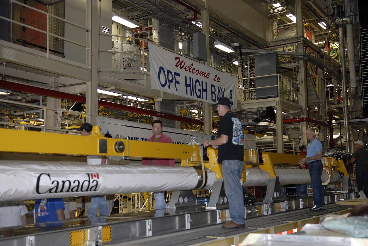
CAPE CANAVERAL, Fla. – In the Orbiter Processing Facility’s bay 3, workers prepare to install the orbiter boom sensor system in the payload bay of space shuttle Discovery to support mission STS-128. The 50-foot-long boom attaches to the shuttle arm and provides equipment to inspect the shuttle's heat shield while in space. It contains an intensified television camera (ITVC) and a laser dynamic range imager, which are mounted on a pan and tilt unit, and a laser camera system (LCS) mounted on a stationary bracket. The STS-128 flight will carry science and storage racks to the International Space Station on space shuttle Discovery. Launch of Discovery is targeted for Aug. 6. Photo credit: NASA/Kim Shiflett
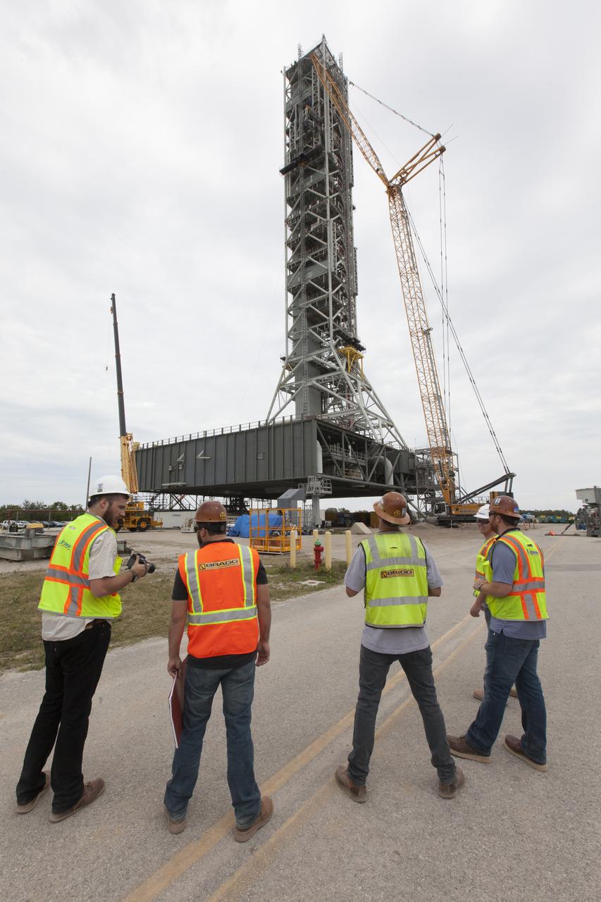
Crane specialists monitor the progress as the bracket for the Orion Service Module Umbilical (OSMU) is lifted high up for installation on the mobile launcher tower at NASA's Kennedy Space Center in Florida. The mobile launcher tower will be equipped with a number of lines, called umbilicals, that will connect to the Space Launch System rocket and Orion spacecraft for Exploration Mission-1 (EM-1). The OSMU will be located high on the mobile launcher tower and, prior to launch, will transfer liquid coolant for the electronics and air for the Environmental Control System to the Orion service module that houses these critical systems to support the spacecraft. EM-1 is scheduled to launch in 2018. The Ground Systems Development and Operations Program is overseeing installation of the umbilicals.
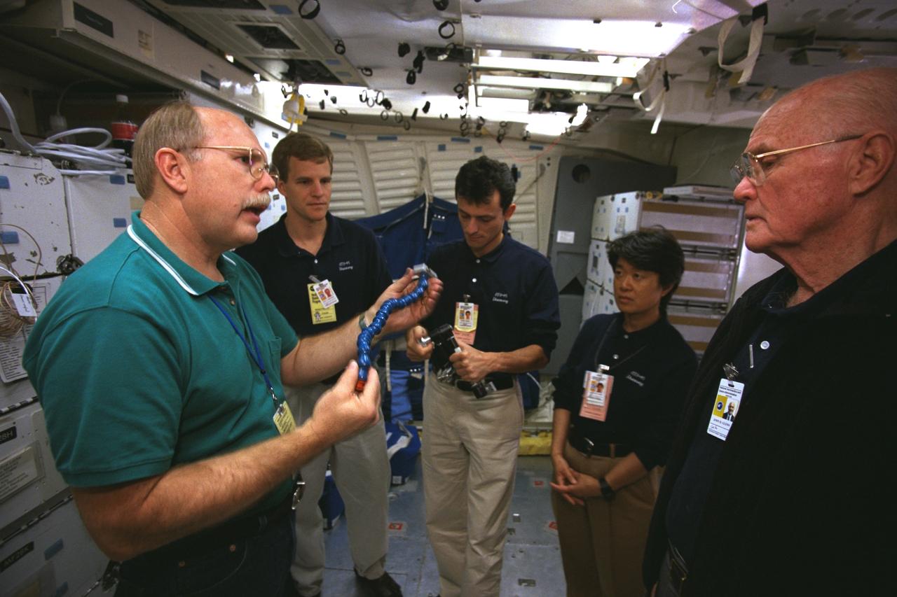
S98-08745 (May 1998) --- Four members of the STS-95 crew are briefed on flight hardware during a training session in the shuttle crew compartment trainer (CCT) at the Johnson Space Center (JSC). Donald C. Carico, an instructor, holds a loc-line bracket. Crewmembers, from the left, are Scott E. Parazynski and Pedro Duque, both mission specialists; Chiaki Mukai and U.S. Sen. John H. Glenn Jr., both payload specialists. Duque represents the European Space Agency (ESA) and Mukai, Japan's National Space Development Agency (NASDA). The photo was taken by Joe McNally, National Geographic, for NASA.
CAPE CANAVERAL, Fla. – In the Orbiter Processing Facility’s bay 3, the orbiter boom sensor system is lowered by a crane into the payload bay of space shuttle Discovery for installation to support mission STS-128. The 50-foot-long boom attaches to the shuttle arm and provides equipment to inspect the shuttle's heat shield while in space. It contains an intensified television camera (ITVC) and a laser dynamic range imager, which are mounted on a pan and tilt unit, and a laser camera system (LCS) mounted on a stationary bracket. The STS-128 flight will carry science and storage racks to the International Space Station on space shuttle Discovery. Launch of Discovery is targeted for Aug. 6. Photo credit: NASA/Jim Grossmann
CAPE CANAVERAL, Fla. – In the Orbiter Processing Facility’s bay 3, workers install the orbiter boom sensor system in the payload bay of space shuttle Discovery to support mission STS-128. The 50-foot-long boom attaches to the shuttle arm and provides equipment to inspect the shuttle's heat shield while in space. It contains an intensified television camera (ITVC) and a laser dynamic range imager, which are mounted on a pan and tilt unit, and a laser camera system (LCS) mounted on a stationary bracket. The STS-128 flight will carry science and storage racks to the International Space Station on space shuttle Discovery. Launch of Discovery is targeted for Aug. 6. Photo credit: NASA/Jim Grossmann
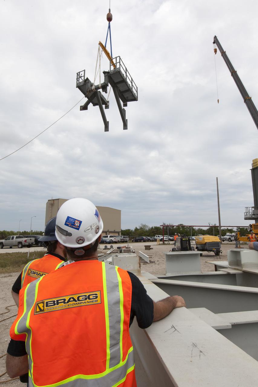
Crane specialists monitor the progress as the bracket for the Orion Service Module Umbilical (OSMU) is lifted up for installation on the mobile launcher tower at NASA's Kennedy Space Center in Florida. The mobile launcher tower will be equipped with a number of lines, called umbilicals, that will connect to the Space Launch System rocket and Orion spacecraft for Exploration Mission-1 (EM-1). The OSMU will be located high on the mobile launcher tower and, prior to launch, will transfer liquid coolant for the electronics and air for the Environmental Control System to the Orion service module that houses these critical systems to support the spacecraft. EM-1 is scheduled to launch in 2018. The Ground Systems Development and Operations Program is overseeing installation of the umbilicals.
In this view looking down from high up on the mobile launcher, a crane positions the bracket for the Orion Service Module Umbilical (OSMU) for installation on the mobile launcher tower at NASA's Kennedy Space Center in Florida. The mobile launcher tower will be equipped with a number of lines, called umbilicals, that will connect to the Space Launch System rocket and Orion spacecraft for Exploration Mission-1 (EM-1). The OSMU will be located high on the mobile launcher tower and, prior to launch, will transfer liquid coolant for the electronics and air for the Environmental Control System to the Orion service module that houses these critical systems to support the spacecraft. EM-1 is scheduled to launch in 2018. The Ground Systems Development and Operations Program is overseeing installation of the umbilicals.

CAPE CANAVERAL, Fla. – In the Orbiter Processing Facility’s bay 3, space shuttle Discovery’s payload bay is readied for installation of the orbiter boom sensor system to support mission STS-128. The 50-foot-long boom attaches to the shuttle arm and provides equipment to inspect the shuttle's heat shield while in space. It contains an intensified television camera (ITVC) and a laser dynamic range imager, which are mounted on a pan and tilt unit, and a laser camera system (LCS) mounted on a stationary bracket. The STS-128 flight will carry science and storage racks to the International Space Station on space shuttle Discovery. Launch of Discovery is targeted for Aug. 6. Photo credit: NASA/Jim Grossmann
KENNEDY SPACE CENTER, FLA. - In the Orbiter Processing Facility’s bay 1, the orbiter boom sensor system is lifted by a crane for installation on the starboard side of Atlantis’s payload bay for mission STS-117. The 50-foot-long boom attaches to the shuttle arm and provides equipment to inspect the shuttle's heat shield while in space. It contains an intensified television camera (ITVC) and a laser dynamic range imager, which are mounted on a pan and tilt unit, and a laser camera system (LCS) mounted on a stationary bracket. Mission STS-117 will carry the S3/S4 arrays for installation on the International Space Station. Launch of Space Shuttle Atlantis is scheduled for March. Photo credit: NASA/Jack Pfaller
KENNEDY SPACE CENTER, FLA. - In the Orbiter Processing Facility’s bay 1, the orbiter boom sensor system is lifted by a crane for installation on the starboard side of Atlantis’s payload bay for mission STS-117. The 50-foot-long boom attaches to the shuttle arm and provides equipment to inspect the shuttle's heat shield while in space. It contains an intensified television camera (ITVC) and a laser dynamic range imager, which are mounted on a pan and tilt unit, and a laser camera system (LCS) mounted on a stationary bracket. Mission STS-117 will carry the S3/S4 arrays for installation on the International Space Station. Launch of Space Shuttle Atlantis is scheduled for March. Photo credit: NASA/Jack Pfaller
CAPE CANAVERAL, Fla. – In the Orbiter Processing Facility’s bay 3, the orbiter boom sensor system is lifted by a crane for installation in space shuttle Discovery’s payload bay for mission STS-128. The 50-foot-long boom attaches to the shuttle arm and provides equipment to inspect the shuttle's heat shield while in space. It contains an intensified television camera (ITVC) and a laser dynamic range imager, which are mounted on a pan and tilt unit, and a laser camera system (LCS) mounted on a stationary bracket. The STS-128 flight will carry science and storage racks to the International Space Station on space shuttle Discovery. Launch of Discovery is targeted for Aug. 6. Photo credit: NASA/Jim Grossmann
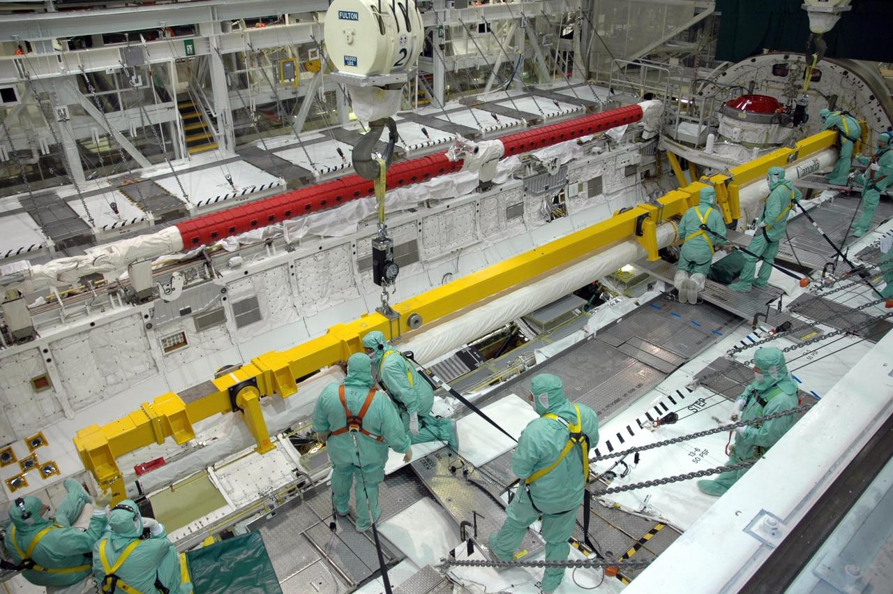
KENNEDY SPACE CENTER, FLA. - In the Orbiter Processing Facility’s bay 1, workers are ready to secure the orbiter boom sensor system on the starboard side of Atlantis’s payload bay for mission STS-117. The 50-foot-long boom attaches to the shuttle arm and provides equipment to inspect the shuttle's heat shield while in space. It contains an intensified television camera (ITVC) and a laser dynamic range imager, which are mounted on a pan and tilt unit, and a laser camera system (LCS) mounted on a stationary bracket. Mission STS-117 will carry the S3/S4 arrays for installation on the International Space Station. Launch of Space Shuttle Atlantis is scheduled for March. Photo credit: NASA/Jack Pfaller
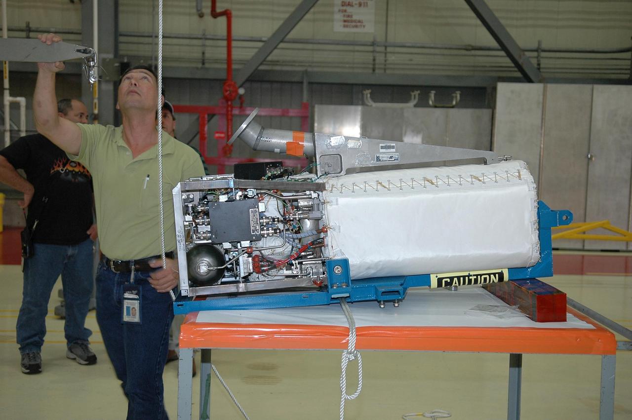
KENNEDY SPACE CENTER, FLA. - In NASA Kennedy Space Center’s Orbiter Processing Facility bay 3, the fuel cell removed from the orbiter Discovery is lowered onto a bracket on the work stand. Fuel cells are located under the forward portion of the payload bay. They make power for the orbiter by mixing hydrogen and oxygen to produce electricity. Fuel cells also create potable water that is pumped into storage tanks for the crew to use in orbit. Discovery is the designated orbiter for the second return-to-flight mission, STS-121, scheduled for launch in May. Photo credit: NASA/Kim Shiflett

KENNEDY SPACE CENTER, FLA. -- A close-up view of the LO2 feed line bracket with the BX265foam insulation and super lightweight ablator, or SLA, cork insulation removed. The BX265 foam insulation will later be reapplied without the SLA. The tank is scheduled to fly on Space Shuttle Discovery in October 2007 on mission STS-120. Discovery's crew will add the module Harmony that will serve as a port for installing additional international laboratories. Harmony will be the first expansion of the living and working space on the complex since the Russian Pirs airlock was installed in 2001. The mission also will move the first set of solar arrays installed on the station to a permanent location on the complex and redeploy them. Photo credit: NASA/Jim Grossmann
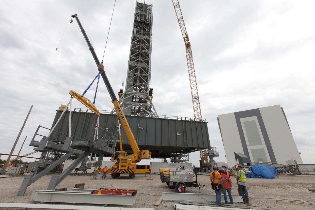
Preparations are underway to lift the bracket for the Orion Service Module Umbilical (OSMU) up for installation on the mobile launcher tower at NASA's Kennedy Space Center in Florida. The mobile launcher tower will be equipped with a number of lines, called umbilicals, that will connect to the Space Launch System rocket and Orion spacecraft for Exploration Mission-1 (EM-1). The OSMU will be located high on the mobile launcher tower and, prior to launch, will transfer liquid coolant for the electronics and air for the Environmental Control System to the Orion service module that houses these critical systems to support the spacecraft. EM-1 is scheduled to launch in 2018. The Ground Systems Development and Operations Program is overseeing installation of the umbilicals.
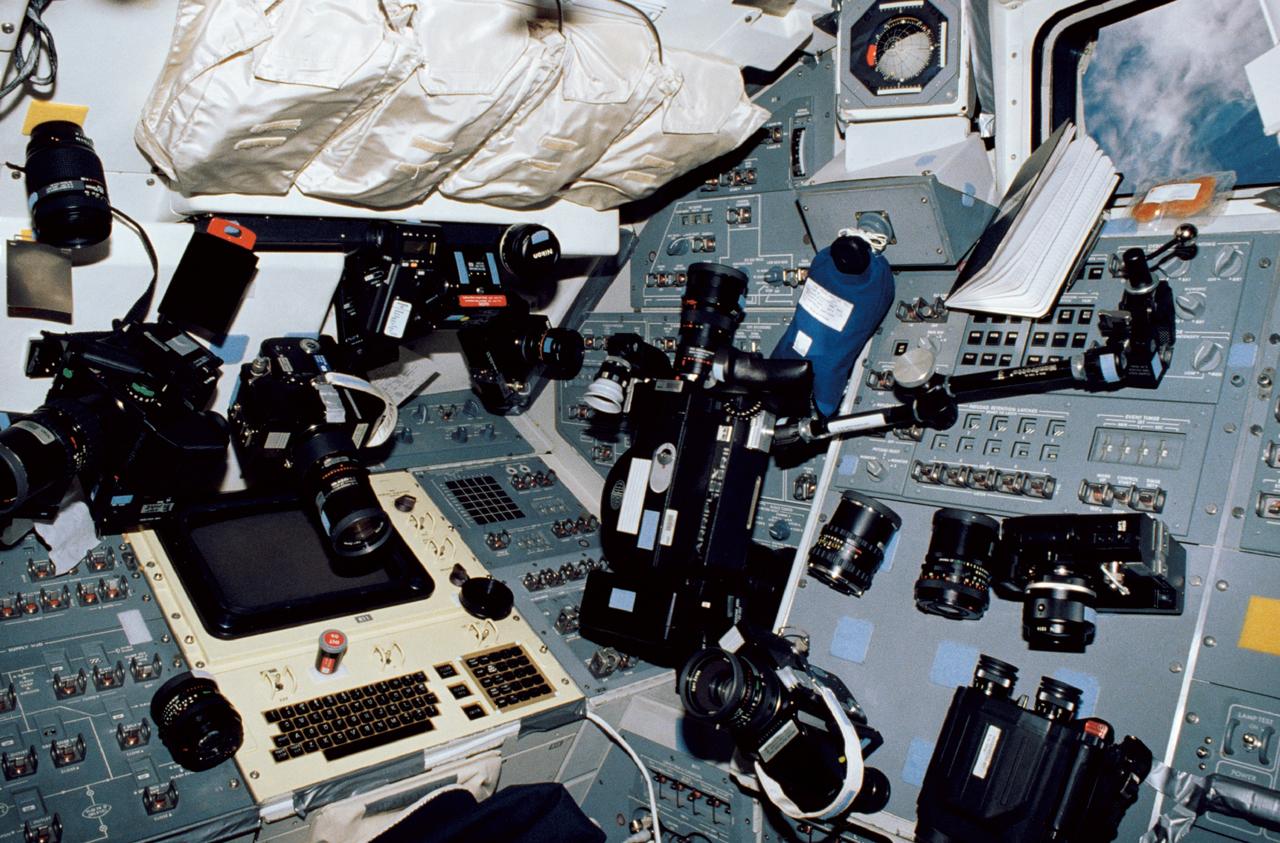
STS035-10-015 (2-10 Dec 1990) --- This busy scene shows cameras and supportive photographic gear temporarily stowed on Space Shuttle Columbia's aft flight deck. It was photographed with a 35mm camera by astronaut Jeffrey A. Hoffman, mission specialist, who called the cluster a "camera forest." The seven STS-35 crewmembers trained to record a wide variety of imagery with an equally broad range of equipment. In addition to cameras, a spot meter, film, a pair of binoculars, a bracket, lenses, lens cleaner and other photographic equipment are in the scene. Clouds over ocean waters are framed by an aft flight deck window at upper right.
A view from below the mobile launcher shows a crane positioning the bracket for the Orion Service Module Umbilical (OSMU) high up for installation on the mobile launcher tower at NASA's Kennedy Space Center in Florida. The mobile launcher tower will be equipped with a number of lines, called umbilicals, that will connect to the Space Launch System rocket and Orion spacecraft for Exploration Mission-1 (EM-1). The OSMU will be located high on the mobile launcher tower and, prior to launch, will transfer liquid coolant for the electronics and air for the Environmental Control System to the Orion service module that houses these critical systems to support the spacecraft. EM-1 is scheduled to launch in 2018. The Ground Systems Development and Operations Program is overseeing installation of the umbilicals.
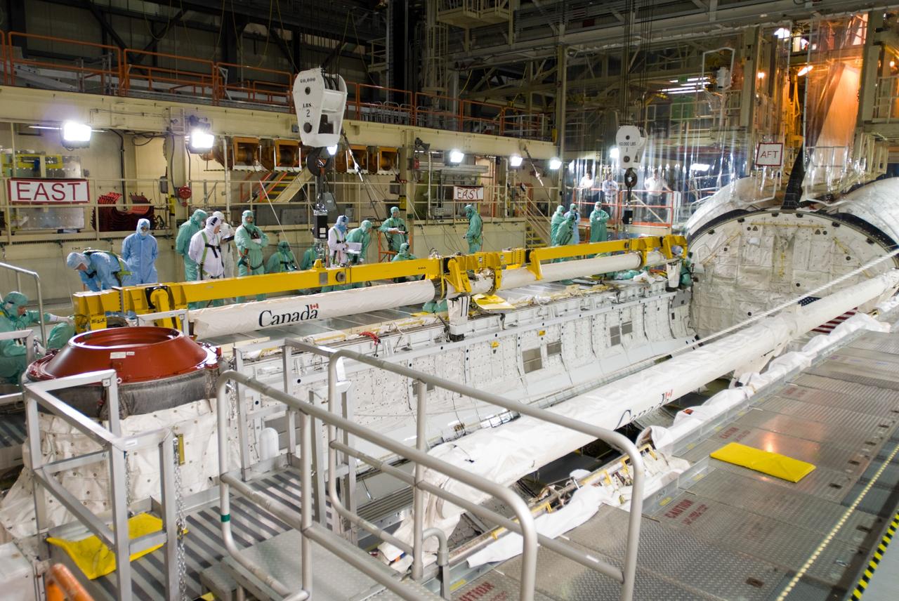
CAPE CANAVERAL, Fla. – In the Orbiter Processing Facility’s bay 3, the orbiter boom sensor system is installed in the payload bay of space shuttle Discovery to support mission STS-128. The 50-foot-long boom attaches to the shuttle arm and provides equipment to inspect the shuttle's heat shield while in space. It contains an intensified television camera (ITVC) and a laser dynamic range imager, which are mounted on a pan and tilt unit, and a laser camera system (LCS) mounted on a stationary bracket. The STS-128 flight will carry science and storage racks to the International Space Station on space shuttle Discovery. Launch of Discovery is targeted for Aug. 6. Photo credit: NASA/Jim Grossmann
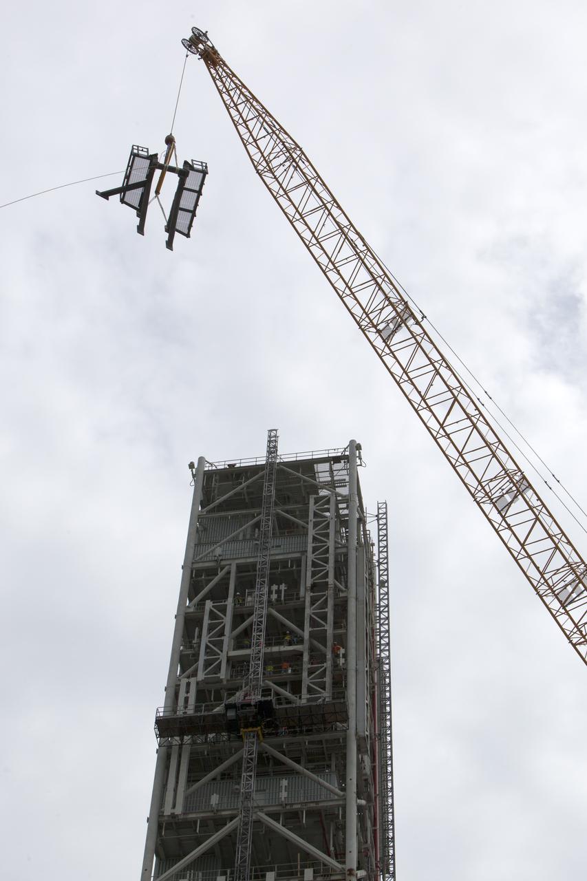
A crane lifts the bracket for the Orion Service Module Umbilical (OSMU) high up for installation on the mobile launcher tower at NASA's Kennedy Space Center in Florida. The mobile launcher tower will be equipped with a number of lines, called umbilicals, that will connect to the Space Launch System rocket and Orion spacecraft for Exploration Mission-1 (EM-1). The OSMU will be located high on the mobile launcher tower and, prior to launch, will transfer liquid coolant for the electronics and air for the Environmental Control System to the Orion service module that houses these critical systems to support the spacecraft. EM-1 is scheduled to launch in 2018. The Ground Systems Development and Operations Program is overseeing installation of the umbilicals.
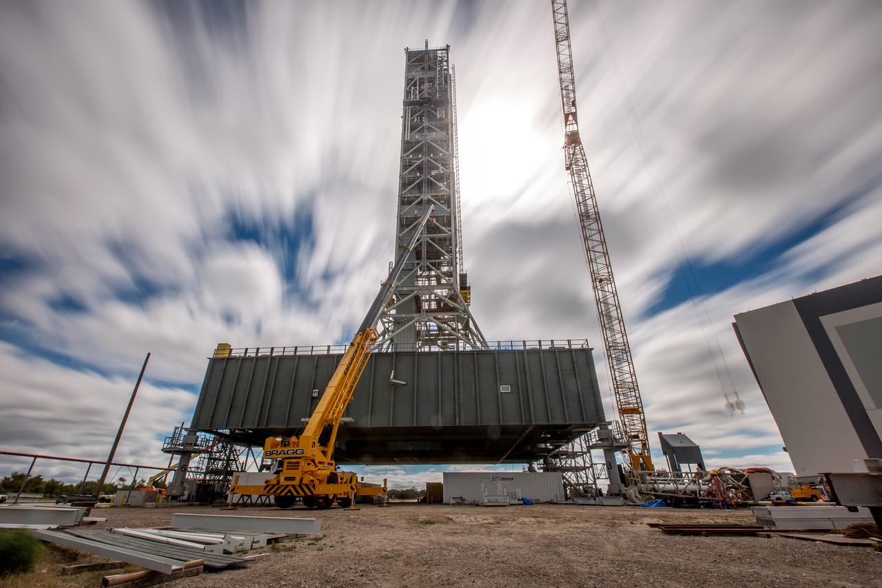
A long-exposure view of the mobile launcher at NASA's Kennedy Space Center in Florida. Cranes and rigging are being used to lift the bracket for the Orion Service Module Umbilical (OSMU) up for installation on the mobile launcher tower. The tower will be equipped with a number of lines, called umbilicals, that will connect to the Space Launch System rocket and Orion spacecraft for Exploration Mission-1 (EM-1). The OSMU will be located high on the mobile launcher tower and, prior to launch, will transfer liquid coolant for the electronics and air for the Environmental Control System to the Orion service module that houses these critical systems to support the spacecraft. EM-1 is scheduled to launch in 2018. The Ground Systems Development and Operations Program is overseeing installation of the umbilicals.
Construction workers and crane specialists high up on the mobile launcher tower monitor the progress as a crane positions the bracket for the Orion Service Module Umbilical (OSMU) for installation on the mobile launcher tower at NASA's Kennedy Space Center in Florida. The tower will be equipped with a number of lines, called umbilicals, that will connect to the Space Launch System rocket and Orion spacecraft for Exploration Mission-1 (EM-1). The OSMU will be located high on the mobile launcher tower and, prior to launch, will transfer liquid coolant for the electronics and air for the Environmental Control System to the Orion service module that houses these critical systems to support the spacecraft. EM-1 is scheduled to launch in 2018. The Ground Systems Development and Operations Program is overseeing installation of the umbilicals.
CAPE CANAVERAL, Fla. – In the Orbiter Processing Facility’s bay 3, workers prepare to install the orbiter boom sensor system in the payload bay of space shuttle Discovery to support mission STS-128. The 50-foot-long boom attaches to the shuttle arm and provides equipment to inspect the shuttle's heat shield while in space. It contains an intensified television camera (ITVC) and a laser dynamic range imager, which are mounted on a pan and tilt unit, and a laser camera system (LCS) mounted on a stationary bracket. The STS-128 flight will carry science and storage racks to the International Space Station on space shuttle Discovery. Launch of Discovery is targeted for Aug. 6. Photo credit: NASA/Jim Grossmann
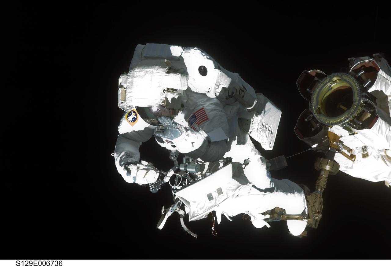
S129-E-006736 (19 Nov. 2009) --- Astronaut Robert L. Satcher Jr., STS-129 mission specialist, participates in the mission's first session of extravehicular activity (EVA) as construction and maintenance continue on the International Space Station. During the six-hour, 37-minute spacewalk, Satcher and astronaut Mike Foreman (out of frame), mission specialist, installed a spare S-band antenna structural assembly to the Z1 segment of the station?s truss, or backbone. Foreman and Satcher also installed a set of cables for a future space-to-ground antenna on the Destiny laboratory and replaced a handrail on the Unity node with a new bracket used to route an ammonia cable that will be needed for the Tranquility node when it is delivered next year. The two spacewalkers also repositioned a cable connector on Unity, checked S0 truss cable connections, and lubricated latching snares on the Kibo robotic arm and the station?s mobile base system.
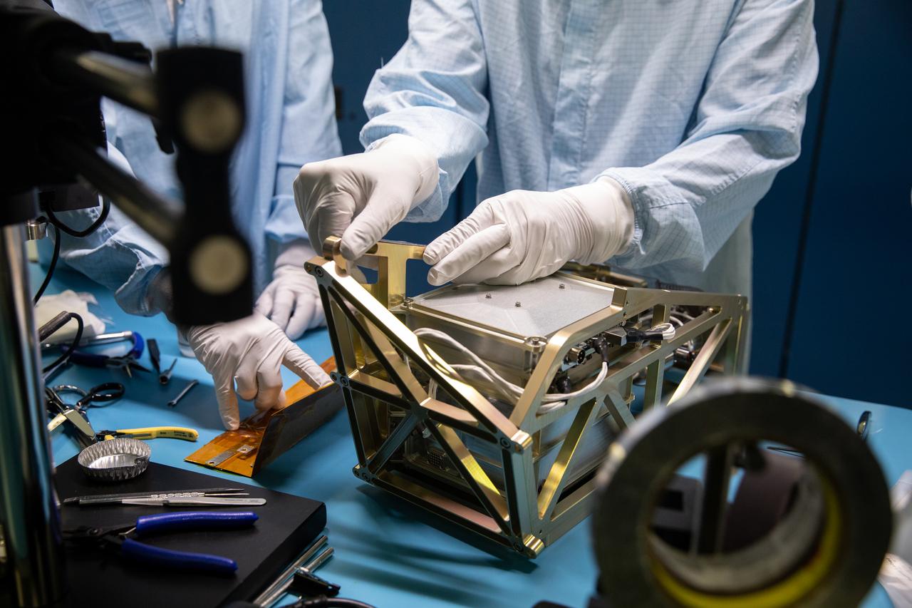
Inside the Space Station Processing Facility at NASA’s Kennedy Space Center in Florida, an engineer installs the Mass Spectrometer observing lunar operations (MSolo) onto its radiator bracket on June 14, 2022. Having successfully completed its thermal vacuum testing, the unit will undergo vibration testing later this month. This spectrometer is part of the PRIME-1 (Polar Resources Ice Mining Experiment-1) payload suite, slated to launch to the Moon in 2023 with Intuitive Machines. MSolo is a commercial off-the-shelf mass spectrometer modified to work in space and it will help analyze the chemical makeup of landing sites on the Moon, as well as study water on the lunar surface. MSolo is manifested to fly on four of the agency’s Commercial Lunar Payload Delivery Service missions where under Artemis, commercial deliveries beginning in 2023 will perform science experiments, test technologies, and demonstrate capabilities to help NASA explore the Moon and prepare for human missions.
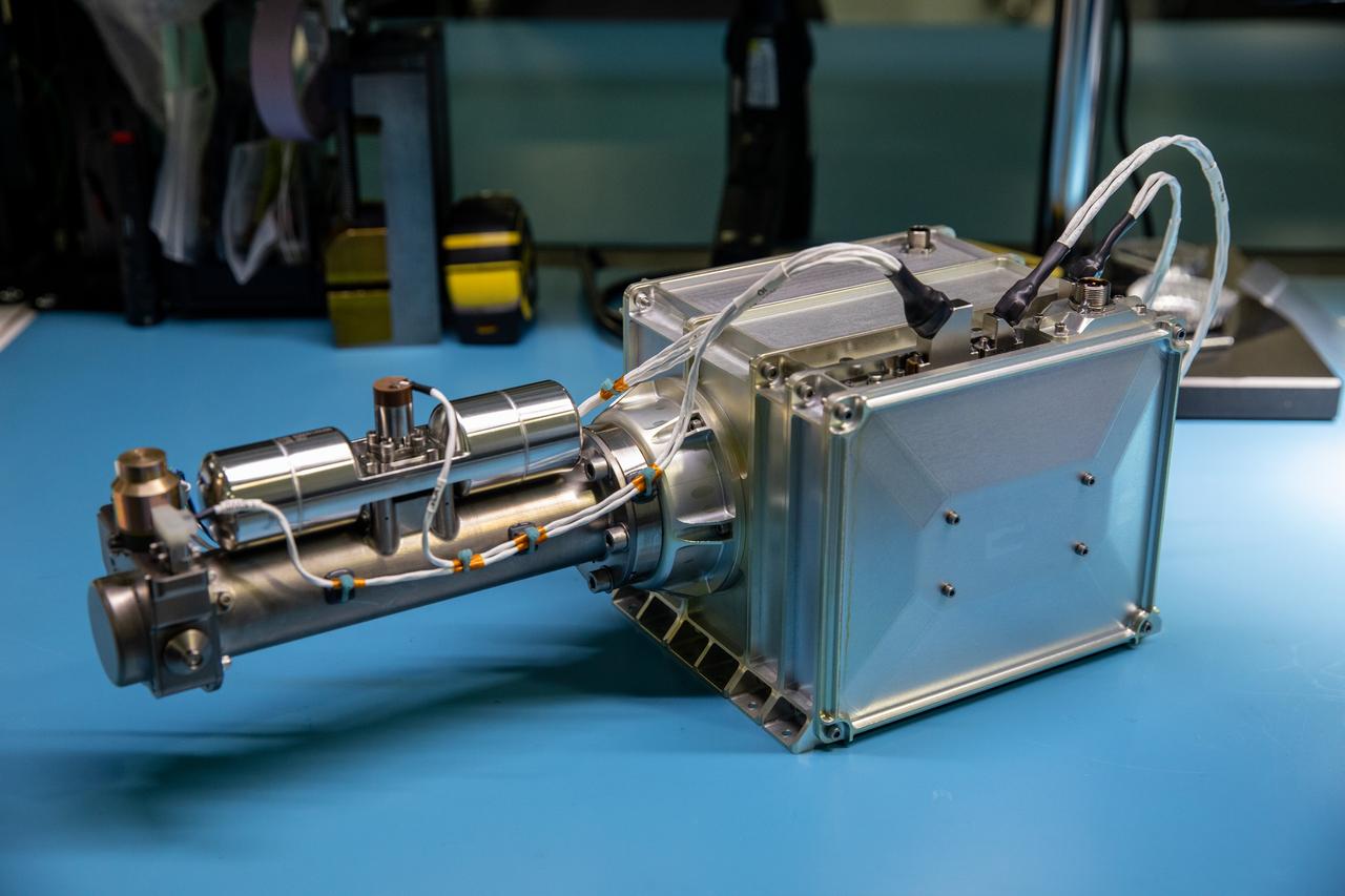
Inside the Space Station Processing Facility at NASA’s Kennedy Space Center in Florida, the Mass Spectrometer observing lunar operations (MSolo) is being installed on a radiator bracket on June 14, 2022. Having successfully completed its thermal vacuum testing, the unit will undergo vibration testing later this month. This spectrometer is part of the PRIME-1 (Polar Resources Ice Mining Experiment-1) payload suite, slated to launch to the Moon in 2023 with Intuitive Machines. MSolo is a commercial off-the-shelf mass spectrometer modified to work in space and it will help analyze the chemical makeup of landing sites on the Moon, as well as study water on the lunar surface. MSolo is manifested to fly on four of the agency’s Commercial Lunar Payload Delivery Service missions where under Artemis, commercial deliveries beginning in 2023 will perform science experiments, test technologies, and demonstrate capabilities to help NASA explore the Moon and prepare for human missions.
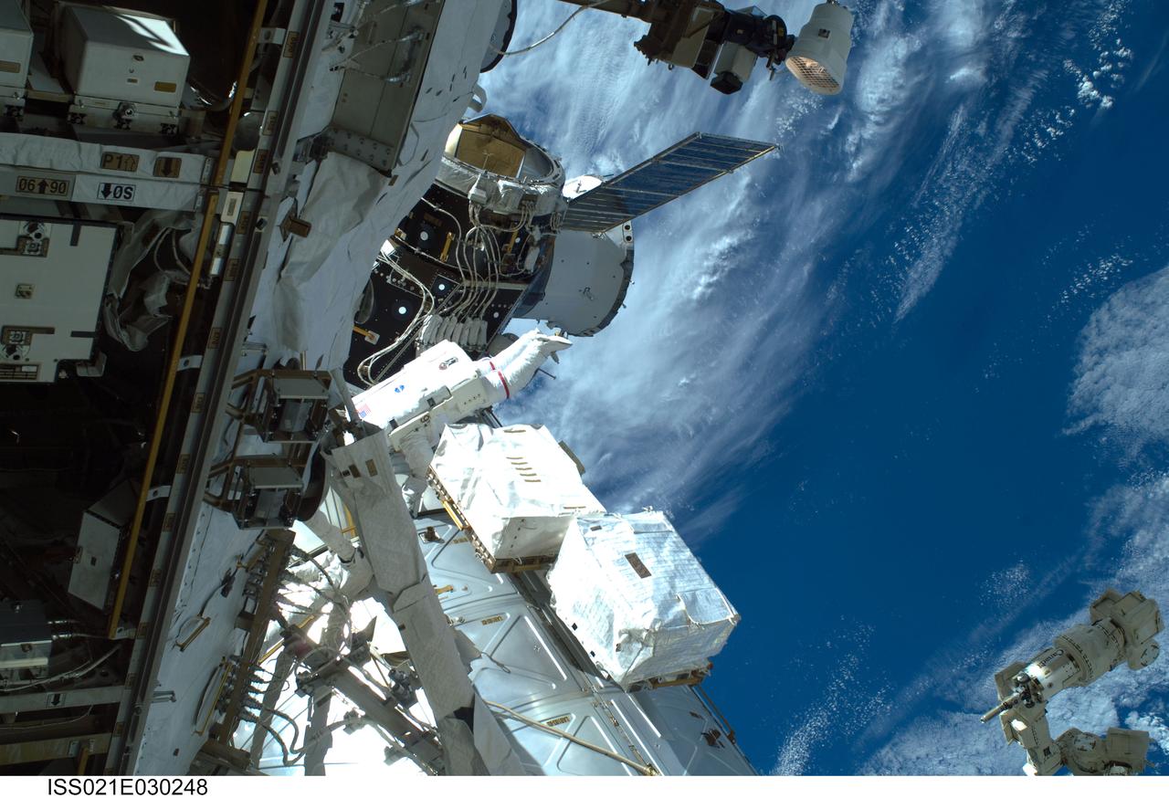
ISS021-E-030248 (19 Nov. 2009) --- Astronaut Mike Foreman, STS-129 mission specialist, participates in the mission's first session of extravehicular activity (EVA) as construction and maintenance continue on the International Space Station. During the six-hour, 37-minute spacewalk, Foreman and astronaut Robert L. Satcher Jr. (out of frame), mission specialist, installed a spare S-band antenna structural assembly to the Z1 segment of the station?s truss, or backbone. Foreman and Satcher also installed a set of cables for a future space-to-ground antenna on the Destiny laboratory and replaced a handrail on the Unity node with a new bracket used to route an ammonia cable that will be needed for the Tranquility node when it is delivered next year. The two spacewalkers also repositioned a cable connector on Unity, checked S0 truss cable connections, and lubricated latching snares on the Kibo robotic arm and the station?s mobile base system.
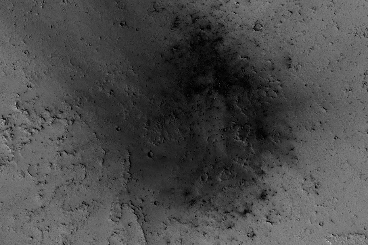
NASA's Mars Reconnaissance Orbiter has been observing Mars in sharp detail for more than a decade, enabling it to document many types of changes, such as the way winds alter the appearance of this recent impact site. The space-rock impact that created this blast zone occurred sometime between September 2005 and February 2006, as bracketed by observations made with the Mars Orbiter Camera on NASA's Mars Global Surveyor spacecraft. The location is between two large volcanos, named Ascraeus Mons and Pavonis Mons, in a dusty area of the Tharsis region of Mars. During the period from 2007 to 2012, winds blowing through the pass between the volcanoes darkened some regions and brightened others, probably by removing and depositing dust. The view covers an area about 1.0 mile (1.6 kilometers) across, at 7 degrees north latitude, 248 degrees east longitude. North is toward the top. An animation is availalble at http://photojournal.jpl.nasa.gov/catalog/PIA21267
KENNEDY SPACE CENTER, FLA. -- At Launch Pad 39A, a team of external tank specialists from Lockheed Martin and the United Space Alliance undertakes the task of removing the hydrogen feed-through connector in support of space shuttle Atlantis' STS-122 mission. Here, a technician removes a pair of support brackets. Some of the tank's engine cutoff sensors, or ECO sensors, failed during propellant tanking for launch attempts on Dec. 6 and Dec. 9. Results of a tanking test on Dec. 18 pointed to an open circuit in the feed-through connector wiring, which is located at the base of the tank. The feed-through connector passes the wires from the inside of the tank to the outside. After the data from additional testing on the connector is analyzed, shuttle program managers will decide on a forward plan. Launch of STS-122 is targeted for January 2008. Photo credit: NASA/George Shelton

CAPE CANAVERAL, Fla. -- Space shuttle Discovery's external fuel tank is outfitted with approximately 89 strain gauges, thermocouples and wiring in preparation for a tanking test no earlier than Dec. 17 on Launch Pad 39A at NASA's Kennedy Space Center in Florida. During the test, engineers will monitor what happens to 21-foot long, U-shaped aluminum brackets, called stringers, located at the external tank's intertank area, as well as the newly replaced ground umbilical carrier plate (GUCP), during the loading of cryogenic propellants. Discovery's first launch attempt for STS-133 was scrubbed in early November due to a hydrogen gas leak at GUCP. The next launch opportunity is no earlier than Feb. 3, 2011. For more information on STS-133, visit www.nasa.gov/mission_pages/shuttle/shuttlemissions/sts133/. Photo credit: NASA/Jim Grossmann
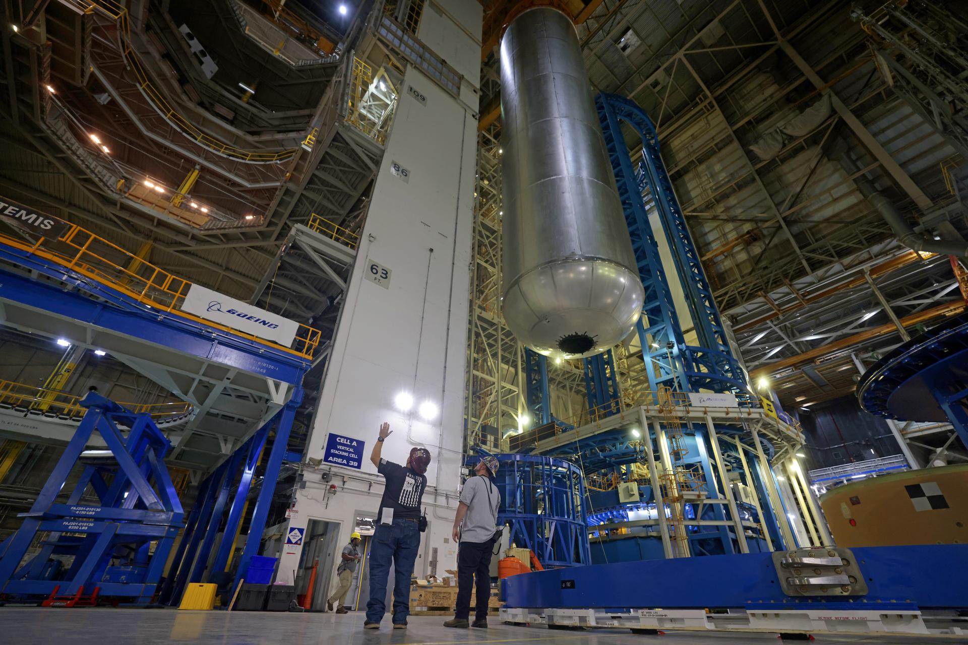
Teams at NASA’s Michoud Assembly Facility in New Orleans lift the 130-foot-tall liquid hydrogen tank off the vertical assembly center on Nov. 14. This is the fourth liquid hydrogen tank manufactured at the facility for the agency’s SLS (Space Launch System) rocket. The completed tank will be loaded into a production cell for technicians to remove the lift tool, perform dimensional scans, and then install brackets, which will allow the move crew to break the tank over from a vertical to a horizontal configuration. The propellant tank is one of five major elements that make up the 212-foot-tall rocket stage. The core stage, along with its four RS-25 engines, produce more than two million pounds of thrust to help launch NASA’s Orion spacecraft, astronauts, and supplies beyond Earth’s orbit and to the lunar surface for Artemis. Image credit: NASA/Michael DeMocker
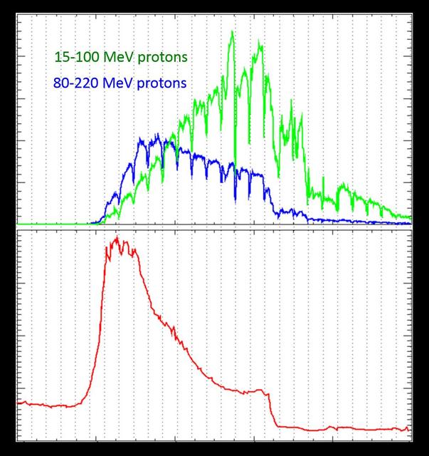
Energetic particles from a large solar storm in September 2017 were seen both in Mars orbit and on the surface of Mars by NASA missions to the Red Planet. The horizontal axis for both parts of this graphic is the time from Sept. 10 to Sept. 15, 2017. The upper portion of this graphic shows the increase in protons in two ranges of energy levels (15- to-100 million electron volts and 80-to-220 million electron volts), as recorded by the Solar Energetic Particle instrument on NASA's on NASA's Mars Atmosphere and Volatile Evolution orbiter, or MAVEN. The lower portion shows the radiation dose on the Martian surface, in micrograys per day, as measured by the Radiation Assessment Monitor instrument on NASA' Curiosity Mars rover. Micrograys are unit of measurement for absorbed radiation dose. Note that only protons in the higher bracket of energy levels penetrate the atmosphere enough to be detected on the surface. https://photojournal.jpl.nasa.gov/catalog/PIA21856
KENNEDY SPACE CENTER, FLA. -- The BX265 foam insulation and super lightweight ablator, or SLA, cork insulation has been removed from the L02 feed line bracket that is attached to the external tank. Also visible is the adjacent LO2 feed line. The BX265 foam insulation will later be reapplied without the SLA. The tank is scheduled to fly on Space Shuttle Discovery in October 2007 on mission STS-120. Discovery's crew will add the module Harmony that will serve as a port for installing additional international laboratories. Harmony will be the first expansion of the living and working space on the complex since the Russian Pirs airlock was installed in 2001. The mission also will move the first set of solar arrays installed on the station to a permanent location on the complex and redeploy them. Photo credit: NASA/Jim Grossmann
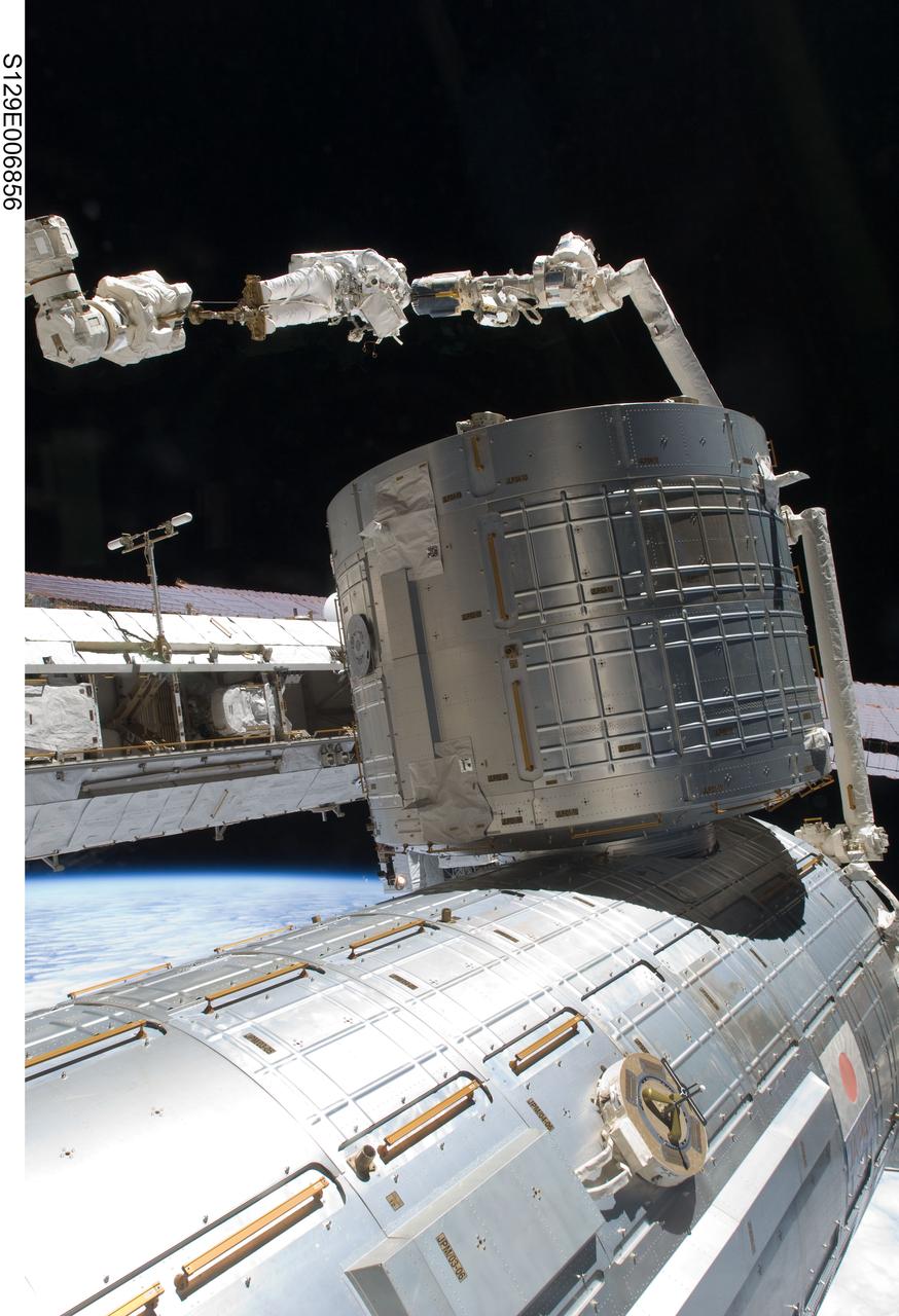
S129-E-006856 (19 Nov. 2009) --- Anchored to a Canadarm2 mobile foot restraint, astronaut Robert L. Satcher Jr., STS-129 mission specialist, participates in the mission's first session of extravehicular activity (EVA) as construction and maintenance continue on the International Space Station. During the six-hour, 37-minute spacewalk, Satcher and astronaut Mike Foreman (out of frame), mission specialist, installed a spare S-band antenna structural assembly to the Z1 segment of the station?s truss, or backbone. Foreman and Satcher also installed a set of cables for a future space-to-ground antenna on the Destiny laboratory and replaced a handrail on the Unity node with a new bracket used to route an ammonia cable that will be needed for the Tranquility node when it is delivered next year. The two spacewalkers also repositioned a cable connector on Unity, checked S0 truss cable connections, and lubricated latching snares on the Kibo robotic arm and the station?s mobile base system.
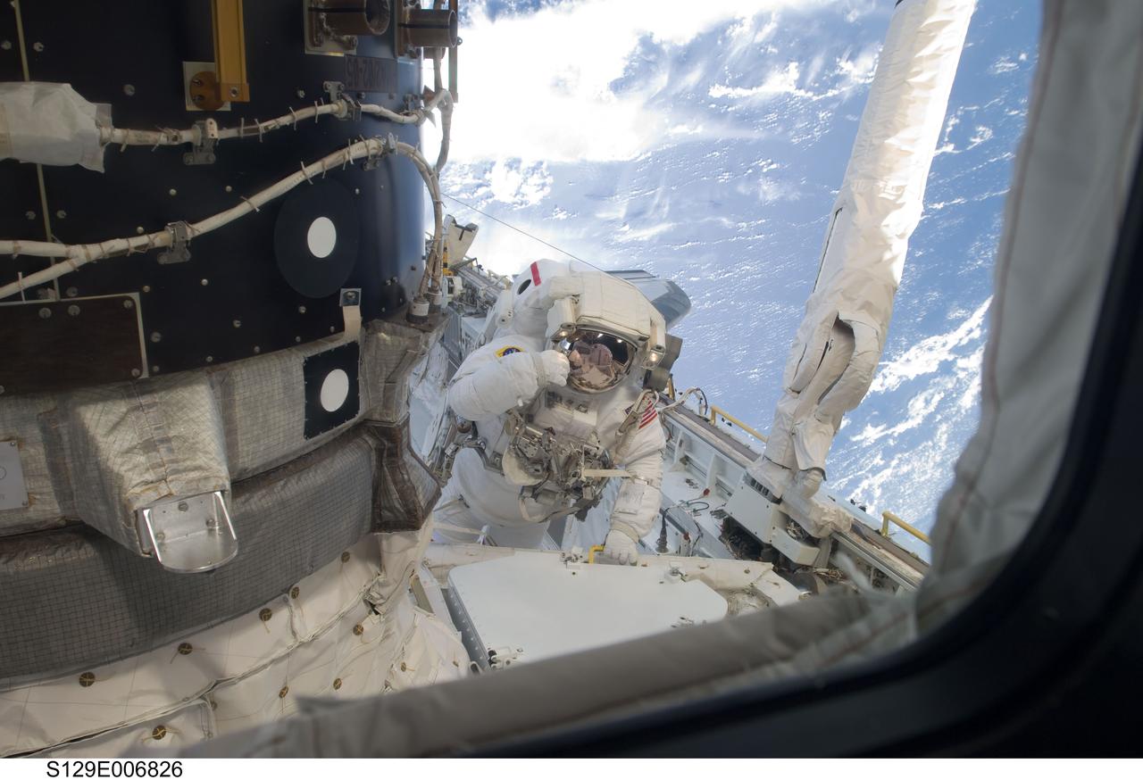
S129-E-006826 (19 Nov. 2009) --- Astronaut Mike Foreman, STS-129 mission specialist, participates in the mission's first session of extravehicular activity (EVA) as construction and maintenance continue on the International Space Station. During the six-hour, 37-minute spacewalk, Foreman and astronaut Robert L. Satcher Jr. (out of frame), mission specialist, installed a spare S-band antenna structural assembly to the Z1 segment of the station?s truss, or backbone. Foreman and Satcher also installed a set of cables for a future space-to-ground antenna on the Destiny laboratory and replaced a handrail on the Unity node with a new bracket used to route an ammonia cable that will be needed for the Tranquility node when it is delivered next year. The two spacewalkers also repositioned a cable connector on Unity, checked S0 truss cable connections, and lubricated latching snares on the Kibo robotic arm and the station?s mobile base system.
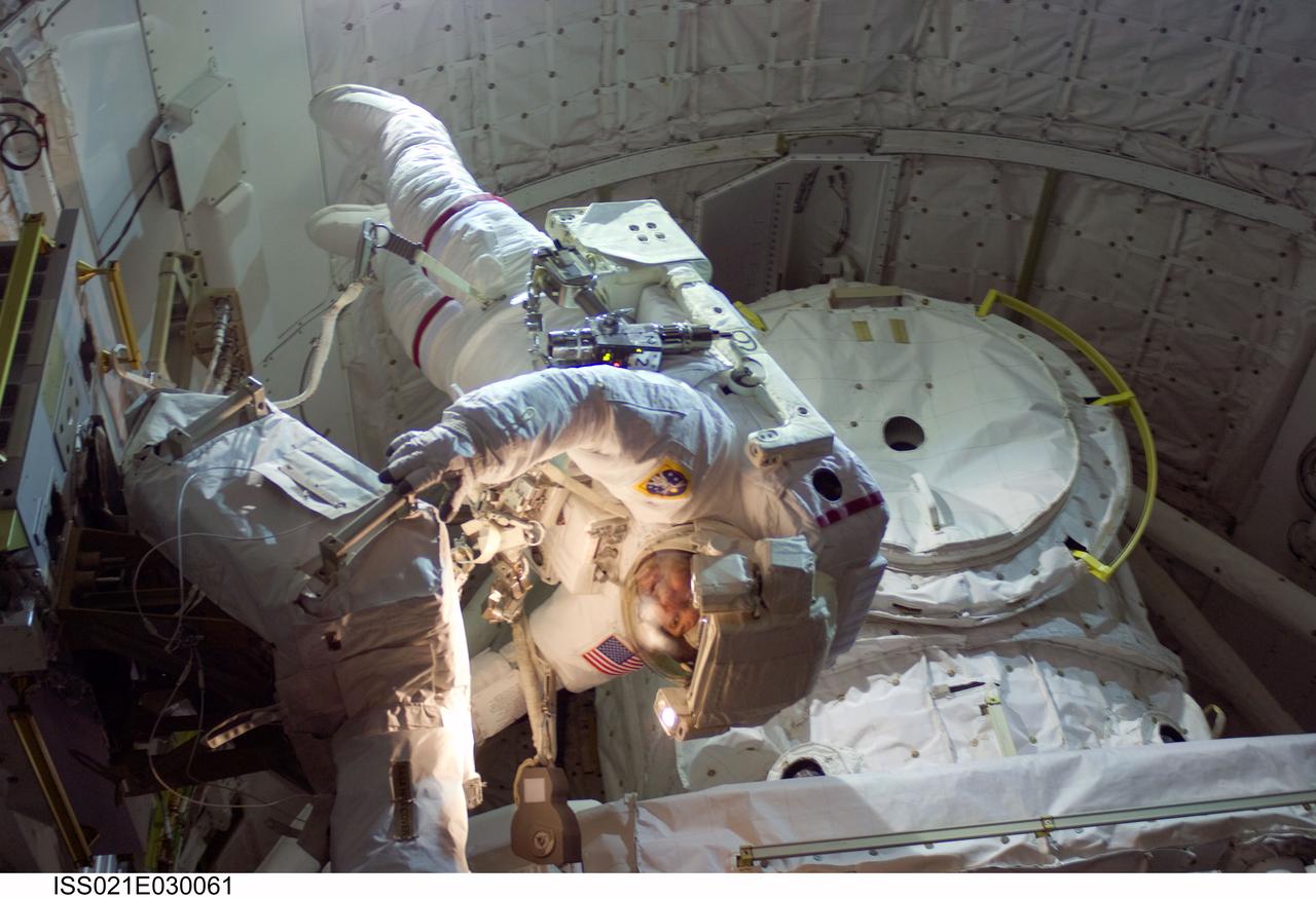
ISS021-E-030061 (19 Nov. 2009) --- Astronaut Mike Foreman, STS-129 mission specialist, participates in the mission's first session of extravehicular activity (EVA) as construction and maintenance continue on the International Space Station. During the six-hour, 37-minute spacewalk, Foreman and astronaut Robert L. Satcher Jr. (out of frame), mission specialist, installed a spare S-band antenna structural assembly to the Z1 segment of the station?s truss, or backbone. Foreman and Satcher also installed a set of cables for a future space-to-ground antenna on the Destiny laboratory and replaced a handrail on the Unity node with a new bracket used to route an ammonia cable that will be needed for the Tranquility node when it is delivered next year. The two spacewalkers also repositioned a cable connector on Unity, checked S0 truss cable connections, and lubricated latching snares on the Kibo robotic arm and the station?s mobile base system.
KENNEDY SPACE CENTER, FLA. - A crack formed on a piece of insulation on a strut that attaches the liquid oxygen feedline to External Tank-119, being used to launch space shuttle mission STS-121. This piece of foam, weighing approximately 0.0057 pounds, is three inches long and one-eighth to one-quarter inch wide. It fell from the tank and was recovered by the Ice Team from the mobile launch platform at Pad 39B. It is believed that the rain experienced during yesterday’s launch attempt of Discovery caused water to run down the feedline and form ice near the strut next to the feedline bracket. As the tank warmed and expanded, the ice that formed most likely pinched the foam on the top of the strut, causing a crack and eventual loss of the small piece of foam. Photo credit: NASA
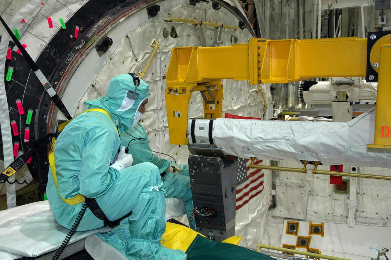
KENNEDY SPACE CENTER, FLA. - In the Orbiter Processing Facility’s bay 1, workers watch closely as the orbiter boom sensor system is lowered into place on the starboard side of Atlantis’s payload bay for mission STS-117. The 50-foot-long boom attaches to the shuttle arm and provides equipment to inspect the shuttle's heat shield while in space. It contains an intensified television camera (ITVC) and a laser dynamic range imager, which are mounted on a pan and tilt unit, and a laser camera system (LCS) mounted on a stationary bracket. Mission STS-117 will carry the S3/S4 arrays for installation on the International Space Station. Launch of Space Shuttle Atlantis is scheduled for March. Photo credit: NASA/Jack Pfaller
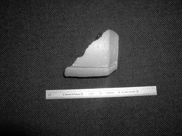
KENNEDY SPACE CENTER, FLA. - A piece of insulation - three inches long, one-eighth to one-quarter inch wide and weighing approximately 0.0057 pounds - was liberated from a strut that attaches the liquid oxygen feedline to External Tank-119. The tank is being used to launch space shuttle mission STS-121. It was recovered by the Ice Team from the mobile launch platform at Pad 39B. It is believed that the rain experienced during yesterday’s launch attempt of Discovery caused water to run down the feedline and form ice near the strut next to the feedline bracket. As the tank warmed and expanded, the ice that formed most likely pinched the foam on the top of the strut, causing a crack and eventual loss of the small piece of foam. Photo credit: NASA
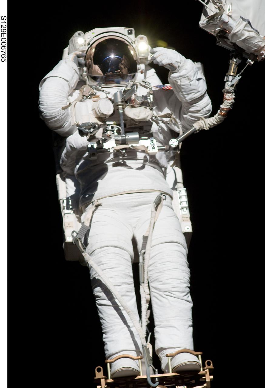
S129-E-006765 (19 Nov. 2009) --- Anchored to a Canadarm2 mobile foot restraint, astronaut Robert L. Satcher Jr., STS-129 mission specialist, participates in the mission's first session of extravehicular activity (EVA) as construction and maintenance continue on the International Space Station. During the six-hour, 37-minute spacewalk, Satcher and astronaut Mike Foreman (out of frame), mission specialist, installed a spare S-band antenna structural assembly to the Z1 segment of the station?s truss, or backbone. Foreman and Satcher also installed a set of cables for a future space-to-ground antenna on the Destiny laboratory and replaced a handrail on the Unity node with a new bracket used to route an ammonia cable that will be needed for the Tranquility node when it is delivered next year. The two spacewalkers also repositioned a cable connector on Unity, checked S0 truss cable connections, and lubricated latching snares on the Kibo robotic arm and the station?s mobile base system.
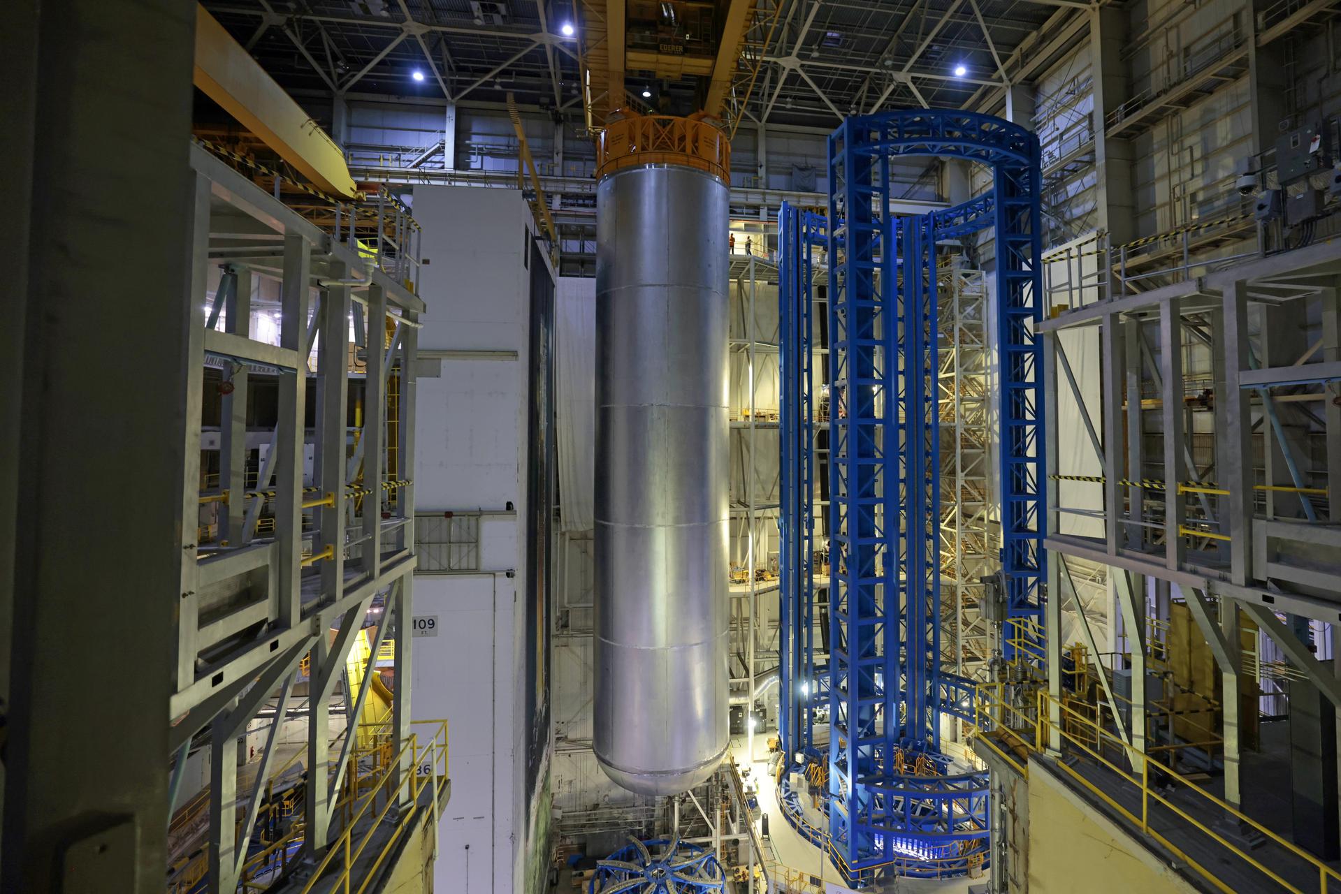
Teams at NASA’s Michoud Assembly Facility in New Orleans lift the 130-foot-tall liquid hydrogen tank off the vertical assembly center on Nov. 14. This is the fourth liquid hydrogen tank manufactured at the facility for the agency’s SLS (Space Launch System) rocket. The completed tank will be loaded into a production cell for technicians to remove the lift tool, perform dimensional scans, and then install brackets, which will allow the move crew to break the tank over from a vertical to a horizontal configuration. The propellant tank is one of five major elements that make up the 212-foot-tall rocket stage. The core stage, along with its four RS-25 engines, produce more than two million pounds of thrust to help launch NASA’s Orion spacecraft, astronauts, and supplies beyond Earth’s orbit and to the lunar surface for Artemis. Image credit: NASA/Michael DeMocker
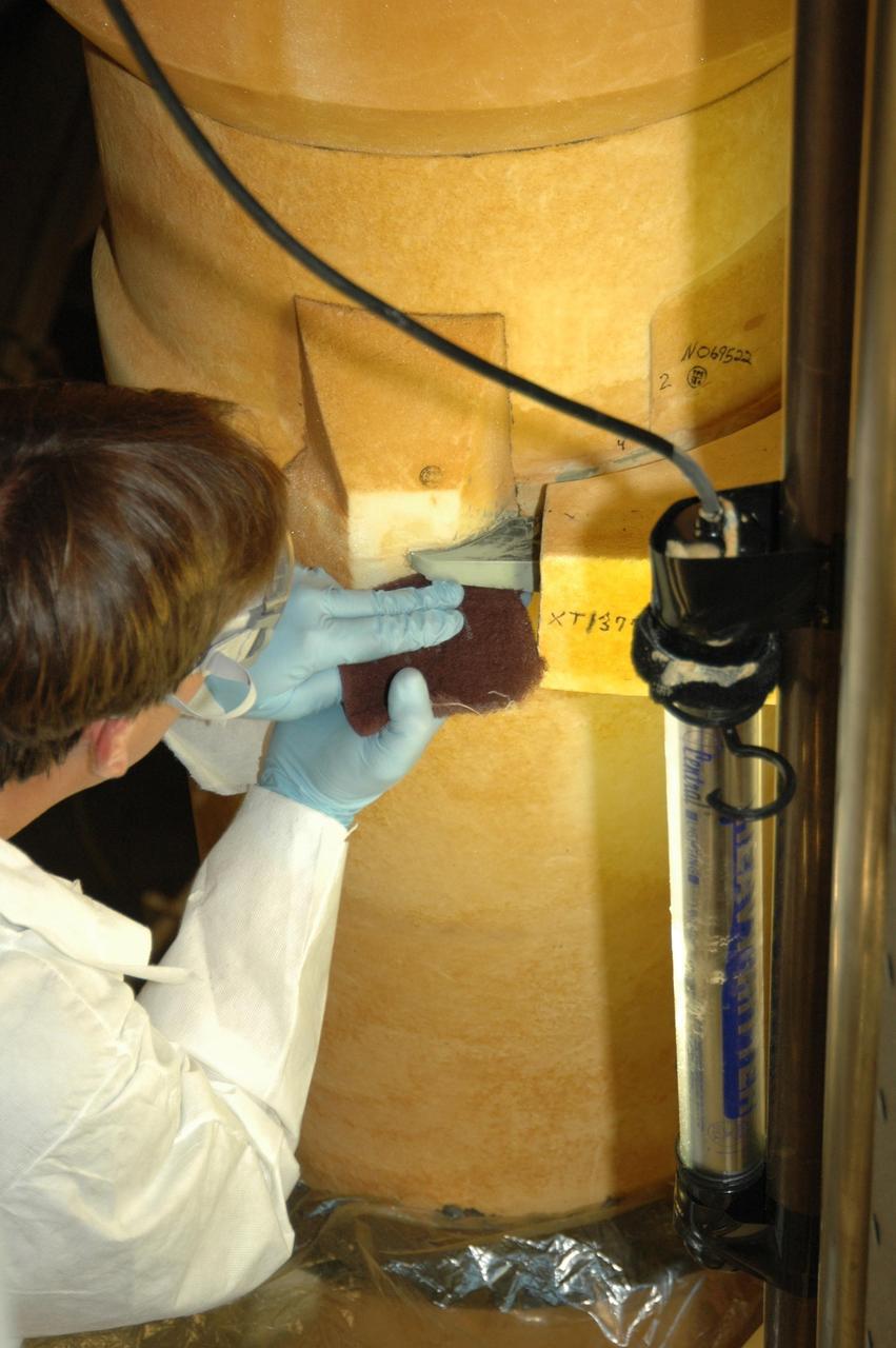
KENNEDY SPACE CENTER, FLA. -- The super lightweight ablator, or SLA, cork insulation has been removed from the external tank and a United Space Alliance external tank technician sands off the residue from the LO2 feed line bracket. The BX265 foam insulation will later be reapplied without the SLA. The tank is scheduled to fly on Space Shuttle Discovery in October 2007 on mission STS-120. Discovery's crew will add the module Harmony that will serve as a port for installing additional international laboratories. Harmony will be the first expansion of the living and working space on the complex since the Russian Pirs airlock was installed in 2001. The mission also will move the first set of solar arrays installed on the station to a permanent location on the complex and redeploy them. Photo credit: NASA/Jim Grossmann
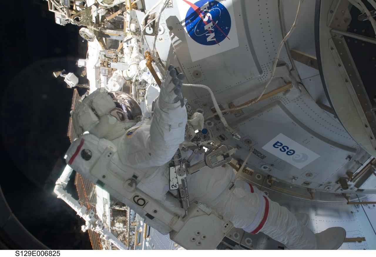
S129-E-006825 (19 Nov. 2009) --- Astronaut Mike Foreman, STS-129 mission specialist, works near the Columbus laboratory during the mission's first session of extravehicular activity (EVA) as construction and maintenance continue on the International Space Station. During the six-hour, 37-minute spacewalk, Foreman and astronaut Robert L. Satcher Jr. (out of frame), mission specialist, installed a spare S-band antenna structural assembly to the Z1 segment of the station?s truss, or backbone. Foreman and Satcher also installed a set of cables for a future space-to-ground antenna on the Destiny laboratory and replaced a handrail on the Unity node with a new bracket used to route an ammonia cable that will be needed for the Tranquility node when it is delivered next year. The two spacewalkers also repositioned a cable connector on Unity, checked S0 truss cable connections, and lubricated latching snares on the Kibo robotic arm and the station?s mobile base system.
Inside the Space Station Processing Facility at NASA’s Kennedy Space Center in Florida, an engineer installs the Mass Spectrometer observing lunar operations (MSolo) onto its radiator bracket on June 14, 2022. Having successfully completed its thermal vacuum testing, the unit will undergo vibration testing later this month. This spectrometer is part of the PRIME-1 (Polar Resources Ice Mining Experiment-1) payload suite, slated to launch to the Moon in 2023 with Intuitive Machines. MSolo is a commercial off-the-shelf mass spectrometer modified to work in space and it will help analyze the chemical makeup of landing sites on the Moon, as well as study water on the lunar surface. MSolo is manifested to fly on four of the agency’s Commercial Lunar Payload Delivery Service missions where under Artemis, commercial deliveries beginning in 2023 will perform science experiments, test technologies, and demonstrate capabilities to help NASA explore the Moon and prepare for human missions.