CAPE CANAVERAL, Fla. - NASA astronaut candidate Andrew Morgan looks over the beach while standing at the Beach House at NASA's Kennedy Space Center. The Beach House is a traditional gathering place for astronauts before they fly into space. The astronaut class of 2013 was selected by NASA after an extensive year-and-a-half search. The new group will help the agency push the boundaries of exploration and travel to new destinations in the solar system. To learn more about the astronaut class of 2013, visit: http://www.nasa.gov/astronauts/2013astroclass.html Photo credit: NASA/Daniel Casper
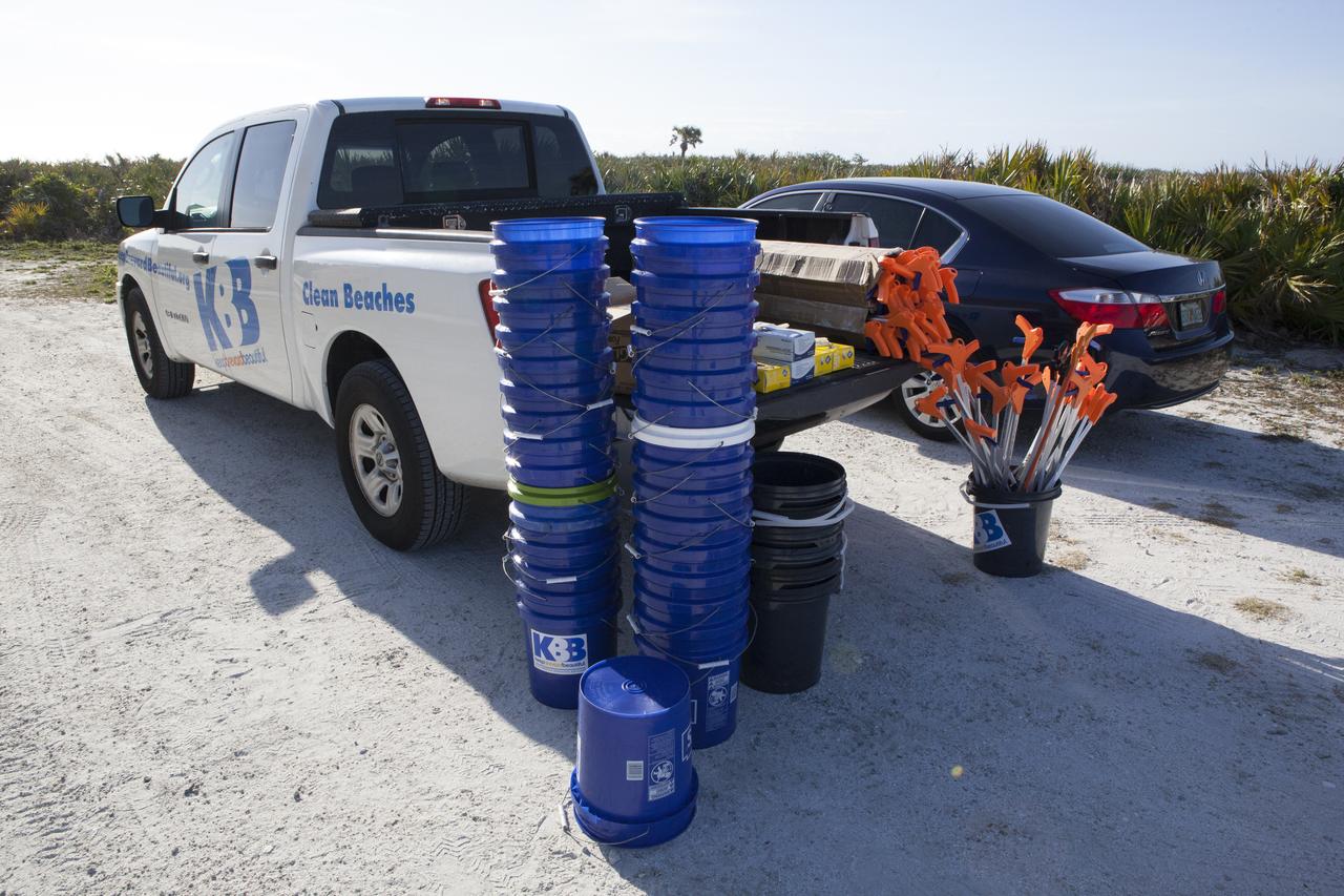
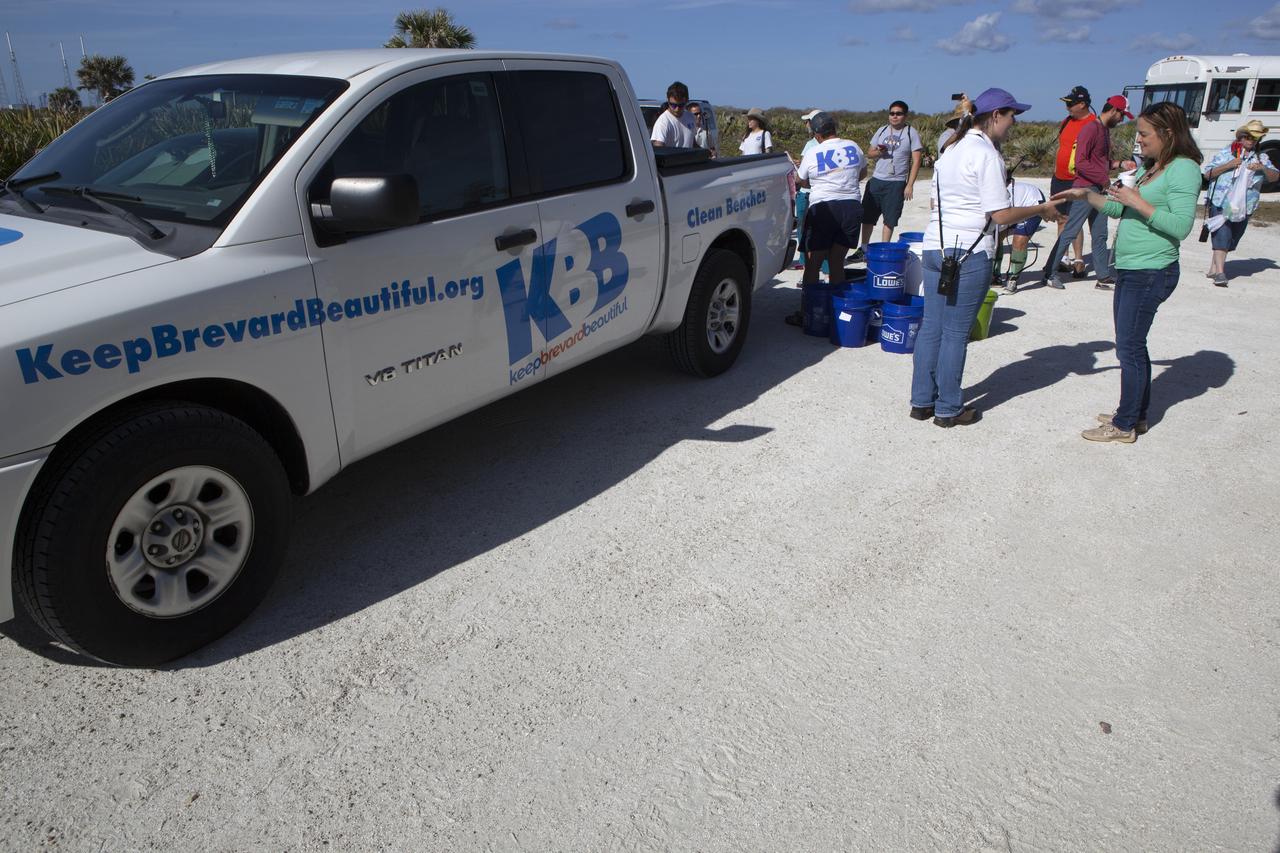
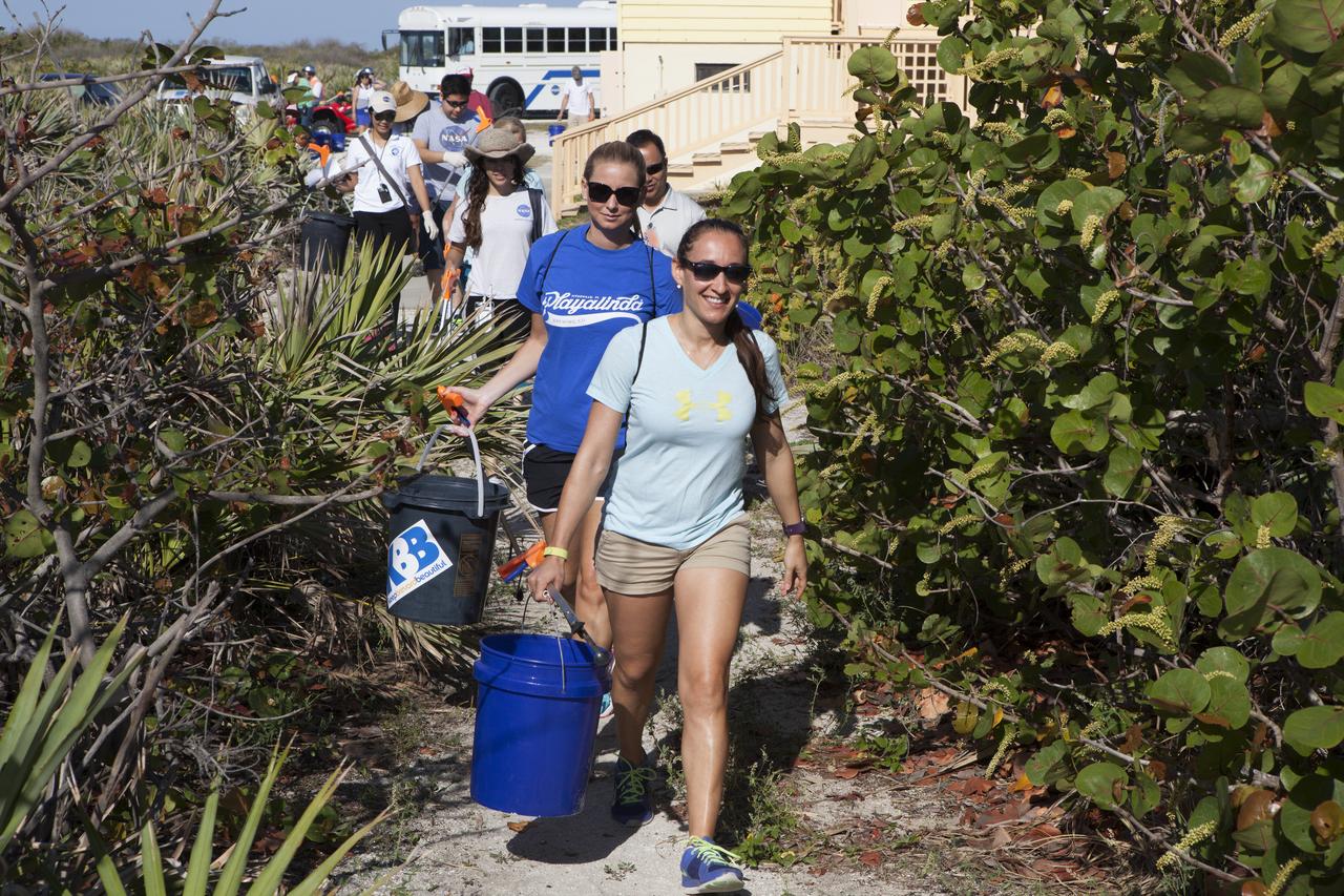
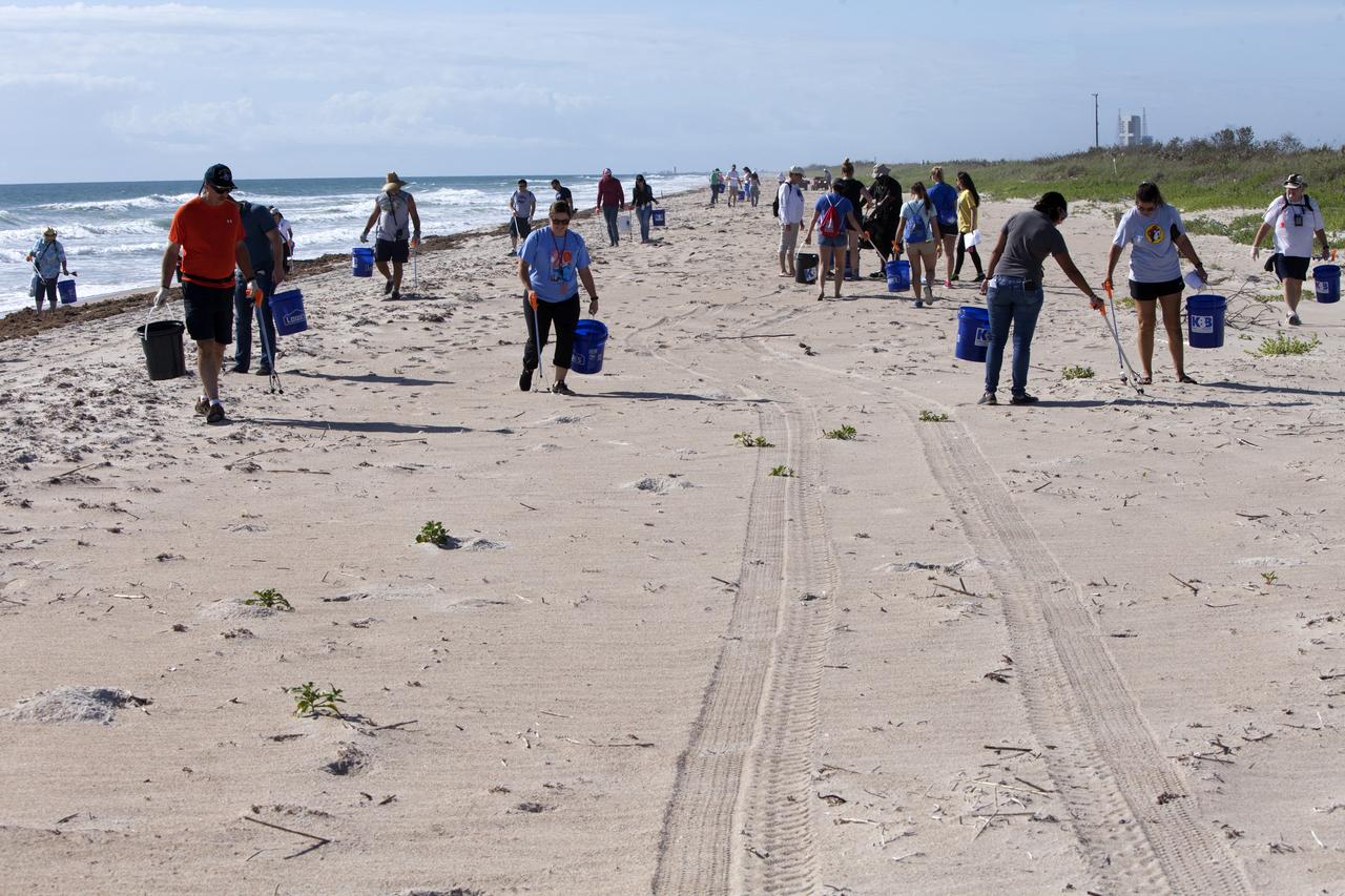
About 50 participants led by NASA Kennedy Space Center's Employee Resource Groups picked up about 20 bags of trash and other large debris along the center's shoreline before turtle-nesting season as a community service. Sea turtle-nesting season begins in about one month. Unlike what might be found along a public beach, all of the debris that litters Kennedy’s restricted beaches washes ashore after being discarded at sea. Of the 72 miles of beach that form the eastern boundary of Brevard County, Florida, about six of those miles line Kennedy.
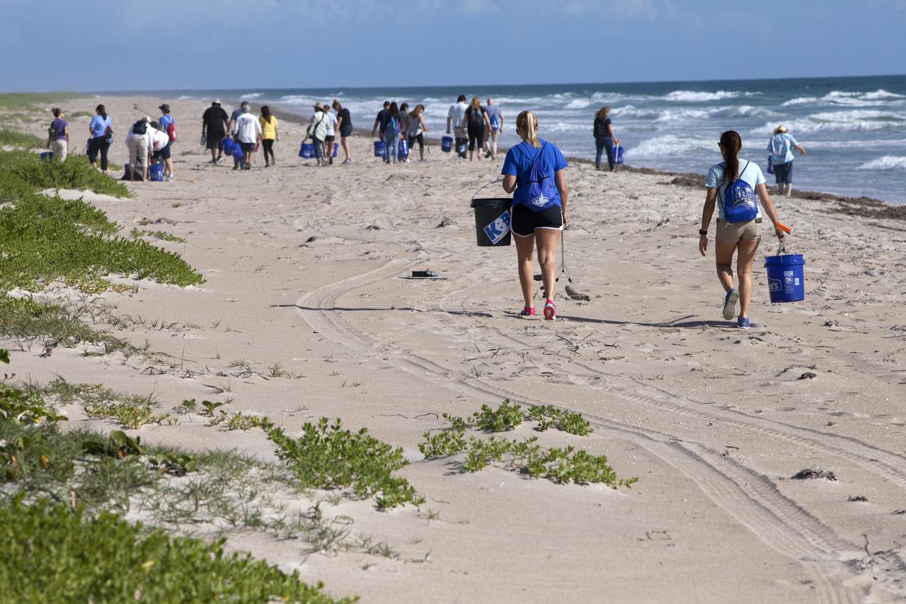
About 50 participants led by NASA Kennedy Space Center's Employee Resource Groups picked up about 20 bags of trash and other large debris along the center's shoreline before turtle-nesting season as a community service. Sea turtle-nesting season begins in about one month. Unlike what might be found along a public beach, all of the debris that litters Kennedy’s restricted beaches washes ashore after being discarded at sea. Of the 72 miles of beach that form the eastern boundary of Brevard County, Florida, about six of those miles line Kennedy.
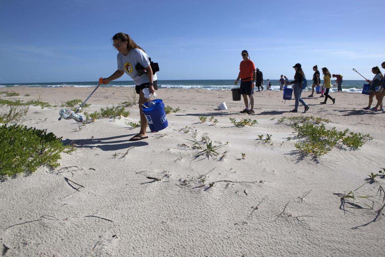
About 50 participants led by NASA Kennedy Space Center's Employee Resource Groups picked up about 20 bags of trash and other large debris along the center's shoreline before turtle-nesting season as a community service. Sea turtle-nesting season begins in about one month. Unlike what might be found along a public beach, all of the debris that litters Kennedy’s restricted beaches washes ashore after being discarded at sea. Of the 72 miles of beach that form the eastern boundary of Brevard County, Florida, about six of those miles line Kennedy.
About 50 participants led by NASA Kennedy Space Center's Employee Resource Groups picked up about 20 bags of trash and other large debris along the center's shoreline before turtle-nesting season as a community service. Sea turtle-nesting season begins in about one month. Unlike what might be found along a public beach, all of the debris that litters Kennedy’s restricted beaches washes ashore after being discarded at sea. Of the 72 miles of beach that form the eastern boundary of Brevard County, Florida, about six of those miles line Kennedy.
About 50 participants led by NASA Kennedy Space Center's Employee Resource Groups picked up about 20 bags of trash and other large debris along the center's shoreline before turtle-nesting season as a community service. Sea turtle-nesting season begins in about one month. Unlike what might be found along a public beach, all of the debris that litters Kennedy’s restricted beaches washes ashore after being discarded at sea. Of the 72 miles of beach that form the eastern boundary of Brevard County, Florida, about six of those miles line Kennedy.
About 50 participants led by NASA Kennedy Space Center's Employee Resource Groups picked up about 20 bags of trash and other large debris along the center's shoreline before turtle-nesting season as a community service. Sea turtle-nesting season begins in about one month. Unlike what might be found along a public beach, all of the debris that litters Kennedy’s restricted beaches washes ashore after being discarded at sea. Of the 72 miles of beach that form the eastern boundary of Brevard County, Florida, about six of those miles line Kennedy.
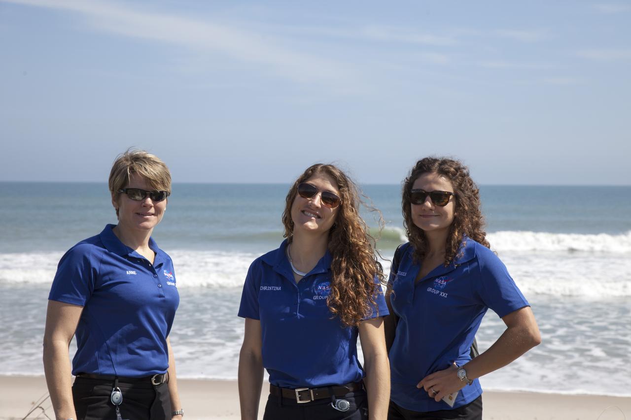
CAPE CANAVERAL, Fla. - NASA astronaut candidates, from left, Anne McClain, Christina Hammock and Jessica Meir stand on the beach overlooking the Atlantic Ocean at the Beach House at NASA's Kennedy Space Center. The Beach House is a traditional gathering place for astronauts before they fly into space. The astronaut class of 2013 was selected by NASA after an extensive year-and-a-half search. The new group will help the agency push the boundaries of exploration and travel to new destinations in the solar system. To learn more about the astronaut class of 2013, visit: http://www.nasa.gov/astronauts/2013astroclass.html Photo credit: NASA/Daniel Casper
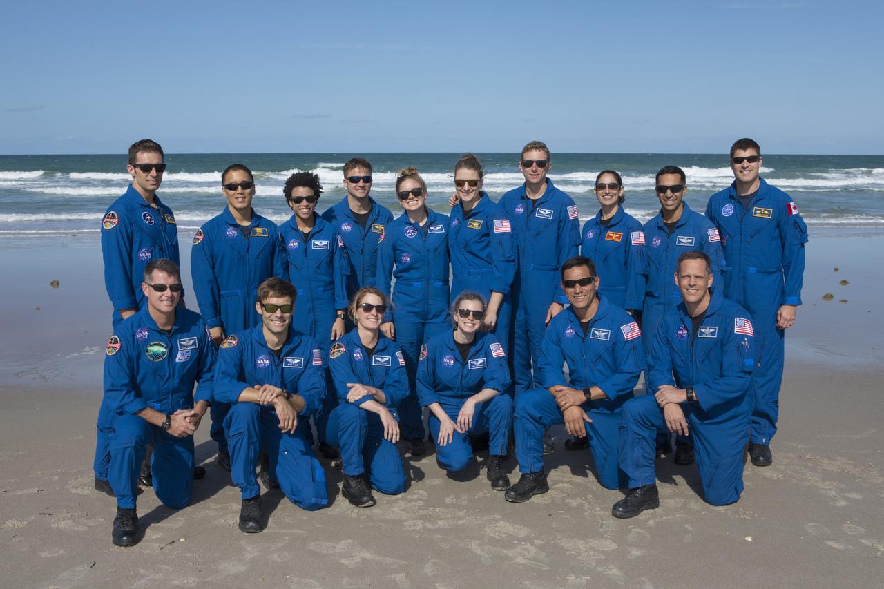
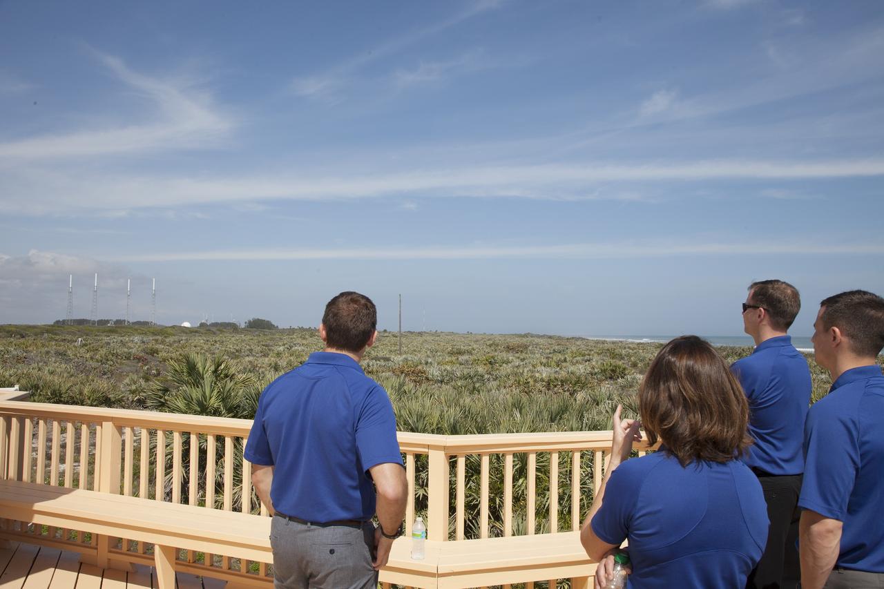
Members of the 2017 class of astronaut candidates pause for a group photo on the beach after a familiarization tour of the Beach House at NASA's Kennedy Space Center in Florida. The candidates toured center facilities, including the Vehicle Assembly Building, Launch Control Center, Neil Armstrong Operations and Checkout Building high bay, Launch Pad 39B and the Space Station Processing Facility. They also toured Boeing's Commercial Crew and Cargo Facility, United Launch Alliance's Space Launch Complex 41 at Cape Canaveral Air Force Station, and SpaceX's Launch Pad 39A at Kennedy. The candidates will spend about two years getting to know the space station systems and learning how to spacewalk, speak Russian, control the International Space Station's robotic arm and fly T-38s, before they're eligible to be assigned to a mission.
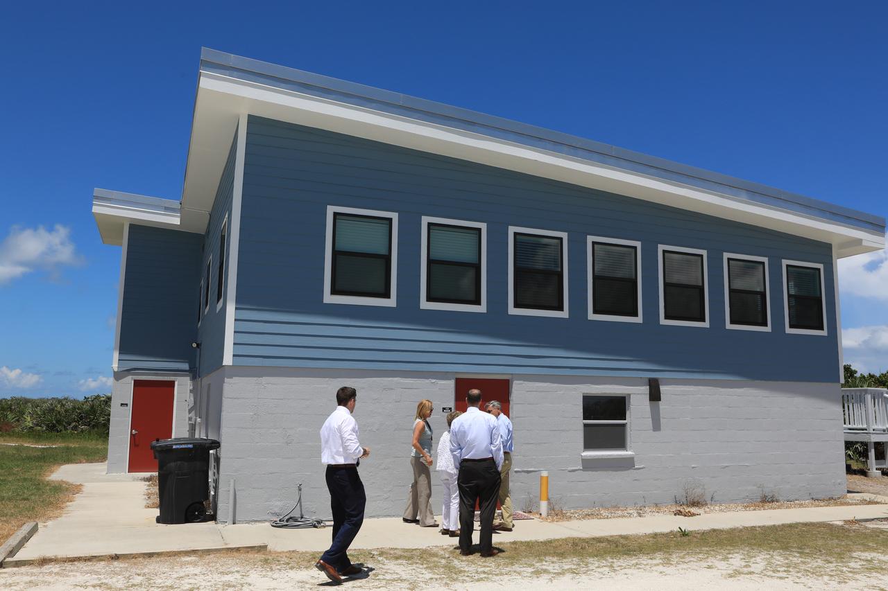
NASA Administrator Jim Bridenstine is given a tour of the Kennedy Space Center's ocean-side Beach House. The work to restore the conference center was recently completed following damage by Hurricane Matthew in October 2016. Bridenstine made his first official visit to the Florida spaceport on Aug. 6 and 7, 2018.
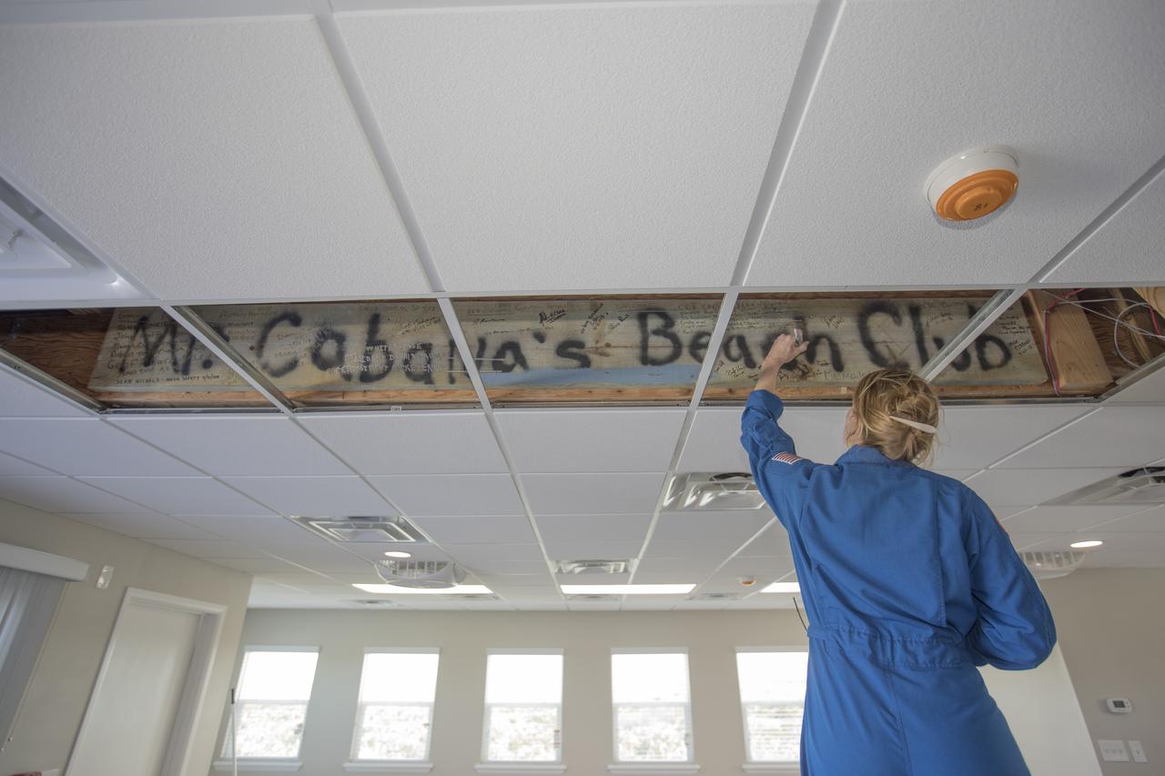
A members of the 2017 class of astronaut candidates signs her name to a wooden sign inside the Beach House during a familiarization tour at NASA's Kennedy Space Center in Florida. The candidates toured center facilities, including the Vehicle Assembly Building, Launch Control Center, Neil Armstrong Operations and Checkout Building high bay, Launch Pad 39B and the Space Station Processing Facility. They also toured Boeing's Commercial Crew and Cargo Facility, United Launch Alliance's Space Launch Complex 41 at Cape Canaveral Air Force Station, and SpaceX's Launch Pad 39A at Kennedy. The candidates will spend about two years getting to know the space station systems and learning how to spacewalk, speak Russian, control the International Space Station's robotic arm and fly T-38s, before they're eligible to be assigned to a mission.
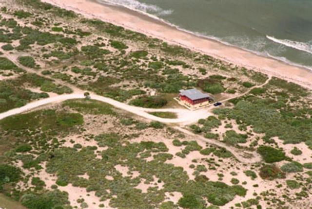
An aerial view focuses on the Beach House, a site for meetings on the Center. It sits south of Launch Complex 39 and Complex 41, near Phillips Parkway, which runs parallel to the Atlantic Ocean.
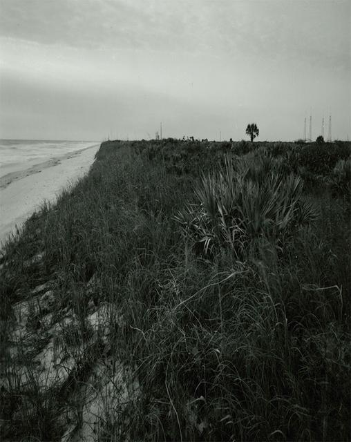
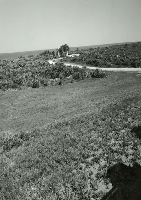
View Along Beach in Front of Beach House (KSC Center Director's Conference Center)
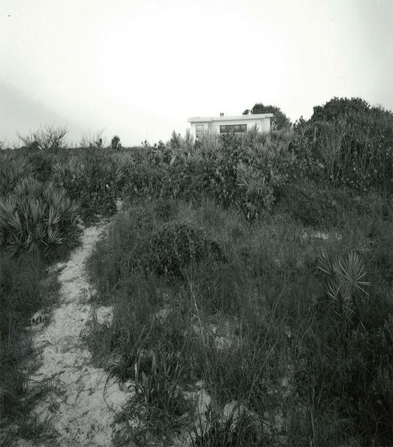
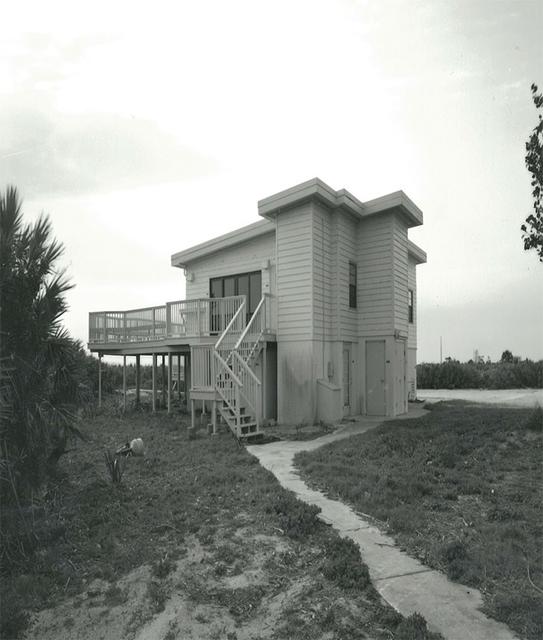
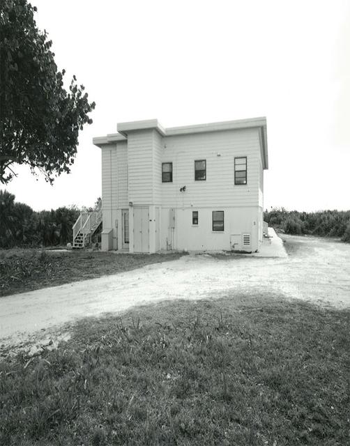
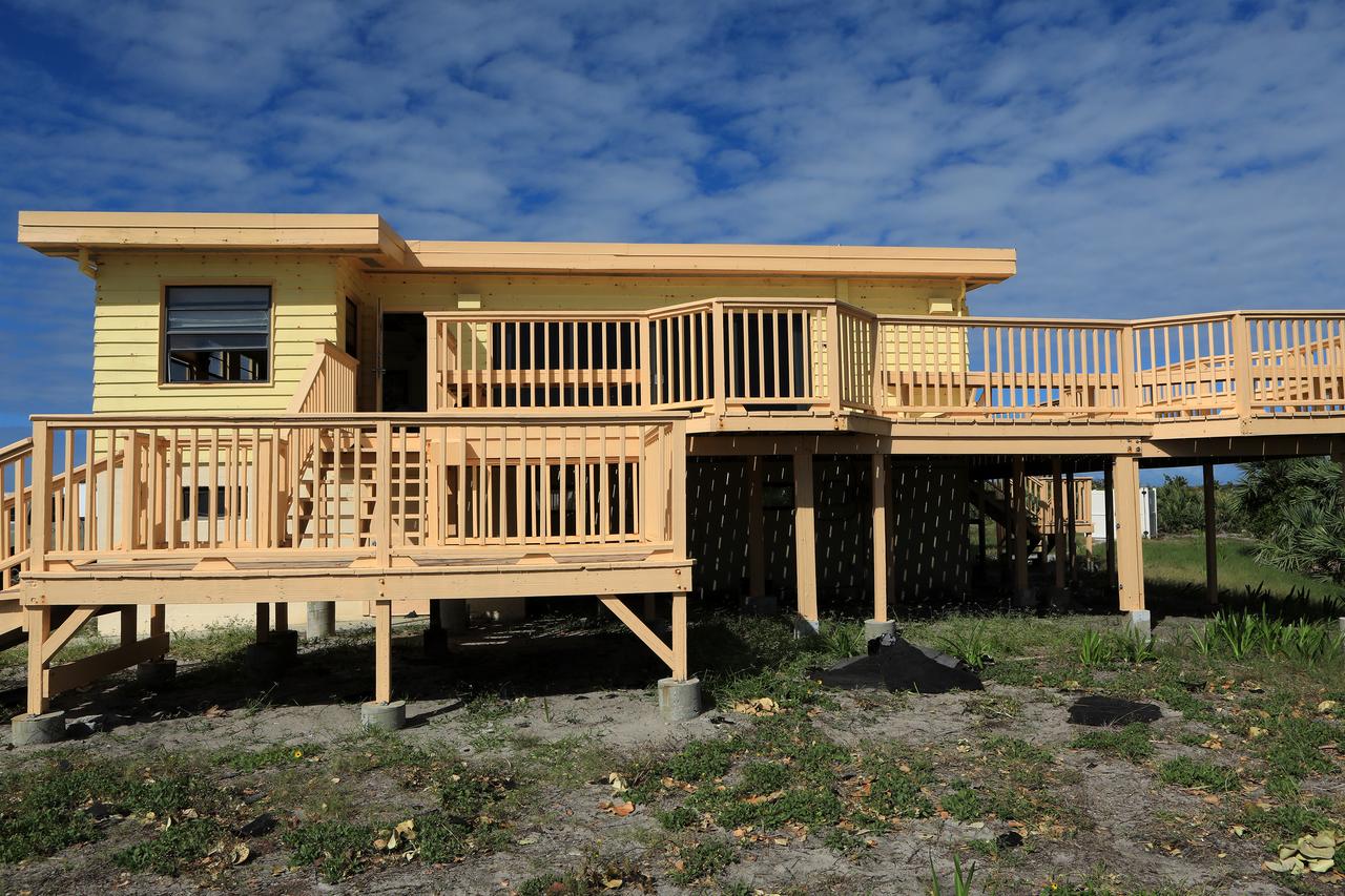
Exterior View of Beach House (KSC Center Director's Conference Center)
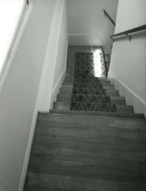
Interior View of Beach House (KSC Center Director's Conference Center)
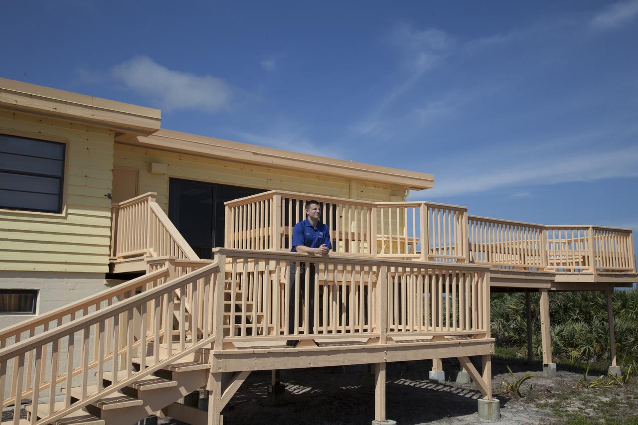
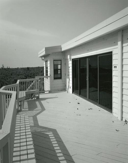
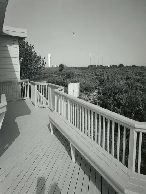
View from Deck of Beach House (KSC Center Director's Conference Center)
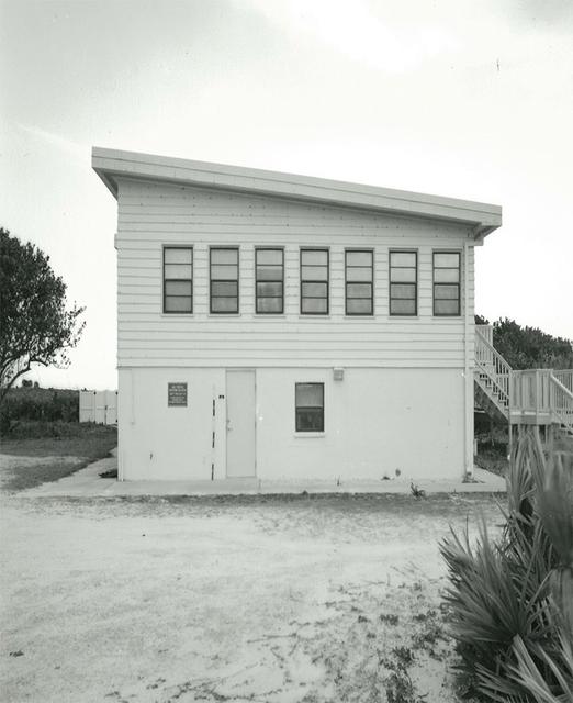
Exterior View of Beach House (KSC Center Director's Conference Center)
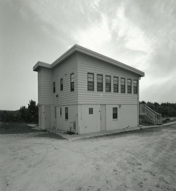
Exterior View of Beach House (KSC Center Director's Conference Center)
View from Deck of Beach House (KSC Center Director's Conference Center)
Interior View of Beach House (KSC Center Director's Conference Center)
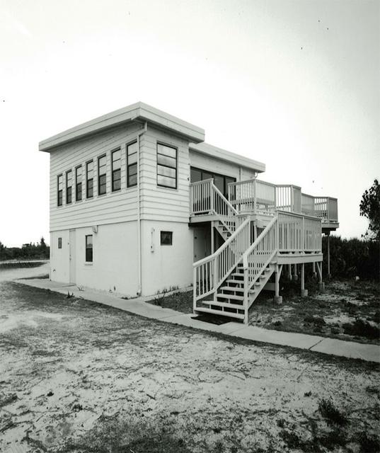
Exterior View of Beach House (KSC Center Director's Conference Center)
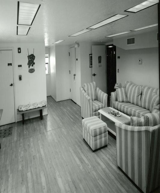
Interior View of Beach House (KSC Center Director's Conference Center)
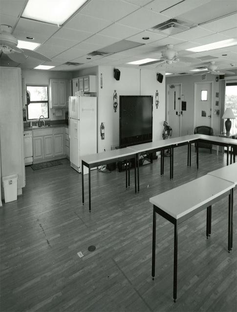
Interior View of Beach House (KSC Center Director's Conference Center)
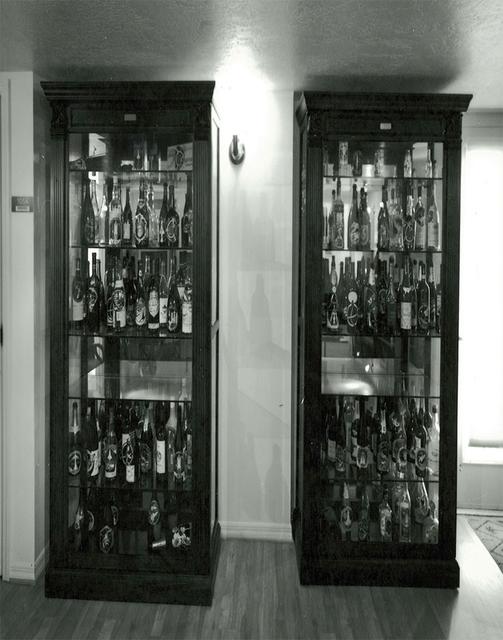
Interior View of Beach House (KSC Center Director's Conference Center)
Exterior View of Beach House (KSC Center Director's Conference Center)
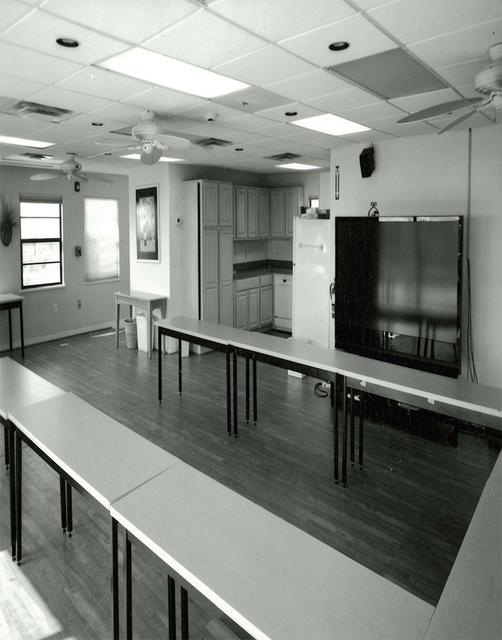
Interior View of Beach House (KSC Center Director's Conference Center)
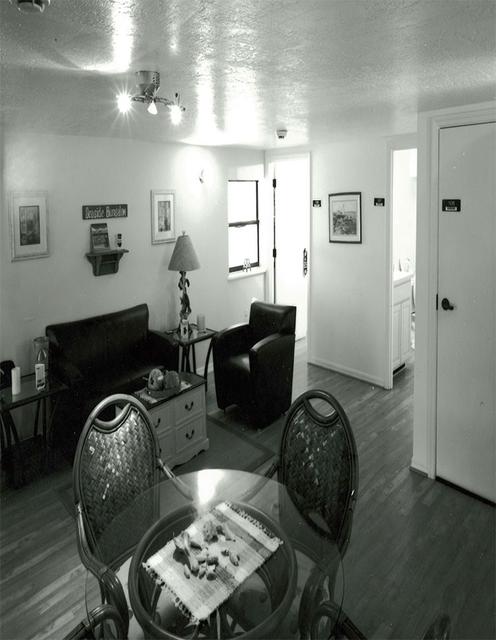
Interior View of Beach House (KSC Center Director's Conference Center)
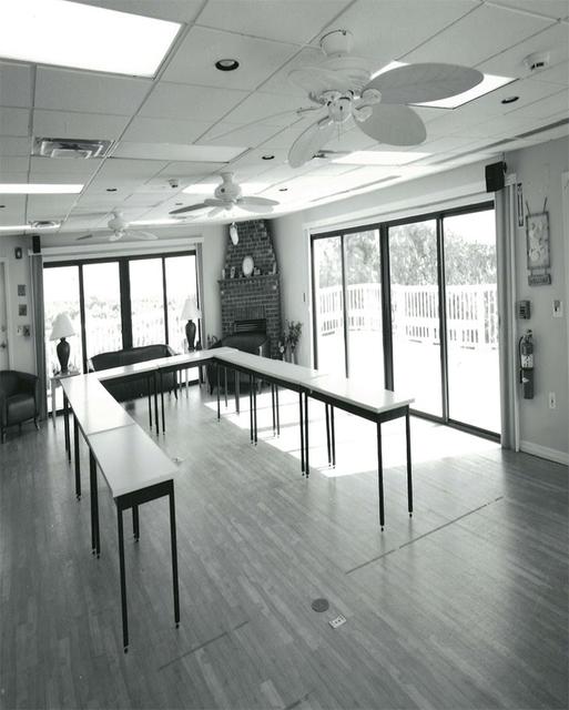
Interior View of Beach House (KSC Center Director's Conference Center)
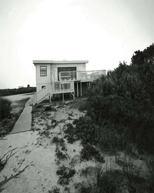
Exterior View of Beach House (KSC Center Director's Conference Center)
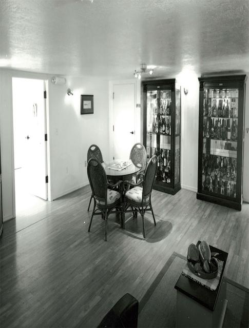
Interior View of Beach House (KSC Center Director's Conference Center)
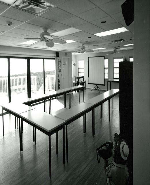
Interior View of Beach House (KSC Center Director's Conference Center)
Interior View of Beach House (KSC Center Director's Conference Center)
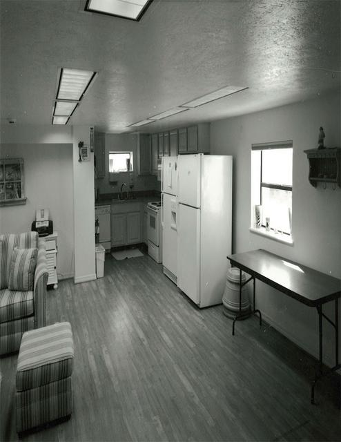
Interior View of Beach House (KSC Center Director's Conference Center)
Roofing materials, blown loose by Hurricane Matthew, lie on the ground behind the Beach House at NASA’s Kennedy Space Center in Florida. Members of the Disaster Assessment and Recovery Team (DART) are working on repairs to the facility following Hurricane Matthew, which passed to the east of Kennedy on Oct. 6 and 7, 2016. The center received some isolated roof damage, damaged support buildings, a few downed power lines, and limited water intrusion. Beach erosion also occurred, although the storm surge was less than expected.
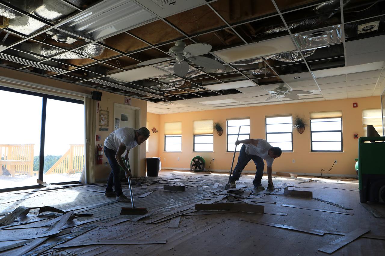
Members of the Disaster Assessment and Recovery Team (DART) work on flooring repairs to the Beach House at NASA’s Kennedy Space Center in Florida. The effort is part of the spaceport’s ongoing recovery from Hurricane Matthew, which passed to the east of Kennedy on Oct. 6 and 7, 2016. The center received some isolated roof damage, damaged support buildings, a few downed power lines, and limited water intrusion. Beach erosion also occurred, although the storm surge was less than expected.
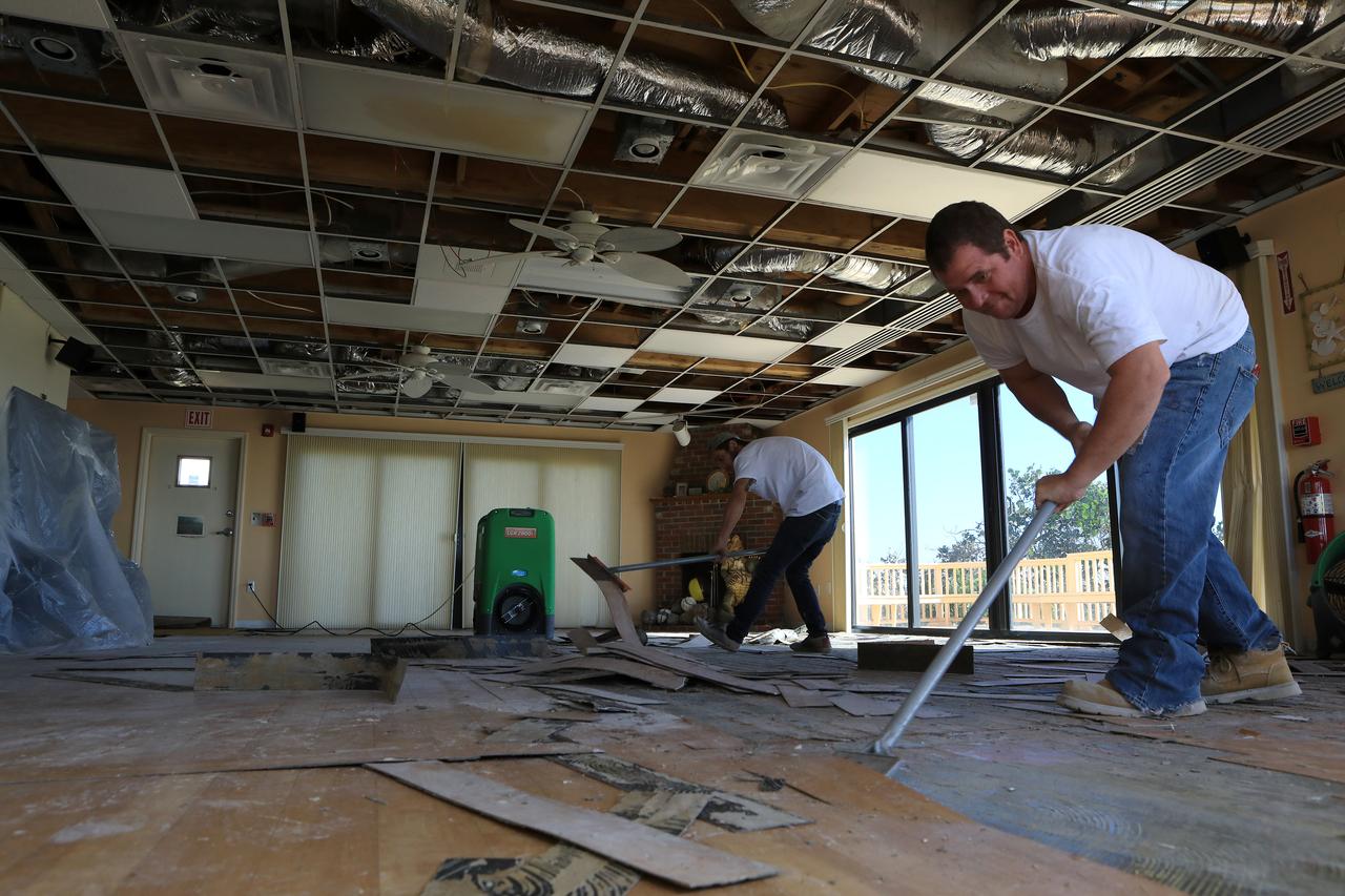
Members of the Disaster Assessment and Recovery Team (DART) work on flooring repairs to the Beach House at NASA’s Kennedy Space Center in Florida. The effort is part of the spaceport’s ongoing recovery from Hurricane Matthew, which passed to the east of Kennedy on Oct. 6 and 7, 2016. The center received some isolated roof damage, damaged support buildings, a few downed power lines, and limited water intrusion. Beach erosion also occurred, although the storm surge was less than expected.
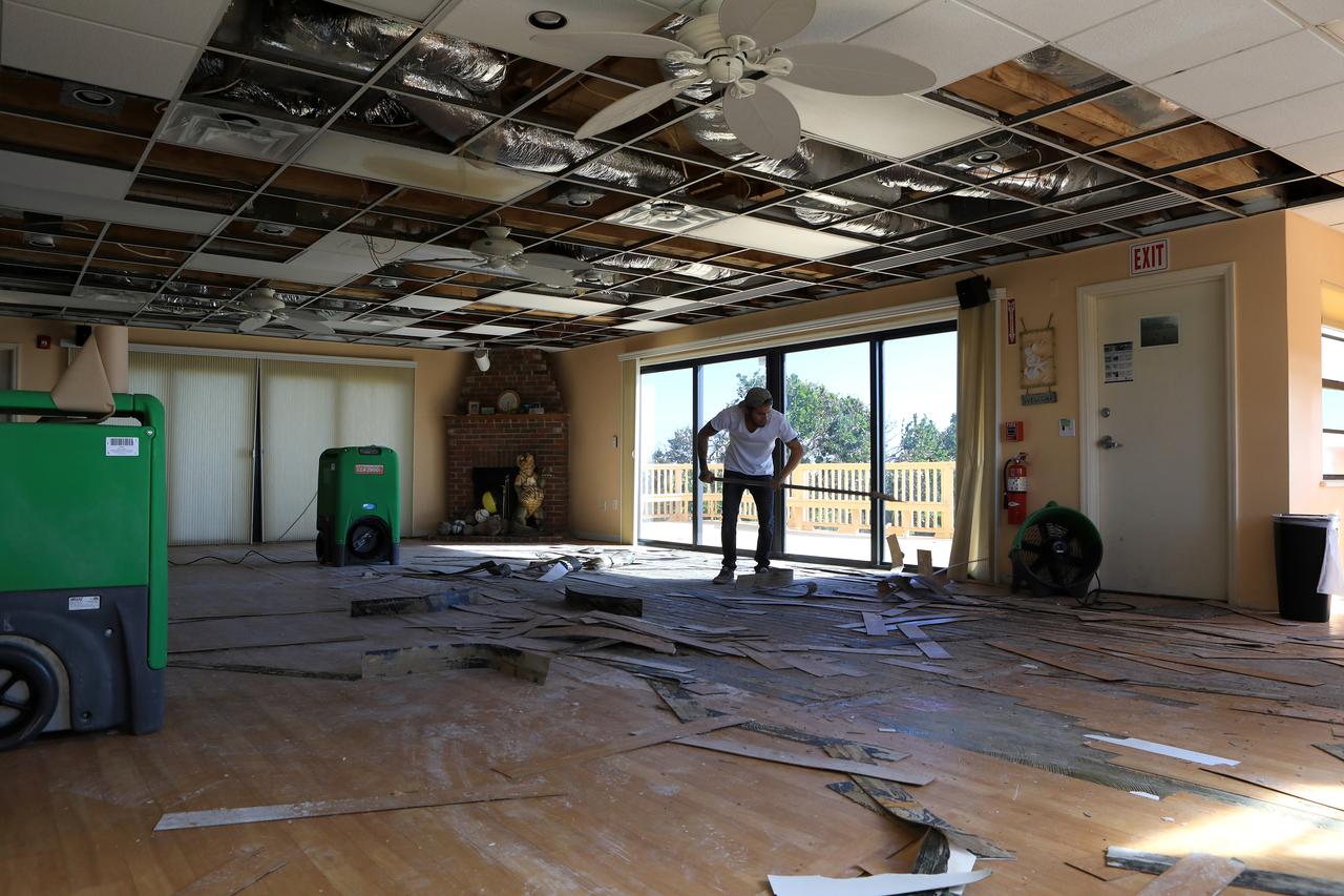
Members of the Disaster Assessment and Recovery Team (DART) work on flooring repairs to the Beach House at NASA’s Kennedy Space Center in Florida. The effort is part of the spaceport’s ongoing recovery from Hurricane Matthew, which passed to the east of Kennedy on Oct. 6 and 7, 2016. The center received some isolated roof damage, damaged support buildings, a few downed power lines, and limited water intrusion. Beach erosion also occurred, although the storm surge was less than expected.
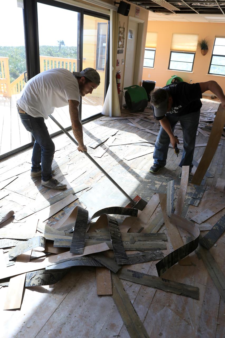
Members of the Disaster Assessment and Recovery Team (DART) work on flooring repairs to the Beach House at NASA’s Kennedy Space Center in Florida. The effort is part of the spaceport’s ongoing recovery from Hurricane Matthew, which passed to the east of Kennedy on Oct. 6 and 7, 2016. The center received some isolated roof damage, damaged support buildings, a few downed power lines, and limited water intrusion. Beach erosion also occurred, although the storm surge was less than expected.
Roofing materials, blown loose by Hurricane Matthew, are visible on the ground below the deck of the Beach House at NASA’s Kennedy Space Center in Florida. Members of the Disaster Assessment and Recovery Team (DART) are working on repairs to the facility following Hurricane Matthew, which passed to the east of Kennedy on Oct. 6 and 7, 2016. The center received some isolated roof damage, damaged support buildings, a few downed power lines, and limited water intrusion. Beach erosion also occurred, although the storm surge was less than expected.
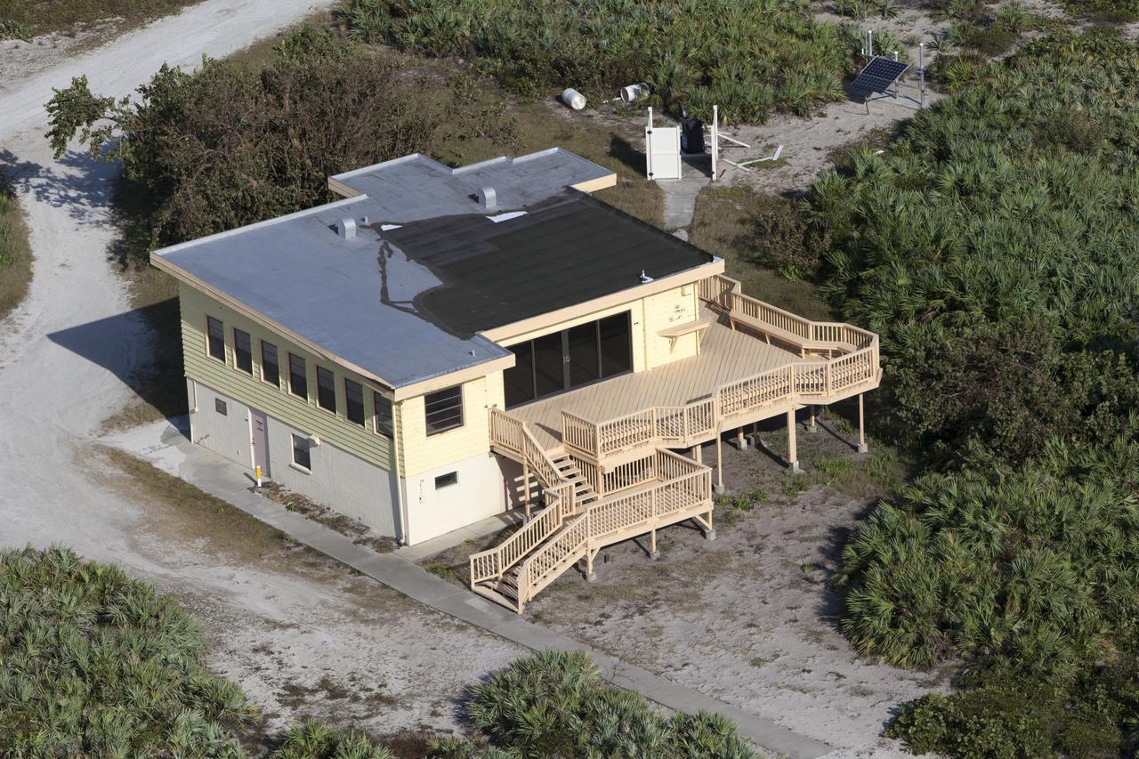
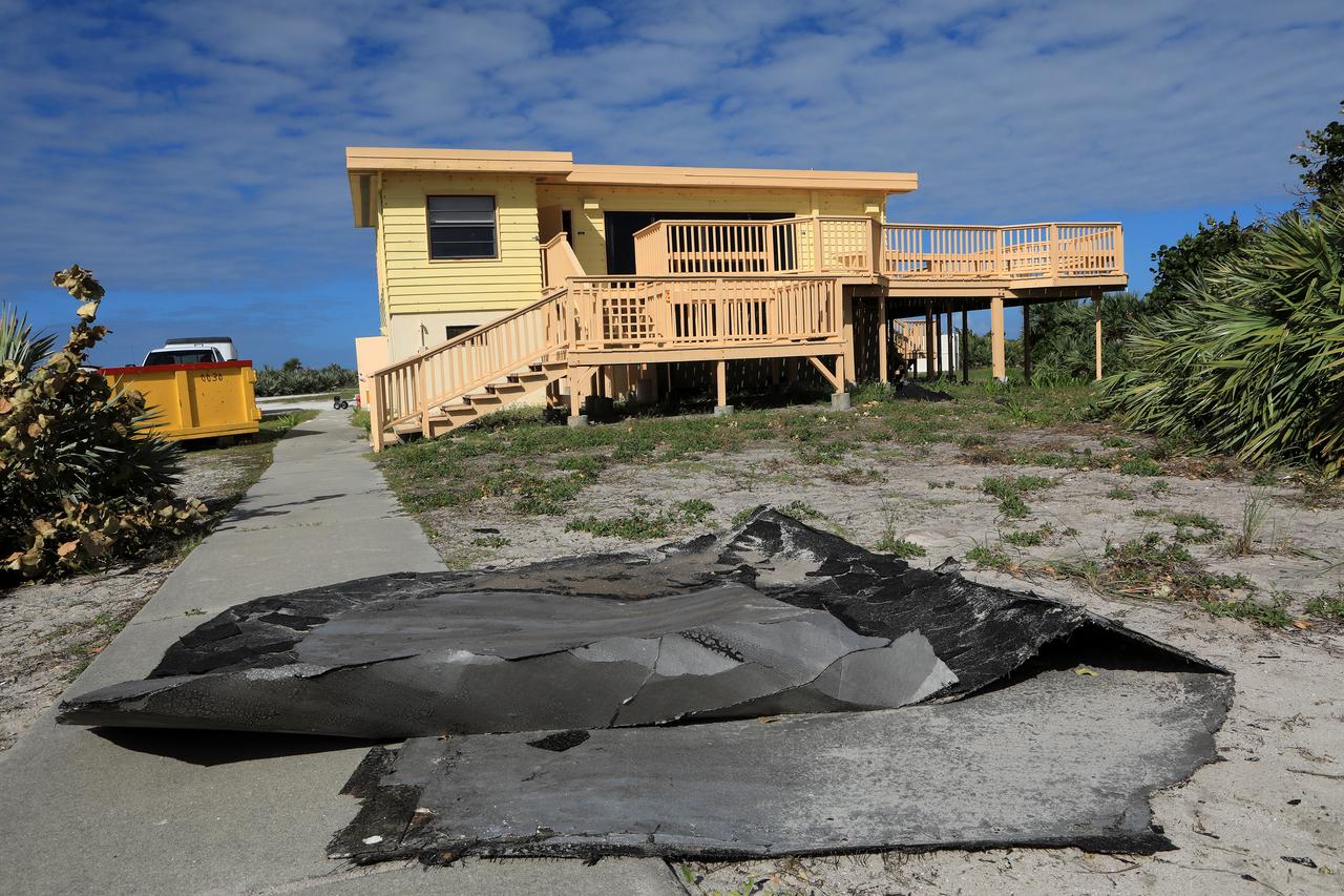
The Beach House is seen during an aerial survey of NASA's Kennedy Space Center in Florida on September 12, 2017. The survey was performed to identify structures and facilities that may have sustained damage from Hurricane Irma as the storm passed Kennedy on September 10, 2017. NASA closed the center ahead of the storm's onset and only a small team of specialists known as the Rideout Team was on the center as the storm approached and passed.
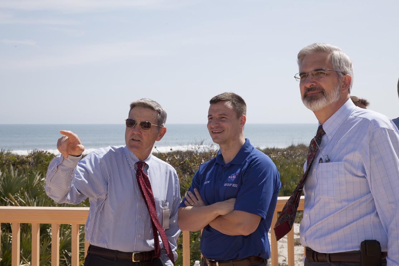
CAPE CANAVERAL, Fla. – Bob Cabana, director of NASA's Kennedy Space Center and a former space shuttle commander, points out landmarks of the space center to astronaut candidate Andrew Morgan during a visit to the Beach House at Kennedy. The Beach House is a traditional gathering place for astronauts before they fly into space. The astronaut class of 2013 was selected by NASA after an extensive year-and-a-half search. The new group will help the agency push the boundaries of exploration and travel to new destinations in the solar system. To learn more about the astronaut class of 2013, visit: http://www.nasa.gov/astronauts/2013astroclass.html Photo credit: NASA/Daniel Casper
CAPE CANAVERAL, Fla. - NASA astronaut candidates, from left, Josh Cassada, Nicole Mann, Tyler "Nick" Hague and Andrew Morgan look out on Kennedy Space Center at the Beach House. The Beach House is a traditional gathering place for astronauts before they fly into space. The astronaut class of 2013 was selected by NASA after an extensive year-and-a-half search. The new group will help the agency push the boundaries of exploration and travel to new destinations in the solar system. To learn more about the astronaut class of 2013, visit: http://www.nasa.gov/astronauts/2013astroclass.html Photo credit: NASA/Daniel Casper
KENNEDY SPACE CENTER, FLA. - At the Beach House, Deputy Director Woodrow Whitlow Jr. greets Glenn Vera, with Florida Spaceport Authority. The two joined Congressman Tom Feeney who concluded his walks along the entire coastline of Florida’s 24th District March 1 on the beach at Kennedy Space Center. During his walks, he met with constituents and community leaders to discuss legislative issues that will be addressed by the 108th Congress.
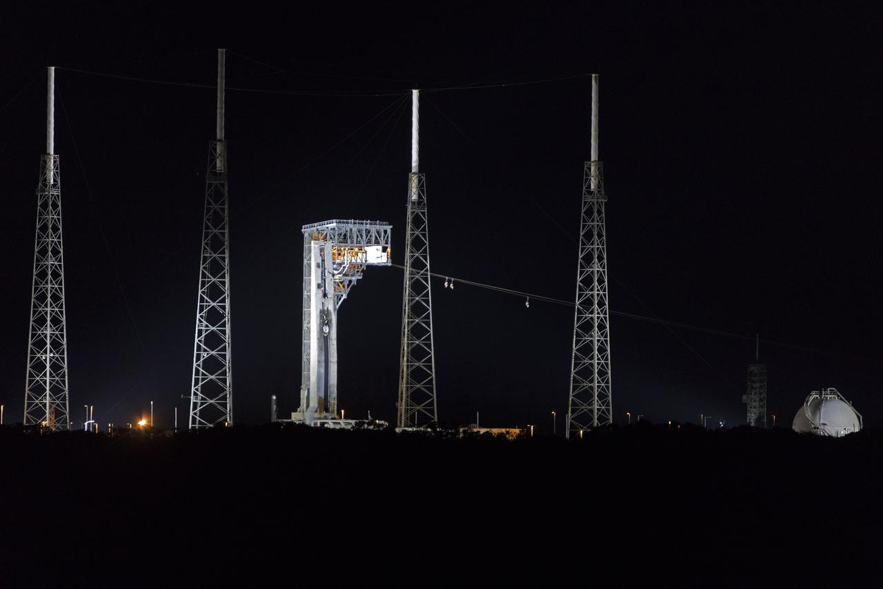
Boeing and United Launch Alliance (ULA) conducted an emergency egress system demonstration with Commercial Crew astronauts at Cape Canaveral Air Force Station’s Launch Complex 41 in Florida on June 19, 2018. The Boeing CST-100 Starliner will launch on a ULA Atlas V rocket, carrying astronauts to the International Space Station. The emergency egress system will allow for a safe evacuation in the unlikely event of an emergency on the launch pad.
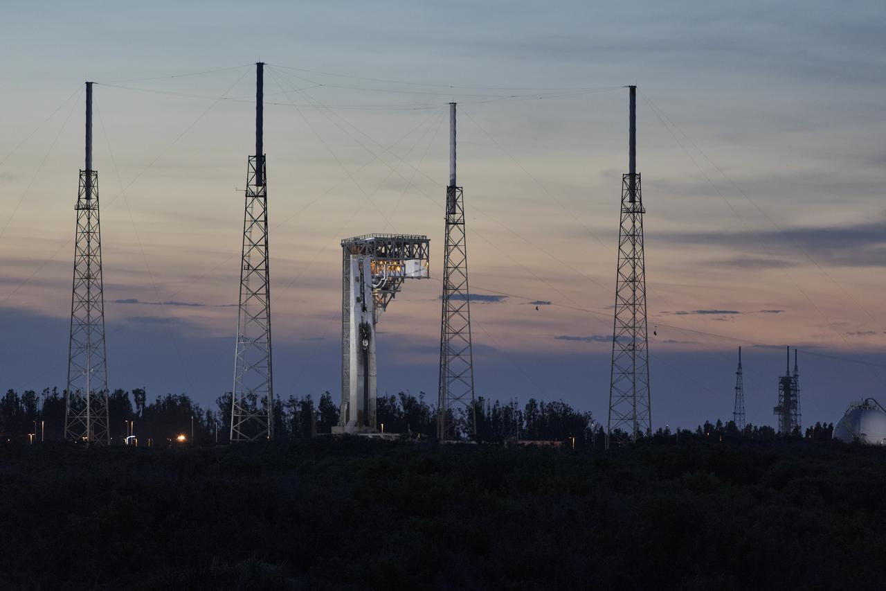
Commercial Crew astronauts participate in a Boeing/United Launch Alliance (ULA) emergency egress system demonstration at Cape Canaveral Air Force Station’s Launch Complex 41 in Florida on June 19, 2018. The emergency egress system will allow for a safe evacuation in the unlikely event of an emergency on the launch pad on launch day. It can carry up to 20 people more than 1,300 feet away from the crew access tower and the launch vehicle. The Boeing CST-100 Starliner will launch on a ULA Atlas V rocket, carrying astronauts to the International Space Station.
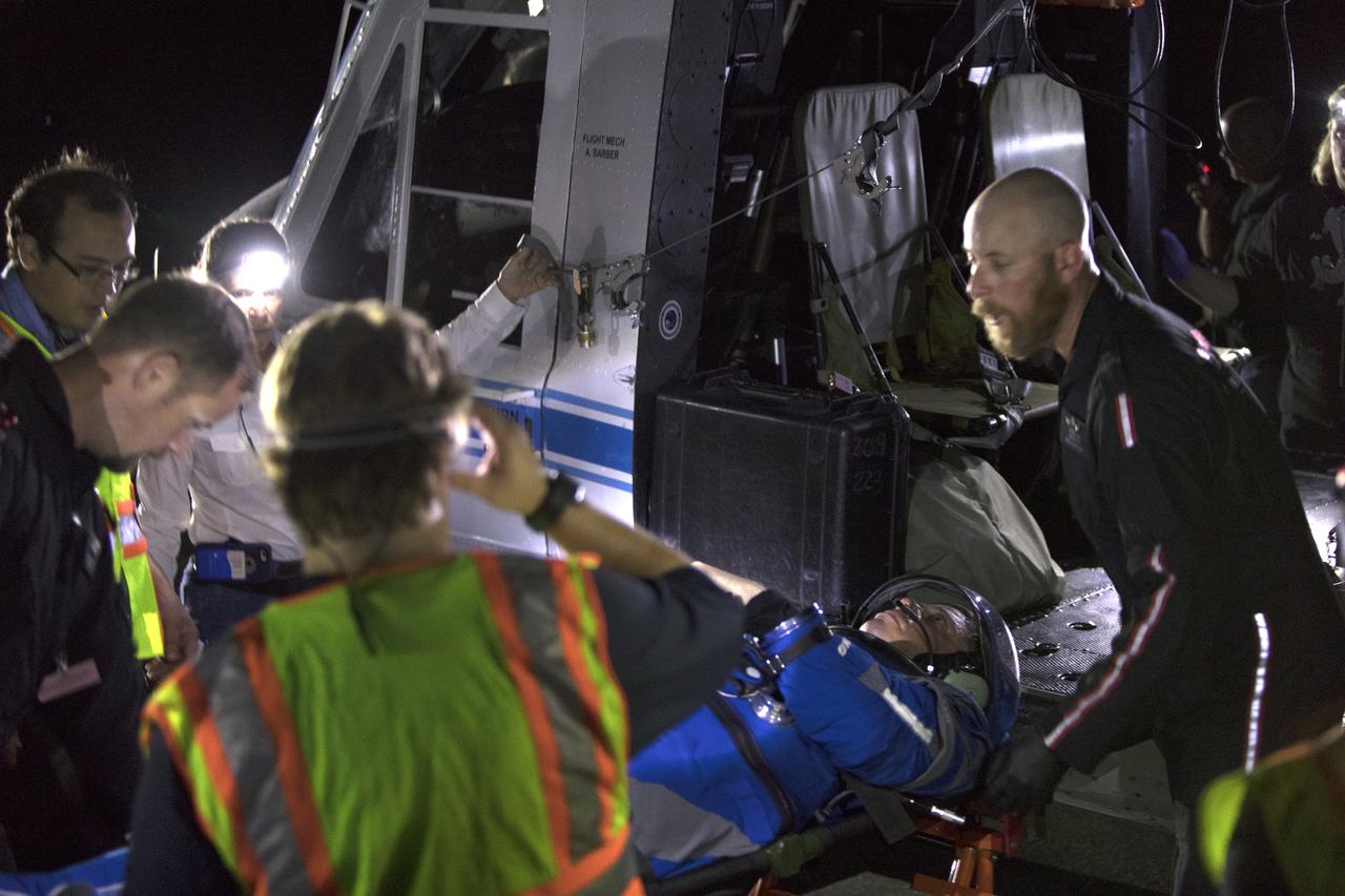
A Commercial Crew astronaut participates in a Boeing/United Launch Alliance emergency egress system demonstration at Cape Canaveral Air Force Station’s Launch Complex 41 in Florida on June 19, 2018. The system features seats attached to slide wires which would carry astronauts and ground crew more than 1,300 feet away from the crew access tower in the unlikely event of an emergency prior to liftoff.
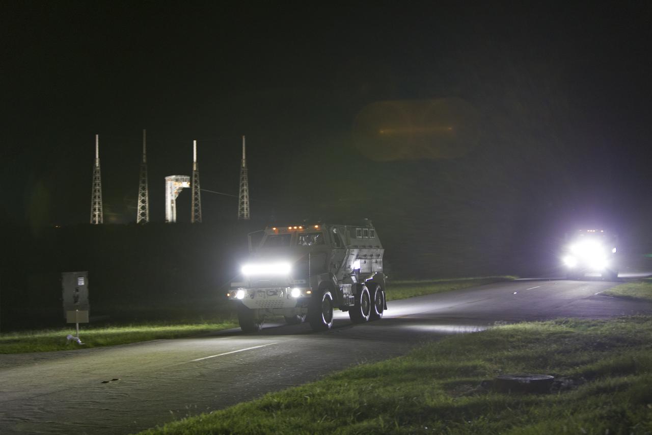
Originally designed for military applications, NASA’s mine-resistant ambush protected vehicles, or MRAPs, will be used in the unlikely event of an emergency at the launch pad prior to liftoff. The vehicles, seen here during a Boeing/United Launch Alliance emergency egress system demonstration at Cape Canaveral Air Force Station’s Launch Complex 41 in Florida on June 19, 2018, offer a mobile bunker for astronauts and ground crews, should they need to get away from the launch pad quickly in an emergency.
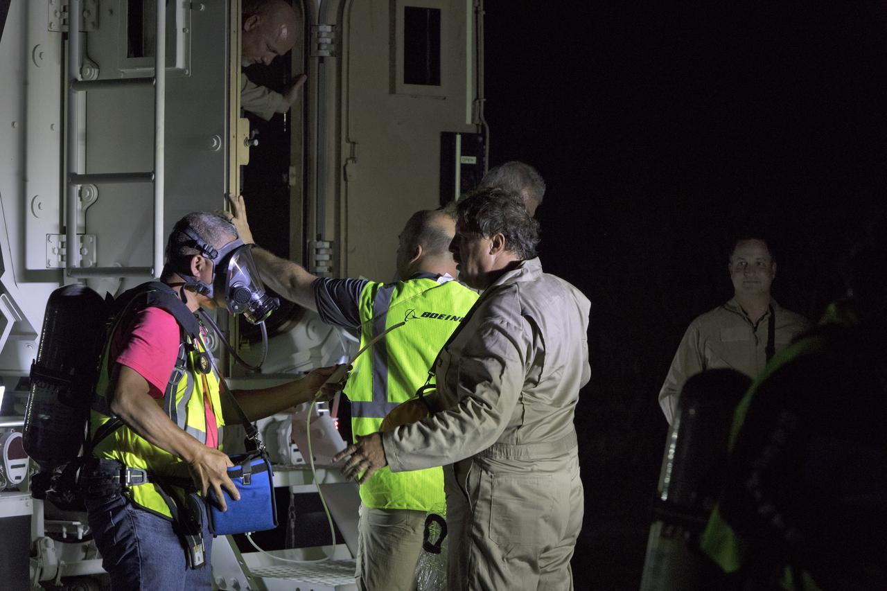
Boeing and United Launch Alliance (ULA) conducted an emergency egress system demonstration at Cape Canaveral Air Force Station’s Launch Complex 41 in Florida on June 19, 2018. The emergency egress system will allow for a safe evacuation in the unlikely event of an emergency on the launch pad on launch day. The Boeing CST-100 Starliner will launch on a ULA Atlas V rocket, carrying astronauts to the International Space Station.
Commercial Crew astronauts test out the Boeing/United Launch Alliance (ULA) emergency egress system on June 19, 2018, at Cape Canaveral Air Force Station’s Launch Complex 41 in Florida. The emergency egress system provides an escape route in the unlikely event of an emergency prior to liftoff on launch day. It will be in place when Boeing’s CST-100 Starliner, launched aboard a ULA Atlas V rocket, carries astronauts to the International Space Station.
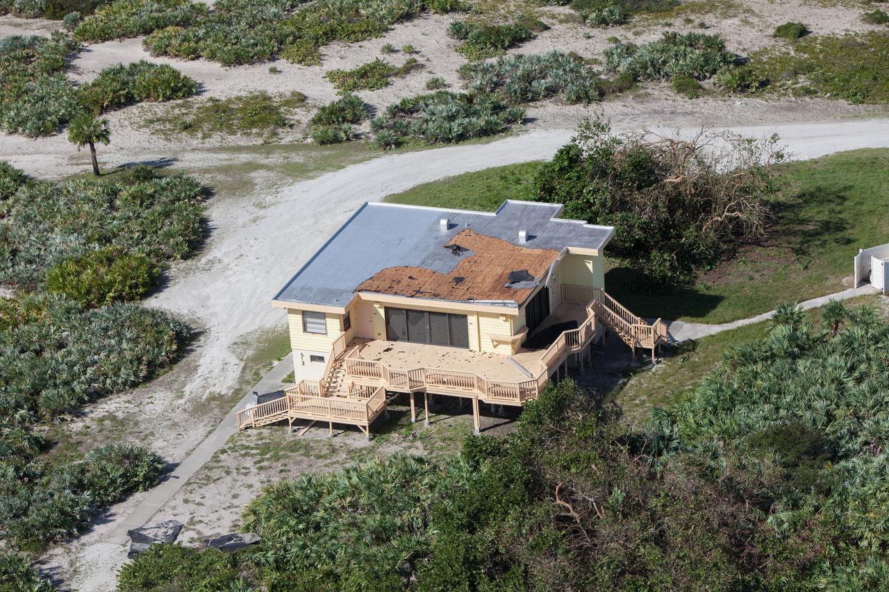
The Beach House is seen during an aerial survey of NASA's Kennedy Space Center in Florida on Saturday. The survey was performed to identify structures and facilities that may have sustained damage from Hurricane Matthew as the storm passed to the east of Kennedy on Oct. 6 and 7, 2016. Officials determined that the center received some isolated roof damage, damaged support buildings, a few downed power lines, and limited water intrusion. Beach erosion also occurred, although the storm surge was less than expected. NASA closed the center ahead of the storm’s onset and only a small team of specialists known as the Rideout Team was on the center as the storm approached and passed
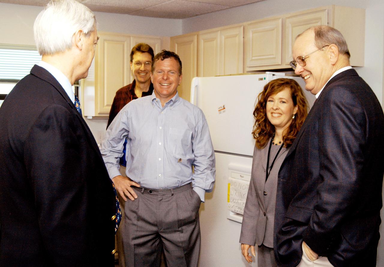
KENNEDY SPACE CENTER, FLA. - At the Beach House, Congressman Tom Feeney (center) relaxes after his walk on Brevard County’s beach north of the launch pads. With him are William Sample (left), president of Space Gateway Support at KSC; Stan Starr, with Dynamac Corp.; Lisa Malone, director of External Affairs at KSC; and Jim Hattaway, associate director of KSC. During January and February, Congressman Feeney traveled the entire coastline of Florida’s 24th District, and concluded his walks March 1 in Brevard County. On his walks, he met with constituents and community leaders to discuss legislative issues that will be addressed by the 108th Congress.
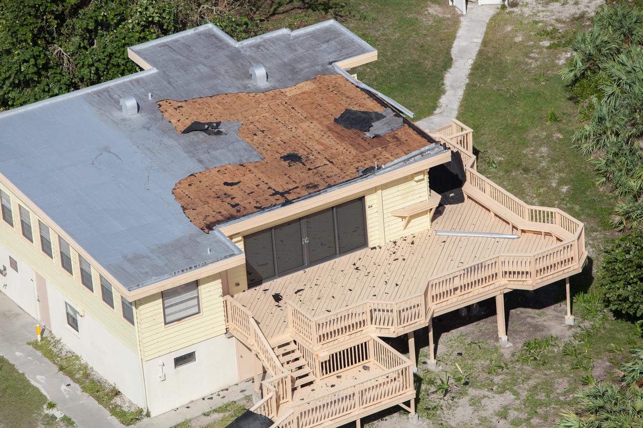
The Beach House is seen during an aerial survey of NASA's Kennedy Space Center in Florida on Saturday. The survey was performed to identify structures and facilities that may have sustained damage from Hurricane Matthew as the storm passed to the east of Kennedy on Oct. 6 and 7, 2016. Officials determined that the center received some isolated roof damage, damaged support buildings, a few downed power lines, and limited water intrusion. Beach erosion also occurred, although the storm surge was less than expected. NASA closed the center ahead of the storm’s onset and only a small team of specialists known as the Rideout Team was on the center as the storm approached and passed.
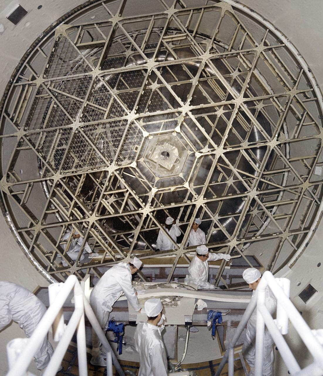
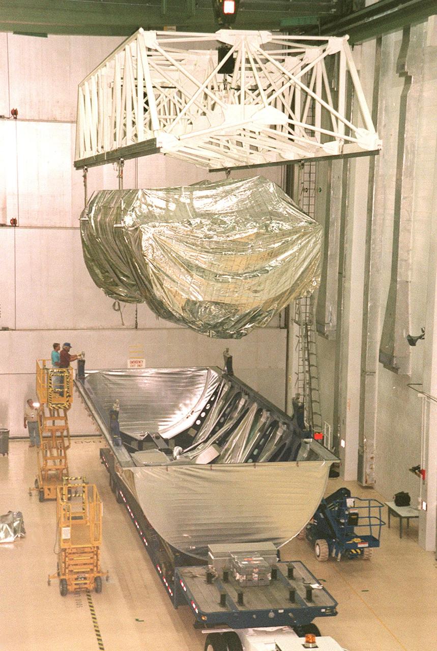
This photograph was taken during installation of floor grids on the upper and lower floors inside the Skylab Orbital Workshop at the McDornell Douglas plant at Huntington Beach, California. The OWS was divided into two major compartments. The lower level provided crew accommodations for sleeping, food preparation and consumption, hygiene, waste processing and disposal, and performance of certain experiments. The upper level consisted of a large work area and housed water storage tanks, a food freezer, storage vaults for film, scientific airlocks, mobility and stability experiment equipment, and other experimental equipment.
KENNEDY SPACE CENTER, FLA. - At the Beach House, Congressman Tom Feeney (right) talks with Glenn Vera (left), with Florida Spaceport Authority, and Stan Starr (center), with Dynamac Corp. During January and February, Congressman Feeney traveled the entire coastline of Florida’s 24th District, and concluded his walks March 1 in Brevard County. On his walks, he met with constituents and community leaders to discuss legislative issues that will be addressed by the 108th Congress.
KENNEDY SPACE CENTER, FLA. - At the Beach House, Congressman Tom Feeney (left) talks with Jim Hattaway, associate director of KSC. During January and February, Congressman Feeney traveled the entire coastline of Florida’s 24th District, and concluded his walks March 1 in Brevard County. On his walks, he met with constituents and community leaders to discuss legislative issues that will be addressed by the 108th Congress.
KENNEDY SPACE CENTER, FLA. - At the Beach House, Congressman Tom Feeney (right) greets William Sample, president of Space Gateway Support. During January and February, Congressman Feeney traveled the entire coastline of Florida’s 24th District, and concluded his walks March 1 in Brevard County. On his walks, he met with constituents and community leaders to discuss legislative issues that will be addressed by the 108th Congress.
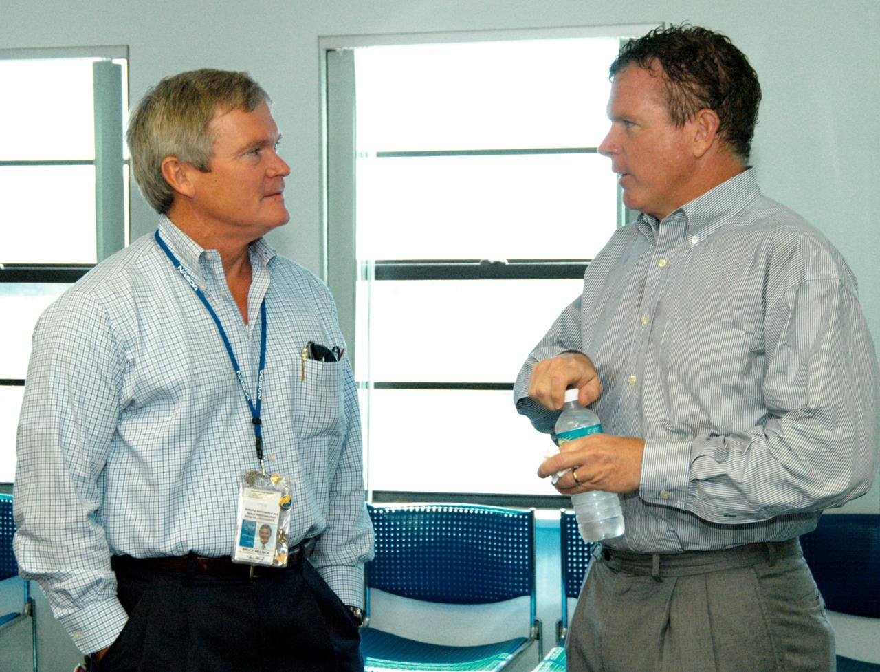
KENNEDY SPACE CENTER, FLA. - At the Beach House, Congressman Tom Feeney (right) talks with Bruce Melnick (left), vice president for Boeing Florida Operations at KSC. Feeney conducted a walk down the coastline of Florida’s 24th District on several days during January and February, concluding March 1 at Kennedy Space Center. On his walks, Feeney met with constituents and community leaders to discuss legislative issues that will be addressed by the 108th Congress.
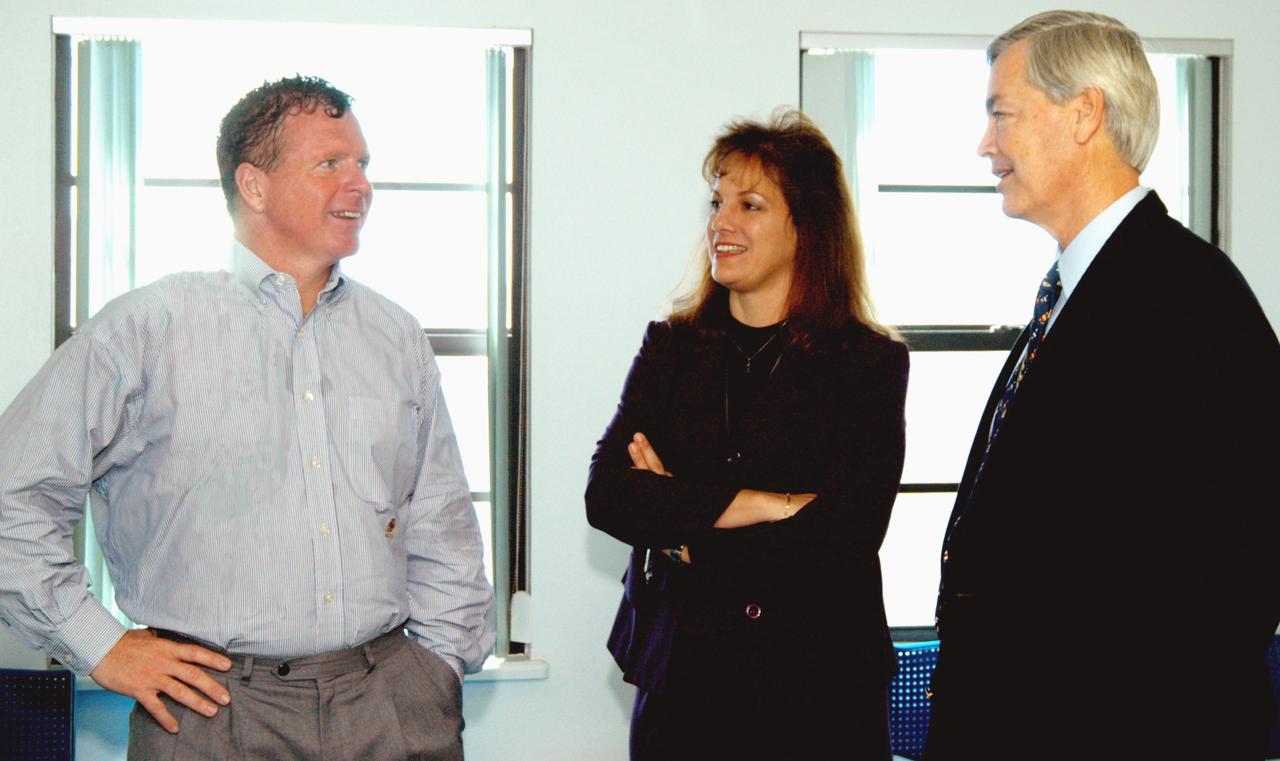
KENNEDY SPACE CENTER, FLA. - At the Beach House, Congressman Tom Feeney (left) talks with William Sample (right), president of Space Gateway Support. In the center is the Congressman’s wife, Ellen. During January and February, Congressman Feeney traveled the entire coastline of Florida’s 24th District, and concluded his walks March 1 in Brevard County. On his walks, he met with constituents and community leaders to discuss legislative issues that will be addressed by the 108th Congress.
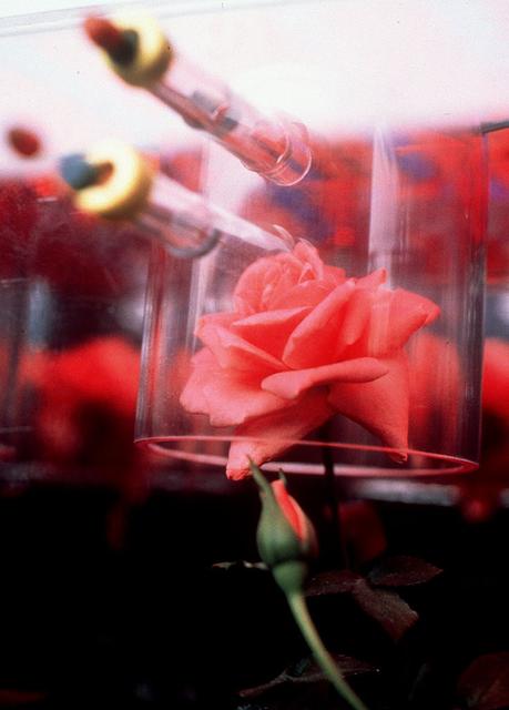
International Flavors and Fragrances Inc., is a company that creates and manufactures flavors, fragrances and aroma chemicals. The Overnight Scentsation rose plant will be housed aboard NASA's shuttle flight STS-95 in a specially-designed structure under ultraviolet lights. The flowering plant was brought to Cape Canaveral from its home at IFF's greenhouse in Union Beach, New Jersey.
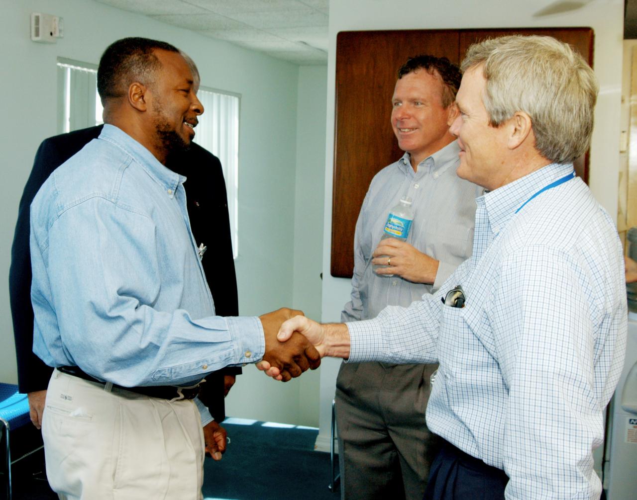
KENNEDY SPACE CENTER, FLA. - At the Beach House, Deputy Director Woodrow Whitlow Jr. (left) greets Bruce Melnick (right), vice president for Boeing Florida Operations at KSC. In the background is Congressman Tom Feeney. During January and February, Congressman Feeney traveled the entire coastline of Florida’s 24th District, and concluded his walks March 1 in Brevard County. On the walks, he met with constituents and community leaders to discuss legislative issues that will be addressed by the 108th Congress.
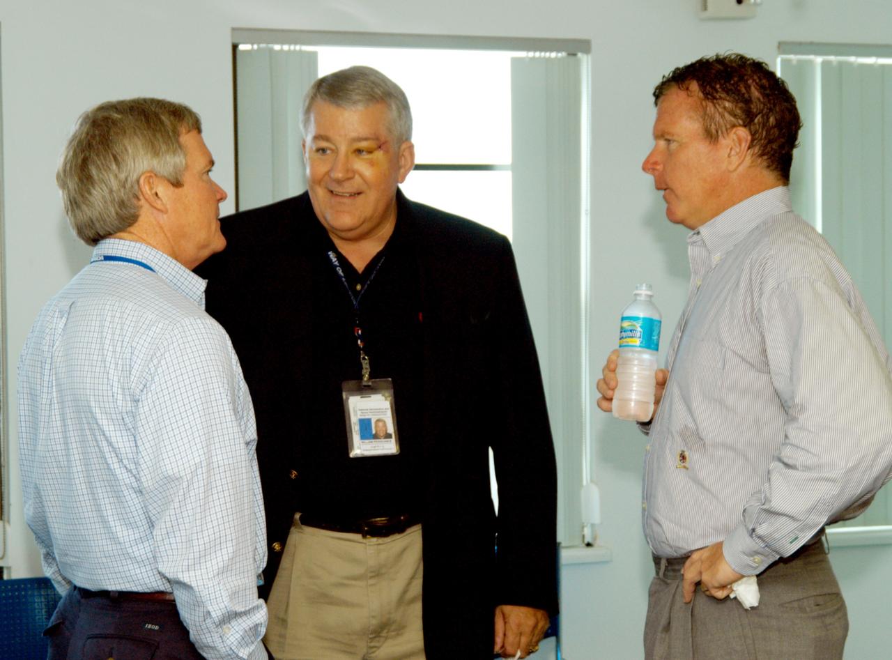
KENNEDY SPACE CENTER, FLA. - At the Beach House, Congressman Tom Feeney (right) talks with Bruce Melnick (left), vice president for Boeing Florida Operations at KSC, and Bill Pickavance, vice president, associate program manager of Florida Operations, United Space Alliance. During January and February, Congressman Feeney traveled the entire coastline of Florida’s 24th District, and concluded his walks March 1 in Brevard County. On his walks, he met with constituents and community leaders to discuss legislative issues that will be addressed by the 108th Congress.
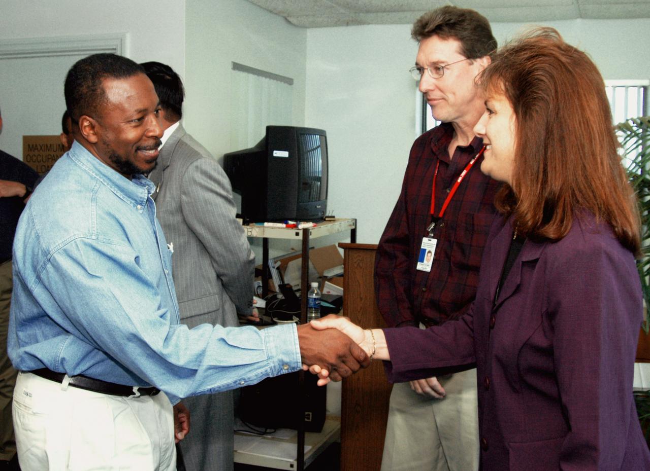
KENNEDY SPACE CENTER, FLA. - At the Beach House, Deputy Director Woodrow Whitlow Jr. greets Ellen Feeney, wife of Congressman Tom Feeney. Between them is Stan Starr, with Dynamac Corp. During January and February, Congressman Feeney traveled the entire coastline of Florida’s 24th District, and concluded his walks March 1 in Brevard County. On his walks, he met with constituents and community leaders to discuss legislative issues that will be addressed by the 108th Congress.

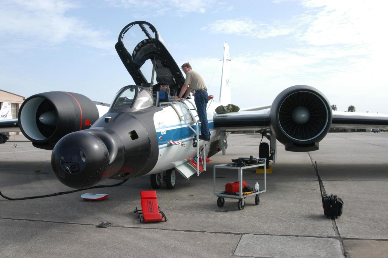
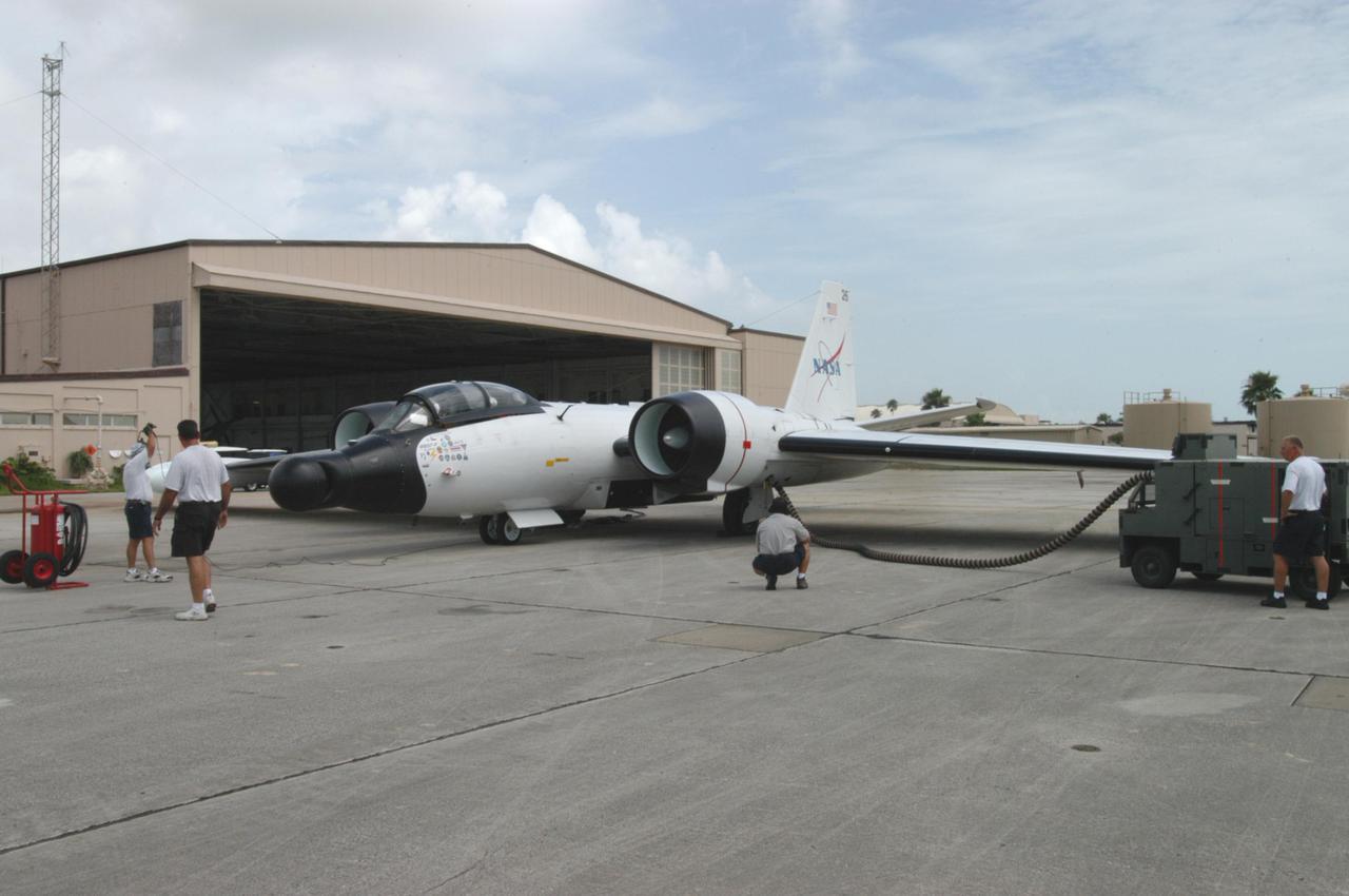
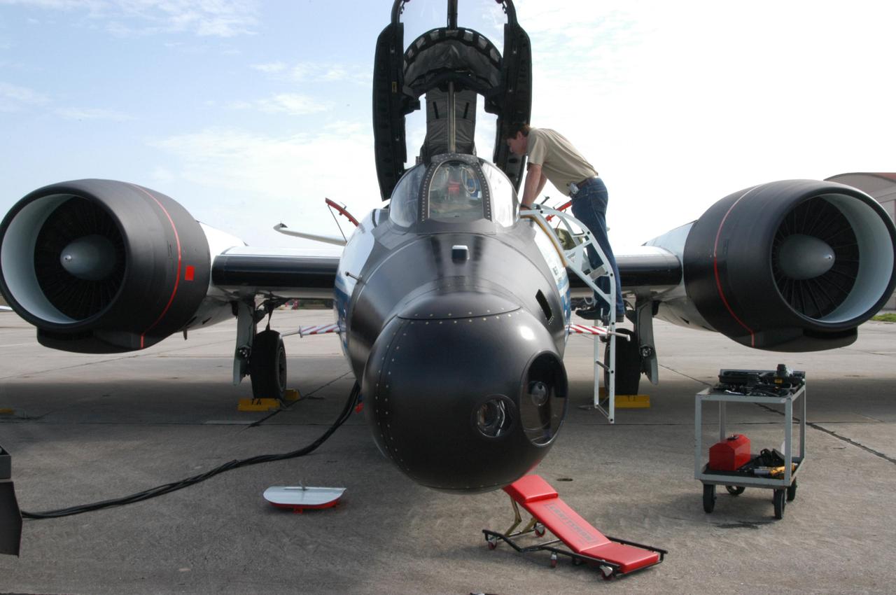
KENNEDY SPACE CENTER, FLA. - At Patrick Air Force Base in Cocoa Beach Beach, Fla., workers prepare the WB-57F aircraft that will take photos of Space Shuttle Discovery during its launch on Return to Flight mission STS-114. NASA approved the development and implementation of the aircraft-based imaging system, known as the WB-57 Ascent Video Experiment (WAVE). The WAVE provides both ascent and entry imagery and enables better observation of the Shuttle on days of heavier cloud cover and areas obscured from ground cameras by the launch exhaust plume. WAVE comprises a 32-inch-ball turret system mounted on the nose of two WB-57 aircraft. The turret houses an optical bench, providing installation of both HDTV and infrared cameras. Optics consist of an 11-inch-diameter, 4.2 meter fixed-focal-length lens. The system can be operated in both auto track and manual modes.
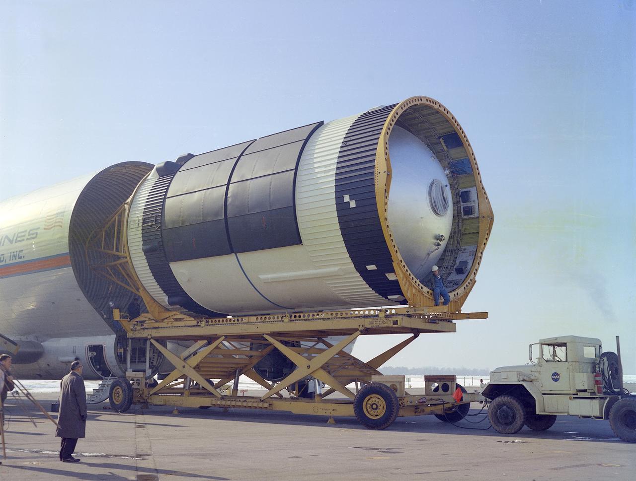
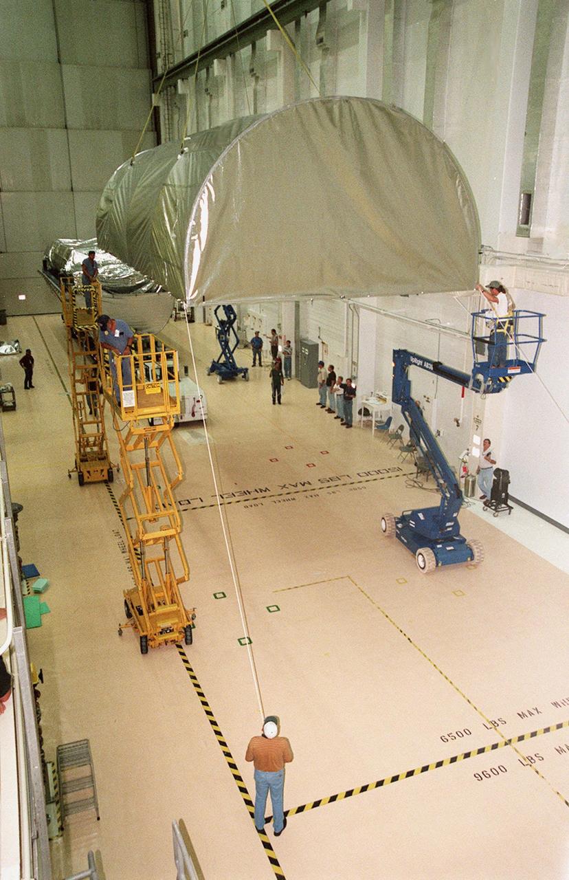
This photograph was taken at the Redstone airfield, Huntsville, Alabama, during the unloading of the Saturn V S-IVB stage that housed the Orbital Workshop (OWS) from the Super Guppy, the NASA plane that was specially built to carry oversized cargo. The OWS measured 22 feet (6.7 m) in diameter, and 48 feet (14.6 m) in length. The Saturn V S-IVB stage was modified at the McDornell Douglas facility at Huntington Beach, California, for a new role, which was to house the OWS. In addition to the test articles, engineering mockups, and flight equipment, both McDonnell Douglas and Martin Marietta built 0-G trainers, neutral buoyancy trainers, and high-fidelity mockups for the 1-G trainer to be used in the KC-135 aircraft. The Marshall Space Flight Center had program management responsibility for the development of Skylab hardware and experiments.

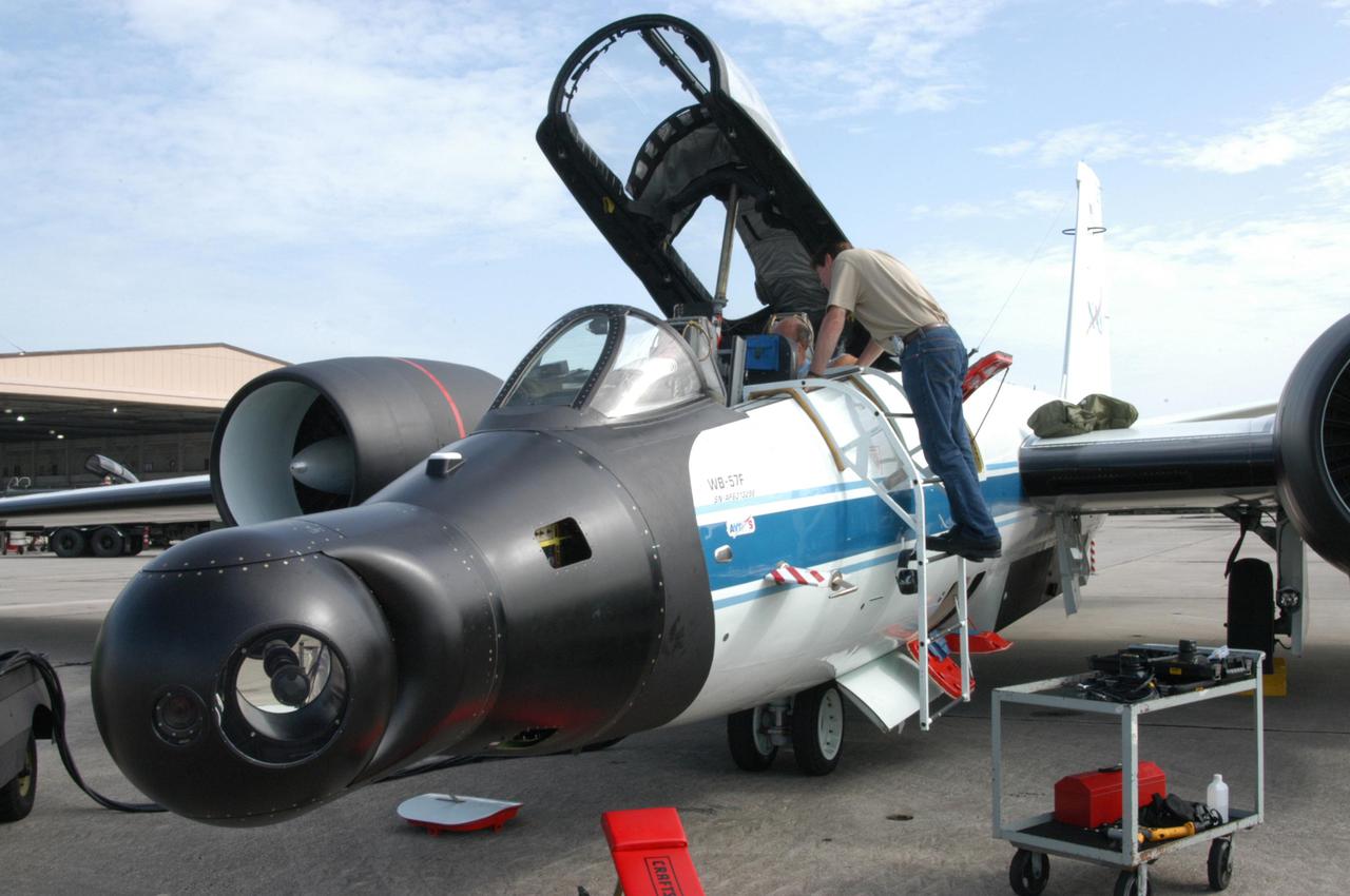
KENNEDY SPACE CENTER, FLA. - This view shows the 32-inch-ball turret system mounted on the nose of a WB-57 aircraft at Patrick Air Force Base in Cocoa Beach, Fla. It houses an optical bench, providing installation of both HDTV and infrared cameras as part of the NASA-approved WB-57 Ascent Video Experiment (WAVE). Flown during launch of a Space Shuttle, the WAVE provides both ascent and entry imagery and enables better observation of the Shuttle on days of heavier cloud cover and areas obscured from ground cameras by the launch exhaust plume. The WB-57 is being prepared for launch of Space Shuttle Discovery on Return to Flight mission STS-114.

KENNEDY SPACE CENTER, FLA. - At Patrick Air Force Base in Cocoa Beach, Fla., the WB-57F aircraft takes off on a test flight. The aircraft will take photos of Space Shuttle Discovery during its launch on Return to Flight mission STS-114. NASA approved the development and implementation of the aircraft-based imaging system, known as the WB-57 Ascent Video Experiment (WAVE). The WAVE provides both ascent and entry imagery and enables better observation of the Shuttle on days of heavier cloud cover and areas obscured from ground cameras by the launch exhaust plume. WAVE comprises a 32-inch-ball turret system mounted on the nose of two WB-57 aircraft. The turret houses an optical bench, providing installation of both HDTV and infrared cameras. Optics consist of an 11-inch-diameter, 4.2 meter fixed-focal-length lens. The system can be operated in both auto track and manual modes.

KENNEDY SPACE CENTER, FLA. - At Patrick Air Force Base in Cocoa Beach, Fla., the WB-57F aircraft taxis on the airfield before its test flight. The aircraft will take photos of Space Shuttle Discovery during its launch on Return to Flight mission STS-114. NASA approved the development and implementation of the aircraft-based imaging system, known as the WB-57 Ascent Video Experiment (WAVE). The WAVE provides both ascent and entry imagery and enables better observation of the Shuttle on days of heavier cloud cover and areas obscured from ground cameras by the launch exhaust plume. WAVE comprises a 32-inch-ball turret system mounted on the nose of two WB-57 aircraft. The turret houses an optical bench, providing installation of both HDTV and infrared cameras. Optics consist of an 11-inch-diameter, 4.2 meter fixed-focal-length lens. The system can be operated in both auto track and manual modes.
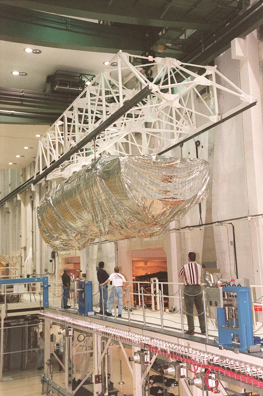
KENNEDY SPACE CENTER, FLA. -- Inside the Operations and Checkout Building, a strongback lifts the S1 truss from the Guppy cargo carrier that protected it during flight and transfer. Manufactured by the Boeing Co. in Huntington Beach, Calif., this component of the International Space Station is the first starboard (right-side) truss segment, whose main job is providing structural support for the orbiting research facility's radiator panels that cool the Space Station's complex power system. The S1 truss segment also will house communications systems, external experiment positions and other subsystems. Primarily constructed of aluminum, the truss segment is 45 feet long, 15 feet wide and 6 feet tall. When fully outfitted, it will weigh 31,137 pounds. The truss is slated for flight in 2001
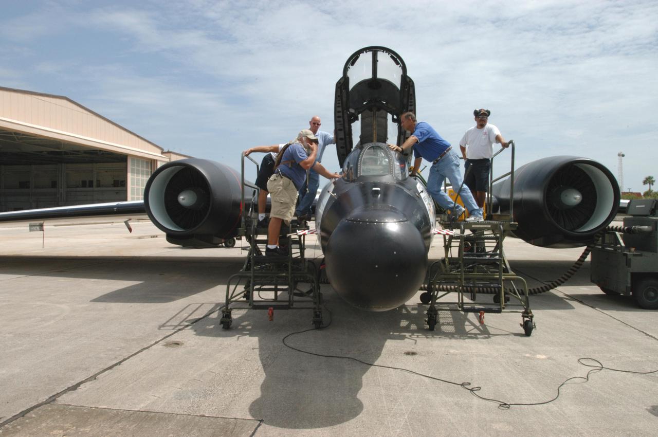
KENNEDY SPACE CENTER, FLA. - At Patrick Air Force Base in Cocoa Beach, Fla., workers prepare the WB-57F aircraft that will take photos of Space Shuttle Discovery during its launch on Return to Flight mission STS-114. NASA approved the development and implementation of the aircraft-based imaging system, known as the WB-57 Ascent Video Experiment (WAVE). The WAVE provides both ascent and entry imagery and enables better observation of the Shuttle on days of heavier cloud cover and areas obscured from ground cameras by the launch exhaust plume. WAVE comprises a 32-inch-ball turret system mounted on the nose of two WB-57 aircraft. The turret houses an optical bench, providing installation of both HDTV and infrared cameras. Optics consist of an 11-inch-diameter, 4.2 meter fixed-focal-length lens. The system can be operated in both auto track and manual modes.
KENNEDY SPACE CENTER, FLA. -- Inside the Operations and Checkout Building, the top of the Guppy cargo carrier is lifted off the S1 truss (background). Manufactured by the Boeing Co. in Huntington Beach, Calif., this component of the International Space Station is the first starboard (right-side) truss segment, whose main job is providing structural support for the orbiting research facility's radiator panels that cool the Space Station's complex power system. The S1 truss segment also will house communications systems, external experiment positions and other subsystems. Primarily constructed of aluminum, the truss segment is 45 feet long, 15 feet wide and 6 feet tall. When fully outfitted, it will weigh 31,137 pounds. The truss is slated for flight in 2001

KENNEDY SPACE CENTER, FLA. -- A KSC transporter moves the Guppy cargo carrier encasing the S1 truss into the Operations and Checkout Building. Manufactured by the Boeing Co. in Huntington Beach, Calif., this component of the International Space Station is the first starboard (right-side) truss segment, whose main job is providing structural support for the orbiting research facility's radiator panels that cool the Space Station's complex power system. The S1 truss segment also will house communications systems, external experiment positions and other subsystems. Primarily constructed of aluminum, the truss segment is 45 feet long, 15 feet wide and 6 feet tall. When fully outfitted, it will weigh 31,137 pounds. The truss is slated for flight in 2001
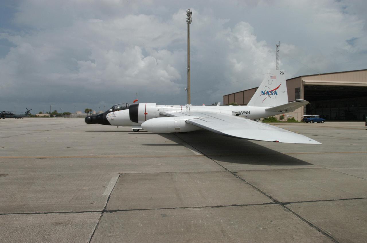
KENNEDY SPACE CENTER, FLA. - At Patrick Air Force Base in Cocoa Beach, Fla., the WB-57F aircraft is ready for a test flight. The aircraft will take photos of Space Shuttle Discovery during its launch on Return to Flight mission STS-114. NASA approved the development and implementation of the aircraft-based imaging system, known as the WB-57 Ascent Video Experiment (WAVE). The WAVE provides both ascent and entry imagery and enables better observation of the Shuttle on days of heavier cloud cover and areas obscured from ground cameras by the launch exhaust plume. WAVE comprises a 32-inch-ball turret system mounted on the nose of two WB-57 aircraft. The turret houses an optical bench, providing installation of both HDTV and infrared cameras. Optics consist of an 11-inch-diameter, 4.2 meter fixed-focal-length lens. The system can be operated in both auto track and manual modes.
KENNEDY SPACE CENTER, FLA. - At Patrick Air Force Base in Cocoa Beach, Fla., workers prepare the WB-57F aircraft that will take photos of Space Shuttle Discovery during its launch on Return to Flight mission STS-114. NASA approved the development and implementation of the aircraft-based imaging system, known as the WB-57 Ascent Video Experiment (WAVE). The WAVE provides both ascent and entry imagery and enables better observation of the Shuttle on days of heavier cloud cover and areas obscured from ground cameras by the launch exhaust plume. WAVE comprises a 32-inch-ball turret system mounted on the nose of two WB-57 aircraft. The turret houses an optical bench, providing installation of both HDTV and infrared cameras. Optics consist of an 11-inch-diameter, 4.2 meter fixed-focal-length lens. The system can be operated in both auto track and manual modes.
KENNEDY SPACE CENTER, FLA. -- Inside the Operations and Checkout Building, the S1 truss, a segment of the International Space Station, is lowered toward workstand number three. Manufactured by the Boeing Co. in Huntington Beach, Calif., this component of the International Space Station is the first starboard (right-side) truss segment, whose main job is providing structural support for the orbiting research facility's radiator panels that cool the Space Station's complex power system. The S1 truss segment also will house communications systems, external experiment positions and other subsystems. Primarily constructed of aluminum, the truss segment is 45 feet long, 15 feet wide and 6 feet tall. When fully outfitted, it will weigh 31,137 pounds. The truss is slated for flight in 2001
KENNEDY SPACE CENTER, FLA. - At Patrick Air Force Base in Cocoa Beach, Fla., a WB-57F aircraft is being prepared for a practice flight. The aircraft will take photos of Space Shuttle Discovery during its launch on Return to Flight mission STS-114. NASA approved the development and implementation of the aircraft-based imaging system, known as the WB-57 Ascent Video Experiment (WAVE). The WAVE provides both ascent and entry imagery and enables better observation of the Shuttle on days of heavier cloud cover and areas obscured from ground cameras by the launch exhaust plume. WAVE comprises a 32-inch-ball turret system mounted on the nose of two WB-57 aircraft. The turret houses an optical bench, providing installation of both HDTV and infrared cameras. Optics consist of an 11-inch-diameter, 4.2 meter fixed-focal-length lens. The system can be operated in both auto track and manual modes.
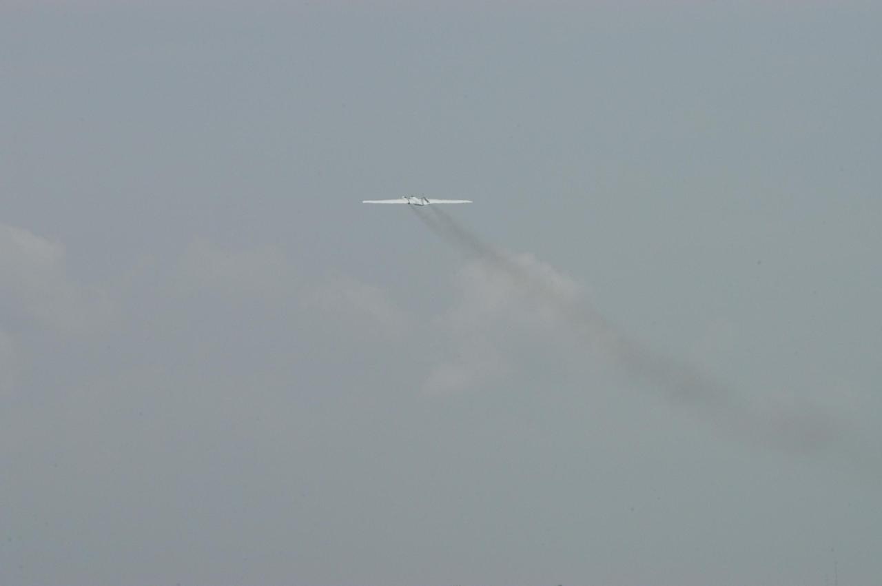
KENNEDY SPACE CENTER, FLA. - Over Patrick Air Force Base in Cocoa Beach, Fla., the WB-57F aircraft is airborne for a test flight. The aircraft will take photos of Space Shuttle Discovery during its launch on Return to Flight mission STS-114. NASA approved the development and implementation of the aircraft-based imaging system, known as the WB-57 Ascent Video Experiment (WAVE). The WAVE provides both ascent and entry imagery and enables better observation of the Shuttle on days of heavier cloud cover and areas obscured from ground cameras by the launch exhaust plume. WAVE comprises a 32-inch-ball turret system mounted on the nose of two WB-57 aircraft. The turret houses an optical bench, providing installation of both HDTV and infrared cameras. Optics consist of an 11-inch-diameter, 4.2 meter fixed-focal-length lens. The system can be operated in both auto track and manual modes.
KENNEDY SPACE CENTER, FLA. -- Inside the Operations and Checkout Building, the S1 truss, a segment of the International Space Station, is moved toward workstand number three. Manufactured by the Boeing Co. in Huntington Beach, Calif., this component of the International Space Station is the first starboard (right-side) truss segment, whose main job is providing structural support for the orbiting research facility's radiator panels that cool the Space Station's complex power system. The S1 truss segment also will house communications systems, external experiment positions and other subsystems. Primarily constructed of aluminum, the truss segment is 45 feet long, 15 feet wide and 6 feet tall. When fully outfitted, it will weigh 31,137 pounds. The truss is slated for flight in 2001
KENNEDY SPACE CENTER, FLA. - At Patrick Air Force Base in Cocoa Beach, Fla., workers prepare the WB-57F aircraft that will take photos of Space Shuttle Discovery during its launch on Return to Flight mission STS-114. NASA approved the development and implementation of the aircraft-based imaging system, known as the WB-57 Ascent Video Experiment (WAVE). The WAVE provides both ascent and entry imagery and enables better observation of the Shuttle on days of heavier cloud cover and areas obscured from ground cameras by the launch exhaust plume. WAVE comprises a 32-inch-ball turret system mounted on the nose of two WB-57 aircraft. The turret houses an optical bench, providing installation of both HDTV and infrared cameras. Optics consist of an 11-inch-diameter, 4.2 meter fixed-focal-length lens. The system can be operated in both auto track and manual modes.
KENNEDY SPACE CENTER, FLA. -- Inside the Operations and Checkout Building, a strongback is lowered toward the S1 truss below it in order to lift the truss from the Guppy cargo carrier that protected it during flight and transfer. Manufactured by the Boeing Co. in Huntington Beach, Calif., this component of the International Space Station is the first starboard (right-side) truss segment, whose main job is providing structural support for the orbiting research facility's radiator panels that cool the Space Station's complex power system. The S1 truss segment also will house communications systems, external experiment positions and other subsystems. Primarily constructed of aluminum, the truss segment is 45 feet long, 15 feet wide and 6 feet tall. When fully outfitted, it will weigh 31,137 pounds. The truss is slated for flight in 2001
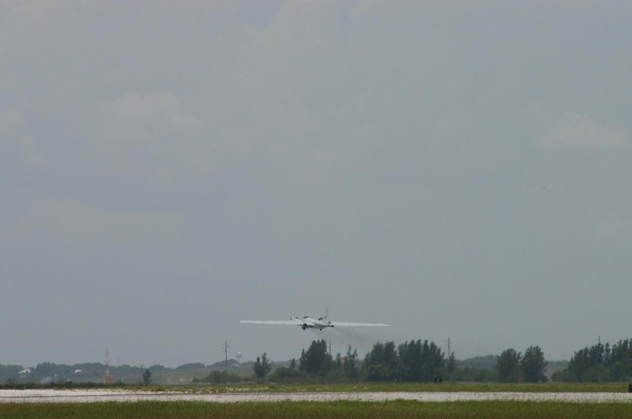
KENNEDY SPACE CENTER, FLA. - At Patrick Air Force Base in Cocoa Beach, Fla., the WB-57F aircraft takes off on a test flight. The aircraft will take photos of Space Shuttle Discovery during its launch on Return to Flight mission STS-114. NASA approved the development and implementation of the aircraft-based imaging system, known as the WB-57 Ascent Video Experiment (WAVE). The WAVE provides both ascent and entry imagery and enables better observation of the Shuttle on days of heavier cloud cover and areas obscured from ground cameras by the launch exhaust plume. WAVE comprises a 32-inch-ball turret system mounted on the nose of two WB-57 aircraft. The turret houses an optical bench, providing installation of both HDTV and infrared cameras. Optics consist of an 11-inch-diameter, 4.2 meter fixed-focal-length lens. The system can be operated in both auto track and manual modes.
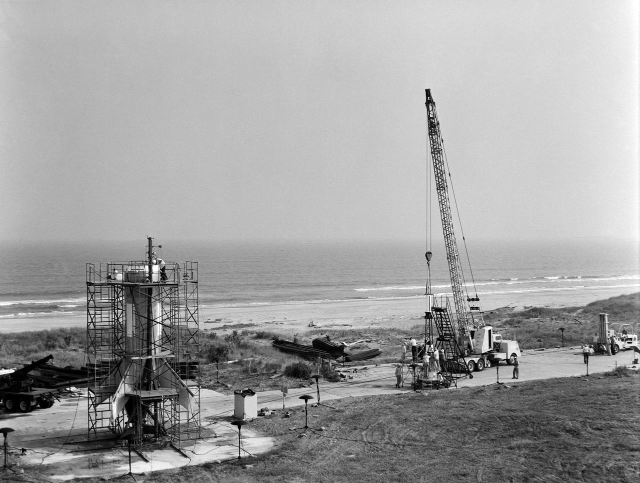
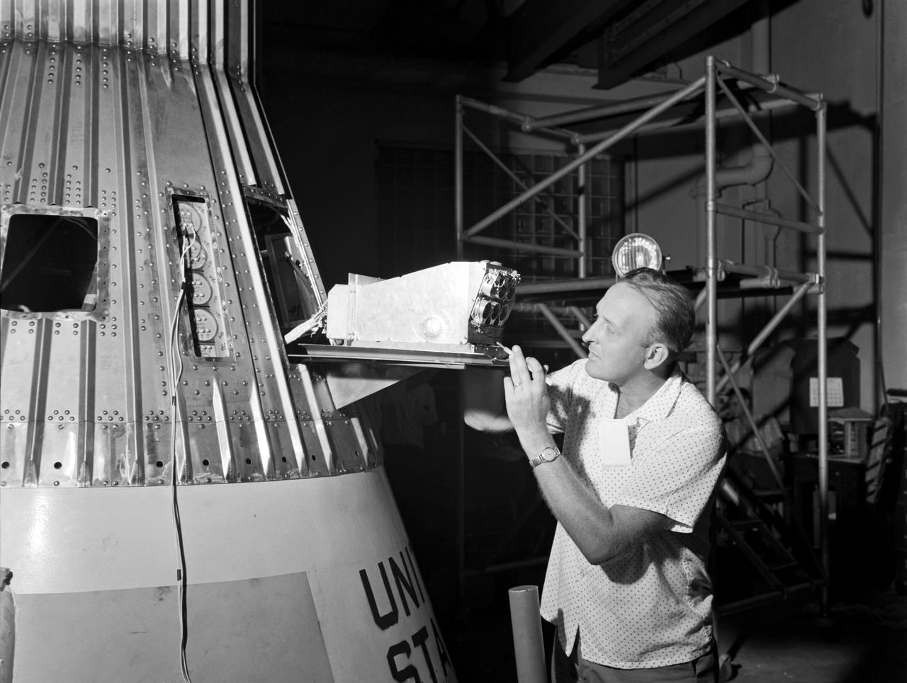
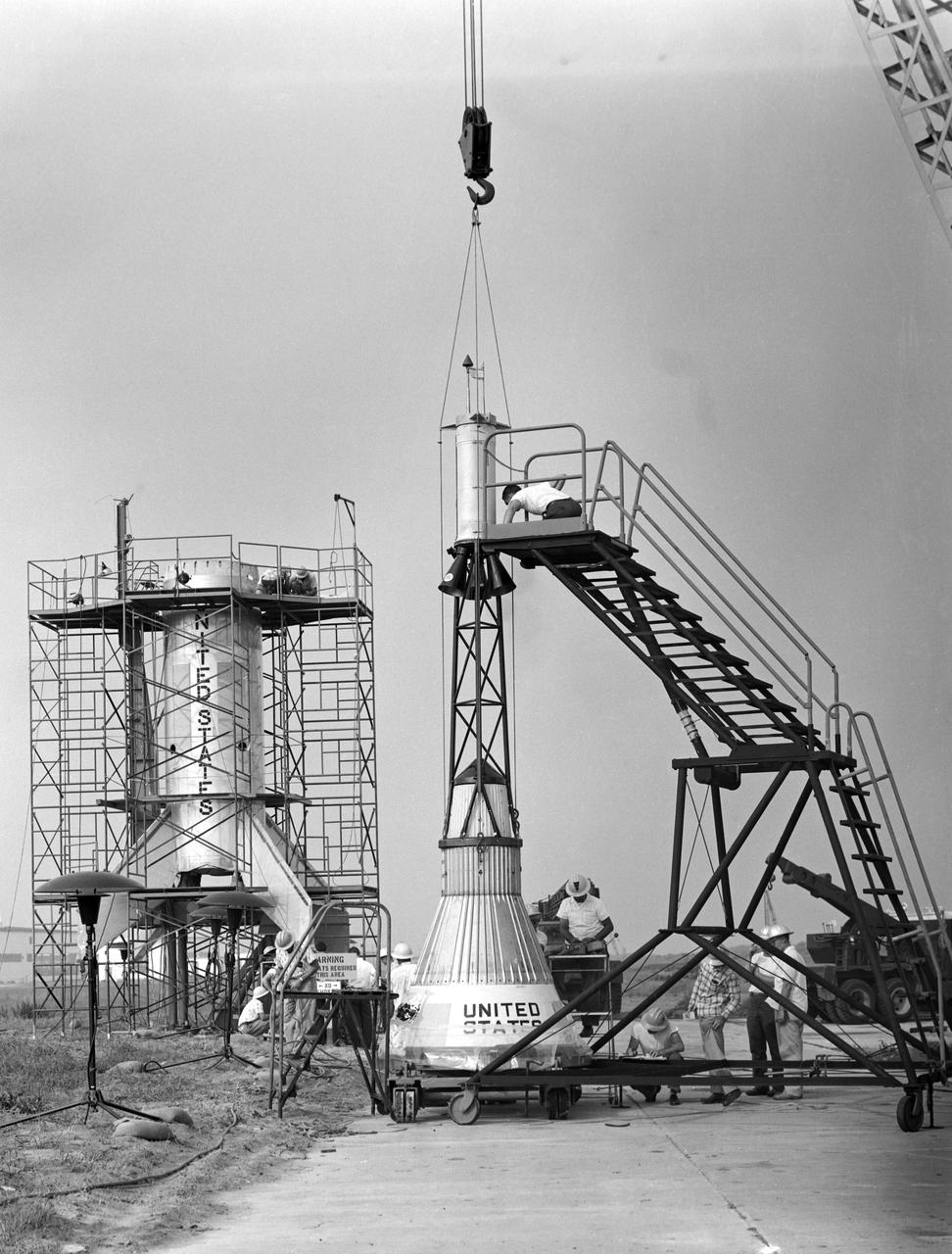
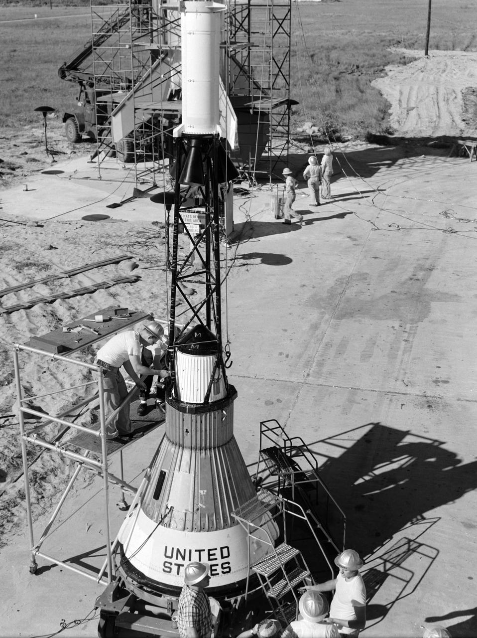
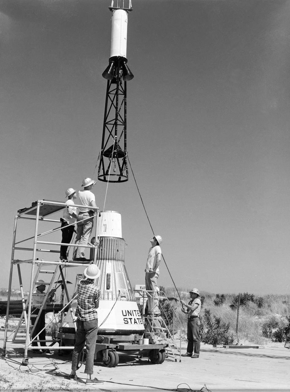
Technicians attach the escape tower to the Mercury capsule prior to assembly with Little Joe launcher, August 20, 1959. Joseph Shortal describe this as follows (vol. 3., p. 33): The escape tower and rocket motors were taken from the Mercury capsule production. The tower is shown being attached to the capsule.... The escape rocket was a Grand Central 1-KS-52000 motor with three canted nozzles. The tower-jettison motor was an Atlantic Research Corp. 1.4-KS-785 motor. This was the same design tested in a beach abort test...and had the offset thrust line as used in the beach abort test to insure that the capsule would get away from the booster in an emergency. The escape system weighed 1,015 pounds, including 236 pounds of ballast for stability. The Little Joe booster was assembled at Wallops on its special launcher in a vertical attitude. It is shown in the on the left with the work platform in place. The launcher was located on a special concrete slab in Launching Area 1. The capsule was lowered onto the booster by crane.... After the assembly was completed, the scaffolding was disassembled and the launcher pitched over to its normal launch angle of 80 degrees.... Little Joe had a diameter of 80 inches and an overall length, including the capsule and escape tower of 48 feet. The total weight at launch was about 43,000 pounds. The overall span of the stabilizing fins was 21.3 feet. Although in comparison with the overall Mercury Project, Little Joe was a simple undertaking, the fact that an attempt was made to condense a normal two-year project into a 6-month one with in house labor turned it into a major undertaking for Langley. -- Published in Joseph A. Shortal, History of Wallops Station: Origins and Activities Through 1949, (Wallops Island, VA: National Aeronautics and Space Administration, Wallops Station, nd), Comment Edition.
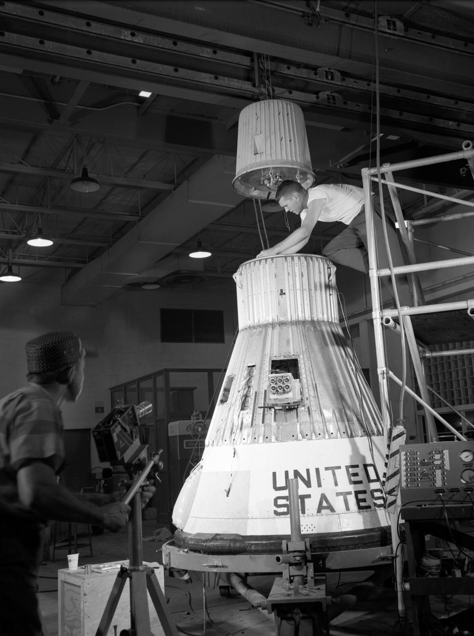
Technicians adjust the rocket motor during the attachment of the escape tower to the Mercury capsule prior to assembly with Little Joe launcher, August 20, 1959. Joseph Shortal wrote (vol. 3., p. 33): The escape tower and rocket motors were taken from the Mercury capsule production. The tower is shown being attached to the capsule.... The escape rocket was a Grand Central 1-KS-52000 motor with three canted nozzles. The tower-jettison motor was an Atlantic Research Corp. 1.4-KS-785 motor. This was the same design tested in a beach abort test...and had the offset thrust line as used in the beach abort test to insure that the capsule would get away from the booster in an emergency. The escape system weighed 1,015 pounds, including 236 pounds of ballast for stability. The Little Joe booster was assembled at Wallops on its special launcher in a vertical attitude. It is shown in the on the left with the work platform in place. The launcher was located on a special concrete slab in Launching Area 1. The capsule was lowered onto the booster by crane.... After the assembly was completed, the scaffolding was disassembled and the launcher pitched over to its normal launch angle of 80 degrees.... Little Joe had a diameter of 80 inches and an overall length, including the capsule and escape tower of 48 feet. The total weight at launch was about 43,000 pounds. The overall span of the stabilizing fins was 21.3 feet. Although in comparison with the overall Mercury Project, Little Joe was a simple undertaking, the fact that an attempt was made to condense a normal two-year project into a 6-month one with in house labor turned it into a major undertaking for Langley. -- Published in Joseph A. Shortal, History of Wallops Station: Origins and Activities Through 1949, (Wallops Island, VA: National Aeronautics and Space Administration, Wallops Station, nd), Comment Edition.
Technicians adjust the rocket motor during the attachment of the escape tower to the Mercury capsule prior to assembly with Little Joe launcher, August 20, 1959. Joseph Shortal wrote (vol. 3., p. 33): The escape tower and rocket motors were taken from the Mercury capsule production. The tower is shown being attached to the capsule.... The escape rocket was a Grand Central 1-KS-52000 motor with three canted nozzles. The tower-jettison motor was an Atlantic Research Corp. 1.4-KS-785 motor. This was the same design tested in a beach abort test...and had the offset thrust line as used in the beach abort test to insure that the capsule would get away from the booster in an emergency. The escape system weighed 1,015 pounds, including 236 pounds of ballast for stability. The Little Joe booster was assembled at Wallops on its special launcher in a vertical attitude. It is shown in the on the left with the work platform in place. The launcher was located on a special concrete slab in Launching Area 1. The capsule was lowered onto the booster by crane.... After the assembly was completed, the scaffolding was disassembled and the launcher pitched over to its normal launch angle of 80 degrees.... Little Joe had a diameter of 80 inches and an overall length, including the capsule and escape tower of 48 feet. The total weight at launch was about 43,000 pounds. The overall span of the stabilizing fins was 21.3 feet. Although in comparison with the overall Mercury Project, Little Joe was a simple undertaking, the fact that an attempt was made to condense a normal two-year project into a 6-month one with in house labor turned it into a major undertaking for Langley. -- Published in Joseph A. Shortal, History of Wallops Station: Origins and Activities Through 1949, (Wallops Island, VA: National Aeronautics and Space Administration, Wallops Station, nd), Comment Edition.
Technicians adjust the rocket motor during the attachment of the escape tower to the Mercury capsule prior to assembly with Little Joe launcher, August 20, 1959. Joseph Shortal wrote (vol. 3., p. 33): The escape tower and rocket motors were taken from the Mercury capsule production. The tower is shown being attached to the capsule.... The escape rocket was a Grand Central 1-KS-52000 motor with three canted nozzles. The tower-jettison motor was an Atlantic Research Corp. 1.4-KS-785 motor. This was the same design tested in a beach abort test...and had the offset thrust line as used in the beach abort test to insure that the capsule would get away from the booster in an emergency. The escape system weighed 1,015 pounds, including 236 pounds of ballast for stability. The Little Joe booster was assembled at Wallops on its special launcher in a vertical attitude. It is shown in the on the left with the work platform in place. The launcher was located on a special concrete slab in Launching Area 1. The capsule was lowered onto the booster by crane.... After the assembly was completed, the scaffolding was disassembled and the launcher pitched over to its normal launch angle of 80 degrees.... Little Joe had a diameter of 80 inches and an overall length, including the capsule and escape tower of 48 feet. The total weight at launch was about 43,000 pounds. The overall span of the stabilizing fins was 21.3 feet. Although in comparison with the overall Mercury Project, Little Joe was a simple undertaking, the fact that an attempt was made to condense a normal two-year project into a 6-month one with in house labor turned it into a major undertaking for Langley. -- Published in Joseph A. Shortal, History of Wallops Station: Origins and Activities Through 1949, (Wallops Island, VA: National Aeronautics and Space Administration, Wallops Station, nd), Comment Edition.
Technicians attach the escape tower to the Mercury capsule prior to assembly with Little Joe launcher, August 20, 1959. Joseph Shortal describe this as follows (vol. 3., p. 33): The escape tower and rocket motors were taken from the Mercury capsule production. The tower is shown being attached to the capsule.... The escape rocket was a Grand Central 1-KS-52000 motor with three canted nozzles. The tower-jettison motor was an Atlantic Research Corp. 1.4-KS-785 motor. This was the same design tested in a beach abort test...and had the offset thrust line as used in the beach abort test to insure that the capsule would get away from the booster in an emergency. The escape system weighed 1,015 pounds, including 236 pounds of ballast for stability. The Little Joe booster was assembled at Wallops on its special launcher in a vertical attitude. It is shown in the on the left with the work platform in place. The launcher was located on a special concrete slab in Launching Area 1. The capsule was lowered onto the booster by crane.... After the assembly was completed, the scaffolding was disassembled and the launcher pitched over to its normal launch angle of 80 degrees.... Little Joe had a diameter of 80 inches and an overall length, including the capsule and escape tower of 48 feet. The total weight at launch was about 43,000 pounds. The overall span of the stabilizing fins was 21.3 feet. Although in comparison with the overall Mercury Project, Little Joe was a simple undertaking, the fact that an attempt was made to condense a normal two-year project into a 6-month one with in house labor turned it into a major undertaking for Langley. -- Published in Joseph A. Shortal, History of Wallops Station: Origins and Activities Through 1949, (Wallops Island, VA: National Aeronautics and Space Administration, Wallops Station, nd), Comment Edition.

Technicians adjust the rocket motor during the attachment of the escape tower to the Mercury capsule prior to assembly with Little Joe launcher, August 20, 1959. Joseph Shortal wrote (vol. 3., p. 33): The escape tower and rocket motors were taken from the Mercury capsule production. The tower is shown being attached to the capsule.... The escape rocket was a Grand Central 1-KS-52000 motor with three canted nozzles. The tower-jettison motor was an Atlantic Research Corp. 1.4-KS-785 motor. This was the same design tested in a beach abort test...and had the offset thrust line as used in the beach abort test to insure that the capsule would get away from the booster in an emergency. The escape system weighed 1,015 pounds, including 236 pounds of ballast for stability. The Little Joe booster was assembled at Wallops on its special launcher in a vertical attitude. It is shown in the on the left with the work platform in place. The launcher was located on a special concrete slab in Launching Area 1. The capsule was lowered onto the booster by crane.... After the assembly was completed, the scaffolding was disassembled and the launcher pitched over to its normal launch angle of 80 degrees.... Little Joe had a diameter of 80 inches and an overall length, including the capsule and escape tower of 48 feet. The total weight at launch was about 43,000 pounds. The overall span of the stabilizing fins was 21.3 feet. Although in comparison with the overall Mercury Project, Little Joe was a simple undertaking, the fact that an attempt was made to condense a normal two-year project into a 6-month one with in house labor turned it into a major undertaking for Langley. -- Published in Joseph A. Shortal, History of Wallops Station: Origins and Activities Through 1949, (Wallops Island, VA: National Aeronautics and Space Administration, Wallops Station, nd), Comment Edition.
Technicians adjust the rocket motor during the attachment of the escape tower to the Mercury capsule prior to assembly with Little Joe launcher, August 20, 1959. Joseph Shortal wrote (vol. 3., p. 33): The escape tower and rocket motors were taken from the Mercury capsule production. The tower is shown being attached to the capsule.... The escape rocket was a Grand Central 1-KS-52000 motor with three canted nozzles. The tower-jettison motor was an Atlantic Research Corp. 1.4-KS-785 motor. This was the same design tested in a beach abort test...and had the offset thrust line as used in the beach abort test to insure that the capsule would get away from the booster in an emergency. The escape system weighed 1,015 pounds, including 236 pounds of ballast for stability. The Little Joe booster was assembled at Wallops on its special launcher in a vertical attitude. It is shown in the on the left with the work platform in place. The launcher was located on a special concrete slab in Launching Area 1. The capsule was lowered onto the booster by crane.... After the assembly was completed, the scaffolding was disassembled and the launcher pitched over to its normal launch angle of 80 degrees.... Little Joe had a diameter of 80 inches and an overall length, including the capsule and escape tower of 48 feet. The total weight at launch was about 43,000 pounds. The overall span of the stabilizing fins was 21.3 feet. Although in comparison with the overall Mercury Project, Little Joe was a simple undertaking, the fact that an attempt was made to condense a normal two-year project into a 6-month one with in house labor turned it into a major undertaking for Langley. -- Published in Joseph A. Shortal, History of Wallops Station: Origins and Activities Through 1949, (Wallops Island, VA: National Aeronautics and Space Administration, Wallops Station, nd), Comment Edition.
Technicians attach the escape tower to the Mercury capsule prior to assembly with Little Joe launcher, August 20, 1959. Joseph Shortal describe this as follows (vol. 3., p. 33): The escape tower and rocket motors were taken from the Mercury capsule production. The tower is shown being attached to the capsule.... The escape rocket was a Grand Central 1-KS-52000 motor with three canted nozzles. The tower-jettison motor was an Atlantic Research Corp. 1.4-KS-785 motor. This was the same design tested in a beach abort test...and had the offset thrust line as used in the beach abort test to insure that the capsule would get away from the booster in an emergency. The escape system weighed 1,015 pounds, including 236 pounds of ballast for stability. The Little Joe booster was assembled at Wallops on its special launcher in a vertical attitude. It is shown in the on the left with the work platform in place. The launcher was located on a special concrete slab in Launching Area 1. The capsule was lowered onto the booster by crane.... After the assembly was completed, the scaffolding was disassembled and the launcher pitched over to its normal launch angle of 80 degrees.... Little Joe had a diameter of 80 inches and an overall length, including the capsule and escape tower of 48 feet. The total weight at launch was about 43,000 pounds. The overall span of the stabilizing fins was 21.3 feet. Although in comparison with the overall Mercury Project, Little Joe was a simple undertaking, the fact that an attempt was made to condense a normal two-year project into a 6-month one with in house labor turned it into a major undertaking for Langley. -- Published in Joseph A. Shortal, History of Wallops Station: Origins and Activities Through 1949, (Wallops Island, VA: National Aeronautics and Space Administration, Wallops Station, nd), Comment Edition.
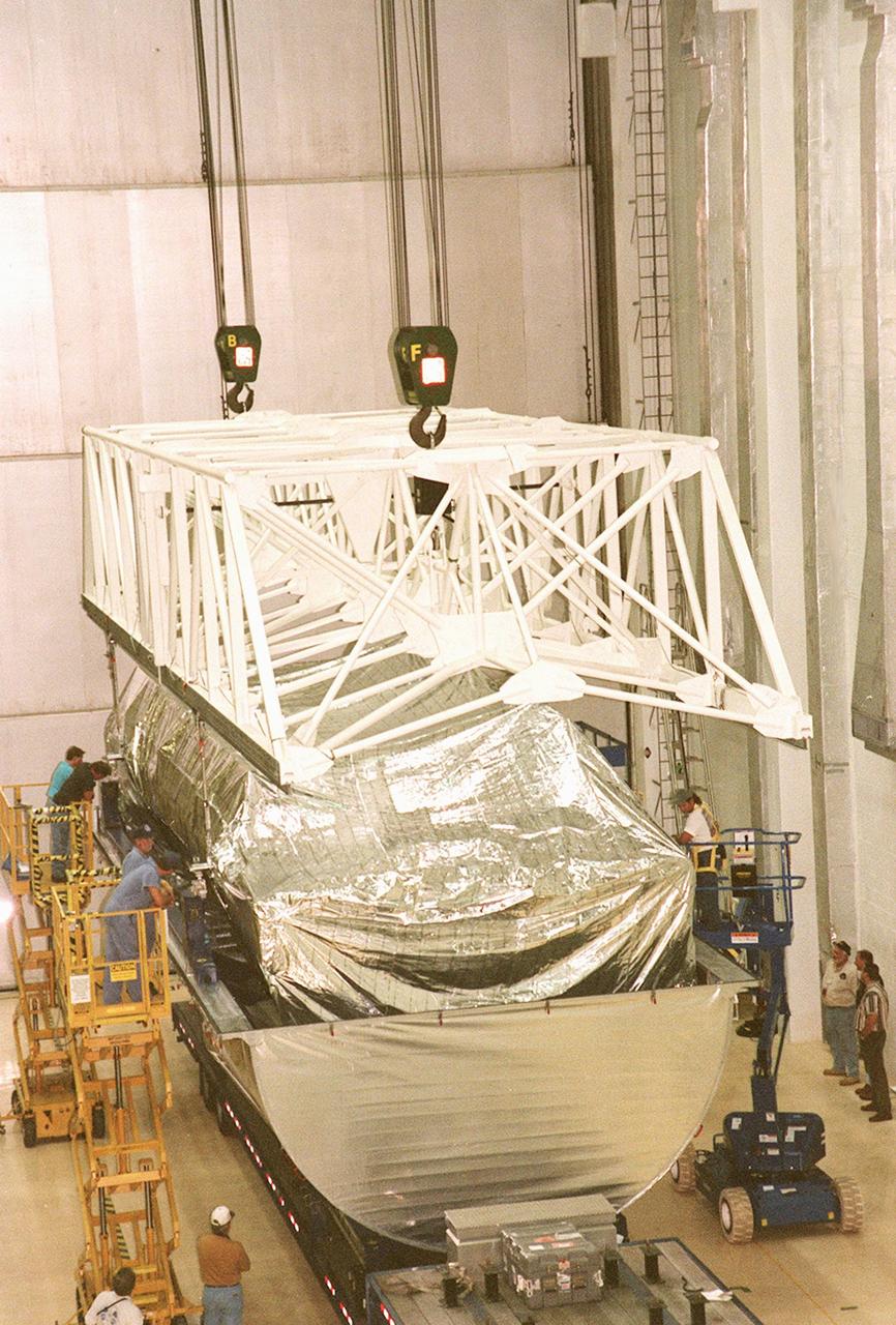
KENNEDY SPACE CENTER, FLA. -- Escort vehicles prepare to leave the Shuttle Landing Facility with the S1 truss (at right) on its trek to the Operations and Checkout Building. Manufactured by the Boeing Co. in Huntington Beach, Calif., this component of the ISS is the first starboard (right-side) truss segment, whose main job is providing structural support for the orbiting research facility's radiator panels that cool the Space Station's complex power system. The S1 truss segment also will house communications systems, external experiment positions and other subsystems. Primarily constructed of aluminum, the truss segment is 45 feet long, 15 feet wide and 6 feet tall. When fully outfitted, it will weigh 31,137 pounds. The truss is slated for flight in 2001. The truss arrived at KSC aboard NASA's Super Guppy, seen in the background. The aircraft is uniquely built with a 25-foot diameter fuselage designed to handle oversized loads and a "fold-away" nose that opens 110 degrees for cargo loading. A system of rails in the cargo compartment, used with either Guppy pallets or fixtures designed for specific cargo, makes cargo loading simple and efficient. Rollers mounted in the rails allow pallets or fixtures to be moved by an electric winch mounted beneath the cargo floor. Automatic hydraulic lock pins in each rail secure the pallet for flight
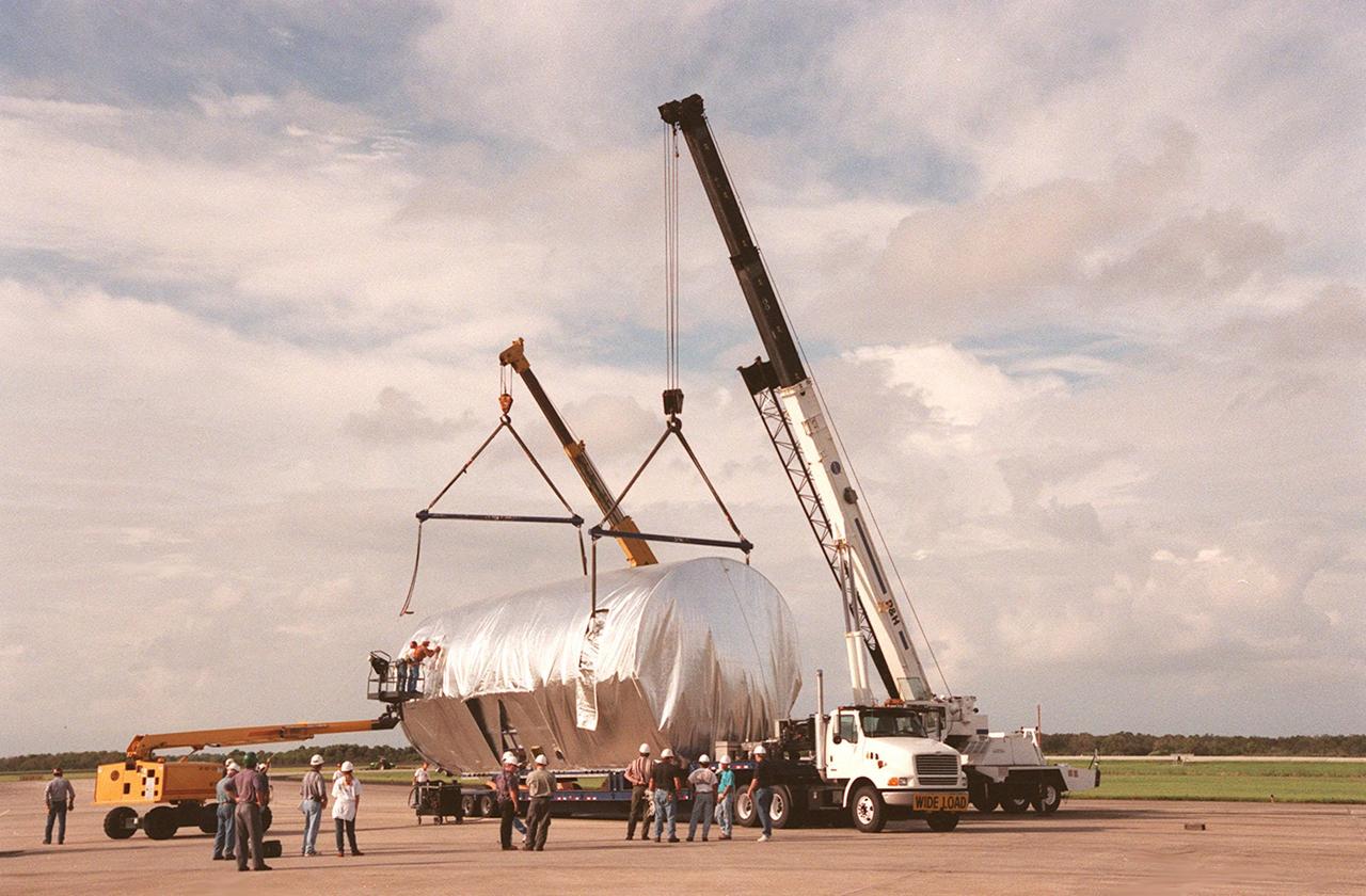
KENNEDY SPACE CENTER, FLA. -- At the Shuttle Landing Facility, workers attach cranes to the S1 truss, a segment of the International Space Station, to lift the truss to a payload transporter for its transfer to the Operations and Checkout Building. Manufactured by the Boeing Co. in Huntington Beach, Calif., this component of the ISS is the first starboard (right-side) truss segment, whose main job is providing structural support for the orbiting research facility's radiator panels that cool the Space Station's complex power system. The S1 truss segment also will house communications systems, external experiment positions and other subsystems. Primarily constructed of aluminum, the truss segment is 45 feet long, 15 feet wide and 6 feet tall. When fully outfitted, it will weigh 31,137 pounds. The truss is slated for flight in 2001. The truss arrived at KSC aboard NASA's Super Guppy, with a 25-foot diameter fuselage designed to handle oversized loads. Loading the Guppy is easy because of the unique "fold-away" nose of the aircraft that opens 110 degrees for cargo loading. A system of rails in the cargo compartment, used with either Guppy pallets or fixtures designed for specific cargo, makes cargo loading simple and efficient. Rollers mounted in the rails allow pallets or fixtures to be moved by an electric winch mounted beneath the cargo floor. Automatic hydraulic lock pins in each rail secure the pallet for flight
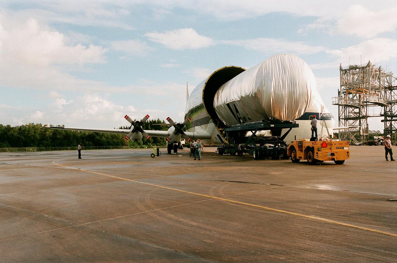
KENNEDY SPACE CENTER, FLA. -- At the Shuttle Landing Facility, the newly arrived S1 truss, a segment of the International Space Station (ISS), is offloaded from NASA's Super Guppy aircraft. Manufactured by the Boeing Co. in Huntington Beach, Calif., this component of the ISS is the first starboard (right-side) truss segment, whose main job is providing structural support for the orbiting research facility's radiator panels that cool the Space Station's complex power system. The S1 truss segment also will house communications systems, external experiment positions and other subsystems. Primarily constructed of aluminum, the truss segment is 45 feet long, 15 feet wide and 6 feet tall. When fully outfitted, it will weigh 31,137 pounds. The truss is slated for flight in 2001. The Super Guppy, with its 25-foot diameter fuselage designed to handle oversized loads, is well prepared to transport the truss and other ISS segments. Loading the Guppy is easy because of the unique "fold-away" nose of the aircraft that opens 110 degrees for cargo loading. A system of rails in the cargo compartment, used with either Guppy pallets or fixtures designed for specific cargo, makes cargo loading simple and efficient. Rollers mounted in the rails allow pallets or fixtures to be moved by an electric winch mounted beneath the cargo floor. Automatic hydraulic lock pins in each rail secure the pallet for flight. The truss is being transferred to the Operations and Checkout Building
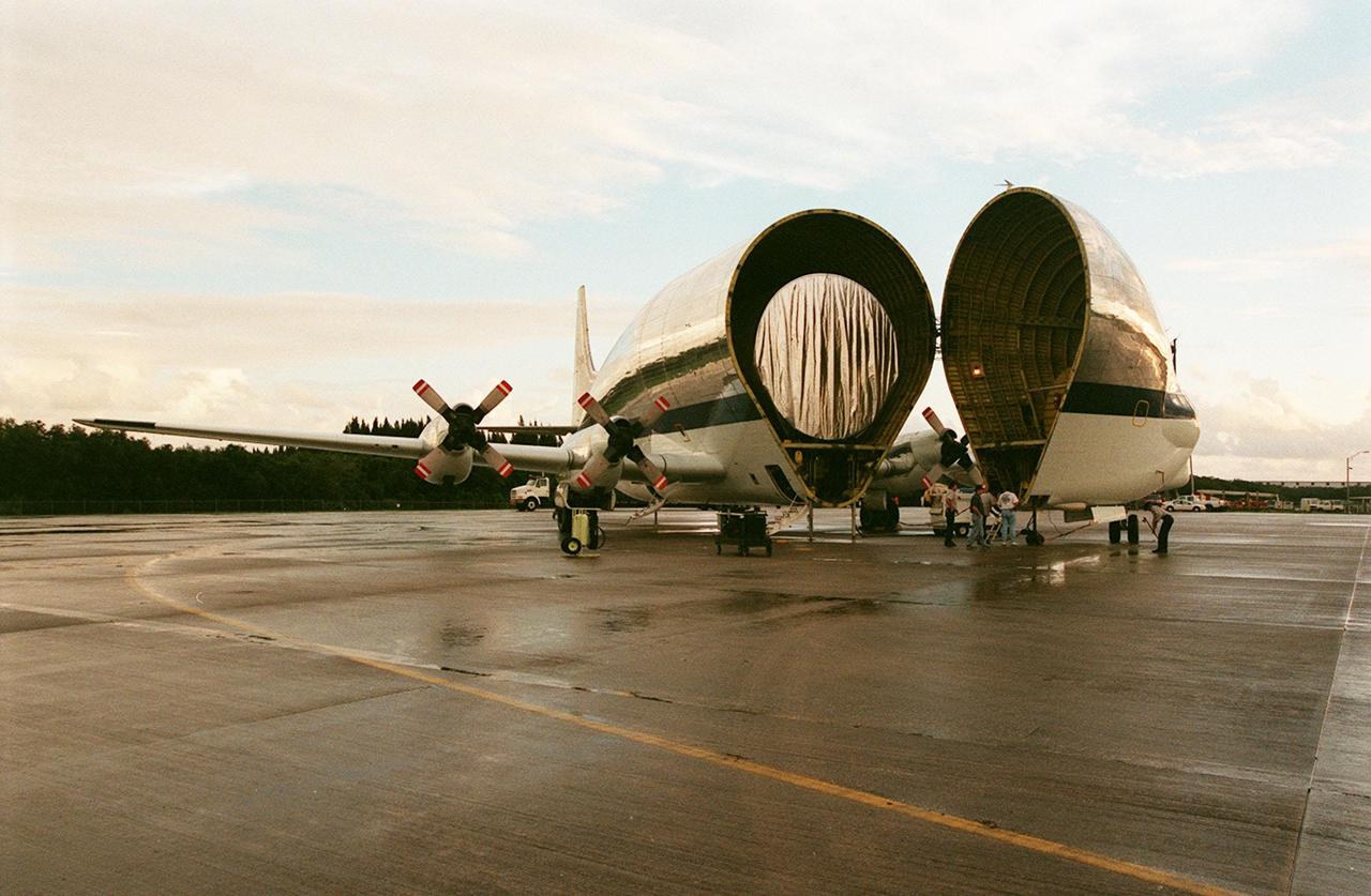
KENNEDY SPACE CENTER, FLA. -- At KSC's Shuttle Landing Facility, NASA's Super Guppy opens to reveal its cargo, the International Space Station's (ISS) S1 truss. Manufactured by the Boeing Co. in Huntington Beach, Calif., this component of the ISS is the first starboard (right-side) truss segment, whose main job is providing structural support for the orbiting research facility's radiator panels that cool the Space Station's complex power system. The S1 truss segment also will house communications systems, external experiment positions and other subsystems. Primarily constructed of aluminum, the truss segment is 45 feet long, 15 feet wide and 6 feet tall. When fully outfitted, it will weigh 31,137 pounds. The truss is slated for flight in 2001. The Super Guppy, with its 25-foot diameter fuselage designed to handle oversized loads, is well prepared to transport the truss and other ISS segments. Loading the Guppy is easy because of the unique "fold-away" nose of the aircraft that opens 110 degrees for cargo loading. A system of rails in the cargo compartment, used with either Guppy pallets or fixtures designed for specific cargo, makes cargo loading simple and efficient. Rollers mounted in the rails allow pallets or fixtures to be moved by an electric winch mounted beneath the cargo floor. Automatic hydraulic lock pins in each rail secure the pallet for flight. The truss is to be transferred to the Operations and Checkout Building
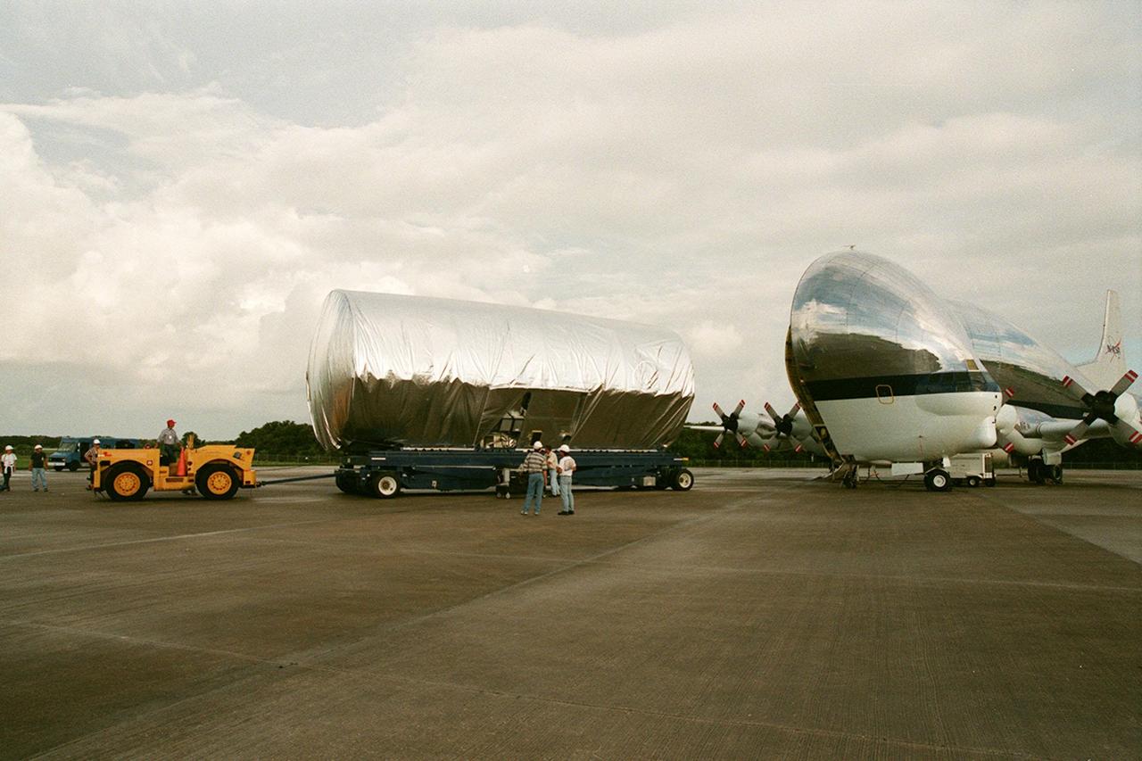
KENNEDY SPACE CENTER, FLA. -- At the Shuttle Landing Facility, the S1 truss, a segment of the International Space Station, is moved away from the Super Guppy that brought it to KSC from Marshall Space Flight Center. Manufactured by the Boeing Co. in Huntington Beach, Calif., this component of the ISS is the first starboard (right-side) truss segment, whose main job is providing structural support for the orbiting research facility's radiator panels that cool the Space Station's complex power system. The S1 truss segment also will house communications systems, external experiment positions and other subsystems. Primarily constructed of aluminum, the truss segment is 45 feet long, 15 feet wide and 6 feet tall. When fully outfitted, it will weigh 31,137 pounds. The truss is slated for flight in 2001. The Super Guppy, with its 25-foot diameter fuselage designed to handle oversized loads, is well prepared to transport the truss and other ISS segments. Loading the Guppy is easy because of the unique "fold-away" nose of the aircraft that opens 110 degrees for cargo loading. A system of rails in the cargo compartment, used with either Guppy pallets or fixtures designed for specific cargo, makes cargo loading simple and efficient. Rollers mounted in the rails allow pallets or fixtures to be moved by an electric winch mounted beneath the cargo floor. Automatic hydraulic lock pins in each rail secure the pallet for flight. The truss is being transferred to the Operations and Checkout Building
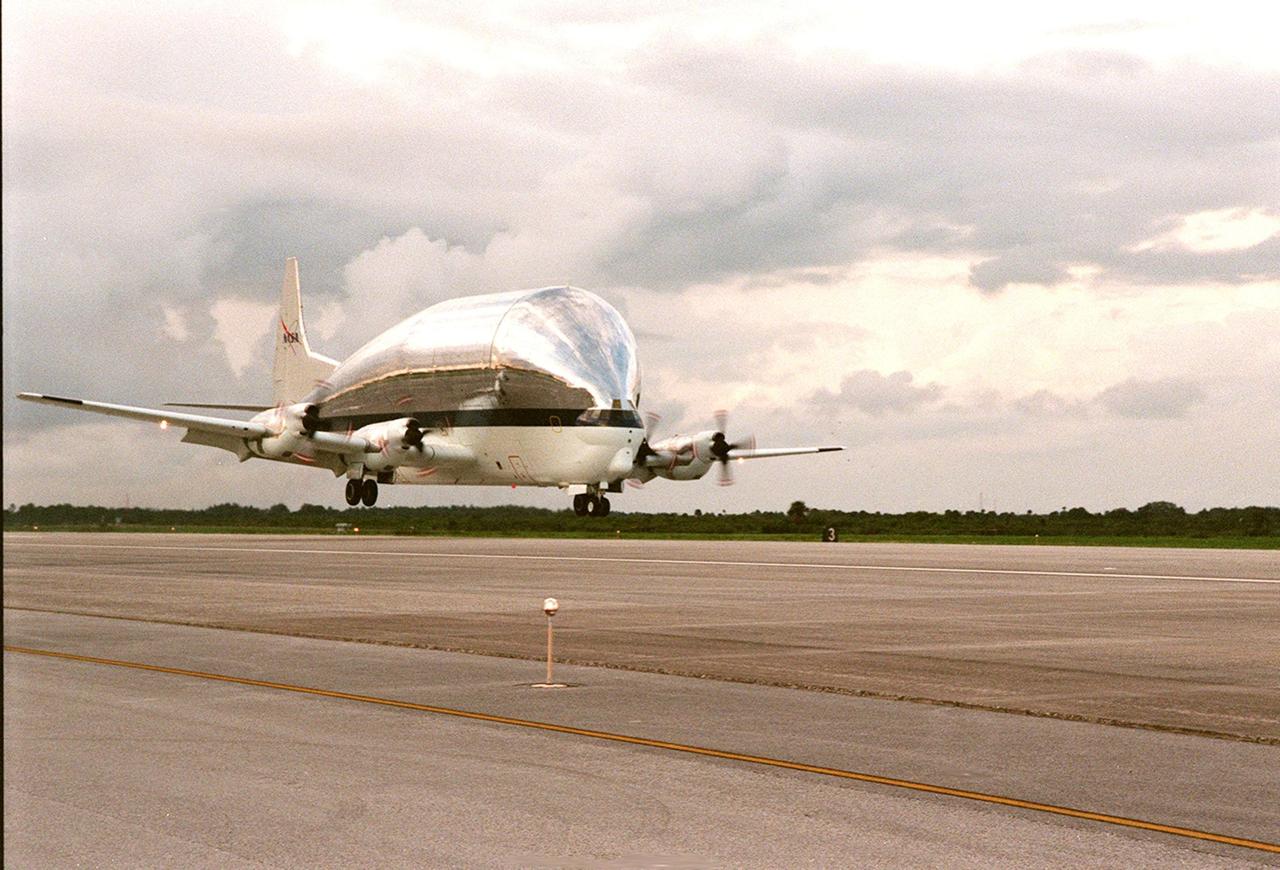
KENNEDY SPACE CENTER, FLA. -- NASA's Super Guppy airplane, with the International Space Station's (ISS) S1 truss aboard, arrives at KSC's Shuttle Landing Facility from Marshall Space Flight Center. Manufactured by the Boeing Co. in Huntington Beach, Calif., this component of the ISS is the first starboard (right-side) truss segment, whose main job is providing structural support for the orbiting research facility's radiator panels that cool the Space Station's complex power system. The S1 truss segment also will house communications systems, external experiment positions and other subsystems. Primarily constructed of aluminum, the truss segment is 45 feet long, 15 feet wide and 6 feet tall. When fully outfitted, it will weigh 31,137 pounds. The truss is slated for flight in 2001. The Super Guppy, with its 25-foot diameter fuselage designed to handle oversized loads, is well prepared to transport the truss and other ISS segments. Loading the Guppy is easy because of the unique "fold-away" nose of the aircraft that opens 110 degrees for cargo loading. A system of rails in the cargo compartment, used with either Guppy pallets or fixtures designed for specific cargo, makes cargo loading simple and efficient. Rollers mounted in the rails allow pallets or fixtures to be moved by an electric winch mounted beneath the cargo floor. Automatic hydraulic lock pins in each rail secure the pallet for flight. The truss is to be moved to the Operations and Checkout Building
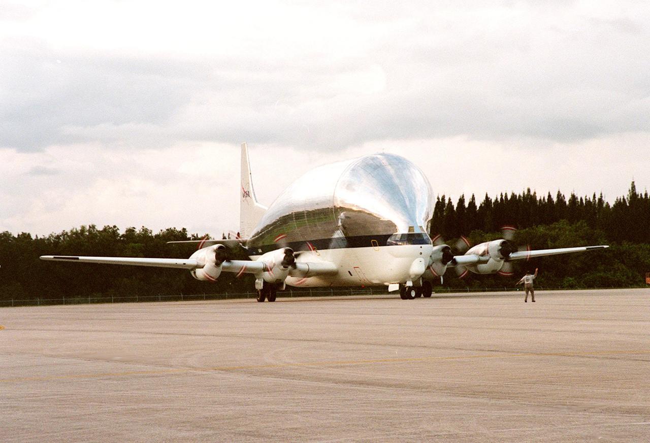
KENNEDY SPACE CENTER, FLA. -- NASA's Super Guppy airplane, with the International Space Station's (ISS) S1 truss aboard, rolls to a stop at KSC's Shuttle Landing Facility. Manufactured by the Boeing Co. in Huntington Beach, Calif., this component of the ISS is the first starboard (right-side) truss segment, whose main job is providing structural support for the orbiting research facility's radiator panels that cool the Space Station's complex power system. The S1 truss segment also will house communications systems, external experiment positions and other subsystems. Primarily constructed of aluminum, the truss segment is 45 feet long, 15 feet wide and 6 feet tall. When fully outfitted, it will weigh 31,137 pounds. The truss is slated for flight in 2001. The Super Guppy, with its 25-foot diameter fuselage designed to handle oversized loads, is well prepared to transport the truss and other ISS segments. Loading the Guppy is easy because of the unique "fold-away" nose of the aircraft that opens 110 degrees for cargo loading. A system of rails in the cargo compartment, used with either Guppy pallets or fixtures designed for specific cargo, makes cargo loading simple and efficient. Rollers mounted in the rails allow pallets or fixtures to be moved by an electric winch mounted beneath the cargo floor. Automatic hydraulic lock pins in each rail secure the pallet for flight. The truss is to be transferred to the Operations and Checkout Building