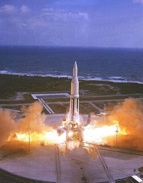
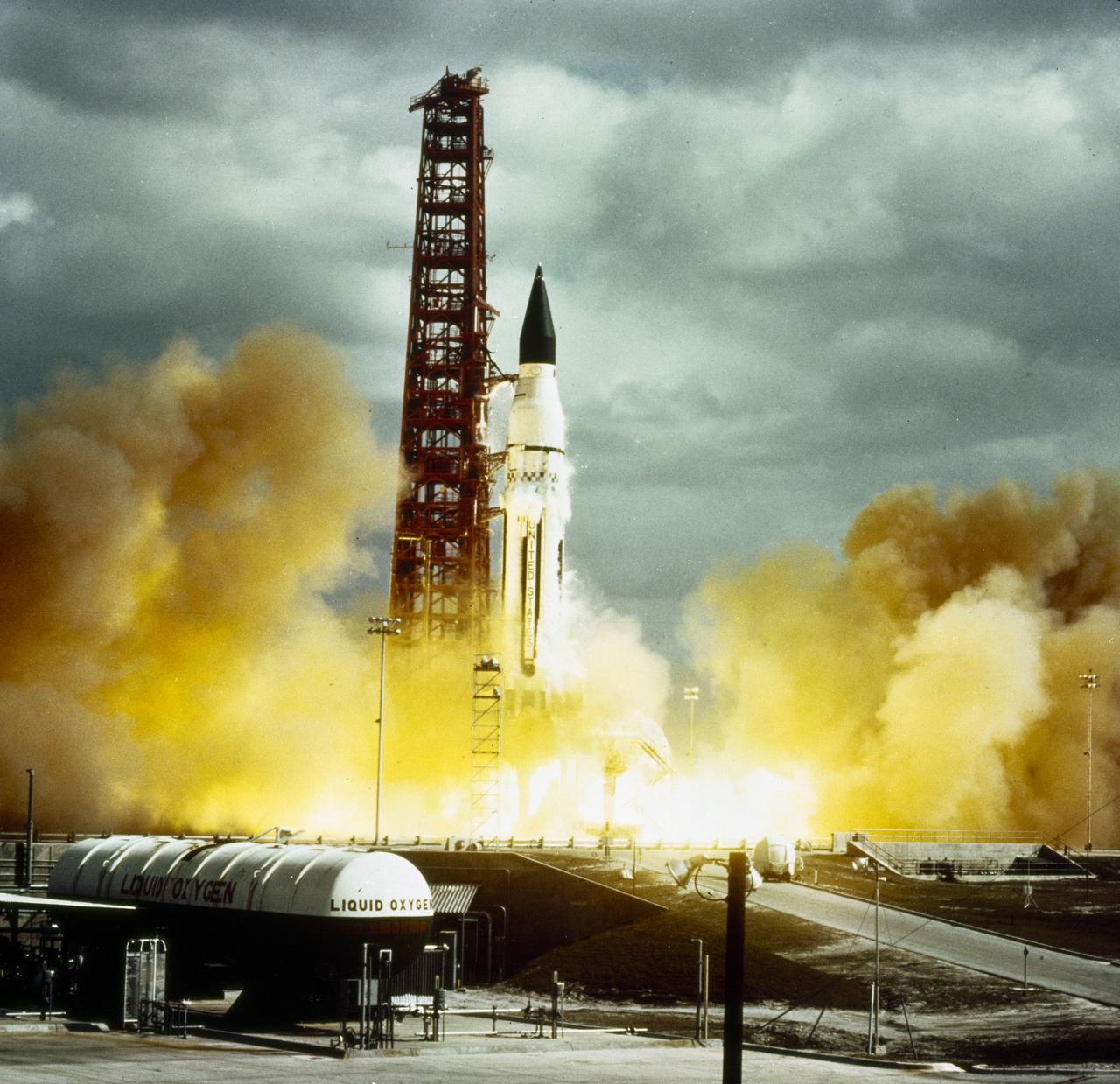
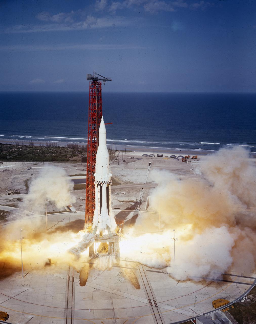
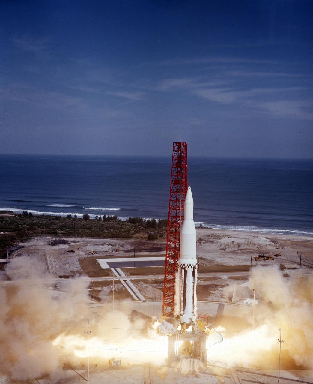
The Marshall Space Flight Center's first Saturn I vehicle, SA-1, lifts off from Cape Canaveral, Florida, on October 27, 1961. This early configuration, Saturn I Block I, 162 feet tall and weighing 460 tons, consisted of the eight H-1 engines S-I stage and the dummy second stage (S-IV stage).
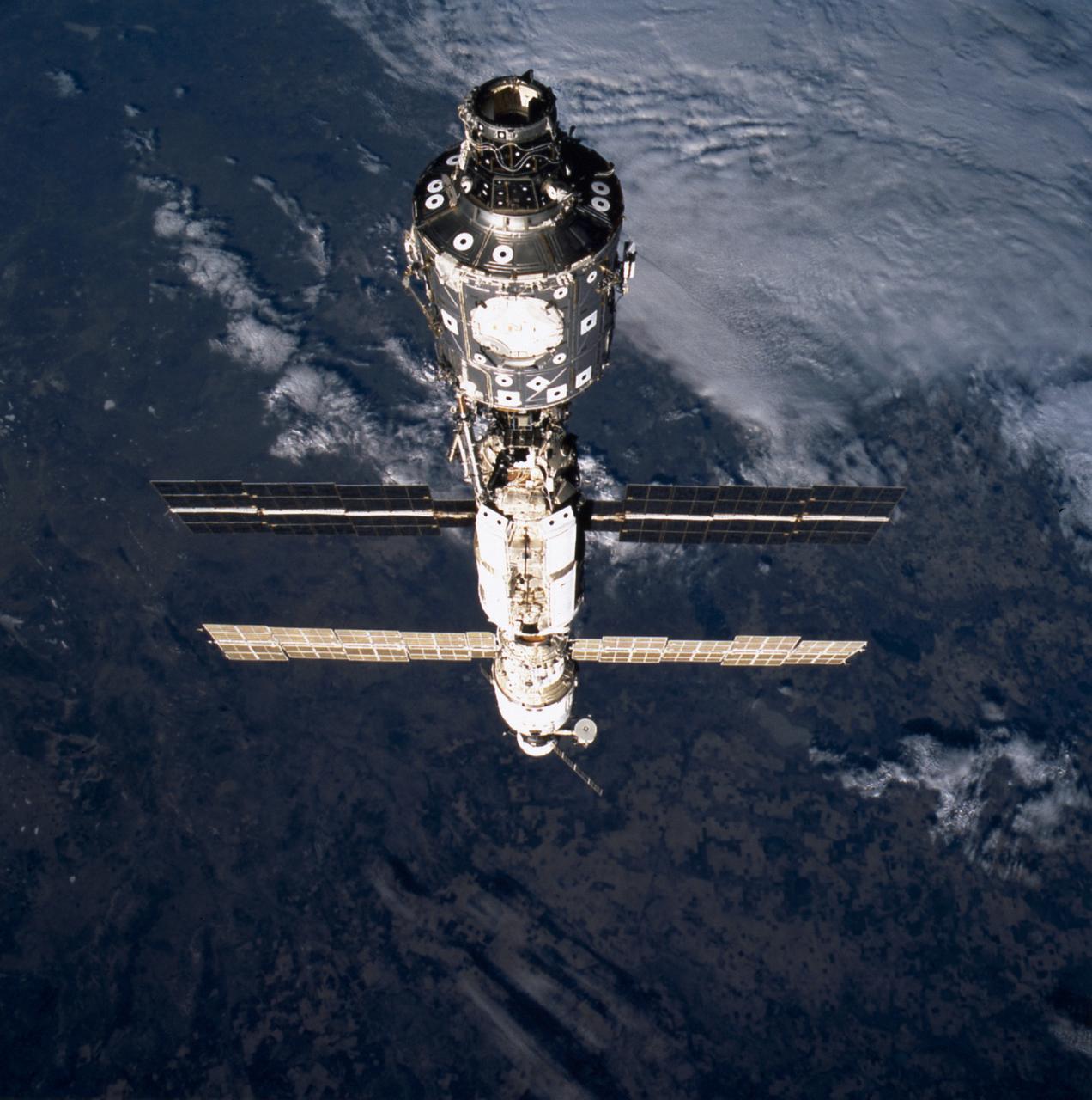
This image of the International Space Station (ISS) was taken during the STS-106 mission. The ISS component nearest the camera is the U.S. built Node 1 or Unity module, which cornected with the Russian built Functional Cargo Block (FGB) or Zarya. The FGB was linked with the Service Module or Zvezda. On the far end is the Russian Progress supply ship.

ISS034-E-021232 (10 Jan. 2013) --- Russian cosmonaut Evgeny Tarelkin, Expedition 34 flight engineer, looks at his watch while using the Liulin-5 Electronic Block behind a panel in the Rassvet Mini-Research Module 1 (MRM1) of the International Space Station.
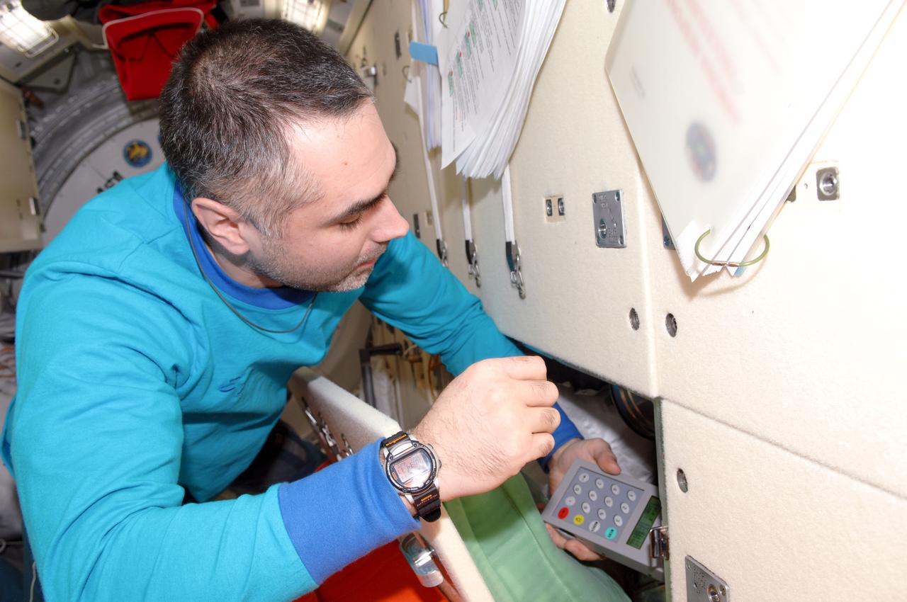
ISS034-E-021230 (10 Jan. 2013) --- Russian cosmonaut Evgeny Tarelkin, Expedition 34 flight engineer, uses the Liulin-5 Electronic Block behind a panel in the Rassvet Mini-Research Module 1 (MRM1) of the International Space Station.
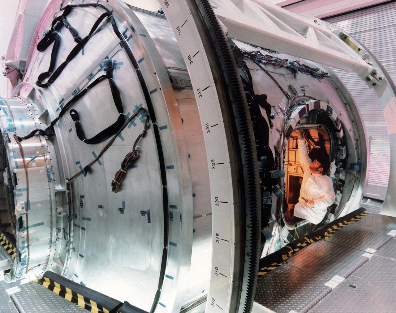
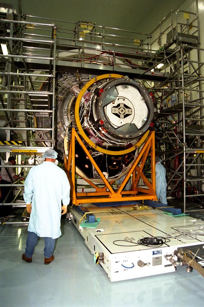
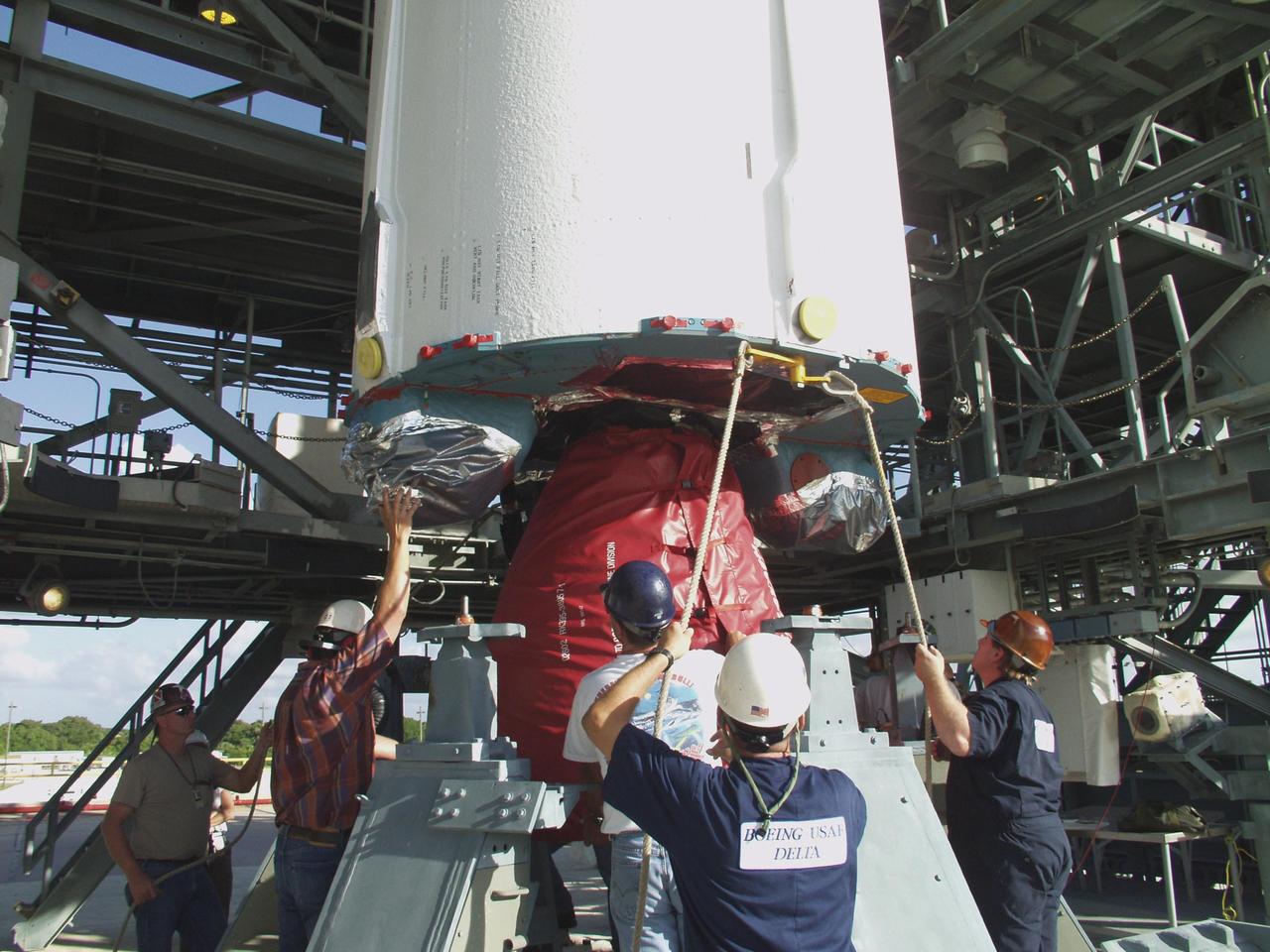
This photograph, taken by the Boeing Company,shows Boeing technicians preparing to install one of six hatches or doors to the Node 1 (also called Unity), the first U.S. Module for the International Space Station (ISS). The Node 1, or Unity, serves as a cornecting passageway to Space Station modules and was manufactured by the Boeing Company at the Marshall Space Flight Center from 1994 to 1997. The U.S. built Unity module was launched aboard the orbiter Endeavour (STS-88 mission) on December 4, 1998 and connected to the Zarya, the Russian-built Functional Energy Block (FGB). The Zarya was launched on a Russian proton rocket prior to the launch of the Unity. The ISS is a multidisciplinary laboratory, technology test bed, and observatory that will provide unprecedented undertakings in scientific, technological, and international experimentation.
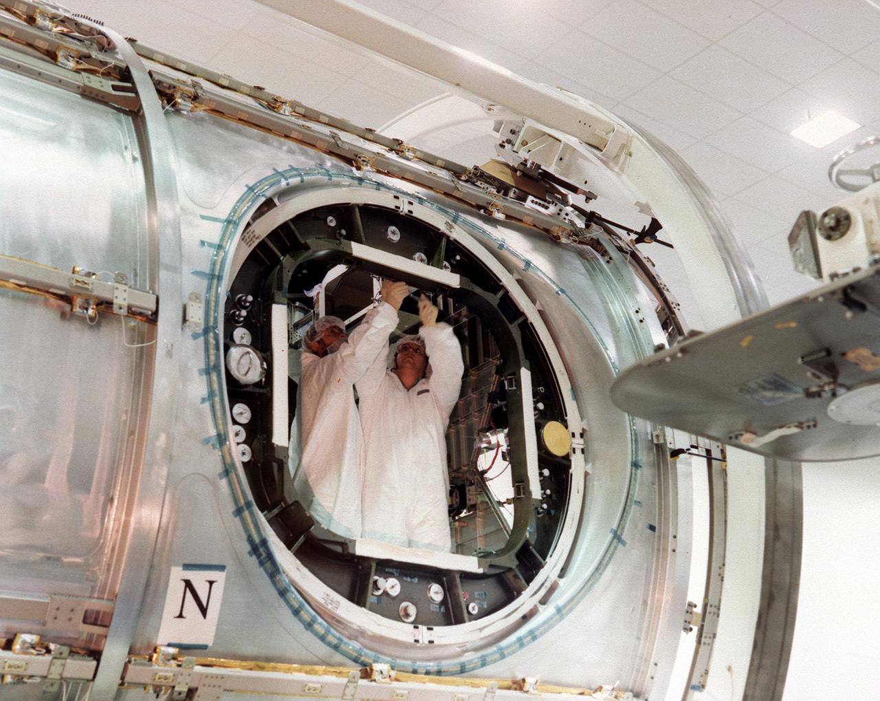
This photograph, taken by the Boeing Company, shows Boeing technicians preparing to install one of six hatches or doors to the Node 1 (also called Unity), the first U.S. Module for the International Space Station (ISS). The Node 1, or Unity, serves as a cornecting passageway to Space Station modules and was manufactured by the Boeing Company at the Marshall Space Flight Center from 1994 to 1997. The U.S. built Unity module was launched aboard the orbiter Endeavour (STS-88 mission) on December 4, 1998 and connected to the Zarya, the Russian-built Functional Energy Block (FGB). The Zarya was launched on a Russian proton rocket prior to the launch of the Unity. The ISS is a multidisciplinary laboratory, technology test bed, and observatory that will provide unprecedented undertakings in scientific, technological, and international experimentation.
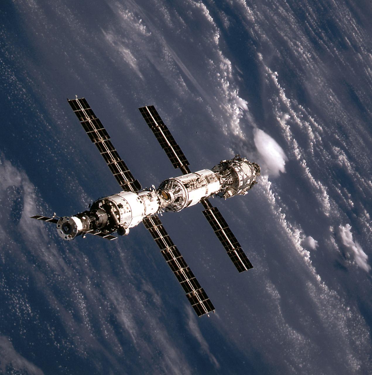
This image of the International Space Station (ISS) was taken when Space Shuttle Atlantis (STS-106 mission) approached the ISS for docking. At the top is the Russian Progress supply ship that is linked with the Russian built Service Module or Zvezda. The Zvezda is cornected with the Russian built Functional Cargo Block (FGB) or Zarya. The U.S. built Node 1 or Unity module is seen at the bottom.
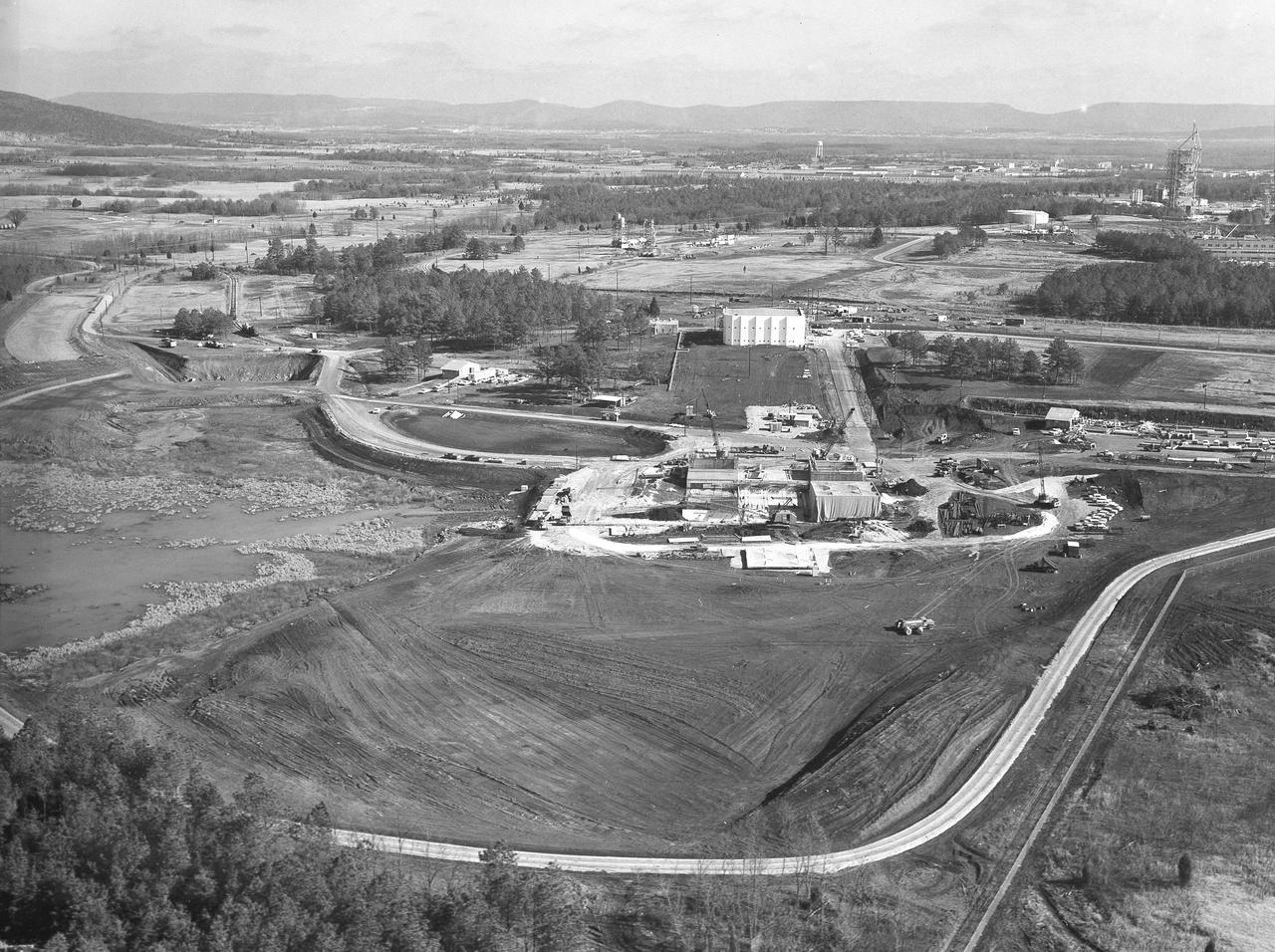
At its founding, the Marshall Space Flight Center (MSFC) inherited the Army’s Jupiter and Redstone test stands, but much larger facilities were needed for the giant stages of the Saturn V. From 1960 to 1964, the existing stands were remodeled and a sizable new test area was developed. The new comprehensive test complex for propulsion and structural dynamics was unique within the nation and the free world, and they remain so today because they were constructed with foresight to meet the future as well as on going needs. Construction of the S-IC Static test stand complex began in 1961 in the west test area of MSFC, and was completed in 1964. The S-IC static test stand was designed to develop and test the 138-ft long and 33-ft diameter Saturn V S-IC first stage, or booster stage, weighing in at 280,000 pounds. Required to hold down the brute force of a 7,500,000-pound thrust produced by 5 F-1 engines, the S-IC static test stand was designed and constructed with the strength of hundreds of tons of steel and 12,000,000 pounds of cement, planted down to bedrock 40 feet below ground level. The foundation walls, constructed with concrete and steel, are 4 feet thick. The base structure consists of four towers with 40-foot-thick walls extending upward 144 feet above ground level. The structure was topped by a crane with a 135-foot boom. With the boom in the upright position, the stand was given an overall height of 405 feet, placing it among the highest structures in Alabama at the time. In addition to the stand itself, related facilities were constructed during this time. Built directly east of the test stand was the Block House, which served as the control center for the test stand. The two were connected by a narrow access tunnel which housed the cables for the controls. The F-1 Engine test stand was built north of the massive S-IC test stand. The F-1 test stand is a vertical engine firing test stand, 239 feet in elevation and 4,600 square feet in area at the base, and was designed to assist in the development of the F-1 Engine. Capability is provided for static firing of 1.5 million pounds of thrust using liquid oxygen and kerosene. Like the S-IC stand, the foundation of the F-1 stand is keyed into the bedrock approximately 40 feet below grade. This aerial photograph, taken January 15, 1963, gives a close overall view of the newly developed test complex. Depicted in the forefront center is the S-IC test stand with towers prominent, the Block House is seen in the center just above the S-IC test stand, and the large hole to the left, located midway between the two is the F-1 test stand site.
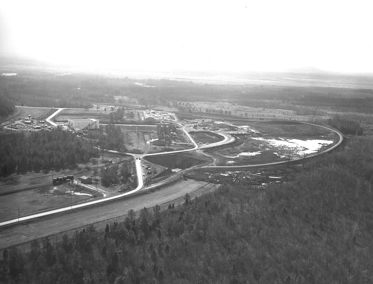
At its founding, the Marshall Space Flight Center (MSFC) inherited the Army’s Jupiter and Redstone test stands, but much larger facilities were needed for the giant stages of the Saturn V. From 1960 to 1964, the existing stands were remodeled and a sizable new test area was developed. The new comprehensive test complex for propulsion and structural dynamics was unique within the nation and the free world, and they remain so today because they were constructed with foresight to meet the future as well as on going needs. Construction of the S-IC Static test stand complex began in 1961 in the west test area of MSFC, and was completed in 1964. The S-IC static test stand was designed to develop and test the 138-ft long and 33-ft diameter Saturn V S-IC first stage, or booster stage, weighing in at 280,000 pounds. Required to hold down the brute force of a 7,500,000-pound thrust produced by 5 F-1 engines, the S-IC static test stand was designed and constructed with the strength of hundreds of tons of steel and 12,000,000 pounds of cement, planted down to bedrock 40 feet below ground level. The foundation walls, constructed with concrete and steel, are 4 feet thick. The base structure consists of four towers with 40-foot-thick walls extending upward 144 feet above ground level. The structure was topped by a crane with a 135-foot boom. With the boom in the upright position, the stand was given an overall height of 405 feet, placing it among the highest structures in Alabama at the time. In addition to the stand itself, related facilities were constructed during this time. Built directly east of the test stand was the Block House, which served as the control center for the test stand. The two were connected by a narrow access tunnel which housed the cables for the controls. The F-1 Engine test stand was built north of the massive S-IC test stand. The F-1 test stand is a vertical engine firing test stand, 239 feet in elevation and 4,600 square feet in area at the base, and was designed to assist in the development of the F-1 Engine. Capability is provided for static firing of 1.5 million pounds of thrust using liquid oxygen and kerosene. Like the S-IC stand, the foundation of the F-1 stand is keyed into the bedrock approximately 40 feet below grade. Looking North, this aerial taken January 15, 1963, gives a closer view of the deep hole for the F-1 test stand site in the forefront. The S-IC test stand with towers prominent is to the right of center, and the Block House is seen left of center.
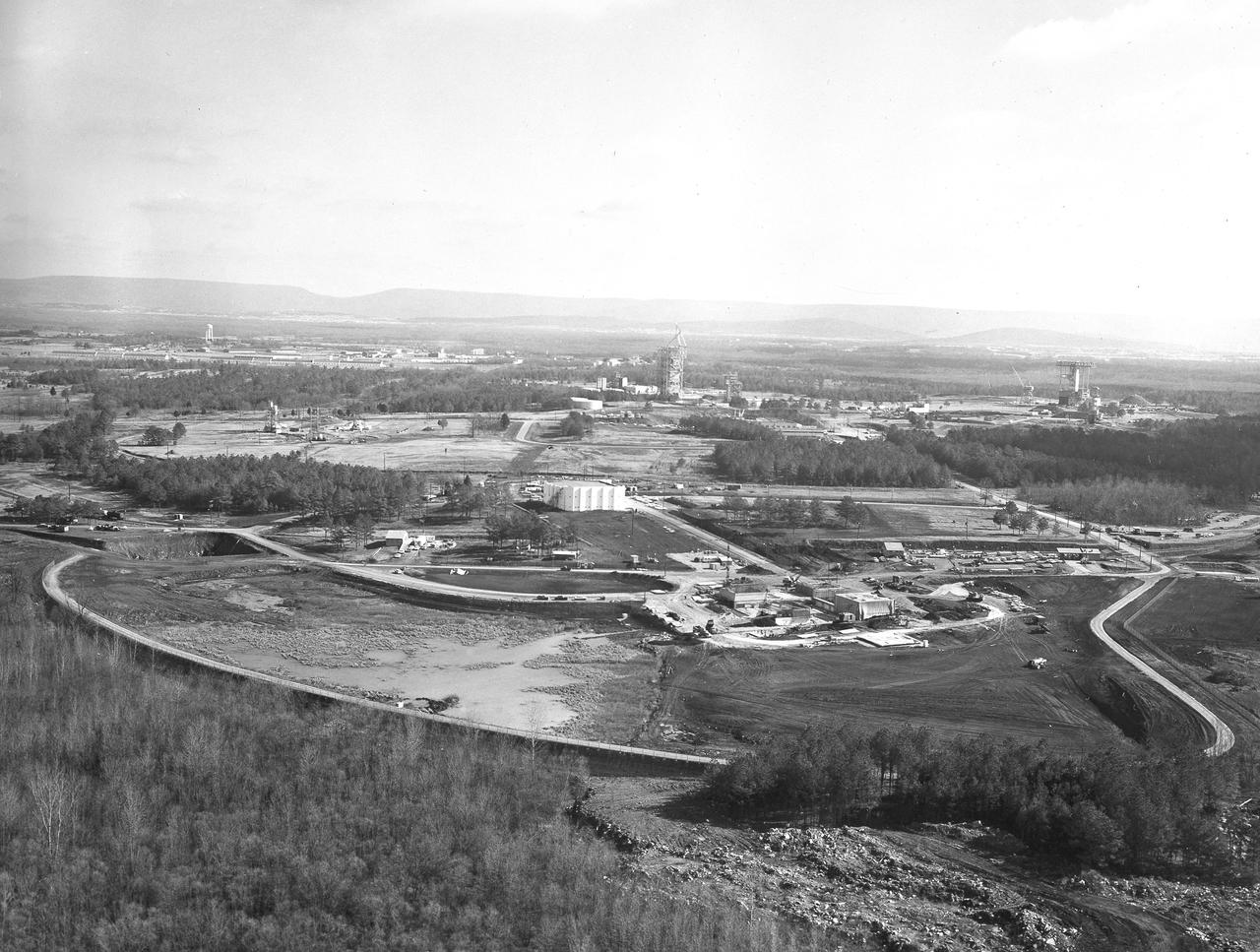
At its founding, the Marshall Space Flight Center (MSFC) inherited the Army’s Jupiter and Redstone test stands, but much larger facilities were needed for the giant stages of the Saturn V. From 1960 to 1964, the existing stands were remodeled and a sizable new test area was developed. The new comprehensive test complex for propulsion and structural dynamics was unique within the nation and the free world, and they remain so today because they were constructed with foresight to meet the future as well as on going needs. Construction of the S-IC Static test stand complex began in 1961 in the west test area of MSFC, and was completed in 1964. The S-IC static test stand was designed to develop and test the 138-ft long and 33-ft diameter Saturn V S-IC first stage, or booster stage, weighing in at 280,000 pounds. Required to hold down the brute force of a 7,500,000-pound thrust produced by 5 F-1 engines, the S-IC static test stand was designed and constructed with the strength of hundreds of tons of steel and 12,000,000 pounds of cement, planted down to bedrock 40 feet below ground level. The foundation walls, constructed with concrete and steel, are 4 feet thick. The base structure consists of four towers with 40-foot-thick walls extending upward 144 feet above ground level. The structure was topped by a crane with a 135-foot boom. With the boom in the upright position, the stand was given an overall height of 405 feet, placing it among the highest structures in Alabama at the time. In addition to the stand itself, related facilities were constructed during this time. Built directly east of the test stand was the Block House, which served as the control center for the test stand. The two were connected by a narrow access tunnel which housed the cables for the controls. The F-1 Engine test stand was built north of the massive S-IC test stand. The F-1 test stand is a vertical engine firing test stand, 239 feet in elevation and 4,600 square feet in area at the base, and was designed to assist in the development of the F-1 Engine. Capability is provided for static firing of 1.5 million pounds of thrust using liquid oxygen and kerosene. Like the S-IC stand, the foundation of the F-1 stand is keyed into the bedrock approximately 40 feet below grade. This aerial photograph, taken January 15, 1963 gives an overall view of the construction progress of the newly developed test complex. The large white building located in the center is the Block House. Just below and to the right of it is the S-IC test stand. The large hole to the left of the S-IC stand is the F-1 test stand site.
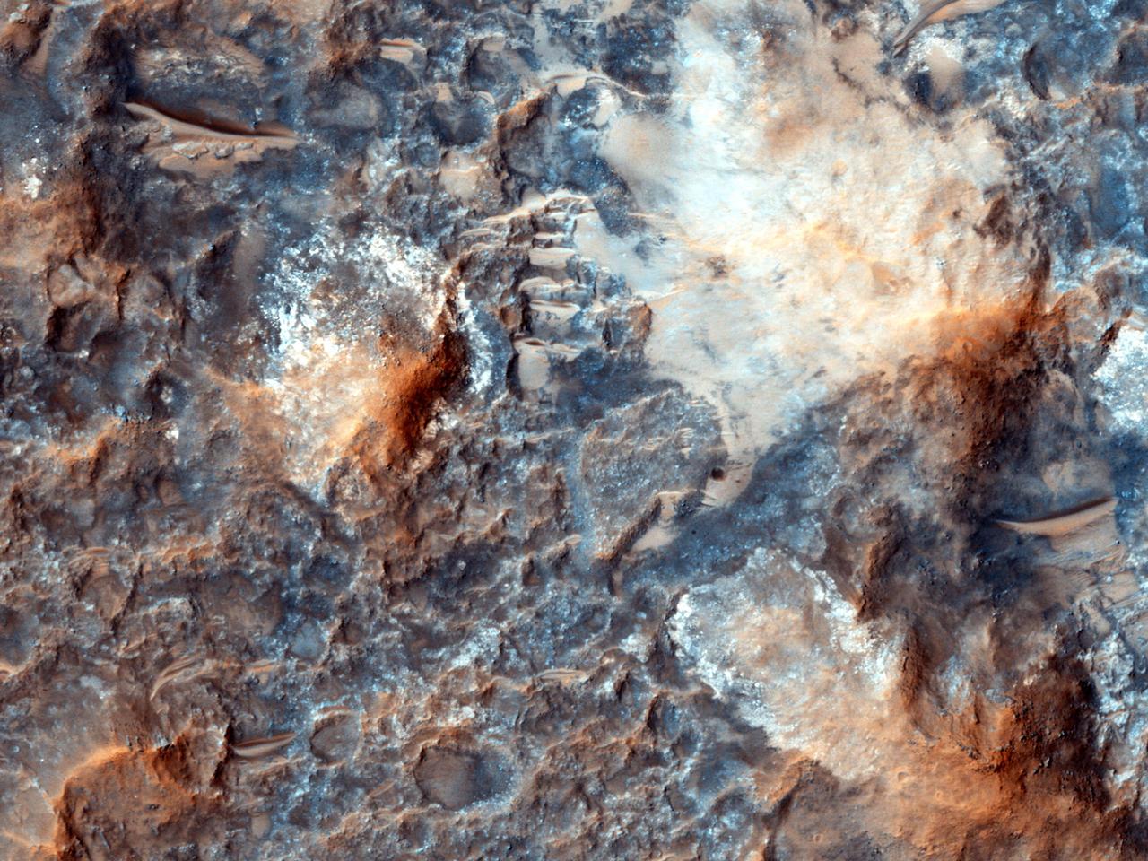
Megabreccia is a term used to describe jumbled, fragmented blocks of rock larger than 1 meter 1.09 yard across. This image was observed by NASA Mars Reconnaissance Orbiter.
NASA Mars Exploration Rover Opportunity used its microscopic imager to get this view of the surface of a rock called Block Island during the 1,963rd Martian day, or sol, of the rover mission on Mars Aug. 1, 2009.

This image, taken by NASA Dawn spacecraft on Jan. 1, 2016, shows two relatively young, fresh craters on Ceres. Large blocks of ejected material fell near the rims of the craters and onto the floor of the larger crater.
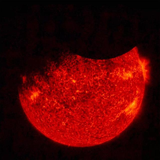
NASA's Solar Dynamics Observatory (SDO) saw both the Moon (upper right) and the Earth (upper left) partially block the sun (Sept. 1, 2016 at 7:33 UT). Just before this image was taken, the Earth totally blocked the sun for a while. SDO orbits 22,000 miles above the Earth in a highly elliptical orbit that sometimes puts the Moon or Earth in front of the sun. The sun image was taken in a wavelength of extreme ultraviolet light. Only once before have both been there at the same time. Note that the edge of the moon is quite crisp because it has no atmosphere. Movies are available at the Photojournal. http://photojournal.jpl.nasa.gov/catalog/PIA21028
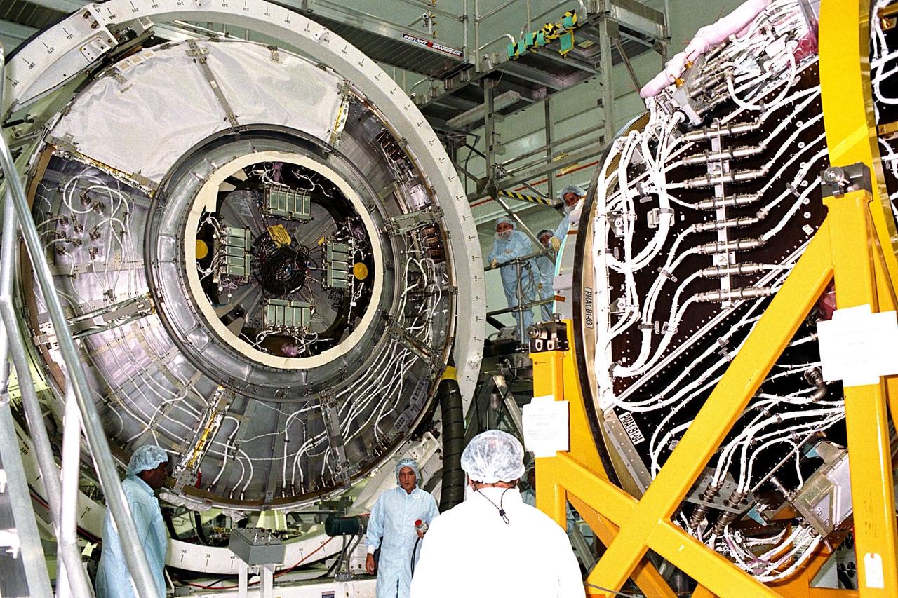
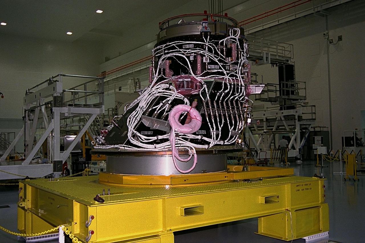
International Space Station (ISS) contractors erect access scaffolding around the Pressurized Mating Adapter-1 (PMA-1) for the ISS in KSC’s Space Station Processing Facility. A PMA is a cone-shaped connector that will be attached to Node 1, the space station’s structural building block, during ground processing. The white flight cables around PMA-1 will assist in connecting the node to the U.S.-financed, Russian-built Functional Cargo Block, a component that supplies early power and propulsion systems for the station. Node 1 with two adapters attached will be the first element of the station to be launched aboard the Space Shuttle Endeavour on STS-88 in July 1998
International Space Station (ISS) contractors erect access scaffolding around the Pressurized Mating Adapter-1 (PMA-1) for the ISS in KSC’s Space Station Processing Facility. A PMA is a cone-shaped connector that will be attached to Node 1, the space station’s structural building block, during ground processing. The white flight cables around PMA-1 will assist in connecting the node to the U.S.-financed, Russian-built Functional Cargo Block, a component that supplies early power and propulsion systems for the station. Node 1 with two adapters attached will be the first element of the station to be launched aboard the Space Shuttle Endeavour on STS-88 in July 1998
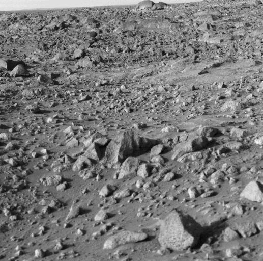
NASA's Viking 1 took this high-resolution picture today, its third day on Mars. Distance from the camera to the nearfield (bottom) is about 4 meters (13 feet); to the horizon, about 3 kilometers (1.8 miles). The photo shows numerous angular blocks ranging in size from a few centimeters to several meters. The surface between the blocks is composed of fine-grained material. Accumulation of some fine-grained material behind blocks indicates wind deposition of dust and sand downwind of obstacles. The large block on the horizon is about 4 meters (13 feet) wide. Distance across the horizon is about 34 meters (110 feet). http://photojournal.jpl.nasa.gov/catalog/PIA00385
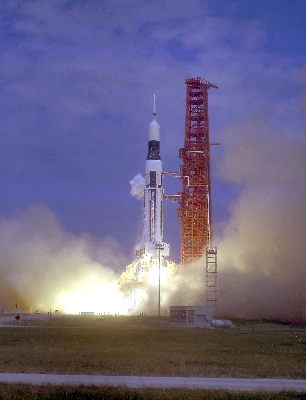
The launch of the SA-7 (Saturn I Block II) was on September 18, 1964. The SA-7 mission was the second orbital flight of the S-IV stage (second stage) with the payload consisting of the Apollo command and service module's instrument unit. The Saturn I Block II vehicle had two live stages, and were basically in the two-stage configuration of the Saturn I vehicle. While the tank arrangement and the engine patterns were the same, there were marked changes between the Block I and II versions. The first stage (S-I stage) was an improved version of the Block I S-I stage. The Block II S-1 stage had eight fins added for greater aerodynamic stability in the lower atmosphere.
Developed at MSFC under the direction of Dr. Wernher von Braun, the SA-5 incorporated a Saturn I, Block II engine. Launched on January 29, 1964, SA-5 was the first two stage (Block II) Saturn with orbital capability and performed the first test of Instrument Unit and successful stage separation. Block II vehicles had two live stages, and were basically in the two-stage configuration of the Saturn I vehicle. There were marked changes between the Block I and II versions. The Block II S-I stage had eight fins added for greater aerodynamic stability in the lower atmosphere. All Block II H-1 engines had a thrust of 188,000 pounds each for a combined thrust over 1,500,000 pounds. The Block II second stage (S-IV) had six RL-10 hydrogen-oxygen engines, each producing a thrust of 15,000 pounds for a total combined thrust of 90,000 pounds. A motion picture camera capsule loated on stage I was successful recovered.
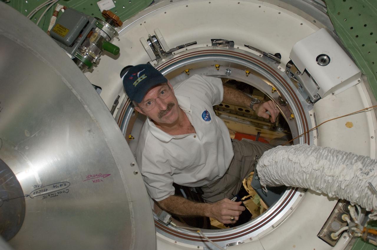
ISS030-E-050953 (27 Jan. 2012) --- NASA astronaut Dan Burbank, Expedition 30 commander, is pictured in a hatch as he exits the Rassvet Mini-Research Module 1 (MRM-1) into the Zarya Functional Cargo Block (FGB) transfer compartment of the International Space Station.
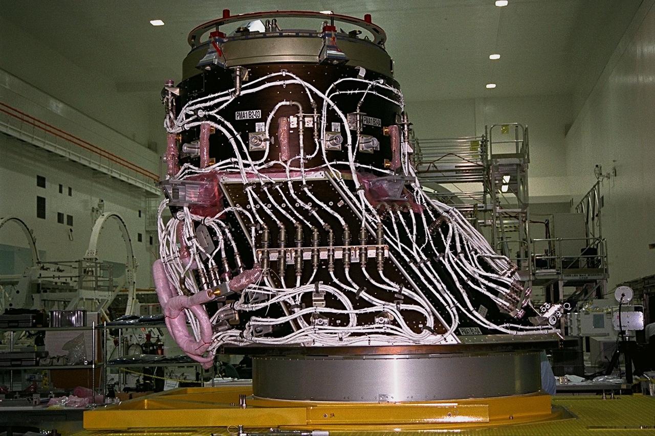
The first of two Pressurized Mating Adapters, or PMAs, for the International Space Station arrive in KSC’s Space Station Processing Facility in July. A PMA is a cone-shaped connector that will be attached to Node 1, the space station’s structural building block, during ground processing. The adapter will house space station computers and various electrical support equipment and eventually will serve as the passageway for astronauts between the node and the U.S-financed, Russian-built Functional Cargo Block. Node 1 with two adapters attached will be the first element of the station to be launched aboard the Space Shuttle Endeavour on STS-88 in July 1998

The first of two Pressurized Mating Adapters, or PMAs, for the International Space Station arrive in KSC’s Space Station Processing Facility in July. A PMA is a cone-shaped connector that will be attached to Node 1, the space station’s structural building block, during ground processing. The adapter will house space station computers and various electrical support equipment and eventually will serve as the passageway for astronauts between the node and the U.S-financed, Russian-built Functional Cargo Block. Node 1 with two adapters attached will be the first element of the station to be launched aboard the Space Shuttle Endeavour on STS-88 in July 1998
![This image from NASA's Mars Reconnaissance Orbiter (MRO) shows blocks of layered terrain within the Olympus Mons aureole. The aureole is a giant apron of chaotic material around the volcano, perhaps formed by enormous landslides off the flanks of the giant volcano. These blocks of layered material have been eroded by the wind into the scenic landscape we see here. The map is projected here at a scale of 25 centimeters (9.8 inches) per pixel. [The original image scale is 28.3 centimeters (11.1 inches) per pixel (with 1 x 1 binning); objects on the order of 85 centimeters (33.5 inches) across are resolved.] North is up. https://photojournal.jpl.nasa.gov/catalog/PIA22181](https://images-assets.nasa.gov/image/PIA22181/PIA22181~medium.jpg)
This image from NASA's Mars Reconnaissance Orbiter (MRO) shows blocks of layered terrain within the Olympus Mons aureole. The aureole is a giant apron of chaotic material around the volcano, perhaps formed by enormous landslides off the flanks of the giant volcano. These blocks of layered material have been eroded by the wind into the scenic landscape we see here. The map is projected here at a scale of 25 centimeters (9.8 inches) per pixel. [The original image scale is 28.3 centimeters (11.1 inches) per pixel (with 1 x 1 binning); objects on the order of 85 centimeters (33.5 inches) across are resolved.] North is up. https://photojournal.jpl.nasa.gov/catalog/PIA22181
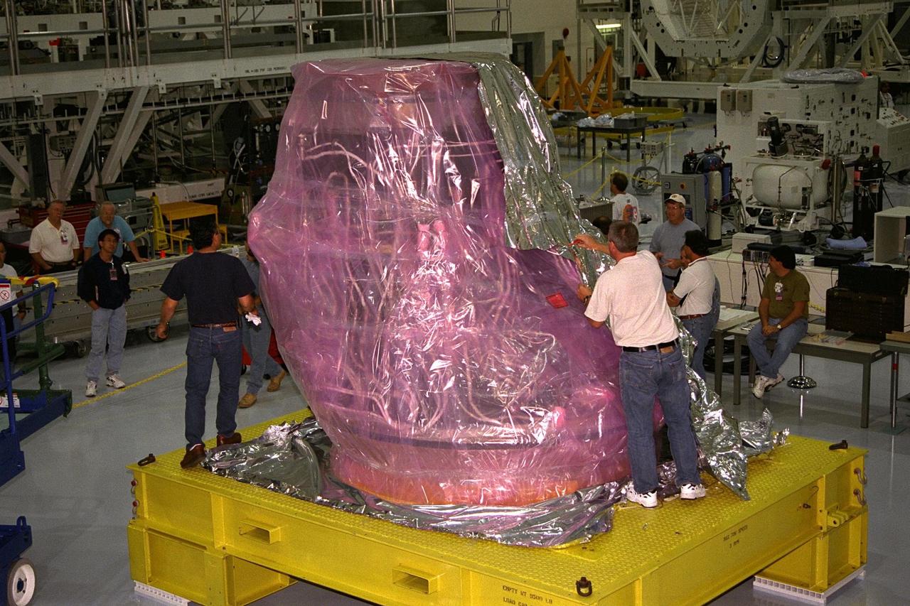
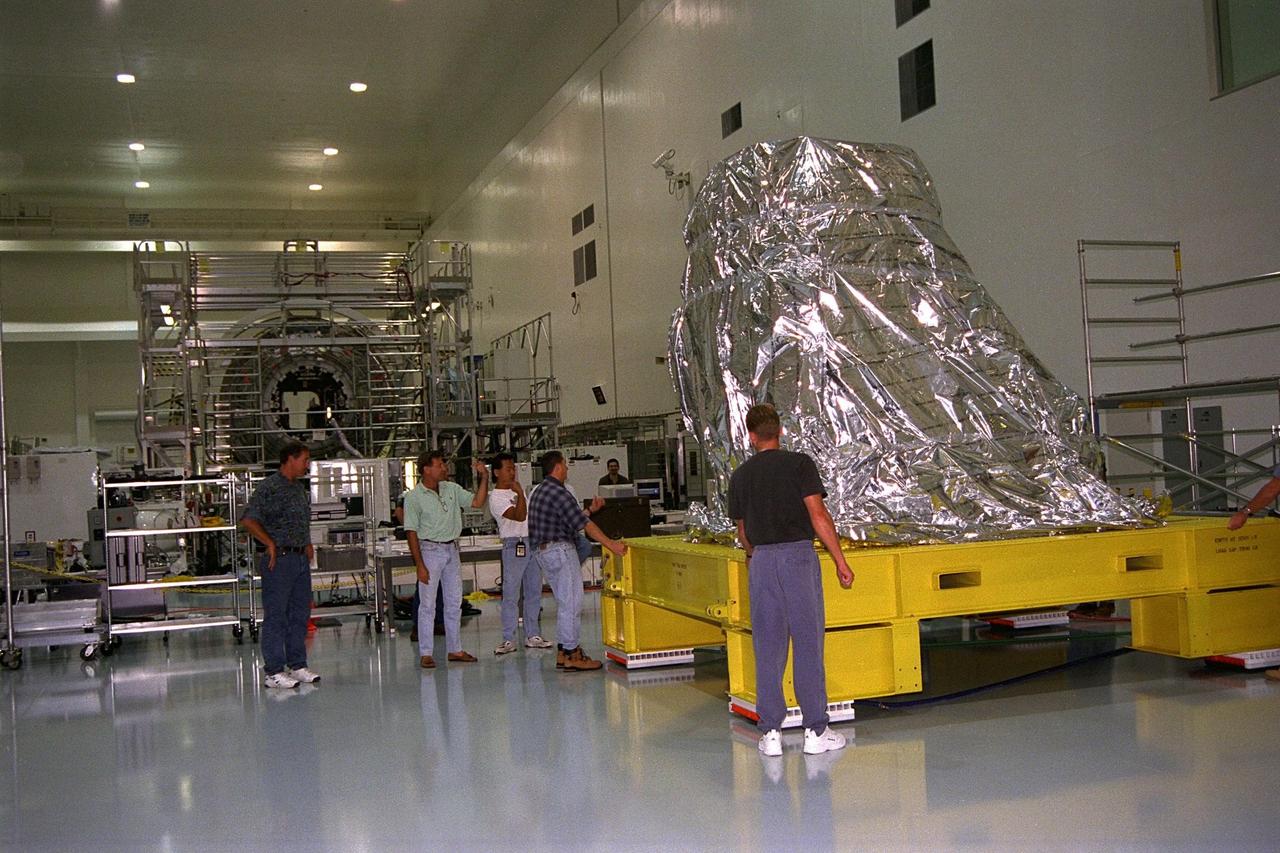
International Space Station (ISS) contractors unwrap Pressurized Mating Adapter-1 (PMA-1) for the ISS in KSC’s Space Station Processing Facility. A PMA is a cone-shaped connector that will be attached to Node 1, the space station’s structural building block, during ground processing. Node 1 with two PMAs attached will be the first element of the station scheduled to be launched aboard the Space Shuttle Endeavour on STS-88 in July 1998
KENNEDY SPACE CENTER, FLA. -- The Pressurized Mating Adapter-1 (PMA-1) for the International Space Station is moved for further processing in KSC’s Space Station Processing Facility. A PMA is a cone-shaped connector that will be attached to Node 1, the space station’s structural building block, during ground processing. Node 1 with two PMAs attached will be the first element of the station scheduled to be launched aboard the Space Shuttle Endeavour on STS-88 in July 1998.
KENNEDY SPACE CENTER, FLA. -- The Pressurized Mating Adapter-1 (PMA-1) for the International Space Station is moved for further processing in KSC’s Space Station Processing Facility. A PMA is a cone-shaped connector that will be attached to Node 1, the space station’s structural building block, during ground processing. Node 1 with two PMAs attached will be the first element of the station scheduled to be launched aboard the Space Shuttle Endeavour on STS-88 in July 1998
KENNEDY SPACE CENTER, FLA. -- The Pressurized Mating Adapter-1 (PMA-1) for the International Space Station is moved for further processing in KSC’s Space Station Processing Facility. A PMA is a cone-shaped connector that will be attached to Node 1, the space station’s structural building block, during ground processing. Node 1 with two PMAs attached will be the first element of the station scheduled to be launched aboard the Space Shuttle Endeavour on STS-88 in July 1998
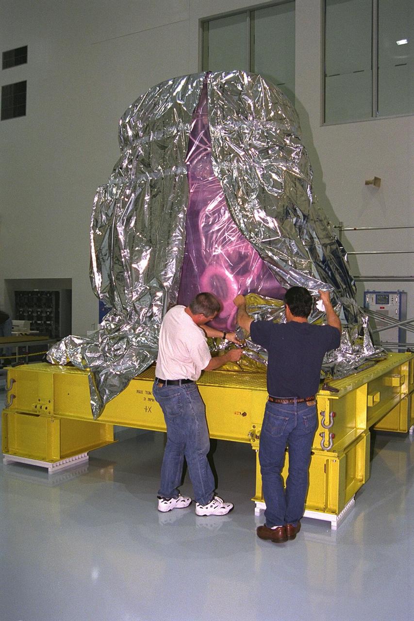
International Space Station (ISS) contractors unwrap Pressurized Mating Adapter-1 (PMA-1) for the ISS in KSC’s Space Station Processing Facility. A PMA is a cone-shaped connector that will be attached to Node 1, the space station’s structural building block, during ground processing. Node 1 with two PMAs attached will be the first element of the station scheduled to be launched aboard the Space Shuttle Endeavour on STS-88 in July 1998
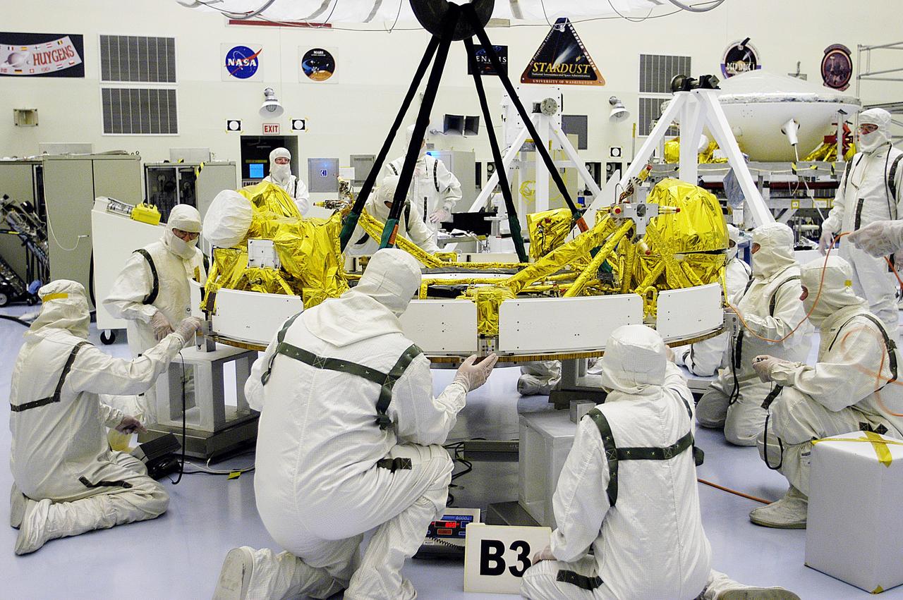
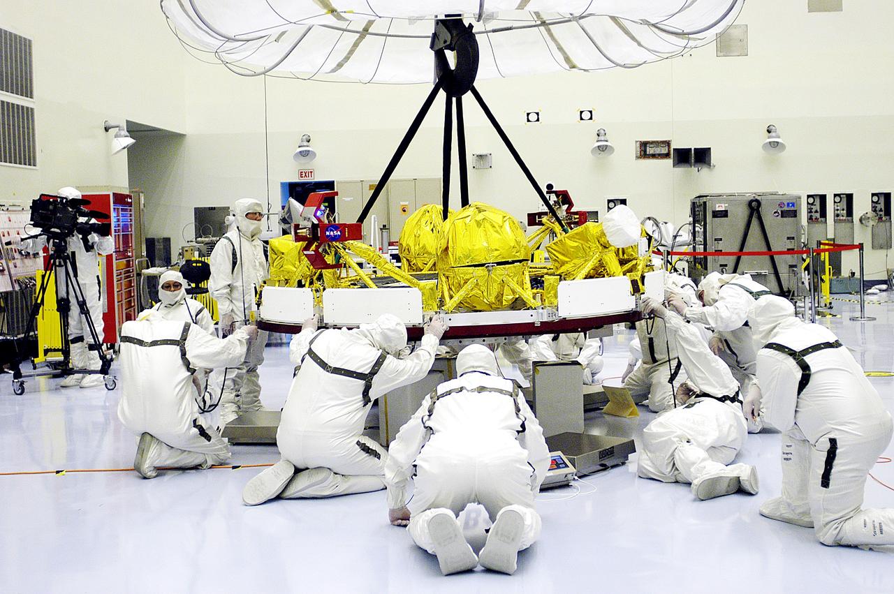
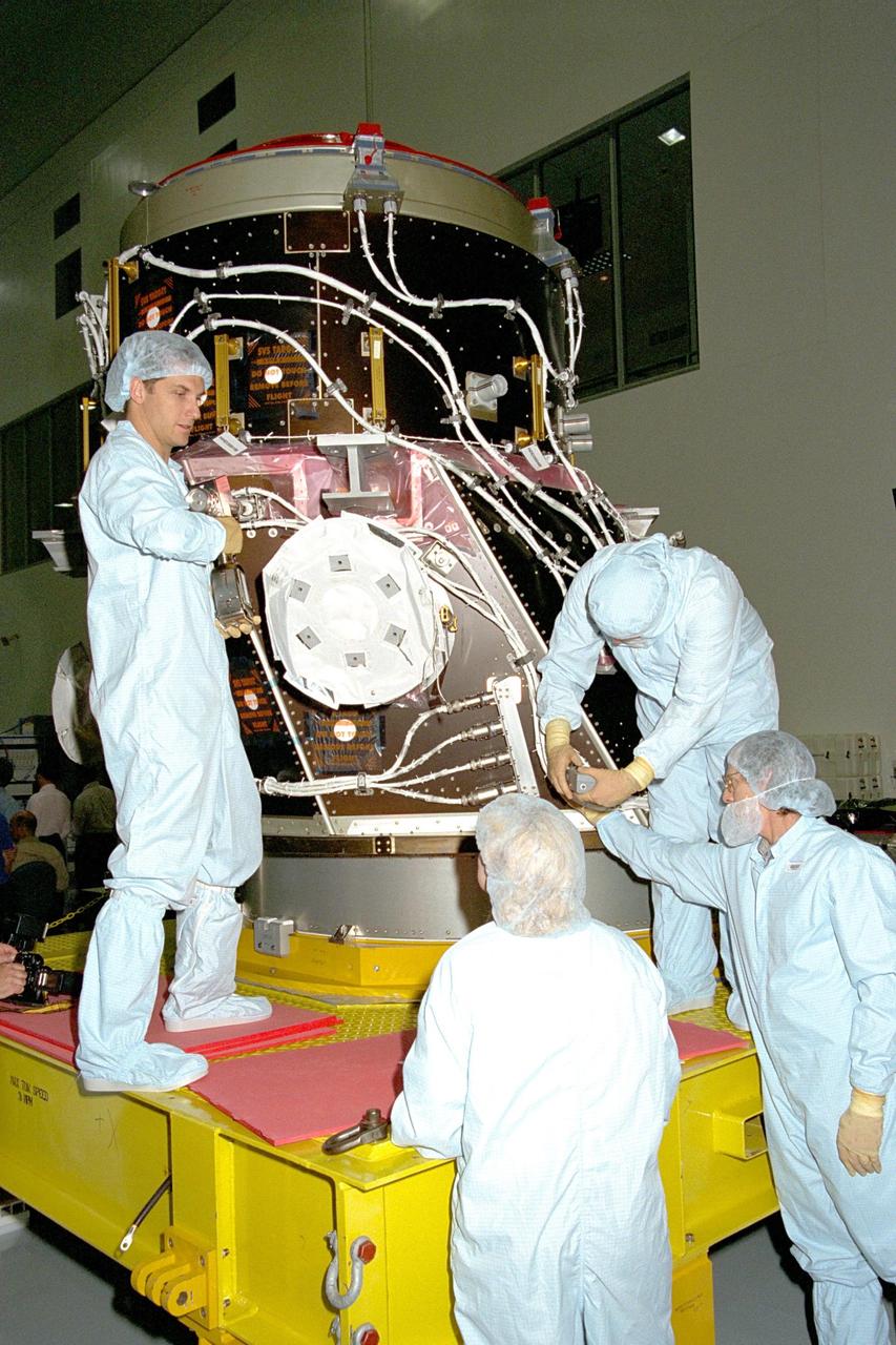
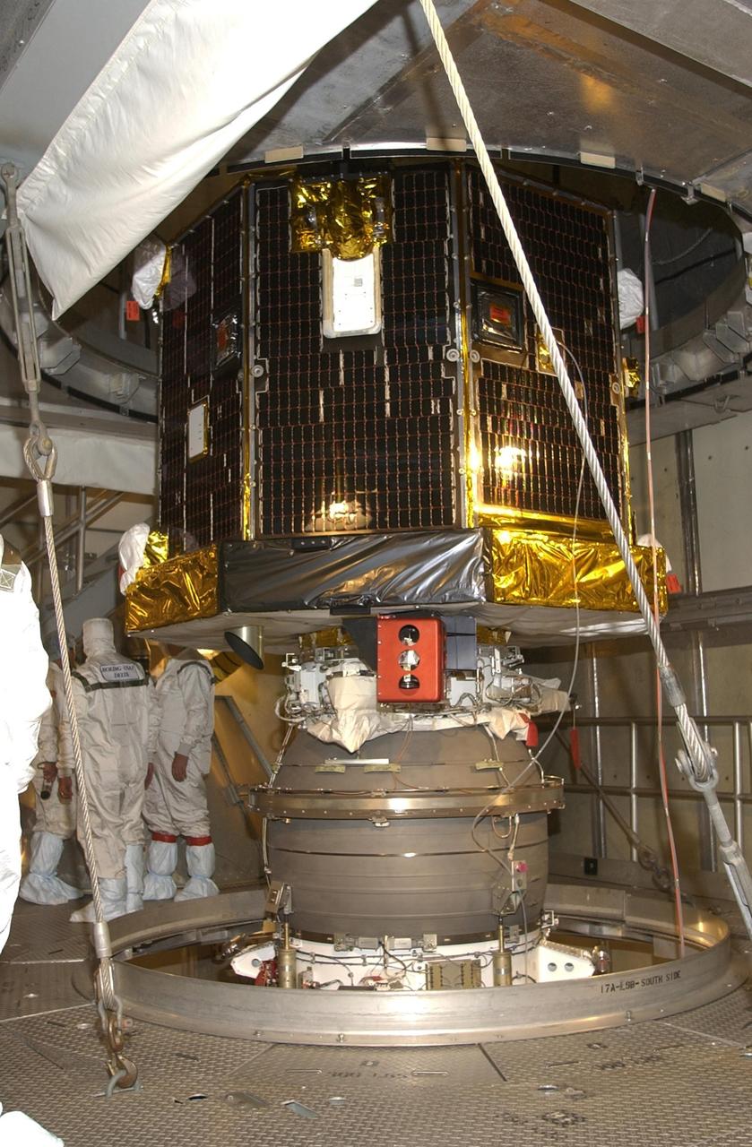
KENNEDY SPACE CENTER, FLA. - In the Payload Hazardous Servicing Facility, workers check the status of the cruise stage of Mars Exploration Rover 1 (MER-1) after being lowered onto blocks. The cruise stage will be integrated with the aeroshell, the entry vehicle. NASA’s twin Mars Exploration Rovers are designed to study the history of water on Mars. These robotic geologists are equipped with a robotic arm, a drilling tool, three spectrometers, and four pairs of cameras that allow them to have a human-like, 3D view of the terrain. Each rover could travel as far as 100 meters in one day to act as Mars scientists' eyes and hands, exploring an environment where humans can’t yet go. The MER-1 is scheduled to launch June 25 from Launch Pad 17-A, Cape Canaveral Air Force Station.
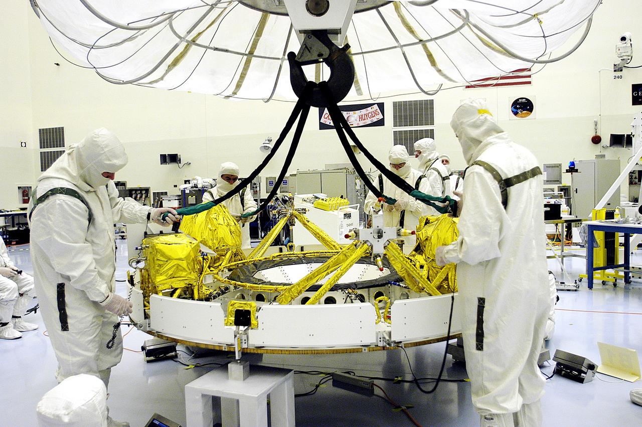
KENNEDY SPACE CENTER, FLA. - In the Payload Hazardous Servicing Facility, workers reattach the tethers of the overhead crane that lowered the cruise stage of Mars Exploration Rover 1 (MER-1) onto blocks. The cruise stage will be lifted and integrated with the aeroshell, the entry vehicle. NASA’s twin Mars Exploration Rovers are designed to study the history of water on Mars. These robotic geologists are equipped with a robotic arm, a drilling tool, three spectrometers, and four pairs of cameras that allow them to have a human-like, 3D view of the terrain. Each rover could travel as far as 100 meters in one day to act as Mars scientists' eyes and hands, exploring an environment where humans can’t yet go. The MER-1 is scheduled to launch June 25 from Launch Pad 17-A, Cape Canaveral Air Force Station.
KENNEDY SPACE CENTER, FLA. - In the Payload Hazardous Servicing Facility, workers help guide the cruise stage of Mars Exploration Rover 1 (MER-1) as it is lowered onto blocks. The cruise stage will be integrated with the aeroshell, the entry vehicle. NASA’s twin Mars Exploration Rovers are designed to study the history of water on Mars. These robotic geologists are equipped with a robotic arm, a drilling tool, three spectrometers, and four pairs of cameras that allow them to have a human-like, 3D view of the terrain. Each rover could travel as far as 100 meters in one day to act as Mars scientists' eyes and hands, exploring an environment where humans can’t yet go. The MER-1 is scheduled to launch June 25 from Launch Pad 17-A, Cape Canaveral Air Force Station.
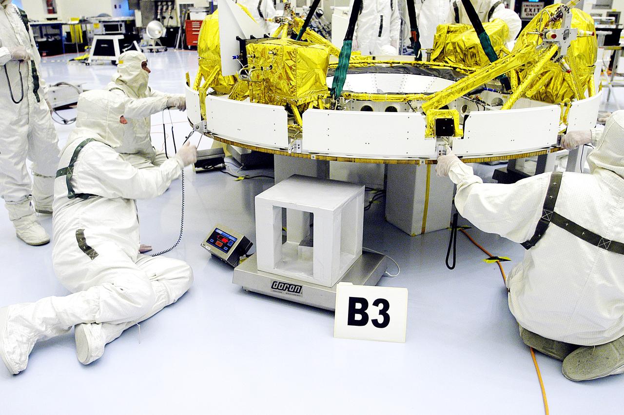
KENNEDY SPACE CENTER, FLA. - In the Payload Hazardous Servicing Facility, workers check the status of the cruise stage of Mars Exploration Rover 1 (MER-1) after being lowered onto blocks. The cruise stage will be integrated with the aeroshell, the entry vehicle. NASA’s twin Mars Exploration Rovers are designed to study the history of water on Mars. These robotic geologists are equipped with a robotic arm, a drilling tool, three spectrometers, and four pairs of cameras that allow them to have a human-like, 3D view of the terrain. Each rover could travel as far as 100 meters in one day to act as Mars scientists' eyes and hands, exploring an environment where humans can’t yet go. The MER-1 is scheduled to launch June 25 from Launch Pad 17-A, Cape Canaveral Air Force Station.
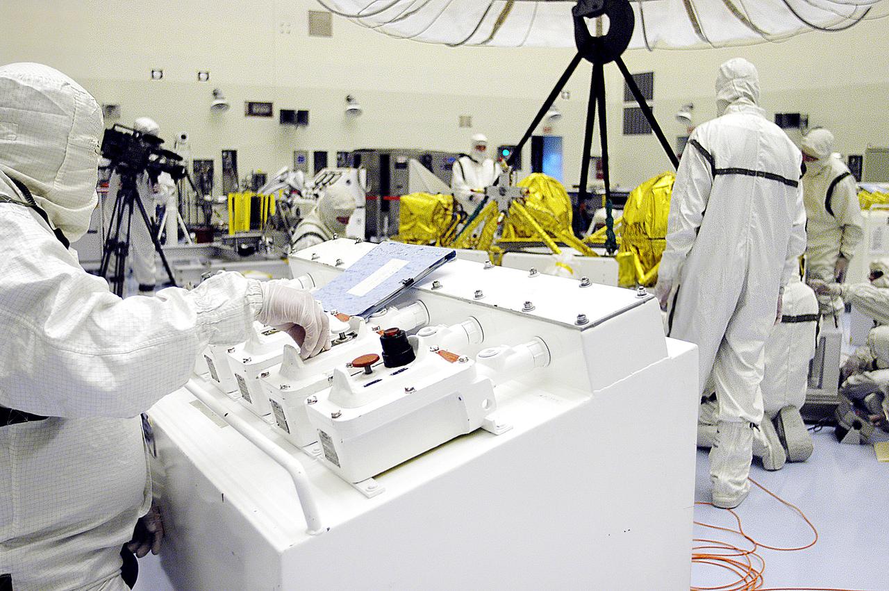
KENNEDY SPACE CENTER, FLA. - In the Payload Hazardous Servicing Facility, workers help guide the cruise stage of Mars Exploration Rover 1 (MER-1) as it is lowered onto blocks. The cruise stage will be integrated with the aeroshell, the entry vehicle. NASA’s twin Mars Exploration Rovers are designed to study the history of water on Mars. These robotic geologists are equipped with a robotic arm, a drilling tool, three spectrometers, and four pairs of cameras that allow them to have a human-like, 3D view of the terrain. Each rover could travel as far as 100 meters in one day to act as Mars scientists' eyes and hands, exploring an environment where humans can’t yet go. The MER-1 is scheduled to launch June 25 from Launch Pad 17-A, Cape Canaveral Air Force Station.
KENNEDY SPACE CENTER, FLA. -- The Pressurized Mating Adapter-1 (PMA-1), scheduled to fly on Space Shuttle mission STS-88 is undergoing processing in the Space Station Processing Facility (SSPF). A PMA is a cone-shaped connector that will be attached to Node 1, the space station’s structural building block, during ground processing. STS-88 is the first International Space Station assembly flight.
KENNEDY SPACE CENTER, FLA. -- The Pressurized Mating Adapter-1 (PMA-1), scheduled to fly on Space Shuttle mission STS-88 is undergoing processing in the Space Station Processing Facility (SSPF). A PMA is a cone-shaped connector that will be attached to Node 1, the space station’s structural building block, during ground processing. STS-88 is the first International Space Station assembly flight.
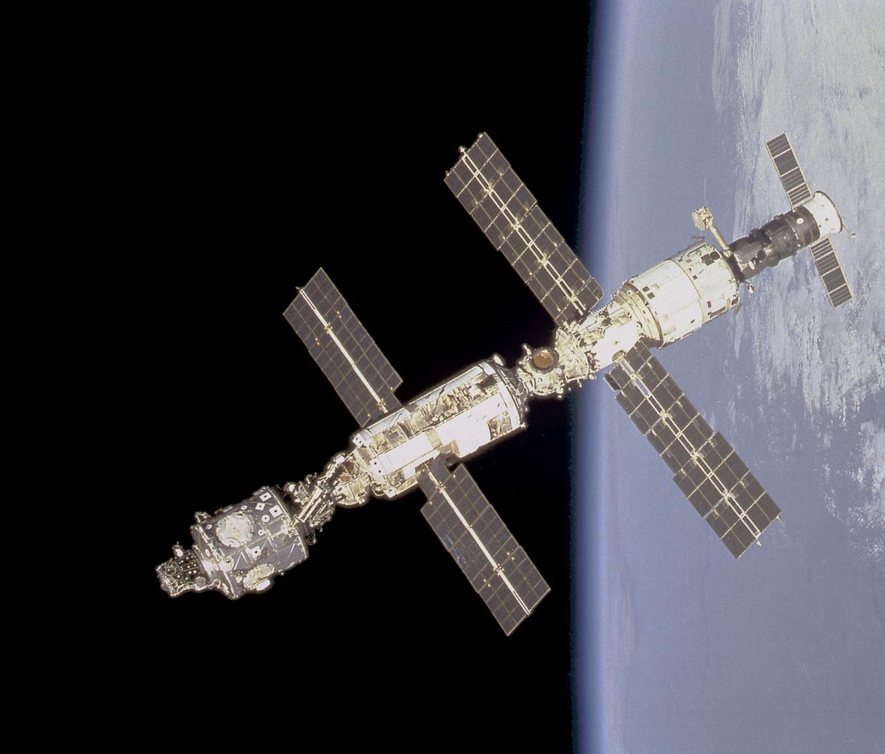
This image of the International Space Station in orbit was taken from the Space Shuttle Endeavour prior to docking. Most of the Station's components are clearly visible in this photograph. They are the Node 1 or Unity Module docked with the Functional Cargo Block or Zarya (top) that is linked to the Zvezda Service Module. The Soyuz spacecraft is at the bottom.
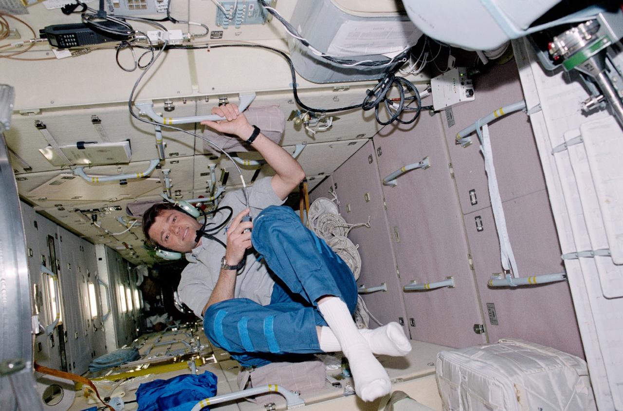
STS100-345-015 (19 April-1 May 2001) --- Astronaut Jeffrey S. Ashby, STS-100 pilot, talks to amateur radio operators on the ground from a special work station on the functional cargo block (FGB) or Zarya module of the International Space Station (ISS).
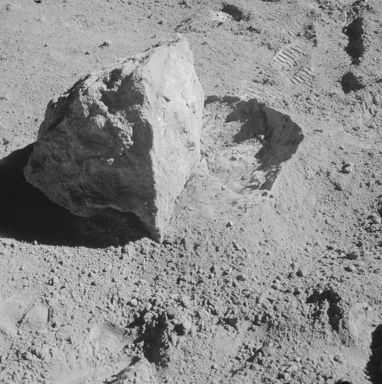
AS16-107-17573 (22 April 1972) --- A close-up view of a block (about 1/2 meter long) found by the two moon-exploring crewmembers of the Apollo 16 lunar landing mission. The block had been rolled over only moments earlier during this Apollo 16 second extravehicular activity (EVA) near South Ray Crater. Astronaut John W. Young, commander, said at the post-mission press conference, "The block has been sitting there evidently since South Ray Crater was formed." While astronauts Young and Charles M. Duke Jr., lunar module pilot; descended in the Apollo 16 Lunar Module (LM) "Orion" to explore the Descartes highlands landing site on the moon, astronaut Thomas K. Mattingly II, command module pilot, remained with the Command and Service Modules (CSM) "Casper" in lunar orbit.
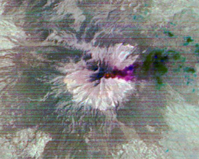
Popocatepetl, Mexico's most active volcano, erupted on February 23, sending blocks and bombs down the volcano's flanks, and emitting an ash column 1 km above the summit. Two days later, an ash cloud was still seen coming from the volcano. The thermal infrared color composite reveals a hot spot (red) at the summit crater. The dark red color near the vent of the east-blowing ash cloud suggests that its composition is dominantly ash material; further downwind, the color changes to purple, suggesting that some of the ash particles may be ice-covered. The images were acquired February 25, 2020, cover an area of 18 by 22.5 km, and are located at 19 degrees north, 98.6 degrees west. https://photojournal.jpl.nasa.gov/catalog/PIA23680
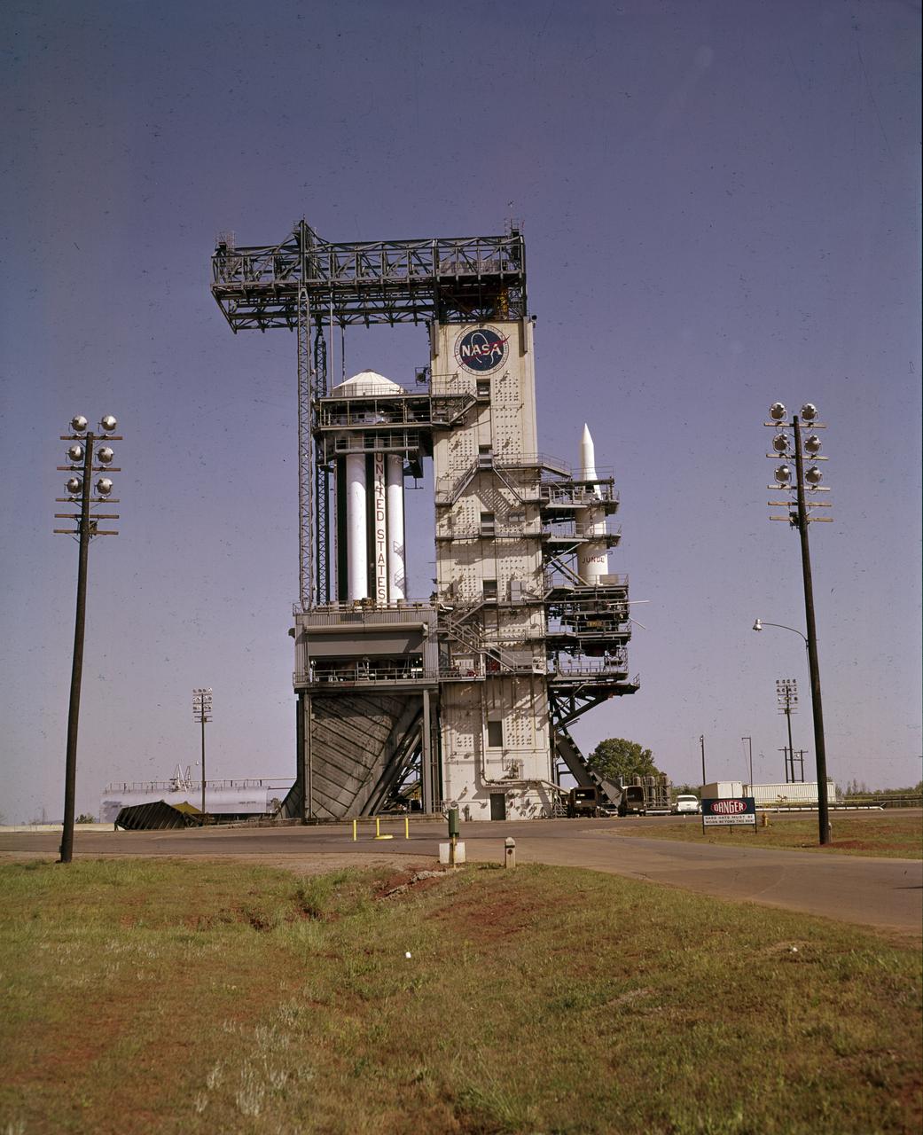
On October 27, 1961, the Marshall Space Flight Center (MSFC) and the Nation marked a high point in the 3-year-old Saturn development program when the first Saturn vehicle flew a flawless 215-mile ballistic trajectory from Cape Canaveral, Florida. SA-1 is pictured here, five months before launch, in the MSFC test stand on May 16, 1961. Developed and tested at MSFC under the direction of Dr. Wernher von Braun, SA-1 incorporated a Saturn I, Block I engine. The typical height of a Block I vehicle was approximately 163 feet. and had only one live stage. It consisted of eight tanks, each 70 inches in diameter, clustered around a central tank, 105 inches in diameter. Four of the external tanks were fuel tanks for the RP-1 (kerosene) fuel. The other four, spaced alternately with the fuel tanks, were liquid oxygen tanks, as was the large center tank. All fuel tanks and liquid oxygen tanks drained at the same rates respectively. The thrust for the stage came from eight H-1 engines, each producing a thrust of 165,000 pounds, for a total thrust of over 1,300,000 pounds. The engines were arranged in a double pattern. Four engines, located inboard, were fixed in a square pattern around the stage axis and canted outward slightly, while the remaining four engines were located outboard in a larger square pattern offset 40 degrees from the inner pattern. Unlike the inner engines, each outer engine was gimbaled. That is, each could be swung through an arc. They were gimbaled as a means of steering the rocket, by letting the instrumentation of the rocket correct any deviations of its powered trajectory. The block I required engine gimabling as the only method of guiding and stabilizing the rocket through the lower atmosphere. The upper stages of the Block I rocket reflected the three-stage configuration of the Saturn I vehicle.
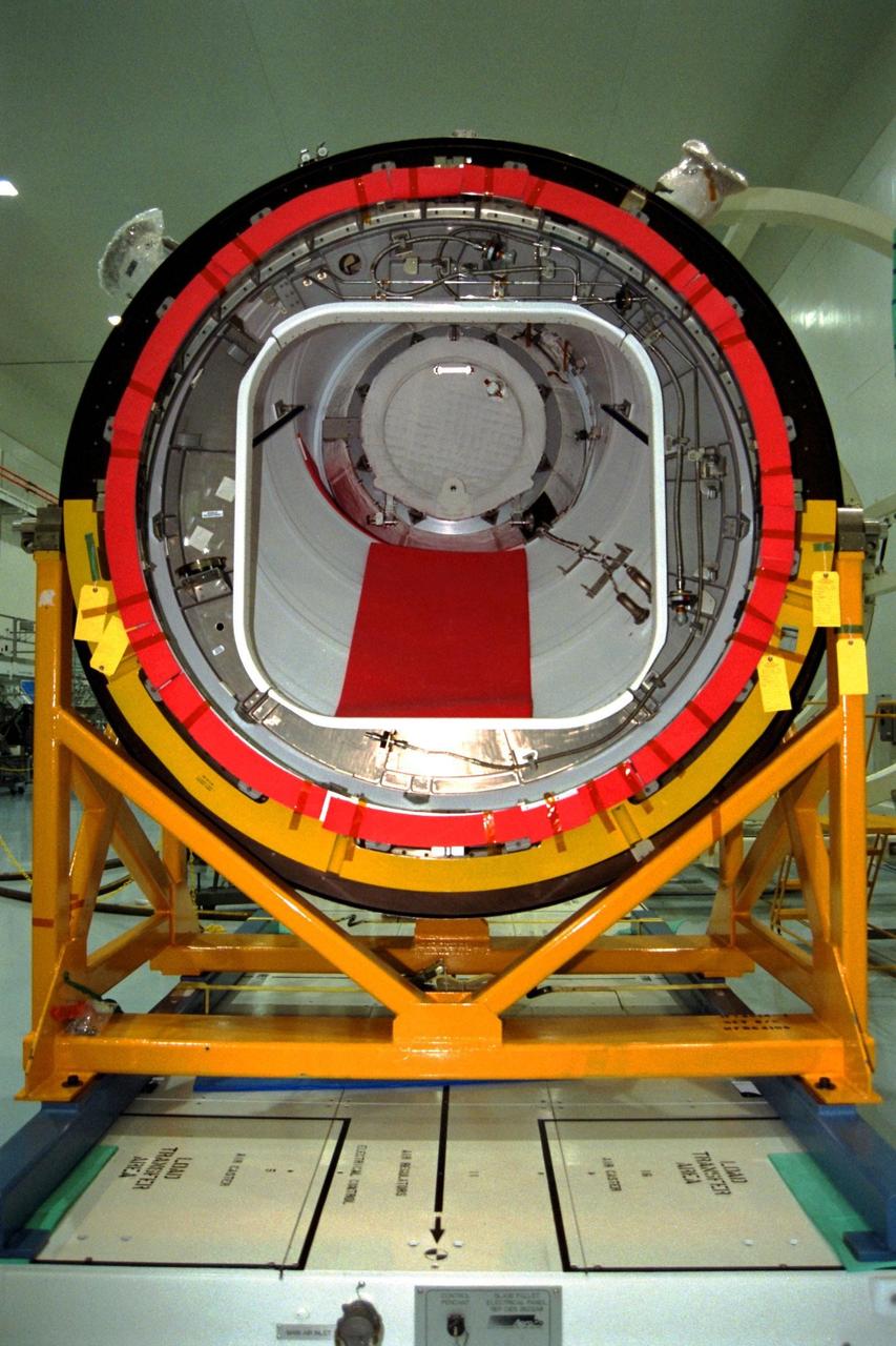
KENNEDY SPACE CENTER, FLA. -- The Pressurized Mating Adapter (PMA)-2 for the International Space Station (ISS) awaits being mated with Node 1, the space station’s structural building block, in KSC’s Space Station Processing Facility. This PMA, identifiable by its bright red ring, is a cone-shaped connector to Node 1, which will have two PMAs attached once this mate is completed. The node and PMAs, which together will make up the first element of the ISS, are scheduled to be launched aboard the Space Shuttle Endeavour on STS-88

KENNEDY SPACE CENTER, FLA. -- The Pressurized Mating Adapter (PMA)-2 for the International Space Station (ISS) is moved on an air pallet toward Node 1, the space station’s structural building block, in KSC’s Space Station Processing Facility. This PMA is a cone-shaped connector to Node 1, which will have two PMAs attached once PMA-2 is mated with the node. The node and PMAs, which together will make up the first element of the ISS, are scheduled to be launched aboard the Space Shuttle Endeavour on STS-88
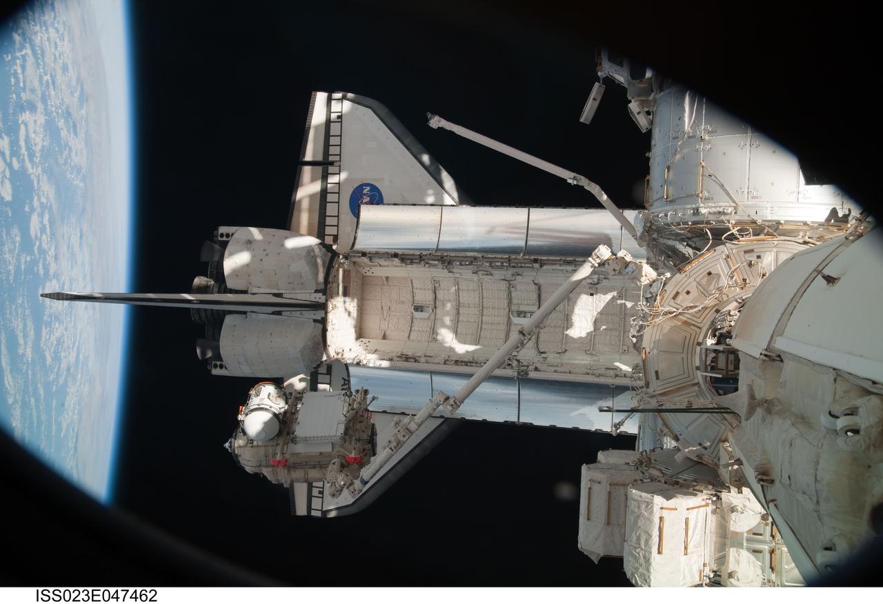
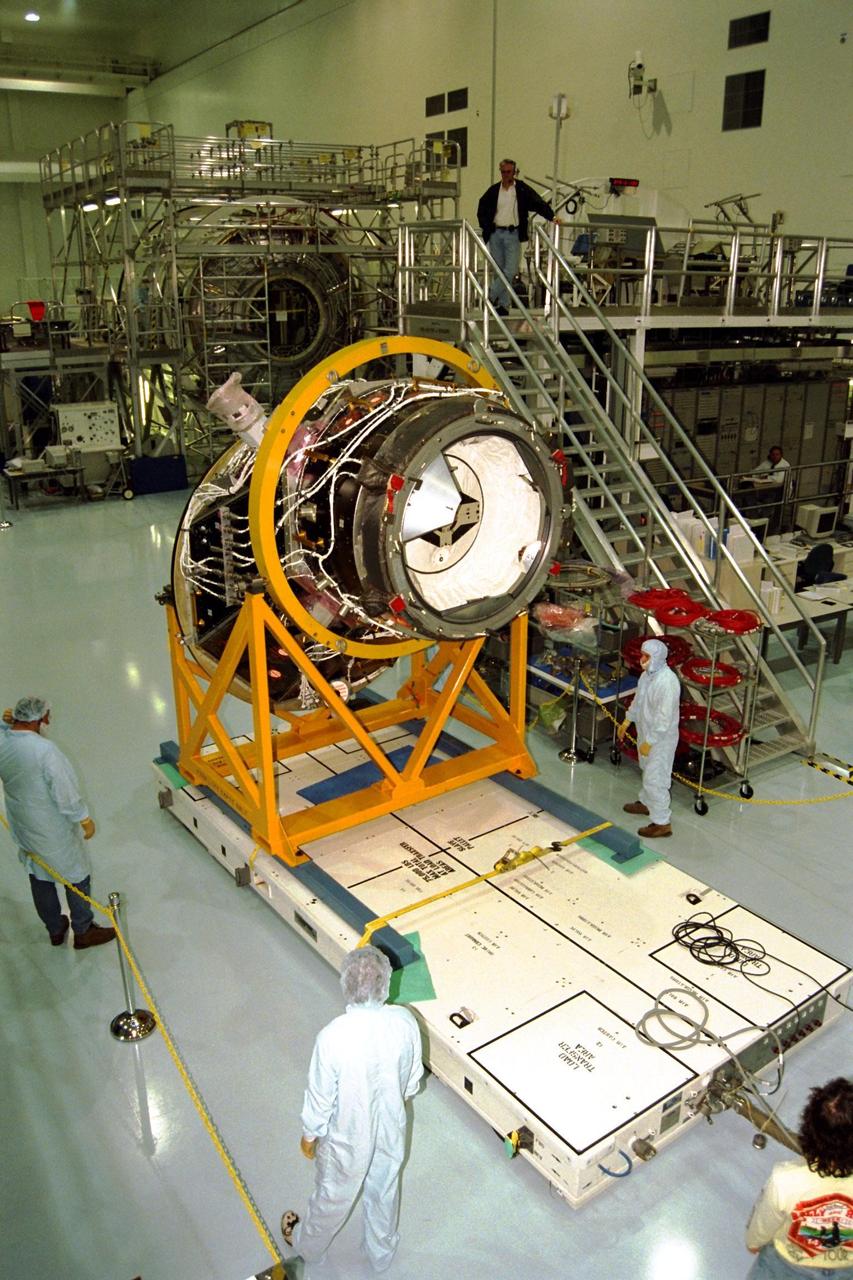
ISS023-E-047462 (18 May 2010) --- In the grasp of the station?s robotic Canadarm2, the Russian-built Mini-Research Module 1 (MRM-1) is moved to be permanently attached to the Earth-facing port of the Zarya Functional Cargo Block (FGB) of the International Space Station. Named Rassvet, Russian for "dawn," the module is the second in a series of new pressurized components for Russia. Rassvet will be used for cargo storage and will provide an additional docking port to the station.
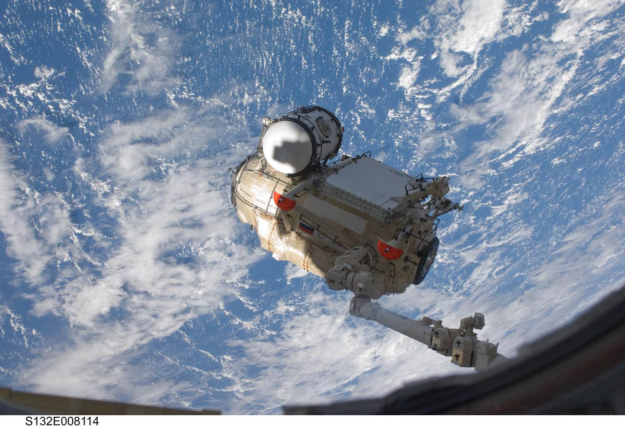
S132-E-008114 (18 May 2010) --- In the grasp of the Canadarm2, the Russian-built Mini-Research Module 1 (MRM-1) is transferred from space shuttle Atlantis’ payload bay to be permanently attached to the Earth-facing port of the Zarya Functional Cargo Block (FGB) of the International Space Station. Named Rassvet, Russian for "dawn," the module is the second in a series of new pressurized components for Russia. Rassvet will be used for cargo storage and will provide an additional docking port to the station.
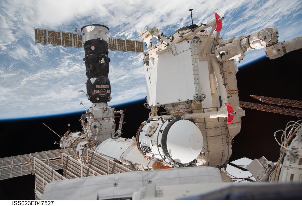
ISS023-E-047527 (18 May 2010) --- In the grasp of the station?s robotic Canadarm2, the Russian-built Mini-Research Module 1 (MRM-1) is attached to the Earth-facing port of the Zarya Functional Cargo Block (FGB) of the International Space Station. Named Rassvet, Russian for "dawn," the module is the second in a series of new pressurized components for Russia. Rassvet will be used for cargo storage and will provide an additional docking port to the station.
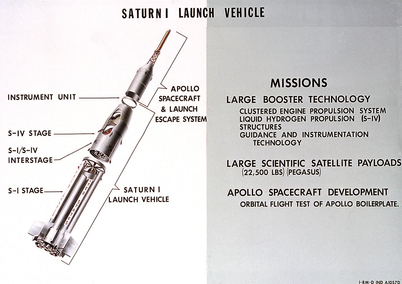
A cutaway illustration of Saturn 1 launch vehicle mission. The Saturn I, first of the Saturn launch vehicles' family, is a two-stage vehicle with a low-earth-orbit payload capability of approximately 25,000 pounds. The research and development program was plarned in two phases or blocks; one for first stage development (Block I) and the second for first and second stage development (Block II). The S-I (first) stage consisted of a cluster of nine propellant tanks and eight H-1 engines built by Rocketdyne, yeilding a total thrust of 1,500,000 pounds. The second stage of Saturn I, identified as S-IV, was designed as a single cylinder with a common bulkhead separating the liquid oxygen from the liquid hydrogen. Propulsion was provided by six RL-10 engines built by Pratt Whitney, capable of producing a combined thrust of 90,000 pounds. Of the 10 Saturn I's planned, the first eight were designed and built at the Marshall Space Flight Center. The remaining two were built by the Chrysler Corporation.
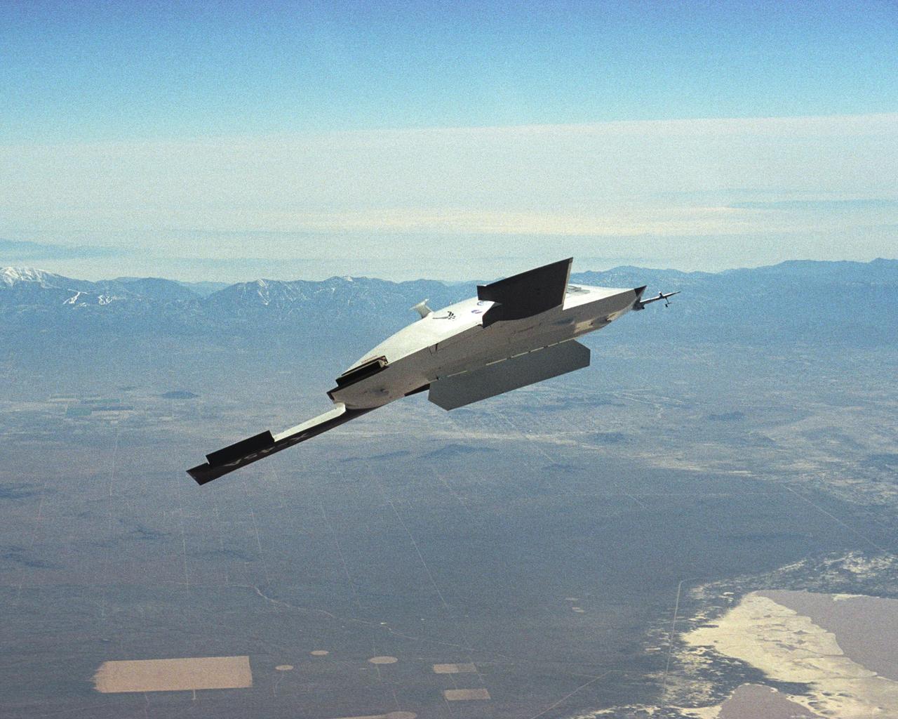
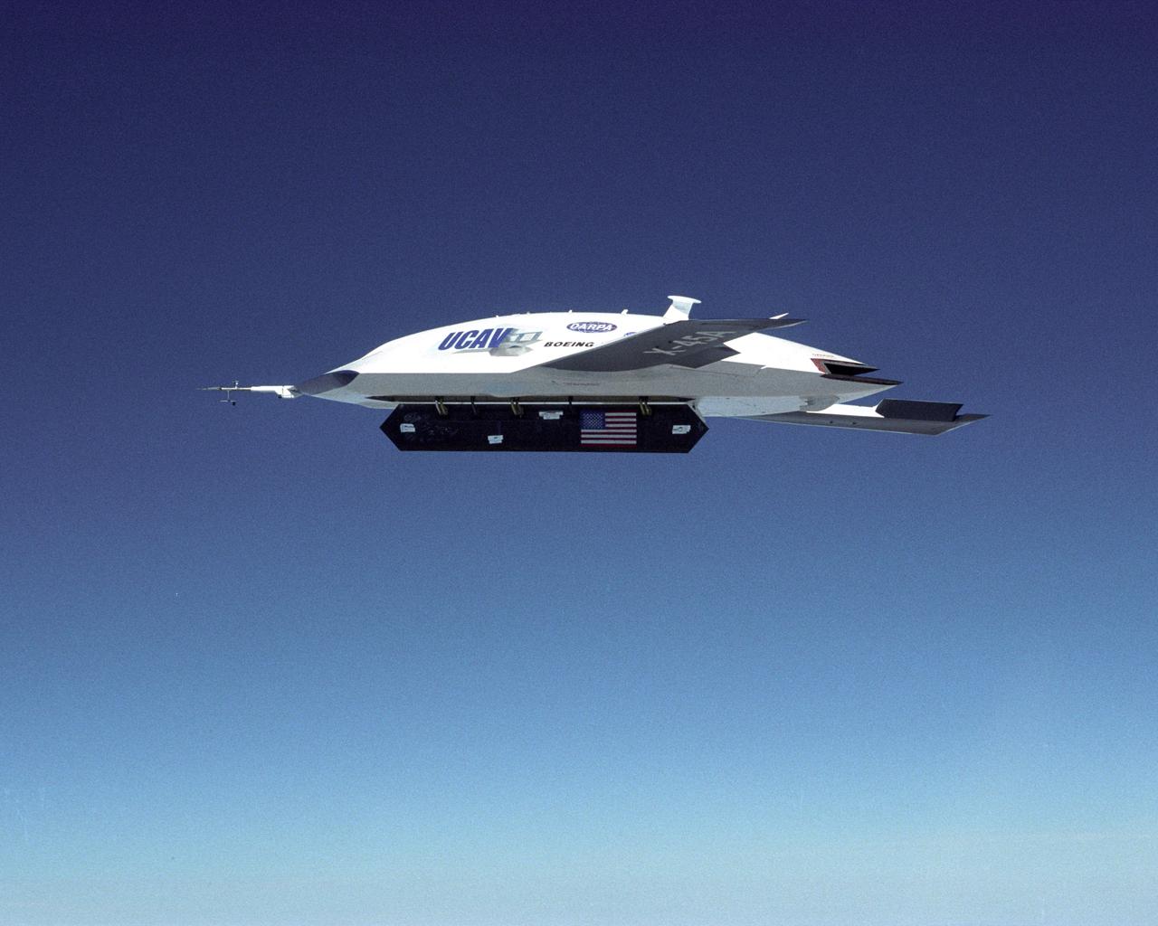
The DARPA/U.S. Air Force X-45A Unmanned Combat Air Vehicle (UCAV) system demonstration program completed the first phase of demonstrations, known as Block I, on Feb. 28, 2003. The final Block I activities included two flights at Dryden, during which safe operation of the weapons bay door was verified at 35,000 feet and speeds of Mach 0.75, the maximum planned altitude and speed for the two X-45A demonstrator vehicles.
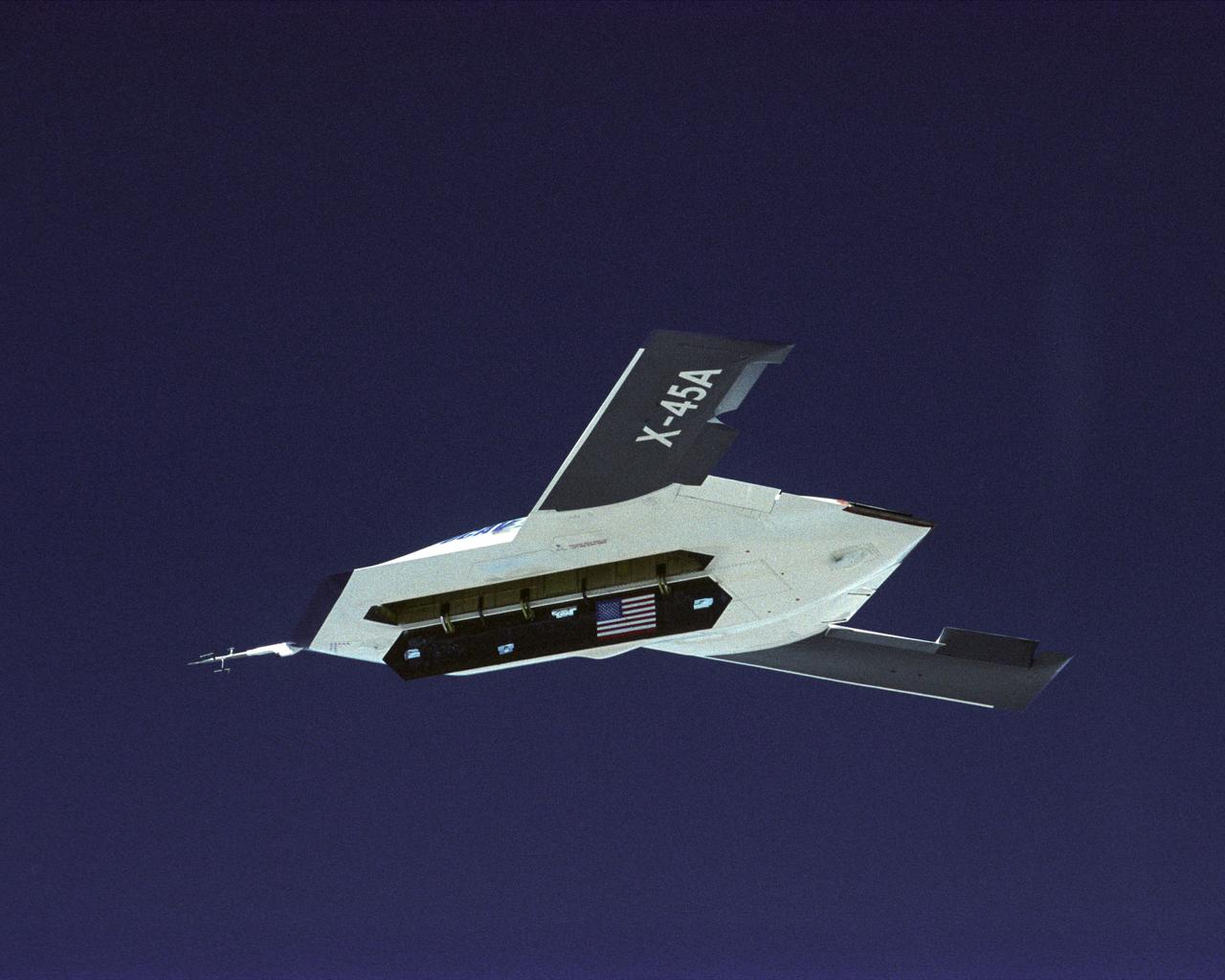
The DARPA/U.S. Air Force X-45A Unmanned Combat Air Vehicle (UCAV) system demonstration program completed the first phase of demonstrations, known as Block I, on Feb. 28, 2003. The final Block I activities included two flights at Dryden, during which safe operation of the weapons bay door was verified at 35,000 feet and speeds of Mach 0.75, the maximum planned altitude and speed for the two X-45A demonstrator vehicles.
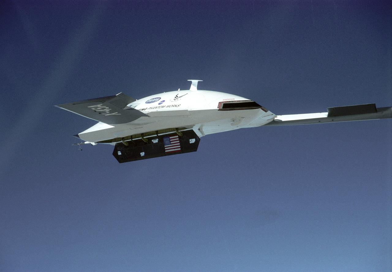
The DARPA/U.S. Air Force X-45A Unmanned Combat Air Vehicle (UCAV) system demonstration program completed the first phase of demonstrations, known as Block I, on Feb. 28, 2003. The final Block I activities included two flights at Dryden, during which safe operation of the weapons bay door was verified at 35,000 feet and speeds of Mach 0.75, the maximum planned altitude and speed for the two X-45A demonstrator vehicles.
The DARPA/U.S. Air Force X-45A Unmanned Combat Air Vehicle (UCAV) system demonstration program completed the first phase of demonstrations, known as Block I, on Feb. 28, 2003. The final Block I activities included two flights at Dryden, during which safe operation of the weapons bay door was verified at 35,000 feet and speeds of Mach 0.75, the maximum planned altitude and speed for the two X-45A demonstrator vehicles.
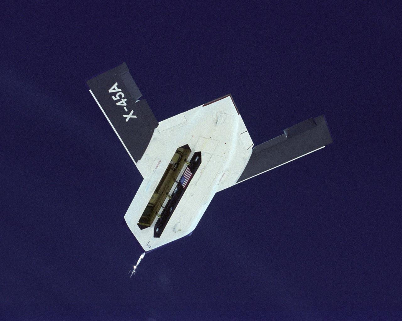
The DARPA/U.S. Air Force X-45A Unmanned Combat Air Vehicle (UCAV) system demonstration program completed the first phase of demonstrations, known as Block I, on Feb. 28, 2003. The final Block I activities included two flights at Dryden, during which safe operation of the weapons bay door was verified at 35,000 feet and speeds of Mach 0.75, the maximum planned altitude and speed for the two X-45A demonstrator vehicles.
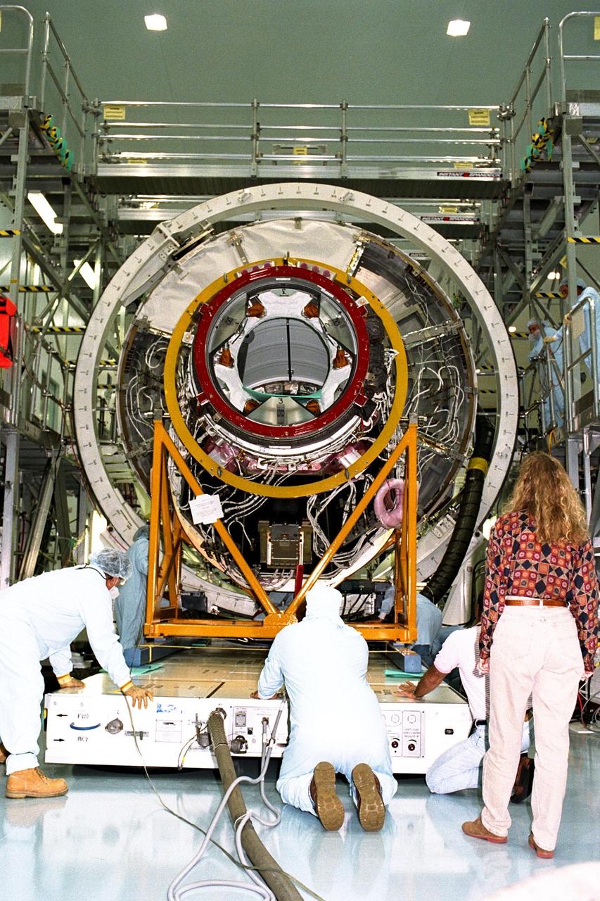
KENNEDY SPACE CENTER, FLA. -- Boeing technicians join Node 1 for the International Space Station (ISS) with the Pressurized Mating Adapter (PMA)-1 in KSC’s Space Station Processing Facility. This PMA, identifiable by its bright red ring, is a cone-shaped connector for the space station’s structural building block, known as Node 1. Seen here surrounded by scaffolding, Node 1 will have two PMAs attached, the second of which is scheduled for mating to the node in January 1998. The node and PMAs, which will be the first element of the ISS, are scheduled to be launched aboard the Space Shuttle Endeavour on STS-88 in July 1998
KENNEDY SPACE CENTER, FLA. -- Boeing technicians join Node 1 for the International Space Station (ISS) with the Pressurized Mating Adapter (PMA)-1 in KSC’s Space Station Processing Facility. This PMA, identifiable by its bright red ring, is a cone-shaped connector for the space station’s structural building block, known as Node 1. Seen here surrounded by scaffolding, Node 1 will have two PMAs attached, the second of which is scheduled for mating to the node in January 1998. The node and PMAs, which will be the first element of the ISS, are scheduled to be launched aboard the Space Shuttle Endeavour on STS-88 in July 1998
The Saturn I (SA-4) flight lifted off from Kennedy Space Center launch Complex 34, March 28, 1963. The fourth launch of Saturn launch vehicles developed at the Marshall Space Flight Center (MSFC), under the direction of Dr. Wernher von Braun, incorporated a Saturn I, Block I engine. The typical height of a Block I vehicle was approximately 163 feet and had only one live stage. It consisted of eight tanks, each 70 inches in diameter, clustered around a central tank, 105 inches in diameter. Four of the external tanks were fuel tanks for the RP-1 (kerosene) fuel. The other four, spaced alternately with the fuel tanks, were liquid oxygen tanks as was the large center tank. All fuel tanks and liquid oxygen tanks drained at the same rates respectively. The thrust for the stage came from eight H-1 engines, each producing a thrust of 165,000 pounds, for a total thrust of over 1,300,000 pounds. The engines were arranged in a double pattern. Four engines, located inboard, were fixed in a square pattern around the stage axis and canted outward slightly, while the remaining four engines were located outboard in a larger square pattern offset 40 degrees from the inner pattern. Unlike the inner engines, each outer engine was gimbaled. That is, each could be swung through an arc. They were gimbaled as a means of steering the rocket, by letting the instrumentation of the rocket correct any deviations of its powered trajectory. The block I required engine gimabling as the only method of guiding and stabilizing the rocket through the lower atmosphere. The upper stages of the Block I rocket reflected the three-stage configuration of the Saturn I vehicle. Like SA-3, the SA-4 flight’s upper stage ejected 113,560 liters (30,000 gallons) of ballast water in the upper atmosphere for "Project Highwater" physics experiment. Release of this vast quantity of water in a near-space environment marked the second purely scientific large-scale experiment. The SA-4 was the last Block I rocket launch.
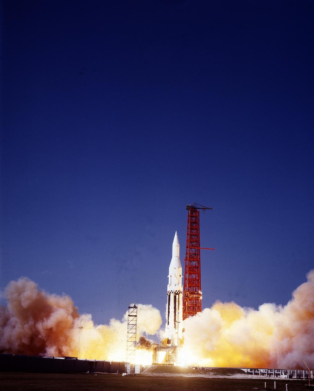
The Saturn I (SA-4) flight lifted off from Kennedy Space Center launch Complex 34, March 28, 1963. The fourth launch of Saturn launch vehicles, developed at the Marshall Space Flight Center (MSFC) under the direction of Dr. Wernher von Braun, incorporated a Saturn I, Block I engine. The typical height of a Block I vehicle was approximately 163 feet and had only one live stage. It consisted of eight tanks, each 70 inches in diameter, clustered around a central tank, 105 inches in diameter. Four of the external tanks were fuel tanks for the RP-1 (kerosene) fuel. The other four, spaced alternately with the fuel tanks, were liquid oxygen tanks as was the large center tank. All fuel tanks and liquid oxygen tanks drained at the same rates respectively. The thrust for the stage came from eight H-1 engines, each producing a thrust of 165,000 pounds, for a total thrust of over 1,300,000 pounds. The engines were arranged in a double pattern. Four engines, located inboard, were fixed in a square pattern around the stage axis and canted outward slightly, while the remaining four engines were located outboard in a larger square pattern offset 40 degrees from the inner pattern. Unlike the inner engines, each outer engine was gimbaled. That is, each could be swung through an arc. They were gimbaled as a means of steering the rocket, by letting the instrumentation of the rocket correct any deviations of its powered trajectory. The block I required engine gimabling as the only method of guiding and stabilizing the rocket through the lower atmosphere. The upper stages of the Block I rocket reflected the three-stage configuration of the Saturn I vehicle. Like SA-3, the SA-4 flight’s upper stage ejected 113,560 liters (30,000 gallons) of ballast water in the upper atmosphere for "Project Highwater" physics experiment. Release of this vast quantity of water in a near-space environment marked the second purely scientific large-scale experiment. The SA-4 was the last Block I rocket launch.
KENNEDY SPACE CENTER, FLA. -- The Pressurized Mating Adapter (PMA)-2, seen here in its yellow workstand, is moved on an air pallet toward Node 1, the International Space Station’s (ISS's) structural building block, in KSC’s Space Station Processing Facility. This PMA is a cone-shaped connector to Node 1, which will have two PMAs attached once PMA-2 is mated with the node. Node 1 can be seen directly behind PMA-2. The node and PMAs, which together will make up the first element of the ISS, are scheduled to be launched aboard the Space Shuttle Endeavour on STS-88.
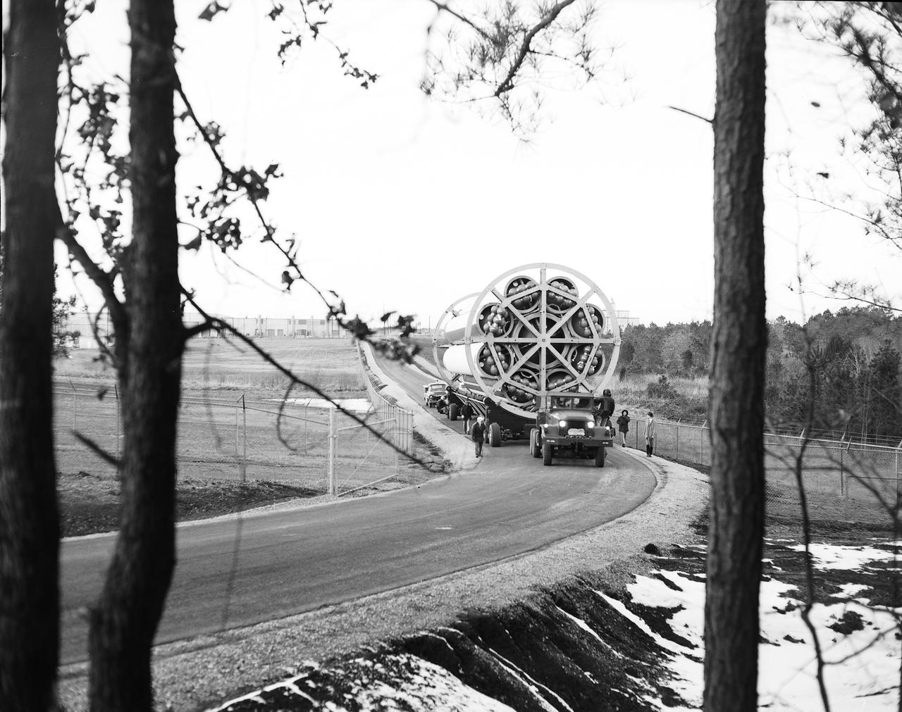
This photograph shows the Saturn-I first stage (S-1 stage) being transported to the test stand for a static test firing at the Marshall Space Flight Center. Soon after NASA began operations in October 1958, it was evident that sending people and substantial equipment beyond the Earth's gravitational field would require launch vehicles with weight-lifting capabilities far beyond any developed to that time. In early 1959, NASA accepted the proposal of Dr. Wernher von Braun for a multistage rocket, with a number of engines clustered in one or more of the stages to provide a large total thrust. The initiation of the Saturn launch vehicle program ultimately led to the study and preliminary plarning of many different configurations and resulted in production of three Saturn launch vehicles, the Saturn-I, Saturn I-B, and Saturn V. The Saturn family of launch vehicles began with the Saturn-I, a two-stage vehicle originally designated C-1. The research and development program was planned in two phases, or blocks: one for first stage development (Block I) and the second for both first and second stage development (Block-II). Saturn I had a low-earth-orbit payload capability of approximately 25,000 pounds. The design of the first stage (S-1 stage) used a cluster of propellant tanks containing liquid oxygen (LOX) and kerosene (RP-1), and eight H-1 engines, yielding a total thrust of 1,500,000 pounds. Of the ten Saturn-Is planned, the first eight were designed and built at the Marshall Space Flight Center, and the remaining two were built by the Chrysler Corporation.
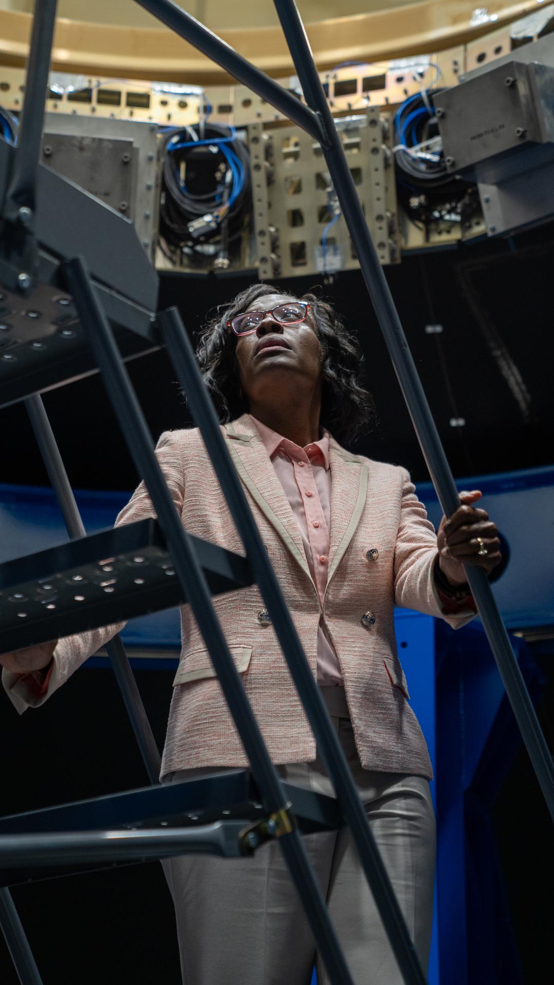
Lakiesha Hawkins, Assistant Deputy Associate Administrator for the Moon to Mars (M2M) Program within the Exploration Systems Development Mission Directorate (ESDMD), takes a peek at the Payload Adapter test article at Marshall Space Flight Center. The adapter, which will debut on NASA’s Artemis IV mission, is an evolution from the Orion stage adapter used in the Block 1 configuration of the rocket for the first three Artemis missions. It will be housed inside the universal stage adapter atop the rocket’s more powerful in-space stage, called the exploration upper stage. The payload adapter, like the launch vehicle stage adapter and the Orion stage adapter, is fully manufactured and tested at Marshall, which manages the SLS Program.
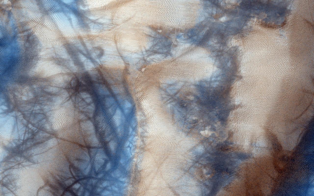
Gully and defrosting activity have been visible here along the edge of a dune field, along with blocks of frost. Observations from NASA Mars Reconnaissance Orbiter of the same area help check for repeat activity, as well as measuring those meter-scale blocks that we've seen prior. In this case, we want to compare any possible changes with a previous observation, which we acquired in 2011. We've also seen images where carbon dioxide frost was the driving process in creating new gullies, so we know their formation is occurring to this day. Tracking for changes, especially when we look at the 1-kilometer enhanced color swath, can help us find more. http://photojournal.jpl.nasa.gov/catalog/PIA19843
KENNEDY SPACE CENTER, FLA. -- The Pressurized Mating Adapter 2 (PMA 2), part of the first International Space Station (ISS) element to be launched from the U.S., awaits prelaunch processing in the Space Station Processing Facility after its arrival at KSC. PMAs 1 and 2 attached to a component called Node 1, a Station structural building block, will make up the first U.S.-launched ISS element. The Node 1/PMA assembly will provide key connecting points in orbit for other Space Station modules and for docking of the orbiter with the ISS. PMA 1 will provide the interface between U.S. and Russian elements of the Station; PMA 2 will provide a Shuttle orbiter docking area. The Node 1/PMA assembly is targeted for liftoff aboard the Space Shuttle Endeavour on STS-88 in July 1998.
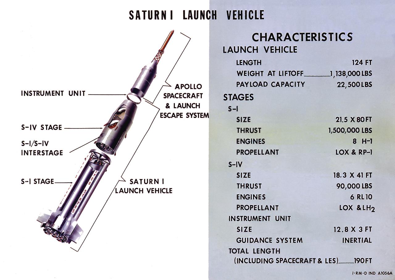
A cutaway illustration of Saturn I launch vehicle characteristics: The Saturn I, first of the Saturn launch vehicles' family, is a two-stage vehicle with a low-earth-orbit payload capability of approximately 25,000 pounds. The research and development program was plarned in two phases or blocks; one for first stage development (Block I) and the second for first and second stage development (Block II). The S-I (first) stage consisted of a cluster of nine propellant tanks and eight H-1 engines built by Rocketdyne, yeilding a total thrust of 1,500,000 pounds. The second stage identified as S-IV, was designed as a single cylinder with a common bulkhead separating the liquid oxygen from the liquid hydrogen. Propulsion was provided by six RL-10 engines built by Pratt Whitney, capable of producing a combined thrust of 90,000 pounds. Of the 10 Saturn I's planned, the first eight were designed and built at the Marshall Space Flight Center. The remaining two were built by the Chrysler Corporation.
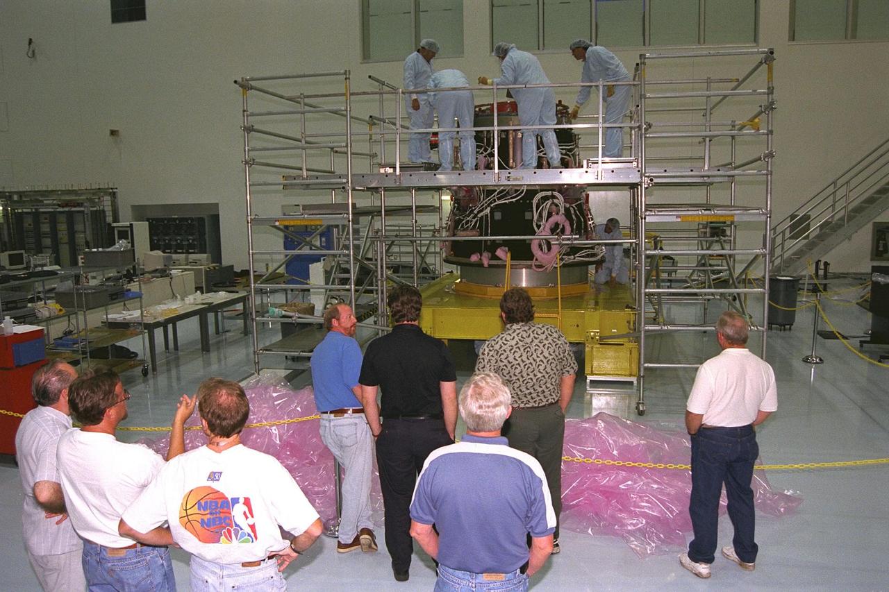
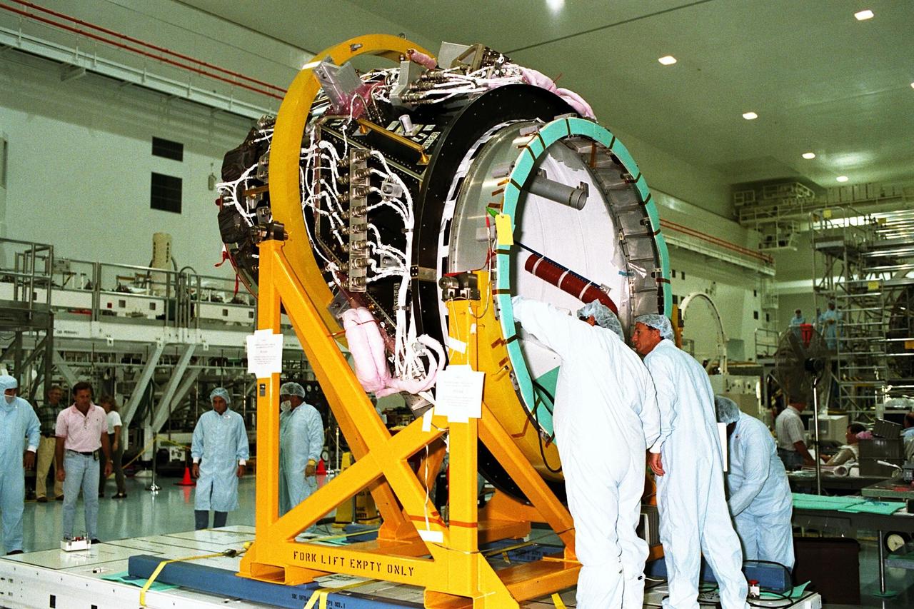
![KENNEDY SPACE CENTER, FLA. -- Technicians and workers observe preparations to join the Pressurized Mating Adapter (PMA)-2, seen here in its yellow workstand at right, to Node 1 (the International Space Station’s [ISS] structural building block) in KSC’s Space Station Processing Facility. This PMA is a cone-shaped connector to Node 1, which will have two PMAs attached once PMA-2 is mated with the node. The node (surrounded here by scaffolding) and PMAs, which together will make up the first element of the ISS, are scheduled to be launched aboard the Space Shuttle Endeavour on STS-88](https://images-assets.nasa.gov/image/KSC-98pc298/KSC-98pc298~medium.jpg)
KENNEDY SPACE CENTER, FLA. -- Technicians and workers observe preparations to join the Pressurized Mating Adapter (PMA)-2, seen here in its yellow workstand at right, to Node 1 (the International Space Station’s [ISS] structural building block) in KSC’s Space Station Processing Facility. This PMA is a cone-shaped connector to Node 1, which will have two PMAs attached once PMA-2 is mated with the node. The node (surrounded here by scaffolding) and PMAs, which together will make up the first element of the ISS, are scheduled to be launched aboard the Space Shuttle Endeavour on STS-88
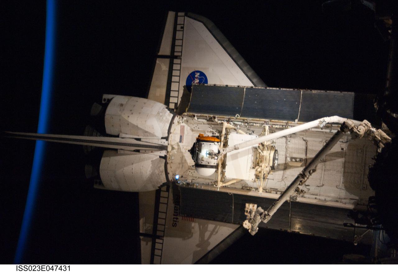
ISS023-E-047431 (18 May 2010) --- Intersecting the thin line of Earth's atmosphere, the docked space shuttle Atlantis is featured in this image photographed by an Expedition 23 crew member on the International Space Station. The Russian-built Mini-Research Module 1 (MRM-1) is visible in the payload bay as the shuttle robotic arm prepares to unberth the module from Atlantis and position it for handoff to the station robotic arm. Named Rassvet, Russian for "dawn," the module is the second in a series of new pressurized components for Russia and will be permanently attached to the Earth-facing port of the Zarya Functional Cargo Block (FGB). Rassvet will be used for cargo storage and will provide an additional docking port to the station.
KENNEDY SPACE CENTER, FLA. -- The Pressurized Mating Adapter (PMA)-2 for the International Space Station (ISS), seen here in its yellow workstand, is moved on an air pallet toward Node 1, the space station’s structural building block, in KSC’s Space Station Processing Facility. This PMA is a cone-shaped connector to Node 1, which will have two PMAs attached once PMA-2 is mated with the node. The node and PMAs, which together will make up the first element of the ISS, are scheduled to be launched aboard the Space Shuttle Endeavour on STS-88
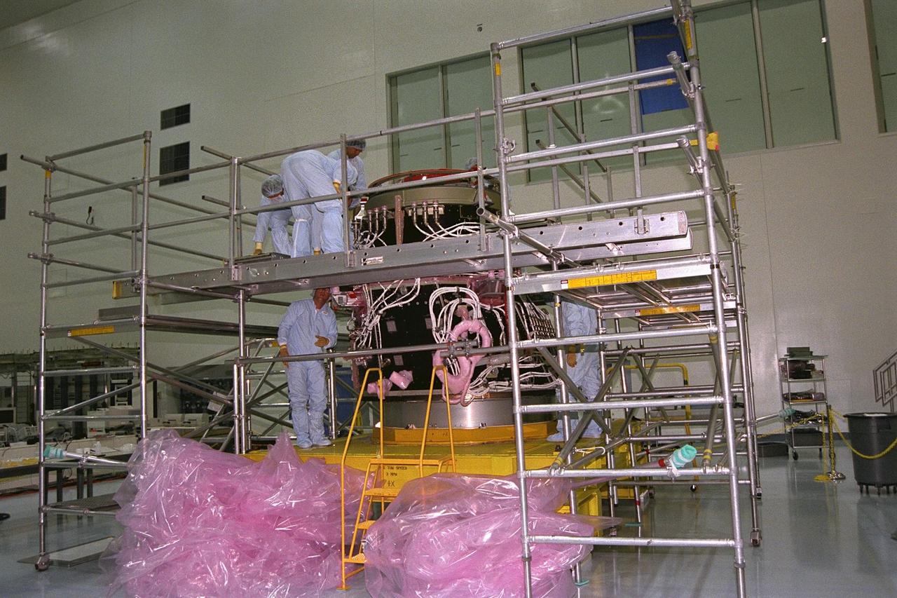
![KENNEDY SPACE CENTER, FLA. -- Technicians prepare to join the Pressurized Mating Adapter (PMA)-2, seen here in its yellow workstand at right, to Node 1 (the International Space Station’s [ISS] structural building block) in KSC’s Space Station Processing Facility. This PMA is a cone-shaped connector to Node 1, which will have two PMAs attached once PMA-2 is mated with the node. The node and PMAs, which together will make up the first element of the ISS, are scheduled to be launched aboard the Space Shuttle Endeavour on STS-88.](https://images-assets.nasa.gov/image/KSC-98pc297/KSC-98pc297~medium.jpg)
KENNEDY SPACE CENTER, FLA. -- Technicians prepare to join the Pressurized Mating Adapter (PMA)-2, seen here in its yellow workstand at right, to Node 1 (the International Space Station’s [ISS] structural building block) in KSC’s Space Station Processing Facility. This PMA is a cone-shaped connector to Node 1, which will have two PMAs attached once PMA-2 is mated with the node. The node and PMAs, which together will make up the first element of the ISS, are scheduled to be launched aboard the Space Shuttle Endeavour on STS-88.
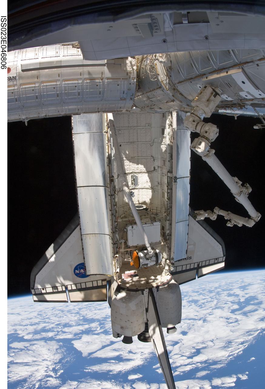
ISS023-E-046806 (18 May 2010) --- Backdropped by Earth?s horizon and the blackness of space, the docked space shuttle Atlantis is featured in this image photographed by an Expedition 23 crew member on the International Space Station. The Russian-built Mini-Research Module 1 (MRM-1) is visible in the payload bay as the shuttle robotic arm prepares to unberth the module from Atlantis and position it for handoff to the station robotic arm (visible at right). Named Rassvet, Russian for "dawn," the module is the second in a series of new pressurized components for Russia and will be permanently attached to the Earth-facing port of the Zarya Functional Cargo Block (FGB). Rassvet will be used for cargo storage and will provide an additional docking port to the station.
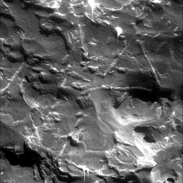
![This scene is a jumbled mess. There are blocks and smears of many different rocks types that appear to have been dumped into a pile. That's probably about what happened, as ejecta from the Isidis impact basin to the east. This pile of old rocks is an island surrounded by younger lava flows from Syrtis Major. The map is projected here at a scale of 25 centimeters (9.8 inches) per pixel. [The original image scale is 27.4 centimeters (10.8 inches) per pixel (with 1 x 1 binning); objects on the order of 82 centimeters (32.2 inches) across are resolved.] North is up. http://photojournal.jpl.nasa.gov/catalog/PIA21553](https://images-assets.nasa.gov/image/PIA21553/PIA21553~medium.jpg)
This scene is a jumbled mess. There are blocks and smears of many different rocks types that appear to have been dumped into a pile. That's probably about what happened, as ejecta from the Isidis impact basin to the east. This pile of old rocks is an island surrounded by younger lava flows from Syrtis Major. The map is projected here at a scale of 25 centimeters (9.8 inches) per pixel. [The original image scale is 27.4 centimeters (10.8 inches) per pixel (with 1 x 1 binning); objects on the order of 82 centimeters (32.2 inches) across are resolved.] North is up. http://photojournal.jpl.nasa.gov/catalog/PIA21553
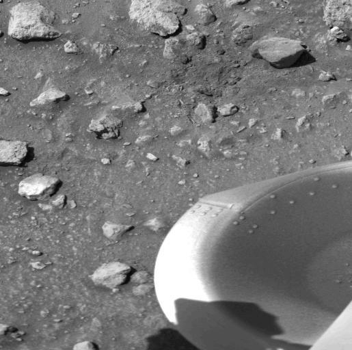
The patch of dark material toward the top of this picture (arrow) taken by NASA's Viking 1 Lander is the debris kicked up by the impact of a protective cover ejected from the spacecraft at 1 a.m. today. The cylindrical cover, which bounced out of view of the camera, protects the scoop at the end of the soil sampler arm. (The scoop will dig into the Martian surface for the first time on July 28). Dust and debris atop the footpad remains as it was seen in the Lander's first picture taken immediately after landing two days ago. No wind modification is apparent. On the surface, a variety of block sizes, shapes and tones are seen, and some rocks are Partially buried. http://photojournal.jpl.nasa.gov/catalog/PIA00384
The Saturn I (SA-3) flight lifted off from Kennedy Space Center launch Complex 34, November 16, 1962. The third launch of Saturn launch vehicles, developed at the Marshall Space Flight Center (MSFC) under the direction of Dr. Wernher von Braun, incorporated a Saturn I, Block I engine. The typical height of a Block I vehicle was approximately 163 feet. and had only one live stage. It consisted of eight tanks, each 70 inches in diameter, clustered around a central tank, 105 inches in diameter. Four of the external tanks were fuel tanks for the RP-1 (kerosene) fuel. The other four, spaced alternately with the fuel tanks, were liquid oxygen tanks as was the large center tank. All fuel tanks and liquid oxygen tanks drained at the same rates respectively. The thrust for the stage came from eight H-1 engines, each producing a thrust of 165,000 pounds, for a total thrust of over 1,300,000 pounds. The engines were arranged in a double pattern. Four engines, located inboard, were fixed in a square pattern around the stage axis and canted outward slightly, while the remaining four engines were located outboard in a larger square pattern offset 40 degrees from the inner pattern. Unlike the inner engines, each outer engine was gimbaled. That is, each could be swung through an arc. They were gimbaled as a means of steering the rocket, by letting the instrumentation of the rocket correct any deviations of its powered trajectory. The block I required engine gimabling as the only method of guiding and stabilizing the rocket through the lower atmosphere. The upper stages of the Block I rocket reflected the three-stage configuration of the Saturn I vehicle. During the SA-3 flight, the upper stage ejected 113,560 liters (30,000 gallons) of ballast water in the upper atmosphere for "Project Highwater" physics experiment. The water was released at an altitude of 65 miles, where within only 5 seconds, it expanded into a massive ice cloud 4.6 miles in diameter. Release of this vast quantity of water in a near-space environment marked the first purely scientific large-scale experiment.
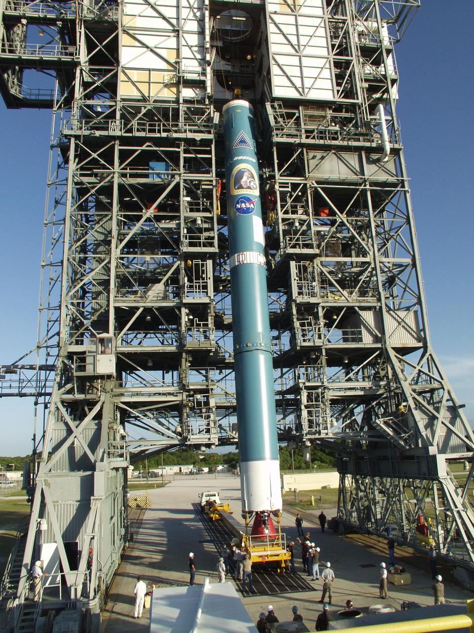
KENNEDY SPACE CENTER, FLA. -- The Boeing Delta II rocket nears a vertical position as it is lifted from the gantry. The rocket is the launch vehicle for the CONTOUR spacecraft, scheduled to launch July 1. CONTOUR will provide the first detailed look into the heart of a comet -- the nucleus. The spacecraft will fly close to at least two comets, Encke and Schwassmann-Wachmann 3, taking pictures of the nucleus while analyzing the gas and dust that surround these rocky, icy building blocks of the solar system.
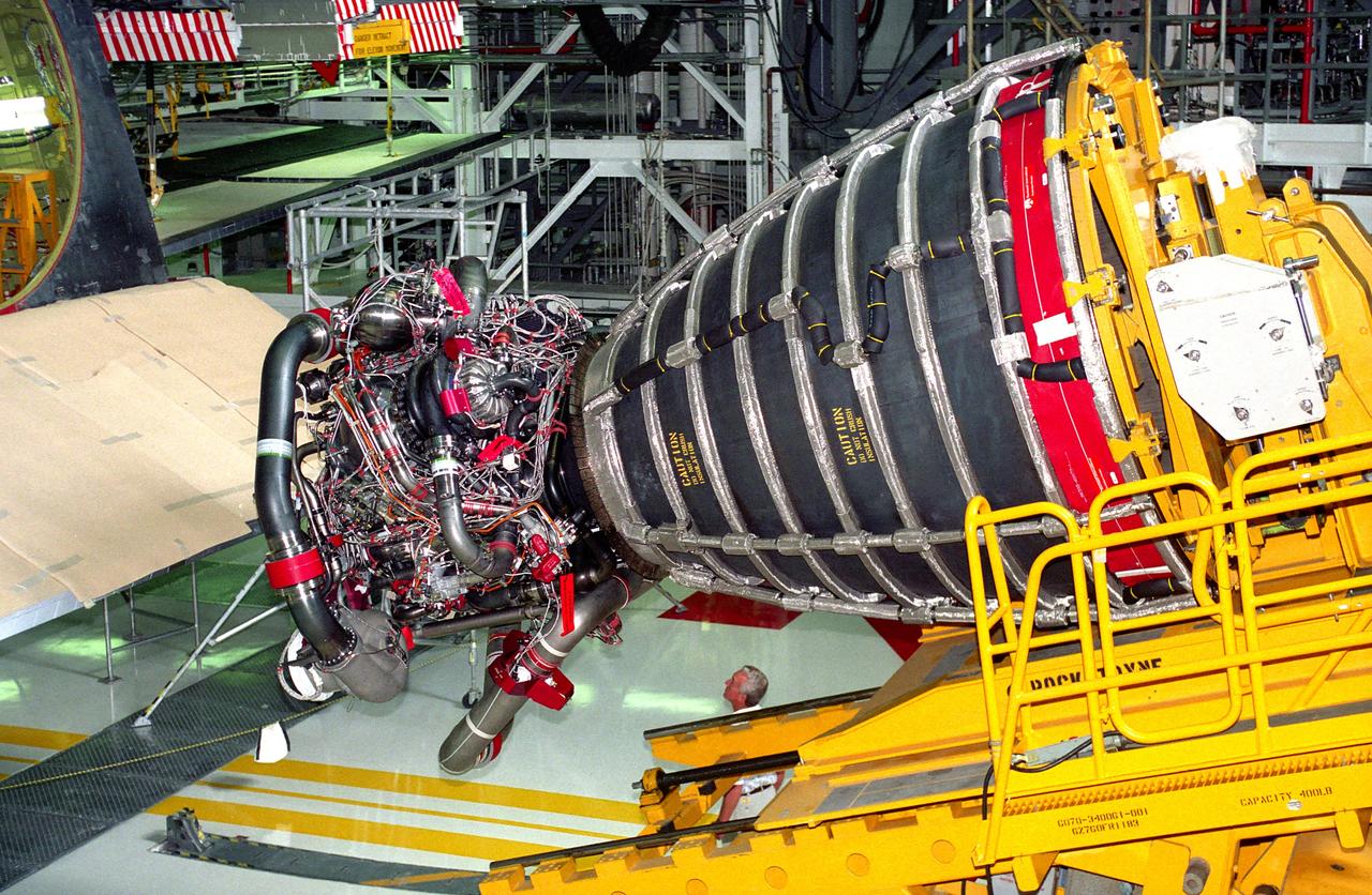
KENNEDY SPACE CENTER, FLA. - Space Shuttle Main Engine (SSME) No. 2036, the first of the new Block 1 engines to fly, awaits installation into position one of the orbiter Discovery in Orbiter Processing Facility 2 during preparation of the spaceplane for the STS-70 mission. The advanced powerplant features a new high-pressure liquid oxygen turbopump, a two-duct powerhead, a baffleless main injector, a single-coil heat exchanger and start sequence modifications. These modifications are designed to improve both engine performance and safety.
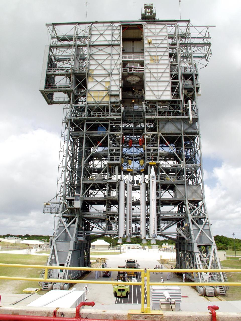
KENNEDY SPACE CENTER, FLA. -- On Launch Pad 17-A, Cape Canaveral Air Force Station, four solid rocket boosters are lifted for mating to a Boeing Delta II rocket. The rocket will be the launch vehicle for the CONTOUR spacecraft, scheduled to launch July 1. CONTOUR will provide the first detailed look into the heart of a comet -- the nucleus. The spacecraft will fly close to at least two comets, Encke and Schwassmann-Wachmann 3, taking pictures of the nucleus while analyzing the gas and dust that surround these rocky, icy building blocks of the solar system.
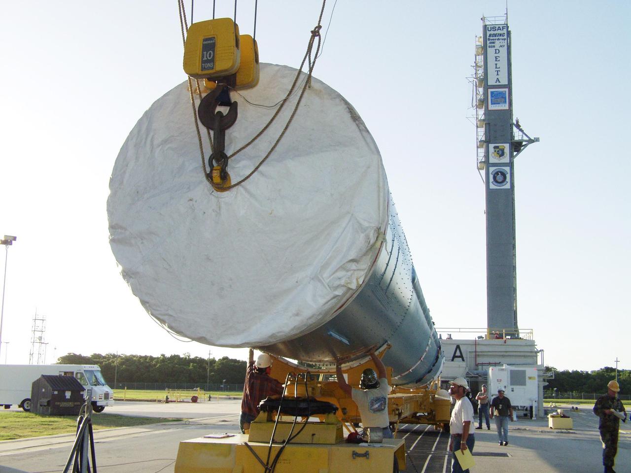
KENNEDY SPACE CENTER, FLA. - On Cape Canaveral Air Force Station Pad 17-A, the first stage of a Delta II rocket is lifted to vertical. The rocket is the launch vehicle for the CONTOUR spacecraft, scheduled to launch July 1. CONTOUR will provide the first detailed look into the heart of a comet -- the nucleus. The spacecraft will fly close to at least two comets, Encke and Schwassmann-Wachmann 3, taking pictures of the nucleus while analyzing the gas and dust that surround these rocky, icy building blocks of the solar system.
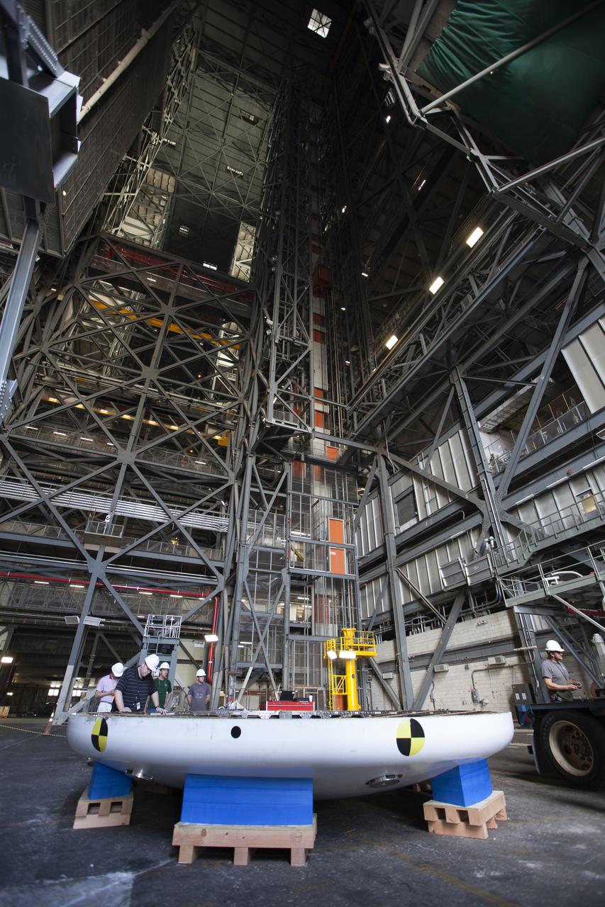
Inside High Bay 2 in the Vehicle Assembly Building (VAB) at NASA's Kennedy Space Center in Florida, the Orion heat shield from Exploration Flight Test-1 is secured on foam blocks. The heat shield is being transferred from the Orion Program to the Ground Systems Development and Operations Program, Landing and Recovery Operations. In the VAB, the heat shield will be integrated with the Orion ground test article and used for future underway recovery testing.
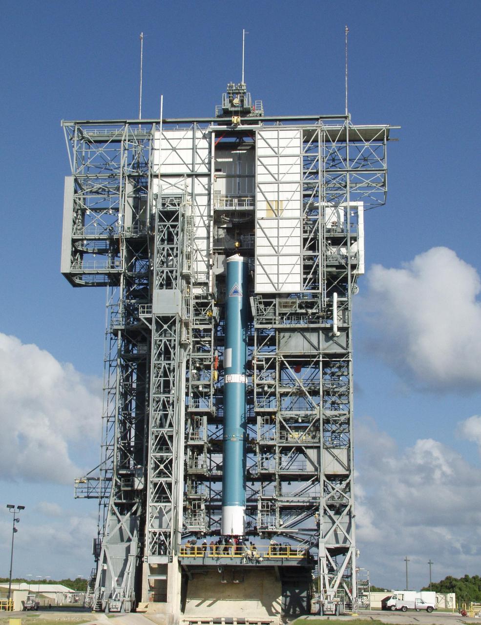
KENNEDY SPACE CENTER, FLA. -- On Launch Pad 17-A, Cape Canaveral Air Force Station, the Boeing Delta II rocket is lifted up the gantry. The rocket is the launch vehicle for the CONTOUR spacecraft, scheduled to launch July 1. CONTOUR will provide the first detailed look into the heart of a comet -- the nucleus. The spacecraft will fly close to at least two comets, Encke and Schwassmann-Wachmann 3, taking pictures of the nucleus while analyzing the gas and dust that surround these rocky, icy building blocks of the solar system.

By August, 2024, the four dams blocking the flow of the Klamath River in California and Oregon were removed. After more than 100 years, nearly 640 km of salmon habitat were restored. Two of the dams and their reservoirs, Copco 1 and Copco 2 in northern California, are shown before and after removal. The images were acquired July 18, 2024 and August 15, 2020, cover an area of 16.5 by 22.5 km, and are located at 42.1 degrees north, 122.2 degrees west. https://photojournal.jpl.nasa.gov/catalog/PIA26448
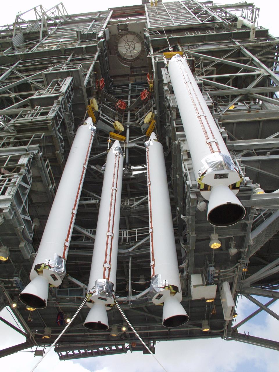
KENNEDY SPACE CENTER, FLA. -- On Launch Pad 17-A, Cape Canaveral Air Force Station, four solid rocket boosters are lifted for mating to a Boeing Delta II rocket. The rocket will be the launch vehicle for the CONTOUR spacecraft, scheduled to launch July 1. CONTOUR will provide the first detailed look into the heart of a comet -- the nucleus. The spacecraft will fly close to at least two comets, Encke and Schwassmann-Wachmann 3, taking pictures of the nucleus while analyzing the gas and dust that surround these rocky, icy building blocks of the solar system.
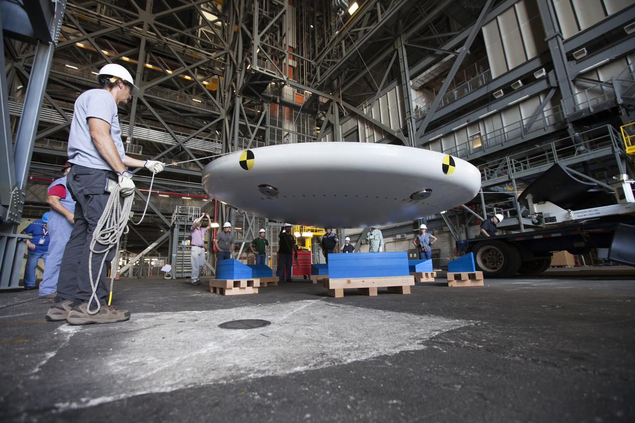
Inside High Bay 2 in the Vehicle Assembly Building (VAB) at NASA's Kennedy Space Center in Florida, workers monitor the progress as a crane lowers the Orion heat shield from Exploration Flight Test-1 onto foam blocks. The heat shield is being transferred from the Orion Program to the Ground Systems Development and Operations Program, Landing and Recovery Operations. In the VAB, the heat shield will be integrated with the Orion ground test article and used for future underway recovery testing.
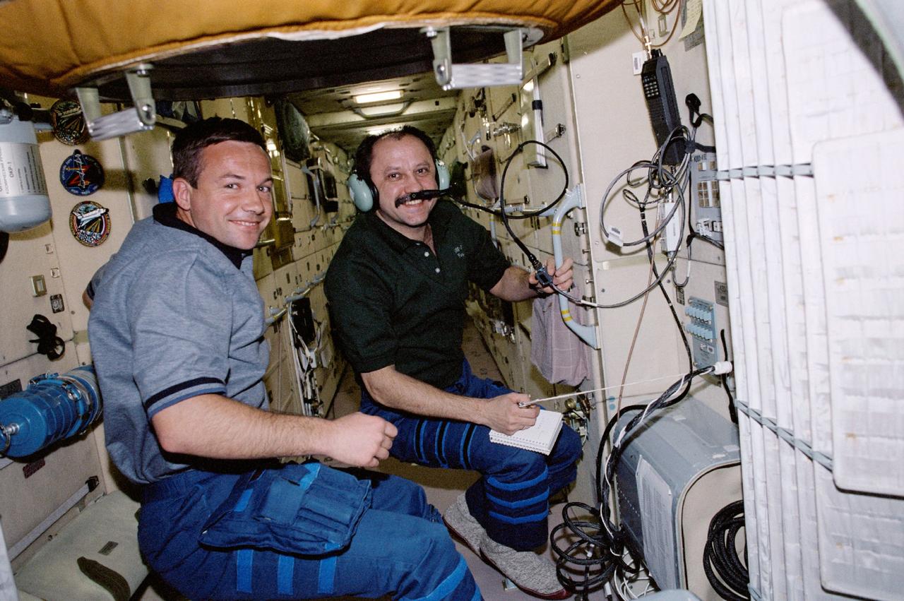
STS100-343-020 (19 April-1 May 2001) --- Cosmonaut Yuri V. Lonchakov (left), STS-100 mission specialist, observes as Yury V. Usachev, Expedition Two commander, talks to amateur radio operators on the ground from a special work station on the functional cargo block (FGB) or Zarya module of the International Space Station (ISS). The two represent Rosaviakosmos.
KENNEDY SPACE CENTER, FLA. -- The Pressurized Mating Adapter-2 (PMA-2) is processed in KSC's Space Station Processing Facility. This PMA is a cone-shaped connector to Node 1, the space station's structural building block. The node and two PMAs will together make up the first U.S. element of the ISS and are scheduled to be launched aboard the Space Shuttle Endeavour on STS-88.

KENNEDY SPACE CENTER, FLA. -- On Launch Pad 17-A, Cape Canaveral Air Force Station, a technician works beneath the Boeing Delta II rocket that will be the launch vehicle for the CONTOUR spacecraft, scheduled to launch July 1. CONTOUR will provide the first detailed look into the heart of a comet -- the nucleus. The spacecraft will fly close to at least two comets, Encke and Schwassmann-Wachmann 3, taking pictures of the nucleus while analyzing the gas and dust that surround these rocky, icy building blocks of the solar system.

Workmen at the Kennedy Space Center position the nose cone for the 204LM-1, an unmanned Apollo mission that tested the Apollo Lunar Module (LM) in Earth orbit. Also known as Apollo 5, the spacecraft was launched on the fourth Saturn IBC launch vehicle. Developed by the Marshall Space Flight Center (MSFC) as an interim vehicle in MSFC's "building block" approach to the Saturn rocket development, the Saturn IBC utilized Saturn I technology to further develop and refine a larger booster and the Apollo spacecraft capabilities required for the manned lunar missions.
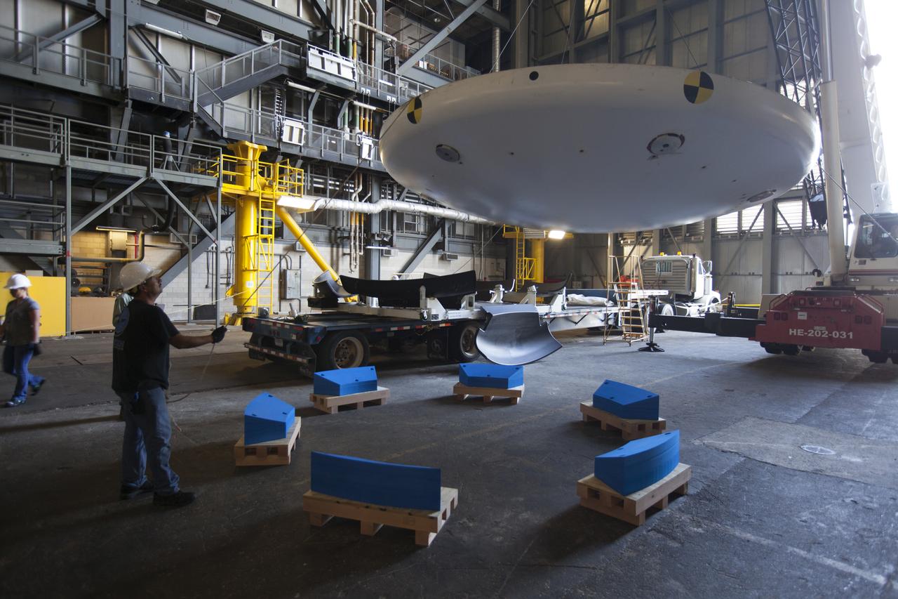
Inside High Bay 2 in the Vehicle Assembly Building (VAB) at NASA's Kennedy Space Center in Florida, a worker monitors the progress as a crane lowers the Orion heat shield from Exploration Flight Test-1 onto foam blocks. The heat shield is being transferred from the Orion Program to the Ground Systems Development and Operations Program, Landing and Recovery Operations. In the VAB, the heat shield will be integrated with the Orion ground test article and used for future underway recovery testing.

KENNEDY SPACE CENTER, FLA. -- On Cape Canaveral Air Force Station Pad 17-A, the Boeing Delta II rocket is lifted up the gantry. The rocket is the launch vehicle for the CONTOUR spacecraft, scheduled to launch July 1. CONTOUR will provide the first detailed look into the heart of a comet -- the nucleus. The spacecraft will fly close to at least two comets, Encke and Schwassmann-Wachmann 3, taking pictures of the nucleus while analyzing the gas and dust that surround these rocky, icy building blocks of the solar system.
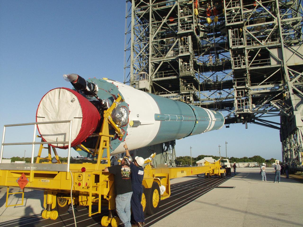
KENNEDY SPACE CENTER, FLA. - On Cape Canaveral Air Force Station Pad 17-A, workers check the lower portion of the Boeing Delta II rocket as it is lifted off the transporter. The rocket is the launch vehicle for the CONTOUR spacecraft, scheduled to launch July 1. CONTOUR will provide the first detailed look into the heart of a comet -- the nucleus. The spacecraft will fly close to at least two comets, Encke and Schwassmann-Wachmann 3, taking pictures of the nucleus while analyzing the gas and dust that surround these rocky, icy building blocks of the solar system.

Workmen at the Kennedy Space Center position the nose cone for the 204LM-1, an unmanned Apollo mission that tested the Apollo Lunar Module (LM) in Earth orbit. Also known as Apollo 5, the spacecraft was launched on the fourth Saturn IBC launch vehicle. Developed by the Marshall Space Flight Center (MSFC) as an interim vehicle in MSFC's "building block" approach to the Saturn rocket development, the Saturn IBC utilized Saturn I technology to further develop and refine a larger booster and the Apollo spacecraft capabilities required for the manned lunar missions.
KENNEDY SPACE CENTER, FLA. -- With the container removed, the Comet Nucleus Tour (CONTOUR) spacecraft is ready for fairing encapsulation. CONTOUR will provide the first detailed look into the heart of a comet -- the nucleus. Flying as close as 60 miles (100 kilometers) to at least two comets, the spacecraft will take the sharpest pictures yet of a nucleus while analyzing the gas and dust that surround these rocky, icy building blocks of the solar system. Launch of CONTOUR aboard a Boeing Delta II rocket is scheduled for July 1, 2002
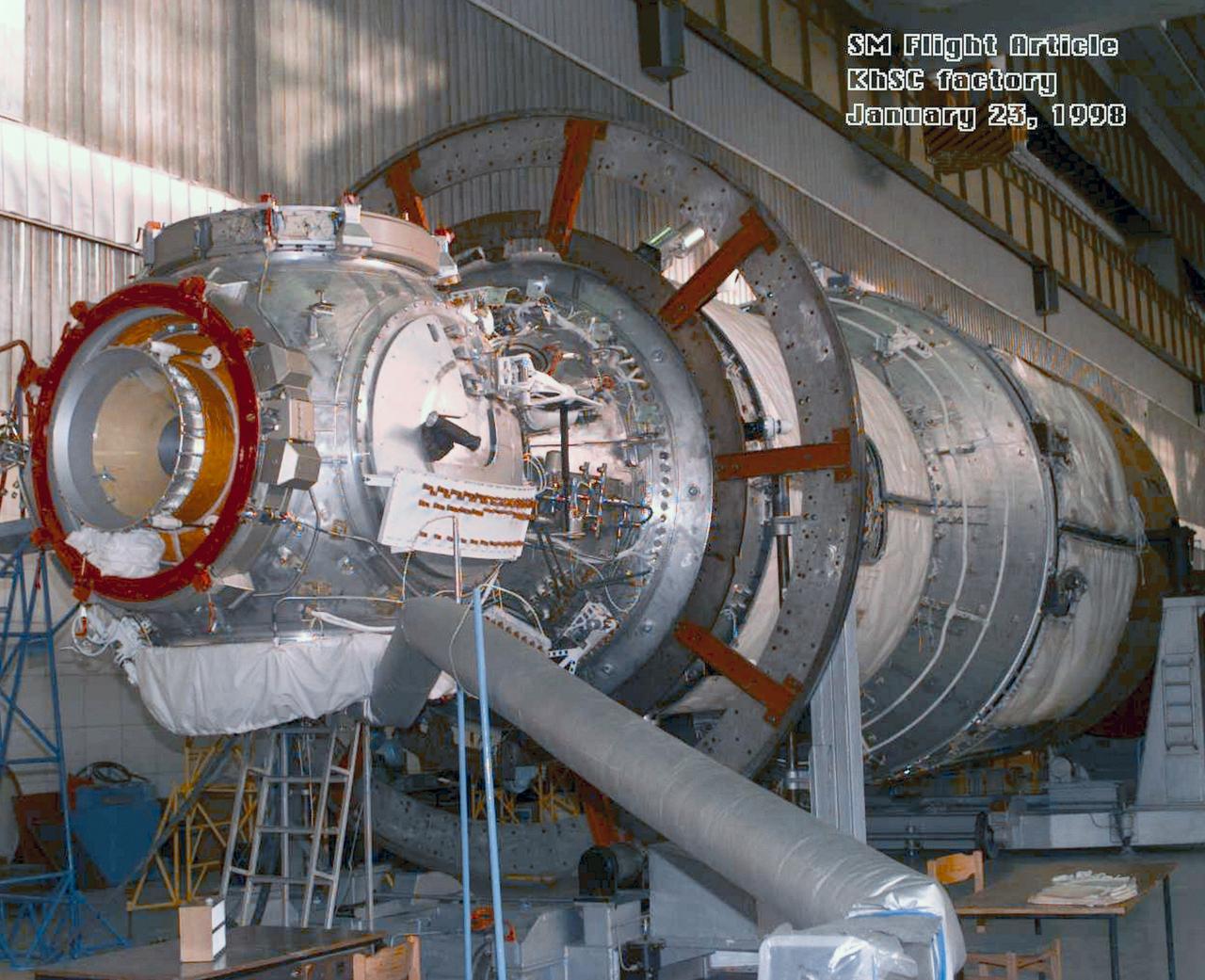
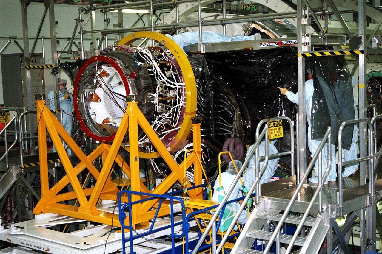
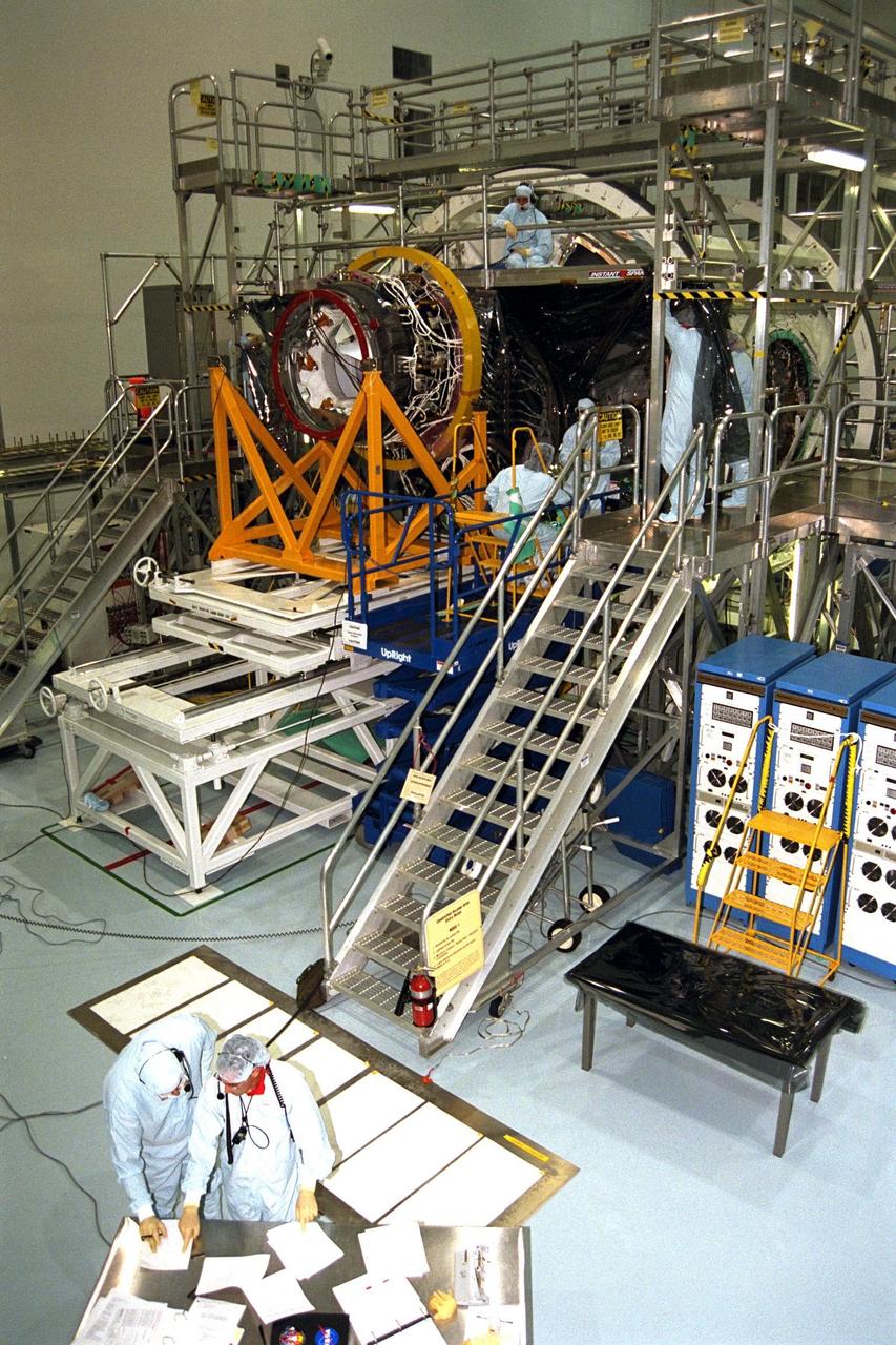
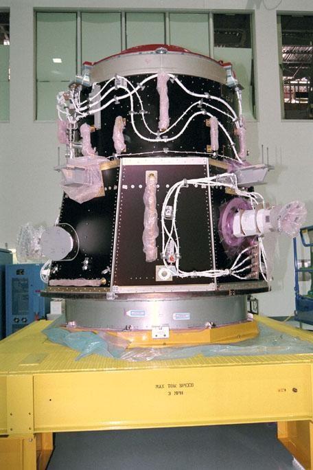
S98-04906 (23 Jan. 1998) --- A three-quarter frontal view of the flight article of the Service Module (SM) for the International Space Station (ISS). The first fully Russian contribution to ISS, the SM will provide early power, propulsion, life support, communications and living quarters for the station. It will be the third station element to be launched and join the United States-funded, Russian-built Functional Cargo Block (FGB) and the United States connecting module Node 1 in orbit.
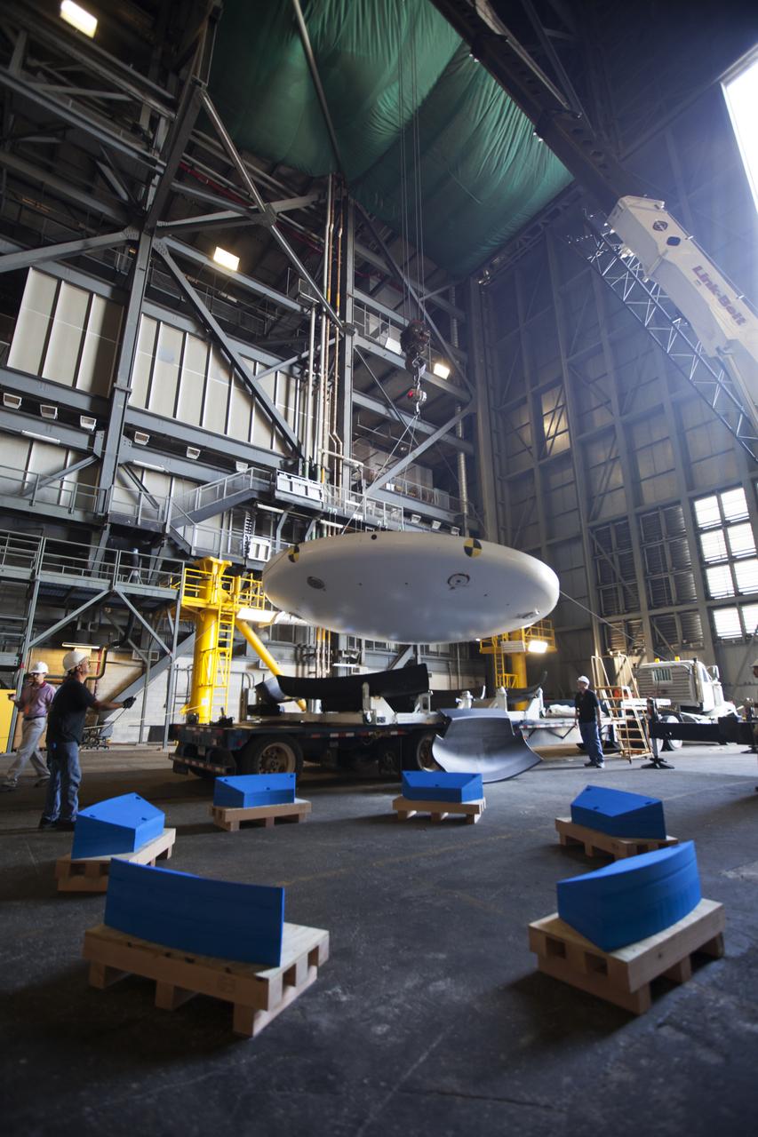
Inside High Bay 2 in the Vehicle Assembly Building (VAB) at NASA's Kennedy Space Center in Florida, a crane lifts the Orion heat shield from Exploration Flight Test-1 up off its transporter. It will be lowered onto foam blocks. The heat shield is being transferred from the Orion Program to the Ground Systems Development and Operations Program, Landing and Recovery Operations. In the VAB, the heat shield will be integrated with the Orion ground test article and used for future underway recovery testing.
KENNEDY SPACE CENTER, FLA. -- On Launch Pad 17-A, Cape Canaveral Air Force Station, workers oversee the lifting of the Boeing Delta II rocket into the gantry above. The rocket is the launch vehicle for the CONTOUR spacecraft, scheduled to launch July 1. CONTOUR will provide the first detailed look into the heart of a comet -- the nucleus. The spacecraft will fly close to at least two comets, Encke and Schwassmann-Wachmann 3, taking pictures of the nucleus while analyzing the gas and dust that surround these rocky, icy building blocks of the solar system.
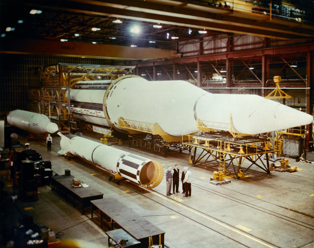
Progress in the Saturn program, depicted below, was described by Dr. Wernher von Braun, Marshall Space Flight Center (MSFC) Director, in an appearance before the Senate Committee of Aeronautical and Space Sciences. "The flight configuration of the giant three-stage Saturn C-1 rocket (later called Saturn I Block I) is seen in the Fabrication and Assembly Engineering Division at MSFC. Dwarfed by the 180-foot C-1 are a Juno II rocket (left rear) and a Mercury-Redstone rocket (front foreground). The C-1 (first version of the Saturn rocket) is composed of an S-1 first stage or booster (rear), powered by eight H-1 engines having a thrust of 1,500,000 pounds, followed by a dummy S-IV second stage and a dummy S-V third stage. The "live" S-IV for later flights, under development by Douglas Aircraft Co., will be powered by four Pratt Whitney LR-119 engines having 17,500,000 pounds thrust each. The live S-V, under development by Convair Division of General Dynamics Corp., will use two LR-119 engines. With all three stages live, the C-1 will be capable of placing 19,000 pounds into a 300-mile Earth orbit, sending 5,000 pounds to escape velocity, or lofting 2,500 pounds to Mars or Venus. The second version Saturn C-2 (later called Saturn 1 Block II) would double these capabilities. Early C-1 flights will employ a live S-1 with dummy upper stages. The first such flight is scheduled late this year."
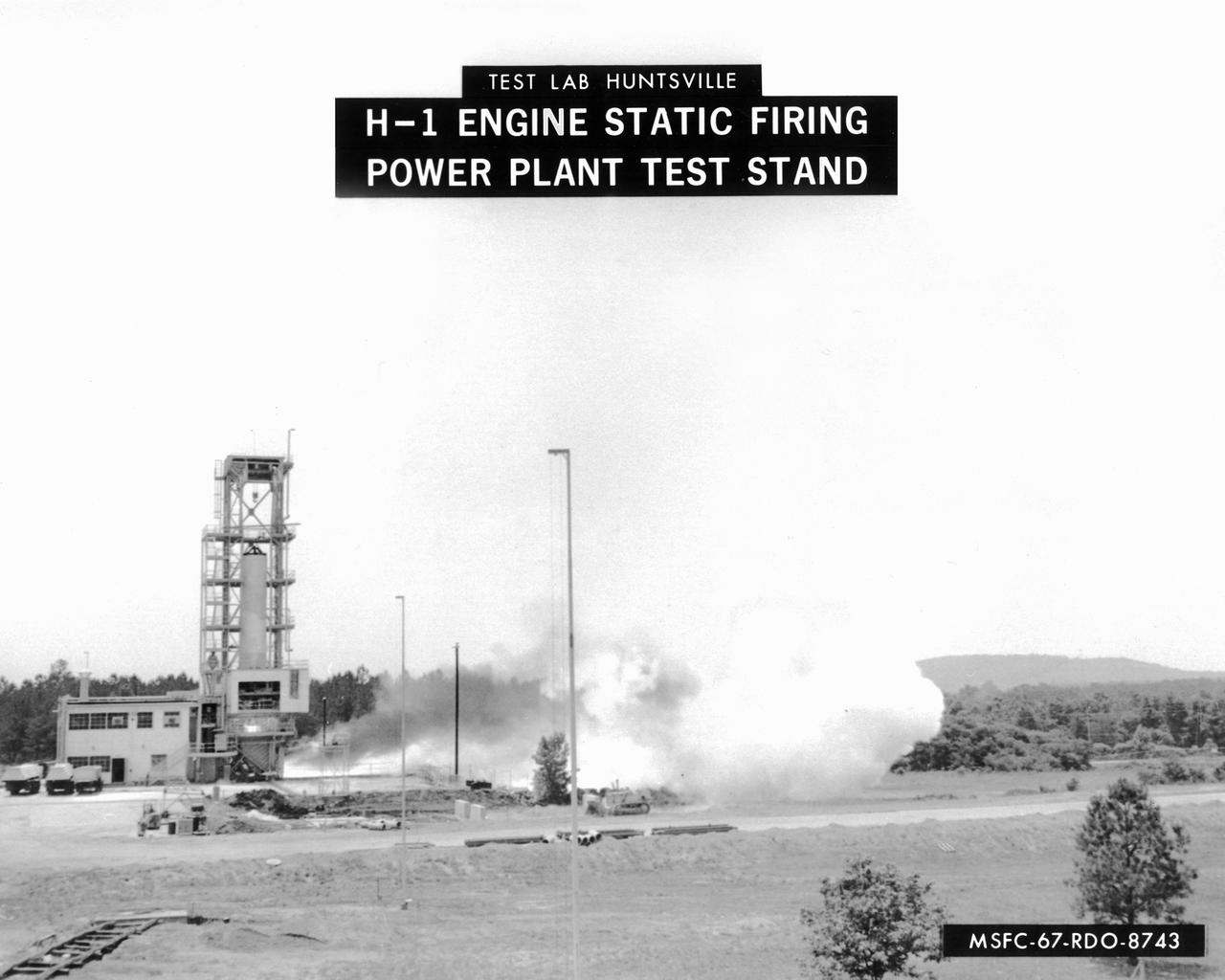
This image depicts a firing of a single H-1 engine at the Marshall Space Flight Center’s (MSFC’s) Power Plant test stand. This 1950s test stand, inherited from the Army, was used to test fire engines until the Test Area was completed in the latter 1960s. The H-1 engine was the workhorse of the first Saturn launch vehicles and used in the Saturn I, Block 1 and II, and in the Saturn IB. The eight H-1 engines were attached to a thrust frame on the vehicle’s aft end in two different ways. Four engines are rigidly attached to the inboard position and canted at a three degree angle to the long axis of the booster. The other four engines, mounted in the outboard position, are canted at six degrees.
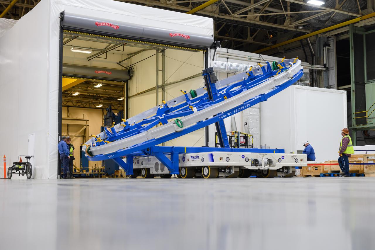
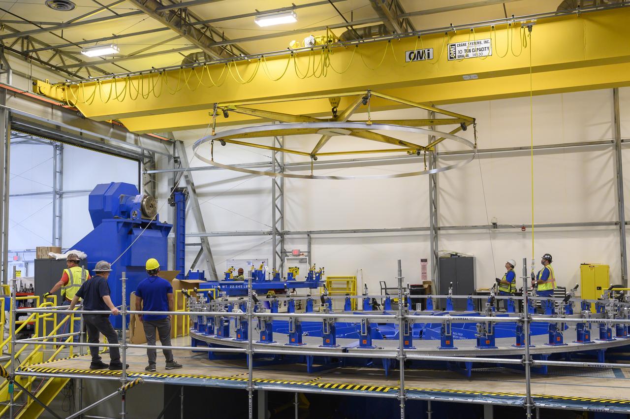
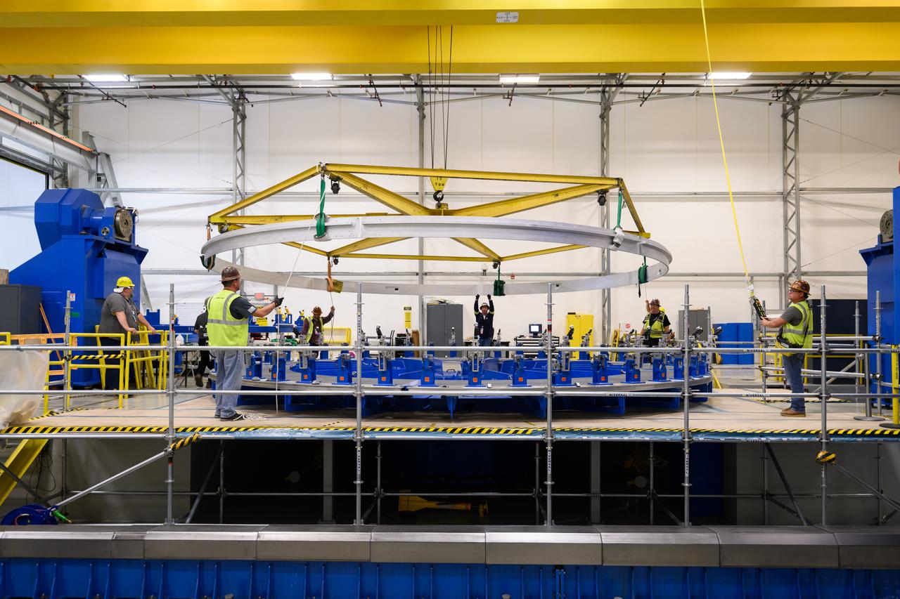
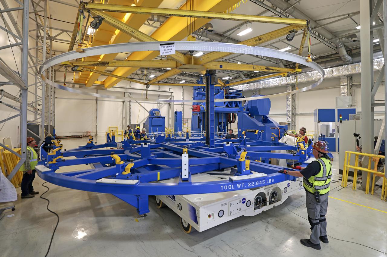
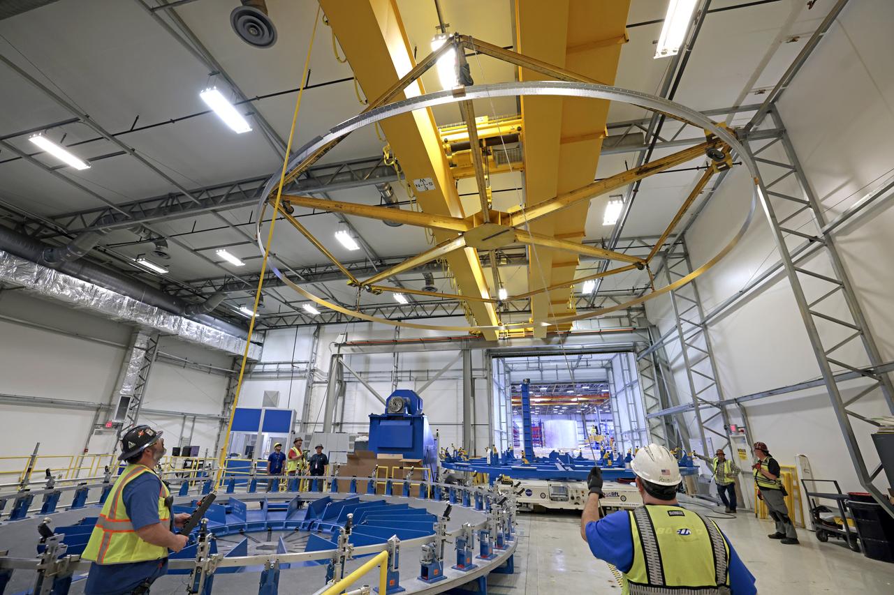
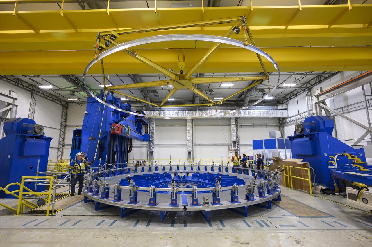
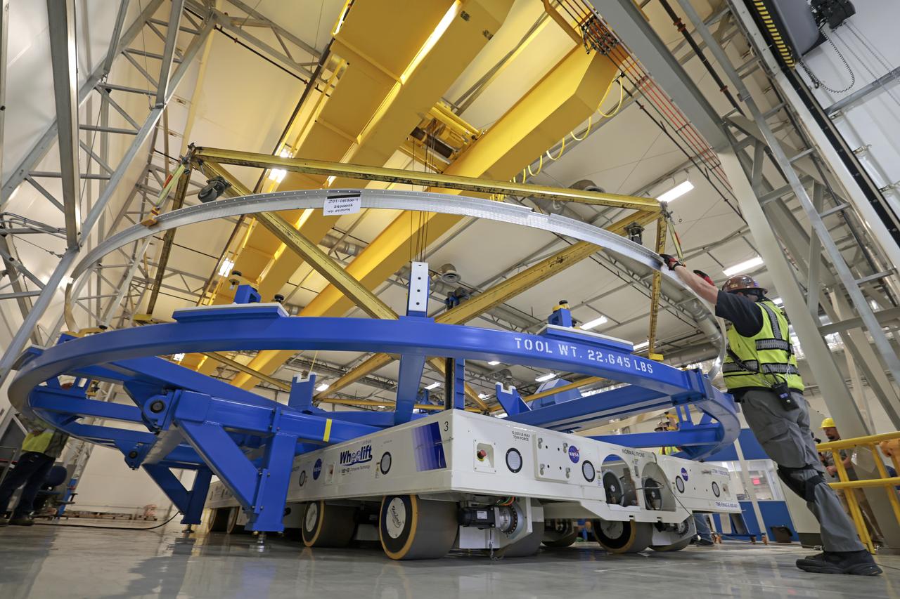
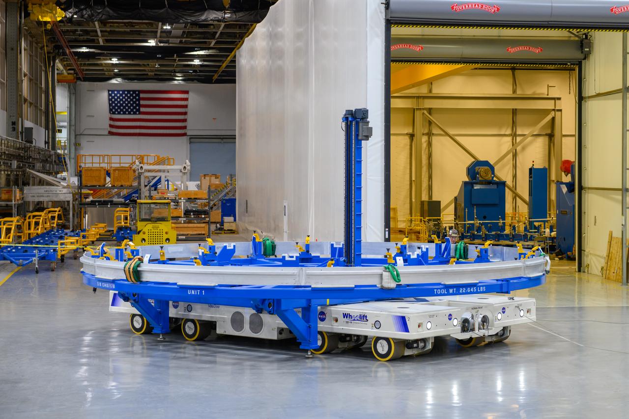
Technicians at NASA’s Michoud Assembly Facility in New Orleans lift a ring for the Exploration Upper Stage (EUS) of the SLS (Space Launch System) rocket to move it to another location in the 43-acre factory for further inspection and production. Flight hardware of the SLS EUS, a more powerful in-space propulsion stage beginning with Artemis IV, is in early production at Michoud. The rings make up the barrel sections for the flight hardware. The Exploration Upper Stage will be used on the second configuration of the SLS rocket, known as Block 1B, and will provide in-space propulsion to send astronauts in NASA’s Orion spacecraft and heavy cargo on a precise trajectory to the Moon. EUS will replace the interim cryogenic propulsion stage for the Block 1 configuration of SLS. It has larger propellant tanks and four RL10 engines, enabling SLS to launch 40% more cargo to the Moon along with crew. NASA and Boeing, the SLS lead contractor for the core stage and EUS, are currently manufacturing stages for Artemis II, III, IV, and V at the factory. NASA is working to land the first woman and first person of color on the Moon under Artemis. SLS is part of NASA’s backbone for deep space exploration, along with Orion and the Gateway in orbit around the Moon. SLS is the only rocket that can send Orion, astronauts, and supplies to the Moon in a single mission.
Technicians at NASA’s Michoud Assembly Facility in New Orleans lift a ring for the Exploration Upper Stage (EUS) of the SLS (Space Launch System) rocket to move it to another location in the 43-acre factory for further inspection and production. Flight hardware of the SLS EUS, a more powerful in-space propulsion stage beginning with Artemis IV, is in early production at Michoud. The rings make up the barrel sections for the flight hardware. The Exploration Upper Stage will be used on the second configuration of the SLS rocket, known as Block 1B, and will provide in-space propulsion to send astronauts in NASA’s Orion spacecraft and heavy cargo on a precise trajectory to the Moon. EUS will replace the interim cryogenic propulsion stage for the Block 1 configuration of SLS. It has larger propellant tanks and four RL10 engines, enabling SLS to launch 40% more cargo to the Moon along with crew. NASA and Boeing, the SLS lead contractor for the core stage and EUS, are currently manufacturing stages for Artemis II, III, IV, and V at the factory. NASA is working to land the first woman and first person of color on the Moon under Artemis. SLS is part of NASA’s backbone for deep space exploration, along with Orion and the Gateway in orbit around the Moon. SLS is the only rocket that can send Orion, astronauts, and supplies to the Moon in a single mission.
Technicians at NASA’s Michoud Assembly Facility in New Orleans lift a ring for the Exploration Upper Stage (EUS) of the SLS (Space Launch System) rocket to move it to another location in the 43-acre factory for further inspection and production. Flight hardware of the SLS EUS, a more powerful in-space propulsion stage beginning with Artemis IV, is in early production at Michoud. The rings make up the barrel sections for the flight hardware. The Exploration Upper Stage will be used on the second configuration of the SLS rocket, known as Block 1B, and will provide in-space propulsion to send astronauts in NASA’s Orion spacecraft and heavy cargo on a precise trajectory to the Moon. EUS will replace the interim cryogenic propulsion stage for the Block 1 configuration of SLS. It has larger propellant tanks and four RL10 engines, enabling SLS to launch 40% more cargo to the Moon along with crew. NASA and Boeing, the SLS lead contractor for the core stage and EUS, are currently manufacturing stages for Artemis II, III, IV, and V at the factory. NASA is working to land the first woman and first person of color on the Moon under Artemis. SLS is part of NASA’s backbone for deep space exploration, along with Orion and the Gateway in orbit around the Moon. SLS is the only rocket that can send Orion, astronauts, and supplies to the Moon in a single mission.
Technicians at NASA’s Michoud Assembly Facility in New Orleans lift a ring for the Exploration Upper Stage (EUS) of the SLS (Space Launch System) rocket to move it to another location in the 43-acre factory for further inspection and production. Flight hardware of the SLS EUS, a more powerful in-space propulsion stage beginning with Artemis IV, is in early production at Michoud. The rings make up the barrel sections for the flight hardware. The Exploration Upper Stage will be used on the second configuration of the SLS rocket, known as Block 1B, and will provide in-space propulsion to send astronauts in NASA’s Orion spacecraft and heavy cargo on a precise trajectory to the Moon. EUS will replace the interim cryogenic propulsion stage for the Block 1 configuration of SLS. It has larger propellant tanks and four RL10 engines, enabling SLS to launch 40% more cargo to the Moon along with crew. NASA and Boeing, the SLS lead contractor for the core stage and EUS, are currently manufacturing stages for Artemis II, III, IV, and V at the factory. NASA is working to land the first woman and first person of color on the Moon under Artemis. SLS is part of NASA’s backbone for deep space exploration, along with Orion and the Gateway in orbit around the Moon. SLS is the only rocket that can send Orion, astronauts, and supplies to the Moon in a single mission.
Technicians at NASA’s Michoud Assembly Facility in New Orleans lift a ring for the Exploration Upper Stage (EUS) of the SLS (Space Launch System) rocket to move it to another location in the 43-acre factory for further inspection and production. Flight hardware of the SLS EUS, a more powerful in-space propulsion stage beginning with Artemis IV, is in early production at Michoud. The rings make up the barrel sections for the flight hardware. The Exploration Upper Stage will be used on the second configuration of the SLS rocket, known as Block 1B, and will provide in-space propulsion to send astronauts in NASA’s Orion spacecraft and heavy cargo on a precise trajectory to the Moon. EUS will replace the interim cryogenic propulsion stage for the Block 1 configuration of SLS. It has larger propellant tanks and four RL10 engines, enabling SLS to launch 40% more cargo to the Moon along with crew. NASA and Boeing, the SLS lead contractor for the core stage and EUS, are currently manufacturing stages for Artemis II, III, IV, and V at the factory. NASA is working to land the first woman and first person of color on the Moon under Artemis. SLS is part of NASA’s backbone for deep space exploration, along with Orion and the Gateway in orbit around the Moon. SLS is the only rocket that can send Orion, astronauts, and supplies to the Moon in a single mission.
Technicians at NASA’s Michoud Assembly Facility in New Orleans lift a ring for the Exploration Upper Stage (EUS) of the SLS (Space Launch System) rocket to move it to another location in the 43-acre factory for further inspection and production. Flight hardware of the SLS EUS, a more powerful in-space propulsion stage beginning with Artemis IV, is in early production at Michoud. The rings make up the barrel sections for the flight hardware. The Exploration Upper Stage will be used on the second configuration of the SLS rocket, known as Block 1B, and will provide in-space propulsion to send astronauts in NASA’s Orion spacecraft and heavy cargo on a precise trajectory to the Moon. EUS will replace the interim cryogenic propulsion stage for the Block 1 configuration of SLS. It has larger propellant tanks and four RL10 engines, enabling SLS to launch 40% more cargo to the Moon along with crew. NASA and Boeing, the SLS lead contractor for the core stage and EUS, are currently manufacturing stages for Artemis II, III, IV, and V at the factory. NASA is working to land the first woman and first person of color on the Moon under Artemis. SLS is part of NASA’s backbone for deep space exploration, along with Orion and the Gateway in orbit around the Moon. SLS is the only rocket that can send Orion, astronauts, and supplies to the Moon in a single mission.
Technicians at NASA’s Michoud Assembly Facility in New Orleans lift a ring for the Exploration Upper Stage (EUS) of the SLS (Space Launch System) rocket to move it to another location in the 43-acre factory for further inspection and production. Flight hardware of the SLS EUS, a more powerful in-space propulsion stage beginning with Artemis IV, is in early production at Michoud. The rings make up the barrel sections for the flight hardware. The Exploration Upper Stage will be used on the second configuration of the SLS rocket, known as Block 1B, and will provide in-space propulsion to send astronauts in NASA’s Orion spacecraft and heavy cargo on a precise trajectory to the Moon. EUS will replace the interim cryogenic propulsion stage for the Block 1 configuration of SLS. It has larger propellant tanks and four RL10 engines, enabling SLS to launch 40% more cargo to the Moon along with crew. NASA and Boeing, the SLS lead contractor for the core stage and EUS, are currently manufacturing stages for Artemis II, III, IV, and V at the factory. NASA is working to land the first woman and first person of color on the Moon under Artemis. SLS is part of NASA’s backbone for deep space exploration, along with Orion and the Gateway in orbit around the Moon. SLS is the only rocket that can send Orion, astronauts, and supplies to the Moon in a single mission.
Technicians at NASA’s Michoud Assembly Facility in New Orleans lift a ring for the Exploration Upper Stage (EUS) of the SLS (Space Launch System) rocket to move it to another location in the 43-acre factory for further inspection and production. Flight hardware of the SLS EUS, a more powerful in-space propulsion stage beginning with Artemis IV, is in early production at Michoud. The rings make up the barrel sections for the flight hardware. The Exploration Upper Stage will be used on the second configuration of the SLS rocket, known as Block 1B, and will provide in-space propulsion to send astronauts in NASA’s Orion spacecraft and heavy cargo on a precise trajectory to the Moon. EUS will replace the interim cryogenic propulsion stage for the Block 1 configuration of SLS. It has larger propellant tanks and four RL10 engines, enabling SLS to launch 40% more cargo to the Moon along with crew. NASA and Boeing, the SLS lead contractor for the core stage and EUS, are currently manufacturing stages for Artemis II, III, IV, and V at the factory. NASA is working to land the first woman and first person of color on the Moon under Artemis. SLS is part of NASA’s backbone for deep space exploration, along with Orion and the Gateway in orbit around the Moon. SLS is the only rocket that can send Orion, astronauts, and supplies to the Moon in a single mission.