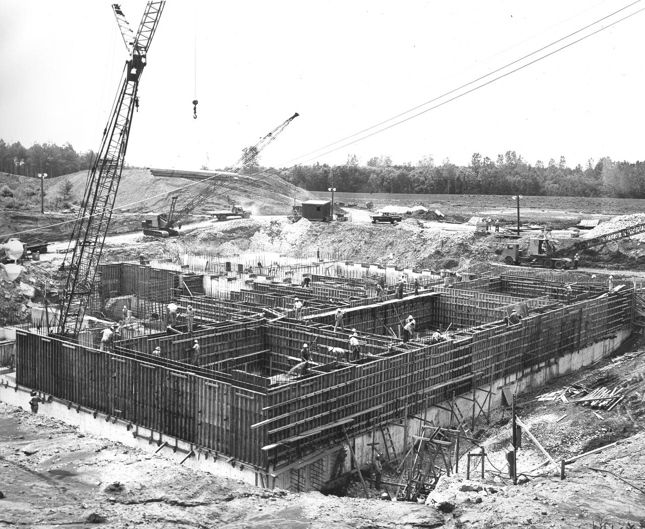
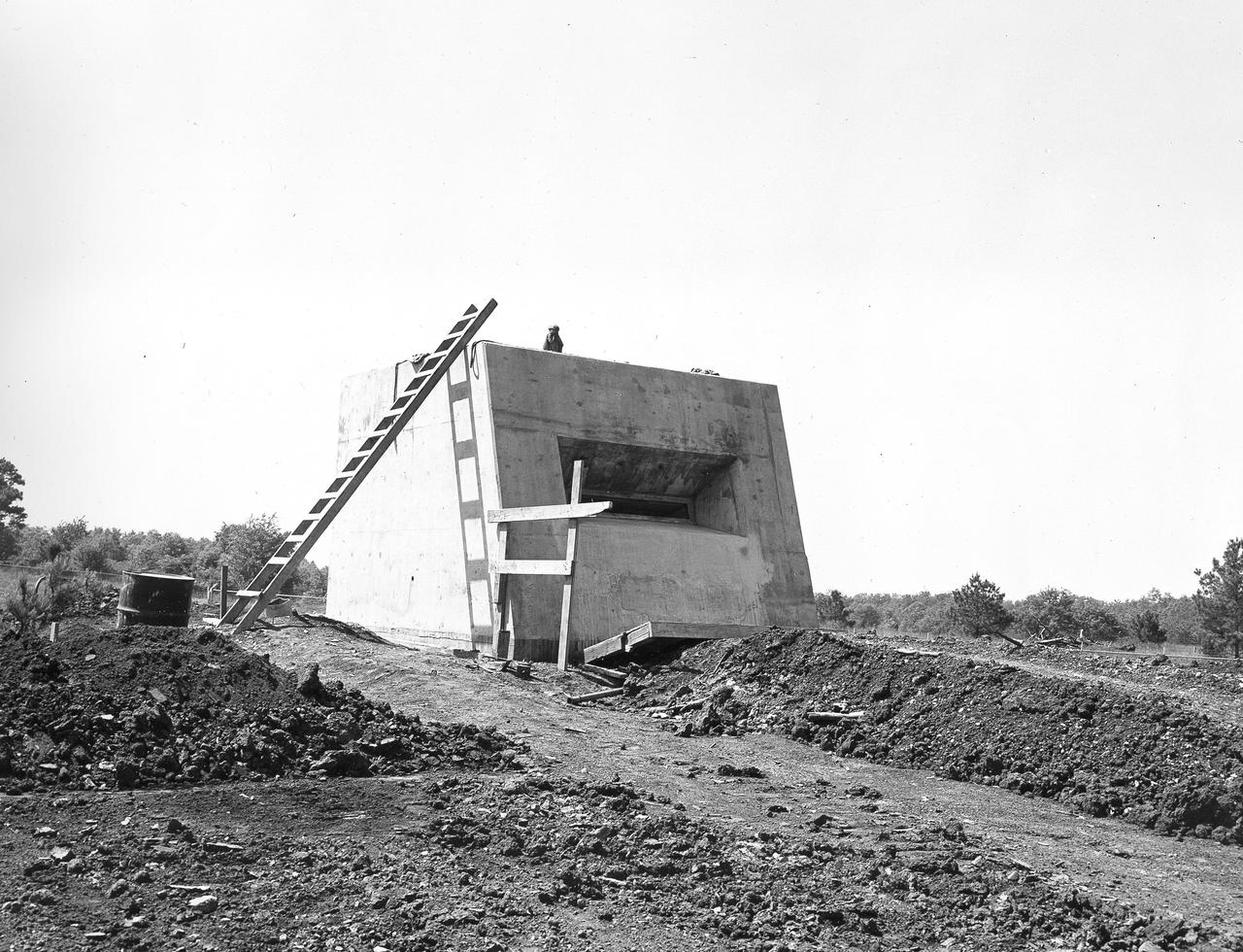
At its founding, the Marshall Space Flight Center (MSFC) inherited the Army’s Jupiter and Redstone test stands, but much larger facilities were needed for the giant stages of the Saturn V. From 1960 to 1964, the existing stands were remodeled and a sizable new test area was developed. The new comprehensive test complex for propulsion and structural dynamics was unique within the nation and the free world, and they remain so today because they were constructed with foresight to meet the future as well as on going needs. Construction of the S-IC Static test stand complex began in 1961 in the west test area of MSFC, and was completed in 1964. The S-IC static test stand was designed to develop and test the 138-ft long and 33-ft diameter Saturn V S-IC first stage, or booster stage, weighing in at 280,000 pounds. Required to hold down the brute force of a 7,500,000-pound thrust produced by 5 F-1 engines, the S-IC static test stand was designed and constructed with the strength of hundreds of tons of steel and 12,000,000 pounds of cement, planted down to bedrock 40 feet below ground level. The foundation walls, constructed with concrete and steel, are 4 feet thick. The base structure consists of four towers with 40-foot-thick walls extending upward 144 feet above ground level. The structure was topped by a crane with a 135-foot boom. With the boom in the upright position, the stand was given an overall height of 405 feet, placing it among the highest structures in Alabama at the time. In addition to the stand itself, related facilities were constructed during this time. Built directly east of the test stand was the Block House, which served as the control center for the test stand. The two were connected by a narrow access tunnel which housed the cables for the controls. This construction photo, taken November 15, 1962, depicts a view of the Block House.
At its founding, the Marshall Space Flight Center (MSFC) inherited the Army’s Jupiter and Redstone test stands, but much larger facilities were needed for the giant stages of the Saturn V. From 1960 to 1964, the existing stands were remodeled and a sizable new test area was developed. The new comprehensive test complex for propulsion and structural dynamics was unique within the nation and the free world, and they remain so today because they were constructed with foresight to meet the future as well as on going needs. Construction of the S-IC Static test stand complex began in 1961 in the west test area of MSFC, and was completed in 1964. The S-IC static test stand was designed to develop and test the 138-ft long and 33-ft diameter Saturn V S-IC first stage, or booster stage, weighing in at 280,000 pounds. Required to hold down the brute force of a 7,500,000-pound thrust produced by 5 F-1 engines, the S-IC static test stand was designed and constructed with the strength of hundreds of tons of steel and 12,000,000 pounds of cement, planted down to bedrock 40 feet below ground level. The foundation walls, constructed with concrete and steel, are 4 feet thick. The base structure consists of four towers with 40-foot-thick walls extending upward 144 feet above ground level. The structure was topped by a crane with a 135-foot boom. With the boom in the upright position, the stand was given an overall height of 405 feet, placing it among the highest structures in Alabama at the time. In addition to the stand itself, related facilities were constructed during this time. Built directly east of the test stand was the Block House, which served as the control center for the test stand. The two were connected by a narrow access tunnel which housed the cables for the controls. This construction photo, taken July 3, 1962, depicts the Block House with a portion of its concrete walls poured and exposed while many are still in the forms stage.
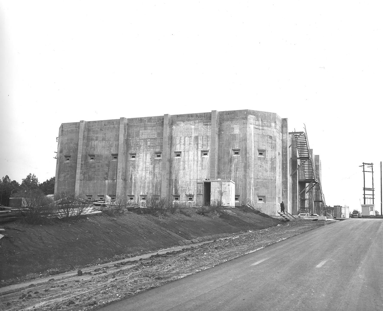
At its founding, the Marshall Space Flight Center (MSFC) inherited the Army’s Jupiter and Redstone test stands, but much larger facilities were needed for the giant stages of the Saturn V. From 1960 to 1964, the existing stands were remodeled and a sizable new test area was developed. The new comprehensive test complex for propulsion and structural dynamics was unique within the nation and the free world, and they remain so today because they were constructed with foresight to meet the future as well as on going needs. Construction of the S-IC Static test stand complex began in 1961 in the west test area of MSFC, and was completed in 1964. The S-IC static test stand was designed to develop and test the 138-ft long and 33-ft diameter Saturn V S-IC first stage, or booster stage, weighing in at 280,000 pounds. Required to hold down the brute force of a 7,500,000-pound thrust produced by 5 F-1 engines, the S-IC static test stand was designed and constructed with the strength of hundreds of tons of steel and 12,000,000 pounds of cement, planted down to bedrock 40 feet below ground level. The foundation walls, constructed with concrete and steel, are 4 feet thick. The base structure consists of four towers with 40-foot-thick walls extending upward 144 feet above ground level. The structure was topped by a crane with a 135-foot boom. With the boom in the upright position, the stand was given an overall height of 405 feet, placing it among the highest structures in Alabama at the time. In addition to the stand itself, related facilities were constructed during this time. Built directly east of the test stand was the Block House, which served as the control center for the test stand. The two were connected by a narrow access tunnel which housed the cables for the controls. In this photo taken February 4, 1963, the Block House exterior is complete.
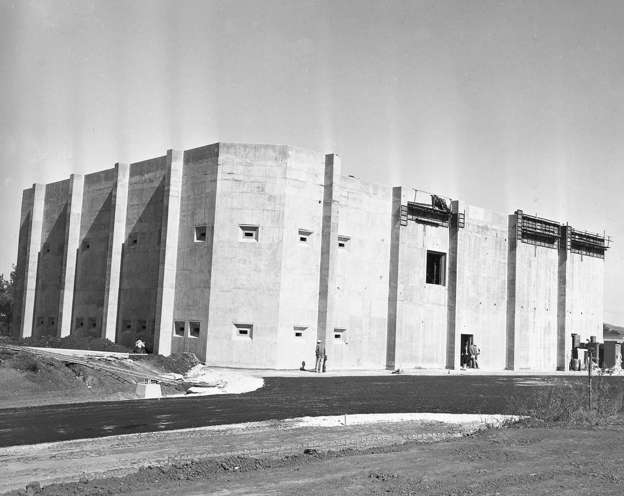
At its founding, the Marshall Space Flight Center (MSFC) inherited the Army’s Jupiter and Redstone test stands, but much larger facilities were needed for the giant stages of the Saturn V. From 1960 to 1964, the existing stands were remodeled and a sizable new test area was developed. The new comprehensive test complex for propulsion and structural dynamics was unique within the nation and the free world, and they remain so today because they were constructed with foresight to meet the future as well as on going needs. Construction of the S-IC Static test stand complex began in 1961 in the west test area of MSFC, and was completed in 1964. The S-IC static test stand was designed to develop and test the 138-ft long and 33-ft diameter Saturn V S-IC first stage, or booster stage, weighing in at 280,000 pounds. Required to hold down the brute force of a 7,500,000-pound thrust produced by 5 F-1 engines, the S-IC static test stand was designed and constructed with the strength of hundreds of tons of steel and 12,000,000 pounds of cement, planted down to bedrock 40 feet below ground level. The foundation walls, constructed with concrete and steel, are 4 feet thick. The base structure consists of four towers with 40-foot-thick walls extending upward 144 feet above ground level. The structure was topped by a crane with a 135-foot boom. With the boom in the upright position, the stand was given an overall height of 405 feet, placing it among the highest structures in Alabama at the time. In addition to the stand itself, related facilities were constructed during this time. Built directly east of the test stand was the Block House, which served as the control center for the test stand. The two were connected by a narrow access tunnel which housed the cables for the controls. This photograph, taken February 25, 1963, gives a close up look at the completed Block House. The side shown faces the S-IC Test Stand.
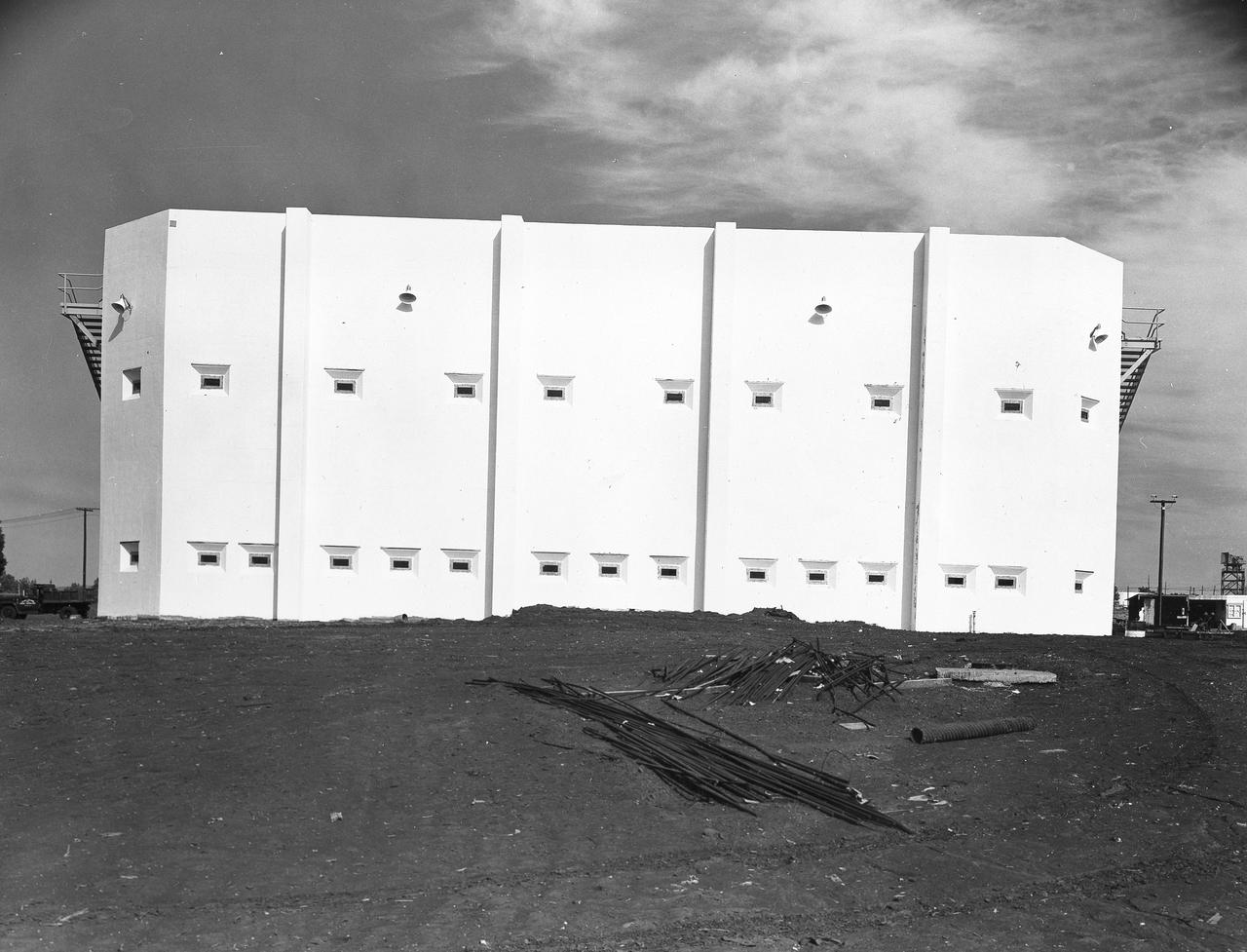
At its founding, the Marshall Space Flight Center (MSFC) inherited the Army’s Jupiter and Redstone test stands, but much larger facilities were needed for the giant stages of the Saturn V. From 1960 to 1964, the existing stands were remodeled and a sizable new test area was developed. The new comprehensive test complex for propulsion and structural dynamics was unique within the nation and the free world, and they remain so today because they were constructed with foresight to meet the future as well as on going needs. Construction of the S-IC Static test stand complex began in 1961 in the west test area of MSFC, and was completed in 1964. The S-IC static test stand was designed to develop and test the 138-ft long and 33-ft diameter Saturn V S-IC first stage, or booster stage, weighing in at 280,000 pounds. Required to hold down the brute force of a 7,500,000-pound thrust produced by 5 F-1 engines, the S-IC static test stand was designed and constructed with the strength of hundreds of tons of steel and 12,000,000 pounds of cement, planted down to bedrock 40 feet below ground level. The foundation walls, constructed with concrete and steel, are 4 feet thick. The base structure consists of four towers with 40-foot-thick walls extending upward 144 feet above ground level. The structure was topped by a crane with a 135-foot boom. With the boom in the upright position, the stand was given an overall height of 405 feet, placing it among the highest structures in Alabama at the time. In addition to the stand itself, related facilities were constructed during this time. Built directly east of the test stand was the Block House, which served as the control center for the test stand. The two were connected by a narrow access tunnel which housed the cables for the controls. This construction photo, taken October 26, 1962, depicts a nearly completed view of the Block House.
At its founding, the Marshall Space Flight Center (MSFC) inherited the Army’s Jupiter and Redstone test stands, but much larger facilities were needed for the giant stages of the Saturn V. From 1960 to 1964, the existing stands were remodeled and a sizable new test area was developed. The new comprehensive test complex for propulsion and structural dynamics was unique within the nation and the free world, and they remain so today because they were constructed with foresight to meet the future as well as on going needs. Construction of the S-IC Static test stand complex began in 1961 in the west test area of MSFC, and was completed in 1964. The S-IC static test stand was designed to develop and test the 138-ft long and 33-ft diameter Saturn V S-IC first stage, or booster stage, weighing in at 280,000 pounds. Required to hold down the brute force of a 7,500,000-pound thrust produced by 5 F-1 engines, the S-IC static test stand was designed and constructed with the strength of hundreds of tons of steel and 12,000,000 pounds of cement, planted down to bedrock 40 feet below ground level. The foundation walls, constructed with concrete and steel, are 4 feet thick. The base structure consists of four towers with 40-foot-thick walls extending upward 144 feet above ground level. The structure was topped by a crane with a 135-foot boom. With the boom in the upright position, the stand was given an overall height of 405 feet, placing it among the highest structures in Alabama at the time. In addition to the stand itself, related facilities were constructed during this time. Built directly east of the test stand was the Block House, which served as the control center for the test stand. The two were connected by a narrow access tunnel which housed the cables for the controls. This photo, taken February 2, 1962, shows the excavation of the Block House site.
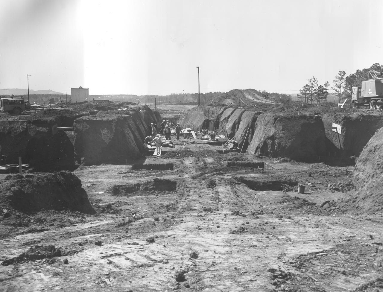
At its founding, the Marshall Space Flight Center (MSFC) inherited the Army’s Jupiter and Redstone test stands, but much larger facilities were needed for the giant stages of the Saturn V. From 1960 to 1964, the existing stands were remodeled and a sizable new test area was developed. The new comprehensive test complex for propulsion and structural dynamics was unique within the nation and the free world, and they remain so today because they were constructed with foresight to meet the future as well as on going needs. Construction of the S-IC Static test stand complex began in 1961 in the west test area of MSFC, and was completed in 1964. The S-IC static test stand was designed to develop and test the 138-ft long and 33-ft diameter Saturn V S-IC first stage, or booster stage, weighing in at 280,000 pounds. Required to hold down the brute force of a 7,500,000-pound thrust produced by 5 F-1 engines, the S-IC static test stand was designed and constructed with the strength of hundreds of tons of steel and 12,000,000 pounds of cement, planted down to bedrock 40 feet below ground level. The foundation walls, constructed with concrete and steel, are 4 feet thick. The base structure consists of four towers with 40-foot-thick walls extending upward 144 feet above ground level. The structure was topped by a crane with a 135-foot boom. With the boom in the upright position, the stand was given an overall height of 405 feet, placing it among the highest structures in Alabama at the time. In addition to the stand itself, related facilities were constructed during this time. Built directly east of the test stand was the Block House, which served as the control center for the test stand. The two were connected by a narrow access tunnel which housed the cables for the controls. This photo, taken January 23, 1962, shows the excavation of the Block House site.
At its founding, the Marshall Space Flight Center (MSFC) inherited the Army’s Jupiter and Redstone test stands, but much larger facilities were needed for the giant stages of the Saturn V. From 1960 to 1964, the existing stands were remodeled and a sizable new test area was developed. The new comprehensive test complex for propulsion and structural dynamics was unique within the nation and the free world, and they remain so today because they were constructed with foresight to meet the future as well as on going needs. Construction of the S-IC Static test stand complex began in 1961 in the west test area of MSFC, and was completed in 1964. The S-IC static test stand was designed to develop and test the 138-ft long and 33-ft diameter Saturn V S-IC first stage, or booster stage, weighing in at 280,000 pounds. Required to hold down the brute force of a 7,500,000-pound thrust produced by 5 F-1 engines, the S-IC static test stand was designed and constructed with the strength of hundreds of tons of steel and 12,000,000 pounds of cement, planted down to bedrock 40 feet below ground level. The foundation walls, constructed with concrete and steel, are 4 feet thick. The base structure consists of four towers with 40-foot-thick walls extending upward 144 feet above ground level. The structure was topped by a crane with a 135-foot boom. With the boom in the upright position, the stand was given an overall height of 405 feet, placing it among the highest structures in Alabama at the time. In addition to the stand itself, related facilities were constructed during this time. Built directly east of the test stand was the Block House, which served as the control center for the test stand. The two were connected by a narrow access tunnel which housed the cables for the controls. This photograph taken February 4, 1963, gives an impressive look at the Block House looking directly through the ever-growing four towers of the S-IC Test Stand.
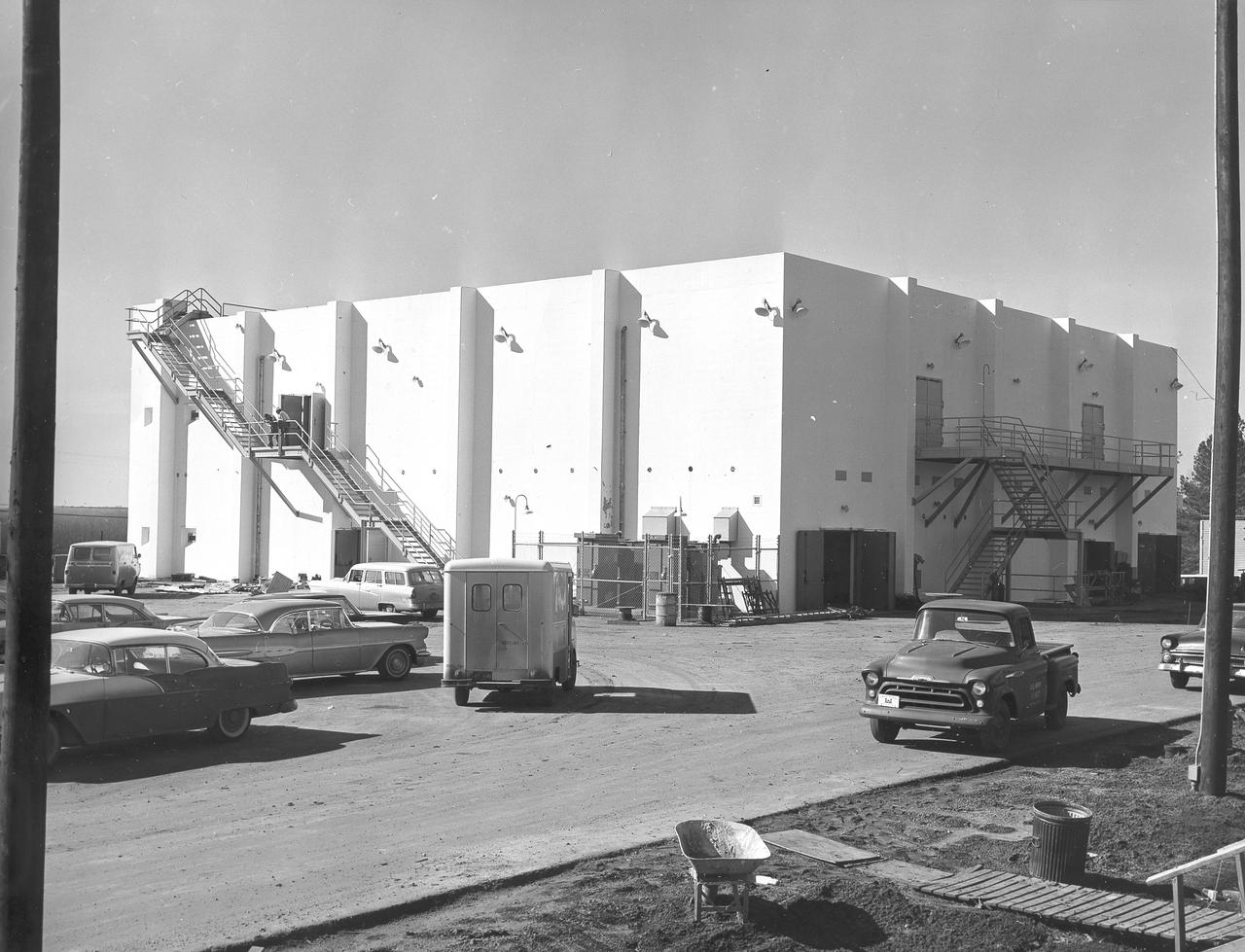
At its founding, the Marshall Space Flight Center (MSFC) inherited the Army’s Jupiter and Redstone test stands, but much larger facilities were needed for the giant stages of the Saturn V. From 1960 to 1964, the existing stands were remodeled and a sizable new test area was developed. The new comprehensive test complex for propulsion and structural dynamics was unique within the nation and the free world, and they remain so today because they were constructed with foresight to meet the future as well as on going needs. Construction of the S-IC Static test stand complex began in 1961 in the west test area of MSFC, and was completed in 1964. The S-IC static test stand was designed to develop and test the 138-ft long and 33-ft diameter Saturn V S-IC first stage, or booster stage, weighing in at 280,000 pounds. Required to hold down the brute force of a 7,500,000-pound thrust produced by 5 F-1 engines, the S-IC static test stand was designed and constructed with the strength of hundreds of tons of steel and 12,000,000 pounds of cement, planted down to bedrock 40 feet below ground level. The foundation walls, constructed with concrete and steel, are 4 feet thick. The base structure consists of four towers with 40-foot-thick walls extending upward 144 feet above ground level. The structure was topped by a crane with a 135-foot boom. With the boom in the upright position, the stand was given an overall height of 405 feet, placing it among the highest structures in Alabama at the time. Built directly east of the test stand was the Block House, which served as the control center for the test stand. The two were connected by a narrow access tunnel which housed the cables for the controls. This construction photo, taken October 8, 1962, depicts a front view of the Block House nearing completion.
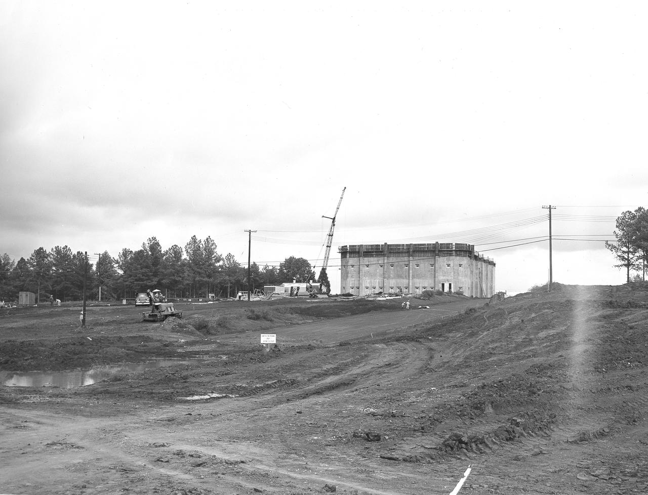
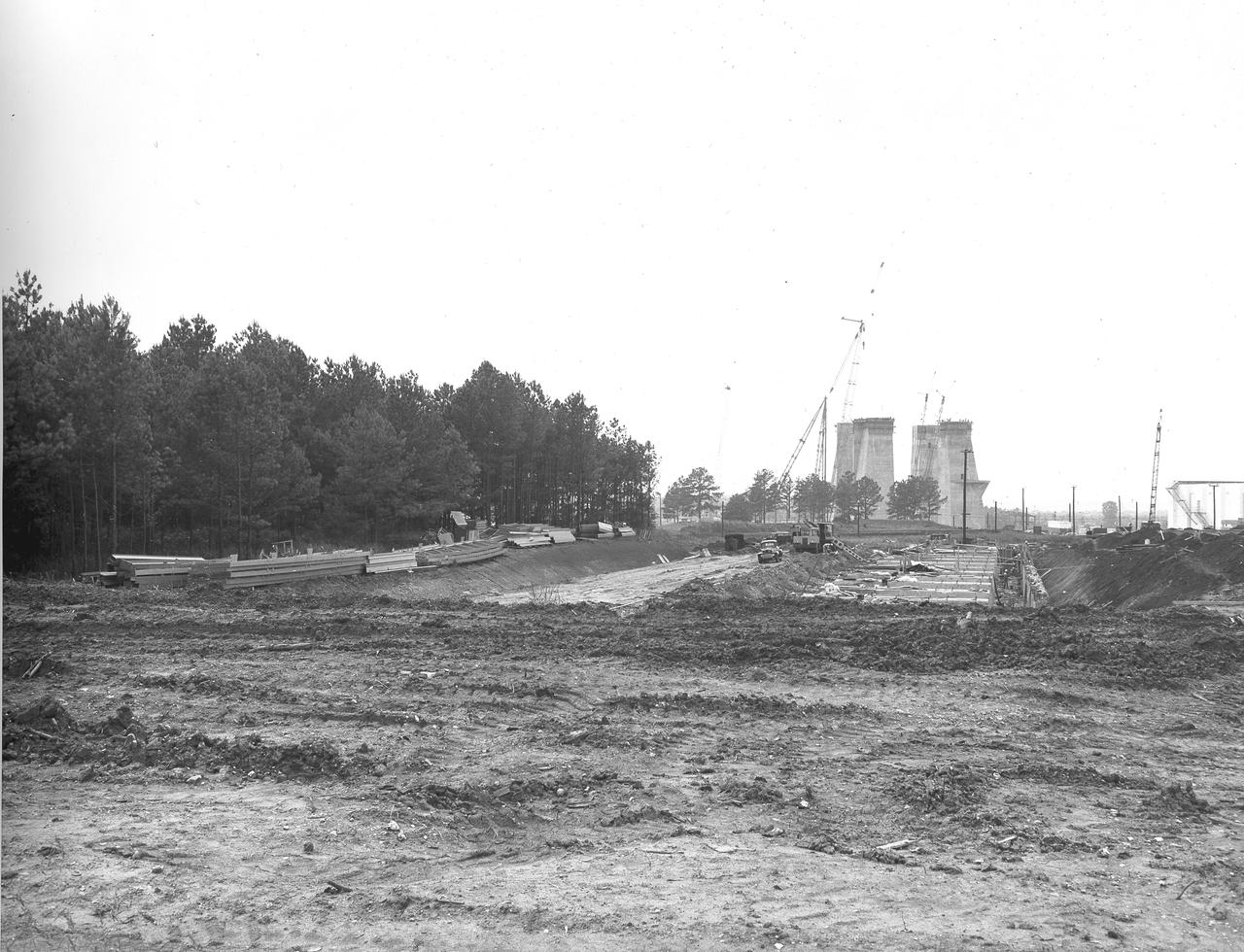
At its founding, the Marshall Space Flight Center (MSFC) inherited the Army’s Jupiter and Redstone test stands, but much larger facilities were needed for the giant stages of the Saturn V. From 1960 to 1964, the existing stands were remodeled and a sizable new test area was developed. The new comprehensive test complex for propulsion and structural dynamics was unique within the nation and the free world, and they remain so today because they were constructed with foresight to meet the future as well as on going needs. Construction of the S-IC Static test stand complex began in 1961 in the west test area of MSFC, and was completed in 1964. The S-IC static test stand was designed to develop and test the 138-ft long and 33-ft diameter Saturn V S-IC first stage, or booster stage, weighing in at 280,000 pounds. Required to hold down the brute force of a 7,500,000-pound thrust produced by 5 F-1 engines, the S-IC static test stand was designed and constructed with the strength of hundreds of tons of steel and 12,000,000 pounds of cement, planted down to bedrock 40 feet below ground level. The foundation walls, constructed with concrete and steel, are 4 feet thick. The base structure consists of four towers with 40-foot-thick walls extending upward 144 feet above ground level. The structure was topped by a crane with a 135-foot boom. With the boom in the upright position, the stand was given an overall height of 405 feet, placing it among the highest structures in Alabama at the time. In addition to the stand itself, related facilities were constructed during this time. Built directly east of the test stand was the Block House, which served as the control center for the test stand. The two were connected by a narrow access tunnel which housed the cables for the controls. This distant construction photo, taken October 26, 1962, depicts a view of the Block House and test stand site.
At its founding, the Marshall Space Flight Center (MSFC) inherited the Army’s Jupiter and Redstone test stands, but much larger facilities were needed for the giant stages of the Saturn V. From 1960 to 1964, the existing stands were remodeled and a sizable new test area was developed. The new comprehensive test complex for propulsion and structural dynamics was unique within the nation and the free world, and they remain so today because they were constructed with foresight to meet the future as well as on going needs. Construction of the S-IC Static test stand complex began in 1961 in the west test area of MSFC, and was completed in 1964. The S-IC static test stand was designed to develop and test the 138-ft long and 33-ft diameter Saturn V S-IC first stage, or booster stage, weighing in at 280,000 pounds. Required to hold down the brute force of a 7,500,000-pound thrust produced by 5 F-1 engines, the S-IC static test stand was designed and constructed with the strength of hundreds of tons of steel and 12,000,000 pounds of cement, planted down to bedrock 40 feet below ground level. The foundation walls, constructed with concrete and steel, are 4 feet thick. The base structure consists of four towers with 40-foot-thick walls extending upward 144 feet above ground level. The structure was topped by a crane with a 135-foot boom. With the boom in the upright position, the stand was given an overall height of 405 feet, placing it among the highest structures in Alabama at the time. In addition to the stand itself, related facilities were constructed during this time. Built directly east of the test stand was the Block House, which served as the control center for the test stand. The two were connected by a narrow access tunnel which housed the cables for the controls. This construction photo taken August 17, 1962 depicts a back side view of the Block House.
At its founding, the Marshall Space Flight Center (MSFC) inherited the Army’s Jupiter and Redstone test stands, but much larger facilities were needed for the giant stages of the Saturn V. From 1960 to 1964, the existing stands were remodeled and a sizable new test area was developed. The new comprehensive test complex for propulsion and structural dynamics was unique within the nation and the free world, and they remain so today because they were constructed with foresight to meet the future as well as on going needs. Construction of the S-IC Static test stand complex began in 1961 in the west test area of MSFC, and was completed in 1964. The S-IC static test stand was designed to develop and test the 138-ft long and 33-ft diameter Saturn V S-IC first stage, or booster stage, weighing in at 280,000 pounds. Required to hold down the brute force of a 7,500,000-pound thrust produced by 5 F-1 engines, the S-IC static test stand was designed and constructed with the strength of hundreds of tons of steel and 12,000,000 pounds of cement, planted down to bedrock 40 feet below ground level. The foundation walls, constructed with concrete and steel, are 4 feet thick. The base structure consists of four towers with 40-foot-thick walls extending upward 144 feet above ground level. The structure was topped by a crane with a 135-foot boom. With the boom in the upright position, the stand was given an overall height of 405 feet, placing it among the highest structures in Alabama at the time. In addition to the stand itself, related facilities were constructed during this time. Built directly east of the test stand was the Block House, which served as the control center for the test stand. The two were connected by a narrow access tunnel which housed the cables for the controls. This construction photo taken July 3, 1962 depicts the Block House with a portion of its concrete walls poured and exposed while many are still in the forms stage.
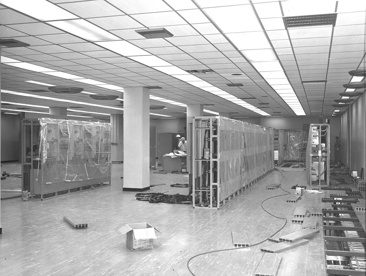
At its founding, the Marshall Space Flight Center (MSFC) inherited the Army’s Jupiter and Redstone test stands, but much larger facilities were needed for the giant stages of the Saturn V. From 1960 to 1964, the existing stands were remodeled and a sizable new test area was developed. The new comprehensive test complex for propulsion and structural dynamics was unique within the nation and the free world, and they remain so today because they were constructed with foresight to meet the future as well as on going needs. Construction of the S-IC Static test stand complex began in 1961 in the west test area of MSFC, and was completed in 1964. The S-IC static test stand was designed to develop and test the 138-ft long and 33-ft diameter Saturn V S-IC first stage, or booster stage, weighing in at 280,000 pounds. Required to hold down the brute force of a 7,500,000-pound thrust produced by 5 F-1 engines, the S-IC static test stand was designed and constructed with the strength of hundreds of tons of steel and 12,000,000 pounds of cement, planted down to bedrock 40 feet below ground level. The foundation walls, constructed with concrete and steel, are 4 feet thick. The base structure consists of four towers with 40-foot-thick walls extending upward 144 feet above ground level. The structure was topped by a crane with a 135-foot boom. With the boom in the upright position, the stand was given an overall height of 405 feet, placing it among the highest structures in Alabama at the time. In addition to the stand itself, related facilities were constructed during this time. Built directly east of the test stand was the Block House, which served as the control center for the test stand. The two were connected by a narrow access tunnel which housed the cables for the controls. This photograph, taken August 12, 1963, offers a view of the Block House interior.
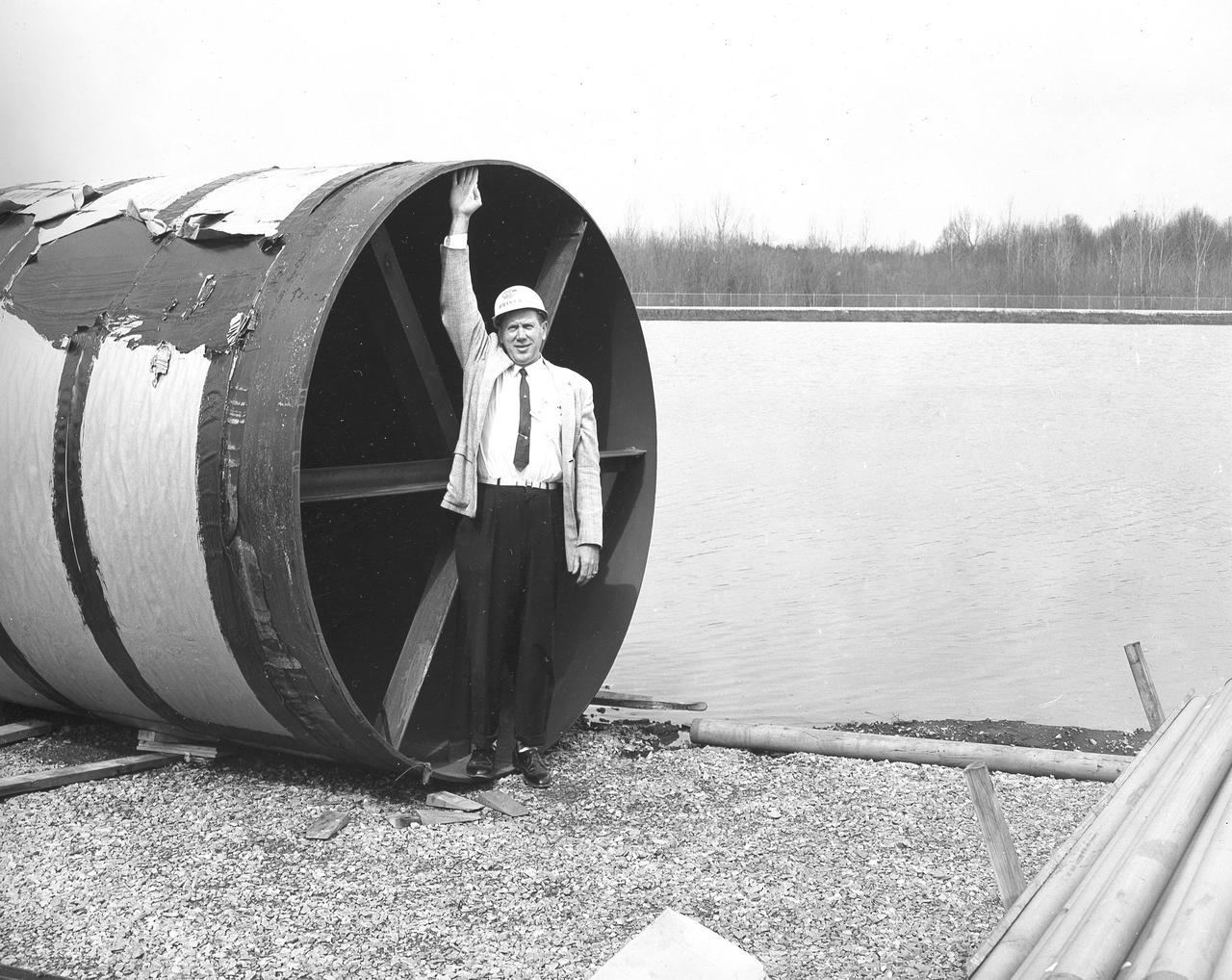
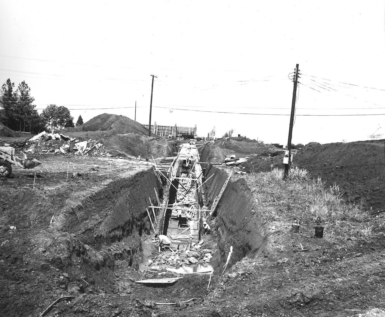
At its founding, the Marshall Space Flight Center (MSFC) inherited the Army’s Jupiter and Redstone test stands, but much larger facilities were needed for the giant stages of the Saturn V. From 1960 to 1964, the existing stands were remodeled and a sizable new test area was developed. The new comprehensive test complex for propulsion and structural dynamics was unique within the nation and the free world, and they remain so today because they were constructed with foresight to meet the future as well as on going needs. Construction of the S-IC Static test stand complex began in 1961 in the west test area of MSFC, and was completed in 1964. The S-IC static test stand was designed to develop and test the 138-ft long and 33-ft diameter Saturn V S-IC first stage, or booster stage, weighing in at 280,000 pounds. Required to hold down the brute force of a 7,500,000-pound thrust produced by 5 F-1 engines, the S-IC static test stand was designed and constructed with the strength of hundreds of tons of steel and 12,000,000 pounds of cement, planted down to bedrock 40 feet below ground level. The foundation walls, constructed with concrete and steel, are 4 feet thick. The base structure consists of four towers with 40-foot-thick walls extending upward 144 feet above ground level. The structure was topped by a crane with a 135-foot boom. With the boom in the upright position, the stand was given an overall height of 405 feet, placing it among the highest structures in Alabama at the time. In addition to the stand itself, related facilities were constructed during this time. Built directly east of the test stand was the Block House, which served as the control center for the test stand. The two were connected by a narrow access tunnel which housed the cables for the controls. Again to the east, just south of the Block House, was a newly constructed Pump House. Its function was to provide water to the stand to prevent melting damage during testing. The water was sprayed through small holes in the stand’s 1900 ton water deflector at the rate of 320,000 gallons per minute. In this photo, NASA employee Orville Driver is demonstrating the size of the 8 foot diameter water lines used for this purpose.
At its founding, the Marshall Space Flight Center (MSFC) inherited the Army’s Jupiter and Redstone test stands, but much larger facilities were needed for the giant stages of the Saturn V. From 1960 to 1964, the existing stands were remodeled and a sizable new test area was developed. The new comprehensive test complex for propulsion and structural dynamics was unique within the nation and the free world, and they remain so today because they were constructed with foresight to meet the future as well as on going needs. Construction of the S-IC Static test stand complex began in 1961 in the west test area of MSFC, and was completed in 1964. The S-IC static test stand was designed to develop and test the 138-ft long and 33-ft diameter Saturn V S-IC first stage, or booster stage, weighing in at 280,000 pounds. Required to hold down the brute force of a 7,500,000-pound thrust produced by 5 F-1 engines, the S-IC static test stand was designed and constructed with the strength of hundreds of tons of steel and 12,000,000 pounds of cement, planted down to bedrock 40 feet below ground level. The foundation walls, constructed with concrete and steel, are 4 feet thick. The base structure consists of four towers with 40-foot-thick walls extending upward 144 feet above ground level. The structure was topped by a crane with a 135-foot boom. With the boom in the upright position, the stand was given an overall height of 405 feet, placing it among the highest structures in Alabama at the time. In addition to the stand itself, related facilities were constructed during this time. Built directly east of the test stand was the Block House, which served as the control center for the test stand. The two were connected by a narrow access tunnel which housed the cables for the controls. This construction photo taken August 17, 1962 depicts a view of the Block House from the test stand site. The tunnel opening is visible in the forefront center of the photo.
At its founding, the Marshall Space Flight Center (MSFC) inherited the Army’s Jupiter and Redstone test stands, but much larger facilities were needed for the giant stages of the Saturn V. From 1960 to 1964, the existing stands were remodeled and a sizable new test area was developed. The new comprehensive test complex for propulsion and structural dynamics was unique within the nation and the free world, and they remain so today because they were constructed with foresight to meet the future as well as on going needs. Construction of the S-IC Static test stand complex began in 1961 in the west test area of MSFC, and was completed in 1964. The S-IC static test stand was designed to develop and test the 138-ft long and 33-ft diameter Saturn V S-IC first stage, or booster stage, weighing in at 280,000 pounds. Required to hold down the brute force of a 7,500,000-pound thrust produced by 5 F-1 engines, the S-IC static test stand was designed and constructed with the strength of hundreds of tons of steel and 12,000,000 pounds of cement, planted down to bedrock 40 feet below ground level. The foundation walls, constructed with concrete and steel, are 4 feet thick. The base structure consists of four towers with 40-foot-thick walls extending upward 144 feet above ground level. The structure was topped by a crane with a 135-foot boom. With the boom in the upright position, the stand was given an overall height of 405 feet, placing it among the highest structures in Alabama at the time. In addition to the stand itself, related facilities were constructed during this time. Built directly east of the test stand was the Block House, which served as the control center for the test stand. The two were connected by a narrow access tunnel which housed the cables for the controls. This construction photo, taken October 26, 1962, depicts a view of the Block House tunnel opening.
At its founding, the Marshall Space Flight Center (MSFC) inherited the Army’s Jupiter and Redstone test stands, but much larger facilities were needed for the giant stages of the Saturn V. From 1960 to 1964, the existing stands were remodeled and a sizable new test area was developed. The new comprehensive test complex for propulsion and structural dynamics was unique within the nation and the free world, and they remain so today because they were constructed with foresight to meet the future as well as on going needs. Construction of the S-IC Static test stand complex began in 1961 in the west test area of MSFC, and was completed in 1964. The S-IC static test stand was designed to develop and test the 138-ft long and 33-ft diameter Saturn V S-IC first stage, or booster stage, weighing in at 280,000 pounds. Required to hold down the brute force of a 7,500,000-pound thrust produced by 5 F-1 engines, the S-IC static test stand was designed and constructed with the strength of hundreds of tons of steel and 12,000,000 pounds of cement, planted down to bedrock 40 feet below ground level. The foundation walls, constructed with concrete and steel, are 4 feet thick. The base structure consists of four towers with 40-foot-thick walls extending upward 144 feet above ground level. The structure was topped by a crane with a 135-foot boom. With the boom in the upright position, the stand was given an overall height of 405 feet, placing it among the highest structures in Alabama at the time. In addition to the stand itself, related facilities were constructed during this time. Built directly east of the test stand was the Block House, which served as the control center for the test stand. The two were connected by a narrow tunnel which housed the cables for the controls. This photograph, taken on May 21, 1962 depicts the access tunnel construction.
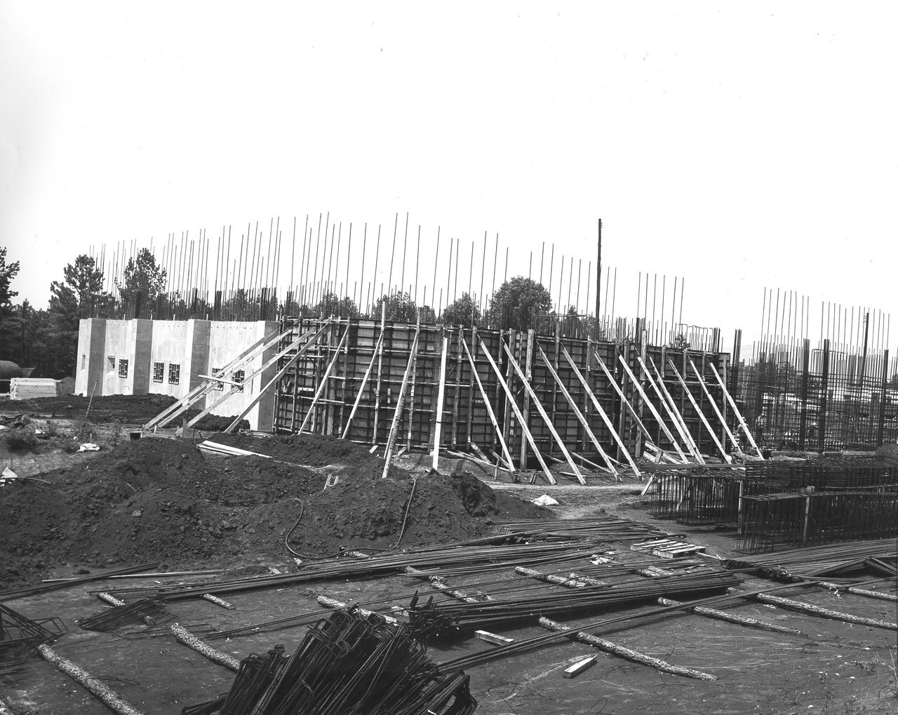
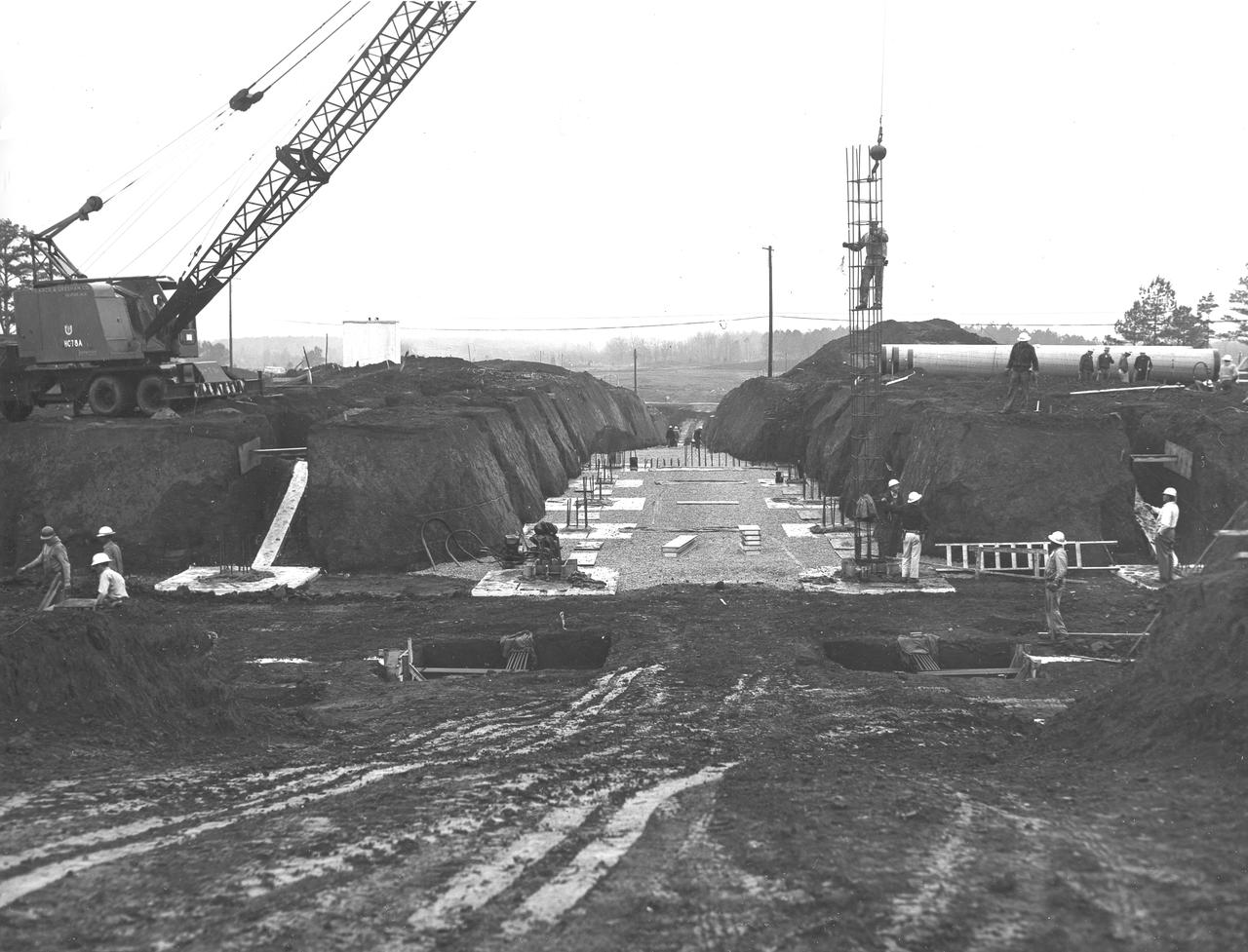
At its founding, the Marshall Space Flight Center (MSFC) inherited the Army’s Jupiter and Redstone test stands, but much larger facilities were needed for the giant stages of the Saturn V. From 1960 to 1964, the existing stands were remodeled and a sizable new test area was developed. The new comprehensive test complex for propulsion and structural dynamics was unique within the nation and the free world, and they remain so today because they were constructed with foresight to meet the future as well as on going needs. Construction of the S-IC Static test stand complex began in 1961 in the west test area of MSFC, and was completed in 1964. The S-IC static test stand was designed to develop and test the 138-ft long and 33-ft diameter Saturn V S-IC first stage, or booster stage, weighing in at 280,000 pounds. Required to hold down the brute force of a 7,500,000-pound thrust produced by 5 F-1 engines, the S-IC static test stand was designed and constructed with the strength of hundreds of tons of steel and 12,000,000 pounds of cement, planted down to bedrock 40 feet below ground level. The foundation walls, constructed with concrete and steel, are 4 feet thick. The base structure consists of four towers with 40-foot-thick walls extending upward 144 feet above ground level. The structure was topped by a crane with a 135-foot boom. With the boom in the upright position, the stand was given an overall height of 405 feet, placing it among the highest structures in Alabama at the time. In addition to the stand itself, related facilities were constructed during this time. Built directly east of the test stand was the Block House, which served as the control center for the test stand. The two were connected by a narrow access tunnel which housed the cables for the controls. Construction of the tunnel is depicted in this photo taken June 13, 1962.
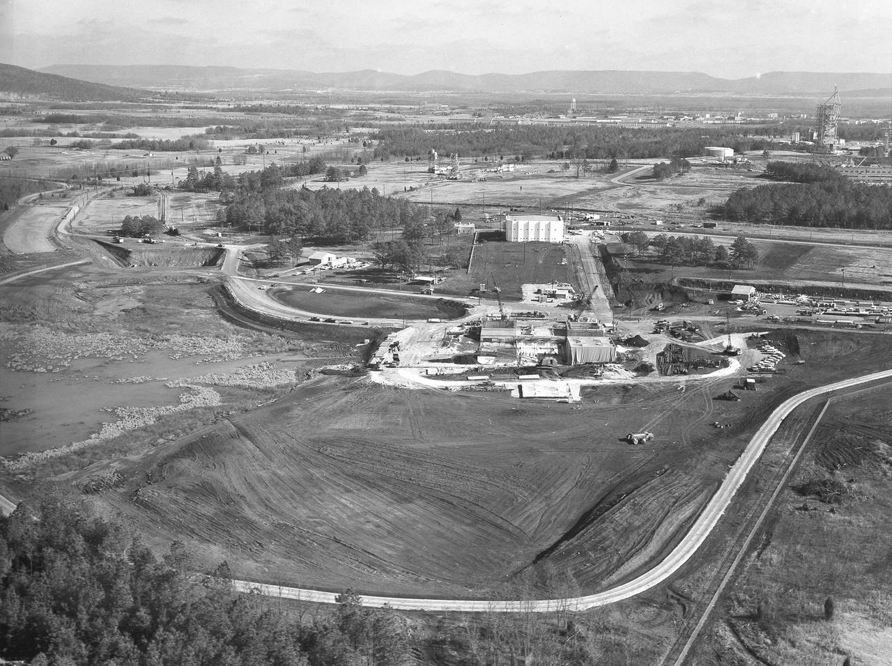
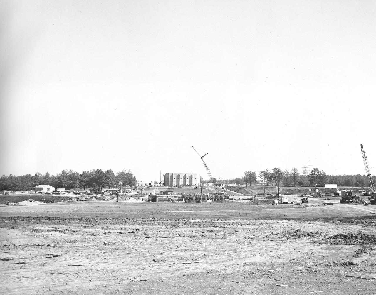
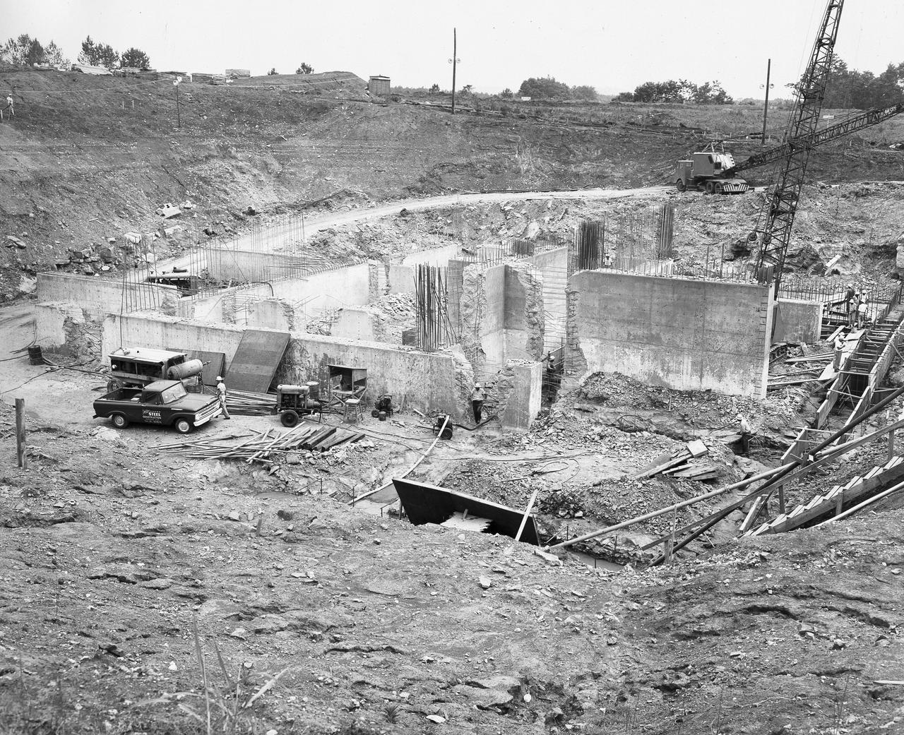
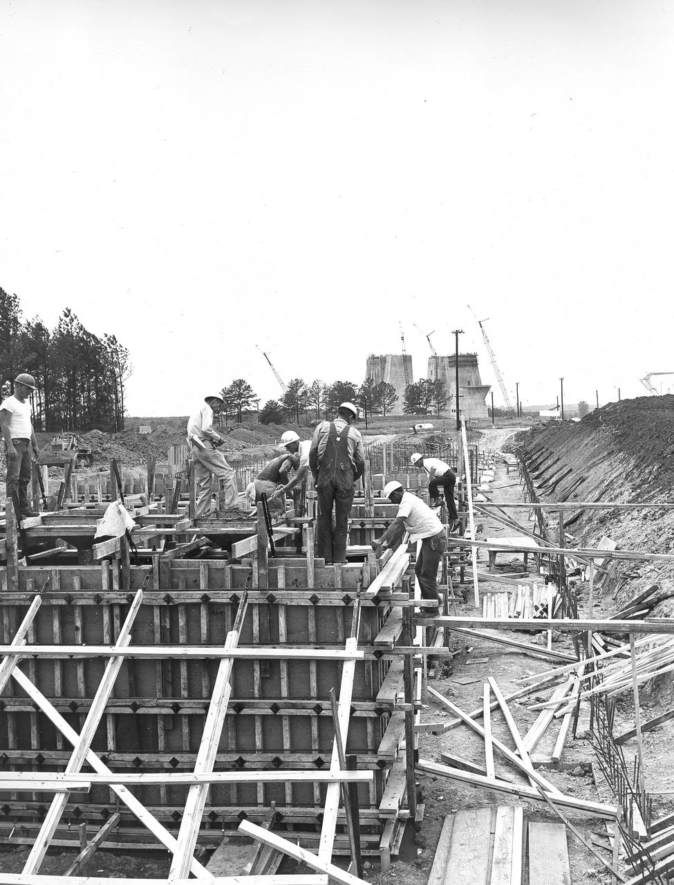
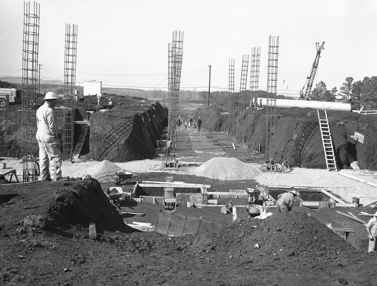
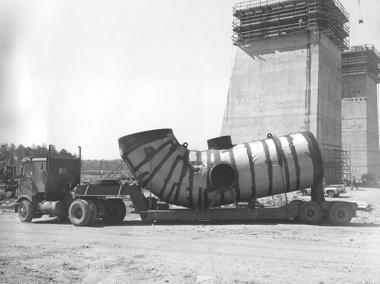
At its founding, the Marshall Space Flight Center (MSFC) inherited the Army’s Jupiter and Redstone test stands, but much larger facilities were needed for the giant stages of the Saturn V. From 1960 to 1964, the existing stands were remodeled and a sizable new test area was developed. The new comprehensive test complex for propulsion and structural dynamics was unique within the nation and the free world, and they remain so today because they were constructed with foresight to meet the future as well as on going needs. Construction of the S-IC Static test stand complex began in 1961 in the west test area of MSFC, and was completed in 1964. The S-IC static test stand was designed to develop and test the 138-ft long and 33-ft diameter Saturn V S-IC first stage, or booster stage, weighing in at 280,000 pounds. Required to hold down the brute force of a 7,500,000-pound thrust produced by 5 F-1 engines, the S-IC static test stand was designed and constructed with the strength of hundreds of tons of steel and 12,000,000 pounds of cement, planted down to bedrock 40 feet below ground level. The foundation walls, constructed with concrete and steel, are 4 feet thick. The base structure consists of four towers with 40-foot-thick walls extending upward 144 feet above ground level. The structure was topped by a crane with a 135-foot boom. With the boom in the upright position, the stand was given an overall height of 405 feet, placing it among the highest structures in Alabama at the time. In addition to the stand itself, related facilities were constructed during this time. Built directly east of the test stand was the Block House, which served as the control center for the test stand. The two were connected by a narrow access tunnel which housed the cables for the controls. The F-1 Engine test stand was built north of the massive S-IC test stand. The F-1 test stand is a vertical engine firing test stand, 239 feet in elevation and 4,600 square feet in area at the base, and was designed to assist in the development of the F-1 Engine. Capability is provided for static firing of 1.5 million pounds of thrust using liquid oxygen and kerosene. Like the S-IC stand, the foundation of the F-1 stand is keyed into the bedrock approximately 40 feet below grade. This aerial photograph, taken January 15, 1963, gives a close overall view of the newly developed test complex. Depicted in the forefront center is the S-IC test stand with towers prominent, the Block House is seen in the center just above the S-IC test stand, and the large hole to the left, located midway between the two is the F-1 test stand site.
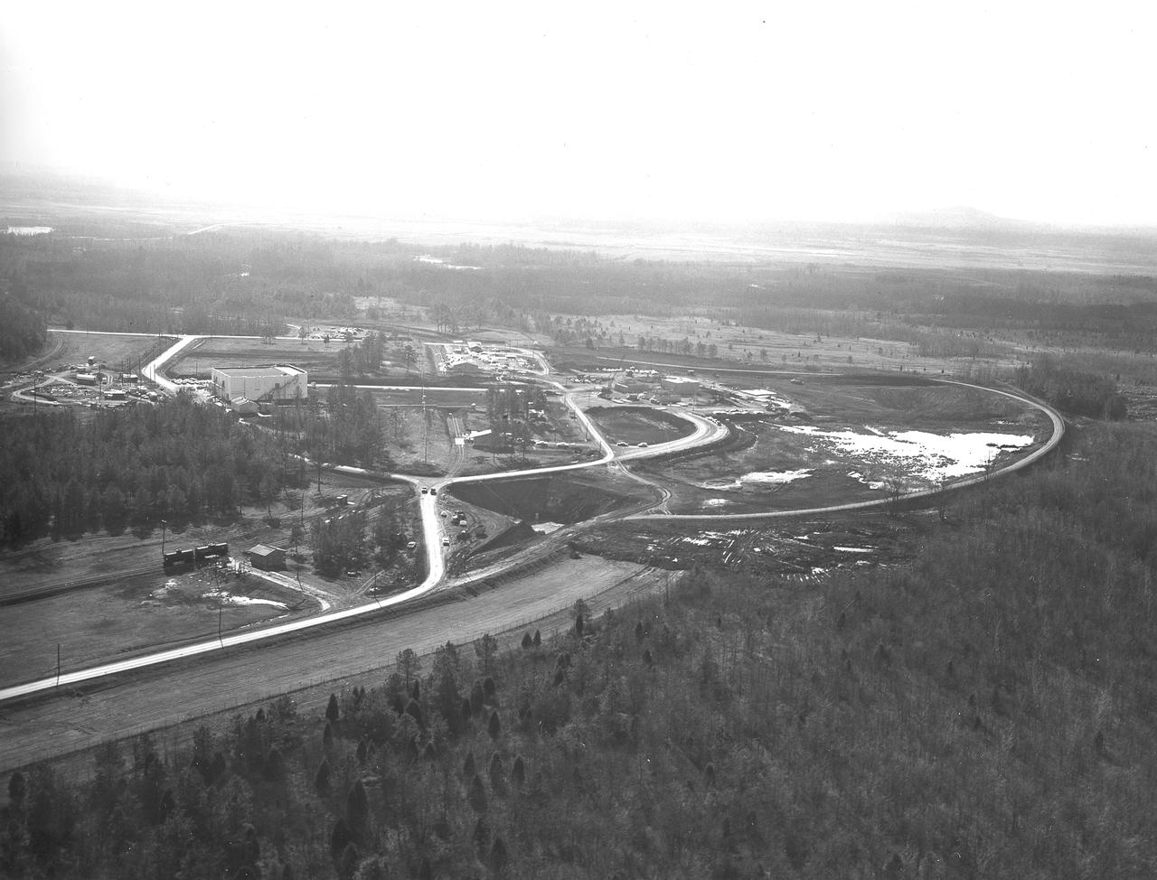
At its founding, the Marshall Space Flight Center (MSFC) inherited the Army’s Jupiter and Redstone test stands, but much larger facilities were needed for the giant stages of the Saturn V. From 1960 to 1964, the existing stands were remodeled and a sizable new test area was developed. The new comprehensive test complex for propulsion and structural dynamics was unique within the nation and the free world, and they remain so today because they were constructed with foresight to meet the future as well as on going needs. Construction of the S-IC Static test stand complex began in 1961 in the west test area of MSFC, and was completed in 1964. The S-IC static test stand was designed to develop and test the 138-ft long and 33-ft diameter Saturn V S-IC first stage, or booster stage, weighing in at 280,000 pounds. Required to hold down the brute force of a 7,500,000-pound thrust produced by 5 F-1 engines, the S-IC static test stand was designed and constructed with the strength of hundreds of tons of steel and 12,000,000 pounds of cement, planted down to bedrock 40 feet below ground level. The foundation walls, constructed with concrete and steel, are 4 feet thick. The base structure consists of four towers with 40-foot-thick walls extending upward 144 feet above ground level. The structure was topped by a crane with a 135-foot boom. With the boom in the upright position, the stand was given an overall height of 405 feet, placing it among the highest structures in Alabama at the time. In addition to the stand itself, related facilities were constructed during this time. Built directly east of the test stand was the Block House, which served as the control center for the test stand. The two were connected by a narrow access tunnel which housed the cables for the controls. The F-1 Engine test stand was built north of the massive S-IC test stand. The F-1 test stand is a vertical engine firing test stand, 239 feet in elevation and 4,600 square feet in area at the base, and was designed to assist in the development of the F-1 Engine. Capability is provided for static firing of 1.5 million pounds of thrust using liquid oxygen and kerosene. Like the S-IC stand, the foundation of the F-1 stand is keyed into the bedrock approximately 40 feet below grade. Looking North, this aerial taken January 15, 1963, gives a closer view of the deep hole for the F-1 test stand site in the forefront. The S-IC test stand with towers prominent is to the right of center, and the Block House is seen left of center.
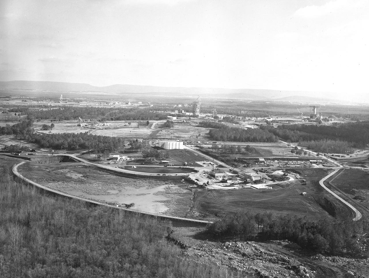
At its founding, the Marshall Space Flight Center (MSFC) inherited the Army’s Jupiter and Redstone test stands, but much larger facilities were needed for the giant stages of the Saturn V. From 1960 to 1964, the existing stands were remodeled and a sizable new test area was developed. The new comprehensive test complex for propulsion and structural dynamics was unique within the nation and the free world, and they remain so today because they were constructed with foresight to meet the future as well as on going needs. Construction of the S-IC Static test stand complex began in 1961 in the west test area of MSFC, and was completed in 1964. The S-IC static test stand was designed to develop and test the 138-ft long and 33-ft diameter Saturn V S-IC first stage, or booster stage, weighing in at 280,000 pounds. Required to hold down the brute force of a 7,500,000-pound thrust produced by 5 F-1 engines, the S-IC static test stand was designed and constructed with the strength of hundreds of tons of steel and 12,000,000 pounds of cement, planted down to bedrock 40 feet below ground level. The foundation walls, constructed with concrete and steel, are 4 feet thick. The base structure consists of four towers with 40-foot-thick walls extending upward 144 feet above ground level. The structure was topped by a crane with a 135-foot boom. With the boom in the upright position, the stand was given an overall height of 405 feet, placing it among the highest structures in Alabama at the time. In addition to the stand itself, related facilities were constructed during this time. Built directly east of the test stand was the Block House, which served as the control center for the test stand. The two were connected by a narrow access tunnel which housed the cables for the controls. The F-1 Engine test stand was built north of the massive S-IC test stand. The F-1 test stand is a vertical engine firing test stand, 239 feet in elevation and 4,600 square feet in area at the base, and was designed to assist in the development of the F-1 Engine. Capability is provided for static firing of 1.5 million pounds of thrust using liquid oxygen and kerosene. Like the S-IC stand, the foundation of the F-1 stand is keyed into the bedrock approximately 40 feet below grade. This aerial photograph, taken January 15, 1963 gives an overall view of the construction progress of the newly developed test complex. The large white building located in the center is the Block House. Just below and to the right of it is the S-IC test stand. The large hole to the left of the S-IC stand is the F-1 test stand site.
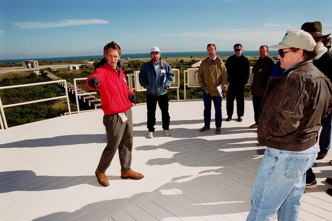
On top of the block house at Launch Complex 34, representatives from environmental and Federal agencies hear from Laymon Gray, with Florida State University, about the environmental research project that involves the Department of Defense, Environmental Protection Agency, Department of Energy and NASA in a groundwater cleanup effort. Concentrations of trichloroethylene solvent have been identified in the soil at the complex as a result of cleaning methods for rocket parts during the Apollo Program, which used the complex, in the 60s. The group formed the Interagency NDAPL Consortium (IDC) to study three contamination cleanup technologies: Six Phase Soil Heating, Steam Injection and In Situ Oxidation with Potassium Permanganate. All three methods may offer a way to remove the contaminants in months instead of decades. In the background (left) can be seen the cement platform and walkway from the block house to the pad. Beyond it is the Atlantic Ocean. KSC hosted a two-day conference that presented information and demonstrations of the three technologies being tested at the site

On top of the block house at Launch Complex 34, representatives from environmental and Federal agencies hear from Laymon Gray, with Florida State University, about the environmental research project that involves the Department of Defense, Environmental Protection Agency, Department of Energy and NASA in a groundwater cleanup effort. Concentrations of trichloroethylene solvent have been identified in the soil at the complex as a result of cleaning methods for rocket parts during the Apollo Program, which used the complex, in the 60s. The group formed the Interagency NDAPL Consortium (IDC) to study three contamination cleanup technologies: Six Phase Soil Heating, Steam Injection and In Situ Oxidation with Potassium Permanganate. All three methods may offer a way to remove the contaminants in months instead of decades. In the background (left) can be seen the cement platform and walkway from the block house to the pad. Beyond it is the Atlantic Ocean. KSC hosted a two-day conference that presented information and demonstrations of the three technologies being tested at the site
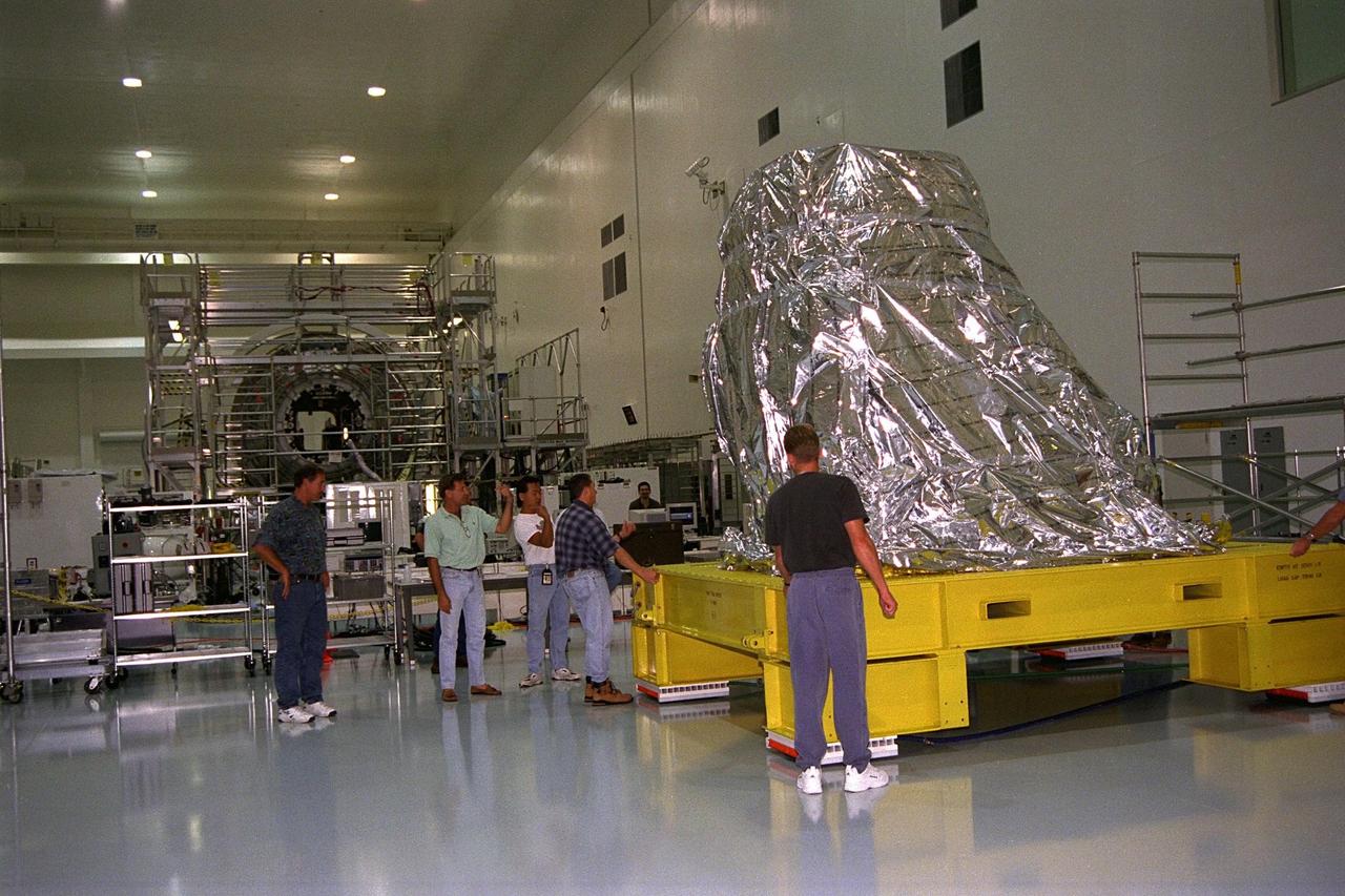
The first of two Pressurized Mating Adapters, or PMAs, for the International Space Station arrive in KSC’s Space Station Processing Facility in July. A PMA is a cone-shaped connector that will be attached to Node 1, the space station’s structural building block, during ground processing. The adapter will house space station computers and various electrical support equipment and eventually will serve as the passageway for astronauts between the node and the U.S-financed, Russian-built Functional Cargo Block. Node 1 with two adapters attached will be the first element of the station to be launched aboard the Space Shuttle Endeavour on STS-88 in July 1998

The first of two Pressurized Mating Adapters, or PMAs, for the International Space Station arrive in KSC’s Space Station Processing Facility in July. A PMA is a cone-shaped connector that will be attached to Node 1, the space station’s structural building block, during ground processing. The adapter will house space station computers and various electrical support equipment and eventually will serve as the passageway for astronauts between the node and the U.S-financed, Russian-built Functional Cargo Block. Node 1 with two adapters attached will be the first element of the station to be launched aboard the Space Shuttle Endeavour on STS-88 in July 1998
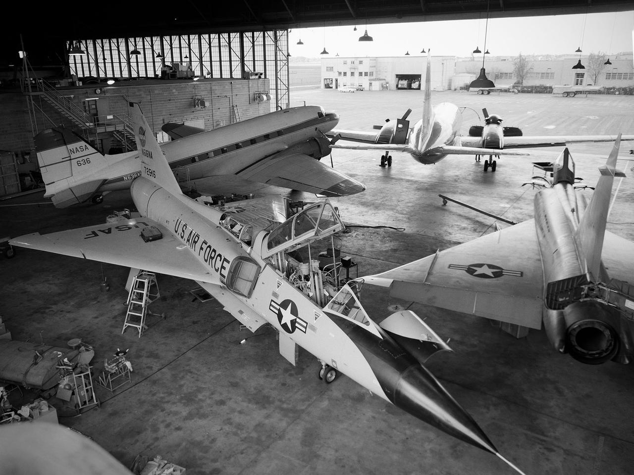
Several aircraft parked inside the Flight Research Building, or hangar, at the National Aeronautics and Space Administration (NASA) Lewis Research Center in Cleveland, Ohio. A Convair F-106B Delta Dart is in the foreground, a Convair F-102A Delta Dagger is to the right, a Douglas DC-3 is in the back to left, and a Convair T-29 is in background. Lewis’ Martin B-57B Canberra is not seen in this photograph. The F-102A had just been acquired by Lewis to serve as a chase plane for the F-106B. The Lewis team removed the weapons system and 700 pounds of wire from the F-106B when it was acquired on October 20, 1966. The staff cut holes in the wings and modified the elevons to mount the test nacelles. A 228-gallon fuel tank was installed in the missile bay, and the existing wing tanks were used for instrumentation. This photograph contains a rare view of the Block House, seen to the left of the aircraft. Lewis acquired three large developmental programs in 1962—the Centaur and Agena rockets and the M-1 engine. The center was short on office space at the time, and its flight research program was temporarily on the wane. Lewis management decided to construct a large cinderblock structure inside one half of the hangar to house the new personnel. This structure was used until 1965 when the new Developmental Engineering Building was built. The Block House was eventually torn down in 1973.
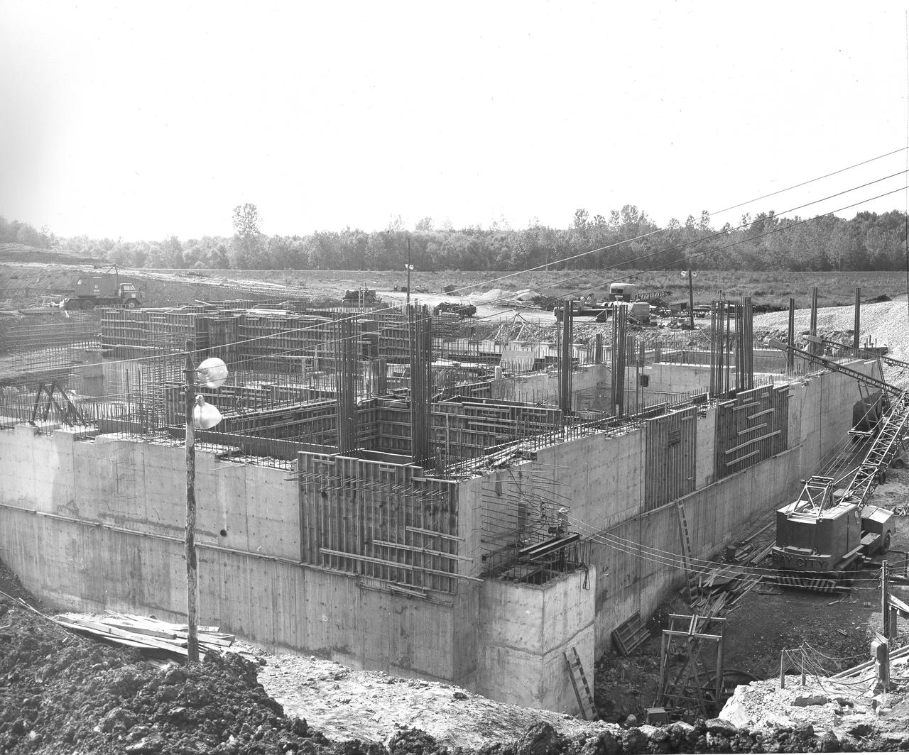
At its founding, the Marshall Space Flight Center (MSFC) inherited the Army’s Jupiter and Redstone test stands, but much larger facilities were needed for the giant stages of the Saturn V. From 1960 to 1964, the existing stands were remodeled and a sizable new test area was developed. The new comprehensive test complex for propulsion and structural dynamics was unique within the nation and the free world, and they remain so today because they were constructed with foresight to meet the future as well as on going needs. Construction of the S-IC Static test stand complex began in 1961 in the west test area of MSFC, and was completed in 1964. The S-IC static test stand was designed to develop and test the 138-ft long and 33-ft diameter Saturn V S-IC first stage, or booster stage, weighing in at 280,000 pounds. Required to hold down the brute force of a 7,500,000-pound thrust produced by 5 F-1 engines, the S-IC static test stand was designed and constructed with the strength of hundreds of tons of steel and 12,000,000 pounds of cement, planted down to bedrock 40 feet below ground level. The foundation walls, constructed with concrete and steel, are 4 feet thick. The base structure consists of four towers with 40-foot-thick walls extending upward 144 feet above ground level. The structure was topped by a crane with a 135-foot boom. With the boom in the upright position, the stand was given an overall height of 405 feet, placing it among the highest structures in Alabama at the time. After a 6 month delay in construction due to size reconfiguration of the Saturn booster, the site was revisited for modifications. The original foundation walls built in the prior year had to be torn down and re-poured to accommodate the larger booster. The demolition can be seen in this photograph taken on May 21, 1962.
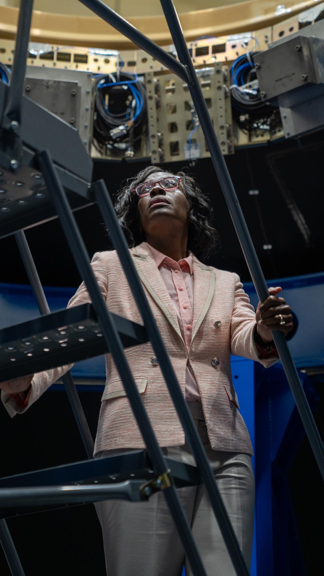
Lakiesha Hawkins, Assistant Deputy Associate Administrator for the Moon to Mars (M2M) Program within the Exploration Systems Development Mission Directorate (ESDMD), takes a peek at the Payload Adapter test article at Marshall Space Flight Center. The adapter, which will debut on NASA’s Artemis IV mission, is an evolution from the Orion stage adapter used in the Block 1 configuration of the rocket for the first three Artemis missions. It will be housed inside the universal stage adapter atop the rocket’s more powerful in-space stage, called the exploration upper stage. The payload adapter, like the launch vehicle stage adapter and the Orion stage adapter, is fully manufactured and tested at Marshall, which manages the SLS Program.
At its founding, the Marshall Space Flight Center (MSFC) inherited the Army’s Jupiter and Redstone test stands, but much larger facilities were needed for the giant stages of the Saturn V. From 1960 to 1964, the existing stands were remodeled and a sizable new test area was developed. The new comprehensive test complex for propulsion and structural dynamics was unique within the nation and the free world, and they remain so today because they were constructed with foresight to meet the future as well as on going needs. Construction of the S-IC Static test stand complex began in 1961 in the west test area of MSFC, and was completed in 1964. The S-IC static test stand was designed to develop and test the 138-ft long and 33-ft diameter Saturn V S-IC first stage, or booster stage, weighing in at 280,000 pounds. Required to hold down the brute force of a 7,500,000-pound thrust produced by 5 F-1 engines, the S-IC static test stand was designed and constructed with the strength of hundreds of tons of steel and 12,000,000 pounds of cement, planted down to bedrock 40 feet below ground level. The foundation walls, constructed with concrete and steel, are 4 feet thick. The base structure consists of four towers with 40-foot-thick walls extending upward 144 feet above ground level. The structure was topped by a crane with a 135-foot boom. With the boom in the upright position, the stand was given an overall height of 405 feet, placing it among the highest structures in Alabama at the time. In addition to the stand itself, related facilities were constructed during this time. Built directly east of the test stand was the Block House, which served as the control center for the test stand. The two were connected by a narrow access tunnel which housed the cables for the controls. Again to the east, just south of the Block House, was a newly constructed Pump House. Its function was to provide water to the stand to prevent melting damage during testing. The water was sprayed through small holes in the stand’s 1900 ton water deflector at the rate of 320,000 gallons per minute. In this photo, taken May 22, 1963, the Pump House is undergoing construction.
At its founding, the Marshall Space Flight Center (MSFC) inherited the Army’s Jupiter and Redstone test stands, but much larger facilities were needed for the giant stages of the Saturn V. From 1960 to 1964, the existing stands were remodeled and a sizable new test area was developed. The new comprehensive test complex for propulsion and structural dynamics was unique within the nation and the free world, and they remain so today because they were constructed with foresight to meet the future as well as on going needs. Construction of the S-IC Static test stand complex began in 1961 in the west test area of MSFC, and was completed in 1964. The S-IC static test stand was designed to develop and test the 138-ft long and 33-ft diameter Saturn V S-IC first stage, or booster stage, weighing in at 280,000 pounds. Required to hold down the brute force of a 7,500,000-pound thrust produced by 5 F-1 engines, the S-IC static test stand was designed and constructed with the strength of hundreds of tons of steel and 12,000,000 pounds of cement, planted down to bedrock 40 feet below ground level. The foundation walls, constructed with concrete and steel, are 4 feet thick. The base structure consists of four towers with 40-foot-thick walls extending upward 144 feet above ground level. The structure was topped by a crane with a 135-foot boom. With the boom in the upright position, the stand was given an overall height of 405 feet, placing it among the highest structures in Alabama at the time. In addition to the stand itself, related facilities were constructed during this time. Built directly east of the test stand was the Block House, which served as the control center for the test stand. The two were connected by a narrow tunnel which housed the cables for the controls. Again to the east, just south of the Block House, was a newly constructed Pump House. Its function was to provide water to the stand to prevent melting damage during testing. The water was sprayed through small holes in the stand’s 1900 ton water deflector at the rate of 320,000 gallons per minute. In this photo, taken March 20, 1962, construction of the Pump House area is well underway.
At its founding, the Marshall Space Flight Center (MSFC) inherited the Army’s Jupiter and Redstone test stands, but much larger facilities were needed for the giant stages of the Saturn V. From 1960 to 1964, the existing stands were remodeled and a sizable new test area was developed. The new comprehensive test complex for propulsion and structural dynamics was unique within the nation and the free world, and they remain so today because they were constructed with foresight to meet the future as well as on going needs. Construction of the S-IC Static test stand complex began in 1961 in the west test area of MSFC, and was completed in 1964. The S-IC static test stand was designed to develop and test the 138-ft long and 33-ft diameter Saturn V S-IC first stage, or booster stage, weighing in at 280,000 pounds. Required to hold down the brute force of a 7,500,000-pound thrust produced by 5 F-1 engines, the S-IC static test stand was designed and constructed with the strength of hundreds of tons of steel and 12,000,000 pounds of cement, planted down to bedrock 40 feet below ground level. The foundation walls, constructed with concrete and steel, are 4 feet thick. The base structure consists of four towers with 40-foot-thick walls extending upward 144 feet above ground level. The structure was topped by a crane with a 135-foot boom. With the boom in the upright position, the stand was given an overall height of 405 feet, placing it among the highest structures in Alabama at the time. In addition to the stand itself, related facilities were constructed during this time. Built directly east of the test stand was the Block House, which served as the control center for the test stand. The two were connected by a narrow access tunnel which housed the cables for the controls. Again to the east, just south of the Block House, was a newly constructed Pump House. Its function was to provide water to the stand to prevent melting damage during testing. The water was sprayed through small holes in the stand’s 1900 ton water deflector at the rate of 320,000 gallons per minute. In this photo, taken May 22, 1963, the Pump House is undergoing construction.
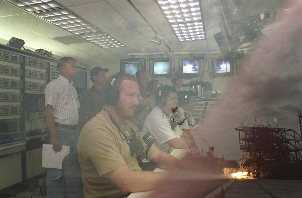
This double exposure depicts Marshall Space Flight Center's (MSFC) Test Stand 116 hosting a 60K Bantam Fastrac thrust chamber assembly test. The lower right exposure shows the engine firing in the test stand while the center exposure reveals workers monitoring the test in the interior block house of the test facility. The thrust chamber assembly is only part of the Fastrac engine project to build a low-cost engine for the X-34, an alternate light-weight unmarned launch vehicle. Both the nozzle and the engine for Fastrac are being manufactured at MSFC.
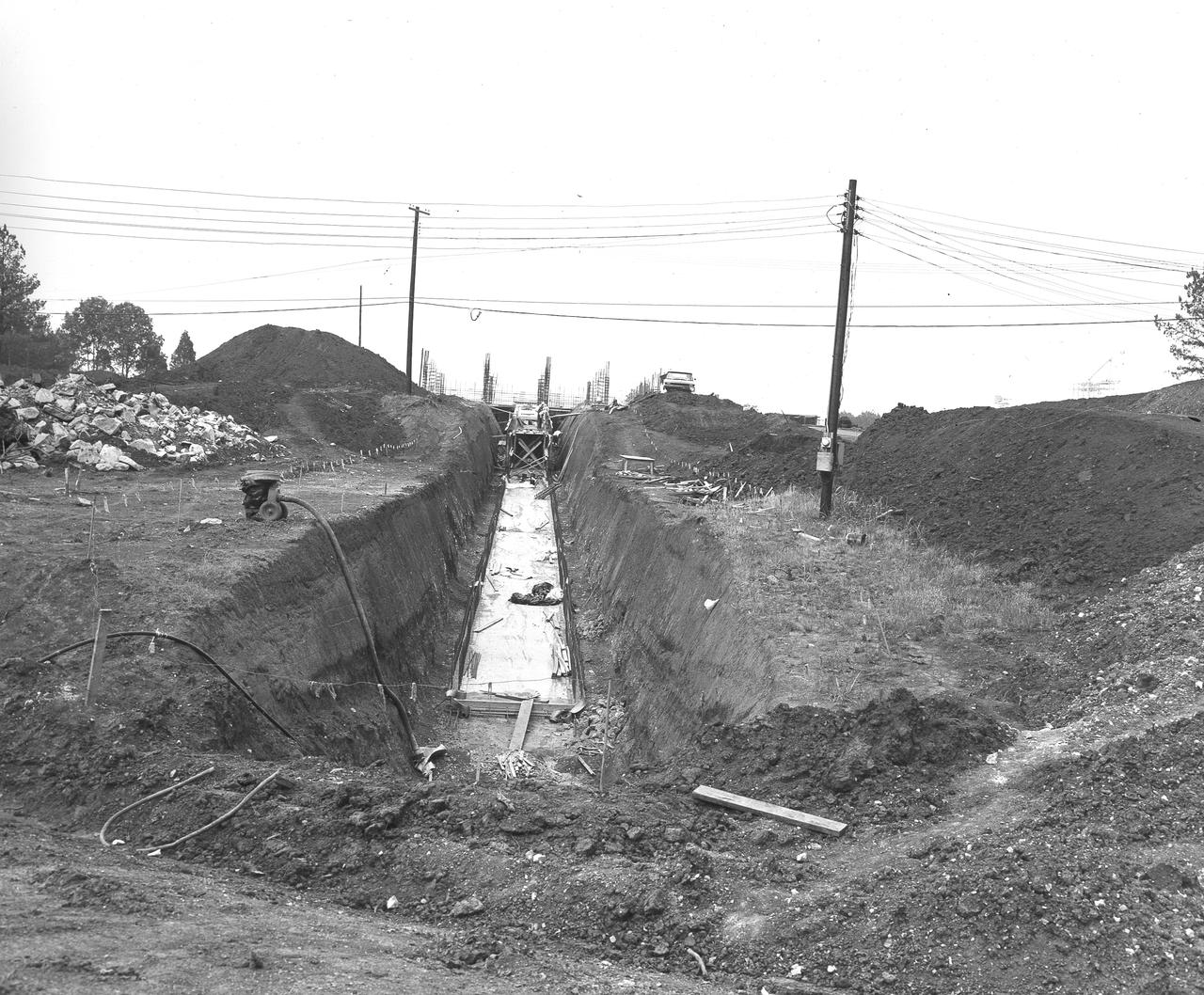
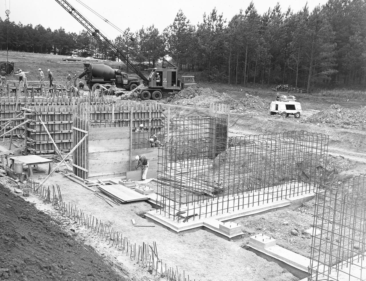
At its founding, the Marshall Space Flight Center (MSFC) inherited the Army’s Jupiter and Redstone test stands, but much larger facilities were needed for the giant stages of the Saturn V. From 1960 to 1964, the existing stands were remodeled and a sizable new test area was developed. The new comprehensive test complex for propulsion and structural dynamics was unique within the nation and the free world, and they remain so today because they were constructed with foresight to meet the future as well as on going needs. Construction of the S-IC Static test stand complex began in 1961 in the west test area of MSFC, and was completed in 1964. The S-IC static test stand was designed to develop and test the 138-ft long and 33-ft diameter Saturn V S-IC first stage, or booster stage, weighing in at 280,000 pounds. Required to hold down the brute force of a 7,500,000-pound thrust produced by 5 F-1 engines, the S-IC static test stand was designed and constructed with the strength of hundreds of tons of steel and 12,000,000 pounds of cement, planted down to bedrock 40 feet below ground level. The foundation walls, constructed with concrete and steel, are 4 feet thick. The base structure consists of four towers with 40-foot-thick walls extending upward 144 feet above ground level. The structure was topped by a crane with a 135-foot boom. With the boom in the upright position, the stand was given an overall height of 405 feet, placing it among the highest structures in Alabama at the time. In addition to the stand itself, related facilities were constructed during this time. Built directly east of the test stand was the Block House, which served as the control center for the test stand. The two were connected by a narrow tunnel which housed the cables for the controls. Again to the east, just south of the Block House, was a newly constructed Pump House. Its function was to provide water to the stand to prevent melting damage during testing. The water was sprayed through small holes in the stand’s 1900 ton water deflector at the rate of 320,000 gallons per minute. This photograph, taken Aril 16, 1962, depicts the water line area through which the pump house delivered water to the stand.
At its founding, the Marshall Space Flight Center (MSFC) inherited the Army’s Jupiter and Redstone test stands, but much larger facilities were needed for the giant stages of the Saturn V. From 1960 to 1964, the existing stands were remodeled and a sizable new test area was developed. The new comprehensive test complex for propulsion and structural dynamics was unique within the nation and the free world, and they remain so today because they were constructed with foresight to meet the future as well as on going needs. Construction of the S-IC Static test stand complex began in 1961 in the west test area of MSFC, and was completed in 1964. The S-IC static test stand was designed to develop and test the 138-ft long and 33-ft diameter Saturn V S-IC first stage, or booster stage, weighing in at 280,000 pounds. Required to hold down the brute force of a 7,500,000-pound thrust produced by 5 F-1 engines, the S-IC static test stand was designed and constructed with the strength of hundreds of tons of steel and 12,000,000 pounds of cement, planted down to bedrock 40 feet below ground level. The foundation walls, constructed with concrete and steel, are 4 feet thick. The base structure consists of four towers with 40-foot-thick walls extending upward 144 feet above ground level. The structure was topped by a crane with a 135-foot boom. With the boom in the upright position, the stand was given an overall height of 405 feet, placing it among the highest structures in Alabama at the time. In addition to the stand itself, related facilities were constructed during this time. Built directly east of the test stand was the Block House, which served as the control center for the test stand. The two were connected by a narrow tunnel which housed the cables for the controls. Again to the east, just south of the Block House, was a newly constructed Pump House. Its function was to provide water to the stand to prevent melting damage during testing. The water was sprayed through small holes in the stand’s 1900 ton water deflector at the rate of 320,000 gallons per minute. In this photo taken March 20, 1962, construction is well underway in the water line area connecting the Pump House to the S-IC test stand.
At its founding, the Marshall Space Flight Center (MSFC) inherited the Army’s Jupiter and Redstone test stands, but much larger facilities were needed for the giant stages of the Saturn V. From 1960 to 1964, the existing stands were remodeled and a sizable new test area was developed. The new comprehensive test complex for propulsion and structural dynamics was unique within the nation and the free world, and they remain so today because they were constructed with foresight to meet the future as well as on going needs. Construction of the S-IC Static test stand complex began in 1961 in the west test area of MSFC, and was completed in 1964. The S-IC static test stand was designed to develop and test the 138-ft long and 33-ft diameter Saturn V S-IC first stage, or booster stage, weighing in at 280,000 pounds. Required to hold down the brute force of a 7,500,000-pound thrust produced by 5 F-1 engines, the S-IC static test stand was designed and constructed with the strength of hundreds of tons of steel and 12,000,000 pounds of cement, planted down to bedrock 40 feet below ground level. The foundation walls, constructed with concrete and steel, are 4 feet thick. The base structure consists of four towers with 40-foot-thick walls extending upward 144 feet above ground level. The structure was topped by a crane with a 135-foot boom. With the boom in the upright position, the stand was given an overall height of 405 feet, placing it among the highest structures in Alabama at the time. In addition to the stand itself, related facilities were constructed during this time. Built directly east of the test stand was the Block House, which served as the control center for the test stand. The two were connected by a narrow access tunnel which housed the cables for the controls. Again to the east, just south of the Block House, was a newly constructed Pump House. Its function was to provide water to the stand to prevent melting damage during testing. The water was sprayed through small holes in the stand’s 1900 ton water deflector at the rate of 320,000 gallons per minute. In this photo, taken July 3, 1963, the Pump House is undergoing construction and has reached ground level.
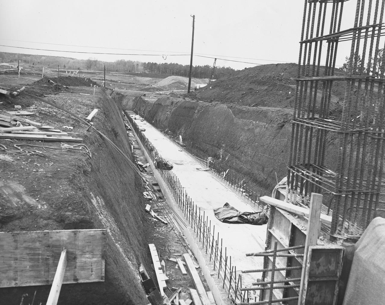
At its founding, the Marshall Space Flight Center (MSFC) inherited the Army’s Jupiter and Redstone test stands, but much larger facilities were needed for the giant stages of the Saturn V. From 1960 to 1964, the existing stands were remodeled and a sizable new test area was developed. The new comprehensive test complex for propulsion and structural dynamics was unique within the nation and the free world, and they remain so today because they were constructed with foresight to meet the future as well as on going needs. Construction of the S-IC Static test stand complex began in 1961 in the west test area of MSFC, and was completed in 1964. The S-IC static test stand was designed to develop and test the 138-ft long and 33-ft diameter Saturn V S-IC first stage, or booster stage, weighing in at 280,000 pounds. Required to hold down the brute force of a 7,500,000-pound thrust produced by 5 F-1 engines, the S-IC static test stand was designed and constructed with the strength of hundreds of tons of steel and 12,000,000 pounds of cement, planted down to bedrock 40 feet below ground level. The foundation walls, constructed with concrete and steel, are 4 feet thick. The base structure consists of four towers with 40-foot-thick walls extending upward 144 feet above ground level. The structure was topped by a crane with a 135-foot boom. With the boom in the upright position, the stand was given an overall height of 405 feet, placing it among the highest structures in Alabama at the time. In addition to the stand itself, related facilities were constructed during this time. Built directly east of the test stand was the Block House, which served as the control center for the test stand. The two were connected by a narrow access tunnel which housed the cables for the controls. Again to the east, just south of the Block House, was a newly constructed Pump House. Its function was to provide water to the stand to prevent melting damage during testing. The water was sprayed through small holes in the S-IC test stand’s 1900 ton water deflector at the rate of 320,000 gallons per minute. This photo, taken March 15, 1962, shows the excavation of the water line area connecting the Pump House to the S-IC test stand.
At its founding, the Marshall Space Flight Center (MSFC) inherited the Army’s Jupiter and Redstone test stands, but much larger facilities were needed for the giant stages of the Saturn V. From 1960 to 1964, the existing stands were remodeled and a sizable new test area was developed. The new comprehensive test complex for propulsion and structural dynamics was unique within the nation and the free world, and they remain so today because they were constructed with foresight to meet the future as well as on going needs. Construction of the S-IC Static test stand complex began in 1961 in the west test area of MSFC, and was completed in 1964. The S-IC static test stand was designed to develop and test the 138-ft long and 33-ft diameter Saturn V S-IC first stage, or booster stage, weighing in at 280,000 pounds. Required to hold down the brute force of a 7,500,000-pound thrust produced by 5 F-1 engines, the S-IC static test stand was designed and constructed with the strength of hundreds of tons of steel and 12,000,000 pounds of cement, planted down to bedrock 40 feet below ground level. The foundation walls, constructed with concrete and steel, are 4 feet thick. The base structure consists of four towers with 40-foot-thick walls extending upward 144 feet above ground level. The structure was topped by a crane with a 135-foot boom. With the boom in the upright position, the stand was given an overall height of 405 feet, placing it among the highest structures in Alabama at the time. In addition to the stand itself, related facilities were constructed during this time. Built directly east of the test stand was the Block House, which served as the control center for the test stand. The two were connected by a narrow access tunnel which housed the cables for the controls. Again to the east, just south of the Block House, was a newly constructed Pump House. Its function was to provide water to the stand to prevent melting damage during testing. The water was sprayed through small holes in the stand’s 1900 ton water deflector at the rate of 320,000 gallons per minute. This photo, taken April 4, 1963, depicts the portion of the massive water line that was installed into the S-IC test Stand.
At Launch Complex 34, the Six-Phase Soil Heating site that is involved in a groundwater cleanup project can be seen. The project involves the Department of Defense, Environmental Protection Agency, Department of Energy and NASA. Concentrations of trichloroethylene solvent have been identified in the soil at the complex as a result of cleaning methods for rocket parts during the Apollo Program, which used the complex, in the 60s. The group formed the Interagency NDAPL Consortium (IDC) to study three contamination cleanup technologies: Six-Phase Soil Heating, Steam Injection and In Situ Oxidation with Potassium Permanganate. All three methods may offer a way to remove the contaminants in months instead of decades. In the background is the block house for the complex. KSC hosted a two-day conference that presented information and demonstrations of the three technologies being tested at the site
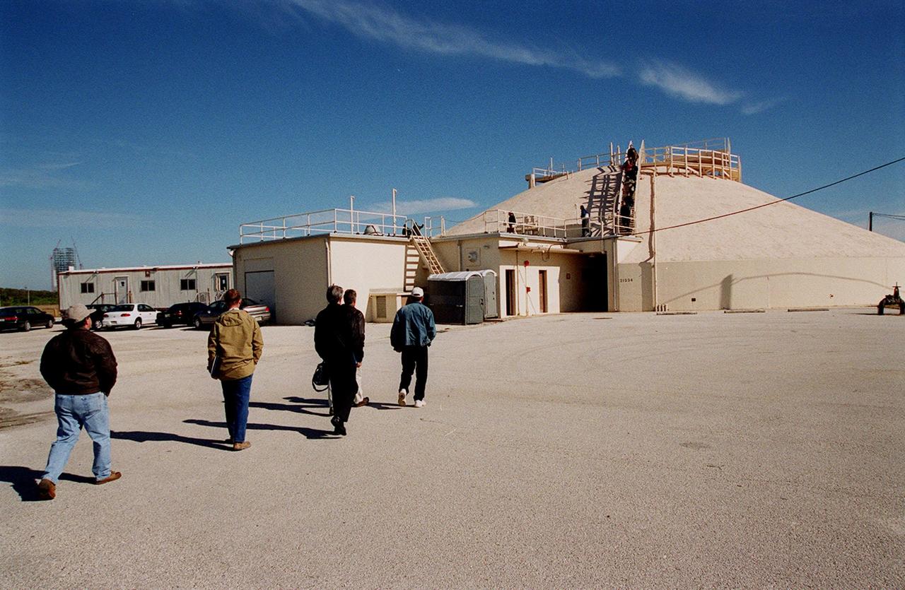
At Launch Complex 34, representatives from environmental and Federal agencies head for the block house during presentations about the environmental research project that involves the Department of Defense, Environmental Protection Agency, Department of Energy and NASA in a groundwater cleanup effort. Concentrations of trichloroethylene solvent have been identified in the soil at the complex as a result of cleaning methods for rocket parts during the Apollo Program, which used the complex, in the 60s. The group formed the Interagency NDAPL Consortium (IDC) to study three contamination cleanup technologies: Six Phase Soil Heating, Steam Injection and In Situ Oxidation with Potassium Permanganate. All three methods may offer a way to remove the contaminants in months instead of decades. KSC hosted a two-day conference that presented information and demonstrations of the three technologies being tested at the site

At Launch Complex 34, representatives from environmental and Federal agencies head for the block house during presentations about the environmental research project that involves the Department of Defense, Environmental Protection Agency, Department of Energy and NASA in a groundwater cleanup effort. Concentrations of trichloroethylene solvent have been identified in the soil at the complex as a result of cleaning methods for rocket parts during the Apollo Program, which used the complex, in the 60s. The group formed the Interagency NDAPL Consortium (IDC) to study three contamination cleanup technologies: Six Phase Soil Heating, Steam Injection and In Situ Oxidation with Potassium Permanganate. All three methods may offer a way to remove the contaminants in months instead of decades. KSC hosted a two-day conference that presented information and demonstrations of the three technologies being tested at the site

At Launch Complex 34, the Six-Phase Soil Heating site that is involved in a groundwater cleanup project can be seen. The project involves the Department of Defense, Environmental Protection Agency, Department of Energy and NASA. Concentrations of trichloroethylene solvent have been identified in the soil at the complex as a result of cleaning methods for rocket parts during the Apollo Program, which used the complex, in the 60s. The group formed the Interagency NDAPL Consortium (IDC) to study three contamination cleanup technologies: Six-Phase Soil Heating, Steam Injection and In Situ Oxidation with Potassium Permanganate. All three methods may offer a way to remove the contaminants in months instead of decades. In the background is the block house for the complex. KSC hosted a two-day conference that presented information and demonstrations of the three technologies being tested at the site
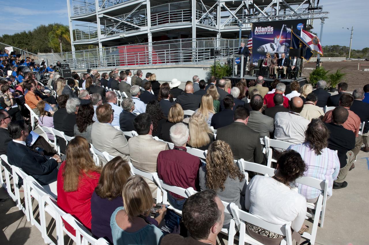
CAPE CANAVERAL, Fla. – In the Shuttle Plaza area at the Kennedy Space Center Visitor Complex (KSCVC) in Florida, Chief Operating Officer Bill Moore speaks during the Ground Breaking Ceremony for the future home of space shuttle Atlantis. Seated at right, are Kennedy Space Center Deputy Director Janet Petro; Lt. Governor of Florida Jennifer Carroll; and Jeremy Jacobs, chairman and chief executive officer of Delaware North Companies. Partially blocked from view is STS-135 Commander Chris Ferguson. Delaware North Parks & Resorts, in partnership with NASA’s Kennedy Space Center, broke ground for the 65,000 square-foot exhibit that will house Atlantis at the visitor complex. For more information, visit www.KennedySpaceCenter.com. Photo credit: NASA/Kim Shiflett
At its founding, the Marshall Space Flight Center (MSFC) inherited the Army’s Jupiter and Redstone test stands, but much larger facilities were needed for the giant stages of the Saturn V. From 1960 to 1964, the existing stands were remodeled and a sizable new test area was developed. The new comprehensive test complex for propulsion and structural dynamics was unique within the nation and the free world, and they remain so today because they were constructed with foresight to meet the future as well as on going needs. Construction of the S-IC Static test stand complex began in 1961 in the west test area of MSFC, and was completed in 1964. The S-IC static test stand was designed to develop and test the 138-ft long and 33-ft diameter Saturn V S-IC first stage, or booster stage, weighing in at 280,000 pounds. Required to hold down the brute force of a 7,500,000-pound thrust produced by 5 F-1 engines, the S-IC static test stand was designed and constructed with the strength of hundreds of tons of steel and 12,000,000 pounds of cement, planted down to bedrock 40 feet below ground level. The foundation walls, constructed with concrete and steel, are 4 feet thick. The base structure consists of four towers with 40-foot-thick walls extending upward 144 feet above ground level. The structure was topped by a crane with a 135-foot boom. With the boom in the upright position, the stand was given an overall height of 405 feet, placing it among the highest structures in Alabama at the time. In addition to the S-IC stand, additional related facilities were built during this time frame. Built to the east of the S-IC stand, the block house served as the control room. To the south of the blockhouse was a newly constructed pump house used for delivering water to the S-IC stand during testing. North of the massive test stand, the F-1 Engine test stand was built for testing a single F-1 engine. Just southeast of the S-IC stand a concrete bunker house was constructed. The bunker housed an emergency crew clad in fire proof gear, who were close at hand should any emergencies arise during testing. This photo of the completed bunker house was taken on May 7, 1963.
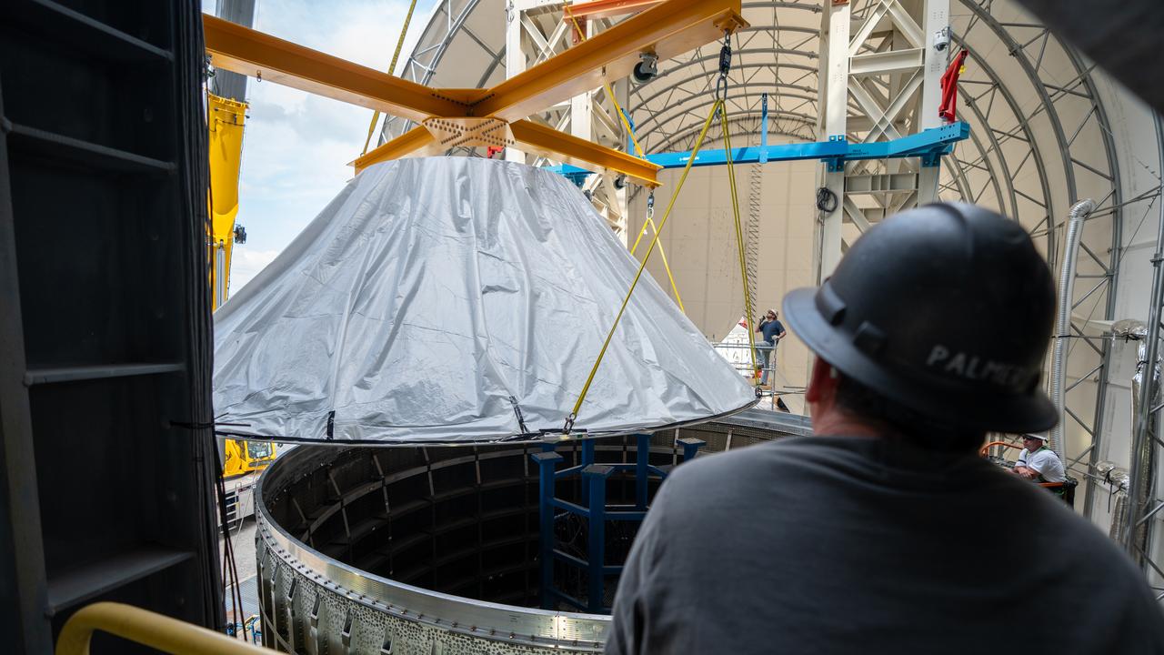
These photos and videos show how crews at NASA’s Marshall Space Flight Center in Huntsville, Alabama, moved and installed the payload adapter that will be used in the Block 1B configuration of the SLS (Space Launch System) rocket from Building 4708, where it was manufactured, into Structural Test Stand 4697 at NASA’s Marshall Space Flight Center on March 13. Teams at Marshall will begin structural testing the engineering development unit of the payload adapter – an exact replica of the flight version of the hardware – this spring. The cone-shaped payload adapter is about 8.5 feet tall and features two metal rings and eight composite panels. The adapter, which will debut on NASA’s Artemis IV mission, is an evolution from the Orion stage adapter used in the Block 1 configuration of the first three Artemis missions. It will be housed inside the universal stage adapter atop the rocket’s more powerful in-space stage, called the exploration upper stage. The payload adapter, like the launch vehicle stage adapter and the Orion stage adapter, is fully manufactured and tested at Marshall, which manages the SLS Program. NASA is working to land the first woman, first person of color, and its first international partner astronaut on the Moon under Artemis. SLS is part of NASA’s backbone for deep space exploration, along with the Orion spacecraft and Gateway in orbit around the Moon and commercial human landing systems, next-generational spacesuits, and rovers on the lunar surface. SLS is the only rocket that can send Orion, astronauts, and supplies to the Moon in a single launch.
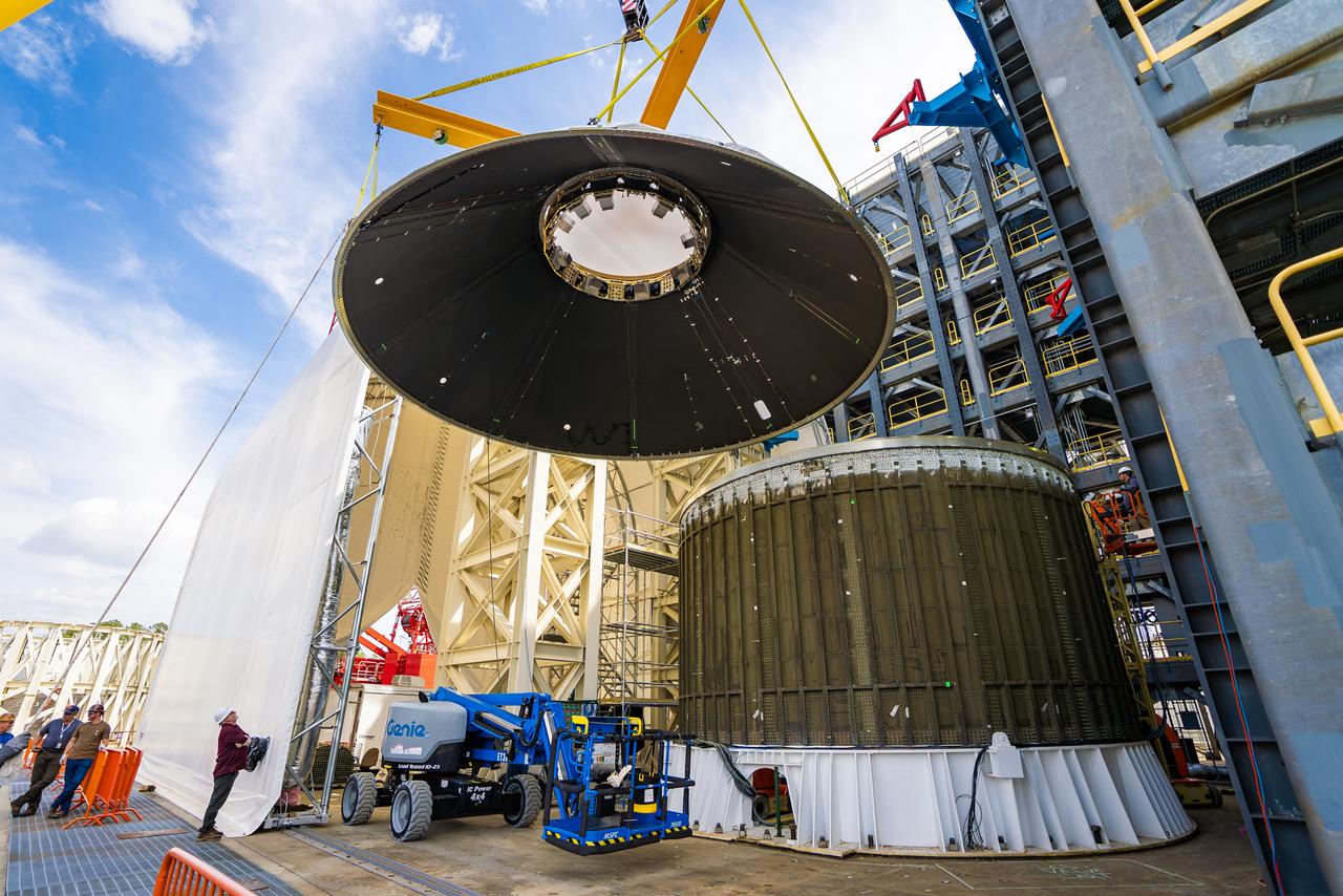
These photos and videos show how crews at NASA’s Marshall Space Flight Center in Huntsville, Alabama, moved and installed the payload adapter that will be used in the Block 1B configuration of the SLS (Space Launch System) rocket from Building 4708, where it was manufactured, into Structural Test Stand 4697 at NASA’s Marshall Space Flight Center on March 13. Teams at Marshall will begin structural testing the engineering development unit of the payload adapter – an exact replica of the flight version of the hardware – this spring. The cone-shaped payload adapter is about 8.5 feet tall and features two metal rings and eight composite panels. The adapter, which will debut on NASA’s Artemis IV mission, is an evolution from the Orion stage adapter used in the Block 1 configuration of the first three Artemis missions. It will be housed inside the universal stage adapter atop the rocket’s more powerful in-space stage, called the exploration upper stage. The payload adapter, like the launch vehicle stage adapter and the Orion stage adapter, is fully manufactured and tested at Marshall, which manages the SLS Program. NASA is working to land the first woman, first person of color, and its first international partner astronaut on the Moon under Artemis. SLS is part of NASA’s backbone for deep space exploration, along with the Orion spacecraft and Gateway in orbit around the Moon and commercial human landing systems, next-generational spacesuits, and rovers on the lunar surface. SLS is the only rocket that can send Orion, astronauts, and supplies to the Moon in a single launch.
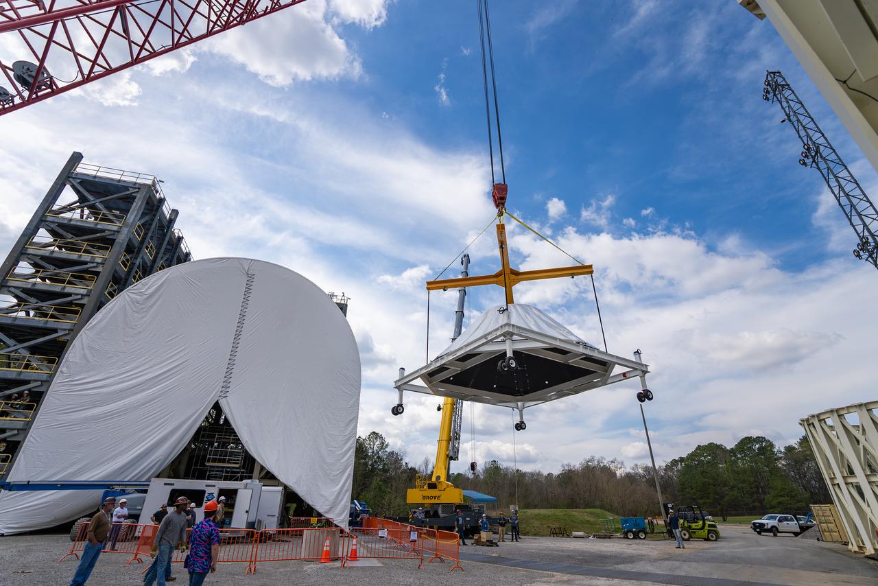
These photos and videos show how crews at NASA’s Marshall Space Flight Center in Huntsville, Alabama, moved and installed the payload adapter that will be used in the Block 1B configuration of the SLS (Space Launch System) rocket from Building 4708, where it was manufactured, into Structural Test Stand 4697 at NASA’s Marshall Space Flight Center on March 13. Teams at Marshall will begin structural testing the engineering development unit of the payload adapter – an exact replica of the flight version of the hardware – this spring. The cone-shaped payload adapter is about 8.5 feet tall and features two metal rings and eight composite panels. The adapter, which will debut on NASA’s Artemis IV mission, is an evolution from the Orion stage adapter used in the Block 1 configuration of the first three Artemis missions. It will be housed inside the universal stage adapter atop the rocket’s more powerful in-space stage, called the exploration upper stage. The payload adapter, like the launch vehicle stage adapter and the Orion stage adapter, is fully manufactured and tested at Marshall, which manages the SLS Program. NASA is working to land the first woman, first person of color, and its first international partner astronaut on the Moon under Artemis. SLS is part of NASA’s backbone for deep space exploration, along with the Orion spacecraft and Gateway in orbit around the Moon and commercial human landing systems, next-generational spacesuits, and rovers on the lunar surface. SLS is the only rocket that can send Orion, astronauts, and supplies to the Moon in a single launch.
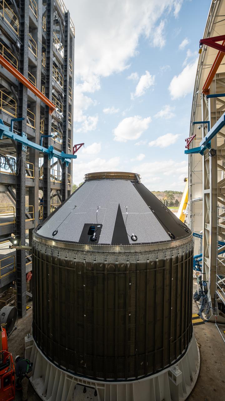
These photos and videos show how crews at NASA’s Marshall Space Flight Center in Huntsville, Alabama, moved and installed the payload adapter that will be used in the Block 1B configuration of the SLS (Space Launch System) rocket from Building 4708, where it was manufactured, into Structural Test Stand 4697 at NASA’s Marshall Space Flight Center on March 13. Teams at Marshall will begin structural testing the engineering development unit of the payload adapter – an exact replica of the flight version of the hardware – this spring. The cone-shaped payload adapter is about 8.5 feet tall and features two metal rings and eight composite panels. The adapter, which will debut on NASA’s Artemis IV mission, is an evolution from the Orion stage adapter used in the Block 1 configuration of the first three Artemis missions. It will be housed inside the universal stage adapter atop the rocket’s more powerful in-space stage, called the exploration upper stage. The payload adapter, like the launch vehicle stage adapter and the Orion stage adapter, is fully manufactured and tested at Marshall, which manages the SLS Program. NASA is working to land the first woman, first person of color, and its first international partner astronaut on the Moon under Artemis. SLS is part of NASA’s backbone for deep space exploration, along with the Orion spacecraft and Gateway in orbit around the Moon and commercial human landing systems, next-generational spacesuits, and rovers on the lunar surface. SLS is the only rocket that can send Orion, astronauts, and supplies to the Moon in a single launch.
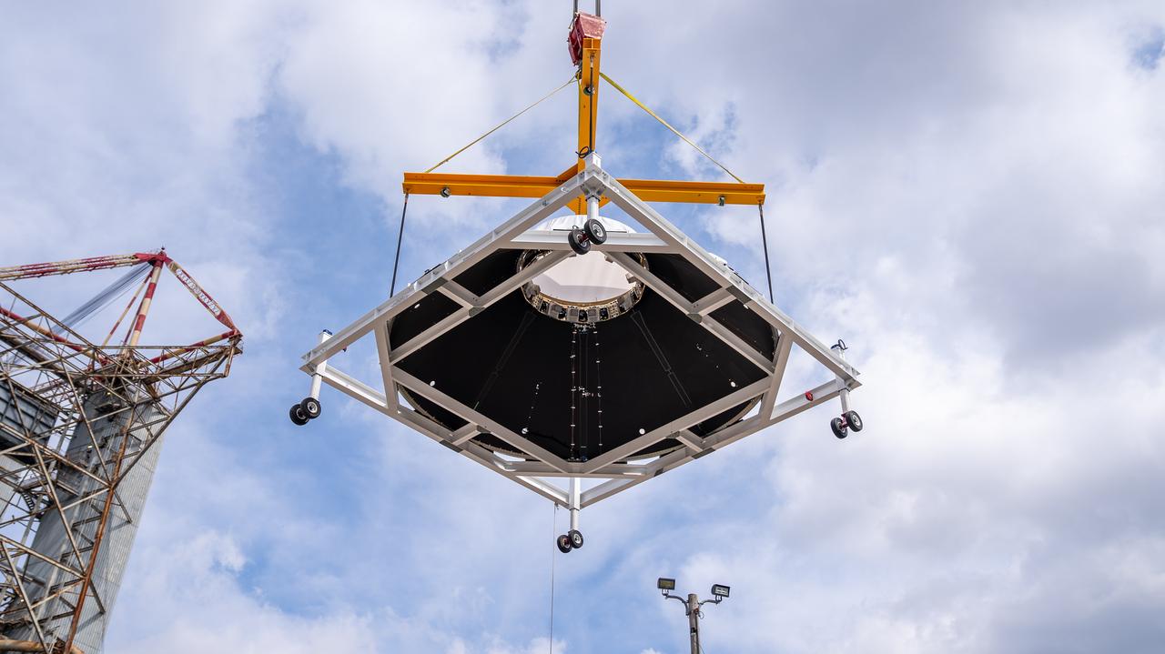
These photos and videos show how crews at NASA’s Marshall Space Flight Center in Huntsville, Alabama, moved and installed the payload adapter that will be used in the Block 1B configuration of the SLS (Space Launch System) rocket from Building 4708, where it was manufactured, into Structural Test Stand 4697 at NASA’s Marshall Space Flight Center on March 13. Teams at Marshall will begin structural testing the engineering development unit of the payload adapter – an exact replica of the flight version of the hardware – this spring. The cone-shaped payload adapter is about 8.5 feet tall and features two metal rings and eight composite panels. The adapter, which will debut on NASA’s Artemis IV mission, is an evolution from the Orion stage adapter used in the Block 1 configuration of the first three Artemis missions. It will be housed inside the universal stage adapter atop the rocket’s more powerful in-space stage, called the exploration upper stage. The payload adapter, like the launch vehicle stage adapter and the Orion stage adapter, is fully manufactured and tested at Marshall, which manages the SLS Program. NASA is working to land the first woman, first person of color, and its first international partner astronaut on the Moon under Artemis. SLS is part of NASA’s backbone for deep space exploration, along with the Orion spacecraft and Gateway in orbit around the Moon and commercial human landing systems, next-generational spacesuits, and rovers on the lunar surface. SLS is the only rocket that can send Orion, astronauts, and supplies to the Moon in a single launch.
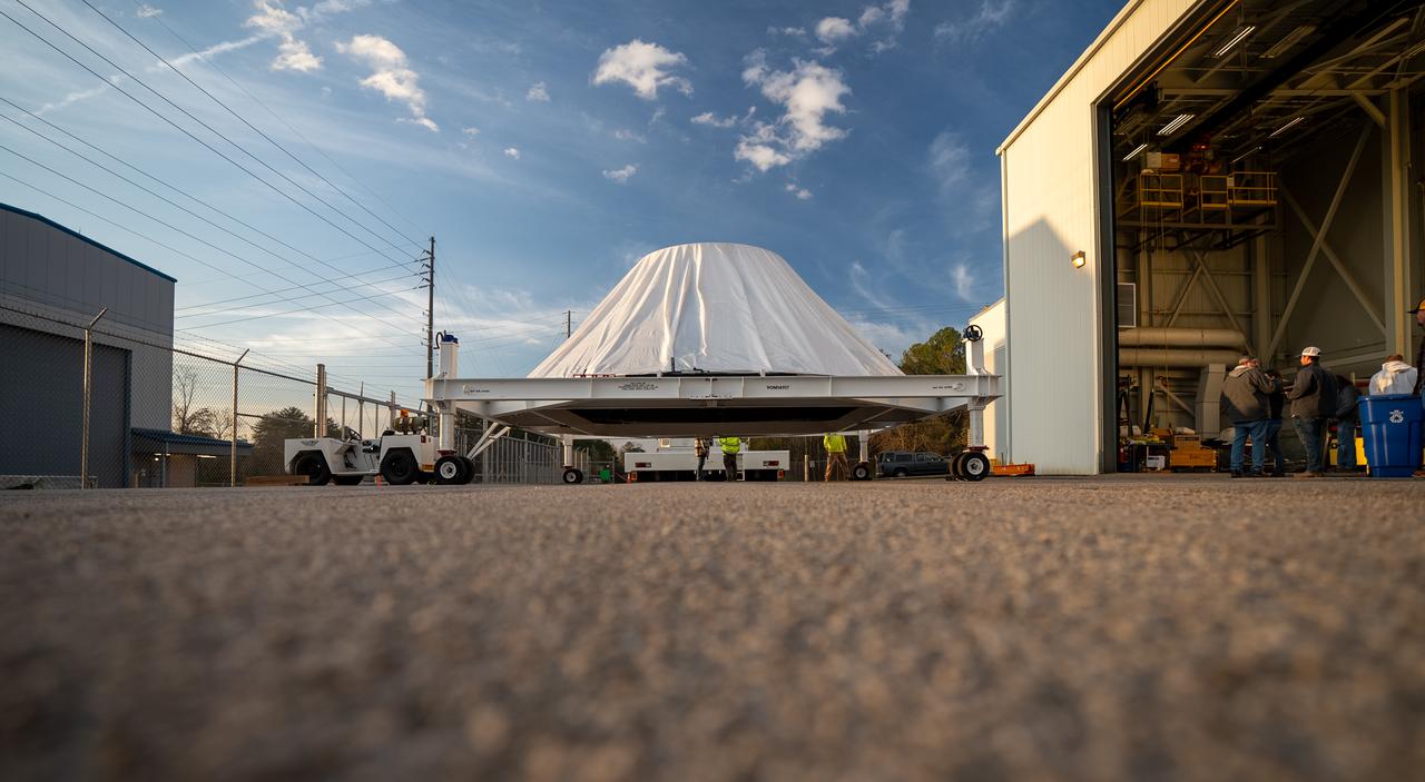
These photos and videos show how crews at NASA’s Marshall Space Flight Center in Huntsville, Alabama, moved and installed the payload adapter that will be used in the Block 1B configuration of the SLS (Space Launch System) rocket from Building 4708, where it was manufactured, into Structural Test Stand 4697 at NASA’s Marshall Space Flight Center on March 13. Teams at Marshall will begin structural testing the engineering development unit of the payload adapter – an exact replica of the flight version of the hardware – this spring. The cone-shaped payload adapter is about 8.5 feet tall and features two metal rings and eight composite panels. The adapter, which will debut on NASA’s Artemis IV mission, is an evolution from the Orion stage adapter used in the Block 1 configuration of the first three Artemis missions. It will be housed inside the universal stage adapter atop the rocket’s more powerful in-space stage, called the exploration upper stage. The payload adapter, like the launch vehicle stage adapter and the Orion stage adapter, is fully manufactured and tested at Marshall, which manages the SLS Program. NASA is working to land the first woman, first person of color, and its first international partner astronaut on the Moon under Artemis. SLS is part of NASA’s backbone for deep space exploration, along with the Orion spacecraft and Gateway in orbit around the Moon and commercial human landing systems, next-generational spacesuits, and rovers on the lunar surface. SLS is the only rocket that can send Orion, astronauts, and supplies to the Moon in a single launch.
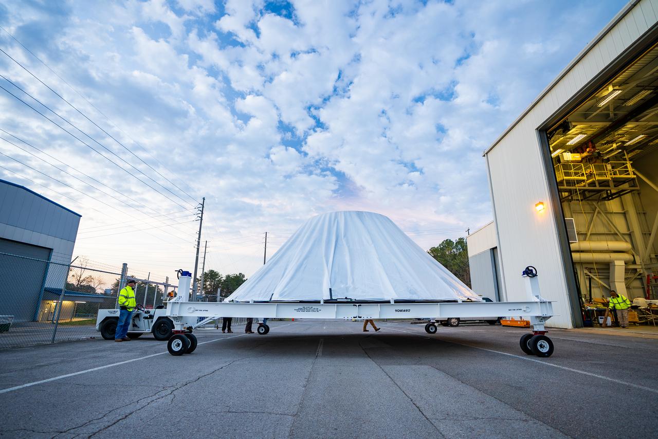
These photos and videos show how crews at NASA’s Marshall Space Flight Center in Huntsville, Alabama, moved and installed the payload adapter that will be used in the Block 1B configuration of the SLS (Space Launch System) rocket from Building 4708, where it was manufactured, into Structural Test Stand 4697 at NASA’s Marshall Space Flight Center on March 13. Teams at Marshall will begin structural testing the engineering development unit of the payload adapter – an exact replica of the flight version of the hardware – this spring. The cone-shaped payload adapter is about 8.5 feet tall and features two metal rings and eight composite panels. The adapter, which will debut on NASA’s Artemis IV mission, is an evolution from the Orion stage adapter used in the Block 1 configuration of the first three Artemis missions. It will be housed inside the universal stage adapter atop the rocket’s more powerful in-space stage, called the exploration upper stage. The payload adapter, like the launch vehicle stage adapter and the Orion stage adapter, is fully manufactured and tested at Marshall, which manages the SLS Program. NASA is working to land the first woman, first person of color, and its first international partner astronaut on the Moon under Artemis. SLS is part of NASA’s backbone for deep space exploration, along with the Orion spacecraft and Gateway in orbit around the Moon and commercial human landing systems, next-generational spacesuits, and rovers on the lunar surface. SLS is the only rocket that can send Orion, astronauts, and supplies to the Moon in a single launch.
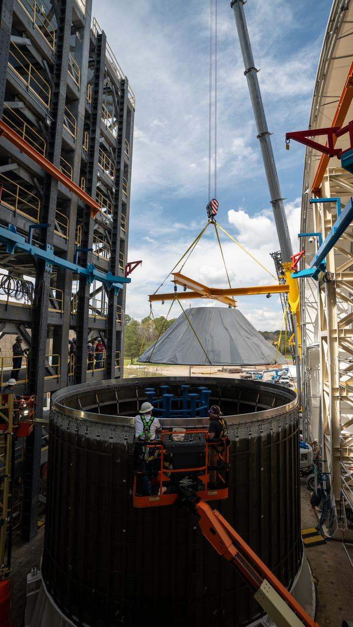
These photos and videos show how crews at NASA’s Marshall Space Flight Center in Huntsville, Alabama, moved and installed the payload adapter that will be used in the Block 1B configuration of the SLS (Space Launch System) rocket from Building 4708, where it was manufactured, into Structural Test Stand 4697 at NASA’s Marshall Space Flight Center on March 13. Teams at Marshall will begin structural testing the engineering development unit of the payload adapter – an exact replica of the flight version of the hardware – this spring. The cone-shaped payload adapter is about 8.5 feet tall and features two metal rings and eight composite panels. The adapter, which will debut on NASA’s Artemis IV mission, is an evolution from the Orion stage adapter used in the Block 1 configuration of the first three Artemis missions. It will be housed inside the universal stage adapter atop the rocket’s more powerful in-space stage, called the exploration upper stage. The payload adapter, like the launch vehicle stage adapter and the Orion stage adapter, is fully manufactured and tested at Marshall, which manages the SLS Program. NASA is working to land the first woman, first person of color, and its first international partner astronaut on the Moon under Artemis. SLS is part of NASA’s backbone for deep space exploration, along with the Orion spacecraft and Gateway in orbit around the Moon and commercial human landing systems, next-generational spacesuits, and rovers on the lunar surface. SLS is the only rocket that can send Orion, astronauts, and supplies to the Moon in a single launch.
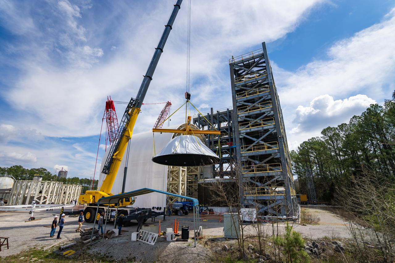
These photos and videos show how crews at NASA’s Marshall Space Flight Center in Huntsville, Alabama, moved and installed the payload adapter that will be used in the Block 1B configuration of the SLS (Space Launch System) rocket from Building 4708, where it was manufactured, into Structural Test Stand 4697 at NASA’s Marshall Space Flight Center on March 13. Teams at Marshall will begin structural testing the engineering development unit of the payload adapter – an exact replica of the flight version of the hardware – this spring. The cone-shaped payload adapter is about 8.5 feet tall and features two metal rings and eight composite panels. The adapter, which will debut on NASA’s Artemis IV mission, is an evolution from the Orion stage adapter used in the Block 1 configuration of the first three Artemis missions. It will be housed inside the universal stage adapter atop the rocket’s more powerful in-space stage, called the exploration upper stage. The payload adapter, like the launch vehicle stage adapter and the Orion stage adapter, is fully manufactured and tested at Marshall, which manages the SLS Program. NASA is working to land the first woman, first person of color, and its first international partner astronaut on the Moon under Artemis. SLS is part of NASA’s backbone for deep space exploration, along with the Orion spacecraft and Gateway in orbit around the Moon and commercial human landing systems, next-generational spacesuits, and rovers on the lunar surface. SLS is the only rocket that can send Orion, astronauts, and supplies to the Moon in a single launch.
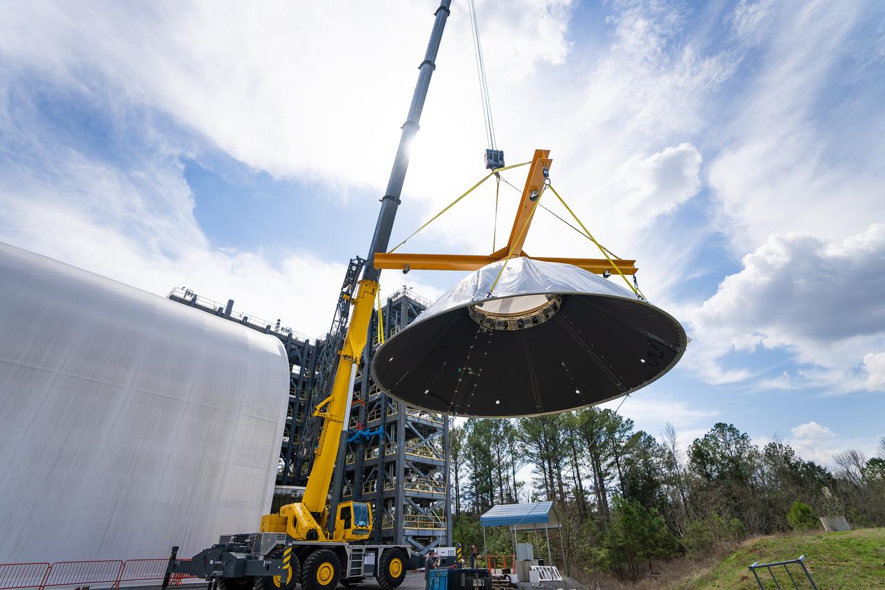
These photos and videos show how crews at NASA’s Marshall Space Flight Center in Huntsville, Alabama, moved and installed the payload adapter that will be used in the Block 1B configuration of the SLS (Space Launch System) rocket from Building 4708, where it was manufactured, into Structural Test Stand 4697 at NASA’s Marshall Space Flight Center on March 13. Teams at Marshall will begin structural testing the engineering development unit of the payload adapter – an exact replica of the flight version of the hardware – this spring. The cone-shaped payload adapter is about 8.5 feet tall and features two metal rings and eight composite panels. The adapter, which will debut on NASA’s Artemis IV mission, is an evolution from the Orion stage adapter used in the Block 1 configuration of the first three Artemis missions. It will be housed inside the universal stage adapter atop the rocket’s more powerful in-space stage, called the exploration upper stage. The payload adapter, like the launch vehicle stage adapter and the Orion stage adapter, is fully manufactured and tested at Marshall, which manages the SLS Program. NASA is working to land the first woman, first person of color, and its first international partner astronaut on the Moon under Artemis. SLS is part of NASA’s backbone for deep space exploration, along with the Orion spacecraft and Gateway in orbit around the Moon and commercial human landing systems, next-generational spacesuits, and rovers on the lunar surface. SLS is the only rocket that can send Orion, astronauts, and supplies to the Moon in a single launch.
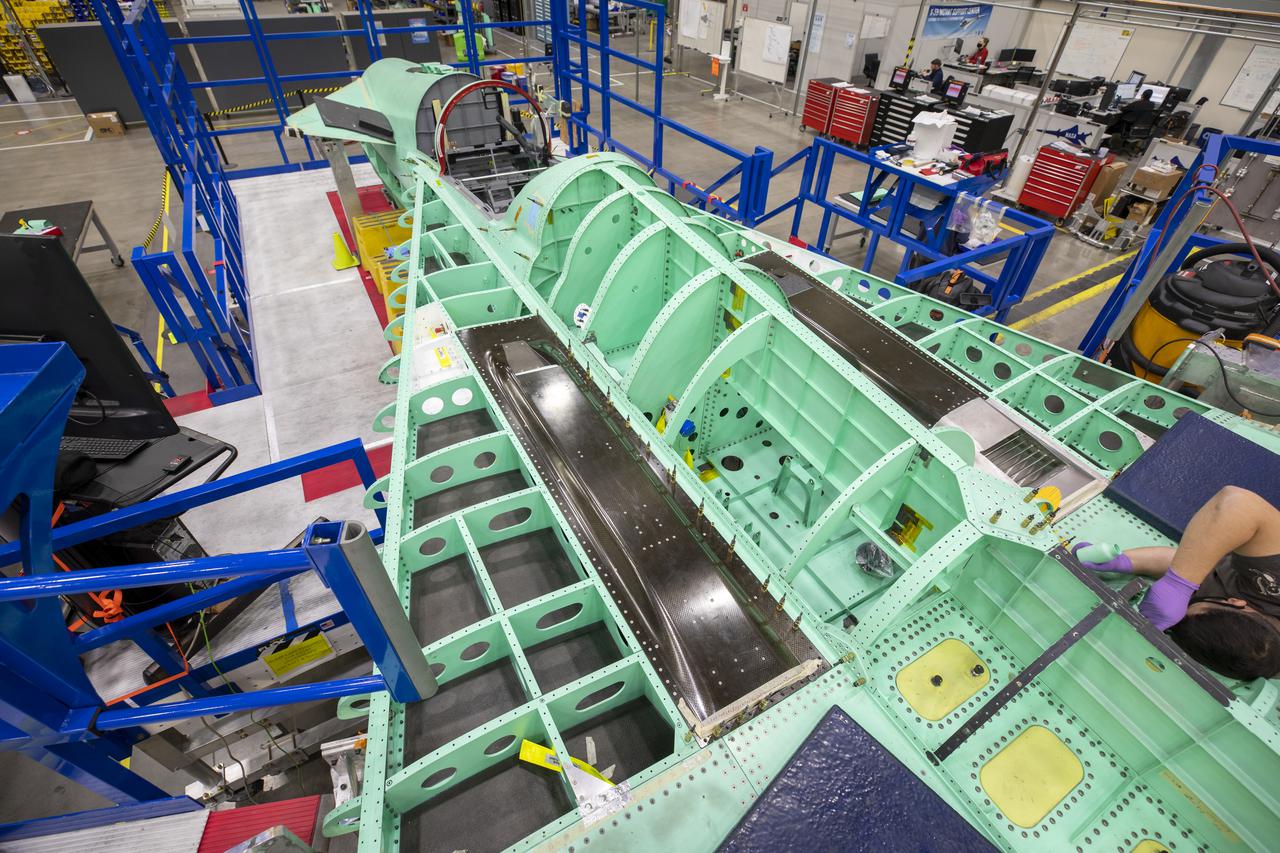
NASA is targeting 2022 for the first flight of the X-59 Quiet SuperSonic Technology (QueSST) research aircraft. Its mission – fly over communities to collect data that could cut passenger travel time in half without disturbing people on the ground. NASA’s X-59 is equipped with supersonic technologies that aid in lowering the sound of the sonic boom. In this picture, the black rectangle panels are the air intakes for the environmental control system (ECS) that regulates the temperature, cabin pressure, and air distribution. The silver grate located at the rear of one of the ECS panels is the exhaust — both of these sections are traditionally housed on the underside of the plane. By placing these features on top of the X-59 wing, the wing blocks and prevents the ECS exhaust from interacting with the shock waves on the bottom of the aircraft. This unique design approach to re-shaping the shock wave pattern substantially reduces the sonic boom to more of a sonic “thump” when it reaches the ground. Lockheed Martin Photography By Garry Tice 1011 Lockheed Way, Palmdale, Ca. 93599 Event: SEG 210 Forebody Date: 1/19/2021 Additional Info:

This is an illustration of the Space Base concept. In-house work of the Marshall Space Flight Center, as well as a Phase B contract with the McDornel Douglas Astronautics Company, resulted in a preliminary design for a space station in 1969 and l970. The Marshall-McDonnel Douglas approach envisioned the use of two common modules as the core configuration of a 12-man space station. Each common module was 33 feet in diameter and 40 feet in length and provided the building blocks, not only for the space station, but also for a 50-man space base. Coupled together, the two modules would form a four-deck facility: two decks for laboratories and two decks for operations and living quarters. Zero-gravity would be the normal mode of operation, although the station would have an artificial-gravity capability. This general-purpose orbital facility was to provide wide-ranging research capabilities. The design of the facility was driven by the need to accommodate a broad spectrum of activities in support of astronomy, astrophysics, aerospace medicine, biology, materials processing, space physics, and space manufacturing. To serve the needs of Earth observations, the station was to be placed in a 242-nautical-mile orbit at a 55-degree inclination. An Intermediate-21 vehicle (comprised of Saturn S-IC and S-II stages) would have launched the station in 1977.

At its founding, the Marshall Space Flight Center (MSFC) inherited the Army’s Jupiter and Redstone test stands, but much larger facilities were needed for the giant stages of the Saturn V. From 1960 to 1964, the existing stands were remodeled and a sizable new test area was developed. The new comprehensive test complex for propulsion and structural dynamics was unique within the nation and the free world, and they remain so today because they were constructed with foresight to meet the future as well as on going needs. Construction of the S-IC Static test stand complex began in 1961 in the west test area of MSFC, and was completed in 1964. The S-IC static test stand was originally designed to develop and test the 138-ft long and 33-ft diameter Saturn V S-IC first stage, or booster stage. Modifications to the S-IC Test Stand began in 1975 to accommodate space shuttle external tank testing. This photo, taken from the roof of the block house on October 14, 1975, provides an overall view of the stand during the modification process.
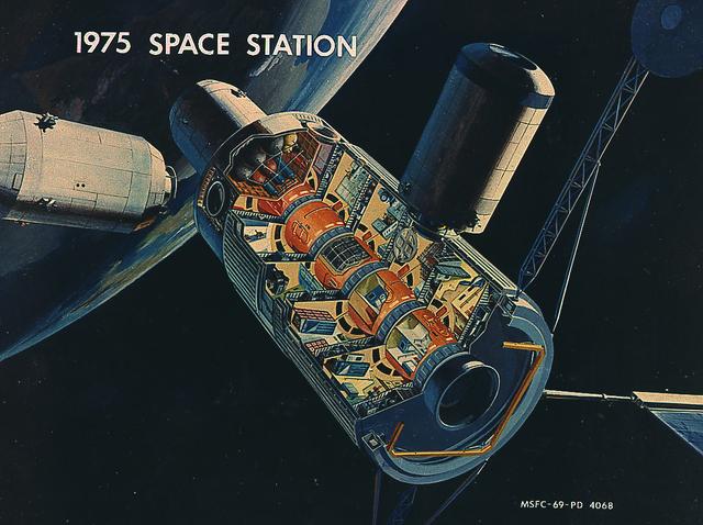
This picture illustrates a concept of a 33-Foot-Diameter Space Station Leading to a Space Base. In-house work of the Marshall Space Flight Center, as well as a Phase B contract with the McDornel Douglas Astronautics Company, resulted in a preliminary design for a space station in 1969 and l970. The Marshall-McDonnel Douglas approach envisioned the use of two common modules as the core configuration of a 12-man space station. Each common module was 33 feet in diameter and 40 feet in length and provided the building blocks, not only for the space station, but also for a 50-man space base. Coupled together, the two modules would form a four-deck facility: two decks for laboratories and two decks for operations and living quarters. Zero-gravity would be the normal mode of operation, although the station would have an artificial gravity capability. This general-purpose orbital facility was to provide wide-ranging research capabilities. The design of the facility was driven by the need to accommodate a broad spectrum of activities in support of astronomy, astrophysics, aerospace medicine, biology, materials processing, space physics, and space manufacturing. To serve the needs of Earth observations, the station was to be placed in a 242-nautical-mile orbit at a 55-degree inclination. An Intermediate-21 vehicle (comprised of Saturn S-IC and S-II stages) would have launched the station in 1977.
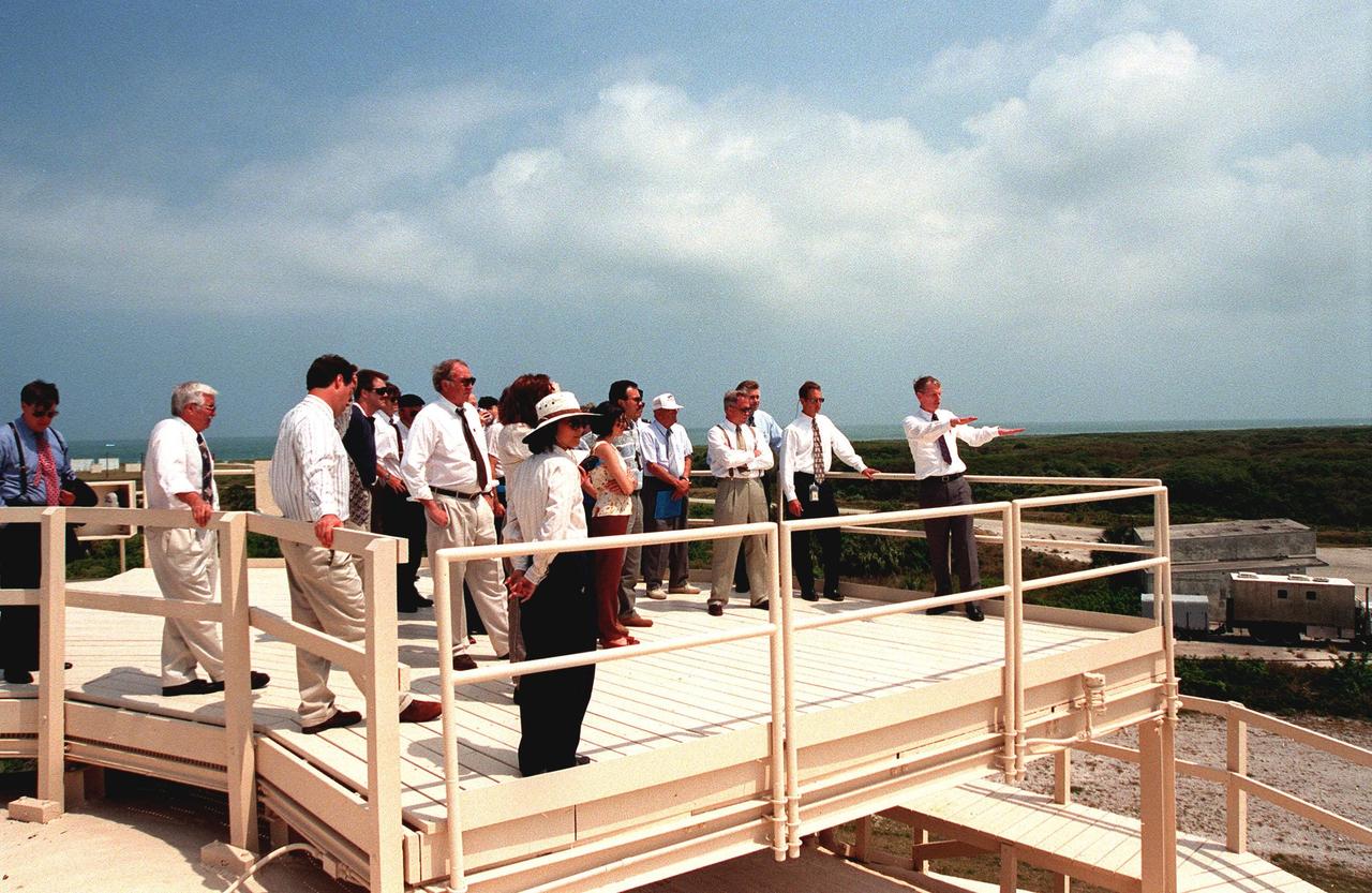
Key participants in the signing of a Memorandum of Agreement, formalizing cooperative efforts of NASA, the U.S. Air Force, and federal agencies in ground-water cleanup initiatives, gather on top of the block house at Launch Complex 34. Motioning at right is Skip Chamberlain, program manager, Office of Science and Technology, U.S. Department of Energy. Others on the tour include Timothy Oppelt, director, National Risk Management Research Laboratory, U.S. Environmental Protection Agency; Tom Heenan, assistant manager of environmental management, Savannah River Site, U.S. Department of Energy; Col. James Heald, Vice Commander, Air Force Research Laboratory, U.S. Air Force; Gerald Boyd, acting deputy assistant secretary, Office of Science and Technology, U.S. Department of Energy; James Fiore, acting deputy assistant secretary, Office of Environmental Restoration, Department of Energy; Brig. Gen. Randall R. Starbuck, Commander 45th Space Wing, U.S. Air Force; Roy Bridges Jr., director of John F. Kennedy Space Center; Walter Kovalick Jr., Ph.D., director, Technology Innovation Office, U.S. Environmental Protection Agency. NASA, the U.S. Air Force and the agencies have formed a consortium and are participating in a comparative study of three innovative techniques to be used in cleaning a contaminated area of Launch Complex 34. The study will be used to help improve groundwater cleanup processes nationally
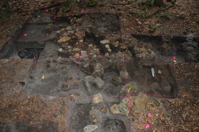
Archeological ruins of Elliot Plantation are revealed through the oak hammock on NASA’s Kennedy Space Center in Florida in 2009. Pictured is a structure composed of coquina blocks from a hearth of a large dwelling, determined to be that of the plantation overseer. The use of coquina is consistent with high-status building materials of the period. Mapped in this photo are the remnants of a chimney collapse from a detached kitchen in the overseer’s house. An enormous scatter of architectural debris, including coquina, fieldstone, brick and mortar, as well as substantial food remains, broken dishes, bottle glass, and other kitchen wares, were recovered and documented during investigations of the ruins. The ruins of Elliot Plantation date from the 1760s and represent the largest, earliest, and southernmost British period sugar plantation in the U.S., as well as one of the most intact and best examples of a completely preserved enslaved landscape. In interagency cooperation between the National Park Service, the U.S. Fish and Wildlife Service, and NASA, and with the assistance of volunteers from the Indian River Anthropological Society, and historic preservation offices of Brevard and Volusia counties, approximately 200 shovel tests and 20 excavation units were completed in three areas of the plantation complex from 2008 to 2009.
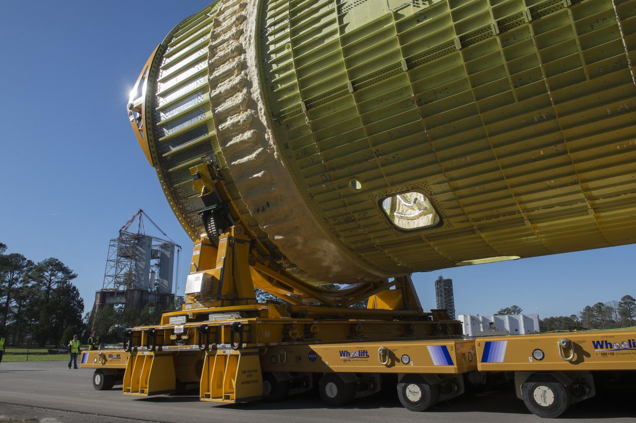
The SLS Stages Intertank Structural Test Assembly (STA) is rolling off the NASA Pegasus Barge at the MSFC Dock enroute to the MSFC 4619 Load Test Annex test facility for qualification testing via MSFC West Test Area. Historic Saturn 1-C test stand on far left, blockhouse 4670 on far right, SLS LH2 test stand, 4693, in center.
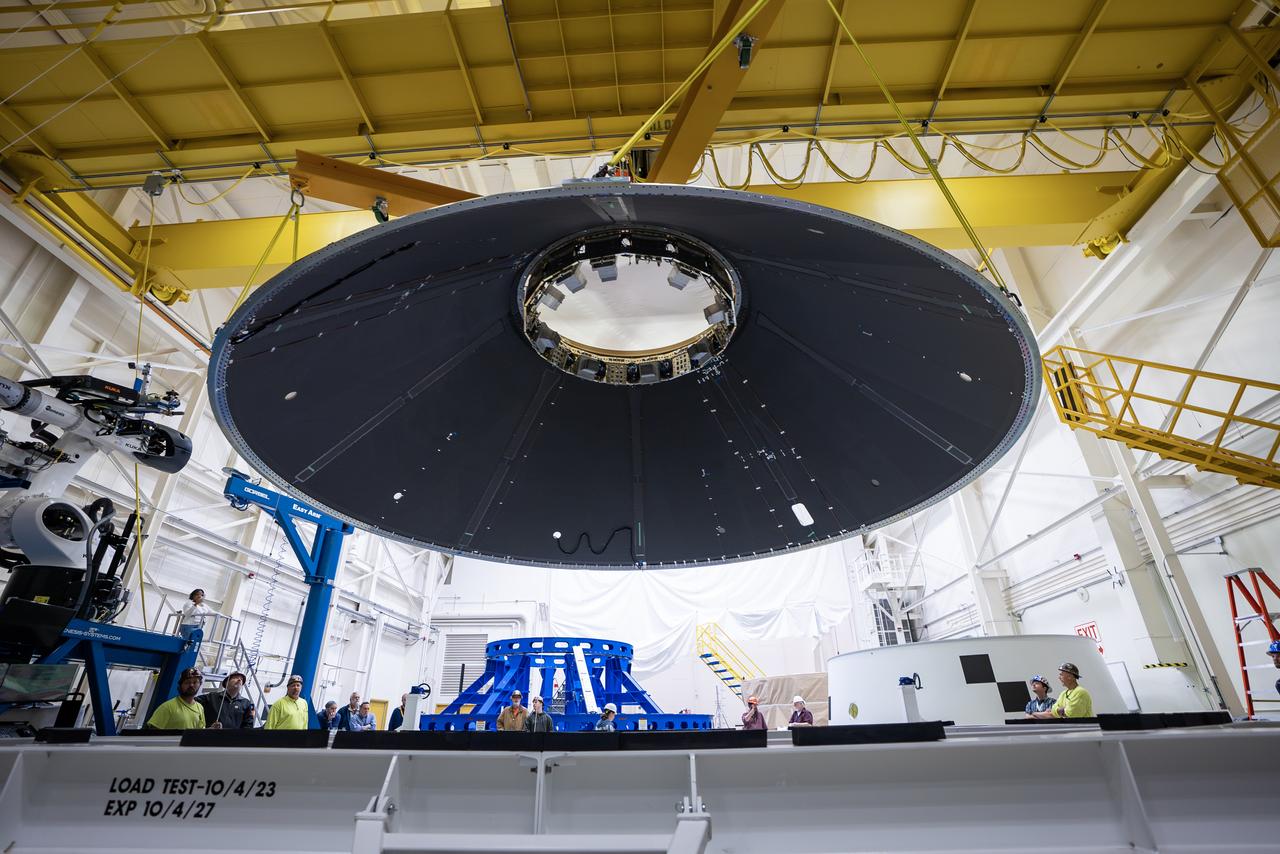
These photos and videos show how NASA manufactured and prepared to transport the payload adapter in February inside Building 4708 at NASA’s Marshall Space Flight Center in Huntsville, Alabama. Prior to moving the hardware for testing, teams installed the New Explorations Secondary Transport component, called the NEST, into the top of the engineering development unit. The NEST component will allow the hardware to hold a series of secondary payloads, or small satellites. The cone-shaped payload adapter is about 8.5 feet tall and features two metal rings and eight composite panels. The adapter, which will debut on NASA’s Artemis IV mission, is an evolution from the Orion stage adapter used in the Block 1 configuration of the rocket for the first three Artemis missions. It will be housed inside the universal stage adapter atop the rocket’s more powerful in-space stage, called the exploration upper stage. The payload adapter, like the launch vehicle stage adapter and the Orion stage adapter, is fully manufactured and tested at Marshall, which manages the SLS Program. NASA is working to land the first woman, first person of color, and its first international partner astronaut on the Moon under Artemis. SLS is part of NASA’s backbone for deep space exploration, along with the Orion spacecraft and Gateway in orbit around the Moon and commercial human landing systems, next-generational spacesuits, and rovers on the lunar surface. SLS is the only rocket that can send Orion, astronauts, and supplies to the Moon in a single launch.
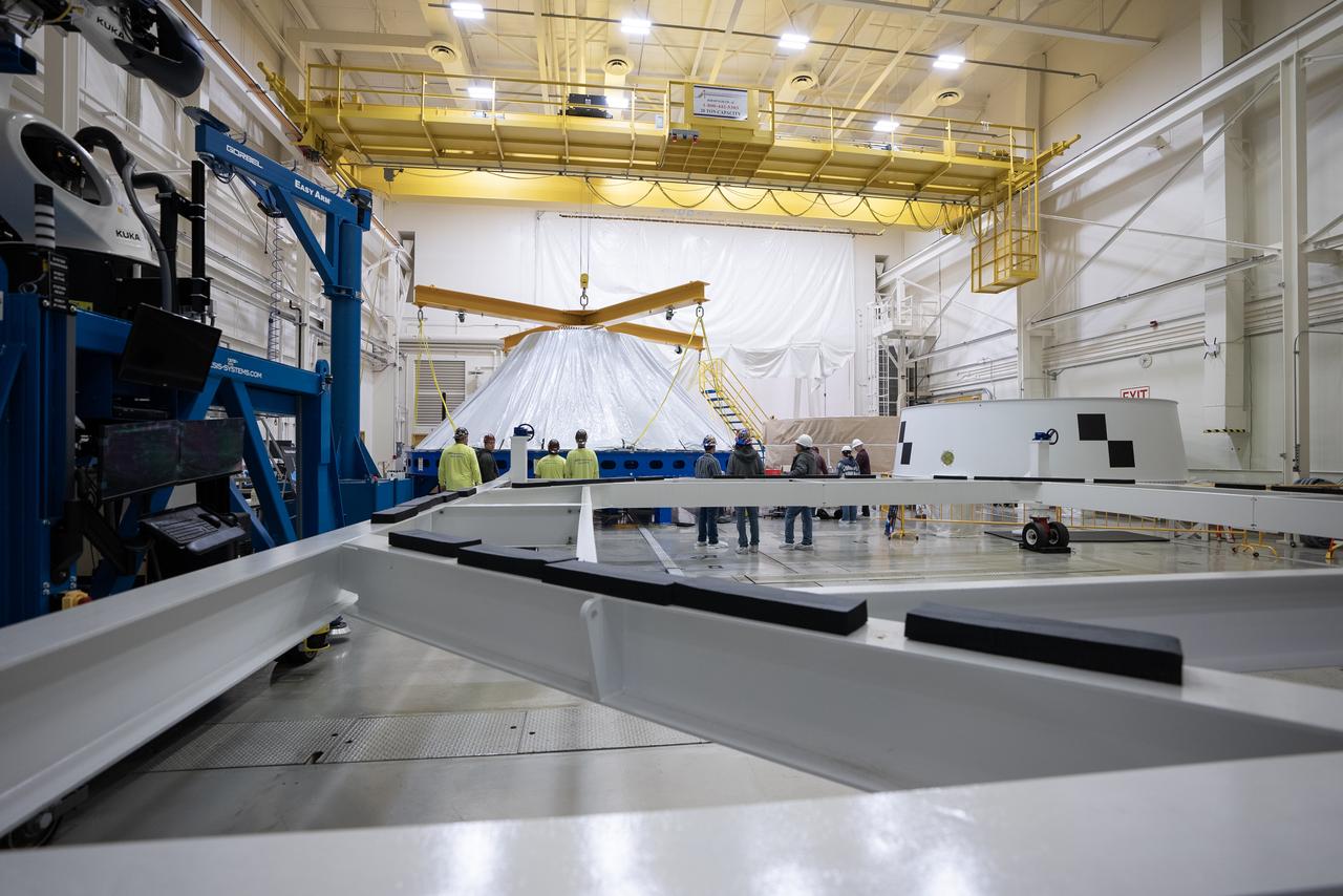
These photos and videos show how NASA manufactured and prepared to transport the payload adapter in February inside Building 4708 at NASA’s Marshall Space Flight Center in Huntsville, Alabama. Prior to moving the hardware for testing, teams installed the New Explorations Secondary Transport component, called the NEST, into the top of the engineering development unit. The NEST component will allow the hardware to hold a series of secondary payloads, or small satellites. The cone-shaped payload adapter is about 8.5 feet tall and features two metal rings and eight composite panels. The adapter, which will debut on NASA’s Artemis IV mission, is an evolution from the Orion stage adapter used in the Block 1 configuration of the rocket for the first three Artemis missions. It will be housed inside the universal stage adapter atop the rocket’s more powerful in-space stage, called the exploration upper stage. The payload adapter, like the launch vehicle stage adapter and the Orion stage adapter, is fully manufactured and tested at Marshall, which manages the SLS Program. NASA is working to land the first woman, first person of color, and its first international partner astronaut on the Moon under Artemis. SLS is part of NASA’s backbone for deep space exploration, along with the Orion spacecraft and Gateway in orbit around the Moon and commercial human landing systems, next-generational spacesuits, and rovers on the lunar surface. SLS is the only rocket that can send Orion, astronauts, and supplies to the Moon in a single launch.
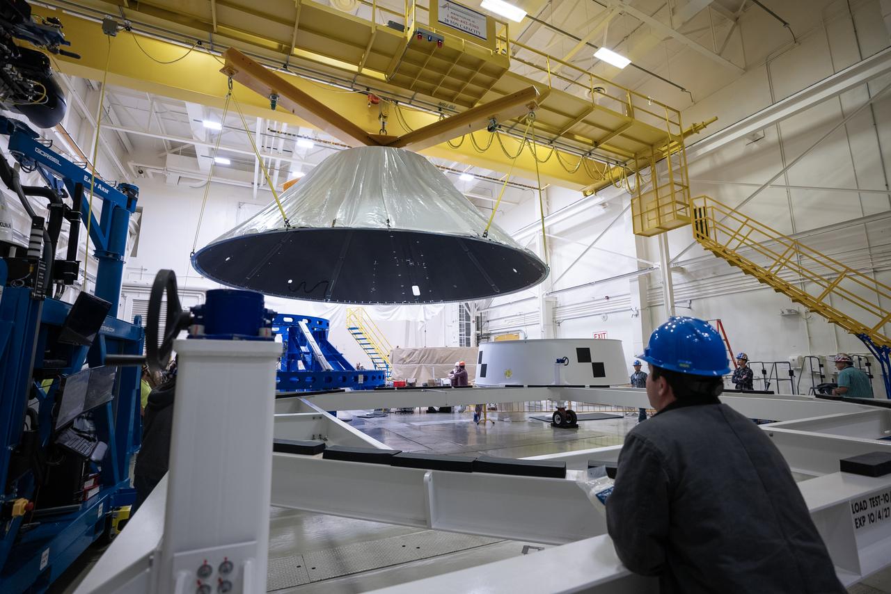
These photos and videos show how NASA manufactured and prepared to transport the payload adapter in February inside Building 4708 at NASA’s Marshall Space Flight Center in Huntsville, Alabama. Prior to moving the hardware for testing, teams installed the New Explorations Secondary Transport component, called the NEST, into the top of the engineering development unit. The NEST component will allow the hardware to hold a series of secondary payloads, or small satellites. The cone-shaped payload adapter is about 8.5 feet tall and features two metal rings and eight composite panels. The adapter, which will debut on NASA’s Artemis IV mission, is an evolution from the Orion stage adapter used in the Block 1 configuration of the rocket for the first three Artemis missions. It will be housed inside the universal stage adapter atop the rocket’s more powerful in-space stage, called the exploration upper stage. The payload adapter, like the launch vehicle stage adapter and the Orion stage adapter, is fully manufactured and tested at Marshall, which manages the SLS Program. NASA is working to land the first woman, first person of color, and its first international partner astronaut on the Moon under Artemis. SLS is part of NASA’s backbone for deep space exploration, along with the Orion spacecraft and Gateway in orbit around the Moon and commercial human landing systems, next-generational spacesuits, and rovers on the lunar surface. SLS is the only rocket that can send Orion, astronauts, and supplies to the Moon in a single launch.
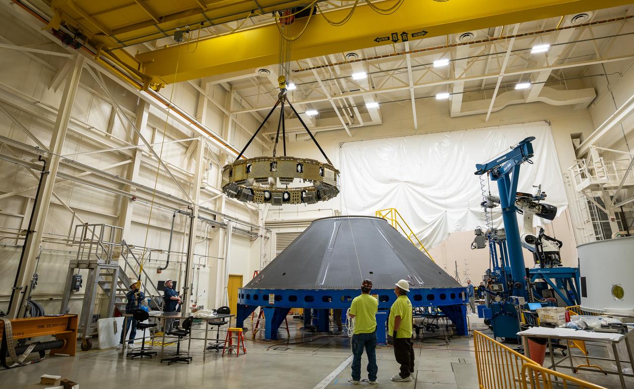
These photos and videos show how NASA manufactured and prepared to transport the payload adapter in February inside Building 4708 at NASA’s Marshall Space Flight Center in Huntsville, Alabama. Prior to moving the hardware for testing, teams installed the New Explorations Secondary Transport component, called the NEST, into the top of the engineering development unit. The NEST component will allow the hardware to hold a series of secondary payloads, or small satellites. The cone-shaped payload adapter is about 8.5 feet tall and features two metal rings and eight composite panels. The adapter, which will debut on NASA’s Artemis IV mission, is an evolution from the Orion stage adapter used in the Block 1 configuration of the rocket for the first three Artemis missions. It will be housed inside the universal stage adapter atop the rocket’s more powerful in-space stage, called the exploration upper stage. The payload adapter, like the launch vehicle stage adapter and the Orion stage adapter, is fully manufactured and tested at Marshall, which manages the SLS Program. NASA is working to land the first woman, first person of color, and its first international partner astronaut on the Moon under Artemis. SLS is part of NASA’s backbone for deep space exploration, along with the Orion spacecraft and Gateway in orbit around the Moon and commercial human landing systems, next-generational spacesuits, and rovers on the lunar surface. SLS is the only rocket that can send Orion, astronauts, and supplies to the Moon in a single launch.
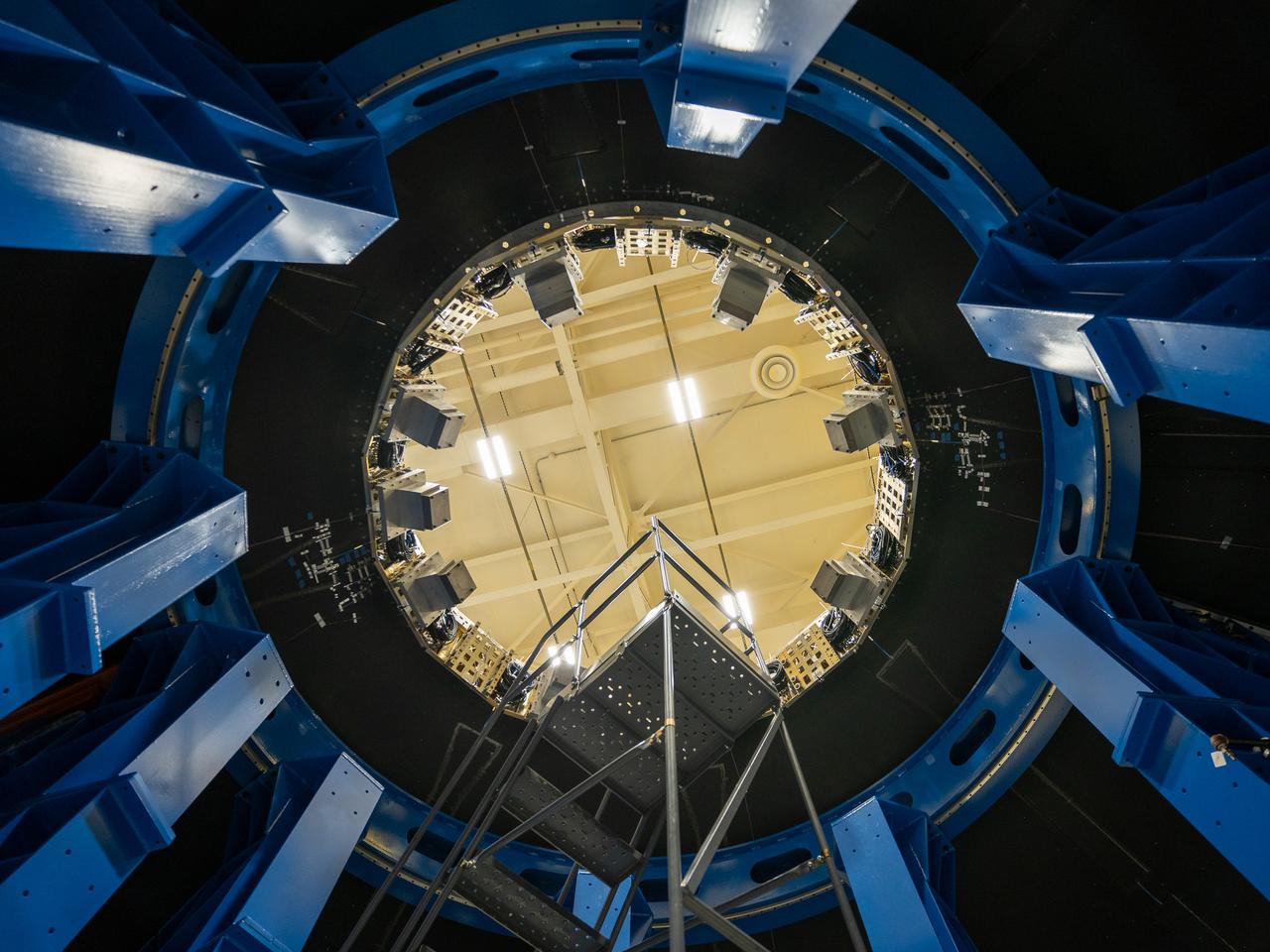
These photos and videos show how NASA manufactured and prepared to transport the payload adapter in February inside Building 4708 at NASA’s Marshall Space Flight Center in Huntsville, Alabama. Prior to moving the hardware for testing, teams installed the New Explorations Secondary Transport component, called the NEST, into the top of the engineering development unit. The NEST component will allow the hardware to hold a series of secondary payloads, or small satellites. The cone-shaped payload adapter is about 8.5 feet tall and features two metal rings and eight composite panels. The adapter, which will debut on NASA’s Artemis IV mission, is an evolution from the Orion stage adapter used in the Block 1 configuration of the rocket for the first three Artemis missions. It will be housed inside the universal stage adapter atop the rocket’s more powerful in-space stage, called the exploration upper stage. The payload adapter, like the launch vehicle stage adapter and the Orion stage adapter, is fully manufactured and tested at Marshall, which manages the SLS Program. NASA is working to land the first woman, first person of color, and its first international partner astronaut on the Moon under Artemis. SLS is part of NASA’s backbone for deep space exploration, along with the Orion spacecraft and Gateway in orbit around the Moon and commercial human landing systems, next-generational spacesuits, and rovers on the lunar surface. SLS is the only rocket that can send Orion, astronauts, and supplies to the Moon in a single launch.
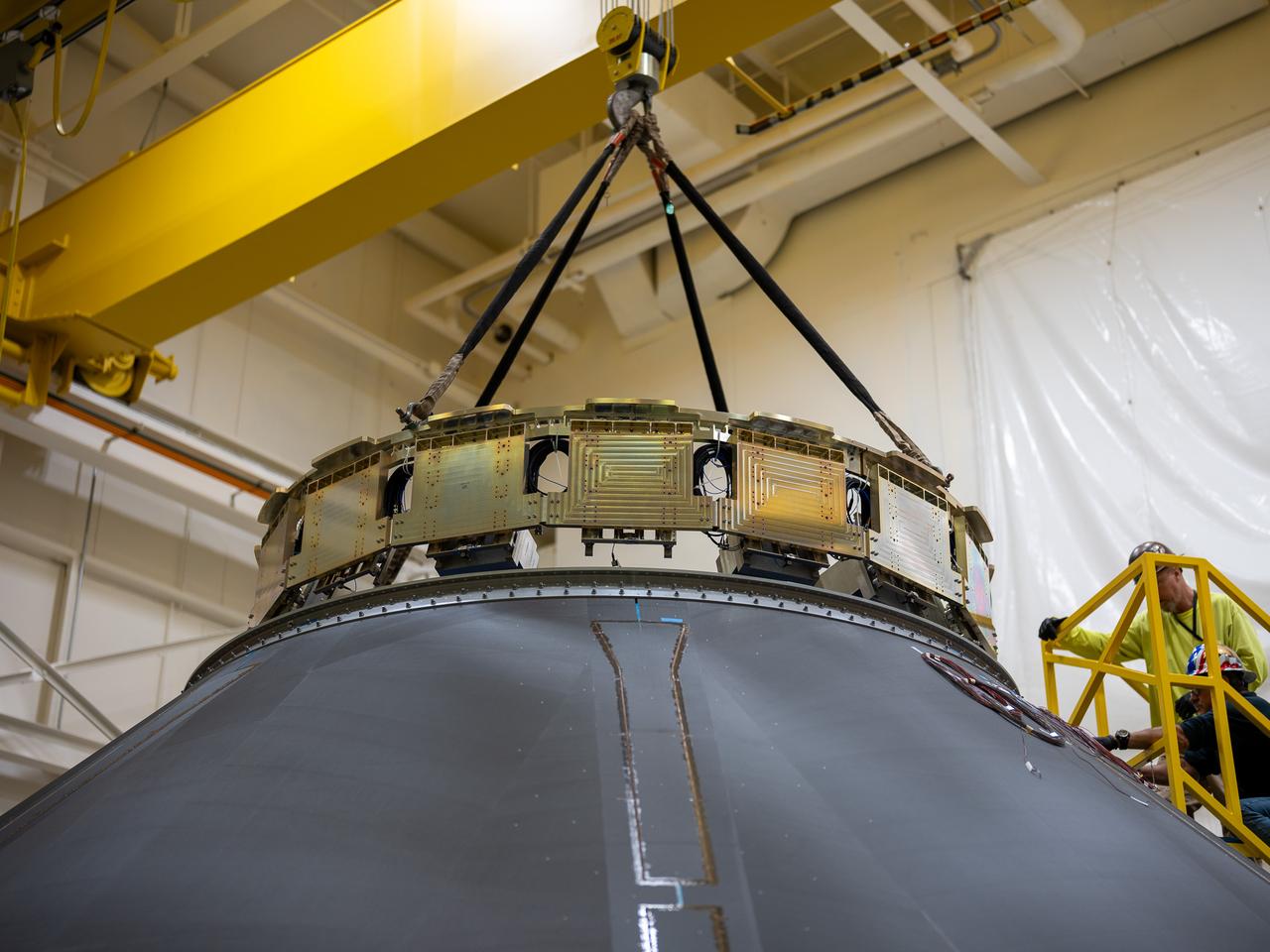
These photos and videos show how NASA manufactured and prepared to transport the payload adapter in February inside Building 4708 at NASA’s Marshall Space Flight Center in Huntsville, Alabama. Prior to moving the hardware for testing, teams installed the New Explorations Secondary Transport component, called the NEST, into the top of the engineering development unit. The NEST component will allow the hardware to hold a series of secondary payloads, or small satellites. The cone-shaped payload adapter is about 8.5 feet tall and features two metal rings and eight composite panels. The adapter, which will debut on NASA’s Artemis IV mission, is an evolution from the Orion stage adapter used in the Block 1 configuration of the rocket for the first three Artemis missions. It will be housed inside the universal stage adapter atop the rocket’s more powerful in-space stage, called the exploration upper stage. The payload adapter, like the launch vehicle stage adapter and the Orion stage adapter, is fully manufactured and tested at Marshall, which manages the SLS Program. NASA is working to land the first woman, first person of color, and its first international partner astronaut on the Moon under Artemis. SLS is part of NASA’s backbone for deep space exploration, along with the Orion spacecraft and Gateway in orbit around the Moon and commercial human landing systems, next-generational spacesuits, and rovers on the lunar surface. SLS is the only rocket that can send Orion, astronauts, and supplies to the Moon in a single launch.
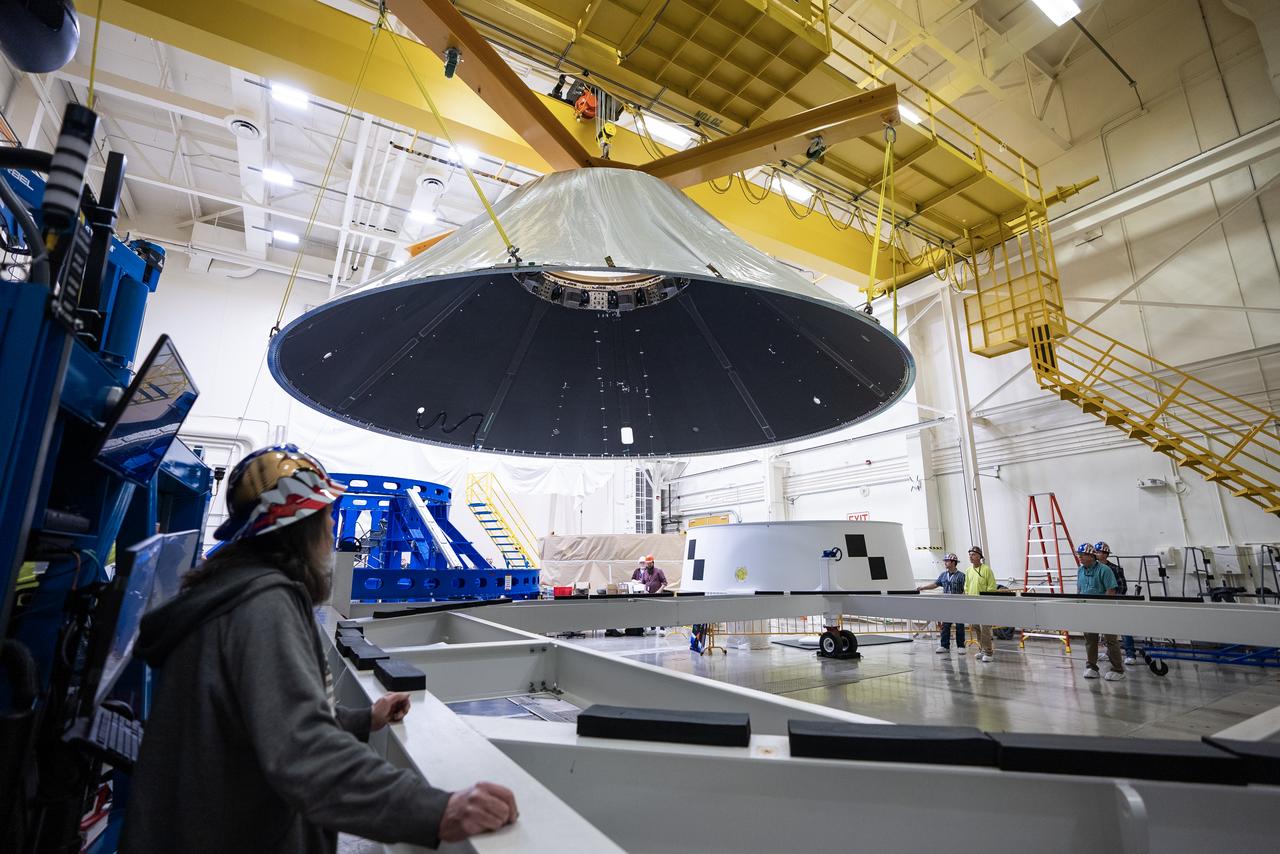
These photos and videos show how NASA manufactured and prepared to transport the payload adapter in February inside Building 4708 at NASA’s Marshall Space Flight Center in Huntsville, Alabama. Prior to moving the hardware for testing, teams installed the New Explorations Secondary Transport component, called the NEST, into the top of the engineering development unit. The NEST component will allow the hardware to hold a series of secondary payloads, or small satellites. The cone-shaped payload adapter is about 8.5 feet tall and features two metal rings and eight composite panels. The adapter, which will debut on NASA’s Artemis IV mission, is an evolution from the Orion stage adapter used in the Block 1 configuration of the rocket for the first three Artemis missions. It will be housed inside the universal stage adapter atop the rocket’s more powerful in-space stage, called the exploration upper stage. The payload adapter, like the launch vehicle stage adapter and the Orion stage adapter, is fully manufactured and tested at Marshall, which manages the SLS Program. NASA is working to land the first woman, first person of color, and its first international partner astronaut on the Moon under Artemis. SLS is part of NASA’s backbone for deep space exploration, along with the Orion spacecraft and Gateway in orbit around the Moon and commercial human landing systems, next-generational spacesuits, and rovers on the lunar surface. SLS is the only rocket that can send Orion, astronauts, and supplies to the Moon in a single launch.
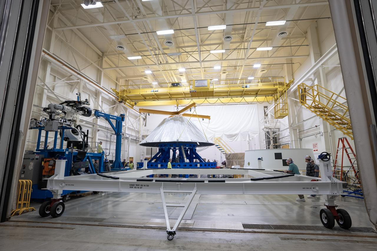
These photos and videos show how NASA manufactured and prepared to transport the payload adapter in February inside Building 4708 at NASA’s Marshall Space Flight Center in Huntsville, Alabama. Prior to moving the hardware for testing, teams installed the New Explorations Secondary Transport component, called the NEST, into the top of the engineering development unit. The NEST component will allow the hardware to hold a series of secondary payloads, or small satellites. The cone-shaped payload adapter is about 8.5 feet tall and features two metal rings and eight composite panels. The adapter, which will debut on NASA’s Artemis IV mission, is an evolution from the Orion stage adapter used in the Block 1 configuration of the rocket for the first three Artemis missions. It will be housed inside the universal stage adapter atop the rocket’s more powerful in-space stage, called the exploration upper stage. The payload adapter, like the launch vehicle stage adapter and the Orion stage adapter, is fully manufactured and tested at Marshall, which manages the SLS Program. NASA is working to land the first woman, first person of color, and its first international partner astronaut on the Moon under Artemis. SLS is part of NASA’s backbone for deep space exploration, along with the Orion spacecraft and Gateway in orbit around the Moon and commercial human landing systems, next-generational spacesuits, and rovers on the lunar surface. SLS is the only rocket that can send Orion, astronauts, and supplies to the Moon in a single launch.
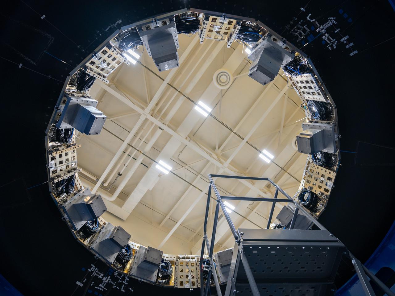
These photos and videos show how NASA manufactured and prepared to transport the payload adapter in February inside Building 4708 at NASA’s Marshall Space Flight Center in Huntsville, Alabama. Prior to moving the hardware for testing, teams installed the New Explorations Secondary Transport component, called the NEST, into the top of the engineering development unit. The NEST component will allow the hardware to hold a series of secondary payloads, or small satellites. The cone-shaped payload adapter is about 8.5 feet tall and features two metal rings and eight composite panels. The adapter, which will debut on NASA’s Artemis IV mission, is an evolution from the Orion stage adapter used in the Block 1 configuration of the rocket for the first three Artemis missions. It will be housed inside the universal stage adapter atop the rocket’s more powerful in-space stage, called the exploration upper stage. The payload adapter, like the launch vehicle stage adapter and the Orion stage adapter, is fully manufactured and tested at Marshall, which manages the SLS Program. NASA is working to land the first woman, first person of color, and its first international partner astronaut on the Moon under Artemis. SLS is part of NASA’s backbone for deep space exploration, along with the Orion spacecraft and Gateway in orbit around the Moon and commercial human landing systems, next-generational spacesuits, and rovers on the lunar surface. SLS is the only rocket that can send Orion, astronauts, and supplies to the Moon in a single launch.
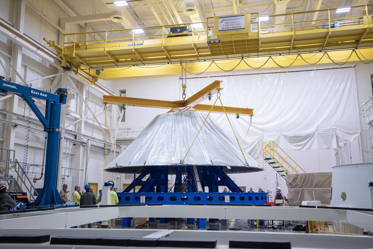
These photos and videos show how NASA manufactured and prepared to transport the payload adapter in February inside Building 4708 at NASA’s Marshall Space Flight Center in Huntsville, Alabama. Prior to moving the hardware for testing, teams installed the New Explorations Secondary Transport component, called the NEST, into the top of the engineering development unit. The NEST component will allow the hardware to hold a series of secondary payloads, or small satellites. The cone-shaped payload adapter is about 8.5 feet tall and features two metal rings and eight composite panels. The adapter, which will debut on NASA’s Artemis IV mission, is an evolution from the Orion stage adapter used in the Block 1 configuration of the rocket for the first three Artemis missions. It will be housed inside the universal stage adapter atop the rocket’s more powerful in-space stage, called the exploration upper stage. The payload adapter, like the launch vehicle stage adapter and the Orion stage adapter, is fully manufactured and tested at Marshall, which manages the SLS Program. NASA is working to land the first woman, first person of color, and its first international partner astronaut on the Moon under Artemis. SLS is part of NASA’s backbone for deep space exploration, along with the Orion spacecraft and Gateway in orbit around the Moon and commercial human landing systems, next-generational spacesuits, and rovers on the lunar surface. SLS is the only rocket that can send Orion, astronauts, and supplies to the Moon in a single launch.
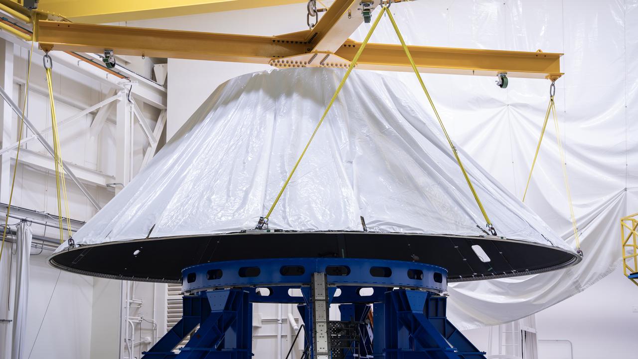
These photos and videos show how NASA manufactured and prepared to transport the payload adapter in February inside Building 4708 at NASA’s Marshall Space Flight Center in Huntsville, Alabama. Prior to moving the hardware for testing, teams installed the New Explorations Secondary Transport component, called the NEST, into the top of the engineering development unit. The NEST component will allow the hardware to hold a series of secondary payloads, or small satellites. The cone-shaped payload adapter is about 8.5 feet tall and features two metal rings and eight composite panels. The adapter, which will debut on NASA’s Artemis IV mission, is an evolution from the Orion stage adapter used in the Block 1 configuration of the rocket for the first three Artemis missions. It will be housed inside the universal stage adapter atop the rocket’s more powerful in-space stage, called the exploration upper stage. The payload adapter, like the launch vehicle stage adapter and the Orion stage adapter, is fully manufactured and tested at Marshall, which manages the SLS Program. NASA is working to land the first woman, first person of color, and its first international partner astronaut on the Moon under Artemis. SLS is part of NASA’s backbone for deep space exploration, along with the Orion spacecraft and Gateway in orbit around the Moon and commercial human landing systems, next-generational spacesuits, and rovers on the lunar surface. SLS is the only rocket that can send Orion, astronauts, and supplies to the Moon in a single launch.
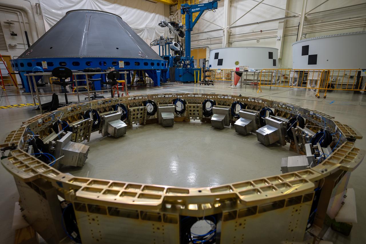
These photos and videos show how NASA manufactured and prepared to transport the payload adapter in February inside Building 4708 at NASA’s Marshall Space Flight Center in Huntsville, Alabama. Prior to moving the hardware for testing, teams installed the New Explorations Secondary Transport component, called the NEST, into the top of the engineering development unit. The NEST component will allow the hardware to hold a series of secondary payloads, or small satellites. The cone-shaped payload adapter is about 8.5 feet tall and features two metal rings and eight composite panels. The adapter, which will debut on NASA’s Artemis IV mission, is an evolution from the Orion stage adapter used in the Block 1 configuration of the rocket for the first three Artemis missions. It will be housed inside the universal stage adapter atop the rocket’s more powerful in-space stage, called the exploration upper stage. The payload adapter, like the launch vehicle stage adapter and the Orion stage adapter, is fully manufactured and tested at Marshall, which manages the SLS Program. NASA is working to land the first woman, first person of color, and its first international partner astronaut on the Moon under Artemis. SLS is part of NASA’s backbone for deep space exploration, along with the Orion spacecraft and Gateway in orbit around the Moon and commercial human landing systems, next-generational spacesuits, and rovers on the lunar surface. SLS is the only rocket that can send Orion, astronauts, and supplies to the Moon in a single launch.
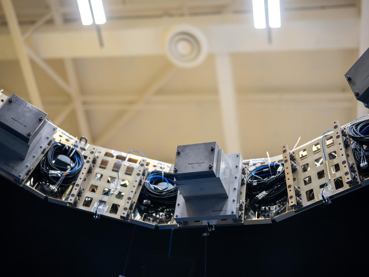
These photos and videos show how NASA manufactured and prepared to transport the payload adapter in February inside Building 4708 at NASA’s Marshall Space Flight Center in Huntsville, Alabama. Prior to moving the hardware for testing, teams installed the New Explorations Secondary Transport component, called the NEST, into the top of the engineering development unit. The NEST component will allow the hardware to hold a series of secondary payloads, or small satellites. The cone-shaped payload adapter is about 8.5 feet tall and features two metal rings and eight composite panels. The adapter, which will debut on NASA’s Artemis IV mission, is an evolution from the Orion stage adapter used in the Block 1 configuration of the rocket for the first three Artemis missions. It will be housed inside the universal stage adapter atop the rocket’s more powerful in-space stage, called the exploration upper stage. The payload adapter, like the launch vehicle stage adapter and the Orion stage adapter, is fully manufactured and tested at Marshall, which manages the SLS Program. NASA is working to land the first woman, first person of color, and its first international partner astronaut on the Moon under Artemis. SLS is part of NASA’s backbone for deep space exploration, along with the Orion spacecraft and Gateway in orbit around the Moon and commercial human landing systems, next-generational spacesuits, and rovers on the lunar surface. SLS is the only rocket that can send Orion, astronauts, and supplies to the Moon in a single launch.
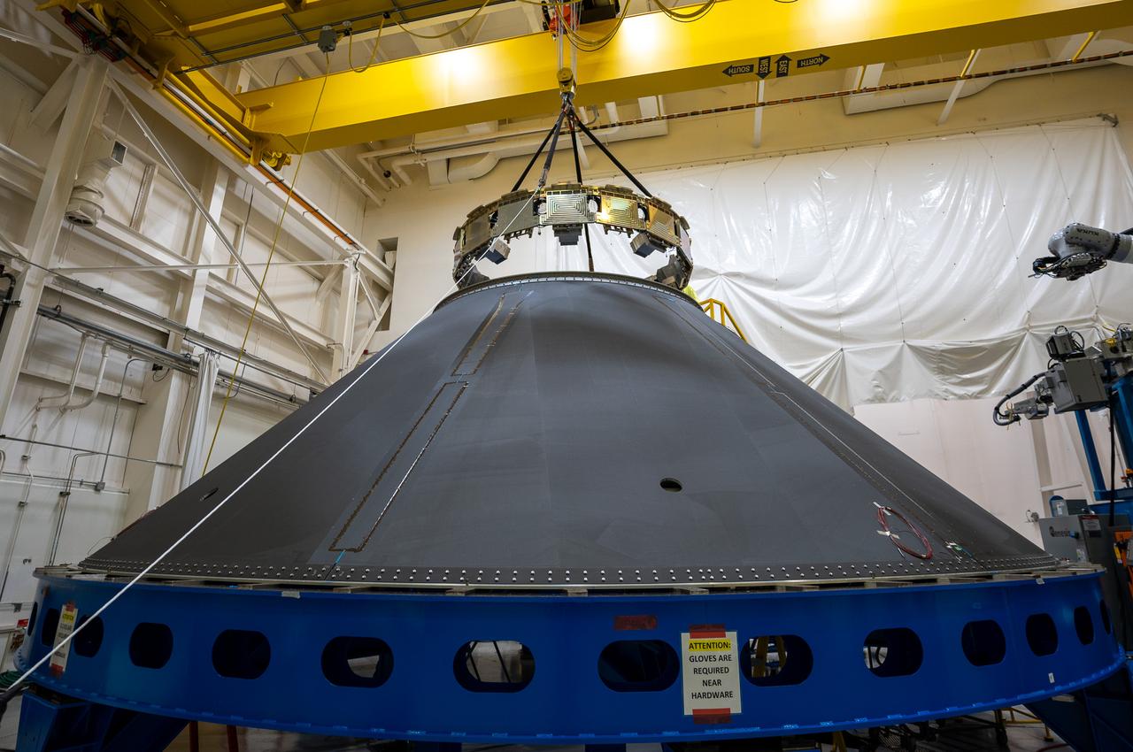
These photos and videos show how NASA manufactured and prepared to transport the payload adapter in February inside Building 4708 at NASA’s Marshall Space Flight Center in Huntsville, Alabama. Prior to moving the hardware for testing, teams installed the New Explorations Secondary Transport component, called the NEST, into the top of the engineering development unit. The NEST component will allow the hardware to hold a series of secondary payloads, or small satellites. The cone-shaped payload adapter is about 8.5 feet tall and features two metal rings and eight composite panels. The adapter, which will debut on NASA’s Artemis IV mission, is an evolution from the Orion stage adapter used in the Block 1 configuration of the rocket for the first three Artemis missions. It will be housed inside the universal stage adapter atop the rocket’s more powerful in-space stage, called the exploration upper stage. The payload adapter, like the launch vehicle stage adapter and the Orion stage adapter, is fully manufactured and tested at Marshall, which manages the SLS Program. NASA is working to land the first woman, first person of color, and its first international partner astronaut on the Moon under Artemis. SLS is part of NASA’s backbone for deep space exploration, along with the Orion spacecraft and Gateway in orbit around the Moon and commercial human landing systems, next-generational spacesuits, and rovers on the lunar surface. SLS is the only rocket that can send Orion, astronauts, and supplies to the Moon in a single launch.
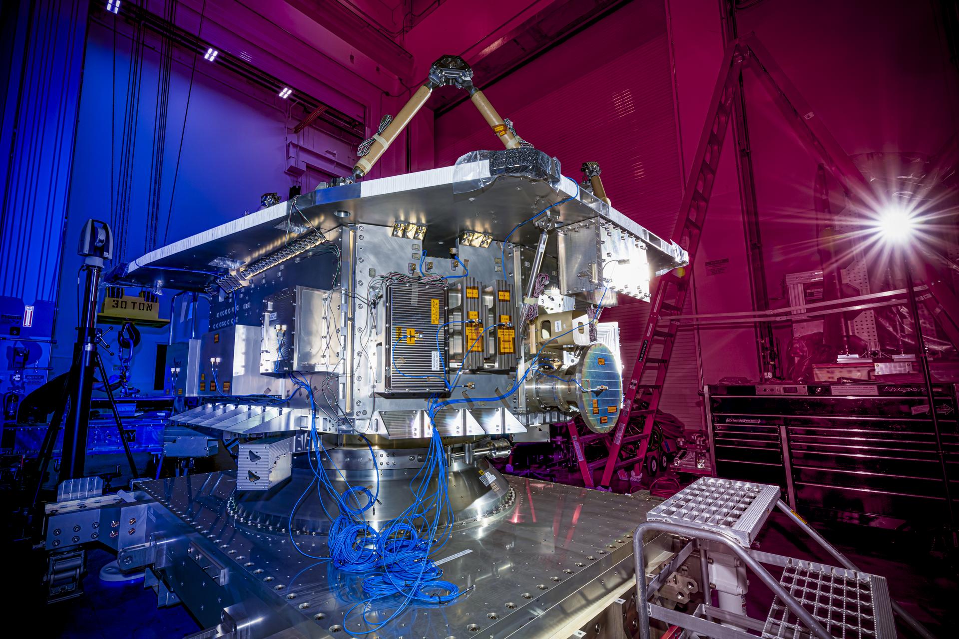
The bus structure of the Near-Earth Object (NEO) Surveyor spacecraft underwent testing at BAE Systems Space & Mission Systems in Boulder, Colorado, in August 2025. NEO Surveyor’s bus houses the power, propulsion, avionics, and communication subsystems, which are isolated from the spacecraft’s telescope and sensitive detectors. When all components are assembled, a large sunshade will be attached to the side of the bus, blocking the Sun’s glare from entering the telescope. With an aperture of nearly 20 inches (50 centimeters), the telescope features detectors sensitive to two infrared wavelengths in which near-Earth objects re-radiate solar heat. The instrument enclosure is designed to ensure heat produced by the spacecraft and instrument during operations doesn’t interfere with its infrared observations. Targeting launch in late 2027, the NEO Surveyor mission is led by Professor Amy Mainzer at the University of California, Los Angeles for NASA’s Planetary Defense Coordination Office and is being managed by the agency’s Jet Propulsion Laboratory in Southern California for the Planetary Missions Program Office at NASA’s Marshall Space Flight Center in Huntsville, Alabama. BAE Systems Space & Mission Systems and the Space Dynamics Laboratory in Logan, Utah, and Teledyne are among the companies that were contracted to build the spacecraft and its instrumentation. The Laboratory for Atmospheric and Space Physics at the University of Colorado Boulder will support operations, and IPAC at Caltech in Pasadena, California, is responsible for producing some of the mission’s data products. Caltech manages JPL for NASA. More information about NEO Surveyor is available at: https://science.nasa.gov/mission/neo-surveyor/