CAPE CANAVERAL, Fla. -- Inside the Launch Equipment Test Facility at NASA’s Kennedy Space in Florida, a second firing of the escape hold down post has occurred during a pyrotechnic bolt test on the Orion ground test vehicle.      Lockheed Martin performed tests over a series of days on the explosive bolts that separate Orion from the launch abort system. Data was collected on the effect of shock waves on Orion during the explosive bolt separation. Orion is the exploration spacecraft designed to carry crews to space beyond low Earth orbit. It will provide emergency abort capability, sustain the crew during the space travel and provide safe re-entry from deep space return velocities. The first unpiloted test flight of the Orion is scheduled to launch in 2014 atop a Delta IV rocket and in 2017 on a Space Launch System rocket. For more information, visit http://www.nasa.gov/orion. Photo credit: NASA/Jim Grossmann
KSC-2013-3008
CAPE CANAVERAL, Fla. -- The Orion ground test vehicle sits on a test stand in the Launch Equipment Test Facility at NASA’s Kennedy Space Center in Florida while engineers and technicians prepare it for a pyrotechnic bolt test.     Lockheed Martin performed tests over a series of days on the explosive bolts that separate Orion from the launch abort system. Data was collected on the effect of shock waves on Orion during the explosive bolt separation. Orion is the exploration spacecraft designed to carry crews to space beyond low Earth orbit. It will provide emergency abort capability, sustain the crew during the space travel and provide safe re-entry from deep space return velocities. The first unpiloted test flight of the Orion is scheduled to launch in 2014 atop a Delta IV rocket and in 2017 on a Space Launch System rocket. For more information, visit http://www.nasa.gov/orion. Photo credit: NASA/Jim Grossmann
KSC-2013-3007
ISS040-E-099850 (18 Aug. 2014) --- NASA astronaut Reid Wiseman, Expedition 40 crew member, performs routine in-flight maintenance in the Tranquility node of the International Space Station.
Node 3 bolt removal
Marshall Space Flight Center (MSFC) has developed a specially-designed nut, called the Quick-Connect Nut, for quick and easy assembly of components in the harsh environment of space, as in assembly of International Space Station. The design permits nuts to be installed simply by pushing them onto standard bolts, then giving a quick twist. To remove, they are unscrewed like conventional nuts. Possible applications include the mining industry for erecting support barriers, assembling underwater oil drilling platforms, fire-fighting equipment, scaffolding, assembly-line machinery, industrial cranes, and even changing lug nuts on race cars. The speed of assembly can make the difference between life and death in different aspects of life on Earth.
Benefit from NASA
Documentation of retainers, springs and screws used during Expedition 35 Ku Communications (Comm) Unit fastener modifications. Parts are attached to Kapton tape.
Ku Comm Unit Bolt Modification
Ares I-X Deputy Mission Manager Jon Cowart shows a space shuttle solid rocket booster (SRB) separation bolt during a two-day NASA Tweetup event held at NASA's Kennedy Space Center in Cape Canaveral, Fla, Sunday, Nov. 15, 2009. NASA Twitter followers in attendance will have the opportunity to take a tour of NASA's Kennedy Space Center, view the STS-129 space shuttle launch and speak with shuttle technicians, engineers, astronauts and managers.  Photo Credit: (NASA/Carla Cioffi)
STS-129 Tweetup
STS088-359-037  (4-15 Dec. 1998) --- Astronaut Nancy J. Currie and  cosmonaut Sergei K. Krikalev, both mission specialists, use rechargeable power tools to manipulate nuts and bolts on the Russian-built Zarya module.  Astronaut Robert D. Cabana, mission commander, translates along the  rail network in the background.  The six STS-88 crew members had earlier entered the module through the U.S.-built Unity connecting module.  Rails, straps and tools indicate the crewmembers had been working awhile when this photo was taken.  Krikalev, representing the Russian Space Agency (RSA), has been assigned as a member of the three-man initial International Space Station (ISS) crew.
Currie and Krikalev pull launch restraint bolts in the FGB/Zarya module
KENNEDY SPACE CENTER, FLA.  - In the Vehicle Assembly Building, Lead Technician Todd Reeves, with United Space Alliance, moves a bolt catcher into place between the Solid Rocket Booster and left and the External Tank at right.A bolt catcher is a vertical bolt mechanism at the forward end of the External Tank that attaches each booster to the tank. At approximately two minutes into launch, SRB separation begins when pyrotechnic devices fire to break the 25-inch, 62-pound steel bolts. One half of the bolt is caught in canister-like 'bolt catchers' located on the tank; the other half remains with the boosters. Discovery is flying with a modified bolt catcher, which was upgraded from a two-piece welded design to a one-piece, machine-made design as part of NASA's effort to return to safe, reliable spaceflight.  Eliminating the weld makes a structurally stronger bolt catcher design. Though the bolt catcher is mounted on the External Tank, it is considered part of the Solid Rocket Booster element design. It is built by Summa Technologies, Inc. in Huntsville, Ala., insulated at Lockheed Martin’s Michoud Assembly Facility in New Orleans, and installed on the External Tank at KSC.
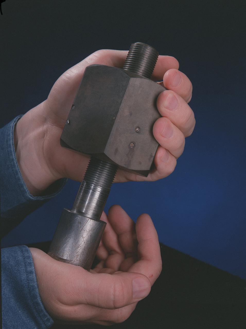
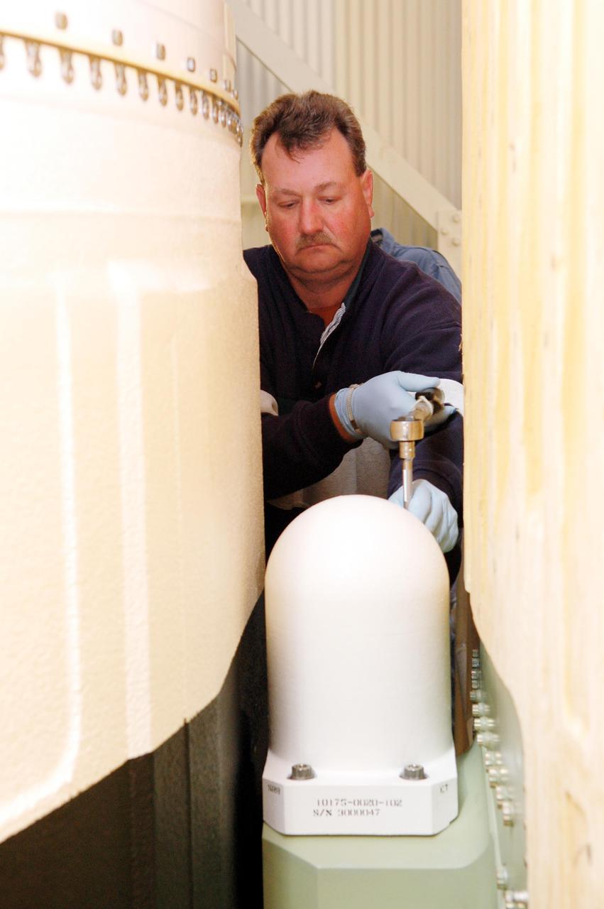
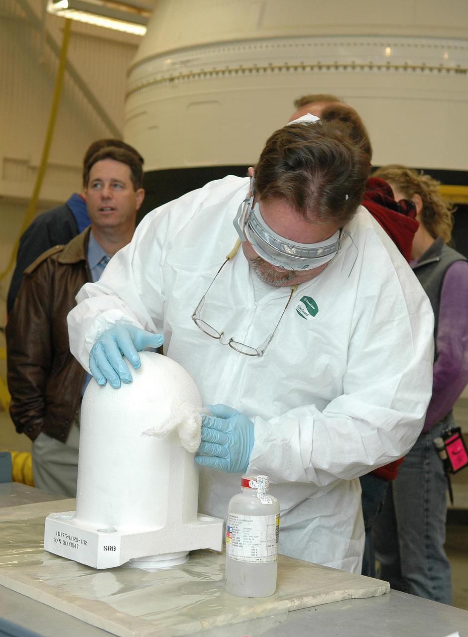
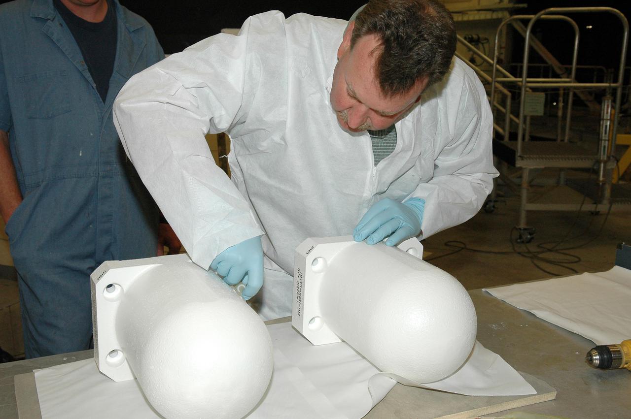
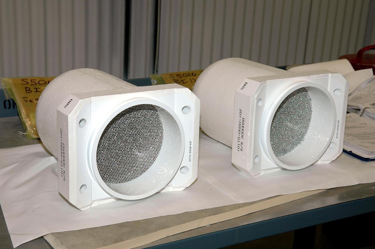
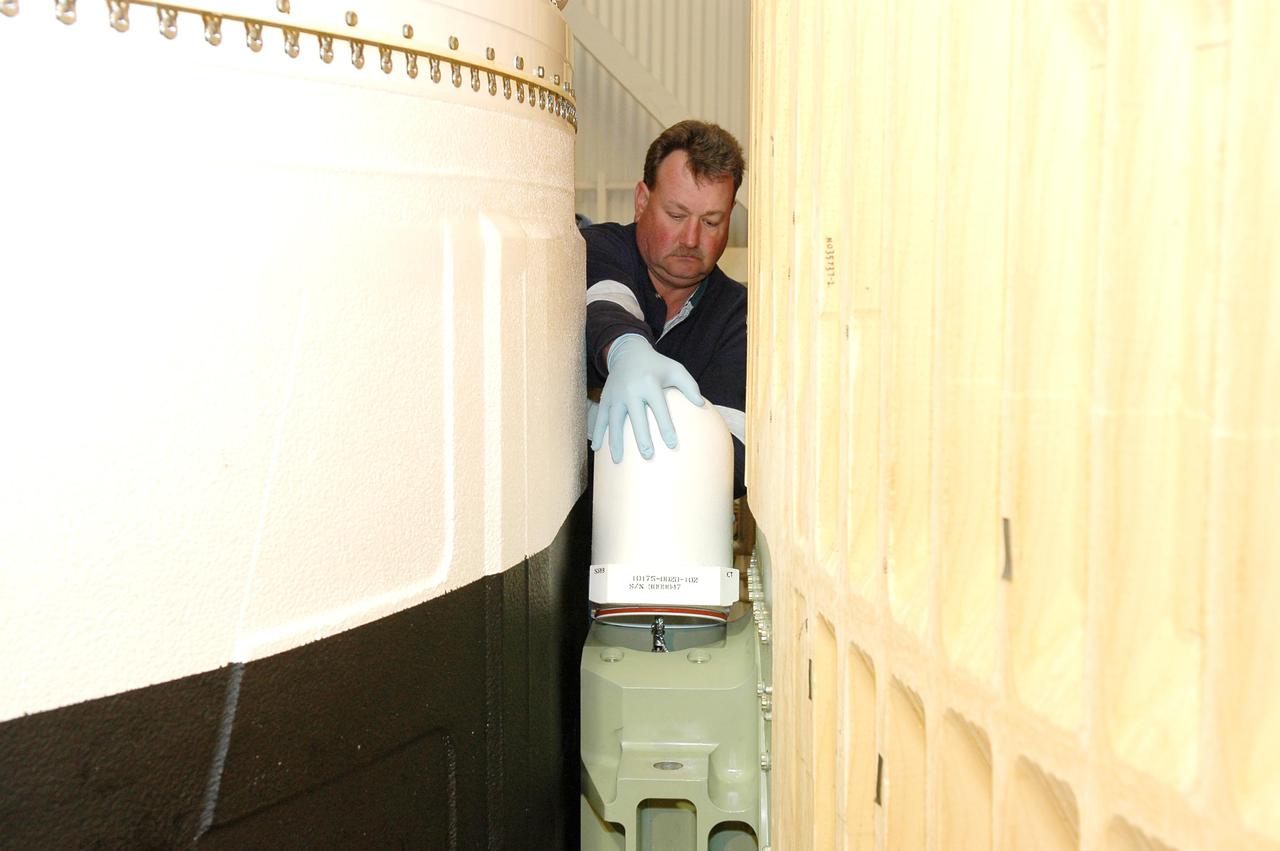
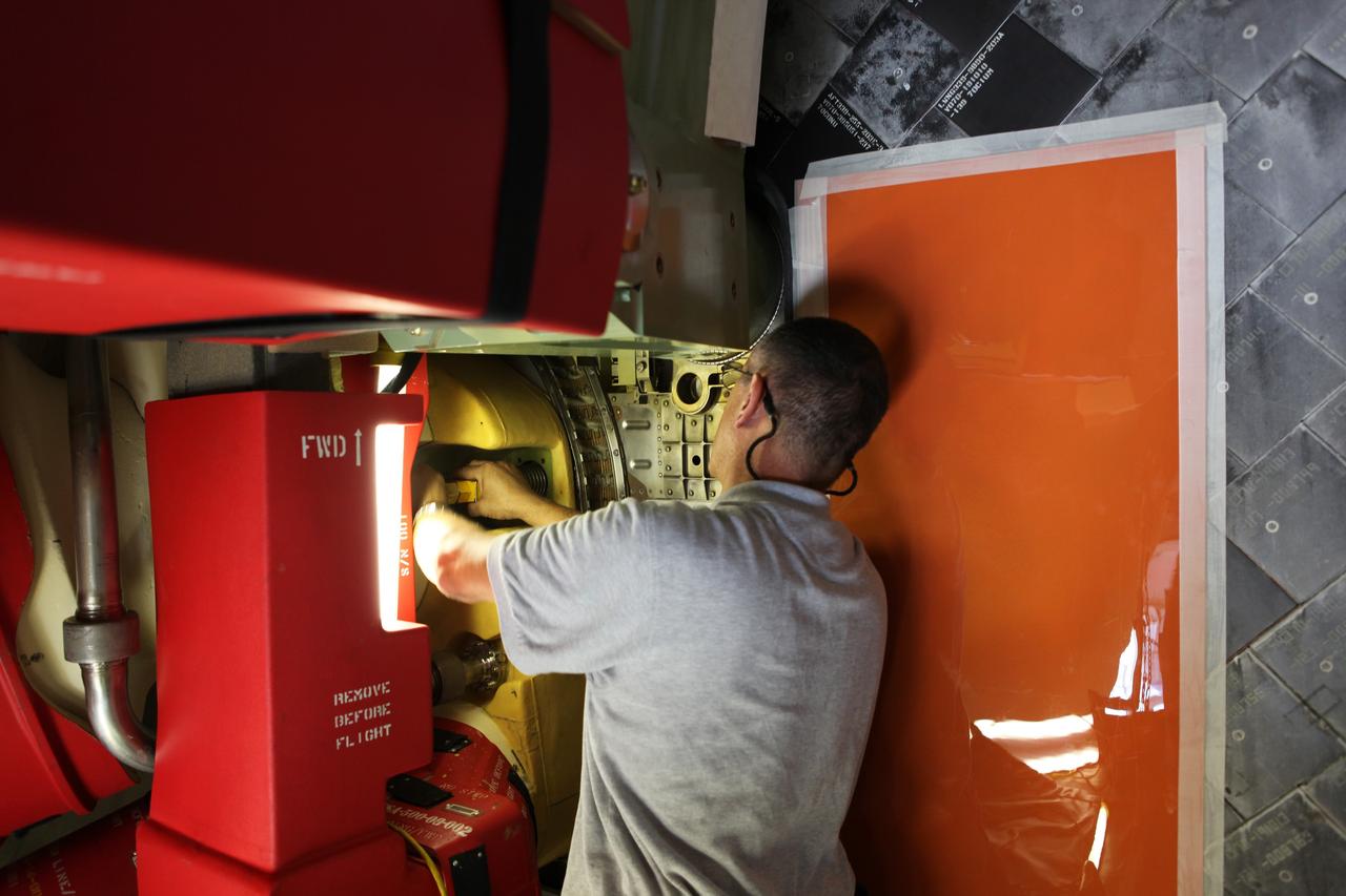
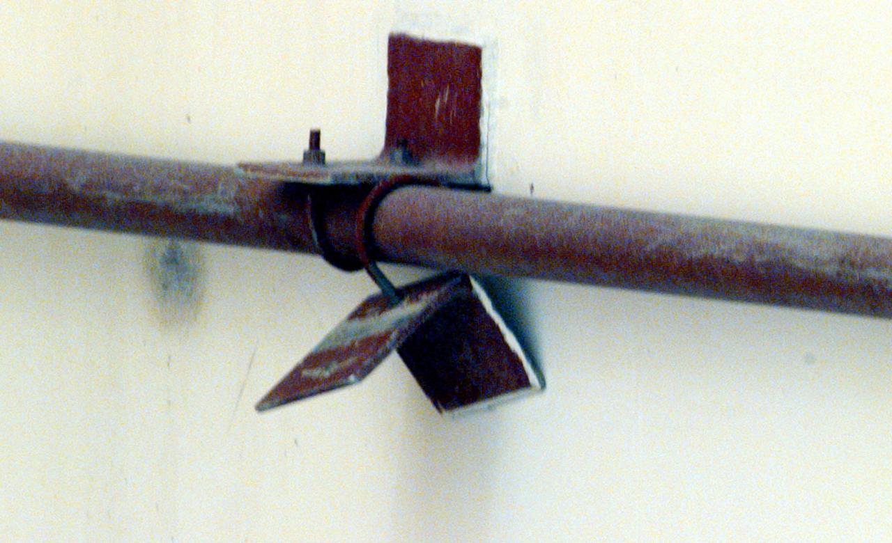
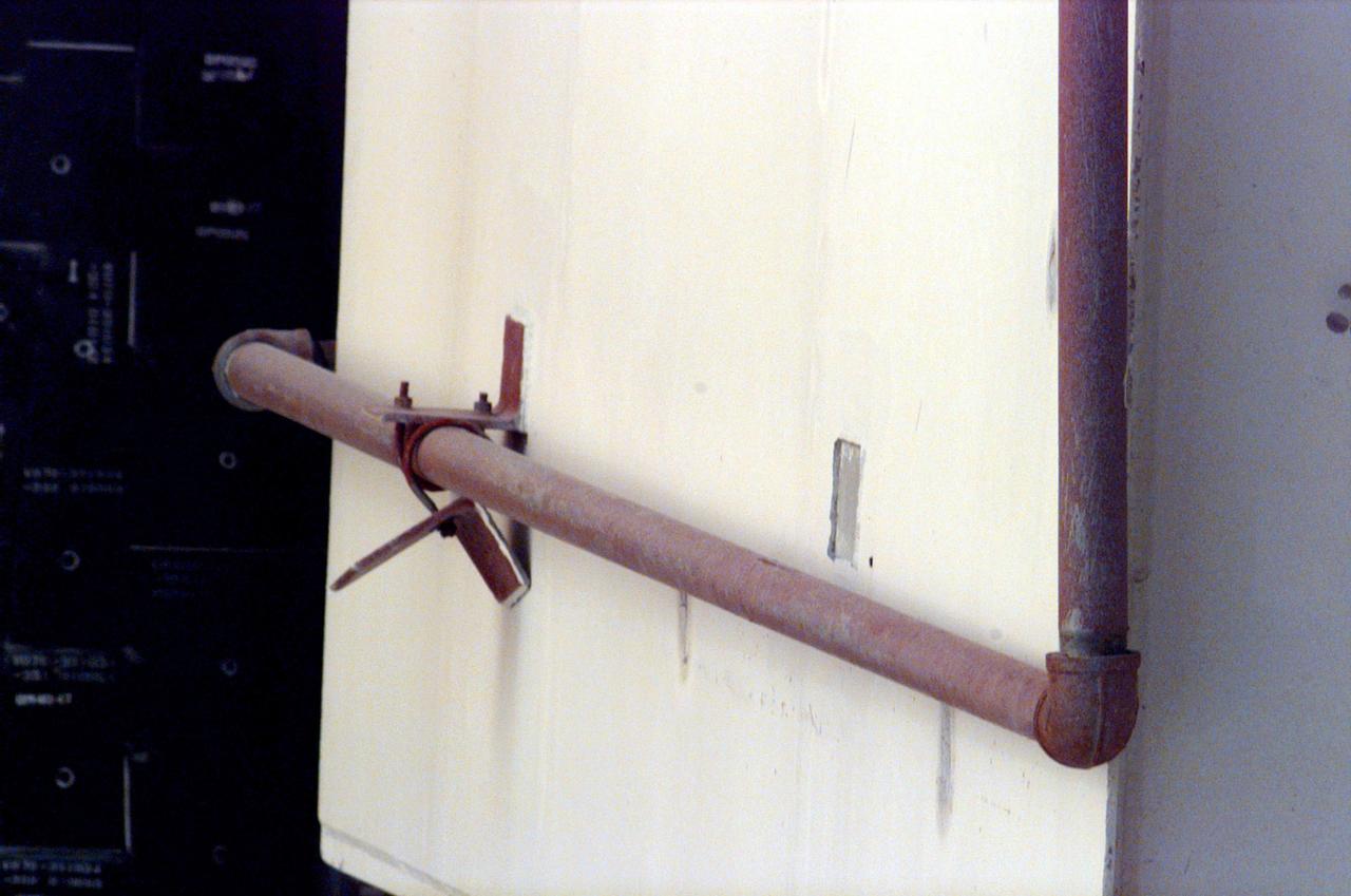
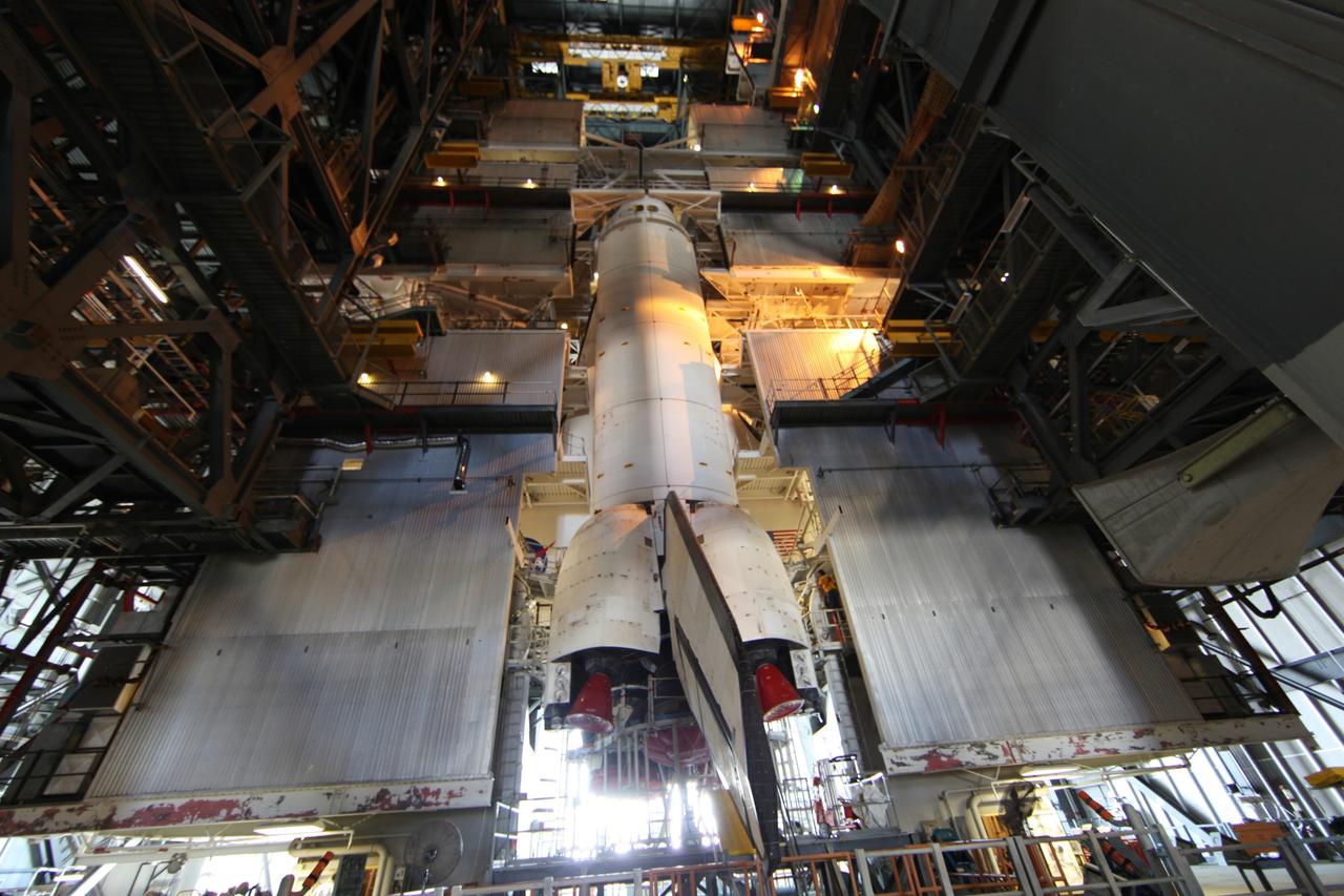
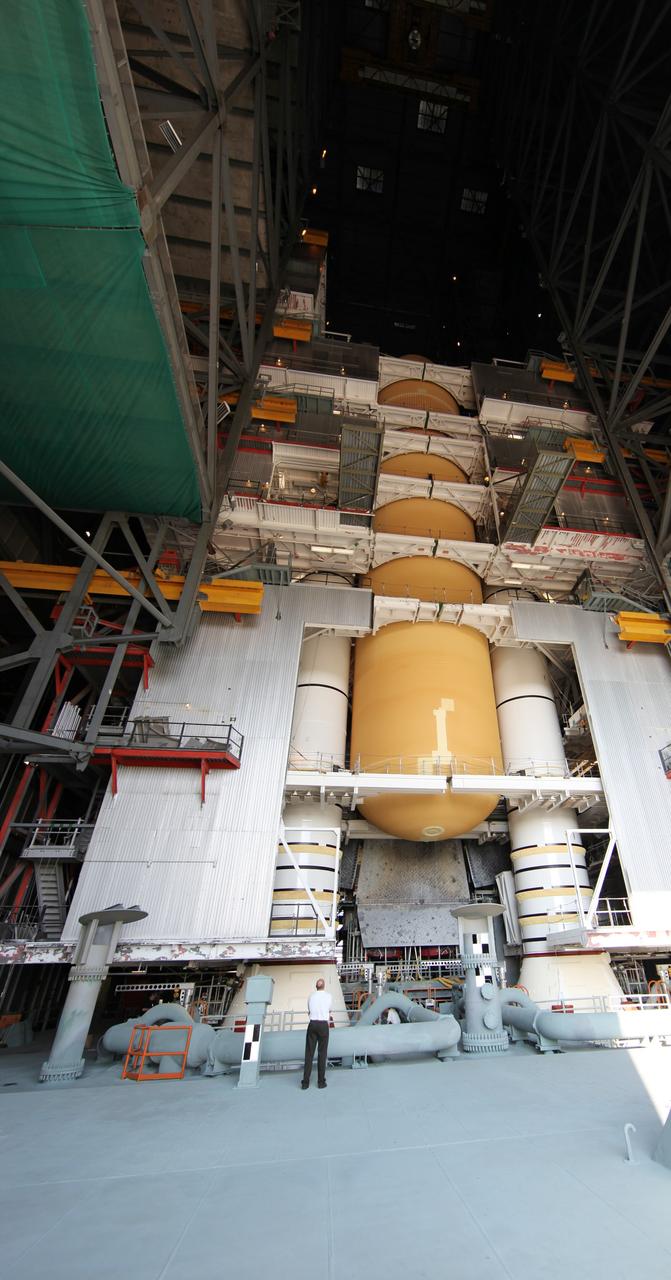
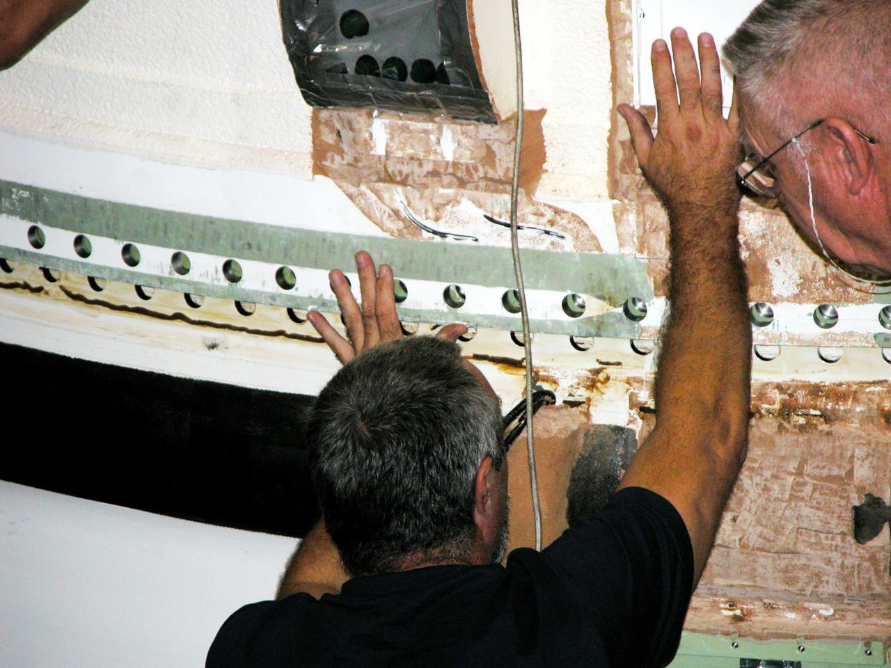
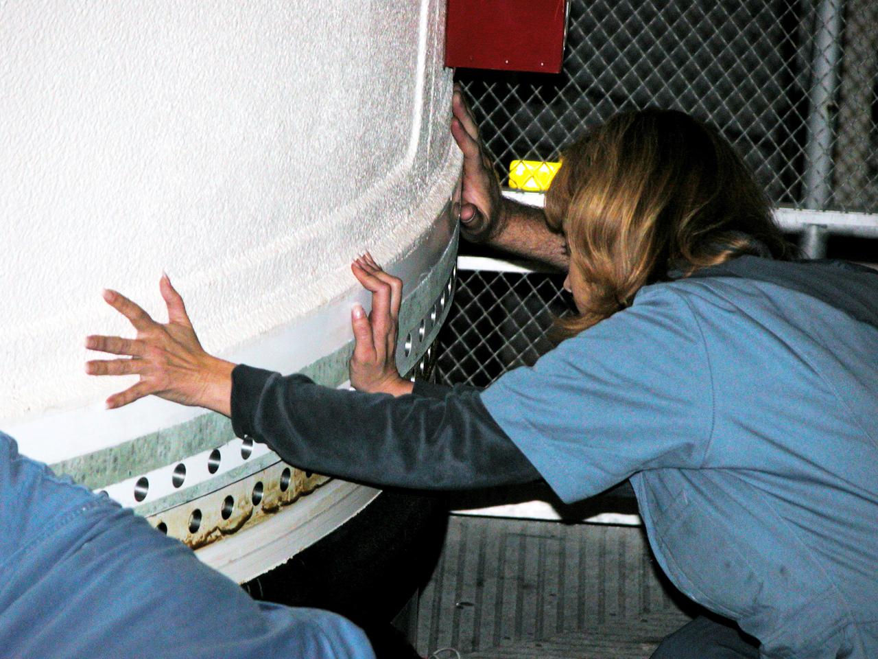
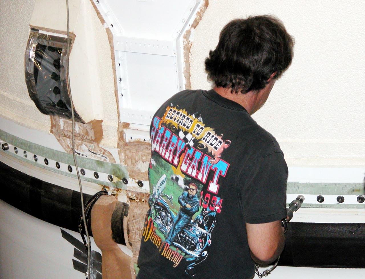
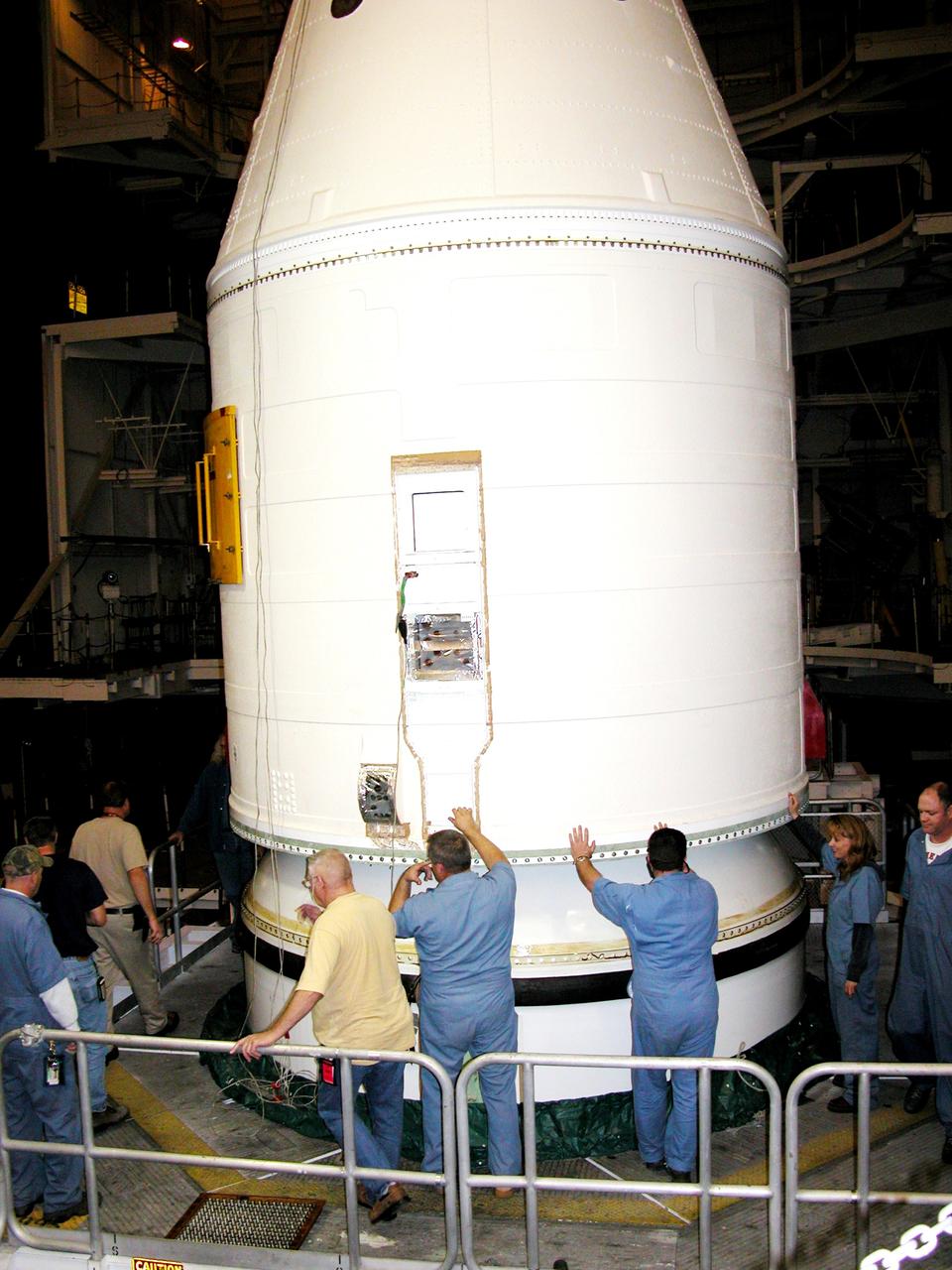
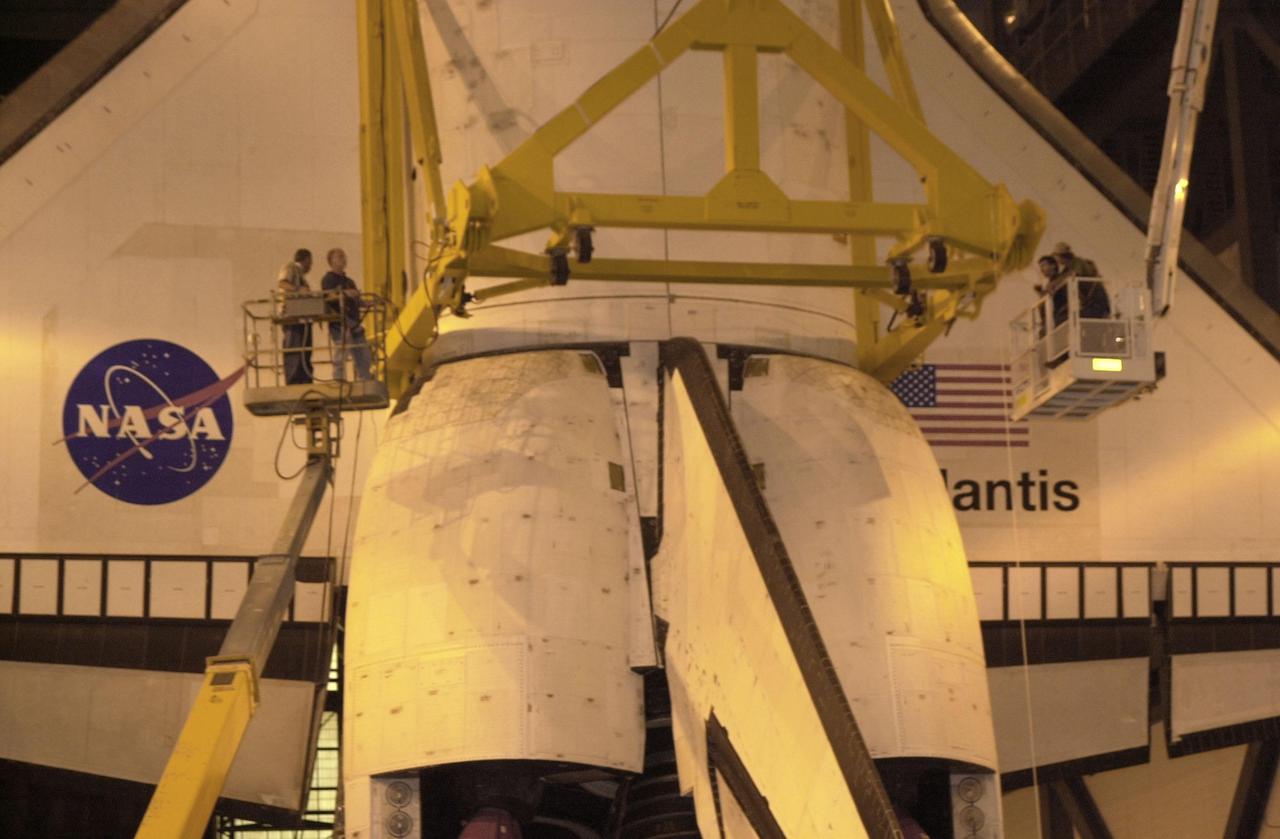
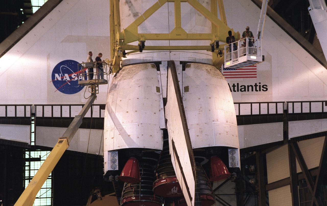
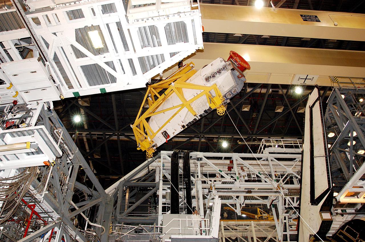
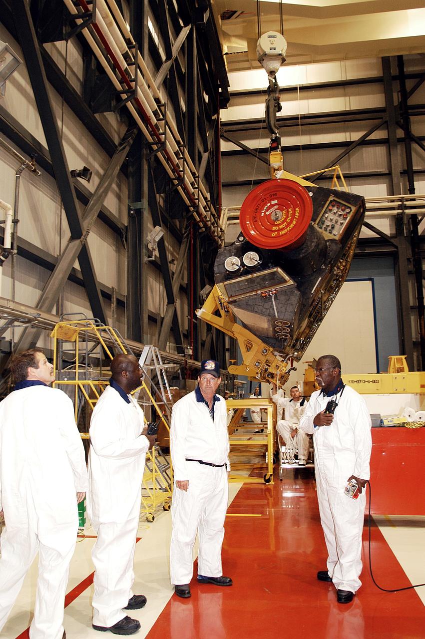
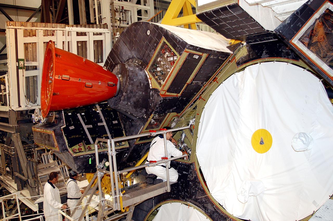
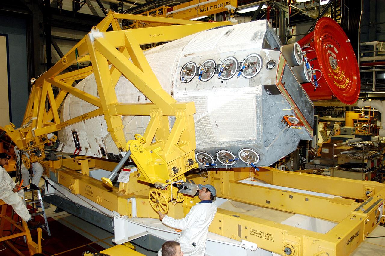
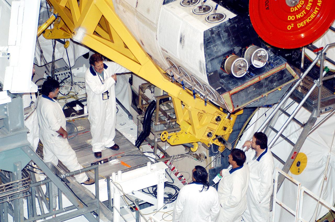
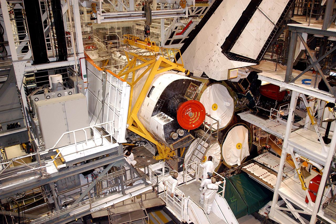
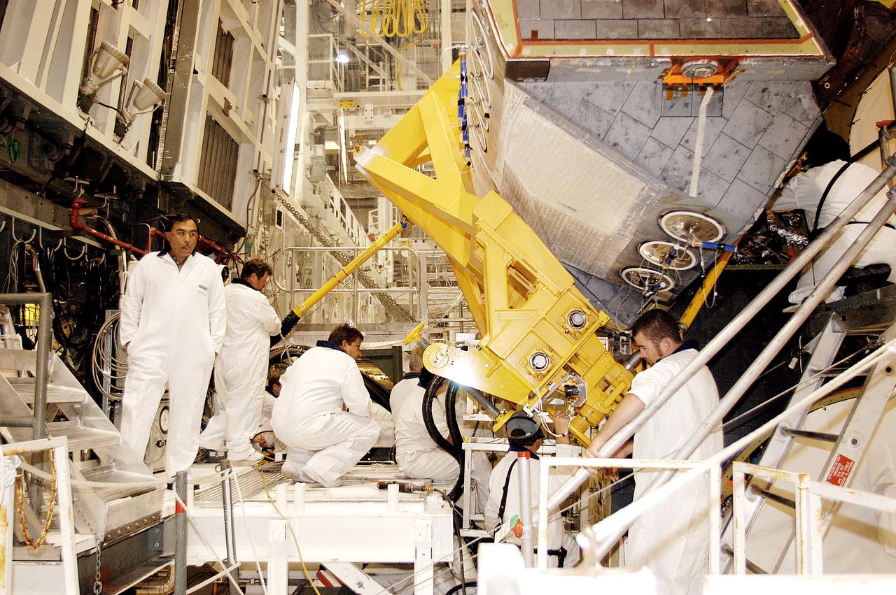
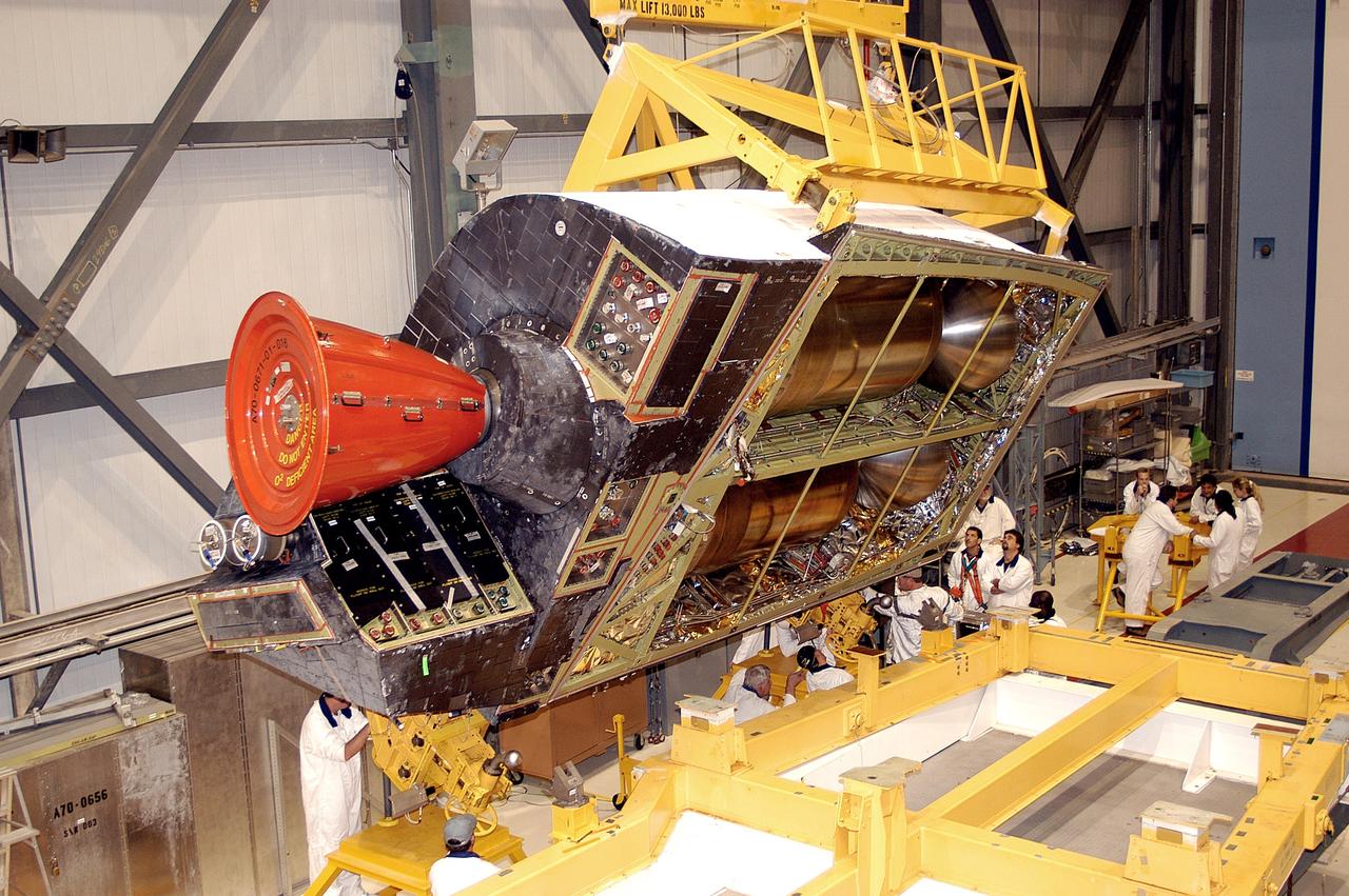
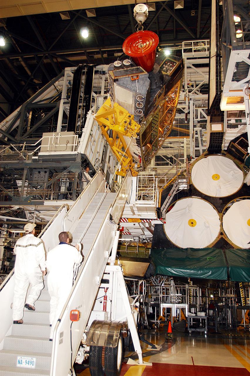
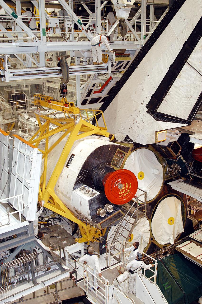
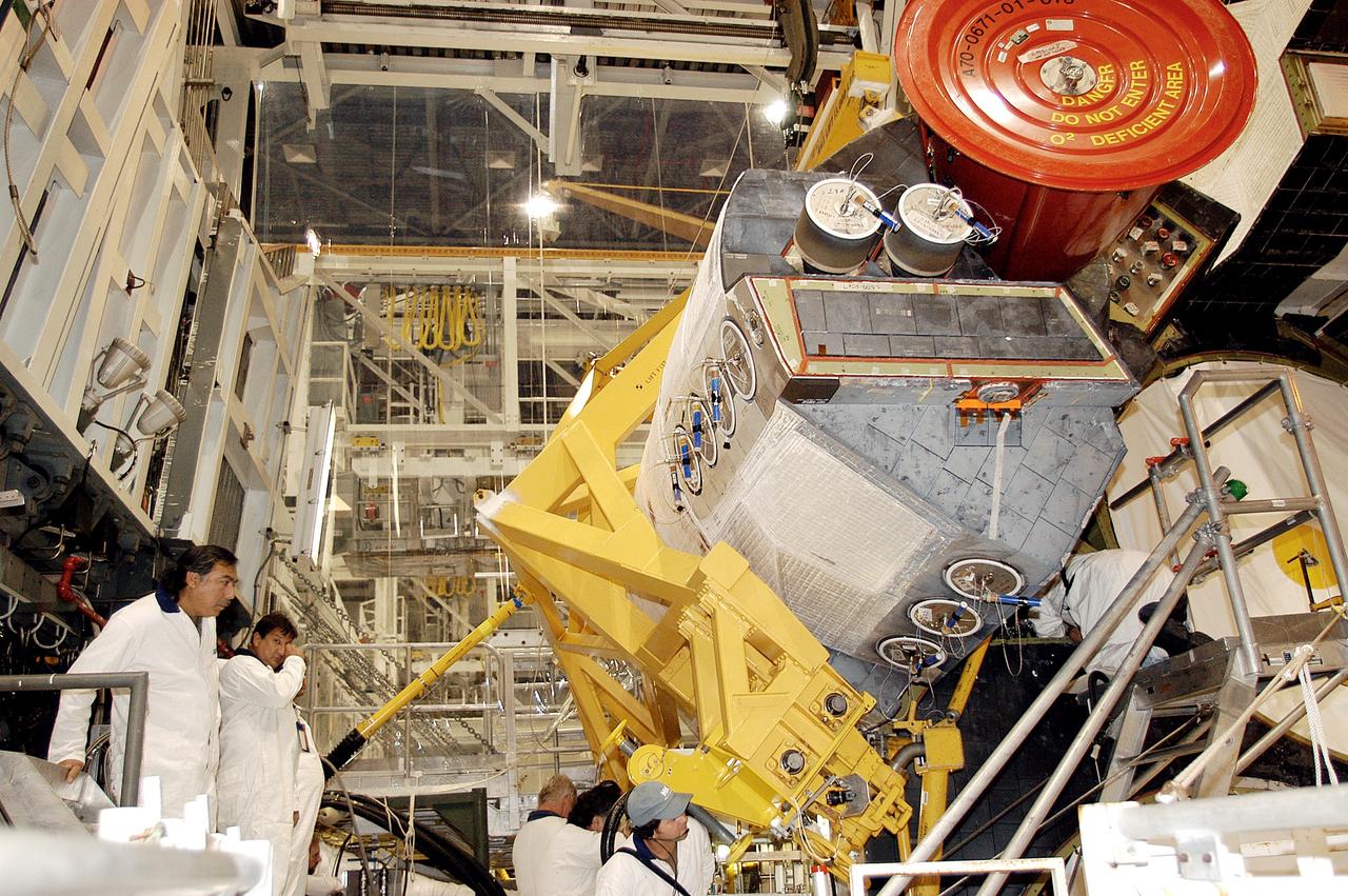
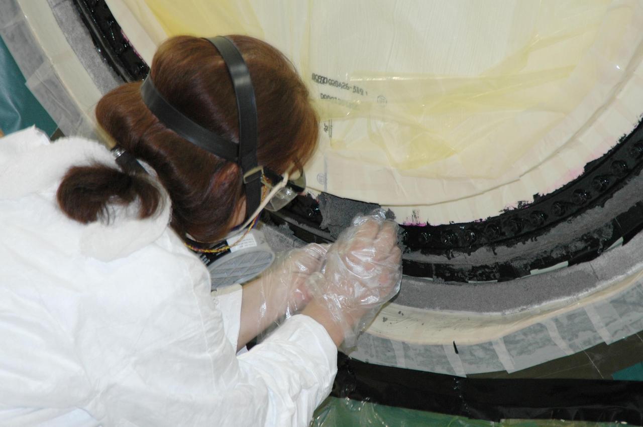
KSC-05pd-0383
KENNEDY SPACE CENTER, FLA.  - In the Vehicle Assembly Building, Senior Technician Kevin Reagan, with United Space Alliance, prepares one of two bolt catchers for installation on orbiter Discovery’s External Tank.  A bolt catcher is a vertical bolt mechanism at the forward end of the External Tank that attaches each booster to the tank. At approximately two minutes into launch, SRB separation begins when pyrotechnic devices fire to break the 25-inch, 62-pound steel bolts. One half of the bolt is caught in canister-like 'bolt catchers' located on the tank; the other half remains with the boosters. Discovery is flying with a modified bolt catcher, which was upgraded from a two-piece welded design to a one-piece, machine-made design as part of NASA's effort to return to safe, reliable spaceflight.  Eliminating the weld makes a structurally stronger bolt catcher design. Though the bolt catcher is mounted on the External Tank, it is considered part of the Solid Rocket Booster element design. It is built by Summa Technologies, Inc. in Huntsville, Ala., insulated at Lockheed Martin’s Michoud Assembly Facility in New Orleans, and installed on the External Tank at KSC.
KSC-05pd-0382
KENNEDY SPACE CENTER, FLA.  - These two bolt catchers are ready for installation on orbiter Discovery’s External Tank.  A bolt catcher is a vertical bolt mechanism at the forward end of the External Tank that attaches each booster to the tank. At approximately two minutes into launch, SRB separation begins when pyrotechnic devices fire to break the 25-inch, 62-pound steel bolts. One half of the bolt is caught in canister-like 'bolt catchers' located on the tank; the other half remains with the boosters. Discovery is flying with a modified bolt catcher, which was upgraded from a two-piece welded design to a one-piece, machine-made design as part of NASA's effort to return to safe, reliable spaceflight.  Eliminating the weld makes a structurally stronger bolt catcher design. Though the bolt catcher is mounted on the External Tank, it is considered part of the Solid Rocket Booster element design. It is built by Summa Technologies, Inc. in Huntsville, Ala., insulated at Lockheed Martin’s Michoud Assembly Facility in New Orleans, and installed on the External Tank at KSC.
KSC-05pd-0380
KENNEDY SPACE CENTER, FLA.  - In the Vehicle Assembly Building, Lead Technician Todd Reeves, with United Space Alliance, attaches one of two bolt catchers on orbiter Discovery’s External Tank.  A bolt catcher is a vertical bolt mechanism at the forward end of the External Tank that attaches each booster to the tank. At approximately two minutes into launch, SRB separation begins when pyrotechnic devices fire to break the 25-inch, 62-pound steel bolts. One half of the bolt is caught in canister-like 'bolt catchers' located on the tank; the other half remains with the boosters. Discovery is flying with a modified bolt catcher, which was upgraded from a two-piece welded design to a one-piece, machine-made design as part of NASA's effort to return to safe, reliable spaceflight.  Eliminating the weld makes a structurally stronger bolt catcher design. Though the bolt catcher is mounted on the External Tank, it is considered part of the Solid Rocket Booster element design. It is built by Summa Technologies, Inc. in Huntsville, Ala., insulated at Lockheed Martin’s Michoud Assembly Facility in New Orleans, and installed on the External Tank at KSC.
KSC-05pd-0384
KENNEDY SPACE CENTER, FLA.  - In the Vehicle Assembly Building, workers prepare these two bolt catchers for installation on orbiter Discovery’s External Tank.   A bolt catcher is a vertical bolt mechanism at the forward end of the External Tank that attaches each booster to the tank. At approximately two minutes into launch, SRB separation begins when pyrotechnic devices fire to break the 25-inch, 62-pound steel bolts. One half of the bolt is caught in canister-like 'bolt catchers' located on the tank; the other half remains with the boosters. Discovery is flying with a modified bolt catcher, which was upgraded from a two-piece welded design to a one-piece, machine-made design as part of NASA's effort to return to safe, reliable spaceflight.  Eliminating the weld makes a structurally stronger bolt catcher design. Though the bolt catcher is mounted on the External Tank, it is considered part of the Solid Rocket Booster element design. It is built by Summa Technologies, Inc. in Huntsville, Ala., insulated at Lockheed Martin’s Michoud Assembly Facility in New Orleans, and installed on the External Tank at KSC.
KSC-05pd-0381
KENNEDY SPACE CENTER, FLA. -- A bolt is shown in the lower central part of the photo. It is visible as a dark circle with a shadow surrounding it inside a larger silvery circle. The bolt extends above the surface 2-1/4 inches, causing the shadow.; The photo was taken at launch of Space Shuttle Atlantis on mission STS-106.
KSC-00padig036
KENNEDY SPACE CENTER, FLA. -- A bolt is shown in the lower central part of the photo. It is visible as a dark circle with a shadow surrounding it inside a larger silvery circle. The bolt extends above the surface 2-1/4 inches, causing the shadow.; The photo was taken at launch of Space Shuttle Atlantis on mission STS-106.
KSC00padig036
The logo of NASA's Jet Propulsion Laboratory has roamed Mars since the September 1997 landing of very first rover, Sojourner, part of the Mars Pathfinder mission. This close-up view of the JPL logo – bolted to the chassis of NASA's Perseverance – was acquired on June 28, 2025 (the 1,548th day, or sol, of its mission to Mars), by the rover's WATSON (Wide Angle Topographic Sensor for Operations and eNgineering) imager.  https://photojournal.jpl.nasa.gov/catalog/PIA26580
JPL on the Red Planet
CAPE CANAVERAL, Fla. -- At NASA's Kennedy Space Center in Florida, a Vehicle Assembly Building technician adjusts a left-side main separation bolt that attaches the bottom of space shuttle Discovery to its external fuel tank. As technicians were attaching the bolt Sept. 10, a bolt nut slipped back into Discovery's aft compartment. To retrieve it, technicians entered Discovery’s aft section through an access door. They then moved the nut back into position to finish attaching the bolt, which is used to separate Discovery from the external tank once the shuttle is in orbit. Discovery is scheduled to roll out to Launch Pad 39A later this month for its STS-133 launch to the International Space Station.    Targeted to lift off Nov. 1, Discovery will take the Permanent Multipurpose Module (PMM) packed with supplies and critical spare parts, as well as Robonaut 2 (R2) to the station. Photo credit: NASA/Dimitri Gerondidakis
KSC-2010-4647
CAPE CANAVERAL, Fla. -- At NASA's Kennedy Space Center in Florida, a left-side main separation bolt attaches the bottom of space shuttle Discovery to its external fuel tank in the Vehicle Assembly Building. As technicians were attaching the bolt Sept. 10, a bolt nut slipped back into Discovery's aft compartment. To retrieve it, technicians entered Discovery’s aft section through an access door. They then moved the nut back into position to finish attaching the bolt, which is used to separate Discovery from the external tank once the shuttle is in orbit. Discovery is scheduled to roll out to Launch Pad 39A later this month for its STS-133 launch to the International Space Station.    Targeted to lift off Nov. 1, Discovery will take the Permanent Multipurpose Module (PMM) packed with supplies and critical spare parts, as well as Robonaut 2 (R2) to the station. Photo credit: NASA/Dimitri Gerondidakis
KSC-2010-4648
In this view of a vortex near Jupiter's north pole, NASA's Juno mission observed the glow from a bolt of lightning. On Earth, lightning bolts originate from water clouds, and happen most frequently near the equator, while on Jupiter lightning likely also occurs in clouds containing an ammonia-water solution, and can be seen most often near the poles.  In the coming months, Juno's orbits will repeatedly take it close to Jupiter as the spacecraft passes over the giant planet's night side, which will provide even more opportunities for Juno's suite of science instruments to catch lightning in the act.  Juno captured this view as Juno completed its 31st close flyby of Jupiter on Dec. 30, 2020. In 2022, Citizen scientist Kevin M. Gill processed the image from raw data from the JunoCam instrument aboard the spacecraft. At the time the raw image was taken, Juno was about 19,900 miles (32,000 kilometers) above Jupiter's cloud tops, at a latitude of about 78 degrees as it approached the planet.  https://photojournal.jpl.nasa.gov/catalog/PIA25020
NASA's Juno Mission Captures Lightning On Jupiter
(Oct. 27 1976) Controllable Twist Rotor, 40x80 Foot Wind Tunnel at Ames Research Center, model With John Bolt.
Controllable Twist Rotor, 40x80 Foot Wind Tunnel at Ames Research Center.
This loose bracket, observed hanging down from the side of the White Room at Launch Pad 39B, delayed loading of Endeavour's external tank by several hours to allow technicians to remove it. A "U" bolt connects the bracket to a fire suppression water line attached to the exterior of the White Room. The loose bolt could have possibly created a debris hazard
KSC-00padig114
This view shows the pipe (center top) leading toward Endeavour from the side of the White Room at Launch Pad 39B. A loose bracket observed hanging down from the pipe delayed loading of Endeavour's external tank by several hours to allow technicians to remove it. A "U" bolt connects the bracket to a fire suppression water line attached to the exterior of the White Room. The loose bolt could have possibly created a debris hazard
KSC-00padig116
KENNEDY SPACE CENTER, FLA.  -  In the Orbiter Processing Facility, Mike Bolt holds the Stanley Cup, won this year by the National Hockey League’s Tampa Bay Lightning. Bolt is the Stanley Cup keeper.  The cup was also briefly available for viewing by employees in the KSC Training Auditorium.  Jay Feaster, general manager of the Tampa Bay Lightning, brought the cup to KSC while on a tour.  The Stanley Cup weighs 35 pounds and is more than 100 years old.  The Lightning will be added to the cup in September.
KSC-04pd1316
A close-up reveals the loose bracket, observed hanging down from the side of the White Room at Launch Pad 39B, that delayed loading of Endeavour's external tank by several hours to allow technicians to remove it. A "U" bolt connects the bracket to a fire suppression water line attached to the exterior of the White Room. The loose bolt could have possibly created a debris hazard
KSC-00padig115
CAPE CANAVERAL, Fla. -- At NASA's Kennedy Space Center in Florida, technicians in the Vehicle Assembly Building inspect space shuttle Discovery, its external fuel tank and solid rocket boosters. As technicians were attaching the left-side main separation bolt on the bottom of the shuttle to the external tank Sept. 10 a bolt nut slipped back into Discovery's aft compartment. To retrieve it, technicians entered Discovery’s aft section through an access door. They then moved the nut back into position to finish attaching the bolt, which is used to separate Discovery from the external tank once the shuttle is in orbit. Discovery is scheduled to roll out to Launch Pad 39A later this month for its STS-133 launch to the International Space Station.    Targeted to lift off Nov. 1, Discovery will take the Permanent Multipurpose Module (PMM) packed with supplies and critical spare parts, as well as Robonaut 2 (R2) to the station. Photo credit: NASA/Dimitri Gerondidakis
KSC-2010-4644
CAPE CANAVERAL, Fla. -- At NASA's Kennedy Space Center in Florida, space shuttle Discovery is attached to its external fuel tank and solid rocket boosters in the Vehicle Assembly Building. As technicians were attaching the left-side main separation bolt on the bottom of the shuttle to the external tank Sept. 10 a bolt nut slipped back into Discovery's aft compartment. To retrieve it, technicians entered Discovery’s aft section through an access door. They then moved the nut back into position to finish attaching the bolt, which is used to separate Discovery from the external tank once the shuttle is in orbit. Discovery is scheduled to roll out to Launch Pad 39A later this month for its STS-133 launch to the International Space Station.    Targeted to lift off Nov. 1, Discovery will take the Permanent Multipurpose Module (PMM) packed with supplies and critical spare parts, as well as Robonaut 2 (R2) to the station. Photo credit: NASA/Dimitri Gerondidakis
KSC-2010-4645
CAPE KENNEDY, Fla. -- Inside the control room at the Launch Equipment Test Facility, or LETF, at NASA’s Kennedy Space Center in Florida, Lockheed Martin engineers monitor the pyrotechnic bolt test on the Orion ground test vehicle at the LETF.     Lockheed Martin performed tests over a series of days on the explosive bolts that separate Orion from the launch abort system. Data was collected on the effect of shock waves on Orion during the explosive bolt separation. Orion is the exploration spacecraft designed to carry crews to space beyond low Earth orbit. It will provide emergency abort capability, sustain the crew during the space travel and provide safe re-entry from deep space return velocities. The first unpiloted test flight of the Orion is scheduled to launch in 2014 atop a Delta IV rocket and in 2017 on a Space Launch System rocket. For more information, visit http://www.nasa.gov/orion. Photo credit: NASA/Kim Shiflett
KSC-2012-5959
CAPE KENNEDY, Fla. -- Inside the Launch Equipment Test Facility at NASA’s Kennedy Space in Florida, the Orion ground test vehicle has been transferred to a test stand and prepared for a pyrotechnic bolt test.  Lockheed Martin performed tests over a series of days on the explosive bolts that separate Orion from the launch abort system. Data was collected on the effect of shock waves on Orion during the explosive bolt separation. Orion is the exploration spacecraft designed to carry crews to space beyond low Earth orbit. It will provide emergency abort capability, sustain the crew during the space travel and provide safe re-entry from deep space return velocities. The first unpiloted test flight of the Orion is scheduled to launch in 2014 atop a Delta IV rocket and in 2017 on a Space Launch System rocket. For more information, visit http://www.nasa.gov/orion. Photo credit: NASA/Kim Shiflett
KSC-2012-5957
CAPE KENNEDY, Fla. -- The Orion ground test vehicle sits on a test stand in the Launch Equipment Test Facility at NASA’s Kennedy Space Center in Florida while engineers and technicians prepare it for a pyrotechnic bolt test.    Lockheed Martin performed tests over a series of days on the explosive bolts that separate Orion from the launch abort system. Data was collected on the effect of shock waves on Orion during the explosive bolt separation. Orion is the exploration spacecraft designed to carry crews to space beyond low Earth orbit. It will provide emergency abort capability, sustain the crew during the space travel and provide safe re-entry from deep space return velocities. The first unpiloted test flight of the Orion is scheduled to launch in 2014 atop a Delta IV rocket and in 2017 on a Space Launch System rocket. For more information, visit http://www.nasa.gov/orion. Photo credit: NASA/Kim Shiflett
KSC-2012-5956
CAPE CANAVERAL, Fla. -- At NASA's Kennedy Space Center in Florida, space shuttle Discovery is attached to its external fuel tank and solid rocket boosters in the Vehicle Assembly Building. As technicians were attaching the left-side main separation bolt on the bottom of the shuttle to the external tank Sept. 10 a bolt nut slipped back into Discovery's aft compartment. To retrieve it, technicians entered Discovery’s aft section through an access door. They then moved the nut back into position to finish attaching the bolt, which is used to separate Discovery from the external tank once the shuttle is in orbit. Discovery is scheduled to roll out to Launch Pad 39A later this month for its STS-133 launch to the International Space Station.    Targeted to lift off Nov. 1, Discovery will take the Permanent Multipurpose Module (PMM) packed with supplies and critical spare parts, as well as Robonaut 2 (R2) to the station. Photo credit: NASA/Dimitri Gerondidakis
KSC-2010-4646
CAPE KENNEDY, Fla. -- Inside the Launch Equipment Test Facility at NASA’s Kennedy Space in Florida, a Lockheed Martin technician prepares the Orion ground test vehicle for a pyrotechnic bolt test.  Lockheed Martin performed tests over a series of days on the explosive bolts that separate Orion from the launch abort system. Data was collected on the effect of shock waves on Orion during the explosive bolt separation. Orion is the exploration spacecraft designed to carry crews to space beyond low Earth orbit. It will provide emergency abort capability, sustain the crew during the space travel and provide safe re-entry from deep space return velocities. The first unpiloted test flight of the Orion is scheduled to launch in 2014 atop a Delta IV rocket and in 2017 on a Space Launch System rocket. For more information, visit http://www.nasa.gov/orion. Photo credit: NASA/Kim Shiflett
KSC-2012-5958
CAPE KENNEDY, Fla. -- Inside the Launch Equipment Test Facility at NASA’s Kennedy Space in Florida, sensors have been placed on the Orion ground test vehicle and cameras placed nearby in order to monitor pyrotechnic bolt tests.   Lockheed Martin performed tests over a series of days on the explosive bolts that separate Orion from the launch abort system. Data was collected on the effect of shock waves on Orion during the explosive bolt separation. Orion is the exploration spacecraft designed to carry crews to space beyond low Earth orbit. It will provide emergency abort capability, sustain the crew during the space travel and provide safe re-entry from deep space return velocities. The first unpiloted test flight of the Orion is scheduled to launch in 2014 atop a Delta IV rocket and in 2017 on a Space Launch System rocket. For more information, visit http://www.nasa.gov/orion. Photo credit: NASA/Kim Shiflett
KSC-2012-5960
KENNEDY SPACE CENTER, FLA.  - Sitting in front of the open hatch into Discovery, which is in the Orbiter Processing Facility, Mike Bolt (left), NASA’s Jack Legere (center front) and Jay Feaster (right) display the Stanley Cup.  Feaster is general manager of the Tampa Bay Lightning, who won the cup in 2004, and Bolt is keeper of the cup.  Legere is NASA Quality Assurance specialist for the Shuttle Program.  The cup was also briefly available for viewing by employees in the KSC Training Auditorium.  Feaster brought the cup to KSC while on a tour.  The Stanley Cup weighs 35 pounds and is more than 100 years old.  The Lightning will be added to the cup in September.
KSC-04pd1319
KENNEDY SPACE CENTER, FLA. -  In the Vehicle Assembly Building, a KSC employee loosens a bolt on part of the forward assembly of a solid rocket booster (SRB) before destacking.  The SRB was part of the stack on Atlantis originally scheduled for a March 1, 2003, launch on mission STS-114.  The SRBs and external tank were demated in February 2003.   The destacking is part of time and cycle activities.  STS-114 is now scheduled to occur no earlier than Sept. 12, 2004, on Atlantis.
KENNEDY SPACE CENTER, FLA. - In the Vehicle Assembly Building, a KSC employee loosens a bolt on part of the forward assembly of a solid rocket booster (SRB) before destacking. The SRB was part of the stack on Atlantis originally scheduled for a March 1, 2003, launch on mission STS-114. The SRBs and external tank were demated in February 2003. The destacking is part of time and cycle activities. STS-114 is now scheduled to occur no earlier than Sept. 12, 2004, on Atlantis.
KENNEDY SPACE CENTER, FLA. -  Like candles embedded in a sculptured “cake,” the Mobile Launcher Platform (MLP) number 3 with twin solid rocket boosters bolted to it inches along the crawlerway at various speeds up to 1 mph in an effort to achieve vibration data gathering goals. The boosters are braced at the top for stability.  The primary purpose of these rollout tests is to gather data to develop future maintenance requirements on the transport equipment and the flight hardware. Various parts of the MLP and crawler transporter have been instrumented with vibration data collection equipment.
KENNEDY SPACE CENTER, FLA. - Like candles embedded in a sculptured “cake,” the Mobile Launcher Platform (MLP) number 3 with twin solid rocket boosters bolted to it inches along the crawlerway at various speeds up to 1 mph in an effort to achieve vibration data gathering goals. The boosters are braced at the top for stability. The primary purpose of these rollout tests is to gather data to develop future maintenance requirements on the transport equipment and the flight hardware. Various parts of the MLP and crawler transporter have been instrumented with vibration data collection equipment.
KENNEDY SPACE CENTER, FLA. -  In the Vehicle Assembly Building, KSC employees help guide the destacking of the forward assembly (nose cap and frustum) from a solid rocket booster (SRB) after the bolts were removedThe destacking is part of time and cycle activities.  The SRB was part of the stack on Atlantis originally scheduled for a March 1, 2003, launch on mission STS-114.  The SRBs and external tank were demated in February 2003.   The mission is now scheduled to occur no earlier than Sept. 12, 2004, on Atlantis.
KENNEDY SPACE CENTER, FLA. - In the Vehicle Assembly Building, KSC employees help guide the destacking of the forward assembly (nose cap and frustum) from a solid rocket booster (SRB) after the bolts were removedThe destacking is part of time and cycle activities. The SRB was part of the stack on Atlantis originally scheduled for a March 1, 2003, launch on mission STS-114. The SRBs and external tank were demated in February 2003. The mission is now scheduled to occur no earlier than Sept. 12, 2004, on Atlantis.
KENNEDY SPACE CENTER, FLA. -  In the Vehicle Assembly Building, a KSC employee separates the forward assembly (nose cap and frustum) from a solid rocket booster (SRB) after removing the bolts.  The destacking is part of time and cycle activities.  The SRB was part of the stack on Atlantis originally scheduled for a March 1, 2003, launch on mission STS-114.  The SRBs and external tank were demated in February 2003.   The mission is now scheduled to occur no earlier than Sept. 12, 2004, on Atlantis.
KENNEDY SPACE CENTER, FLA. - In the Vehicle Assembly Building, a KSC employee separates the forward assembly (nose cap and frustum) from a solid rocket booster (SRB) after removing the bolts. The destacking is part of time and cycle activities. The SRB was part of the stack on Atlantis originally scheduled for a March 1, 2003, launch on mission STS-114. The SRBs and external tank were demated in February 2003. The mission is now scheduled to occur no earlier than Sept. 12, 2004, on Atlantis.
KENNEDY SPACE CENTER, FLA. -  In the Vehicle Assembly Building, a KSC employee separates the forward assembly (nose cap and frustum) from a solid rocket booster (SRB) after the bolts were removed.  The destacking is part of time and cycle activities.  The SRB was part of the stack on Atlantis originally scheduled for a March 1, 2003, launch on mission STS-114.  The SRBs and external tank were demated in February 2003.   The mission is now scheduled to occur no earlier than Sept. 12, 2004, on Atlantis.
KENNEDY SPACE CENTER, FLA. - In the Vehicle Assembly Building, a KSC employee separates the forward assembly (nose cap and frustum) from a solid rocket booster (SRB) after the bolts were removed. The destacking is part of time and cycle activities. The SRB was part of the stack on Atlantis originally scheduled for a March 1, 2003, launch on mission STS-114. The SRBs and external tank were demated in February 2003. The mission is now scheduled to occur no earlier than Sept. 12, 2004, on Atlantis.
S130-E-007486 (11 Feb. 2010) --- In the grasp of the station’s Canadarm2, the Tranquility module is transferred from its stowage position in space shuttle Endeavour’s (STS-130) payload bay to position it on the port side of the Unity node of the International Space Station. Tranquility was locked in place with 16 remotely-controlled bolts.
Node 3 Transfer to ISS during EVA 1
ISS022-E-062770 (11 Feb. 2010) --- In the grasp of the station?s Canadarm2, the Tranquility module is transferred from its stowage position in space shuttle Endeavour?s (STS-130) payload bay to position it on the port side of the Unity node of the International Space Station. Tranquility was locked in place with 16 remotely-controlled bolts.
Node 3 during Expedition 22
DATE: 3-22-12 LOCATION: Bldg. 9NW - ISS Mockups SUBJECT: Expedition 34 crew Chris Hadfield, Roman Romanenko and Tom Marshburn during emergency scenarios training in the ISS mockups with instructor Kathryn Bolt PHOTOGRAPHER: Lauren Harnett
jsc2012e036765
DATE: 3-22-12 LOCATION: Bldg. 9NW - ISS Mockups SUBJECT: Expedition 34 crew Chris Hadfield, Roman Romanenko and Tom Marshburn during emergency scenarios training in the ISS mockups with instructor Kathryn Bolt PHOTOGRAPHER: Lauren Harnett
jsc2012e036774
ISS022-E-062777 (11 Feb. 2010) --- In the grasp of the station?s Canadarm2, the Tranquility module is transferred from its stowage position in space shuttle Endeavour?s (STS-130) payload bay to position it on the port side of the Unity node of the International Space Station. Tranquility was locked in place with 16 remotely-controlled bolts.
Node 3 during Expedition 22
DATE: 3-22-12 LOCATION: Bldg. 9NW - ISS Mockups SUBJECT: Expedition 34 crew Chris Hadfield, Roman Romanenko and Tom Marshburn during emergency scenarios training in the ISS mockups with instructor Kathryn Bolt PHOTOGRAPHER: Lauren Harnett
jsc2012e036724
DATE: 3-22-12 LOCATION: Bldg. 9NW - ISS Mockups SUBJECT: Expedition 34 crew Chris Hadfield, Roman Romanenko and Tom Marshburn during emergency scenarios training in the ISS mockups with instructor Kathryn Bolt PHOTOGRAPHER: Lauren Harnett
jsc2012e036756
DATE: 3-22-12 LOCATION: Bldg. 9NW - ISS Mockups SUBJECT: Expedition 34 crew Chris Hadfield, Roman Romanenko and Tom Marshburn during emergency scenarios training in the ISS mockups with instructor Kathryn Bolt PHOTOGRAPHER: Lauren Harnett
jsc2012e036753
DATE: 3-22-12 LOCATION: Bldg. 9NW - ISS Mockups SUBJECT: Expedition 34 crew Chris Hadfield, Roman Romanenko and Tom Marshburn during emergency scenarios training in the ISS mockups with instructor Kathryn Bolt PHOTOGRAPHER: Lauren Harnett
jsc2012e036721
DATE: 3-22-12 LOCATION: Bldg. 9NW - ISS Mockups SUBJECT: Expedition 34 crew Chris Hadfield, Roman Romanenko and Tom Marshburn during emergency scenarios training in the ISS mockups with instructor Kathryn Bolt PHOTOGRAPHER: Lauren Harnett
jsc2012e036729
S66-47635 (21 July 1966) --- McDonnell Aircraft Corporation personnel bolt the Gemini-11 spacecraft to a support ring for bore sighting in the Pyrotechnic Installation Building, Merritt Island, during checkout and preflight preparations at the Kennedy Space Center. Photo credit: NASA
GEMINI-TITAN (GT)-11 - PREFLIGHT PREP - CHECKOUT - CAPE
DATE: 3-22-12 LOCATION: Bldg. 9NW - ISS Mockups SUBJECT: Expedition 34 crew Chris Hadfield, Roman Romanenko and Tom Marshburn during emergency scenarios training in the ISS mockups with instructor Kathryn Bolt PHOTOGRAPHER: Lauren Harnett
jsc2012e036746
DATE: 3-22-12 LOCATION: Bldg. 9NW - ISS Mockups SUBJECT: Expedition 34 crew Chris Hadfield, Roman Romanenko and Tom Marshburn during emergency scenarios training in the ISS mockups with instructor Kathryn Bolt PHOTOGRAPHER: Lauren Harnett
jsc2012e036767
DATE: 3-22-12 LOCATION: Bldg. 9NW - ISS Mockups SUBJECT: Expedition 34 crew Chris Hadfield, Roman Romanenko and Tom Marshburn during emergency scenarios training in the ISS mockups with instructor Kathryn Bolt PHOTOGRAPHER: Lauren Harnett
jsc2012e036727
DATE: 3-22-12 LOCATION: Bldg. 9NW - ISS Mockups SUBJECT: Expedition 34 crew Chris Hadfield, Roman Romanenko and Tom Marshburn during emergency scenarios training in the ISS mockups with instructor Kathryn Bolt PHOTOGRAPHER: Lauren Harnett
jsc2012e036786
S130-E-007472 (11 Feb. 2010) --- In the grasp of the station’s Canadarm2, the Tranquility module is transferred from its stowage position in space shuttle Endeavour’s (STS-130) payload bay to position it on the port side of the Unity node of the International Space Station. Tranquility was locked in place with 16 remotely-controlled bolts.
Node 3 Transfer to ISS during EVA 1
ISS022-E-062769 (11 Feb. 2010) --- In the grasp of the station?s Canadarm2, the Tranquility module is transferred from its stowage position in space shuttle Endeavour?s (STS-130) payload bay to position it on the port side of the Unity node of the International Space Station. Tranquility was locked in place with 16 remotely-controlled bolts.
Node 3 during Expedition 22
STS088-357-011 (4-15 Dec. 1998) --- Astronaut Nancy J. Currie, mission specialist, and cosmonaut Sergei K. Krikalev, mission specialist representing the Russian Space Agency (RSA), work in the FGB or Zarya Module of the International Space Station (ISS).  The two are using battery powered tools to extract bolts.
View of the STS-88 crew at work in the FGB/Zarya module
KENNEDY SPACE CENTER, FLA. -- This closeup shows the workers, standing on lifts, who are checking the bolts on the apparatus holding the orbiter Atlantis. The orbiter will be rotated and lifted into high bay 1 where it will be stacked with its external tank and solid rocket boosters. Space Shuttle Atlantis is scheduled to launch on mission STS-104 in early July
KSC-01pp1044
DATE: 3-22-12 LOCATION: Bldg. 9NW - ISS Mockups SUBJECT: Expedition 34 crew Chris Hadfield, Roman Romanenko and Tom Marshburn during emergency scenarios training in the ISS mockups with instructor Kathryn Bolt PHOTOGRAPHER: Lauren Harnett
jsc2012e036731
DATE: 3-22-12 LOCATION: Bldg. 9NW - ISS Mockups SUBJECT: Expedition 34 crew Chris Hadfield, Roman Romanenko and Tom Marshburn during emergency scenarios training in the ISS mockups with instructor Kathryn Bolt PHOTOGRAPHER: Lauren Harnett
jsc2012e036749
DATE: 3-22-12 LOCATION: Bldg. 9NW - ISS Mockups SUBJECT: Expedition 34 crew Chris Hadfield, Roman Romanenko and Tom Marshburn during emergency scenarios training in the ISS mockups with instructor Kathryn Bolt PHOTOGRAPHER: Lauren Harnett
jsc2012e036730
DATE: 3-22-12 LOCATION: Bldg. 9NW - ISS Mockups SUBJECT: Expedition 34 crew Chris Hadfield, Roman Romanenko and Tom Marshburn during emergency scenarios training in the ISS mockups with instructor Kathryn Bolt PHOTOGRAPHER: Lauren Harnett
jsc2012e036743
S130-E-007482 (11 Feb. 2010) --- In the grasp of the station’s Canadarm2, the Tranquility module is transferred from its stowage position in space shuttle Endeavour’s (STS-130) payload bay to position it on the port side of the Unity node of the International Space Station. Tranquility was locked in place with 16 remotely-controlled bolts.
Node 3 Transfer to ISS during EVA 1
Lunar CRater Observation and Sensing Satellite (LCROSS) and P.I. at NASA Ames Research Center - Total Luminance Photometer lens and electronics units on shake table in N-2444 EEL Laboratory with Lynn Hofland (techician/operator EEL) bolts two pieces of the LCROSS photometer to bigger shake table
ARC-2007-ACD07-0073-055
DATE: 3-22-12 LOCATION: Bldg. 9NW - ISS Mockups SUBJECT: Expedition 34 crew Chris Hadfield, Roman Romanenko and Tom Marshburn during emergency scenarios training in the ISS mockups with instructor Kathryn Bolt PHOTOGRAPHER: Lauren Harnett
jsc2012e036790
DATE: 3-22-12 LOCATION: Bldg. 9NW - ISS Mockups SUBJECT: Expedition 34 crew Chris Hadfield, Roman Romanenko and Tom Marshburn during emergency scenarios training in the ISS mockups with instructor Kathryn Bolt PHOTOGRAPHER: Lauren Harnett
jsc2012e036723
ISS022-E-062765 (11 Feb. 2010) --- In the grasp of the station?s Canadarm2, the Tranquility module is transferred from its stowage position in space shuttle Endeavour?s (STS-130) payload bay to position it on the port side of the Unity node of the International Space Station. Tranquility was locked in place with 16 remotely-controlled bolts.
Node 3 during Expedition 22
Multiple lightning bolts struck the Technology Test Bed, formerly the S-IC Static Test Stand, at the Marshall Space Flight Center (MSFC) during a thunderstorm. This spectacular image of lightning was photographed by MSFC photographer Dernis Olive on August 29, 1990.
Earth Science
S130-E-007478 (11 Feb. 2010) --- In the grasp of the station’s Canadarm2, the Tranquility module is transferred from its stowage position in space shuttle Endeavour’s (STS-130) payload bay to position it on the port side of the Unity node of the International Space Station. Tranquility was locked in place with 16 remotely-controlled bolts.
Node 3 Transfer to ISS during EVA 1
KENNEDY SPACE CENTER, FLA. -- This closeup shows the workers, standing on lifts, who are checking the bolts on the apparatus holding the orbiter Atlantis. The orbiter will be rotated and lifted up and over to a high bay and stacked with its external tank and solid rocket boosters. Space Shuttle Atlantis is scheduled to launch on mission STS-104 in early July
KSC-01PADIG-222
ISS020-E-038704 (5 Sept. 2009) --- NASA astronaut Tim Kopra, STS-128 mission specialist, performs in-flight maintenance (IFM) in a vestibule on the International Space Station while Space Shuttle Discovery remains docked with the station.
CBM Bolt R&R (Removal and Replacement)
ISS020-E-038705 (5 Sept. 2009) --- NASA astronaut Tim Kopra, STS-128 mission specialist, performs in-flight maintenance (IFM) in a vestibule on the International Space Station while Space Shuttle Discovery remains docked with the station.
CBM Bolt R&R (Removal and Replacement)
KENNEDY SPACE CENTER, FLA. - In the Orbiter Processing Facility, one of two orbital maneuvering system (OMS) pods is being moved for installation on Atlantis.  The OMS pods are attached to the upper aft fuselage left and right sides. Fabricated primarily of graphite epoxy composite and aluminum, each pod is 21.8 feet long and 11.37 feet wide at its aft end and 8.41 feet wide at its forward end, with a surface area of approximately 435 square feet. Each pod houses the Reaction Control System propulsion components used for inflight maneuvering and is attached to the aft fuselage with 11 bolts.
KENNEDY SPACE CENTER, FLA. - In the Orbiter Processing Facility, one of two orbital maneuvering system (OMS) pods is being moved for installation on Atlantis. The OMS pods are attached to the upper aft fuselage left and right sides. Fabricated primarily of graphite epoxy composite and aluminum, each pod is 21.8 feet long and 11.37 feet wide at its aft end and 8.41 feet wide at its forward end, with a surface area of approximately 435 square feet. Each pod houses the Reaction Control System propulsion components used for inflight maneuvering and is attached to the aft fuselage with 11 bolts.
KENNEDY SPACE CENTER, FLA. - In the Orbiter Processing Facility, technicians move an orbital maneuvering system (OMS) pod into the correct position on Atlantis. The OMS pod is one of two that are attached to the upper aft fuselage left and right sides. Fabricated primarily of graphite epoxy composite and aluminum, each pod is 21.8 feet long and 11.37 feet wide at its aft end and 8.41 feet wide at its forward end, with a surface area of approximately 435 square feet. Each pod houses the Reaction Control System propulsion components used for inflight maneuvering and is attached to the aft fuselage with 11 bolts.
KENNEDY SPACE CENTER, FLA. - In the Orbiter Processing Facility, an orbital maneuvering system (OMS) pod is moved into place on Atlantis.  It is one of two OMS pods attached to the upper aft fuselage left and right sides. Fabricated primarily of graphite epoxy composite and aluminum, each pod is 21.8 feet long and 11.37 feet wide at its aft end and 8.41 feet wide at its forward end, with a surface area of approximately 435 square feet. Each pod houses the Reaction Control System propulsion components used for inflight maneuvering and is attached to the aft fuselage with 11 bolts.
KENNEDY SPACE CENTER, FLA. - In the Orbiter Processing Facility, an orbital maneuvering system (OMS) pod is moved into place on Atlantis. It is one of two OMS pods attached to the upper aft fuselage left and right sides. Fabricated primarily of graphite epoxy composite and aluminum, each pod is 21.8 feet long and 11.37 feet wide at its aft end and 8.41 feet wide at its forward end, with a surface area of approximately 435 square feet. Each pod houses the Reaction Control System propulsion components used for inflight maneuvering and is attached to the aft fuselage with 11 bolts.
KENNEDY SPACE CENTER, FLA. - In the Orbiter Processing Facility, workers discuss the next step in moving the orbital maneuvering system (OMS) pod behind them.  The OMS pod will be installed on Atlantis.  Two OMS pods are attached to the upper aft fuselage left and right sides. Fabricated primarily of graphite epoxy composite and aluminum, each pod is 21.8 feet long and 11.37 feet wide at its aft end and 8.41 feet wide at its forward end, with a surface area of approximately 435 square feet. Each pod houses the Reaction Control System propulsion components used for inflight maneuvering and is attached to the aft fuselage with 11 bolts.
KENNEDY SPACE CENTER, FLA. - In the Orbiter Processing Facility, workers discuss the next step in moving the orbital maneuvering system (OMS) pod behind them. The OMS pod will be installed on Atlantis. Two OMS pods are attached to the upper aft fuselage left and right sides. Fabricated primarily of graphite epoxy composite and aluminum, each pod is 21.8 feet long and 11.37 feet wide at its aft end and 8.41 feet wide at its forward end, with a surface area of approximately 435 square feet. Each pod houses the Reaction Control System propulsion components used for inflight maneuvering and is attached to the aft fuselage with 11 bolts.
KENNEDY SPACE CENTER, FLA. -  In the Orbiter Processing Facility, one of two orbital maneuvering system (OMS) pods is lifted off its stand to move it toward Atlantis for installation. The OMS pods are attached to the upper aft fuselage left and right sides. Fabricated primarily of graphite epoxy composite and aluminum, each pod is 21.8 feet long and 11.37 feet wide at its aft end and 8.41 feet wide at its forward end, with a surface area of approximately 435 square feet. Each pod houses the Reaction Control System propulsion components used for inflight maneuvering and is attached to the aft fuselage with 11 bolts.
KENNEDY SPACE CENTER, FLA. - In the Orbiter Processing Facility, one of two orbital maneuvering system (OMS) pods is lifted off its stand to move it toward Atlantis for installation. The OMS pods are attached to the upper aft fuselage left and right sides. Fabricated primarily of graphite epoxy composite and aluminum, each pod is 21.8 feet long and 11.37 feet wide at its aft end and 8.41 feet wide at its forward end, with a surface area of approximately 435 square feet. Each pod houses the Reaction Control System propulsion components used for inflight maneuvering and is attached to the aft fuselage with 11 bolts.
KENNEDY SPACE CENTER, FLA. - In the Orbiter Processing Facility, technicians make final adjustments to the orbital maneuvering system (OMS) pod being installed on Atlantis.   The OMS pod is one of two that are attached to the upper aft fuselage left and right sides. Fabricated primarily of graphite epoxy composite and aluminum, each pod is 21.8 feet long and 11.37 feet wide at its aft end and 8.41 feet wide at its forward end, with a surface area of approximately 435 square feet. Each pod houses the Reaction Control System propulsion components used for inflight maneuvering and is attached to the aft fuselage with 11 bolts.
KENNEDY SPACE CENTER, FLA. - In the Orbiter Processing Facility, technicians make final adjustments to the orbital maneuvering system (OMS) pod being installed on Atlantis. The OMS pod is one of two that are attached to the upper aft fuselage left and right sides. Fabricated primarily of graphite epoxy composite and aluminum, each pod is 21.8 feet long and 11.37 feet wide at its aft end and 8.41 feet wide at its forward end, with a surface area of approximately 435 square feet. Each pod houses the Reaction Control System propulsion components used for inflight maneuvering and is attached to the aft fuselage with 11 bolts.
KENNEDY SPACE CENTER, FLA. - In the Orbiter Processing Facility, one of two orbital maneuvering system (OMS) pods is being moved for installation on Atlantis.  The OMS pods are attached to the upper aft fuselage left and right sides. Fabricated primarily of graphite epoxy composite and aluminum, each pod is 21.8 feet long and 11.37 feet wide at its aft end and 8.41 feet wide at its forward end, with a surface area of approximately 435 square feet. Each pod houses the Reaction Control System propulsion components used for inflight maneuvering and is attached to the aft fuselage with 11 bolts.
KENNEDY SPACE CENTER, FLA. - In the Orbiter Processing Facility, one of two orbital maneuvering system (OMS) pods is being moved for installation on Atlantis. The OMS pods are attached to the upper aft fuselage left and right sides. Fabricated primarily of graphite epoxy composite and aluminum, each pod is 21.8 feet long and 11.37 feet wide at its aft end and 8.41 feet wide at its forward end, with a surface area of approximately 435 square feet. Each pod houses the Reaction Control System propulsion components used for inflight maneuvering and is attached to the aft fuselage with 11 bolts.
KENNEDY SPACE CENTER, FLA. - In the Orbiter Processing Facility, technicians make adjustments to the orbital maneuvering system (OMS) pod being installed on Atlantis.   The OMS pod is one of two that are attached to the upper aft fuselage left and right sides. Fabricated primarily of graphite epoxy composite and aluminum, each pod is 21.8 feet long and 11.37 feet wide at its aft end and 8.41 feet wide at its forward end, with a surface area of approximately 435 square feet. Each pod houses the Reaction Control System propulsion components used for inflight maneuvering and is attached to the aft fuselage with 11 bolts.
KENNEDY SPACE CENTER, FLA. - In the Orbiter Processing Facility, technicians make adjustments to the orbital maneuvering system (OMS) pod being installed on Atlantis. The OMS pod is one of two that are attached to the upper aft fuselage left and right sides. Fabricated primarily of graphite epoxy composite and aluminum, each pod is 21.8 feet long and 11.37 feet wide at its aft end and 8.41 feet wide at its forward end, with a surface area of approximately 435 square feet. Each pod houses the Reaction Control System propulsion components used for inflight maneuvering and is attached to the aft fuselage with 11 bolts.
KENNEDY SPACE CENTER, FLA. -  In the Orbiter Processing Facility, an orbital maneuvering system (OMS) pod is moved closer to Atlantis for installation.  Two OMS pods are attached to the upper aft fuselage left and right sides. Fabricated primarily of graphite epoxy composite and aluminum, each pod is 21.8 feet long and 11.37 feet wide at its aft end and 8.41 feet wide at its forward end, with a surface area of approximately 435 square feet. Each pod houses the Reaction Control System propulsion components used for inflight maneuvering and is attached to the aft fuselage with 11 bolts.
KENNEDY SPACE CENTER, FLA. - In the Orbiter Processing Facility, an orbital maneuvering system (OMS) pod is moved closer to Atlantis for installation. Two OMS pods are attached to the upper aft fuselage left and right sides. Fabricated primarily of graphite epoxy composite and aluminum, each pod is 21.8 feet long and 11.37 feet wide at its aft end and 8.41 feet wide at its forward end, with a surface area of approximately 435 square feet. Each pod houses the Reaction Control System propulsion components used for inflight maneuvering and is attached to the aft fuselage with 11 bolts.
KENNEDY SPACE CENTER, FLA. -  A high-flying bird takes a closer look at the Mobile Launcher Platform (MLP) number 3 with twin solid rocket boosters bolted to it as it crawls toward Launch Pad 39A, in the background.  The crawler is moving along the crawlerway at various speeds up to 1 mph in an effort to achieve vibration data gathering goals as it travels toward Launch Pad 39A and then returns.  The boosters are braced at the top for stability.  The primary purpose of these rollout tests is to gather data to develop future maintenance requirements on the transport equipment and the flight hardware. Various parts of the MLP and crawler transporter have been instrumented with vibration data collection equipment.
KENNEDY SPACE CENTER, FLA. - A high-flying bird takes a closer look at the Mobile Launcher Platform (MLP) number 3 with twin solid rocket boosters bolted to it as it crawls toward Launch Pad 39A, in the background. The crawler is moving along the crawlerway at various speeds up to 1 mph in an effort to achieve vibration data gathering goals as it travels toward Launch Pad 39A and then returns. The boosters are braced at the top for stability. The primary purpose of these rollout tests is to gather data to develop future maintenance requirements on the transport equipment and the flight hardware. Various parts of the MLP and crawler transporter have been instrumented with vibration data collection equipment.
KENNEDY SPACE CENTER, FLA. -  In the Orbiter Processing Facility, an orbital maneuvering system (OMS) pod is suspended in air as it is moved toward Atlantis for installation.  Two OMS pods are attached to the upper aft fuselage left and right sides. Fabricated primarily of graphite epoxy composite and aluminum, each pod is 21.8 feet long and 11.37 feet wide at its aft end and 8.41 feet wide at its forward end, with a surface area of approximately 435 square feet. Each pod houses the Reaction Control System propulsion components used for inflight maneuvering and is attached to the aft fuselage with 11 bolts.
KENNEDY SPACE CENTER, FLA. - In the Orbiter Processing Facility, an orbital maneuvering system (OMS) pod is suspended in air as it is moved toward Atlantis for installation. Two OMS pods are attached to the upper aft fuselage left and right sides. Fabricated primarily of graphite epoxy composite and aluminum, each pod is 21.8 feet long and 11.37 feet wide at its aft end and 8.41 feet wide at its forward end, with a surface area of approximately 435 square feet. Each pod houses the Reaction Control System propulsion components used for inflight maneuvering and is attached to the aft fuselage with 11 bolts.
KENNEDY SPACE CENTER, FLA. -  In the Orbiter Processing Facility, technicians move an orbital maneuvering system (OMS) pod into the correct position on Atlantis. The OMS pod is one of two that are attached to the upper aft fuselage left and right sides. Fabricated primarily of graphite epoxy composite and aluminum, each pod is 21.8 feet long and 11.37 feet wide at its aft end and 8.41 feet wide at its forward end, with a surface area of approximately 435 square feet. Each pod houses the Reaction Control System propulsion components used for inflight maneuvering and is attached to the aft fuselage with 11 bolts.
KENNEDY SPACE CENTER, FLA. - In the Orbiter Processing Facility, technicians move an orbital maneuvering system (OMS) pod into the correct position on Atlantis. The OMS pod is one of two that are attached to the upper aft fuselage left and right sides. Fabricated primarily of graphite epoxy composite and aluminum, each pod is 21.8 feet long and 11.37 feet wide at its aft end and 8.41 feet wide at its forward end, with a surface area of approximately 435 square feet. Each pod houses the Reaction Control System propulsion components used for inflight maneuvering and is attached to the aft fuselage with 11 bolts.
KENNEDY SPACE CENTER, FLA. - In the Orbiter Processing Facility, an orbital maneuvering system (OMS) pod is moved into place on Atlantis.  It is one of two OMS pods attached to the upper aft fuselage left and right sides. Fabricated primarily of graphite epoxy composite and aluminum, each pod is 21.8 feet long and 11.37 feet wide at its aft end and 8.41 feet wide at its forward end, with a surface area of approximately 435 square feet. Each pod houses the Reaction Control System propulsion components used for inflight maneuvering and is attached to the aft fuselage with 11 bolts.
KENNEDY SPACE CENTER, FLA. - In the Orbiter Processing Facility, an orbital maneuvering system (OMS) pod is moved into place on Atlantis. It is one of two OMS pods attached to the upper aft fuselage left and right sides. Fabricated primarily of graphite epoxy composite and aluminum, each pod is 21.8 feet long and 11.37 feet wide at its aft end and 8.41 feet wide at its forward end, with a surface area of approximately 435 square feet. Each pod houses the Reaction Control System propulsion components used for inflight maneuvering and is attached to the aft fuselage with 11 bolts.
The OSIRIS-REx spacecraft, enclosed in a payload fairing, is towed from the Payload Hazardous Servicing Facility at NASA's Kennedy Space Center to begin the trip to Space Launch Complex 41 at the adjacent Cape Canaveral Air Force Station. The United Launch Alliance Atlas V rocket that is to lift OSIRIS-REx into space was stacked at SLC-41 so the spacecraft and fairing could be hoisted and bolted to the rocket promptly. The spacecraft will be sent to rendezvous with, survey and take a sample from an asteroid called Bennu.
OSIRIS-REx Transport from PHSF to VIF
iss063e034013 (July 1, 2020) --- NASA astronaut and Expedition 63 Flight Engineer Bob Behnken works during a six-hour and one-minute spacewalk to swap an aging nickel-hydrogen battery for a new lithium-ion battery on the International Space Station's Starboard-6 truss structure. Behnken is pictured holding a pistol grip tool he used to remove and attach bolts that hold the batteries in place.
iss063e034013
ISS022-E-067157 (17 Feb. 2010) --- NASA astronaut Robert Behnken, STS-130 mission specialist, participates in the mission?s third and final session of extravehicular activity (EVA) as construction and maintenance continue on the International Space Station. During the five-hour, 48-minute spacewalk, Behnken and Nicholas Patrick (out of frame), mission specialist, completed all of their planned tasks, removing insulation blankets and removing launch restraint bolts from each of the Cupola?s seven windows.
Behnken during EVA-3
The OSIRIS-REx spacecraft, enclosed in a payload fairing, is towed from the Payload Hazardous Servicing Facility at NASA's Kennedy Space Center to begin the trip to Space Launch Complex 41 at the adjacent Cape Canaveral Air Force Station. The United Launch Alliance Atlas V rocket that is to lift OSIRIS-REx into space was stacked at SLC-41 so the spacecraft and fairing could be hoisted and bolted to the rocket promptly. The spacecraft will be sent to rendezvous with, survey and take a sample from an asteroid called Bennu.
OSIRIS-REx Transport from PHSF to VIF
KENNEDY SPACE CENTER, FLA. -  In the SRB Assembly and Refurbishment Facility,  STS-114 crew members look at test designs of the bolt catcher insulation.  Starting second from left are Mission Specialists Wendy Lawrence and Charles Camarda; Pilot James Kelly; and Commander Eileen Collins.  The STS-114 crew is at KSC for familiarization with Shuttle and mission equipment. The mission is Logistics Flight 1, which is scheduled to deliver supplies and equipment, plus the external stowage platform, to the International Space Station.
KSC-04pd0517
Each of the eight haunch access doors located in the mobile launcher platform contains an inspirational quote related to space travel. The quotes are from John F. Kennedy, H.G. Wells and Werner Von Braun, among others. The heavy metal doors will be bolted in place to protect electrical and support systems during liftoff of the Space Launch System rocket and Orion spacecraft.
Mobile Launcher Door Etchings
ISS022-E-066880 (17 Feb. 2010) --- NASA astronaut Nicholas Patrick, STS-130 mission specialist, participates in the mission’s third and final session of extravehicular activity (EVA) as construction and maintenance continue on the International Space Station. During the five-hour, 48-minute spacewalk, Patrick and astronaut Robert Behnken (out of frame), mission specialist, completed all of their planned tasks, removing insulation blankets and removing launch restraint bolts from each of the Cupola’s seven windows.
Patrick during EVA-3 on Expedition 22
Each of the eight haunch access doors located in the mobile launcher platform contains an inspirational quote related to space travel. The quotes are from John F. Kennedy, H.G. Wells and Werner Von Braun, among others. The heavy metal doors will be bolted in place to protect electrical and support systems during liftoff of the Space Launch System rocket and Orion spacecraft.
Mobile Launcher Door Etchings
ISS022-E-066884 (17 Feb. 2010) --- NASA astronaut Nicholas Patrick, STS-130 mission specialist, participates in the mission’s third and final session of extravehicular activity (EVA) as construction and maintenance continue on the International Space Station. During the five-hour, 48-minute spacewalk, Patrick and astronaut Robert Behnken (out of frame), mission specialist, completed all of their planned tasks, removing insulation blankets and removing launch restraint bolts from each of the Cupola’s seven windows.
Patrick during EVA-3 on Expedition 22
Each of the eight haunch access doors located in the mobile launcher platform contains an inspirational quote related to space travel. The quotes are from John F. Kennedy, H.G. Wells and Werner Von Braun, among others. The heavy metal doors will be bolted in place to protect electrical and support systems during liftoff of the Space Launch System rocket and Orion spacecraft.
Mobile Launcher Door Etchings
ISS017-E-010976 (10 July 2008) --- Attired in a blue thermal undergarment that complements the Russian Orlan spacesuit, Russian Federal Space Agency cosmonaut Oleg Kononenko, Expedition 17 flight engineer, holds a canister in the Pirs Docking Compartment of the International Space Station. The canister contains the pyrotechnic bolt retrieved from the Soyuz TMA-12 spacecraft during the spacewalk on July 10.
Kononenko holds a canister in the Pirs DC1 during Expedition 17
S66-00933 (28 Jan. 1966) --- Gemini-11 Experiment D-16 Knee Tether, sponsored by the Department of Defense and the United States Air Force. The astronaut tightens and loosens bolts in a prescribed pattern during his extravehicular activity, once with his body held to the spacecraft by a nine-inch tether looped around his knee and through the handrail, and once without the tether. Photo credit: NASA
GEMINI-TITAN (GT)-11 - MISC. - EXPERIMENT D-16 - KNEE TETHER - MSC
ISS022-E-067184 (17 Feb. 2010) --- NASA astronauts Robert Behnken (left) and Nicholas Patrick, both STS-130 mission specialists, participate in the mission?s third and final session of extravehicular activity (EVA) as construction and maintenance continue on the International Space Station. During the five-hour, 48-minute spacewalk, Behnken and Patrick completed all of their planned tasks, removing insulation blankets and removing launch restraint bolts from each of the Cupola?s seven windows.
Behnken and Patrick during EVA-3
KENNEDY SPACE CENTER, FLA. -- In the transfer aisle of the Vehicle Assembly Building, workers pack type 2 ablator over the bolts around the "manhole" or cover on the bottom of external tank number 119.  The manhole was removed to access the area where the tank's four liquid hydrogen engine cutoff sensors were replaced. The tank is being prepared to launch Space Shuttle Discovery on mission STS-121 in July. Photo credit: NASA/Jim Grossmann
KSC-06pd0619
ISS022-E-067168 (17 Feb. 2010) --- NASA astronauts Robert Behnken (top) and Nicholas Patrick, both STS-130 mission specialists, participate in the mission?s third and final session of extravehicular activity (EVA) as construction and maintenance continue on the International Space Station. During the five-hour, 48-minute spacewalk, Behnken and Patrick completed all of their planned tasks, removing insulation blankets and removing launch restraint bolts from each of the Cupola?s seven windows.
Patrick during EVA-3