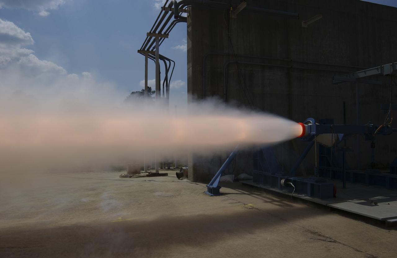
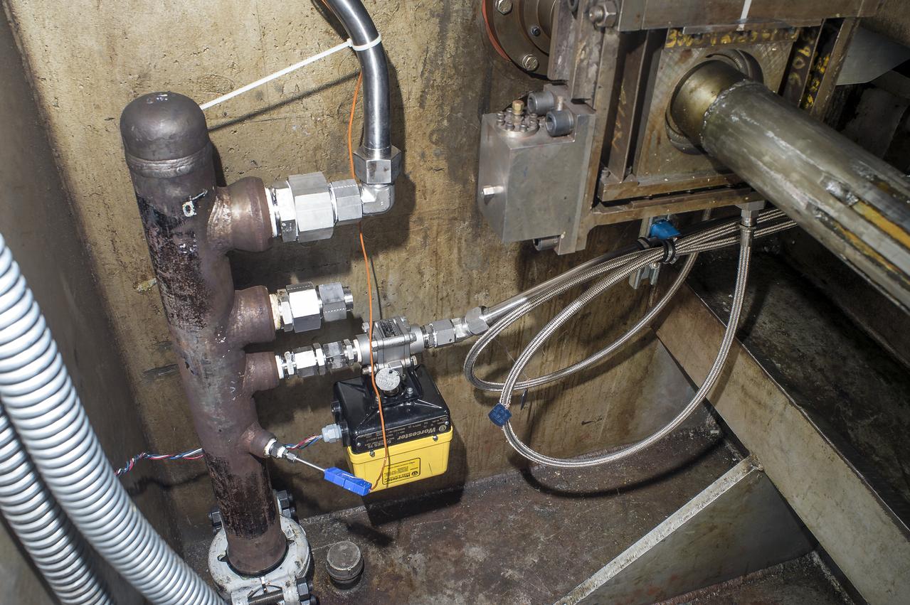
This photograph depicts a hot fire test of the Shuttle Booster Separation Motor (BSM) at the Marshall Space Flight Center (MSFC) test stand 116. The objective of the test was to test the aft heat seal in flight configuration. The function of the motor is to separate the Shuttle vehicle from the boosters that carry it into space.
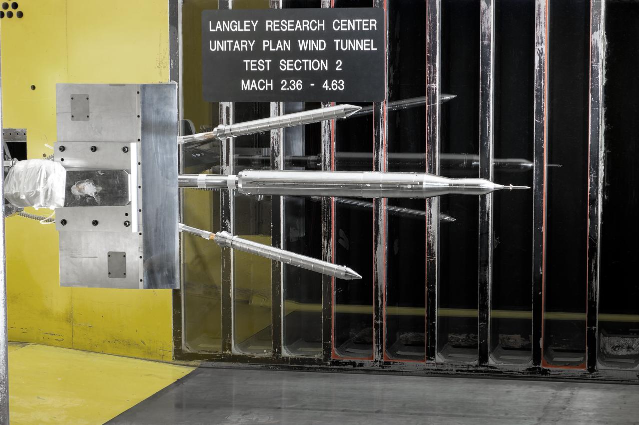
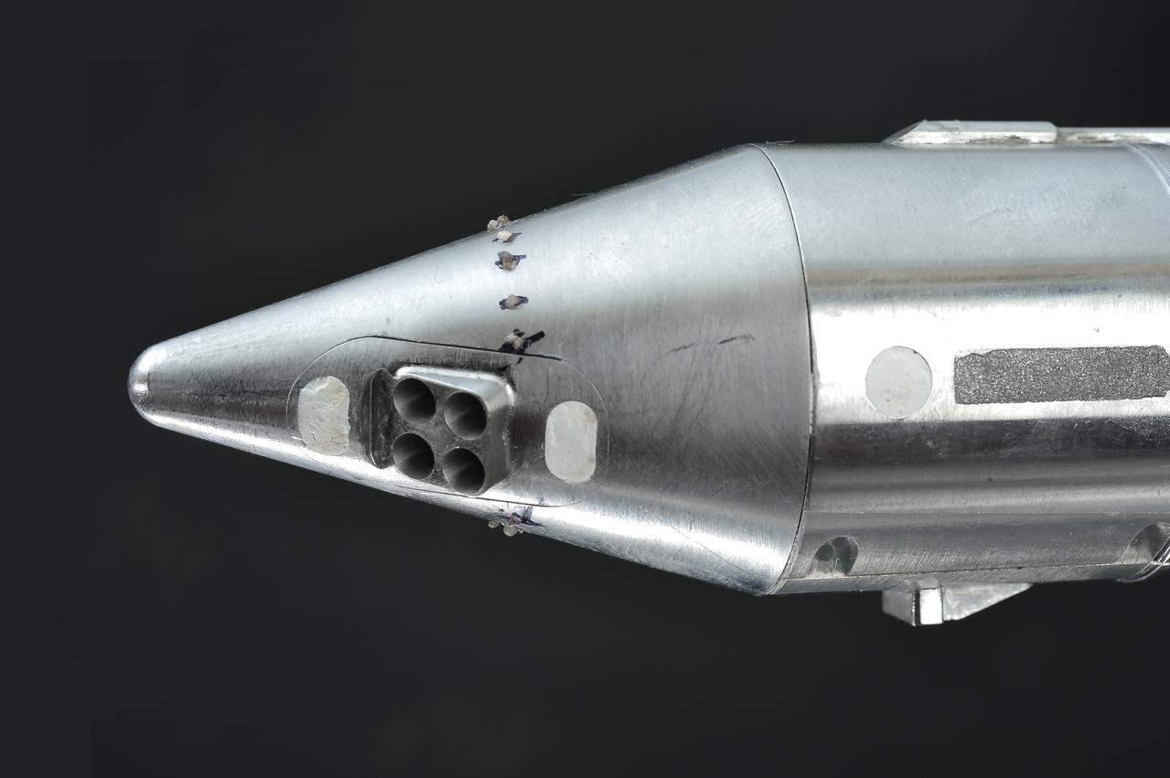
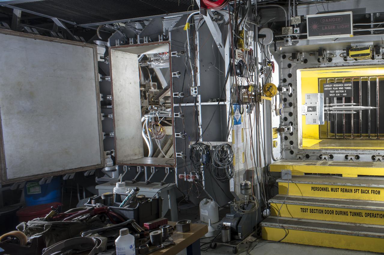
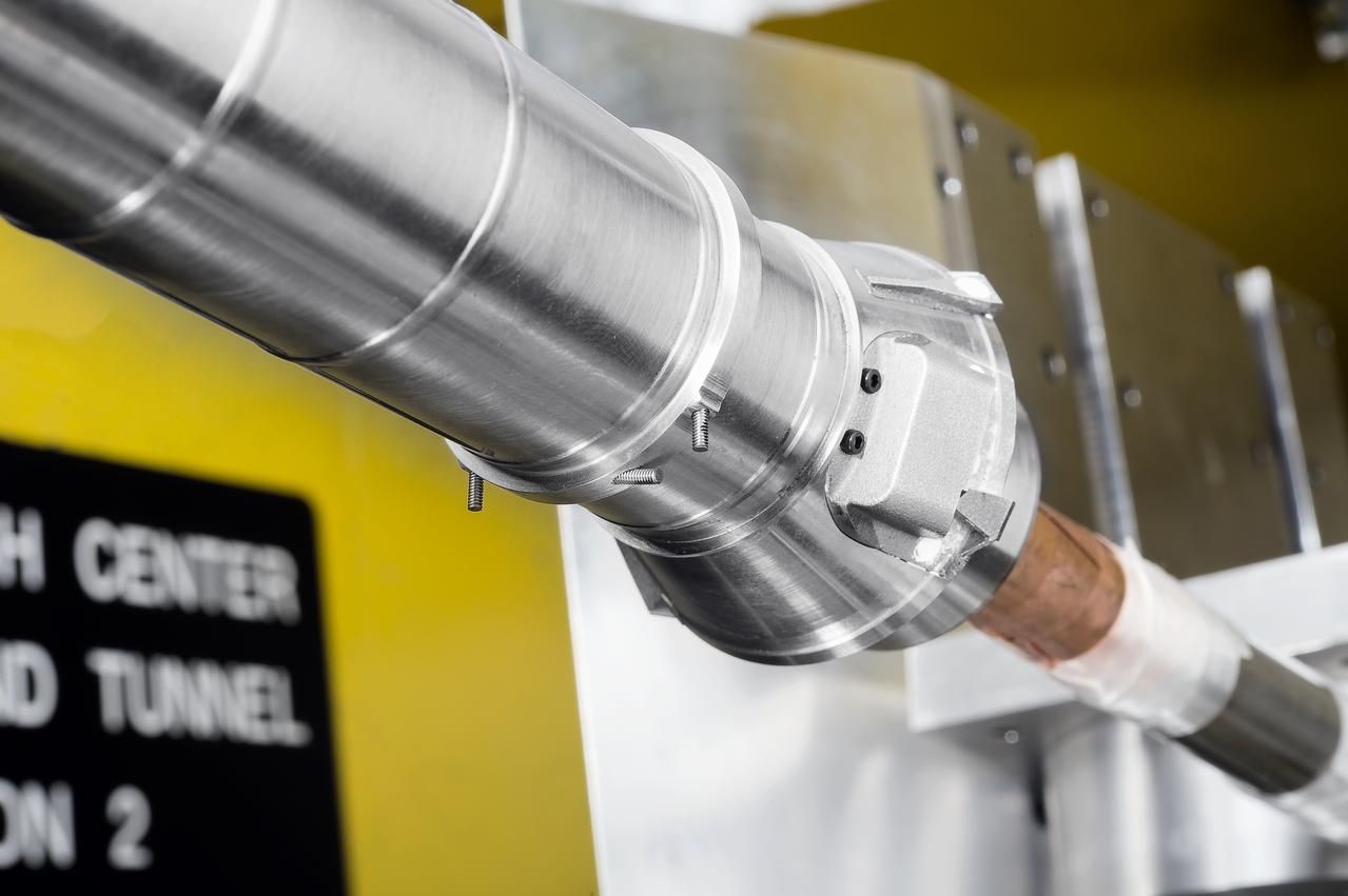
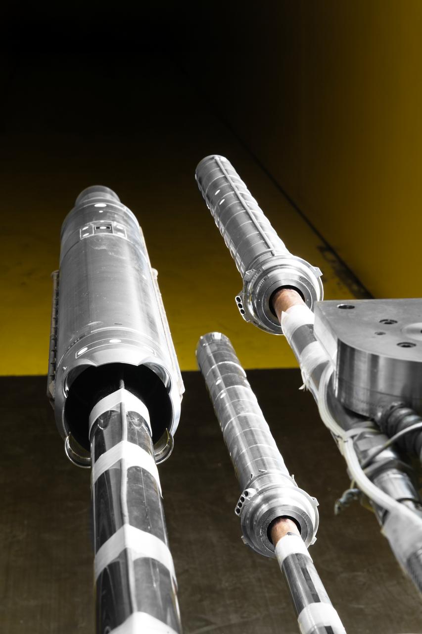
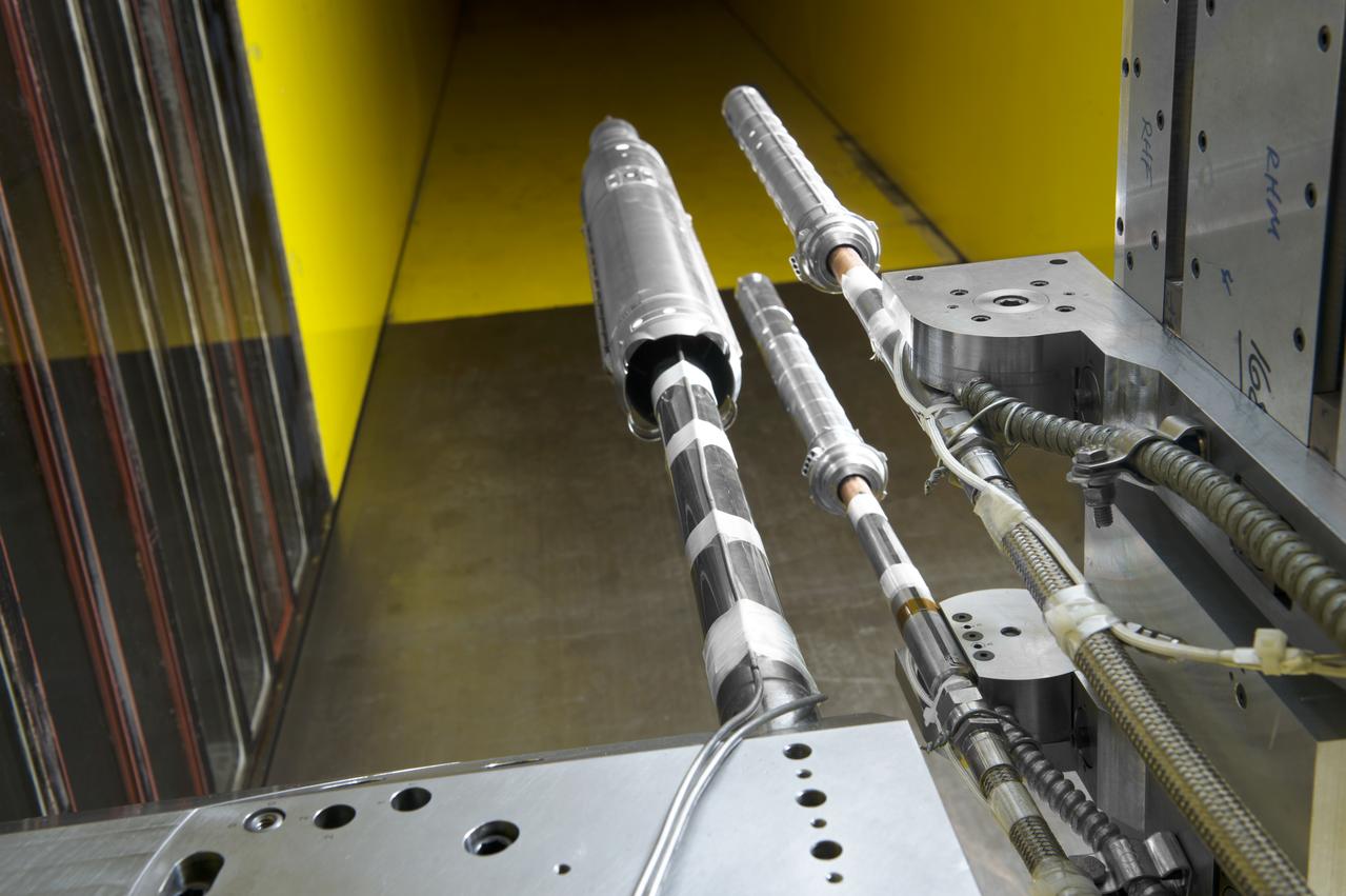
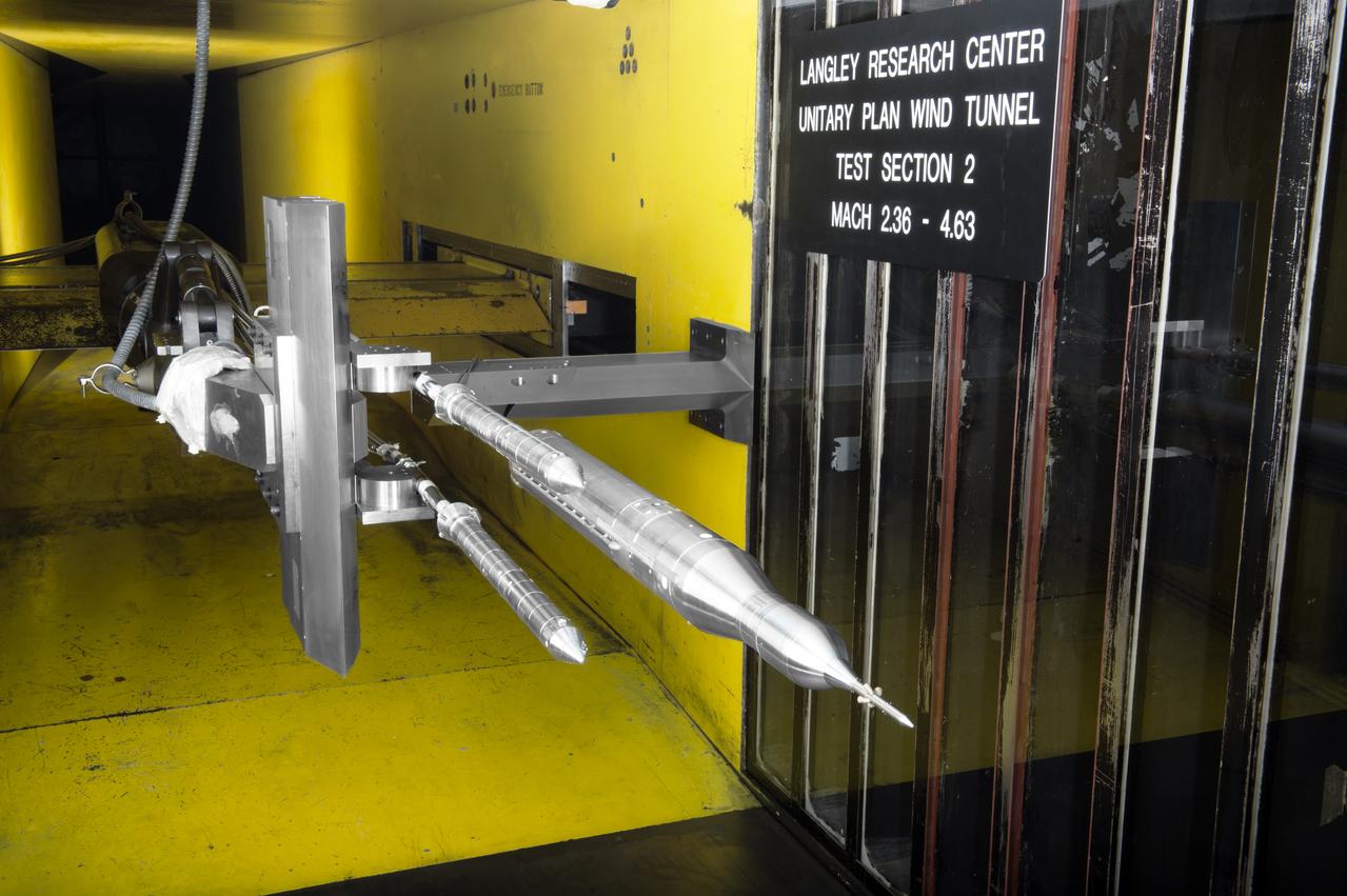
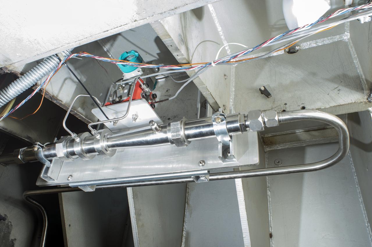
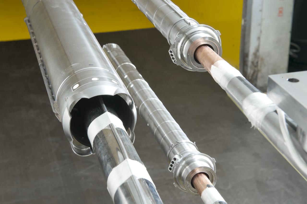
Stage Separation Test of the Space Launch System(SLS) in the Langley Unitary Plan Wind Tunnel (UPWT). The model used High Pressure air blown through the solid rocket boosters. (SRB) to simulate the booster separation motors (BSM) firing.
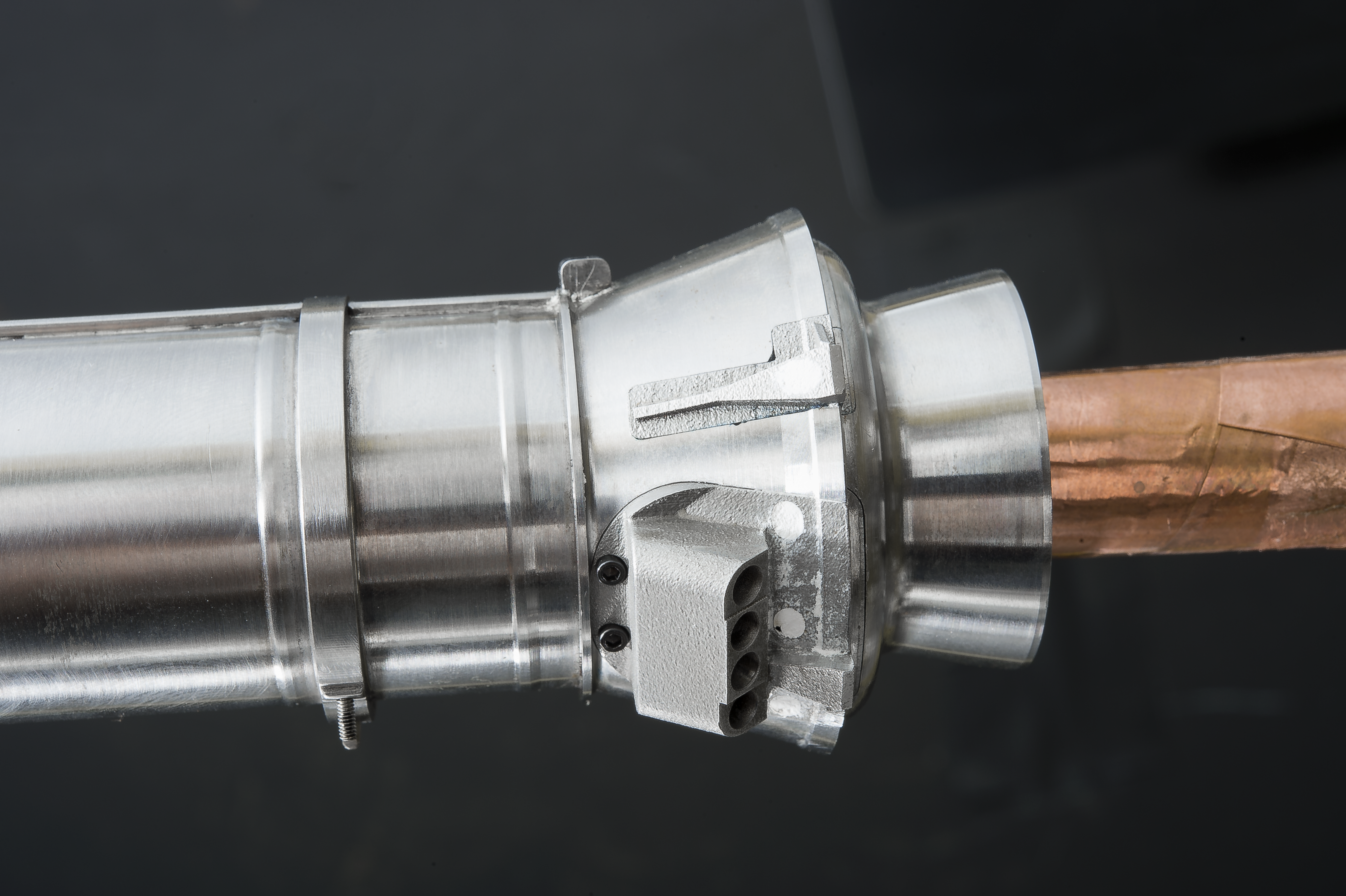
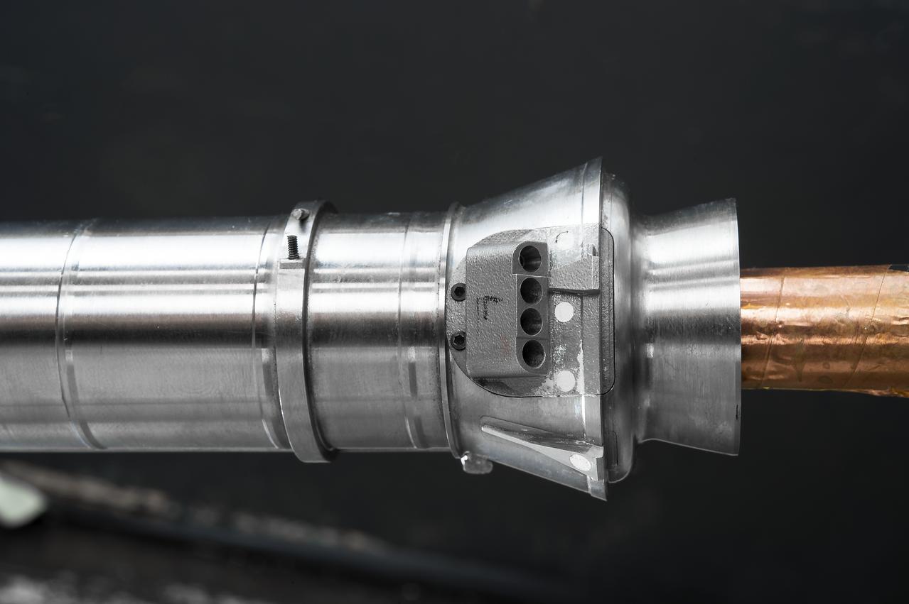
Stage Separation Test of the Space Launch System(SLS) in the Langley Unitary Plan Wind Tunnel (UPWT). The model used High Pressure air blown through the solid rocket boosters. (SRB) to simulate the booster separation motors (BSM) firing.
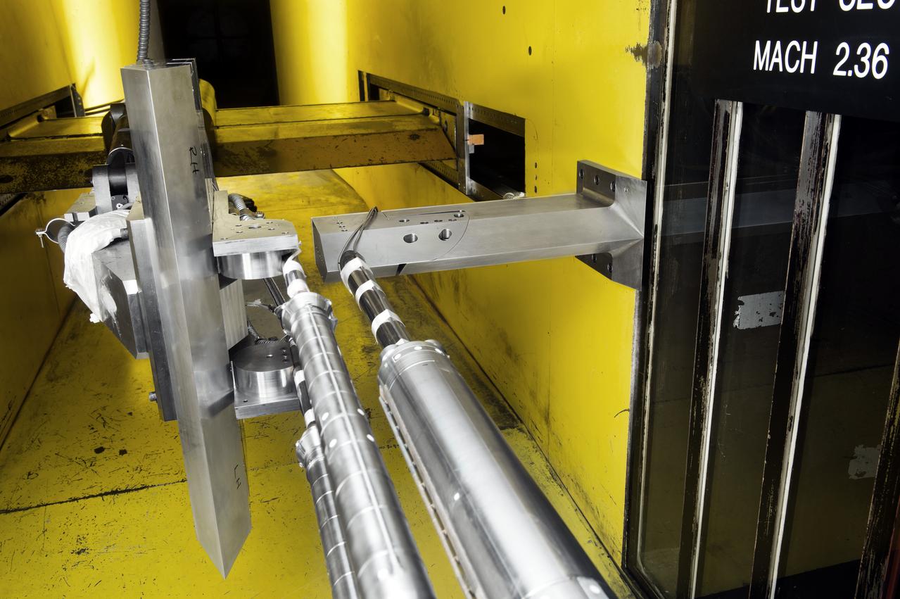
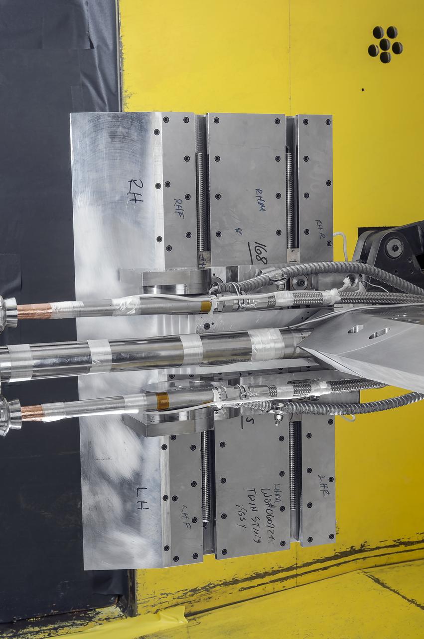
Stage Separation Test of the Space Launch System(SLS) in the Langley Unitary Plan Wind Tunnel (UPWT). The model used High Pressure air blown through the solid rocket boosters. (SRB) to simulate the booster separation motors (BSM) firing.
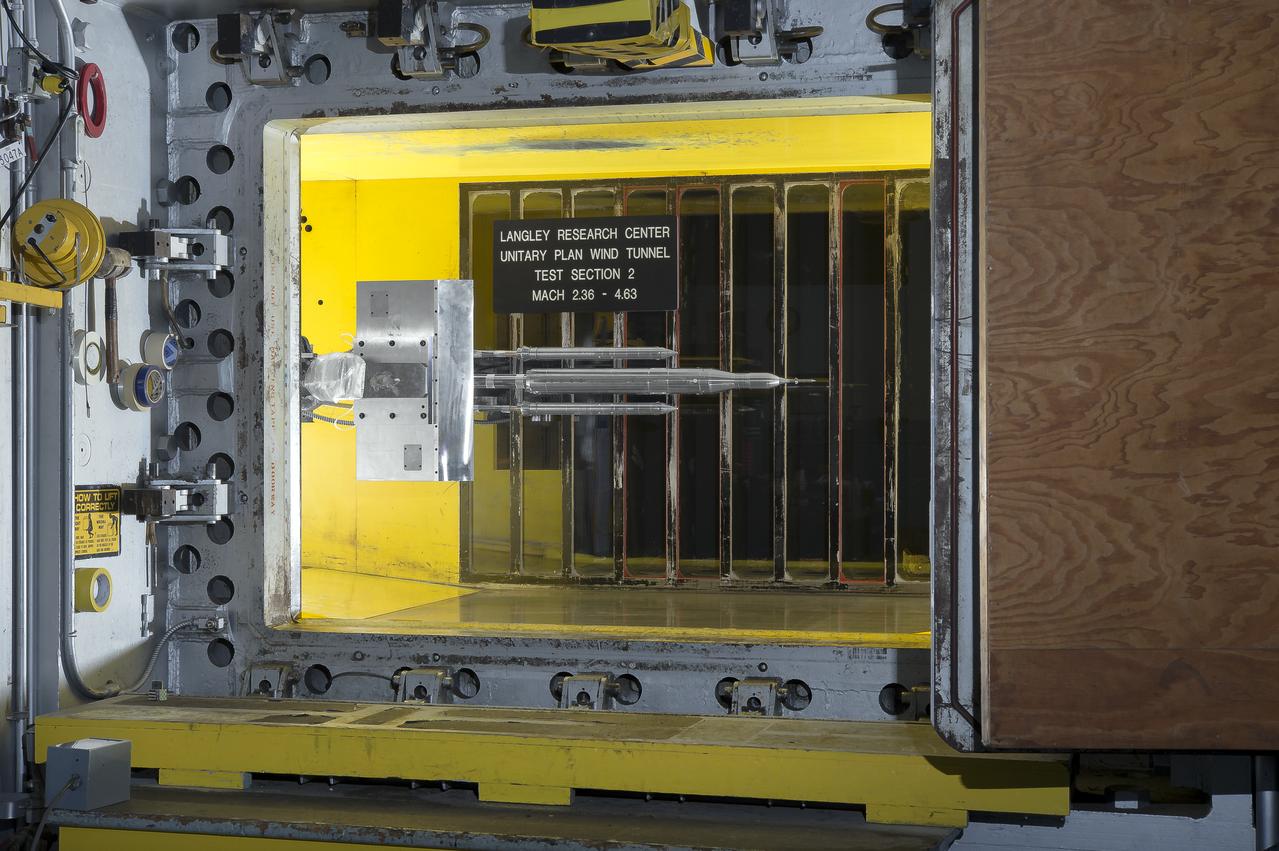
Stage Separation Test of the Space Launch System(SLS) in the Langley Unitary Plan Wind Tunnel (UPWT). The model used High Pressure air blown through the solid rocket boosters. (SRB) to simulate the booster separation motors (BSM) firing.
Stage Separation Test of the Space Launch System(SLS) in the Langley Unitary Plan Wind Tunnel (UPWT). The model used High Pressure air blown through the solid rocket boosters. (SRB) to simulate the booster separation motors (BSM) firing.
Stage Separation Test of the Space Launch System(SLS) in the Langley Unitary Plan Wind Tunnel (UPWT). The model used High Pressure air blown through the solid rocket boosters. (SRB) to simulate the booster separation motors (BSM) firing.
Stage Separation Test of the Space Launch System(SLS) in the Langley Unitary Plan Wind Tunnel (UPWT). The model used High Pressure air blown through the solid rocket boosters. (SRB) to simulate the booster separation motors (BSM) firing.
Stage Separation Test of the Space Launch System(SLS) in the Langley Unitary Plan Wind Tunnel (UPWT). The model used High Pressure air blown through the solid rocket boosters. (SRB) to simulate the booster separation motors (BSM) firing.
Stage Separation Test of the Space Launch System(SLS) in the Langley Unitary Plan Wind Tunnel (UPWT). The model used High Pressure air blown through the solid rocket boosters. (SRB) to simulate the booster separation motors (BSM) firing.

Stage Separation Test of the Space Launch System(SLS) in the Langley Unitary Plan Wind Tunnel (UPWT). The model used High Pressure air blown through the solid rocket boosters. (SRB) to simulate the booster separation motors (BSM) firing.
Stage Separation Test of the Space Launch System(SLS) in the Langley Unitary Plan Wind Tunnel (UPWT). The model used High Pressure air blown through the solid rocket boosters. (SRB) to simulate the booster separation motors (BSM) firing.
Stage Separation Test of the Space Launch System(SLS) in the Langley Unitary Plan Wind Tunnel (UPWT). The model used High Pressure air blown through the solid rocket boosters. (SRB) to simulate the booster separation motors (BSM) firing.
Stage Separation Test of the Space Launch System(SLS) in the Langley Unitary Plan Wind Tunnel (UPWT). The model used High Pressure air blown through the solid rocket boosters. (SRB) to simulate the booster separation motors (BSM) firing.

Stage Separation Test of the Space Launch System(SLS) in the Langley Unitary Plan Wind Tunnel (UPWT). The model used High Pressure air blown through the solid rocket boosters. (SRB) to simulate the booster separation motors (BSM) firing.
Stage Separation Test of the Space Launch System(SLS) in the Langley Unitary Plan Wind Tunnel (UPWT). The model used High Pressure air blown through the solid rocket boosters. (SRB) to simulate the booster separation motors (BSM) firing.
Stage Separation Test of the Space Launch System(SLS) in the Langley Unitary Plan Wind Tunnel (UPWT). The model used High Pressure air blown through the solid rocket boosters. (SRB) to simulate the booster separation motors (BSM) firing.
Stage Separation Test of the Space Launch System(SLS) in the Langley Unitary Plan Wind Tunnel (UPWT). The model used High Pressure air blown through the solid rocket boosters. (SRB) to simulate the booster separation motors (BSM) firing.
Stage Separation Test of the Space Launch System(SLS) in the Langley Unitary Plan Wind Tunnel (UPWT). The model used High Pressure air blown through the solid rocket boosters. (SRB) to simulate the booster separation motors (BSM) firing.
Stage Separation Test of the Space Launch System(SLS) in the Langley Unitary Plan Wind Tunnel (UPWT). The model used High Pressure air blown through the solid rocket boosters. (SRB) to simulate the booster separation motors (BSM) firing.
Stage Separation Test of the Space Launch System(SLS) in the Langley Unitary Plan Wind Tunnel (UPWT). The model used High Pressure air blown through the solid rocket boosters. (SRB) to simulate the booster separation motors (BSM) firing.
Stage Separation Test of the Space Launch System(SLS) in the Langley Unitary Plan Wind Tunnel (UPWT). The model used High Pressure air blown through the solid rocket boosters. (SRB) to simulate the booster separation motors (BSM) firing.
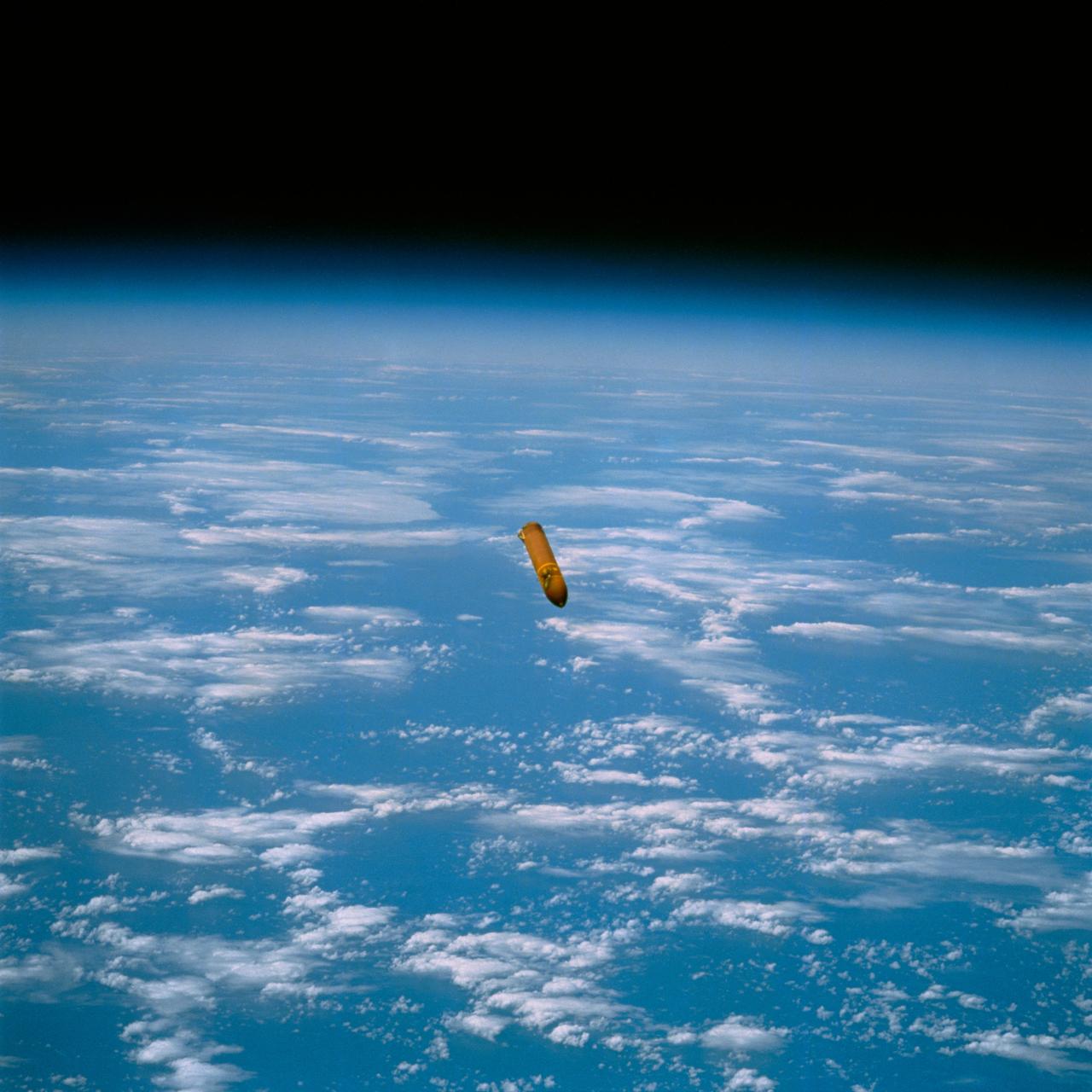
STS029-72-059 (13 March 1989) --- This 70mm photograph, taken by Astronaut James P. Bagian 16 minutes and 7 seconds after liftoff of Discovery, shows the external fuel tank (ET) against the background of Earth. The tank is falling away from the orbiter following ET separation. The left side shows the burn scar above the solid rocket booster (SRB) forward attach point. The burn is caused by the forward SRB separation motors firing during SRB separation. Post 51-L analysis of the thermal and pressure effects of the separation motor exhaust plume indicate that the scarring is not a safety hazard. However, photographs such as this one were requested for additional missions in order to document the phenomenon and corroborate this conclusion. The photo was made at 15:13:07 GMT, March 13, 1989. It was among the visuals used by the crew at its Mar. 28, 1989 post-flight press conference.
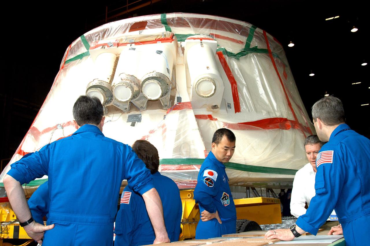
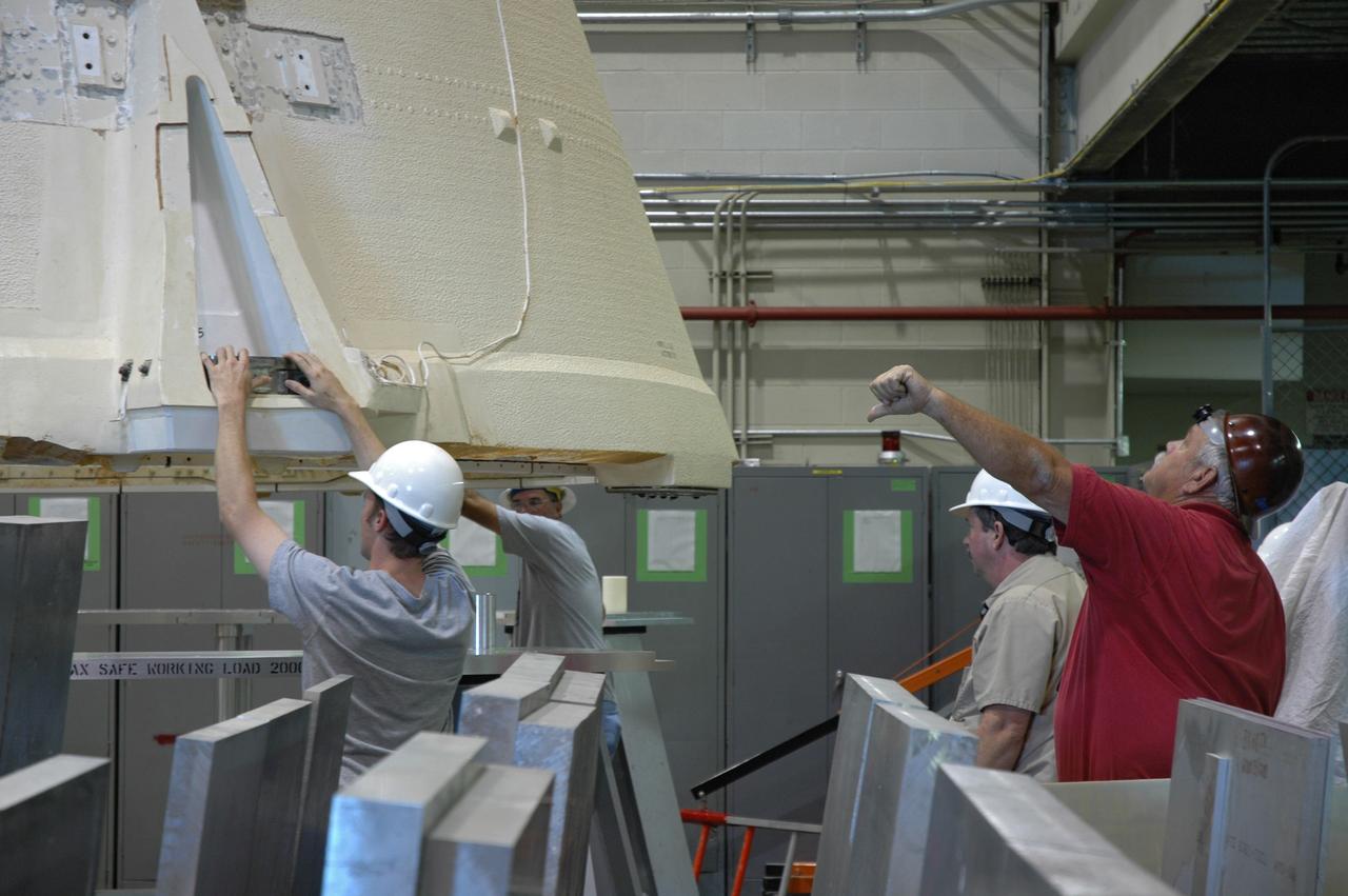
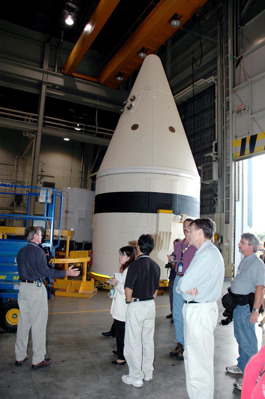
KENNEDY SPACE CENTER, FLA. - At the SRB Assembly and Refurbishment Facility, STS-114 crew members look at the booster separation motors (BSM) on a solid rocket booster aft skirt. The BSMs have had booster trowlable ablative removed by liquid nitrogen cutting. The STS-114 crew is at KSC for familiarization with Shuttle and mission equipment. The mission is Logistics Flight 1, which is scheduled to deliver supplies and equipment, plus the external stowage platform, to the International Space Station.
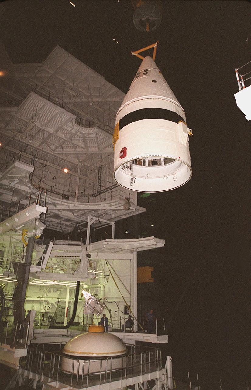
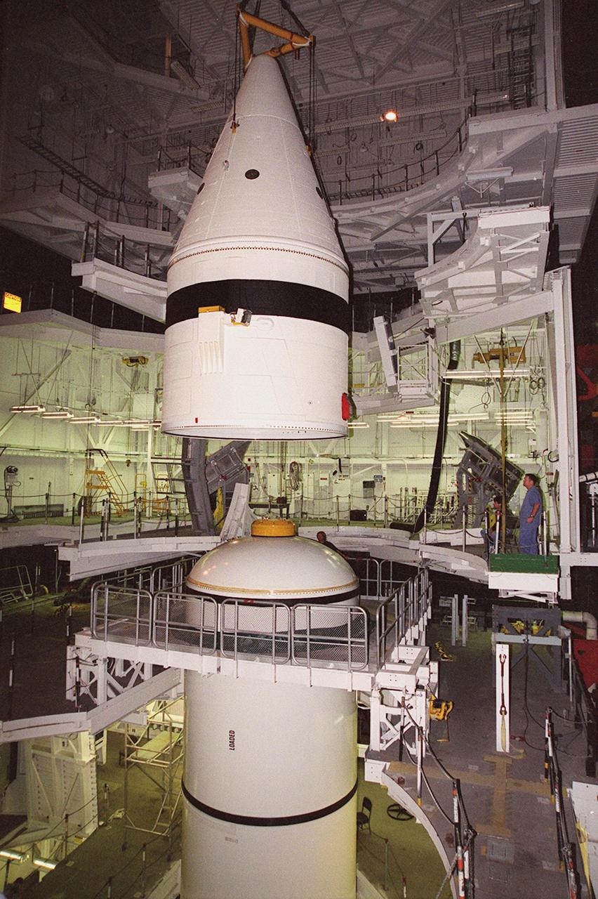
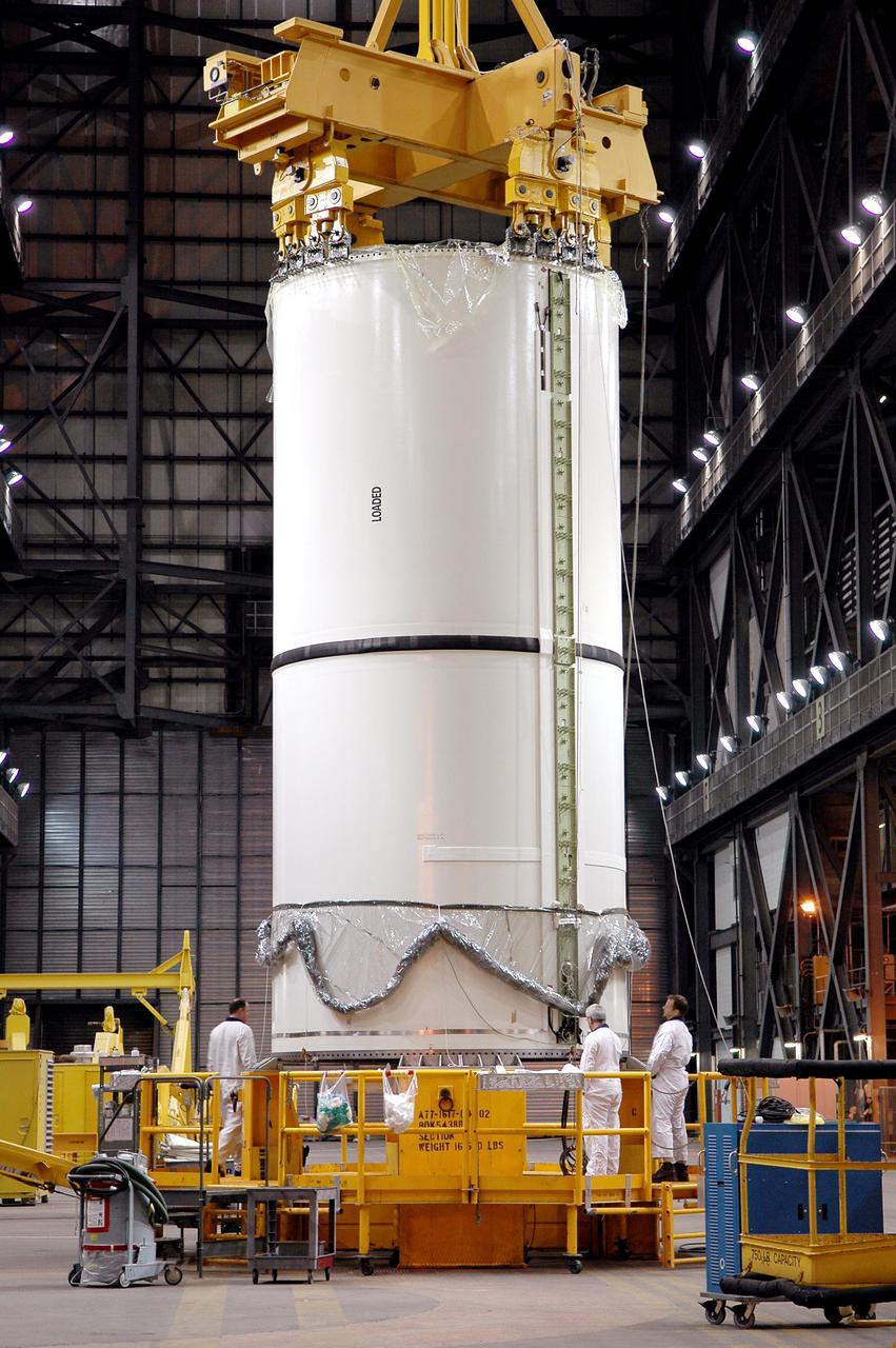
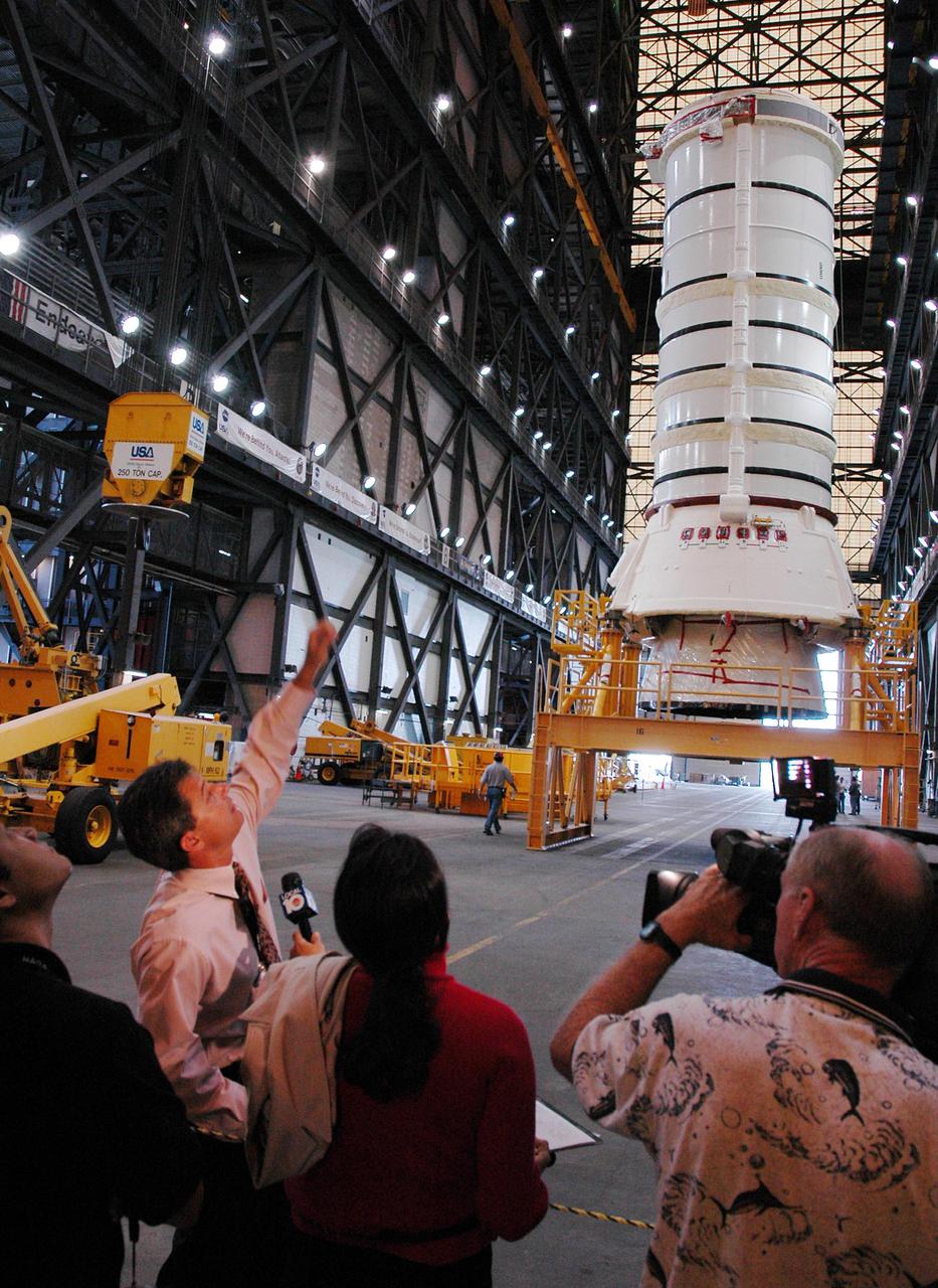
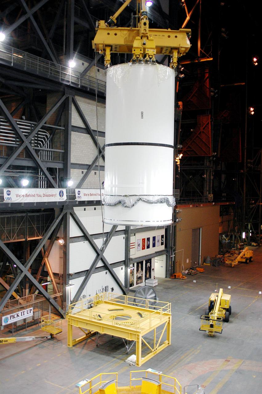
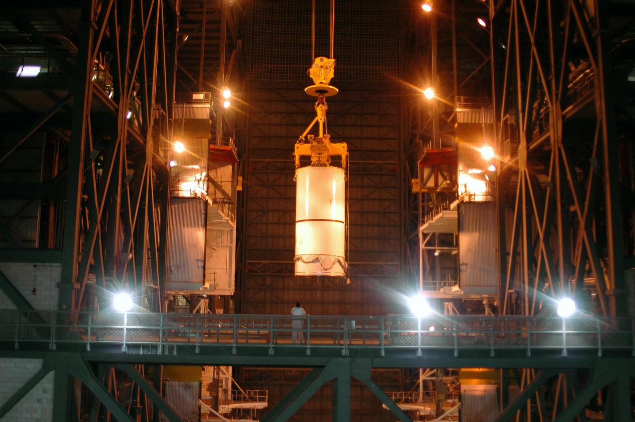
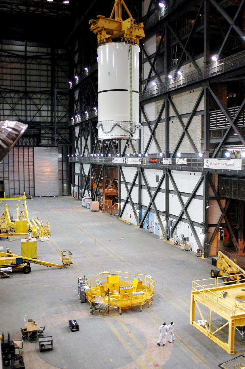
Inside the Vehicle Assembly Building, an overhead crane lifts the forward section of a solid rocket booster (SRB) to mate it with the components seen at lower left in the photo. The forward section of each booster, from nose cap to forward skirt contains avionics, a sequencer, forward separation motors, a nose cone separation system, drogue and main parachutes, a recovery beacon, a recovery light, a parachute camera on selected flights and a range safety system. Each SRB weighs approximately 1.3 million pounds at launch. The SRB is part of the stack for Space Shuttle Discovery and the STS-92 mission, scheduled for launch Oct. 5, from Launch Pad 39A, on the fifth flight to the International Space Station

Inside the Vehicle Assembly Building, an overhead crane lifts the forward section of a solid rocket booster (SRB) to mate it with the components seen at lower left in the photo. The forward section of each booster, from nose cap to forward skirt contains avionics, a sequencer, forward separation motors, a nose cone separation system, drogue and main parachutes, a recovery beacon, a recovery light, a parachute camera on selected flights and a range safety system. Each SRB weighs approximately 1.3 million pounds at launch. The SRB is part of the stack for Space Shuttle Discovery and the STS-92 mission, scheduled for launch Oct. 5, from Launch Pad 39A, on the fifth flight to the International Space Station
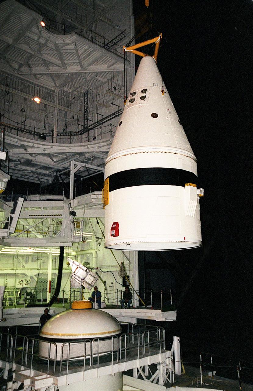
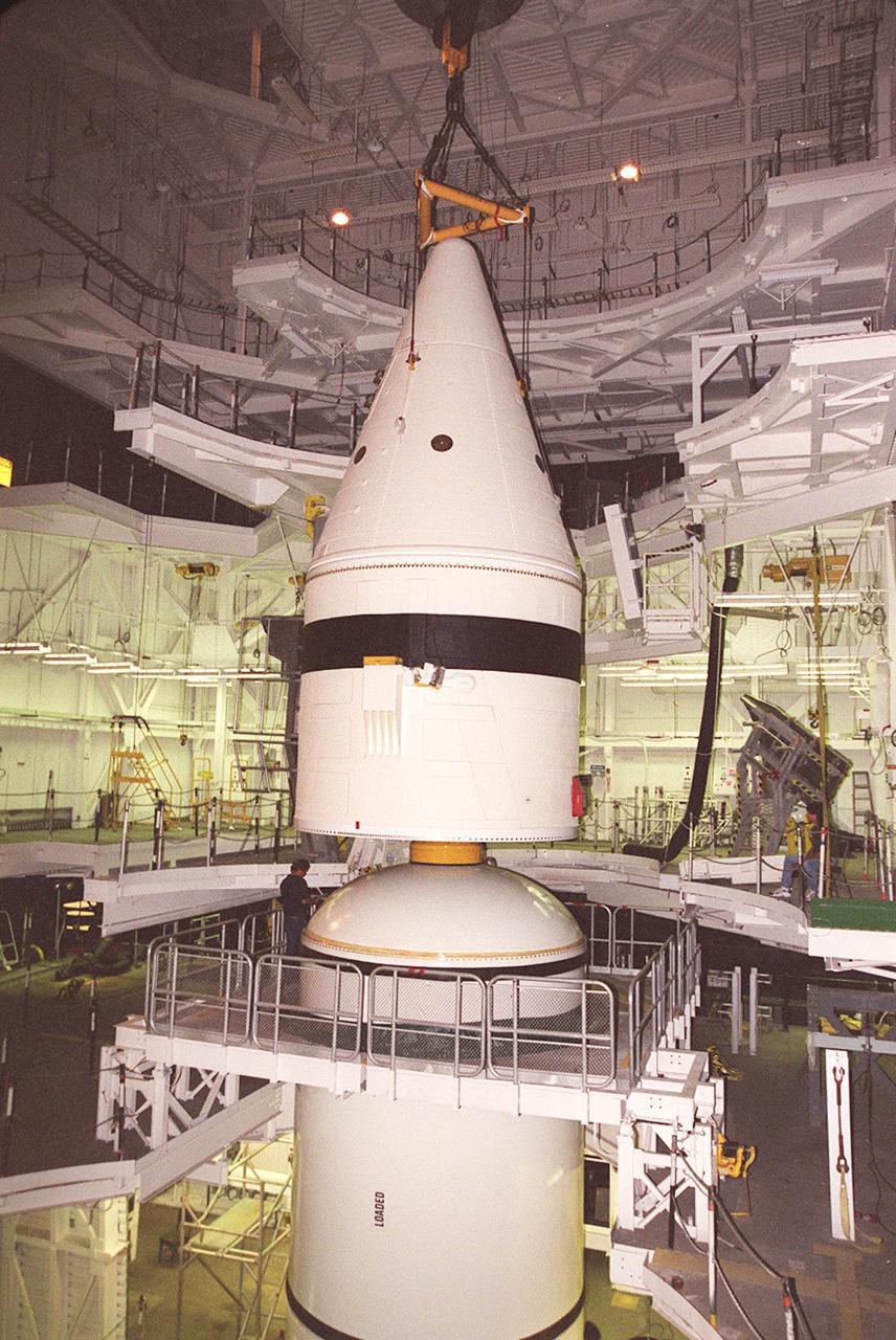
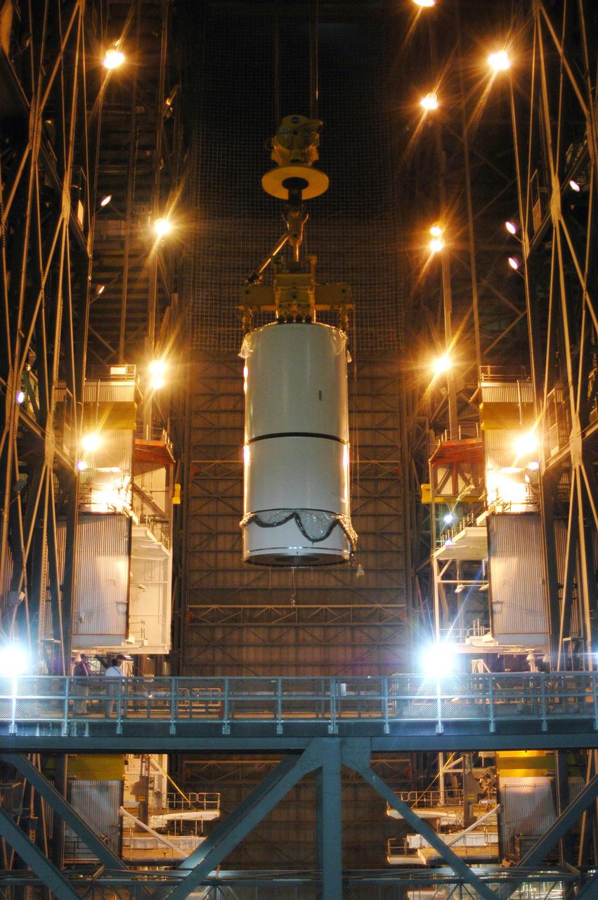
Inside the Vehicle Assembly Building, an overhead crane moves the forward section of a solid rocket booster (SRB) toward the previously stacked elements at lower left in the photo. The forward section of each booster, from nose cap to forward skirt contains avionics, a sequencer, forward separation motors, a nose cone separation system, drogue and main parachutes, a recovery beacon, a recovery light, a parachute camera on selected flights and a range safety system. Each SRB weighs approximately 1.3 million pounds at launch. The SRB is part of the stack for Space Shuttle Discovery and the STS-92 mission, scheduled for launch Oct. 5, from Launch Pad 39A, on the fifth flight to the International Space Station

Inside the Vehicle Assembly Building, an overhead crane moves the forward section of a solid rocket booster (SRB) toward the previously stacked elements at lower left in the photo. The forward section of each booster, from nose cap to forward skirt contains avionics, a sequencer, forward separation motors, a nose cone separation system, drogue and main parachutes, a recovery beacon, a recovery light, a parachute camera on selected flights and a range safety system. Each SRB weighs approximately 1.3 million pounds at launch. The SRB is part of the stack for Space Shuttle Discovery and the STS-92 mission, scheduled for launch Oct. 5, from Launch Pad 39A, on the fifth flight to the International Space Station
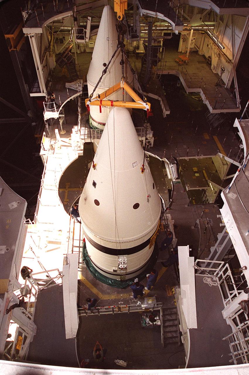
Inside the Vehicle Assembly Building, an overhead crane centers the forward section of a solid rocket booster (SRB) above the rest of the stack it will be mated to. The forward section of each booster, from nose cap to forward skirt contains avionics, a sequencer, forward separation motors, a nose cone separation system, drogue and main parachutes, a recovery beacon, a recovery light, a parachute camera on selected flights and a range safety system. Each SRB weighs approximately 1.3 million pounds at launch. The SRB is part of the stack for Space Shuttle Discovery and the STS-92 mission, scheduled for launch Oct. 5, from Launch Pad 39A, on the fifth flight to the International Space Station
Inside the Vehicle Assembly Building, an overhead crane lowers the forward section of a solid rocket booster (SRB) toward the rest of the stack for mating. The forward section of each booster, from nose cap to forward skirt contains avionics, a sequencer, forward separation motors, a nose cone separation system, drogue and main parachutes, a recovery beacon, a recovery light, a parachute camera on selected flights and a range safety system. Each SRB weighs approximately 1.3 million pounds at launch. The SRB is part of the stack for Space Shuttle Discovery and the STS-92 mission, scheduled for launch Oct. 5, from Launch Pad 39A, on the fifth flight to the International Space Station

Inside the Vehicle Assembly Building, an overhead crane lowers the forward section of a solid rocket booster (SRB) toward the rest of the stack for mating. The forward section of each booster, from nose cap to forward skirt contains avionics, a sequencer, forward separation motors, a nose cone separation system, drogue and main parachutes, a recovery beacon, a recovery light, a parachute camera on selected flights and a range safety system. Each SRB weighs approximately 1.3 million pounds at launch. The SRB is part of the stack for Space Shuttle Discovery and the STS-92 mission, scheduled for launch Oct. 5, from Launch Pad 39A, on the fifth flight to the International Space Station

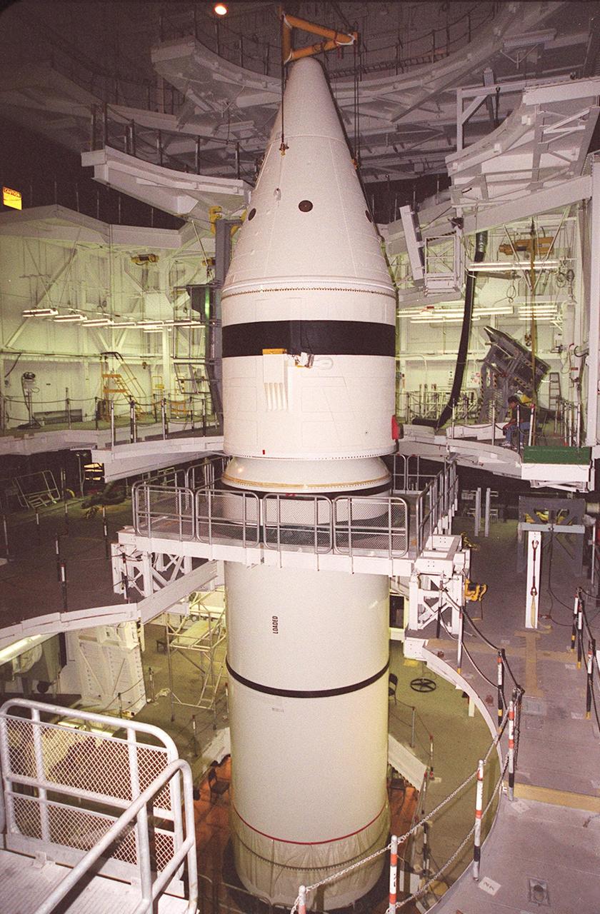
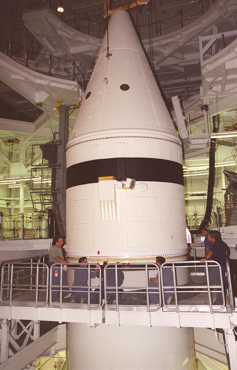
Inside the Vehicle Assembly Building, the forward section of a solid rocket booster (SRB) sits on top of the rest of the stack for mating. The forward section of each booster, from nose cap to forward skirt contains avionics, a sequencer, forward separation motors, a nose cone separation system, drogue and main parachutes, a recovery beacon, a recovery light, a parachute camera on selected flights and a range safety system. Each SRB weighs approximately 1.3 million pounds at launch. The SRB is part of the stack for Space Shuttle Discovery and the STS-92 mission, scheduled for launch Oct. 5, from Launch Pad 39A, on the fifth flight to the International Space Station
Inside the Vehicle Assembly Building, the forward section of a solid rocket booster (SRB) sits on top of the rest of the stack for mating. The forward section of each booster, from nose cap to forward skirt contains avionics, a sequencer, forward separation motors, a nose cone separation system, drogue and main parachutes, a recovery beacon, a recovery light, a parachute camera on selected flights and a range safety system. Each SRB weighs approximately 1.3 million pounds at launch. The SRB is part of the stack for Space Shuttle Discovery and the STS-92 mission, scheduled for launch Oct. 5, from Launch Pad 39A, on the fifth flight to the International Space Station

Inside the Vehicle Assembly Building, the forward section of a solid rocket booster (SRB) is lowered onto the rest of the stack for mating. The forward section of each booster, from nose cap to forward skirt contains avionics, a sequencer, forward separation motors, a nose cone separation system, drogue and main parachutes, a recovery beacon, a recovery light, a parachute camera on selected flights and a range safety system. Each SRB weighs approximately 1.3 million pounds at launch. The SRB is part of the stack for Space Shuttle Discovery and the STS-92 mission, scheduled for launch Oct. 5, from Launch Pad 39A, on the fifth flight to the International Space Station

Inside the Vehicle Assembly Building, an overhead crane centers the forward section of a solid rocket booster (SRB) above the rest of the stack it will be mated to. The forward section of each booster, from nose cap to forward skirt contains avionics, a sequencer, forward separation motors, a nose cone separation system, drogue and main parachutes, a recovery beacon, a recovery light, a parachute camera on selected flights and a range safety system. Each SRB weighs approximately 1.3 million pounds at launch. The SRB is part of the stack for Space Shuttle Discovery and the STS-92 mission, scheduled for launch Oct. 5, from Launch Pad 39A, on the fifth flight to the International Space Station
Inside the Vehicle Assembly Building, the forward section of a solid rocket booster (SRB) is lowered onto the rest of the stack for mating. The forward section of each booster, from nose cap to forward skirt contains avionics, a sequencer, forward separation motors, a nose cone separation system, drogue and main parachutes, a recovery beacon, a recovery light, a parachute camera on selected flights and a range safety system. Each SRB weighs approximately 1.3 million pounds at launch. The SRB is part of the stack for Space Shuttle Discovery and the STS-92 mission, scheduled for launch Oct. 5, from Launch Pad 39A, on the fifth flight to the International Space Station
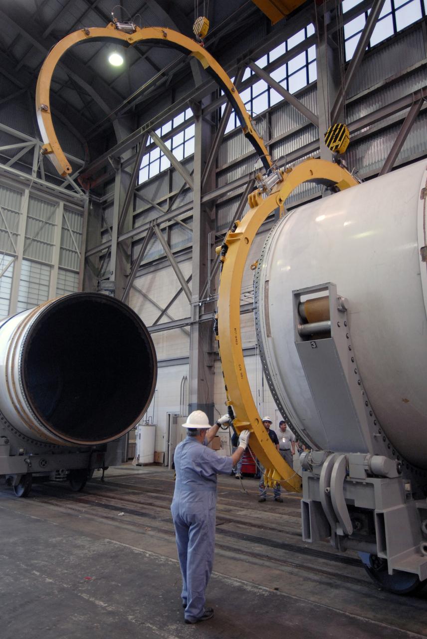
CAPE CANAVERAL, Fla. -- In Hangar AF at Cape Canaveral, Fla., workers remove the separation rings from around a segment of one of the retrieved solid rocket boosters from the STS-126 launch. The pins attaching the segments to each other are removed at the start. Each separation ring has three joints that help mold the ring around the segment and an air motor is used to rotate the rings to separate the segments. After disassembly, the segments will be sent to ATK (Alliant Techsystems) in Utah for final processing and return to Kennedy for another shuttle launch. Photo credit: NASA/Jack Pfaller
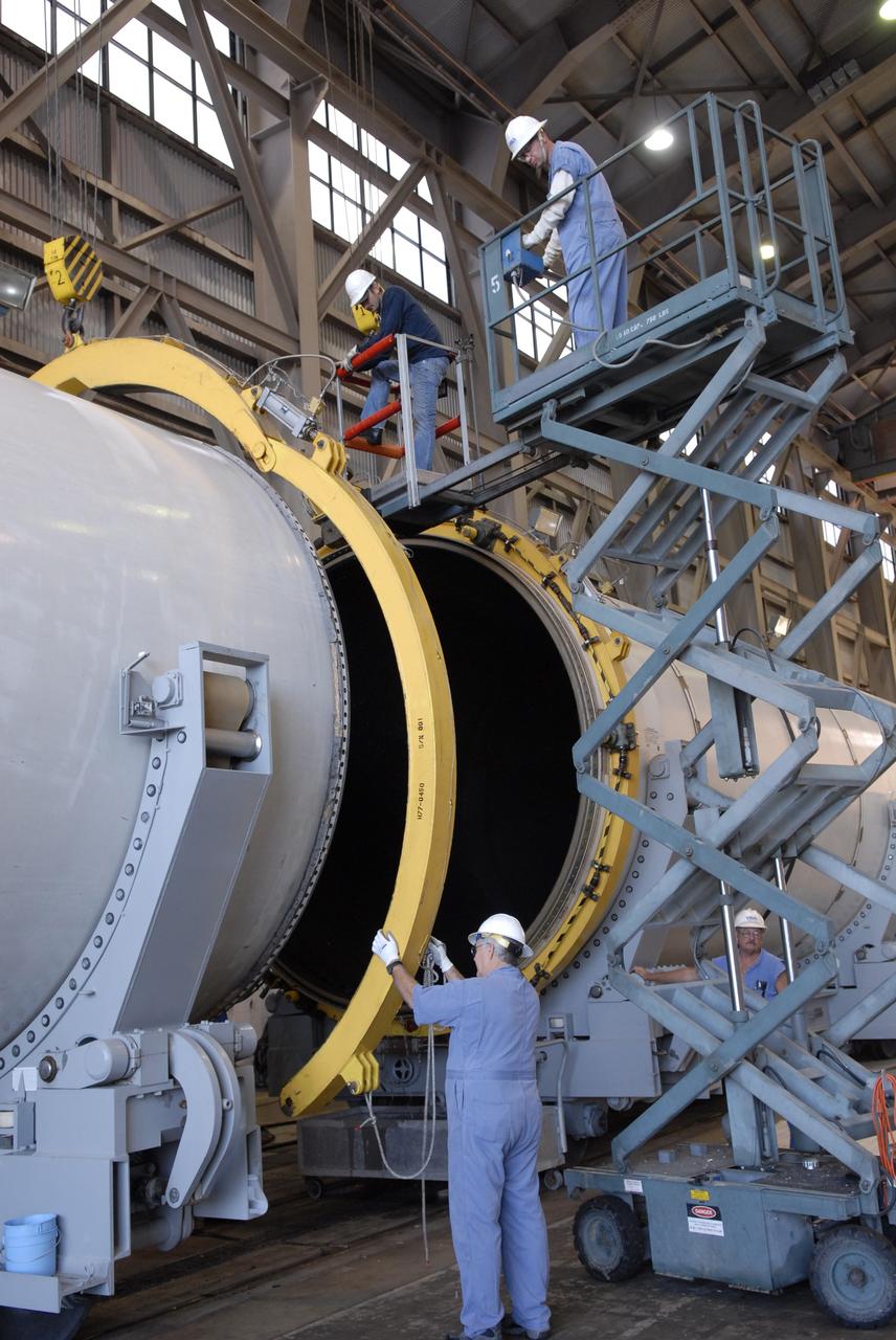
CAPE CANAVERAL, Fla. -- In Hangar AF at Cape Canaveral, Fla., workers again remove separation rings from around segments of one of the retrieved solid rocket boosters from the STS-126 launch. The pins attaching the segments to each other are removed at the start. Each separation ring has three joints that help mold the ring around the segment and an air motor is used to rotate the rings to separate the segments. After disassembly, the segments will be sent to ATK (Alliant Techsystems) in Utah for final processing and return to Kennedy for another shuttle launch. Photo credit: NASA/Jack Pfaller
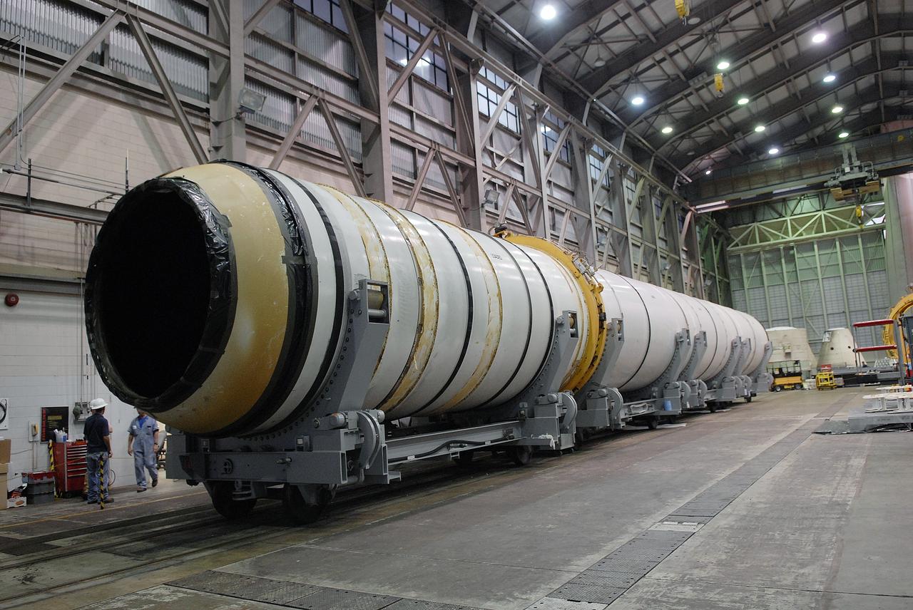
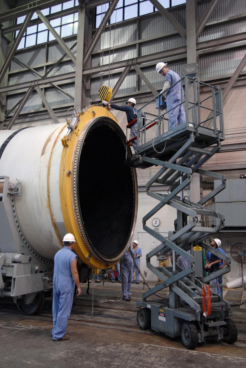
CAPE CANAVERAL, Fla. -- In Hangar AF at Cape Canaveral, Fla., one of the retrieved solid rocket boosters from the STS-126 launch is ready to be disassembled. Separation rings will be used to move the segments apart. The pins attaching the segments to each other are removed at the start. Each separation ring has three joints that help mold the ring around the seg¬ment and an air motor is used to rotate the rings to separate the segments. After disassembly, the segments will be sent to ATK (Alliant Techsystems) in Utah for final processing and return to Kennedy for another shuttle launch. Photo credit: NASA/Jack Pfaller
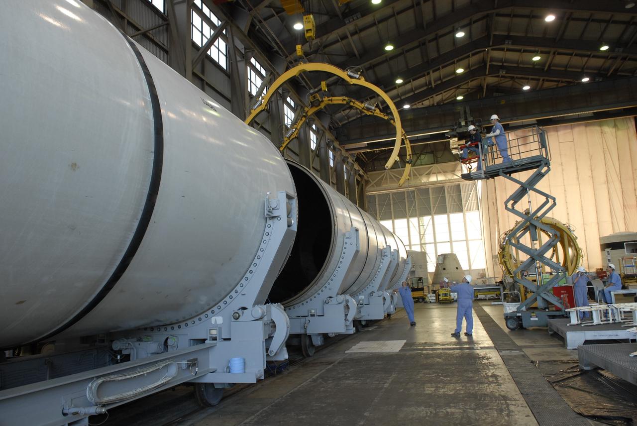
CAPE CANAVERAL, Fla. -- In Hangar AF at Cape Canaveral, Fla., separation rings are moved above two segments of one of the retrieved solid rocket boosters from the STS-126 launch. The rings will be lowered and locked around the segments. The pins attaching the segments to each other are removed at the start. Each separation ring has three joints that help mold the ring around the segment and an air motor is used to rotate the rings to separate the segments. After disassembly, the segments will be sent to ATK (Alliant Techsystems) in Utah for final processing and return to Kennedy for another shuttle launch. Photo credit: NASA/Jack Pfaller
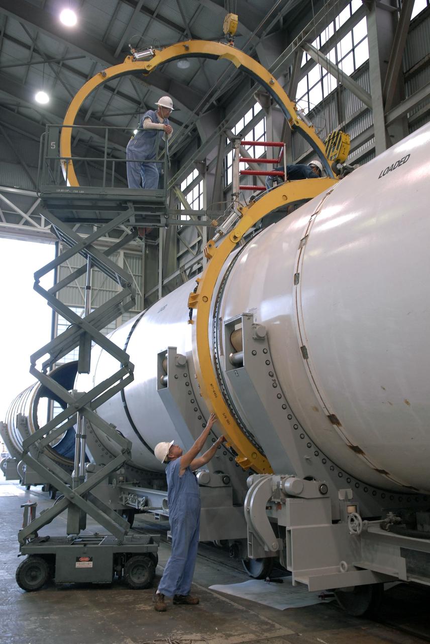
CAPE CANAVERAL, Fla. -- In Hangar AF at Cape Canaveral, Fla., workers put separation rings around segments of one of the retrieved solid rocket boosters from the STS-126 launch. The pins attaching the segments to each other are removed at the start. Each separation ring has three joints that help mold the ring around the segment and an air motor is used to rotate the rings to separate the segments. After disassembly, the segments will be sent to ATK (Alliant Techsystems) in Utah for final processing and return to Kennedy for another shuttle launch. Photo credit: NASA/Jack Pfaller
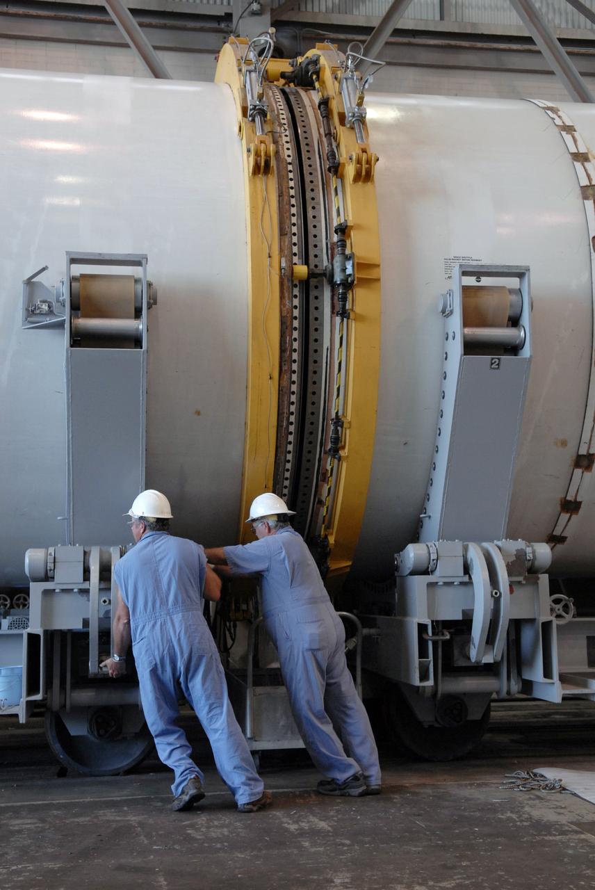
CAPE CANAVERAL, Fla. -- In Hangar AF at Cape Canaveral, Fla., with separation rings in place, workers begin to move apart segments of one of the retrieved solid rocket boosters from the STS-126 launch. The pins attaching the segments to each other are removed at the start. Each separation ring has three joints that help mold the ring around the segment and an air motor is used to rotate the rings to separate the segments. After disassembly, the segments will be sent to ATK (Alliant Techsystems) in Utah for final processing and return to Kennedy for another shuttle launch. Photo credit: NASA/Jack Pfaller
CAPE CANAVERAL, Fla. -- In Hangar AF at Cape Canaveral, Fla., workers get ready to remove one of the separation rings from around a segment of one of the retrieved solid rocket boosters from the STS-126 launch. The pins attaching the segments to each other are removed at the start. Each separation ring has three joints that help mold the ring around the segment and an air motor is used to rotate the rings to separate the segments. After disassembly, the segments will be sent to ATK (Alliant Techsystems) in Utah for final processing and return to Kennedy for another shuttle launch. Photo credit: NASA/Jack Pfaller

CAPE CANAVERAL, Fla. -- In Hangar AF at Cape Canaveral, Fla., workers separate segments of one of the retrieved solid rocket boosters from the STS-126 launch. The pins attaching the segments to each other are removed at the start. Each separation ring has three joints that help mold the ring around the segment and an air motor is used to rotate the rings to separate the segments. After disassembly, the segments will be sent to ATK (Alliant Techsystems) in Utah for final processing and return to Kennedy for another shuttle launch. Photo credit: NASA/Jack Pfaller
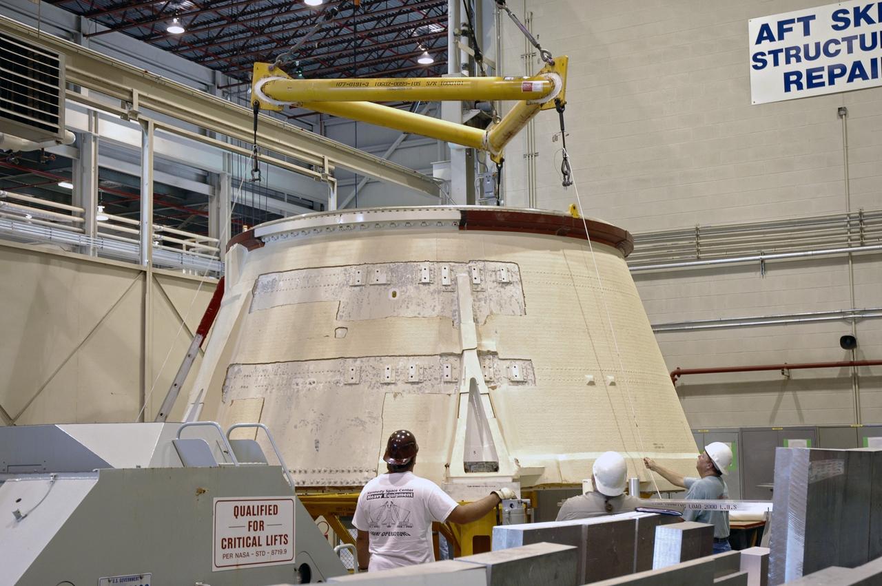
CAPE CANAVERAL, Fla. – In the Assembly and Refurbishment Facility at NASA's Kennedy Space Center, a crane is lowered over the aft skirt for the Ares 1-X rocket. The segment is being lifted into a machine shop work stand for drilling modifications. The modifications will prepare it for the installation of the auxiliary power unit controller, the reduced-rate gyro unit, the booster decelerator motors and the booster tumble motors. Ares I is an in-line, two-stage rocket that will transport the Orion crew exploration vehicle to low-Earth orbit. Ares I-X is a test rocket. The Ares I first stage will be a five-segment solid rocket booster based on the four-segment design used for the shuttle. Ares I’s fifth booster segment allows the launch vehicle to lift more weight and reach a higher altitude before the first stage separates from the upper stage, which ignites in midflight to propel the Orion spacecraft to Earth orbit. Photo credit: NASA/Jim Grossmann
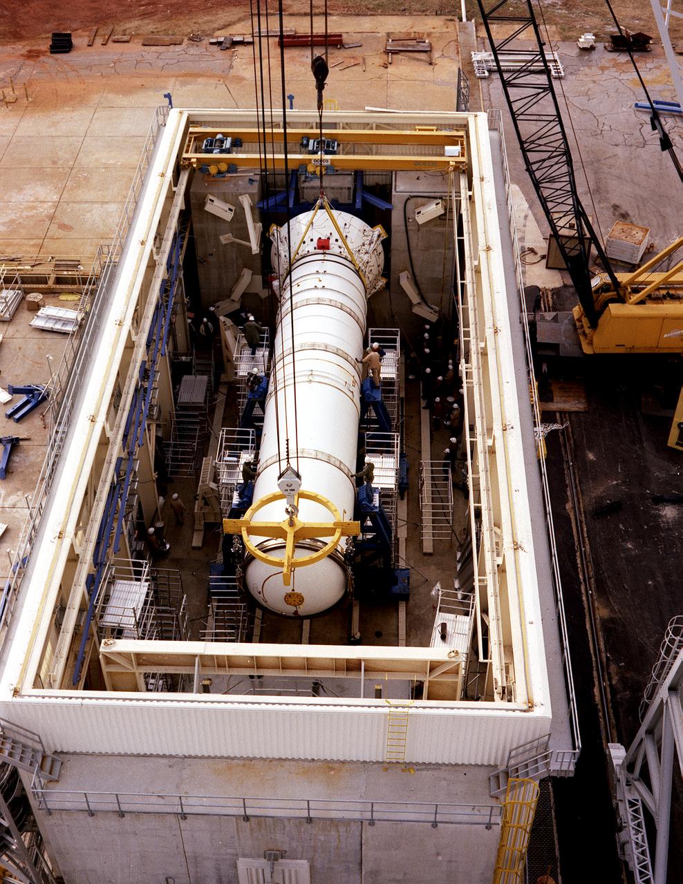
The solid rocket booster (SRB) structural test article is being installed in the Solid Rocket Booster Test Facility for the structural and load verification test at the Marshall Space Flight Center (MSFC). The Shuttle's two SRB's are the largest solids ever built and the first designed for refurbishment and reuse. Standing nearly 150-feet high, the twin boosters provide the majority of thrust for the first two minutes of flight, about 5.8 million pounds, augmenting the Shuttle's main propulsion system during liftoff. The major design drivers for the solid rocket motors (SRM's) were high thrust and reuse. The desired thrust was achieved by using state-of-the-art solid propellant and by using a long cylindrical motor with a specific core design that allows the propellant to burn in a carefully controlled marner. At burnout, the boosters separate from the external tank and drop by parachute to the ocean for recovery and subsequent refurbishment.
KENNEDY SPACE CENTER, FLA. - In the Vehicle Assembly Building (VAB), the right aft center segment of a Solid Rocket Booster (SRB) is lowered toward the aft booster for mating. The aft booster arrived in the VAB Nov. 22 for the Return to Flight mission STS-114. Two SRBs are stacked on the Mobile Launch Platform and later joined by the External Tank.. The twin 149-foot tall, 12-foot diameter SRBs provide the main propulsion system during launch. They operate parallel with the Space Shuttle main engines for the first two minutes of flight and jettison away from the orbiter with help from the Booster Separation Motors, about 26.3 nautical miles above the Earth’s surface.
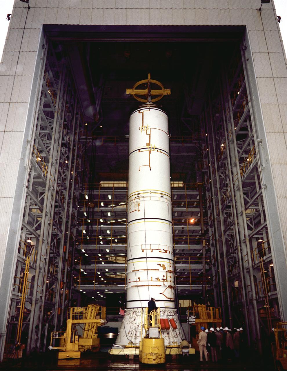
The structural test article to be used in the solid rocket booster (SRB) structural and load verification tests is being assembled in a high bay building of the Marshall Space Flight Center (MSFC). The Shuttle's two SRB's are the largest solids ever built and the first designed for refurbishment and reuse. Standing nearly 150-feet high, the twin boosters provide the majority of thrust for the first two minutes of flight, about 5.8 million pounds, augmenting the Shuttle's main propulsion system during liftoff. The major design drivers for the solid rocket motors (SRM's) were high thrust and reuse. The desired thrust was achieved by using state-of-the-art solid propellant and by using a long cylindrical motor with a specific core design that allows the propellant to burn in a carefully controlled marner. At burnout, the boosters separate from the external tank and drop by parachute to the ocean for recovery and subsequent refurbishment.
KENNEDY SPACE CENTER, FLA. - Inside the Vehicle Assembly Building (VAB), a segment of a Solid Rocket Booster (SRB) is prepared for lifting. This right aft center segment will be stacked with the aft booster that arrived in the VAB Nov. 22 for the Return to Flight mission STS-114. Two SRBs are stacked on the Mobile Launch Platform and later joined by the External Tank.. The twin 149-foot tall, 12-foot diameter SRBs provide the main propulsion system during launch. They operate parallel with the Space Shuttle main engines for the first two minutes of flight and jettison away from the orbiter with help from the Booster Separation Motors, about 26.3 nautical miles above the Earth’s surface.
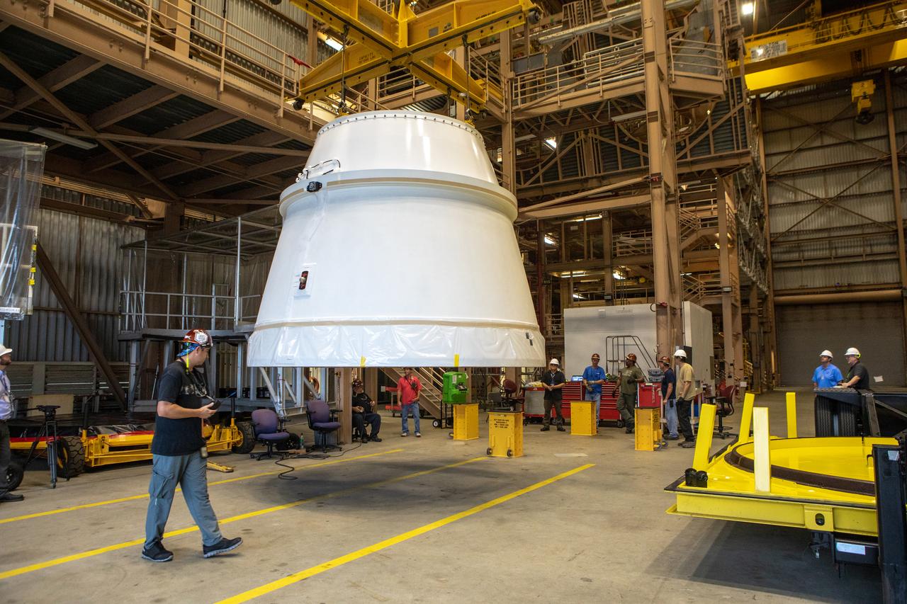
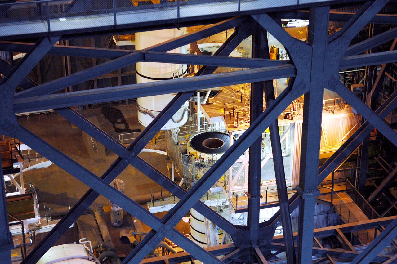
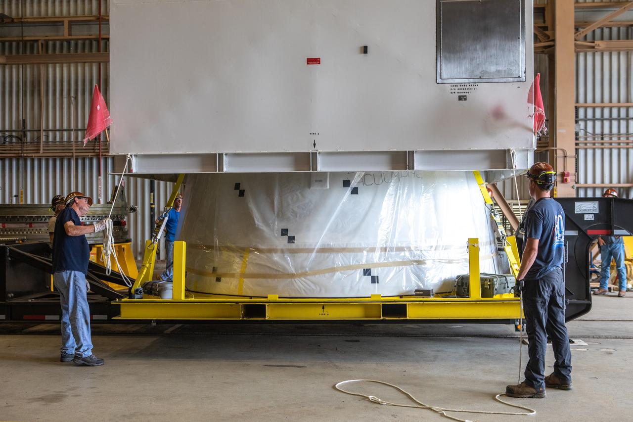
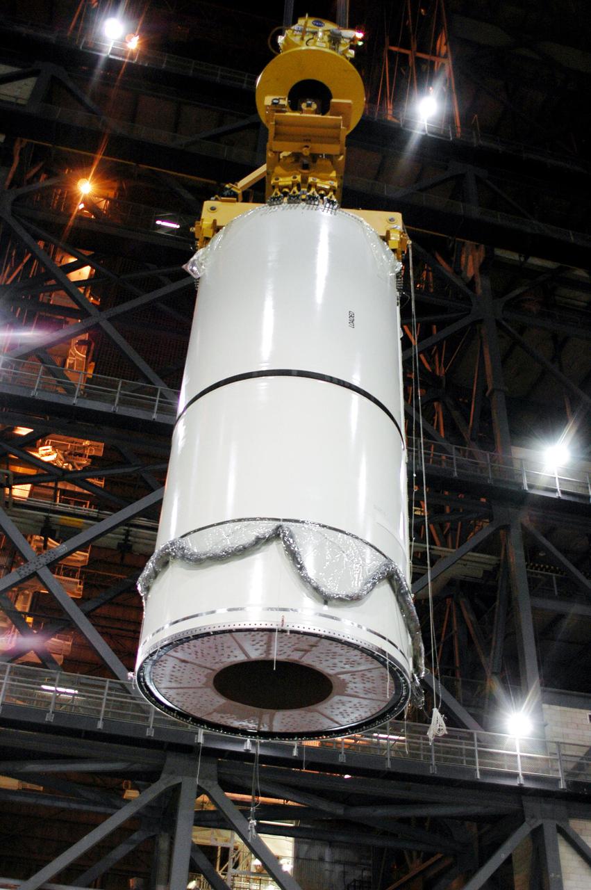
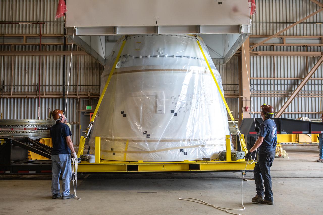
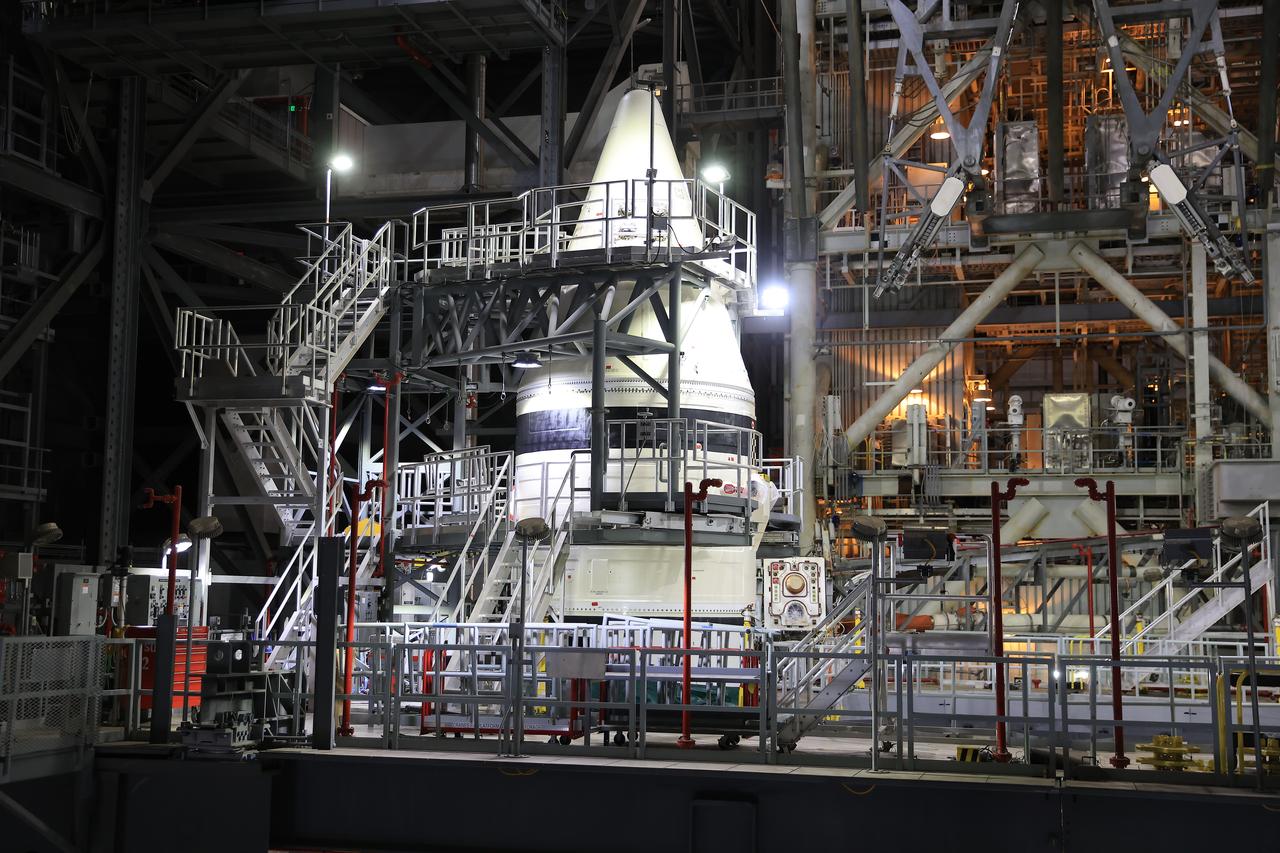
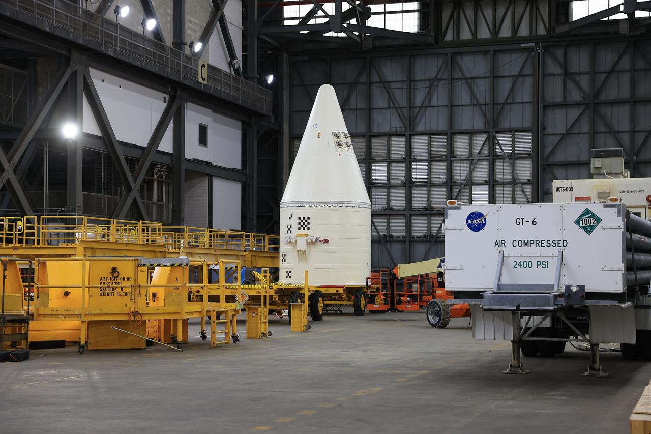
The first Northrop Grumman aft exit cone to arrive for the Space Launch System’s solid rocket boosters is moved by crane inside the Rotation, Processing and Surge Facility at NASA’s Kennedy Space Center in Florida on Nov. 4, 2019. The aft exit cone was shipped from Promontory, Utah. It will be checked out and prepared for the Artemis I uncrewed test flight. The aft exit cones sit at the bottommost part of the twin boosters. They are attached to the aft skirts, which contain the booster separation motors. The exit cones help to protect the aft skirts during launch.
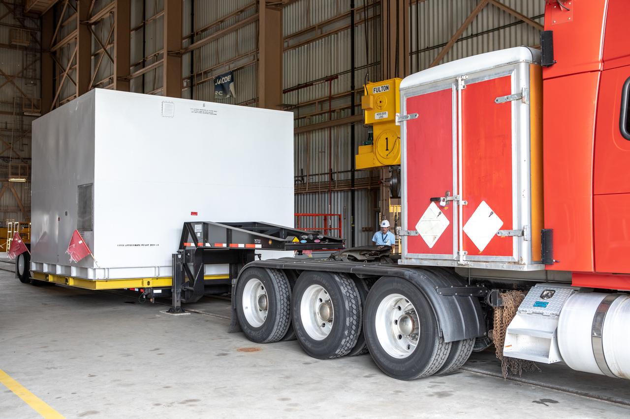
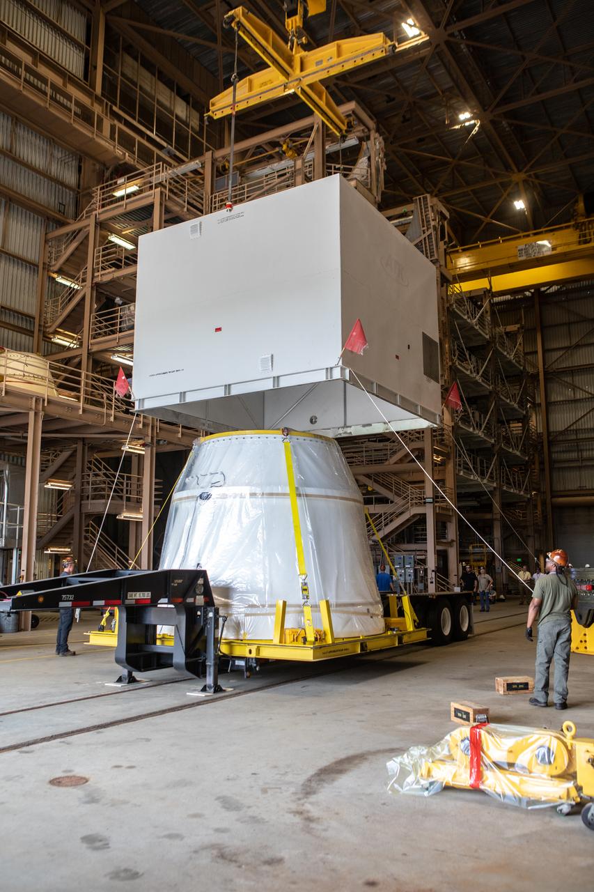
The first of two Northrop Grumman aft exit cones for the Space Launch System’s solid rocket boosters arrives by truck in its shipping container at the Rotation, Processing and Surge Facility at NASA's Kennedy Space Center in Florida on Nov. 4, 2019. The aft exit cone was shipped from Promontory, Utah. It will be checked out and prepared for the Artemis I uncrewed test flight. The aft exit cones sit at the bottommost part of the twin boosters. They are attached to the aft skirts, which contain the booster separation motors. The exit cones help to protect the aft skirts during launch.
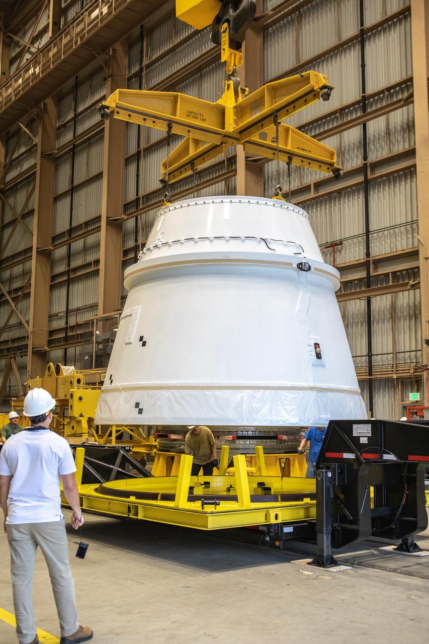
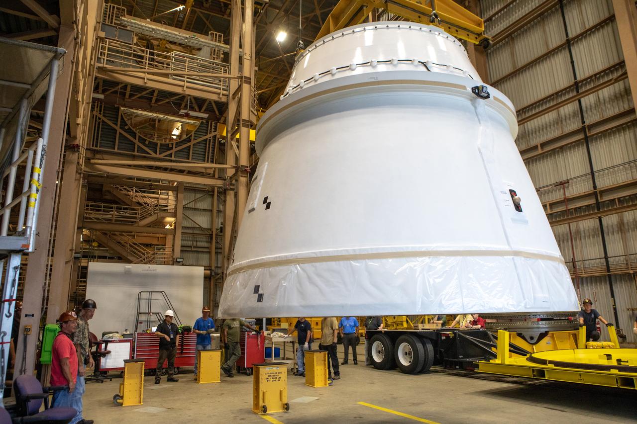
A crane is used to lift the first Northrop Grumman aft exit cone to arrive for the Space Launch System’s solid rocket boosters away from its shipping base inside the Rotation, Processing and Surge Facility at NASA’s Kennedy Space Center in Florida on Nov. 4, 2019. The aft exit cone was shipped from Promontory, Utah. It will be checked out and prepared for the Artemis I uncrewed test flight. The aft exit cones sit at the bottommost part of the twin boosters. They are attached to the aft skirts, which contain the booster separation motors. The exit cones help to protect the aft skirts during launch.
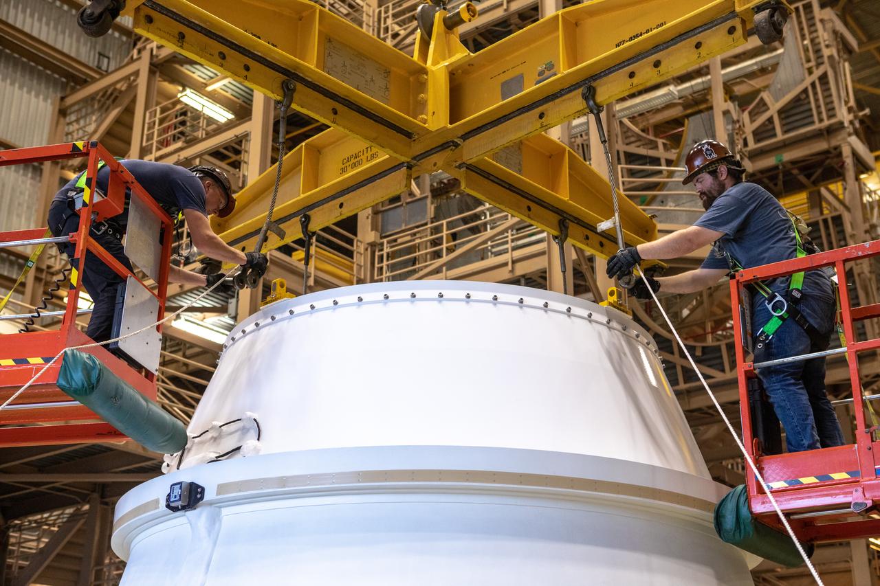
Workers attach a crane to the first Northrop Grumman aft exit cone to arrive for the Space Launch System’s solid rocket boosters inside the Rotation, Processing and Surge Facility at NASA’s Kennedy Space Center in Florida on Nov. 4, 2019. The aft exit cone was shipped from Promontory, Utah. It will be checked out and prepared for the Artemis I uncrewed test flight. The aft exit cones sit at the bottommost part of the twin boosters. They are attached to the aft skirts, which contain the booster separation motors. The exit cones help to protect the aft skirts during launch.
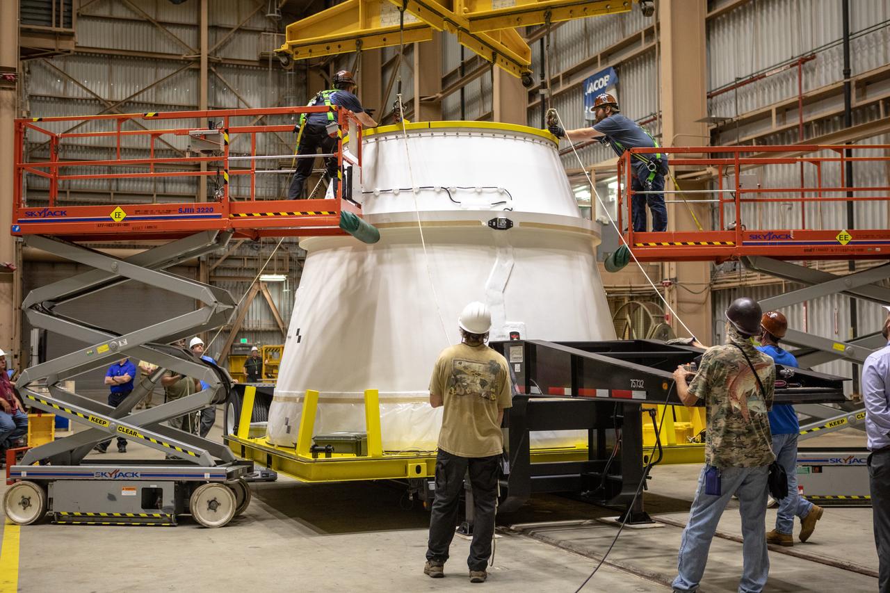
Workers assist with removal of the shipping container cover from the first Northrop Grumman aft exit cone to arrive for the Space Launch System’s solid rocket boosters inside the Rotation, Processing and Surge Facility at NASA’s Kennedy Space Center in Florida on Nov. 4, 2019. The aft exit cone was shipped from Promontory, Utah. It will be checked out and prepared for the Artemis I uncrewed test flight. The aft exit cones sit at the bottommost part of the twin boosters. They are attached to the aft skirts, which contain the booster separation motors. The exit cones help to protect the aft skirts during launch.
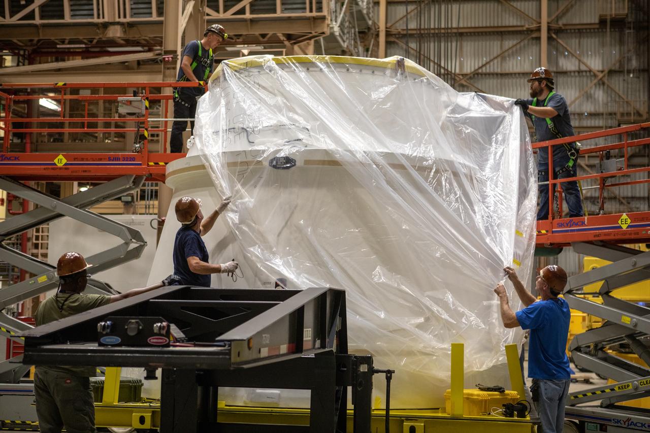
Workers remove the protective cover from the first Northrop Grumman aft exit cone to arrive for the Space Launch System’s solid rocket boosters inside the Rotation, Processing and Surge Facility at NASA’s Kennedy Space Center in Florida on Nov. 4, 2019. The aft exit cone was shipped from Promontory, Utah. It will be checked out and prepared for the Artemis I uncrewed test flight. The aft exit cones sit at the bottommost part of the twin boosters. They are attached to the aft skirts, which contain the booster separation motors. The exit cones help to protect the aft skirts during launch.
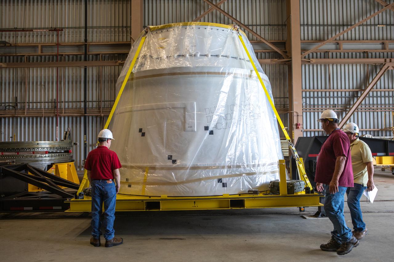
The shipping container cover has been removed from the first Northrop Grumman aft exit cone to arrive for the Space Launch System’s solid rocket boosters inside the Rotation, Processing and Surge Facility at NASA’s Kennedy Space Center in Florida on Nov. 4, 2019. The aft exit cone was shipped from Promontory, Utah. It will be checked out and prepared for the Artemis I uncrewed test flight. The aft exit cones sit at the bottommost part of the twin boosters. They are attached to the aft skirts, which contain the booster separation motors. The exit cones help to protect the aft skirts during launch.
The first Northrop Grumman aft exit cone to arrive for the Space Launch System’s solid rocket boosters is moved by crane inside the Rotation, Processing and Surge Facility at NASA’s Kennedy Space Center in Florida on Nov. 4, 2019. The aft exit cone was shipped from Promontory, Utah. It will be checked out and prepared for the Artemis I uncrewed test flight. The aft exit cones sit at the bottommost part of the twin boosters. They are attached to the aft skirts, which contain the booster separation motors. The exit cones help to protect the aft skirts during launch.
KENNEDY SPACE CENTER, FLA. - In the Vehicle Assembly Building (VAB), a segment of a Solid Rocket Booster (SRB) is lifted to the 16th level. This right aft center segment will be stacked with the aft booster that arrived in the VAB Nov. 22 for the Return to Flight mission STS-114. Two SRBs are stacked on the Mobile Launch Platform and later joined by the External Tank. The twin 149-foot tall, 12-foot diameter SRBs provide the main propulsion system during launch. They operate parallel with the Space Shuttle main engines for the first two minutes of flight and jettison away from the orbiter with help from the Booster Separation Motors, about 26.3 nautical miles above the Earth’s surface.
Workers assist as a crane is used to lift up the shipping container cover from the first Northrop Grumman aft exit cone to arrive for the Space Launch System’s solid rocket boosters inside the Rotation, Processing and Surge Facility at NASA’s Kennedy Space Center in Florida on Nov. 4, 2019. The aft exit cone was shipped from Promontory, Utah. It will be checked out and prepared for the Artemis I uncrewed test flight. The aft exit cones sit at the bottommost part of the twin boosters. They are attached to the aft skirts, which contain the booster separation motors. The exit cones help to protect the aft skirts during launch.
Workers attach a crane to the first Northrop Grumman aft exit cone to arrive for the Space Launch System’s solid rocket boosters inside the Rotation, Processing and Surge Facility at NASA’s Kennedy Space Center in Florida on Nov. 4, 2019. The aft exit cone was shipped from Promontory, Utah. It will be checked out and prepared for the Artemis I uncrewed test flight. The aft exit cones sit at the bottommost part of the twin boosters. They are attached to the aft skirts, which contain the booster separation motors. The exit cones help to protect the aft skirts during launch.
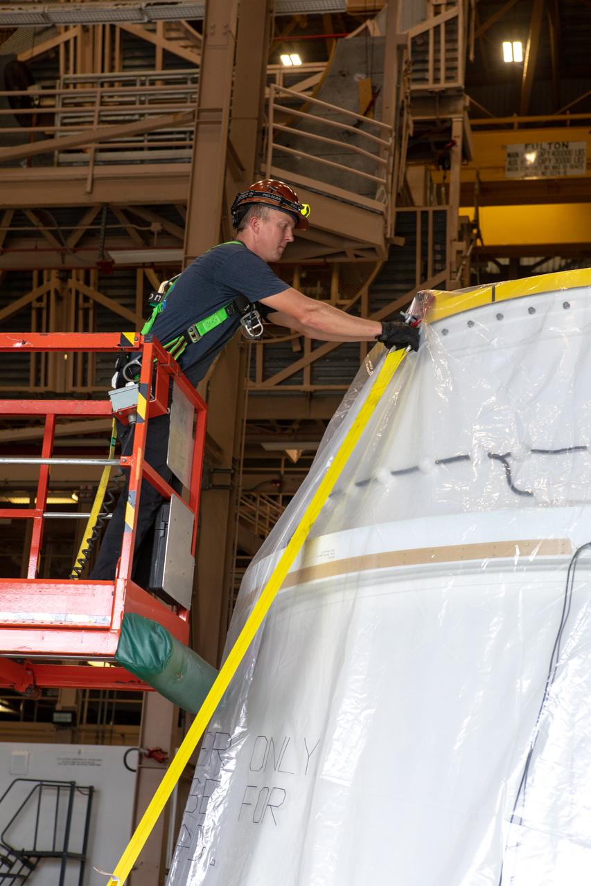
A worker removes one of the securing straps from the first Northrop Grumman aft exit cone to arrive for the Space Launch System’s solid rocket boosters inside the Rotation, Processing and Surge Facility at NASA’s Kennedy Space Center in Florida on Nov. 4, 2019. The aft exit cone was shipped from Promontory, Utah. It will be checked out and prepared for the Artemis I uncrewed test flight. The aft exit cones sit at the bottommost part of the twin boosters. They are attached to the aft skirts, which contain the booster separation motors. The exit cones help to protect the aft skirts during launch.
Workers assist with removal of the shipping container cover from the first Northrop Grumman aft exit cone to arrive for the Space Launch System’s solid rocket boosters inside the Rotation, Processing and Surge Facility at NASA’s Kennedy Space Center in Florida on Nov. 4, 2019. The aft exit cone was shipped from Promontory, Utah. It will be checked out and prepared for the Artemis I uncrewed test flight. The aft exit cones sit at the bottommost part of the twin boosters. They are attached to the aft skirts, which contain the booster separation motors. The exit cones help to protect the aft skirts during launch.
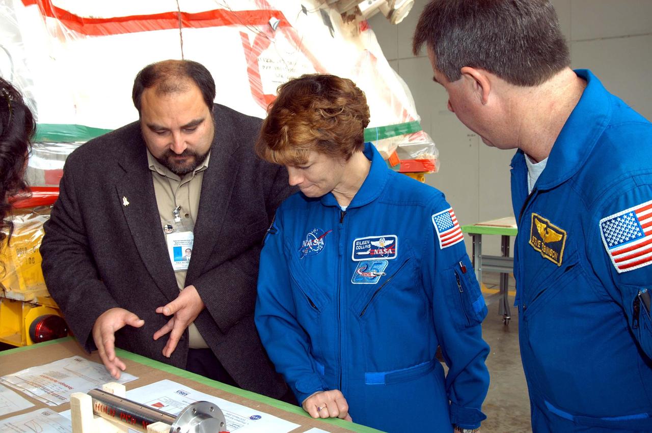
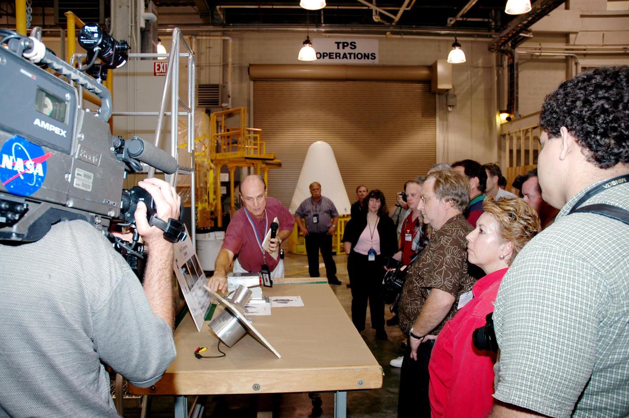
KENNEDY SPACE CENTER, FLA. - At the SRB Assembly and Refurbishment Facility, STS-114 Eileen Collins (center) and Mission Specialist Stephen Robinson look on the table at a mockup of a booster separation motor (BSM) igniter and expanded views of the BSM and igniter. At left is Paul Gutierrez, SRB associate program manager with United Space Alliance. The crew is at KSC for familiarization with Shuttle and mission equipment. The STS-114 mission is Logistics Flight 1, which is scheduled to deliver supplies and equipment, plus the external stowage platform, to the International Space Station.

KENNEDY SPACE CENTER, FLA. - At the SRB Assembly and Refurbishment Facility, STS-114 Mission Specialist Soichi Noguchi looks at a mockup of a booster separation motor (BSM) igniter. Noguchi is with the Japanese Aerospace and Exploration Agency. The crew is at KSC for familiarization with Shuttle and mission equipment. The STS-114 mission is Logistics Flight 1, which is scheduled to deliver supplies and equipment, plus the external stowage platform, to the International Space Station.

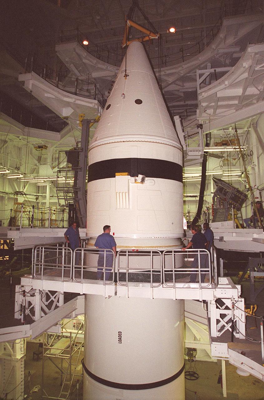
Workers in the Vehicle Assembly Building check the connections on the forward section of a solid rocket booster (SRB) being mated to the rest of the stack below it. The forward section of each booster, from nose cap to forward skirt contains avionics, a sequencer, forward separation motors, a nose cone separation system, drogue and main parachutes, a recovery beacon, a recovery light, a parachute camera on selected flights and a range safety system. Each SRB weighs approximately 1.3 million pounds at launch. The SRB is part of the stack for Space Shuttle Discovery and the STS-92 mission, scheduled for launch Oct. 5, from Launch Pad 39A, on the fifth flight to the International Space Station. Payloads on the mission include the Z-1 truss and Pressurized Mating Adapter-3, components of the Space Station
Workers in the Vehicle Assembly Building check the connections on the forward section of a solid rocket booster (SRB) being mated to the rest of the stack below it. The forward section of each booster, from nose cap to forward skirt contains avionics, a sequencer, forward separation motors, a nose cone separation system, drogue and main parachutes, a recovery beacon, a recovery light, a parachute camera on selected flights and a range safety system. Each SRB weighs approximately 1.3 million pounds at launch. The SRB is part of the stack for Space Shuttle Discovery and the STS-92 mission, scheduled for launch Oct. 5, from Launch Pad 39A, on the fifth flight to the International Space Station. Payloads on the mission include the Z-1 truss and Pressurized Mating Adapter-3, components of the Space Station

Workers in the Vehicle Assembly Building check the connections on the forward section of a solid rocket booster (SRB) being mated to the rest of the stack below it. The forward section of each booster, from nose cap to forward skirt contains avionics, a sequencer, forward separation motors, a nose cone separation system, drogue and main parachutes, a recovery beacon, a recovery light, a parachute camera on selected flights and a range safety system. Each SRB weighs approximately 1.3 million pounds at launch. The SRB is part of the stack for Space Shuttle Discovery and the STS-92 mission, scheduled for launch Oct. 5, from Launch Pad 39A, on the fifth flight to the International Space Station. Payloads on the mission include the Z-1 truss and Pressurized Mating Adapter-3, components of the Space Station
Workers in the Vehicle Assembly Building check the connections on the forward section of a solid rocket booster (SRB) being mated to the rest of the stack below it. The forward section of each booster, from nose cap to forward skirt contains avionics, a sequencer, forward separation motors, a nose cone separation system, drogue and main parachutes, a recovery beacon, a recovery light, a parachute camera on selected flights and a range safety system. Each SRB weighs approximately 1.3 million pounds at launch. The SRB is part of the stack for Space Shuttle Discovery and the STS-92 mission, scheduled for launch Oct. 5, from Launch Pad 39A, on the fifth flight to the International Space Station. Payloads on the mission include the Z-1 truss and Pressurized Mating Adapter-3, components of the Space Station
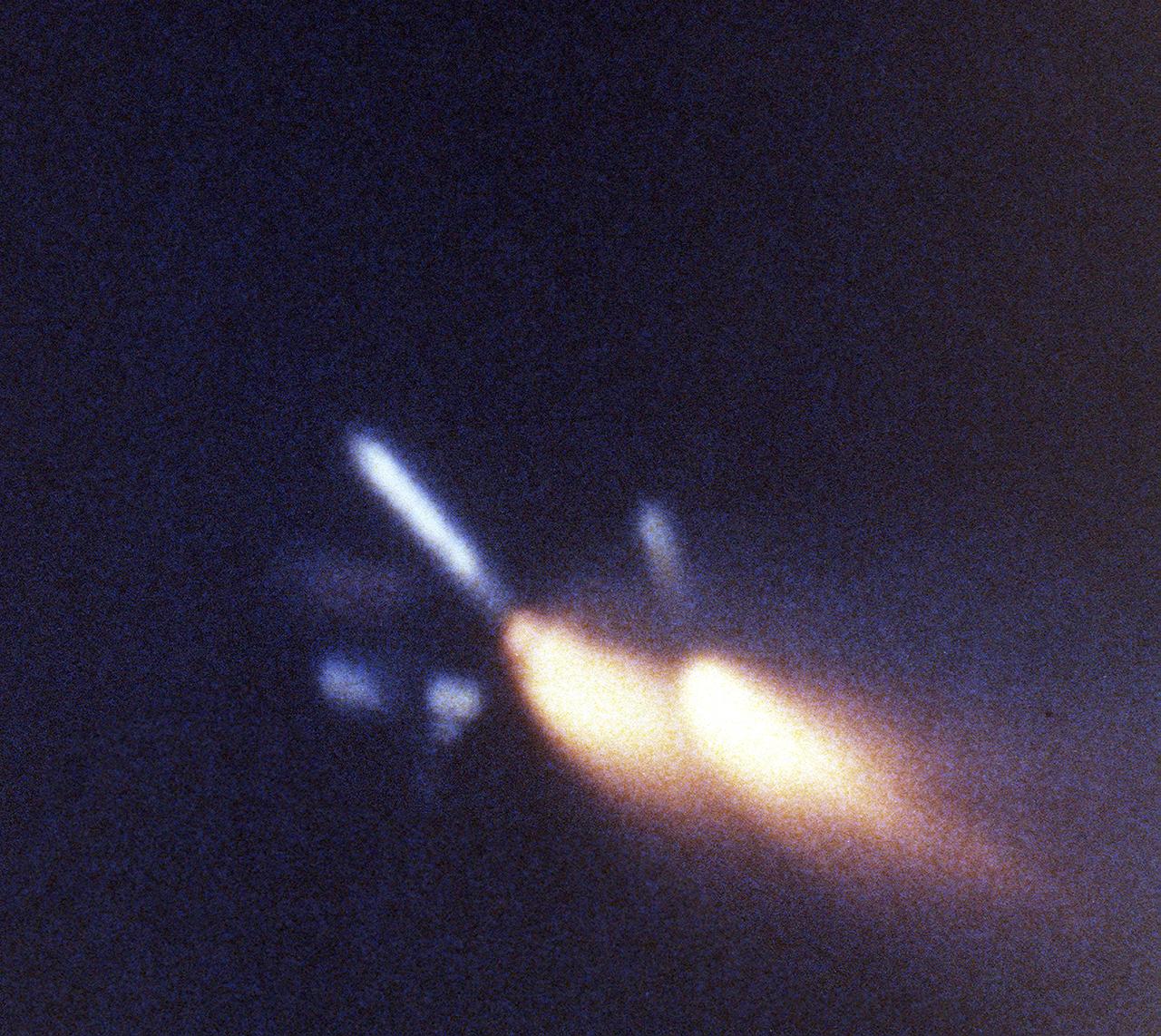
This view, taken by a motion picture tracking camera for the STS-3 mission, shows both left and right solid rocket boosters (SRB's) at the moment of separation from the external tank (ET). After impact to the ocean, they were retrieved and refurbished for reuse. The Shuttle's SRB's and solid rocket motors (SRM's) are the largest ever built and the first designed for refurbishment and reuse. Standing nearly 150-feet high, the twin boosters provide the majority of thrust for the first two minutes of flight, about 5.8 million pounds. That is equivalent to 44 million horsepower, or the combined power of 400,000 subcompact cars.
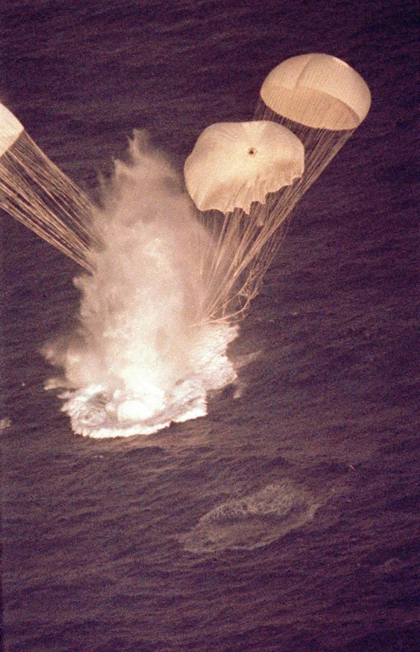
he left solid rocket booster (SRB) for the STS-5 mission is shown in this photograph at the moment of splashdown after its separation from the external tank. This view was photographed from a Cast Glance aircraft. After impact to the ocean, it was retrieved and refurbished for reuse. The Shuttle's SRB's and solid rocket motors (SRM's) are the largest ever built and the first designed for refurbishment and reuse. Standing nearly 150-feet high, the twin boosters provide the majority of thrust for the first two minutes of flight, about 5.8 million pounds. That is equivalent to 44 million horsepower, or the combined power of 400,000 subcompact cars.
KENNEDY SPACE CENTER, FLA. - Inside the Vehicle Assembly Building, media are shown where the aft skirt and lower segment of the Solid Rocket Booster for the Return to Flight mission STS-114 will be stacked with other segments to follow. Two SRBs support the liftoff of the Space Shuttle on a launch. The twin 149-foot tall, 12-foot diameter SRBs provide the main propulsion system during launch to place the 180,000-pound orbiters in the proper orbit around the Earth. They operate parallel with the Space Shuttle main engines for the first two minutes of flight and jettison away from the orbiter with help from the Booster Separation Motors, about 26.3 nautical miles above the Earth’s surface.
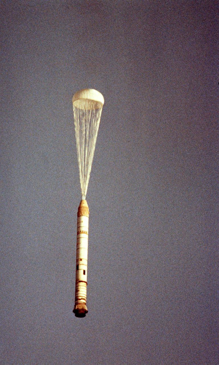
The right solid rocket booster (SRB) for the STS-5 mission, with one chute opened, falls after its separation from the external tank (ET). This view was photographed from a Cast Glance aircraft. After impact to the ocean, it was retrieved and refurbished for reuse. The Shuttle's SRB's and solid rocket motors (SRM's) are the largest ever built and the first designed for refurbishment and reuse. Standing nearly 150-feet high, the twin boosters provide the majority of thrust for the first two minutes of flight, about 5.8 million pounds. That is equivalent to 44 million horsepower, or the combined power of 400,000 subcompact cars.
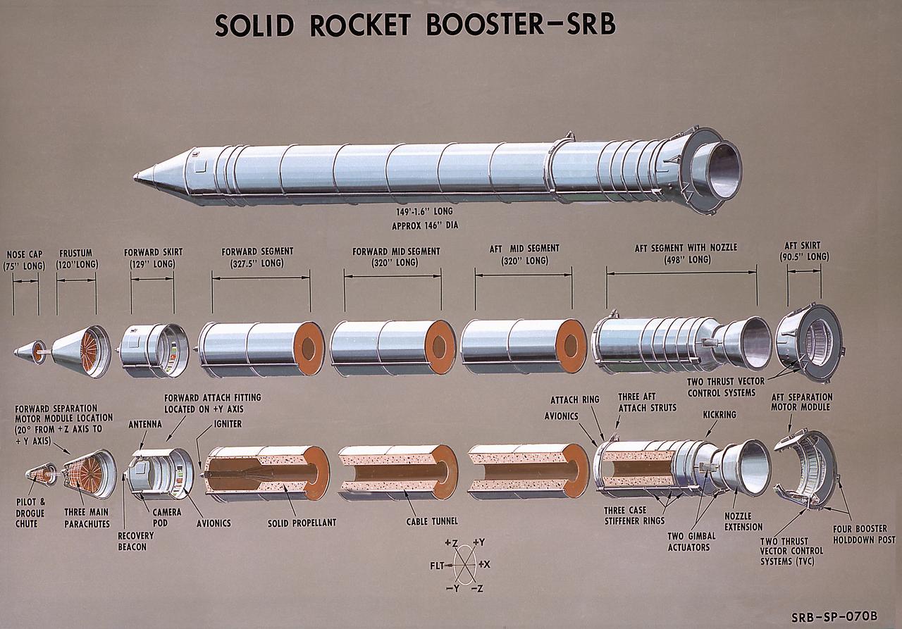
This illustration is a cutaway of the solid rocket booster (SRB) sections with callouts. The Shuttle's two SRB's are the largest solids ever built and the first designed for refurbishment and reuse. Standing nearly 150-feet high, the twin boosters provide the majority of thrust for the first two minutes of flight, about 5.8 million pounds, augmenting the Shuttle's main propulsion system during liftoff. The major design drivers for the solid rocket motors (SRM's) were high thrust and reuse. The desired thrust was achieved by using state-of-the-art solid propellant and by using a long cylindrical motor with a specific core design that allows the propellant to burn in a carefully controlled marner. At burnout, the boosters separate from the external tank and drop by parachute to the ocean for recovery and subsequent refurbishment. The boosters are designed to survive water impact at almost 60 miles per hour, maintain flotation with minimal damage, and preclude corrosion of the hardware exposed to the harsh seawater environment. Under the project management of the Marshall Space Flight Center, the SRB's are assembled and refurbished by the United Space Boosters. The SRM's are provided by the Morton Thiokol Corporation.
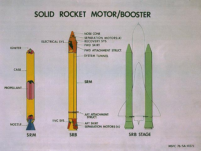
This image illustrates the solid rocket motor (SRM)/solid rocket booster (SRB) configuration. The Shuttle's two SRB's are the largest solids ever built and the first designed for refurbishment and reuse. Standing nearly 150-feet high, the twin boosters provide the majority of thrust for the first two minutes of flight, about 5.8 million pounds, augmenting the Shuttle's main propulsion system during liftoff. The major design drivers for the SRM's were high thrust and reuse. The desired thrust was achieved by using state-of-the-art solid propellant and by using a long cylindrical motor with a specific core design that allows the propellant to burn in a carefully controlled marner. At burnout, the boosters separate from the external tank and drop by parachute to the ocean for recovery and subsequent refurbishment. The boosters are designed to survive water impact at almost 60 miles per hour, maintain flotation with minimal damage, and preclude corrosion of the hardware exposed to the harsh seawater environment. Under the project management of the Marshall Space Flight Center, the SRB's are assembled and refurbished by the United Space Boosters. The SRM's are provided by the Morton Thiokol Corporation.
CAPE CANAVERAL, Fla. – In the Assembly and Refurbishment Facility at NASA's Kennedy Space Center, the aft skirt for the Ares 1-X rocket has been lowered onto another stand. The segment is being moved onto a machine shop work stand for drilling modifications. The modifications will prepare it for the installation of the auxiliary power unit controller, the reduced-rate gyro unit, the booster decelerator motors and the booster tumble motors. Ares I is an in-line, two-stage rocket that will transport the Orion crew exploration vehicle to low-Earth orbit. Ares I-X is a test rocket. The Ares I first stage will be a five-segment solid rocket booster based on the four-segment design used for the shuttle. Ares I’s fifth booster segment allows the launch vehicle to lift more weight and reach a higher altitude before the first stage separates from the upper stage, which ignites in midflight to propel the Orion spacecraft to Earth orbit. Photo credit: NASA/Jim Grossmann
CAPE CANAVERAL, Fla. – In the Assembly and Refurbishment Facility at NASA's Kennedy Space Center, a worker attaches an overhead crane to the aft skirt for the Ares 1-X rocket. The segment is being lifted into a machine shop work stand for drilling modifications. The modifications will prepare it for the installation of the auxiliary power unit controller, the reduced-rate gyro unit, the booster decelerator motors and the booster tumble motors. Ares I is an in-line, two-stage rocket that will transport the Orion crew exploration vehicle to low-Earth orbit. Ares I-X is a test rocket. The Ares I first stage will be a five-segment solid rocket booster based on the four-segment design used for the shuttle. Ares I’s fifth booster segment allows the launch vehicle to lift more weight and reach a higher altitude before the first stage separates from the upper stage, which ignites in midflight to propel the Orion spacecraft to Earth orbit. Photo credit: NASA/Jim Grossmann
CAPE CANAVERAL, Fla. – In the Assembly and Refurbishment Facility at NASA's Kennedy Space Center, workers help guide the aft skirt for the Ares 1-X rocket as it is moved. The segment is being lifted into a machine shop work stand for drilling modifications. The modifications will prepare it for the installation of the auxiliary power unit controller, the reduced-rate gyro unit, the booster decelerator motors and the booster tumble motors. Ares I is an in-line, two-stage rocket that will transport the Orion crew exploration vehicle to low-Earth orbit. Ares I-X is a test rocket. The Ares I first stage will be a five-segment solid rocket booster based on the four-segment design used for the shuttle. Ares I’s fifth booster segment allows the launch vehicle to lift more weight and reach a higher altitude before the first stage separates from the upper stage, which ignites in midflight to propel the Orion spacecraft to Earth orbit. Photo credit: NASA/Jim Grossmann
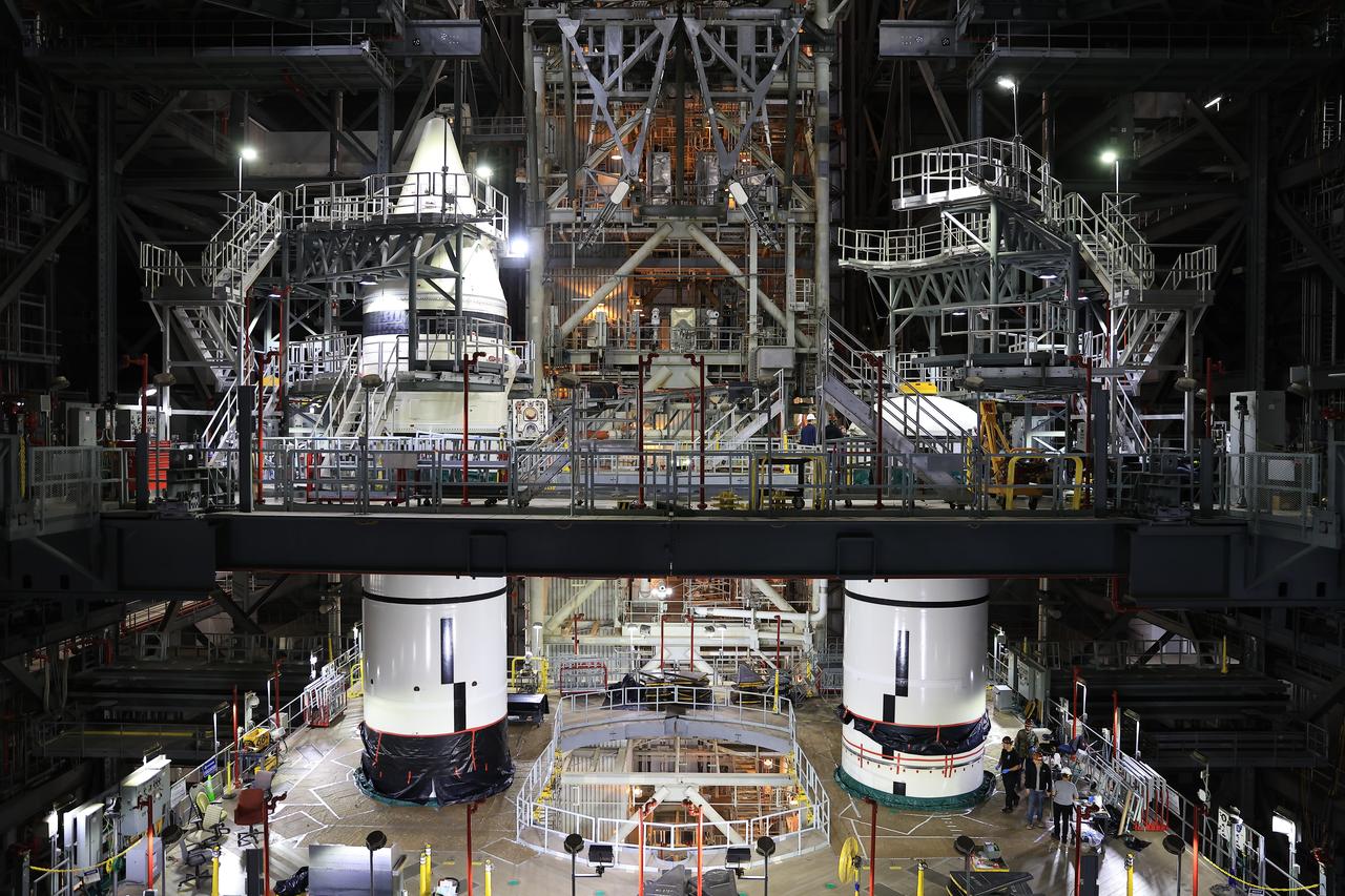
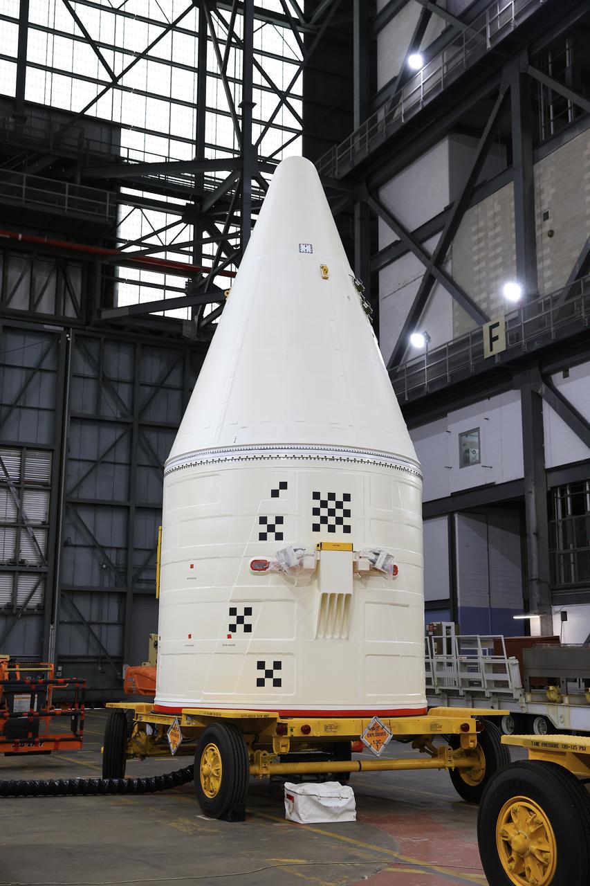
Engineers with NASA’s Exploration Ground Systems integrate the aerodynamic nose cone onto the left-hand forward assembly on the twin SLS (Space Launch System) solid rocket boosters for Artemis II inside the Vehicle Assembly Building’s High Bay 3 at NASA’s Kennedy Space Center in Florida on Tuesday, Feb. 18, 2025. Each forward assembly contains an aerodynamic top, a forward skirt housing avionics, and frustum housing motors that allow the boosters to separate from the SLS core stage after launch. The twin solid boosters will help support the remaining rocket components and the Orion spacecraft during final assembly of the Artemis II Moon rocket and provide more than 75 percent of the total SLS thrust during liftoff from NASA Kennedy’s Launch Pad 39B.
KENNEDY SPACE CENTER, FLA. - In the transfer aisle of the Vehicle Assembly Building (VAB), a segment of a Solid Rocket Booster (SRB) is lifted from a transporter toward the 16th level. This right aft center segment will be stacked with the aft booster that arrived in the VAB Nov. 22 for the Return to Flight mission STS-114. Two SRBs are stacked on the Mobile Launch Platform and later joined by the External Tank.. The twin 149-foot tall, 12-foot diameter SRBs provide the main propulsion system during launch. They operate parallel with the Space Shuttle main engines for the first two minutes of flight and jettison away from the orbiter with help from the Booster Separation Motors, about 26.3 nautical miles above the Earth’s surface.
Engineers with NASA’s Exploration Ground Systems integrate the aerodynamic nose cone onto the left-hand forward assembly on the twin SLS (Space Launch System) solid rocket boosters for Artemis II inside the Vehicle Assembly Building’s High Bay 3 at NASA’s Kennedy Space Center in Florida on Tuesday, Feb. 18, 2025. Each forward assembly contains an aerodynamic top, a forward skirt housing avionics, and frustum housing motors that allow the boosters to separate from the SLS core stage after launch. The twin solid boosters will help support the remaining rocket components and the Orion spacecraft during final assembly of the Artemis II Moon rocket and provide more than 75 percent of the total SLS thrust during liftoff from NASA Kennedy’s Launch Pad 39B.
KENNEDY SPACE CENTER, FLA. - In the Vehicle Assembly Building (VAB), a segment of a Solid Rocket Booster (SRB) is lifted over the cross walk at the 16th level. This right aft center segment will be stacked with the aft booster on the other side that arrived in the VAB Nov. 22 for the Return to Flight mission STS-114. Two SRBs are stacked on the Mobile Launch Platform and later joined by the External Tank.. The twin 149-foot tall, 12-foot diameter SRBs provide the main propulsion system during launch. They operate parallel with the Space Shuttle main engines for the first two minutes of flight and jettison away from the orbiter with help from the Booster Separation Motors, about 26.3 nautical miles above the Earth’s surface.
KENNEDY SPACE CENTER, FLA. - In the Vehicle Assembly Building (VAB), a segment of a Solid Rocket Booster (SRB) is lifted over the cross walk at the 16th level. This right aft center segment will be stacked with the aft booster on the other side that arrived in the VAB Nov. 22 for the Return to Flight mission STS-114. Two SRBs are stacked on the Mobile Launch Platform and later joined by the External Tank.. The twin 149-foot tall, 12-foot diameter SRBs provide the main propulsion system during launch. They operate parallel with the Space Shuttle main engines for the first two minutes of flight and jettison away from the orbiter with help from the Booster Separation Motors, about 26.3 nautical miles above the Earth’s surface.
Engineers with NASA’s Exploration Ground Systems integrate the aerodynamic nose cone onto the right-hand forward assembly of the twin SLS (Space Launch System) solid rocket boosters for Artemis II inside the Vehicle Assembly Building’s High Bay 3 at NASA’s Kennedy Space Center in Florida on Tuesday, Feb. 18, 2025. Each forward assembly contains an aerodynamic top, a forward skirt housing avionics, and frustum housing motors that allow the boosters to separate from the SLS core stage after launch. The twin solid boosters will help support the remaining rocket components and the Orion spacecraft during final assembly of the Artemis II Moon rocket and provide more than 75 percent of the total SLS thrust during liftoff from NASA Kennedy’s Launch Pad 39B.
KENNEDY SPACE CENTER, FLA. - The media tour Solid Rocket Booster (SRB) Assembly and Refurbishment Facility where Solid Rocket Booster (SRB) segments are refurbished. In the background can be seen the frustum and nose cap of an SRB. The media event featured the movement of the first SRB segments to the Vehicle Assembly Building for stacking for Return to Flight mission STS-114. Two SRBs support the liftoff of the Space Shuttle on a launch. The twin 149-foot tall, 12-foot diameter SRBs provide the main propulsion system during launch to place the orbiters in the proper orbit around the Earth. They operate parallel with the Space Shuttle main engines for the first two minutes of flight and jettison away from the orbiter, with help from the Booster Separation Motors, about 26.3 nautical miles above the Earth’s surface.
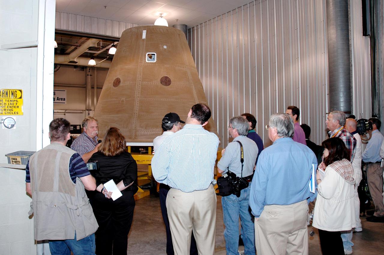
KENNEDY SPACE CENTER, FLA. - The media tour Solid Rocket Booster (SRB) Assembly and Refurbishment Facility where Solid Rocket Booster (SRB) segments are refurbished. In the background can be seen the frustum and nose cap of an SRB. The media event featured the movement of the first SRB segments to the Vehicle Assembly Building for stacking for Return to Flight mission STS-114. Two SRBs support the liftoff of the Space Shuttle on a launch. The twin 149-foot tall, 12-foot diameter SRBs provide the main propulsion system during launch to place the orbiters in the proper orbit around the Earth. They operate parallel with the Space Shuttle main engines for the first two minutes of flight and jettison away from the orbiter, with help from the Booster Separation Motors, about 26.3 nautical miles above the Earth’s surface.
KENNEDY SPACE CENTER, FLA. - In the transfer aisle of the Vehicle Assembly Building (VAB), a segment of a Solid Rocket Booster (SRB) is lifted from a transporter toward the 16th level. This right aft center segment will be stacked with the aft booster that arrived in the VAB Nov. 22 for the Return to Flight mission STS-114. Two SRBs are stacked on the Mobile Launch Platform and later joined by the External Tank.. The twin 149-foot tall, 12-foot diameter SRBs provide the main propulsion system during launch. They operate parallel with the Space Shuttle main engines for the first two minutes of flight and jettison away from the orbiter with help from the Booster Separation Motors, about 26.3 nautical miles above the Earth’s surface.

Engineers with NASA’s Exploration Ground Systems integrate the aerodynamic nose cone onto the left-hand forward assembly on the twin SLS (Space Launch System) solid rocket boosters for Artemis II inside the Vehicle Assembly Building’s High Bay 3 at NASA’s Kennedy Space Center in Florida on Tuesday, Feb. 18, 2025. Each forward assembly contains an aerodynamic top, a forward skirt housing avionics, and frustum housing motors that allow the boosters to separate from the SLS core stage after launch. The twin solid boosters will help support the remaining rocket components and the Orion spacecraft during final assembly of the Artemis II Moon rocket and provide more than 75 percent of the total SLS thrust during liftoff from NASA Kennedy’s Launch Pad 39B.
Engineers with NASA’s Exploration Ground Systems integrate the aerodynamic nose cone onto the right-hand forward assembly of the twin SLS (Space Launch System) solid rocket boosters for Artemis II inside the Vehicle Assembly Building’s High Bay 3 at NASA’s Kennedy Space Center in Florida on Tuesday, Feb. 18, 2025. Each forward assembly contains an aerodynamic top, a forward skirt housing avionics, and frustum housing motors that allow the boosters to separate from the SLS core stage after launch. The twin solid boosters will help support the remaining rocket components and the Orion spacecraft during final assembly of the Artemis II Moon rocket and provide more than 75 percent of the total SLS thrust during liftoff from NASA Kennedy’s Launch Pad 39B.
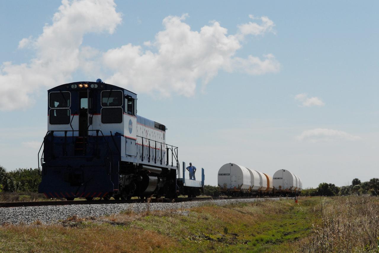
CAPE CANAVERAL, Fla. –The cars on the NASA Railroad are separated for different destinations at NASA's Kennedy Space Center in Florida. They carry Ares I-X segments. One of the cars is going to the Rotation, Processing and Surge Facility. The four reusable motor segments and the nozzle exit cone, manufactured by the Ares I first-stage prime contractor Alliant Techsystems Inc., or ATK, departed Utah March 12 on the seven-day, cross-country trip to Florida. The segments will be delivered to Kennedy's Rotation, Processing and Surge Facility for final processing and integration. The booster used for the Ares I-X launch is being modified by adding new forward structures and a fifth segment simulator. The motor is the final hardware needed for the rocket's upcoming test flight this summer. The stacking operations are scheduled to begin in the Vehicle Assembly Building in April. Photo credit: NASA/Jack Pfaller
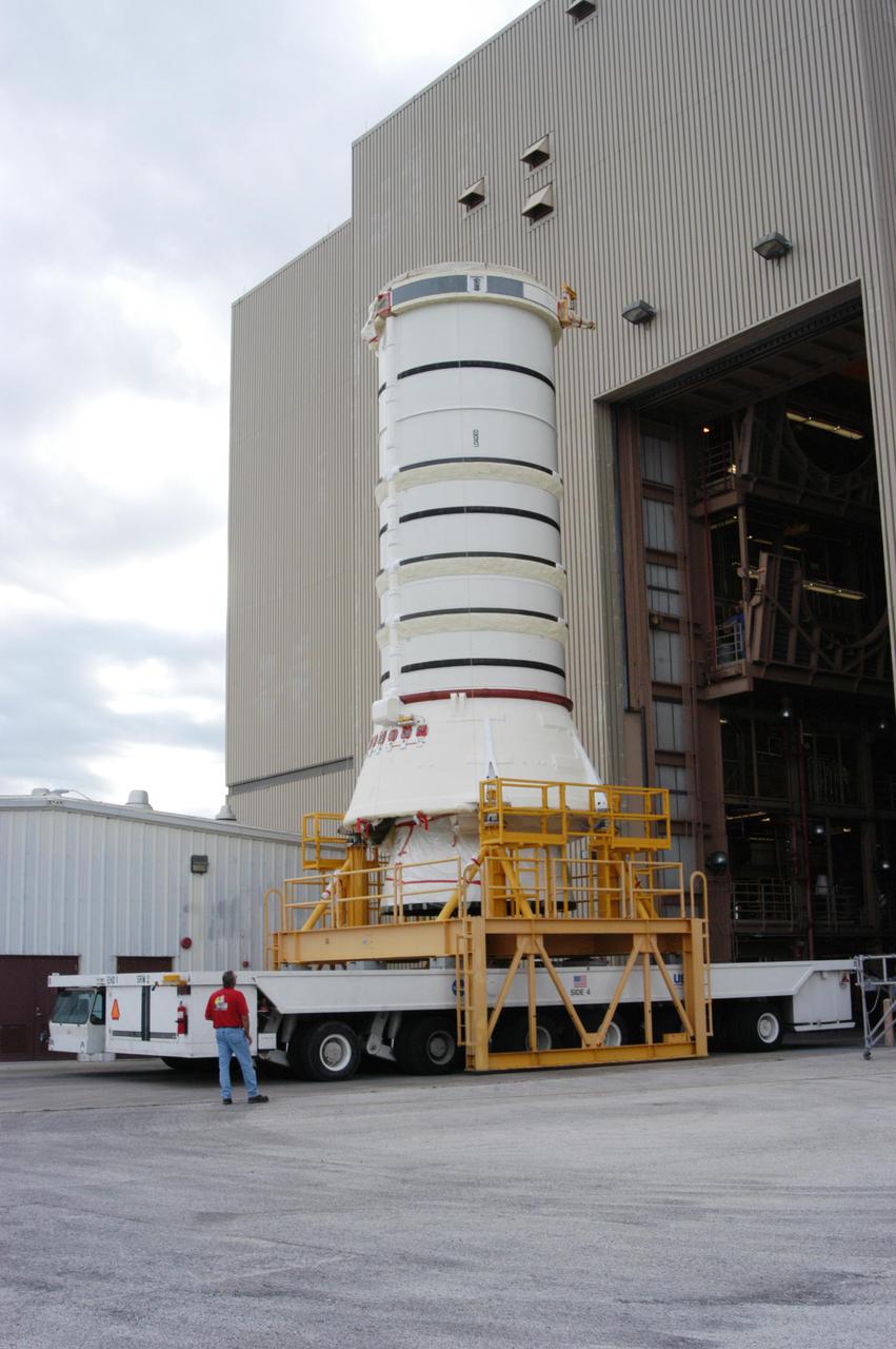
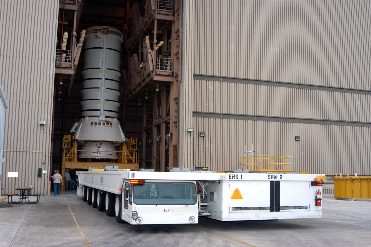
KENNEDY SPACE CENTER, FLA. - The aft skirt and lower segment of the Solid Rocket Booster (SRB) being prepared for Return to Flight on mission STS-114 leave the Rotation Processing and Surge Facility. The segments are being transported to the Vehicle Assembly Building where they will be prepared for stacking with the other segments arriving later. Two SRBs support the liftoff of the Space Shuttle on a launch. The twin 149-foot tall, 12-foot diameter SRBs provide the main propulsion system during launch to place the 180,000-pound orbiters in the proper orbit around the Earth. They operate parallel with the Space Shuttle main engines for the first two minutes of flight and jettison away from the orbiter with help from the Booster Separation Motors, about 26.3 nautical miles above the Earth’s surface.
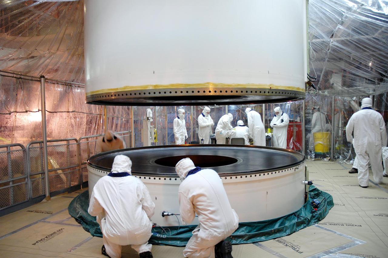
KENNEDY SPACE CENTER, FLA. - In a Vehicle Assembly Building (VAB) high bay, an aft center segment of a Solid Rocket Booster (SRB) is lowered toward an aft segment already secured to a Mobile Launch Platform. These segments are part of the right SRB for the Space Shuttle Return to Flight mission, STS-114. Two SRBs are stacked on a Mobile Launch Platform for each Shuttle flight and later joined by an External Tank. The twin 149-foot tall, 12-foot diameter SRBs provide the main propulsion system during launch. They operate in parallel with the Space Shuttle main engines for the first two minutes of flight and jettison away from the orbiter with help from the Booster Separation Motors, about 26.3 nautical miles above the Earth’s surface.
KENNEDY SPACE CENTER, FLA. - The transporter arrives at the Rotation Processing and Surge Facility to move the aft skirt and lower segment of the Solid Rocket Booster (SRB) to the Vehicle Assembly. These segments are the first to be prepared for Return to Flight on mission STS-114. Other segments will follow for stacking. Two SRBs support the liftoff of the Space Shuttle on a launch. The twin 149-foot tall, 12-foot diameter SRBs provide the main propulsion system during launch to place the 180,000-pound orbiters in the proper orbit around the Earth. They operate parallel with the Space Shuttle main engines for the first two minutes of flight and jettison away from the orbiter with help from the Booster Separation Motors, about 26.3 nautical miles above the Earth’s surface.
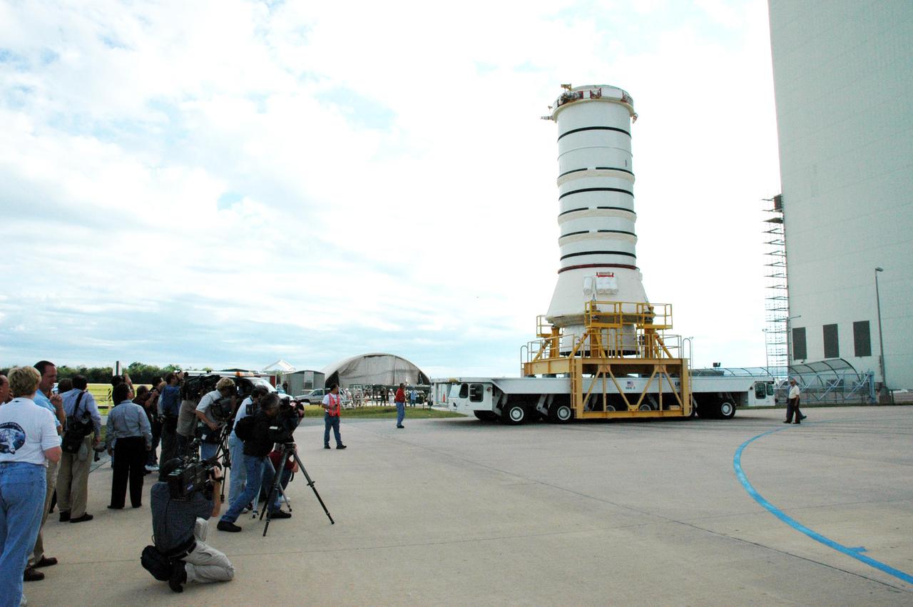
KENNEDY SPACE CENTER, FLA. - The media station their cameras to capture the move of the aft skirt and lower segment of the Solid Rocket Booster for the Return to Flight mission STS-114. A significant milestone in Return to Flight preparations, these first segments are moving from the Rotation Processing and Surge Facility to the Vehicle Assembly Building. Other segments will follow for stacking. Two SRBs support the liftoff of the Space Shuttle on a launch. The twin 149-foot tall, 12-foot diameter SRBs provide the main propulsion system during launch to place the 180,000-pound orbiters in the proper orbit around the Earth. They operate parallel with the Space Shuttle main engines for the first two minutes of flight and jettison away from the orbiter with help from the Booster Separation Motors, about 26.3 nautical miles above the Earth’s surface.
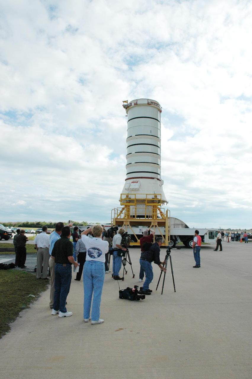
KENNEDY SPACE CENTER, FLA. - - The media station their cameras to capture the move of the aft skirt and lower segment of the Solid Rocket Booster for the Return to Flight mission STS-114. A significant milestone in Return to Flight, these first segments are moving from the Rotation Processing and Surge Facility to the Vehicle Assembly Building. Other segments will follow for stacking. Two SRBs support the liftoff of the Space Shuttle on a launch. The twin 149-foot tall, 12-foot diameter SRBs provide the main propulsion system during launch to place the 180,000-pound orbiters in the proper orbit around the Earth. They operate parallel with the Space Shuttle main engines for the first two minutes of flight and jettison away from the orbiter with help from the Booster Separation Motors, about 26.3 nautical miles above the Earth’s surface.
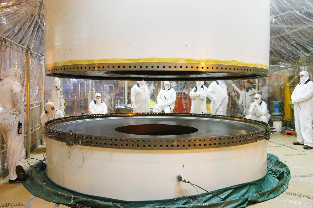
KENNEDY SPACE CENTER, FLA. - In a Vehicle Assembly Building (VAB) high bay, an aft center segment of a Solid Rocket Booster (SRB) continues its descent toward an aft segment already secured to a Mobile Launch Platform. These segments are part of the right SRB for the Space Shuttle Return to Flight mission, STS-114. Two SRBs are stacked on a Mobile Launch Platform for each Shuttle flight and later joined by an External Tank. The twin 149-foot tall, 12-foot diameter SRBs provide the main propulsion system during launch. They operate in parallel with the Space Shuttle main engines for the first two minutes of flight and jettison away from the orbiter with help from the Booster Separation Motors, about 26.3 nautical miles above the Earth’s surface.
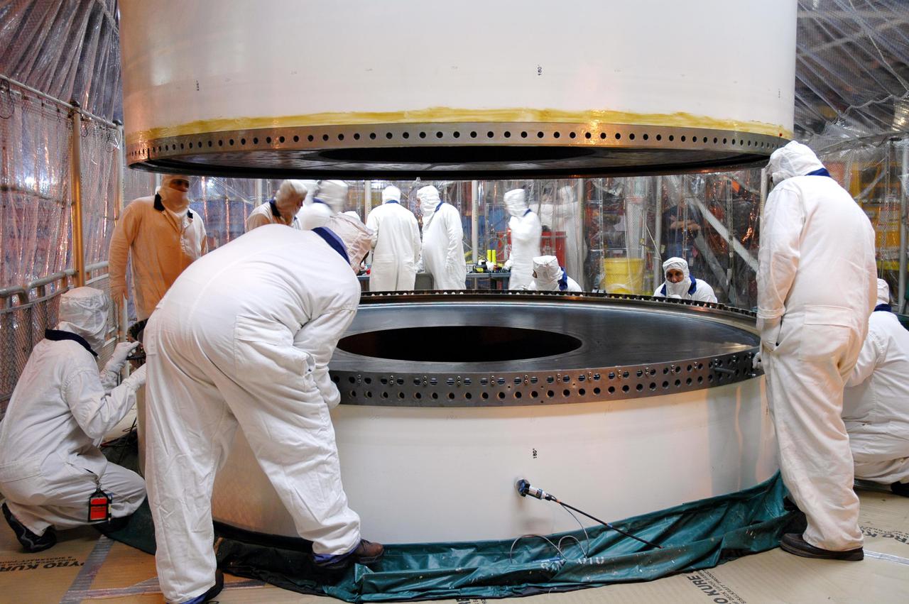
KENNEDY SPACE CENTER, FLA. - In a Vehicle Assembly Building (VAB) high bay, workers monitor the movement of a Solid Rocket Booster (SRB) aft center segment as it is lowered toward an aft segment already secured to a Mobile Launch Platform. These segments are part of the right SRB for the Space Shuttle Return to Flight mission, STS-114. Two SRBs are stacked on a Mobile Launch Platform for each Shuttle flight and later joined by an External Tank. The twin 149-foot tall, 12-foot diameter SRBs provide the main propulsion system during launch. They operate in parallel with the Space Shuttle main engines for the first two minutes of flight and jettison away from the orbiter with help from the Booster Separation Motors, about 26.3 nautical miles above the Earth’s surface.
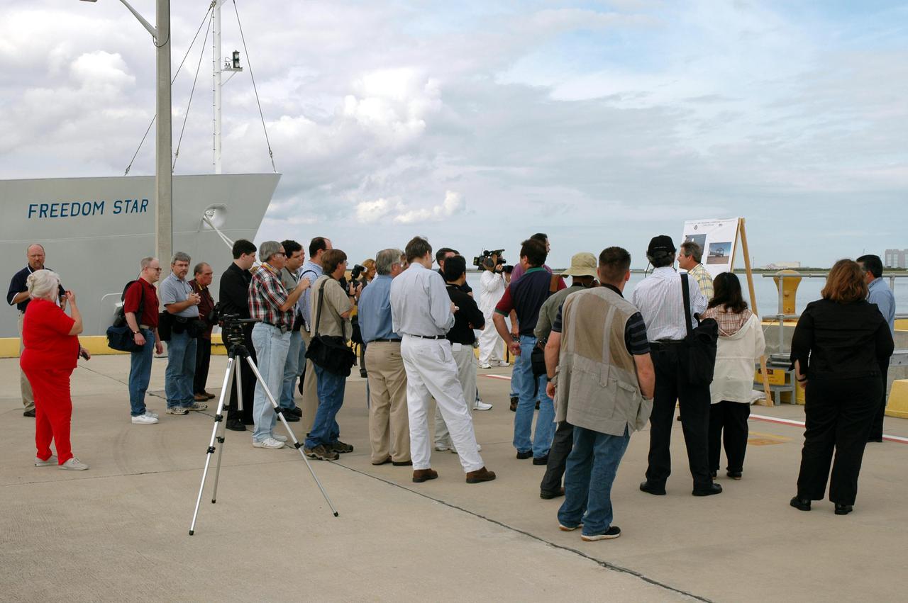
KENNEDY SPACE CENTER, FLA. - On the deck of the Freedom Star, one of the Solid Rocket Booster (SRB) retrieval ships, the media learn about retrieval operations. The stop was part of a day-long event that featured the movement of the first SRB segments to the Vehicle Assembly Building for stacking for Return to Flight mission STS-114. Two SRBs support the liftoff of the Space Shuttle on a launch. The twin 149-foot tall, 12-foot diameter SRBs provide the main propulsion system during launch to place the orbiters in the proper orbit around the Earth. They operate parallel with the Space Shuttle main engines for the first two minutes of flight and jettison away from the orbiter, with help from the Booster Separation Motors, about 26.3 nautical miles above the Earth’s surface.
KENNEDY SPACE CENTER, FLA. - The media tour the Solid Rocket Booster (SRB) Assembly and Refurbishment Facility where SRB segments are refurbished. In the background can be seen the frustum and nose cap of an SRB. The media event featured the movement of the first SRB segments to the Vehicle Assembly Building for stacking for Return to Flight mission STS-114. Two SRBs support the liftoff of the Space Shuttle on a launch. The twin 149-foot tall, 12-foot diameter SRBs provide the main propulsion system during launch to place the orbiters in the proper orbit around the Earth. They operate parallel with the Space Shuttle main engines for the first two minutes of flight and jettison away from the orbiter, with help from the Booster Separation Motors, about 26.3 nautical miles above the Earth’s surface.

KENNEDY SPACE CENTER, FLA. - The aft skirt and lower segment of the Solid Rocket Booster (SRB) being prepared for Return to Flight on mission STS-114 are being transported from the Rotation Processing and Surge Facility to the Vehicle Assembly Building. Other segments will be moved to the VAB later for stacking. Two SRBs support the liftoff of the Space Shuttle on a launch. The twin 149-foot tall, 12-foot diameter SRBs provide the main propulsion system during launch to place the 180,000-pound orbiters in the proper orbit around the Earth. They operate parallel with the Space Shuttle main engines for the first two minutes of flight and jettison away from the orbiter with help from the Booster Separation Motors, about 26.3 nautical miles above the Earth’s surface.

KENNEDY SPACE CENTER, FLA. - This view from above shows the place where the Solid Rocket Booster (SRB) for the Return to Flight mission STS-114 will be stacked. The aft skirt and lower segment were transported to the VAB Nov. 22. In the background are media who are reporting on this significant milestone. Two SRBs support the liftoff of the Space Shuttle on a launch. The twin 149-foot tall, 12-foot diameter SRBs provide the main propulsion system during launch to place the 180,000-pound orbiters in the proper orbit around the Earth. They operate parallel with the Space Shuttle main engines for the first two minutes of flight and jettison away from the orbiter with help from the Booster Separation Motors, about 26.3 nautical miles above the Earth’s surface.