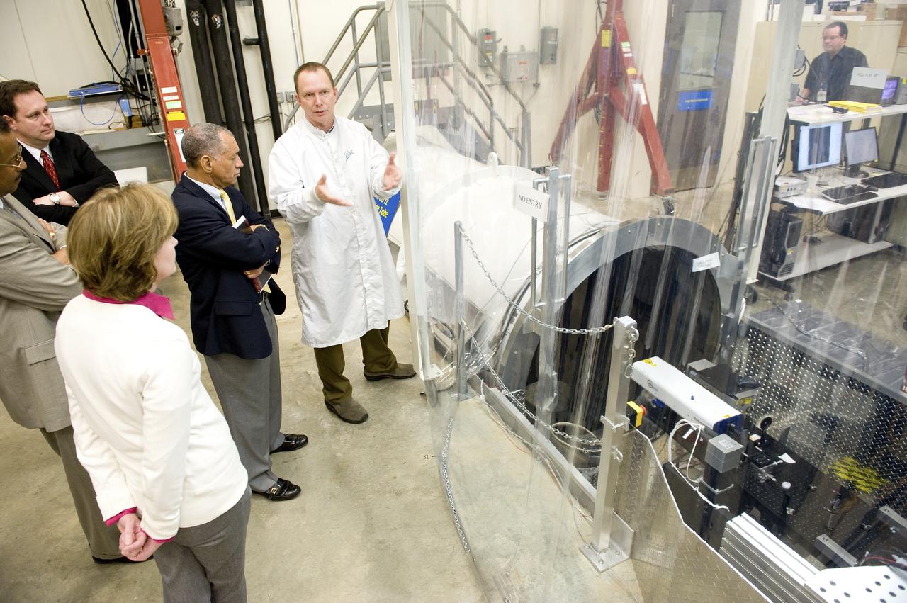
NASA ADMINISTRATOR CHARLES BOLDEN LOOKS ON AS BALL AEROSPACE TECHNOLOGIES CORPORATION PRINCIPLE OPTICAL ENGINEER DAVE CHANEY EXPLAINS HOW THE JAMES WEBB SPACE TELESCOPE MIRROR SEGMENTS ARE TESTED IN MARSHALL'S X-RAY AND CRYOGENIC FACILITY. PICTURED FROM LEFT: HELEN COLE, WEBB TELESCOPE ACTIVITIES PROJECT MANAGER AT MARSHALL; CHARLES SCALES, ASSOCIATE DEPUTY ADMINISTRATOR: ROBERT LIGHTFOOT, CENTER DIRECTOR; CHARLES BOLDEN, NASA ADMINISTRATOR; DAVE CHANEY, BALL OPTICAL ENGINEER.
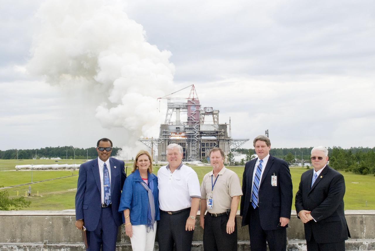
Steam billows from an RS-68 rocket engine test at the B Test Stand at Stennis Space Center on June 2. The test was viewed by Mississippi Gov. Haley Barbour (third from left) and his wife, Marsha, who spent the afternoon at the NASA rocket engine testing center. The governor was joined at the RS-68 test by (l to r) Charles Scales, NASA associate deputy administrator; Jeffrey Wright, Pratt & Whitney Rocketdyne site director at Stennis; Gene Goldman, Stennis director; and Jack Forsythe, NASA assistant administrator for the Office of Security and Program Protection.
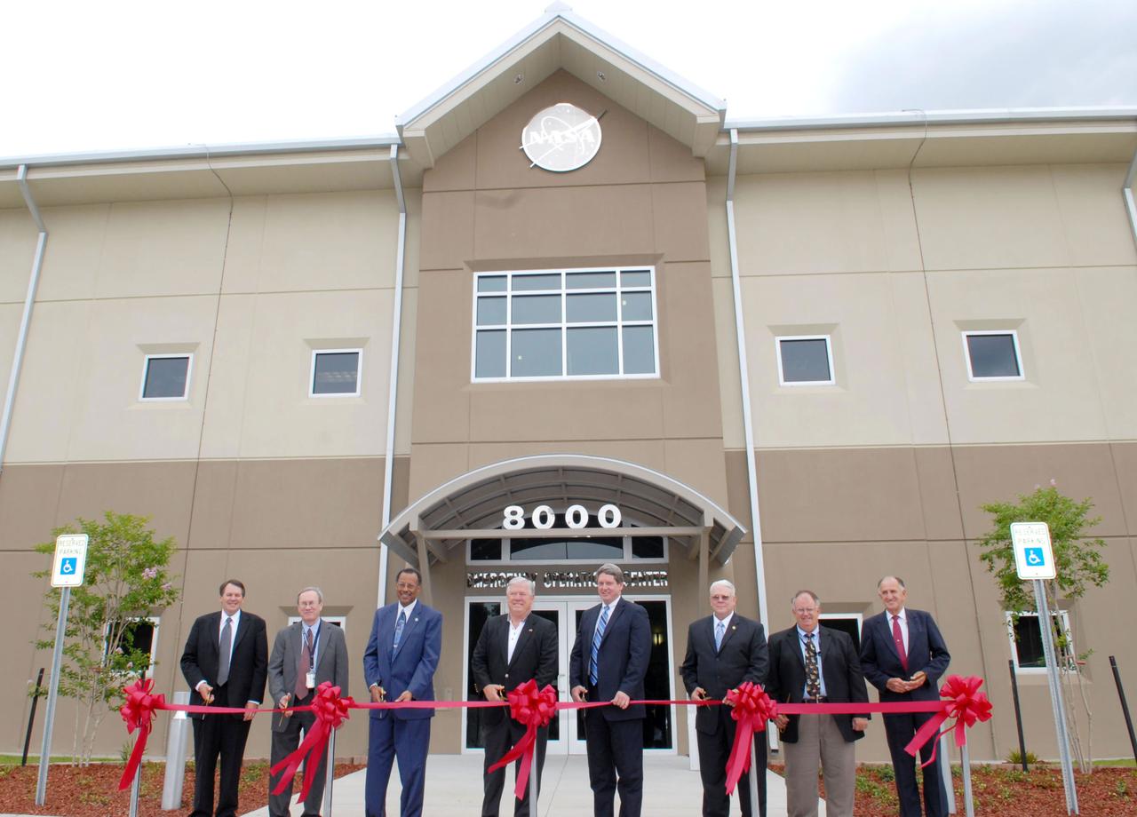
Center Director Gene Goldman and special guests celebrate the opening of the site's new Emergency Operations Center on June 2. Participants included (l t r): Steven Cooper, deputy director of the National Weather Service Southern Region; Tom Luedtke, NASA associate administrator for institutions and management; Charles Scales, NASA associate deputy administrator; Mississippi Gov. Haley Barbour; Gene Goldman, director of Stennis Space Center; Jack Forsythe, NASA assistant administrator for the Office of Security and Program Protection; Dr. Richard Williams, NASA chief health and medical officer; and Weldon Starks, president of Starks Contracting Company Inc. of Biloxi.
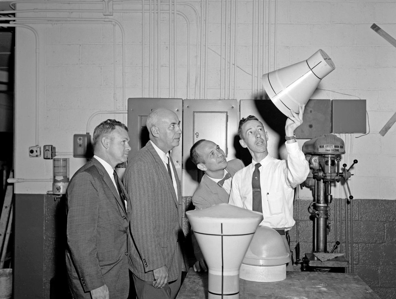
From left to right: Charles Donlan, deputy head, and Robert Gilruth, head of STG, look at a scale model of a Mercury space capsule.

CAPE CANAVERAL, Fla. -- During a Minority Student Education Forum, NASA's Associate Deputy Administrator Charles Scales talks to hundreds of fifth- through 12th-grade students. The forum focused on encouraging students to pursue careers in science, technology, engineering and mathematics, or STEM, by featuring some of NASA's greatest legends and trailblazers. NASA's Education Office sponsored the forum as part of the agency's 'Summer of Innovation' initiative and the federal 'Education to Innovate' campaign. Photo credit: NASA_Cory Huston
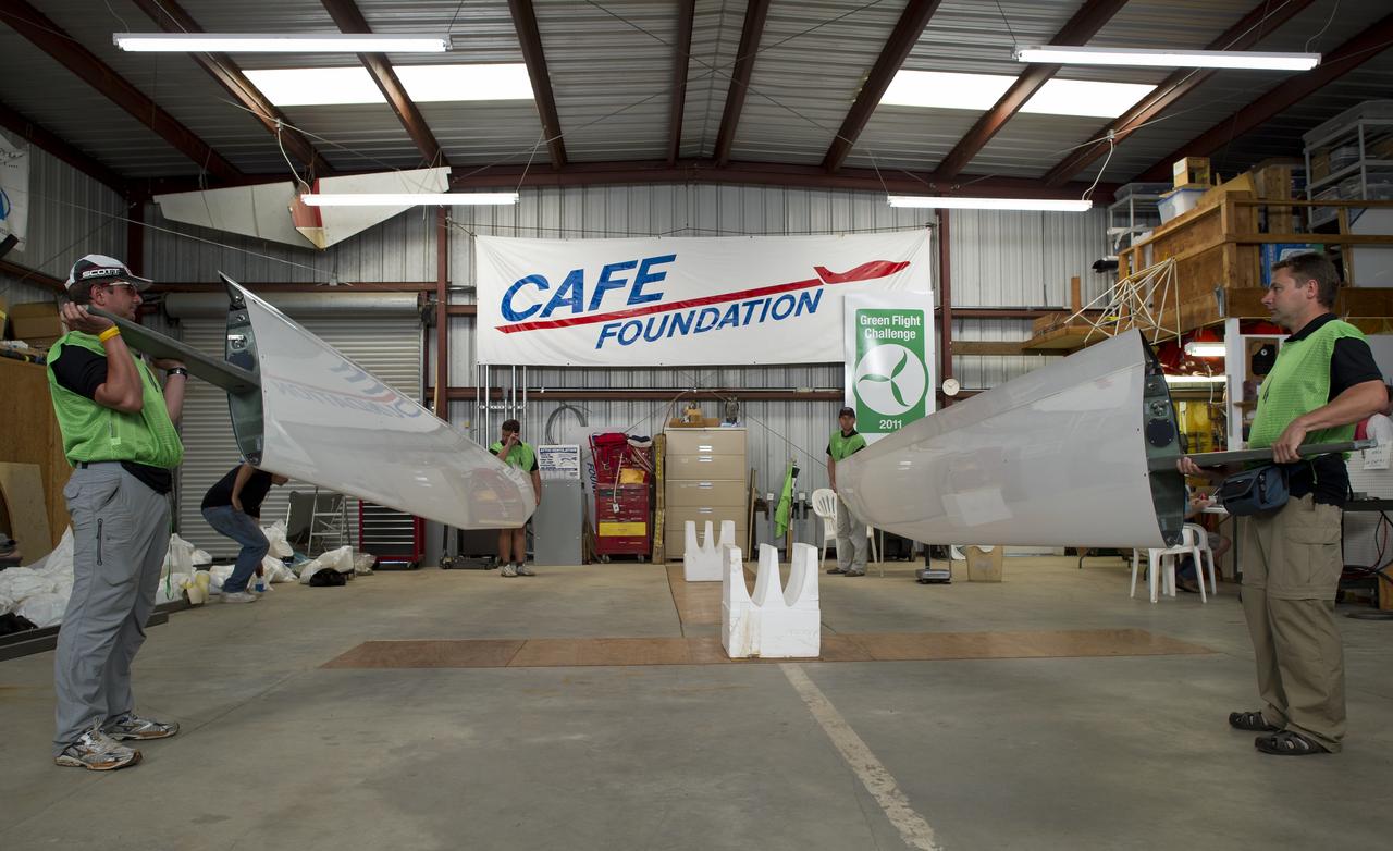
Team members of Pipistrel-USA prepare to have their Taurus G4 aircraft wings weighed using a scale built into the floor of the hangar during the 2011 Green Flight Challenge, sponsored by Google, at the Charles M. Schulz Sonoma County Airport in Santa Rosa, Calif. on Monday, Sept. 26, 2011. NASA and the Comparative Aircraft Flight Efficiency (CAFE) Foundation are having the challenge with the goal to advance technologies in fuel efficiency and reduced emissions with cleaner renewable fuels and electric aircraft. Photo Credit: (NASA/Bill Ingalls)
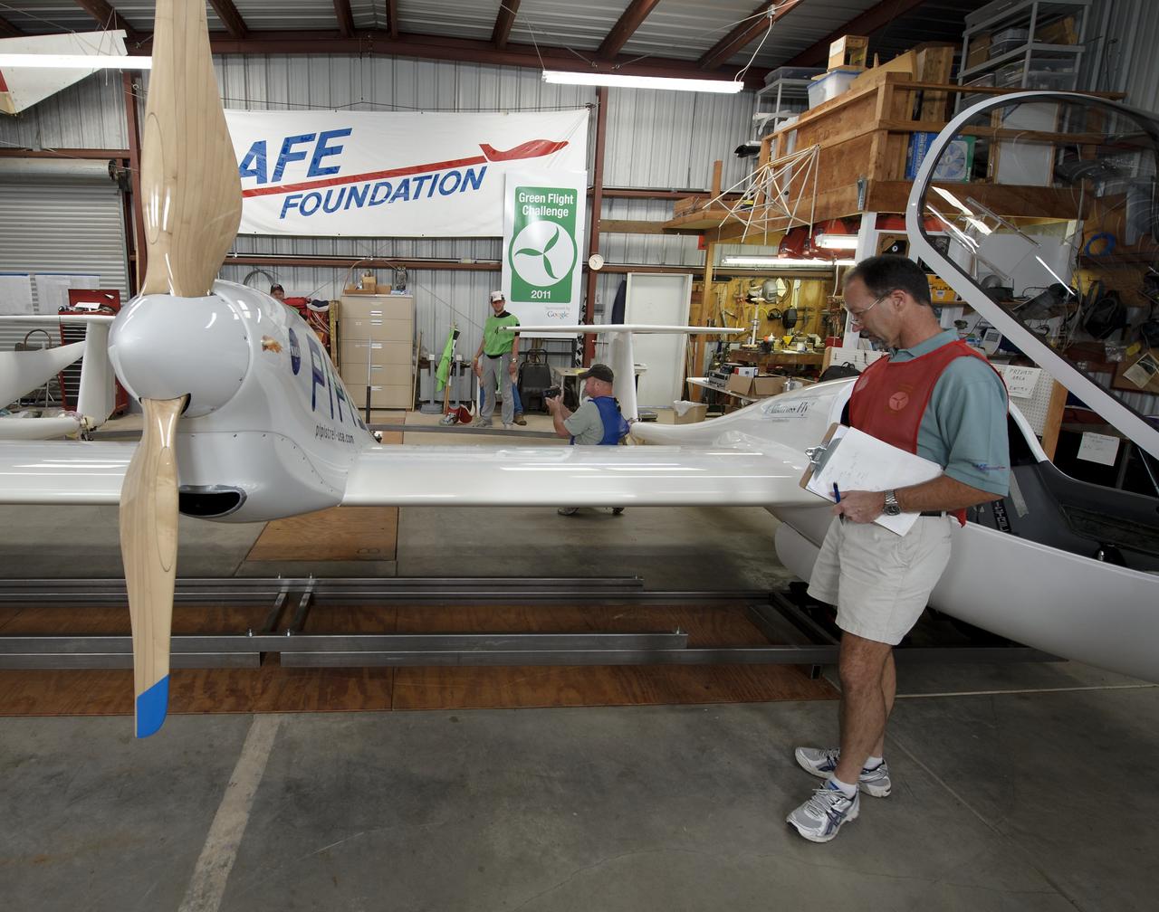
Wayne Cook, Weights Chief, inspects the Pipistrel-USA, Taurus G4 as it rest on a scale built into the floor of the hangar during the 2011 Green Flight Challenge, sponsored by Google, at the Charles M. Schulz Sonoma County Airport in Santa Rosa, Calif. on Monday, Sept. 26, 2011. NASA and the Comparative Aircraft Flight Efficiency (CAFE) Foundation are having the challenge with the goal to advance technologies in fuel efficiency and reduced emissions with cleaner renewable fuels and electric aircraft. Photo Credit: (NASA/Bill Ingalls)
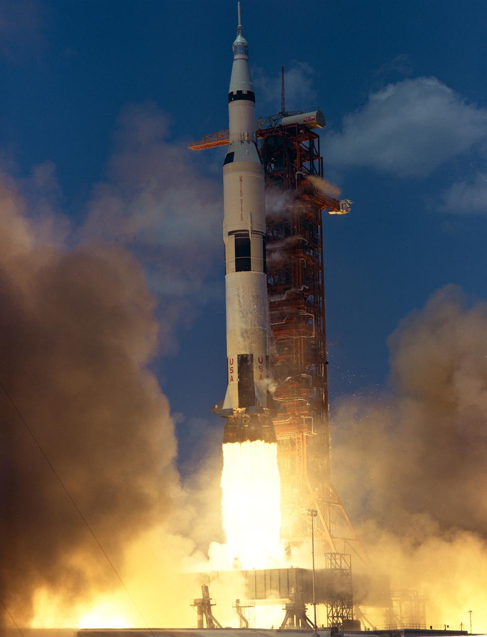
The sixth marned lunar landing mission, the Apollo 16 (SA-511), carrying three astronauts: Mission commander John W. Young, Command Module pilot Thomas K. Mattingly II, and Lunar Module pilot Charles M. Duke, lifted off on April 16, 1972. The Apollo 16 continued the broad-scale geological, geochemical, and geophysical mapping of the Moon's crust, begun by the Apollo 15, from lunar orbit. This mission marked the first use of the Moon as an astronomical observatory by using the ultraviolet camera/spectrograph. It photographed ultraviolet light emitted by Earth and other celestial objects. The Lunar Roving Vehicle was also used. The mission ended on April 27, 1972.
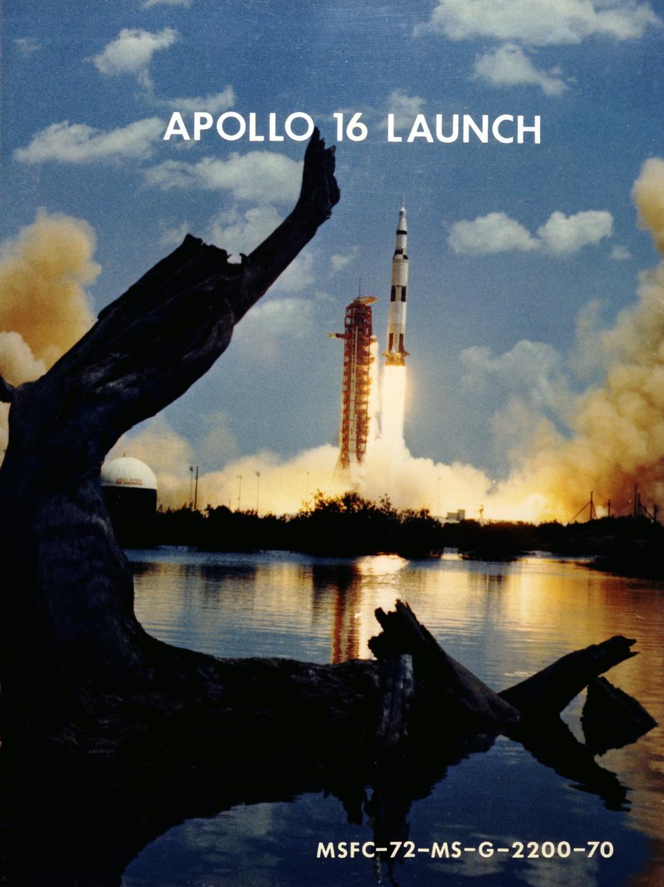
The sixth manned lunar landing mission, the Apollo 16 (SA-511), carrying three astronauts: Mission Commander John W. Young, Command Module pilot Thomas K. Mattingly II, and Lunar Module pilot Charles M. Duke, lifted off on April 16, 1972. The Apollo 16 mission continued the broad-scale geological, geochemical, and geophysical mapping of the Moon’s crust, begun by the Apollo 15, from lunar orbit. This mission marked the first use of the Moon as an astronomical observatory by using the ultraviolet camera/spectrograph which photographed ultraviolet light emitted by Earth and other celestial objects. The Lunar Roving Vehicle, developed by the Marshall Space Flight Center, was also used. The mission ended on April 27, 1972.
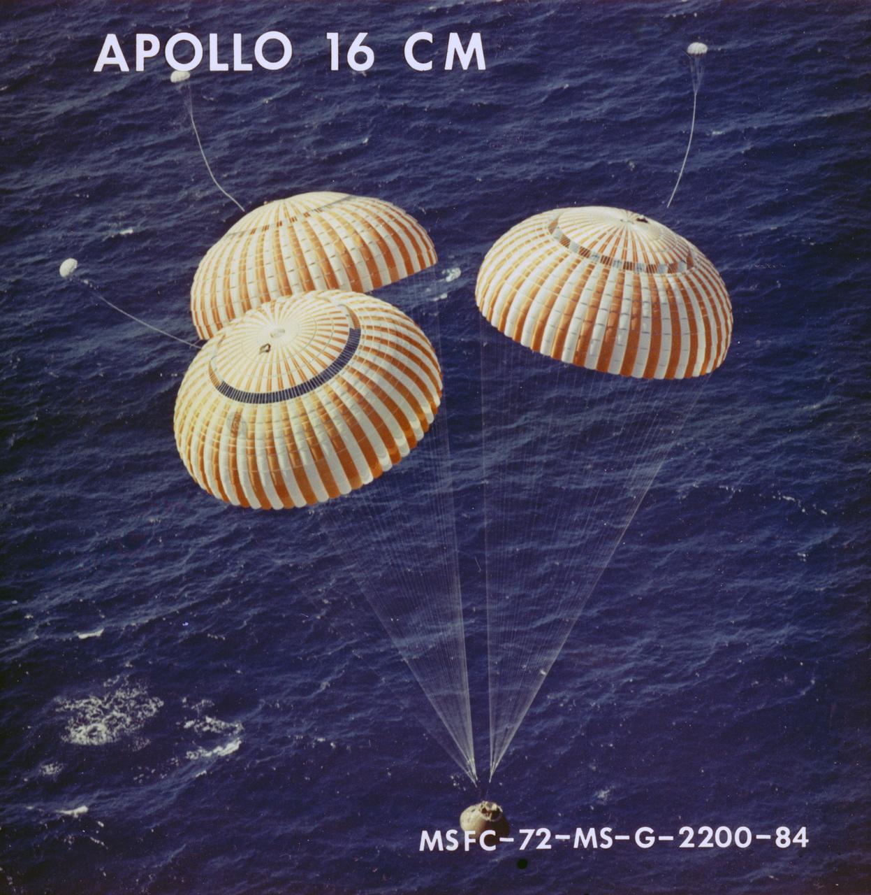
The Apollo 16 Command Module splashed down in the Pacific Ocean on April 27, 1972 after an 11-day moon exploration mission. The sixth manned lunar landing mission, the Apollo 16 (SA-511), carrying three astronauts: Mission Commander John W. Young, Command Module pilot Thomas K. Mattingly II, and Lunar Module pilot Charles M. Duke, lifted off on April 16, 1972. The Apollo 16 continued the broad-scale geological, geochemical, and geophysical mapping of the Moon’s crust, begun by the Apollo 15, from lunar orbit. This mission marked the first use of the Moon as an astronomical observatory by using the ultraviolet camera/spectrograph which photographed ultraviolet light emitted by Earth and other celestial objects. The Lunar Roving Vehicle, developed by the Marshall Space Flight Center, was also used.
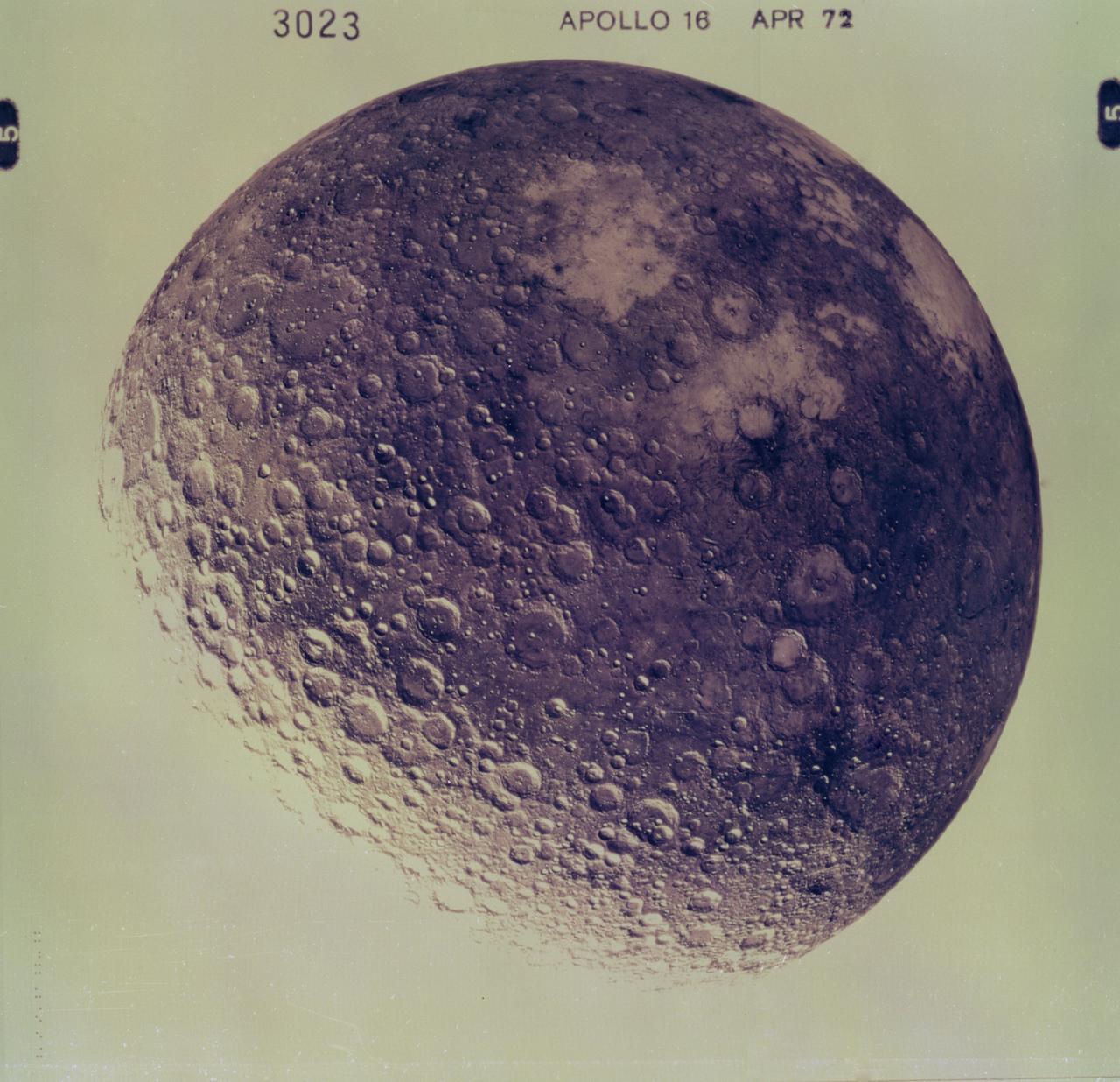
This view of the back side of the Moon was captured by the Apollo 16 mission crew. The sixth manned lunar landing mission, the Apollo 16 (SA-511), carrying three astronauts: Mission Commander John W. Young, Command Module pilot Thomas K. Mattingly II, and Lunar Module pilot Charles M. Duke, lifted off on April 16, 1972. The Apollo 16 continued the broad-scale geological, geochemical, and geophysical mapping of the Moon’s crust, begun by the Apollo 15, from lunar orbit. This mission marked the first use of the Moon as an astronomical observatory by using the ultraviolet camera/spectrograph which photographed ultraviolet light emitted by Earth and other celestial objects. The Lunar Roving Vehicle, developed by the Marshall Space Flight Center, was also used. The mission ended on April 27, 1972.
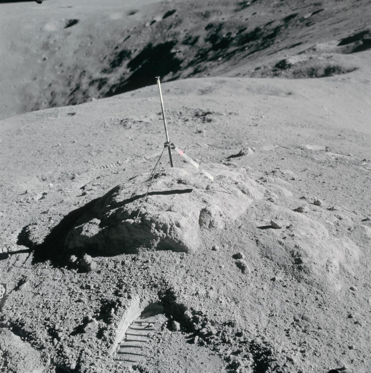
AS16-114-18412 (16-27 April 1972) --- The gnomon and color patch, one of the Apollo Lunar Hand Tools (ALHT), is deployed atop a lunar rock, in this photograph taken by one of the Apollo 16 astronauts during their lunar surface extravehicular activity (EVA) at the Descartes landing site. The gnomon is used as a photographic reference to establish local vertical sun angle, scale, and lunar color. The color patch, mounted on one of the legs of the tripod, provides a larger target for accurately determining colors in color photography. A portion of Flag Crater can be seen in the background. While astronauts John W. Young, commander; and Charles M. Duke Jr., lunar module pilot; descended in the Apollo 16 Lunar Module (LM) "Orion" to explore the Descartes highlands landing site on the moon, astronaut Thomas K. Mattingly II, command module pilot, remained with the Command and Service Modules (CSM) "Casper" in lunar orbit.

CAPE CANAVERAL, Fla. -- At NASA's Kennedy Space Center in Florida, Luz Marina Calle, left, shows Rep. Suzanne Kosmas, NASA Associate Deputy Administrator Charles Scales and Commerce Secretary Gary Locke the types of experiments taking place in the Space Life Sciences Lab. Calle's research focuses on corrosion prevention. As part of Locke's visit to Kennedy a meeting also was held with about a dozen workers expected to lose their jobs with the retirement of the Space Shuttle Program to discuss what the Commerce Department, NASA and the White House are doing to improve the local economy as the program winds down. NASA Administrator Charlie Bolden and Locke co-chair the White House’s Task Force on Space Industry Workforce and Economic Development, which was formed in May and is expected to provide a report to President Obama this month. Photo credit: NASA_Kim Shiflett
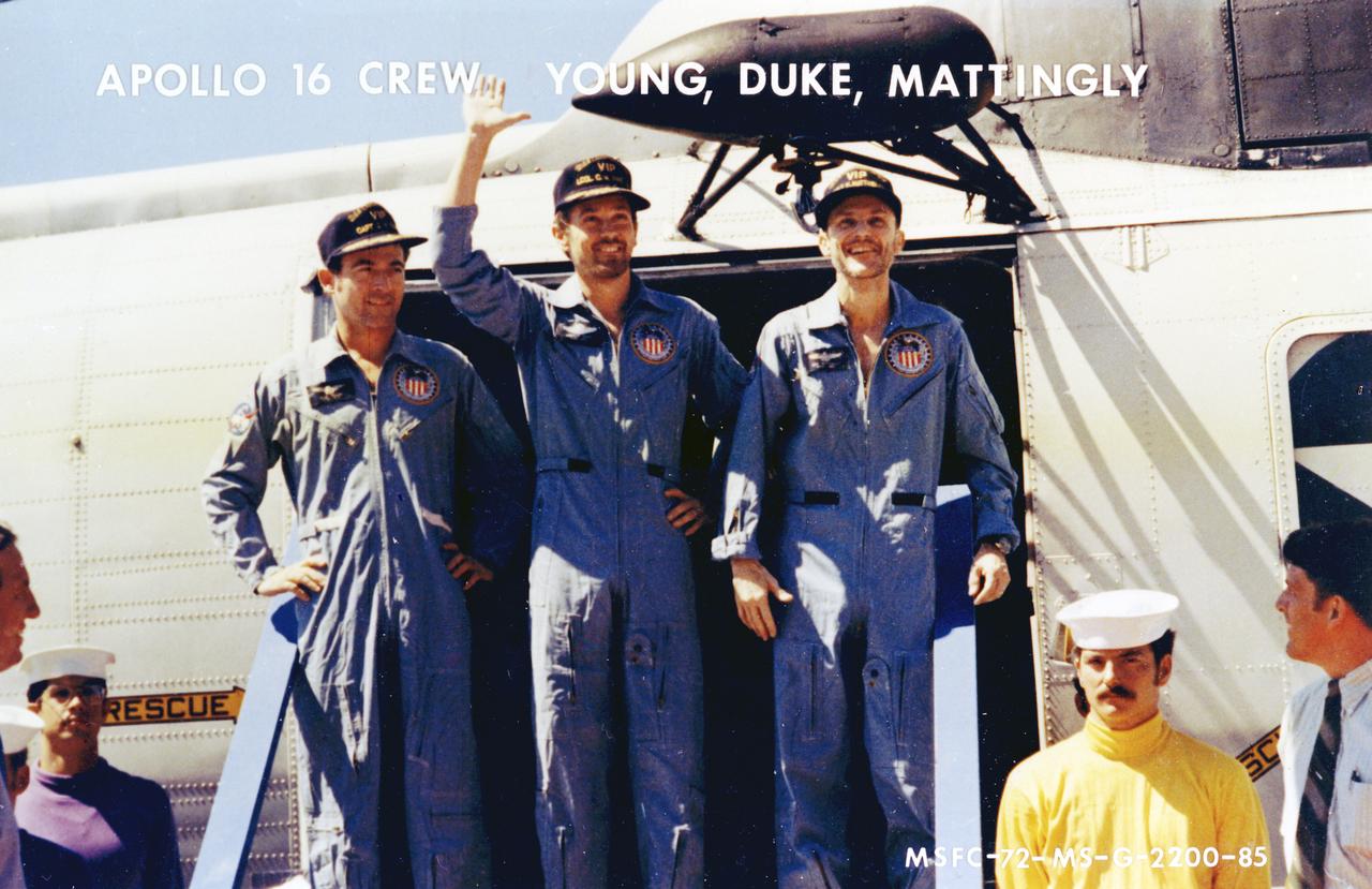
The Apollo 16 Command Module splashed down in the Pacific Ocean on April 27, 1972 after an 11-day moon exploration mission. The 3-man crew is shown here aboard the rescue ship, USS Horton. From left to right are: Mission Commander John W. Young, Lunar Module pilot Charles M. Duke, and Command Module pilot Thomas K. Mattingly II. The sixth manned lunar landing mission, the Apollo 16 (SA-511) lifted off on April 16, 1972. The Apollo 16 mission continued the broad-scale geological, geochemical, and geophysical mapping of the Moon’s crust, begun by the Apollo 15, from lunar orbit. This mission marked the first use of the Moon as an astronomical observatory by using the ultraviolet camera/spectrograph which photographed ultraviolet light emitted by Earth and other celestial objects. The Lunar Roving Vehicle, developed by the Marshall Space Flight Center, was also used.
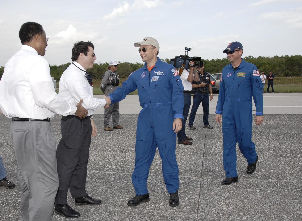
CAPE CANAVERAL, Fla. – STS-119 Commander Lee Archambault shakes hands with NASA Acting Administrator Chris Scolese as NASA Deputy Associate Administrator Charles Scales, left, also prepares to welcome him home. Pilot Tony Antonelli approaches the group, at right. Space shuttle Discovery’s landing completed the 13-day, 5.3-million mile journey of the STS-119 mission to the International Space Station. Main gear touchdown was at 3:13:17 p.m. EDT. Nose gear touchdown was at 3:13:40 p.m. and wheels stop was at 3:14:45 p.m. Discovery delivered the final pair of large power-generating solar array wings and the S6 truss segment. The mission was the 28th flight to the station, the 36th flight of Discovery and the 125th in the Space Shuttle Program, as well as the 70th landing at Kennedy. Photo credit: NASA/Kim Shiflett
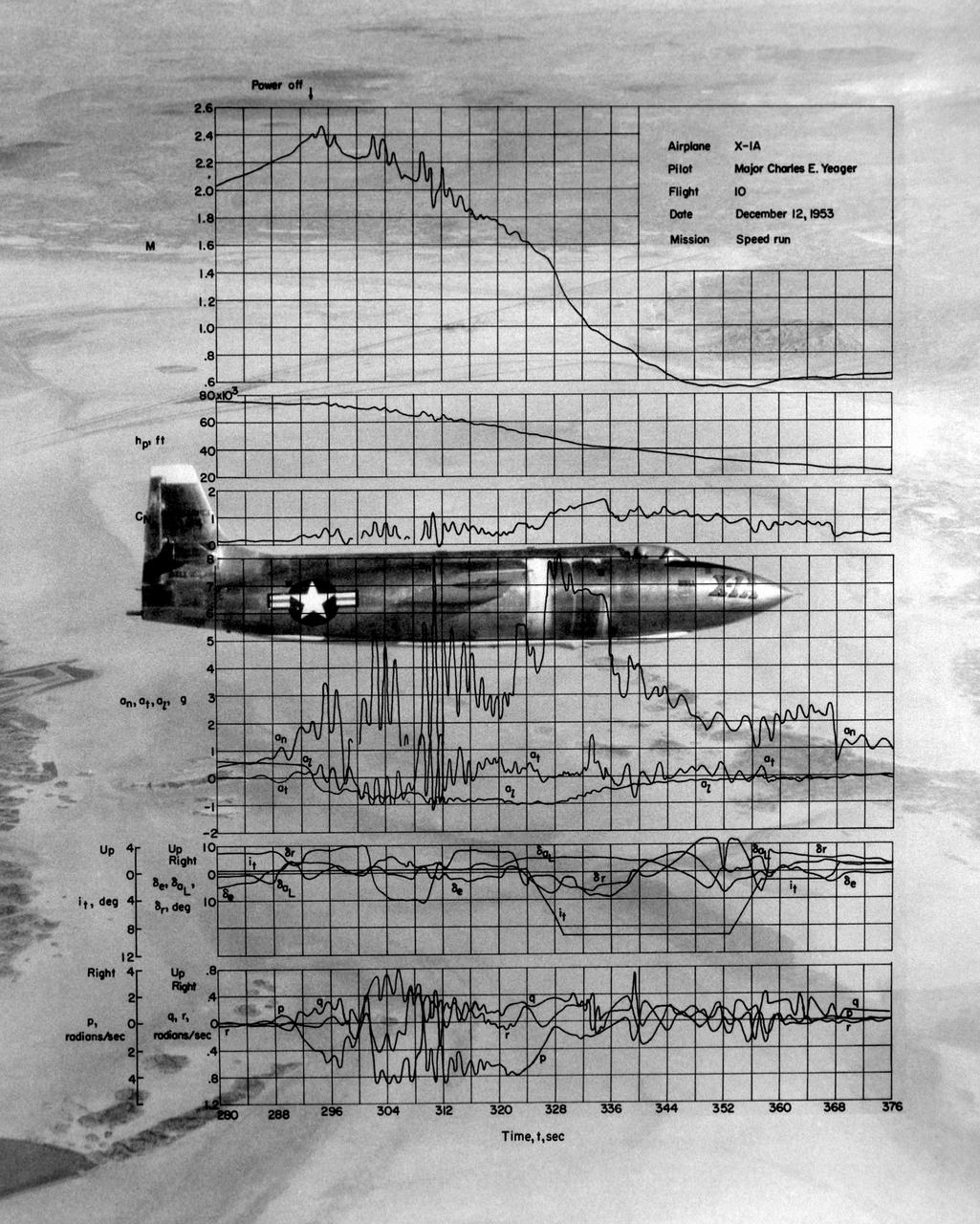
This photo of the X-1A includes graphs of the flight data from Maj. Charles E. Yeager's Mach 2.44 flight on December 12, 1953. (This was only a few days short of the 50th anniversary of the Wright brothers' first powered flight.) After reaching Mach 2.44, then the highest speed ever reached by a piloted aircraft, the X-1A tumbled completely out of control. The motions were so violent that Yeager cracked the plastic canopy with his helmet. He finally recovered from a inverted spin and landed on Rogers Dry Lakebed. Among the data shown are Mach number and altitude (the two top graphs). The speed and altitude changes due to the tumble are visible as jagged lines. The third graph from the bottom shows the G-forces on the airplane. During the tumble, these twice reached 8 Gs or 8 times the normal pull of gravity at sea level. (At these G forces, a 200-pound human would, in effect, weigh 1,600 pounds if a scale were placed under him in the direction of the force vector.) Producing these graphs was a slow, difficult process. The raw data from on-board instrumentation recorded on oscillograph film. Human computers then reduced the data and recorded it on data sheets, correcting for such factors as temperature and instrument errors. They used adding machines or slide rules for their calculations, pocket calculators being 20 years in the future.
![Astronaut Charles Conrad at the controls of the Visual Docking Simulator. From A.W. Vogeley, "Piloted Space-Flight Simulation at Langley Research Center," paper presented at the American Society of Mechanical Engineers 1966 Winter Meeting, New York, NY, November 27-December 1, 1966. "This facility was [later known as the Visual-Optical Simulator.] It presents to the pilot an out-the-window view of his target in correct 6 degrees of freedom motion. The scene is obtained by a television camera pick-up viewing a small-scale gimbaled model of the target." "For docking studies, the docking target picture was projected onto the surface of a 20-foot-diameter sphere and the pilot could, effectively, maneuver into contract. this facility was used in a comparison study with the Rendezvous Docking Simulator - one of the few comparison experiments in which conditions were carefully controlled and a reasonable sample of pilots used. All pilots preferred the more realistic RDS visual scene. The pilots generally liked the RDS angular motion cues although some objected to the false gravity cues that these motions introduced. Training time was shorter on the RDS, but final performance on both simulators was essentially equal. " "For station-keeping studies, since close approach is not required, the target was presented to the pilot through a virtual-image system which projects his view to infinity, providing a more realistic effect. In addition to the target, the system also projects a star and horizon background. "](https://images-assets.nasa.gov/image/LRC-1963-B701_P-09519/LRC-1963-B701_P-09519~medium.jpg)
Astronaut Charles Conrad at the controls of the Visual Docking Simulator. From A.W. Vogeley, "Piloted Space-Flight Simulation at Langley Research Center," paper presented at the American Society of Mechanical Engineers 1966 Winter Meeting, New York, NY, November 27-December 1, 1966. "This facility was [later known as the Visual-Optical Simulator.] It presents to the pilot an out-the-window view of his target in correct 6 degrees of freedom motion. The scene is obtained by a television camera pick-up viewing a small-scale gimbaled model of the target." "For docking studies, the docking target picture was projected onto the surface of a 20-foot-diameter sphere and the pilot could, effectively, maneuver into contract. this facility was used in a comparison study with the Rendezvous Docking Simulator - one of the few comparison experiments in which conditions were carefully controlled and a reasonable sample of pilots used. All pilots preferred the more realistic RDS visual scene. The pilots generally liked the RDS angular motion cues although some objected to the false gravity cues that these motions introduced. Training time was shorter on the RDS, but final performance on both simulators was essentially equal. " "For station-keeping studies, since close approach is not required, the target was presented to the pilot through a virtual-image system which projects his view to infinity, providing a more realistic effect. In addition to the target, the system also projects a star and horizon background. "
![Astronauts Charles Conrad (left) and John W. Young (right) at the controls of the Visual Docking Simulator. From A.W. Vogeley, "Piloted Space-Flight Simulation at Langley Research Center," Paper presented at the American Society of Mechanical Engineers 1966 Winter Meeting, New York, NY, November 27-December 1, 1966. "This facility was [later known as the Visual-Optical Simulator.] It presents to the pilot an out-the-window view of his target in correct 6 degrees of freedom motion. The scene is obtained by a television camera pick-up viewing a small-scale gimbaled model of the target." "For docking studies, the docking target picture was projected onto the surface of a 20-foot-diameter sphere and the pilot could, effectively, maneuver into contract. this facility was used in a comparison study with the Rendezvous Docking Simulator - one of the few comparison experiments in which conditions were carefully controlled and a reasonable sample of pilots used. All pilots preferred the more realistic RDS visual scene. The pilots generally liked the RDS angular motion cues although some objected to the false gravity cues that these motions introduced. Training time was shorter on the RDS, but final performance on both simulators was essentially equal. " "For station-keeping studies, since close approach is not required, the target was presented to the pilot through a virtual-image system which projects his view to infinity, providing a more realistic effect. In addition to the target, the system also projects a star and horizon background. "](https://images-assets.nasa.gov/image/LRC-1963-B701_P-09520/LRC-1963-B701_P-09520~medium.jpg)
Astronauts Charles Conrad (left) and John W. Young (right) at the controls of the Visual Docking Simulator. From A.W. Vogeley, "Piloted Space-Flight Simulation at Langley Research Center," Paper presented at the American Society of Mechanical Engineers 1966 Winter Meeting, New York, NY, November 27-December 1, 1966. "This facility was [later known as the Visual-Optical Simulator.] It presents to the pilot an out-the-window view of his target in correct 6 degrees of freedom motion. The scene is obtained by a television camera pick-up viewing a small-scale gimbaled model of the target." "For docking studies, the docking target picture was projected onto the surface of a 20-foot-diameter sphere and the pilot could, effectively, maneuver into contract. this facility was used in a comparison study with the Rendezvous Docking Simulator - one of the few comparison experiments in which conditions were carefully controlled and a reasonable sample of pilots used. All pilots preferred the more realistic RDS visual scene. The pilots generally liked the RDS angular motion cues although some objected to the false gravity cues that these motions introduced. Training time was shorter on the RDS, but final performance on both simulators was essentially equal. " "For station-keeping studies, since close approach is not required, the target was presented to the pilot through a virtual-image system which projects his view to infinity, providing a more realistic effect. In addition to the target, the system also projects a star and horizon background. "