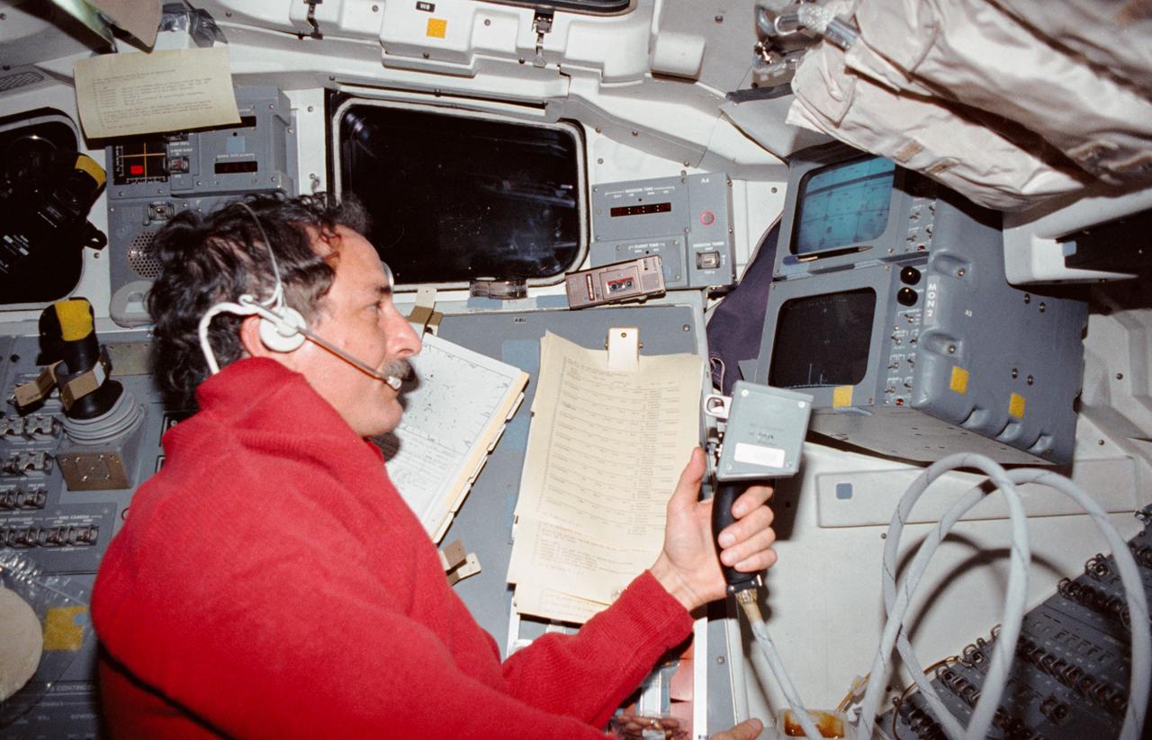
STS035-10-011 (2-10 Dec 1990) --- STS-35 Mission Specialist (MS) Robert A.R. Parker operates Astronomy Laboratory 1 (ASTRO-1) manual pointing controller (MPC) on the aft flight deck of Columbia, Orbiter Vehicle (OV) 102. Parker monitors a closed circuit television (CCTV) screen at the payload station as he uses the MPC to send data collection instructions to the ASTRO-1 instrument pointing system (IPS).
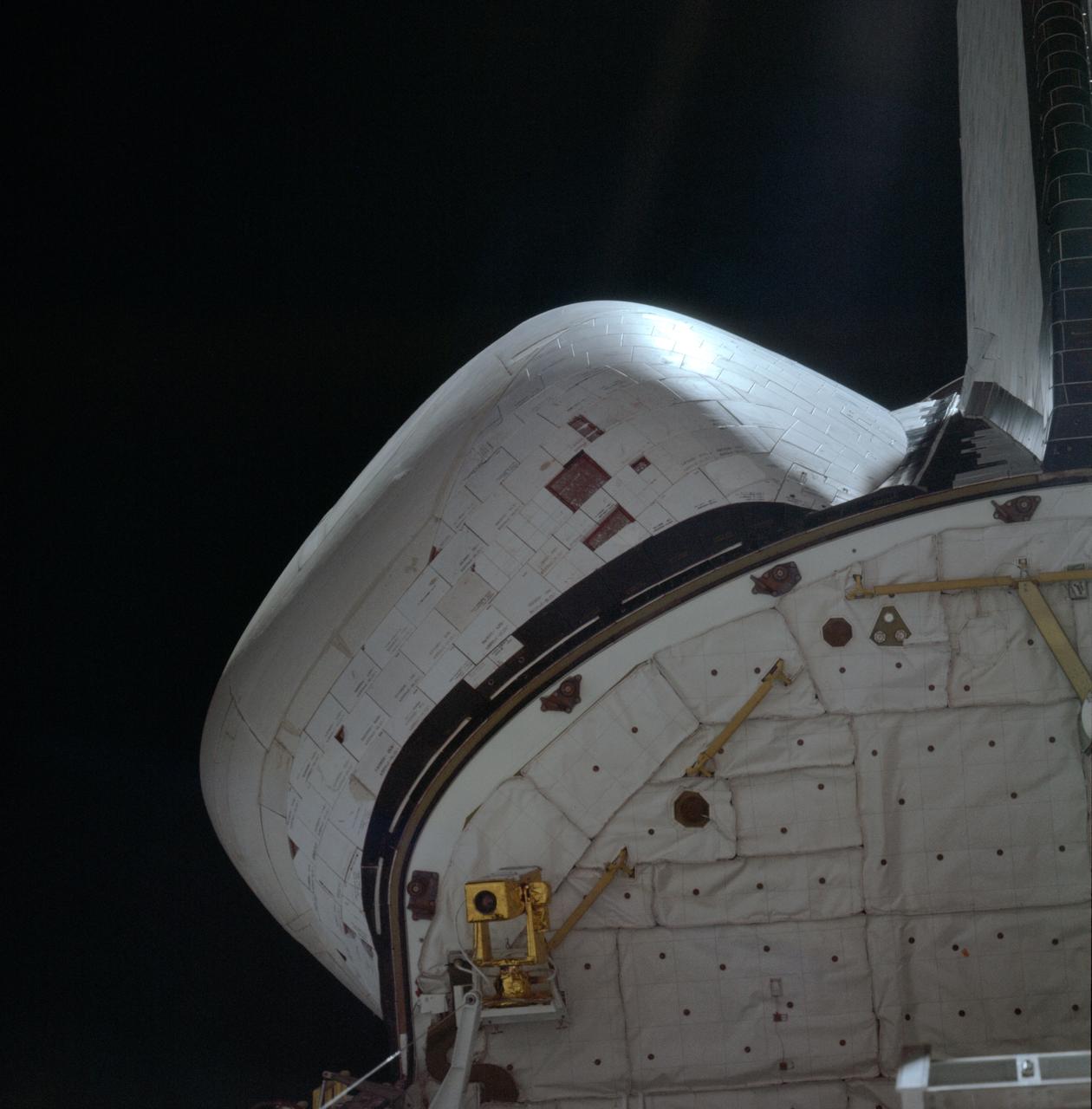
STS001-08-289 (12-14 April 1981) --- A 250mm Hasselblad view of the left OMS pod and missing tiles. Photo credit: NASA
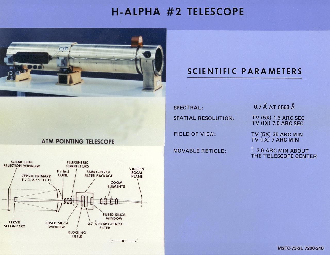
This chart describes the Hydrogen-Alpha (H-Alpha) #2 Telescope, one of eight major solar study facilities on the Skylab Apollo Telescope Mount (ATM). There were two H-Alpha telescopes on the ATM that were used primarily to point the ATM and keep a continuous photographic record during solar observation periods. Both telescopes gave the Skylab astronauts a real-time picture of the Sun in the red light of the H-Alpha spectrum through a closed-circuit television. The H-Alpha #1 telescope provided simultaneous photographic and ultraviolet (UV) pictures, while the #2 telescope operated only in the TV mode. The Marshall Space Flight Center was responsible for development of the H-Alpha Telescopes.
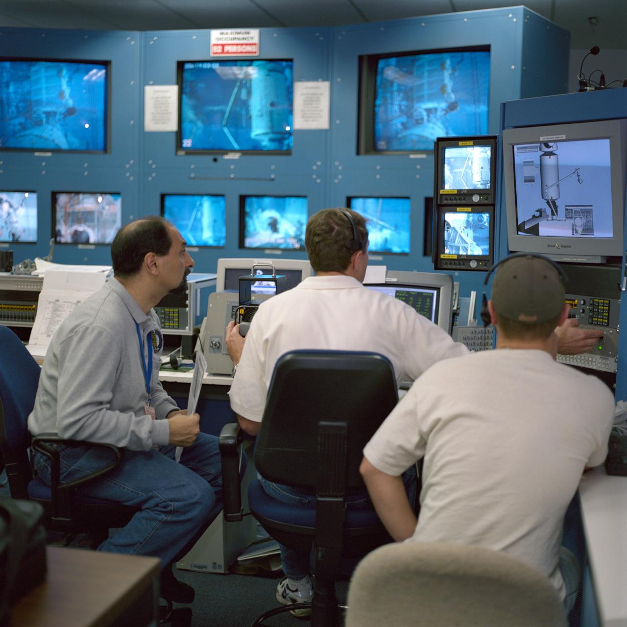
JSC2000-07406 (1 December 2000) --- Astronaut Umberto Guidoni (left), STS-100 mission specialist representing the European Space Agency (ESA), views a closed-circuit televising of an underwater space walk simulation performed by two crew mates. The simulation of the scheduled spring 2001 space walk took place at the Neutral Buoyancy Laboratory (NBL) at the Sonny Carter Training Facility. Astronaut Jeffrey S. Ashby, pilot, is at center. Astronauts Scott E. Parazynski of the NASA-Johnson Space Center and Chris A. Hadfield of the Canadian Space Agency (CSA), both mission specialists and both equipped with training versions of the extravehicular mobility unit (EMU) space suits, were in the water at the time.
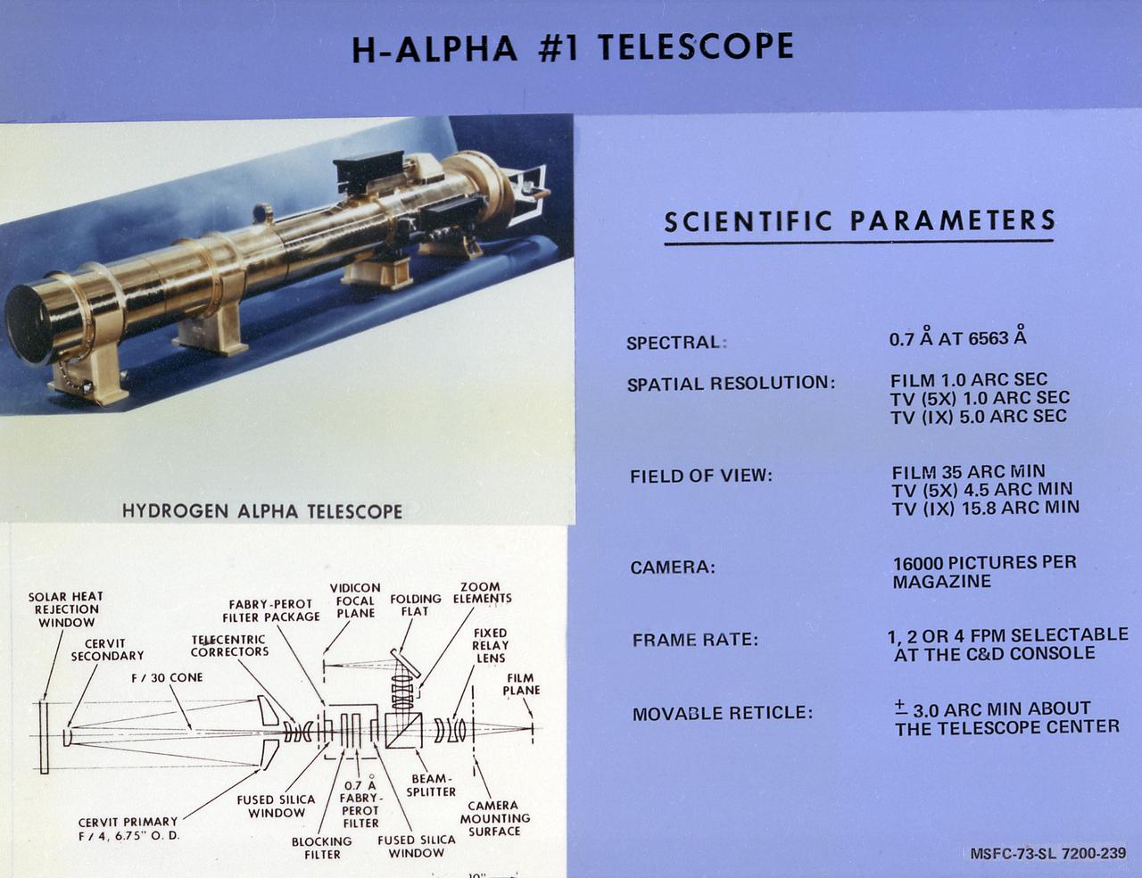
This chart describes the Hydrogen-Alpha (H-Alpha) #1 Telescope, one of eight major solar study facilities on the Skylab Apollo Telescope Mount (ATM). There were two H-Alpha telescopes on the ATM that were used primarily to point the ATM and keep a continuous photographic record during the solar observation periods. Both telescopes gave the Skylab astronauts a real-time picture of the Sun in the red light of the H-Alpha spectrum through a closed-circuit television. The H-Alpha #1 Telescope provided simultaneous photographic and ultraviolet (UV) pictures, while the #2 Telescope operated only in the TV mode. The Marshall Space Flight Center was responsible for development of the H-Alpha Telescopes.
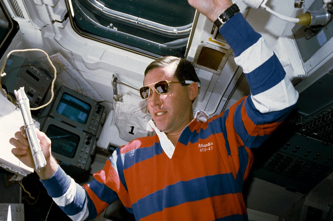
STS043-04-032 (11 Aug 1991) --- STS-43 Pilot Michael A. Baker, wearing sunglasses, reviews a checklist on the aft flight deck of Atlantis, Orbiter Vehicle (OV) 104. He is monitoring data associated with the Space Station Heat Pipe Advanced Radiator Element II (SHARE-II) located in OV-104's payload bay (PLB) from his position in front of the aft flight deck viewing windows. Behind Baker are the closed circuit television (CCTV) monitors and above his head is overhead window W8.
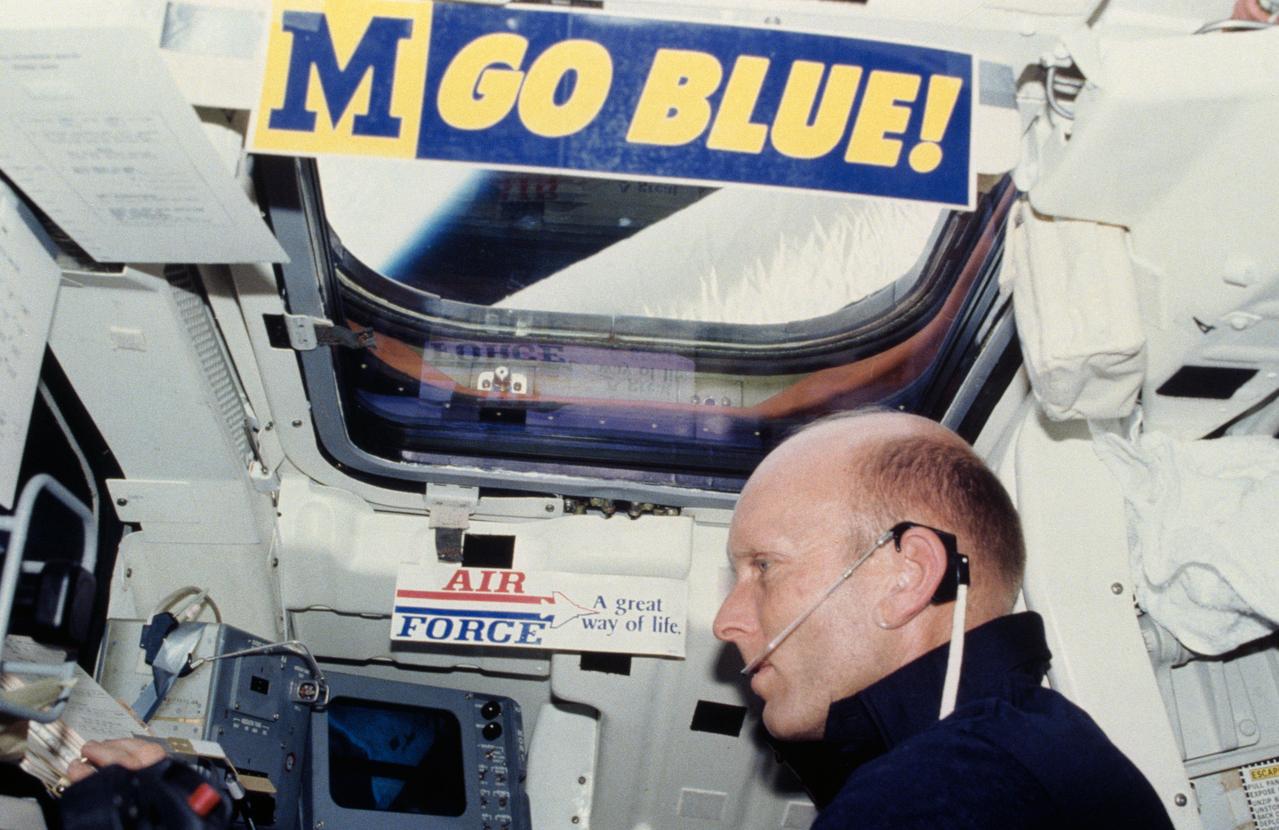
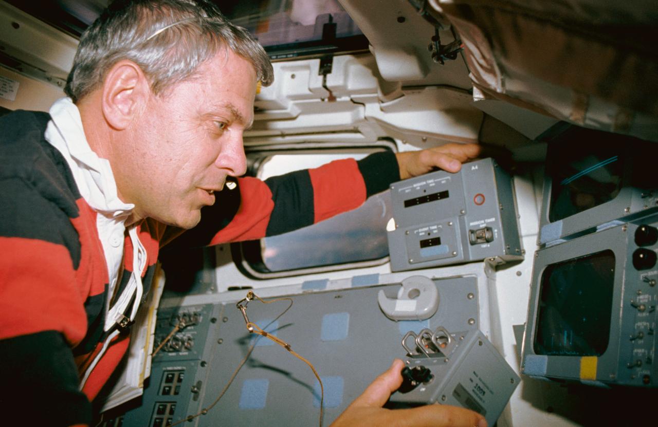
S82-28906 (27 March 1982) --- Astronaut C. Gordon Fullerton, STS-3 pilot, mans the right hand aft station of the flight deck on the Earth-orbiting Columbia. The photograph was taken with a 35mm camera by astronaut Jack R. Lousma, crew commander. The "Go Blue" sticker is a University of Michigan memento of Lousma, and the Air Force sign was put up by Fullerton, a USAF colonel. Lousma, a USMC colonel, received his BS degree in aeronautical engineering in 1959 from UM. One of two aft windows for cargo bay viewing and one of two ceiling windows are visible in the photo. Fullerton and Lousma watched the activity of the remote manipulator system (RMS) arm out the lower window and they took a number of photos of Earth from the upper window. Photo credit: NASA
STS035-12-015 (2-11 Dec 1990) --- Astronaut Jeffrey A. Hoffman, STS 35 mission specialist, uses a manual pointing controller (MPC) for the Astro-1 mission's Instrument Pointing System (IPS). By using the MPC, Hoffman and other crewmembers on Columbia's aft flight deck, were able to command the IPS, located in the cargo bay, to record astronomical data. Hoffman is serving the "Blue" shift which complemented the currently sleeping "Red" shift of crewmembers as the mission collected scientific data on a 24-hour basis. The scene was photographed with a 35mm camera.

Project LOLA. Test subject sitting at the controls: Project LOLA or Lunar Orbit and Landing Approach was a simulator built at Langley to study problems related to landing on the lunar surface. It was a complex project that cost nearly 2 million dollars. James Hansen wrote: This simulator was designed to provide a pilot with a detailed visual encounter with the lunar surface the machine consisted primarily of a cockpit, a closed-circuit TV system, and four large murals or scale models representing portions of the lunar surface as seen from various altitudes. The pilot in the cockpit moved along a track past these murals which would accustom him to the visual cues for controlling a spacecraft in the vicinity of the moon. Unfortunately, such a simulation--although great fun and quite aesthetic--was not helpful because flight in lunar orbit posed no special problems other than the rendezvous with the LEM, which the device did not simulate. Not long after the end of Apollo, the expensive machine was dismantled. (p. 379) Ellis J. White wrote in his paper, Discussion of Three Typical Langley Research Center Simulation Programs : A typical mission would start with the first cart positioned on model 1 for the translunar approach and orbit establishment. After starting the descent, the second cart is readied on model 2 and, at the proper time, when superposition occurs, the pilot s scene is switched from model 1 to model 2. then cart 1 is moved to and readied on model 3. The procedure continues until an altitude of 150 feet is obtained. The cabin of the LM vehicle has four windows which represent a 45 degree field of view. The projection screens in front of each window represent 65 degrees which allows limited head motion before the edges of the display can be seen. The lunar scene is presented to the pilot by rear projection on the screens with four Schmidt television projectors. The attitude orientation of the vehicle is represented by changing the lunar scene through the portholes determined by the scan pattern of four orthicons. The stars are front projected onto the upper three screens with a four-axis starfield generation (starball) mounted over the cabin and there is a separate starball for the low window. -- Published in James R. Hansen, Spaceflight Revolution: NASA Langley Research Center From Sputnik to Apollo, (Washington: NASA, 1995), p. 379 Ellis J. White, Discussion of Three Typical Langley Research Center Simulation Programs, Paper presented at the Eastern Simulation Council (EAI s Princeton Computation Center), Princeton, NJ, October 20, 1966.
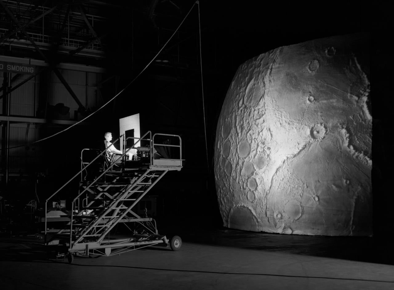
Test subject sitting at the controls: Project LOLA or Lunar Orbit and Landing Approach was a simulator built at Langley to study problems related to landing on the lunar surface. It was a complex project that cost nearly $2 million dollars. James Hansen wrote: "This simulator was designed to provide a pilot with a detailed visual encounter with the lunar surface; the machine consisted primarily of a cockpit, a closed-circuit TV system, and four large murals or scale models representing portions of the lunar surface as seen from various altitudes. The pilot in the cockpit moved along a track past these murals which would accustom him to the visual cues for controlling a spacecraft in the vicinity of the moon. Unfortunately, such a simulation--although great fun and quite aesthetic--was not helpful because flight in lunar orbit posed no special problems other than the rendezvous with the LEM, which the device did not simulate. Not long after the end of Apollo, the expensive machine was dismantled." (p. 379) Ellis J. White further described this simulator in his paper , "Discussion of Three Typical Langley Research Center Simulation Programs," (Paper presented at the Eastern Simulation Council (EAI's Princeton Computation Center), Princeton, NJ, October 20, 1966.) "A typical mission would start with the first cart positioned on model 1 for the translunar approach and orbit establishment. After starting the descent, the second cart is readied on model 2 and, at the proper time, when superposition occurs, the pilot's scene is switched from model 1 to model 2. then cart 1 is moved to and readied on model 3. The procedure continues until an altitude of 150 feet is obtained. The cabin of the LM vehicle has four windows which represent a 45 degree field of view. The projection screens in front of each window represent 65 degrees which allows limited head motion before the edges of the display can be seen. The lunar scene is presented to the pilot by rear projection on the screens with four Schmidt television projectors. The attitude orientation of the vehicle is represented by changing the lunar scene through the portholes determined by the scan pattern of four orthicons. The stars are front projected onto the upper three screens with a four-axis starfield generation (starball) mounted over the cabin and there is a separate starball for the low window." -- Published in James R. Hansen, Spaceflight Revolution: NASA Langley Research Center From Sputnik to Apollo, (Washington: NASA, 1995), p. 379.