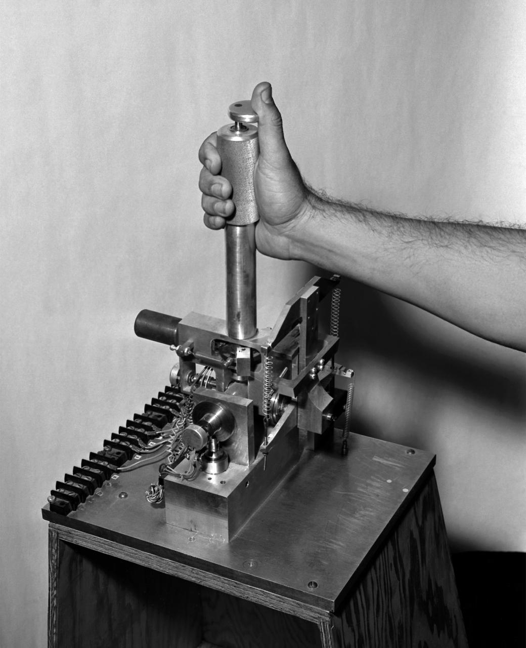
A photo of the control stick used on the Iron Cross Attitude Simulator. Although it resembled today's desktop computer flight sticks, its operation was different. As with a standard control stick, moving it back and forth raised and lowered the nose resulting in changes in pitch. Moving the stick to the right or left raised or lowered the wing, resulted in changes in roll. This control stick had a third axis, not found in standard control sticks. Twisting the stick to the right or left caused the airplane's nose to move horizontally in the same direction, resulting in changes in yaw.
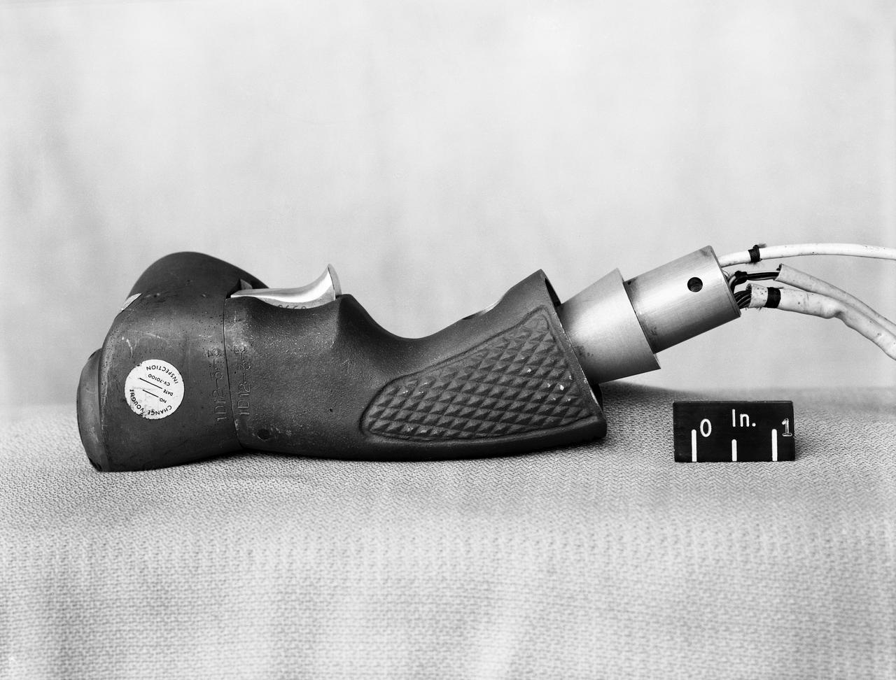
F8U-3 stick modifications - Stick controls in studio.
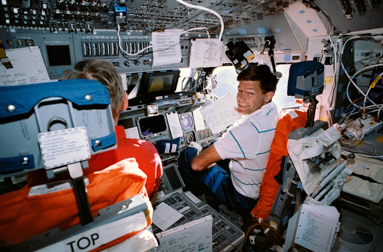
STS054-30-022 (13-19 Jan 1993) --- Astronaut Donald R. McMonagle (right), pilot, shares the forward flight deck with astronaut John H. Casper, mission commander, as the pair performs a maneuver of the Shuttle Endeavour in Earth orbit. The photograph was taken with a 35mm camera.
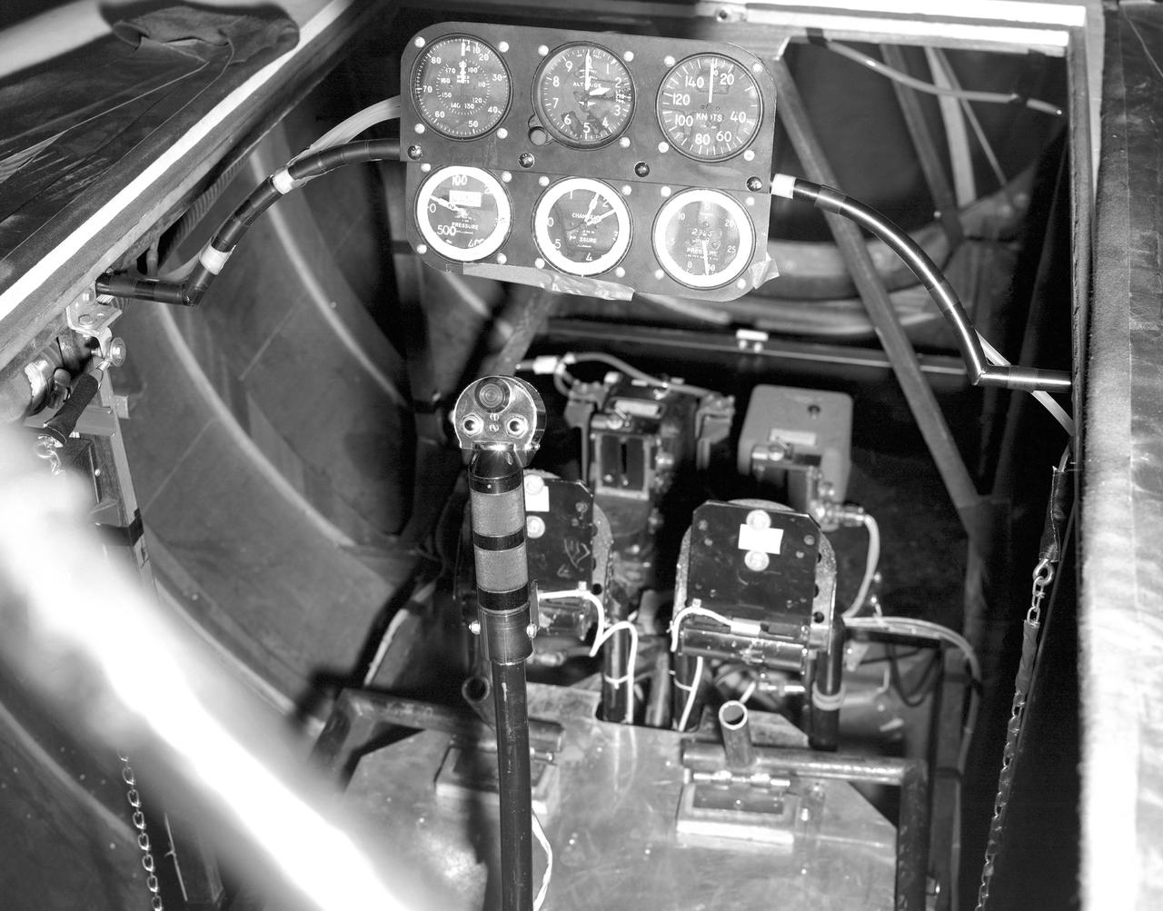
This photo shows the cockpit configuration of the M2-F1 wingless lifting body. With a top speed of about 120 knots, the M2-F1 had a simple instrument panel. Besides the panel itself, the ribs of the wooden shell (left) and the control stick (center) are also visible.
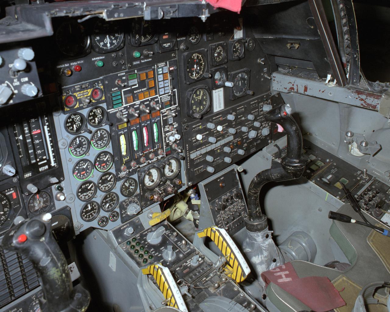
View of the right cockpit of the F-111 MAW aircraft. Unlike most fighter aircraft of the time, the F-111 had side-by-side seating. The pilot sat on the left side, and the weapons systems officer on the right. Both had control sticks to fly the aircraft.
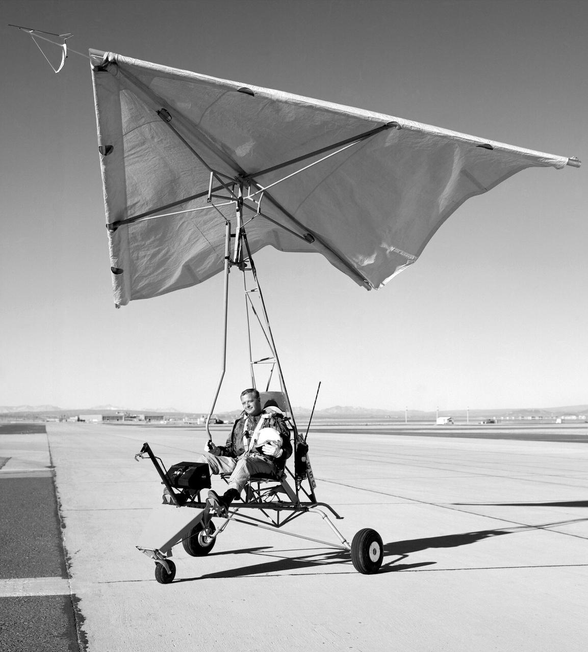
Test pilot Milton Thompson sitting in NASA Flight Research Center-built Paresev 1 (Paraglider Research Vehicle) on the taxi strip in front of the NASA Flight Research Center in 1962. In this photo the control stick can be seen coming from overhead and hanging in front of the pilot. The control system was a direct link with the wing membrane made of doped Irish linen. By maintaining simplicity during construction, it was possible to make control and configuration changes overnight and, in many instances, in minutes.
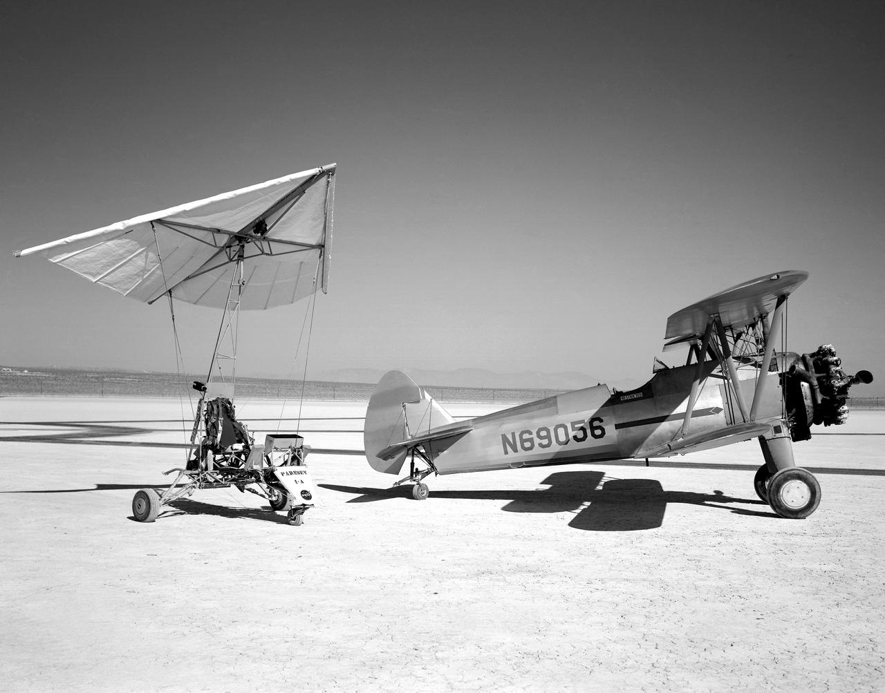
The Paresev 1-A (Paraglider Research Vehicle) and the tow airplane, 450-hp Stearman sport Biplane, sitting on Rogers dry lakebed, Edwards, California. The control system in the Paresev 1-A had a more conventional control stick position and was cable-operated; the main landing gear used shocks and bungees with the 100-square-foot wing membrane being made of 6-ounce unsealed Dacron.
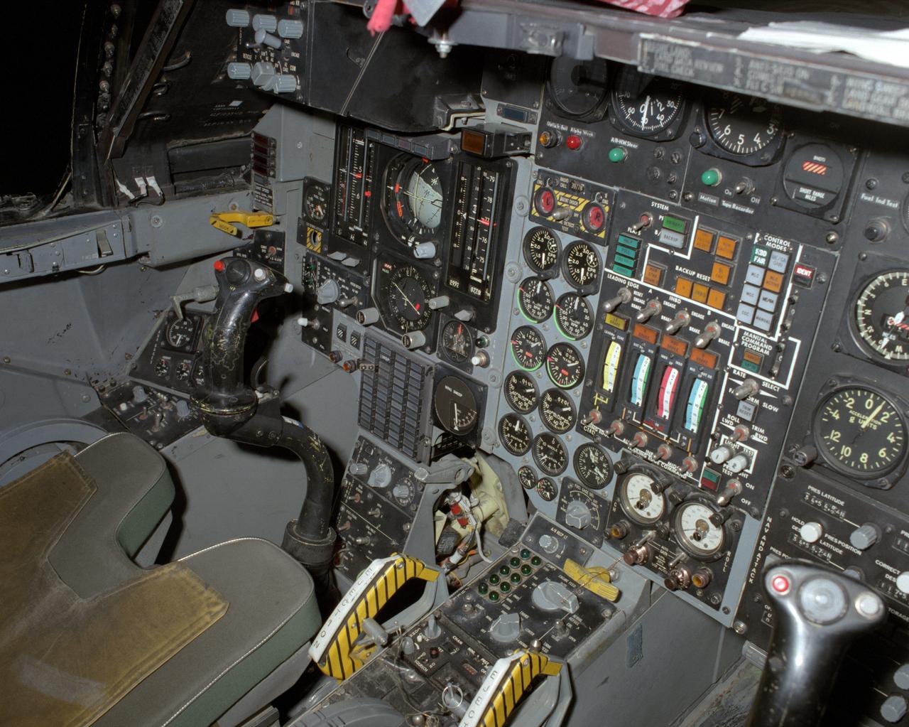
View of the left cockpit and pilot's seat of the F-111 MAW aircraft. Unlike most fighter aircraft of the time, the F-111 had side-by-side seating. The pilot sat on the left side, and the weapons systems officer on the right. Both had control sticks to fly the aircraft. The two yellow and black striped handles would be used in an emergency to eject the entire F-111 cockpit. The F-111 also did not have ejection seats, but used a capsule.
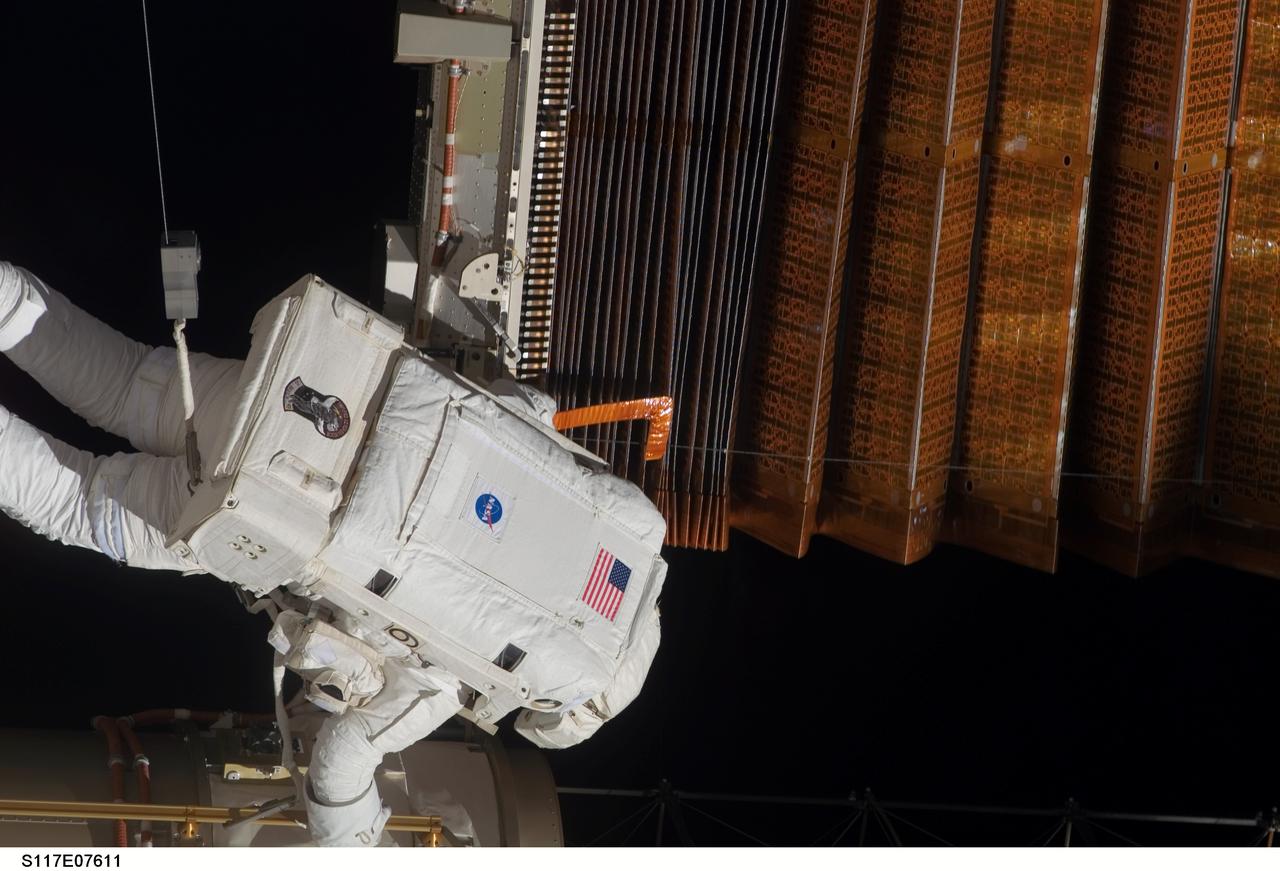
S117-E-07611 (15 June 2007) --- Astronaut John "Danny" Olivas uses a homemade "hockey stick" tool to fluff a solar array panel during the 7-hour and 58-minute spacewalk he performed with astronaut Jim Reilly on June 15. The two mission specialists had several tasks to perform, all of which they completed successfully. After working on separate tasks, the two astronauts joined forces with their colleagues inside the shuttle and station and flight controllers in Houston to complete the delicate process of folding an older solar array so that it can be moved from its temporary location to its permanent home during a shuttle mission this fall.
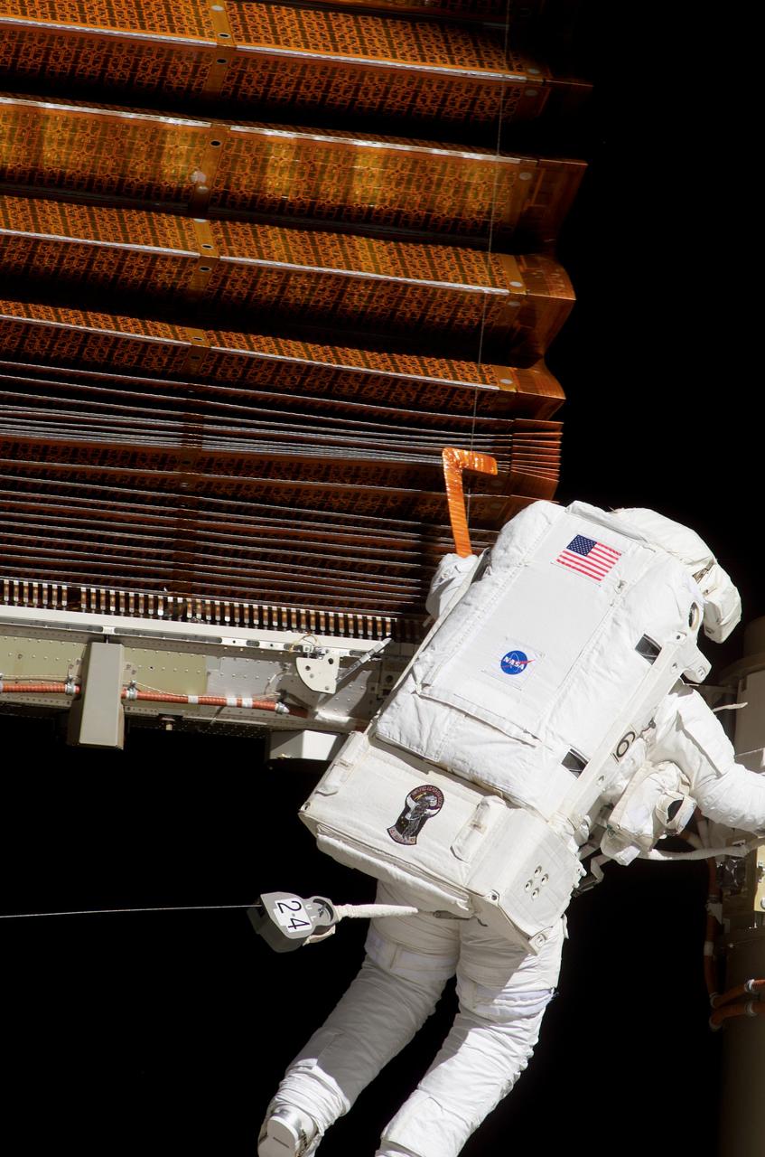
S117-E-07612 (15 June 2007) --- Astronaut John "Danny" Olivas uses a homemade "hockey stick" tool to fluff a solar array panel during the 7-hour and 58-minute spacewalk he performed with astronaut Jim Reilly on June 15. The two mission specialists had several tasks to perform, all of which they completed successfully. After working on separate tasks, the two astronauts joined forces with their colleagues inside the shuttle and station and flight controllers in Houston to complete the delicate process of folding an older solar array so that it can be moved from its temporary location to its permanent home during a shuttle mission this fall.
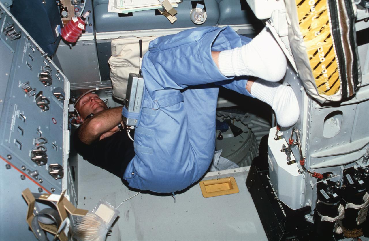
STS003-22-113 (24 March 1982) --- Astronaut Gordon Fullerton, STS-3 pilot, wearing communication kit assembly mini-headset (HDST), sleeps on aft flight deck resting his back against the floor and his feet against commander's ejection seat (S1) back. On-orbit station control panel A8 and payload station panel L15 appear above Fullerton. Special clips for holding notebooks open and beverage containers are velcroed on various panels. Photo credit: NASA
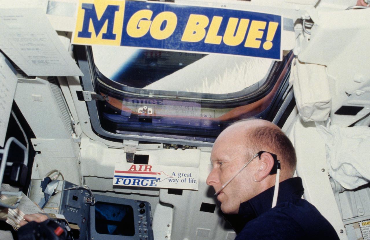
S82-28906 (27 March 1982) --- Astronaut C. Gordon Fullerton, STS-3 pilot, mans the right hand aft station of the flight deck on the Earth-orbiting Columbia. The photograph was taken with a 35mm camera by astronaut Jack R. Lousma, crew commander. The "Go Blue" sticker is a University of Michigan memento of Lousma, and the Air Force sign was put up by Fullerton, a USAF colonel. Lousma, a USMC colonel, received his BS degree in aeronautical engineering in 1959 from UM. One of two aft windows for cargo bay viewing and one of two ceiling windows are visible in the photo. Fullerton and Lousma watched the activity of the remote manipulator system (RMS) arm out the lower window and they took a number of photos of Earth from the upper window. Photo credit: NASA
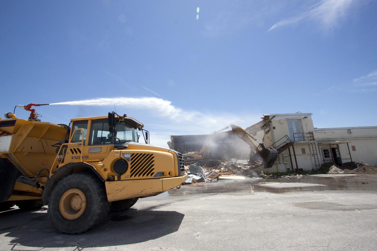
CAPE CANAVERAL, Fla. – At Cape Canaveral Air Force Station in Florida, a custom-built end dump truck spews water over the Mercury Mission Control Center to reduce the particles dispensed into the air by a Caterpillar 330 track-hoe tearing down the building. The truck's operator controls the water spray using joy sticks installed in the cab of the truck. The original building, constructed between 1956 and 1958, was last modified in 1963. The center succumbed to the two worst enemies of structures along the space coast - time and salt air - necessitating that it be demolished as a safety measure. The facility served as mission control during all the Project Mercury missions, as well as the first three flights of the Gemini Program. The center housed the flight controllers whose duty was to take over flight control after liftoff and follow it through until splashdown. Additionally, it supported vehicle checkout, spacecraft tracking, and astronaut training. With Gemini IV, mission control moved to Houston, and the facility took on the roles of launch control and tracking station. In 1999, much of the equipment and furnishings from the flight control area was moved to Kennedy Space Center's Visitor Complex. A re-created mission control room currently is on display in the complex's Dr. Kurt H. Debus Conference Facility. Speegle II of Cocoa, Fla., was awarded the contract for the deconstruction project. Frank-Lin Excavating is performing the demolition for Sunrise Systems of Brevard, a subcontractor to Speegle II. Photo credit: NASA_Jack Pfaller
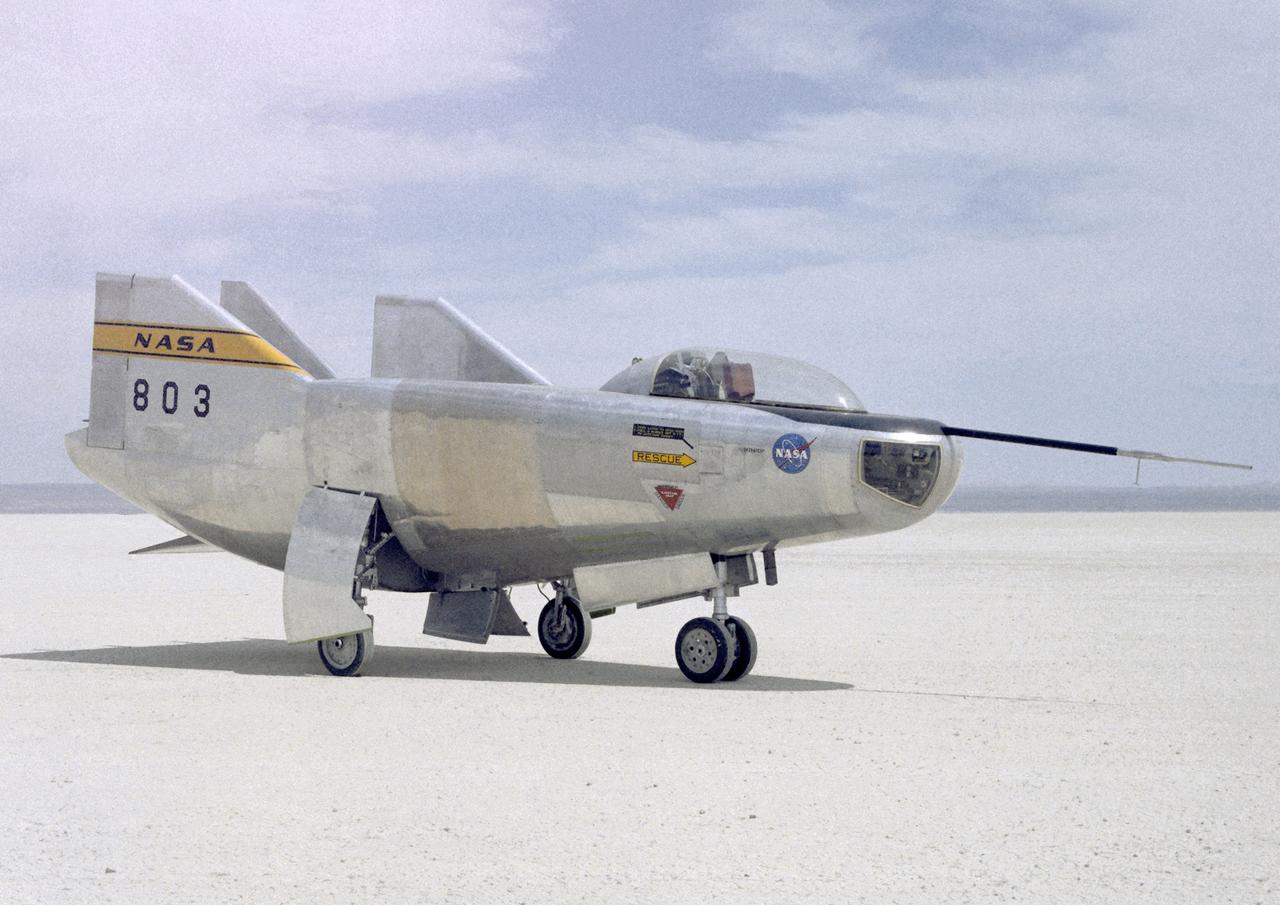
The M2-F3 Lifting Body is seen here on the lakebed next to the NASA Flight Research Center (FRC--later Dryden Flight Research Center), Edwards, California. The May 1967 crash of the M2-F2 had torn off the left fin and landing gear. It had also damaged the external skin and internal structure. Flight Research Center engineers worked with Ames Research Center and the Air Force in redesigning the vehicle with a center fin to provide greater stability. Then Northrop Corporation cooperated with the FRC in rebuilding the vehicle. The entire process took three years.
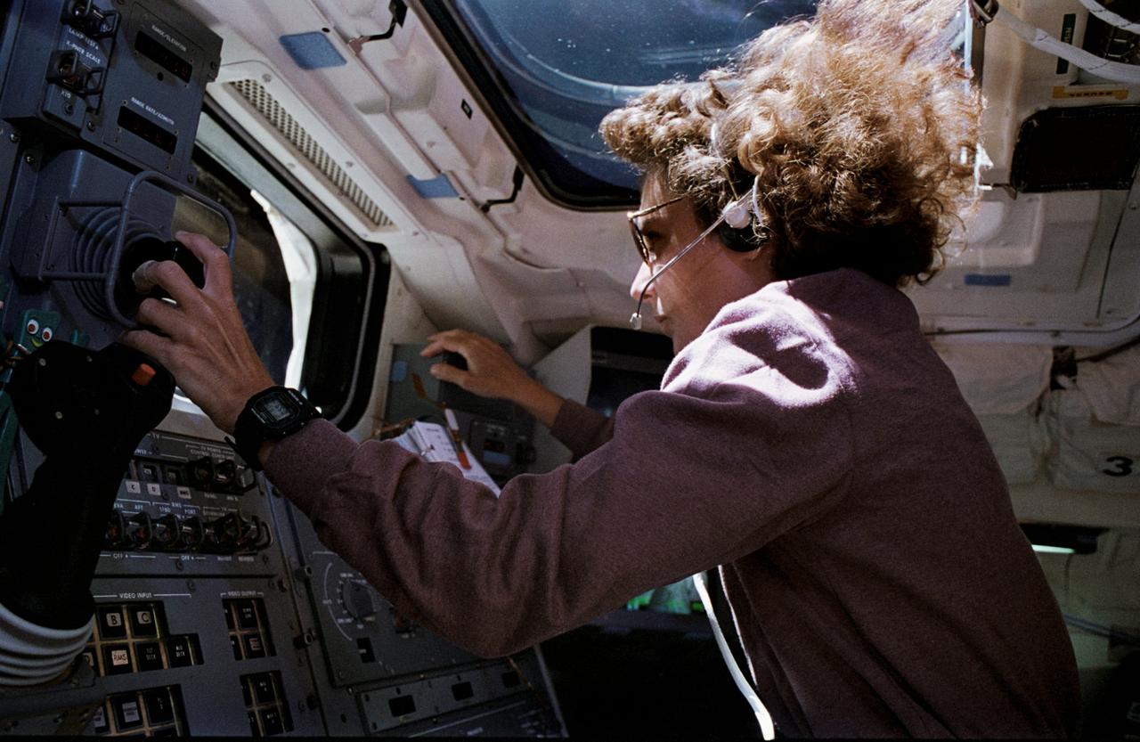
STS057-31-030 (25 June 1993) --- Astronaut Nancy J. Sherlock operates Endeavour's remote manipulator system (RMS) during the June 25 extravehicular activity of two crewmates. At one point, astronaut G. David Low, while his feet were anchored to a special restraint device on the end of the RMS arm, moved about, with Sherlock's aid, while holding astronaut Peter J. K. (Jeff) Wisoff. The activity represented an evaluation of techniques which might be used on planned future missions -- a 1993 servicing visit to the Hubble Space Telescope and later space station work -- which will require astronauts to frequently lift objects of similar sized bulk.
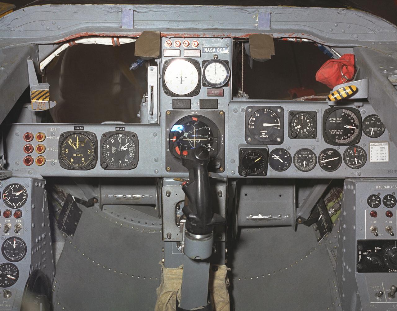
This photo shows the cockpit instrument panel of the M2-F3 Lifting Body.
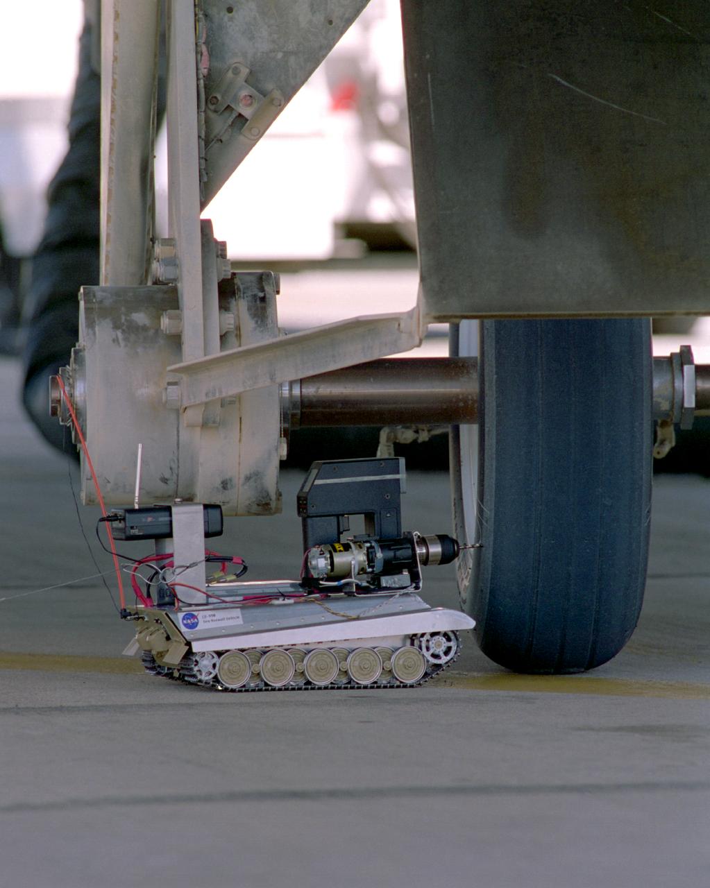
Created from a 1/16th model of a German World War II tank, the TAV (Tire Assault Vehicle) was an important safety feature for the Convair 990 Landing System Research Aircraft, which tested space shuttle tires. It was imperative to know the extreme conditions the shuttle tires could tolerate at landing without putting the shuttle and its crew at risk. In addition, the CV990 was able to land repeatedly to test the tires. The TAV was built from a kit and modified into a radio controlled, video-equipped machine to drill holes in aircraft test tires that were in imminent danger of exploding because of one or more conditions: high air pressure, high temperatures, and cord wear. An exploding test tire releases energy equivalent to two and one-half sticks of dynamite and can cause severe injuries to anyone within 50 ft. of the explosion, as well as ear injury - possibly permanent hearing loss - to anyone within 100 ft. The degree of danger is also determined by the temperature pressure and cord wear of a test tire. The TAV was developed by David Carrott, a PRC employee under contract to NASA.
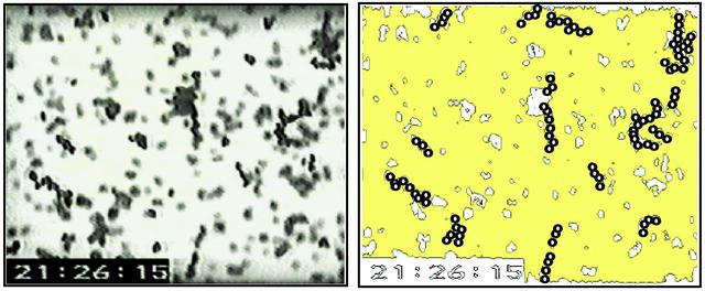
John Marshall, an investigator at Ames Research Center and a principal investigator in the microgravity fluid physics program, is studying the adhesion and cohesion of particles in order to shed light on how granular systems behave. These systems include everything from giant dust clouds that form planets to tiny compressed pellets, such as the ones you swallow as tablets. This knowledge should help us control the grains, dust, and powders that we encounter or use on a daily basis. Marshall investigated electrostatic charge in microgravity on the first and second U.S. Microgravity Laboratory shuttle missions to see how grains aggregate, or stick together. With gravity's effects eliminated on orbit, Marshall found that the grains of sand that behaved ever so freely on Earth now behaved like flour. They would just glom together in clumps and were quite difficult to disperse. That led to an understanding of the prevalence of the electrostatic forces. The granules wanted to aggregate as little chains, like little hairs, and stack end to end. Some of the chains had 20 or 30 grains. This phenomenon indicated that another force, what Marshall believes to be an electrostatic dipole, was at work.(The diagram on the right emphasizes the aggregating particles in the photo on the left, taken during the USML-2 mission in 1995.)
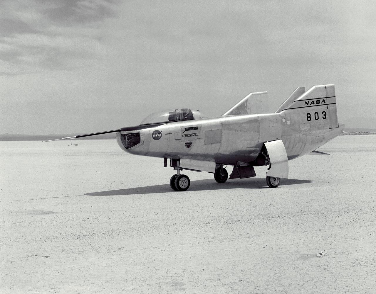
The M2-F3 Lifting Body is seen here on the lakebed at the NASA Flight Research Center (FRC--later the Dryden Flight Research Center), Edwards, California. After a three-year-long redesign and rebuilding effort, the M2-F3 was ready to fly. The May 1967 crash of the M2-F2 had damaged both the external skin and the internal structure of the lifting body. At first, it seemed that the vehicle had been irreparably damaged, but the original manufacturer, Northrop, did the repair work and returned the redesigned M2-F3 with a center fin for stability to the FRC.
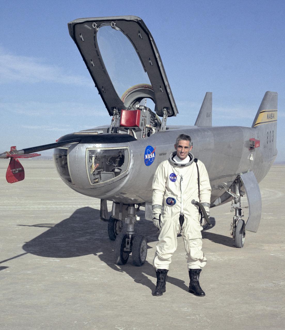
NASA research pilot John A. Manke is seen here in front of the M2-F3 Lifting Body. Manke was hired by NASA on May 25, 1962, as a flight research engineer. He was later assigned to the pilot's office and flew various support aircraft including the F-104, F5D, F-111 and C-47. After leaving the Marine Corps in 1960, Manke worked for Honeywell Corporation as a test engineer for two years before coming to NASA. He was project pilot on the X-24B and also flew the HL-10, M2-F3, and X-24A lifting bodies. John made the first supersonic flight of a lifting body and the first landing of a lifting body on a hard surface runway. Manke served as Director of the Flight Operations and Support Directorate at the Dryden Flight Research Center prior to its integration with Ames Research Center in October 1981. After this date John was named to head the joint Ames-Dryden Directorate of Flight Operations. He also served as site manager of the NASA Ames-Dryden Flight Research Facility. John is a member of the Society of Experimental Test Pilots. He retired on April 27, 1984.
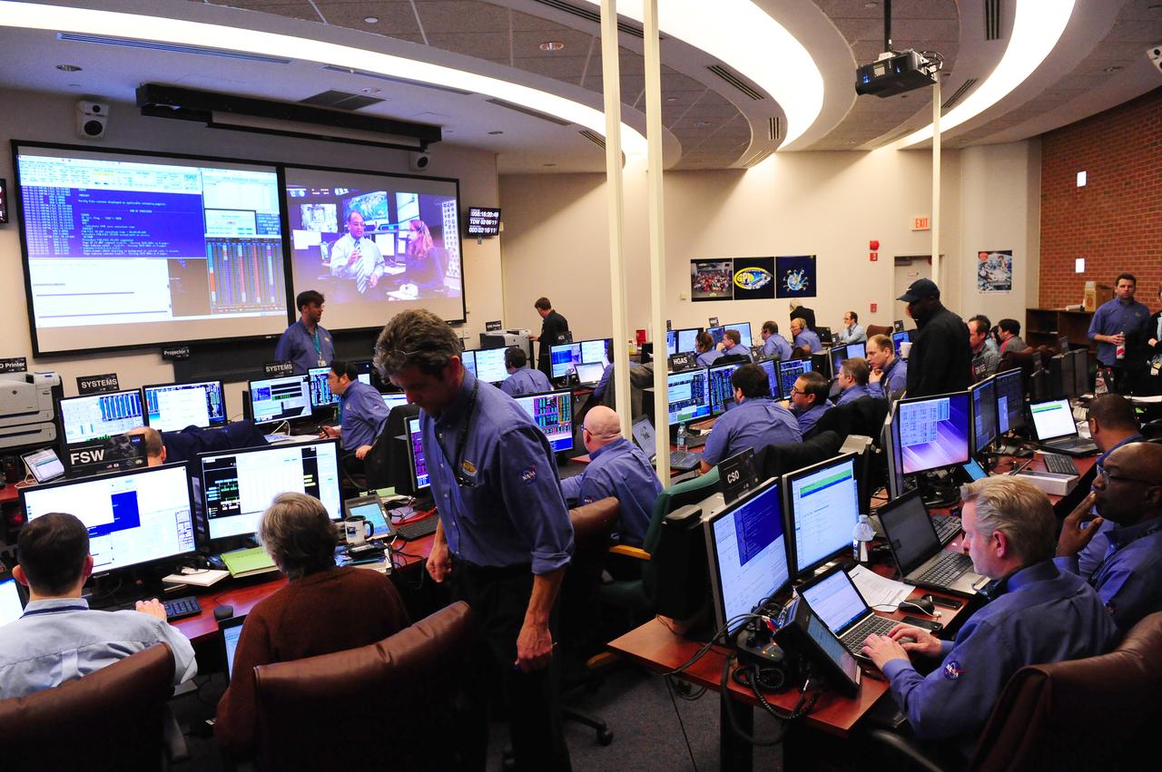
One of the control rooms at NASA’s Goddard Space Flight Center in Greenbelt, Md., prepares for the GPM mission’s Core Observatory on Feb. 27, 2014. <b>Credit: NASA's Goddard Space Flight Center/Debbie McCallum</b> GPM's Core Observatory is poised for launch from the Japan Aerospace Exploration Agency's Tanegashima Space Center, scheduled for the afternoon of Feb. 27, 2014 (EST). GPM is a joint venture between NASA and the Japan Aerospace Exploration Agency. The GPM Core Observatory will link data from a constellation of current and planned satellites to produce next-generation global measurements of rainfall and snowfall from space. The GPM mission is the first coordinated international satellite network to provide near real-time observations of rain and snow every three hours anywhere on the globe. The GPM Core Observatory anchors this network by providing observations on all types of precipitation. The observatory's data acts as the measuring stick by which partner observations can be combined into a unified data set. The data will be used by scientists to study climate change, freshwater resources, floods and droughts, and hurricane formation and tracking. <b><a href="http://www.nasa.gov/audience/formedia/features/MP_Photo_Guidelines.html" rel="nofollow">NASA image use policy.</a></b> <b><a href="http://www.nasa.gov/centers/goddard/home/index.html" rel="nofollow">NASA Goddard Space Flight Center</a></b> enables NASA’s mission through four scientific endeavors: Earth Science, Heliophysics, Solar System Exploration, and Astrophysics. Goddard plays a leading role in NASA’s accomplishments by contributing compelling scientific knowledge to advance the Agency’s mission. <b>Follow us on <a href="http://twitter.com/NASAGoddardPix" rel="nofollow">Twitter</a></b> <b>Like us on <a href="http://www.facebook.com/pages/Greenbelt-MD/NASA-Goddard/395013845897?ref=tsd" rel="nofollow">Facebook</a></b> <b>Find us on <a href="http://instagram.com/nasagoddard?vm=grid" rel="nofollow">Instagram</a></b>
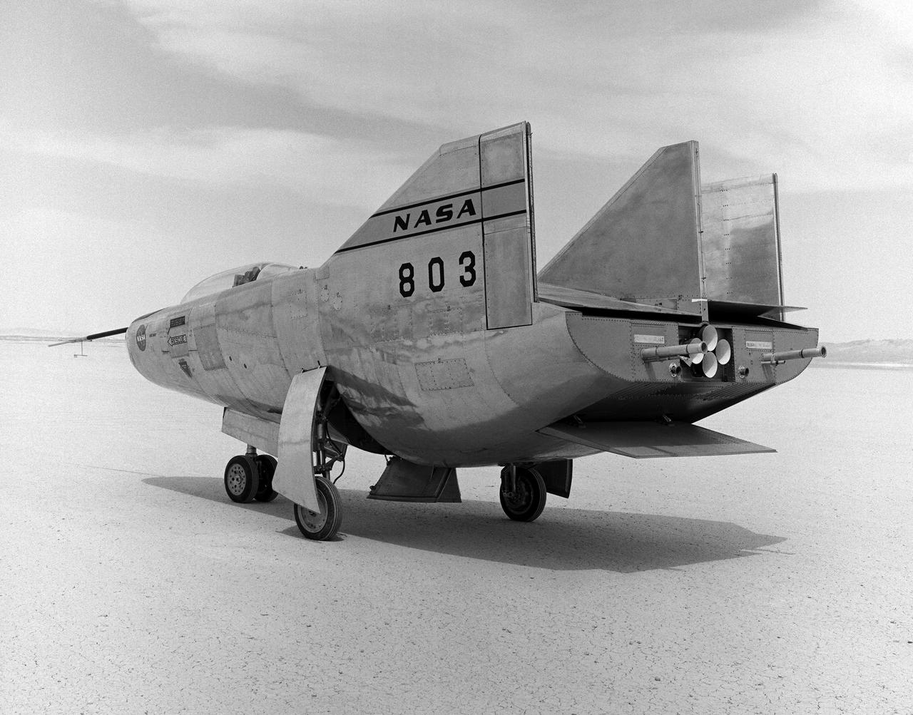
The M2-F3 Lifting Body is seen here on the lakebed next to the NASA Flight Research Center (later the Dryden Flight Research Center), Edwards, California. Redesigned and rebuilt from the M2-F2, the M2-F3 featured as its most visible change a center fin for greater stability. While the M2-F3 was still demanding to fly, the center fin eliminated the high risk of pilot induced oscillation (PIO) that was characteristic of the M2-F2.
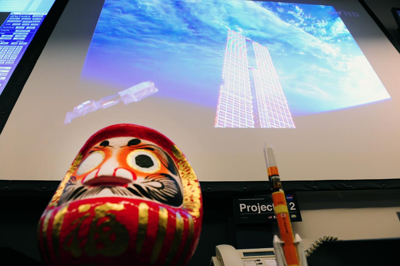
The Daruma doll is a symbol of good luck and in Japan is often given as a gift for encouragement to reach a goal. When the goal is set, one eye is colored in. When the goal is achieved, the other eye is colored. <a href="http://www.flickr.com/photos/nasahqphoto/12714130984/in/set-72157641344480584" target="_blank">An identical doll</a> sits in the control room at the Japan Aerospace Agency’s (JAXA) Tanegashima Space Center, leading up to the launch of the joint NASA-JAXA Global Precipitation Measurement mission’s Core Observatory. <b>Credit: NASA's Goddard Space Flight Center/Debbie McCallum</b> GPM's Core Observatory is poised for launch from the Japan Aerospace Exploration Agency's Tanegashima Space Center, scheduled for the afternoon of Feb. 27, 2014 (EST). GPM is a joint venture between NASA and the Japan Aerospace Exploration Agency. The GPM Core Observatory will link data from a constellation of current and planned satellites to produce next-generation global measurements of rainfall and snowfall from space. The GPM mission is the first coordinated international satellite network to provide near real-time observations of rain and snow every three hours anywhere on the globe. The GPM Core Observatory anchors this network by providing observations on all types of precipitation. The observatory's data acts as the measuring stick by which partner observations can be combined into a unified data set. The data will be used by scientists to study climate change, freshwater resources, floods and droughts, and hurricane formation and tracking. <b><a href="http://www.nasa.gov/audience/formedia/features/MP_Photo_Guidelines.html" rel="nofollow">NASA image use policy.</a></b> <b><a href="http://www.nasa.gov/centers/goddard/home/index.html" rel="nofollow">NASA Goddard Space Flight Center</a></b> enables NASA’s mission through four scientific endeavors: Earth Science, Heliophysics, Solar System Exploration, and Astrophysics. Goddard plays a leading role in NASA’s accomplishments by contributing compelling scientific knowledge to advance the Agency’s mission. <b>Follow us on <a href="http://twitter.com/NASAGoddardPix" rel="nofollow">Twitter</a></b> <b>Like us on <a href="http://www.facebook.com/pages/Greenbelt-MD/NASA-Goddard/395013845897?ref=tsd" rel="nofollow">Facebook</a></b> <b>Find us on <a href="http://instagram.com/nasagoddard?vm=grid" rel="nofollow">Instagram</a></b>