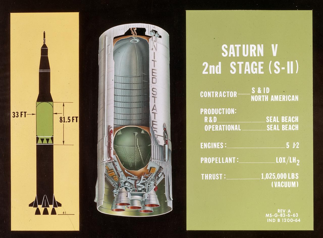
This illustration, with callouts, is of the Saturn V SII (2nd Stage) developed by the Space Division of North American Aviation under the direction of the Marshall Space Flight Center. The 82-foot-long and 33-foot-diameter S-II stage utilized five J-2 engines, each with a 200,000-pound thrust capability. The engine used liquid oxygen and liquid hydrogen as its propellants.
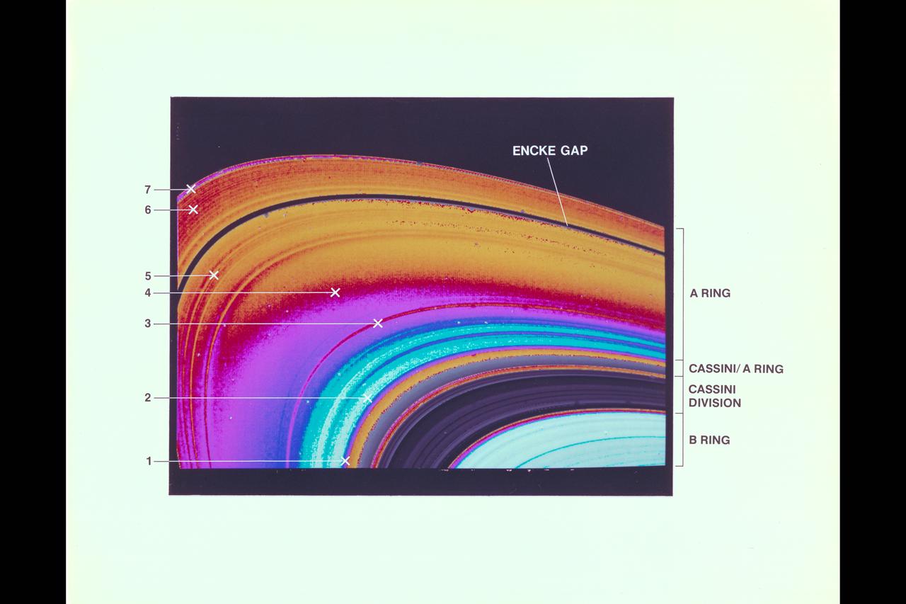
Saturn and it's rings, with callouts, as photographed by Voyager 2
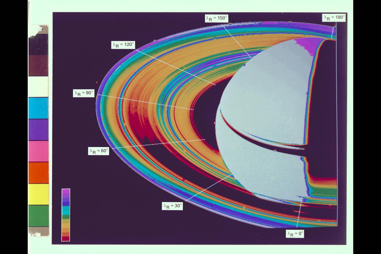
Saturn and it's rings, with callouts, as photographed by Voyager 2
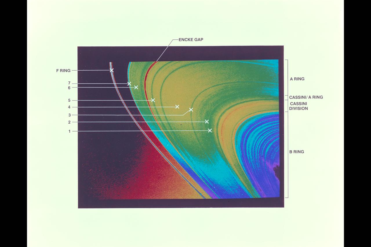
Saturn and it's rings, with callouts, as photographed by Voyager 2
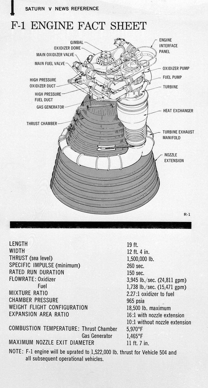
This figure is a drawing of the F-1 engine with callouts of the major components and the engine characteristics.

This figure is a line drawing of the J-2 engine with callouts of the major components and the engine characteristics.
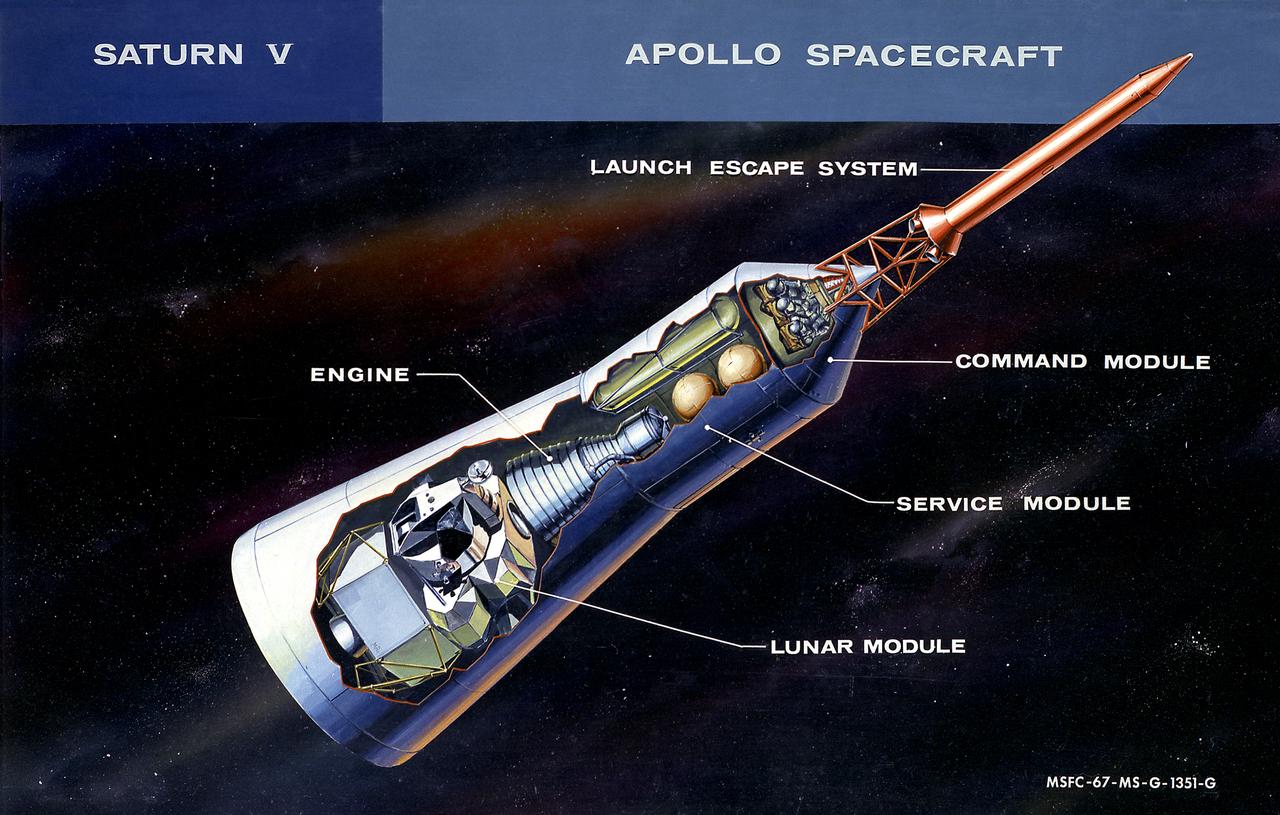
This cutaway illustration shows the Apollo Spacecraft with callouts of the major components. The spacecraft consisted of the lunar module, the service module, the command module, and the launch escape system.
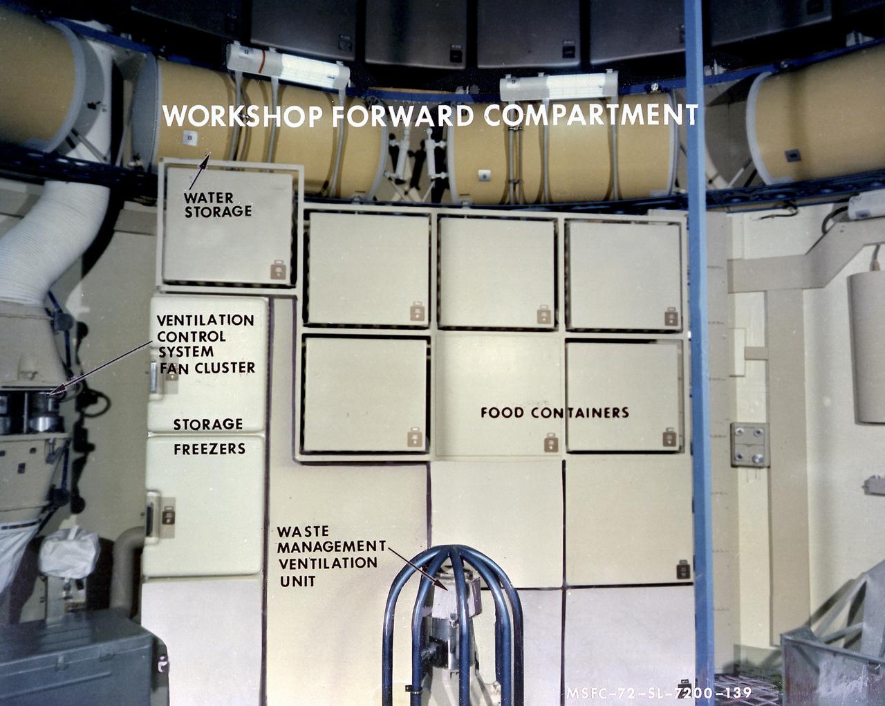
This image, with callouts, depicts the storage area of the forward compartment at the upper level of the Orbital Workshop (OWS). The upper level consisted of a large work area and housed water storage tanks, a food freezer, storage vaults for film, scientific airlocks, mobility and stability experiment equipment, and other experimental equipment.
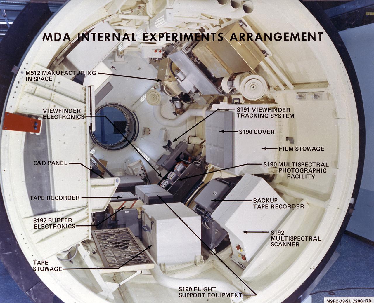
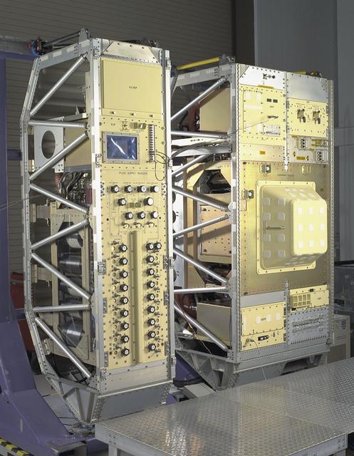
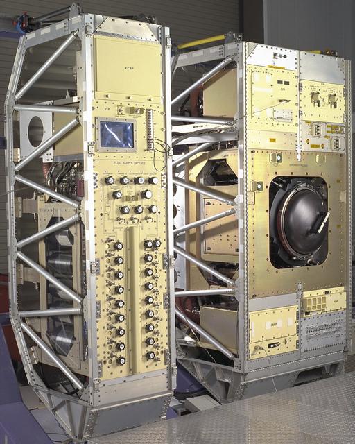
This photograph shows the internal configuration of Skylab's Multiple Docking Adapter (MDA), including callouts for its various internal experiments and facilities. Designed and manufactured by the Marshall Space Flight Center, the MDA housed a number of experiment control and stowage units and provided a docking port for the Apollo Command Module.
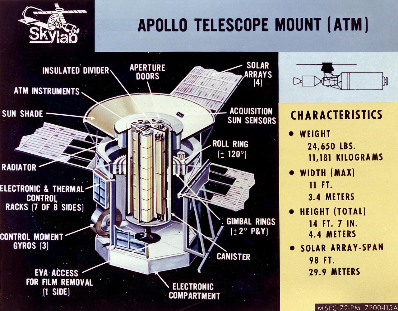
The Apollo Telescope Mount (ATM) served as the first marned astronomical observatory in space. It was designed for solar research from Earth orbit aboard the Skylab. This image is a cutaway illustration of the ATM canister with callouts and characteristics. The ATM was designed and developed by the Marshall Space Flight Center.
Exterior view of Combustion Module-2 with callouts to identify key sections. The original CM flew on the Microgravity Sciences Lab-1 and 1R in 1997. It has been refurbished and placed in new racks for flight on the STS-107 Research 1 mission in 2001. Glenn Research in Cleveland, OH, manages the project.
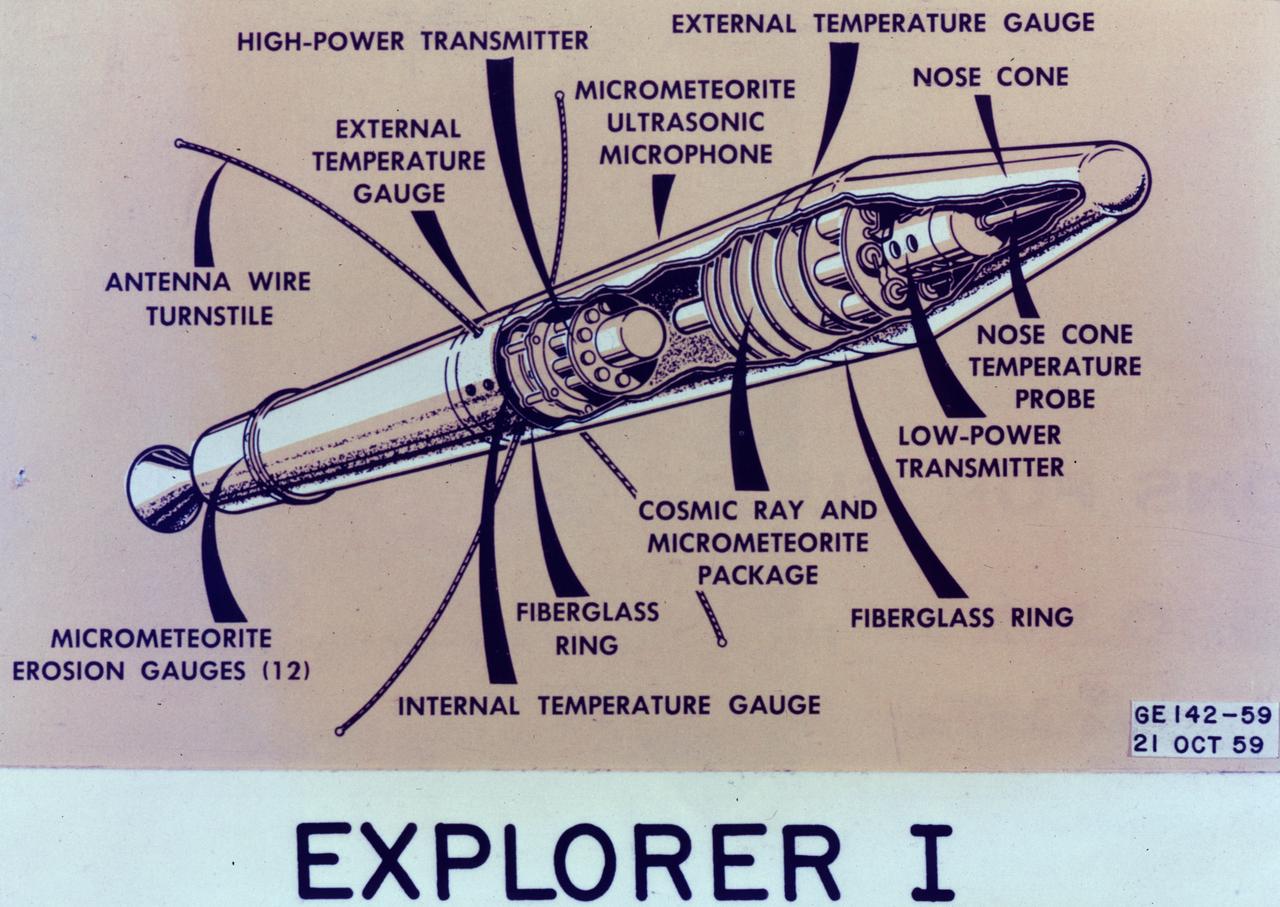
This image is a cutaway illustration of the Explorer I satellite with callouts. The Explorer I satellite was America's first scientific satellite launched aboard the Jupiter C launch vehicle on January 31, 1958. The Explorer I carried the radiation detection experiment designed by Dr. James Van Allen and discovered the Van Allen Radiation Belt.
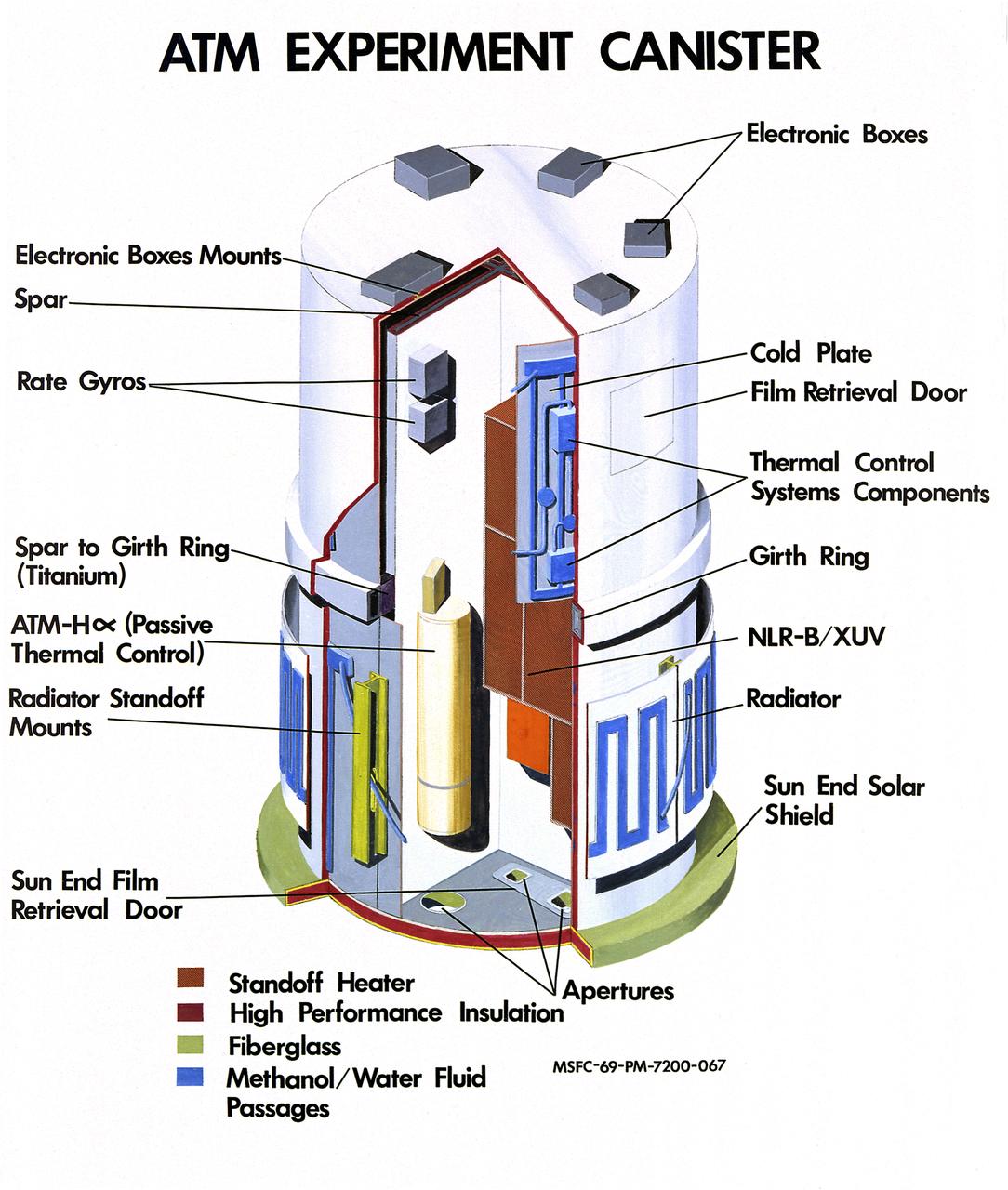
The Apollo Telescope Mount (ATM) served as the first marned astronomical observatory in space. It was designed for solar research from Earth orbit aboard the Skylab. This image is a cutaway illustration of the ATM canister with callouts. The ATM was designed and developed by the Marshall Space Flight Center.
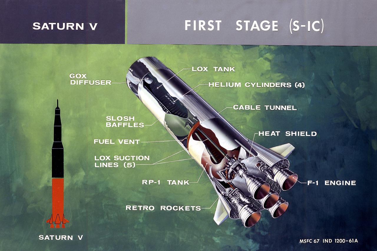
This illustration shows a cutaway drawing with callouts of the major components for the S-IC (first) stage of the Saturn V launch vehicle. The S-IC stage is 138 feet long and 33 feet in diameter, producing more than 7,500,000 pounds of thrust through five F-1 engines powered by liquid oxygen and kerosene. Four of the engines are mounted on an outer ring and gimball for control purposes. The fifth engine is rigidly mounted in the center. When ignited, the roar produced by the five engines equals the sound of 8,000,000 hi-fi sets.
Exterior view of Combustion Module-2 with the Experiment Module covered. The original CM flew on the Microgravity Sciences Lab-1 and 1R in 1997. It has been refurbished and placed in new racks for flight on the STS-107 Research 1 mission in 2001. See MSFC 0100158 for a view with callouts. Glenn Research in Cleveland, OH, manages the project.
Exterior view of Combustion Module-2 with the Experiment Module cover (black dome) exposed. The original CM flew on the Microgravity Sciences Lab-1 and 1R in 1997. It has been refurbished and placed in new racks for flight on the STS-107 Research 1 mission in 2001. See MSFC 0100158 for a view with callouts. Glenn Research in Cleveland, OH, manages the project.
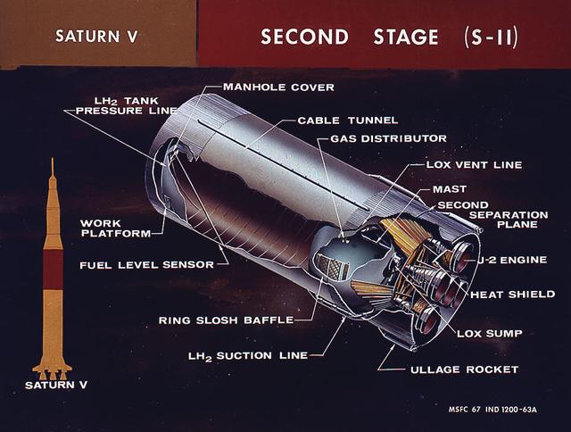
This cutaway illustration shows the Saturn V S-II (second) stage with callouts of major components. When the Saturn V first stage burns out and drops away, power for the Saturn was provided by the S-II (second) stage with five J-2 engines which produced a total of 1,150,000 pounds of thrust. Four outer engines are placed in a square pattern with gimbaling capability for control and guidance, with the fifth engine fixed rigidly in the center.
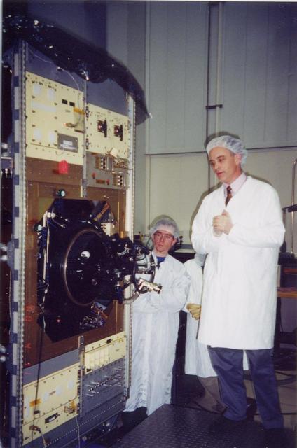
Exterior view of Combustion Module-2 with an Experiment Module partially extracted during a crew training session. The original CM flew on the Microgravity Sciences Lab-1 and 1R in 1997. It has been refurbished and placed in new racks for flight on the STS-107 Research 1 mission in 2001. See MSFC 0100158 for a view with callouts. Glenn Research in Cleveland, OH, manages the project.
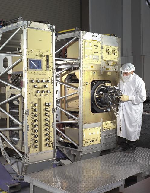
Exterior view of Combustion Module-2 with an Experiment Module partially extracted during a crew training session. The original CM flew on the Microgravity Sciences Lab-1 and 1R in 1997. It has been refurbished and placed in new racks for flight on the STS-107 Research 1 mission in 2001. See MSFC 0100158 for a view with callouts. Glenn Research in Cleveland, OH, manages the project.
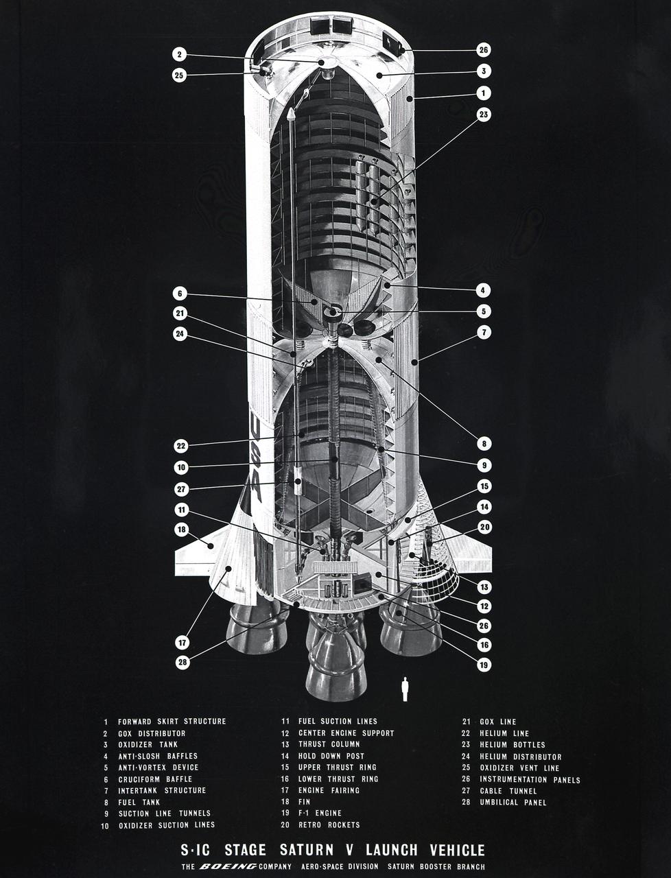
This cutaway illustration shows the Saturn V S-IC (first) stage with detailed callouts of the components. The S-IC Stage is 138 feet long and 33 feet in diameter, producing 7,500,000 pounds of thrust through five F-1 engines that are powered by liquid oxygen and kerosene. Four of the engines are mounted on an outer ring and gimbal for control purposes. The fifth engine is rigidly mounted in the center. When ignited, the roar produced by the five engines equals the sound of 8,000,000 hi-fi sets.
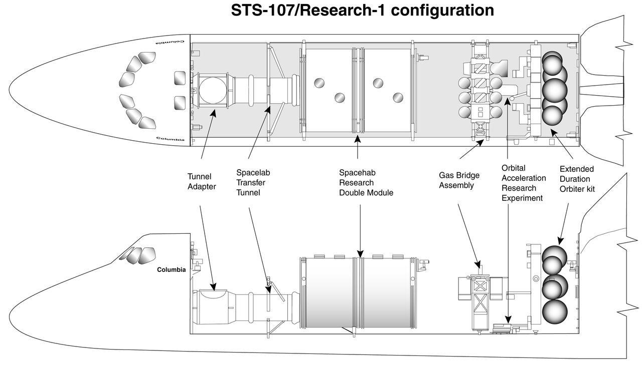
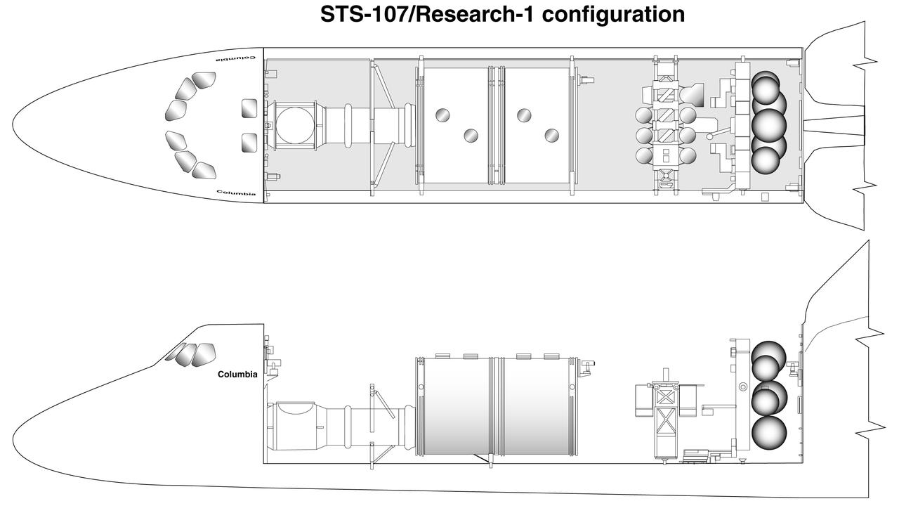
This diagram shows the general arrangement of the payloads to be carried by the multidisciplinary STS-107 Research-1 Space Shuttle mission in 2002. The Spacehab module will host experiments that require direct operation by the flight crew. Others with special requirements will be on the GAS Bridge Assembly sparning the payload bay. The Extended Duration Orbiter kit carries additional oxygen and hydrogen for the electricity-producing fuel cells. Research-1 experiments will cover space biology, life science, microgravity research, and commercial space product development, research sponsored by NASA's Office of Biological and Physical Research. An alternative view without callouts is available at 0101765.
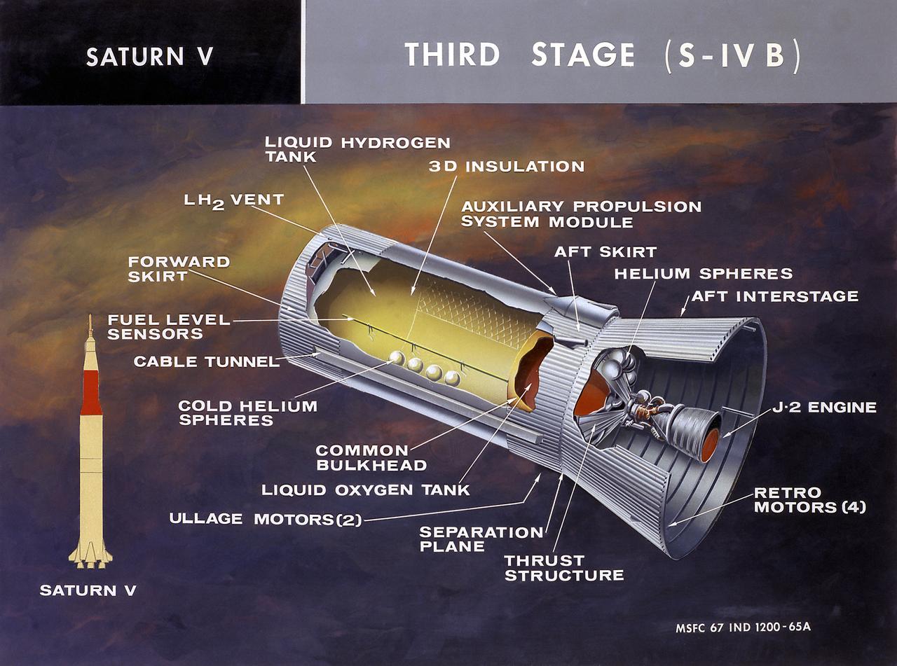
This cutaway illustration shows the Saturn V S-IVB (third) stage with the callouts of its major components. When the S-II (second) stage of the powerful Saturn V rocket burnt out and was separated the remaining units approached orbit around the Earth. Injection into the desired orbit was attaineded as the S-IVB (third stage) was ignited and burnt. The S-IVB stage was powered by a single 200,000-pound thrust J-2 engine and had a re-start capability built in for its J-2 engine. The S-IVB restarted to speed the Apollo spacecraft to escape velocity injecting it and the astronauts into a moon trajectory.
Thisdiagram shows the general arrangement of the payloads to be carried by the multidisciplinary STS-107 Research-1 Space Shuttle mission in 2002. The Spacehab module will host experiments that require direct operation by the flight crew. Others with special requirements will be on the GAS Bridge Assembly sparning the payload bay. The Extended Duration Orbiter kit carries additional oxygen and hydrogen for the electricity-producing fuel cells. Research-1 experiments will cover space biology, life science, microgravity research, and commercial space product development, research sponsored by NASA's Office of Biological and Physical Research. An alternative view with callouts is available at 0101764.
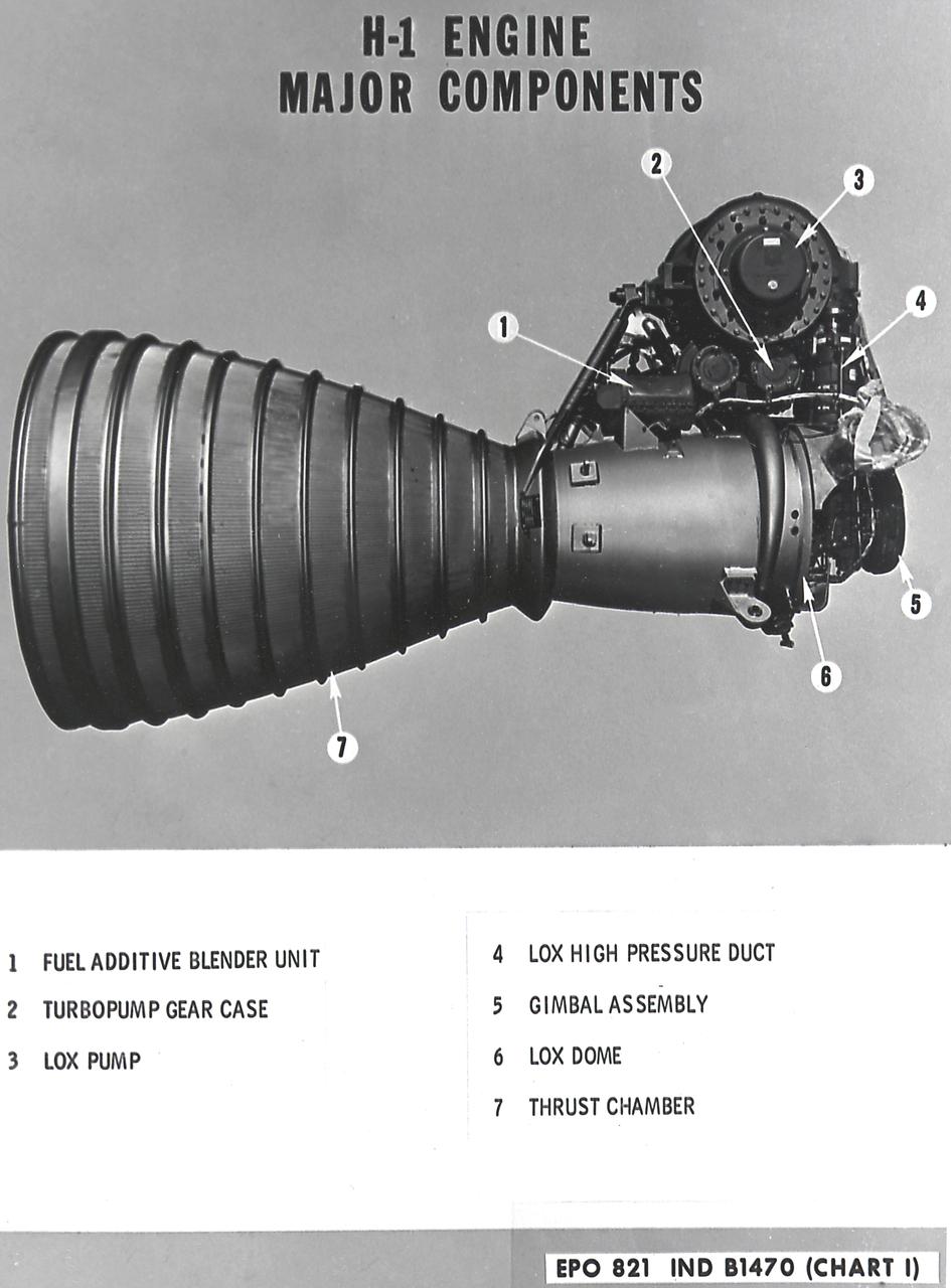
H-1 engine major components with callouts (chart 1). The H-1 engine was used in a cluster of eight on the the first stage of Saturn I (S-I stage) and Saturn IB (S-IB stage). The engines were arranged in a double pattern: four engines, located inboard, were fixed in a square pattern around the stage axis, while the remaining four engines were located outboard in a larger square pattern and each outer engine was gimbaled. Each H-1 engine had a thrust of 188,000 pounds for a combined thrust of over 1,500,000 pounds.
H-1 Engine major components with callouts (chart 1): The H-1 engine was used in a cluster of eight on the the first stage of Saturn I (S-I stage) and Saturn IB (S-IB stage). The engines were arranged in a double pattern: four engines, located inboard, were fixed in a square pattern around the stage axis, while the remaining four engines were located outboard in a larger square pattern and each outer engine was gimbaled. Each H-1 engine had a thrust of 188,000 pounds for a combined thrust of over 1,500,000 pounds.

The Kepler space telescope examined twenty-one patches of the sky during it’s nine and a half years of operation. Within these regions, Kepler gathered high precision brightness measurements of over half a million stars facilitating the discovery of thousands of exoplanets and yielding insight into a multitude of other astrophysical phenomena. Illustration by Wendy Stenzel, Ames Science content: Jeff Coughlin, Kenneth Mighell, Doug Caldwell, all of NASA Ames.
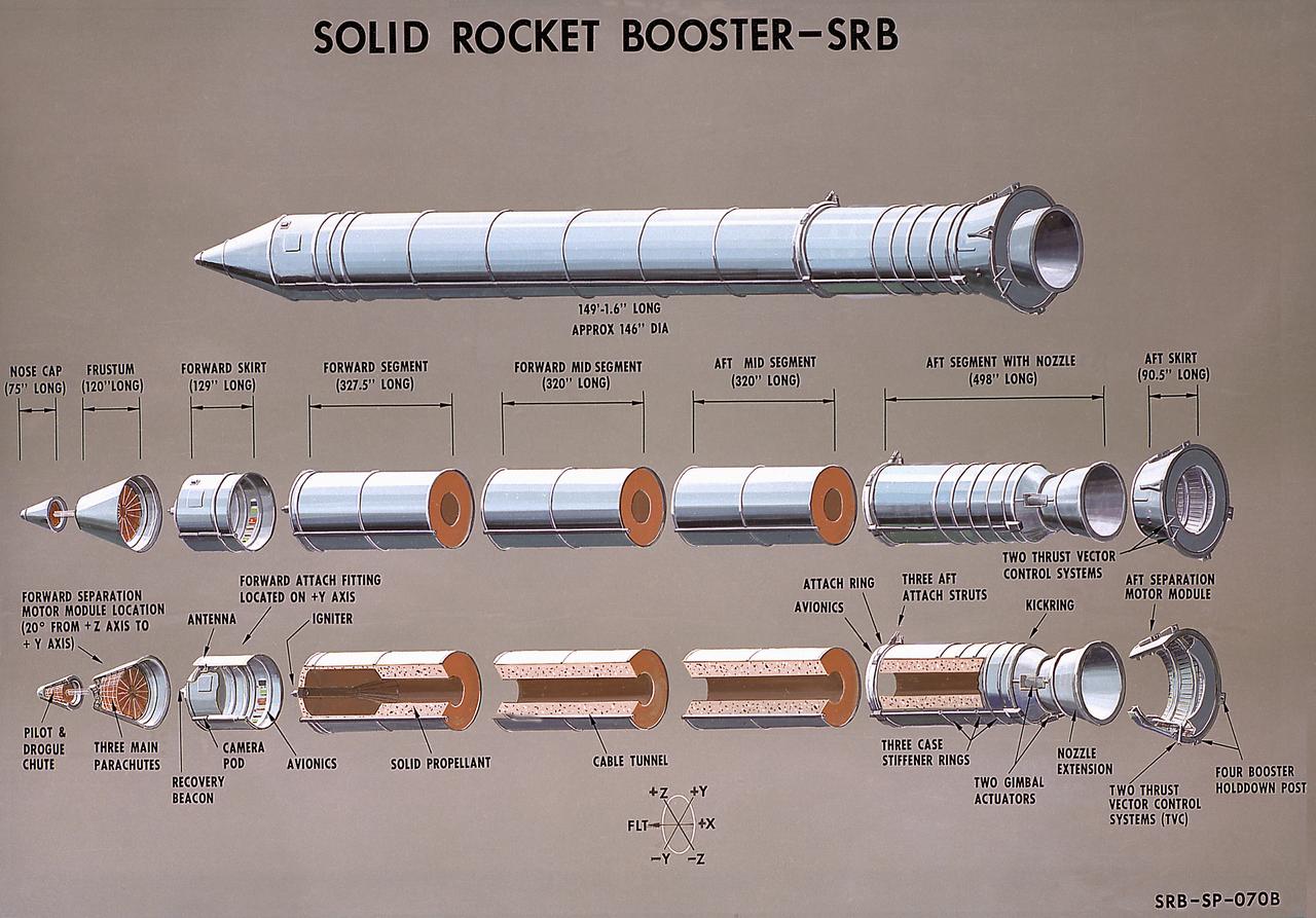
This illustration is a cutaway of the solid rocket booster (SRB) sections with callouts. The Shuttle's two SRB's are the largest solids ever built and the first designed for refurbishment and reuse. Standing nearly 150-feet high, the twin boosters provide the majority of thrust for the first two minutes of flight, about 5.8 million pounds, augmenting the Shuttle's main propulsion system during liftoff. The major design drivers for the solid rocket motors (SRM's) were high thrust and reuse. The desired thrust was achieved by using state-of-the-art solid propellant and by using a long cylindrical motor with a specific core design that allows the propellant to burn in a carefully controlled marner. At burnout, the boosters separate from the external tank and drop by parachute to the ocean for recovery and subsequent refurbishment. The boosters are designed to survive water impact at almost 60 miles per hour, maintain flotation with minimal damage, and preclude corrosion of the hardware exposed to the harsh seawater environment. Under the project management of the Marshall Space Flight Center, the SRB's are assembled and refurbished by the United Space Boosters. The SRM's are provided by the Morton Thiokol Corporation.

This is a cutaway illustration of the Space Shuttle external tank (ET) with callouts. The giant cylinder, higher than a 15-story building, with a length of 154-feet (47-meters) and a diameter of 27.5-feet (8.4-meters), is the largest single piece of the Space Shuttle. During launch, the ET also acts as a backbone for the orbiter and solid rocket boosters. Separate pressurized tank sections within the external tank hold the liquid hydrogen fuel and liquid oxygen oxidizer for the Shuttle's three main engines. During launch, the ET feeds the fuel under pressure through 17-inch (43.2-centimeter) ducts that branch off into smaller lines that feed directly into the main engines. The main engines consume 64,000 gallons (242,260 liters) of fuel each minute. Machined from aluminum alloys, the Space Shuttle's external tank is currently the only part of the launch vehicle that is not reused. After its 526,000-gallons (1,991,071 liters) of propellants are consumed during the first 8.5-minutes of flight, it is jettisoned from the orbiter and breaks up in the upper atmosphere, its pieces falling into remote ocean waters. The Marshall Space Flight Center was responsible for developing the ET.
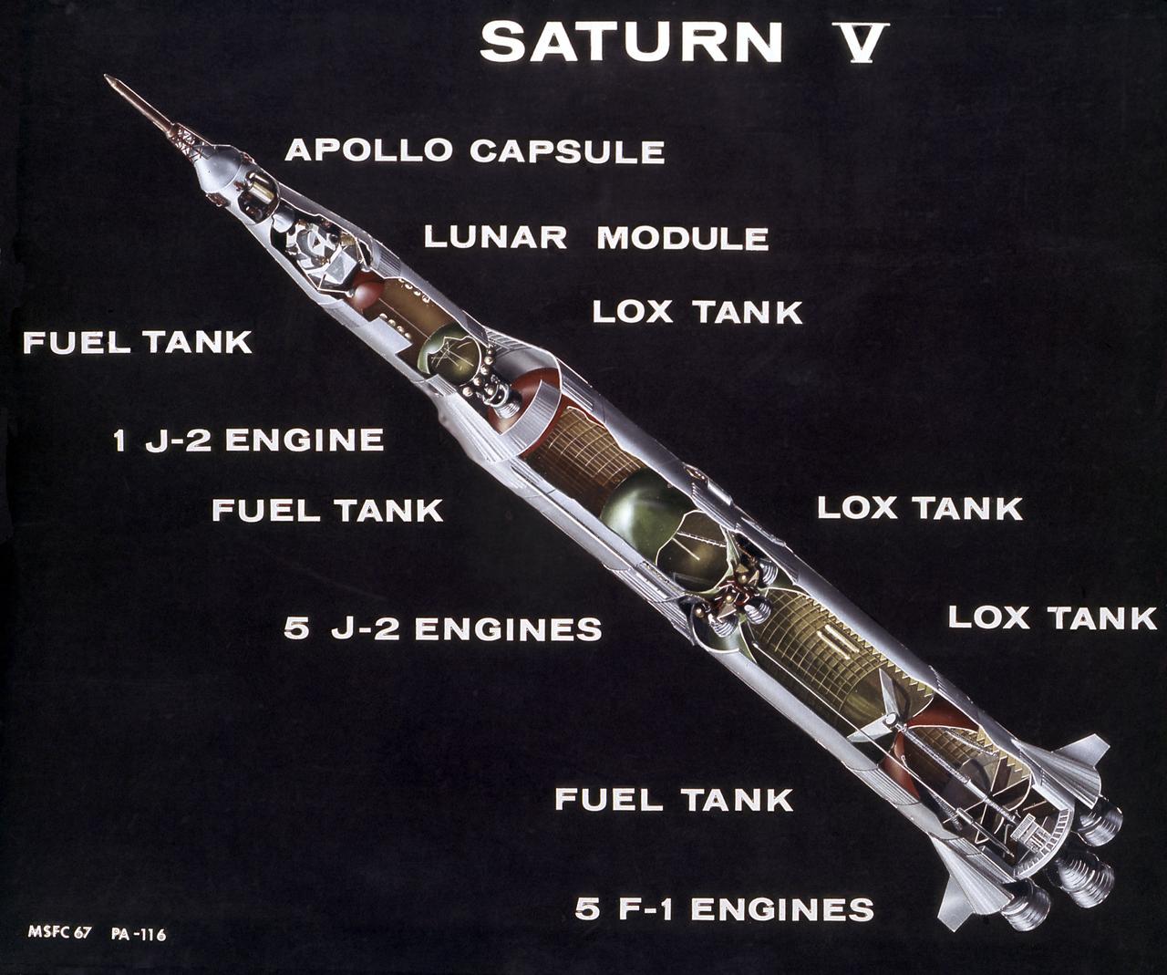
This is a cutaway illustration of the Saturn V launch vehicle with callouts of the major components. The Saturn V is the largest and most powerful launch vehicle developed in the United States. It was a three stage rocket, 363 feet in height, used for sending American astronauts to the moon and for placing the Skylab in Earth orbit. The Saturn V was designed to perform Earth orbital missions through the use of the first two stages, while all three stages were used for lunar expeditions. The S-IC stage (first stage) was powered by five F- engines, which burned kerosene and liquid oxygen to produce more than 7,500,000 pounds of thrust. The S-II (second) stage was powered by five J-2 engines, that burned liquid hydrogen and liquid oxygen and produced 1,150,000 pounds thrust. The S-IVB (third) stage used one J-2 engine, producing 230,000 pounds of thrust, with a re-start capability. The Marshall Space Flight Center and its contractors designed, developed, and assembled the Saturn V launch vehicle stages.
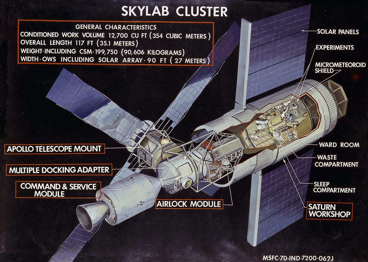
This illustration shows general characteristics of the Skylab with callouts of its major components. In an early effort to extend the use of Apollo for further applications, NASA established the Apollo Applications Program (AAP) in August of 1965. The AAP was to include long duration Earth orbital missions during which astronauts would carry out scientific, technological, and engineering experiments in space by utilizing modified Saturn launch vehicles and the Apollo spacecraft. Established in 1970, the Skylab Program was the forerurner of the AAP. The goals of the Skylab were to enrich our scientific knowledge of the Earth, the Sun, the stars, and cosmic space; to study the effects of weightlessness on living organisms, including man; to study the effects of the processing and manufacturing of materials utilizing the absence of gravity; and to conduct Earth resource observations. The Skylab also conducted 19 selected experiments submitted by high school students. Skylab's 3 different 3-man crews spent up to 84 days in Earth orbit. The Marshall Space Flight Center (MSFC) had responsibility for developing and integrating most of the major components of the Skylab: the Orbital Workshop (OWS), Airlock Module (AM), Multiple Docking Adapter (MDA), Apollo Telescope Mount (ATM), Payload Shroud (PS), and most of the experiments. MSFC was also responsible for providing the Saturn IB launch vehicles for three Apollo spacecraft and crews and a Saturn V launch vehicle for the Skylab.
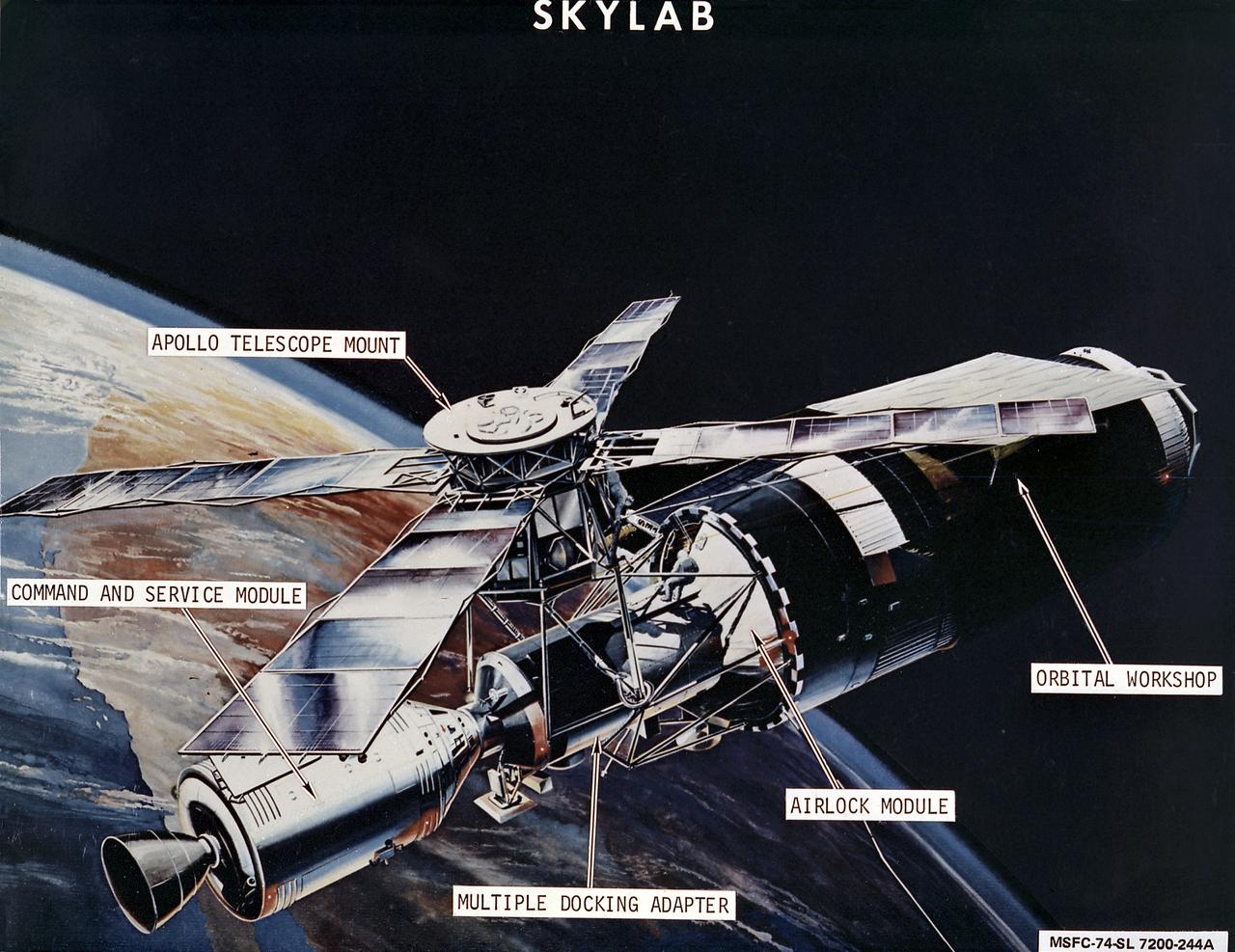
This image is an artist's concept of the Skylab in orbit with callouts of its major components. In an early effort to extend the use of Apollo for further applications, NASA established the Apollo Applications Program (AAP) in August of 1965. The AAP was to include long duration Earth orbital missions during which astronauts would carry out scientific, technological, and engineering experiments in space by utilizing modified Saturn launch vehicles and the Apollo spacecraft. Established in 1970, the Skylab Program was the forerurner of the AAP. The goals of the Skylab were to enrich our scientific knowledge of the Earth, the Sun, the stars, and cosmic space; to study the effects of weightlessness on living organisms, including man; to study the effects of the processing and manufacturing of materials utilizing the absence of gravity; and to conduct Earth resource observations. The Skylab also conducted 19 selected experiments submitted by high school students. Skylab's 3 different 3-man crews spent up to 84 days in Earth orbit. The Marshall Space Flight Center (MSFC) had responsibility for developing and integrating most of the major components of the Skylab: the Orbital Workshop (OWS), Airlock Module (AM), Multiple Docking Adapter (MDA), Apollo Telescope Mount (ATM), Payload Shroud (PS), and most of the experiments. MSFC was also responsible for providing the Saturn IB launch vehicles for three Apollo spacecraft and crews and a Saturn V launch vehicle for the Skylab.

This illustration is an orbiter cutaway view with callouts. The orbiter is both the brains and heart of the Space Transportation System (STS). About the same size and weight as a DC-9 aircraft, the orbiter contains the pressurized crew compartment (which can normally carry up to seven crew members), the huge cargo bay, and the three main engines mounted on its aft end. There are three levels to the crew cabin. Uppermost is the flight deck where the commander and the pilot control the mission. The middeck is where the gallery, toilet, sleep stations, and storage and experiment lockers are found for the basic needs of weightless daily living. Also located in the middeck is the airlock hatch into the cargo bay and space beyond. It is through this hatch and airlock that astronauts go to don their spacesuits and marned maneuvering units in preparation for extravehicular activities, more popularly known as spacewalks. The Space Shuttle's cargo bay is adaptable to hundreds of tasks. Large enough to accommodate a tour bus (60 x 15 feet or 18.3 x 4.6 meters), the cargo bay carries satellites, spacecraft, and spacelab scientific laboratories to and from Earth orbit. It is also a work station for astronauts to repair satellites, a foundation from which to erect space structures, and a hold for retrieved satellites to be returned to Earth. Thermal tile insulation and blankets (also known as the thermal protection system or TPS) cover the underbelly, bottom of the wings, and other heat-bearing surfaces of the orbiter to protect it during its fiery reentry into the Earth's atmosphere. The Shuttle's 24,000 individual tiles are made primarily of pure-sand silicate fibers, mixed with a ceramic binder. The solid rocket boosters (SRB's) are designed as an in-house Marshall Space Flight Center project, with United Space Boosters as the assembly and refurbishment contractor. The solid rocket motor (SRM) is provided by the Morton Thiokol Corporation.