
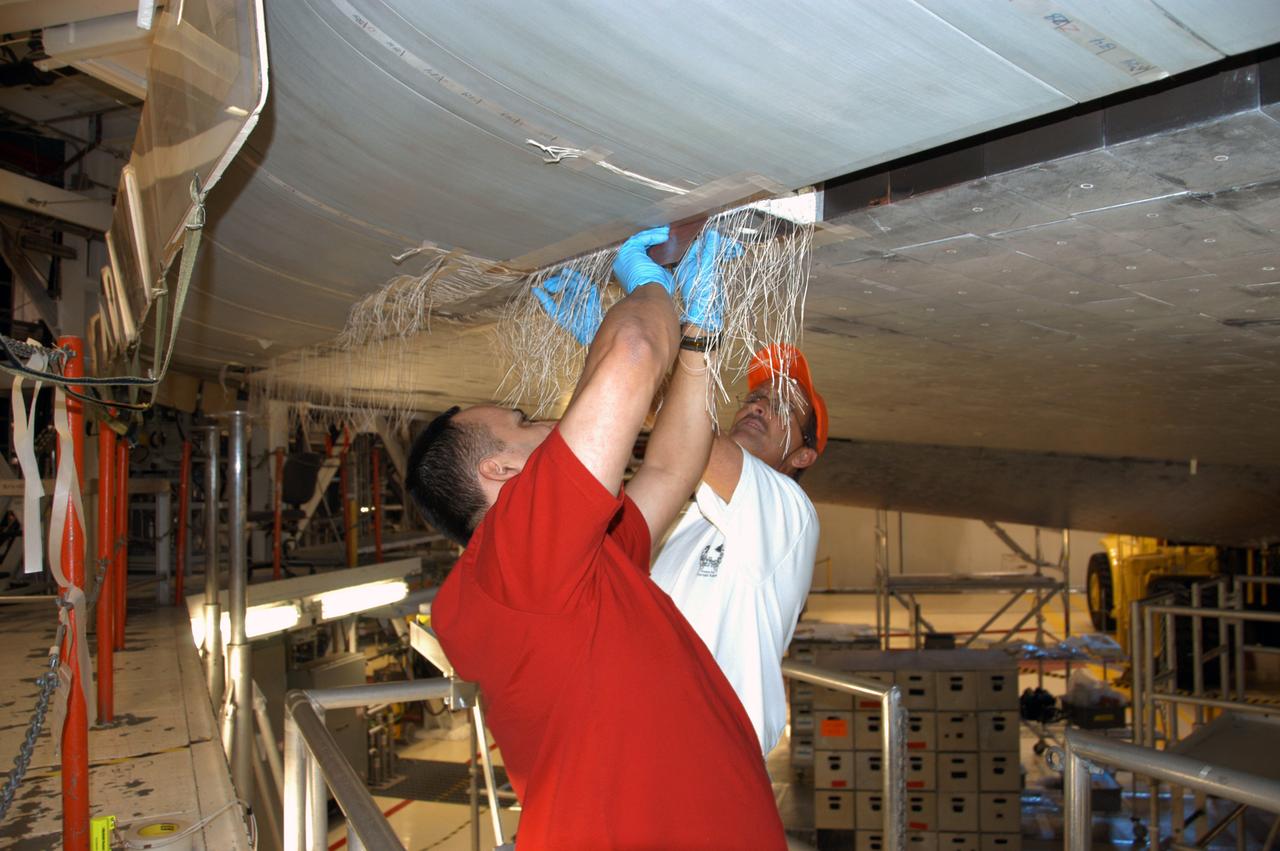
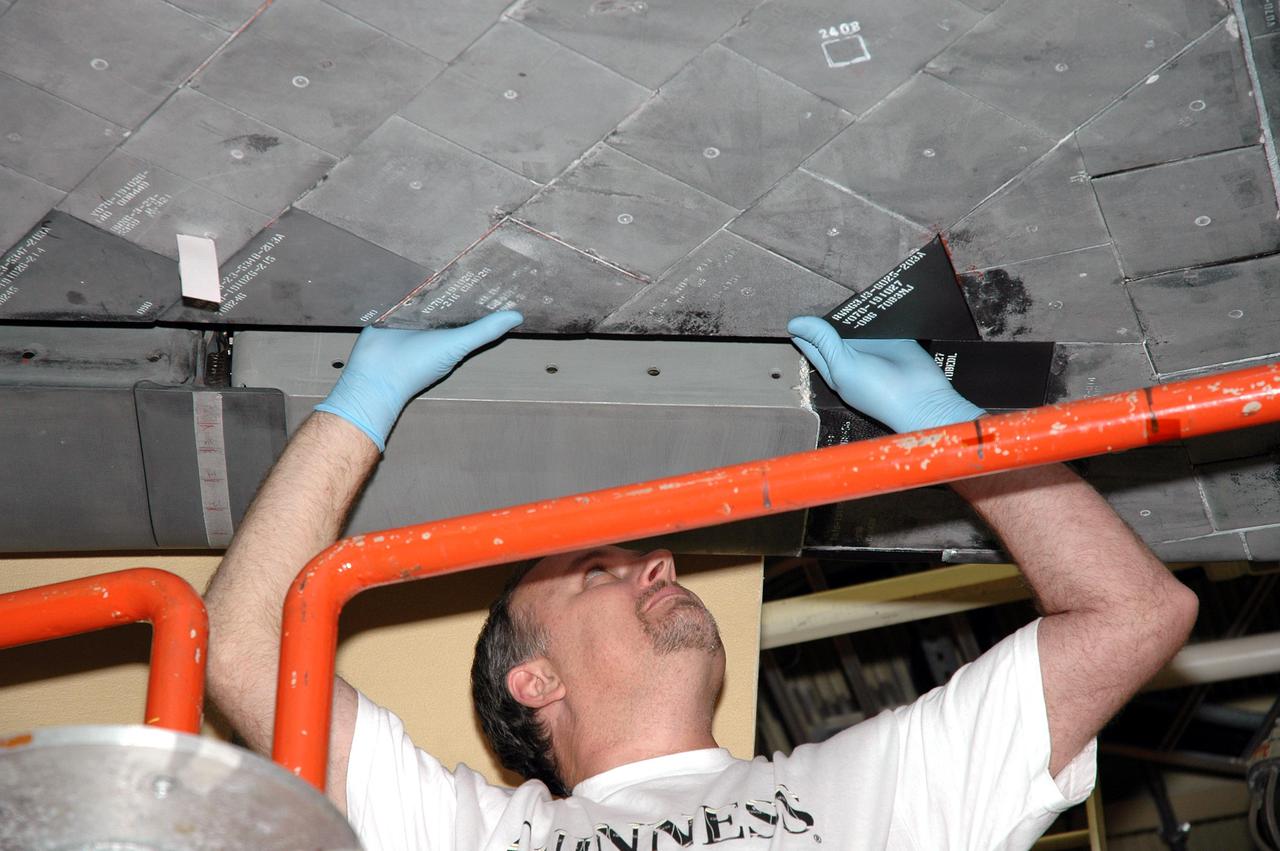
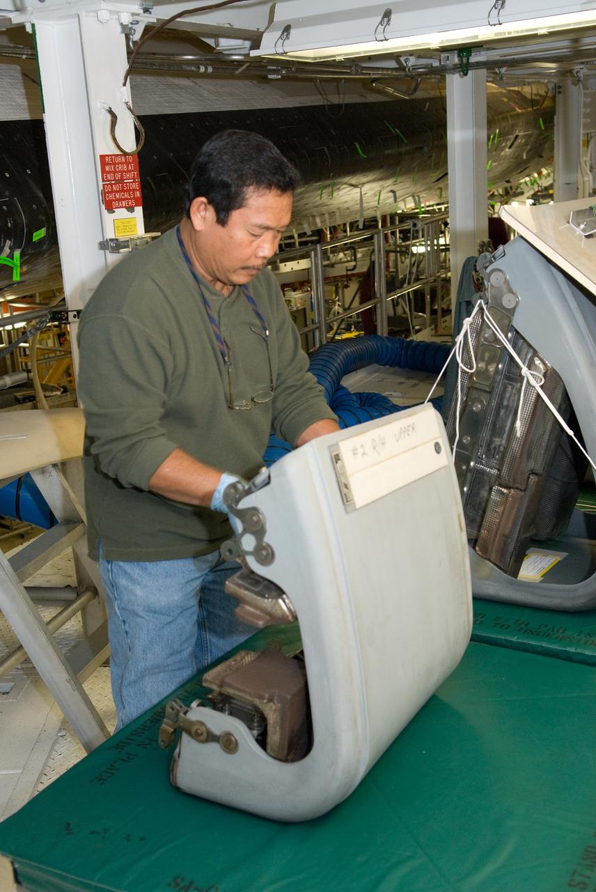
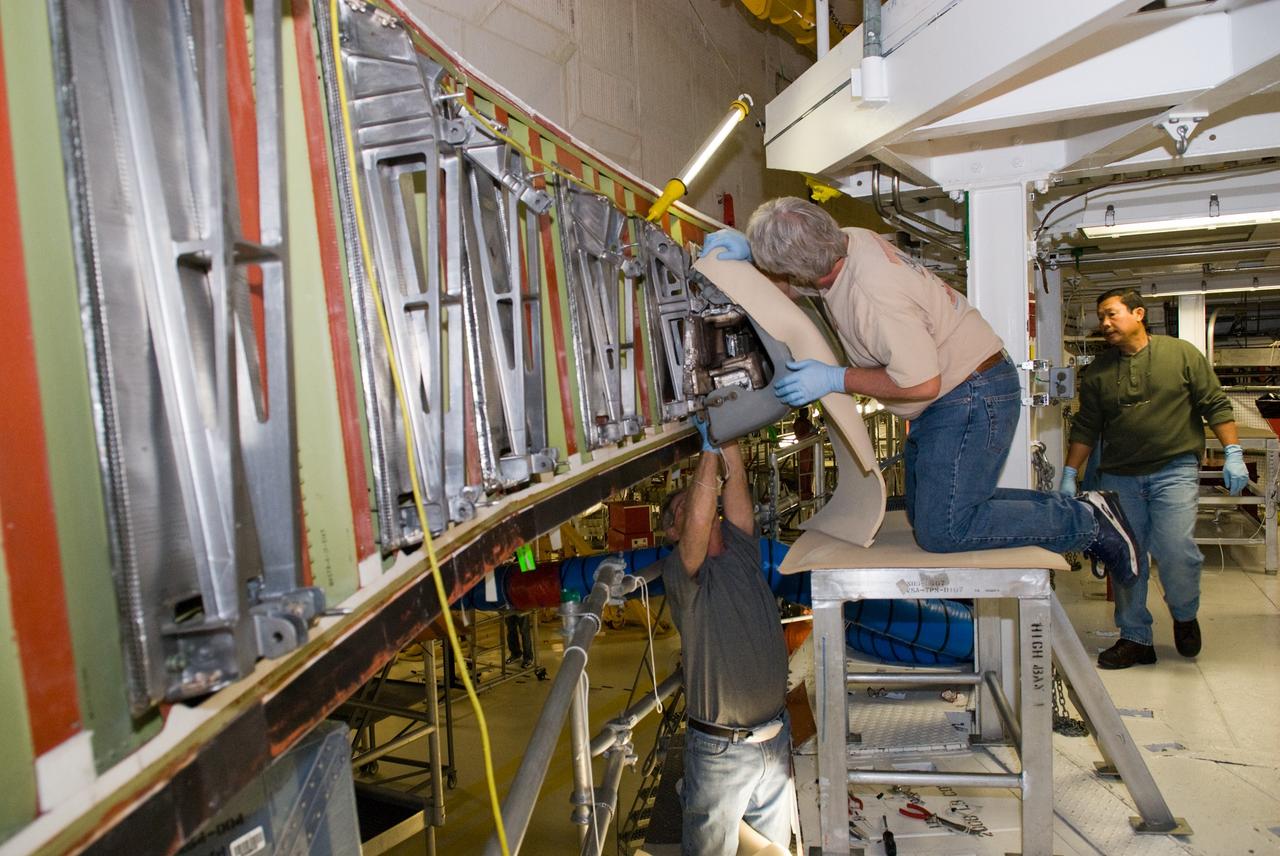
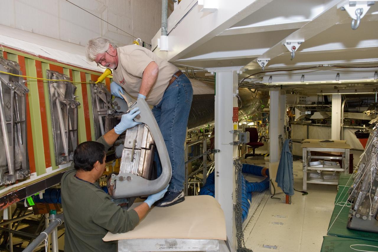
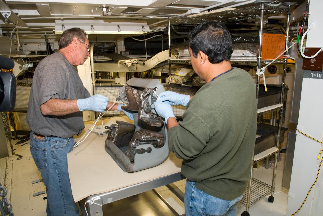
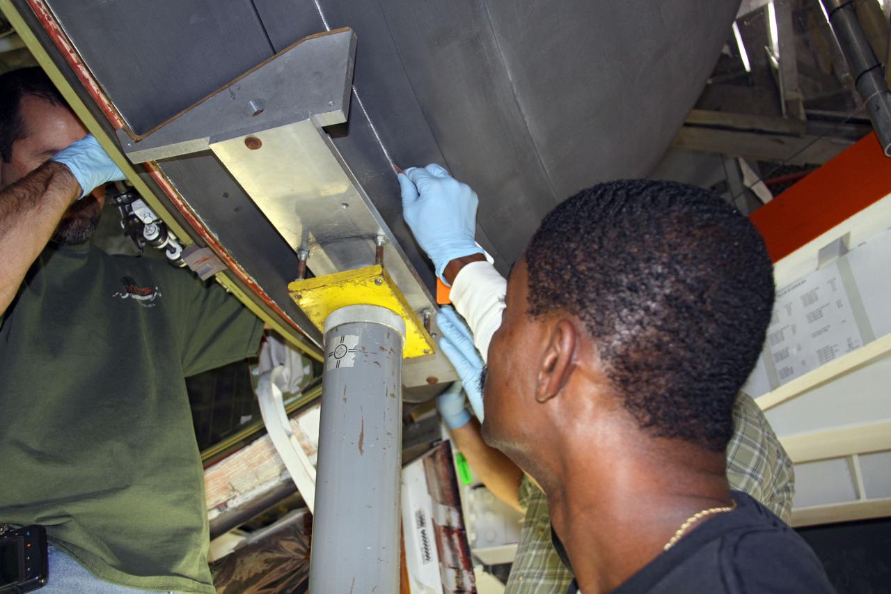
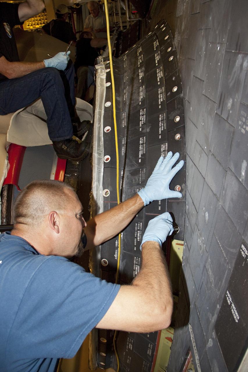
In Orbiter Processing Facility bay 2, technicians James Johnson (left) and Jesus Rodrigues install a leading edge subsystem carrier panel on the right wing of Endeavour. The orbiter is scheduled for mission STS-118, targeted for launch on June 28. The mission will be the 22nd flight to the International Space Station, carrying another starboard array, S5, for installation.
In Orbiter Processing Facility bay 2, technicians Jesus Rodrigues (left) and James Johnson install a leading edge subsystem carrier panel on the right wing of Endeavour. The orbiter is scheduled for mission STS-118, targeted for launch on June 28. The mission will be the 22nd flight to the International Space Station, carrying another starboard array, S5, for installation.
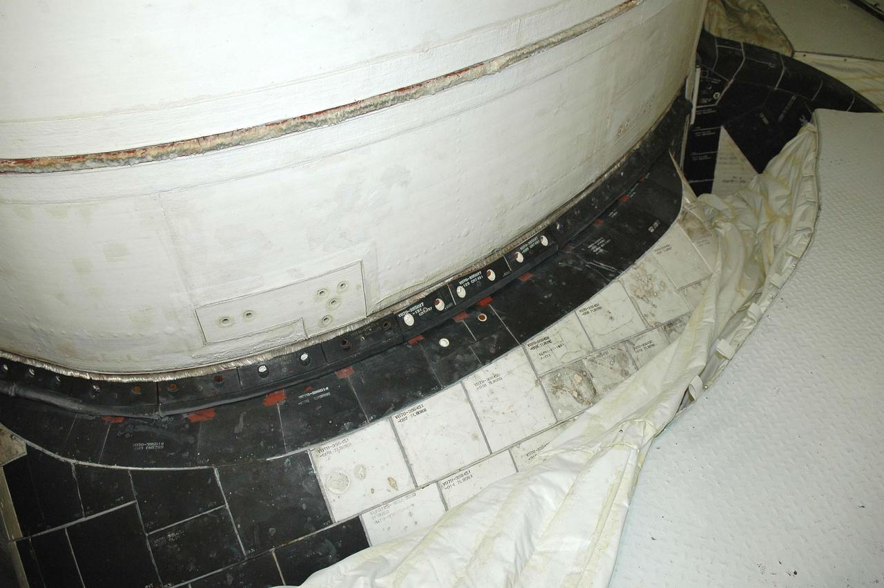
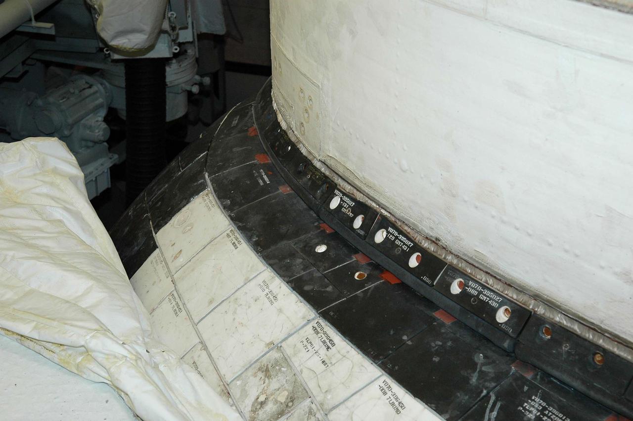
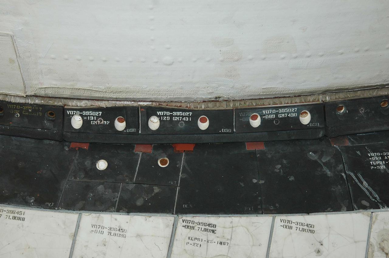
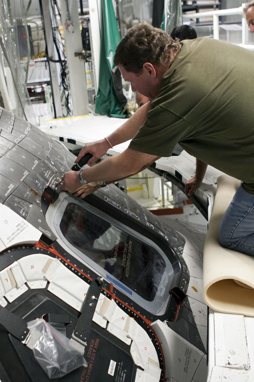
KENNEDY SPACE CENTER, FLA. - This view shows the carrier panel on the left Orbital Maneuvering System (OMS) pod on Space Shuttle Discovery. During routine closeouts at Launch Pad 39B, the cover of Discovery’s window number seven, one of the overhead crew cabin windows, fell about 65 feet and hit a carrier panel on the OMS pod, damaging several tiles. The tiles were on a single carrier panel, which fits over the area. A spare carrier panel was taken to the pad and used to replace the damaged panel. The replacement procedure took about an hour to complete. There was no delay to the launch countdown.
KENNEDY SPACE CENTER, FLA. - This view shows the carrier panel on the left Orbital Maneuvering System (OMS) pod on Space Shuttle Discovery. During routine closeouts at Launch Pad 39B, the cover of Discovery’s window number seven, one of the overhead crew cabin windows, fell about 65 feet and hit a carrier panel on the OMS pod, damaging several tiles. The tiles were on a single carrier panel, which fits over the area. A spare carrier panel was taken to the pad and used to replace the damaged panel. The replacement procedure took about an hour to complete. There was no delay to the launch countdown.
KENNEDY SPACE CENTER, FLA. - This view shows the carrier panel on the left Orbital Maneuvering System (OMS) pod on Space Shuttle Discovery. During routine closeouts at Launch Pad 39B, the cover of Discovery’s window number seven, one of the overhead crew cabin windows, fell about 65 feet and hit a carrier panel on the OMS pod, damaging several tiles. The tiles were on a single carrier panel, which fits over the area. A spare carrier panel was taken to the pad and used to replace the damaged panel. The replacement procedure took about an hour to complete. There was no delay to the launch countdown.
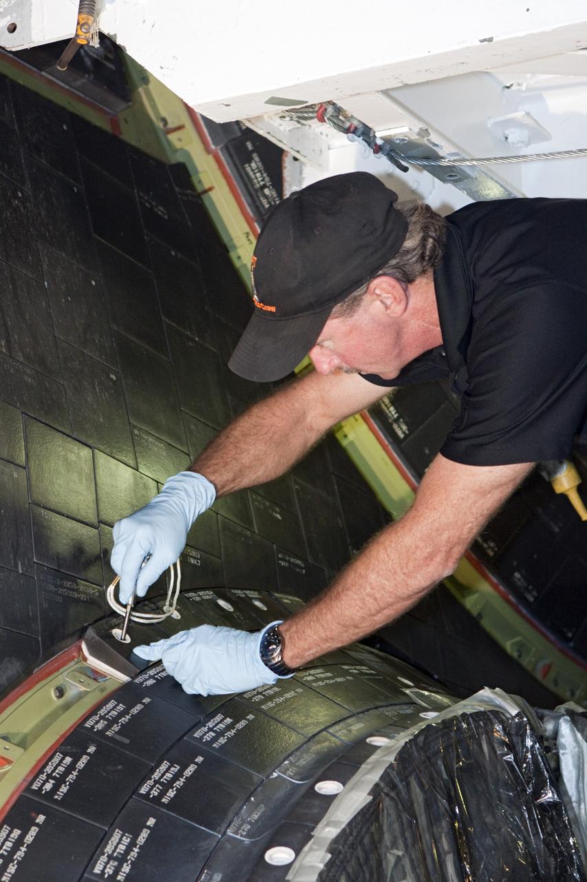
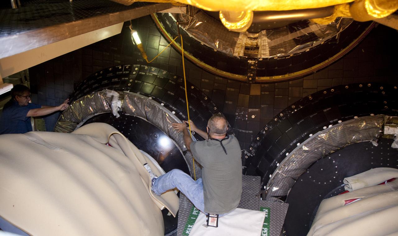
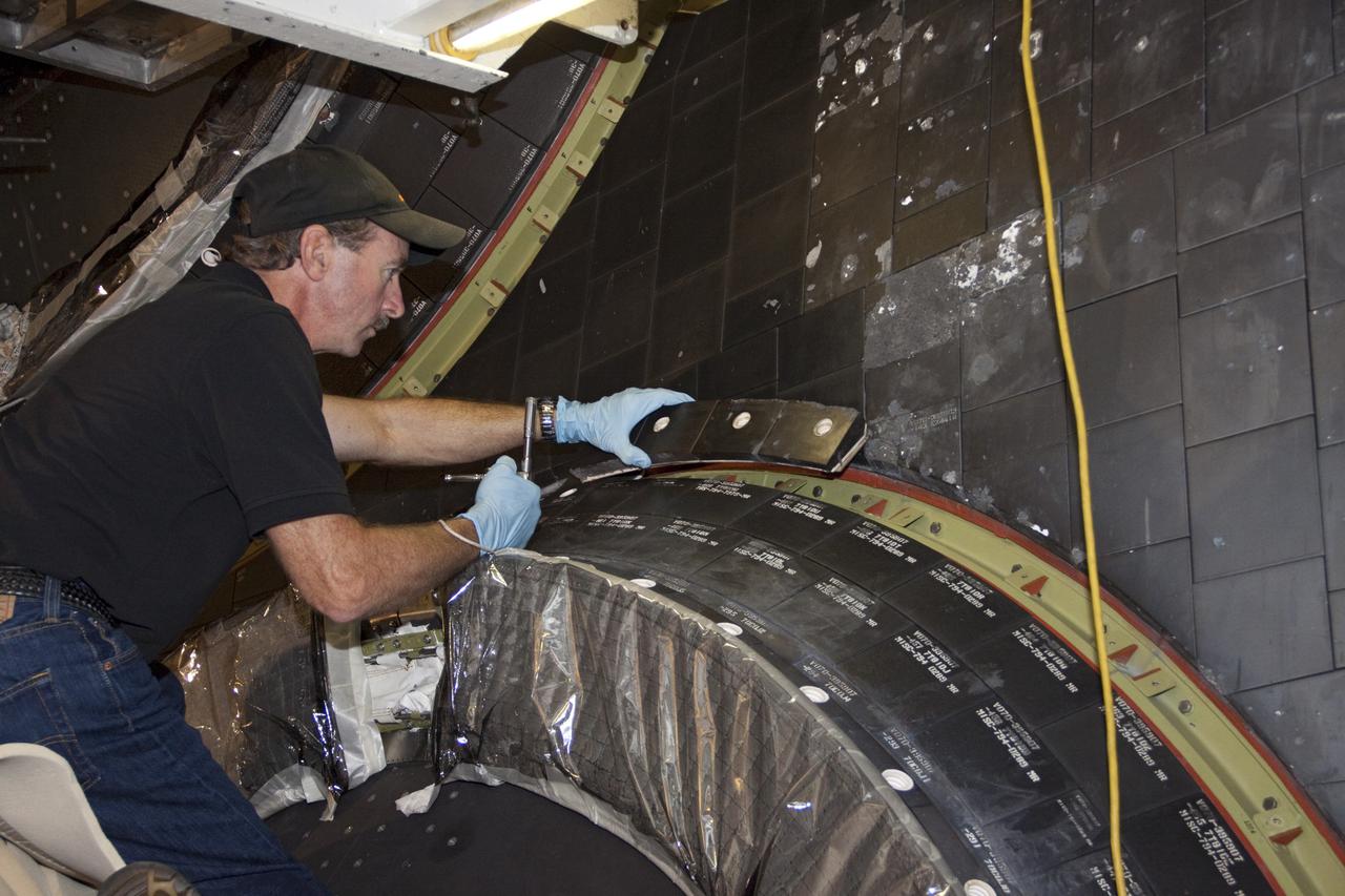
KENNEDY SPACE CENTER, FLA. - A worker in the Orbiter Processing Facility installs a new carrier panel on the orbiter Discovery. The new panel has an added thermal barrier that performs as a flow restrictor to further protect the wing leading edges. The panels fit between the Reinforced Carbon Carbon panel and the vehicle. The change is one of the safety features for return to flight. Discovery is the orbiter designated for the Return to Flight mission, STS-114. The launch window is May 12 to June 3, 2005.
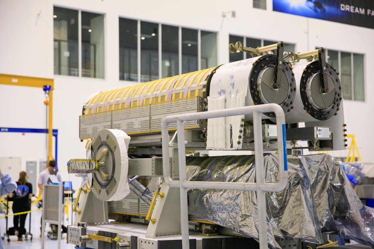
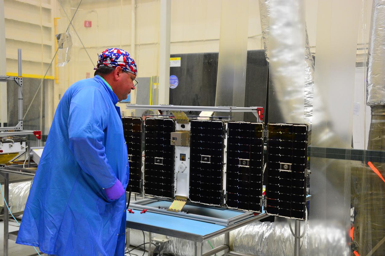
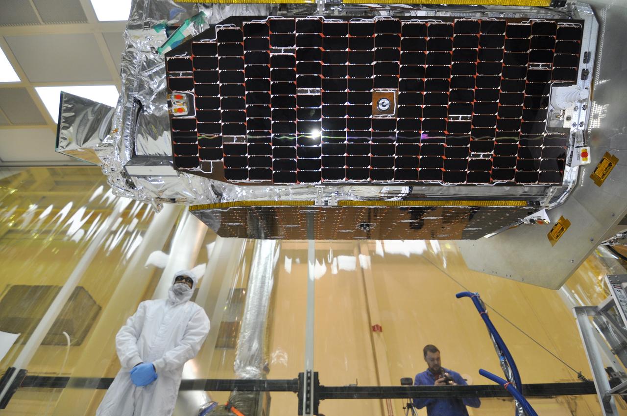
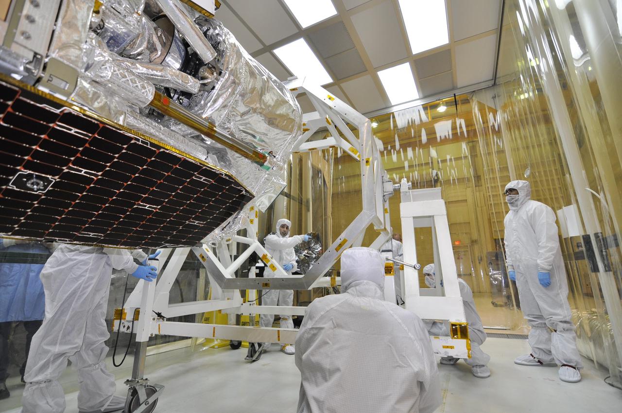
Inside the Space Station Processing Facility high bay at NASA's Kennedy Space Center in Florida, a set of International Space Station Roll Out Solar Arrays (iROSA) have been secured onto a platform on March 23, 2023. They are being prepared for delivery to the space station aboard SpaceX’s Dragon cargo carrier on the company’s 28th commercial resupply services (CRS-28) mission to the space station. iROSA is a new type of solar panel that rolls open in space and is more compact than current rigid panel designs.
KENNEDY SPACE CENTER, FLA. --The Solar Array 3 panels are part of the STS-109 flight hardware for maintenance of the Hubble Space Telescope (HST). The panels and other hardware, installed on four principle payload carriers, are being processed inside the clean room at the Vertical Processing Facility (VPF). The STS-109 launch aboard Columbia is targeted for Feb. 14, 2002, and will be the 108th flight in the Space Shuttle program
Inside the Space Station Processing Facility high bay at NASA's Kennedy Space Center in Florida, a set of International Space Station Roll Out Solar Arrays (iROSA) have been secured onto a platform on March 23, 2023. They are being prepared for delivery to the space station aboard SpaceX’s Dragon cargo carrier on the company’s 28th commercial resupply services (CRS-28) mission to the space station. iROSA is a new type of solar panel that rolls open in space and is more compact than current rigid panel designs.

KENNEDY SPACE CENTER, FLA. --The Solar Array 3 panels are part of the STS-109 flight hardware for maintenance of the Hubble Space Telescope (HST). The panels and other hardware, installed on four principle payload carriers, are being processed inside the clean room at the Vertical Processing Facility (VPF). The STS-109 launch aboard Columbia is targeted for Feb. 14, 2002, and will be the 108th flight in the Space Shuttle program
KENNEDY SPACE CENTER, FLA. - Old and new carrier panels sit side by side in the Orbiter Processing Facility. The new one in the foreground shows the added thermal barrier that performs as a flow restrictor to further protect the wing leading edges. The panels fit between the Reinforced Carbon Carbon panels and the vehicle on both the top and bottom. They are being installed on the orbiter Discovery. The change is one of the safety features for return to flight. Discovery is the orbiter designated for the Return to Flight mission, STS-114. The launch window is May 12 to June 3, 2005.

JSC2006-E-43515 (October 2006) --- Computer-generated artist's rendering of the International Space Station after flight ULF4. U.S. Orbiter delivers EXPRESS Logistics Carrier-3 (ELC-3) and EXPRESS Logistics Carrier-4 (ELC-4). Micrometeoroid Debris panels are installed on Zvezda Service Module and the Zvezda solar arrays are feathered.

The European Retrievable Carrier 1L (EURECA-1L) spacecraft, with solar array panels extended, drifts above the Earth after deployment from the payload bay of Atlantis, Orbiter Vehicle (OV) 104, during STS-46. EURECA's onboard propulsion unit will boost it to an operational altitude of 270 nautical miles.
In the Space Station Processing Facility, the overhead crane slowly moves solar panels intended for the International Space Station (ISS). The panels are the first set of U.S.-provided solar arrays and batteries for ISS, scheduled to be part of mission STS-97 in December 1999. The mission, fifth in the U.S. flights for construction of ISS, will build and enhance the capabilities of the Space Station. It will deliver the solar panels as well as radiators to provide cooling. The Shuttle will spend 5 days docked to the station, which at that time will be staffed by the first station crew. Two space walks will be conducted to complete assembly operations while the arrays are attached and unfurled. A communications system for voice and telemetry also will be installed. At the left of the crane and panels is the Multipurpose Logistics Module (MPLM), the Leonardo A reusable logistics carrier, the MPLM is scheduled to be launched on Space Shuttle Mission STS-100, targeted for April 2000
Outside the Space Station Processing Facility high bay at NASA's Kennedy Space Center in Florida, a technician uses a Hyster forklift to carry the Roll-Out Solar Array, or ROSA, to the loading dock. ROSA will be delivered to the International Space Station aboard the SpaceX Dragon cargo carrier on the company’s 11th commercial resupply services mission to the space station. ROSA is a new type of solar panel that rolls open in space and is more compact than current rigid panel designs. The ROSA investigation will test deployment and retraction, shape changes when the Earth blocks the sun, and other physical challenges to determine the array's strength and durability.
Inside the Space Station Processing Facility high bay at NASA's Kennedy Space Center in Florida, technicians assist as a crane is used to lower a set of International Space Station Roll Out Solar Arrays (iROSA) onto a platform on March 23, 2023. They are being prepared for delivery to the space station aboard SpaceX’s Dragon cargo carrier on the company’s 28th commercial resupply services (CRS-28) mission to the space station. iROSA is a new type of solar panel that rolls open in space and is more compact than current rigid panel designs.
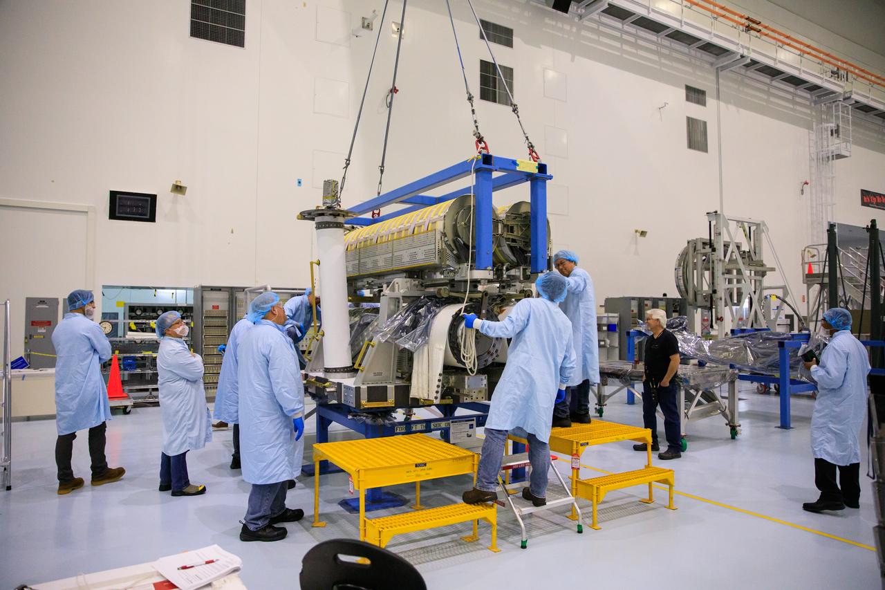
Inside the Space Station Processing Facility high bay at NASA's Kennedy Space Center in Florida, technicians assist as a crane is used to lower a set of International Space Station Roll Out Solar Arrays (iROSA) onto a platform on March 23, 2023. They are being prepared for delivery to the space station aboard SpaceX’s Dragon cargo carrier on the company’s 28th commercial resupply services (CRS-28) mission to the space station. iROSA is a new type of solar panel that rolls open in space and is more compact than current rigid panel designs.
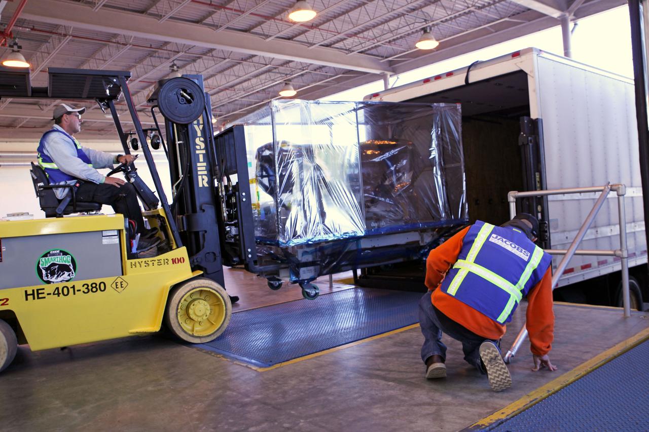
At the loading dock outside the Space Station Processing Facility high bay at NASA's Kennedy Space Center in Florida, a technician uses a Hyster forklift to load the Roll-Out Solar Array, or ROSA, into a truck. ROSA will be delivered to the International Space Station aboard the SpaceX Dragon cargo carrier on the company’s 11th commercial resupply services mission to the space station. ROSA is a new type of solar panel that rolls open in space and is more compact than current rigid panel designs. The ROSA investigation will test deployment and retraction, shape changes when the Earth blocks the sun, and other physical challenges to determine the array's strength and durability.

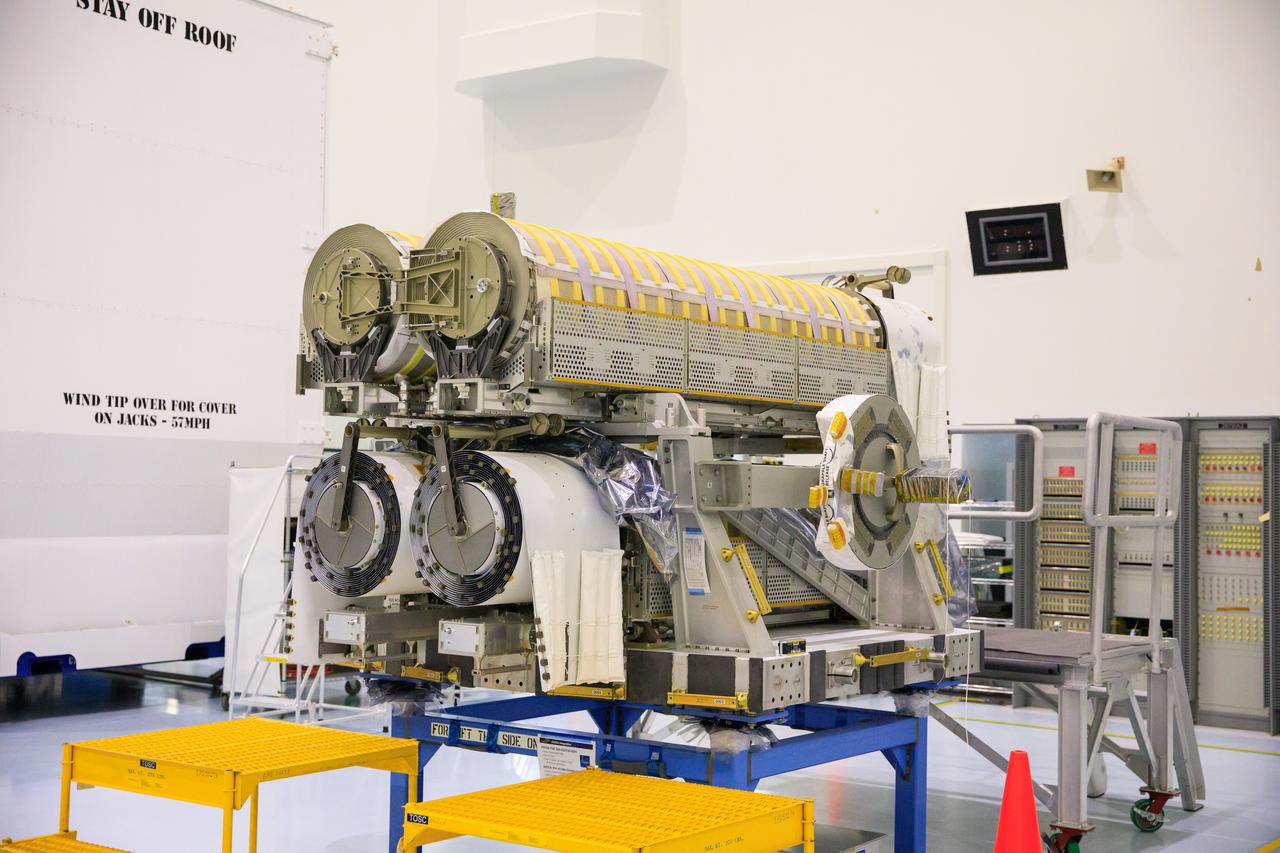
Inside the Space Station Processing Facility high bay at NASA's Kennedy Space Center in Florida, technicians assist as a crane is used to lift and stack the third set of two International Space Station Roll Out Solar Arrays (iROSA) onto a platform on March 23, 2023. They are being prepared for delivery to the space station aboard SpaceX’s Dragon cargo carrier on the company’s 28th commercial resupply services (CRS-28) mission to the space station. iROSA is a new type of solar panel that rolls open in space and is more compact than current rigid panel designs.
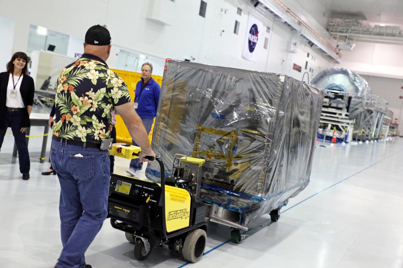
Inside the Space Station Processing Facility high bay at NASA's Kennedy Space Center in Florida, the Roll-Out Solar Array, or ROSA, is being prepared for transfer out of the high bay. ROSA will be delivered to the International Space Station aboard the SpaceX Dragon cargo carrier on the company’s 11th commercial resupply services mission to the space station. ROSA is a new type of solar panel that rolls open in space and is more compact than current rigid panel designs. The ROSA investigation will test deployment and retraction, shape changes when the Earth blocks the sun, and other physical challenges to determine the array's strength and durability.
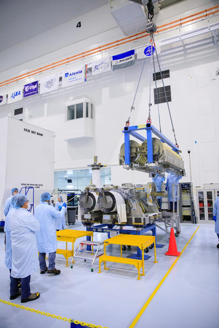
Inside the Space Station Processing Facility high bay at NASA's Kennedy Space Center in Florida, technicians monitor the progress as a crane is used to lift and stack the third set of two International Space Station Roll Out Solar Arrays (iROSA) onto a platform on March 23, 2023. They are being prepared for delivery to the space station aboard SpaceX’s Dragon cargo carrier on the company’s 28th commercial resupply services (CRS-28) mission to the space station. iROSA is a new type of solar panel that rolls open in space and is more compact than current rigid panel designs.
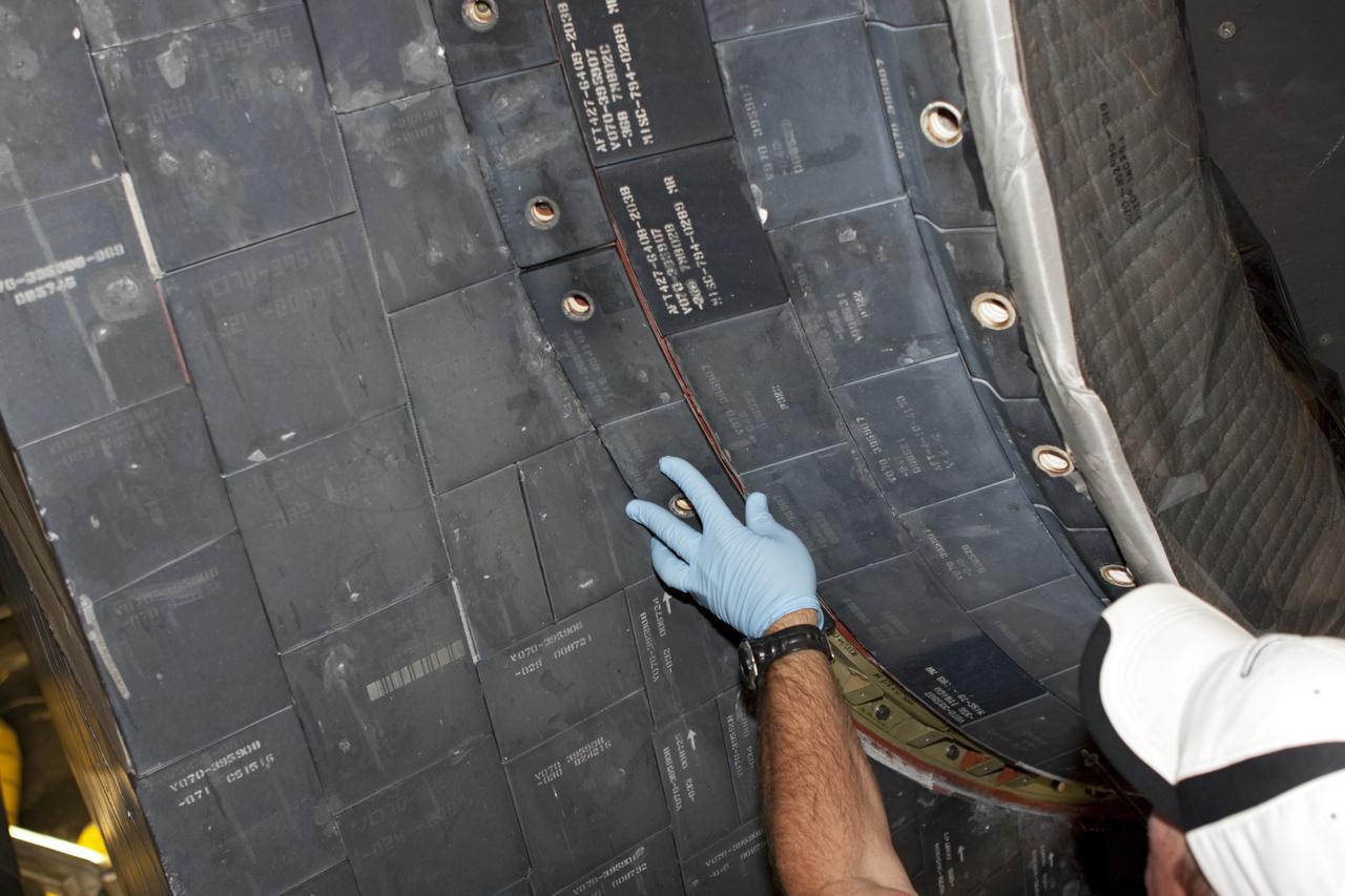
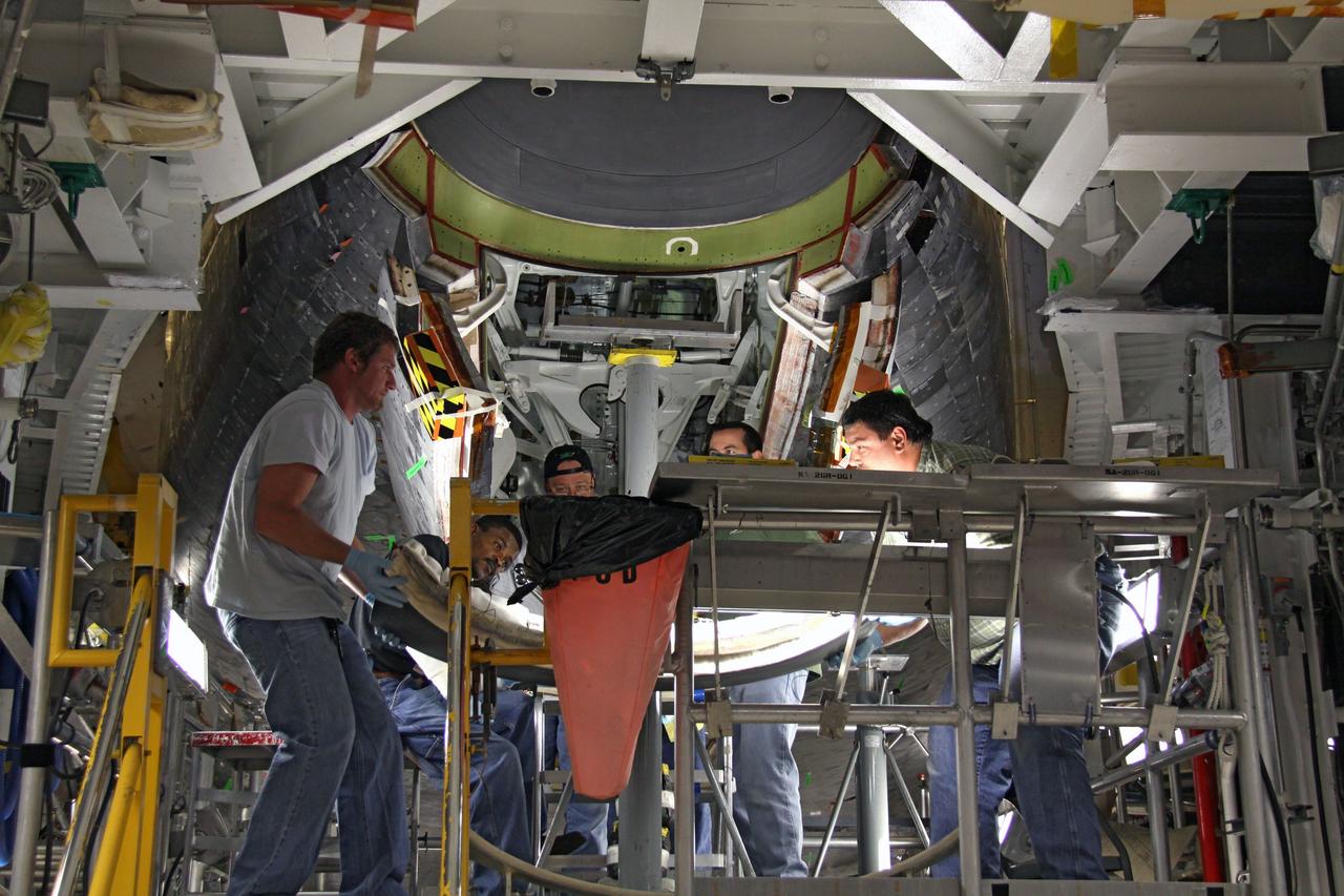
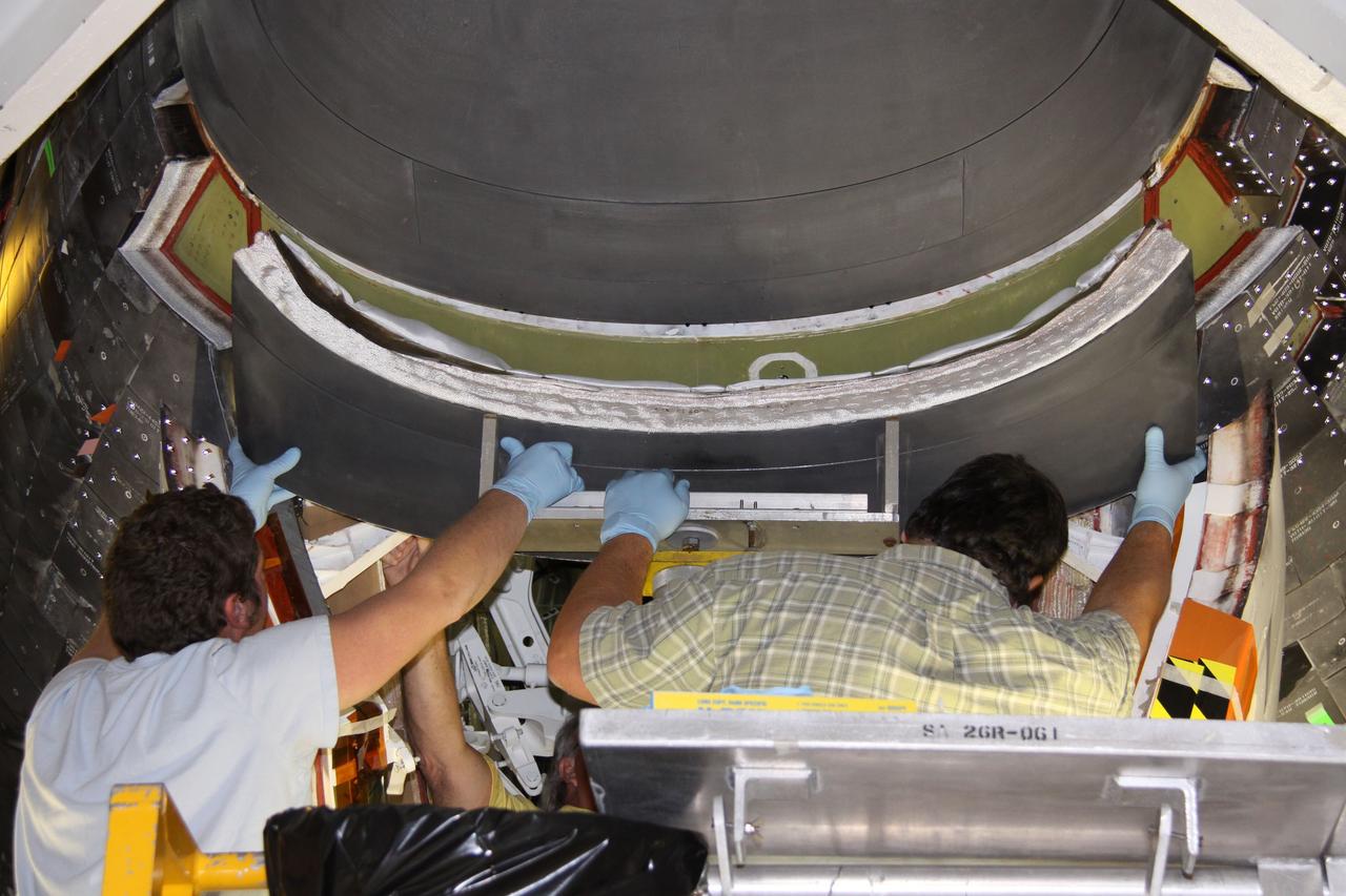
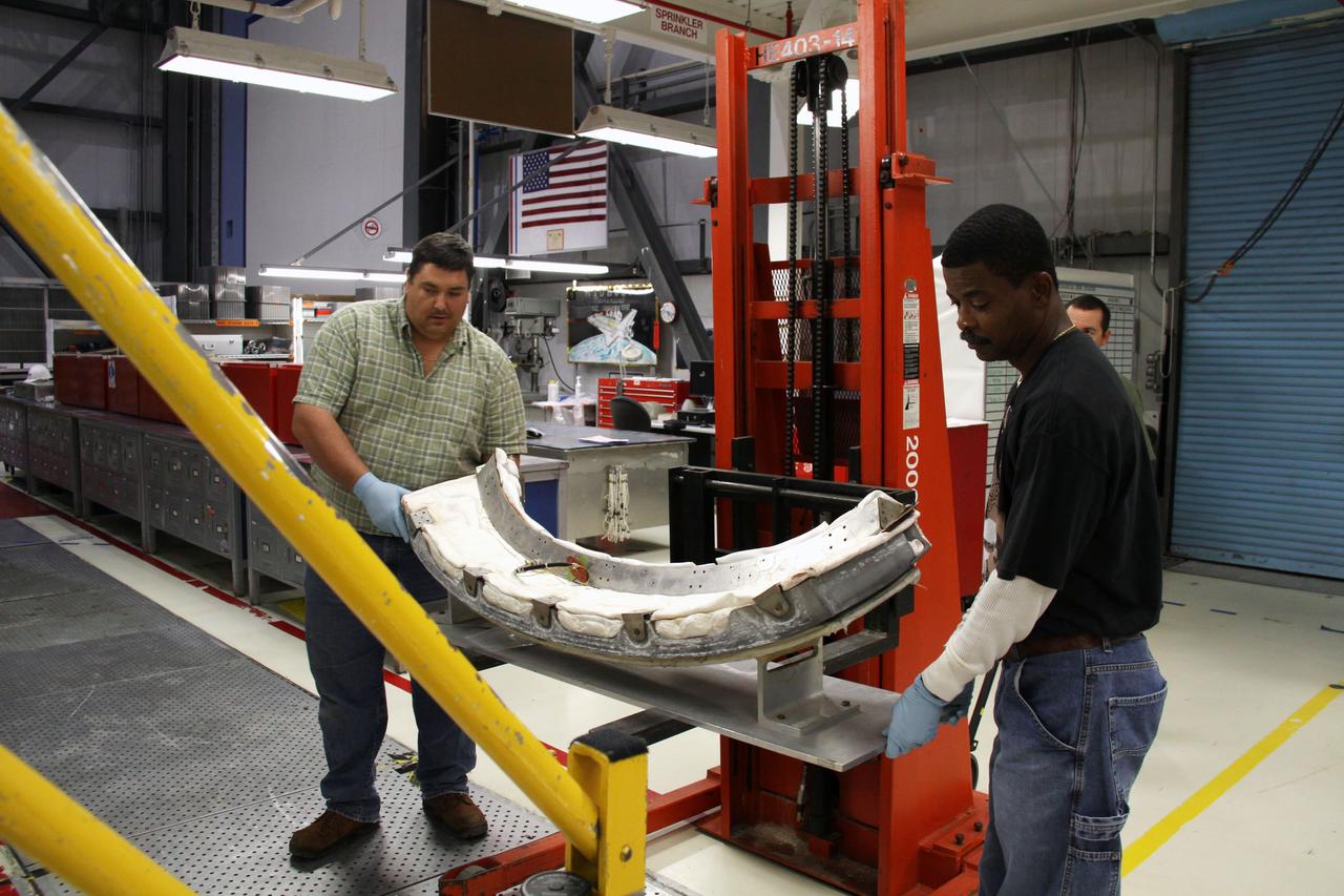
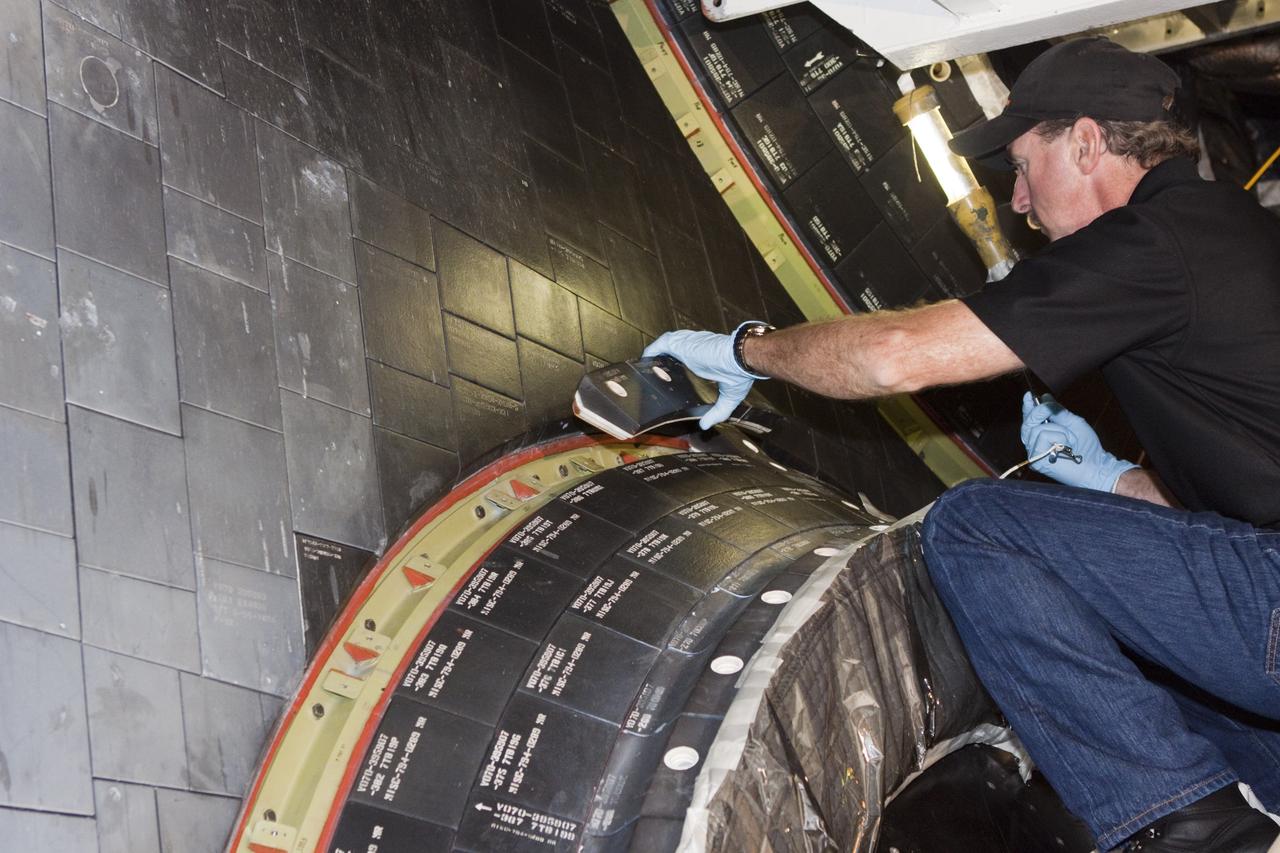
CAPE CANAVERAL, Fla. - In Orbiter Processing Facility-1 at NASA's Kennedy Space Center in Florida, a United Space Alliance technician inspects a reinforced carbon carbon panel, or RCC panel, removed from a wing leading edge of space shuttle Atlantis. Inspection and maintenance of the RCC panels and the wing leading edge are standard procedure between shuttle missions. The RCC panels, components of the shuttle's thermal protection system, are placed in protective coverings while the structural edge of the wing -- the orange and green area behind the panels -- undergoes spar corrosion inspection to verify the structural integrity of the wing. Atlantis is next slated to deliver an Integrated Cargo Carrier and Russian-built Mini Research Module to the International Space Station on the STS-132 mission. The second in a series of new pressurized components for Russia, the module will be permanently attached to the Zarya module. Three spacewalks are planned to store spare components outside the station, including six spare batteries, a boom assembly for the Ku-band antenna and spares for the Canadian Dextre robotic arm extension. A radiator, airlock and European robotic arm for the Russian Multi-purpose Laboratory Module also are payloads on the flight. Launch is targeted for May 14, 2010. Photo credit: NASA/Glenn Benson
CAPE CANAVERAL, Fla. - In Orbiter Processing Facility-1 at NASA's Kennedy Space Center in Florida, United Space Alliance technicians cover a reinforced carbon carbon panel, or RCC panel, removed from a wing leading edge of space shuttle Atlantis. Inspection and maintenance of the RCC panels and the wing leading edge are standard procedure between shuttle missions. The RCC panels, components of the shuttle's thermal protection system, are placed in protective coverings while the structural edge of the wing -- the orange and green area behind the panels -- undergoes spar corrosion inspection to verify the structural integrity of the wing. Atlantis is next slated to deliver an Integrated Cargo Carrier and Russian-built Mini Research Module to the International Space Station on the STS-132 mission. The second in a series of new pressurized components for Russia, the module will be permanently attached to the Zarya module. Three spacewalks are planned to store spare components outside the station, including six spare batteries, a boom assembly for the Ku-band antenna and spares for the Canadian Dextre robotic arm extension. A radiator, airlock and European robotic arm for the Russian Multi-purpose Laboratory Module also are payloads on the flight. Launch is targeted for May 14, 2010. Photo credit: NASA/Glenn Benson
CAPE CANAVERAL, Fla. - In Orbiter Processing Facility-1 at NASA's Kennedy Space Center in Florida, United Space Alliance technicians remove a reinforced carbon carbon panel, or RCC panel, from a wing leading edge of space shuttle Atlantis. Inspection and maintenance of the RCC panels and the wing leading edge are standard procedure between shuttle missions. The RCC panels, components of the shuttle's thermal protection system, are placed in protective coverings while the structural edge of the wing -- the orange and green area behind the panels -- undergoes spar corrosion inspection to verify the structural integrity of the wing. Atlantis is next slated to deliver an Integrated Cargo Carrier and Russian-built Mini Research Module to the International Space Station on the STS-132 mission. The second in a series of new pressurized components for Russia, the module will be permanently attached to the Zarya module. Three spacewalks are planned to store spare components outside the station, including six spare batteries, a boom assembly for the Ku-band antenna and spares for the Canadian Dextre robotic arm extension. A radiator, airlock and European robotic arm for the Russian Multi-purpose Laboratory Module also are payloads on the flight. Launch is targeted for May 14, 2010. Photo credit: NASA/Glenn Benson
CAPE CANAVERAL, Fla. - In Orbiter Processing Facility-1 at NASA's Kennedy Space Center in Florida, United Space Alliance technicians prepare to cover a reinforced carbon carbon panel, or RCC panel, removed from a wing leading edge of space shuttle Atlantis. Inspection and maintenance of the RCC panels and the wing leading edge are standard procedure between shuttle missions. The RCC panels, components of the shuttle's thermal protection system, are placed in protective coverings while the structural edge of the wing -- the orange and green area behind the panels -- undergoes spar corrosion inspection to verify the structural integrity of the wing. Atlantis is next slated to deliver an Integrated Cargo Carrier and Russian-built Mini Research Module to the International Space Station on the STS-132 mission. The second in a series of new pressurized components for Russia, the module will be permanently attached to the Zarya module. Three spacewalks are planned to store spare components outside the station, including six spare batteries, a boom assembly for the Ku-band antenna and spares for the Canadian Dextre robotic arm extension. A radiator, airlock and European robotic arm for the Russian Multi-purpose Laboratory Module also are payloads on the flight. Launch is targeted for May 14, 2010. Photo credit: NASA/Glenn Benson
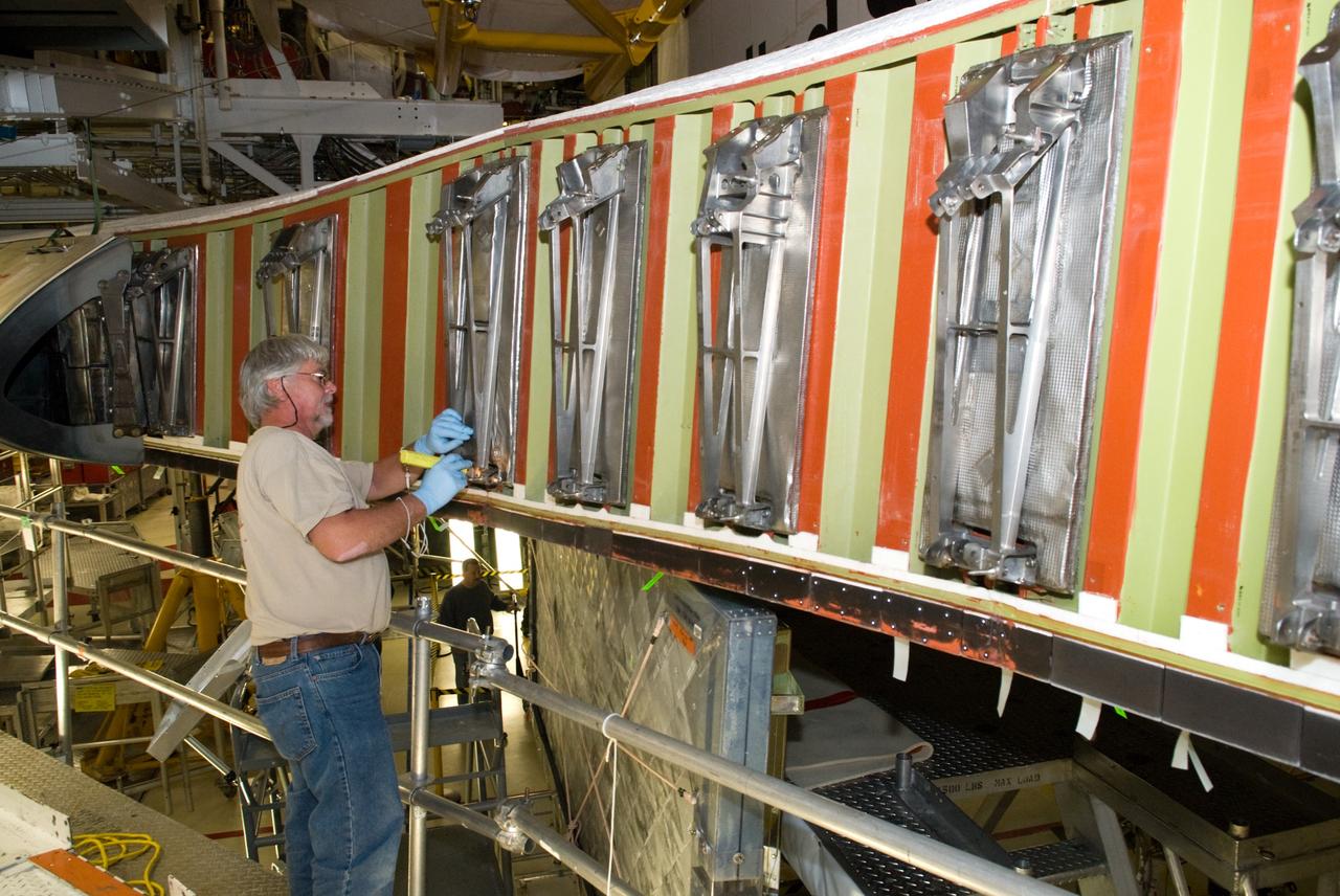
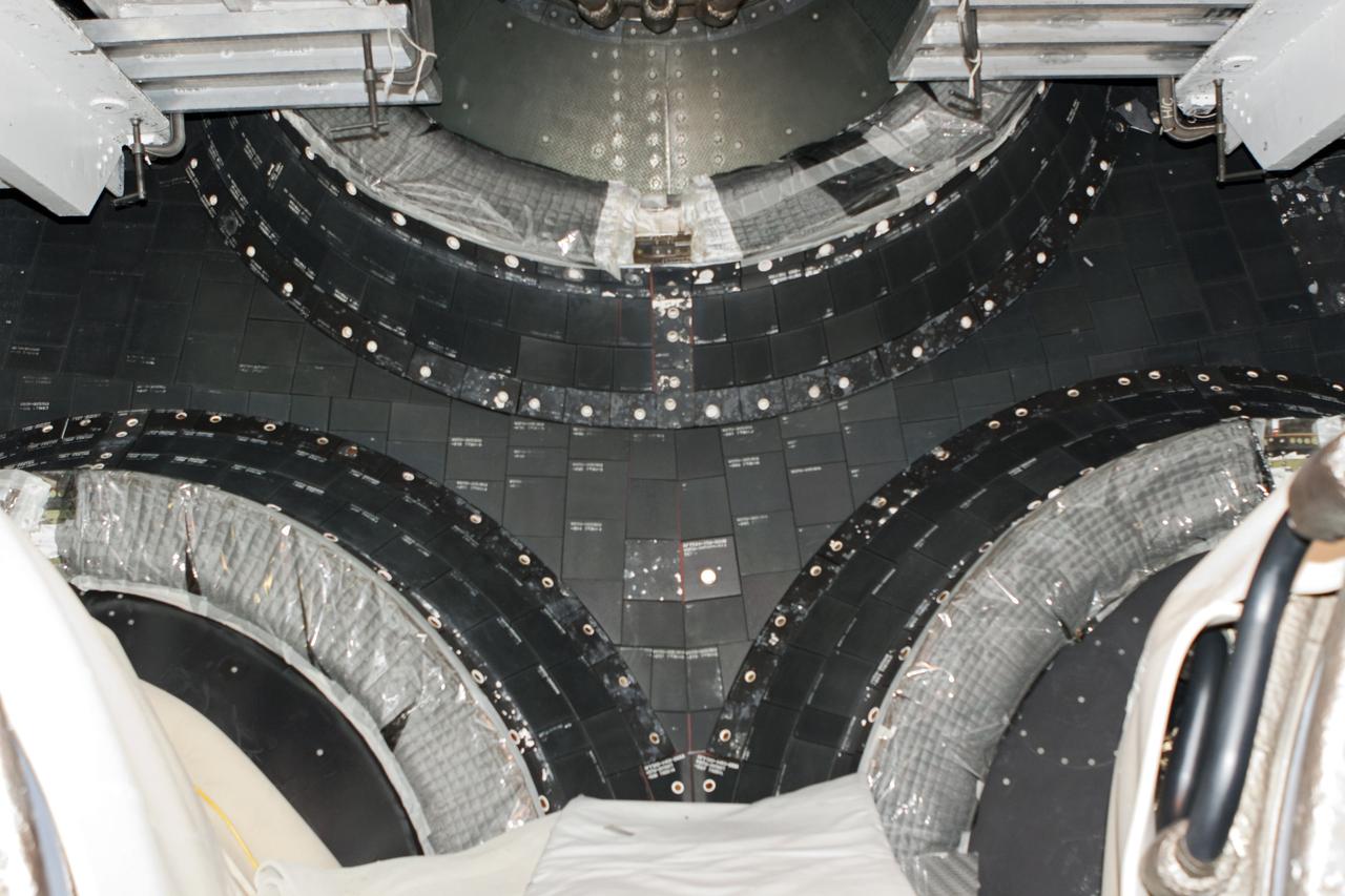
CAPE CANAVERAL, Fla. - In Orbiter Processing Facility-1 at NASA's Kennedy Space Center in Florida, a United Space Alliance technician inspects a wing leading edge of space shuttle Atlantis following removal of the reinforced carbon carbon panels, or RCC panels. Inspection and maintenance of the RCC panels and the wing leading edge are standard procedure between shuttle missions. The RCC panels, components of the shuttle's thermal protection system, are placed in protective coverings while the structural edge of the wing -- the orange and green area behind the panels -- undergoes spar corrosion inspection to verify the structural integrity of the wing. Atlantis is next slated to deliver an Integrated Cargo Carrier and Russian-built Mini Research Module to the International Space Station on the STS-132 mission. The second in a series of new pressurized components for Russia, the module will be permanently attached to the Zarya module. Three spacewalks are planned to store spare components outside the station, including six spare batteries, a boom assembly for the Ku-band antenna and spares for the Canadian Dextre robotic arm extension. A radiator, airlock and European robotic arm for the Russian Multi-purpose Laboratory Module also are payloads on the flight. Launch is targeted for May 14, 2010. Photo credit: NASA/Glenn Benson
KENNEDY SPACE CENTER, FLA. -- Workers in the Vertical Processing Facility look over the Axial Science Instrument Protective Enclosure (ASIPE), which will house the Advanced Camera for Surveys (ACS), part of the STS-109 flight hardware for maintenance of the Hubble Space Telescope (HST). The Solar Array 3 panels behind them, and other HST hardware, are installed on four principle payload carriers. The STS-109 launch aboard Columbia is targeted for Feb. 14, 2002, and will be the 108th flight in the Space Shuttle program

KENNEDY SPACE CENTER, FLA. -- Workers in the Vertical Processing Facility look over the Axial Science Instrument Protective Enclosure (ASIPE), which will house the Advanced Camera for Surveys (ACS), part of the STS-109 flight hardware for maintenance of the Hubble Space Telescope (HST). The Solar Array 3 panels behind them, and other HST hardware, are installed on four principle payload carriers. The STS-109 launch aboard Columbia is targeted for Feb. 14, 2002, and will be the 108th flight in the Space Shuttle program
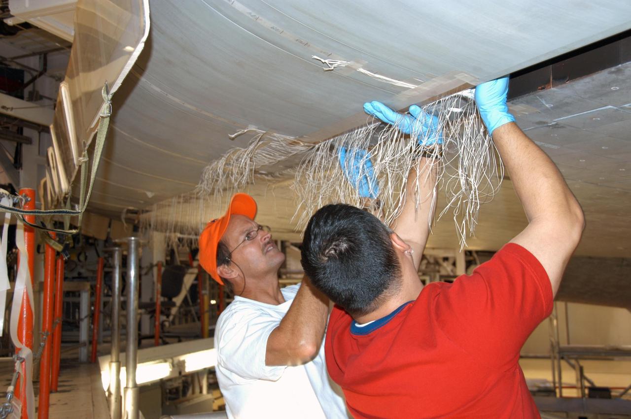
KENNEDY SPACE CENTER, FLA. -- In Orbiter Processing Facility bay 2, technicians James Johnson (left) and Jesus Rodrigues install a leading edge subsystem carrier panel on the right wing of Endeavour. The orbiter is scheduled for mission STS-118, targeted for launch on June 28. The mission will be the 22nd flight to the International Space Station, carrying another starboard array, S5, for installation. Photo credit: NASA/George Shelton
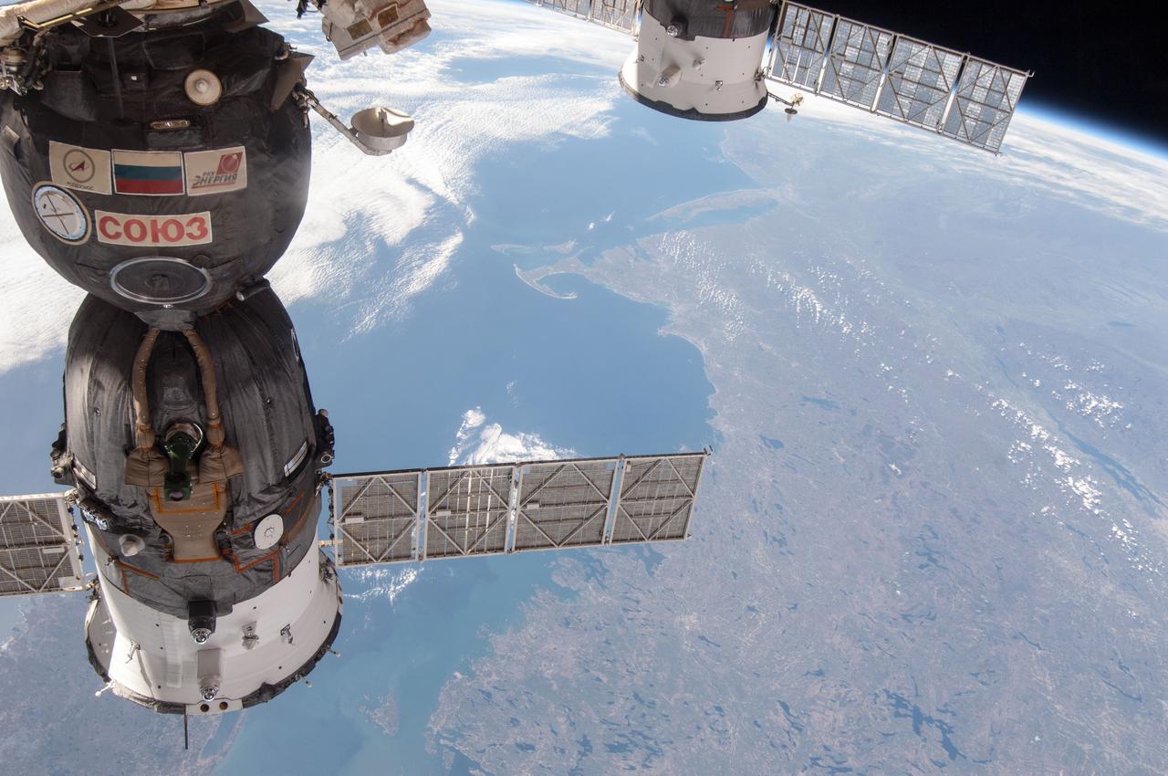
ISS035-E-034210 (4 May 2013) --- One of the Expedition 35 crew members aboard the Earth-orbiting International Space Station photographed this scene on May 4, 2013. A long stretch of the Atlantic coast of Canada (to the Labrador Sea) and the northeastern U.S. forms the backdrop for a medium close-up of a docked Russian Soyuz spacecraft and the solar panel of a Russian Progress cargo carrier. Cape Cod and Long Island can be delineated at upper center of the frame.
KENNEDY SPACE CENTER, FLA. -- With the payload successfully installed inside, the payload bay doors on Space Shuttle Discovery are closing. Seen here are the SPACEHAB module at left, the P5 truss in the center, service module debris panels and the Space Test Program experiment canister on the integrated cargo carrier at right. The shuttle is on Launch Pad 39B, ready for launch on mission STS-116 scheduled no earlier than Dec. 7. Photo credit: NASA/Dimitri Gerondidakis

KENNEDY SPACE CENTER, FLA. -- In Orbiter Processing Facility bay 2, technicians Jesus Rodrigues (left) and James Johnson install a leading edge subsystem carrier panel on the right wing of Endeavour. The orbiter is scheduled for mission STS-118, targeted for launch on June 28. The mission will be the 22nd flight to the International Space Station, carrying another starboard array, S5, for installation. Photo credit: NASA/George Shelton
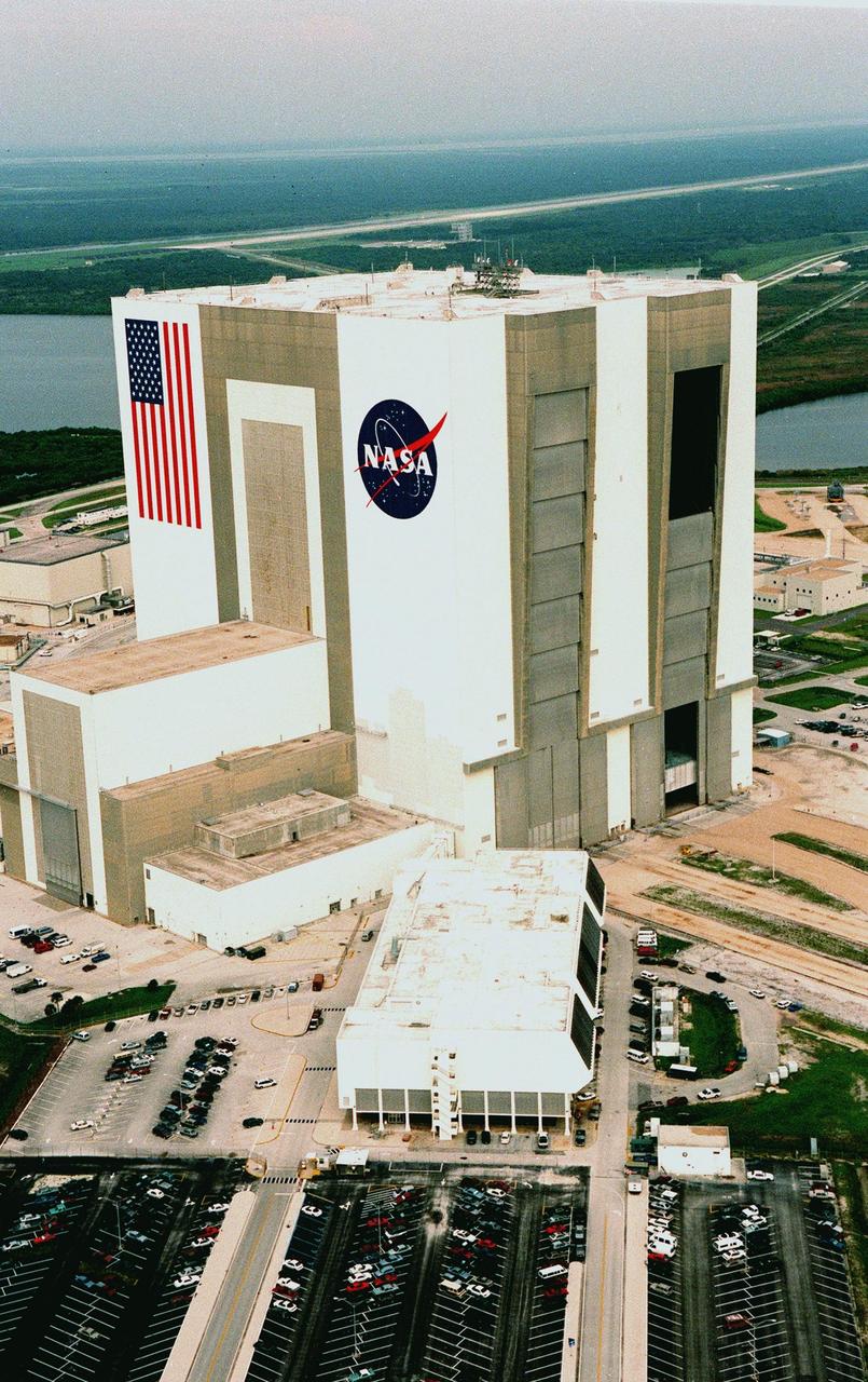
KENNEDY SPACE CENTER, FLA. -- Looking northwest, the Vehicle Assembly Building (VAB) in the Launch Complex 39 area of KSC can be seen with its new coat of paint, along with newly painted American flag and NASA logo. The improved look was finished in time to honor NASA's 40th anniversary on Oct. 1. In order to do the job, workers were suspended on platforms from the top of the 525-foot-high VAB. One of the world's largest buildings by volume, the VAB is the last stop for the Shuttle before rollout to the launch pad. Integration and stacking of the complete Space Shuttle vehicle (orbiter, two solid rocket boosters and the external tank) takes place in High Bays 1 or 3. The High Bay doors (shown partially open), four in all, are 456 feet high. The low-door section, 114 feet high, has four panels that move horizontally. The upper section, 342 feet high, has seven panels that move vertically. It takes about 45 minutes to open all panels. Beyond the VAB is the Shuttle Landing Facility (SLF) and Merritt Island National Wildlife Refuge. The SLF is used for end-of-mission orbiter landings, and also military and civilian cargo carriers, astronauts' T-38 trainers, Shuttle Training Aircraft, and helicopters
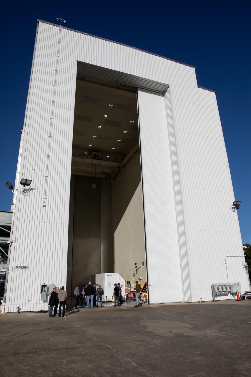
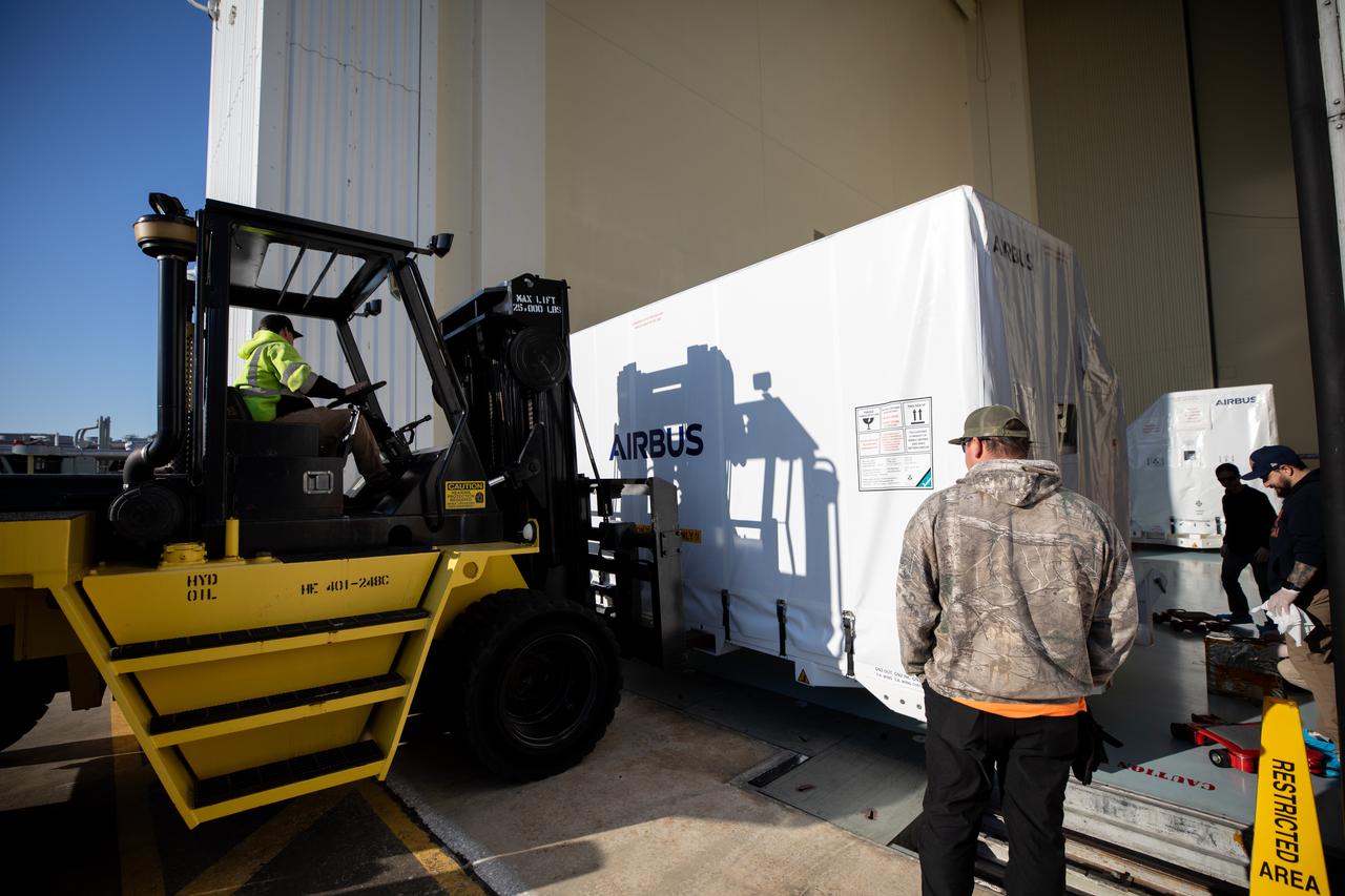
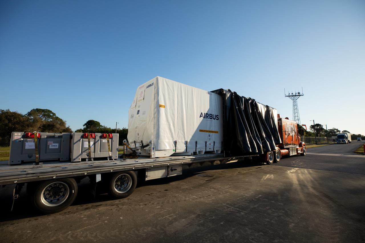
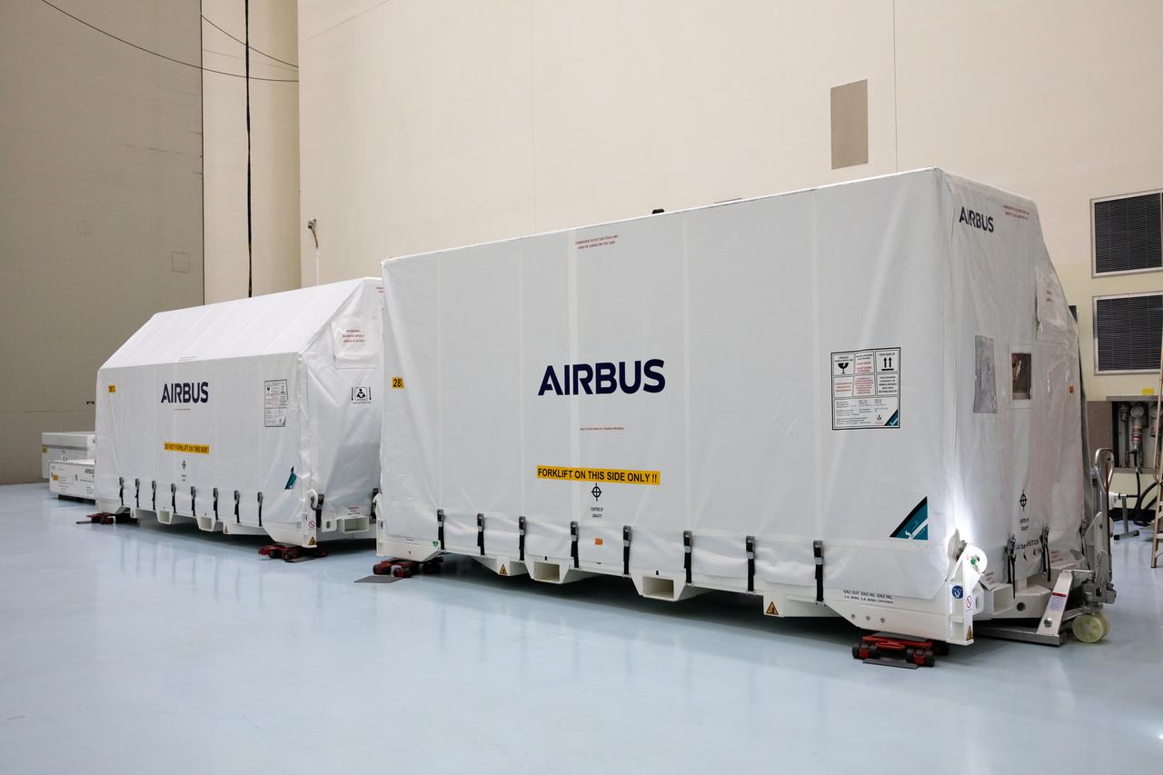
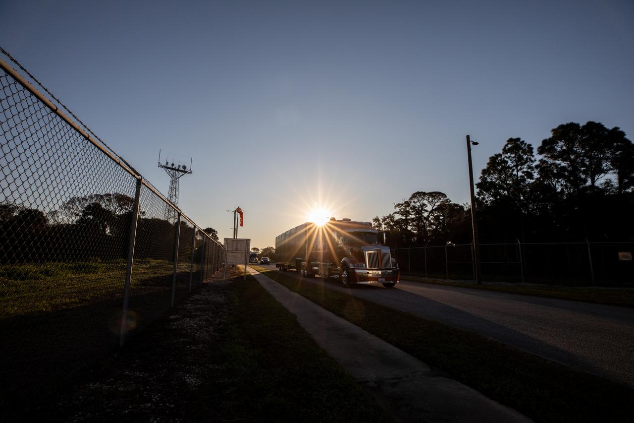
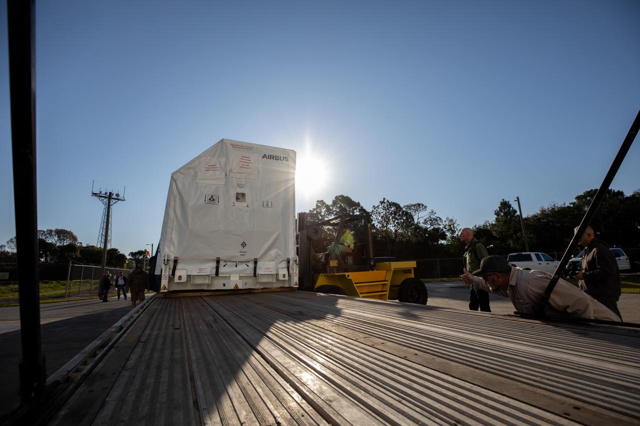
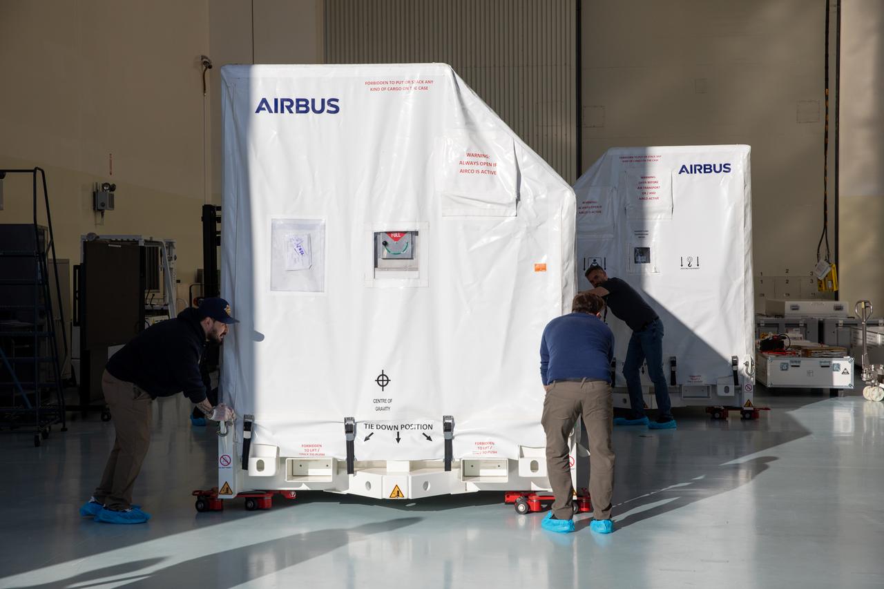
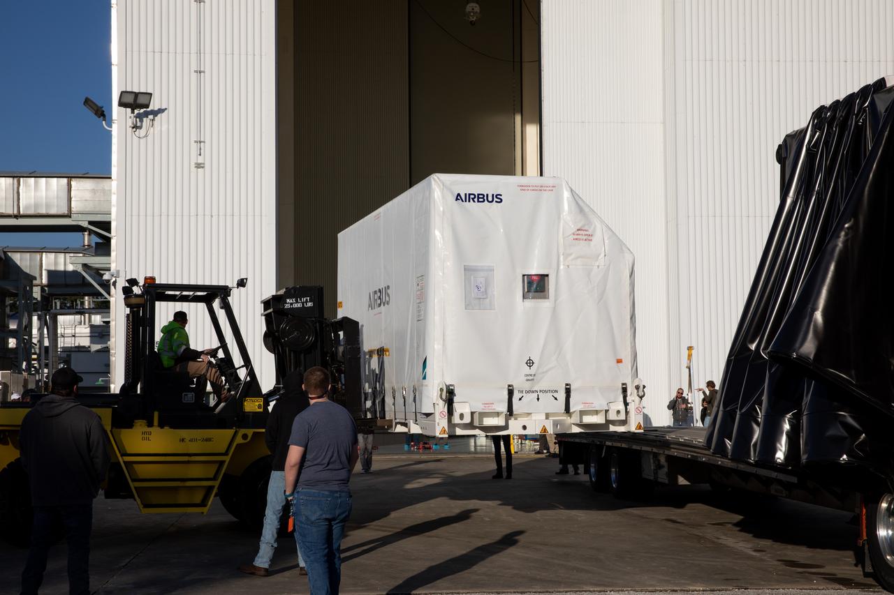
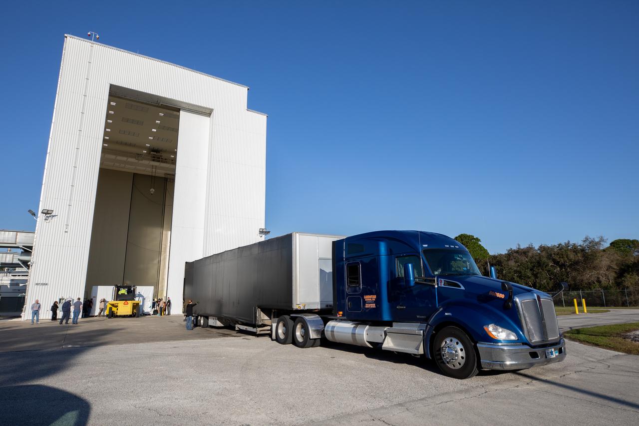
The transport carrier containing the five-panel solar arrays for NASA’s Europa Clipper spacecraft arrives at the Payload Hazardous Servicing Facility at the agency’s Kennedy Space Center in Florida on Wednesday, Feb. 21, 2024. The solar array travelled by air from Leiden, Netherlands, where Airbus workers assembled them over the last year, and then put on a barge to travel to the Port of Miami in Florida and loaded onto a semi-truck to be driven to Kennedy. The solar arrays will attach to the spacecraft to power it for the 1.8-billion-mile journey to study Jupiter’s icy moon, Europa. Launch on a SpaceX Falcon Heavy rocket is no earlier than October 2024.
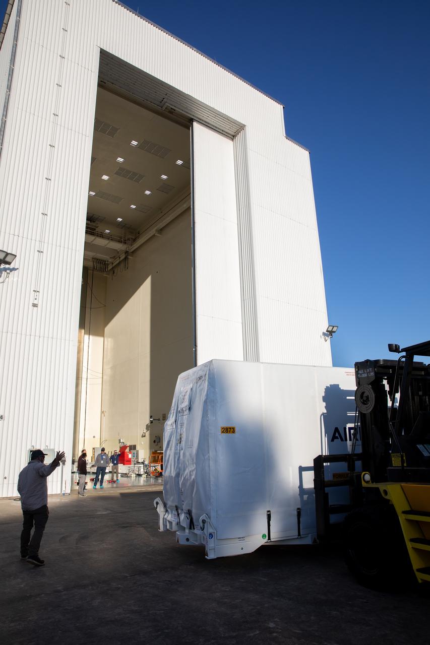
The transport carrier containing the five-panel solar arrays for NASA’s Europa Clipper spacecraft arrives at the Payload Hazardous Servicing Facility at the agency’s Kennedy Space Center in Florida on Wednesday, Feb. 21, 2024. The arrival completes the solar array journey which began in Leiden, Netherlands, where Airbus workers assembled them before shipping them by barge to Port of Miami in Florida and transporting them by truck to Kennedy. The solar arrays will attach to the spacecraft to power it on the 1.8-billion-mile journey to study Jupiter’s icy moon, Europa. Launch on a SpaceX Falcon Heavy rocket is no earlier than October 2024.
The transport carrier containing the five-panel solar arrays for NASA’s Europa Clipper spacecraft arrives at the Payload Hazardous Servicing Facility at the agency’s Kennedy Space Center in Florida on Wednesday, Feb. 21, 2024. The solar array travelled by air from Leiden, Netherlands, where Airbus workers assembled them over the last year, and then put on a barge to travel to the Port of Miami in Florida and loaded onto a semi-truck to be driven to Kennedy. The solar arrays will attach to the spacecraft to power it for the 1.8-billion-mile journey to study Jupiter’s icy moon, Europa. Launch on a SpaceX Falcon Heavy rocket is no earlier than October 2024.
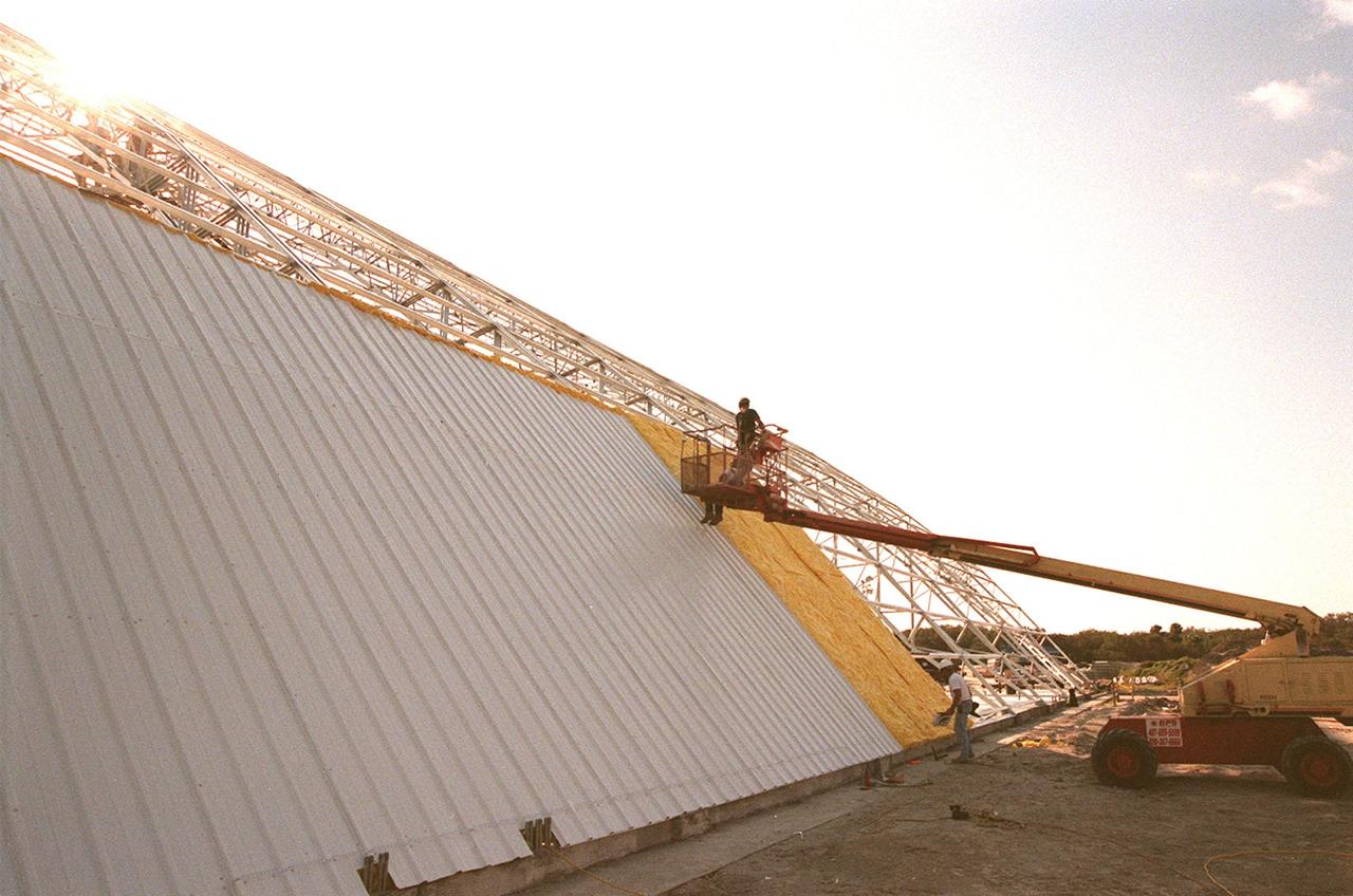
Workers place the first roof panels on the multi-purpose hangar at the site of the $8 million Reusable Launch Vehicle (RLV) Support Complex at Kennedy Space Center. The RLV complex, which includes the hangar and a building for related ground support equipment and administrative/technical support, will be available to accommodate the Space Shuttle; the X-34 RLV technology demonstrator; the L-1011 carrier aircraft for Pegasus and X-34; and other RLV and X-vehicle programs. The complex is jointly funded by the Spaceport Florida Authority, NASA's Space Shuttle Program and KSC. The facility will be operational in early 2000
The transport carrier containing the five-panel solar arrays for NASA’s Europa Clipper spacecraft arrives at the Payload Hazardous Servicing Facility at the agency’s Kennedy Space Center in Florida on Wednesday, Feb. 21, 2024. The arrival completes the solar array journey which began in Leiden, Netherlands, where Airbus workers assembled them before shipping them by barge to Port of Miami in Florida and transporting them by truck to Kennedy. The solar arrays will attach to the spacecraft to power it on the 1.8-billion-mile journey to study Jupiter’s icy moon, Europa. Launch on a SpaceX Falcon Heavy rocket is no earlier than October 2024.
The transport carrier containing the five-panel solar arrays for NASA’s Europa Clipper spacecraft arrives at the Payload Hazardous Servicing Facility at the agency’s Kennedy Space Center in Florida on Wednesday, Feb. 21, 2024. The arrival completes the solar array journey which began in Leiden, Netherlands, where Airbus workers assembled them before shipping them by barge to Port of Miami in Florida and transporting them by truck to Kennedy. The solar arrays will attach to the spacecraft to power it on the 1.8-billion-mile journey to study Jupiter’s icy moon, Europa. Launch on a SpaceX Falcon Heavy rocket is no earlier than October 2024.
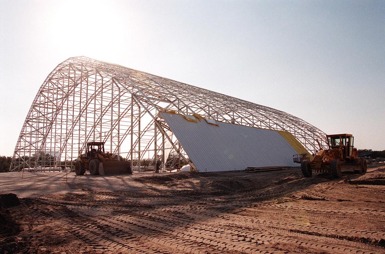
The first roof panels are placed on the multi-purpose hangar at the site of the $8 million Reusable Launch Vehicle (RLV) Support Complex at Kennedy Space Center. The RLV complex, which includes the hangar and a building for related ground support equipment and administrative/technical support, will be available to accommodate the Space Shuttle; the X-34 RLV technology demonstrator; the L-1011 carrier aircraft for Pegasus and X-34; and other RLV and X-vehicle programs. The complex is jointly funded by the Spaceport Florida Authority, NASA's Space Shuttle Program and KSC. The facility will be operational in early 2000
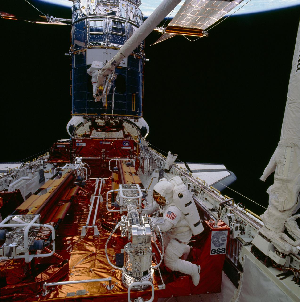
STS061-86-048 (5 Dec 1993) --- Astronauts F. Story Musgrave (foreground) and Jeffrey A. Hoffman are pictured near the end of the first of five extravehicular activity?s (EVA). Musgrave works at the Solar Array Carrier (SAC) in the Space Shuttle Endeavour's cargo bay. Hoffman, anchored to a foot restraint mounted on the end of the Space Shuttle Endeavour's Remote Manipulator System (RMS) arm, waits to be maneuvered to the forward payload bay. The original solar array panels are partially visible at top, while their replacements remain stowed in foreground. The crew's second pair of space walkers -- astronauts Kathryn C. Thornton and Thomas D. Akers -- later changed the solar arrays on the mission's second EVA.
The transport carrier containing the five-panel solar arrays for NASA’s Europa Clipper spacecraft arrives at the Payload Hazardous Servicing Facility at the agency’s Kennedy Space Center in Florida on Wednesday, Feb. 21, 2024. The solar array travelled by air from Leiden, Netherlands, where Airbus workers assembled them over the last year, and then put on a barge to travel to the Port of Miami in Florida and loaded onto a semi-truck to be driven to Kennedy. The solar arrays will attach to the spacecraft to power it for the 1.8-billion-mile journey to study Jupiter’s icy moon, Europa. Launch on a SpaceX Falcon Heavy rocket is no earlier than October 2024.
The transport carrier containing the five-panel solar arrays for NASA’s Europa Clipper spacecraft arrives at the Payload Hazardous Servicing Facility at the agency’s Kennedy Space Center in Florida on Wednesday, Feb. 21, 2024. The arrival completes the solar array journey which began in Leiden, Netherlands, where Airbus workers assembled them before shipping them by barge to Port of Miami in Florida and transporting them by truck to Kennedy. The solar arrays will attach to the spacecraft to power it on the 1.8-billion-mile journey to study Jupiter’s icy moon, Europa. Launch on a SpaceX Falcon Heavy rocket is no earlier than October 2024.
The transport carrier containing the five-panel solar arrays for NASA’s Europa Clipper spacecraft arrives at the Payload Hazardous Servicing Facility at the agency’s Kennedy Space Center in Florida on Wednesday, Feb. 21, 2024. The arrival completes the solar array journey which began in Leiden, Netherlands, where Airbus workers assembled them before shipping them by barge to Port of Miami in Florida and transporting them by truck to Kennedy. The solar arrays will attach to the spacecraft to power it on the 1.8-billion-mile journey to study Jupiter’s icy moon, Europa. Launch on a SpaceX Falcon Heavy rocket is no earlier than October 2024.
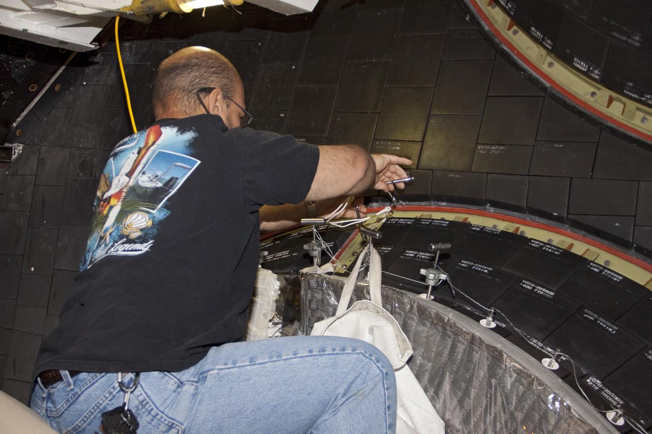
CAPE CANAVERAL, Fla. – At NASA's Kennedy Space Center in Florida, a United Space Alliance technician installs a main engine carrier panel on the space shuttle Atlantis in Bay 2 of the Orbiter Processing Facility. Atlantis is undergoing final preparations for its transfer to the Kennedy Space Center Visitor Complex targeted for November. The work is part of Transition and Retirement of the remaining space shuttles, Atlantis and Endeavour. Atlantis is being prepared for public display at Kennedy's Visitor Complex. Over the course of its 26-year career, Atlantis spent 293 days in space during 33 missions. For more information, visit http://www.nasa.gov/transition Photo credit: NASA/Jim Grossmann
CAPE CANAVERAL, Fla. – At NASA's Kennedy Space Center in Florida, a United Space Alliance technician installs a thermal protection system carrier panel on the space shuttle Atlantis in Bay 2 of the Orbiter Processing Facility. Atlantis is undergoing final preparations for its transfer to the Kennedy Space Center Visitor Complex targeted for November. The work is part of Transition and Retirement of the remaining space shuttles, Atlantis and Endeavour. Atlantis is being prepared for public display at Kennedy's Visitor Complex. Over the course of its 26-year career, Atlantis spent 293 days in space during 33 missions. For more information, visit http://www.nasa.gov/transition Photo credit: NASA/Jim Grossmann
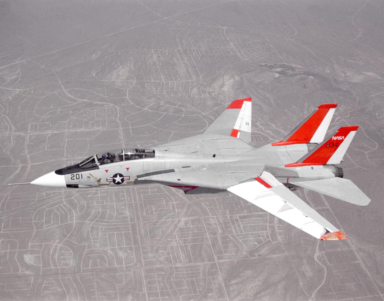
NASA 834, an F-14 Navy Tomcat, seen here in flight, was used at Dryden in 1986 and 1987 in a program known as the Variable-Sweep Transition Flight Experiment (VSTFE). This program explored laminar flow on variable sweep aircraft at high subsonic speeds. An F-14 aircraft was chosen as the carrier vehicle for the VSTFE program primarily because of its variable-sweep capability, Mach and Reynolds number capability, availability, and favorable wing pressure distribution. The variable sweep outer-panels of the F-14 aircraft were modified with natural laminar flow gloves to provide not only smooth surfaces but also airfoils that can produce a wide range of pressure distributions for which transition location can be determined at various flight conditions and sweep angles. Glove I, seen here installed on the upper surface of the left wing, was a "cleanup" or smoothing of the basic F-14 wing, while Glove II was designed to provide specific pressure distributions at Mach 0.7. Laminar flow research continued at Dryden with a research program on the NASA 848 F-16XL, a laminar flow experiment involving a wing-mounted panel with millions of tiny laser cut holes drawing off turbulent boundary layer air with a suction pump.

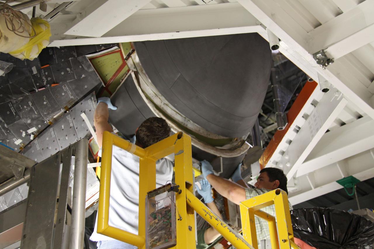
CAPE CANAVERAL, Fla. - In Orbiter Processing Facility 1 at NASA's Kennedy Space Center in Florida, preparations are under way to install the chin panel on space shuttle Atlantis. The chin panel is a semicircular-shaped section of reinforced carbon-carbon that fits under the shuttle's nose cap and is part of its thermal protection system. Atlantis is next slated to deliver an Integrated Cargo Carrier and Russian-built Mini Research Module to the International Space Station on the STS-132 mission. The second in a series of new pressurized components for Russia, the module will be permanently attached to the Zarya module. Three spacewalks are planned to store spare components outside the station, including six spare batteries, a boom assembly for the Ku-band antenna and spares for the Canadian Dextre robotic arm extension. A radiator, airlock and European robotic arm for the Russian Multi-purpose Laboratory Module also are payloads on the flight. Launch is targeted for May 14, 2010. Photo credit: NASA/Troy Cryder
CAPE CANAVERAL, Fla. - In Orbiter Processing Facility 1 at NASA's Kennedy Space Center in Florida, a team of United Space Alliance technicians lifts the chin panel toward space shuttle Atlantis for installation. The chin panel is a semicircular-shaped section of reinforced carbon-carbon that fits under the shuttle's nose cap and is part of its thermal protection system. Atlantis is next slated to deliver an Integrated Cargo Carrier and Russian-built Mini Research Module to the International Space Station on the STS-132 mission. The second in a series of new pressurized components for Russia, the module will be permanently attached to the Zarya module. Three spacewalks are planned to store spare components outside the station, including six spare batteries, a boom assembly for the Ku-band antenna and spares for the Canadian Dextre robotic arm extension. A radiator, airlock and European robotic arm for the Russian Multi-purpose Laboratory Module also are payloads on the flight. Launch is targeted for May 14, 2010. Photo credit: NASA/Ben Smegelsky
CAPE CANAVERAL, Fla. - In Orbiter Processing Facility 1 at NASA's Kennedy Space Center in Florida, United Space Alliance technicians determine the proper placement for the chin panel being installed on space shuttle Atlantis. The chin panel is a semicircular-shaped section of reinforced carbon-carbon that fits under the shuttle's nose cap and is part of its thermal protection system. Atlantis is next slated to deliver an Integrated Cargo Carrier and Russian-built Mini Research Module to the International Space Station on the STS-132 mission. The second in a series of new pressurized components for Russia, the module will be permanently attached to the Zarya module. Three spacewalks are planned to store spare components outside the station, including six spare batteries, a boom assembly for the Ku-band antenna and spares for the Canadian Dextre robotic arm extension. A radiator, airlock and European robotic arm for the Russian Multi-purpose Laboratory Module also are payloads on the flight. Launch is targeted for May 14, 2010. Photo credit: NASA/Ben Smegelsky
CAPE CANAVERAL, Fla. - In Orbiter Processing Facility 1 at NASA's Kennedy Space Center in Florida, United Space Alliance technicians complete the installation of the chin panel on space shuttle Atlantis. The chin panel is a semicircular-shaped section of reinforced carbon-carbon that fits under the shuttle's nose cap and is part of its thermal protection system. Atlantis is next slated to deliver an Integrated Cargo Carrier and Russian-built Mini Research Module to the International Space Station on the STS-132 mission. The second in a series of new pressurized components for Russia, the module will be permanently attached to the Zarya module. Three spacewalks are planned to store spare components outside the station, including six spare batteries, a boom assembly for the Ku-band antenna and spares for the Canadian Dextre robotic arm extension. A radiator, airlock and European robotic arm for the Russian Multi-purpose Laboratory Module also are payloads on the flight. Launch is targeted for May 14, 2010. Photo credit: NASA/Ben Smegelsky
CAPE CANAVERAL, Fla. - In Orbiter Processing Facility 1 at NASA's Kennedy Space Center in Florida, United Space Alliance technicians prepare to install the chin panel on space shuttle Atlantis. The chin panel is a semicircular-shaped section of reinforced carbon-carbon that fits under the shuttle's nose cap and is part of its thermal protection system. Atlantis is next slated to deliver an Integrated Cargo Carrier and Russian-built Mini Research Module to the International Space Station on the STS-132 mission. The second in a series of new pressurized components for Russia, the module will be permanently attached to the Zarya module. Three spacewalks are planned to store spare components outside the station, including six spare batteries, a boom assembly for the Ku-band antenna and spares for the Canadian Dextre robotic arm extension. A radiator, airlock and European robotic arm for the Russian Multi-purpose Laboratory Module also are payloads on the flight. Launch is targeted for May 14, 2010. Photo credit: NASA/Ben Smegelsky
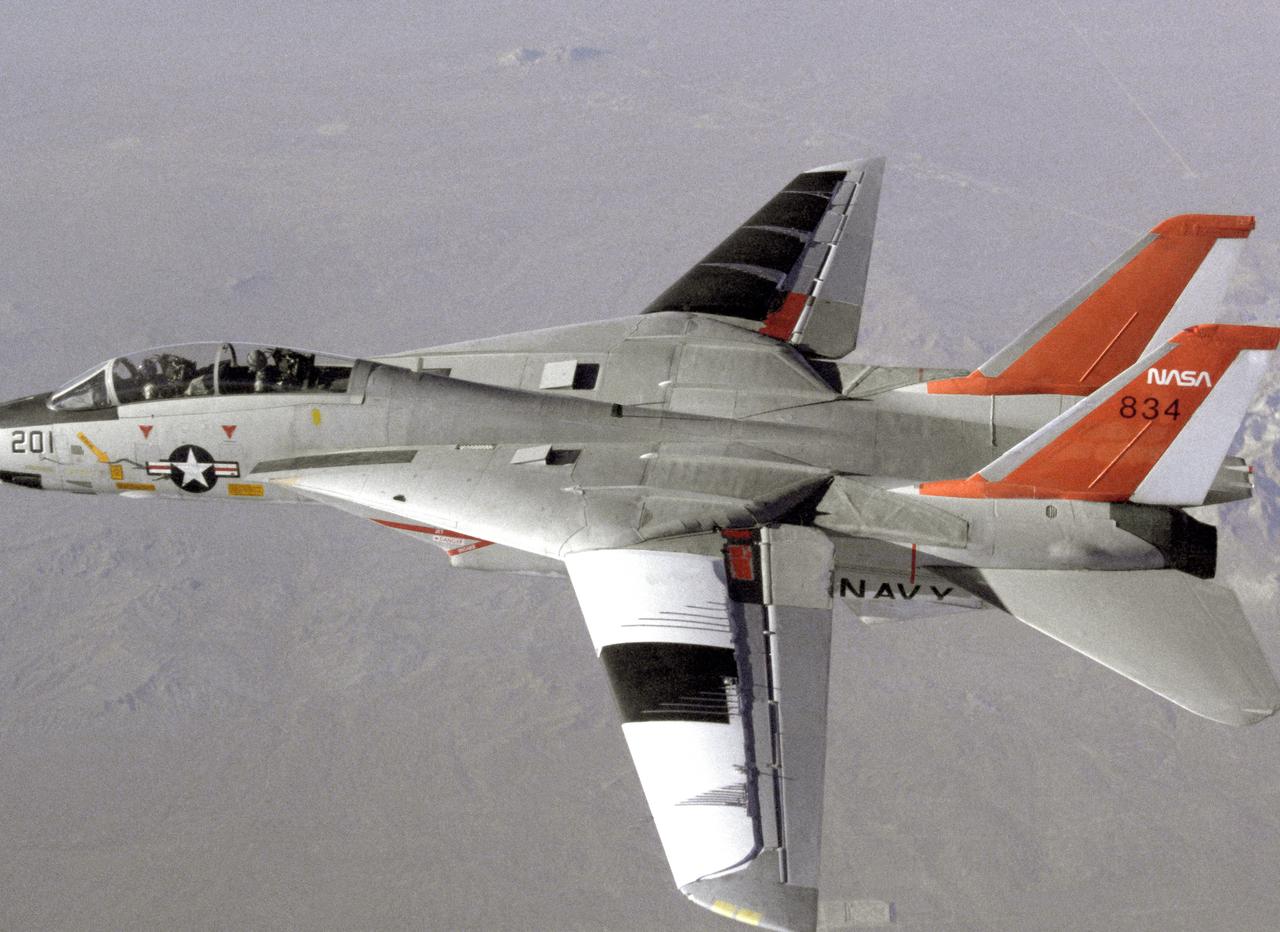
NASA 834, an F-14 Navy Tomcat, seen here in flight, was used at Dryden in 1986 and 1987 in a program known as the Variable-Sweep Transition Flight Experiment (VSTFE). This program explored laminar flow on variable sweep aircraft at high subsonic speeds. An F-14 aircraft was chosen as the carrier vehicle for the VSTFE program primarily because of its variable-sweep capability, Mach and Reynolds number capability, availability, and favorable wing pressure distribution. The variable sweep outer-panels of the F-14 aircraft were modified with natural laminar flow gloves to provide not only smooth surfaces but also airfoils that can produce a wide range of pressure distributions for which transition location can be determined at various flight conditions and sweep angles. Glove I, seen here installed on the upper surface of the left wing, was a "cleanup" or smoothing of the basic F-14 wing, while Glove II was designed to provide specific pressure distributions at Mach 0.7. Laminar flow research continued at Dryden with a research program on the NASA 848 F-16XL, a laminar flow experiment involving a wing-mounted panel with millions of tiny laser cut holes drawing off turbulent boundary layer air with a suction pump.
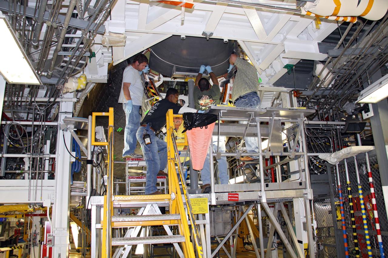
CAPE CANAVERAL, Fla. - In Orbiter Processing Facility 1 at NASA's Kennedy Space Center in Florida, a team of United Space Alliance technicians installs the chin panel on space shuttle Atlantis. The chin panel is a semicircular-shaped section of reinforced carbon-carbon that fits under the shuttle's nose cap and is part of its thermal protection system. Atlantis is next slated to deliver an Integrated Cargo Carrier and Russian-built Mini Research Module to the International Space Station on the STS-132 mission. The second in a series of new pressurized components for Russia, the module will be permanently attached to the Zarya module. Three spacewalks are planned to store spare components outside the station, including six spare batteries, a boom assembly for the Ku-band antenna and spares for the Canadian Dextre robotic arm extension. A radiator, airlock and European robotic arm for the Russian Multi-purpose Laboratory Module also are payloads on the flight. Launch is targeted for May 14, 2010. Photo credit: NASA/Ben Smegelsky
CAPE CANAVERAL, Fla. - In Orbiter Processing Facility 1 at NASA's Kennedy Space Center in Florida, United Space Alliance technicians position the chin panel on space shuttle Atlantis for installation. The chin panel is a semicircular-shaped section of reinforced carbon-carbon that fits under the shuttle's nose cap and is part of its thermal protection system. Atlantis is next slated to deliver an Integrated Cargo Carrier and Russian-built Mini Research Module to the International Space Station on the STS-132 mission. The second in a series of new pressurized components for Russia, the module will be permanently attached to the Zarya module. Three spacewalks are planned to store spare components outside the station, including six spare batteries, a boom assembly for the Ku-band antenna and spares for the Canadian Dextre robotic arm extension. A radiator, airlock and European robotic arm for the Russian Multi-purpose Laboratory Module also are payloads on the flight. Launch is targeted for May 14, 2010. Photo credit: NASA/Ben Smegelsky
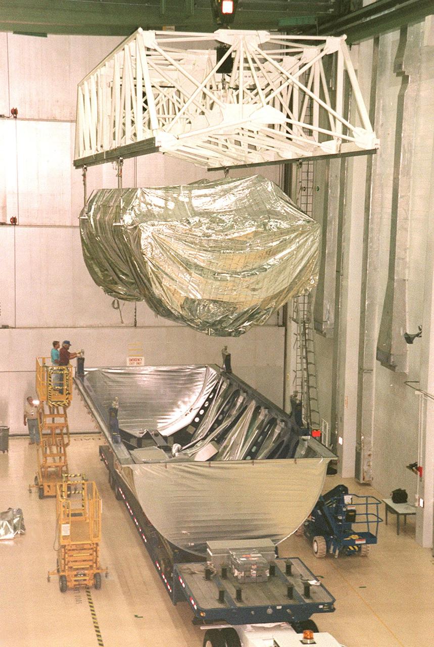
KENNEDY SPACE CENTER, FLA. -- Inside the Operations and Checkout Building, a strongback lifts the S1 truss from the Guppy cargo carrier that protected it during flight and transfer. Manufactured by the Boeing Co. in Huntington Beach, Calif., this component of the International Space Station is the first starboard (right-side) truss segment, whose main job is providing structural support for the orbiting research facility's radiator panels that cool the Space Station's complex power system. The S1 truss segment also will house communications systems, external experiment positions and other subsystems. Primarily constructed of aluminum, the truss segment is 45 feet long, 15 feet wide and 6 feet tall. When fully outfitted, it will weigh 31,137 pounds. The truss is slated for flight in 2001
CAPE CANAVERAL, Fla. – In Orbiter Processing Facility Bay 2 at NASA’s Kennedy Space Center in Florida, the final heat shield carrier panel has been installed on the space shuttle Endeavour. The orbiter is now ready for its tail cone to be installed for the cross-country ferry flight. The work is part of Transition and Retirement of the remaining space shuttles, Endeavour and Atlantis. Endeavour is being prepared for public display at the California Science Center in Los Angeles. Its ferry flight to California is targeted for mid-September. Endeavour was the last space shuttle added to NASA’s orbiter fleet. Over the course of its 19-year career, Endeavour spent 299 days in space during 25 missions. For more information, visit http://www.nasa.gov/transition Photo credit: NASA/ Frankie Martin
CAPE CANAVERAL, Fla. – In Orbiter Processing Facility Bay 2 at NASA’s Kennedy Space Center in Florida, United Space Alliance aerospace technician Chris Peluso installs a heat shield carrier panel on the space shuttle Endeavour. The work is part of Transition and Retirement of the remaining space shuttles, Endeavour and Atlantis. Endeavour is being prepared for public display at the California Science Center in Los Angeles. Its ferry flight to California is targeted for mid-September. Endeavour was the last space shuttle added to NASA’s orbiter fleet. Over the course of its 19-year career, Endeavour spent 299 days in space during 25 missions. For more information, visit http://www.nasa.gov/transition Photo credit: NASA/ Jim Grossmann
CAPE CANAVERAL, Fla. – In Orbiter Processing Facility Bay 2 at NASA’s Kennedy Space Center in Florida, United Space Alliance aerospace technician Tom Goldean installs a heat shield carrier panel on the space shuttle Endeavour. The work is part of Transition and Retirement of the remaining space shuttles, Endeavour and Atlantis. Endeavour is being prepared for public display at the California Science Center in Los Angeles. Its ferry flight to California is targeted for mid-September. Endeavour was the last space shuttle added to NASA’s orbiter fleet. Over the course of its 19-year career, Endeavour spent 299 days in space during 25 missions. For more information, visit http://www.nasa.gov/transition Photo credit: NASA/ Jim Grossmann
CAPE CANAVERAL, Fla. – In Orbiter Processing Facility Bay 2 at NASA’s Kennedy Space Center in Florida, United Space Alliance technicians install an outer heat shield carrier panel on the space shuttle Endeavour. The work is part of Transition and Retirement of the remaining space shuttles, Endeavour and Atlantis. Endeavour is being prepared for public display at the California Science Center in Los Angeles. Its ferry flight to California is targeted for mid-September. Endeavour was the last space shuttle added to NASA’s orbiter fleet. Over the course of its 19-year career, Endeavour spent 299 days in space during 25 missions. For more information, visit http://www.nasa.gov/transition Photo credit: NASA/ Frankie Martin
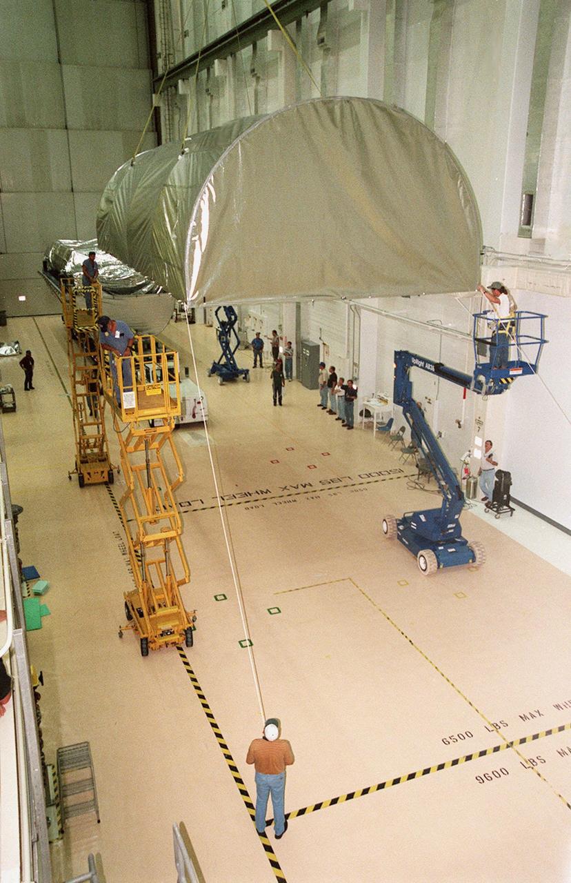
KENNEDY SPACE CENTER, FLA. -- Inside the Operations and Checkout Building, the top of the Guppy cargo carrier is lifted off the S1 truss (background). Manufactured by the Boeing Co. in Huntington Beach, Calif., this component of the International Space Station is the first starboard (right-side) truss segment, whose main job is providing structural support for the orbiting research facility's radiator panels that cool the Space Station's complex power system. The S1 truss segment also will house communications systems, external experiment positions and other subsystems. Primarily constructed of aluminum, the truss segment is 45 feet long, 15 feet wide and 6 feet tall. When fully outfitted, it will weigh 31,137 pounds. The truss is slated for flight in 2001
Inside Building 1555 at Vandenberg Air Force Base in California, solar panels for one of eight NASA's Cyclone Global Navigation Satellite System (CYGNSS) spacecraft has been deployed for illumination testing. Processing activities will prepare the spacecraft for launch aboard an Orbital ATK Pegasus XL rocket. When preparations are completed at Vandenberg, the rocket will be transported to NASA's Kennedy Space Center in Florida attached to the Orbital ATK L-1011 carrier aircraft within its payload fairing. CYGNSS will launch on the Pegasus XL rocket from the Skid Strip at Cape Canaveral Air Force Station. CYGNSS will make frequent and accurate measurements of ocean surface winds throughout the life cycle of tropical storms and hurricanes. The data that CYGNSS provides will enable scientists to probe key air-sea interaction processes that take place near the core of storms, which are rapidly changing and play a critical role in the beginning and intensification of hurricanes.

KENNEDY SPACE CENTER, FLA. -- A KSC transporter moves the Guppy cargo carrier encasing the S1 truss into the Operations and Checkout Building. Manufactured by the Boeing Co. in Huntington Beach, Calif., this component of the International Space Station is the first starboard (right-side) truss segment, whose main job is providing structural support for the orbiting research facility's radiator panels that cool the Space Station's complex power system. The S1 truss segment also will house communications systems, external experiment positions and other subsystems. Primarily constructed of aluminum, the truss segment is 45 feet long, 15 feet wide and 6 feet tall. When fully outfitted, it will weigh 31,137 pounds. The truss is slated for flight in 2001
CAPE CANAVERAL, Fla. – In Orbiter Processing Facility Bay 2 at NASA’s Kennedy Space Center in Florida, a United Space Alliance technician installs a heat shield carrier panel on the space shuttle Endeavour. The work is part of Transition and Retirement of the remaining space shuttles, Endeavour and Atlantis. Endeavour is being prepared for public display at the California Science Center in Los Angeles. Its ferry flight to California is targeted for mid-September. Endeavour was the last space shuttle added to NASA’s orbiter fleet. Over the course of its 19-year career, Endeavour spent 299 days in space during 25 missions. For more information, visit http://www.nasa.gov/transition Photo credit: NASA/ Jim Grossmann
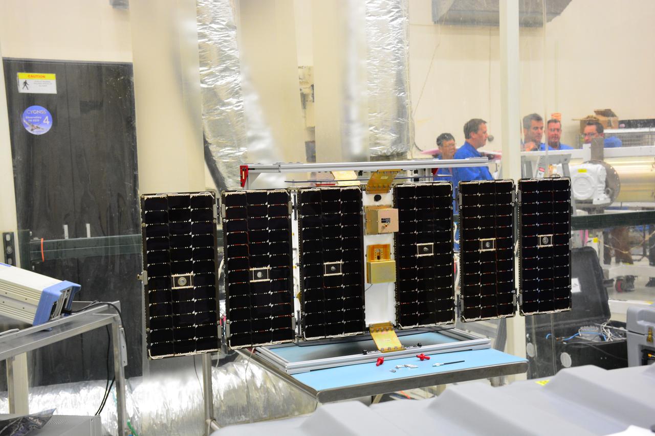
Inside Building 1555 at Vandenberg Air Force Base in California, solar panels for one of eight NASA's Cyclone Global Navigation Satellite System (CYGNSS) spacecraft has been deployed for illumination testing. Processing activities will prepare the spacecraft for launch aboard an Orbital ATK Pegasus XL rocket. When preparations are completed at Vandenberg, the rocket will be transported to NASA's Kennedy Space Center in Florida attached to the Orbital ATK L-1011 carrier aircraft within its payload fairing. CYGNSS will launch on the Pegasus XL rocket from the Skid Strip at Cape Canaveral Air Force Station. CYGNSS will make frequent and accurate measurements of ocean surface winds throughout the life cycle of tropical storms and hurricanes. The data that CYGNSS provides will enable scientists to probe key air-sea interaction processes that take place near the core of storms, which are rapidly changing and play a critical role in the beginning and intensification of hurricanes.
CAPE CANAVERAL, Fla. – In Orbiter Processing Facility Bay 2 at NASA’s Kennedy Space Center in Florida, United Space Alliance aerospace technician Chris Peluso installs a heat shield carrier panel on the space shuttle Endeavour. The work is part of Transition and Retirement of the remaining space shuttles, Endeavour and Atlantis. Endeavour is being prepared for public display at the California Science Center in Los Angeles. Its ferry flight to California is targeted for mid-September. Endeavour was the last space shuttle added to NASA’s orbiter fleet. Over the course of its 19-year career, Endeavour spent 299 days in space during 25 missions. For more information, visit http://www.nasa.gov/transition Photo credit: NASA/ Jim Grossmann
CAPE CANAVERAL, Fla. – In Orbiter Processing Facility Bay 2 at NASA’s Kennedy Space Center in Florida, a United Space Alliance technician installs an outer heat shield carrier panel on the space shuttle Endeavour. The work is part of Transition and Retirement of the remaining space shuttles, Endeavour and Atlantis. Endeavour is being prepared for public display at the California Science Center in Los Angeles. Its ferry flight to California is targeted for mid-September. Endeavour was the last space shuttle added to NASA’s orbiter fleet. Over the course of its 19-year career, Endeavour spent 299 days in space during 25 missions. For more information, visit http://www.nasa.gov/transition Photo credit: NASA/ Frankie Martin
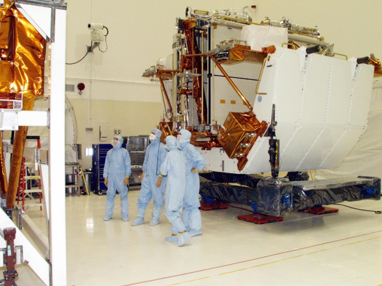
VANDENBERG AIR FORCE BASE, Calif. – Inside an environmental enclosure at Vandenberg Air Force Base's processing facility in California, solar panels line the sides of NASA's Nuclear Spectroscopic Telescope Array, or NuSTAR, spacecraft. NuSTAR is newly mated with its Orbital Sciences Pegasus XL rocket. The uniting of the spacecraft with the rocket is a major milestone in prelaunch preparations. After processing of the rocket and spacecraft are complete, they will be flown on Orbital's L-1011 carrier aircraft from Vandenberg to the Ronald Reagan Ballistic Missile Defense Test Site on the Pacific Ocean’s Kwajalein Atoll for launch. The high-energy x-ray telescope will conduct a census of black holes, map radioactive material in young supernovae remnants, and study the origins of cosmic rays and the extreme physics around collapsed stars. For more information, visit http://www.nasa.gov/nustar. Photo credit: NASA/Randy Beaudoin, VAFB

CAPE CANAVERAL, Fla. – In Orbiter Processing Facility Bay 2 at NASA’s Kennedy Space Center in Florida, United Space Alliance aerospace technicians Hector Castillo, left, and Tom Goldean inspect a heat shield carrier panel to be installed on the space shuttle Endeavour. The work is part of Transition and Retirement of the remaining space shuttles, Endeavour and Atlantis. Endeavour is being prepared for public display at the California Science Center in Los Angeles. Its ferry flight to California is targeted for mid-September. Endeavour was the last space shuttle added to NASA’s orbiter fleet. Over the course of its 19-year career, Endeavour spent 299 days in space during 25 missions. For more information, visit http://www.nasa.gov/transition Photo credit: NASA/ Jim Grossmann
CAPE CANAVERAL, Fla. – In Orbiter Processing Facility Bay 2 at NASA’s Kennedy Space Center in Florida, United Space Alliance aerospace technician Chris Peluso installs a heat shield carrier panel on the space shuttle Endeavour. The work is part of Transition and Retirement of the remaining space shuttles, Endeavour and Atlantis. Endeavour is being prepared for public display at the California Science Center in Los Angeles. Its ferry flight to California is targeted for mid-September. Endeavour was the last space shuttle added to NASA’s orbiter fleet. Over the course of its 19-year career, Endeavour spent 299 days in space during 25 missions. For more information, visit http://www.nasa.gov/transition Photo credit: NASA/ Jim Grossmann
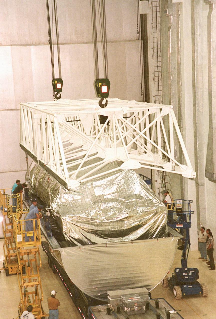
KENNEDY SPACE CENTER, FLA. -- Inside the Operations and Checkout Building, a strongback is lowered toward the S1 truss below it in order to lift the truss from the Guppy cargo carrier that protected it during flight and transfer. Manufactured by the Boeing Co. in Huntington Beach, Calif., this component of the International Space Station is the first starboard (right-side) truss segment, whose main job is providing structural support for the orbiting research facility's radiator panels that cool the Space Station's complex power system. The S1 truss segment also will house communications systems, external experiment positions and other subsystems. Primarily constructed of aluminum, the truss segment is 45 feet long, 15 feet wide and 6 feet tall. When fully outfitted, it will weigh 31,137 pounds. The truss is slated for flight in 2001
VANDENBERG AIR FORCE BASE, Calif. – Inside an environmental enclosure at Vandenberg Air Force Base's processing facility in California, the solar panels on NASA's Nuclear Spectroscopic Telescope Array, or NuSTAR, are in view after the removal of the turnover rotation fixture from around the spacecraft. The fixture was used to rotate the spacecraft into a horizontal position and supported it during its mating to an Orbital Sciences Pegasus XL rocket. The uniting of the spacecraft with the rocket is a major milestone in prelaunch preparations. After processing of the rocket and spacecraft are complete, they will be flown on Orbital's L-1011 carrier aircraft from Vandenberg to the Ronald Reagan Ballistic Missile Defense Test Site on the Pacific Ocean’s Kwajalein Atoll for launch. The high-energy x-ray telescope will conduct a census of black holes, map radioactive material in young supernovae remnants, and study the origins of cosmic rays and the extreme physics around collapsed stars. For more information, visit http://www.nasa.gov/nustar. Photo credit: NASA/Randy Beaudoin, VAFB
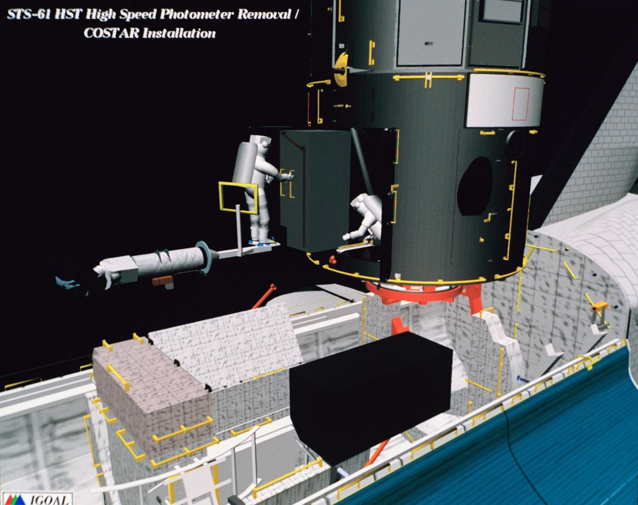
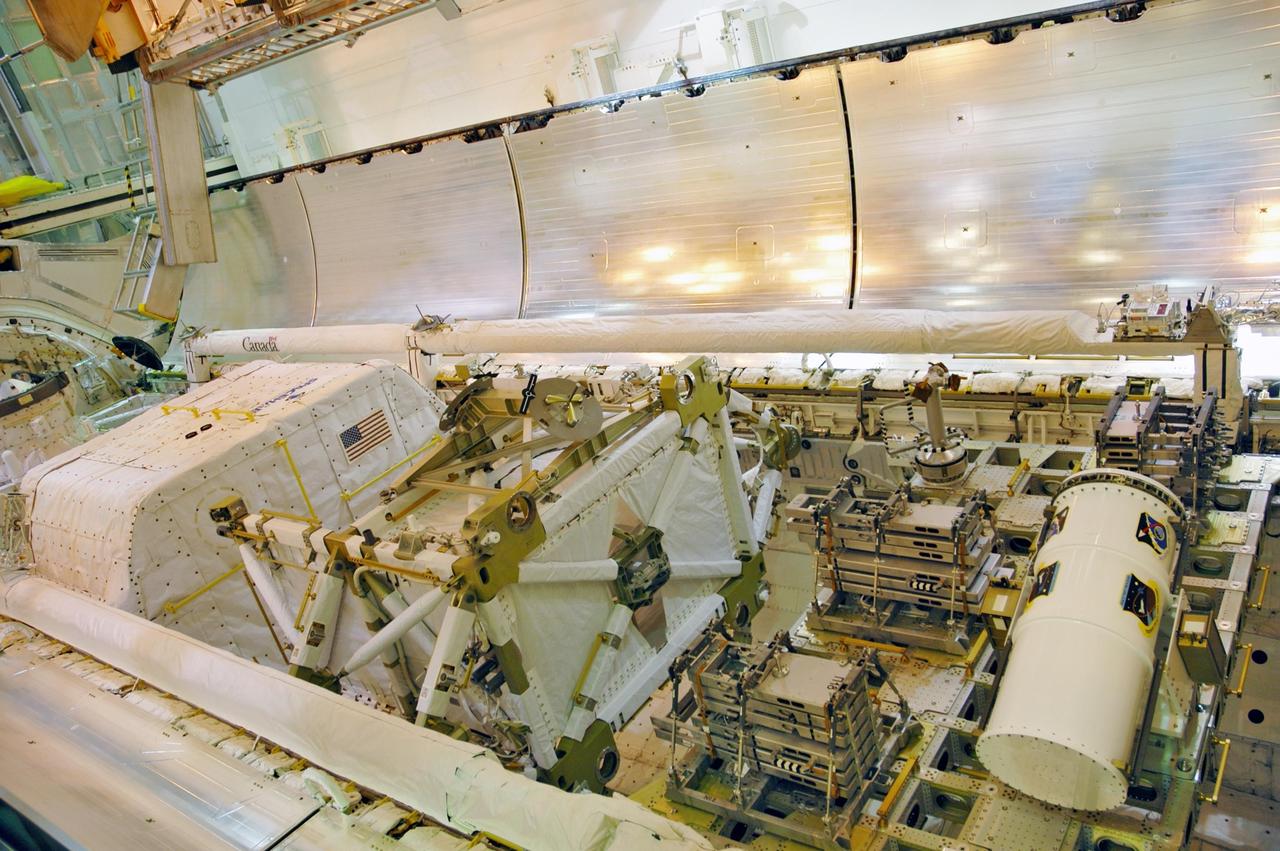
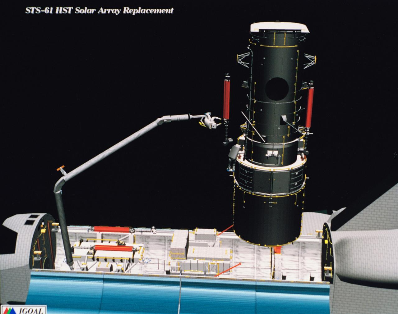
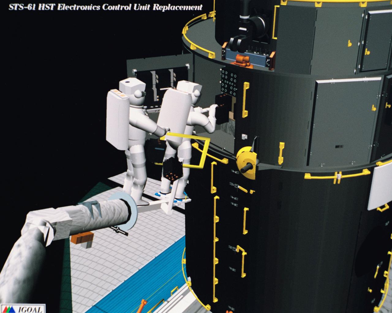
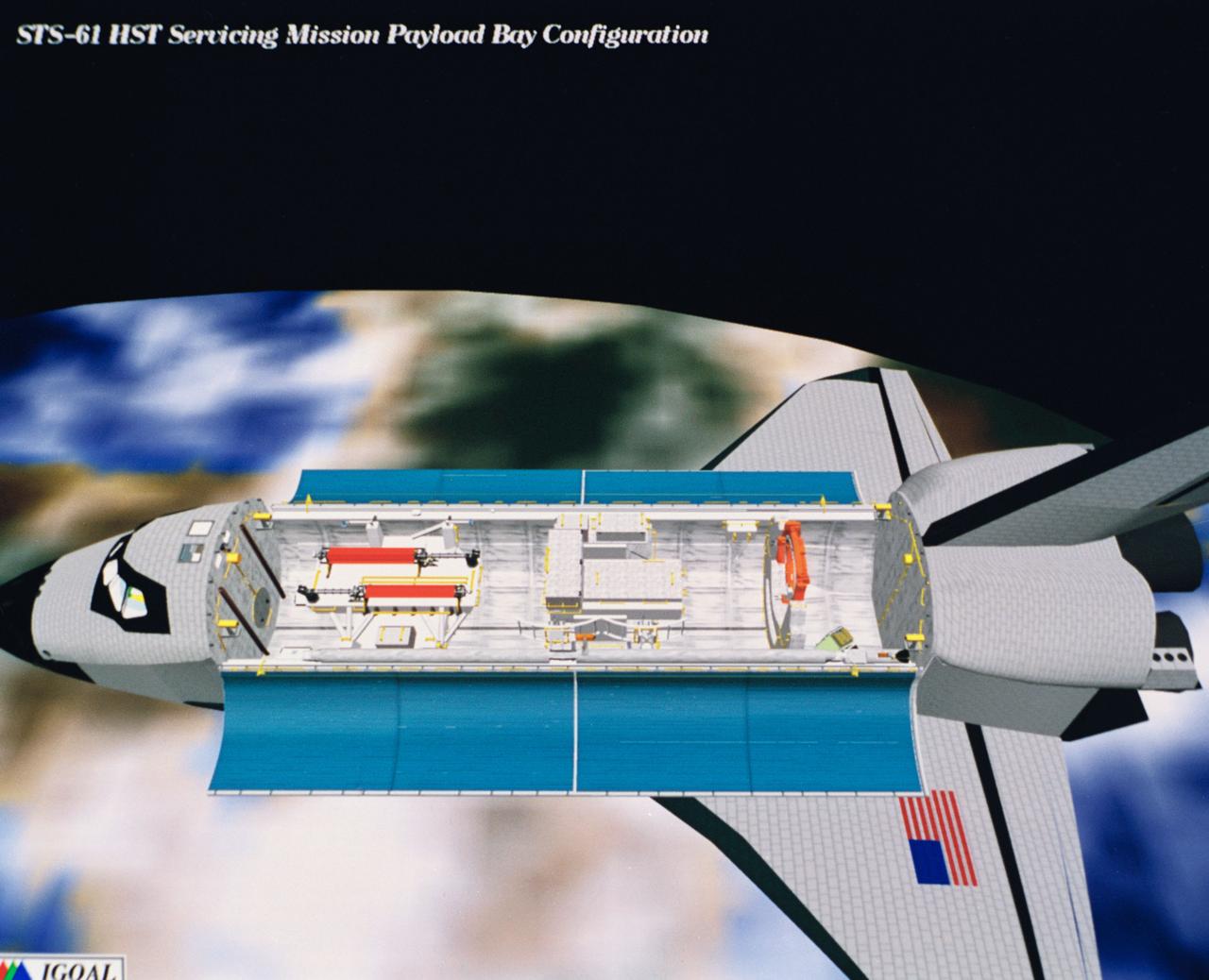
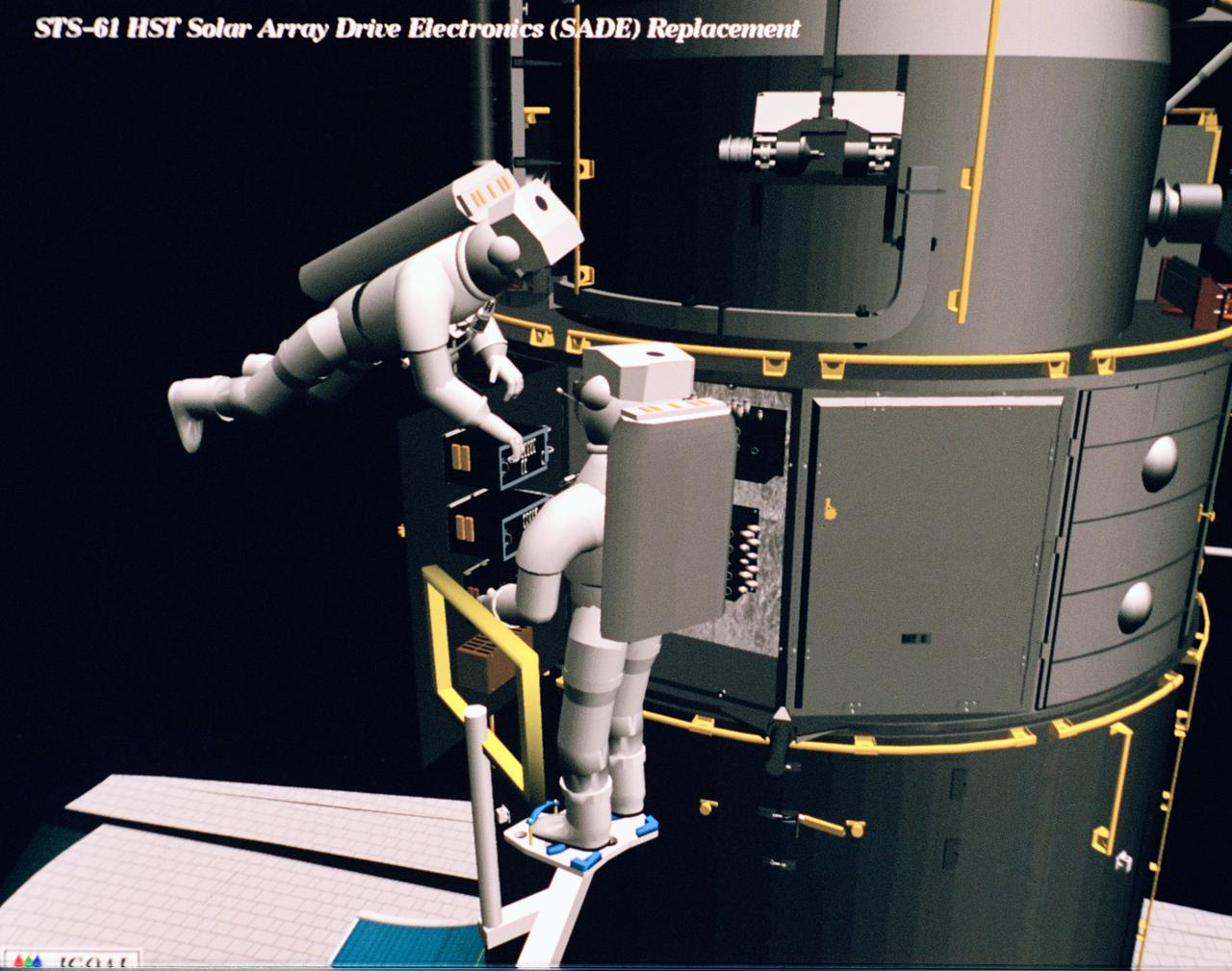
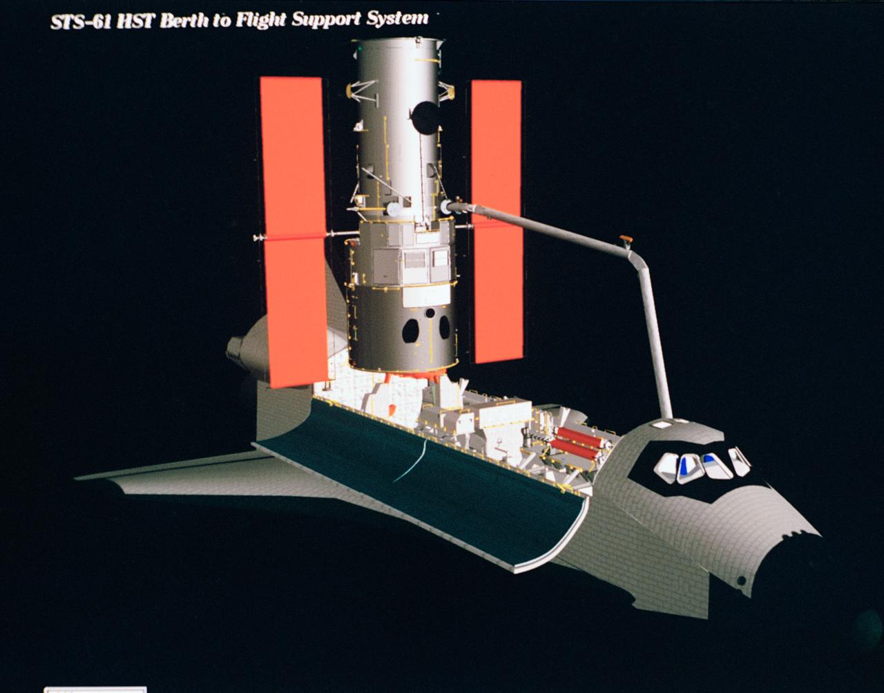
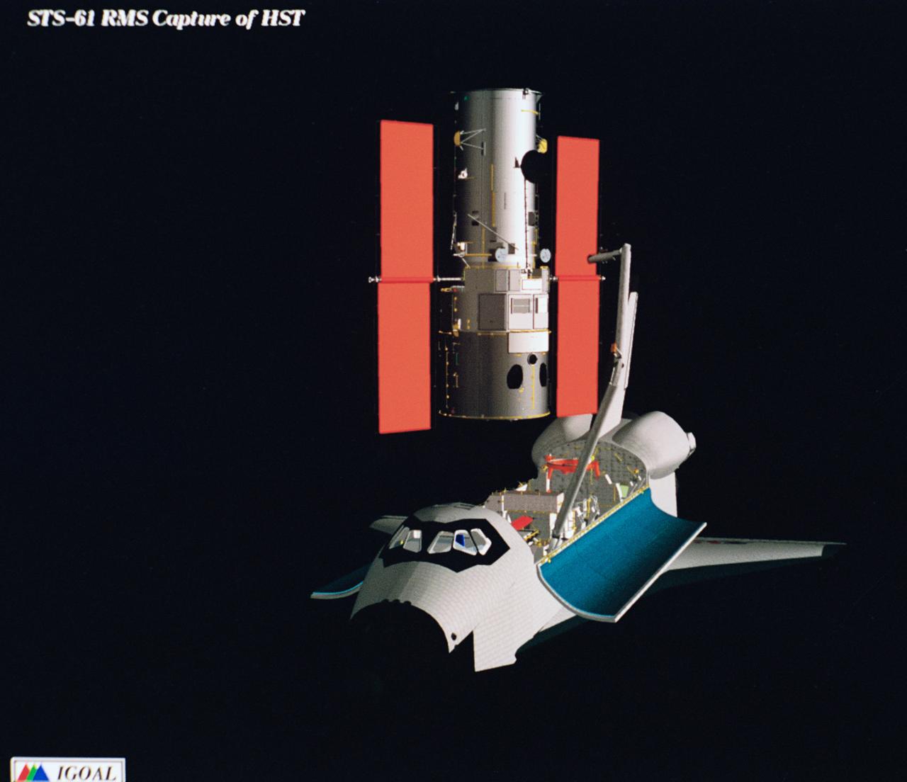
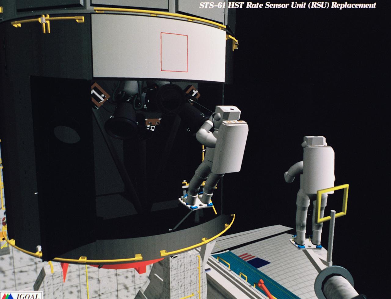
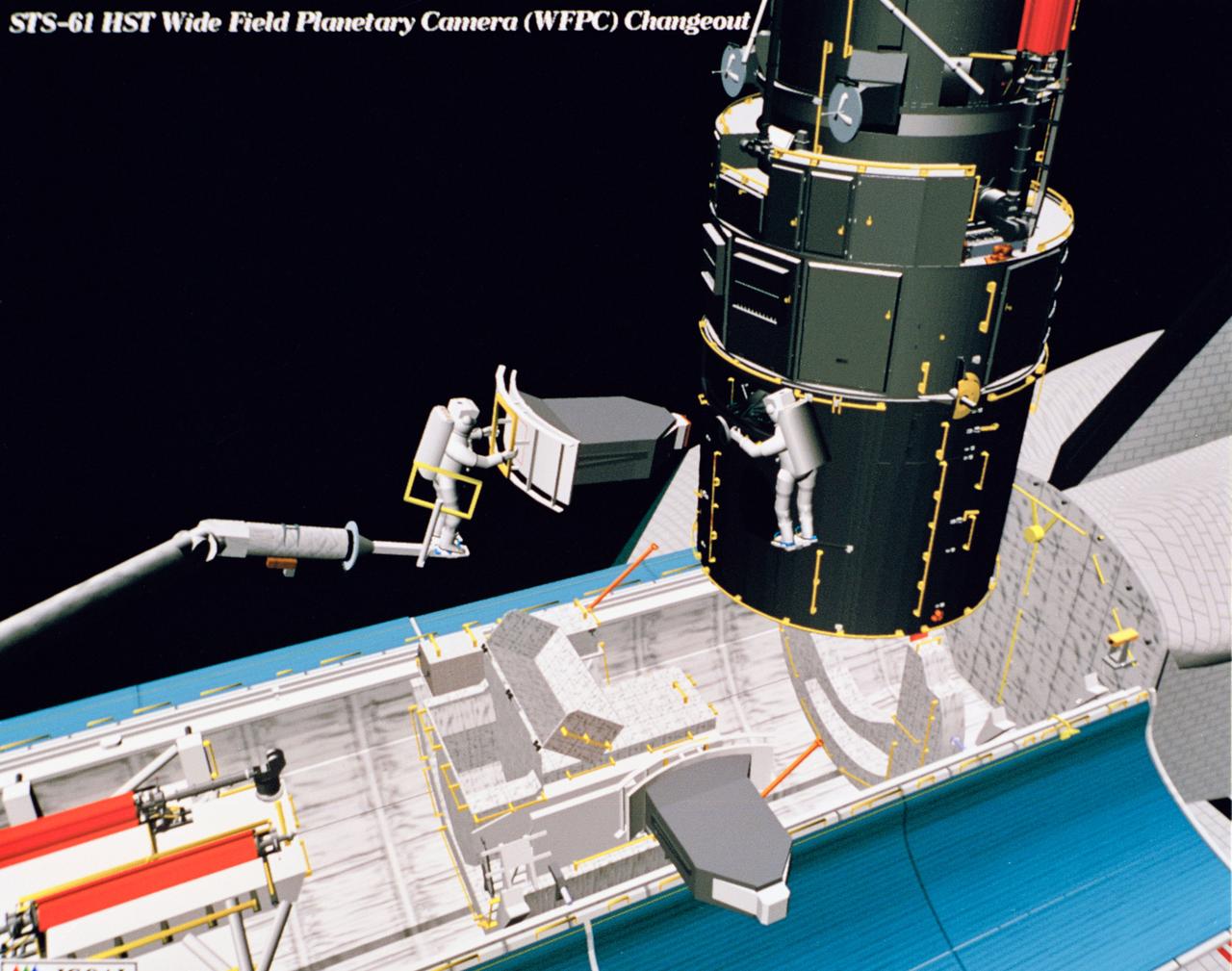
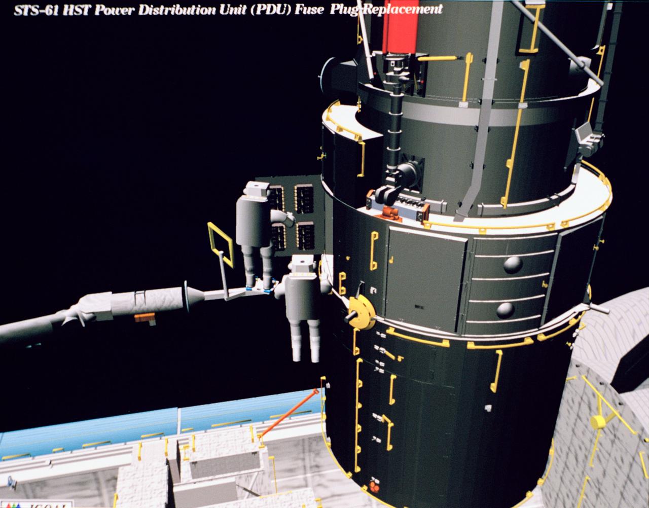
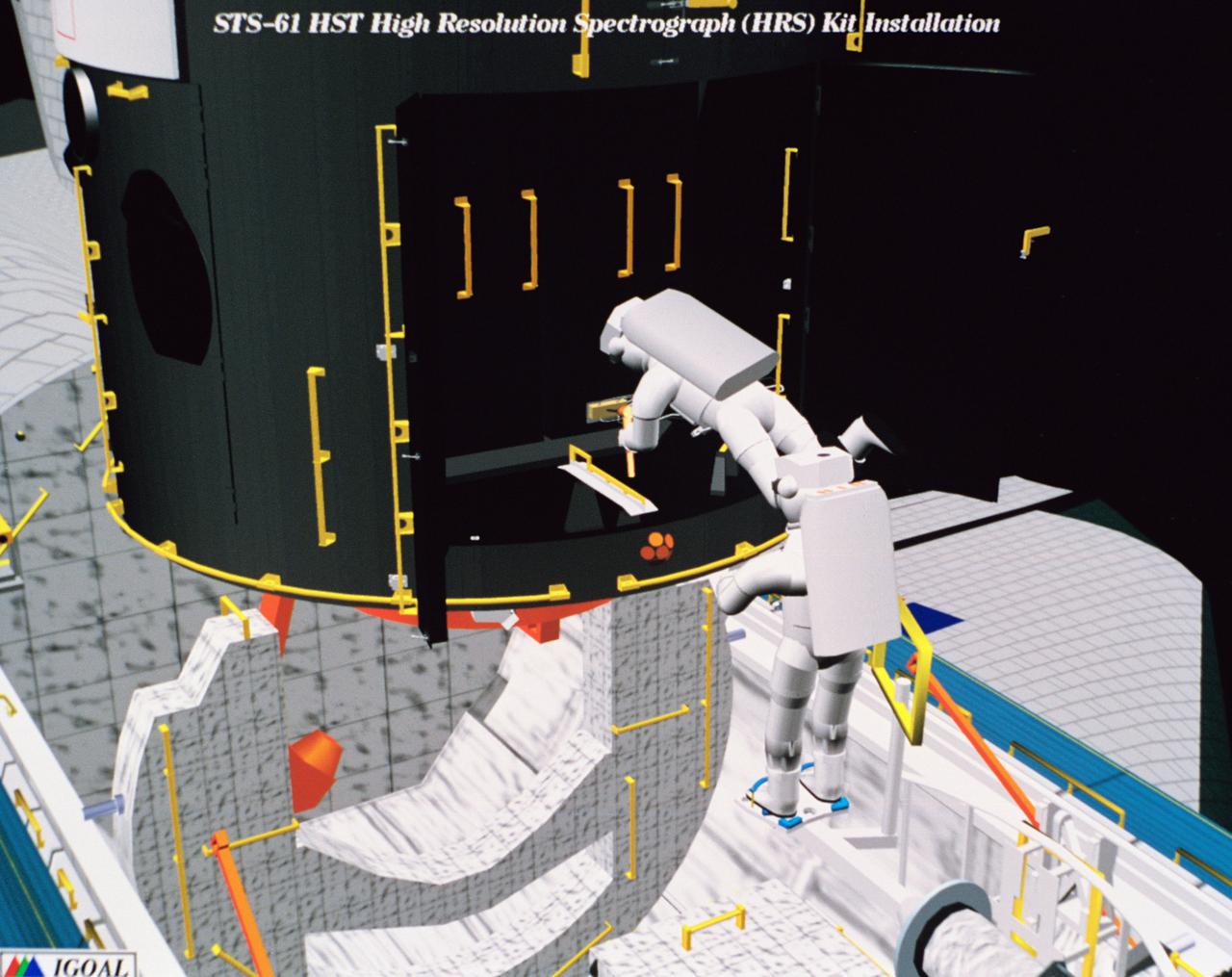
Computer generated scenes depicting the Hubble Space Telescope capture and a sequence of planned events on the planned extravehicular activity (EVA). Scenes include the Remote Manipulator System (RMS) arm assisting two astronauts changing out the Wide Field/Planetary Camera (WF/PC) (48699); RMS arm assisting in the temporary mating of the orbiting telescope to the flight support system in Endeavour's cargo bay (48700); Endeavour's RMS arm assisting in the "capture" of the orbiting telescope (48701); Two astronauts changing out the telescope's coprocessor (48702); RMS arm assistign two astronauts replacing one of the telescope's electronic control units (48703); RMS assisting two astronauts replacing the fuse plugs on the telescope's Power Distribution Unit (PDU) (48704); The telescope's High Resolution Spectrograph (HRS) kit is depicted in this scene (48705); Two astronauts during the removal of the high speed photometer and the installation of the COSTAR instrument (48706); Two astronauts, standing on the RMS, during installation of one of the Magnetic Sensing System (MSS) (48707); High angle view of the orbiting Space Shuttle Endeavour with its cargo bay doors open, revealing the bay's pre-capture configuration. Seen are, from the left, the Solar Array Carrier, the ORU Carrier and the flight support system (48708); Two astronauts performing the replacement of HST's Rate Sensor Units (RSU) (48709); The RMS arm assisting two astronauts with the replacement of the telescope's solar array panels (48710); Two astronauts replacing the telescope's Solar Array Drive Electronics (SADE) (48711).
Computer generated scenes depicting the Hubble Space Telescope capture and a sequence of planned events on the planned extravehicular activity (EVA). Scenes include the Remote Manipulator System (RMS) arm assisting two astronauts changing out the Wide Field/Planetary Camera (WF/PC) (48699); RMS arm assisting in the temporary mating of the orbiting telescope to the flight support system in Endeavour's cargo bay (48700); Endeavour's RMS arm assisting in the "capture" of the orbiting telescope (48701); Two astronauts changing out the telescope's coprocessor (48702); RMS arm assistign two astronauts replacing one of the telescope's electronic control units (48703); RMS assisting two astronauts replacing the fuse plugs on the telescope's Power Distribution Unit (PDU) (48704); The telescope's High Resolution Spectrograph (HRS) kit is depicted in this scene (48705); Two astronauts during the removal of the high speed photometer and the installation of the COSTAR instrument (48706); Two astronauts, standing on the RMS, during installation of one of the Magnetic Sensing System (MSS) (48707); High angle view of the orbiting Space Shuttle Endeavour with its cargo bay doors open, revealing the bay's pre-capture configuration. Seen are, from the left, the Solar Array Carrier, the ORU Carrier and the flight support system (48708); Two astronauts performing the replacement of HST's Rate Sensor Units (RSU) (48709); The RMS arm assisting two astronauts with the replacement of the telescope's solar array panels (48710); Two astronauts replacing the telescope's Solar Array Drive Electronics (SADE) (48711).
Computer generated scenes depicting the Hubble Space Telescope capture and a sequence of planned events on the planned extravehicular activity (EVA). Scenes include the Remote Manipulator System (RMS) arm assisting two astronauts changing out the Wide Field/Planetary Camera (WF/PC) (48699); RMS arm assisting in the temporary mating of the orbiting telescope to the flight support system in Endeavour's cargo bay (48700); Endeavour's RMS arm assisting in the "capture" of the orbiting telescope (48701); Two astronauts changing out the telescope's coprocessor (48702); RMS arm assistign two astronauts replacing one of the telescope's electronic control units (48703); RMS assisting two astronauts replacing the fuse plugs on the telescope's Power Distribution Unit (PDU) (48704); The telescope's High Resolution Spectrograph (HRS) kit is depicted in this scene (48705); Two astronauts during the removal of the high speed photometer and the installation of the COSTAR instrument (48706); Two astronauts, standing on the RMS, during installation of one of the Magnetic Sensing System (MSS) (48707); High angle view of the orbiting Space Shuttle Endeavour with its cargo bay doors open, revealing the bay's pre-capture configuration. Seen are, from the left, the Solar Array Carrier, the ORU Carrier and the flight support system (48708); Two astronauts performing the replacement of HST's Rate Sensor Units (RSU) (48709); The RMS arm assisting two astronauts with the replacement of the telescope's solar array panels (48710); Two astronauts replacing the telescope's Solar Array Drive Electronics (SADE) (48711).
Computer generated scenes depicting the Hubble Space Telescope capture and a sequence of planned events on the planned extravehicular activity (EVA). Scenes include the Remote Manipulator System (RMS) arm assisting two astronauts changing out the Wide Field/Planetary Camera (WF/PC) (48699); RMS arm assisting in the temporary mating of the orbiting telescope to the flight support system in Endeavour's cargo bay (48700); Endeavour's RMS arm assisting in the "capture" of the orbiting telescope (48701); Two astronauts changing out the telescope's coprocessor (48702); RMS arm assistign two astronauts replacing one of the telescope's electronic control units (48703); RMS assisting two astronauts replacing the fuse plugs on the telescope's Power Distribution Unit (PDU) (48704); The telescope's High Resolution Spectrograph (HRS) kit is depicted in this scene (48705); Two astronauts during the removal of the high speed photometer and the installation of the COSTAR instrument (48706); Two astronauts, standing on the RMS, during installation of one of the Magnetic Sensing System (MSS) (48707); High angle view of the orbiting Space Shuttle Endeavour with its cargo bay doors open, revealing the bay's pre-capture configuration. Seen are, from the left, the Solar Array Carrier, the ORU Carrier and the flight support system (48708); Two astronauts performing the replacement of HST's Rate Sensor Units (RSU) (48709); The RMS arm assisting two astronauts with the replacement of the telescope's solar array panels (48710); Two astronauts replacing the telescope's Solar Array Drive Electronics (SADE) (48711).

Computer generated scenes depicting the Hubble Space Telescope capture and a sequence of planned events on the planned extravehicular activity (EVA). Scenes include the Remote Manipulator System (RMS) arm assisting two astronauts changing out the Wide Field/Planetary Camera (WF/PC) (48699); RMS arm assisting in the temporary mating of the orbiting telescope to the flight support system in Endeavour's cargo bay (48700); Endeavour's RMS arm assisting in the "capture" of the orbiting telescope (48701); Two astronauts changing out the telescope's coprocessor (48702); RMS arm assistign two astronauts replacing one of the telescope's electronic control units (48703); RMS assisting two astronauts replacing the fuse plugs on the telescope's Power Distribution Unit (PDU) (48704); The telescope's High Resolution Spectrograph (HRS) kit is depicted in this scene (48705); Two astronauts during the removal of the high speed photometer and the installation of the COSTAR instrument (48706); Two astronauts, standing on the RMS, during installation of one of the Magnetic Sensing System (MSS) (48707); High angle view of the orbiting Space Shuttle Endeavour with its cargo bay doors open, revealing the bay's pre-capture configuration. Seen are, from the left, the Solar Array Carrier, the ORU Carrier and the flight support system (48708); Two astronauts performing the replacement of HST's Rate Sensor Units (RSU) (48709); The RMS arm assisting two astronauts with the replacement of the telescope's solar array panels (48710); Two astronauts replacing the telescope's Solar Array Drive Electronics (SADE) (48711).
Computer generated scenes depicting the Hubble Space Telescope capture and a sequence of planned events on the planned extravehicular activity (EVA). Scenes include the Remote Manipulator System (RMS) arm assisting two astronauts changing out the Wide Field/Planetary Camera (WF/PC) (48699); RMS arm assisting in the temporary mating of the orbiting telescope to the flight support system in Endeavour's cargo bay (48700); Endeavour's RMS arm assisting in the "capture" of the orbiting telescope (48701); Two astronauts changing out the telescope's coprocessor (48702); RMS arm assistign two astronauts replacing one of the telescope's electronic control units (48703); RMS assisting two astronauts replacing the fuse plugs on the telescope's Power Distribution Unit (PDU) (48704); The telescope's High Resolution Spectrograph (HRS) kit is depicted in this scene (48705); Two astronauts during the removal of the high speed photometer and the installation of the COSTAR instrument (48706); Two astronauts, standing on the RMS, during installation of one of the Magnetic Sensing System (MSS) (48707); High angle view of the orbiting Space Shuttle Endeavour with its cargo bay doors open, revealing the bay's pre-capture configuration. Seen are, from the left, the Solar Array Carrier, the ORU Carrier and the flight support system (48708); Two astronauts performing the replacement of HST's Rate Sensor Units (RSU) (48709); The RMS arm assisting two astronauts with the replacement of the telescope's solar array panels (48710); Two astronauts replacing the telescope's Solar Array Drive Electronics (SADE) (48711).
Computer generated scenes depicting the Hubble Space Telescope capture and a sequence of planned events on the planned extravehicular activity (EVA). Scenes include the Remote Manipulator System (RMS) arm assisting two astronauts changing out the Wide Field/Planetary Camera (WF/PC) (48699); RMS arm assisting in the temporary mating of the orbiting telescope to the flight support system in Endeavour's cargo bay (48700); Endeavour's RMS arm assisting in the "capture" of the orbiting telescope (48701); Two astronauts changing out the telescope's coprocessor (48702); RMS arm assistign two astronauts replacing one of the telescope's electronic control units (48703); RMS assisting two astronauts replacing the fuse plugs on the telescope's Power Distribution Unit (PDU) (48704); The telescope's High Resolution Spectrograph (HRS) kit is depicted in this scene (48705); Two astronauts during the removal of the high speed photometer and the installation of the COSTAR instrument (48706); Two astronauts, standing on the RMS, during installation of one of the Magnetic Sensing System (MSS) (48707); High angle view of the orbiting Space Shuttle Endeavour with its cargo bay doors open, revealing the bay's pre-capture configuration. Seen are, from the left, the Solar Array Carrier, the ORU Carrier and the flight support system (48708); Two astronauts performing the replacement of HST's Rate Sensor Units (RSU) (48709); The RMS arm assisting two astronauts with the replacement of the telescope's solar array panels (48710); Two astronauts replacing the telescope's Solar Array Drive Electronics (SADE) (48711).
Computer generated scenes depicting the Hubble Space Telescope capture and a sequence of planned events on the planned extravehicular activity (EVA). Scenes include the Remote Manipulator System (RMS) arm assisting two astronauts changing out the Wide Field/Planetary Camera (WF/PC) (48699); RMS arm assisting in the temporary mating of the orbiting telescope to the flight support system in Endeavour's cargo bay (48700); Endeavour's RMS arm assisting in the "capture" of the orbiting telescope (48701); Two astronauts changing out the telescope's coprocessor (48702); RMS arm assistign two astronauts replacing one of the telescope's electronic control units (48703); RMS assisting two astronauts replacing the fuse plugs on the telescope's Power Distribution Unit (PDU) (48704); The telescope's High Resolution Spectrograph (HRS) kit is depicted in this scene (48705); Two astronauts during the removal of the high speed photometer and the installation of the COSTAR instrument (48706); Two astronauts, standing on the RMS, during installation of one of the Magnetic Sensing System (MSS) (48707); High angle view of the orbiting Space Shuttle Endeavour with its cargo bay doors open, revealing the bay's pre-capture configuration. Seen are, from the left, the Solar Array Carrier, the ORU Carrier and the flight support system (48708); Two astronauts performing the replacement of HST's Rate Sensor Units (RSU) (48709); The RMS arm assisting two astronauts with the replacement of the telescope's solar array panels (48710); Two astronauts replacing the telescope's Solar Array Drive Electronics (SADE) (48711).
Computer generated scenes depicting the Hubble Space Telescope capture and a sequence of planned events on the planned extravehicular activity (EVA). Scenes include the Remote Manipulator System (RMS) arm assisting two astronauts changing out the Wide Field/Planetary Camera (WF/PC) (48699); RMS arm assisting in the temporary mating of the orbiting telescope to the flight support system in Endeavour's cargo bay (48700); Endeavour's RMS arm assisting in the "capture" of the orbiting telescope (48701); Two astronauts changing out the telescope's coprocessor (48702); RMS arm assistign two astronauts replacing one of the telescope's electronic control units (48703); RMS assisting two astronauts replacing the fuse plugs on the telescope's Power Distribution Unit (PDU) (48704); The telescope's High Resolution Spectrograph (HRS) kit is depicted in this scene (48705); Two astronauts during the removal of the high speed photometer and the installation of the COSTAR instrument (48706); Two astronauts, standing on the RMS, during installation of one of the Magnetic Sensing System (MSS) (48707); High angle view of the orbiting Space Shuttle Endeavour with its cargo bay doors open, revealing the bay's pre-capture configuration. Seen are, from the left, the Solar Array Carrier, the ORU Carrier and the flight support system (48708); Two astronauts performing the replacement of HST's Rate Sensor Units (RSU) (48709); The RMS arm assisting two astronauts with the replacement of the telescope's solar array panels (48710); Two astronauts replacing the telescope's Solar Array Drive Electronics (SADE) (48711).
Computer generated scenes depicting the Hubble Space Telescope capture and a sequence of planned events on the planned extravehicular activity (EVA). Scenes include the Remote Manipulator System (RMS) arm assisting two astronauts changing out the Wide Field/Planetary Camera (WF/PC) (48699); RMS arm assisting in the temporary mating of the orbiting telescope to the flight support system in Endeavour's cargo bay (48700); Endeavour's RMS arm assisting in the "capture" of the orbiting telescope (48701); Two astronauts changing out the telescope's coprocessor (48702); RMS arm assistign two astronauts replacing one of the telescope's electronic control units (48703); RMS assisting two astronauts replacing the fuse plugs on the telescope's Power Distribution Unit (PDU) (48704); The telescope's High Resolution Spectrograph (HRS) kit is depicted in this scene (48705); Two astronauts during the removal of the high speed photometer and the installation of the COSTAR instrument (48706); Two astronauts, standing on the RMS, during installation of one of the Magnetic Sensing System (MSS) (48707); High angle view of the orbiting Space Shuttle Endeavour with its cargo bay doors open, revealing the bay's pre-capture configuration. Seen are, from the left, the Solar Array Carrier, the ORU Carrier and the flight support system (48708); Two astronauts performing the replacement of HST's Rate Sensor Units (RSU) (48709); The RMS arm assisting two astronauts with the replacement of the telescope's solar array panels (48710); Two astronauts replacing the telescope's Solar Array Drive Electronics (SADE) (48711).
Computer generated scenes depicting the Hubble Space Telescope capture and a sequence of planned events on the planned extravehicular activity (EVA). Scenes include the Remote Manipulator System (RMS) arm assisting two astronauts changing out the Wide Field/Planetary Camera (WF/PC) (48699); RMS arm assisting in the temporary mating of the orbiting telescope to the flight support system in Endeavour's cargo bay (48700); Endeavour's RMS arm assisting in the "capture" of the orbiting telescope (48701); Two astronauts changing out the telescope's coprocessor (48702); RMS arm assistign two astronauts replacing one of the telescope's electronic control units (48703); RMS assisting two astronauts replacing the fuse plugs on the telescope's Power Distribution Unit (PDU) (48704); The telescope's High Resolution Spectrograph (HRS) kit is depicted in this scene (48705); Two astronauts during the removal of the high speed photometer and the installation of the COSTAR instrument (48706); Two astronauts, standing on the RMS, during installation of one of the Magnetic Sensing System (MSS) (48707); High angle view of the orbiting Space Shuttle Endeavour with its cargo bay doors open, revealing the bay's pre-capture configuration. Seen are, from the left, the Solar Array Carrier, the ORU Carrier and the flight support system (48708); Two astronauts performing the replacement of HST's Rate Sensor Units (RSU) (48709); The RMS arm assisting two astronauts with the replacement of the telescope's solar array panels (48710); Two astronauts replacing the telescope's Solar Array Drive Electronics (SADE) (48711).
Computer generated scenes depicting the Hubble Space Telescope capture and a sequence of planned events on the planned extravehicular activity (EVA). Scenes include the Remote Manipulator System (RMS) arm assisting two astronauts changing out the Wide Field/Planetary Camera (WF/PC) (48699); RMS arm assisting in the temporary mating of the orbiting telescope to the flight support system in Endeavour's cargo bay (48700); Endeavour's RMS arm assisting in the "capture" of the orbiting telescope (48701); Two astronauts changing out the telescope's coprocessor (48702); RMS arm assistign two astronauts replacing one of the telescope's electronic control units (48703); RMS assisting two astronauts replacing the fuse plugs on the telescope's Power Distribution Unit (PDU) (48704); The telescope's High Resolution Spectrograph (HRS) kit is depicted in this scene (48705); Two astronauts during the removal of the high speed photometer and the installation of the COSTAR instrument (48706); Two astronauts, standing on the RMS, during installation of one of the Magnetic Sensing System (MSS) (48707); High angle view of the orbiting Space Shuttle Endeavour with its cargo bay doors open, revealing the bay's pre-capture configuration. Seen are, from the left, the Solar Array Carrier, the ORU Carrier and the flight support system (48708); Two astronauts performing the replacement of HST's Rate Sensor Units (RSU) (48709); The RMS arm assisting two astronauts with the replacement of the telescope's solar array panels (48710); Two astronauts replacing the telescope's Solar Array Drive Electronics (SADE) (48711).