Fwd Sim into Cell D
Fwd Sim into Cell D
Fwd Sim into Cell D
Fwd Sim into Cell D
/MAF_20240201_CS3_LOX_VACtoCellD_06(EB)~medium.jpg)
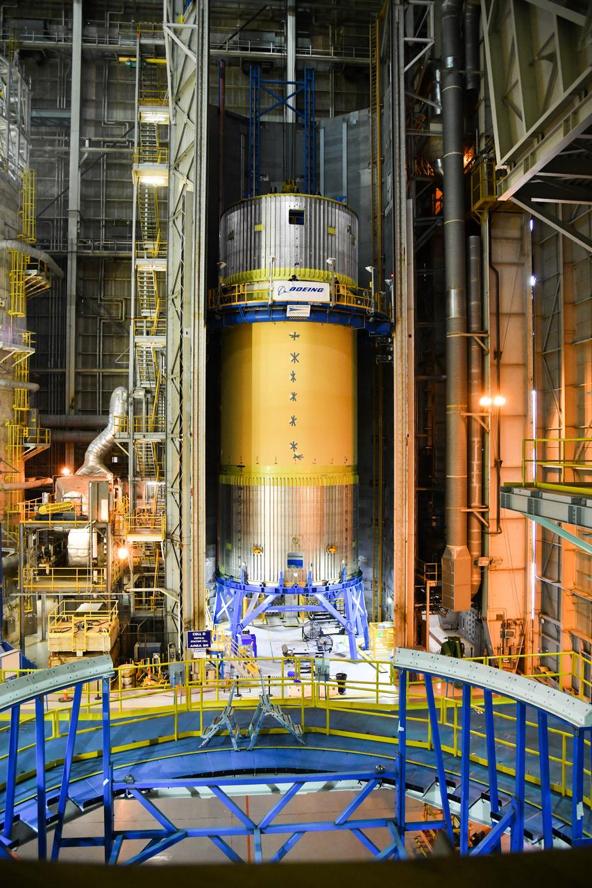
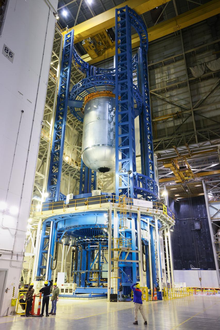
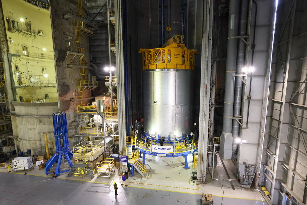
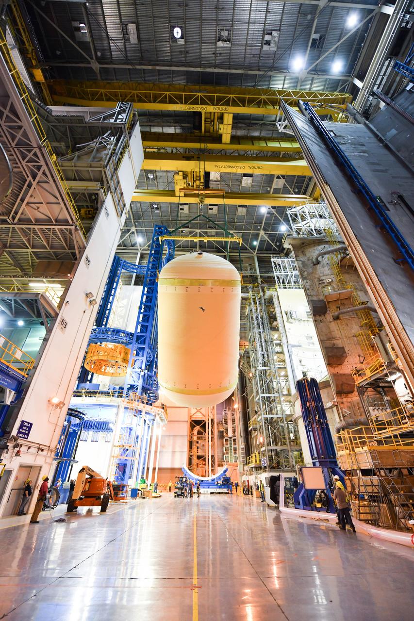
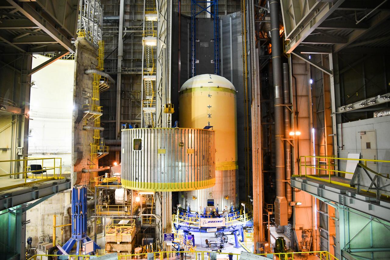
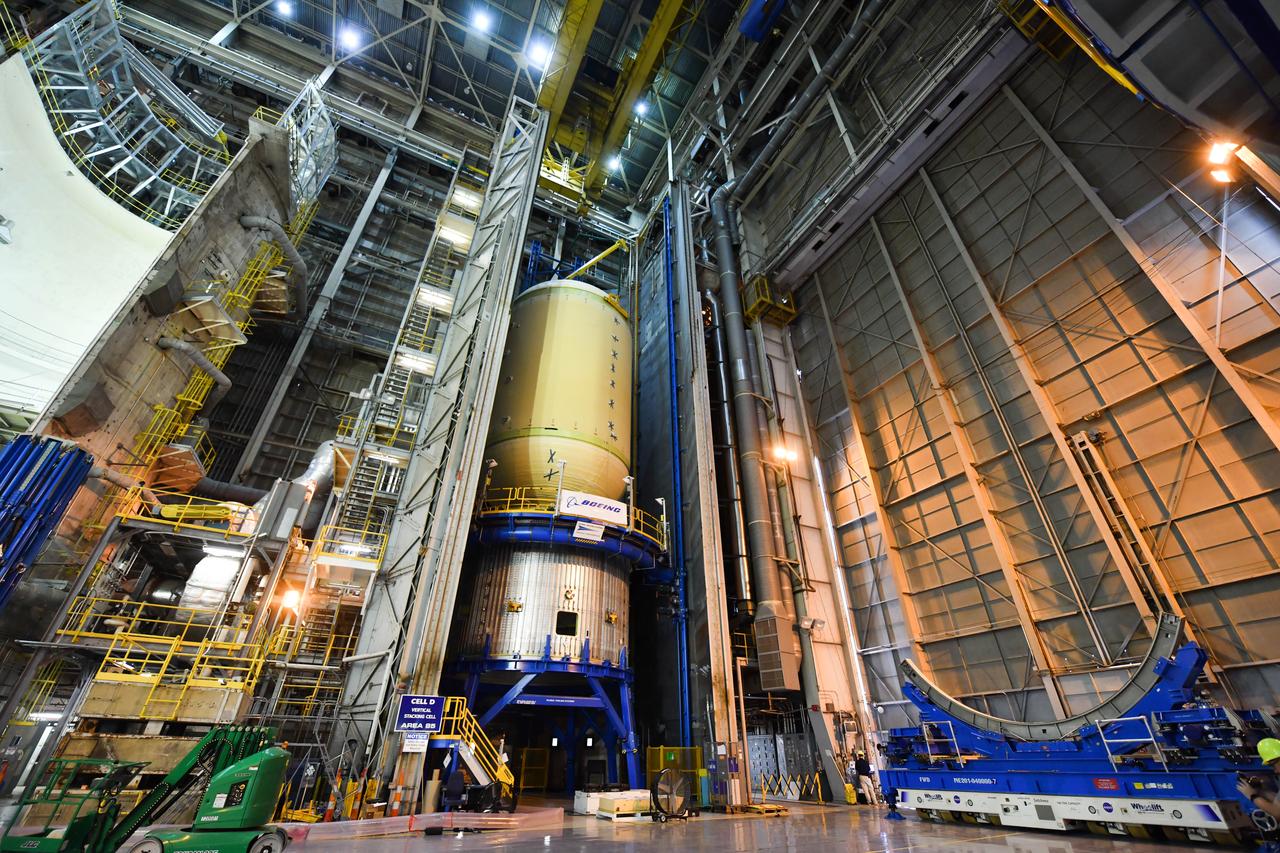
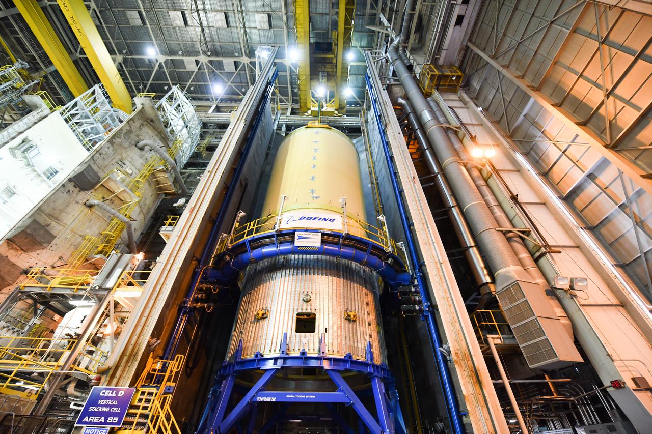
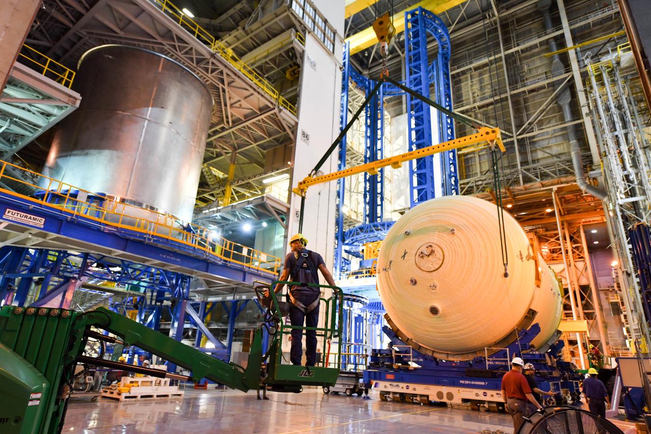
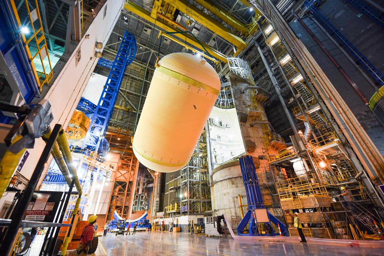
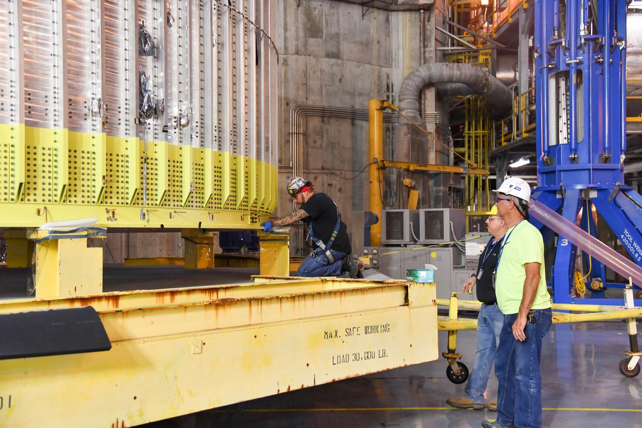
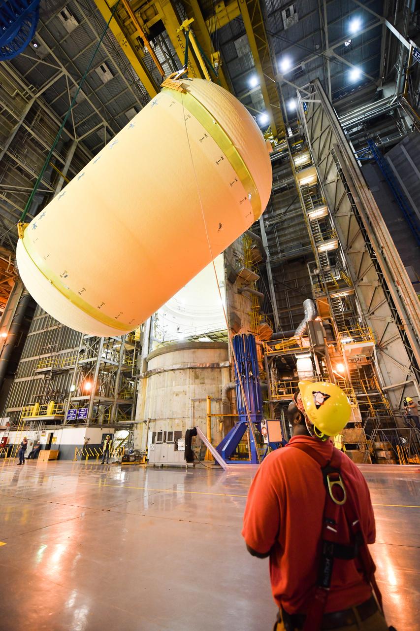
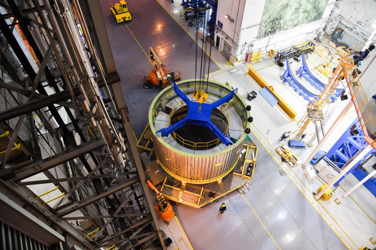
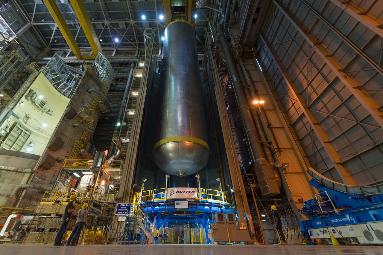
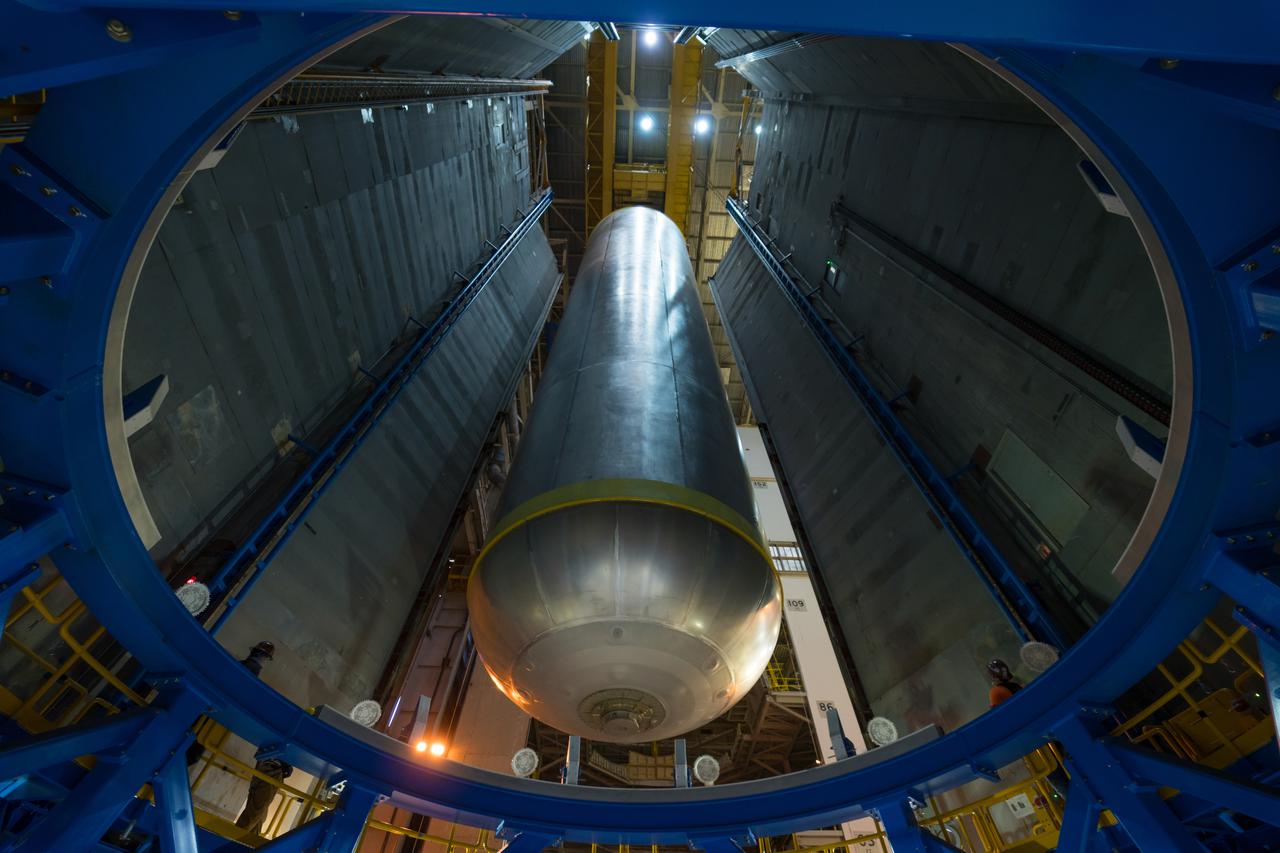
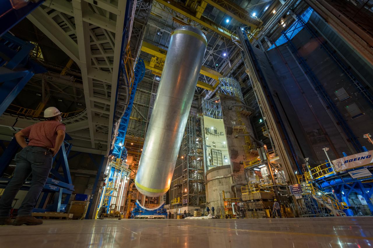
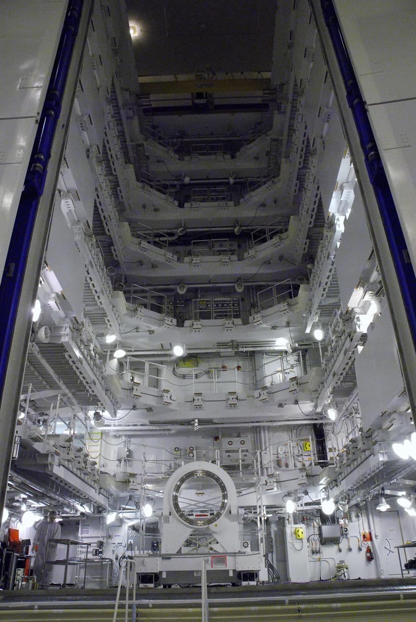
This imagery shows how technicians at NASA’s Michoud Assembly Facility in New Orleans moved the structurally complete liquid oxygen tank for NASA’s SLS (Space Launch System) after it was finished with welding Jan. 8. The tank will form part of the core stage for the SLS rocket that power NASA’s Artemis III mission to the Moon. The liquid oxygen tank is undergoing dimensional checks and partial baffle installation in Cell D. The liquid oxygen tank is one of five major components that make up the SLS rocket’s core stage. Together with the forward skirt, intertank, liquid hydrogen tank, engine section, along with the four RS-25 engines at its base, the 212-foot core stage will help power NASA’s Artemis missions to the Moon.
/MAF_20240201_CS3_LOX_VACtoCellD_07(EB)~medium.jpg)
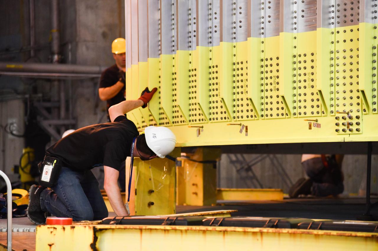
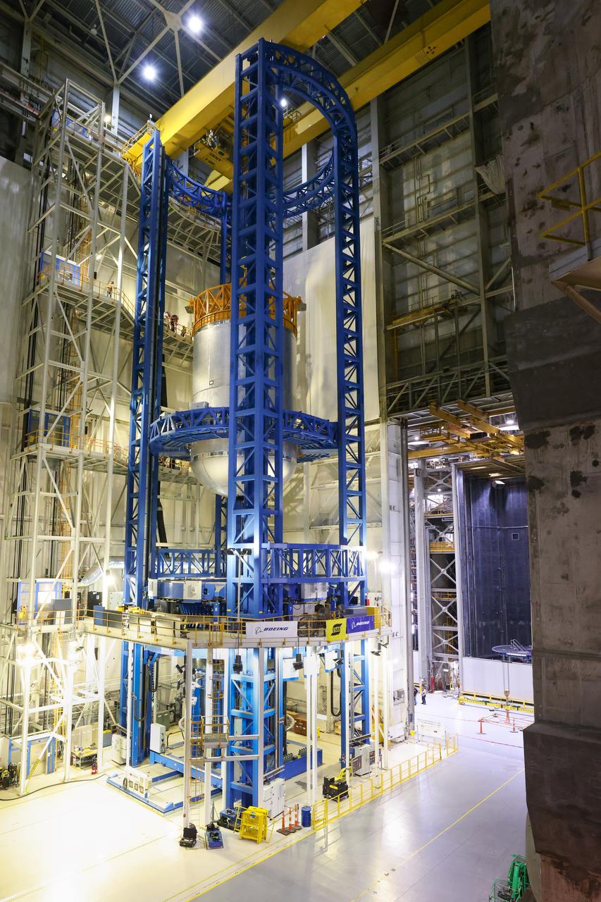
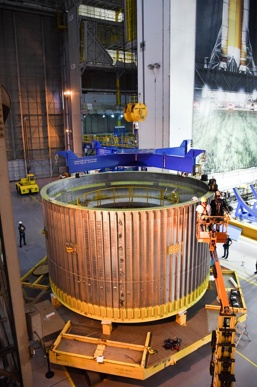
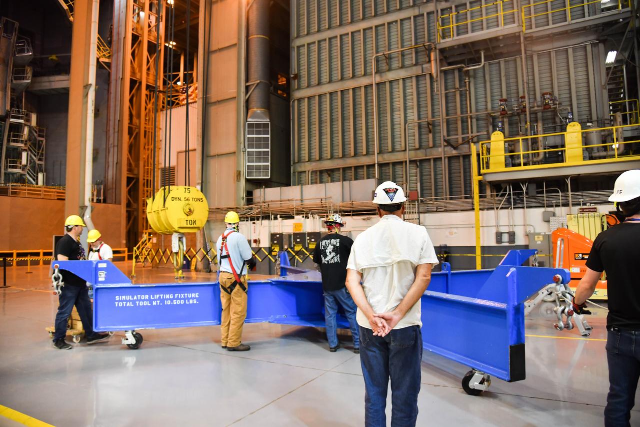
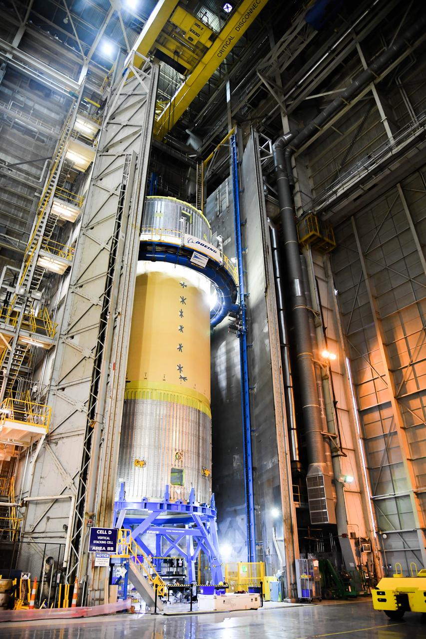
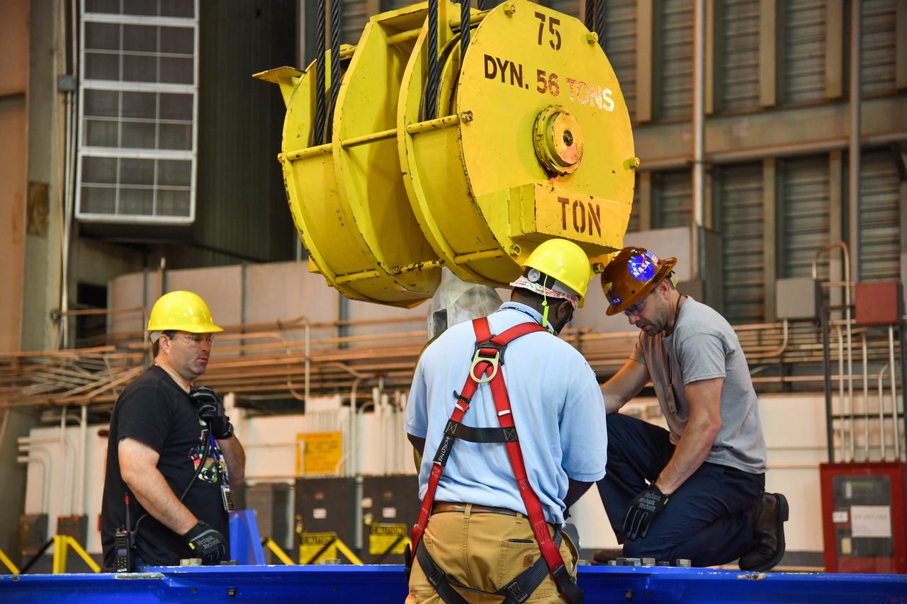
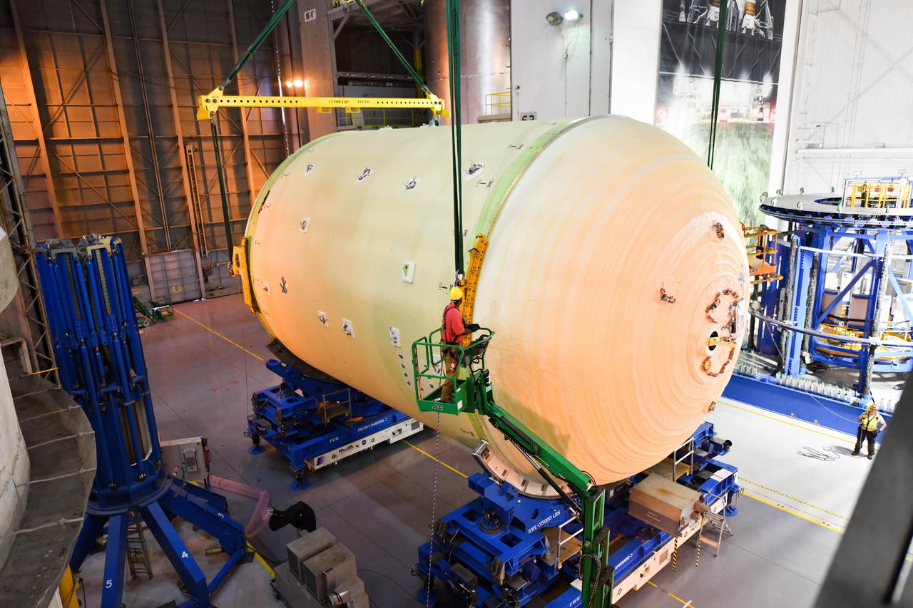
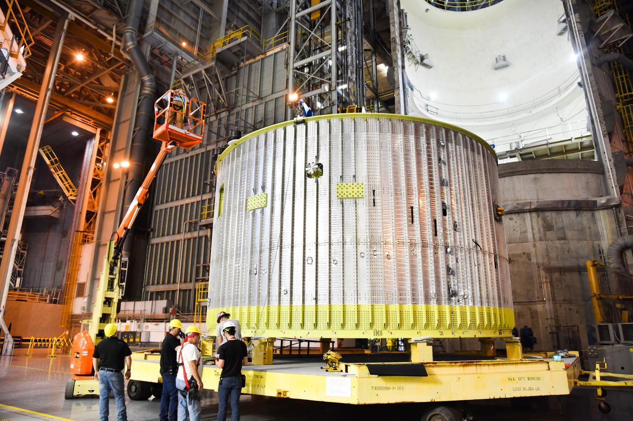
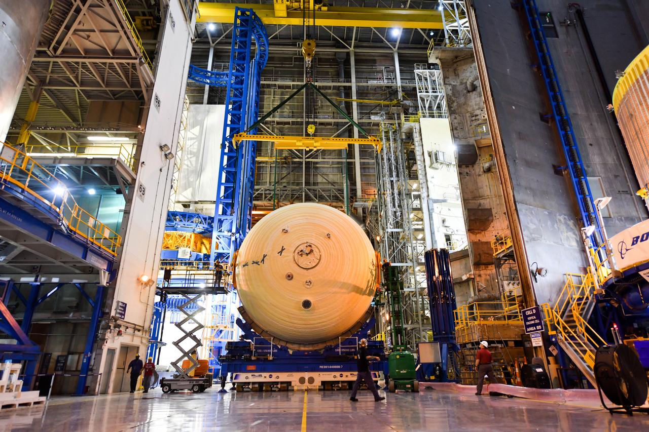
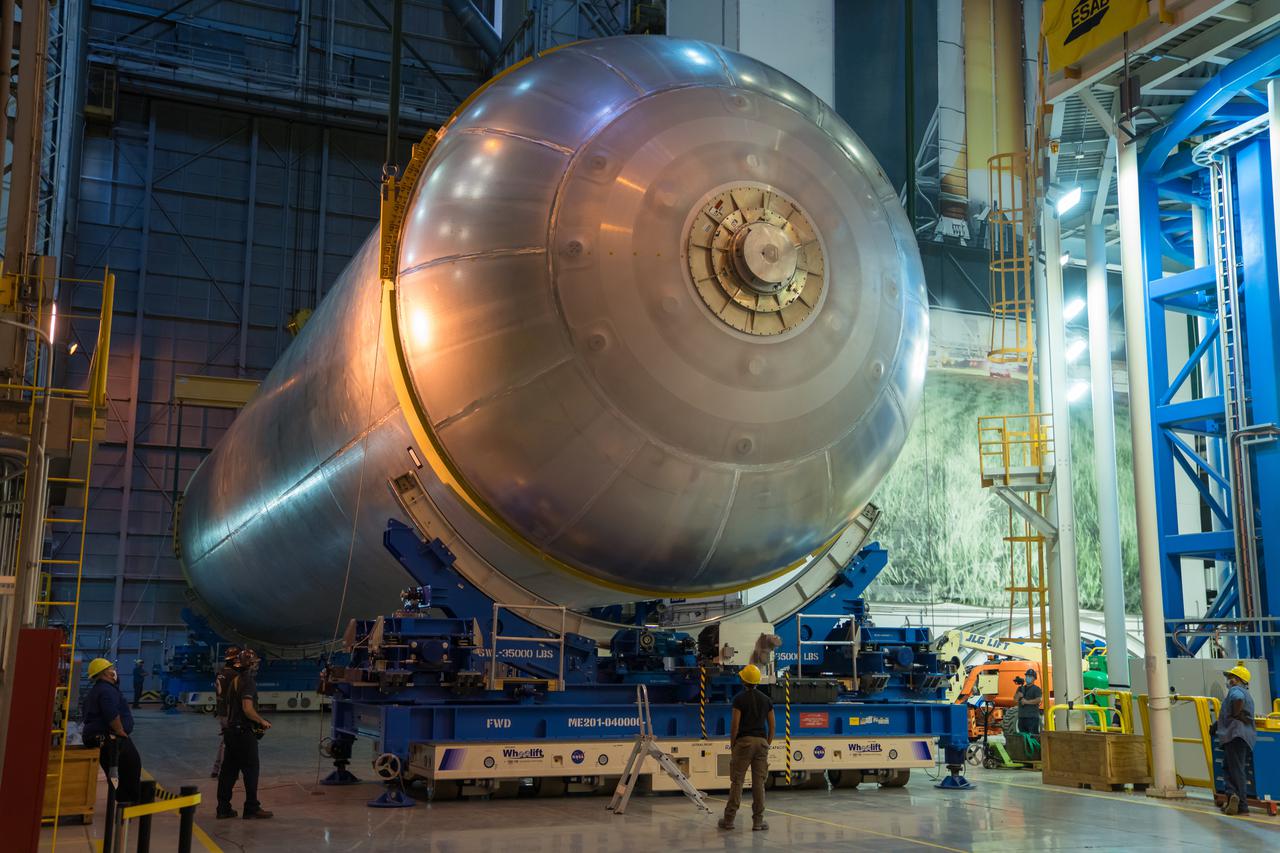
This imagery shows how technicians at NASA’s Michoud Assembly Facility in New Orleans moved the structurally complete liquid oxygen tank for NASA’s SLS (Space Launch System) after it was finished with welding Jan. 8. The tank will form part of the core stage for the SLS rocket that power NASA’s Artemis III mission to the Moon. The liquid oxygen tank is undergoing dimensional checks and partial baffle installation in Cell D. The liquid oxygen tank is one of five major components that make up the SLS rocket’s core stage. Together with the forward skirt, intertank, liquid hydrogen tank, engine section, along with the four RS-25 engines at its base, the 212-foot core stage will help power NASA’s Artemis missions to the Moon.
/MAF_20240201_CS3_LOX_VACtoCellD_03(EB)~medium.jpg)
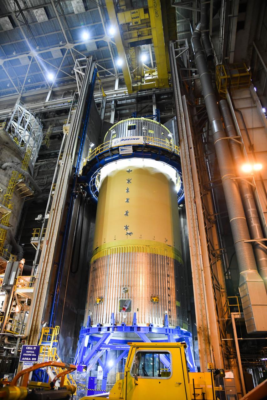
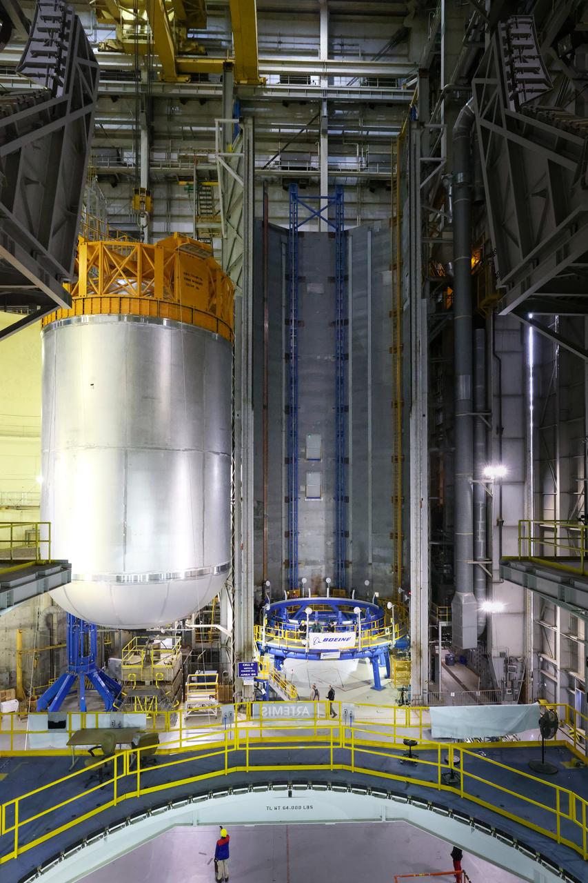
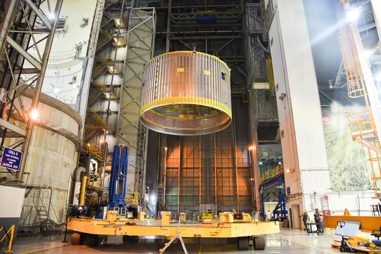
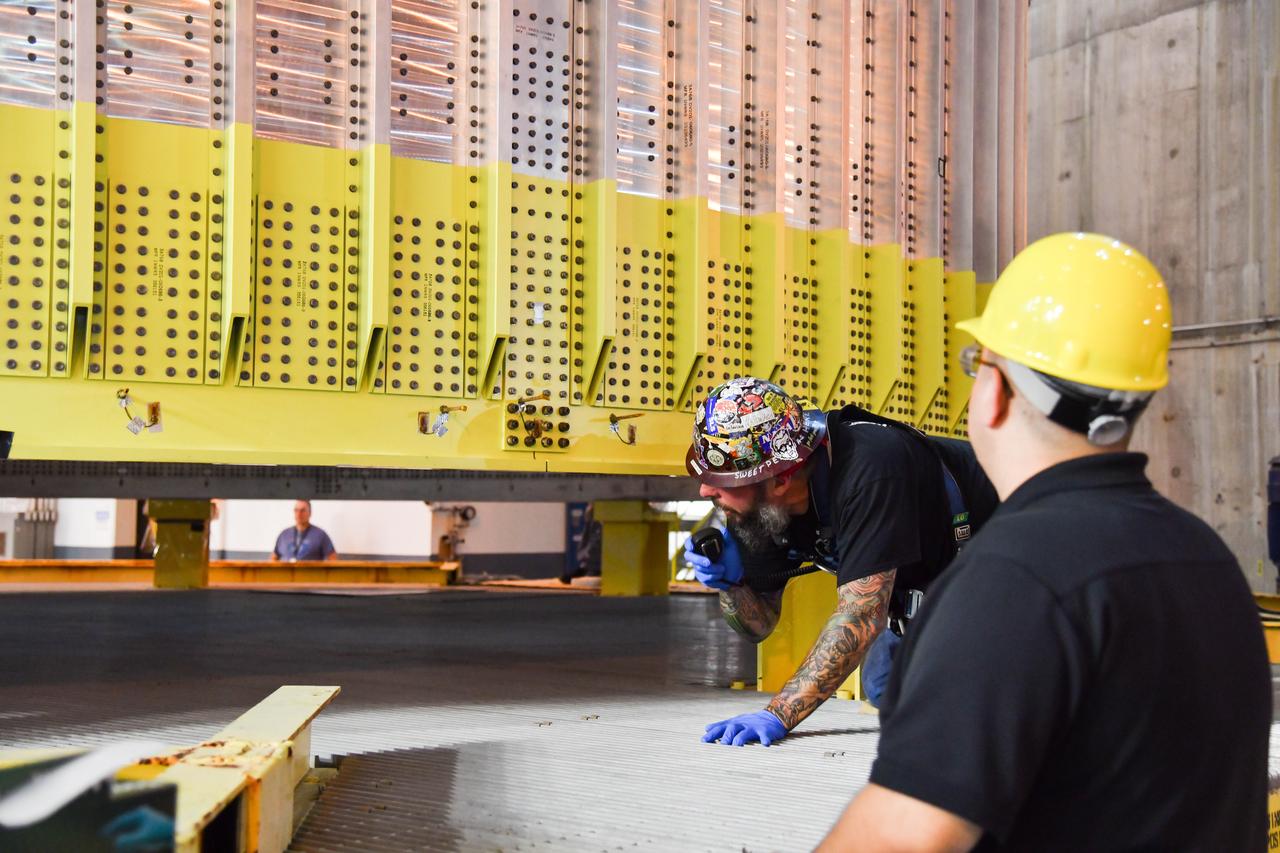
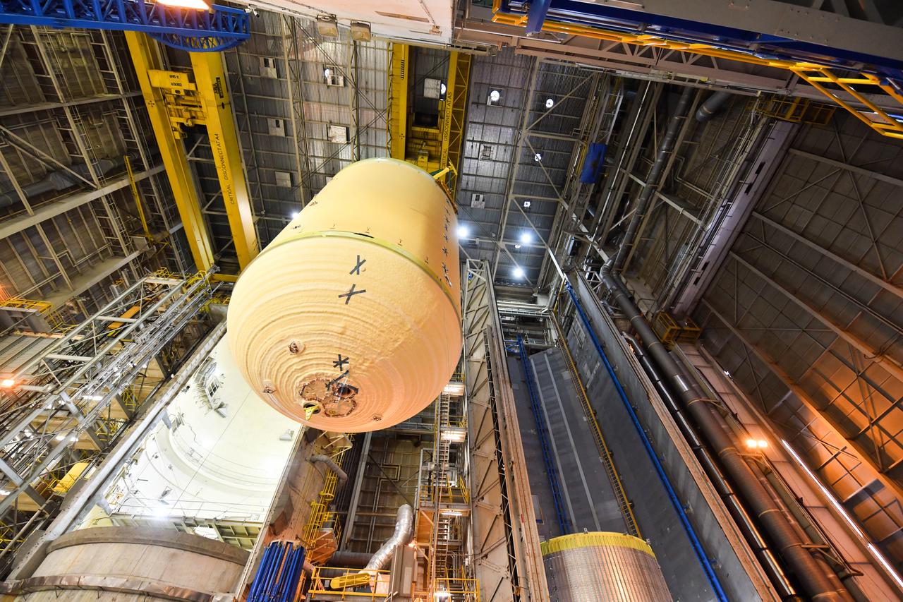
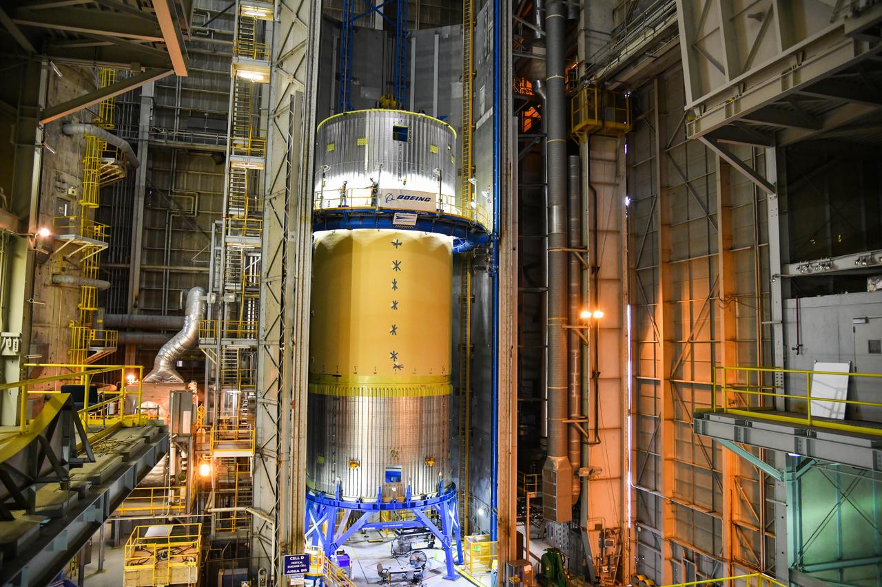
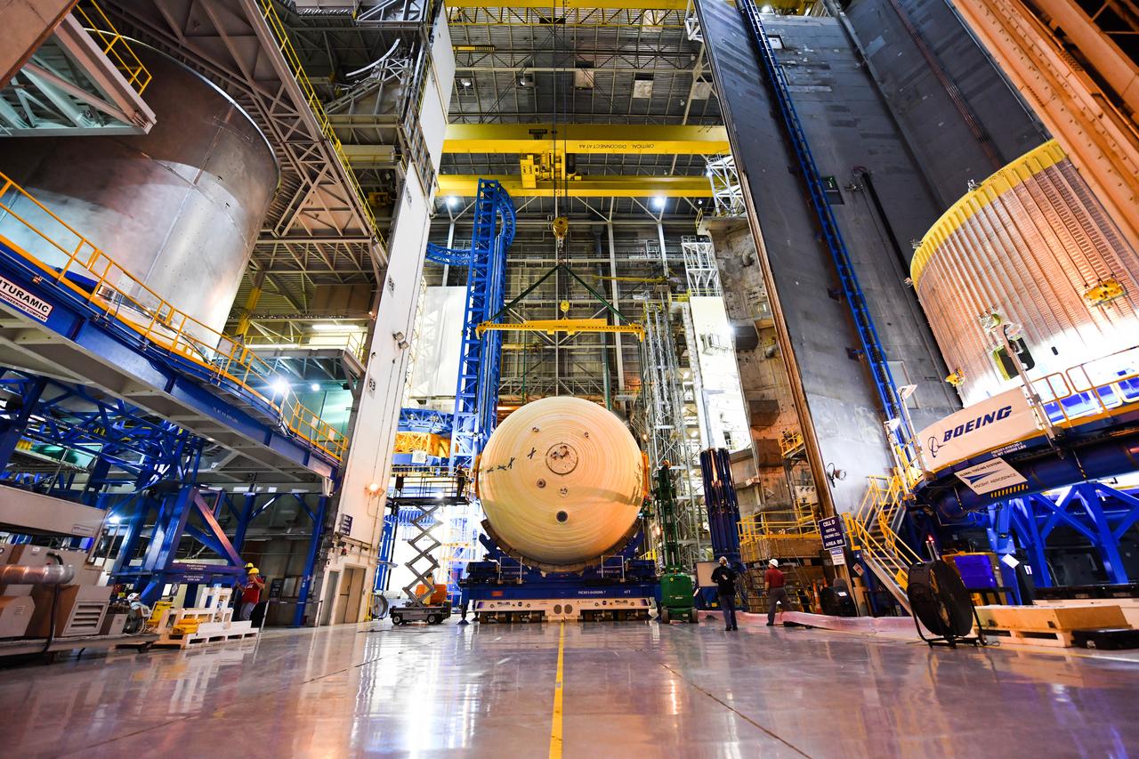
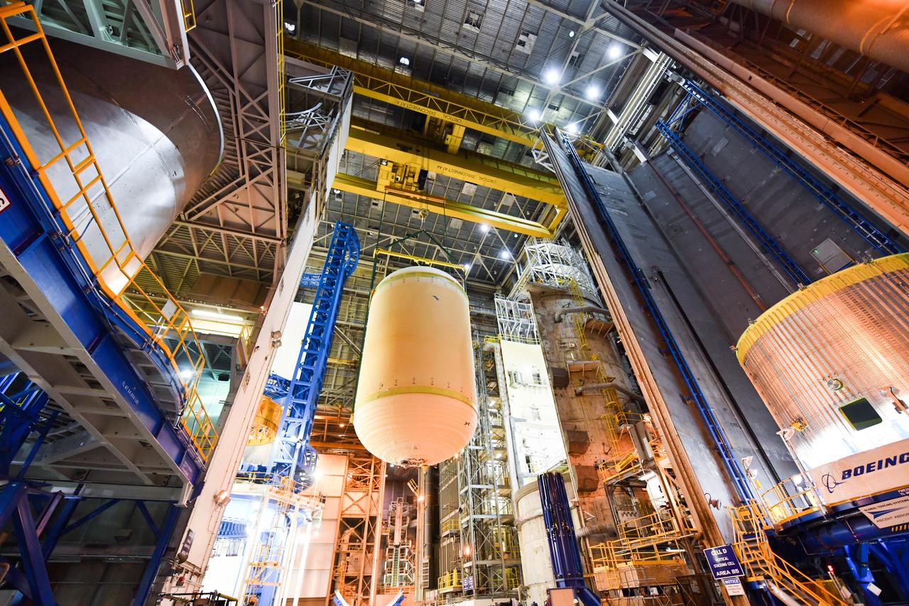
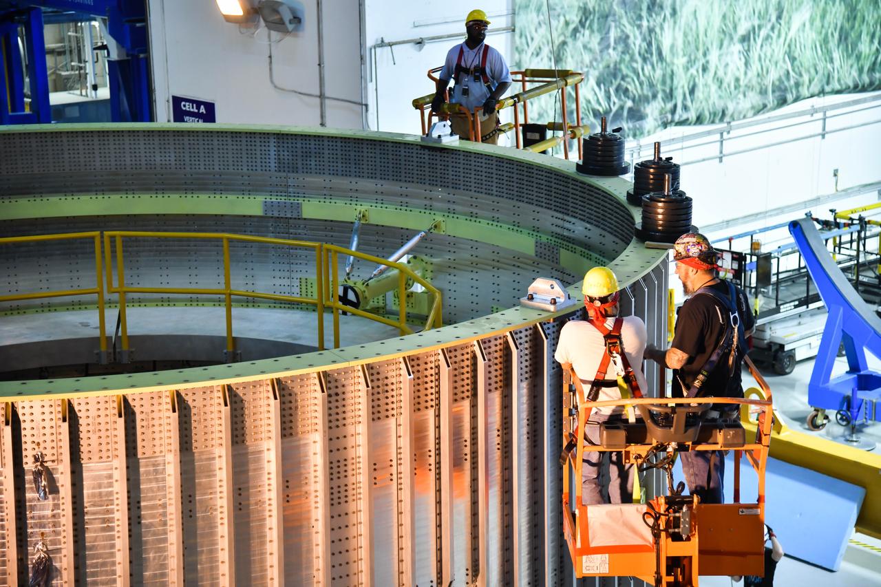
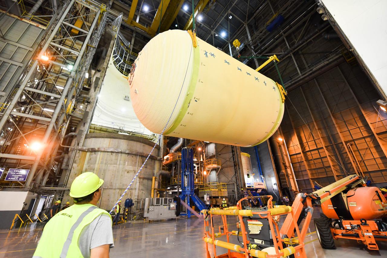
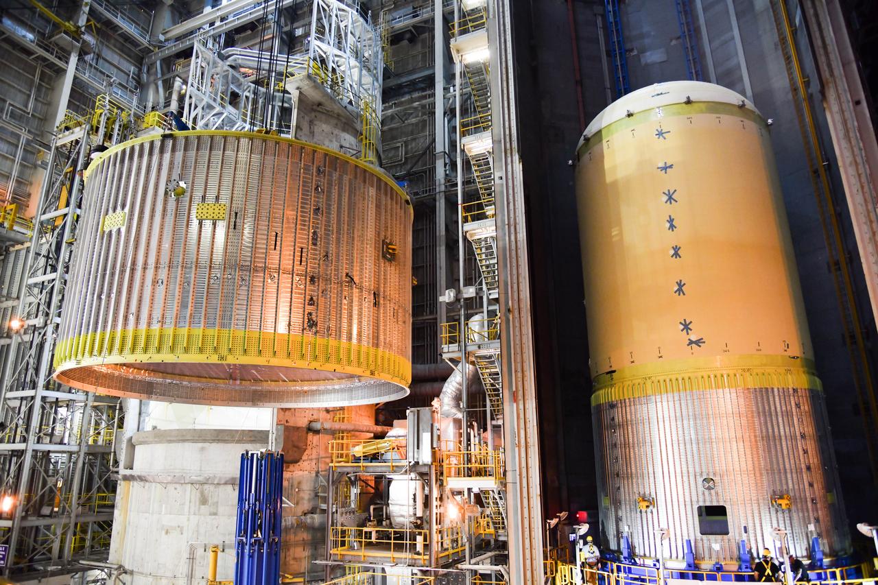
This imagery shows how technicians at NASA’s Michoud Assembly Facility in New Orleans moved the structurally complete liquid oxygen tank for NASA’s SLS (Space Launch System) after it was finished with welding Jan. 8. The tank will form part of the core stage for the SLS rocket that power NASA’s Artemis III mission to the Moon. The liquid oxygen tank is undergoing dimensional checks and partial baffle installation in Cell D. The liquid oxygen tank is one of five major components that make up the SLS rocket’s core stage. Together with the forward skirt, intertank, liquid hydrogen tank, engine section, along with the four RS-25 engines at its base, the 212-foot core stage will help power NASA’s Artemis missions to the Moon.
/MAF_20240201_CS3_LOX_VACtoCellD_02(EB)~medium.jpg)
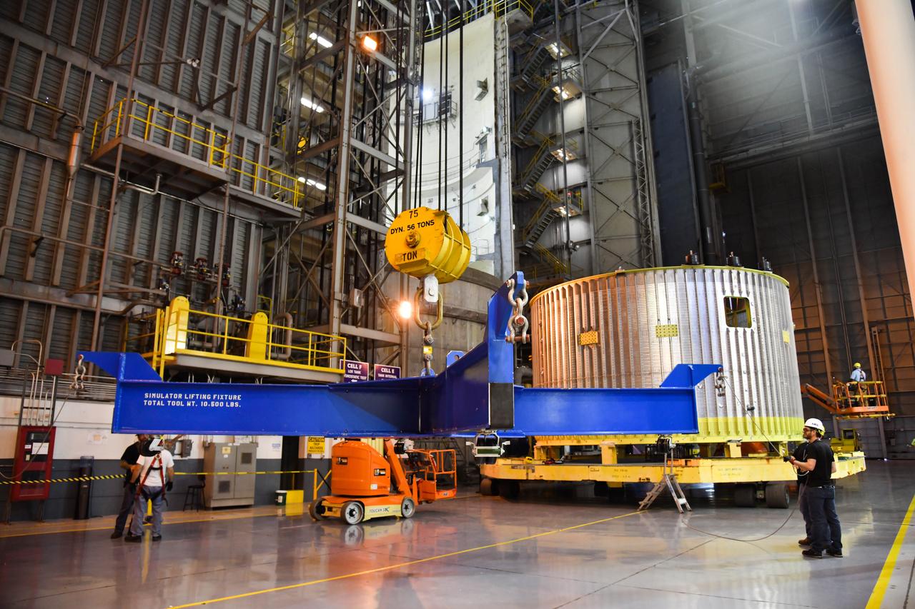
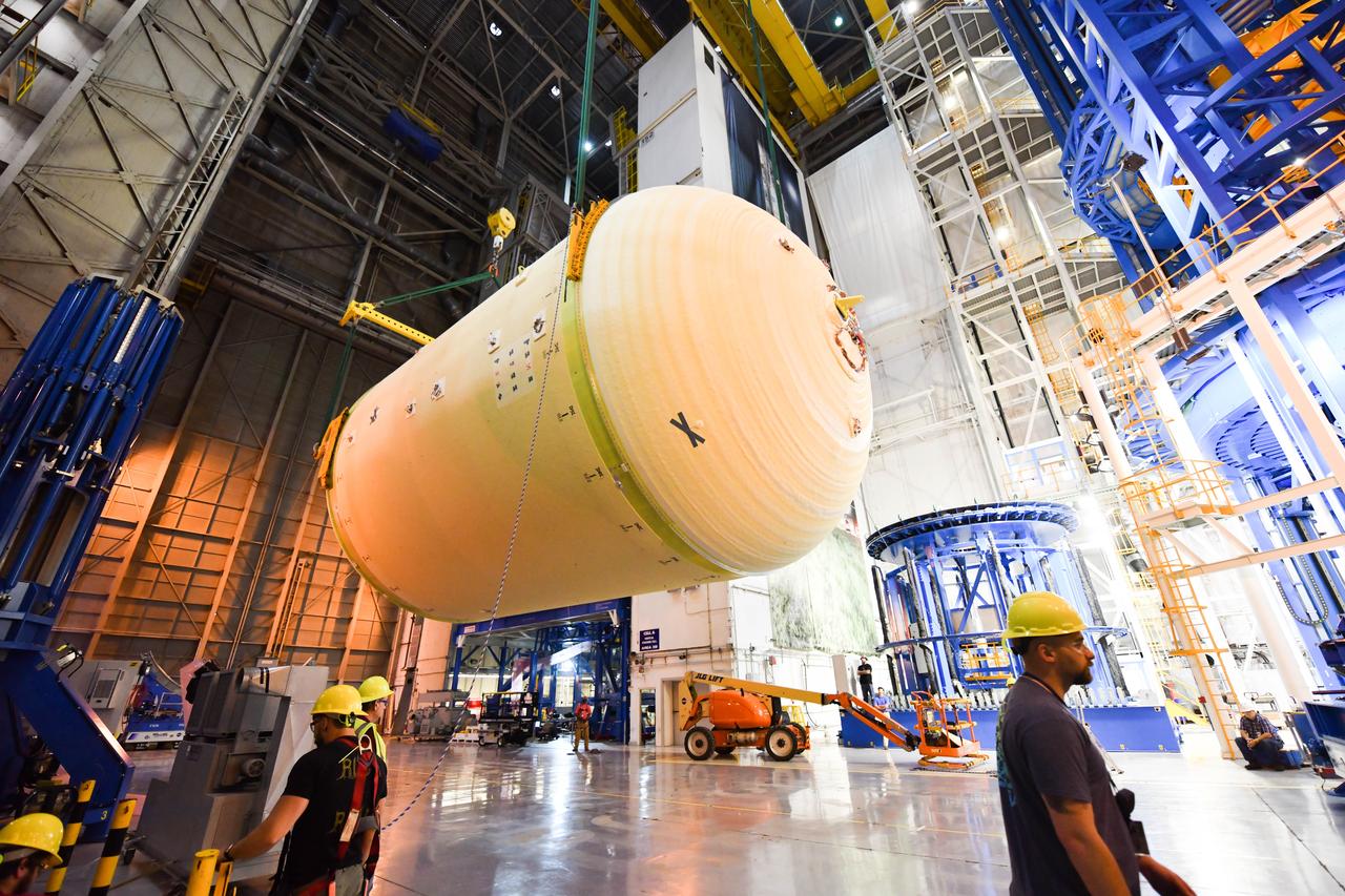
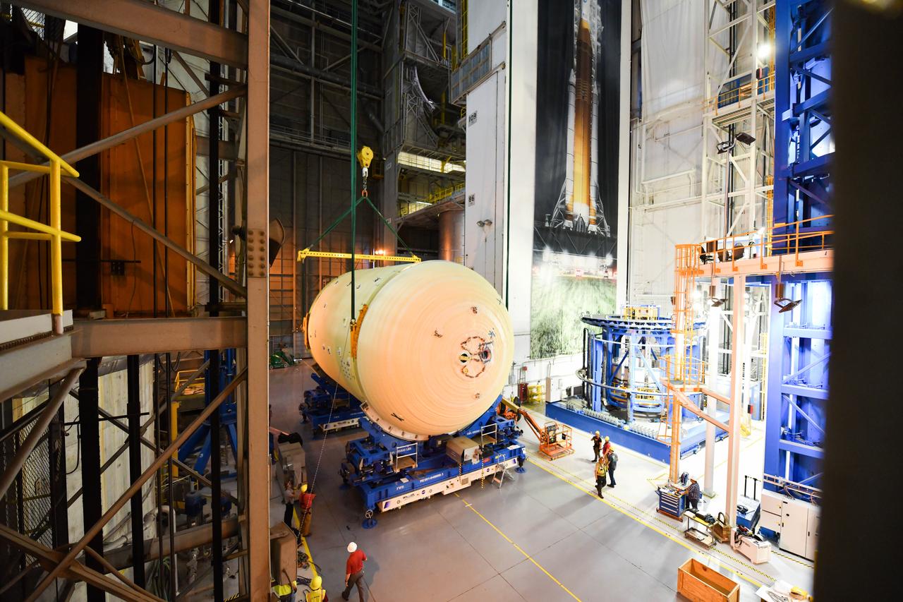
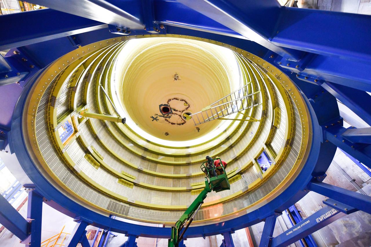
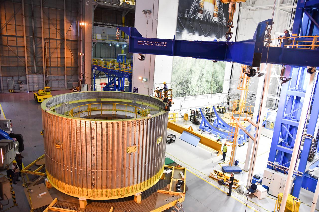
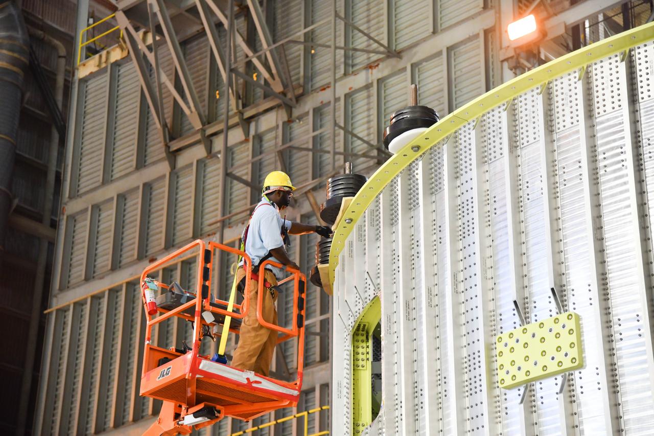
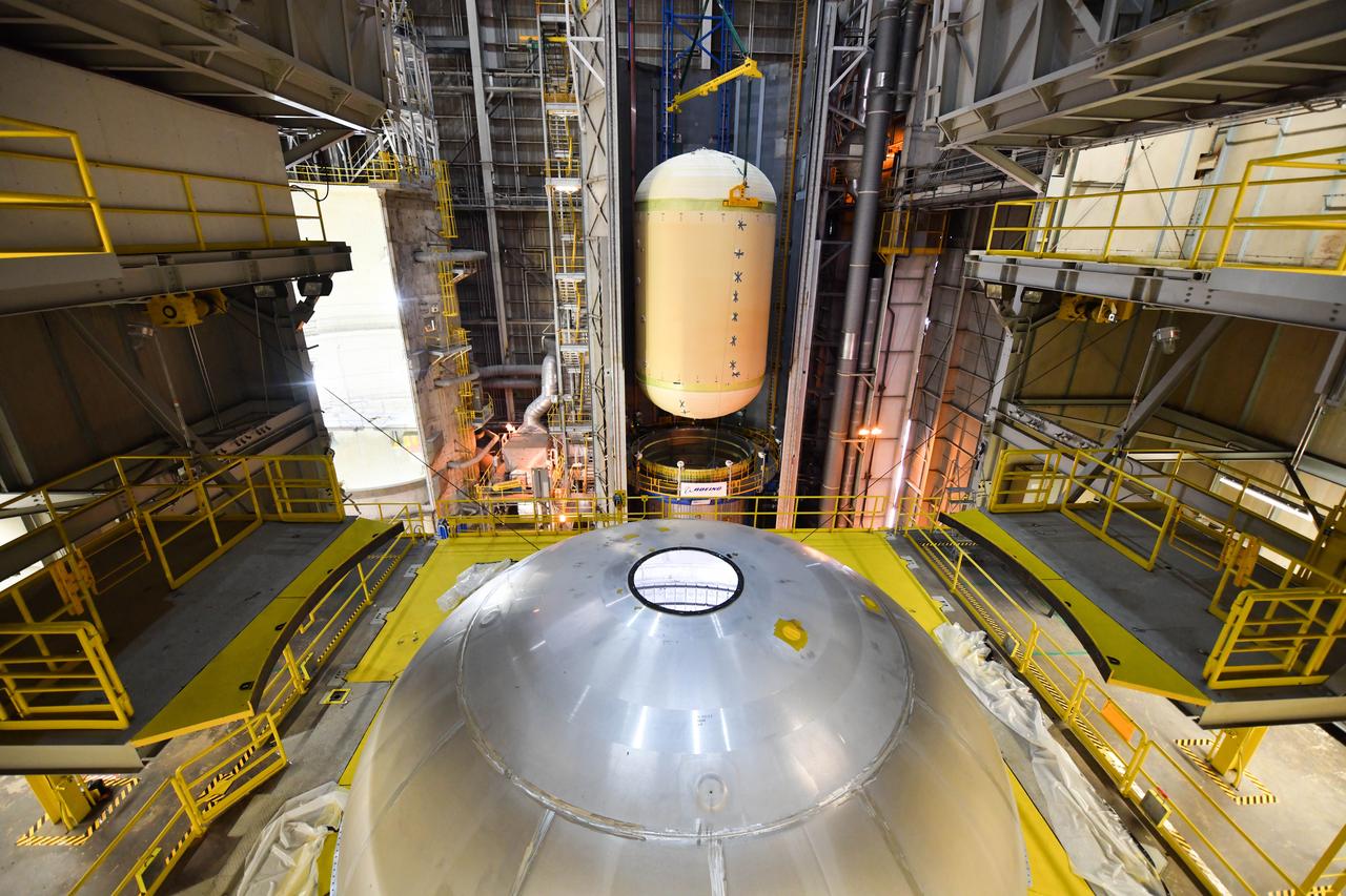
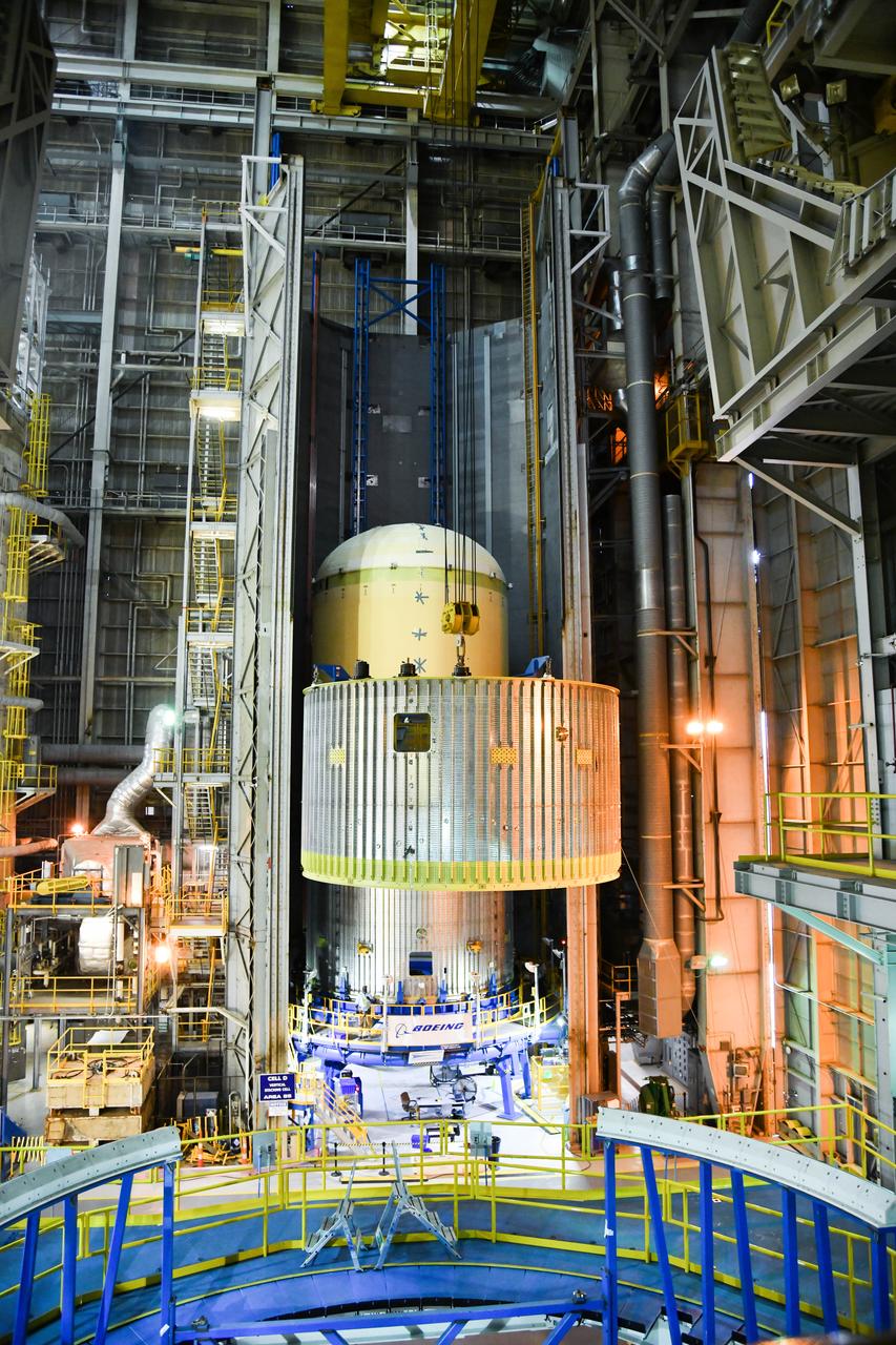
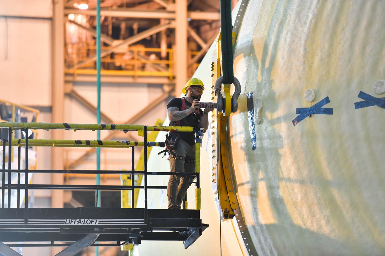
This imagery shows how technicians at NASA’s Michoud Assembly Facility in New Orleans moved the structurally complete liquid oxygen tank for NASA’s SLS (Space Launch System) after it was finished with welding Jan. 8. The tank will form part of the core stage for the SLS rocket that power NASA’s Artemis III mission to the Moon. The liquid oxygen tank is undergoing dimensional checks and partial baffle installation in Cell D. The liquid oxygen tank is one of five major components that make up the SLS rocket’s core stage. Together with the forward skirt, intertank, liquid hydrogen tank, engine section, along with the four RS-25 engines at its base, the 212-foot core stage will help power NASA’s Artemis missions to the Moon.
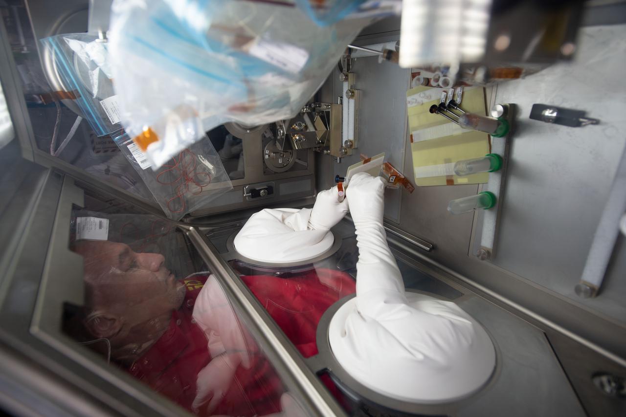
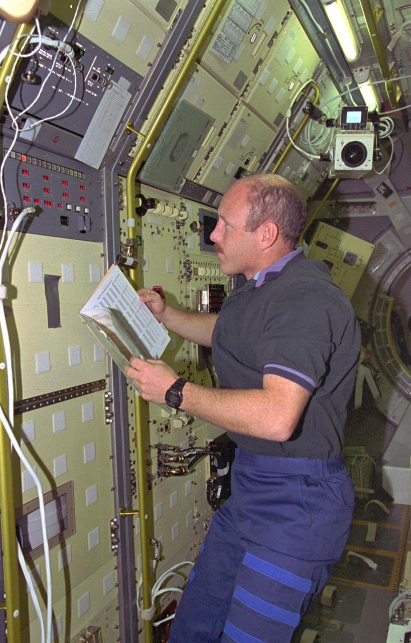
iss060e035085 (8/12/2019) --- European Space Agency (ESA) astronaut Luca Parmitano injects media into the culture bag of the Micro-15 investigation in the Japanese Experiment Module (JEM) abroad the International space Station (ISS). The goal of this investigation is to better understand the effects of gravity on the differentiation of mammalian cells using 3-D cultures of induced pluripotent stem (iPS) cells. This study investigates how exposure to microgravity fundamentally alters cell regulation and how these changes can affect the timing, progression, and outcomes of cell differentiation.
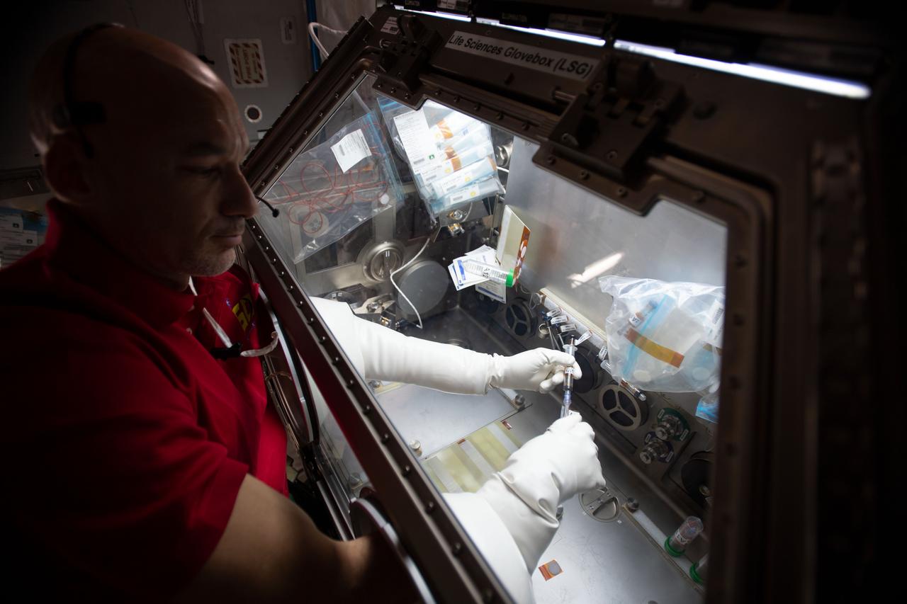
iss060e035097 (8/12/2019) --- European Space Agency (ESA) astronaut Luca Parmitano injects media into the culture bag of the Micro-15 investigation in the Japanese Experiment Module (JEM) abroad the International space Station (ISS). The goal of this investigation is to better understand the effects of gravity on the differentiation of mammalian cells using 3-D cultures of induced pluripotent stem (iPS) cells. This study investigates how exposure to microgravity fundamentally alters cell regulation and how these changes can affect the timing, progression, and outcomes of cell differentiation.

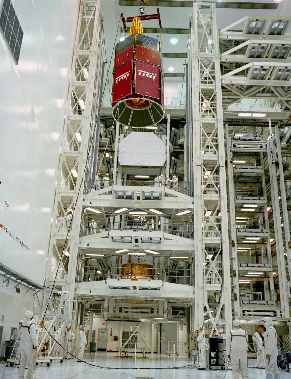
S89-28093 (29 Dec 1988) --- In the clean room of the vertical processing facility, the TDRS-D satellite is hoisted, thus beginning the mating process with the inertial upper stage (IUS), located in an adjacent test cell.
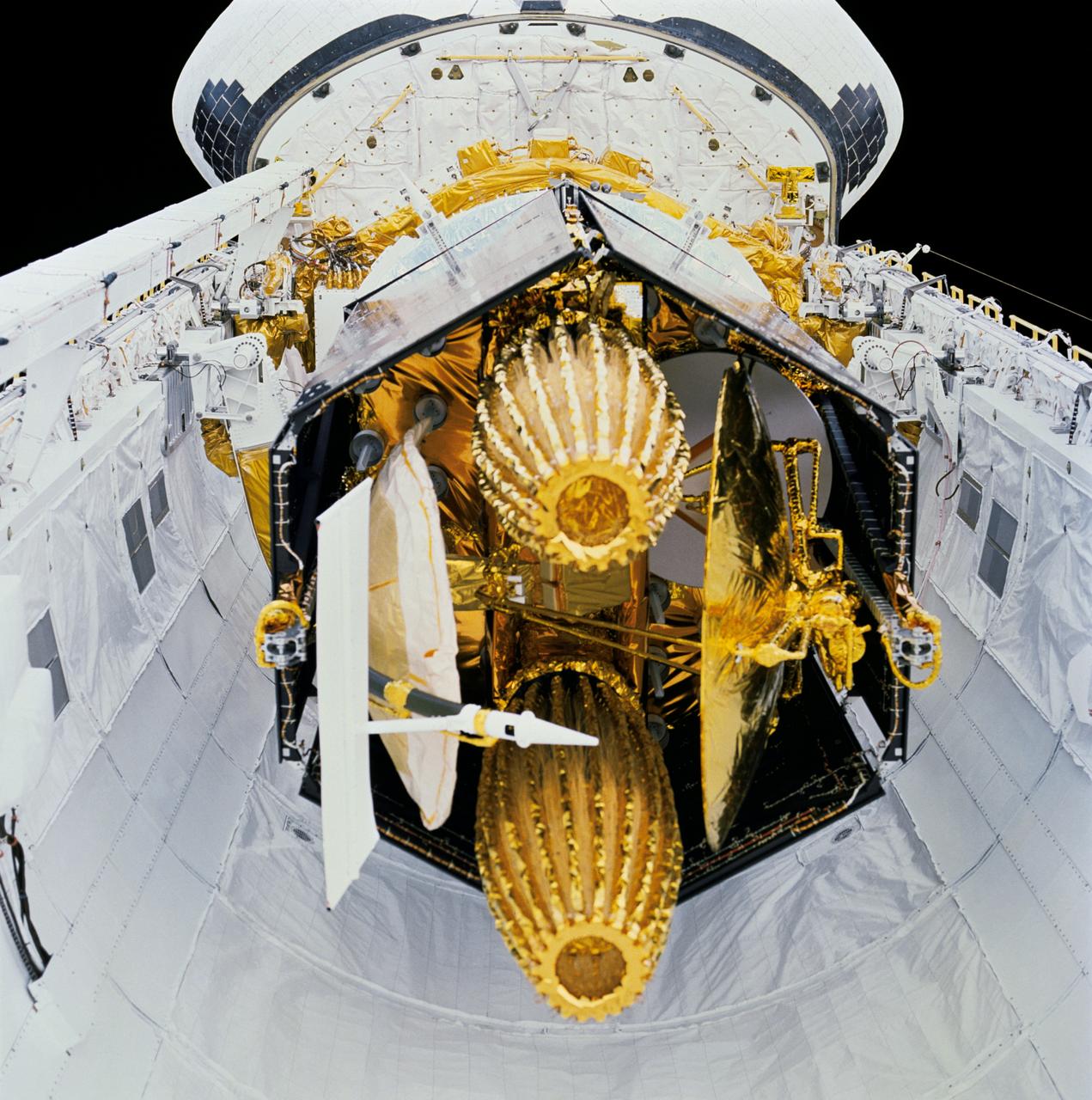
STS029-71-000AE (13-18 March 1989) --- STS-29 onboard view shows Space Shuttle Discovery's payload bay with tracking and data relay satellite D (TDRS-D) in stowed, pre-deployment position. In this head-on view, TDRS-D stowed components including single access #1 and #2, solar cell panels, SGL, S-Band omni antenna, and C-Band antenna are visible. TDRS-D rests in airborne support equipment (ASE) forward cradle and aft frame tilt actuator (AFTA). Discovery's aft bulkhead and orbital maneuvering system (OMS) pods are visible in the background.
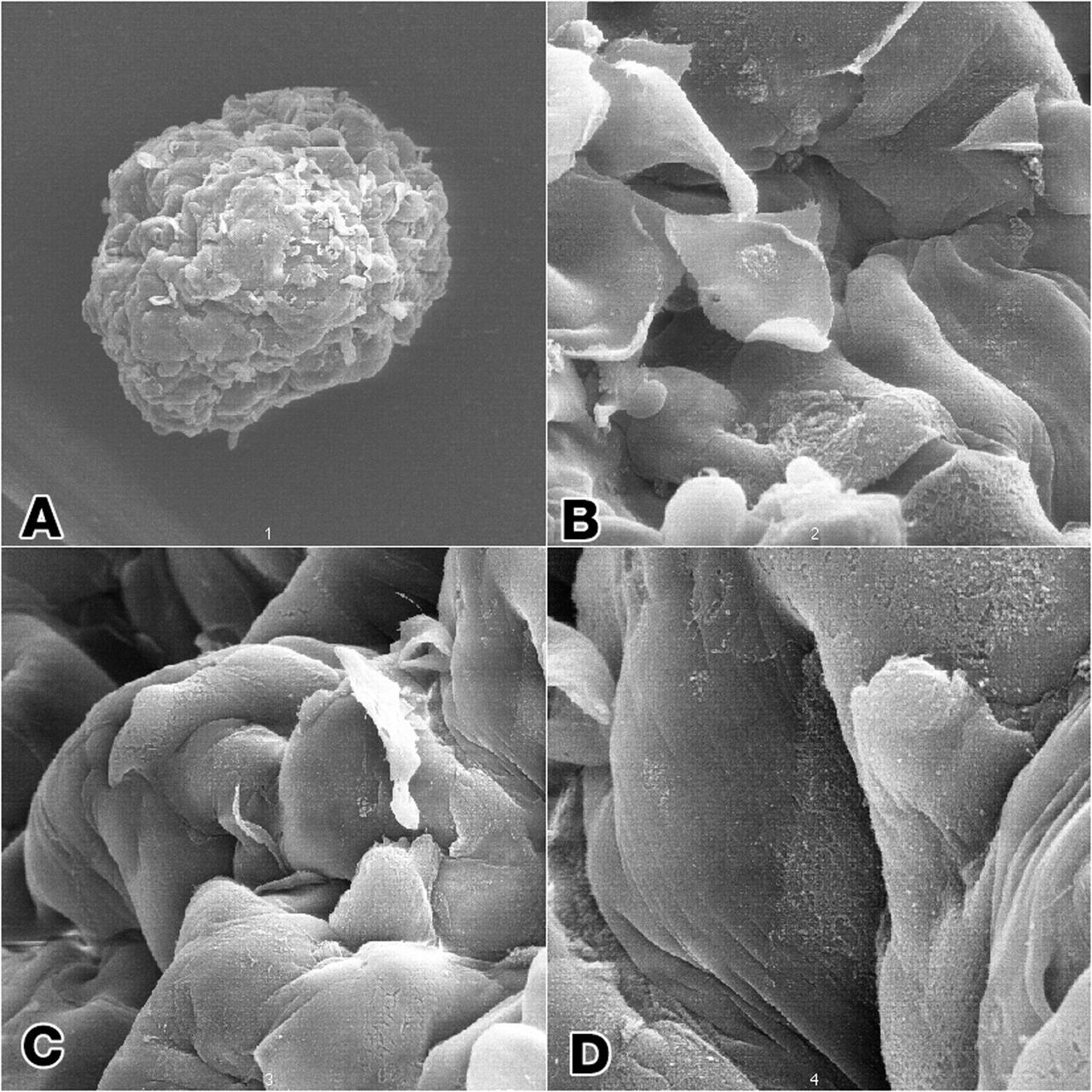
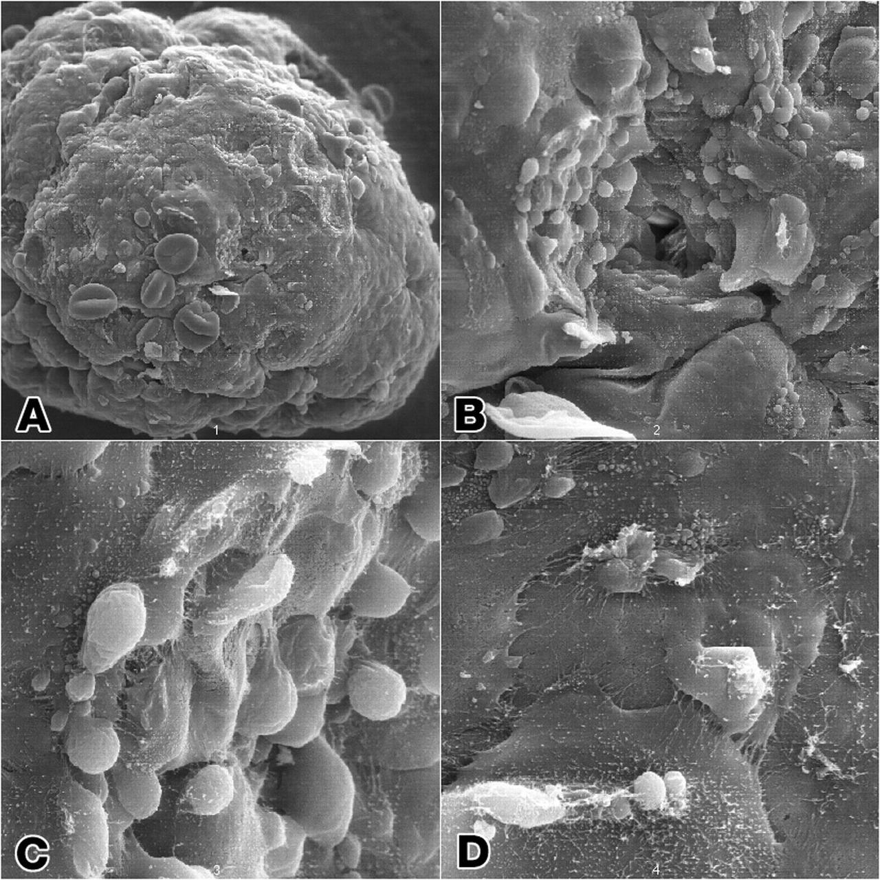
Epithelial and fibroblast cell coculture: Long-term growth human mammary epithelial cells (HMEC) admixed in coculture with fibroblast from the same initial breast tissue grown as 3-dimenstional constructions in the presence of attachment beads in the NASA Bioreactor. A: A typical constrct about 2.0 mm in diameter without beads on the surface. The center of these constrcts is hollow, and beads are organized about the irner surface. Although the coculture provides smaller constructs than the monoculture, the metabolic of the organized cells is about the same. B, C, D: Closer views of cells showing that the shape of cells and cell-to-cell interactions apprear different in the coculture than in the monoculture constructs. NASA's Marshall Space Flight Center (MSFC) is sponsoring research with Bioreactors, rotating wall vessels designed to grow tissue samples in space, to understand how breast cancer works. This ground-based work studies the growth and assembly of human mammary epithelial cell (HMEC) from breast cancer susceptible tissue. Radiation can make the cells cancerous, thus allowing better comparisons of healthy vs. tunorous tissue. Credit: Dr. Robert Richmond, NASA/Marshall Space Flight Center (MSFC).

Isolation of human mammary epithelial cells (HMEC) from breast cancer susceptible tissue; A: Duct element recovered from breast tissue digest. B: Outgrowth of cells from duct element in upper right corner cultured in a standard dish; most cells spontaneousely die during early cell divisions, but a few will establish long-term growth. C: Isolate of long-term frowth HMEC from outgrowth of duct element; cells shown soon after isolation and in early full-cell contact growth in culture in a dish. D: same long-term growth HMEC, but after 3 weeks in late full-cell contact growth in a continuous culture in a dish. Note attempts to reform duct elements but this in two demensions in a dish rather than in three dimensions in tissue. NASA's Marshall Space Flight Center (MSFC) is sponsoring research with Bioreactors, rotating wall vessels designed to grow tissue samples in space, to understand how breast cancer works. This ground-based work studies the growth and assembly of human mammary epithelial cell (HMEC) from breast cancer susceptible tissue. Radiation can make the cells cancerous, thus allowing better comparisons of healthy vs. tunorous tissue. Credit: Dr. Robert Richmond, NASA/Marshall Space Flight Center (MSFC).
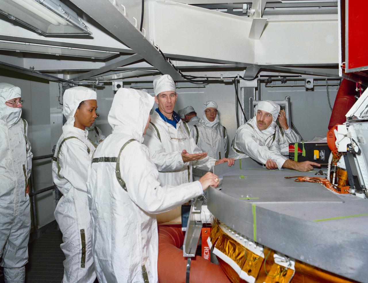
S89-28108 --- Astronaut Mae C. Jemison and STS-29 Mission Specialist James P. Bagian and Robert C. Springer inspect the interface between the tracking and data relay satellite D (TDRS-D) and inertial upper stage (IUS-9) in a test cell located in the Kennedy Space Center (KSC) Vertical Processing Facility (VPF). The clean-suited astronauts, engineers, and technicians discuss the payload. Photo credit: NASA

Epithelial cell monoculture: Long-term growth of human mammary epithelial cells (HMEC) grown in monoculture as 3-dimensional constructions in the presence of attachment beads in the NASA Bioreactor. A: A typical construct about 3.5 mm (less than 1/8th inch) in diameter with slightly dehydrted, crinkled beads contained on the surface as well as within the 3-dimensional structure. B: The center of these constructs is hollow. Crinkling of the beads causes a few to fall out, leaving crater-like impressiions in the construct. The central impression shows a small hole that accesses the hollow center of the construct. C: A closeup view of the cells and the hole the central impression. D: Closer views of cells in the construct showing sell-to-cell interactions. NASA's Marshall Space Flight Center (MSFC) is sponsoring research with Bioreactors, rotating wall vessels designed to grow tissue samples in space, to understand how breast cancer works. This ground-based work studies the growth and assembly of human mammary epithelial cell (HMEC) from breast cancer susceptible tissue. Radiation can make the cells cancerous, thus allowing better comparisons of healthy vs. tunorous tissue. Credit: Dr. Robert Richmond, NASA/Marshall Space Flight Center (MSFC).

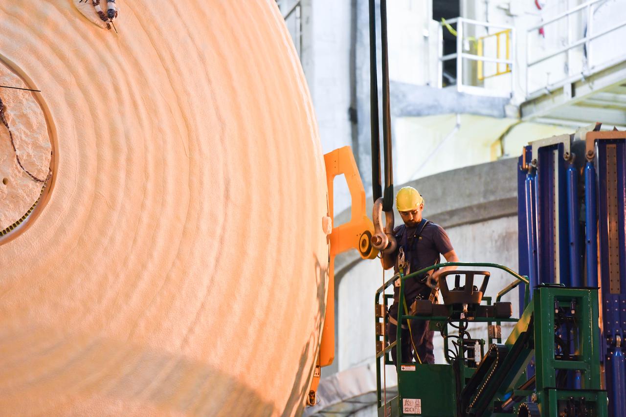
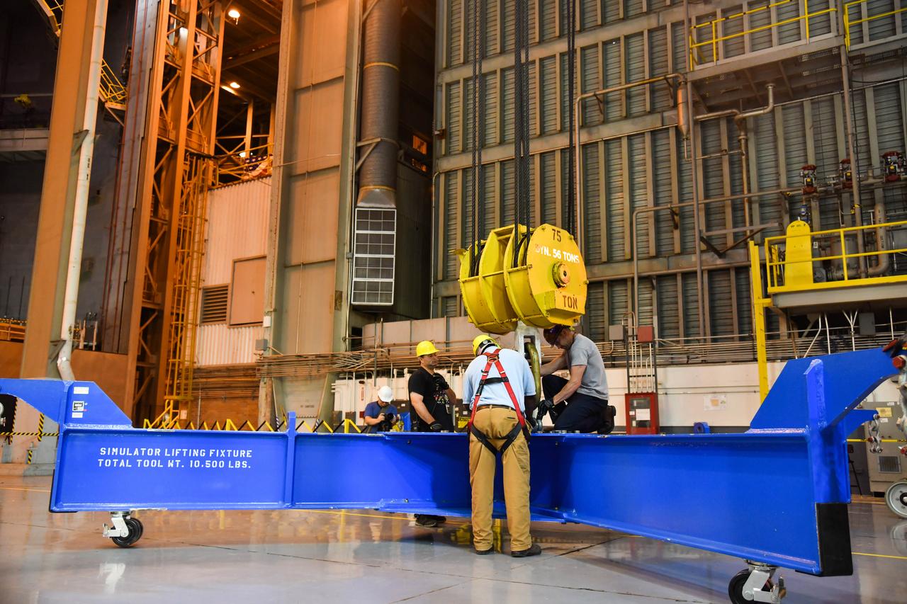
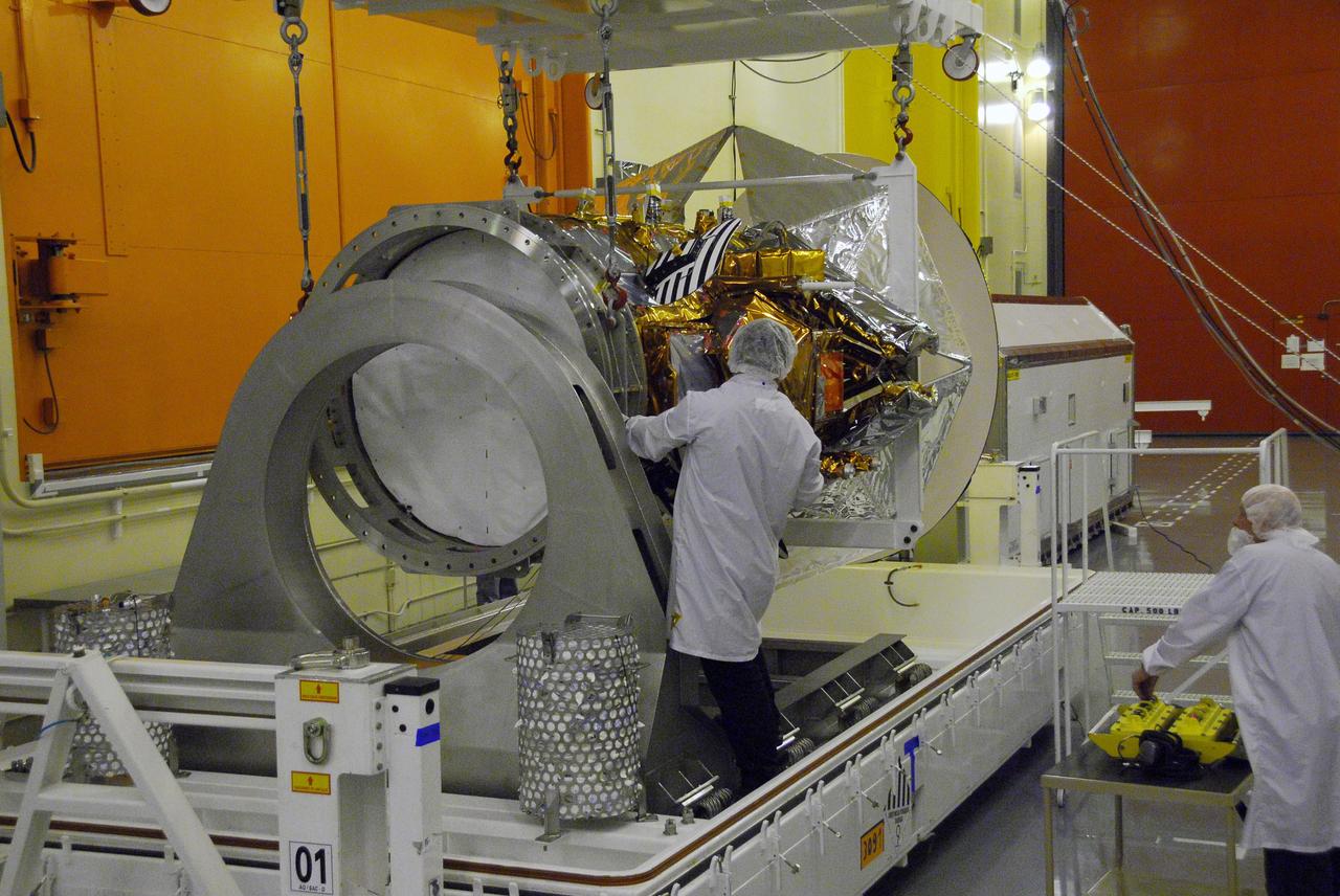
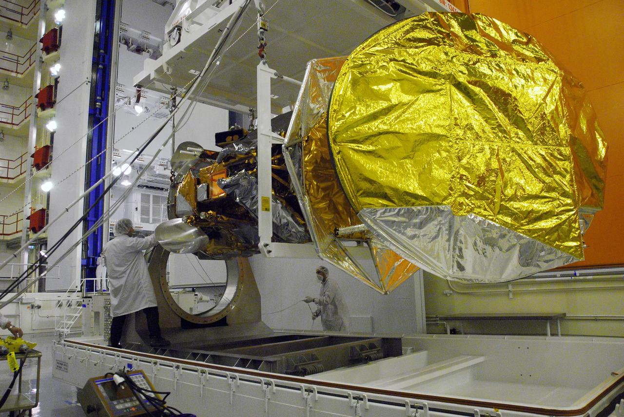
The Space Launch System (SLS) rocket’s liquid oxygen tank structural test article was manufactured and stacked in June 2019 at NASA’s Michoud Assembly Facility in New Orleans. To construct the test article, Boeing technicians at Michoud moved the liquid oxygen tank to the Vertical Assemby Building stacking and integration area. Here, they added simulators to mimic the two structures that connect to the tank, the intertank and the forward skirt. This structural hardware for the SLS core stage for America’s new deep space rocket is structurally identical to the flight version of the tank. It will be shipped on the Pegasus barge to NASA’s Marshall Space Flight Center in Hunstville, Alabama, where it will undergo a series of tests that simulate the stresses and loads of liftoff and flight. These tests will help ensure designs are adequate for successful SLS missions to the Moon and beyond. The flight liquid oxygen tank along with the liquid hydrogen tank supplies more than 500,000 gallons of propellant to the core stages four RS-25 engines, which produce 2 million pounds of thrust to help send the SLS rocket to space.
The Space Launch System (SLS) rocket’s liquid oxygen tank structural test article was manufactured and stacked in June 2019 at NASA’s Michoud Assembly Facility in New Orleans. To construct the test article, Boeing technicians at Michoud moved the liquid oxygen tank to the Vertical Assemby Building stacking and integration area. Here, they added simulators to mimic the two structures that connect to the tank, the intertank and the forward skirt. This structural hardware for the SLS core stage for America’s new deep space rocket is structurally identical to the flight version of the tank. It will be shipped on the Pegasus barge to NASA’s Marshall Space Flight Center in Hunstville, Alabama, where it will undergo a series of tests that simulate the stresses and loads of liftoff and flight. These tests will help ensure designs are adequate for successful SLS missions to the Moon and beyond. The flight liquid oxygen tank along with the liquid hydrogen tank supplies more than 500,000 gallons of propellant to the core stages four RS-25 engines, which produce 2 million pounds of thrust to help send the SLS rocket to space.
The Space Launch System (SLS) rocket’s liquid oxygen tank structural test article was manufactured and stacked in June 2019 at NASA’s Michoud Assembly Facility in New Orleans. To construct the test article, Boeing technicians at Michoud moved the liquid oxygen tank to the Vertical Assemby Building stacking and integration area. Here, they added simulators to mimic the two structures that connect to the tank, the intertank and the forward skirt. This structural hardware for the SLS core stage for America’s new deep space rocket is structurally identical to the flight version of the tank. It will be shipped on the Pegasus barge to NASA’s Marshall Space Flight Center in Hunstville, Alabama, where it will undergo a series of tests that simulate the stresses and loads of liftoff and flight. These tests will help ensure designs are adequate for successful SLS missions to the Moon and beyond. The flight liquid oxygen tank along with the liquid hydrogen tank supplies more than 500,000 gallons of propellant to the core stages four RS-25 engines, which produce 2 million pounds of thrust to help send the SLS rocket to space.
The Space Launch System (SLS) rocket’s liquid oxygen tank structural test article was manufactured and stacked in June 2019 at NASA’s Michoud Assembly Facility in New Orleans. To construct the test article, Boeing technicians at Michoud moved the liquid oxygen tank to the Vertical Assemby Building stacking and integration area. Here, they added simulators to mimic the two structures that connect to the tank, the intertank and the forward skirt. This structural hardware for the SLS core stage for America’s new deep space rocket is structurally identical to the flight version of the tank. It will be shipped on the Pegasus barge to NASA’s Marshall Space Flight Center in Hunstville, Alabama, where it will undergo a series of tests that simulate the stresses and loads of liftoff and flight. These tests will help ensure designs are adequate for successful SLS missions to the Moon and beyond. The flight liquid oxygen tank along with the liquid hydrogen tank supplies more than 500,000 gallons of propellant to the core stages four RS-25 engines, which produce 2 million pounds of thrust to help send the SLS rocket to space.
The Space Launch System (SLS) rocket’s liquid oxygen tank structural test article was manufactured and stacked in June 2019 at NASA’s Michoud Assembly Facility in New Orleans. To construct the test article, Boeing technicians at Michoud moved the liquid oxygen tank to the Vertical Assemby Building stacking and integration area. Here, they added simulators to mimic the two structures that connect to the tank, the intertank and the forward skirt. This structural hardware for the SLS core stage for America’s new deep space rocket is structurally identical to the flight version of the tank. It will be shipped on the Pegasus barge to NASA’s Marshall Space Flight Center in Hunstville, Alabama, where it will undergo a series of tests that simulate the stresses and loads of liftoff and flight. These tests will help ensure designs are adequate for successful SLS missions to the Moon and beyond. The flight liquid oxygen tank along with the liquid hydrogen tank supplies more than 500,000 gallons of propellant to the core stages four RS-25 engines, which produce 2 million pounds of thrust to help send the SLS rocket to space.
The Space Launch System (SLS) rocket’s liquid oxygen tank structural test article was manufactured and stacked in June 2019 at NASA’s Michoud Assembly Facility in New Orleans. To construct the test article, Boeing technicians at Michoud moved the liquid oxygen tank to the Vertical Assemby Building stacking and integration area. Here, they added simulators to mimic the two structures that connect to the tank, the intertank and the forward skirt. This structural hardware for the SLS core stage for America’s new deep space rocket is structurally identical to the flight version of the tank. It will be shipped on the Pegasus barge to NASA’s Marshall Space Flight Center in Hunstville, Alabama, where it will undergo a series of tests that simulate the stresses and loads of liftoff and flight. These tests will help ensure designs are adequate for successful SLS missions to the Moon and beyond. The flight liquid oxygen tank along with the liquid hydrogen tank supplies more than 500,000 gallons of propellant to the core stages four RS-25 engines, which produce 2 million pounds of thrust to help send the SLS rocket to space.
The Space Launch System (SLS) rocket’s liquid oxygen tank structural test article was manufactured and stacked in June 2019 at NASA’s Michoud Assembly Facility in New Orleans. To construct the test article, Boeing technicians at Michoud moved the liquid oxygen tank to the Vertical Assemby Building stacking and integration area. Here, they added simulators to mimic the two structures that connect to the tank, the intertank and the forward skirt. This structural hardware for the SLS core stage for America’s new deep space rocket is structurally identical to the flight version of the tank. It will be shipped on the Pegasus barge to NASA’s Marshall Space Flight Center in Hunstville, Alabama, where it will undergo a series of tests that simulate the stresses and loads of liftoff and flight. These tests will help ensure designs are adequate for successful SLS missions to the Moon and beyond. The flight liquid oxygen tank along with the liquid hydrogen tank supplies more than 500,000 gallons of propellant to the core stages four RS-25 engines, which produce 2 million pounds of thrust to help send the SLS rocket to space.
The Space Launch System (SLS) rocket’s liquid oxygen tank structural test article was manufactured and stacked in June 2019 at NASA’s Michoud Assembly Facility in New Orleans. To construct the test article, Boeing technicians at Michoud moved the liquid oxygen tank to the Vertical Assemby Building stacking and integration area. Here, they added simulators to mimic the two structures that connect to the tank, the intertank and the forward skirt. This structural hardware for the SLS core stage for America’s new deep space rocket is structurally identical to the flight version of the tank. It will be shipped on the Pegasus barge to NASA’s Marshall Space Flight Center in Hunstville, Alabama, where it will undergo a series of tests that simulate the stresses and loads of liftoff and flight. These tests will help ensure designs are adequate for successful SLS missions to the Moon and beyond. The flight liquid oxygen tank along with the liquid hydrogen tank supplies more than 500,000 gallons of propellant to the core stages four RS-25 engines, which produce 2 million pounds of thrust to help send the SLS rocket to space.
The Space Launch System (SLS) rocket’s liquid oxygen tank structural test article was manufactured and stacked in June 2019 at NASA’s Michoud Assembly Facility in New Orleans. To construct the test article, Boeing technicians at Michoud moved the liquid oxygen tank to the Vertical Assemby Building stacking and integration area. Here, they added simulators to mimic the two structures that connect to the tank, the intertank and the forward skirt. This structural hardware for the SLS core stage for America’s new deep space rocket is structurally identical to the flight version of the tank. It will be shipped on the Pegasus barge to NASA’s Marshall Space Flight Center in Hunstville, Alabama, where it will undergo a series of tests that simulate the stresses and loads of liftoff and flight. These tests will help ensure designs are adequate for successful SLS missions to the Moon and beyond. The flight liquid oxygen tank along with the liquid hydrogen tank supplies more than 500,000 gallons of propellant to the core stages four RS-25 engines, which produce 2 million pounds of thrust to help send the SLS rocket to space.
The Space Launch System (SLS) rocket’s liquid oxygen tank structural test article was manufactured and stacked in June 2019 at NASA’s Michoud Assembly Facility in New Orleans. To construct the test article, Boeing technicians at Michoud moved the liquid oxygen tank to the Vertical Assemby Building stacking and integration area. Here, they added simulators to mimic the two structures that connect to the tank, the intertank and the forward skirt. This structural hardware for the SLS core stage for America’s new deep space rocket is structurally identical to the flight version of the tank. It will be shipped on the Pegasus barge to NASA’s Marshall Space Flight Center in Hunstville, Alabama, where it will undergo a series of tests that simulate the stresses and loads of liftoff and flight. These tests will help ensure designs are adequate for successful SLS missions to the Moon and beyond. The flight liquid oxygen tank along with the liquid hydrogen tank supplies more than 500,000 gallons of propellant to the core stages four RS-25 engines, which produce 2 million pounds of thrust to help send the SLS rocket to space.
The Space Launch System (SLS) rocket’s liquid oxygen tank structural test article was manufactured and stacked in June 2019 at NASA’s Michoud Assembly Facility in New Orleans. To construct the test article, Boeing technicians at Michoud moved the liquid oxygen tank to the Vertical Assemby Building stacking and integration area. Here, they added simulators to mimic the two structures that connect to the tank, the intertank and the forward skirt. This structural hardware for the SLS core stage for America’s new deep space rocket is structurally identical to the flight version of the tank. It will be shipped on the Pegasus barge to NASA’s Marshall Space Flight Center in Hunstville, Alabama, where it will undergo a series of tests that simulate the stresses and loads of liftoff and flight. These tests will help ensure designs are adequate for successful SLS missions to the Moon and beyond. The flight liquid oxygen tank along with the liquid hydrogen tank supplies more than 500,000 gallons of propellant to the core stages four RS-25 engines, which produce 2 million pounds of thrust to help send the SLS rocket to space.
The Space Launch System (SLS) rocket’s liquid oxygen tank structural test article was manufactured and stacked in June 2019 at NASA’s Michoud Assembly Facility in New Orleans. To construct the test article, Boeing technicians at Michoud moved the liquid oxygen tank to the Vertical Assemby Building stacking and integration area. Here, they added simulators to mimic the two structures that connect to the tank, the intertank and the forward skirt. This structural hardware for the SLS core stage for America’s new deep space rocket is structurally identical to the flight version of the tank. It will be shipped on the Pegasus barge to NASA’s Marshall Space Flight Center in Hunstville, Alabama, where it will undergo a series of tests that simulate the stresses and loads of liftoff and flight. These tests will help ensure designs are adequate for successful SLS missions to the Moon and beyond. The flight liquid oxygen tank along with the liquid hydrogen tank supplies more than 500,000 gallons of propellant to the core stages four RS-25 engines, which produce 2 million pounds of thrust to help send the SLS rocket to space.
The Space Launch System (SLS) rocket’s liquid oxygen tank structural test article was manufactured and stacked in June 2019 at NASA’s Michoud Assembly Facility in New Orleans. To construct the test article, Boeing technicians at Michoud moved the liquid oxygen tank to the Vertical Assemby Building stacking and integration area. Here, they added simulators to mimic the two structures that connect to the tank, the intertank and the forward skirt. This structural hardware for the SLS core stage for America’s new deep space rocket is structurally identical to the flight version of the tank. It will be shipped on the Pegasus barge to NASA’s Marshall Space Flight Center in Hunstville, Alabama, where it will undergo a series of tests that simulate the stresses and loads of liftoff and flight. These tests will help ensure designs are adequate for successful SLS missions to the Moon and beyond. The flight liquid oxygen tank along with the liquid hydrogen tank supplies more than 500,000 gallons of propellant to the core stages four RS-25 engines, which produce 2 million pounds of thrust to help send the SLS rocket to space.
The Space Launch System (SLS) rocket’s liquid oxygen tank structural test article was manufactured and stacked in June 2019 at NASA’s Michoud Assembly Facility in New Orleans. To construct the test article, Boeing technicians at Michoud moved the liquid oxygen tank to the Vertical Assemby Building stacking and integration area. Here, they added simulators to mimic the two structures that connect to the tank, the intertank and the forward skirt. This structural hardware for the SLS core stage for America’s new deep space rocket is structurally identical to the flight version of the tank. It will be shipped on the Pegasus barge to NASA’s Marshall Space Flight Center in Hunstville, Alabama, where it will undergo a series of tests that simulate the stresses and loads of liftoff and flight. These tests will help ensure designs are adequate for successful SLS missions to the Moon and beyond. The flight liquid oxygen tank along with the liquid hydrogen tank supplies more than 500,000 gallons of propellant to the core stages four RS-25 engines, which produce 2 million pounds of thrust to help send the SLS rocket to space.
The Space Launch System (SLS) rocket’s liquid oxygen tank structural test article was manufactured and stacked in June 2019 at NASA’s Michoud Assembly Facility in New Orleans. To construct the test article, Boeing technicians at Michoud moved the liquid oxygen tank to the Vertical Assemby Building stacking and integration area. Here, they added simulators to mimic the two structures that connect to the tank, the intertank and the forward skirt. This structural hardware for the SLS core stage for America’s new deep space rocket is structurally identical to the flight version of the tank. It will be shipped on the Pegasus barge to NASA’s Marshall Space Flight Center in Hunstville, Alabama, where it will undergo a series of tests that simulate the stresses and loads of liftoff and flight. These tests will help ensure designs are adequate for successful SLS missions to the Moon and beyond. The flight liquid oxygen tank along with the liquid hydrogen tank supplies more than 500,000 gallons of propellant to the core stages four RS-25 engines, which produce 2 million pounds of thrust to help send the SLS rocket to space.
The Space Launch System (SLS) rocket’s liquid oxygen tank structural test article was manufactured and stacked in June 2019 at NASA’s Michoud Assembly Facility in New Orleans. To construct the test article, Boeing technicians at Michoud moved the liquid oxygen tank to the Vertical Assemby Building stacking and integration area. Here, they added simulators to mimic the two structures that connect to the tank, the intertank and the forward skirt. This structural hardware for the SLS core stage for America’s new deep space rocket is structurally identical to the flight version of the tank. It will be shipped on the Pegasus barge to NASA’s Marshall Space Flight Center in Hunstville, Alabama, where it will undergo a series of tests that simulate the stresses and loads of liftoff and flight. These tests will help ensure designs are adequate for successful SLS missions to the Moon and beyond. The flight liquid oxygen tank along with the liquid hydrogen tank supplies more than 500,000 gallons of propellant to the core stages four RS-25 engines, which produce 2 million pounds of thrust to help send the SLS rocket to space.
The Space Launch System (SLS) rocket’s liquid oxygen tank structural test article was manufactured and stacked in June 2019 at NASA’s Michoud Assembly Facility in New Orleans. To construct the test article, Boeing technicians at Michoud moved the liquid oxygen tank to the Vertical Assemby Building stacking and integration area. Here, they added simulators to mimic the two structures that connect to the tank, the intertank and the forward skirt. This structural hardware for the SLS core stage for America’s new deep space rocket is structurally identical to the flight version of the tank. It will be shipped on the Pegasus barge to NASA’s Marshall Space Flight Center in Hunstville, Alabama, where it will undergo a series of tests that simulate the stresses and loads of liftoff and flight. These tests will help ensure designs are adequate for successful SLS missions to the Moon and beyond. The flight liquid oxygen tank along with the liquid hydrogen tank supplies more than 500,000 gallons of propellant to the core stages four RS-25 engines, which produce 2 million pounds of thrust to help send the SLS rocket to space.
The Space Launch System (SLS) rocket’s liquid oxygen tank structural test article was manufactured and stacked in June 2019 at NASA’s Michoud Assembly Facility in New Orleans. To construct the test article, Boeing technicians at Michoud moved the liquid oxygen tank to the Vertical Assemby Building stacking and integration area. Here, they added simulators to mimic the two structures that connect to the tank, the intertank and the forward skirt. This structural hardware for the SLS core stage for America’s new deep space rocket is structurally identical to the flight version of the tank. It will be shipped on the Pegasus barge to NASA’s Marshall Space Flight Center in Hunstville, Alabama, where it will undergo a series of tests that simulate the stresses and loads of liftoff and flight. These tests will help ensure designs are adequate for successful SLS missions to the Moon and beyond. The flight liquid oxygen tank along with the liquid hydrogen tank supplies more than 500,000 gallons of propellant to the core stages four RS-25 engines, which produce 2 million pounds of thrust to help send the SLS rocket to space.
The Space Launch System (SLS) rocket’s liquid oxygen tank structural test article was manufactured and stacked in June 2019 at NASA’s Michoud Assembly Facility in New Orleans. To construct the test article, Boeing technicians at Michoud moved the liquid oxygen tank to the Vertical Assemby Building stacking and integration area. Here, they added simulators to mimic the two structures that connect to the tank, the intertank and the forward skirt. This structural hardware for the SLS core stage for America’s new deep space rocket is structurally identical to the flight version of the tank. It will be shipped on the Pegasus barge to NASA’s Marshall Space Flight Center in Hunstville, Alabama, where it will undergo a series of tests that simulate the stresses and loads of liftoff and flight. These tests will help ensure designs are adequate for successful SLS missions to the Moon and beyond. The flight liquid oxygen tank along with the liquid hydrogen tank supplies more than 500,000 gallons of propellant to the core stages four RS-25 engines, which produce 2 million pounds of thrust to help send the SLS rocket to space.
The Space Launch System (SLS) rocket’s liquid oxygen tank structural test article was manufactured and stacked in June 2019 at NASA’s Michoud Assembly Facility in New Orleans. To construct the test article, Boeing technicians at Michoud moved the liquid oxygen tank to the Vertical Assemby Building stacking and integration area. Here, they added simulators to mimic the two structures that connect to the tank, the intertank and the forward skirt. This structural hardware for the SLS core stage for America’s new deep space rocket is structurally identical to the flight version of the tank. It will be shipped on the Pegasus barge to NASA’s Marshall Space Flight Center in Hunstville, Alabama, where it will undergo a series of tests that simulate the stresses and loads of liftoff and flight. These tests will help ensure designs are adequate for successful SLS missions to the Moon and beyond. The flight liquid oxygen tank along with the liquid hydrogen tank supplies more than 500,000 gallons of propellant to the core stages four RS-25 engines, which produce 2 million pounds of thrust to help send the SLS rocket to space.
The Space Launch System (SLS) rocket’s liquid oxygen tank structural test article was manufactured and stacked in June 2019 at NASA’s Michoud Assembly Facility in New Orleans. To construct the test article, Boeing technicians at Michoud moved the liquid oxygen tank to the Vertical Assemby Building stacking and integration area. Here, they added simulators to mimic the two structures that connect to the tank, the intertank and the forward skirt. This structural hardware for the SLS core stage for America’s new deep space rocket is structurally identical to the flight version of the tank. It will be shipped on the Pegasus barge to NASA’s Marshall Space Flight Center in Hunstville, Alabama, where it will undergo a series of tests that simulate the stresses and loads of liftoff and flight. These tests will help ensure designs are adequate for successful SLS missions to the Moon and beyond. The flight liquid oxygen tank along with the liquid hydrogen tank supplies more than 500,000 gallons of propellant to the core stages four RS-25 engines, which produce 2 million pounds of thrust to help send the SLS rocket to space.
The Space Launch System (SLS) rocket’s liquid oxygen tank structural test article was manufactured and stacked in June 2019 at NASA’s Michoud Assembly Facility in New Orleans. To construct the test article, Boeing technicians at Michoud moved the liquid oxygen tank to the Vertical Assemby Building stacking and integration area. Here, they added simulators to mimic the two structures that connect to the tank, the intertank and the forward skirt. This structural hardware for the SLS core stage for America’s new deep space rocket is structurally identical to the flight version of the tank. It will be shipped on the Pegasus barge to NASA’s Marshall Space Flight Center in Hunstville, Alabama, where it will undergo a series of tests that simulate the stresses and loads of liftoff and flight. These tests will help ensure designs are adequate for successful SLS missions to the Moon and beyond. The flight liquid oxygen tank along with the liquid hydrogen tank supplies more than 500,000 gallons of propellant to the core stages four RS-25 engines, which produce 2 million pounds of thrust to help send the SLS rocket to space.
The Space Launch System (SLS) rocket’s liquid oxygen tank structural test article was manufactured and stacked in June 2019 at NASA’s Michoud Assembly Facility in New Orleans. To construct the test article, Boeing technicians at Michoud moved the liquid oxygen tank to the Vertical Assemby Building stacking and integration area. Here, they added simulators to mimic the two structures that connect to the tank, the intertank and the forward skirt. This structural hardware for the SLS core stage for America’s new deep space rocket is structurally identical to the flight version of the tank. It will be shipped on the Pegasus barge to NASA’s Marshall Space Flight Center in Hunstville, Alabama, where it will undergo a series of tests that simulate the stresses and loads of liftoff and flight. These tests will help ensure designs are adequate for successful SLS missions to the Moon and beyond. The flight liquid oxygen tank along with the liquid hydrogen tank supplies more than 500,000 gallons of propellant to the core stages four RS-25 engines, which produce 2 million pounds of thrust to help send the SLS rocket to space.
The Space Launch System (SLS) rocket’s liquid oxygen tank structural test article was manufactured and stacked in June 2019 at NASA’s Michoud Assembly Facility in New Orleans. To construct the test article, Boeing technicians at Michoud moved the liquid oxygen tank to the Vertical Assemby Building stacking and integration area. Here, they added simulators to mimic the two structures that connect to the tank, the intertank and the forward skirt. This structural hardware for the SLS core stage for America’s new deep space rocket is structurally identical to the flight version of the tank. It will be shipped on the Pegasus barge to NASA’s Marshall Space Flight Center in Hunstville, Alabama, where it will undergo a series of tests that simulate the stresses and loads of liftoff and flight. These tests will help ensure designs are adequate for successful SLS missions to the Moon and beyond. The flight liquid oxygen tank along with the liquid hydrogen tank supplies more than 500,000 gallons of propellant to the core stages four RS-25 engines, which produce 2 million pounds of thrust to help send the SLS rocket to space.
The Space Launch System (SLS) rocket’s liquid oxygen tank structural test article was manufactured and stacked in June 2019 at NASA’s Michoud Assembly Facility in New Orleans. To construct the test article, Boeing technicians at Michoud moved the liquid oxygen tank to the Vertical Assemby Building stacking and integration area. Here, they added simulators to mimic the two structures that connect to the tank, the intertank and the forward skirt. This structural hardware for the SLS core stage for America’s new deep space rocket is structurally identical to the flight version of the tank. It will be shipped on the Pegasus barge to NASA’s Marshall Space Flight Center in Hunstville, Alabama, where it will undergo a series of tests that simulate the stresses and loads of liftoff and flight. These tests will help ensure designs are adequate for successful SLS missions to the Moon and beyond. The flight liquid oxygen tank along with the liquid hydrogen tank supplies more than 500,000 gallons of propellant to the core stages four RS-25 engines, which produce 2 million pounds of thrust to help send the SLS rocket to space.
The Space Launch System (SLS) rocket’s liquid oxygen tank structural test article was manufactured and stacked in June 2019 at NASA’s Michoud Assembly Facility in New Orleans. To construct the test article, Boeing technicians at Michoud moved the liquid oxygen tank to the Vertical Assemby Building stacking and integration area. Here, they added simulators to mimic the two structures that connect to the tank, the intertank and the forward skirt. This structural hardware for the SLS core stage for America’s new deep space rocket is structurally identical to the flight version of the tank. It will be shipped on the Pegasus barge to NASA’s Marshall Space Flight Center in Hunstville, Alabama, where it will undergo a series of tests that simulate the stresses and loads of liftoff and flight. These tests will help ensure designs are adequate for successful SLS missions to the Moon and beyond. The flight liquid oxygen tank along with the liquid hydrogen tank supplies more than 500,000 gallons of propellant to the core stages four RS-25 engines, which produce 2 million pounds of thrust to help send the SLS rocket to space.
The Space Launch System (SLS) rocket’s liquid oxygen tank structural test article was manufactured and stacked in June 2019 at NASA’s Michoud Assembly Facility in New Orleans. To construct the test article, Boeing technicians at Michoud moved the liquid oxygen tank to the Vertical Assemby Building stacking and integration area. Here, they added simulators to mimic the two structures that connect to the tank, the intertank and the forward skirt. This structural hardware for the SLS core stage for America’s new deep space rocket is structurally identical to the flight version of the tank. It will be shipped on the Pegasus barge to NASA’s Marshall Space Flight Center in Hunstville, Alabama, where it will undergo a series of tests that simulate the stresses and loads of liftoff and flight. These tests will help ensure designs are adequate for successful SLS missions to the Moon and beyond. The flight liquid oxygen tank along with the liquid hydrogen tank supplies more than 500,000 gallons of propellant to the core stages four RS-25 engines, which produce 2 million pounds of thrust to help send the SLS rocket to space.
The Space Launch System (SLS) rocket’s liquid oxygen tank structural test article was manufactured and stacked in June 2019 at NASA’s Michoud Assembly Facility in New Orleans. To construct the test article, Boeing technicians at Michoud moved the liquid oxygen tank to the Vertical Assemby Building stacking and integration area. Here, they added simulators to mimic the two structures that connect to the tank, the intertank and the forward skirt. This structural hardware for the SLS core stage for America’s new deep space rocket is structurally identical to the flight version of the tank. It will be shipped on the Pegasus barge to NASA’s Marshall Space Flight Center in Hunstville, Alabama, where it will undergo a series of tests that simulate the stresses and loads of liftoff and flight. These tests will help ensure designs are adequate for successful SLS missions to the Moon and beyond. The flight liquid oxygen tank along with the liquid hydrogen tank supplies more than 500,000 gallons of propellant to the core stages four RS-25 engines, which produce 2 million pounds of thrust to help send the SLS rocket to space.
The Space Launch System (SLS) rocket’s liquid oxygen tank structural test article was manufactured and stacked in June 2019 at NASA’s Michoud Assembly Facility in New Orleans. To construct the test article, Boeing technicians at Michoud moved the liquid oxygen tank to the Vertical Assemby Building stacking and integration area. Here, they added simulators to mimic the two structures that connect to the tank, the intertank and the forward skirt. This structural hardware for the SLS core stage for America’s new deep space rocket is structurally identical to the flight version of the tank. It will be shipped on the Pegasus barge to NASA’s Marshall Space Flight Center in Hunstville, Alabama, where it will undergo a series of tests that simulate the stresses and loads of liftoff and flight. These tests will help ensure designs are adequate for successful SLS missions to the Moon and beyond. The flight liquid oxygen tank along with the liquid hydrogen tank supplies more than 500,000 gallons of propellant to the core stages four RS-25 engines, which produce 2 million pounds of thrust to help send the SLS rocket to space.
The Space Launch System (SLS) rocket’s liquid oxygen tank structural test article was manufactured and stacked in June 2019 at NASA’s Michoud Assembly Facility in New Orleans. To construct the test article, Boeing technicians at Michoud moved the liquid oxygen tank to the Vertical Assemby Building stacking and integration area. Here, they added simulators to mimic the two structures that connect to the tank, the intertank and the forward skirt. This structural hardware for the SLS core stage for America’s new deep space rocket is structurally identical to the flight version of the tank. It will be shipped on the Pegasus barge to NASA’s Marshall Space Flight Center in Hunstville, Alabama, where it will undergo a series of tests that simulate the stresses and loads of liftoff and flight. These tests will help ensure designs are adequate for successful SLS missions to the Moon and beyond. The flight liquid oxygen tank along with the liquid hydrogen tank supplies more than 500,000 gallons of propellant to the core stages four RS-25 engines, which produce 2 million pounds of thrust to help send the SLS rocket to space.
The Space Launch System (SLS) rocket’s liquid oxygen tank structural test article was manufactured and stacked in June 2019 at NASA’s Michoud Assembly Facility in New Orleans. To construct the test article, Boeing technicians at Michoud moved the liquid oxygen tank to the Vertical Assemby Building stacking and integration area. Here, they added simulators to mimic the two structures that connect to the tank, the intertank and the forward skirt. This structural hardware for the SLS core stage for America’s new deep space rocket is structurally identical to the flight version of the tank. It will be shipped on the Pegasus barge to NASA’s Marshall Space Flight Center in Hunstville, Alabama, where it will undergo a series of tests that simulate the stresses and loads of liftoff and flight. These tests will help ensure designs are adequate for successful SLS missions to the Moon and beyond. The flight liquid oxygen tank along with the liquid hydrogen tank supplies more than 500,000 gallons of propellant to the core stages four RS-25 engines, which produce 2 million pounds of thrust to help send the SLS rocket to space.
The Space Launch System (SLS) rocket’s liquid oxygen tank structural test article was manufactured and stacked in June 2019 at NASA’s Michoud Assembly Facility in New Orleans. To construct the test article, Boeing technicians at Michoud moved the liquid oxygen tank to the Vertical Assemby Building stacking and integration area. Here, they added simulators to mimic the two structures that connect to the tank, the intertank and the forward skirt. This structural hardware for the SLS core stage for America’s new deep space rocket is structurally identical to the flight version of the tank. It will be shipped on the Pegasus barge to NASA’s Marshall Space Flight Center in Hunstville, Alabama, where it will undergo a series of tests that simulate the stresses and loads of liftoff and flight. These tests will help ensure designs are adequate for successful SLS missions to the Moon and beyond. The flight liquid oxygen tank along with the liquid hydrogen tank supplies more than 500,000 gallons of propellant to the core stages four RS-25 engines, which produce 2 million pounds of thrust to help send the SLS rocket to space.
The Space Launch System (SLS) rocket’s liquid oxygen tank structural test article was manufactured and stacked in June 2019 at NASA’s Michoud Assembly Facility in New Orleans. To construct the test article, Boeing technicians at Michoud moved the liquid oxygen tank to the Vertical Assemby Building stacking and integration area. Here, they added simulators to mimic the two structures that connect to the tank, the intertank and the forward skirt. This structural hardware for the SLS core stage for America’s new deep space rocket is structurally identical to the flight version of the tank. It will be shipped on the Pegasus barge to NASA’s Marshall Space Flight Center in Hunstville, Alabama, where it will undergo a series of tests that simulate the stresses and loads of liftoff and flight. These tests will help ensure designs are adequate for successful SLS missions to the Moon and beyond. The flight liquid oxygen tank along with the liquid hydrogen tank supplies more than 500,000 gallons of propellant to the core stages four RS-25 engines, which produce 2 million pounds of thrust to help send the SLS rocket to space.
The Space Launch System (SLS) rocket’s liquid oxygen tank structural test article was manufactured and stacked in June 2019 at NASA’s Michoud Assembly Facility in New Orleans. To construct the test article, Boeing technicians at Michoud moved the liquid oxygen tank to the Vertical Assemby Building stacking and integration area. Here, they added simulators to mimic the two structures that connect to the tank, the intertank and the forward skirt. This structural hardware for the SLS core stage for America’s new deep space rocket is structurally identical to the flight version of the tank. It will be shipped on the Pegasus barge to NASA’s Marshall Space Flight Center in Hunstville, Alabama, where it will undergo a series of tests that simulate the stresses and loads of liftoff and flight. These tests will help ensure designs are adequate for successful SLS missions to the Moon and beyond. The flight liquid oxygen tank along with the liquid hydrogen tank supplies more than 500,000 gallons of propellant to the core stages four RS-25 engines, which produce 2 million pounds of thrust to help send the SLS rocket to space.
The Space Launch System (SLS) rocket’s liquid oxygen tank structural test article was manufactured and stacked in June 2019 at NASA’s Michoud Assembly Facility in New Orleans. To construct the test article, Boeing technicians at Michoud moved the liquid oxygen tank to the Vertical Assemby Building stacking and integration area. Here, they added simulators to mimic the two structures that connect to the tank, the intertank and the forward skirt. This structural hardware for the SLS core stage for America’s new deep space rocket is structurally identical to the flight version of the tank. It will be shipped on the Pegasus barge to NASA’s Marshall Space Flight Center in Hunstville, Alabama, where it will undergo a series of tests that simulate the stresses and loads of liftoff and flight. These tests will help ensure designs are adequate for successful SLS missions to the Moon and beyond. The flight liquid oxygen tank along with the liquid hydrogen tank supplies more than 500,000 gallons of propellant to the core stages four RS-25 engines, which produce 2 million pounds of thrust to help send the SLS rocket to space.
The Space Launch System (SLS) rocket’s liquid oxygen tank structural test article was manufactured and stacked in June 2019 at NASA’s Michoud Assembly Facility in New Orleans. To construct the test article, Boeing technicians at Michoud moved the liquid oxygen tank to the Vertical Assemby Building stacking and integration area. Here, they added simulators to mimic the two structures that connect to the tank, the intertank and the forward skirt. This structural hardware for the SLS core stage for America’s new deep space rocket is structurally identical to the flight version of the tank. It will be shipped on the Pegasus barge to NASA’s Marshall Space Flight Center in Hunstville, Alabama, where it will undergo a series of tests that simulate the stresses and loads of liftoff and flight. These tests will help ensure designs are adequate for successful SLS missions to the Moon and beyond. The flight liquid oxygen tank along with the liquid hydrogen tank supplies more than 500,000 gallons of propellant to the core stages four RS-25 engines, which produce 2 million pounds of thrust to help send the SLS rocket to space.
The Space Launch System (SLS) rocket’s liquid oxygen tank structural test article was manufactured and stacked in June 2019 at NASA’s Michoud Assembly Facility in New Orleans. To construct the test article, Boeing technicians at Michoud moved the liquid oxygen tank to the Vertical Assemby Building stacking and integration area. Here, they added simulators to mimic the two structures that connect to the tank, the intertank and the forward skirt. This structural hardware for the SLS core stage for America’s new deep space rocket is structurally identical to the flight version of the tank. It will be shipped on the Pegasus barge to NASA’s Marshall Space Flight Center in Hunstville, Alabama, where it will undergo a series of tests that simulate the stresses and loads of liftoff and flight. These tests will help ensure designs are adequate for successful SLS missions to the Moon and beyond. The flight liquid oxygen tank along with the liquid hydrogen tank supplies more than 500,000 gallons of propellant to the core stages four RS-25 engines, which produce 2 million pounds of thrust to help send the SLS rocket to space.
The Space Launch System (SLS) rocket’s liquid oxygen tank structural test article was manufactured and stacked in June 2019 at NASA’s Michoud Assembly Facility in New Orleans. To construct the test article, Boeing technicians at Michoud moved the liquid oxygen tank to the Vertical Assemby Building stacking and integration area. Here, they added simulators to mimic the two structures that connect to the tank, the intertank and the forward skirt. This structural hardware for the SLS core stage for America’s new deep space rocket is structurally identical to the flight version of the tank. It will be shipped on the Pegasus barge to NASA’s Marshall Space Flight Center in Hunstville, Alabama, where it will undergo a series of tests that simulate the stresses and loads of liftoff and flight. These tests will help ensure designs are adequate for successful SLS missions to the Moon and beyond. The flight liquid oxygen tank along with the liquid hydrogen tank supplies more than 500,000 gallons of propellant to the core stages four RS-25 engines, which produce 2 million pounds of thrust to help send the SLS rocket to space.
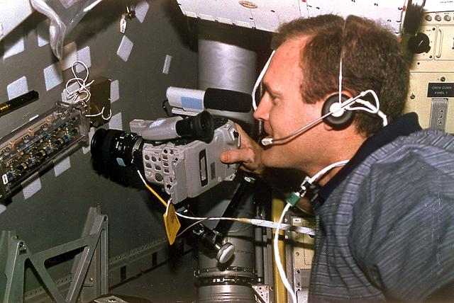
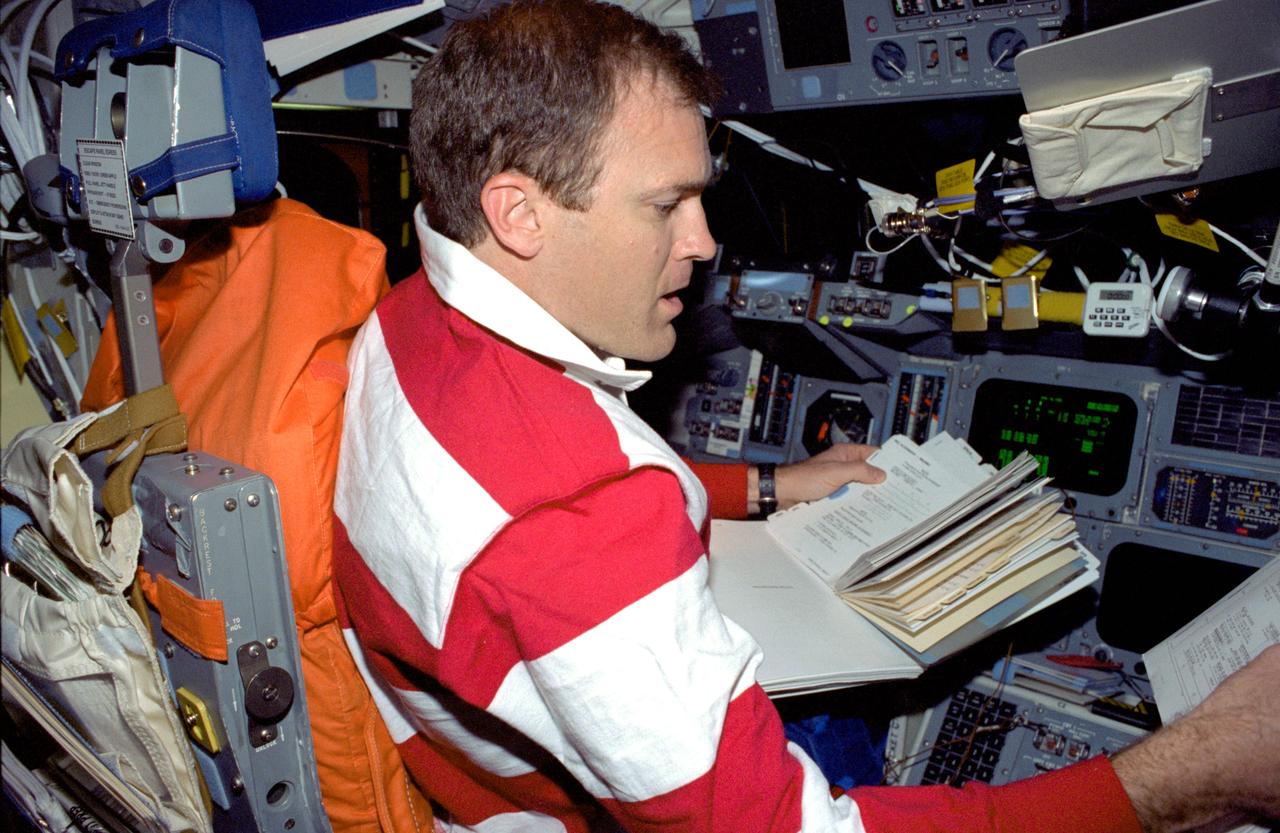
Astronaut James D. Halsell, Jr., mission commander, uses a Hi-8mm camcorder to videotape the Hand Held Diffusion Test Cells (HHDTC), in the Spacelab Science Module aboard the Earth-orbiting Space Shuttle Columbia (STS-94). Each test cell has three chambers containing a protein solution, a buffer solution and a precipitant solution chamber. Using the liquid-liquid diffusion method, the different fluids are brought into contact but not mixed. Over a period of time, the fluids will diffuse into each other through the random motion of molecules. The gradual increase in concentration of the precipitant within the protein solution causes the proteins to crystallize.
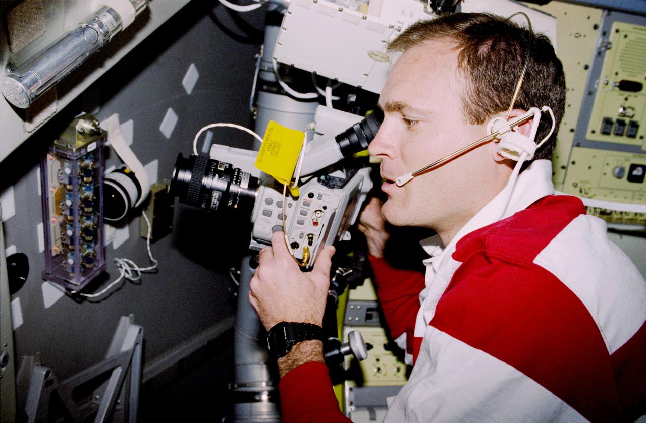
STS083-313-012 (4-8 April 1997) --- Astronaut James D. Halsell, Jr., mission commander, uses a Hi-8mm camcorder to videotape the Hand Held Diffusion Test Cells (HHDTC), in the Spacelab Module aboard the Earth-orbiting Space Shuttle Columbia. Each test cell has three chambers containing a protein solution, a buffer solution and a precipitant solution chamber. Using the liquid-liquid diffusion method, the different fluids are brought into contact but not mixed. Over a period of time, the fluids will diffuse into each other through the random motion of molecules. The gradual increase in concentration of the precipitant within the protein solution causes the proteins to crystallize.
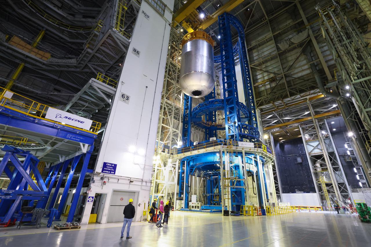
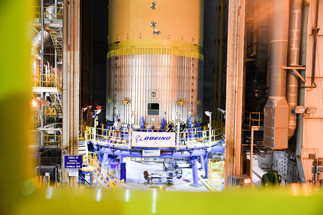
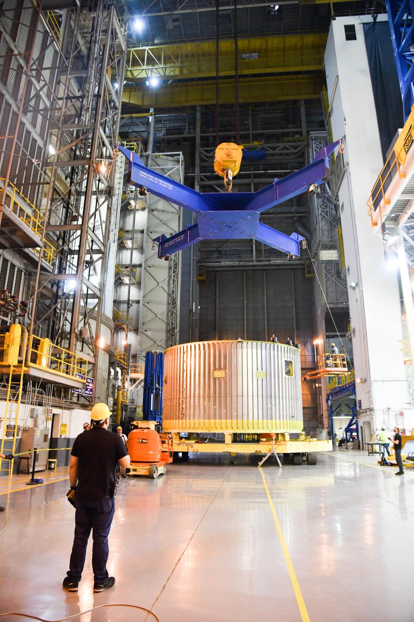
This image highlights the liquid hydrogen tank that will be used on the core stage of NASA’s Space Launch System rocket for Artemis II, the first crewed mission of NASA’s Artemis program. The tank is being built at NASA’s Michoud Assembly Facility in New Orleans. The SLS core stage is made up of five unique elements: the forward skirt, liquid oxygen tank, intertank, liquid hydrogen tank, and the engine section. The liquid hydrogen tank holds 537,000 gallons of liquid hydrogen cooled to minus 423 degrees Fahrenheit and sits between the core stage’s intertank and engine section. The liquid hydrogen hardware, along with the liquid oxygen tank, will provide propellant to the four RS-25 engines at the bottom of the cores stage to produce more than two million pounds of thrust to launch NASA’s Artemis missions to the Moon. Together with its four RS-25 engines, the rocket’s massive 212-foot-tall core stage — the largest stage NASA has ever built — and its twin solid rocket boosters will produce 8.8 million pounds of thrust to send NASA’s Orion spacecraft, astronauts and supplies beyond Earth’s orbit to the Moon and, ultimately, Mars. Offering more payload mass, volume capability and energy to speed missions through space, the SLS rocket, along with NASA’s Gateway in lunar orbit, the human landing system, and Orion spacecraft, is part of NASA’s backbone for deep space exploration and the Artemis lunar program. No other rocket can send astronauts in Orion around the Moon in a single mission.
This image highlights the liquid hydrogen tank that will be used on the core stage of NASA’s Space Launch System rocket for Artemis II, the first crewed mission of NASA’s Artemis program. The tank is being built at NASA’s Michoud Assembly Facility in New Orleans. The SLS core stage is made up of five unique elements: the forward skirt, liquid oxygen tank, intertank, liquid hydrogen tank, and the engine section. The liquid hydrogen tank holds 537,000 gallons of liquid hydrogen cooled to minus 423 degrees Fahrenheit and sits between the core stage’s intertank and engine section. The liquid hydrogen hardware, along with the liquid oxygen tank, will provide propellant to the four RS-25 engines at the bottom of the cores stage to produce more than two million pounds of thrust to launch NASA’s Artemis missions to the Moon. Together with its four RS-25 engines, the rocket’s massive 212-foot-tall core stage — the largest stage NASA has ever built — and its twin solid rocket boosters will produce 8.8 million pounds of thrust to send NASA’s Orion spacecraft, astronauts and supplies beyond Earth’s orbit to the Moon and, ultimately, Mars. Offering more payload mass, volume capability and energy to speed missions through space, the SLS rocket, along with NASA’s Gateway in lunar orbit, the human landing system, and Orion spacecraft, is part of NASA’s backbone for deep space exploration and the Artemis lunar program. No other rocket can send astronauts in Orion around the Moon in a single mission.
This image highlights the liquid hydrogen tank that will be used on the core stage of NASA’s Space Launch System rocket for Artemis II, the first crewed mission of NASA’s Artemis program. The tank is being built at NASA’s Michoud Assembly Facility in New Orleans. The SLS core stage is made up of five unique elements: the forward skirt, liquid oxygen tank, intertank, liquid hydrogen tank, and the engine section. The liquid hydrogen tank holds 537,000 gallons of liquid hydrogen cooled to minus 423 degrees Fahrenheit and sits between the core stage’s intertank and engine section. The liquid hydrogen hardware, along with the liquid oxygen tank, will provide propellant to the four RS-25 engines at the bottom of the cores stage to produce more than two million pounds of thrust to launch NASA’s Artemis missions to the Moon. Together with its four RS-25 engines, the rocket’s massive 212-foot-tall core stage — the largest stage NASA has ever built — and its twin solid rocket boosters will produce 8.8 million pounds of thrust to send NASA’s Orion spacecraft, astronauts and supplies beyond Earth’s orbit to the Moon and, ultimately, Mars. Offering more payload mass, volume capability and energy to speed missions through space, the SLS rocket, along with NASA’s Gateway in lunar orbit, the human landing system, and Orion spacecraft, is part of NASA’s backbone for deep space exploration and the Artemis lunar program. No other rocket can send astronauts in Orion around the Moon in a single mission.
This image highlights the liquid hydrogen tank that will be used on the core stage of NASA’s Space Launch System rocket for Artemis II, the first crewed mission of NASA’s Artemis program. The tank is being built at NASA’s Michoud Assembly Facility in New Orleans. The SLS core stage is made up of five unique elements: the forward skirt, liquid oxygen tank, intertank, liquid hydrogen tank, and the engine section. The liquid hydrogen tank holds 537,000 gallons of liquid hydrogen cooled to minus 423 degrees Fahrenheit and sits between the core stage’s intertank and engine section. The liquid hydrogen hardware, along with the liquid oxygen tank, will provide propellant to the four RS-25 engines at the bottom of the cores stage to produce more than two million pounds of thrust to launch NASA’s Artemis missions to the Moon. Together with its four RS-25 engines, the rocket’s massive 212-foot-tall core stage — the largest stage NASA has ever built — and its twin solid rocket boosters will produce 8.8 million pounds of thrust to send NASA’s Orion spacecraft, astronauts and supplies beyond Earth’s orbit to the Moon and, ultimately, Mars. Offering more payload mass, volume capability and energy to speed missions through space, the SLS rocket, along with NASA’s Gateway in lunar orbit, the human landing system, and Orion spacecraft, is part of NASA’s backbone for deep space exploration and the Artemis lunar program. No other rocket can send astronauts in Orion around the Moon in a single mission.
STS073-363-032 (20 October - 5 November 1995) --- Astronaut Kenneth D. Bowersox, STS-73 mission commander, studies the movement of fluids in microgravity at the Geophysical Fluid Flow Cell (GFFC) workstation in the science module of the Earth-orbiting Space Shuttle Columbia. Bowersox was joined by four other NASA astronauts and two guest researchers for almost 16-days of Earth-orbit research in support of the U.S. Microgravity Laboratory (USML-2) mission.
iss060e021175 (Aug. 2, 2019) --- Expedition 60 Flight Engineer Christina Koch of NASA activates the new BioFabrication Facility to test its ability to print cells. Researchers are exploring whether the weightless environment of space may support the fabrication of human organs in space. An incubator houses the tissue samples to promote cohesive cellular growth over several weeks. Earth’s gravity inhibits 3-D bioprinters and incubators from recreating and growing complex organic structures.
STS083-450-012 (4-8 April 1997) --- Astronaut James D. Halsell, Jr., commander, mans the commander's station aboard the Space Shuttle Columbia. Designed as a 16-day Microgravity Science Laboratory 1 (MSL-1) mission, the flight was cut short when one of three fuel cells did not function properly.
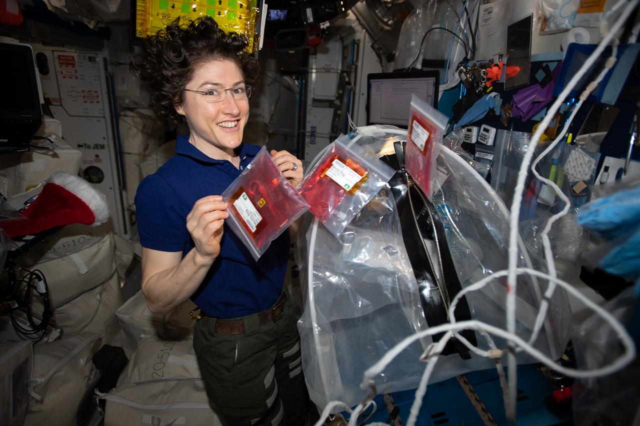
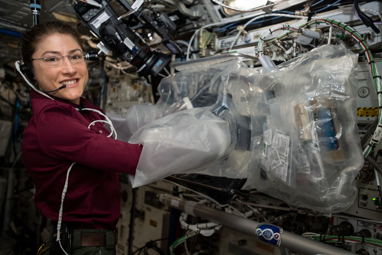
iss061e093848 (Dec. 22, 2019) --- Expedition 61 Flight Engineer and NASA astronaut Christina Koch handles media bags that enable the manufacturing of organ-like tissues using the the BioFabrication Facility (BFF), a 3-D biological printer. The BFF could become a part of a larger system capable of manufacturing whole, fully-functioning human organs from existing patient cells in microgravity.
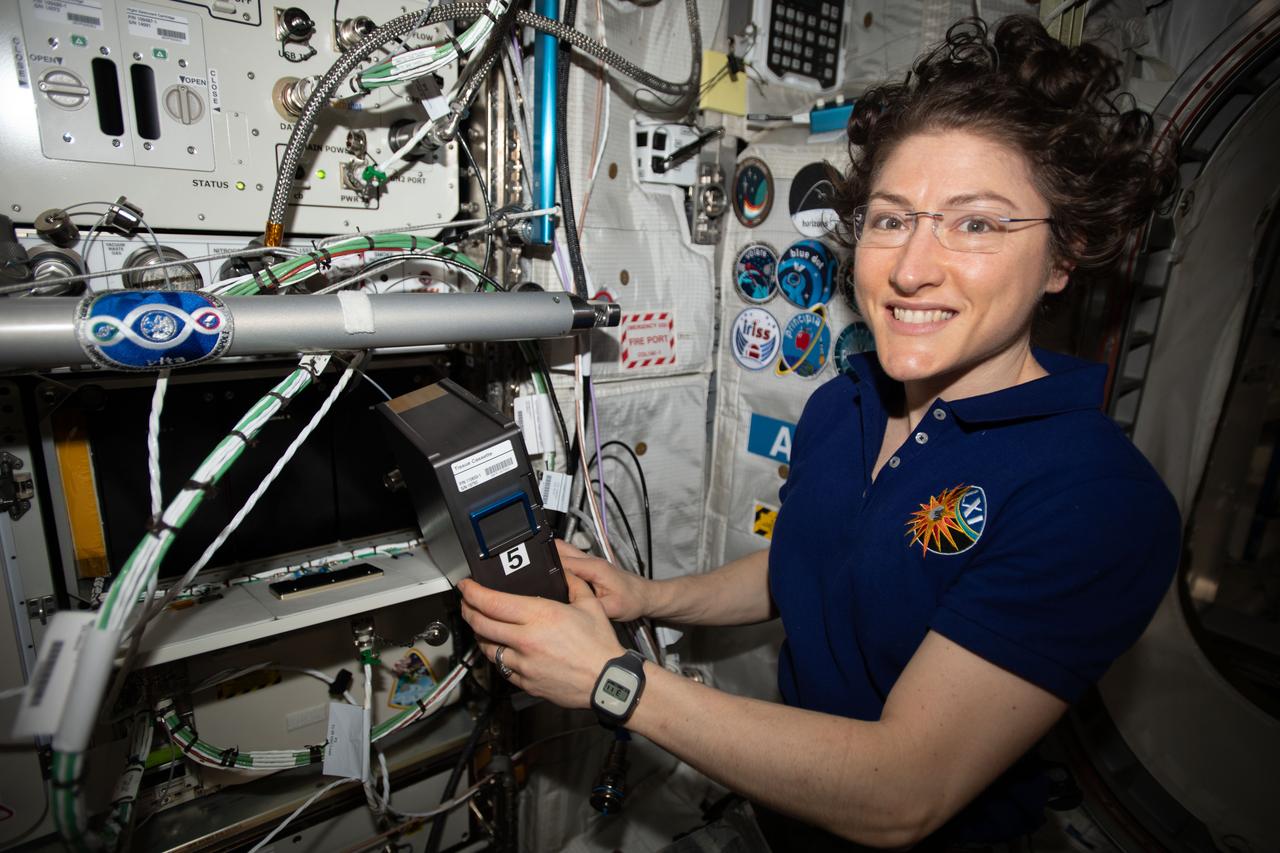
iss061e093837 (Dec. 22, 2019) --- Expedition 61 Flight Engineer and NASA astronaut Christina Koch services the BioFabrication Facility (BFF). The BFF is a 3-D biological printer that manufactures organ-like tissues in microgravity and could become a part of a larger system capable of manufacturing whole, fully-functioning human organs from existing patient cells.
S89-27383 (29 Dec 1988) --- This wide shot of a test cell in KSC's Vertical Processing Facility affords an overall scene of the mating process of the STS 29 tracking and data relay satellite (TDRS-D, in foreground) with its inertial upper stage (IUS-9, in lower part of frame). Later the tandem will be loaded into the cargo bay of Discovery.
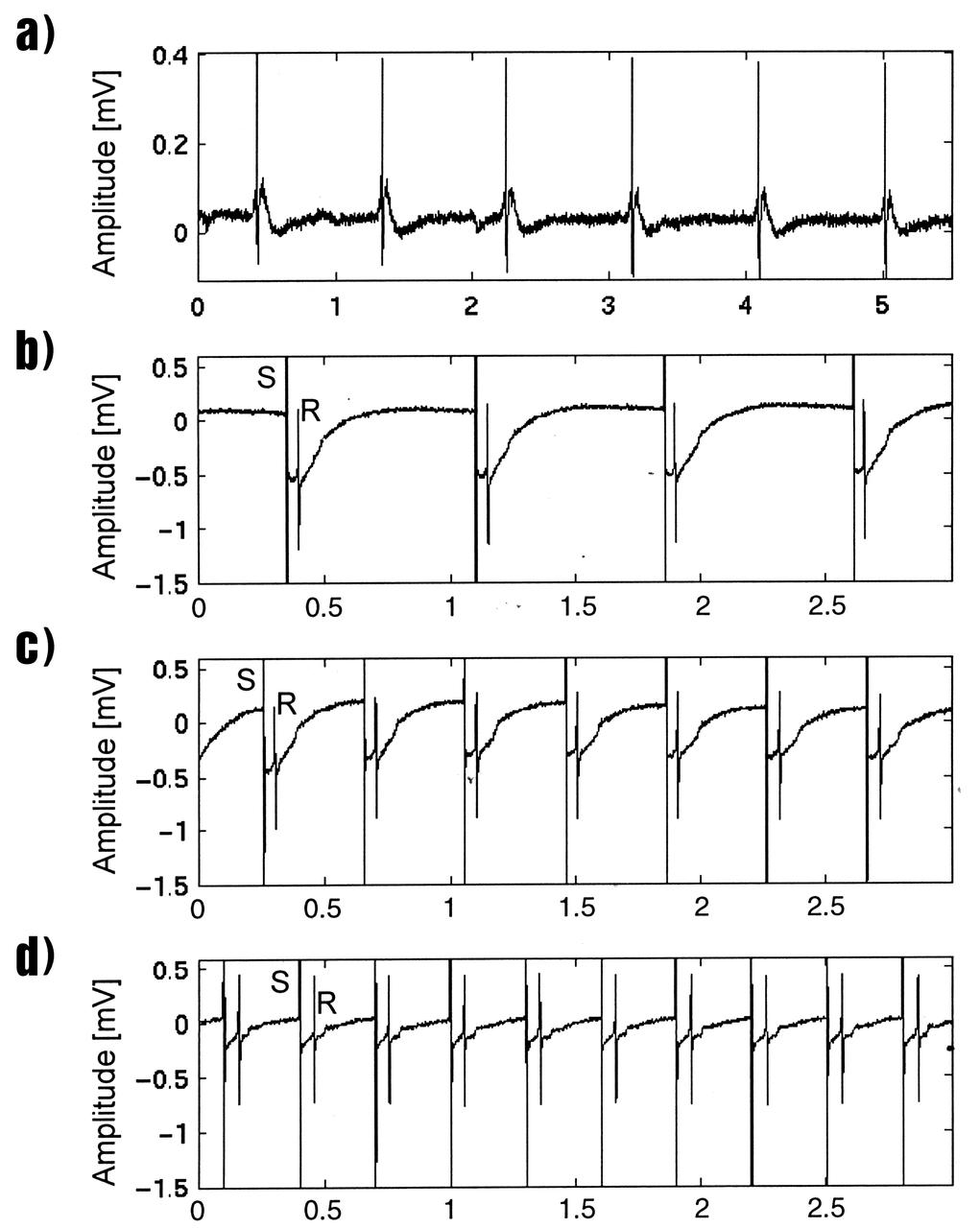
Lisa Freed and Gordana Vunjak-Novakovic, both of the Massachusetts Institute of Technology (MIT), have taken the first steps toward engineering heart muscle tissue that could one day be used to patch damaged human hearts. Cells isolated from very young animals are attached to a three-dimensional polymer scaffold, then placed in a NASA bioreactor. The cells do not divide, but after about a week start to cornect to form a functional piece of tissue. Functionally connected heart cells that are capable of transmitting electrical signals are the goal for Freed and Vunjak-Novakovic. Electrophysiological recordings of engineered tissue show spontaneous contractions at a rate of 70 beats per minute (a), and paced contractions at rates of 80, 150, and 200 beats per minute respectively (b, c, and d). The NASA Bioreactor provides a low turbulence culture environment which promotes the formation of large, three-dimensional cell clusters. The Bioreactor is rotated to provide gentle mixing of fresh and spent nutrient without inducing shear forces that would damage the cells. Due to their high level of cellular organization and specialization, samples constructed in the bioreactor more closely resemble the original tumor or tissue found in the body. NASA-sponsored bioreactor research has been instrumental in helping scientists to better understand normal and cancerous tissue development. In cooperation with the medical community, the bioreactor design is being used to prepare better models of human colon, prostate, breast and ovarian tumors. Cartilage, bone marrow, heart muscle, skeletal muscle, pancreatic islet cells, liver and kidney are just a few of the normal tissues being cultured in rotating bioreactors by investigators. The work is sponsored by NASA's Office of Biological and Physical Research. The bioreactor is managed by the Biotechnology Cell Science Program at NASA's Johnson Space Center (JSC). Credit: NASA and MIT.
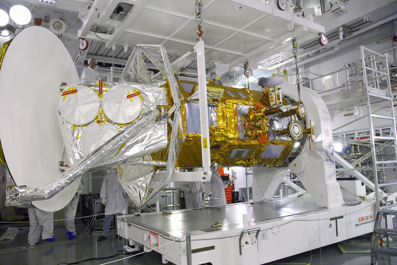
VANDENBERG AIR FORCE BASE, Calif. -- Technicians await the arrival of the Aquarius/SAC-D spacecraft to cell 3 at the Spaceport Systems International payload processing facility at Vandenberg Air Force Base in California. There, the spacecraft will undergo inspection of its solar arrays and tests will be conducted on its propulsion subsystem. Further testing of the satellites various other systems will follow. Following final tests, the spacecraft will be integrated to a United Launch Alliance Delta II rocket in preparation for the targeted June launch. Aquarius, the NASA-built primary instrument on the SAC-D spacecraft, will map global changes in salinity at the ocean's surface. The three-year mission will provide new insights into how variations in ocean surface salinity relate to these fundamental climate processes. Photo credit: NASA/Randy Beaudoin, VAFB
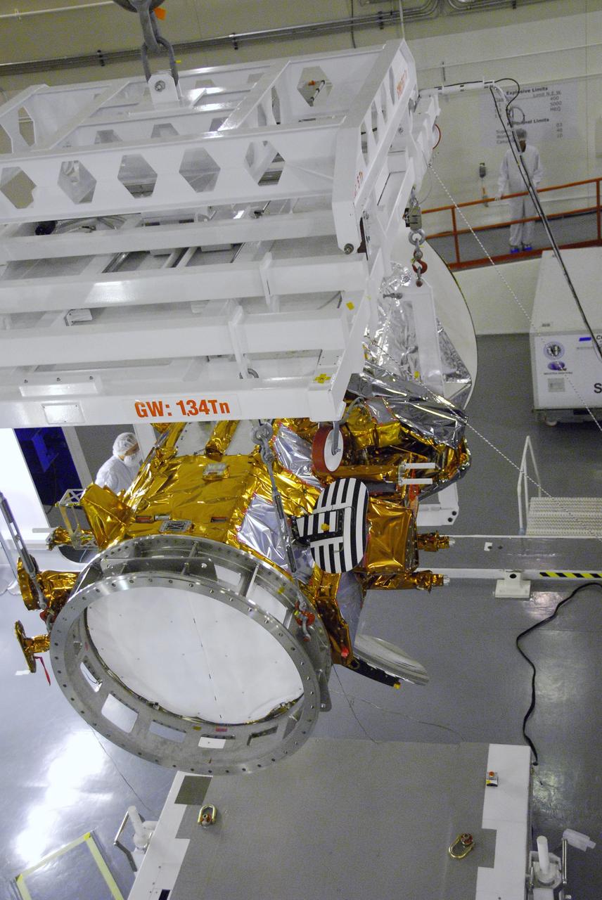
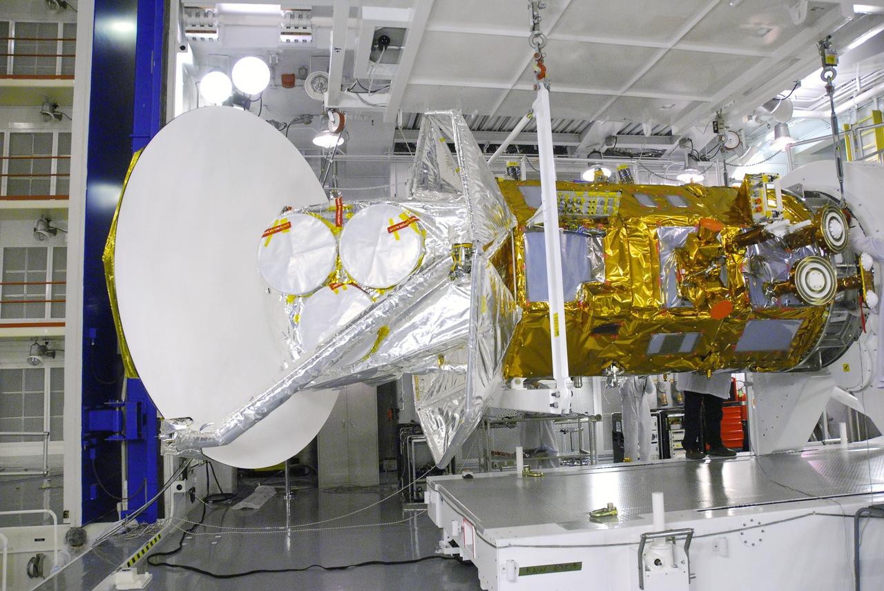
VANDENBERG AIR FORCE BASE, Calif. -- An overhead crane moves the Aquarius/SAC-D spacecraft to cell 3 at the Spaceport Systems International payload processing facility at Vandenberg Air Force Base in California. There, the spacecraft will undergo inspection of its solar arrays and tests will be conducted on its propulsion subsystem. Further testing of the satellites various other systems will follow. Following final tests, the spacecraft will be integrated to a United Launch Alliance Delta II rocket in preparation for the targeted June launch. Aquarius, the NASA-built primary instrument on the SAC-D spacecraft, will map global changes in salinity at the ocean's surface. The three-year mission will provide new insights into how variations in ocean surface salinity relate to these fundamental climate processes. Photo credit: NASA/Randy Beaudoin, VAFB
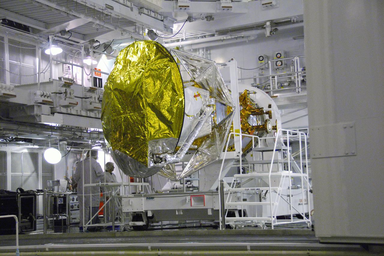
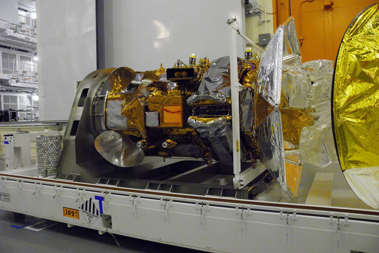
VANDENBERG AIR FORCE BASE, Calif. -- The Aquarius_SAC-D spacecraft is secured to the Rotation and Test Fixture in cell 3 at the Spaceport Systems International payload processing facility at Vandenberg Air Force Base in California. There, the spacecraft will undergo inspection of its solar arrays and tests will be conducted on its propulsion subsystem. Further testing of the satellites various other systems will follow. Following final tests, the spacecraft will be integrated to a United Launch Alliance Delta II rocket in preparation for the targeted June launch. Aquarius, the NASA-built primary instrument on the SAC-D spacecraft, will map global changes in salinity at the ocean's surface. The three-year mission will provide new insights into how variations in ocean surface salinity relate to these fundamental climate processes. Photo credit: NASA_Randy Beaudoin, VAFB
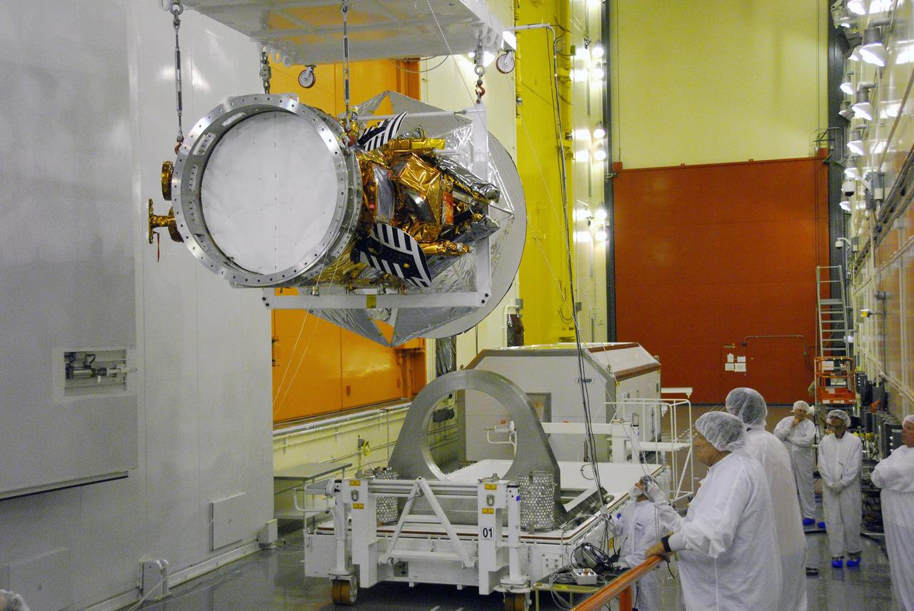
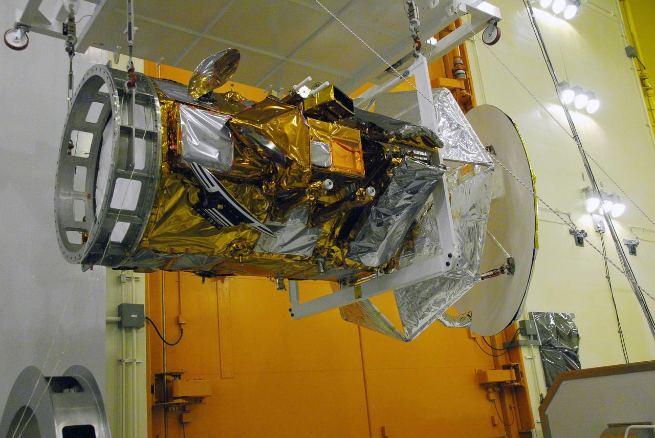
VANDENBERG AIR FORCE BASE, Calif. -- Technicians monitor the Aquarius/SAC-D spacecraft as it is being moved by an overhead crane from its stand to cell 3 at the Spaceport Systems International payload processing facility at Vandenberg Air Force Base in California. There, the spacecraft will undergo inspection of its solar arrays and tests will be conducted on its propulsion subsystem. Further testing of the satellites various other systems will follow. Following final tests, the spacecraft will be integrated to a United Launch Alliance Delta II rocket in preparation for the targeted June launch. Aquarius, the NASA-built primary instrument on the SAC-D spacecraft, will map global changes in salinity at the ocean's surface. The three-year mission will provide new insights into how variations in ocean surface salinity relate to these fundamental climate processes. Photo credit: NASA/Randy Beaudoin, VAFB
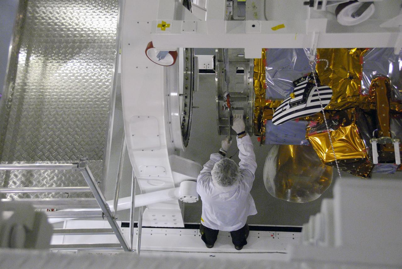
VANDENBERG AIR FORCE BASE, Calif. -- A technician guides the Aquarius/SAC-D spacecraft toward the Rotation and Test Fixture in cell 3 at the Spaceport Systems International payload processing facility at Vandenberg Air Force Base in California. There, the spacecraft will undergo inspection of its solar arrays and tests will be conducted on its propulsion subsystem. Further testing of the satellites various other systems will follow. Following final tests, the spacecraft will be integrated to a United Launch Alliance Delta II rocket in preparation for the targeted June launch. Aquarius, the NASA-built primary instrument on the SAC-D spacecraft, will map global changes in salinity at the ocean's surface. The three-year mission will provide new insights into how variations in ocean surface salinity relate to these fundamental climate processes. Photo credit: NASA/Randy Beaudoin, VAFB
VANDENBERG AIR FORCE BASE, Calif. -- Technicians monitor the Aquarius/SAC-D spacecraft as it is being moved by an overhead crane from its stand to cell 3 at the Spaceport Systems International payload processing facility at Vandenberg Air Force Base in California. There, the spacecraft will undergo inspection of its solar arrays and tests will be conducted on its propulsion subsystem. Further testing of the satellites various other systems will follow. Following final tests, the spacecraft will be integrated to a United Launch Alliance Delta II rocket in preparation for the targeted June launch. Aquarius, the NASA-built primary instrument on the SAC-D spacecraft, will map global changes in salinity at the ocean's surface. The three-year mission will provide new insights into how variations in ocean surface salinity relate to these fundamental climate processes. Photo credit: NASA/Randy Beaudoin, VAFB
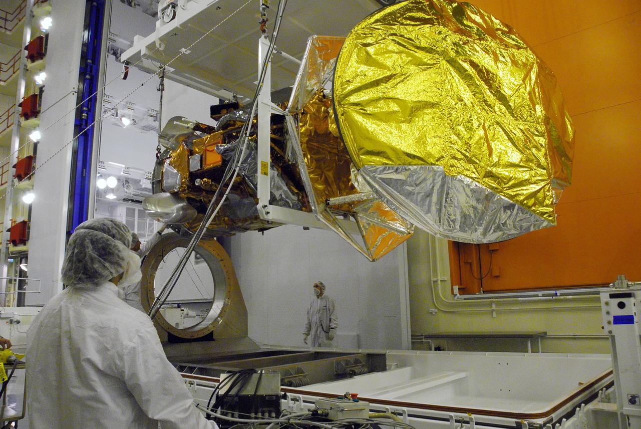
VANDENBERG AIR FORCE BASE, Calif. -- Technicians monitor the lifting of the Aquarius/SAC-D spacecraft from its stand by an overhead crane to cell 3 at the Spaceport Systems International payload processing facility at Vandenberg Air Force Base in California. There, the spacecraft will undergo inspection of its solar arrays and tests will be conducted on its propulsion subsystem. Further testing of the satellites various other systems will follow. Following final tests, the spacecraft will be integrated to a United Launch Alliance Delta II rocket in preparation for the targeted June launch. Aquarius, the NASA-built primary instrument on the SAC-D spacecraft, will map global changes in salinity at the ocean's surface. The three-year mission will provide new insights into how variations in ocean surface salinity relate to these fundamental climate processes. Photo credit: NASA/Randy Beaudoin, VAFB
VANDENBERG AIR FORCE BASE, Calif. -- The Aquarius/SAC-D spacecraft is secured to the Rotation and Test Fixture in cell 3 at the Spaceport Systems International payload processing facility at Vandenberg Air Force Base in California. There, the spacecraft will undergo inspection of its solar arrays and tests will be conducted on its propulsion subsystem. Further testing of the satellites various other systems will follow. Following final tests, the spacecraft will be integrated to a United Launch Alliance Delta II rocket in preparation for the targeted June launch. Aquarius, the NASA-built primary instrument on the SAC-D spacecraft, will map global changes in salinity at the ocean's surface. The three-year mission will provide new insights into how variations in ocean surface salinity relate to these fundamental climate processes. Photo credit: NASA/Randy Beaudoin, VAFB
VANDENBERG AIR FORCE BASE, Calif. -- A technician secures the Aquarius/SAC-D spacecraft to the Rotation and Test Fixture in cell 3 at the Spaceport Systems International payload processing facility at Vandenberg Air Force Base in California. There, the spacecraft will undergo inspection of its solar arrays and tests will be conducted on its propulsion subsystem. Further testing of the satellites various other systems will follow. Following final tests, the spacecraft will be integrated to a United Launch Alliance Delta II rocket in preparation for the targeted June launch. Aquarius, the NASA-built primary instrument on the SAC-D spacecraft, will map global changes in salinity at the ocean's surface. The three-year mission will provide new insights into how variations in ocean surface salinity relate to these fundamental climate processes. Photo credit: NASA/Randy Beaudoin, VAFB
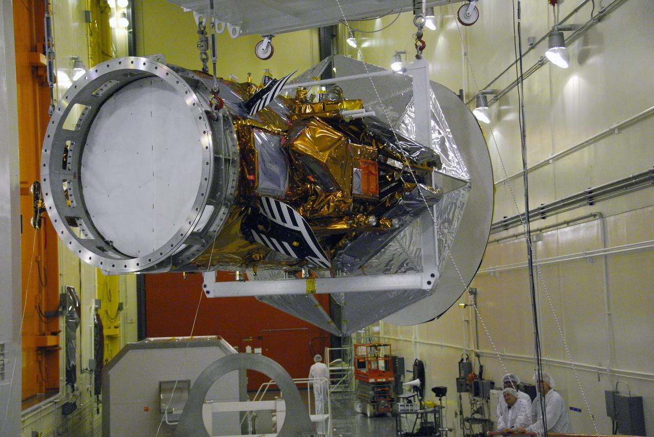
VANDENBERG AIR FORCE BASE, Calif. -- The Aquarius/SAC-D spacecraft is being prepared for its move to cell 3 at the Spaceport Systems International payload processing facility at Vandenberg Air Force Base in California. There, the spacecraft will undergo inspection of its solar arrays and tests will be conducted on its propulsion subsystem. Further testing of the satellites various other systems will follow. Following final tests, the spacecraft will be integrated to a United Launch Alliance Delta II rocket in preparation for the targeted June launch. Aquarius, the NASA-built primary instrument on the SAC-D spacecraft, will map global changes in salinity at the ocean's surface. The three-year mission will provide new insights into how variations in ocean surface salinity relate to these fundamental climate processes. Photo credit: NASA/Randy Beaudoin, VAFB
VANDENBERG AIR FORCE BASE, Calif. -- An overhead crane lifts the Aquarius/SAC-D spacecraft from its stand by an overhead to cell 3 at the Spaceport Systems International payload processing facility at Vandenberg Air Force Base in California. There, the spacecraft will undergo inspection of its solar arrays and tests will be conducted on its propulsion subsystem. Further testing of the satellites various other systems will follow. Following final tests, the spacecraft will be integrated to a United Launch Alliance Delta II rocket in preparation for the targeted June launch. Aquarius, the NASA-built primary instrument on the SAC-D spacecraft, will map global changes in salinity at the ocean's surface. The three-year mission will provide new insights into how variations in ocean surface salinity relate to these fundamental climate processes. Photo credit: NASA/Randy Beaudoin, VAFB
VANDENBERG AIR FORCE BASE, Calif. -- Technicians prepare the Aquarius/SAC-D spacecraft for its move to cell 3 at the Spaceport Systems International payload processing facility at Vandenberg Air Force Base in California. There, the spacecraft will undergo inspection of its solar arrays and tests will be conducted on its propulsion subsystem. Further testing of the satellites various other systems will follow. Following final tests, the spacecraft will be integrated to a United Launch Alliance Delta II rocket in preparation for the targeted June launch. Aquarius, the NASA-built primary instrument on the SAC-D spacecraft, will map global changes in salinity at the ocean's surface. The three-year mission will provide new insights into how variations in ocean surface salinity relate to these fundamental climate processes. Photo credit: NASA/Randy Beaudoin, VAFB
VANDENBERG AIR FORCE BASE, Calif. -- With the aid of an overhead crane, technicians guide the Aquarius/SAC-D spacecraft from its stand to cell 3 at the Spaceport Systems International payload processing facility at Vandenberg Air Force Base in California. There, the spacecraft will undergo inspection of its solar arrays and tests will be conducted on its propulsion subsystem. Further testing of the satellites various other systems will follow. Following final tests, the spacecraft will be integrated to a United Launch Alliance Delta II rocket in preparation for the targeted June launch. Aquarius, the NASA-built primary instrument on the SAC-D spacecraft, will map global changes in salinity at the ocean's surface. The three-year mission will provide new insights into how variations in ocean surface salinity relate to these fundamental climate processes. Photo credit: NASA/Randy Beaudoin, VAFB

Lisa Freed and Gordana Vunjak-Novakovic, both of the Massachusetts Institute of Technology (MIT), have taken the first steps toward engineering heart muscle tissue that could one day be used to patch damaged human hearts. Cells isolated from very young animals are attached to a three-dimensional polymer scaffold, then placed in a NASA bioreactor. The cells do not divide, but after about a week start to cornect to form a functional piece of tissue. Here, a transmission electron micrograph of engineered tissue shows a number of important landmarks present in functional heart tissue: (A) well-organized myofilaments (Mfl), z-lines (Z), and abundant glycogen granules (Gly); and (D) intercalcated disc (ID) and desmosomes (DES). The NASA Bioreactor provides a low turbulence culture environment which promotes the formation of large, three-dimensional cell clusters. The Bioreactor is rotated to provide gentle mixing of fresh and spent nutrient without inducing shear forces that would damage the cells. Due to their high level of cellular organization and specialization, samples constructed in the bioreactor more closely resemble the original tumor or tissue found in the body. NASA-sponsored bioreactor research has been instrumental in helping scientists to better understand normal and cancerous tissue development. In cooperation with the medical community, the bioreactor design is being used to prepare better models of human colon, prostate, breast and ovarian tumors. Cartilage, bone marrow, heart muscle, skeletal muscle, pancreatic islet cells, liver and kidney are just a few of the normal tissues being cultured in rotating bioreactors by investigators. The work is sponsored by NASA's Office of Biological and Physical Research. The bioreactor is managed by the Biotechnology Cell Science Program at NASA's Johnson Space Center (JSC). Credit: MIT
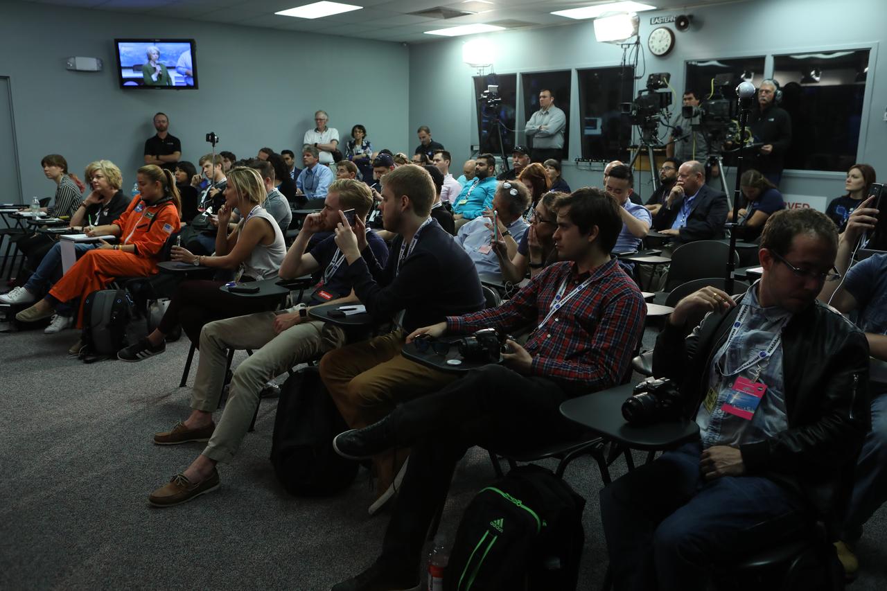
NASA Social participants attend a "What's on Board" science, research and technology briefing at NASA's Kennedy Space Center in Florida, for Orbital ATK's seventh commercial resupply services mission, CRS-7, to the International Space Station. Participants discussed some of the science launching to the space station, including the Advanced Plant Habitat, 3-D cell tools, and CubeSats set to deploy from space. Orbital ATK's Cygnus pressurized cargo module is set to launch on the United Launch Alliance Atlas V rocket from Space Launch Complex 41 at Cape Canaveral Air Force Station on April 18. Liftoff is scheduled for 11:11 a.m. EDT.
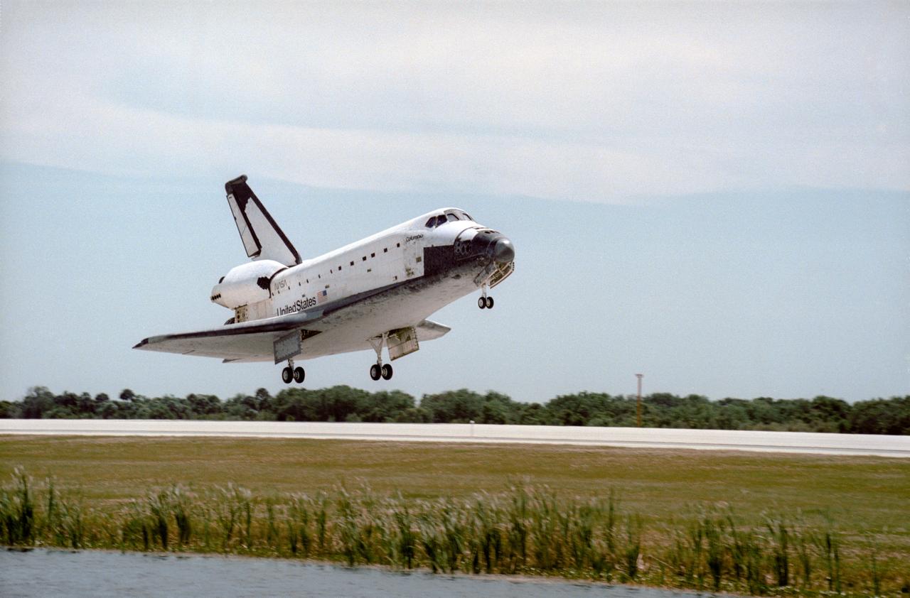
STS083-S-009 (8 April 1997) --- The Space Shuttle Columbia nears touchdown on the Shuttle Landing Facility (SLF) runway at the Kennedy Space Center (KSC), after completing almost four days of a scheduled 16-day mission in Earth-orbit. A problem with one of three fuel cells led to an early landing for the seven-member Microgravity Science Laboratory 1 (MSL-1) crew. Touchdown occurred at 1:33:11 p.m. (EDT), April 8, 1997. Onboard Columbia were James D. Halsell, Jr., Susan L. Still, Janice E. Voss, Donald A. Thomas, Michael L. Gernhardt, Roger K. Crouch and Gregory T. Linteris.

STS-94 Commander James D. Halsell, Jr., arrives at the Shuttle Landing Facility aboard a T-38 jet in preparation for the reflight of the Microgravity Science Laboratory-1 mission. Launch is scheduled for July 1, 1997, at 2:37 p.m. EDT. The laboratory was scheduled to fly again with the full complement of STS-83 experiments after that mission was cut short due to a faulty fuel cell. During the scheduled 16-day STS-94 mission, the experiments will be used to test some of the hardware, facilities and procedures that are planned for use on the International Space Station while the flight crew conducts combustion, protein crystal growth and materials processing experiments
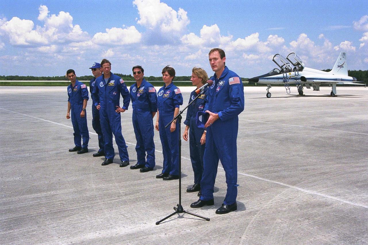
STS-94 Commander James D. Halsell, Jr., speaks to the media at the Shuttle Landing Facility after the crew arrived at Kennedy Space Center in preparation for the reflight of the Microgravity Science Laboratory-1 mission. Launch is scheduled for July 1, 1997, at 2:37 p.m. EDT. From left to right, the crew members are Payload Specialists Gregory T. Linteris and Roger K. Crouch; Mission Specialists Michael L. Gernhardt and Donald A. Thomas; Payload Commander Janice E. Voss; Pilot Susan Leigh Still and Commander James D. Halsell, Jr. One of the T-38 jets aboard which the crew arrived can be seen in the background. The laboratory was scheduled to fly again with the full complement of STS-83 experiments after that mission was cut short due to a faulty fuel cell. During the scheduled 16-day STS-94 mission, the experiments will be used to test some of the hardware, facilities and procedures that are planned for use on the International Space Station while the flight crew conducts combustion, protein crystal growth and materials processing experiments
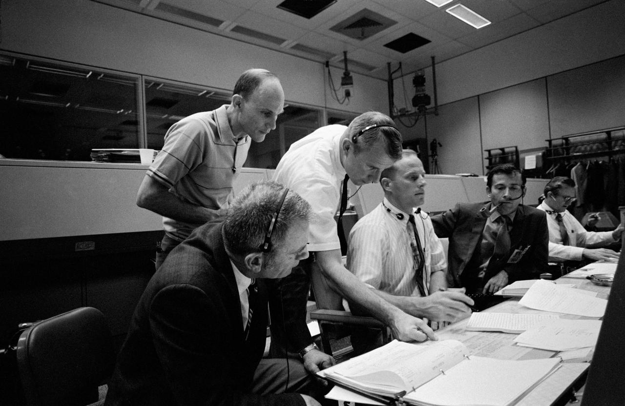
S70-34902 (14 April 1970) --- Several persons important to the Apollo 13 mission, at consoles in the Mission Operations Control Room (MOCR) of the Mission Control Center (MCC). Seated at consoles, from left to right, are astronauts Donald K. Slayton, director of flight crew operations; astronaut Jack R. Lousma, Shift 3 spacecraft communicator; and astronaut John W. Young, commander of the Apollo 13 backup crew. Standing, left to right, are astronaut Tom K. Mattingly II, who was replaced as Apollo 13 command module pilot after it was learned he may come down with measles, and astronaut Vance D. Brand, Shift 2 spacecraft communicator. Several hours earlier, in the late evening hours of April 13, crew members of the Apollo 13 mission reported to MCC that trouble had developed with an oxygen cell on their spacecraft.

At Launch Pad 39A, orbiter Endeavour's open payload bay doors, reflecting the surrounding light, reveal the payload on the Shuttle Radar Topography Mission, STS-99. The mission will chart a new course, using two antennae and a 200-foot-long section of space station-derived mast protruding from the payload bay to produce unrivaled 3-D images of the Earth's surface. The result of the Shuttle Radar Topography Mission could be close to 1 trillion measurements of the Earth's topography. Besides contributing to the production of better maps, these measurements could lead to improved water drainage modeling, more realistic flight simulators, better locations for cell phone towers, and enhanced navigation safety. Launch of Endeavour on the 11-day mission is scheduled for Jan. 31 at 12:47 p.m. EST
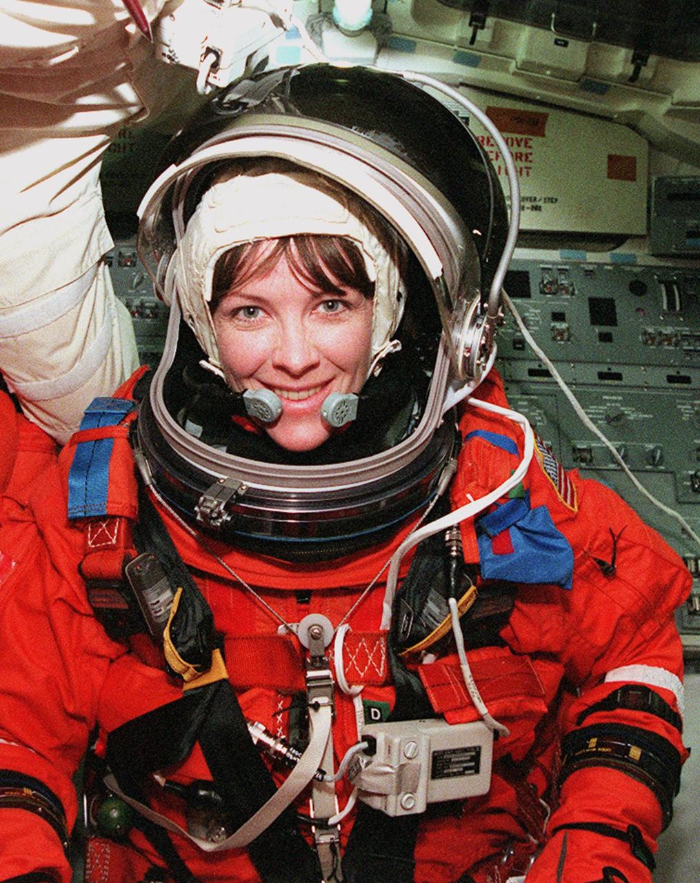
STS-99 Mission Specialist Janet Lynn Kavandi (Ph.D.) settles into her seat inside Space Shuttle Endeavour during Terminal Countdown Demonstration Test (TCDT) activities for the mission. The TCDT includes a simulation of the final launch countdown. STS-99 is the Shuttle Radar Topography Mission, which will chart a new course, using two antennae and a 200-foot-long section of space station-derived mast protruding from the payload bay to produce unrivaled 3-D images of the Earth's surface. The result of the Shuttle Radar Topography Mission could be close to 1 trillion measurements of the Earth's topography. Besides contributing to the production of better maps, these measurements could lead to improved water drainage modeling, more realistic flight simulators, better locations for cell phone towers, and enhanced navigation safety. Launch of Endeavour on the 11-day mission is scheduled for Jan. 31 at 12:47 p.m. EST
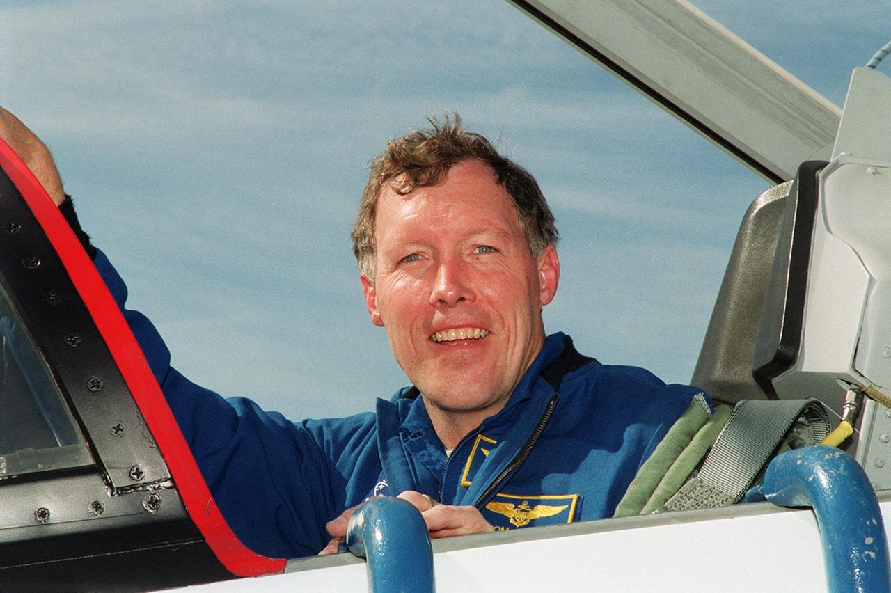
STS-99 Pilot Dominic Gorie arrives at KSC aboard a T-38 jet aircraft to prepare for launch of Endeavour Jan. 31 at 12:47 p.m. EST. Over the next few days, the crew will review mission procedures, conduct test flights in the Shuttle Training Aircraft and undergo routine preflight medical exams. STS-99 is the Shuttle Radar Topography Mission, which will chart a new course, using two antennae and a 200-foot-long section of space station-derived mast protruding from the payload bay to produce unrivaled 3-D images of the Earth's surface. The result of the Shuttle Radar Topography Mission could be close to 1 trillion measurements of the Earth's topography. Besides contributing to the production of better maps, these measurements could lead to improved water drainage modeling, more realistic flight simulators, better locations for cell phone towers, and enhanced navigation safety
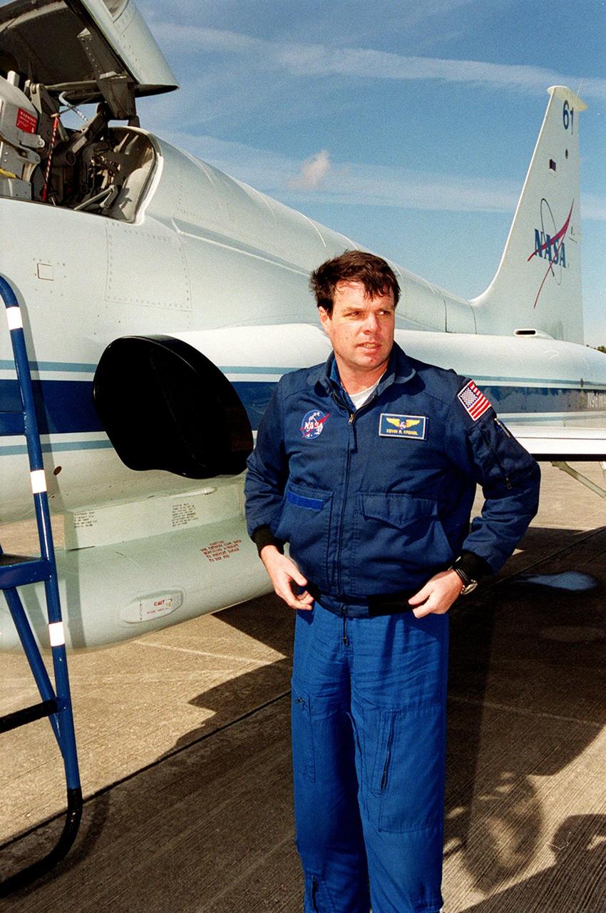
STS-99 Commander Kevin Kregel arrives at KSC aboard a T-38 jet aircraft to prepare for launch of Endeavour Jan. 31 at 12:47 p.m. EST. Over the next few days, the crew will review mission procedures, conduct test flights in the Shuttle Training Aircraft and undergo routine preflight medical exams. STS-99 is the Shuttle Radar Topography Mission, which will chart a new course, using two antennae and a 200-foot-long section of space station-derived mast protruding from the payload bay to produce unrivaled 3-D images of the Earth's surface. The result of the Shuttle Radar Topography Mission could be close to 1 trillion measurements of the Earth's topography. Besides contributing to the production of better maps, these measurements could lead to improved water drainage modeling, more realistic flight simulators, better locations for cell phone towers, and enhanced navigation safety
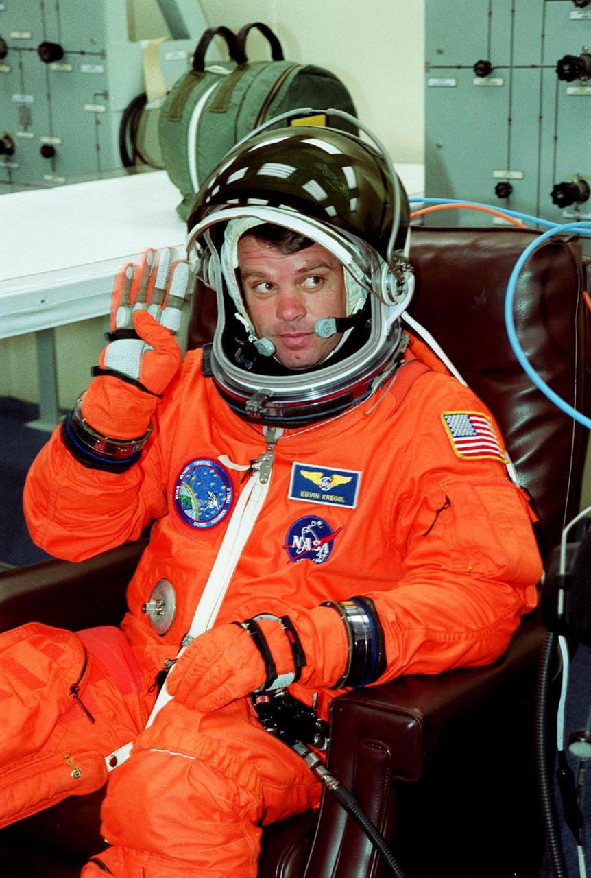
In the Operations and Checkout Building, STS-99 Commander Kevin Kregel waves as he suits up during final launch preparations. Liftoff of STS-99, known as the Shuttle Radar Topography Mission (SRTM), is scheduled for 12:47 p.m. EST from Launch Pad 39A. The SRTM will chart a new course to produce unrivaled 3-D images of the Earth's surface, using two antennae and a 200-foot-long section of space station-derived mast protruding from the payload bay. The result of the Shuttle Radar Topography Mission could be close to 1 trillion measurements of the Earth's topography. Besides contributing to the production of better maps, these measurements could lead to improved water drainage modeling, more realistic flight simulators, better locations for cell phone towers, and enhanced navigation safety. The mission is expected to last about 11days. Endeavour is expected to land at KSC Friday, Feb. 11, at 4:55 p.m. EST
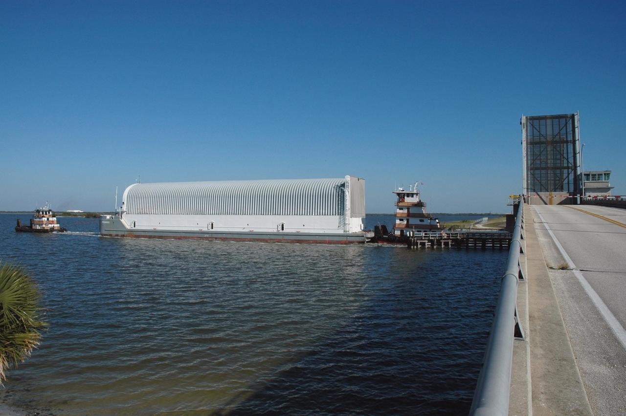
KENNEDY SPACE CENTER, FLA. - The Pegasus barge passes under the Roy D. Bridges Bridge in the Banana River, as it nears the end of its journey from the Michoud Assembly Facility in New Orleans to Kennedy Space Center. The barge carries the redesigned external fuel tank that will launch Space Shuttle Discovery on the next shuttle mission, STS-121. After off-loading, the tank will be moved into the Vehicle Assembly Building and lifted into a checkout cell for further work. The tank, designated ET-119, will fly with many major safety changes, including the removal of the protuberance air load ramps. A large piece of foam from a ramp came off during the last shuttle launch in July 2005. The ramps were removed to eliminate a potential source of damaging debris to the space shuttle. The next launch of Discovery is scheduled for May 2006.

At Launch Pad 39A, orbiter Endeavour's open payload bay doors reveal the payload on the Shuttle Radar Topography Mission, STS-99. The mission will chart a new course, using two antennae and a 200-foot-long section of space station-derived mast protruding from the payload bay to produce unrivaled 3-D images of the Earth's surface. The result of the Shuttle Radar Topography Mission could be close to 1 trillion measurements of the Earth's topography. Besides contributing to the production of better maps, these measurements could lead to improved water drainage modeling, more realistic flight simulators, better locations for cell phone towers, and enhanced navigation safety. Launch of Endeavour on the 11-day mission is scheduled for Jan. 31 at 12:47 p.m. EST
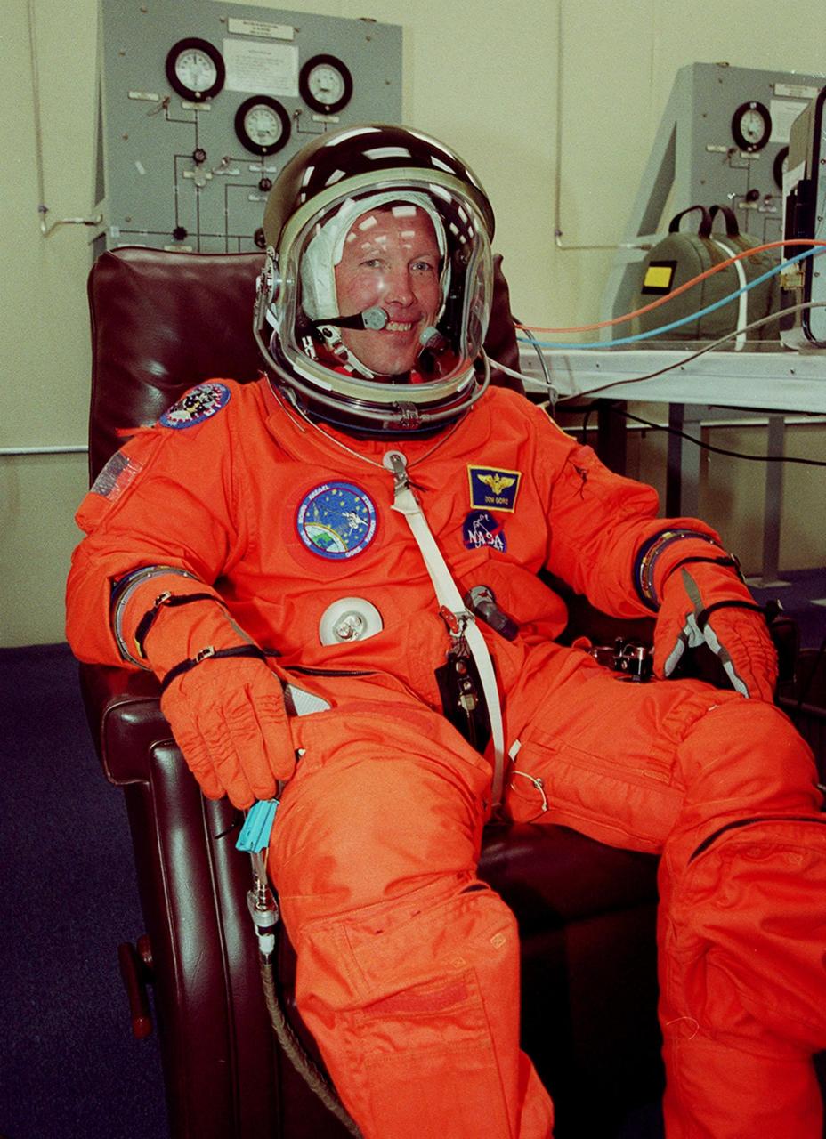
In the Operations and Checkout Building, STS-99 Pilot Dominic Gorie smiles during suitup in final launch preparations. Liftoff of STS-99, known as the Shuttle Radar Topography Mission, is scheduled for 12:47 p.m. EST from Launch Pad 39A. The SRTM will chart a new course to produce unrivaled 3-D images of the Earth's surface, using two antennae and a 200-foot-long section of space station-derived mast protruding from the payload bay. The result of the Shuttle Radar Topography Mission could be close to 1 trillion measurements of the Earth's topography. Besides contributing to the production of better maps, these measurements could lead to improved water drainage modeling, more realistic flight simulators, better locations for cell phone towers, and enhanced navigation safety. The mission is expected to last about 11days, with Endeavour landing at KSC Friday, Feb. 11, at 4:55 p.m. EST