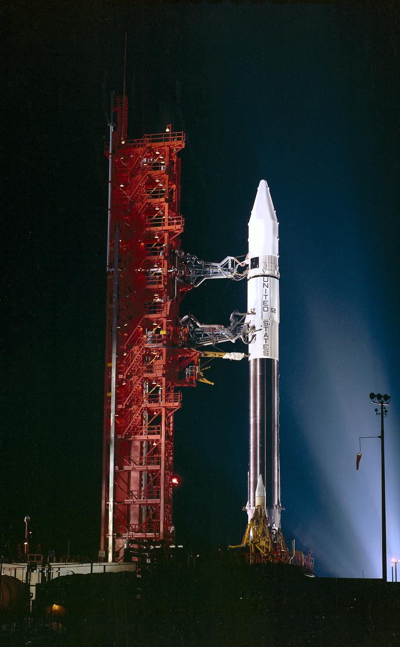
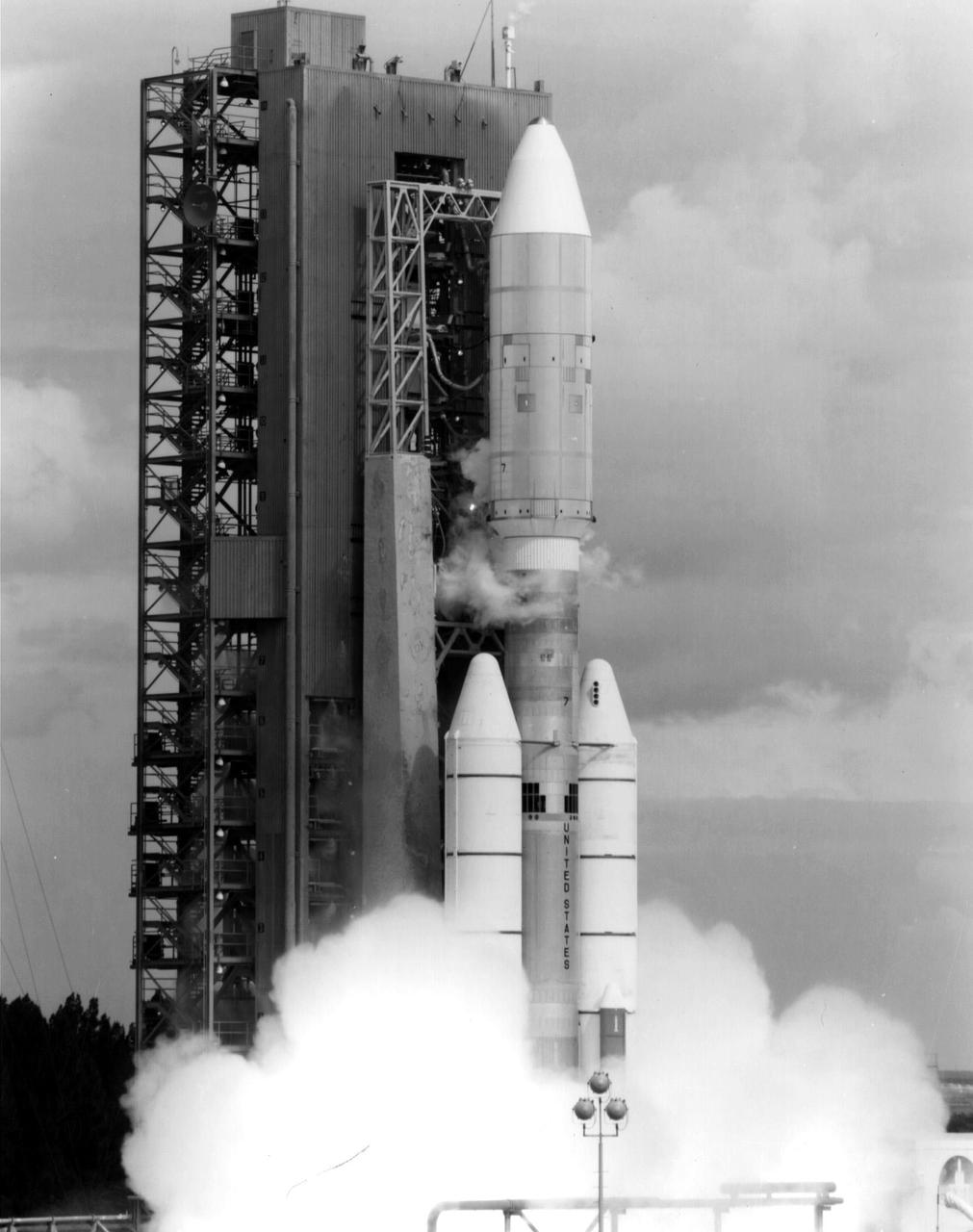
The Atlas-Centaur-52 launch vehicle on the launch pad. The Atlas-Centaur-52 placed the High Energy Astronomy Observatory-2 (HEAO-2) in orbit on November 13, 1978.
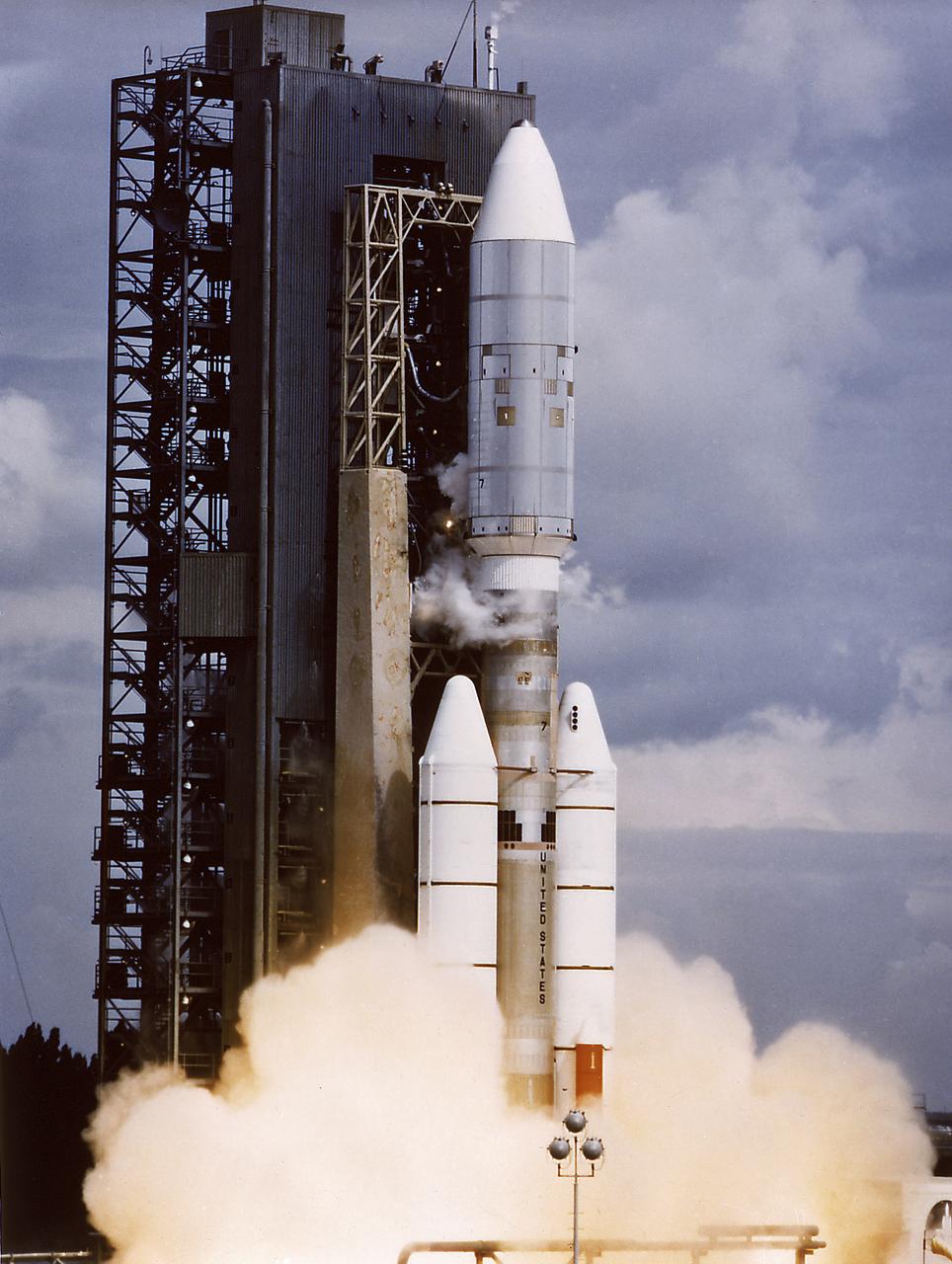
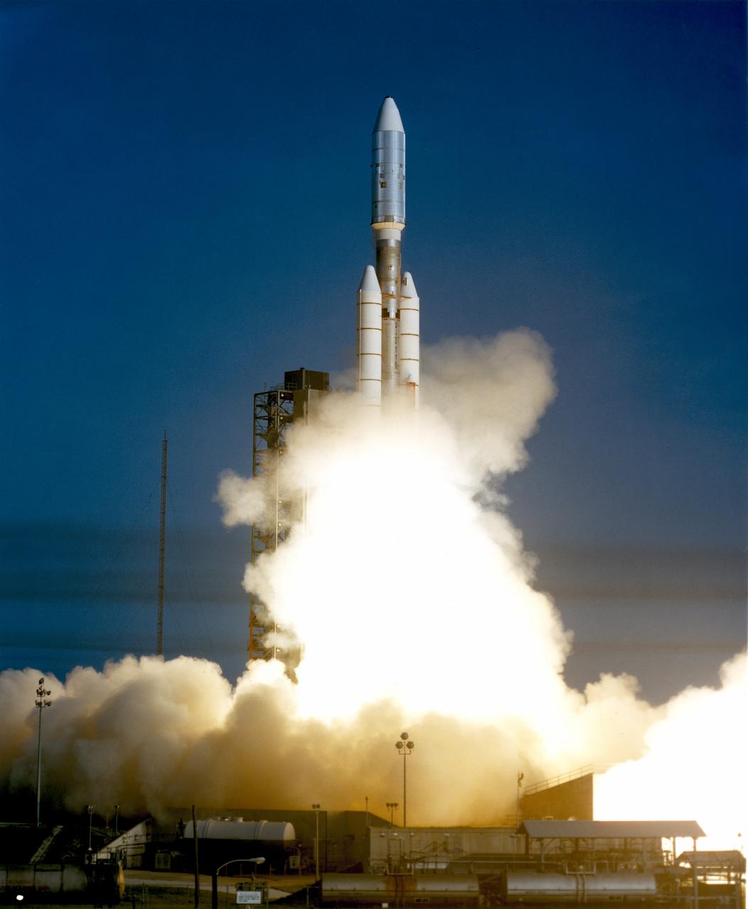
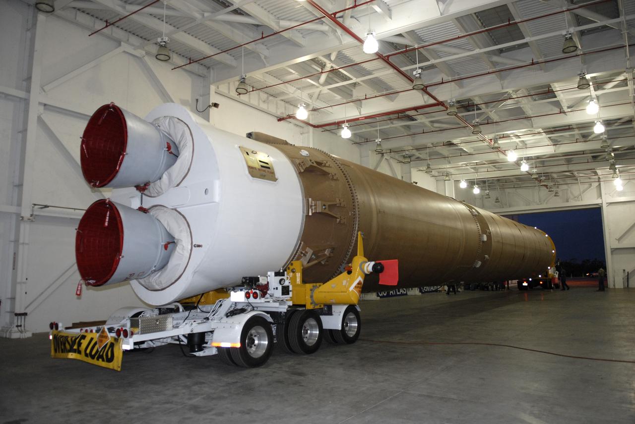
The Voyager 2 aboard Titan III-Centaur launch vehicle lifted off on August 20, 1977. The Voyager 2 was a scientific satellite to study the Jupiter and the Saturn planetary systems including their satellites and Saturn's rings.

The launch of an Atlas/Centaur launch vehicle is shown in this photograph. The Atlas/Centaur, launched on November 13, 1978, carried the High Energy Astronomy Observatory (HEAO)-2 into the required orbit. The second observatory, the HEAO-2 (nicknamed the Einstein Observatory in honor of the centernial of the birth of Albert Einstein) carried the first telescope capable of producing actual photographs of x-ray objects.
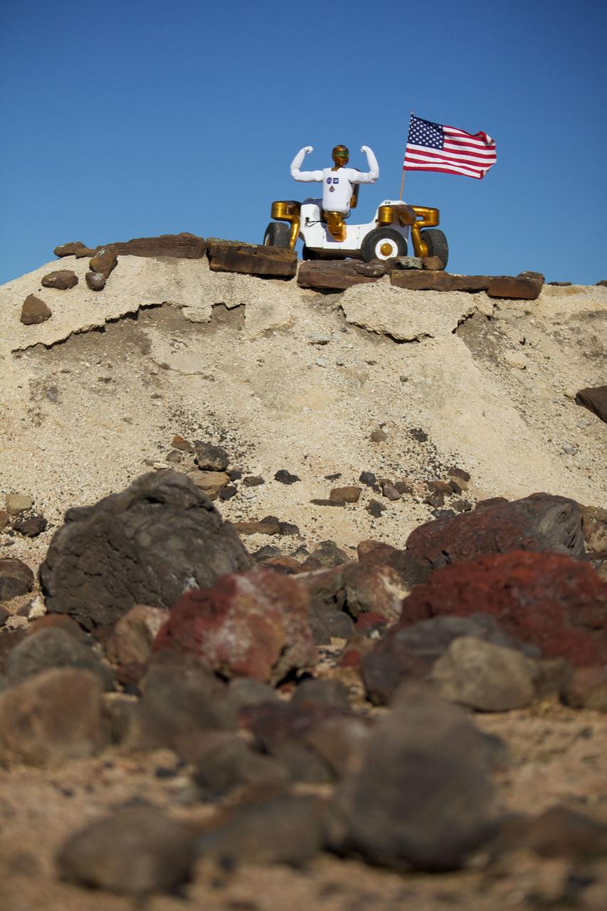
JSC2011-E-017946 (February 2011) --- Robonaut 2 poses atop its new wheeled base, Centaur 2, at the Johnson Space Center Planetary Analog Test Site. The Centaur base builds off of lessons learned through the Space Exploration Vehicle, a rover for astronauts, and could allow the dexterous humanoid robot to help with the future exploration of distant planetary surfaces. Photo credit: NASA or National Aeronautics and Space Administration

JSC2011-E-017945 (February 2011) --- Robonaut 2 poses atop its new wheeled base, Centaur 2, at the Johnson Space Center Planetary Analog Test Site. The Centaur base builds off of lessons learned through the Space Exploration Vehicle, a rover for astronauts, and could allow the dexterous humanoid robot to help with the future exploration of distant planetary surfaces. Photo credit: NASA or National Aeronautics and Space Administration
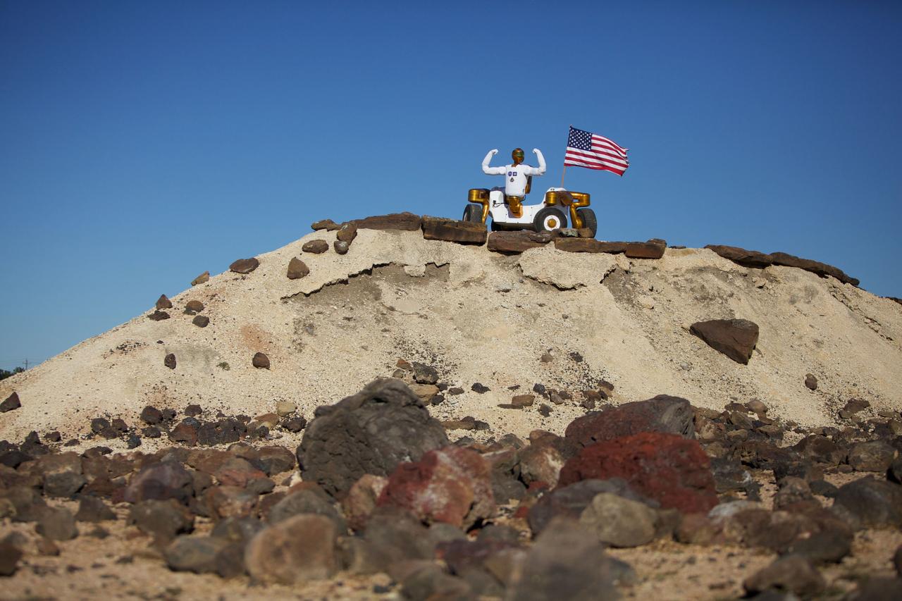
JSC2011-E-017947 (February 2011) --- Robonaut 2 poses atop its new wheeled base, Centaur 2, at the Johnson Space Center Planetary Analog Test Site. The Centaur base builds off of lessons learned through the Space Exploration Vehicle, a rover for astronauts, and could allow the dexterous humanoid robot to help with the future exploration of distant planetary surfaces. Photo credit: NASA or National Aeronautics and Space Administration
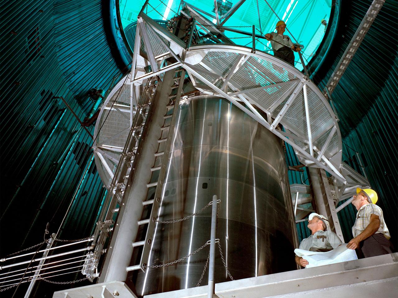
A Centaur second-stage rocket in the Space Propulsion Research Facility, better known as B‒2, operating at NASA’s Plum Brook Station in Sandusky, Ohio. Centaur was designed to be used with an Atlas booster to send the Surveyor spacecraft to the moon in the mid-1960s. After those missions, the rocket was modified to launch a series of astronomical observation satellites into orbit and send space probes to other planets. Researchers conducted a series of systems tests at the Plum Brook test stands to improve the Centaur fuel pumping system. Follow up full-scale tests in the B-2 facility led to the eventual removal of the boost pumps from the design. This reduced the system’s complexity and significantly reduced the cost of a Centaur rocket. The Centaur tests were the first use of the new B-2 facility. B‒2 was the world's only high altitude test facility capable of full-scale rocket engine and launch vehicle system level tests. It was created to test rocket propulsion systems with up to 100,000 pounds of thrust in a simulated space environment. The facility has the unique ability to maintain a vacuum at the rocket’s nozzle while the engine is firing. The rocket fires into a 120-foot deep spray chamber which cools the exhaust before it is ejected outside the facility. B‒2 simulated space using giant diffusion pumps to reduce chamber pressure 10-6 torr, nitrogen-filled cold walls create cryogenic temperatures, and quartz lamps replicate the radiation of the sun.
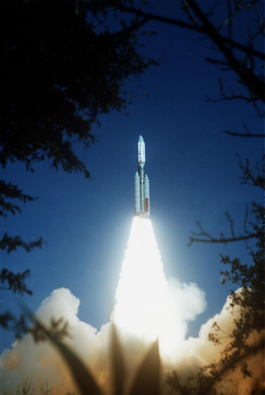
NASA Voyager 2 was launched on Aug. 20, 1977 from the NASA Kennedy Space Center at Cape Canaveral in Florida where it was propelled into space on a Titan/Centaur rocket.
NASA's Voyager 2 spacecraft launched atop its Titan/Centaur-7 launch vehicle from Cape Canaveral Air Force Station in Florida on August 20, 1977, at 10:29 a.m. local time. https://photojournal.jpl.nasa.gov/catalog/PIA21745

NASA's Voyager 2 spacecraft launched atop its Titan/Centaur-7 launch vehicle from Cape Canaveral Air Force Station in Florida on August 20, 1977, at 10:29 a.m. local time. https://photojournal.jpl.nasa.gov/catalog/PIA21744
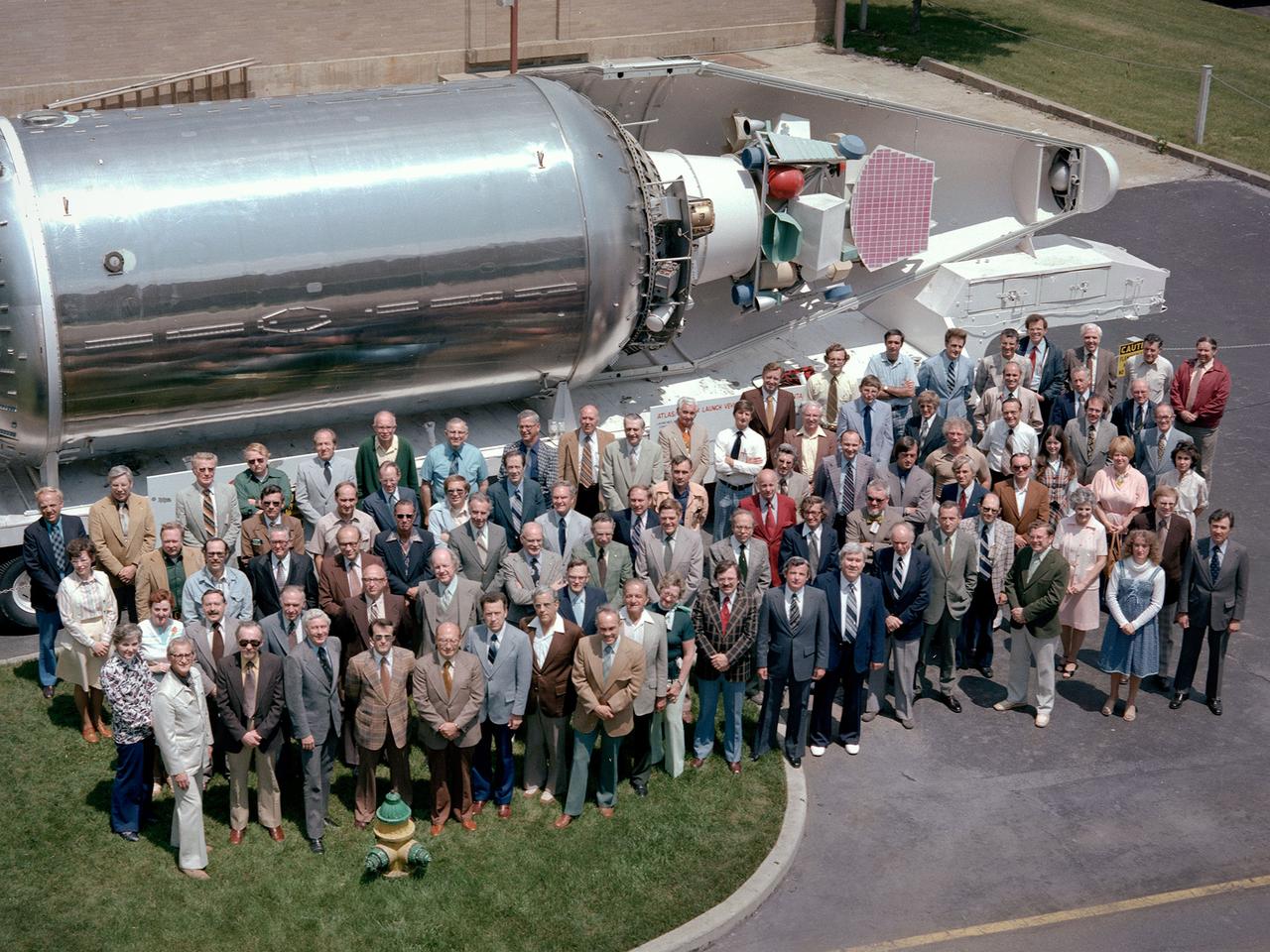
The National Aeronautics and Space Administration (NASA) Lewis Research Center’s Launch Vehicle Directorate in front of a full-scale model of the Centaur second-stage rocket. The photograph was taken to mark Centaur’s fiftieth launch. NASA Lewis managed the Centaur Program since 1962. At that time, the only prior launch attempt ended in failure. Lewis improved the spacecraft and tested it extensively throughout the early 1960s. In May 1966 an Atlas-Centaur sent the Surveyor spacecraft to the moon. It was the first successful soft landing on another planet. The Launch Vehicles Division was formed in 1969 to handle the increasing number of Centaur launches. The Lewis team became experts at integrating the payload with the Centaur and calculating proper trajectories for the missions. Centaur’s first 50 missions included Orbiting Astronomical Observatories, the Mariner 6 and 7 flybys of Mars, Mariner 9 which was the first spacecraft to orbit around another planet, the Pioneer 10 and 11 missions to the outer solar system, the Mariner 10 flyby of Venus and Mercury, the Viking 1 and 2 Mars landers, Voyagers 1 and 2 missions to Jupiter, Saturn, Uranus, and Neptune, and the Pioneer 12 and 13 flights to Venus.
The Voyager 1 aboard the Titan III/Centaur lifted off on September 5, 1977, joining its sister spacecraft, the Voyager 2, on a mission to the outer planets.

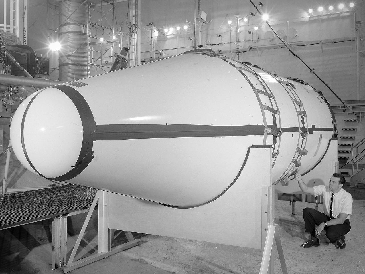
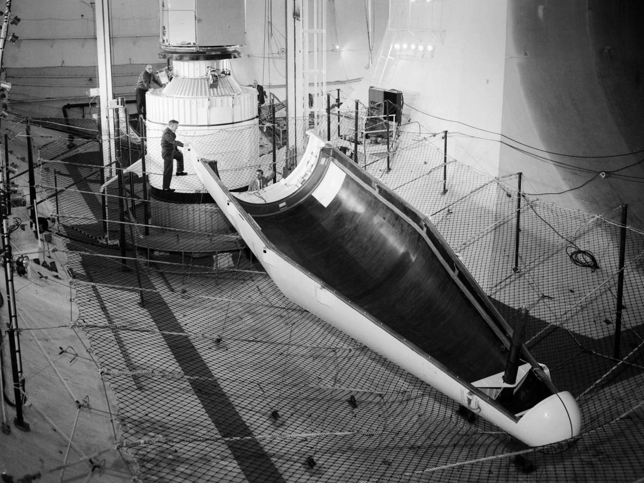
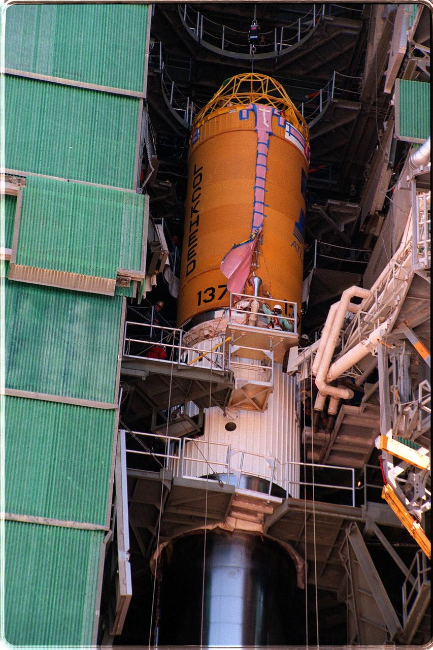
The Centaur Standard Shroud prepared for a jettison test in the Space Power Facility at the National Aeronautics and Space Administration’s (NASA) Plum Brook Station. In the late 1960s NASA engineers were planning the ambitious new Viking mission to send two rover vehicles to the surface of Mars. The Viking rovers were the heaviest payloads ever attempted by the Centaur second-stage rocket. Each Viking was over three times the weight of the Atlas-Centaur’s previous heaviest payload. Consequently, NASA engineers sought to mate the Centaur with the more powerful Titan III booster for the launches. General Dynamics created a new version of the Centaur, D-1T, specifically for Titan. The D-1T’s most significant modification was a completely new shroud designed by Lockheed, called the Centaur Standard Shroud. The conical two-piece covering encapsulated the payload to protect it against adverse conditions and improve the aerodynamics as the launch vehicle passed through the atmosphere. The shroud would be jettisoned when the vehicle reached the edge of space. A string of tests were conducted in Plum Brook’s Nuclear Rocket Dynamics and Control Facility (B-3) during 1973 and 1974. The new shroud performed flawlessly during the actual Viking launches in 1975. Viking 1 and 2 operated on the Martian surface until November 1982 and April 1980, respectively.
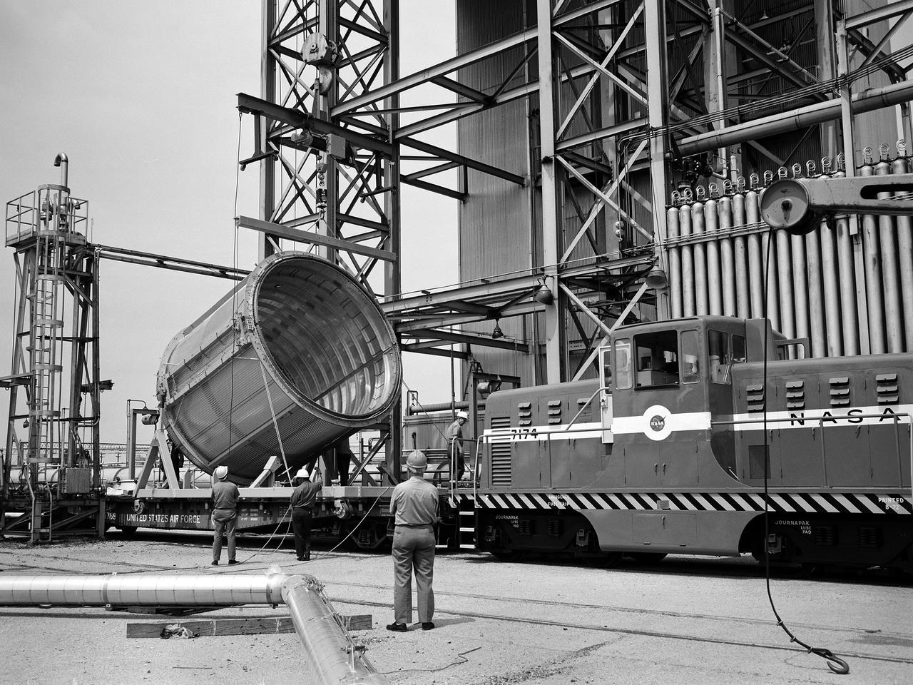
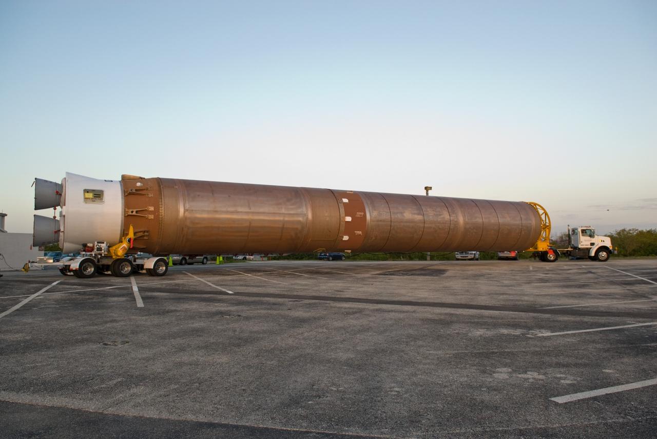
A section of the Centaur Standard Shroud transported to Nuclear Rocket Dynamics and Control Facility, or B-3 Test Stand, at the National Aeronautics and Space Administration’s (NASA) Plum Brook Station. B-3 was built in the early 1960s to test full-scale liquid hydrogen fuel systems in simulated altitude conditions. The facility was used in 1972, however, for testing of the Centaur Standard Shroud’s ejection system. In the late 1960s NASA engineers were planning the ambitious new Viking mission to send two rover vehicles to the surface of Mars. The Viking rovers were the heaviest payloads ever attempted and were over three times the weight of Atlas-Centaur’s previous heaviest payload. Consequently, NASA engineers selected the more powerful the Titan III rocket booster to mate with the Centaur. Concurrently, General Dynamics was in the process of introducing a new Centaur model for Titan—the D-1T. The biggest change for the D-1T was a completely new shroud designed by Lockheed, called the Centaur Standard Shroud. The shroud, its insulation, the Centaur ground-hold purge system, and the hydrogen tank venting system were all studied in B-3. After more than two years of preparations, the tests were run between April and July 1973. The tests determined the ultimate flight loads on two axes, established the Centaur’s load sharing, the level of propellant boiloff during launch holds, and the vent system capacity. The Centaur Standard Shroud performed flawlessly during the August 20 and September 9, 1975 launches of Viking 1 and 2.
Setup of a Surveyor/Atlas/Centaur shroud in the Space Power Chambers for a leak test at the National Aeronautics and Space Administration (NASA) Lewis Research Center. Centaur was a 15,000-pound thrust second-stage rocket designed for the military in 1957 and 1958 by General Dynamics. It was the first major rocket to use the liquid hydrogen technology developed by Lewis in the 1950s. The Centaur Program suffered numerous problems before being transferred to Lewis in 1962. Several test facilities at Lewis’ main campus and Plum Brook Station were built or modified specifically for Centaur, including the Space Power Chambers. In 1961, NASA Lewis management decided to convert its Altitude Wind Tunnel into two large test chambers and later renamed it the Space Power Chambers. The conversion, which took over 2 years, included the removal of the tunnel’s internal components and insertion of bulkheads to seal off the new chambers. The larger chamber, seen here, could simulate altitudes of 100,000 feet. It was used for Centaur shroud separation and propellant management studies until the early 1970s. The leak test in this photograph was likely an attempt to verify that the shroud’s honeycomb shell did not seep any of its internal air when the chamber was evacuated to pressures similar to those found in the upper atmosphere.
NASA's Voyager 2 spacecraft, encapsulated within its payload fairing, is seen on August 5, 1977. It launched atop the Titan/Centaur-7 launch vehicle from Cape Canaveral Air Force Station in Florida on August 20, 1977, at 10:29 a.m. local time. https://photojournal.jpl.nasa.gov/catalog/PIA21742
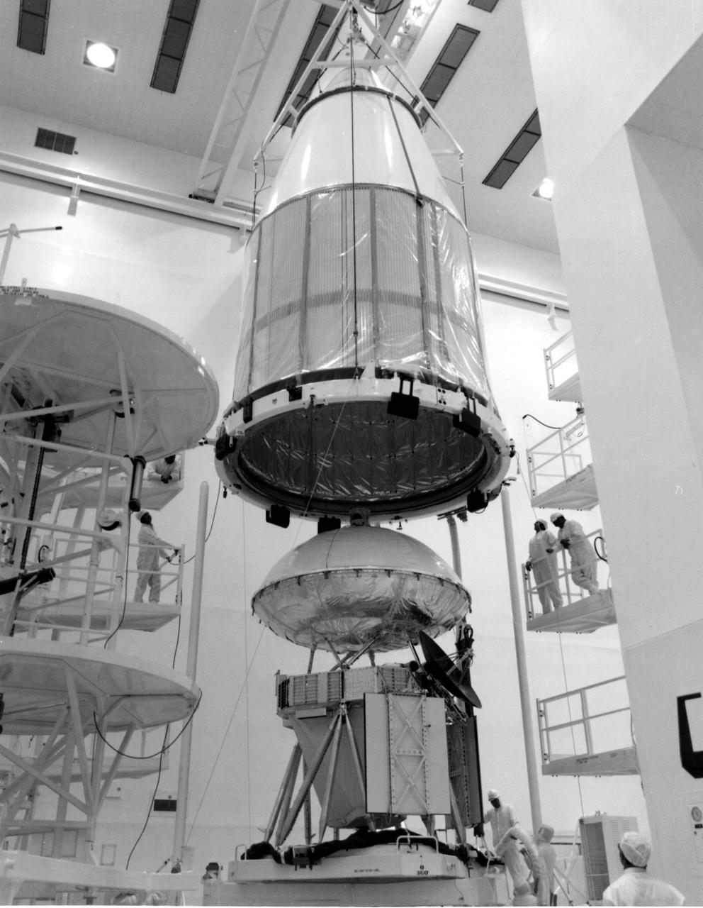
KENNEDY SPACE CENTER, FLA. -- The mated orbiter and lander for Viking A were encapsulated within a Centaur shroud at Spacecraft Assembly and Encapsulation Facility 2 (SAEF-2) today. The spacecraft, one of two to be launched toward Mars atop Titan_Centaurs in August, is to be moved to Launch Complex 41 on March 31 for extensive testing. KSC's Unmanned Launch Operations Directorate is scheduled to launch the twin Vikings during a 10-day period in August.
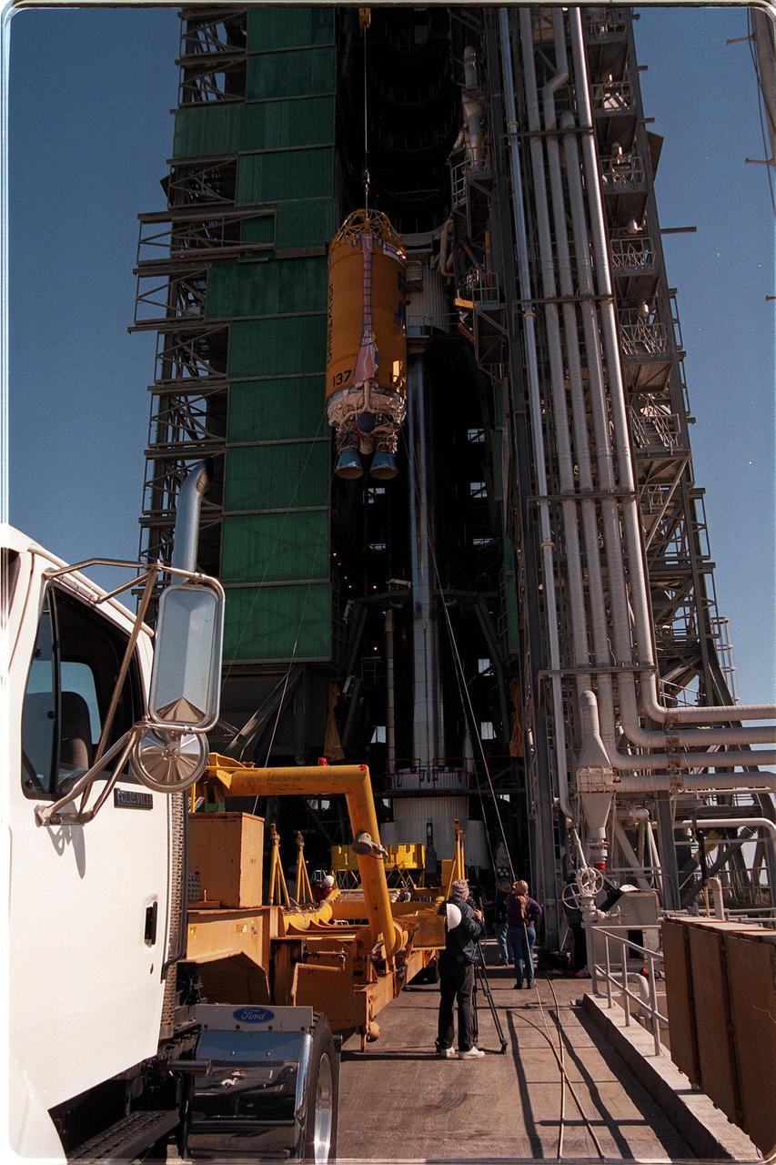
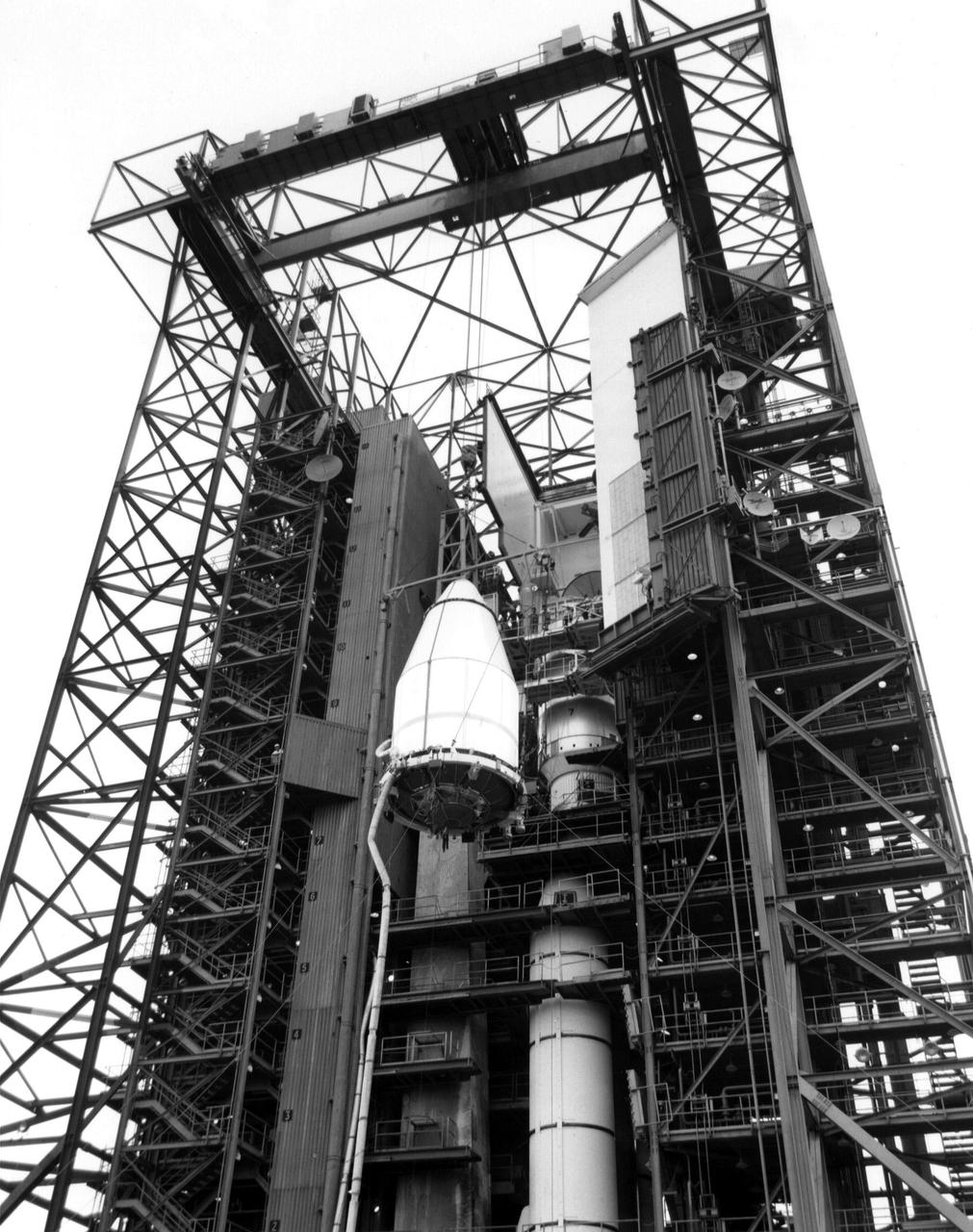
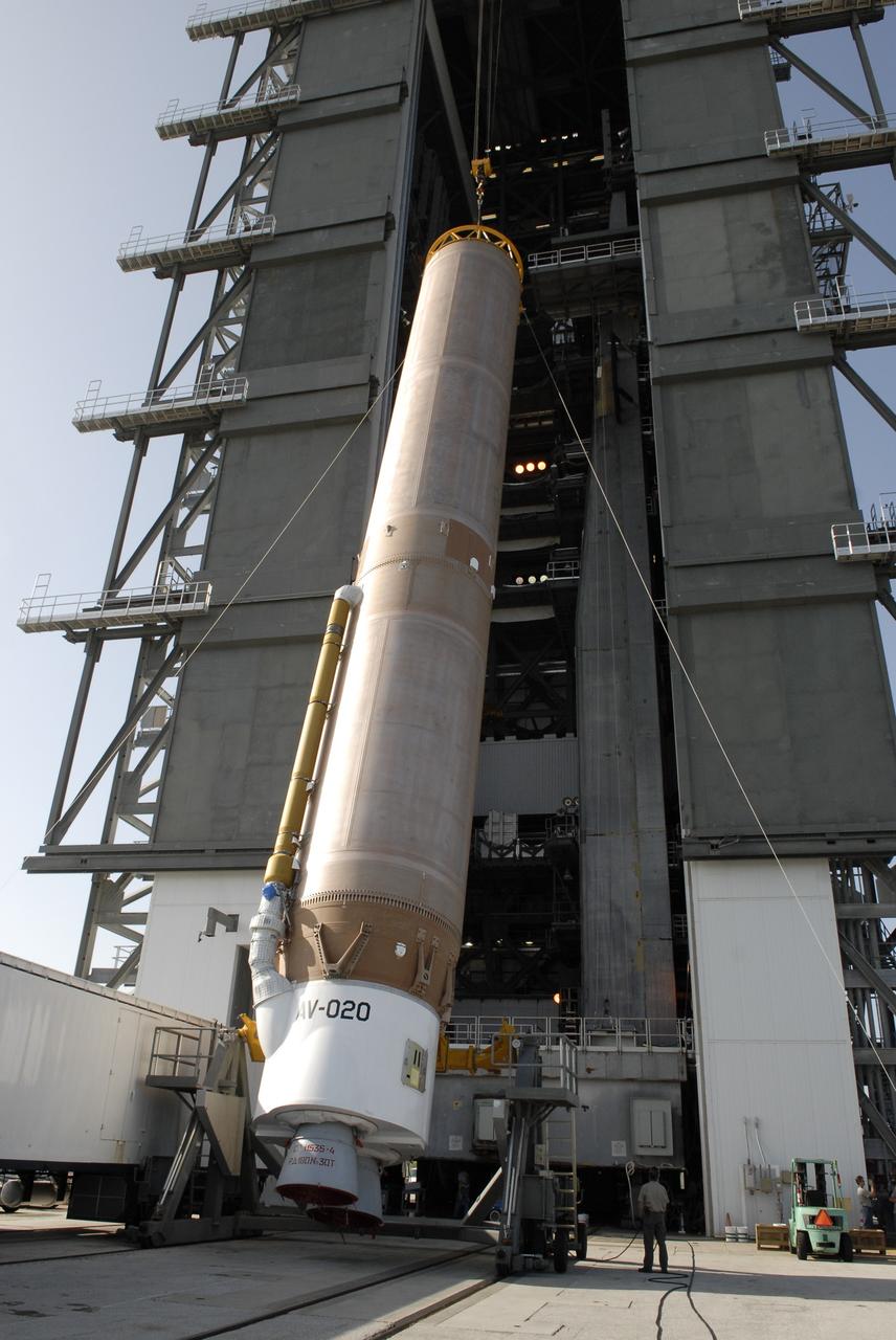
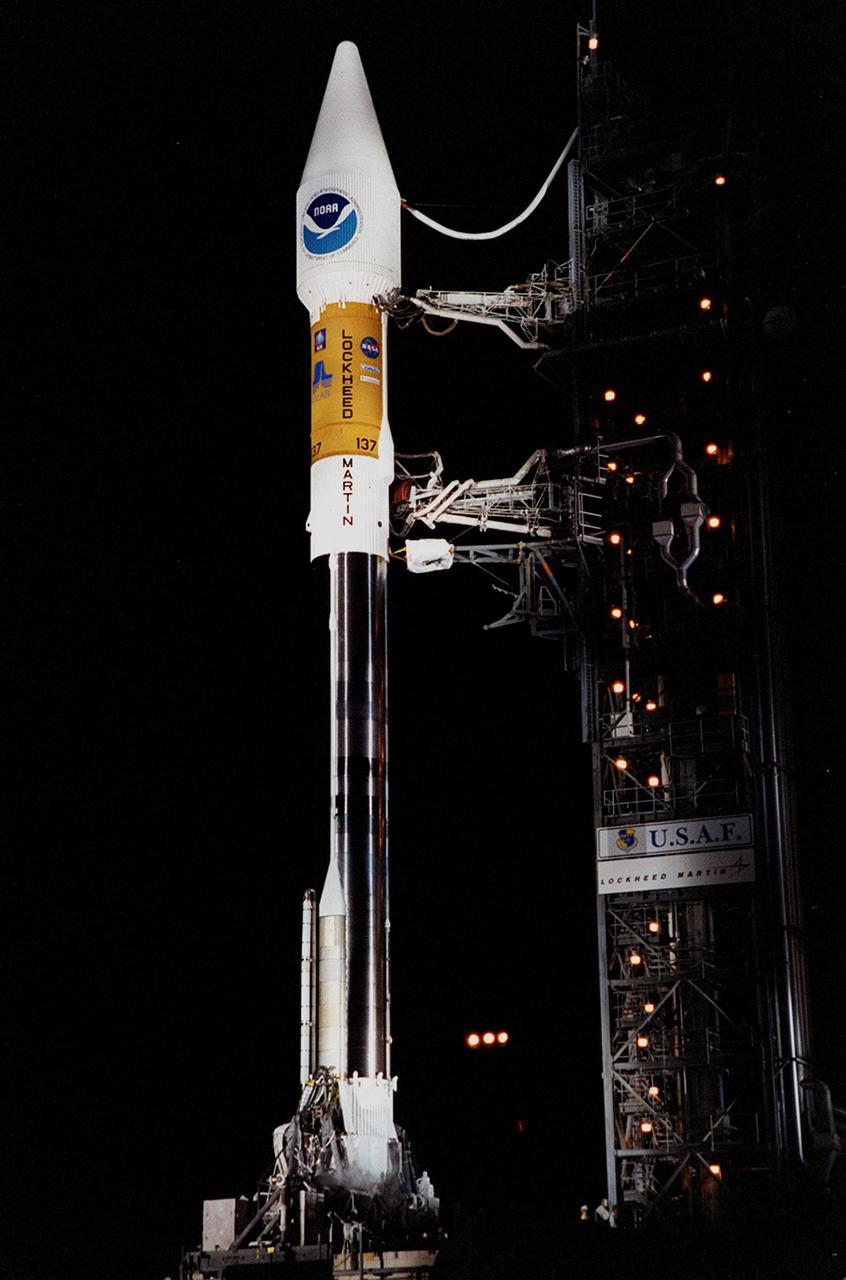
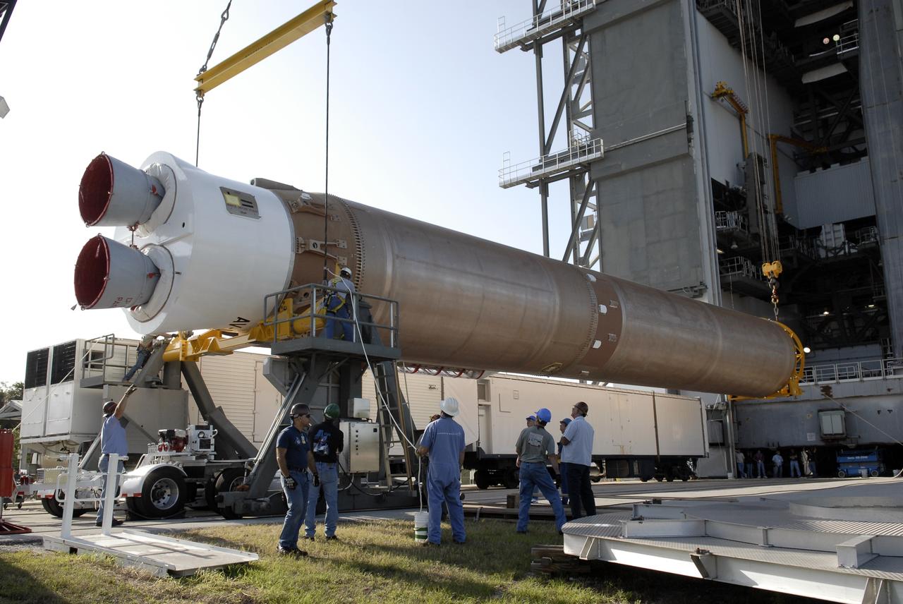
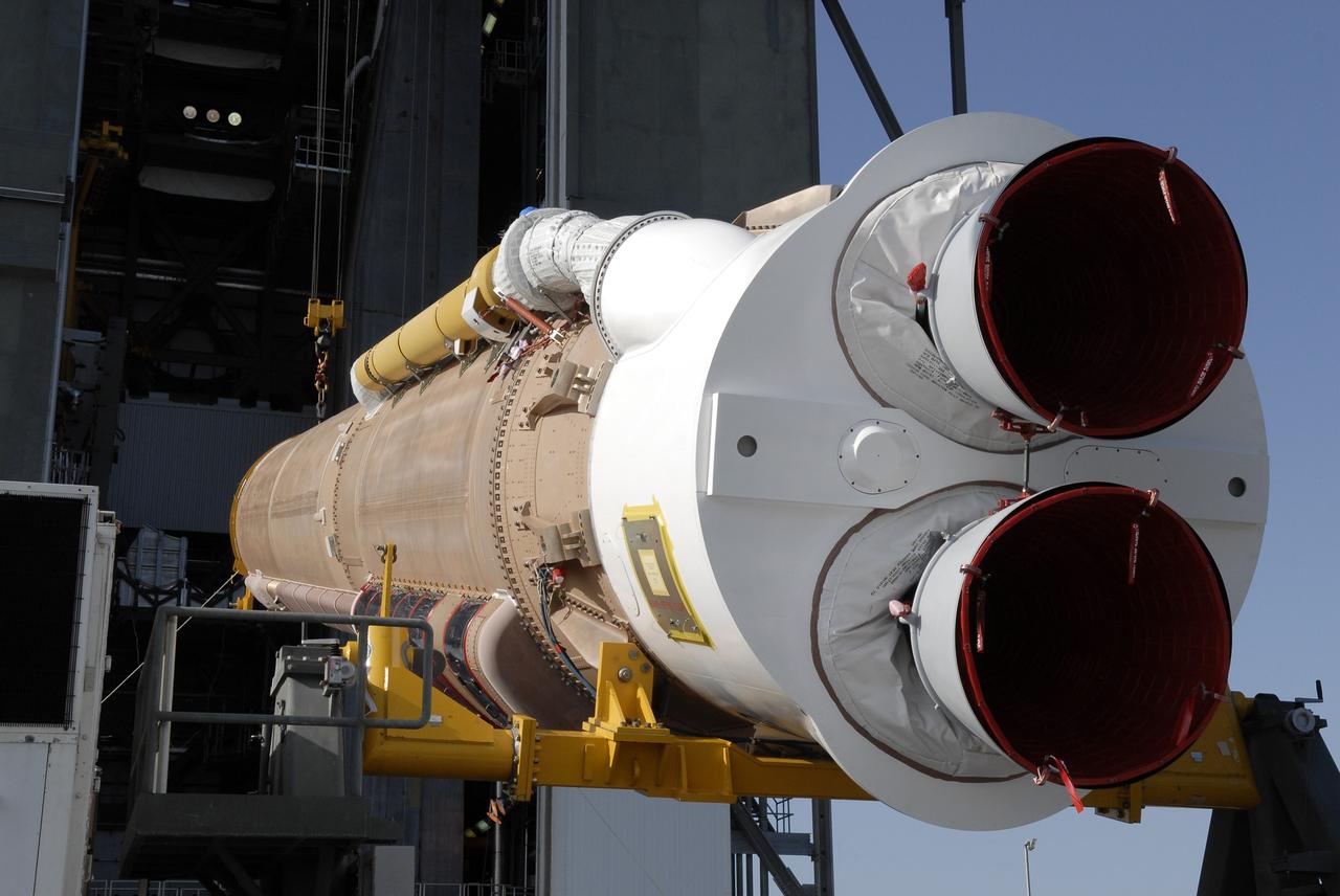
At Launch Pad 36A, Cape Canaveral Air Station, a Centaur upper stage is lifted up the gantry for mating with the lower stage Lockheed Martin Atlas IIA rocket already in place. The Lockheed Martin-manufactured Centaur IIA is powered by two Pratt & Whitney turbopump-fed engines, producing a total thrust of 41,600 pounds. The rocket is scheduled to launch the NASA GOES-L satellite on May 15, at the opening of a launch window which extends from 2:23 to 4:41 a.m. EDT. Once in orbit, the satellite will become GOES-11, joining GOES-8, GOES-9 and GOES-10 in space. The fourth of a new advanced series of geostationary weather satellites for the National Oceanic and Atmospheric Administration (NOAA), GOES-L is a three-axis inertially stabilized spacecraft that will provide pictures and perform atmospheric sounding at the same time. Once launched, the satellite will undergo checkout and then provide backup capabilities for the existing, aging operational satellites
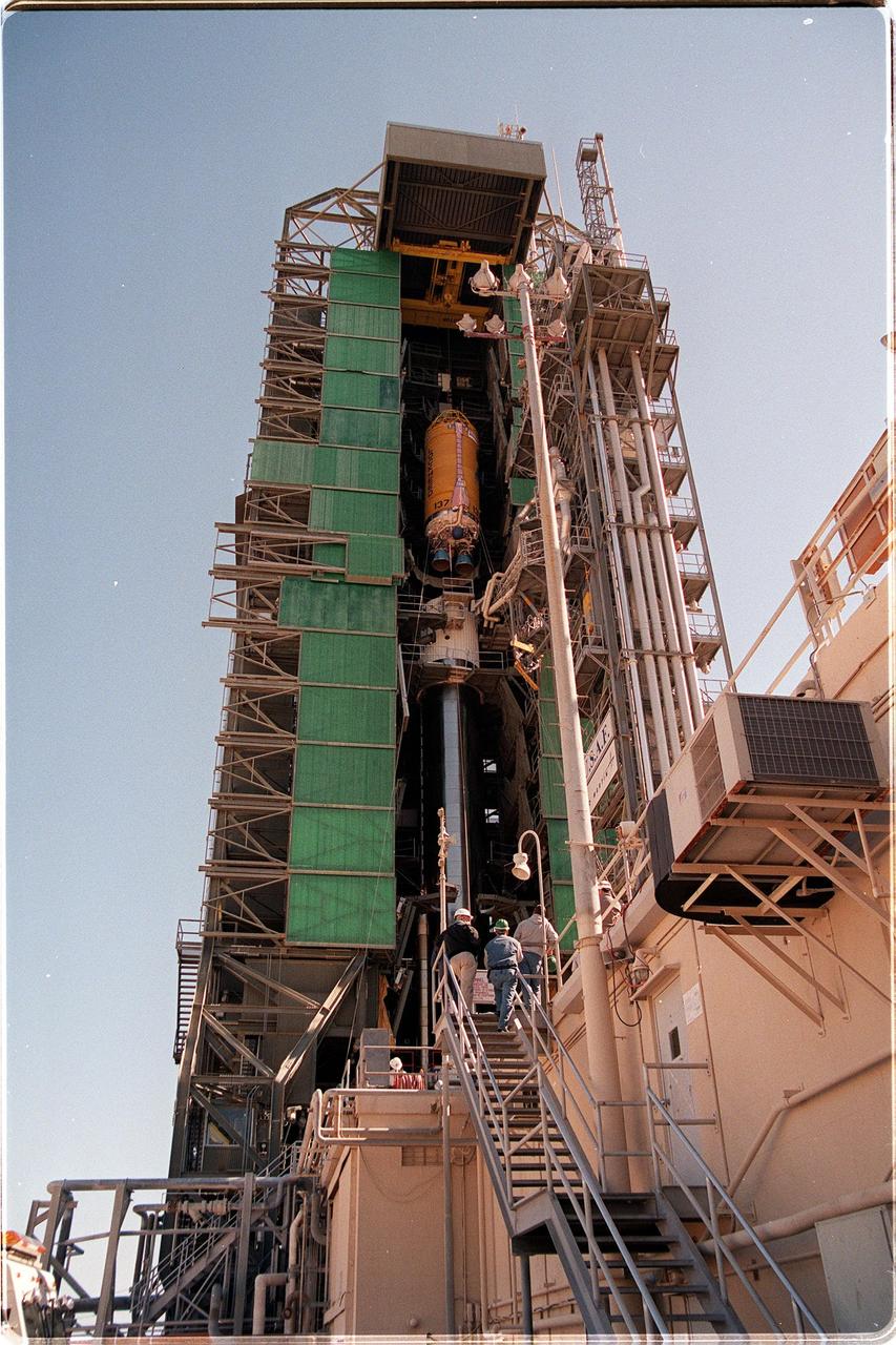
At Launch Pad 36A, Cape Canaveral Air Station, a Centaur upper stage is lifted up the gantry for mating with the lower stage Lockheed Martin Atlas IIA rocket seen behind it. The Lockheed Martin-manufactured Centaur IIA is powered by two Pratt & Whitney turbopump-fed engines, producing a total thrust of 41,600 pounds. The rocket is scheduled to launch the NASA GOES-L satellite on May 15, at the opening of a launch window which extends from 2:23 to 4:41 a.m. EDT. Once in orbit, the satellite will become GOES-11, joining GOES-8, GOES-9 and GOES-10 in space. The fourth of a new advanced series of geostationary weather satellites for the National Oceanic and Atmospheric Administration (NOAA), GOES-L is a three-axis inertially stabilized spacecraft that will provide pictures and perform atmospheric sounding at the same time. Once launched, the satellite will undergo checkout and then provide backup capabilities for the existing, aging operational satellites
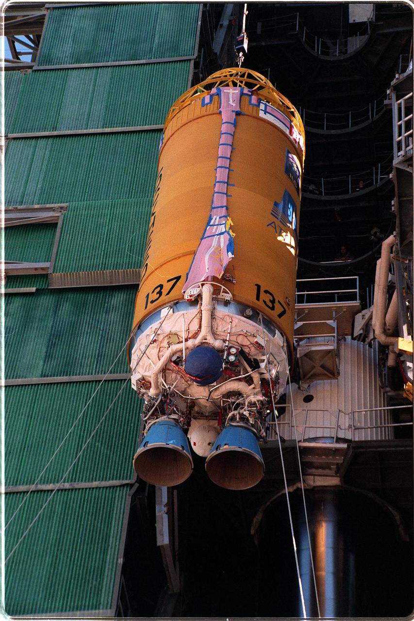
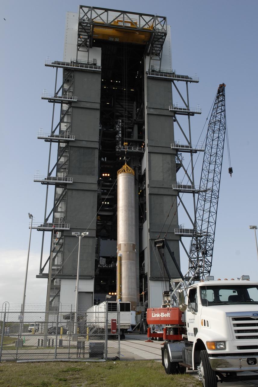
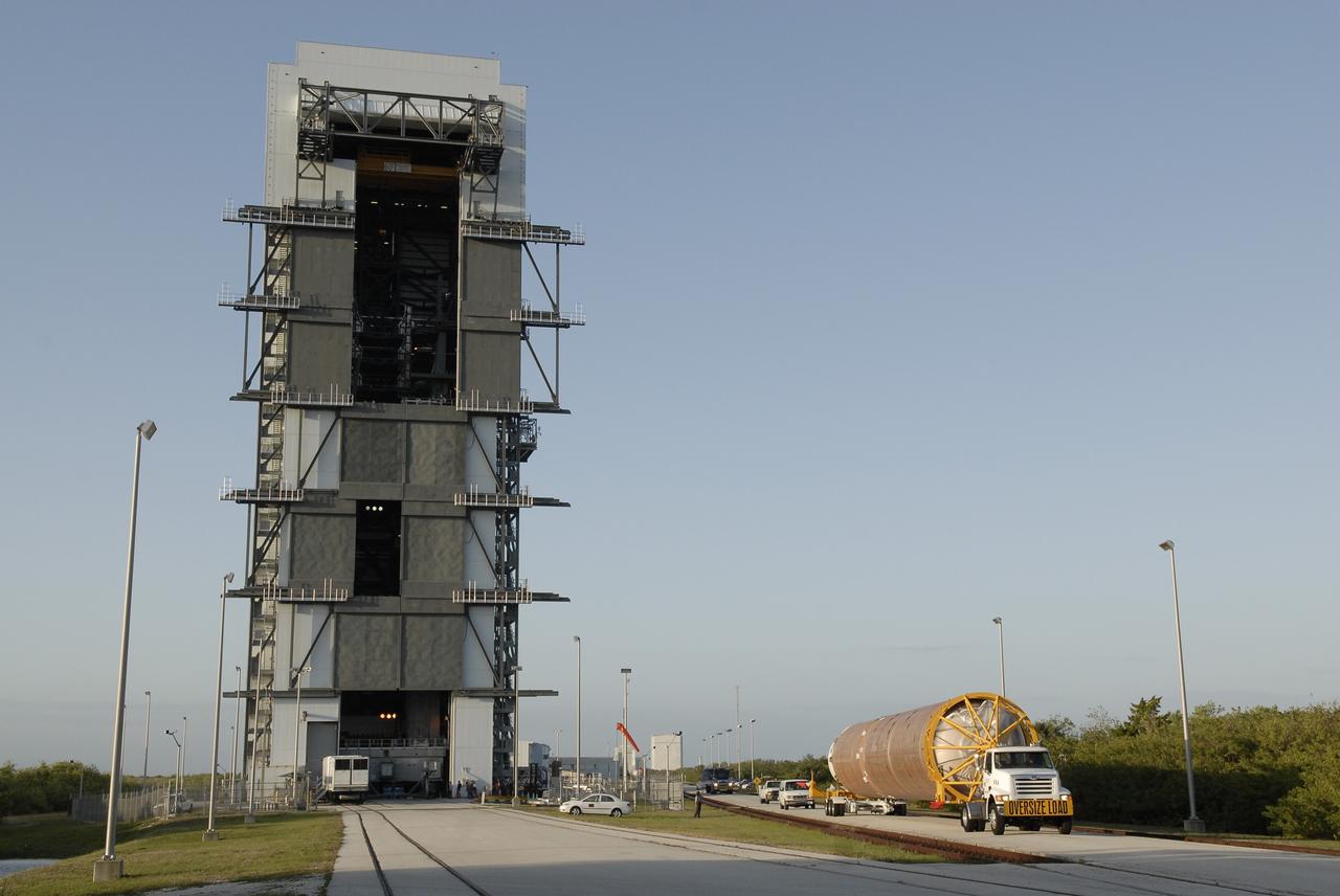
At Launch Pad 36A, Cape Canaveral Air Station, a Centaur upper stage is moved into place above the lower stage Lockheed Martin Atlas IIA rocket. The Lockheed Martin-manufactured Centaur IIA is powered by two Pratt & Whitney turbopump-fed engines, producing a total thrust of 41,600 pounds. The rocket is scheduled to launch the NASA GOES-L satellite on May 15, at the opening of a launch window which extends from 2:23 to 4:41 a.m. EDT. Once in orbit, the satellite will become GOES-11, joining GOES-8, GOES-9 and GOES-10 in space. The fourth of a new advanced series of geostationary weather satellites for the National Oceanic and Atmospheric Administration (NOAA), GOES-L is a three-axis inertially stabilized spacecraft that will provide pictures and perform atmospheric sounding at the same time. Once launched, the satellite will undergo checkout and then provide backup capabilities for the existing, aging operational satellites

This artist's concept depicts the High Energy Astronomy Observatory (HEAO)-2 in orbit. The HEAO-2, the first imaging and largest x-ray telescope built to date, was capable of producing actual photographs of x-ray objects. Shortly after launch, the HEAO-2 was nicknamed the Einstein Observatory by its scientific experimenters in honor of the centernial of the birth of Albert Einstein, whose concepts of relativity and gravitation have influenced much of modern astrophysics, particularly x-ray astronomy. The HEAO-2, designed and developed by TRW, Inc. under the project management of the Marshall Space Flight Center, was launched aboard an Atlas/Centaur launch vehicle on November 13, 1978. The HEAO-2 was originally identified as HEAO-B but the designation was changed once the spacecraft achieved orbit.

Both of the High Energy Astronomy Observatory (HEAO) 2/Einstein Observatory imaging devices were used to observe the Great Nebula in Andromeda, M31. This image is a wide field x-ray view of the center region of M31 by the HEAO-2's Imaging Proportional Counter. The HEAO-2, the first imaging and largest x-ray telescope built to date, was capable of producing actual photographs of x-ray objects. Shortly after launch, the HEAO-2 was nicknamed the Einstein Observatory by its scientific experimenters in honor of the centernial of the birth of Albert Einstein, whose concepts of relativity and gravitation have influenced much of modern astrophysics, particularly x-ray astronomy. The HEAO-2, designed and developed by TRW, Inc. under the project management of the Marshall Space Flight Center, was launched aboard an Atlas/Centaur launch vehicle on November 13, 1978.

This supernova in the constellation Cassiopeia was observed by Tycho Brahe in 1572. In this x-ray image from the High Energy Astronomy Observatory (HEAO-2/Einstein Observatory produced by nearly a day of exposure time, the center region appears filled with emissions that can be resolved into patches or knots of material. However, no central pulsar or other collapsed object can be seen. The HEAO-2, the first imaging and largest x-ray telescope built to date, was capable of producing actual photographs of x-ray objects. Shortly after launch, the HEAO-2 was nicknamed the Einstein Observatory by its scientific experimenters in honor of the centernial of the birth of Albert Einstein, whose concepts of relativity and gravitation have influenced much of modern astrophysics, particularly x-ray astronomy. The HEAO-2, designed and developed by TRW, Inc. under the project management of the Marshall Space Flight Center, was launched aboard an Atlas/Centaur launch vehicle on November 13, 1978.

This is an x-ray image of the Crab Nebula taken with the High Energy Astronomy Observatory (HEAO)-2/Einstein Observatory. The image is demonstrated by a pulsar, which appears as a bright point due to its pulsed x-ray emissions. The strongest region of diffused emissions comes from just northwest of the pulsar, and corresponds closely to the region of brightest visible-light emission. The HEAO-2, the first imaging and largest x-ray telescope built to date, was capable of producing actual photographs of x-ray objects. Shortly after launch, the HEAO-2 was nicknamed the Einstein Observatory by its scientific experimenters in honor of the centernial of the birth of Albert Einstein, whose concepts of relativity and gravitation have influenced much of modern astrophysics, particularly x-ray astronomy. The HEAO-2, designed and developed by TRW, Inc. under the project management of the Marshall Space Flight Center, was launched aboard an Atlas/Centaur launch vehicle on November 13, 1978.

This x-ray photograph of the Supernova remnant Cassiopeia A, taken with the High Energy Astronomy Observatory (HEAO) 2/Einstein Observatory, shows that the regions with fast moving knots of material in the expanding shell are bright and clear. A faint x-ray halo, just outside the bright shell, is interpreted as a shock wave moving ahead of the expanding debris. The HEAO-2, the first imaging and largest x-ray telescope built to date, was capable of producing actual photographs of x-ray objects. Shortly after launch, the HEAO-2 was nicknamed the Einstein Observatory by its scientific experimenters in honor of the centernial of the birth of Albert Einstein, whose concepts of relativity and gravitation have influenced much of modern astrophysics, particularly x-ray astronomy. The HEAO-2, designed and developed by TRW, Inc. under the project management of the Marshall Space Flight Center, was launched aboard an Atlas/Centaur launch vehicle on November 13, 1978.
Researchers at the National Aeronautics and Space Administration (NASA) Lewis Research Center conducted a series of shroud jettison tests for the second Orbiting Astronomical Observatory (OAO-2) in the Space Power Chambers during April 1968. The Orbiting Astronomical Observatory satellites were designed by Goddard Space Flight Center to study and retrieve ultraviolet data on stars and galaxies which earthbound and atmospheric telescopes could not view due to ozone absorption. The shroud jettison system was tested in the Space Power Chambers. In 1961, NASA Lewis management decided to convert its Altitude Wind Tunnel into two large test chambers and later renamed it the Space Power Chambers. The conversion, which took over two years, included removing the tunnel’s internal components and inserting bulkheads to seal off the new chambers. The larger chamber, seen here, could simulate altitudes of 100,000 feet. These chambers were used for a variety of tests on the Centaur second-stage rocket until the early 1970s. The first OAO mission in 1965 failed due to problems with the satellite. OAO-2 would be launched on an Atlas/Centaur with a modified Agena shroud. The new shroud was 18 feet longer than the normal Centaur payload shrouds. This new piece of hardware was successfully qualified during three tests at 90,000 feet altitude in the Space Power Chambers in April 1968. For the first time, x-rays were used to verify the payload clearance once the shroud was sealed. OAO-2 was launched on December 7, 1968 and proved to be an extremely successful mission.
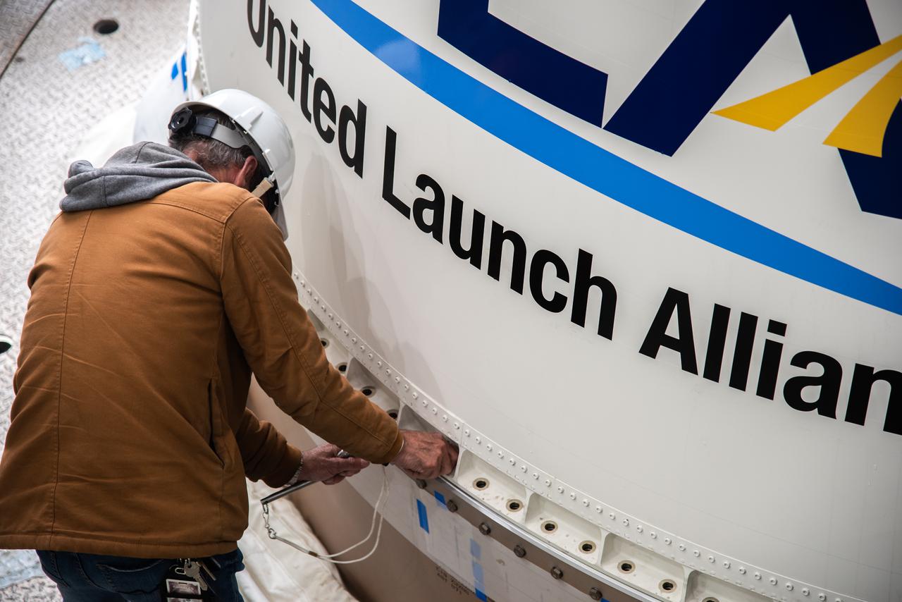
Preparations are underway to lift the interstage and assembly second stage adapters for the United Alliance Atlas V Centaur second stage for NASA’s Landsat 9 mission at Space Launch Complex 3 at Vandenberg Space Force Base in California, on July 14, 2021. The adapters will be stacked atop the Centaur second stage in the Vertical Integration Facility near the launch pad. The Landsat 9 mission will launch atop the Atlas V rocket from Vandenberg in September 2021. The launch is being managed by NASA’s Launch Services Program based at Kennedy Space Center, America’s multiuser spaceport. The Landsat 9 satellite will continue the nearly 50-year legacy of previous Landsat missions. It will monitor key natural and economic resources from orbit. Landsat 9 is managed by the agency’s Goddard Space Flight Center in Greenbelt, Maryland. The satellite will carry two instruments: the Operational Land Imager 2, which collects images of Earth’s landscapes in visible, near infrared and shortwave infrared light, and the Thermal Infrared Sensor 2, which measures the temperature of land surfaces. Like its predecessors, Landsat 9 is a joint mission between NASA and the U.S. Geological Survey.
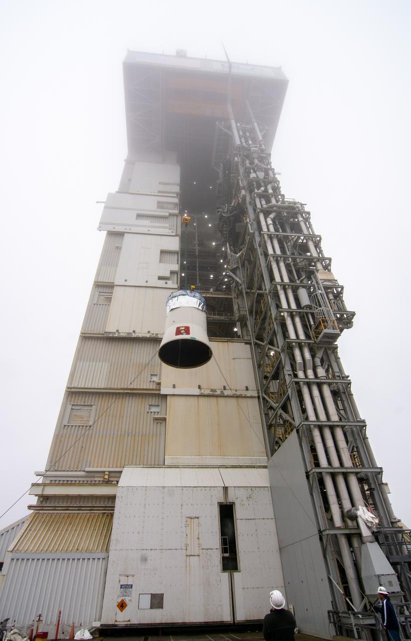
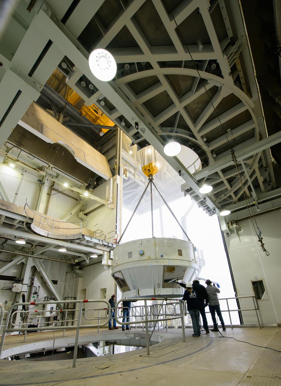
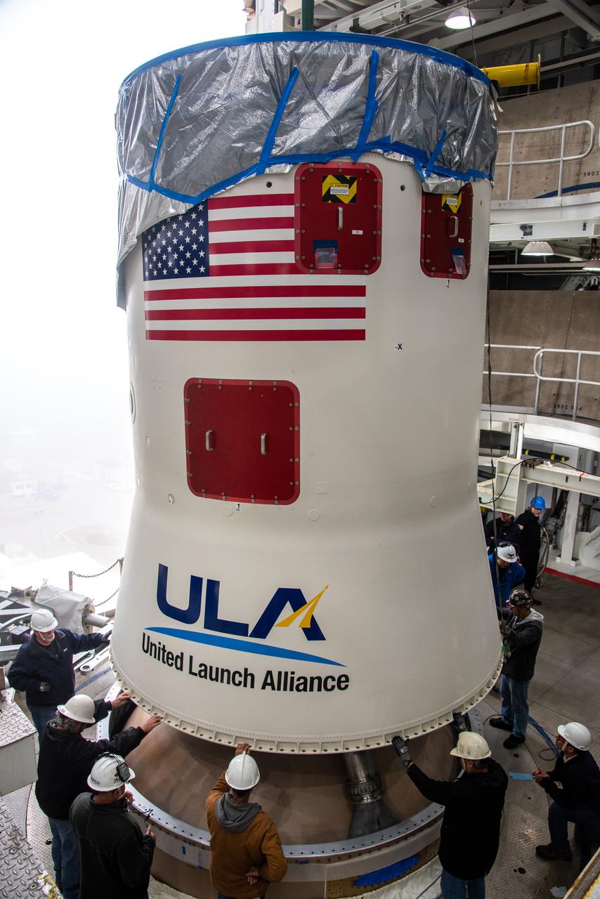
Preparations are underway to lift the United Launch Alliance Centaur second stage for NASA’s Landsat 9 mission into the Vertical Integration Facility at Space Launch Complex 3 at Vandenberg Space Force Base in California, on July 15, 2021. The Centaur will be attached to the top of the Atlas V booster. The Landsat 9 mission will launch atop the Atlas V rocket from Vandenberg in September 2021. The launch is being managed by NASA’s Launch Services Program based at Kennedy Space Center, America’s multiuser spaceport. The Landsat 9 satellite will continue the nearly 50-year legacy of previous Landsat missions. It will monitor key natural and economic resources from orbit. Landsat 9 is managed by the agency’s Goddard Space Flight Center in Greenbelt, Maryland. The satellite will carry two instruments: the Operational Land Imager 2, which collects images of Earth’s landscapes in visible, near infrared and shortwave infrared light, and the Thermal Infrared Sensor 2, which measures the temperature of land surfaces. Like its predecessors, Landsat 9 is a joint mission between NASA and the U.S. Geological Survey.
The interstage and assembly second stage adapters for the United Alliance Centaur Atlas V for NASA’s Landsat 9 mission are lifted by crane from a flatbed truck at Space Launch Complex 3 at Vandenberg Space Force Base in California, on July 14, 2021. The adapters will be stacked atop the Centaur second stage in the Vertical Integration Facility near the launch pad. The Landsat 9 mission will launch atop the Atlas V rocket from Vandenberg in September 2021. The launch is being managed by NASA’s Launch Services Program based at Kennedy Space Center, America’s multiuser spaceport. The Landsat 9 satellite will continue the nearly 50-year legacy of previous Landsat missions. It will monitor key natural and economic resources from orbit. Landsat 9 is managed by the agency’s Goddard Space Flight Center in Greenbelt, Maryland. The satellite will carry two instruments: the Operational Land Imager 2, which collects images of Earth’s landscapes in visible, near infrared and shortwave infrared light, and the Thermal Infrared Sensor 2, which measures the temperature of land surfaces. Like its predecessors, Landsat 9 is a joint mission between NASA and the U.S. Geological Survey.

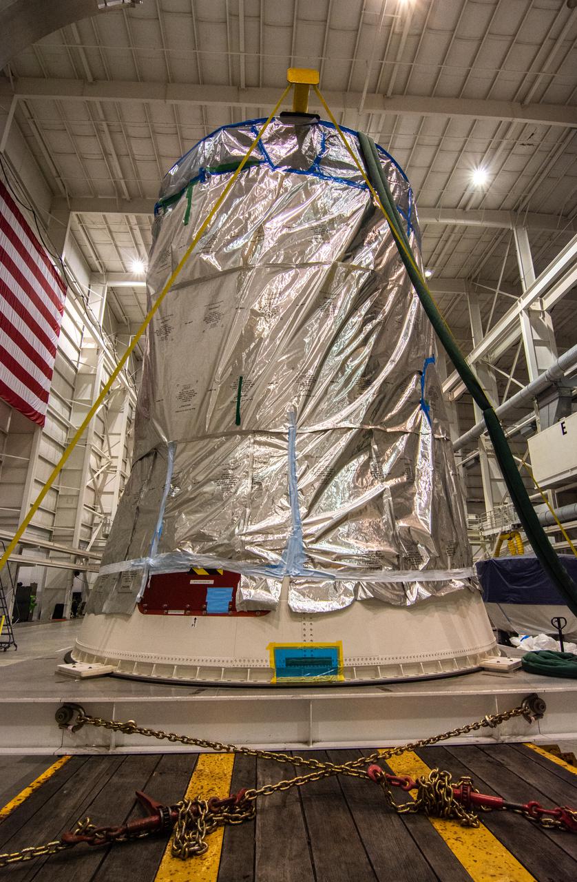
A special lifting device is used to move the United Launch Alliance Centaur second stage for NASA’s Landsat 9 mission to the vertical position for lifting into the Vertical Integration Facility at Space Launch Complex 3 at Vandenberg Space Force Base in California, on July 15, 2021. The Centaur will be attached to the top of the Atlas V booster. The Landsat 9 mission will launch atop the Atlas V rocket from Vandenberg in September 2021. The launch is being managed by NASA’s Launch Services Program based at Kennedy Space Center, America’s multiuser spaceport. The Landsat 9 satellite will continue the nearly 50-year legacy of previous Landsat missions. It will monitor key natural and economic resources from orbit. Landsat 9 is managed by the agency’s Goddard Space Flight Center in Greenbelt, Maryland. The satellite will carry two instruments: the Operational Land Imager 2, which collects images of Earth’s landscapes in visible, near infrared and shortwave infrared light, and the Thermal Infrared Sensor 2, which measures the temperature of land surfaces. Like its predecessors, Landsat 9 is a joint mission between NASA and the U.S. Geological Survey.
The interstage and assembly second stage adapters for the United Alliance Atlas V Centaur second stage for NASA’s Landsat 9 mission are lifted by crane at Space Launch Complex 3 at Vandenberg Space Force Base in California, on July 14, 2021. The adapters will be stacked atop the Centaur second stage in the Vertical Integration Facility near the launch pad. The Landsat 9 mission will launch atop the Atlas V rocket from Vandenberg in September 2021. The launch is being managed by NASA’s Launch Services Program based at Kennedy Space Center, America’s multiuser spaceport. The Landsat 9 satellite will continue the nearly 50-year legacy of previous Landsat missions. It will monitor key natural and economic resources from orbit. Landsat 9 is managed by the agency’s Goddard Space Flight Center in Greenbelt, Maryland. The satellite will carry two instruments: the Operational Land Imager 2, which collects images of Earth’s landscapes in visible, near infrared and shortwave infrared light, and the Thermal Infrared Sensor 2, which measures the temperature of land surfaces. Like its predecessors, Landsat 9 is a joint mission between NASA and the U.S. Geological Survey.
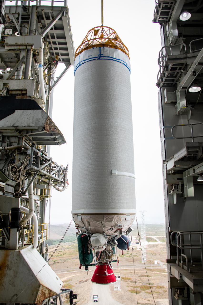
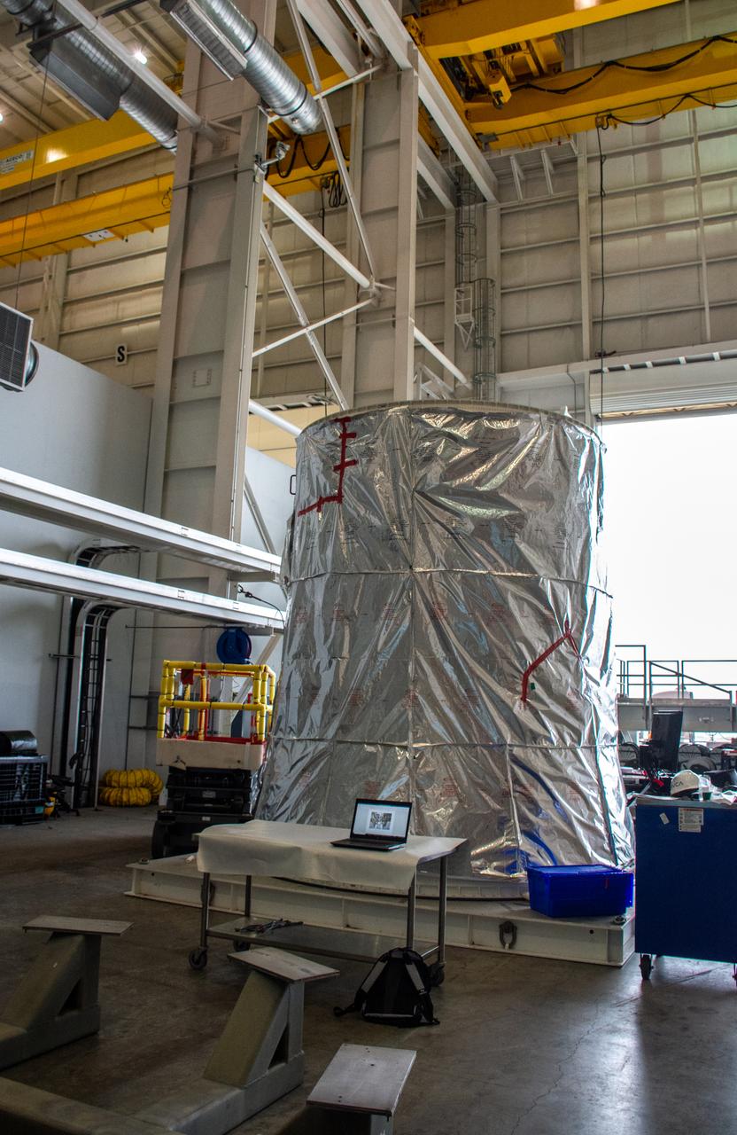
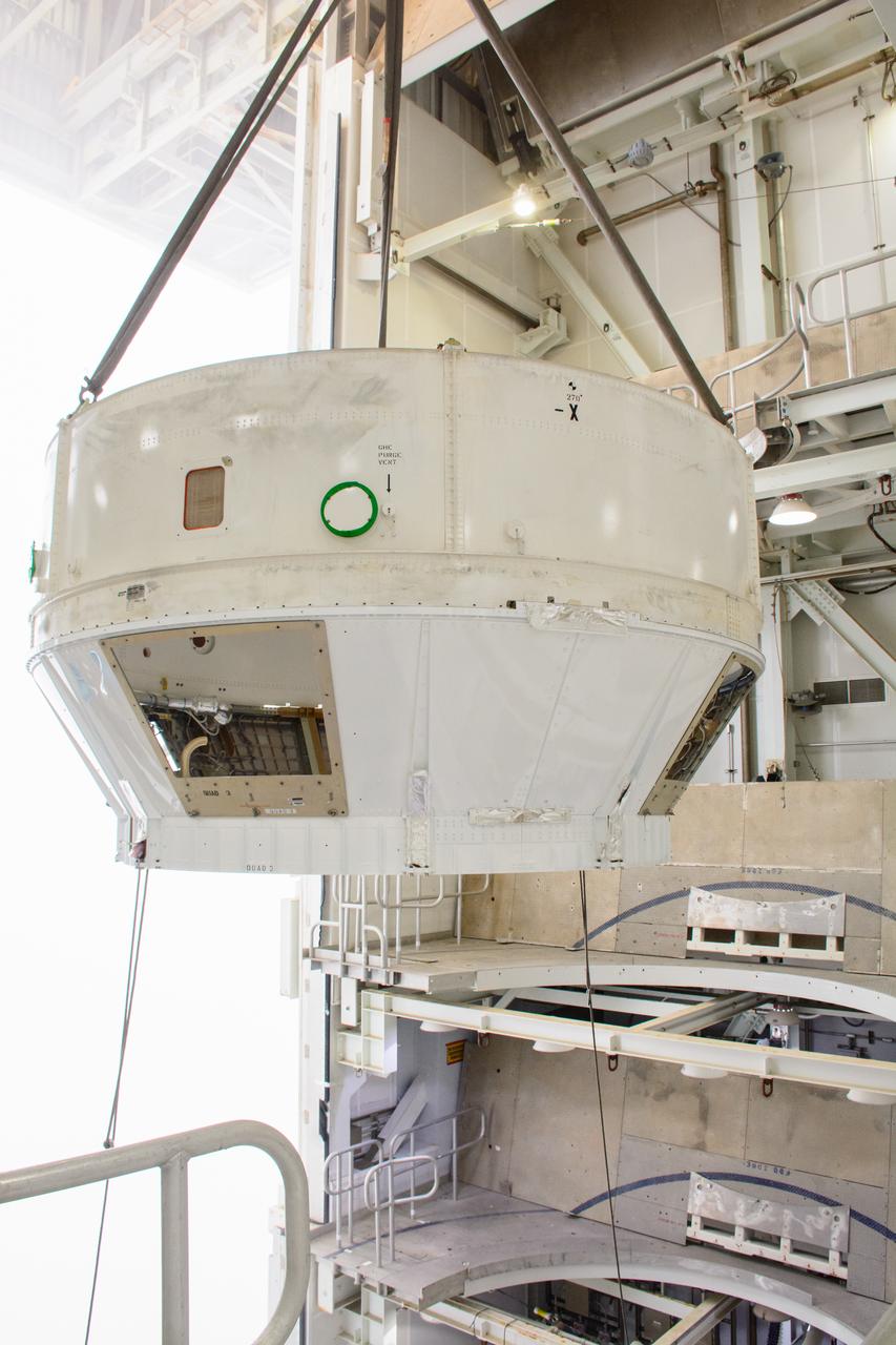
The United Launch Alliance Centaur second stage for NASA’s Landsat 9 mission seems suspended in midair in this view from inside the Vertical Integration Facility at Space Launch Complex 3 at Vandenberg Space Force Base in California, on July 15, 2021. The Centaur will be moved into the integration facility and attached to the top of the Atlas V booster. The Landsat 9 mission will launch atop the Atlas V rocket from Vandenberg in September 2021. The launch is being managed by NASA’s Launch Services Program based at Kennedy Space Center, America’s multiuser spaceport. The Landsat 9 satellite will continue the nearly 50-year legacy of previous Landsat missions. It will monitor key natural and economic resources from orbit. Landsat 9 is managed by the agency’s Goddard Space Flight Center in Greenbelt, Maryland. The satellite will carry two instruments: the Operational Land Imager 2, which collects images of Earth’s landscapes in visible, near infrared and shortwave infrared light, and the Thermal Infrared Sensor 2, which measures the temperature of land surfaces. Like its predecessors, Landsat 9 is a joint mission between NASA and the U.S. Geological Survey.
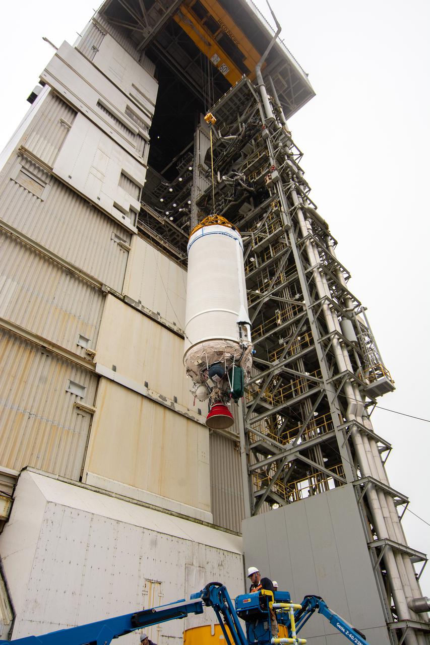
The United Launch Alliance Centaur second stage for NASA’s Landsat 9 mission is lifted high by crane for transfer into the Vertical Integration Facility at Space Launch Complex 3 at Vandenberg Space Force Base in California, on July 15, 2021. The Centaur will be attached to the top of the Atlas V rocket. The Landsat 9 mission will launch atop the Atlas V rocket from Vandenberg in September 2021. The launch is being managed by NASA’s Launch Services Program based at Kennedy Space Center, America’s multiuser spaceport. The Landsat 9 satellite will continue the nearly 50-year legacy of previous Landsat missions. It will monitor key natural and economic resources from orbit. Landsat 9 is managed by the agency’s Goddard Space Flight Center in Greenbelt, Maryland. The satellite will carry two instruments: the Operational Land Imager 2, which collects images of Earth’s landscapes in visible, near infrared and shortwave infrared light, and the Thermal Infrared Sensor 2, which measures the temperature of land surfaces. Like its predecessors, Landsat 9 is a joint mission between NASA and the U.S. Geological Survey.
Preparations are underway to lift the interstage and assembly second stage adapters for the United Alliance Atlas V Centaur second stage for NASA’s Landsat 9 mission at Space Launch Complex 3 at Vandenberg Space Force Base in California, on July 14, 2021. The adapters will be stacked atop the Centaur second stage in the Vertical Integration Facility near the launch pad. The Landsat 9 mission will launch atop the Atlas V rocket from Vandenberg in September 2021. The launch is being managed by NASA’s Launch Services Program based at Kennedy Space Center, America’s multiuser spaceport. The Landsat 9 satellite will continue the nearly 50-year legacy of previous Landsat missions. It will monitor key natural and economic resources from orbit. Landsat 9 is managed by the agency’s Goddard Space Flight Center in Greenbelt, Maryland. The satellite will carry two instruments: the Operational Land Imager 2, which collects images of Earth’s landscapes in visible, near infrared and shortwave infrared light, and the Thermal Infrared Sensor 2, which measures the temperature of land surfaces. Like its predecessors, Landsat 9 is a joint mission between NASA and the U.S. Geological Survey.
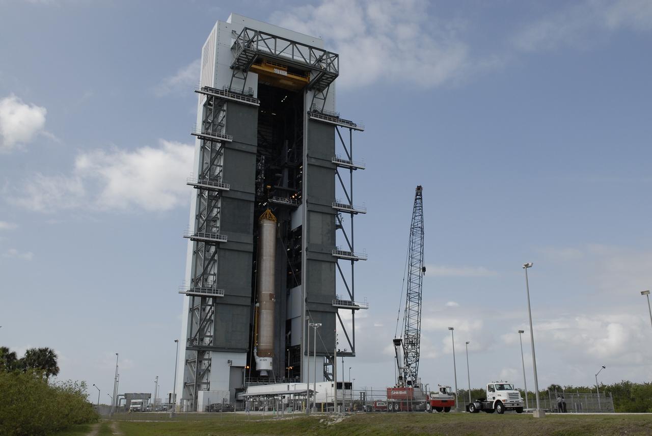
CAPE CANAVERAL, Fla. –– When the Atlas V first stage is raised to vertical, it will be lifted into the Vertical Integration Facility on Cape Canaveral Air Force Station's Launch Complex 41. The Atlas V/Centaur is the launch vehicle for the Lunar Reconnaissance Orbiter, or LRO. The orbiter will carry seven instruments to provide scientists with detailed maps of the lunar surface and enhance our understanding of the moon's topography, lighting conditions, mineralogical composition and natural resources. Information gleaned from LRO will be used to select safe landing sites, determine locations for future lunar outposts and help mitigate radiation dangers to astronauts. Launch of LRO is targeted no earlier than June 2. Photo credit: NASA/Kim Shiflett

The Atlas II/Centaur rocket carrying the NASA/NOAA weather satellite GOES-L is revealed as the tower rolls back before launch. The primary objective of the GOES-L is to provide a full capability satellite in an on-orbit storage condition, in order to assure NOAA continuity in services from a two-satellite constellation. Launch services are being provided by the 45th Space Wing. Liftoff is targeted to occur at the opening of a launch window extending from 2:27 5:53 a.m. EDT, a duration of three hours and 27 minutes. Launch will occur from Pad A at Complex 36 on Cape Canaveral Air Force Station
CAPE CANAVERAL, Fla. –– On Cape Canaveral Air Force Station's Launch Complex 41, the Atlas V first stage is being moved into the Vertical Integration Facility. The Atlas V/Centaur is the launch vehicle for the Lunar Reconnaissance Orbiter, or LRO. The orbiter will carry seven instruments to provide scientists with detailed maps of the lunar surface and enhance our understanding of the moon's topography, lighting conditions, mineralogical composition and natural resources. Information gleaned from LRO will be used to select safe landing sites, determine locations for future lunar outposts and help mitigate radiation dangers to astronauts. Launch of LRO is targeted no earlier than June 2. Photo credit: NASA/Kim Shiflett
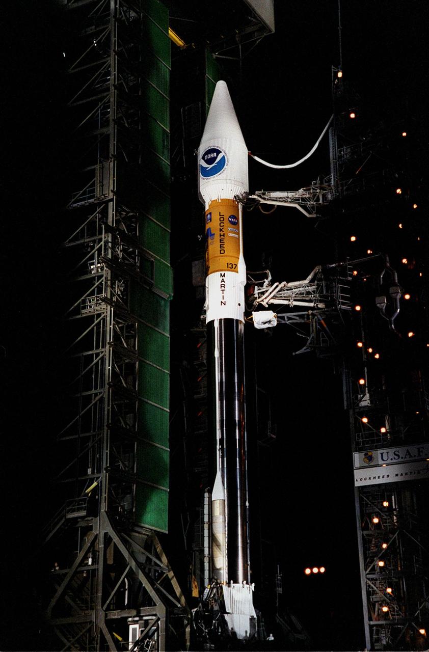
The Atlas II/Centaur rocket carrying the NASA/NOAA weather satellite GOES-L is revealed as the tower rolls back before launch. The primary objective of the GOES-L is to provide a full capability satellite in an on-orbit storage condition, in order to assure NOAA continuity in services from a two-satellite constellation. Launch services are being provided by the 45th Space Wing. Liftoff is targeted to occur at the opening of a launch window extending from 2:27 5:53 a.m. EDT, a duration of three hours and 27 minutes. Launch will occur from Pad A at Complex 36 on Cape Canaveral Air Force Station

The Atlas II/Centaur rocket carrying the NASA/NOAA weather satellite GOES-L is revealed after the tower was rolled back before launch. The primary objective of the GOES-L is to provide a full capability satellite in an on-orbit storage condition, in order to assure NOAA continuity in services from a two-satellite constellation. Launch services are being provided by the 45th Space Wing. Liftoff is targeted to occur at the opening of a launch window extending from 2:27 5:53 a.m. EDT, a duration of three hours and 27 minutes. Launch will occur from Pad A at Complex 36 on Cape Canaveral Air Force Station
CAPE CANAVERAL, Fla. –– The Atlas V first stage arrives at the Vertical Integration Facility on Cape Canaveral Air Force Station's Launch Complex 41. The Atlas V/Centaur is the launch vehicle for the Lunar Reconnaissance Orbiter, or LRO. The orbiter will carry seven instruments to provide scientists with detailed maps of the lunar surface and enhance our understanding of the moon's topography, lighting conditions, mineralogical composition and natural resources. Information gleaned from LRO will be used to select safe landing sites, determine locations for future lunar outposts and help mitigate radiation dangers to astronauts. Launch of LRO is targeted no earlier than June 2. Photo credit: NASA/Kim Shiflett
The Atlas II/Centaur rocket carrying the NASA/NOAA weather satellite GOES-L is revealed after the tower was rolled back before launch. The primary objective of the GOES-L is to provide a full capability satellite in an on-orbit storage condition, in order to assure NOAA continuity in services from a two-satellite constellation. Launch services are being provided by the 45th Space Wing. Liftoff is targeted to occur at the opening of a launch window extending from 2:27 5:53 a.m. EDT, a duration of three hours and 27 minutes. Launch will occur from Pad A at Complex 36 on Cape Canaveral Air Force Station
CAPE CANAVERAL, Fla. –– On Cape Canaveral Air Force Station's Launch Complex 41, the Atlas V first stage is being moved into the Vertical Integration Facility. The Atlas V/Centaur is the launch vehicle for the Lunar Reconnaissance Orbiter, or LRO. The orbiter will carry seven instruments to provide scientists with detailed maps of the lunar surface and enhance our understanding of the moon's topography, lighting conditions, mineralogical composition and natural resources. Information gleaned from LRO will be used to select safe landing sites, determine locations for future lunar outposts and help mitigate radiation dangers to astronauts. Launch of LRO is targeted no earlier than June 2. Photo credit: NASA/Kim Shiflett
CAPE CANAVERAL, Fla. –– The Atlas V first stage arrives at the Vertical Integration Facility on Cape Canaveral Air Force Station's Launch Complex 41. The Atlas V/Centaur is the launch vehicle for the Lunar Reconnaissance Orbiter, or LRO. The orbiter will carry seven instruments to provide scientists with detailed maps of the lunar surface and enhance our understanding of the moon's topography, lighting conditions, mineralogical composition and natural resources. Information gleaned from LRO will be used to select safe landing sites, determine locations for future lunar outposts and help mitigate radiation dangers to astronauts. Launch of LRO is targeted no earlier than June 2. Photo credit: NASA/Kim Shiflett
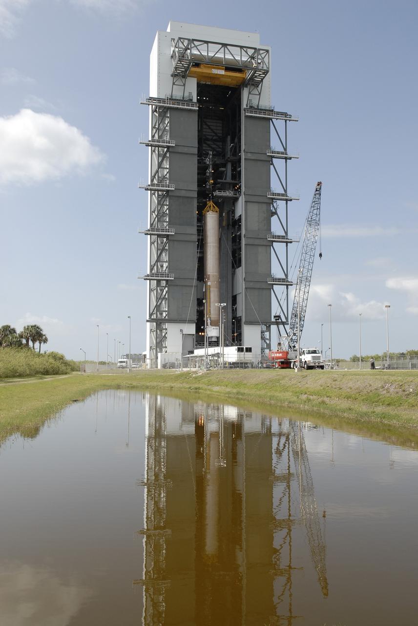
CAPE CANAVERAL, Fla. –– On Cape Canaveral Air Force Station's Launch Complex 41, the Atlas V first stage is being moved into the Vertical Integration Facility. The Atlas V/Centaur is the launch vehicle for the Lunar Reconnaissance Orbiter, or LRO. The orbiter will carry seven instruments to provide scientists with detailed maps of the lunar surface and enhance our understanding of the moon's topography, lighting conditions, mineralogical composition and natural resources. Information gleaned from LRO will be used to select safe landing sites, determine locations for future lunar outposts and help mitigate radiation dangers to astronauts. Launch of LRO is targeted no earlier than June 2. Photo credit: NASA/Kim Shiflett
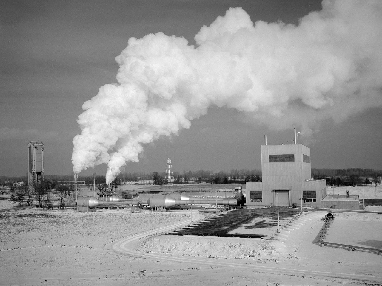
The Space Propulsion Research Facility, better known as B-2, operating at the National Aeronautics and Space Administration’s (NASA) Plum Brook Station in Sandusky, Ohio. B-2 is the world's only high altitude test facility capable of full-scale rocket engine and launch vehicle system level tests. It was created to test rocket propulsion systems with up to 100,000 pounds of thrust in a simulated space environment. The facility has the unique ability to maintain a vacuum at the rocket’s nozzle while the engine is firing. The rocket fires into a 120-foot deep spray chamber which cools the exhaust before it is ejected outside the facility. B-2 simulated space using giant diffusion pumps to reduce chamber pressure, nitrogen-filled cold walls create cryogenic temperatures, and quartz lamps replicate the radiation of the sun. This photograph shows the facility undergoing check-out runs prior to its first test in late 1969.The 38-foot diameter and 62-foot tall vacuum chamber is inside the high-bay on the right. Below that is a 67-foot diameter and 120-foot deep spray chamber. The hot rocket exhaust is cooled in the chamber by a spray of 250,000 gallons of water per minute. B-2’s first test was a hot firing of Centaur D-1A rocket on December 18, 1969. Since then the facility has fired more than 100 Pratt and Whitney RL-10 engines during the Centaur development, 80 current RL-10B-2 engines for Delta-3 development, and another 12 RL-10B-2s for the Delta 3 Upper Stage.
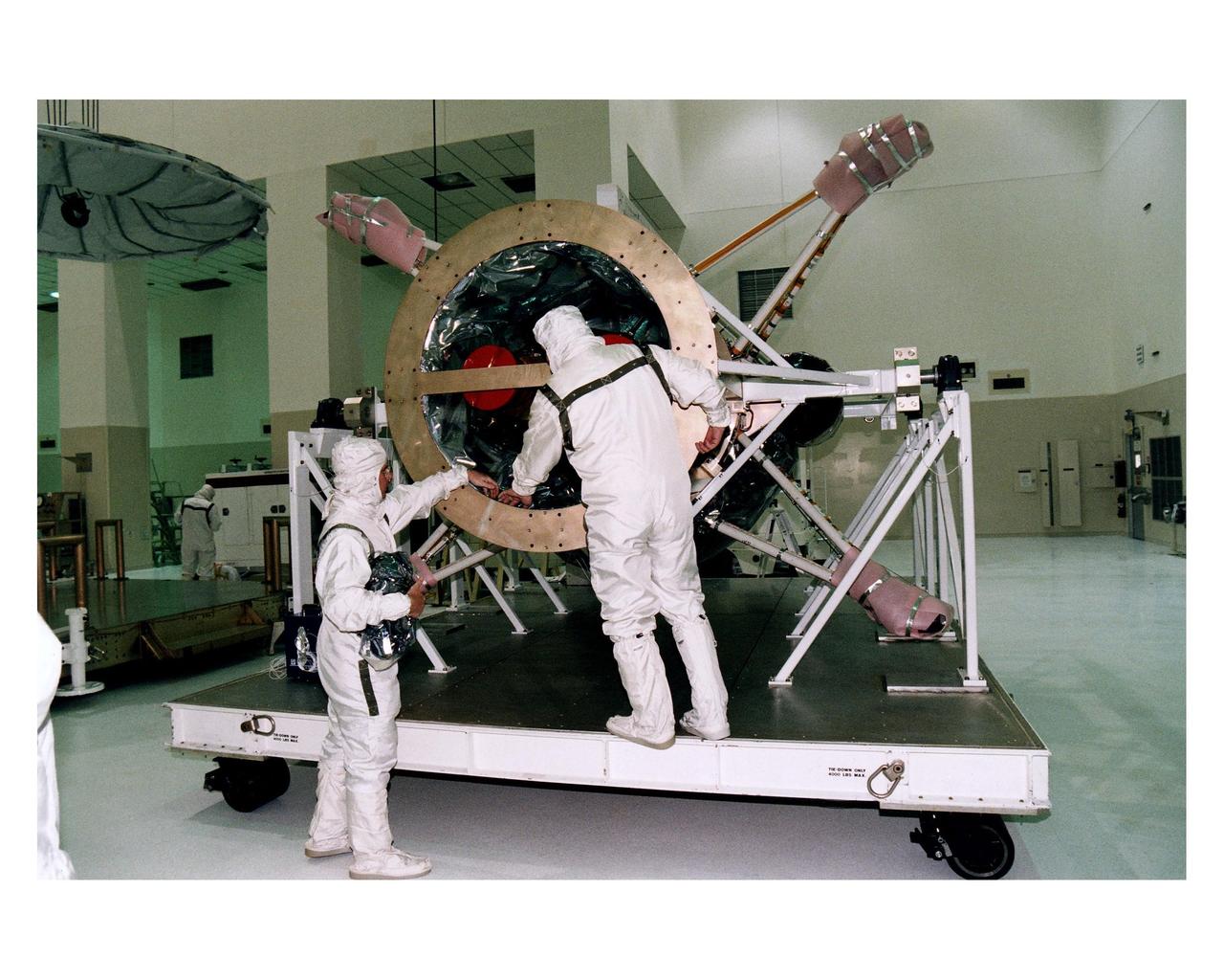
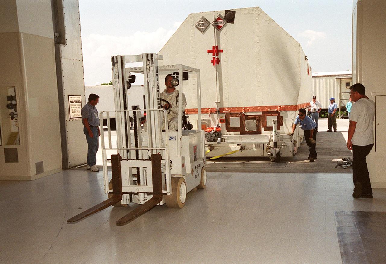
Workers take off the protective covering on the propulsion module for the Cassini spacecraft after uncrating the module at KSC's Spacecraft Assembly and Encapsulation Facility-2 (SAEF-2). The extended journey of 6.7 years to Saturn and the 4-year mission for Cassini once it gets there will require the spacecraft to carry a large amount of propellant for inflight trajectory-correction maneuvers and attitude control, particularly during the science observations. The propulsion module has redundant 445-newton main engines that burn nitrogen tetraoxide and monomethyl-hydrazine for main propulsion and 16 smaller 1-newton engines that burn hydrazine to control attitude and to correct small deviations from the spacecraft flight path. Cassini will be launched on a Titan IVB/Centaur expendable launch vehicle. Liftoff is targeted for October 6 from Launch Complex 40, Cape Canaveral Air Station

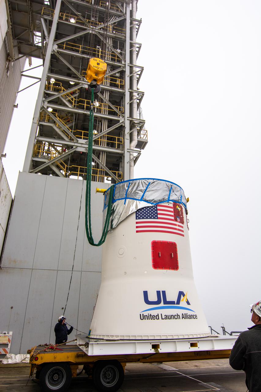
Technicians remove the United Launch Alliance (ULA) Atlas V boattail from its shipping container following its arrival at the Horizontal Integration Facility at Vandenberg Space Force Base in California on July 28, 2022, for NASA and the National Oceanic and Atmospheric Administration’s Joint Polar Satellite System-2 (JPSS-2) mission. The boattail is the connecting piece of flight hardware that joins the rocket’s upper Centaur stage with the payload fairing, which will house the JPSS-2 satellite. JPSS-2 is the third satellite in the Joint Polar Satellite System series and will scan the Earth as it orbits from the North to the South Pole, crossing the equator 14 times a day. Operating from 512 miles above Earth, JPSS-2 will capture data to improve weather forecasts, in turn helping scientists predict and prepare for extreme weather events and climate change. Launching as a secondary payload aboard the Atlas V is NASA’s Low-Earth Orbit Flight Test of an Inflatable Decelerator (LOFTID) – a demonstration of a cross-cutting aeroshell, or heat shield, for atmospheric re-entry. Dedicated to the memory of Bernard Kutter, LOFTID could be used for crewed and large robotic missions to Mars. Liftoff of the ULA Atlas V rocket is scheduled for Nov. 1, 2022, from Vandenberg’s Space Launch Complex-3E.

Technicians remove the United Launch Alliance (ULA) Atlas V boattail from its shipping container following its arrival at the Horizontal Integration Facility at Vandenberg Space Force Base in California on July 28, 2022, for NASA and the National Oceanic and Atmospheric Administration’s Joint Polar Satellite System-2 (JPSS-2) mission. The boattail is the connecting piece of flight hardware that joins the rocket’s upper Centaur stage with the payload fairing, which will house the JPSS-2 satellite. JPSS-2 is the third satellite in the Joint Polar Satellite System series and will scan the Earth as it orbits from the North to the South Pole, crossing the equator 14 times a day. Operating from 512 miles above Earth, JPSS-2 will capture data to improve weather forecasts, in turn helping scientists predict and prepare for extreme weather events and climate change. Launching as a secondary payload aboard the Atlas V is NASA’s Low-Earth Orbit Flight Test of an Inflatable Decelerator (LOFTID) – a demonstration of a cross-cutting aeroshell, or heat shield, for atmospheric re-entry. Dedicated to the memory of Bernard Kutter, LOFTID could be used for crewed and large robotic missions to Mars. Liftoff of the ULA Atlas V rocket is scheduled for Nov. 1, 2022, from Vandenberg’s Space Launch Complex-3E.

Like the Crab Nebula, the Vela Supernova Remnant has a radio pulsar at its center. In this image taken by the High Energy Astronomy Observatory (HEAO)-2/Einstein Observatory, the pulsar appears as a point source surrounded by weak and diffused emissions of x-rays. HEAO-2's computer processing system was able to record and display the total number of x-ray photons (a tiny bundle of radiant energy used as the fundamental unit of electromagnetic radiation) on a scale along the margin of the picture. The HEAO-2, the first imaging and largest x-ray telescope built to date, was capable of producing actual photographs of x-ray objects. Shortly after launch, the HEAO-2 was nicknamed the Einstein Observatory by its scientific experimenters in honor of the centernial of the birth of Albert Einstein, whose concepts of relativity and gravitation have influenced much of modern astrophysics, particularly x-ray astronomy. The HEAO-2, designed and developed by TRW, Inc. under the project management of the Marshall Space Flight Center, was launched aboard an Atlas/Centaur launch vehicle on November 13, 1978.

This image is an x-ray view of Eta Carinae Nebula showing bright stars taken with the High Energy Astronomy Observatory (HEAO)-2/Einstein Observatory. The Eta Carinae Nebula is a large and complex cloud of gas, crisscrossed with dark lanes of dust, some 6,500 light years from Earth. Buried deep in this cloud are many bright young stars and a very peculiar variable star. The HEAO-2, the first imaging and largest x-ray telescope built to date, was capable of producing actual photographs of x-ray objects. Shortly after launch, the HEAO-2 was nicknamed the Einstein Observatory by its scientific experimenters in honor of the centernial of the birth of Albert Einstein, whose concepts of relativity and gravitation have influenced much of modern astrophysics, particularly x-ray astronomy. The HEAO-2, designed and developed by TRW, Inc. under the project management of the Marshall Space Flight Center, was launched aboard an Atlas/Centaur launch vehicle on November 13, 1978.
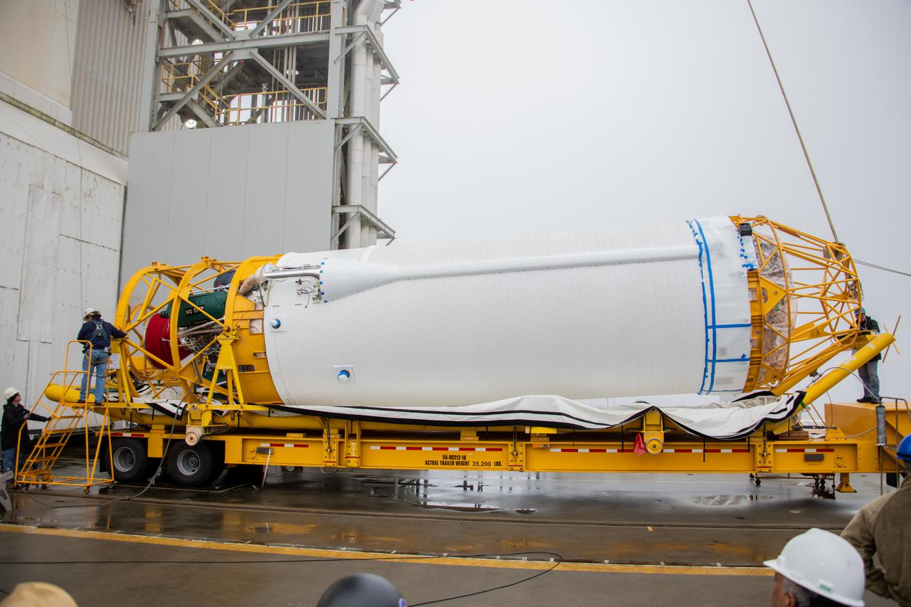
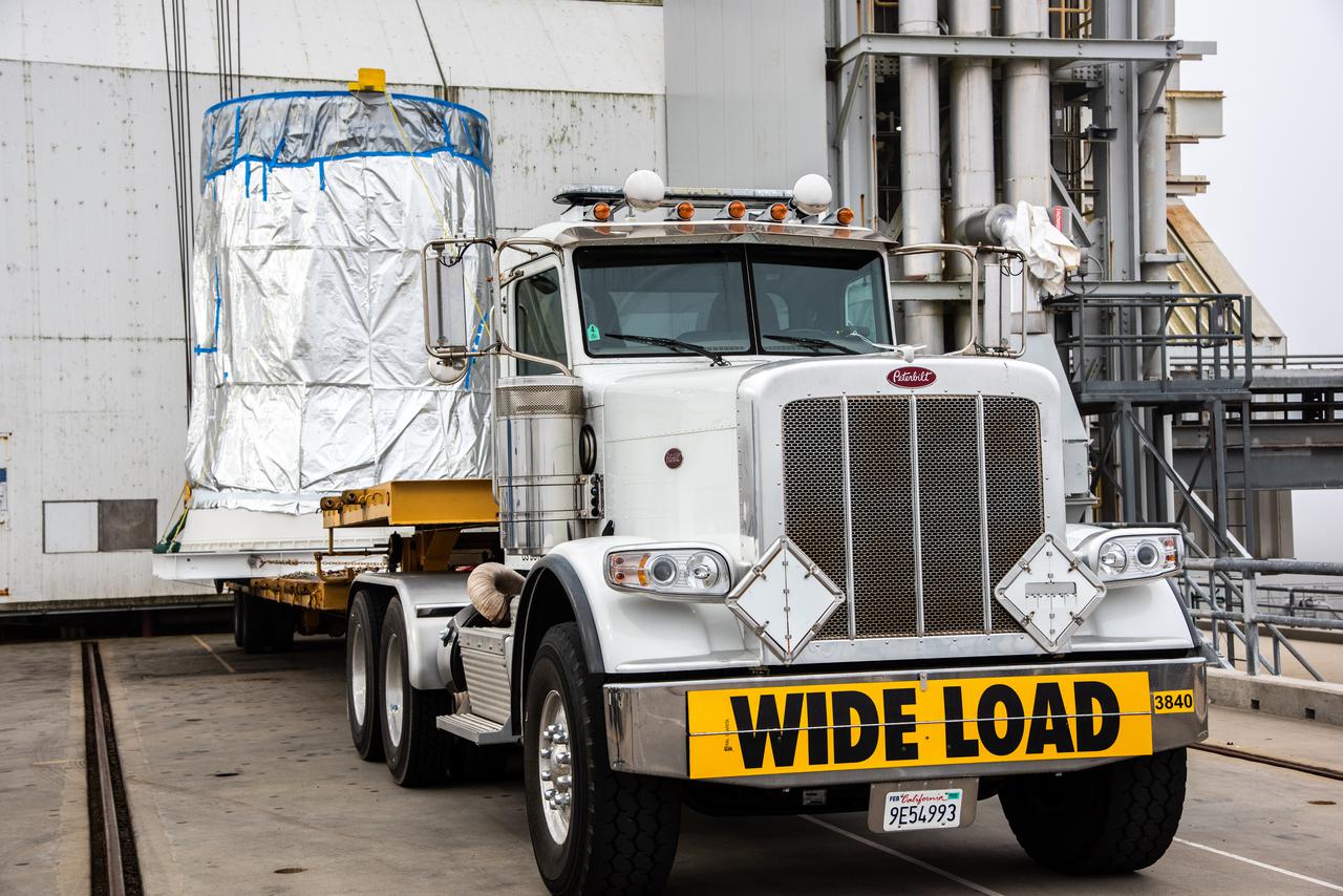
The interstage adapter (ISA) for the United Launch Alliance (ULA) Atlas V rocket that will launch NASA and the National Oceanic and Atmospheric Administration’s Joint Polar Satellite System-2 (JPSS-2) mission arrives at the Horizontal Integration Facility at Vandenberg Space Force Base in California on July 28, 2022. The ISA is the connecting piece of hardware between the Atlas V booster and the rocket’s Centaur upper stage. JPSS-2 is the third satellite in the Joint Polar Satellite System series and will scan the Earth as it orbits from the North to the South Pole, crossing the equator 14 times a day. Operating from 512 miles above Earth, JPSS-2 will capture data to improve weather forecasts, in turn helping scientists predict and prepare for extreme weather events and climate change. Launching as a secondary payload aboard the Atlas V is NASA’s Low-Earth Orbit Flight Test of an Inflatable Decelerator (LOFTID) – a demonstration of a cross-cutting aeroshell, or heat shield, for atmospheric re-entry. Dedicated to the memory of Bernard Kutter, LOFTID could be used for crewed and large robotic missions to Mars. Liftoff of the ULA Atlas V rocket is scheduled for Nov. 1, 2022, from Vandenberg’s Space Launch Complex-3E.
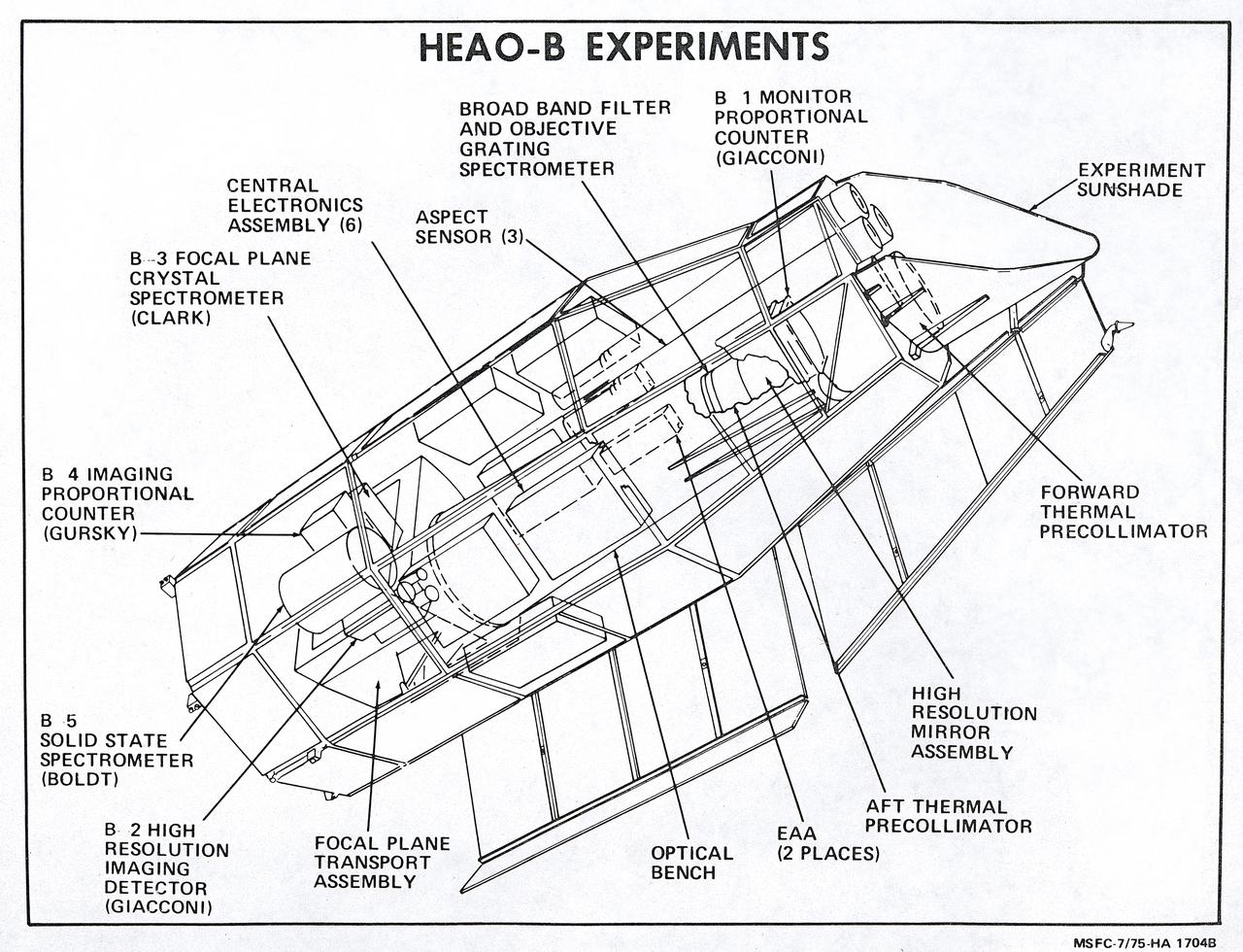
This illustration is a schematic of the High Energy Astronomy Observatory (HEAO)-2 and its experiments. It shows the focal plane instruments (at the right) plus the associated electronics for operating the telescope as it transmitted its observations to the ground. A fifth instrument, the Monitor Proportional Counter, is located near the front of the telescope. Four separate astronomical instruments are located at the focus of this telescope and they could be interchanged for different types of observations as the observatory pointed at interesting areas of the Sky. Two of these instruments produced images; a High Resolution Imaging Detector and an Imaging Proportional Counter. The other two instruments, the Solid State Spectrometer and the Crystal Spectrometer, measured the spectra of x-ray objects. A fifth instrument, the Monitor Proportional Counter, continuously viewed space independently to study a wider band of x-ray wavelengths and to examine the rapid time variations in the sources. The HEAO-2 was nicknamed the Einstein Observatory by its scientific experimenters in honor of the centernial of the birth of Albert Einstein, whose concepts of relativity and gravitation have influenced much of modern astrophysics, particularly x-ray astronomy. The HEAO-2, designed and developed by TRW, Inc. under the project management of the Marshall Space Flight Center, was launched aboard an Atlas/Centaur launch vehicle on November 13, 1978. The HEAO-2 was originally identified as HEAO-B but the designation was changed once the spacecraft achieved orbit.
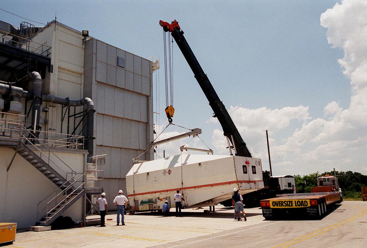
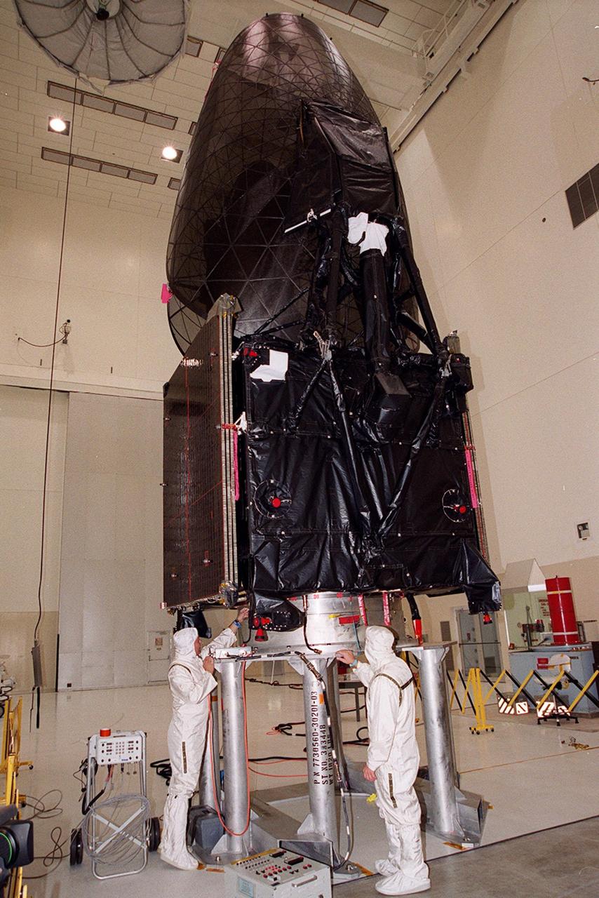
At the Spacecraft Assembly and Encapsulation Facility (SAEF-2), a crane lowers the crated Tracking and Data Relay Satellite (TDRS-H) onto the ground. It was transported to SAEF-2 on the truckbed at right. The TDRS will undergo testing in SAEF-2. One of three satellites (labeled H, I and J) being built in the Hughes Space and Communications Company Integrated Satellite Factory in El Segundo, Calif., the latest TDRS uses an innovative springback antenna design. A pair of 15-foot-diameter, flexible mesh antenna reflectors fold up for launch, then spring back into their original cupped circular shape on orbit. The new satellites will augment the TDRS system’s existing Sand Ku-band frequencies by adding Ka-band capability. TDRS will serve as the sole means of continuous, high-data-rate communication with the space shuttle, with the International Space Station upon its completion, and with dozens of unmanned scientific satellites in low earth orbit. The TDRS is scheduled to be launched from CCAFS June 29 aboard an Atlas IIA/Centaur rocket
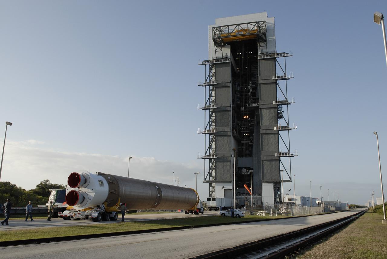
CAPE CANAVERAL, Fla. –– The Atlas V first stage is moved from the hangar at the Atlas Space Operations Facility. It is going to the Vertical Integration Facility near Cape Canaveral Air Force Station's Launch Complex 41. The Atlas V/Centaur is the launch vehicle for the Lunar Reconnaissance Orbiter, or LRO. The orbiter will carry seven instruments to provide scientists with detailed maps of the lunar surface and enhance our understanding of the moon's topography, lighting conditions, mineralogical composition and natural resources. Information gleaned from LRO will be used to select safe landing sites, determine locations for future lunar outposts and help mitigate radiation dangers to astronauts. Launch of LRO is targeted no earlier than June 2. Photo credit: NASA/Kim Shiflett
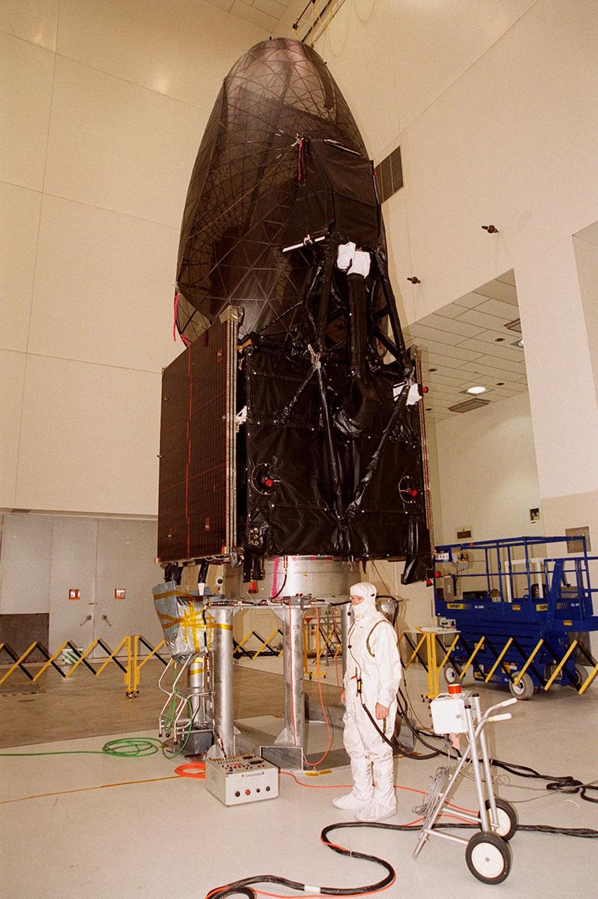
The Tracking and Data Relay Satellite (TDRS-H) sits on a workstand in KSC’s Spacecraft Assembly and Encapsulation Facility (SAEF-2) in order to undergo electrical testing. The TDRS is scheduled to be launched from CCAFS June 29 aboard an Atlas IIA/Centaur rocket. One of three satellites (labeled H, I and J) being built in the Hughes Space and Communications Company Integrated Satellite Factory in El Segundo, Calif., the latest TDRS uses an innovative springback antenna design. A pair of 15-foot-diameter, flexible mesh antenna reflectors fold up for launch, then spring back into their original cupped circular shape on orbit. The new satellites will augment the TDRS system’s existing Sand Ku-band frequencies by adding Ka-band capability. TDRS will serve as the sole means of continuous, high-data-rate communication with the space shuttle, with the International Space Station upon its completion, and with dozens of unmanned scientific satellites in low earth orbit
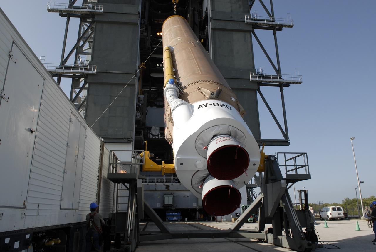
CAPE CANAVERAL, Fla. –– At the Vertical Integration Facility on Cape Canaveral Air Force Station's Launch Complex 41, the Atlas V first stage is being raised to a vertical position. The Atlas will be lifted into the VIF. The Atlas V/Centaur is the launch vehicle for the Lunar Reconnaissance Orbiter, or LRO. The orbiter will carry seven instruments to provide scientists with detailed maps of the lunar surface and enhance our understanding of the moon's topography, lighting conditions, mineralogical composition and natural resources. Information gleaned from LRO will be used to select safe landing sites, determine locations for future lunar outposts and help mitigate radiation dangers to astronauts. Launch of LRO is targeted no earlier than June 2. Photo credit: NASA/Kim Shiflett

Workers in KSC’s Spacecraft Assembly and Encapsulation Facility (SAEF-2) prepare the Tracking and Data Relay Satellite (TDRS-H) above them for electrical testing. The TDRS is scheduled to be launched from CCAFS June 29 aboard an Atlas IIA/Centaur rocket. One of three satellites (labeled H, I and J) being built in the Hughes Space and Communications Company Integrated Satellite Factory in El Segundo, Calif., the latest TDRS uses an innovative springback antenna design. A pair of 15-foot-diameter, flexible mesh antenna reflectors fold up for launch, then spring back into their original cupped circular shape on orbit. The new satellites will augment the TDRS system’s existing Sand Ku-band frequencies by adding Ka-band capability. TDRS will serve as the sole means of continuous, high-data-rate communication with the space shuttle, with the International Space Station upon its completion, and with dozens of unmanned scientific satellites in low earth orbit
CAPE CANAVERAL, Fla. –– The Atlas V first stage is being transferred from the hangar at the Atlas Space Operations Facility to the Vertical Integration Facility near Cape Canaveral Air Force Station's Launch Complex 41. The Atlas V/Centaur is the launch vehicle for the Lunar Reconnaissance Orbiter, or LRO. The orbiter will carry seven instruments to provide scientists with detailed maps of the lunar surface and enhance our understanding of the moon's topography, lighting conditions, mineralogical composition and natural resources. Information gleaned from LRO will be used to select safe landing sites, determine locations for future lunar outposts and help mitigate radiation dangers to astronauts. Launch of LRO is targeted no earlier than June 2. Photo credit: NASA/Kim Shiflett
At Launch Pad 36A, Cape Canaveral Air Station, a Centaur upper stage is mated to the lower stage Lockheed Martin Atlas IIA rocket. The rocket is scheduled to launch the NASA GOES-L satellite on May 15, at the opening of a launch window which extends from 2:23 to 4:41 a.m. EDT. Once in orbit, the satellite will become GOES-11, joining GOES-8, GOES-9 and GOES-10 in space. The fourth of a new advanced series of geostationary weather satellites for the National Oceanic and Atmospheric Administration (NOAA), GOES-L is a three-axis inertially stabilized spacecraft that will provide pictures and perform atmospheric sounding at the same time. Once launched, the satellite will undergo checkout and then provide backup capabilities for the existing, aging operational satellites

The Tracking and Data Relay Satellite (TDRS-H) sits on a workstand in KSC’s Spacecraft Assembly and Encapsulation Facility (SAEF-2) in order to undergo electrical testing. The TDRS is scheduled to be launched from CCAFS June 29 aboard an Atlas IIA/Centaur rocket. One of three satellites (labeled H, I and J) being built in the Hughes Space and Communications Company Integrated Satellite Factory in El Segundo, Calif., the latest TDRS uses an innovative springback antenna design. A pair of 15-foot-diameter, flexible mesh antenna reflectors fold up for launch, then spring back into their original cupped circular shape on orbit. The new satellites will augment the TDRS system’s existing Sand Ku-band frequencies by adding Ka-band capability. TDRS will serve as the sole means of continuous, high-data-rate communication with the space shuttle, with the International Space Station upon its completion, and with dozens of unmanned scientific satellites in low earth orbit
Workers in KSC’s Spacecraft Assembly and Encapsulation Facility (SAEF-2) conduct electrical testing on the Tracking and Data Relay Satellite (TDRS-H) above them. The TDRS is scheduled to be launched from CCAFS June 29 aboard an Atlas IIA/Centaur rocket. One of three satellites (labeled H, I and J) being built in the Hughes Space and Communications Company Integrated Satellite Factory in El Segundo, Calif., the latest TDRS uses an innovative springback antenna design. A pair of 15-foot-diameter, flexible mesh antenna reflectors fold up for launch, then spring back into their original cupped circular shape on orbit. The new satellites will augment the TDRS system’s existing Sand Ku-band frequencies by adding Ka-band capability. TDRS will serve as the sole means of continuous, high-data-rate communication with the space shuttle, with the International Space Station upon its completion, and with dozens of unmanned scientific satellites in low earth orbit
CAPE CANAVERAL, Fla. –– At the Vertical Integration Facility on Cape Canaveral Air Force Station's Launch Complex 41, cranes are attached to the Atlas V first stage to raise it to vertical. The Atlas will be lifted into the VIF. The Atlas V/Centaur is the launch vehicle for the Lunar Reconnaissance Orbiter, or LRO. The orbiter will carry seven instruments to provide scientists with detailed maps of the lunar surface and enhance our understanding of the moon's topography, lighting conditions, mineralogical composition and natural resources. Information gleaned from LRO will be used to select safe landing sites, determine locations for future lunar outposts and help mitigate radiation dangers to astronauts. Launch of LRO is targeted no earlier than June 2. Photo credit: NASA/Kim Shiflett
CAPE CANAVERAL, Fla. –– At the Vertical Integration Facility on Cape Canaveral Air Force Station's Launch Complex 41, the Atlas V first stage is being raised to a vertical position. The Atlas will be lifted into the VIF. The Atlas V/Centaur is the launch vehicle for the Lunar Reconnaissance Orbiter, or LRO. The orbiter will carry seven instruments to provide scientists with detailed maps of the lunar surface and enhance our understanding of the moon's topography, lighting conditions, mineralogical composition and natural resources. Information gleaned from LRO will be used to select safe landing sites, determine locations for future lunar outposts and help mitigate radiation dangers to astronauts. Launch of LRO is targeted no earlier than June 2. Photo credit: NASA/Kim Shiflett
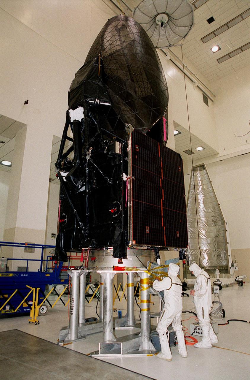
Workers in KSC’s Spacecraft Assembly and Encapsulation Facility (SAEF-2) prepare the Tracking and Data Relay Satellite (TDRS-H) above them for electrical testing. The TDRS is scheduled to be launched from CCAFS June 29 aboard an Atlas IIA/Centaur rocket. One of three satellites (labeled H, I and J) being built in the Hughes Space and Communications Company Integrated Satellite Factory in El Segundo, Calif., the latest TDRS uses an innovative springback antenna design. A pair of 15-foot-diameter, flexible mesh antenna reflectors fold up for launch, then spring back into their original cupped circular shape on orbit. The new satellites will augment the TDRS system’s existing Sand Ku-band frequencies by adding Ka-band capability. TDRS will serve as the sole means of continuous, high-data-rate communication with the space shuttle, with the International Space Station upon its completion, and with dozens of unmanned scientific satellites in low earth orbit
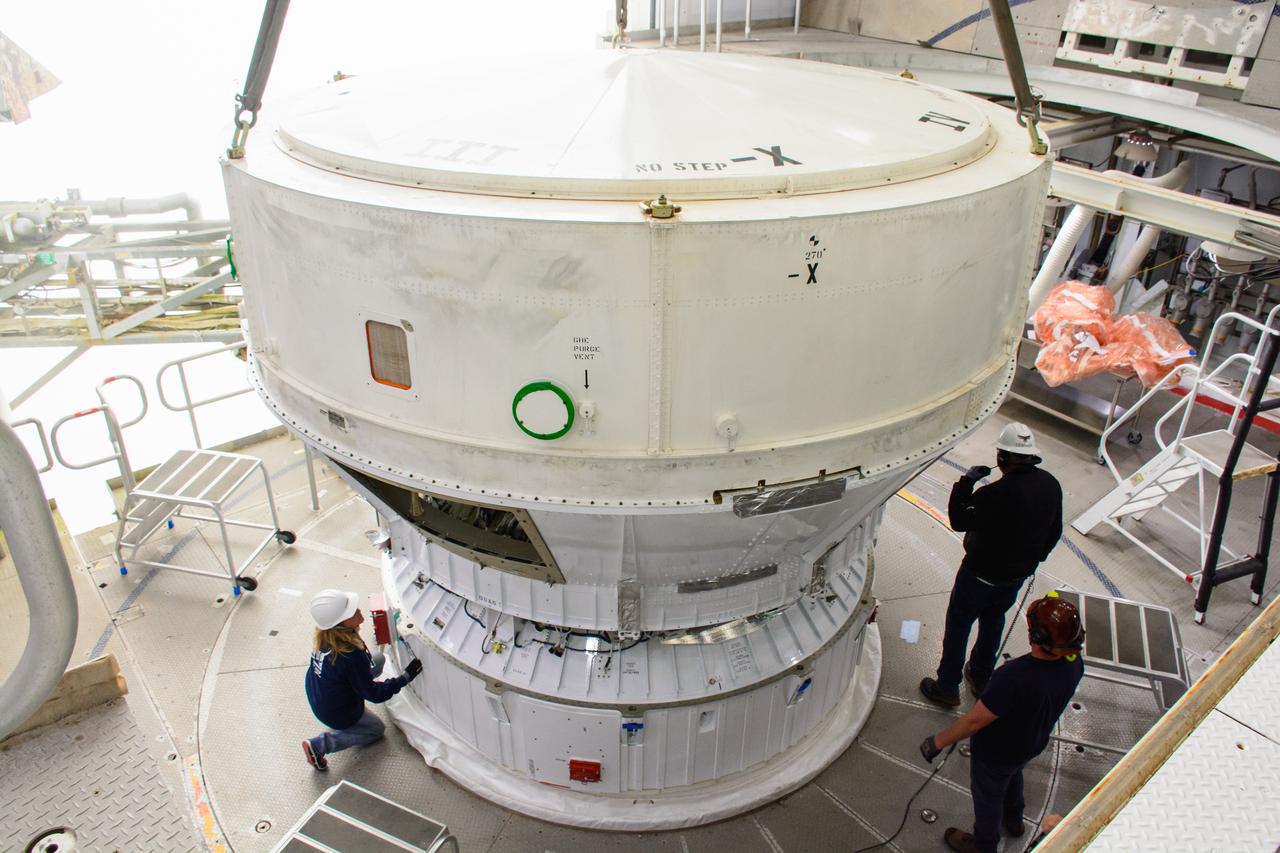
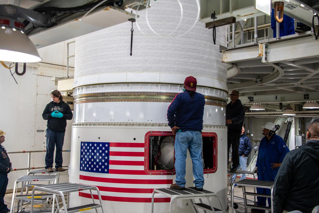
Inside the Vertical Integration Facility (VIF) at Vandenberg Space Force Base in California, technicians secure the United Launch Alliance (ULA) Atlas V boattail onto the rocket’s Centaur upper stage on Oct. 4, 2022, for the National Oceanic and Atmospheric Administration’s (NOAA) and NASA’s Joint Polar Satellite System-2 (JPSS-2) mission. The boattail is the connecting piece of flight hardware that joins that Atlas V upper stage with the payload fairing – the protective casing surrounding the JPSS-2 satellite. Once the payload fairing arrives at the VIF, teams will lower it onto the boattail to complete the Atlas V stack. JPSS-2 is the third satellite in the Joint Polar Satellite System series and will scan the Earth as it orbits from the North to the South Pole, crossing the equator 14 times a day. Operating from 512 miles above Earth, JPSS-2 will capture data to improve weather forecasts, in turn helping scientists predict and prepare for extreme weather events and climate change. Launching as a secondary payload to JPSS-2 is NASA’s Low-Earth Orbit Flight Test of an Inflatable Decelerator (LOFTID), dedicated to the memory of Bernard Kutter. LOFTID is a technology demonstration of an inflatable heat shield that could one day help land humans on Mars. Liftoff is targeted for 2:25 a.m. Pacific time (5:25 a.m. Eastern time) on Nov. 1, 2022, from Vandenberg’s Space Launch Complex-3E.
Inside the Vertical Integration Facility (VIF) at Vandenberg Space Force Base in California, technicians monitor the United Launch Alliance (ULA) Atlas V boattail as it’s lowered by crane onto the rocket’s Centaur upper stage on Oct. 4, 2022, for the National Oceanic and Atmospheric Administration’s (NOAA) and NASA’s Joint Polar Satellite System-2 (JPSS-2) mission. The boattail is the connecting piece of flight hardware that joins that Atlas V upper stage with the payload fairing – the protective casing surrounding the JPSS-2 satellite. Once the payload fairing arrives at the VIF, teams will lower it onto the boattail to complete the Atlas V stack. JPSS-2 is the third satellite in the Joint Polar Satellite System series and will scan the Earth as it orbits from the North to the South Pole, crossing the equator 14 times a day. Operating from 512 miles above Earth, JPSS-2 will capture data to improve weather forecasts, in turn helping scientists predict and prepare for extreme weather events and climate change. Launching as a secondary payload to JPSS-2 is NASA’s Low-Earth Orbit Flight Test of an Inflatable Decelerator (LOFTID), dedicated to the memory of Bernard Kutter. LOFTID is a technology demonstration of an inflatable heat shield that could one day help land humans on Mars. Liftoff is targeted for 2:25 a.m. Pacific time (5:25 a.m. Eastern time) on Nov. 1, 2022, from Vandenberg’s Space Launch Complex-3E.
Technicians lower the United Launch Alliance (ULA) Atlas V boattail onto the rocket’s Centaur upper stage inside the Vertical Integration Facility at Vandenberg Space Force Base in California on Oct. 4, 2022, for the National Oceanic and Atmospheric Administration’s (NOAA) and NASA’s Joint Polar Satellite System-2 (JPSS-2) mission. The boattail is the connecting piece of flight hardware that joins that Atlas V upper stage with the payload fairing – the protective casing surrounding the JPSS-2 satellite. Once the payload fairing arrives at the VIF, teams will lower it onto the boattail to complete the Atlas V stack. JPSS-2 is the third satellite in the Joint Polar Satellite System series and will scan the Earth as it orbits from the North to the South Pole, crossing the equator 14 times a day. Operating from 512 miles above Earth, JPSS-2 will capture data to improve weather forecasts, in turn helping scientists predict and prepare for extreme weather events and climate change. Launching as a secondary payload to JPSS-2 is NASA’s Low-Earth Orbit Flight Test of an Inflatable Decelerator (LOFTID), dedicated to the memory of Bernard Kutter. LOFTID is a technology demonstration of an inflatable heat shield that could one day help land humans on Mars. Liftoff is targeted for 2:25 a.m. Pacific time (5:25 a.m. Eastern time) on Nov. 1, 2022, from Vandenberg’s Space Launch Complex-3E.
Inside the Vertical Integration Facility at Space Launch Complex 3 at Vandenberg Space Force Base in California, United Launch Alliance workers assist as the Centaur second stage for NASA’s Landsat 9 mission is lowered onto the Atlas V booster on July 15, 2021. The Landsat 9 mission will launch atop the Atlas V rocket from Vandenberg in September 2021. The launch is being managed by NASA’s Launch Services Program based at Kennedy Space Center, America’s multiuser spaceport. The Landsat 9 satellite will continue the nearly 50-year legacy of previous Landsat missions. It will monitor key natural and economic resources from orbit. Landsat 9 is managed by the agency’s Goddard Space Flight Center in Greenbelt, Maryland. The satellite will carry two instruments: the Operational Land Imager 2, which collects images of Earth’s landscapes in visible, near infrared and shortwave infrared light, and the Thermal Infrared Sensor 2, which measures the temperature of land surfaces. Like its predecessors, Landsat 9 is a joint mission between NASA and the U.S. Geological Survey.
The crated Tracking and Data Relay Satellite (TDRS-H) is pulled inside the Spacecraft Assembly and Encapsulation Facility (SAEF-2) after its arrival at KSC. The TDRS will undergo testing in the SAEF-2. One of three satellites (labeled H, I and J) being built in the Hughes Space and Communications Company Integrated Satellite Factory in El Segundo, Calif., the latest TDRS uses an innovative springback antenna design. A pair of 15-foot-diameter, flexible mesh antenna reflectors fold up for launch, then spring back into their original cupped circular shape on orbit. The new satellites will augment the TDRS system’s existing Sand Ku-band frequencies by adding Ka-band capability. TDRS will serve as the sole means of continuous, high-data-rate communication with the space shuttle, with the International Space Station upon its completion, and with dozens of unmanned scientific satellites in low earth orbit. The TDRS is scheduled to be launched from CCAFS June 29 aboard an Atlas IIA/Centaur rocket
Inside the Vertical Integration Facility at Space Launch Complex 3 at Vandenberg Space Source Base in California, workers help secure the interstage and assembly second stage adapters to the Centaur second stage of the United Launch Alliance Atlas V rocket for NASA’s Landsat 9 mission on July 14, 2021. Landsat 9 will launch atop the Atlas V rocket from Vandenberg in September 2021. The launch is being managed by NASA’s Launch Services Program based at Kennedy Space Center, America’s multiuser spaceport. The Landsat 9 satellite will continue the nearly 50-year legacy of previous Landsat missions. It will monitor key natural and economic resources from orbit. Landsat 9 is managed by the agency’s Goddard Space Flight Center in Greenbelt, Maryland. The satellite will carry two instruments: the Operational Land Imager 2, which collects images of Earth’s landscapes in visible, near infrared and shortwave infrared light, and the Thermal Infrared Sensor 2, which measures the temperature of land surfaces. Like its predecessors, Landsat 9 is a joint mission between NASA and the U.S. Geological Survey.
Inside the Vertical Integration Facility at Space Launch Complex 3 at Vandenberg Space Source Base in California, workers help secure the interstage and assembly second stage adapters to the Centaur second stage of the United Launch Alliance Atlas V rocket for NASA’s Landsat 9 mission on July 14, 2021. Landsat 9 will launch atop the Atlas V rocket from Vandenberg in September 2021. The launch is being managed by NASA’s Launch Services Program based at Kennedy Space Center, America’s multiuser spaceport. The Landsat 9 satellite will continue the nearly 50-year legacy of previous Landsat missions. It will monitor key natural and economic resources from orbit. Landsat 9 is managed by the agency’s Goddard Space Flight Center in Greenbelt, Maryland. The satellite will carry two instruments: the Operational Land Imager 2, which collects images of Earth’s landscapes in visible, near infrared and shortwave infrared light, and the Thermal Infrared Sensor 2, which measures the temperature of land surfaces. Like its predecessors, Landsat 9 is a joint mission between NASA and the U.S. Geological Survey.

The crated Tracking and Data Relay Satellite (TDRS-H) is pulled inside the Spacecraft Assembly and Encapsulation Facility (SAEF-2) after its arrival at KSC. The TDRS will undergo testing in the SAEF-2. One of three satellites (labeled H, I and J) being built in the Hughes Space and Communications Company Integrated Satellite Factory in El Segundo, Calif., the latest TDRS uses an innovative springback antenna design. A pair of 15-foot-diameter, flexible mesh antenna reflectors fold up for launch, then spring back into their original cupped circular shape on orbit. The new satellites will augment the TDRS system’s existing Sand Ku-band frequencies by adding Ka-band capability. TDRS will serve as the sole means of continuous, high-data-rate communication with the space shuttle, with the International Space Station upon its completion, and with dozens of unmanned scientific satellites in low earth orbit. The TDRS is scheduled to be launched from CCAFS June 29 aboard an Atlas IIA/Centaur rocket
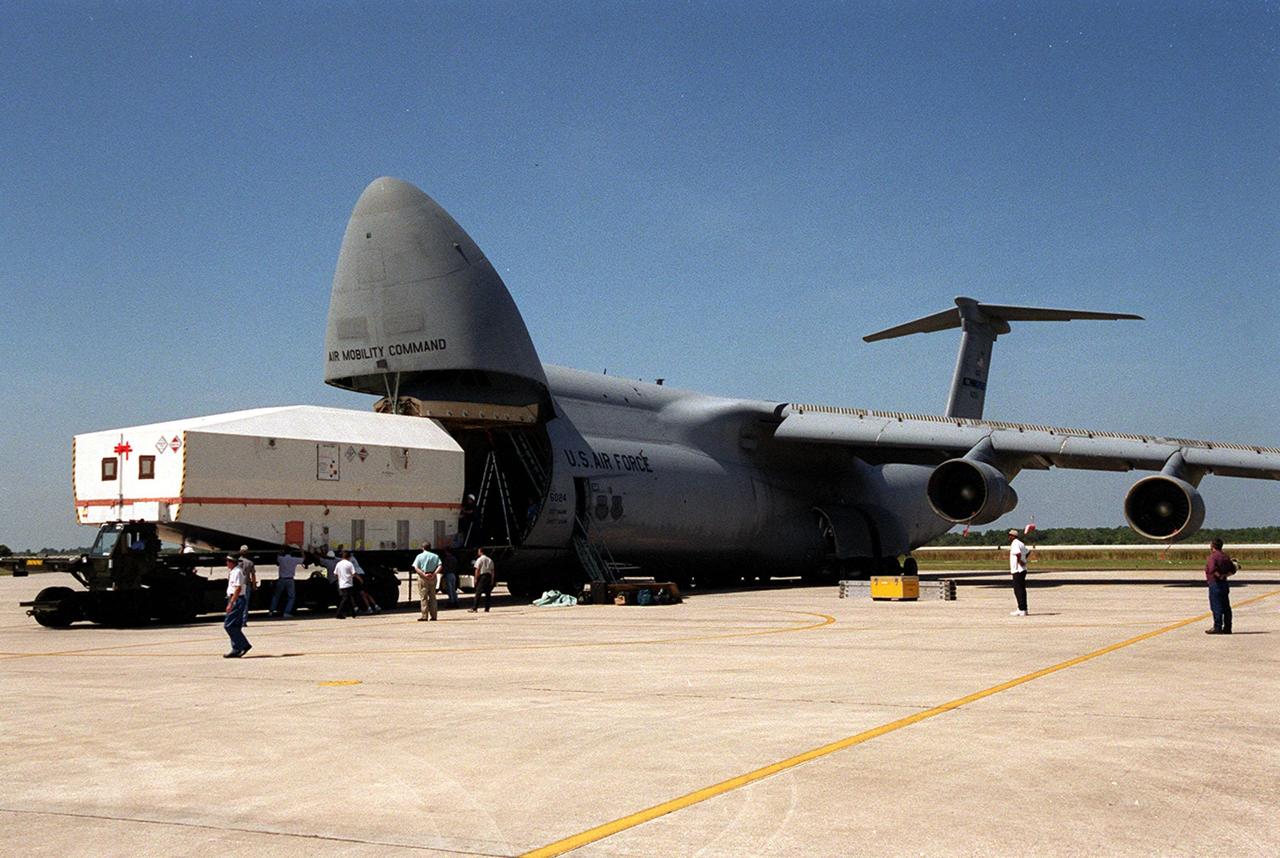
At the Shuttle Landing Facility, the crated Tracking and Data Relay Satellite (TDRS-H) is offloaded from an air cargo plane. It will be taken to the Spacecraft Assembly and Encapsulation Facility (SAEF-2) for testing. The TDRS is one of three (labeled H, I and J) being built in the Hughes Space and Communications Company Integrated Satellite Factory in El Segundo, Calif. The latest TDRS uses an innovative springback antenna design. A pair of 15-foot-diameter, flexible mesh antenna reflectors fold up for launch, then spring back into their original cupped circular shape on orbit. The new satellites will augment the TDRS system’s existing Sand Ku-band frequencies by adding Ka-band capability. TDRS will serve as the sole means of continuous, high-data-rate communication with the space shuttle, with the International Space Station upon its completion, and with dozens of unmanned scientific satellites in low earth orbit. The TDRS is scheduled to be launched from CCAFS June 29 aboard an Atlas IIA/Centaur rocket

After its arrival at the Shuttle Landing Facility, the crated Tracking and Data Relay Satellite (TDRS-H) is transported past the Vehicle Assembly Building (in the background) to the Spacecraft Assembly and Encapsulation Facility (SAEF-2) for testing. The TDRS is one of three (labeled H, I and J) being built in the Hughes Space and Communications Company Integrated Satellite Factory in El Segundo, Calif. The latest TDRS uses an innovative springback antenna design. A pair of 15-foot-diameter, flexible mesh antenna reflectors fold up for launch, then spring back into their original cupped circular shape on orbit. The new satellites will augment the TDRS system’s existing Sand Ku-band frequencies by adding Ka-band capability. TDRS will serve as the sole means of continuous, high-data-rate communication with the space shuttle, with the International Space Station upon its completion, and with dozens of unmanned scientific satellites in low earth orbit. The TDRS is scheduled to be launched from CCAFS June 29 aboard an Atlas IIA/Centaur rocket

The logo for the Tracking and Data Relay Satellite (TDRS-H) is predominantly displayed on the fairing that will encapsulate the satellite for launch. The fairing is in KSC’s Spacecraft Assembly and Encapsulation Facility (SAEF-2) where TDRS is undergoing testing. The TDRS is scheduled to be launched from CCAFS June 29 aboard an Atlas IIA/Centaur rocket. One of three satellites (labeled H, I and J) being built in the Hughes Space and Communications Company Integrated Satellite Factory in El Segundo, Calif., the latest TDRS uses an innovative springback antenna design. A pair of 15-foot-diameter, flexible mesh antenna reflectors fold up for launch, then spring back into their original cupped circular shape on orbit. The new satellites will augment the TDRS system’s existing Sand Ku-band frequencies by adding Ka-band capability. TDRS will serve as the sole means of continuous, high-data-rate communication with the space shuttle, with the International Space Station upon its completion, and with dozens of unmanned scientific satellites in low earth orbit
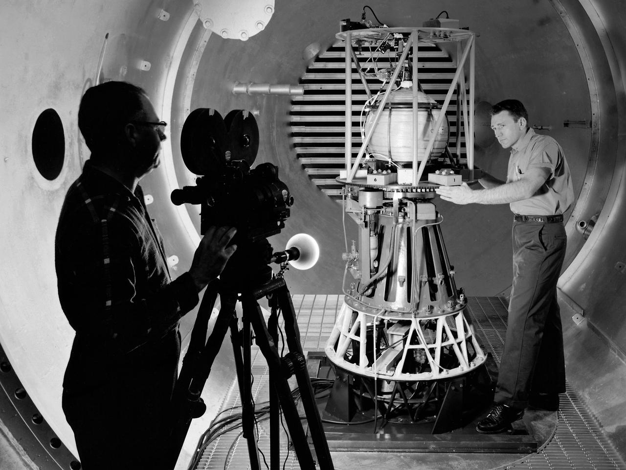
Mechanic Howard Wine inspects the setup of a spin isolator in Cell 2 of the Propulsion Systems Laboratory at the National Aeronautics and Space Administration (NASA) Lewis Research Center. Photographer Al Jecko filmed the proceedings. This test was unique in that the chamber’s altitude system was used, but not its inlet air flow. The test was in preparation for an upcoming launch of modified liquid hydrogen propellant tank on a sounding rocket. This Weightlessness Analysis Sounding Probe (WASP) was part of Lewis investigation into methods for controlling partially filled liquid hydrogen fuel tanks during flight. Second-stage rockets, the Centaur in particular, were designed to stop their engines and coast, then restart them when needed. During this coast period, the propellant often shifted inside the tank. This movement could throw the rocket off course or result in the sloshing of fuel away from the fuel pump. Wine was one of only three journeymen mechanics at Lewis when he was hired in January 1954. He spent his first decade in the Propulsion Systems Laboratory and was soon named a section head. Wine went on to serve as Assistant Division Chief and later served as an assistant to the director. Jecko joined the center in 1947 as a photographer and artist. He studied at the Cleveland School or Art and was known for his cartoon drawing. He worked at the center for 26 years.
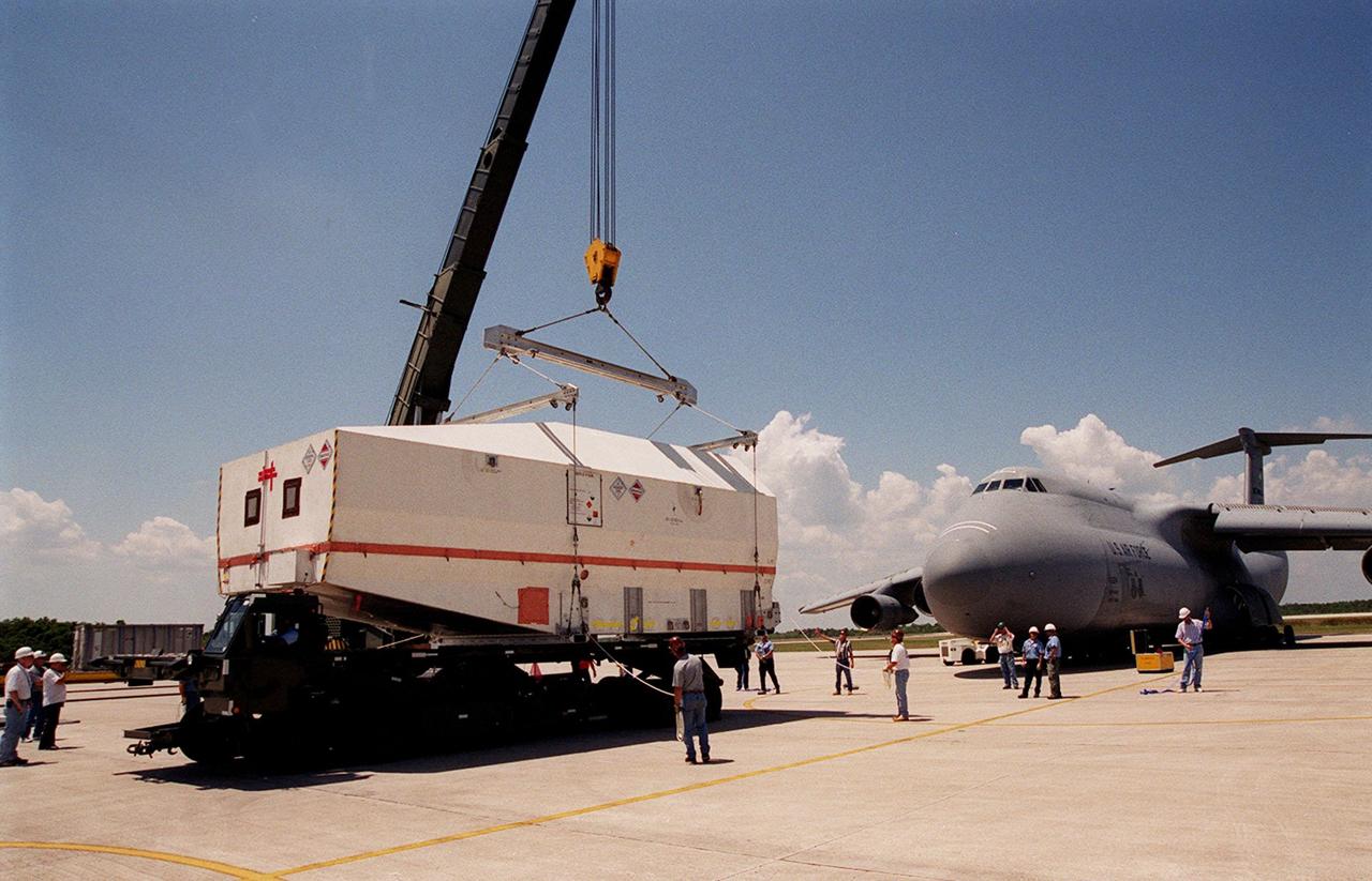
At the Shuttle Landing Facility, the crated Tracking and Data Relay Satellite (TDRS-H) is placed onto a transporter for its move to the Spacecraft Assembly and Encapsulation Facility (SAEF-2) for testing. The TDRS is one of three (labeled H, I and J) being built in the Hughes Space and Communications Company Integrated Satellite Factory in El Segundo, Calif. The latest TDRS uses an innovative springback antenna design. A pair of 15-foot-diameter, flexible mesh antenna reflectors fold up for launch, then spring back into their original cupped circular shape on orbit. The new satellites will augment the TDRS system’s existing Sand Ku-band frequencies by adding Ka-band capability. TDRS will serve as the sole means of continuous, high-data-rate communication with the space shuttle, with the International Space Station upon its completion, and with dozens of unmanned scientific satellites in low earth orbit. The TDRS is scheduled to be launched from CCAFS June 29 aboard an Atlas IIA/Centaur rocket
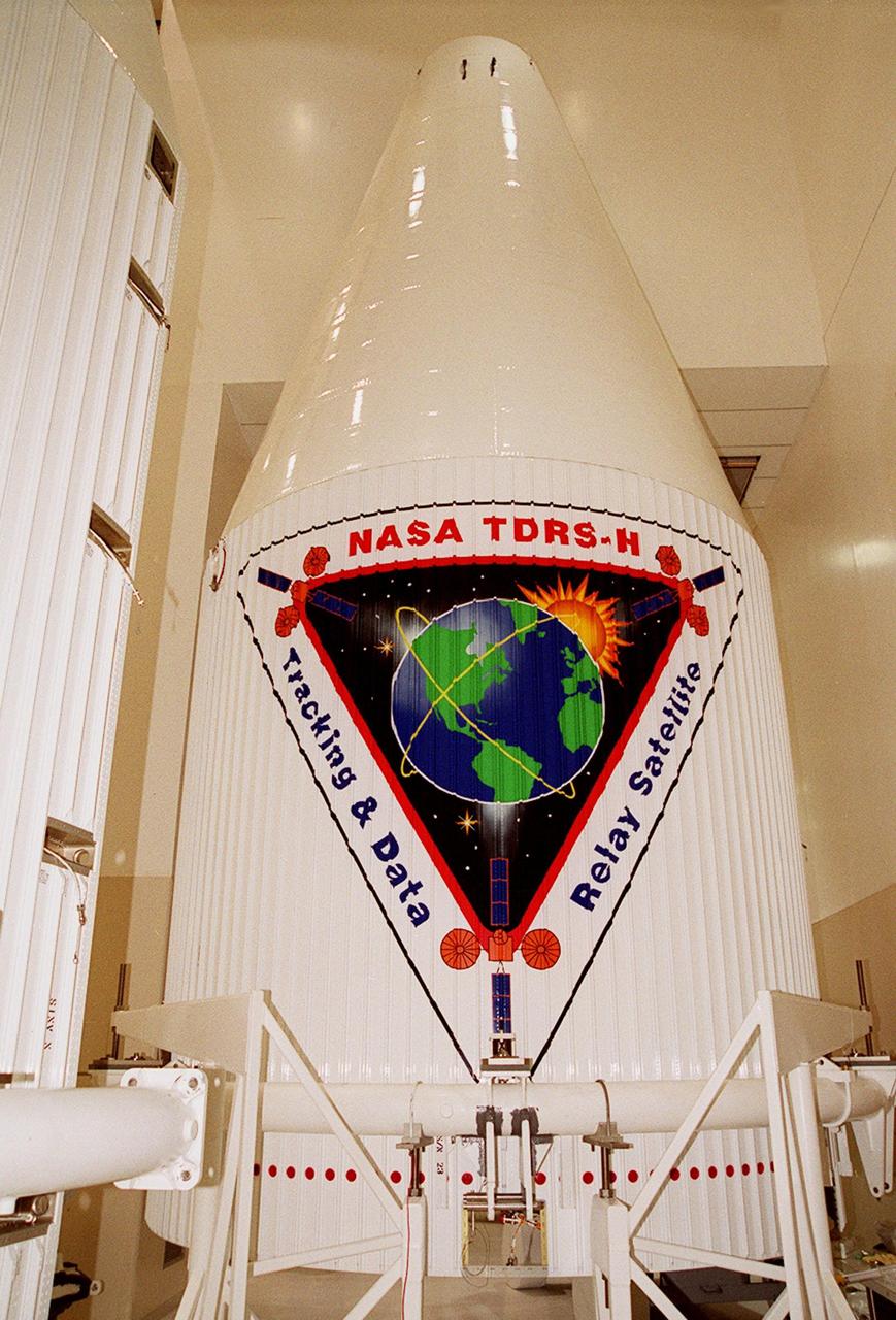
The logo for the Tracking and Data Relay Satellite (TDRS-H) is predominantly displayed on the fairing that will encapsulate the satellite for launch. The fairing is in KSC’s Spacecraft Assembly and Encapsulation Facility (SAEF-2) where TDRS is undergoing testing. The TDRS is scheduled to be launched from CCAFS June 29 aboard an Atlas IIA/Centaur rocket. One of three satellites (labeled H, I and J) being built in the Hughes Space and Communications Company Integrated Satellite Factory in El Segundo, Calif., the latest TDRS uses an innovative springback antenna design. A pair of 15-foot-diameter, flexible mesh antenna reflectors fold up for launch, then spring back into their original cupped circular shape on orbit. The new satellites will augment the TDRS system’s existing Sand Ku-band frequencies by adding Ka-band capability. TDRS will serve as the sole means of continuous, high-data-rate communication with the space shuttle, with the International Space Station upon its completion, and with dozens of unmanned scientific satellites in low earth orbit
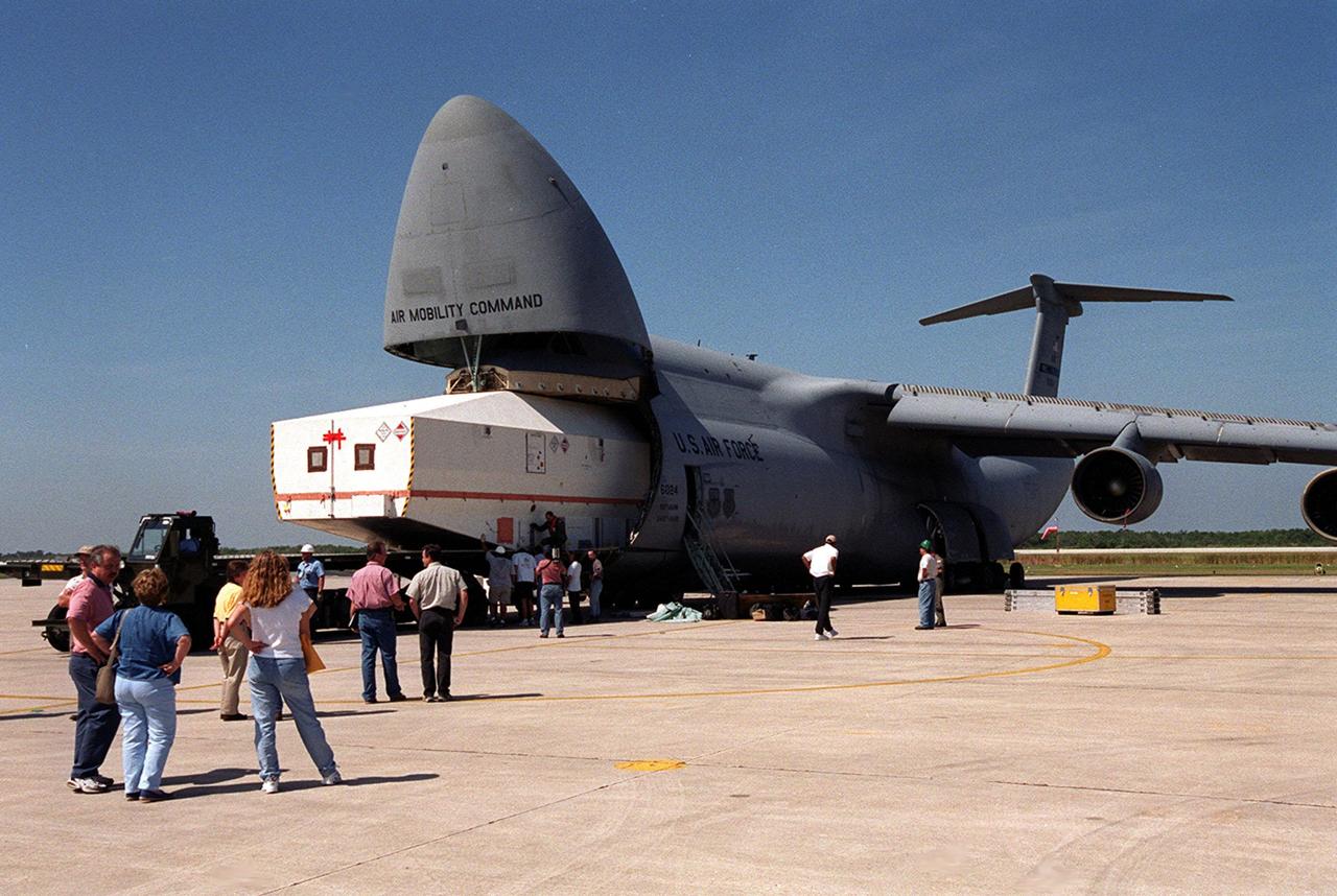
At the Shuttle Landing Facility, the crated Tracking and Data Relay Satellite (TDRS-H) is offloaded from an air cargo plane. It will be taken to the Spacecraft Assembly and Encapsulation Facility (SAEF-2) for testing. The TDRS is one of three (labeled H, I and J) being built in the Hughes Space and Communications Company Integrated Satellite Factory in El Segundo, Calif. The latest TDRS uses an innovative springback antenna design. A pair of 15-foot-diameter, flexible mesh antenna reflectors fold up for launch, then spring back into their original cupped circular shape on orbit. The new satellites will augment the TDRS system’s existing Sand Ku-band frequencies by adding Ka-band capability. TDRS will serve as the sole means of continuous, high-data-rate communication with the space shuttle, with the International Space Station upon its completion, and with dozens of unmanned scientific satellites in low earth orbit. The TDRS is scheduled to be launched from CCAFS June 29 aboard an Atlas IIA/Centaur rocket
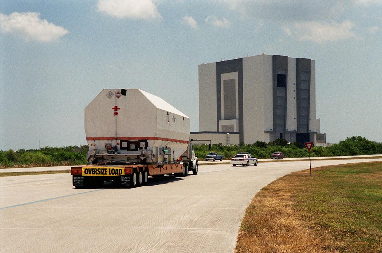
After its arrival at the Shuttle Landing Facility, the crated Tracking and Data Relay Satellite (TDRS-H) is transported past the Vehicle Assembly Building (in the background) to the Spacecraft Assembly and Encapsulation Facility (SAEF-2) for testing. The TDRS is one of three (labeled H, I and J) being built in the Hughes Space and Communications Company Integrated Satellite Factory in El Segundo, Calif. The latest TDRS uses an innovative springback antenna design. A pair of 15-foot-diameter, flexible mesh antenna reflectors fold up for launch, then spring back into their original cupped circular shape on orbit. The new satellites will augment the TDRS system’s existing Sand Ku-band frequencies by adding Ka-band capability. TDRS will serve as the sole means of continuous, high-data-rate communication with the space shuttle, with the International Space Station upon its completion, and with dozens of unmanned scientific satellites in low earth orbit. The TDRS is scheduled to be launched from CCAFS June 29 aboard an Atlas IIA/Centaur rocket
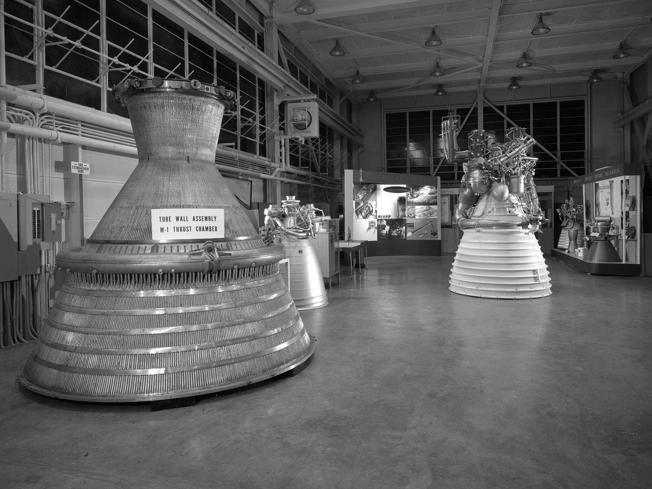
An array of rocket engines displayed in the Propulsion Systems Laboratory for the 1966 Inspection held at the National Aeronautics and Space Administration (NASA) Lewis Research Center. Lewis engineers had been working on chemical, nuclear, and solid rocket engines throughout the 1960s. The engines on display are from left to right: two scale models of the Aerojet M-1, a Rocketdyne J-2, a Pratt and Whitney RL-10, and a Rocketdyne throttleable engine. Also on display are several ejector plates and nozzles. The Chemical Rocket Division resolved issues such as combustion instability and screech, and improved operation of cooling systems and turbopumps. The 1.5-million pound thrust M-1 engine was the largest hydrogen-fueled rocket engine ever created. It was a joint project between NASA Lewis and Aerojet-General. Although much larger in size, the M-1 used technology developed for the RL-10 and J-2. The M-1 program was cancelled in late 1965 due to budget cuts and the lack of a post-Apollo mission. The October 1966 Inspection was the culmination of almost a year of events held to mark the centers’ 25th anniversary. The three‐day Inspection, Lewis’ first since 1957, drew 2000 business, industry, and government executives and included an employee open house. The visitors witnessed presentations at the major facilities and viewed the Gemini VII spacecraft, a Centaur rocket, and other displays in the hangar. In addition, Lewis’ newest facility, the Zero Gravity Facility, was shown off for the first time.
Test engineers monitor an engine firing from the control room of the Rocket Engine Test Facility at the National Advisory Committee for Aeronautics (NACA) Lewis Flight Propulsion Laboratory. The Rocket Engine Test Facility, built in the early 1950s, had a rocket stand designed to evaluate high-energy propellants and rocket engine designs. The facility was used to study numerous different types of rocket engines including the Pratt and Whitney RL-10 engine for the Centaur rocket and Rocketdyne’s F-1 and J-2 engines for the Saturn rockets. The Rocket Engine Test Facility was built in a ravine at the far end of the laboratory because of its use of the dangerous propellants such as liquid hydrogen and liquid fluorine. The control room was located in a building 1,600 feet north of the test stand to protect the engineers running the tests. The main control and instrument consoles were centrally located in the control room and surrounded by boards controlling and monitoring the major valves, pumps, motors, and actuators. A camera system at the test stand allowed the operators to view the tests, but the researchers were reliant on data recording equipment, sensors, and other devices to provide test data. The facility’s control room was upgraded several times over the years. Programmable logic controllers replaced the electro-mechanical control devices. The new controllers were programed to operate the valves and actuators controlling the fuel, oxidant, and ignition sequence according to a predetermined time schedule.
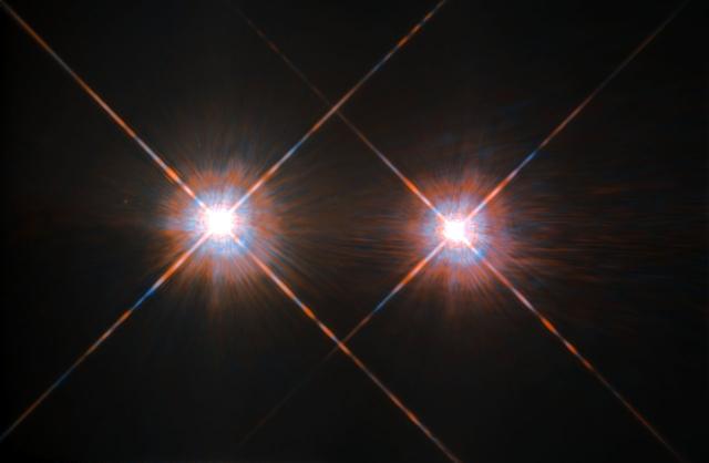
The closest star system to the Earth is the famous Alpha Centauri group. Located in the constellation of Centaurus (The Centaur), at a distance of 4.3 light-years, this system is made up of the binary formed by the stars Alpha Centauri A and Alpha Centauri B, plus the faint red dwarf Alpha Centauri C, also known as Proxima Centauri. This NASA/ESA Hubble Space Telescope has given us this stunning view of the bright Alpha Centauri A (on the left) and Alpha Centauri B (on the right), shining like huge cosmic headlamps in the dark. The image was captured by the Wide-Field and Planetary Camera 2 (WFPC2). WFPC2 was Hubble’s most used instrument for the first 13 years of the space telescope’s life, being replaced in 2009 by Wide-Field Camera 3 (WFC3) during Servicing Mission 4. This portrait of Alpha Centauri was produced by observations carried out at optical and near-infrared wavelengths. Compared to the sun, Alpha Centauri A is of the same stellar type, G2, and slightly bigger, while Alpha Centauri B, a K1-type star, is slightly smaller. They orbit a common center of gravity once every 80 years, with a minimum distance of about 11 times the distance between Earth and the sun. Because these two stars are, together with their sibling Proxima Centauri, the closest to Earth, they are among the best studied by astronomers. And they are also among the prime targets in the hunt for habitable exoplanets. Using the European Space Organization's HARPS instrument, astronomers already discovered a planet orbiting Alpha Centauri B. Then on Aug. 24, 2016, astronomers announced the intriguing discovery of a nearly Earth-sized planet in the habitable zone orbiting the star Proxima Centauri Image credit: ESA/NASA