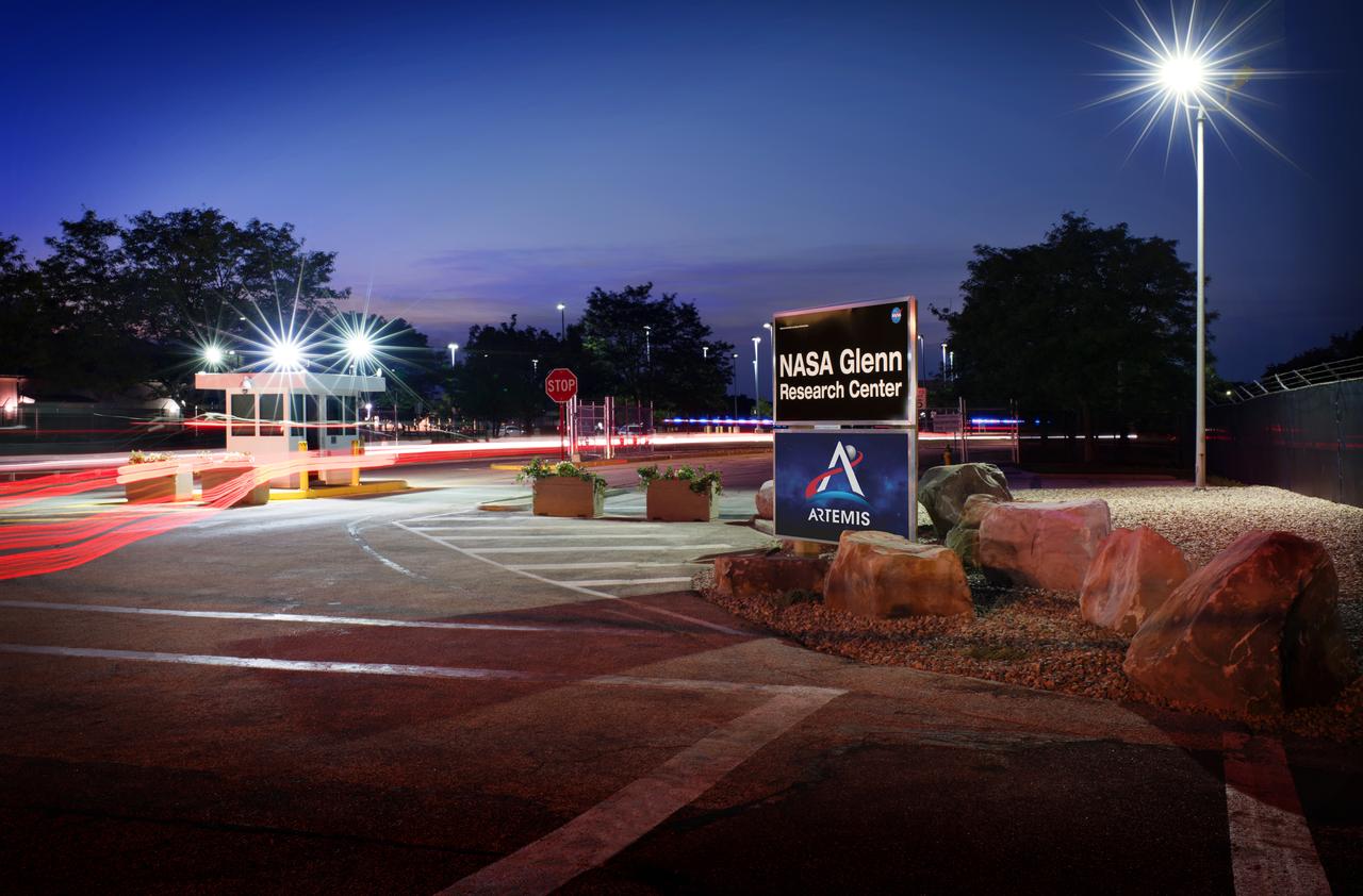
The newly renovated NASA Glenn Research Center, GRC Lewis Field West Gate at dusk.
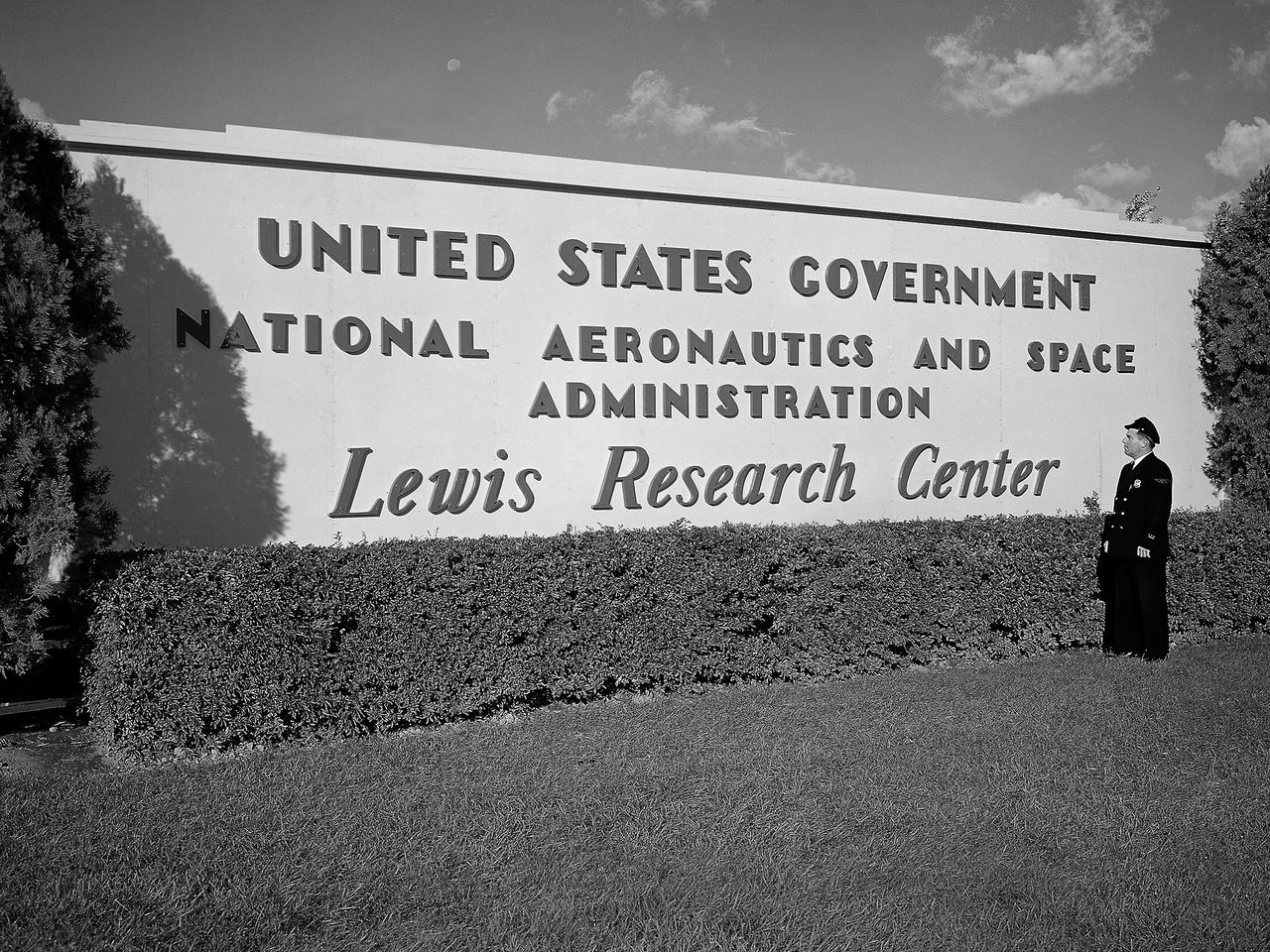
A security guard examines the new sign near the entrance to the Lewis Research Center one day after the National Aeronautics and Space Administration (NASA) was officially established. NASA came into being on October 1, 1958, and the National Advisory Committee for Aeronautics (NACA) Lewis Flight Propulsion Laboratory became the NASA Lewis Research Center. Lewis underwent a major reorganization and began concentrating its efforts almost exclusively on the space program. NACA Lewis researchers had been advocating further space research for years. As early as 1955, Lewis management urged the NACA expand its rocket engine research as a logical extension of its aircraft engine work. Lewis management claimed that space exploration was imperative for the nation’s survival during the Cold War. They called for an annual 25-percent increase in the NACA’s staff, a new space laboratory, a launching center, communications center, and other facilities. They were basically outlining what would be needed for the new space agency. During NASA’s first two years of existence, Lewis refocused its efforts almost completely on the space program. Less than 10 percent of the annual budget was dedicated to aeronautics. In the aftermath that followed President Kennedy’s April 1961 “Urgent Needs” address to Congress, NASA was given a seemingly unlimited budget. The Agency reorganized and began swelling its ranks through a massive recruiting effort to accomplish the accelerated lunar landing mission. Lewis personnel increased from approximately 2,700 in 1961 to over 4,800 in 1966.
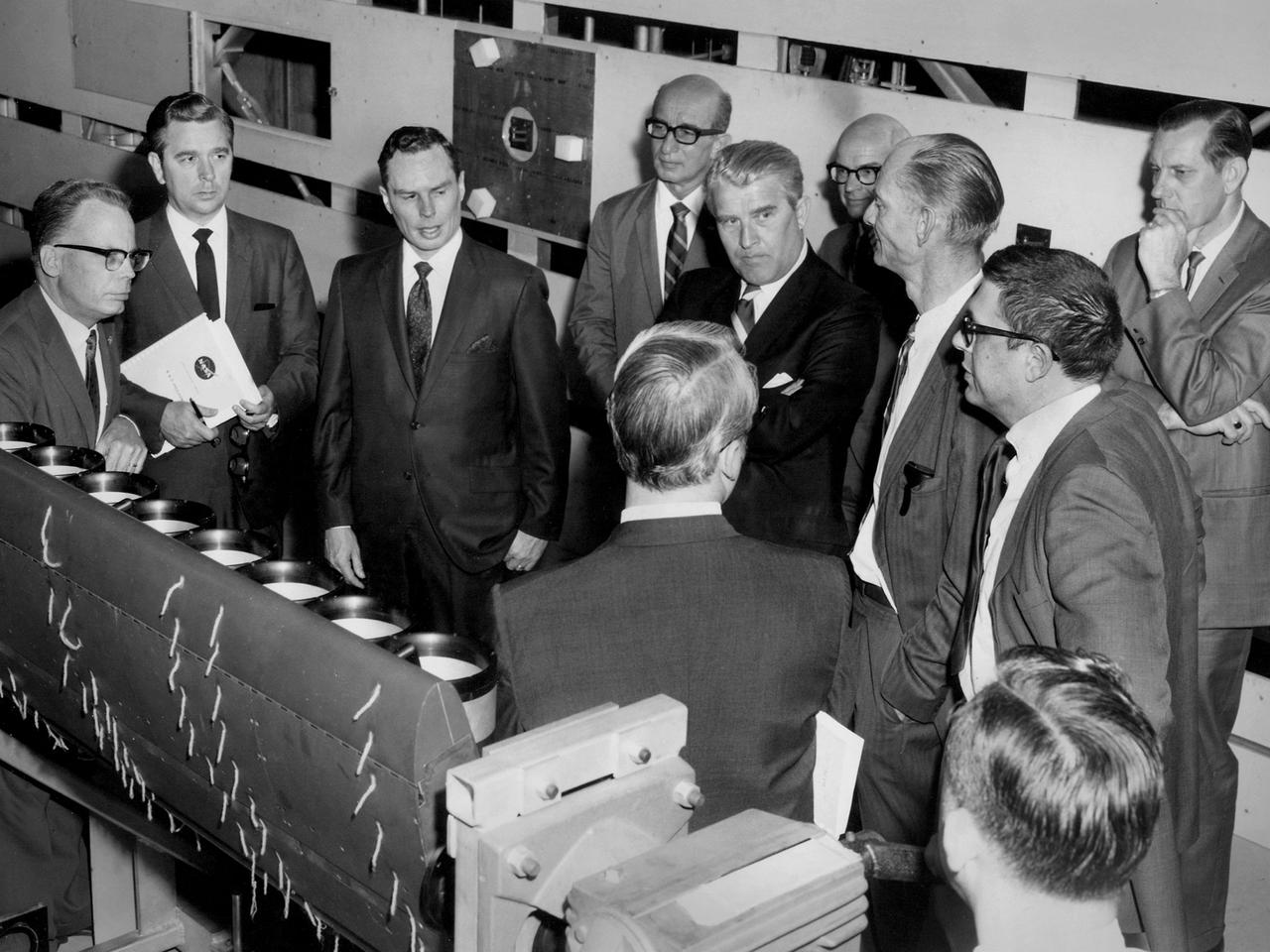
Werner von Braun, National Aeronautics and Space Administration (NASA) Deputy Associate Administrator for Planning, among a group from Headquarters touring the Lewis Research Center in Cleveland, Ohio. Lewis Special Projects Chief Newell Sanders, left, describes a Short Takeoff and Landing wing-propulsion model. Lewis had recently converted the return leg of its 8- by 6-Foot Supersonic Wind Tunnel into the 9- by 15-Foot Low Speed Wind Tunnel to investigate Vertical and Short Takeoff and Landing propulsion systems. Gathered from the left near Sanders are James Daniels, Headquarters Executive Secretary; Oran Hicks, Acting Associate Administrator for the Headquarters Office of Advanced Research and Technology; Eugene Manganiello, Lewis Deputy Director; von Braun; Dr. Walter Olson, Lewis Assistant Director; Bruce Lundin, Lewis Director and Dr. Bernard Lubarsky, Lewis Assistant Director. Just months before this photograph, NASA asked von Braun to give up his post as Director of the Marshall Space Flight Center after nearly ten years in order to head up the strategic planning effort for the agency from Washington DC. Von Braun retired from NASA two years later.
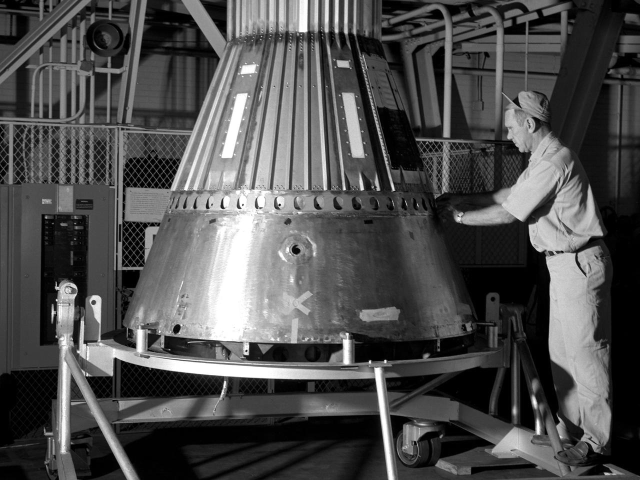
A NASA mechanic secures the afterbody to a Mercury capsule in the hangar at the Lewis Research Center. The capsule was one of two built at Lewis for the “Big Joe” launches scheduled for September 1959. The initial phase of Project Mercury consisted of a series of unmanned launches using the Air Force’s Redstone and Atlas boosters and the Langley-designed Little Joe boosters. The first Atlas launch, referred to as “Big Joe”, was a single attempt early in Project Mercury to use a full-scale Atlas booster to simulate the reentry of a mock-up Mercury capsule without actually placing it in orbit. The overall design of Big Joe had been completed by December 1958, and soon thereafter project manager Aleck Bond assigned NASA Lewis the task of designing the electronic instrumentation and automatic stabilization system. Lewis also constructed the capsule’s lower section, which contained a pressurized area with the electronics and two nitrogen tanks for the retrorockets. Lewis technicians were responsible for assembling the entire capsule: the General Electric heatshield, NASA Langley afterbody and recovery canister, and Lewis electronics and control systems. On June 9, 1959, the capsule was loaded on an air force transport aircraft and flown to Cape Canaveral. A team of 45 test operations personnel from Lewis followed the capsule to Florida and spent the ensuing months preparing it for launch. The launch took place in the early morning hours of September 9, 1959.
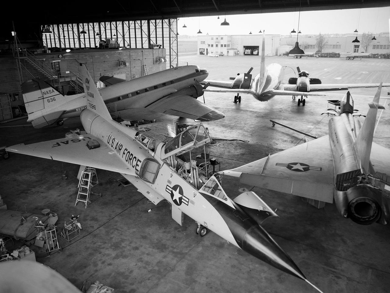
Several aircraft parked inside the Flight Research Building, or hangar, at the National Aeronautics and Space Administration (NASA) Lewis Research Center in Cleveland, Ohio. A Convair F-106B Delta Dart is in the foreground, a Convair F-102A Delta Dagger is to the right, a Douglas DC-3 is in the back to left, and a Convair T-29 is in background. Lewis’ Martin B-57B Canberra is not seen in this photograph. The F-102A had just been acquired by Lewis to serve as a chase plane for the F-106B. The Lewis team removed the weapons system and 700 pounds of wire from the F-106B when it was acquired on October 20, 1966. The staff cut holes in the wings and modified the elevons to mount the test nacelles. A 228-gallon fuel tank was installed in the missile bay, and the existing wing tanks were used for instrumentation. This photograph contains a rare view of the Block House, seen to the left of the aircraft. Lewis acquired three large developmental programs in 1962—the Centaur and Agena rockets and the M-1 engine. The center was short on office space at the time, and its flight research program was temporarily on the wane. Lewis management decided to construct a large cinderblock structure inside one half of the hangar to house the new personnel. This structure was used until 1965 when the new Developmental Engineering Building was built. The Block House was eventually torn down in 1973.
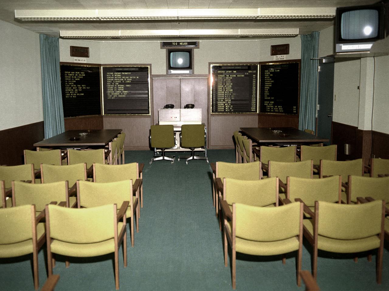
A Centaur rocket control room in the Development Engineering Building (DEB) at the National Aeronautics and Space Administration (NASA) Lewis Research Center in Cleveland, Ohio. The DEB, completed in the mid-1960s, provided office space for several hundred development engineers outside the center’s main gate. The location of the DEB emphasized the development staff’s separation from the research side of the laboratory. This control room at Lewis was directly linked to Cape Kennedy. The Lewis staff in Cleveland could monitor and back up the Lewis launch team in the actual control room at the Cape. This photograph was taken during the preparations for the Titan-Centaur-Helios launch on December 10, 1974. The panels to the left listed the countdown events for the Centaur rocket. The launch countdown clock can be seen above these panels. The two panels on the right listed events predicted to occur during the flight and the availability of the tracking stations. The clock above the panels indicated the time remaining before the launch window expired. The Launch Vehicles Division was created in 1969 to manage the launches of all Centaur and Agena rockets. The Launch Vehicles Division worked with the engineers to design the payload in a manner that ensured that its size and weight were within Centaur’s parameters. They also developed the proper trajectory analysis for the launch. These trajectories often had to be adjusted if the launch did not occur on the planned date.

Doreen Zudell takes over as the Editor of the Lewis News, Center Newsletter
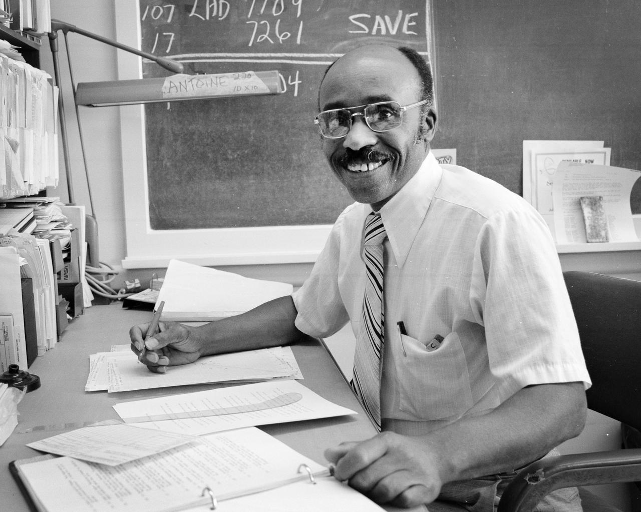
Electrochemistry Branch, Research Contributions to the NASA Mission at the Lewis Research Center
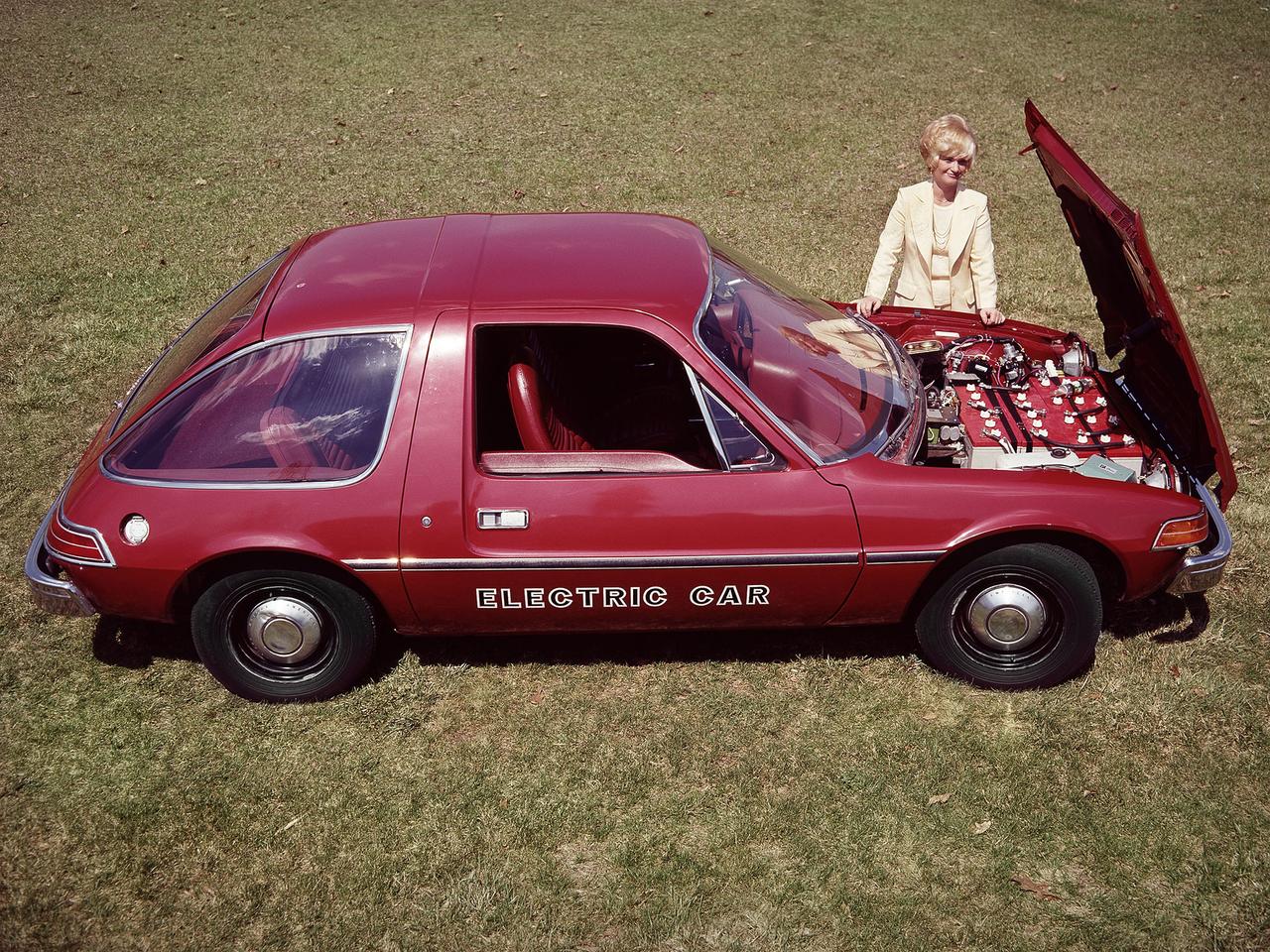
The National Aeronautics and Space Administration (NASA) Lewis Research Center tested 16 commercially-manufactured electric vehicles, including this modified Pacer, during the mid-1970s. The Electric Vehicle Project was just one of several energy-related programs that Lewis and the Energy Research and Development Administration (ERDA) undertook in the mid-1970s. NASA and ERDA embarked on this program in 1976 to determine the state of the current electric vehicle technology. As part of the project, Lewis tested a fleet composed of every commercially available electric car. The Cleveland-area Electric Vehicle Associates modified an American Motors Pacer vehicle to create this Change-of-Pace Coupe. It was powered by twenty 6-volt batteries whose voltage could be varied by a foot control. The tests analyzed the vehicle’s range, acceleration, coast-down, braking, and energy consumption. Some of the vehicles had analog data recording systems to measure the battery during operation and sensors to determine speed and distance. Lewis researchers found that the vehicle performance varied significantly from model to model. In general, the range, acceleration, and speed were lower than conventional vehicles. They also found that traditional gasoline-powered vehicles were as efficient as the electric vehicles. The researchers concluded, however, that advances in battery technology and electric drive systems would significantly improve the performance and efficiency.
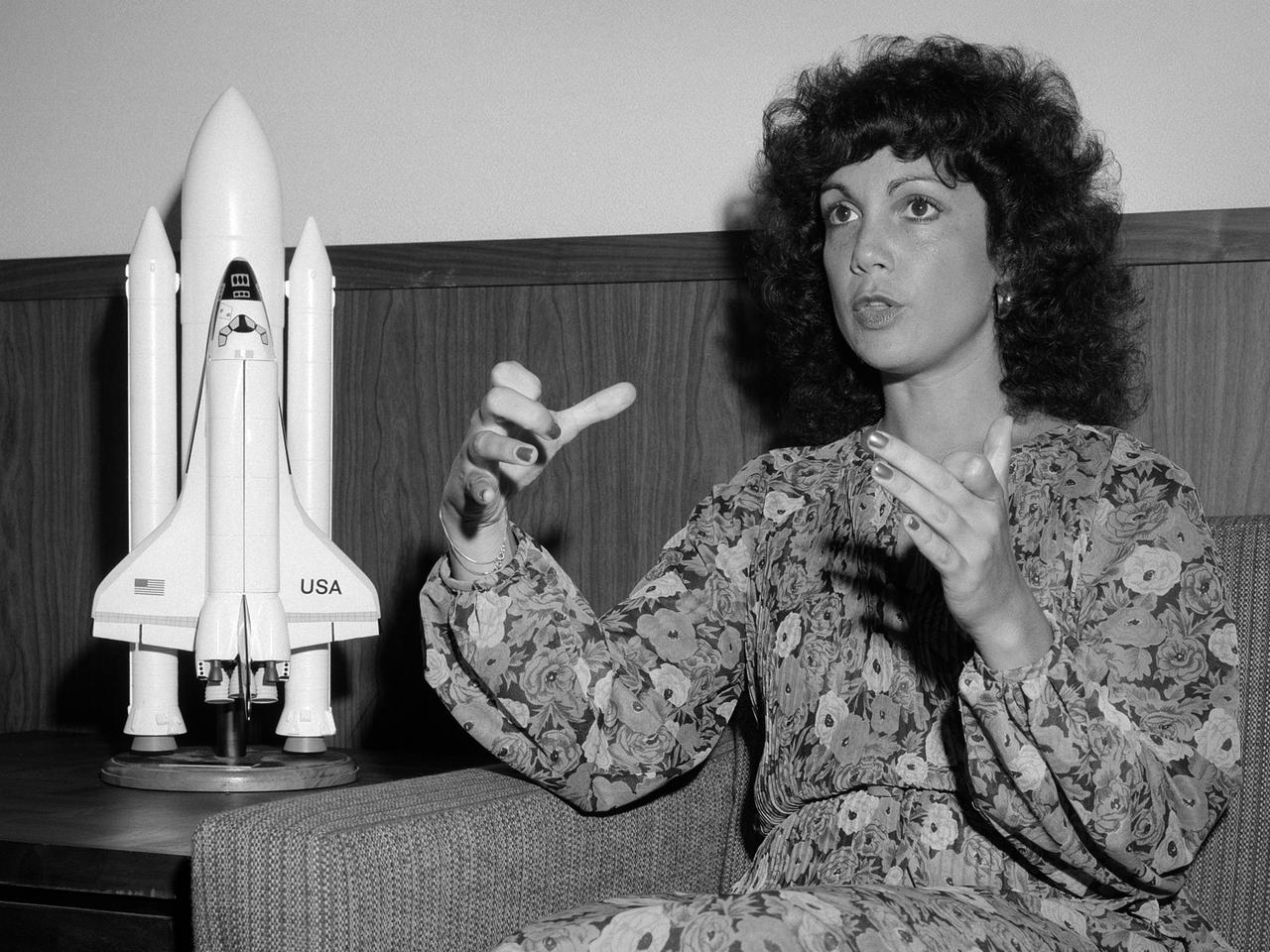
Astronaut Judy Resnik visits the National Aeronautics and Space Administration (NASA) Lewis Research Center on July 18, 1979, the tenth anniversary of the Apollo 11 mission. The event, sponsored by the center’s Public Information Office, was attended by Lewis staff, Cleveland-area media and personalities, and the public. During her time in Cleveland, Resnik appeared on a local television program, gave a press conference, lunched with NASA officials, addressed employees at Lewis, and then met the public at the center’s Visitors Information Center. Resnik related her recent experiences as one of the first US female astronauts and her duties as a mission specialist. The Akron, Ohio native earned a Bachelor’s degree in electrical engineering from Carnegie-Mellon University in 1970 and a doctorate in electrical engineering from the University of Maryland in 1977. Resnik served as a biomedic engineer and staff fellow in the Laboratory of Neurophysiology at the National Institutes of Health from 1974 to 1977, where she performed biological research experiments on visual systems. She served as a senior systems engineer in private industry prior to her selection as an astronaut. Resnik first flew as a mission specialist on STS 41-D, Discovery’s maiden flight, in 1984. Resnik was killed in the January 28, 1986 Challenger accident.

Visit to Glenn Research Center at Lewis Field by Mercury 13 Astronaut Trainee, Wally Funk
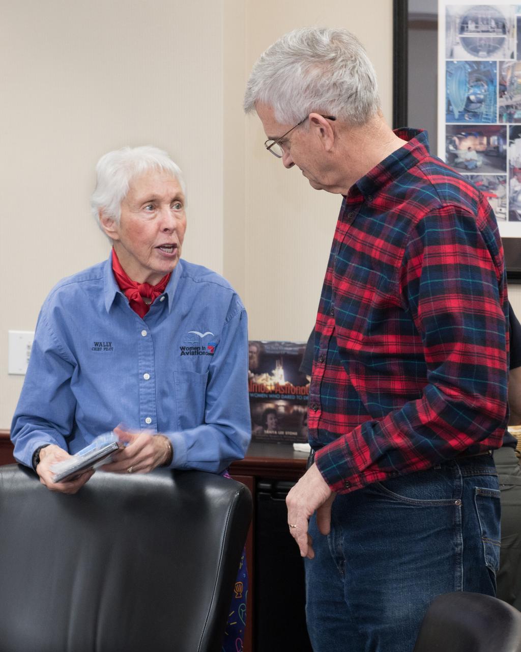
Visit to Glenn Research Center at Lewis Field by Mercury 13 Astronaut Trainee, Wally Funk
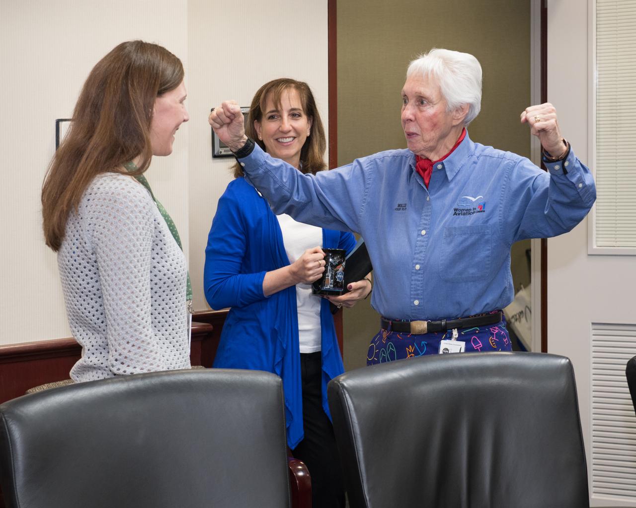
Visit to Glenn Research Center at Lewis Field by Mercury 13 Astronaut Trainee, Wally Funk
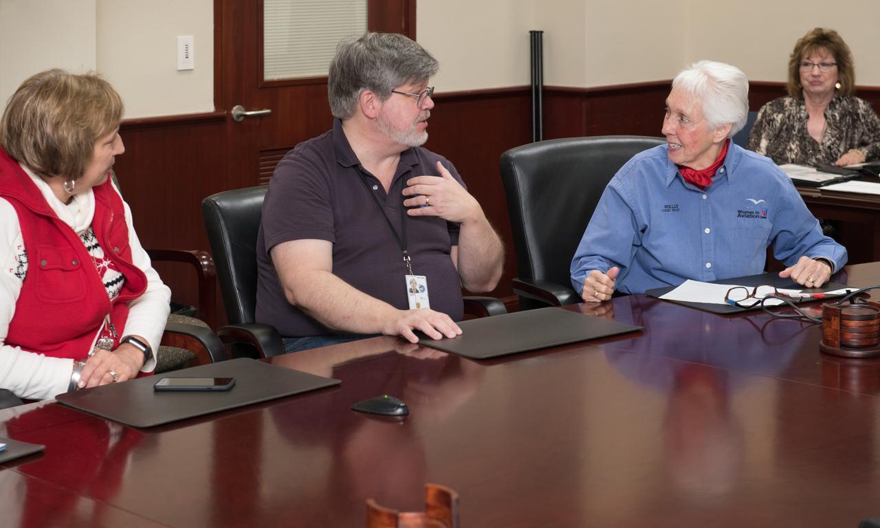
Visit to Glenn Research Center at Lewis Field by Mercury 13 Astronaut Trainee, Wally Funk
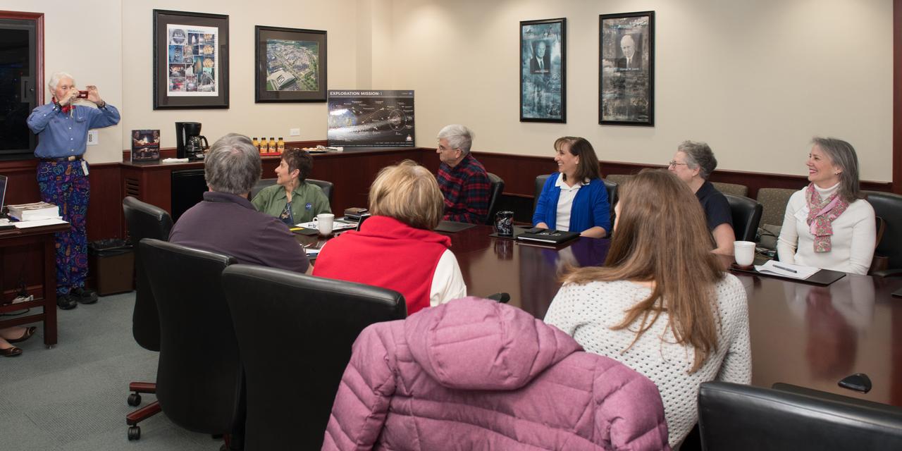
Visit to Glenn Research Center at Lewis Field by Mercury 13 Astronaut Trainee, Wally Funk
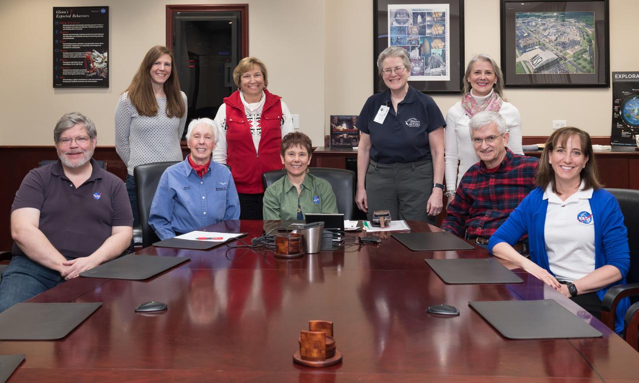
Visit to Glenn Research Center at Lewis Field by Mercury 13 Astronaut Trainee, Wally Funk
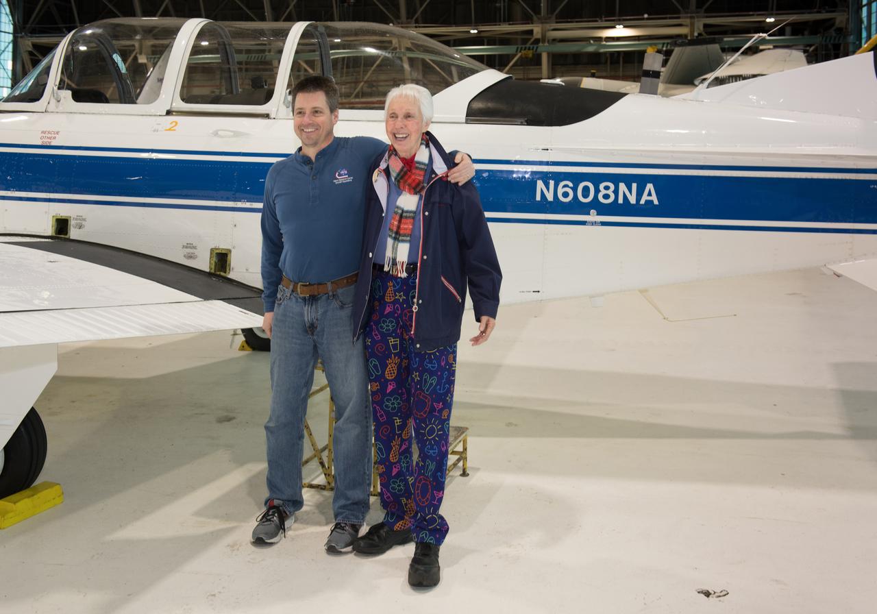
Visit to Glenn Research Center at Lewis Field by Mercury 13 Astronaut Trainee, Wally Funk
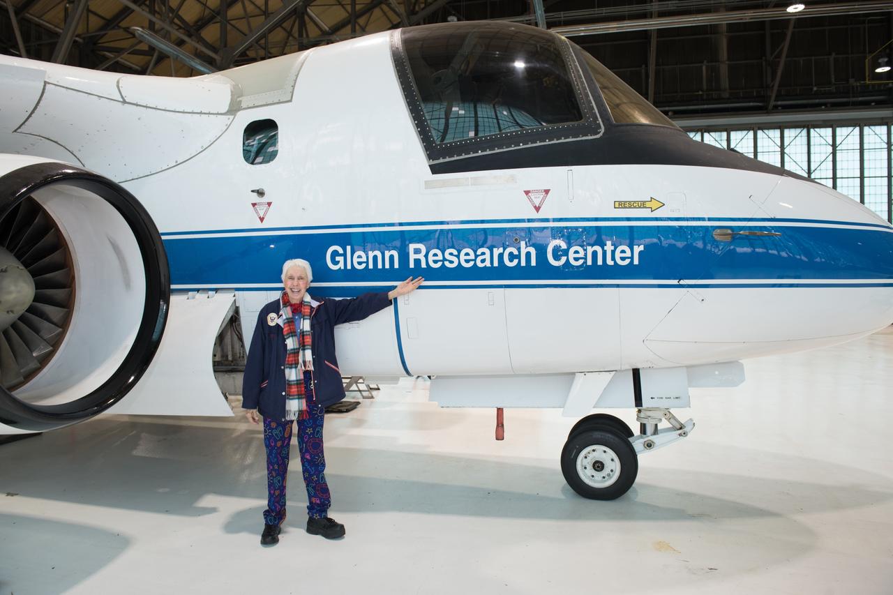
Visit to Glenn Research Center at Lewis Field by Mercury 13 Astronaut Trainee, Wally Funk
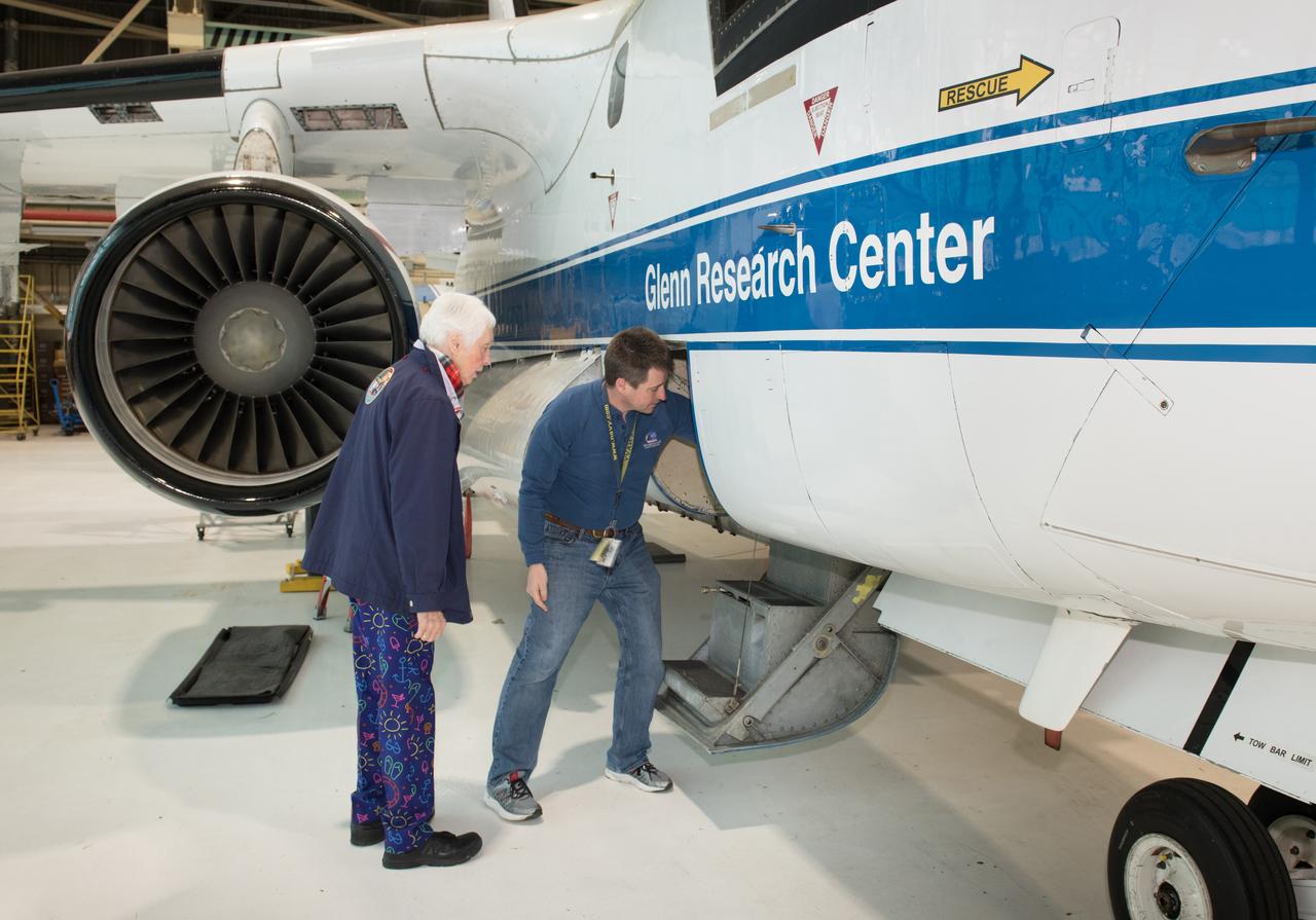
Visit to Glenn Research Center at Lewis Field by Mercury 13 Astronaut Trainee, Wally Funk
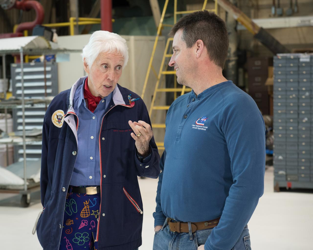
Visit to Glenn Research Center at Lewis Field by Mercury 13 Astronaut Trainee, Wally Funk
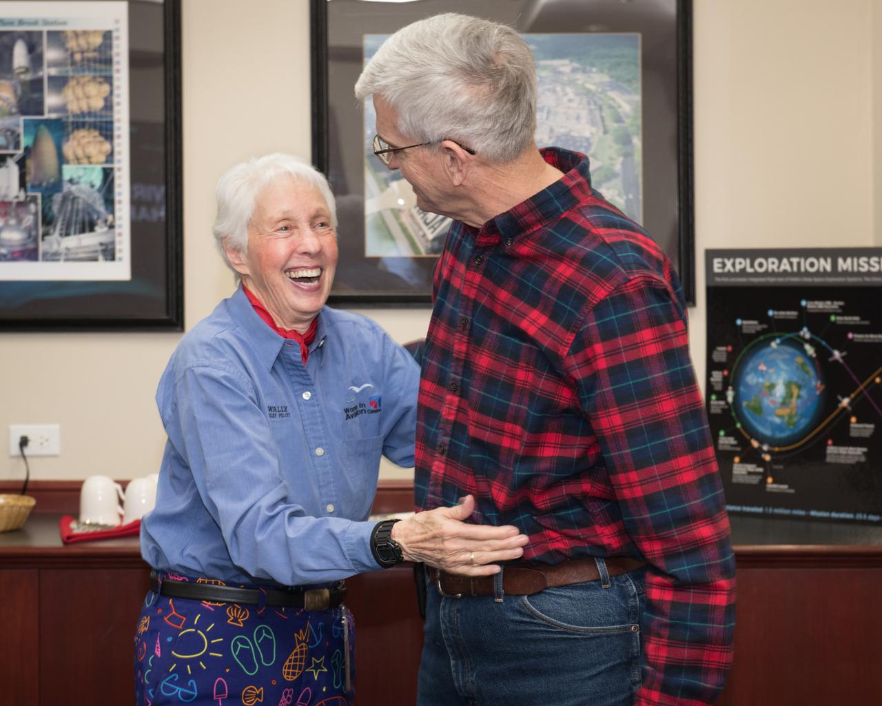
Visit to Glenn Research Center at Lewis Field by Mercury 13 Astronaut Trainee, Wally Funk
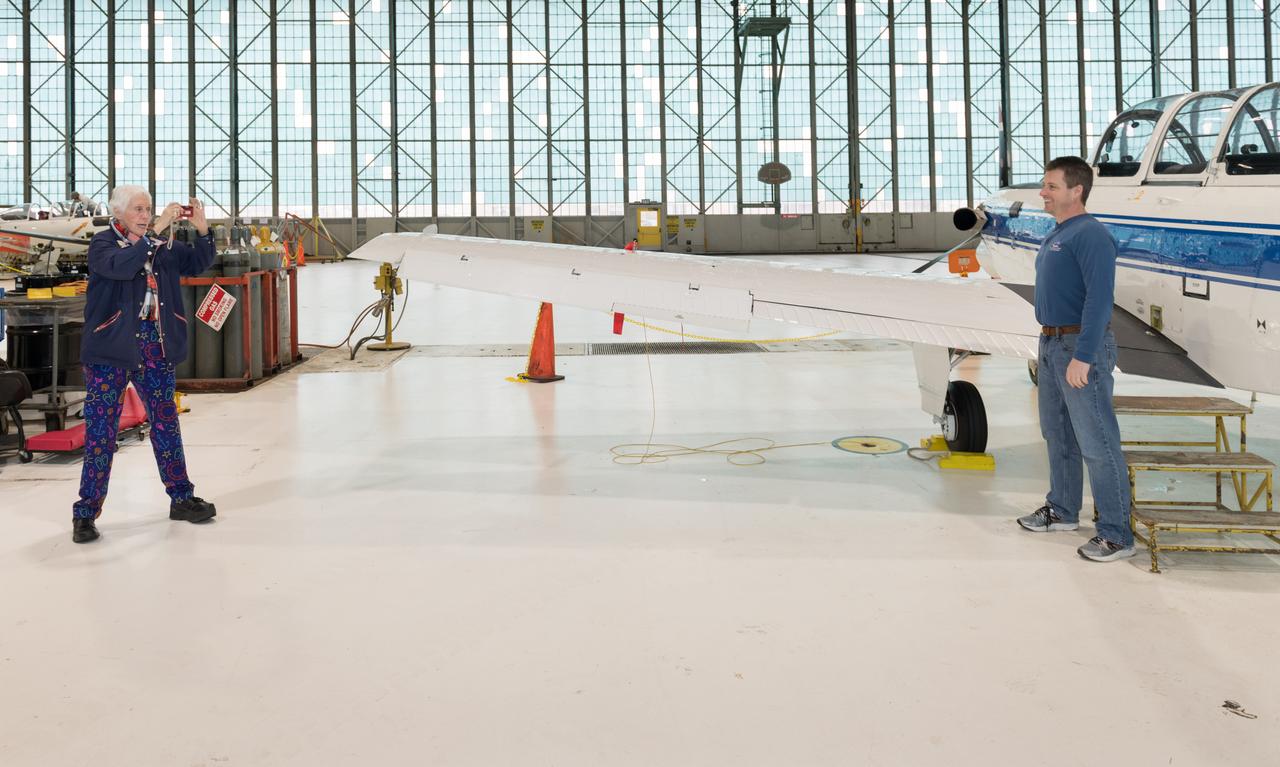
Visit to Glenn Research Center at Lewis Field by Mercury 13 Astronaut Trainee, Wally Funk
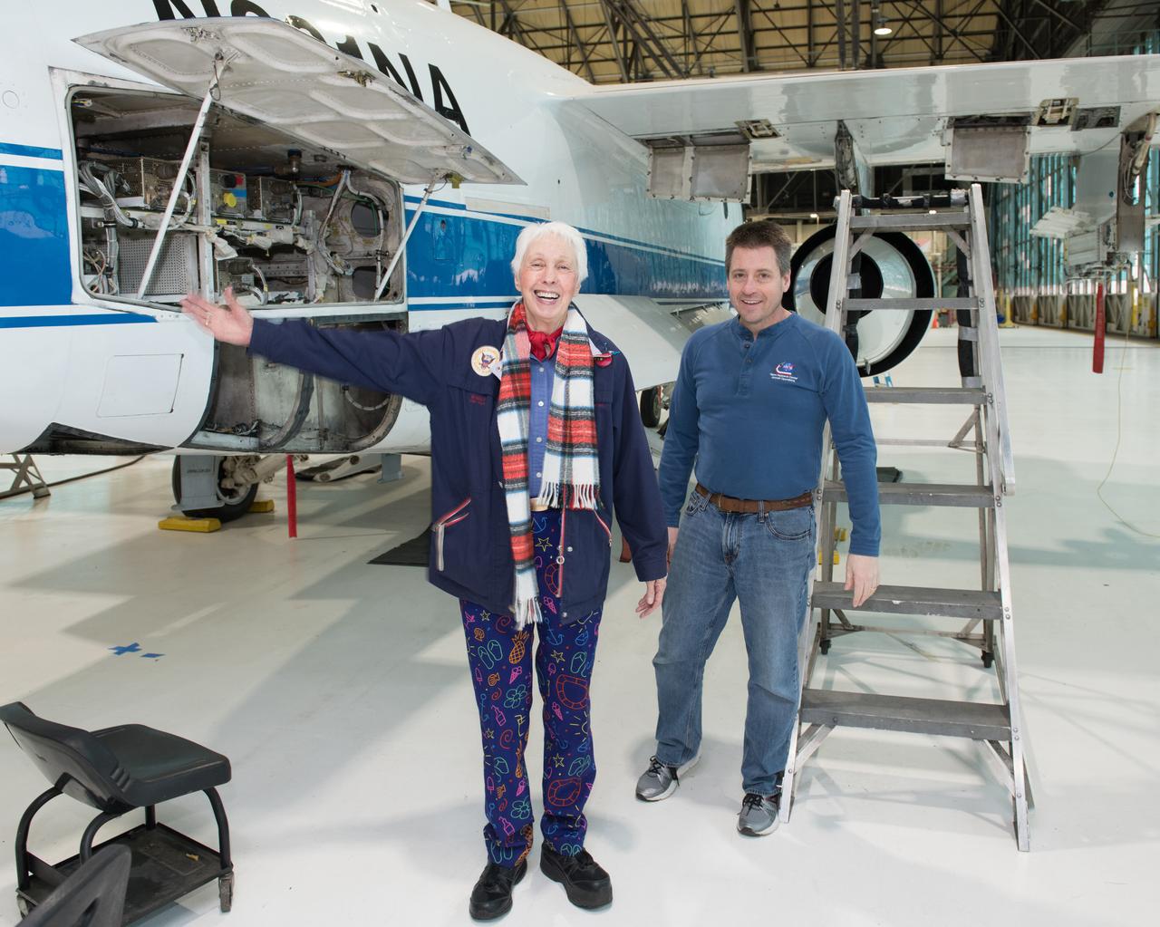
Visit to Glenn Research Center at Lewis Field by Mercury 13 Astronaut Trainee, Wally Funk
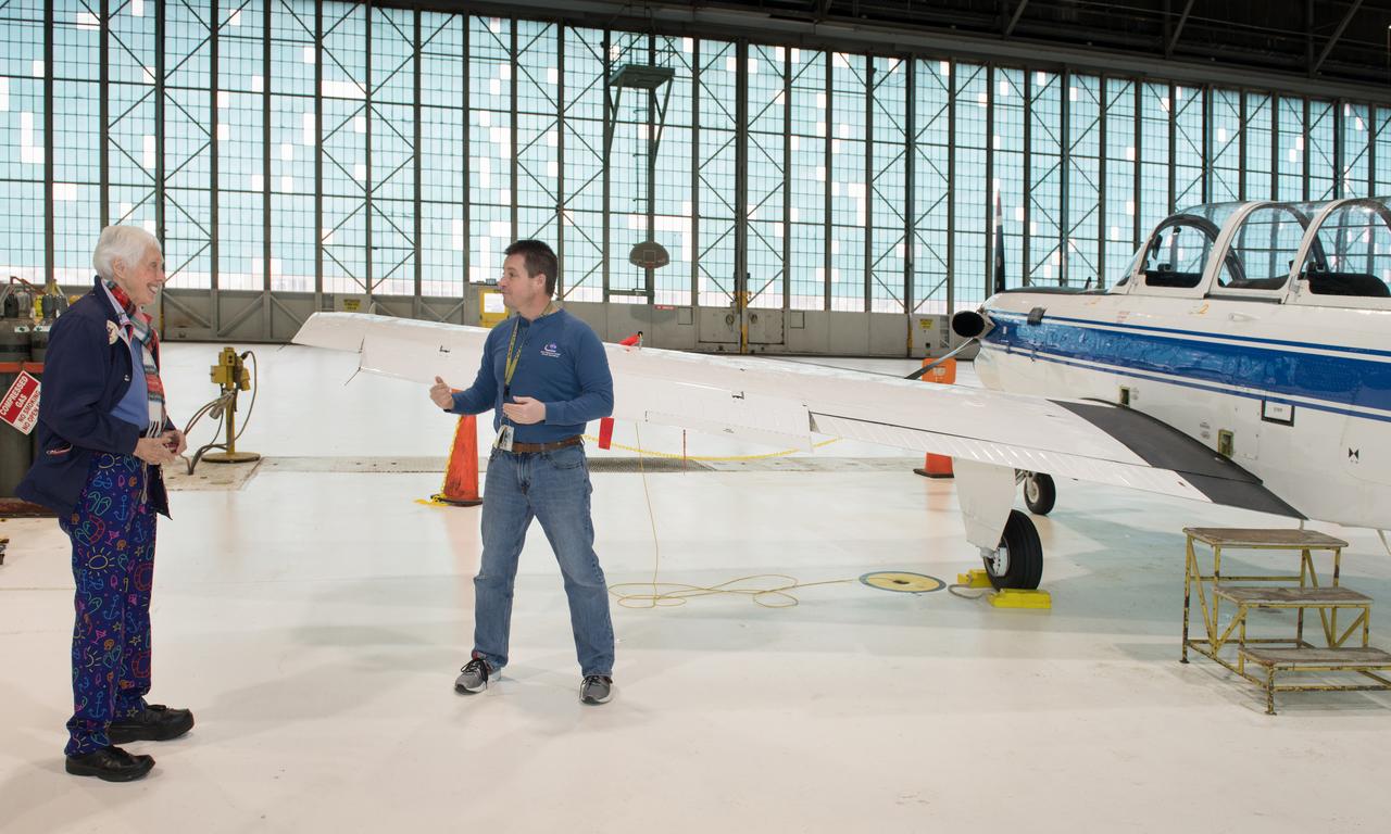
Visit to Glenn Research Center at Lewis Field by Mercury 13 Astronaut Trainee, Wally Funk
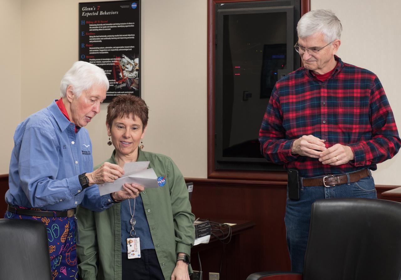
Visit to Glenn Research Center at Lewis Field by Mercury 13 Astronaut Trainee, Wally Funk

Visit to Glenn Research Center at Lewis Field by Mercury 13 Astronaut Trainee, Wally Funk
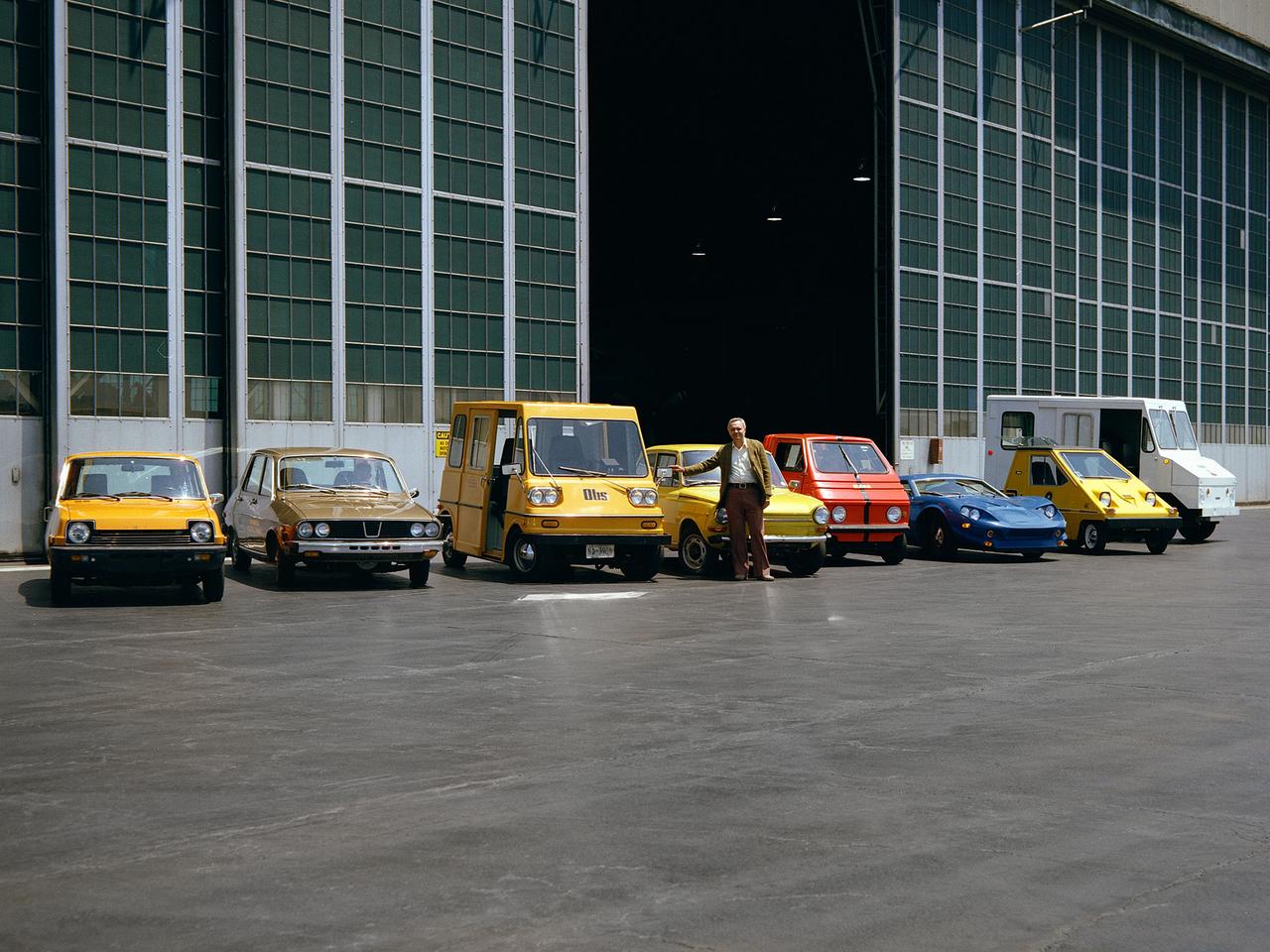
The National Aeronautics and Space Administration (NASA) Lewis Research Center tested 16 commercially-manufactured electric vehicles, including these, during the mid-1970s. Lewis and the Energy Research and Development Administration (ERDA) engaged in several energy-related programs in the mid-1970s, including the Electric Vehicle Project. NASA and ERDA undertook the program in 1976 to determine the state of the current electric vehicle technology. The tests were primarily conducted on a 7.5-mile track at the Transportation Research Center located approximately 160 miles southwest of Cleveland, Ohio. Some of the vehicles had analog data recording systems to measure the battery during operation and sensors to determine speed and distance. The tests analyzed the vehicle’s range, acceleration, coast-down, braking, and energy consumption. From left to right: RIPP-Electric, EVA Contactor, Otis P-500, C.H. Waterman DAF, Zagato Elcar, unknown, Sebring-Vanguard Citicar, and Hattronic Minivan
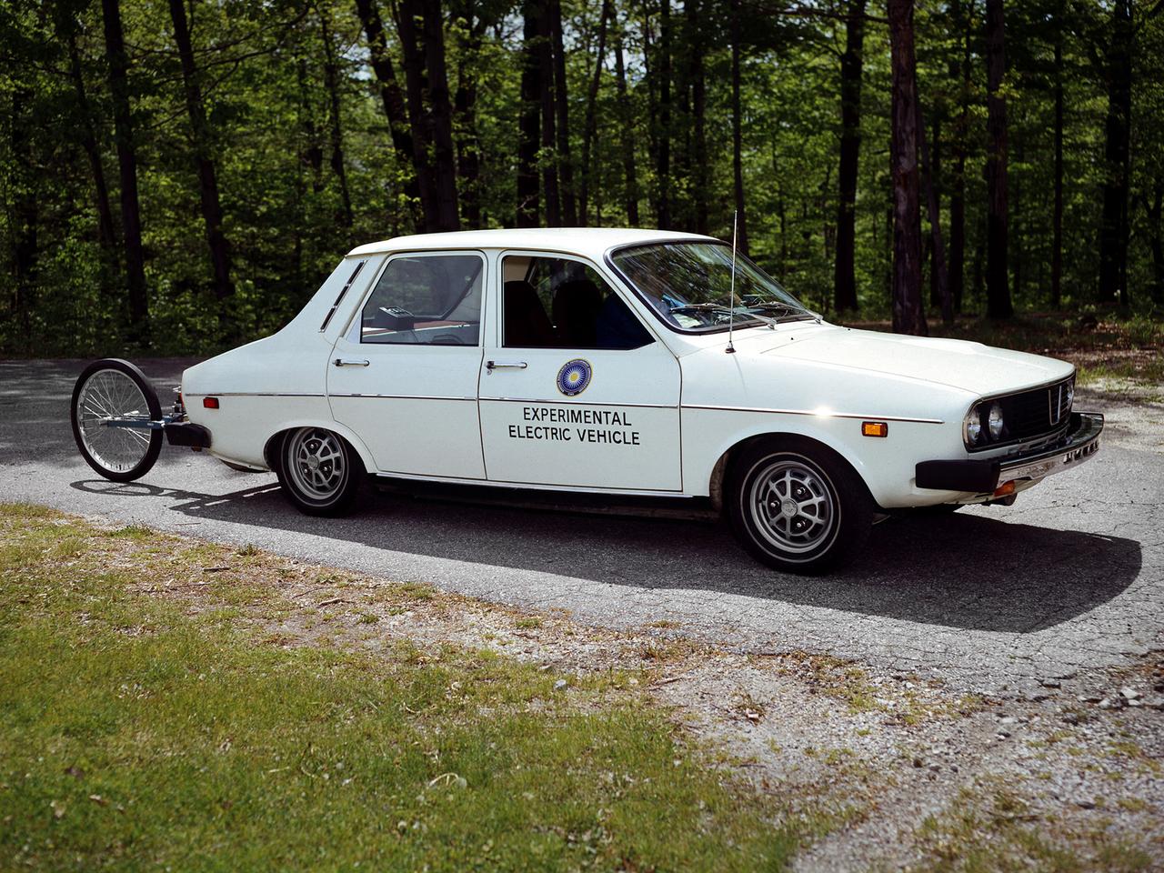
The National Aeronautics and Space Administration (NASA) Lewis Research Center tested 16 commercially-manufactured electric vehicles, including this Metro, during the mid-1970s. Lewis and the Energy Research and Development Administration (ERDA) engaged in several energy-related programs in the mid-1970s, including the Electric Vehicle Project. NASA and ERDA undertook the program in 1976 to determine the state of the current electric vehicle technology. As part of the project, Lewis and ERDA tested every commercially available electric car model. Electric Vehicle Associates, located in a Cleveland suburb, modified a Renault 12 vehicle to create this Metro. Its 1040-pound golfcart-type battery provided approximately 106 minutes of operation. The tests analyzed the vehicle’s range, acceleration, coast-down, braking, and energy consumption. Some of the vehicles had analog data recording systems to measure the battery during operation and sensors to determine speed and distance. The researchers found the performance of the different vehicles varied significantly. In general, the range, acceleration, and speed were lower than that found on conventional vehicles. They also found that traditional gasoline-powered vehicles were as efficient as the electric vehicles. The researchers concluded, however, that advances in battery technology and electric drive systems would significantly improve efficiency and performance.
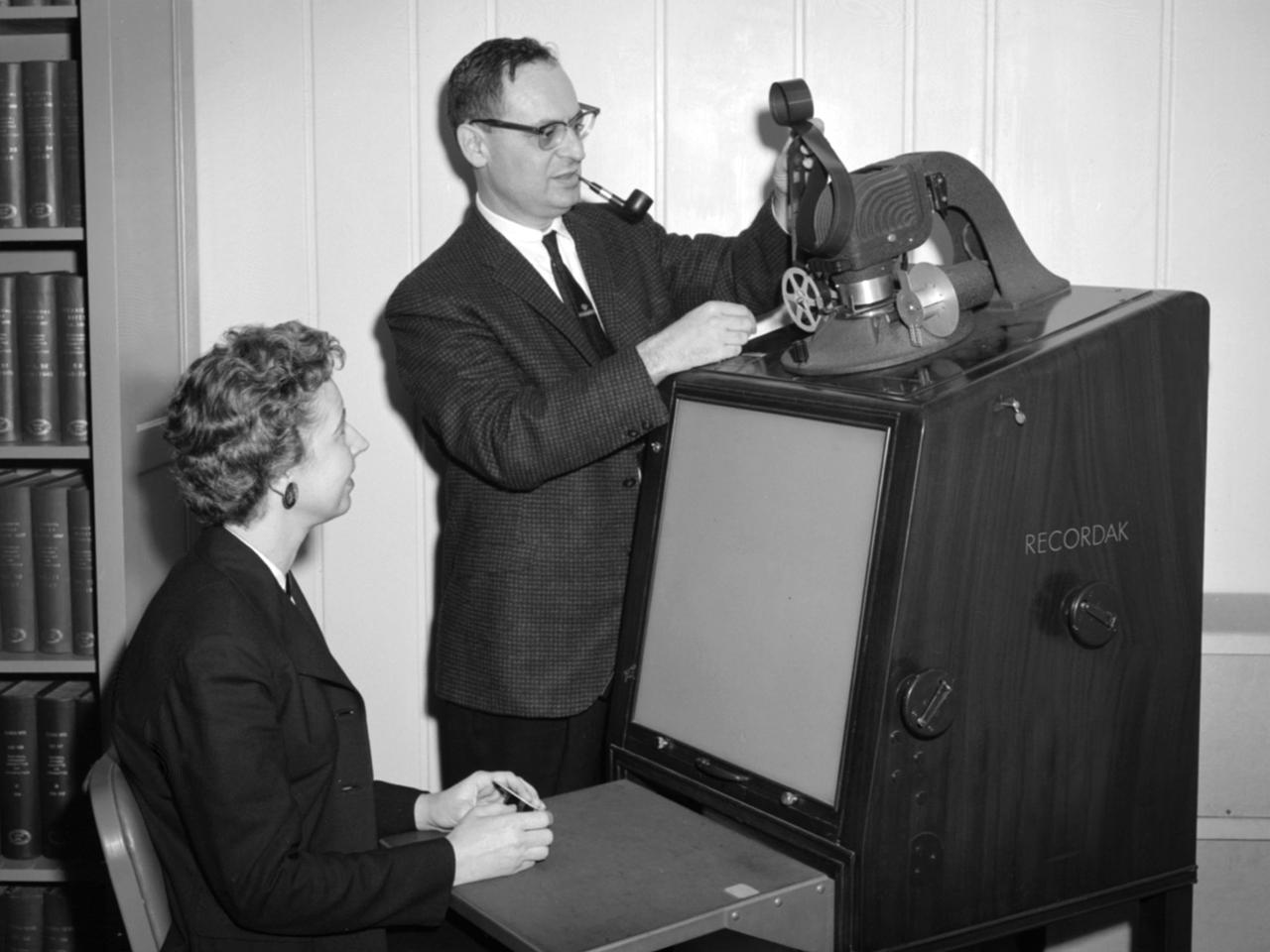
Jean Neidengard and George Mandel operate a Kodak Recordak microfilm reader in the library at the National Aeronautics and Space Administration (NASA) Lewis Research Center. The library was located in the Administration Building until the mid-1960s. It was then moved to the Propulsion Systems Laboratory Office Building. In 2008 the library was moved once again, to the Research Analysis Center. At the time of this photograph, the Lewis library claimed to possess “One of the most complete aero-technical collections in the world.” It was doing a brisk business in the early 1960s. During 1960 alone the library acquired 19,000 new documents and provided 100,000 documents to customers. The library’s eleven-person staff provided reference services, archived technical reports, and supplied periodicals. The staff also included Sam Reiss, a full-time translator who could read 30 languages. He translated technical reports from all over the world for the Lewis research staff. Jean Neidengard oversaw the secret Atomic Energy Commission (AEC) documents in the collection. NASA was partnering with the AEC at the time on Nuclear Engine for Rocket Vehicle Application (NERVA) program. NASA Lewis was the agency’s lead center in the NERVA program. Neidengard’s husband Bill was the head mechanic in the Propulsion Systems Laboratory. George Mandel led the library staff from 1955 to 1968.
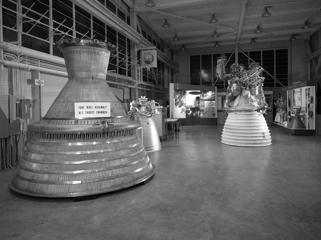
An array of rocket engines displayed in the Propulsion Systems Laboratory for the 1966 Inspection held at the National Aeronautics and Space Administration (NASA) Lewis Research Center. Lewis engineers had been working on chemical, nuclear, and solid rocket engines throughout the 1960s. The engines on display are from left to right: two scale models of the Aerojet M-1, a Rocketdyne J-2, a Pratt and Whitney RL-10, and a Rocketdyne throttleable engine. Also on display are several ejector plates and nozzles. The Chemical Rocket Division resolved issues such as combustion instability and screech, and improved operation of cooling systems and turbopumps. The 1.5-million pound thrust M-1 engine was the largest hydrogen-fueled rocket engine ever created. It was a joint project between NASA Lewis and Aerojet-General. Although much larger in size, the M-1 used technology developed for the RL-10 and J-2. The M-1 program was cancelled in late 1965 due to budget cuts and the lack of a post-Apollo mission. The October 1966 Inspection was the culmination of almost a year of events held to mark the centers’ 25th anniversary. The three‐day Inspection, Lewis’ first since 1957, drew 2000 business, industry, and government executives and included an employee open house. The visitors witnessed presentations at the major facilities and viewed the Gemini VII spacecraft, a Centaur rocket, and other displays in the hangar. In addition, Lewis’ newest facility, the Zero Gravity Facility, was shown off for the first time.
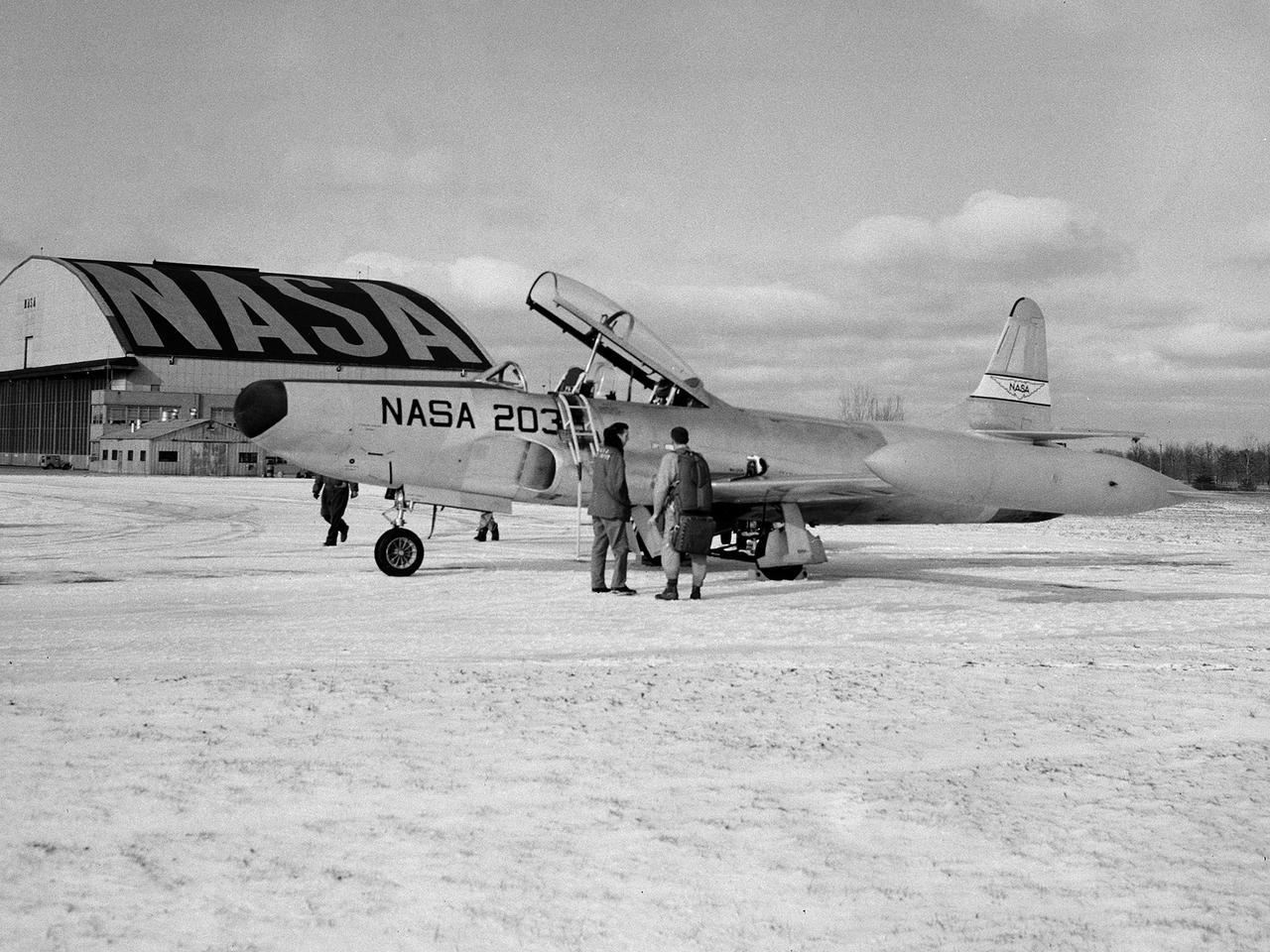
A Lockheed F-94B Starfire on the hangar apron at the National Aeronautics and Space Administration (NASA) Lewis Research Center in Cleveland, Ohio. The Air Force contracted Lockheed in November 1948 to create the new F-94s fighters. The first test flight occurred only months later in April 1949. This quick turnaround was due to the fact that the F-94 was based largely on the TF-80 fighter and constructed with parts from the P-80, including its two General Electric I-40 turbojet engines. The F-94Bs entered the Korean War in late 1951, but were initially prevented from flying over enemy territory due to fear that their fire control system would be copied by the enemy if an F-94B went down. The Starfire went on to perform scores of missions escorting B-29 and B-26 bombers deep into enemy territory and acting as interceptors against enemy fighters. In mid-1954 the F-94s were retired from active military service. Lewis acquired the F-94B Starfire in April 1956. At the time, the aircraft industry was preparing for the first use of jet engines for commercial aviation. The amount of noise generated by the engines was a major obstacle. Lewis undertook an extensive program to understand the causes of the noise and develop methods for reducing it. This program included the study of aerodynamic sound at high speed and altitude using the F-94B.
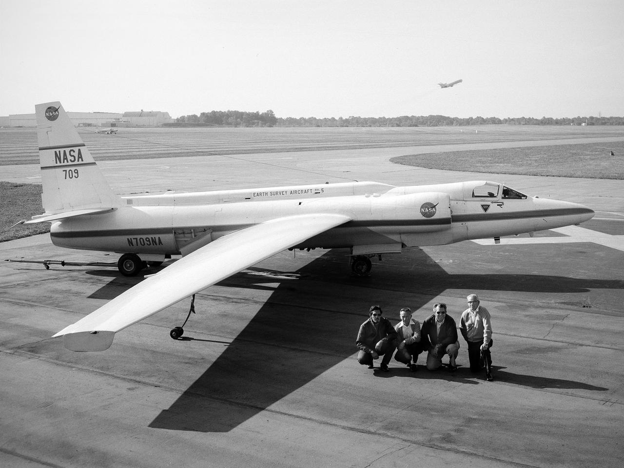
A National Aeronautics and Space Administration (NASA) Lockheed U-2 aircraft on display at the 1973 Inspection of the Lewis Research Center in Cleveland, Ohio. Lockheed developed the U-2 as a high-altitude reconnaissance aircraft in the early 1950s before satellites were available. The U-2 could cruise over enemy territory at 70,000 feet and remain impervious to ground fire, interceptor aircraft, and even radar. An advanced camera system was designed specifically for the aircraft. The pilot is required to use a pressure suit similar to those worn by astronauts. NASA’s Ames Research Center received two U-2 aircraft in April 1971 to conduct high-altitude research. They were used to study and monitor various Earth resources, celestial bodies, atmospheric chemistry, and oceanic processes. NASA replaced its U-2s with ER-2 aircraft in 1981 and 1989. The ER-2s were designed to carry up to 2600 pounds of scientific equipment. The ER-2 program was transferred to Dryden Flight Research Center in 1997. Since the inaugural flight for this program on August 31, 1971, NASA’s U-2 and ER-2 aircraft have flown more than 4500 data missions and test flights for NASA, other federal agencies, states, universities, and the private sector.
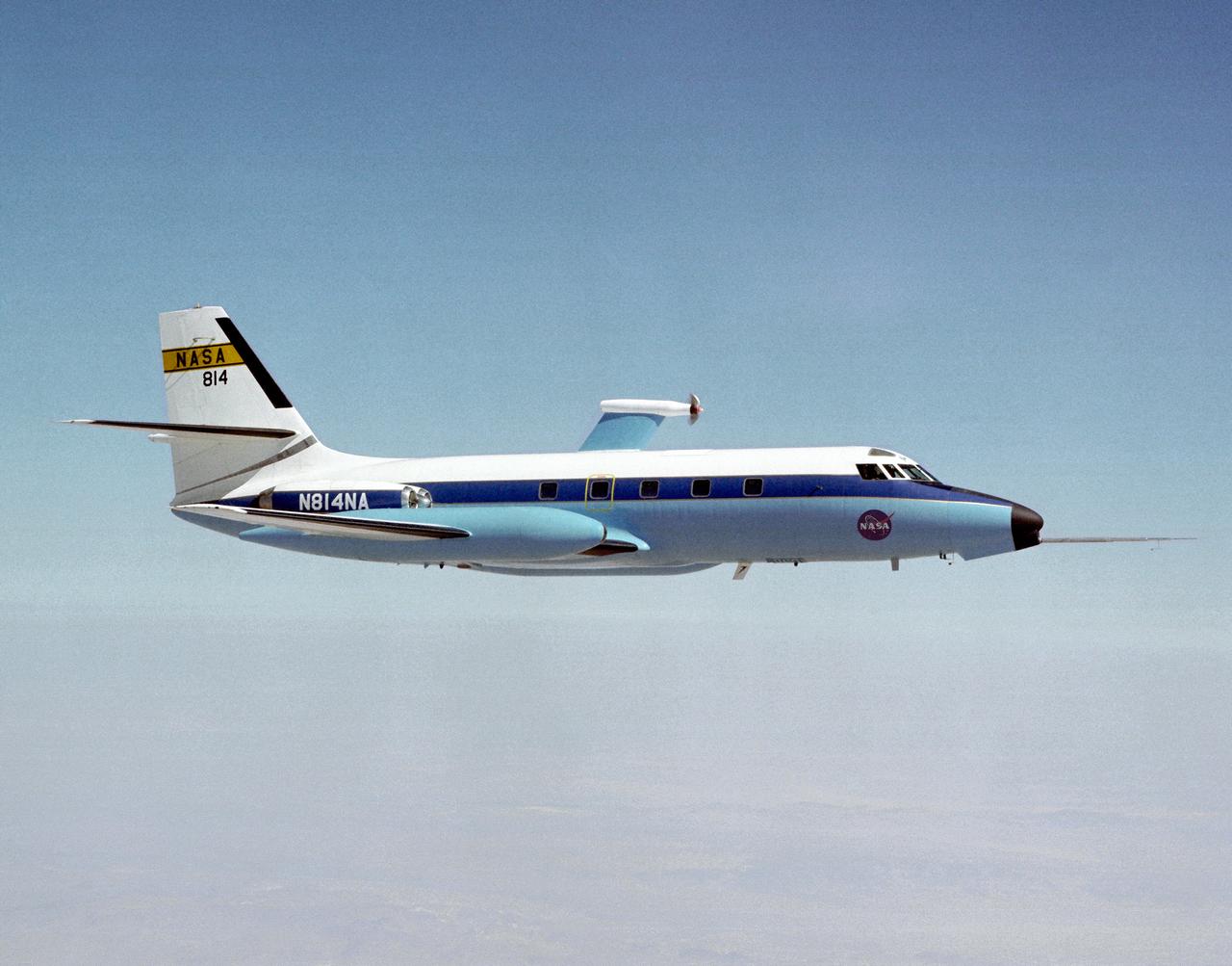
The Dryden C-140 JetStar during testing of advanced propfan designs. Dryden conducted flight research in 1981-1982 on several designs. The technology was developed under the direction of the Lewis Research Center (today the Glenn Research Center, Cleveland, OH) under the Advanced Turboprop Program. Under that program, Langley Research Center in Virginia oversaw work on accoustics and noise reduction. These efforts were intended to develop a high-speed and fuel-efficient turboprop system.
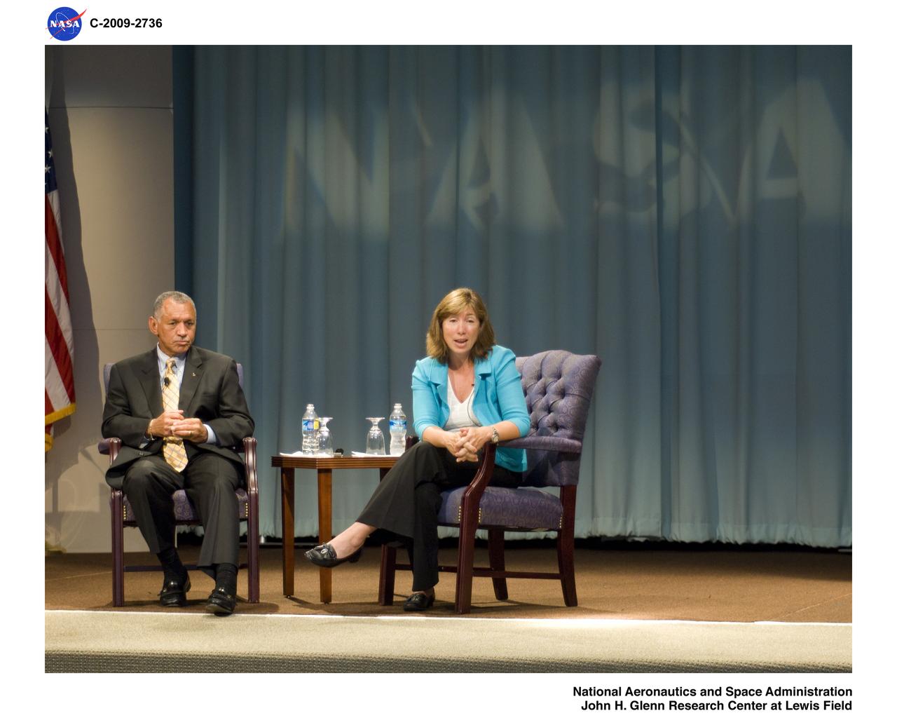
Visit to Glenn Research Center at Lewis Field by NASA Administrator and Deputy Administrator
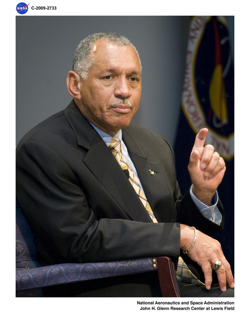
Visit to Glenn Research Center at Lewis Field by NASA Administrator and Deputy Administrator

Visit to Glenn Research Center at Lewis Field by NASA Administrator and Deputy Administrator
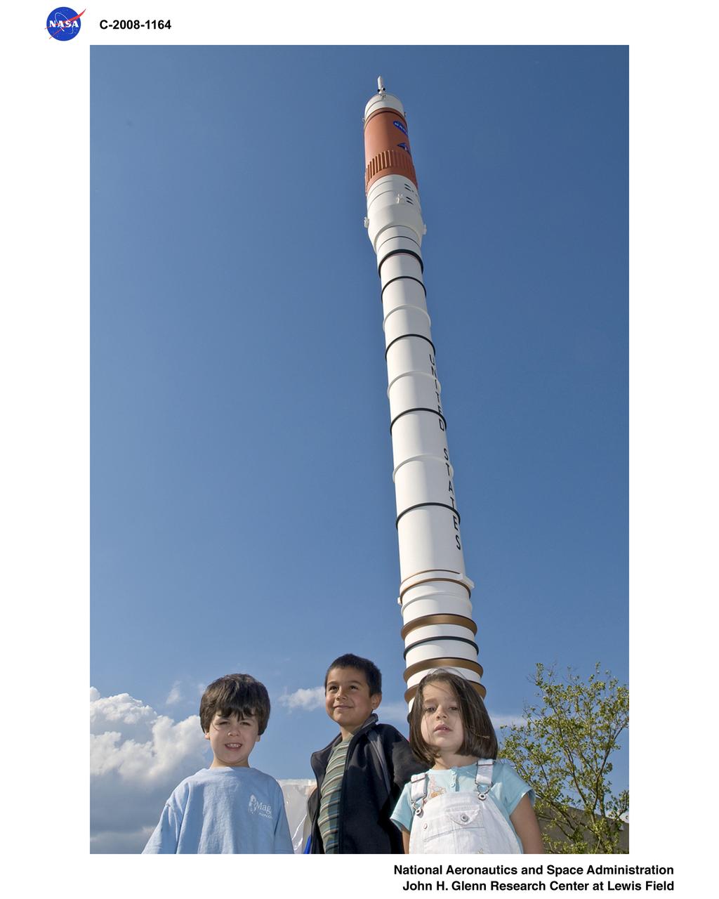
NASA Glenn Research Center at Lewis Field 50th Anniversary Open House

Visit to Glenn Research Center at Lewis Field, GRC, by Astronaut Steve Swanson
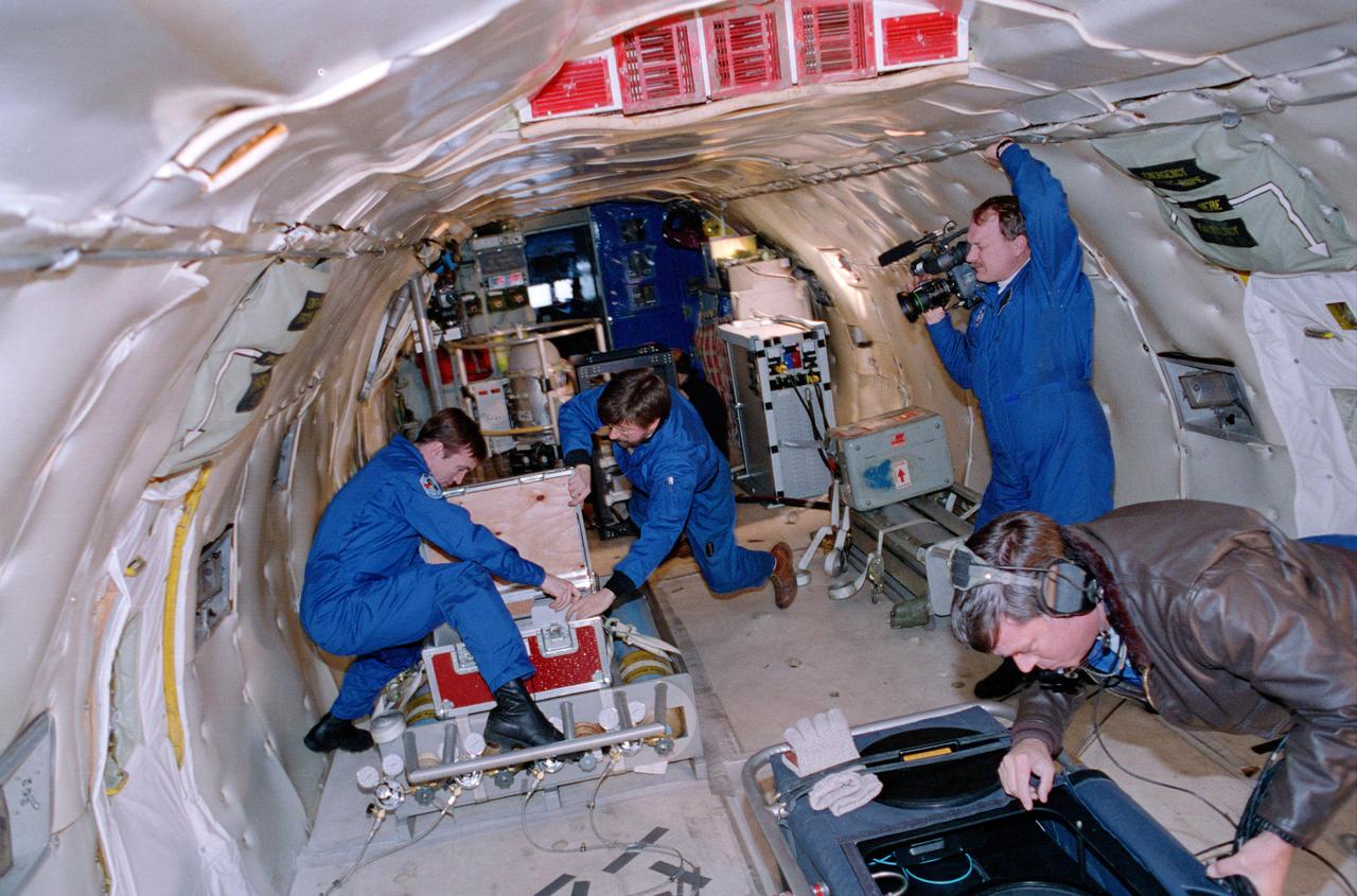
ZERO GRAVITY AIRCRAFT KC135 FLIGHTS AT LEWIS RESEARCH CENTER
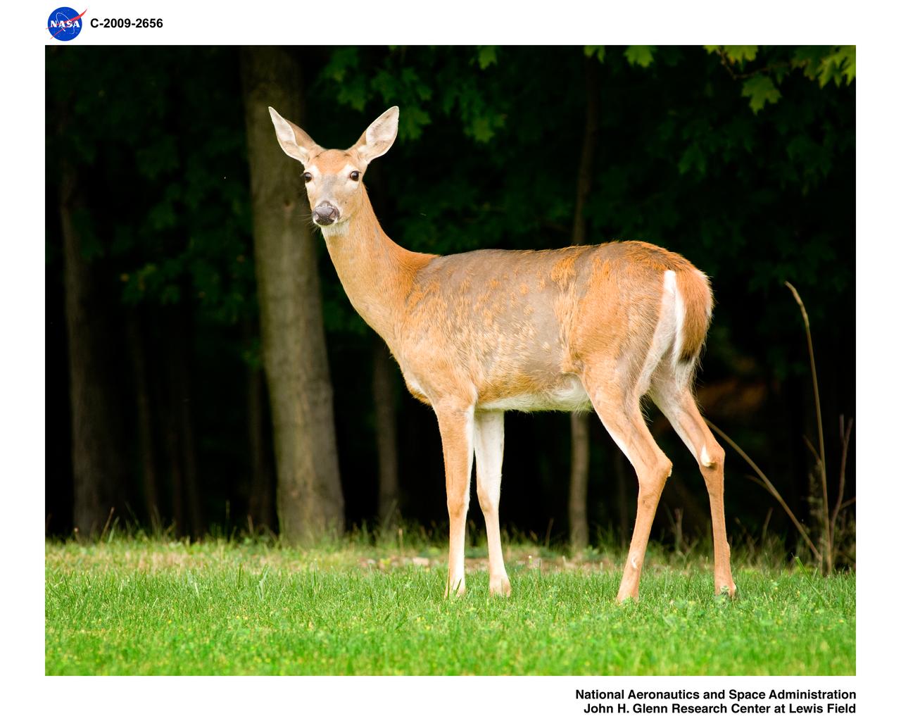
Deer in West Area, Glenn Research Center at Lewis Field
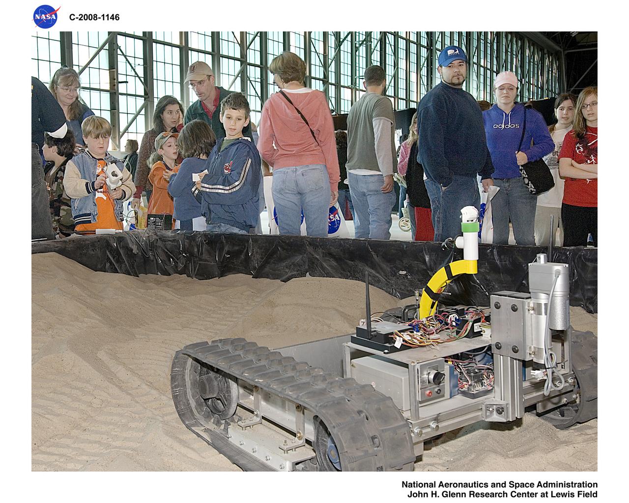
NASA Glenn Research Center at Lewis Field 50th Anniversary Open House
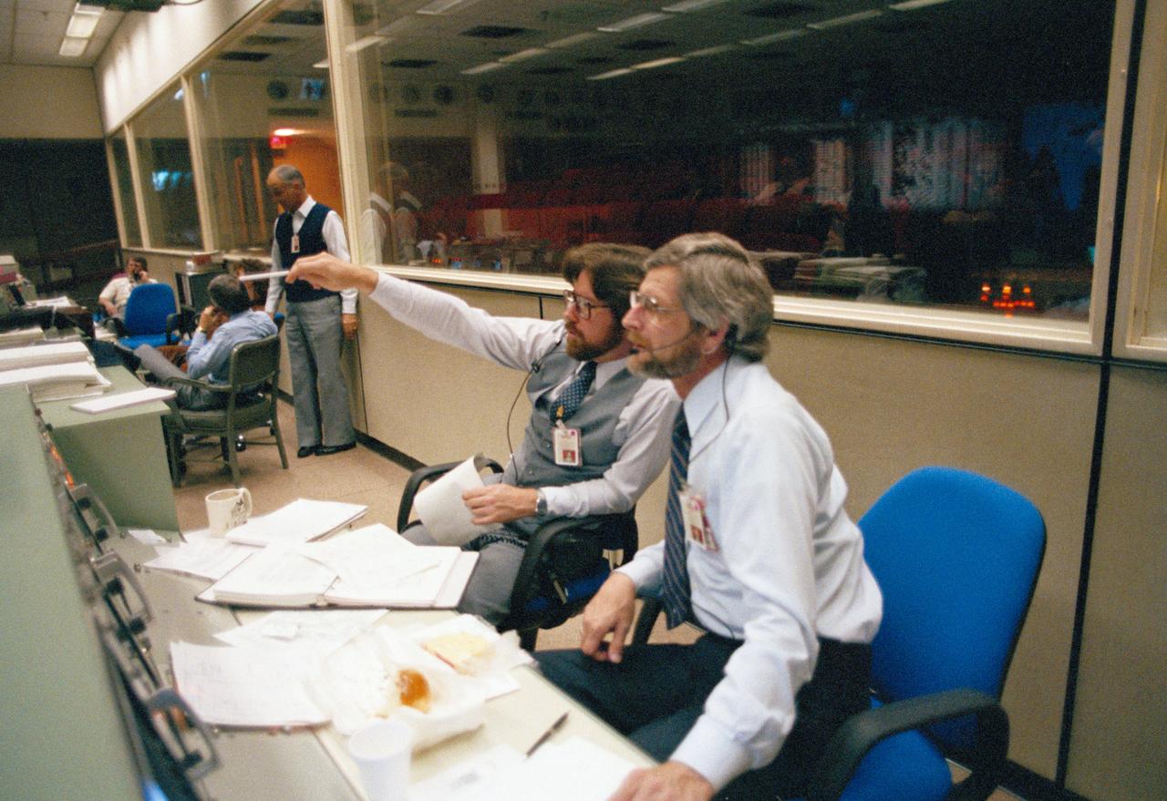
s83-46015 Views of the Mission Control Center activity of Eidophor with STS-9 Landing Data; PAO Console ith Steve Nesbitt and Harold S. Stall; FD Console with Charles Lewis and Ralph Hoodless, Lewis and M.P. "Pete" Frank; and the hanging of the STS-9 Plaque
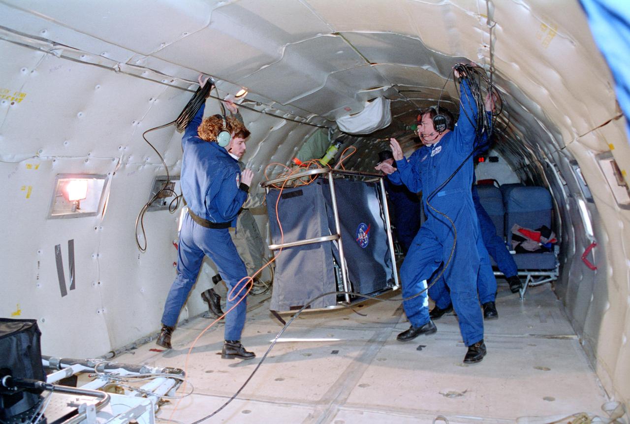
ZERO GRAVITY AIRCRAFT KC135 FLIGHTS AT LEWIS RESEARCH CENTER (Glenn Research Center)

The sign near the entrance of the National Advisory Committee for Aeronautics (NACA) Flight Propulsion Research Laboratory. The name was changed several weeks later to the Lewis Flight Propulsion Laboratory in honor of the NACA’s former Director of Aeronautical Research, George W. Lewis. The research laboratory has had five different names since its inception in 1941. The Cleveland laboratory was originally known as the NACA Aircraft Engine Research Laboratory. In 1947 it was renamed the NACA Flight Propulsion Research Laboratory to reflect the expansion of the research activities beyond just engines. Following the death of George Lewis, the name was changed to the NACA Lewis Flight Propulsion Laboratory in September 1948. On October 1, 1958, the lab was incorporated into the new NASA space agency, and it was renamed the NASA Lewis Research Center. Following John Glenn’s flight on the space shuttle, the name was changed again to the NASA Glenn Research Center on March 1, 1999. From his office in Washington DC, George Lewis managed the aeronautical research conducted at the NACA for over 20 years. His most important accomplishment, however, may have been an investigative tour of German research facilities in the fall of 1936. The visit resulted in the broadening of the scope of the NACA’s research and the physical expansion that included the new engine laboratory in Cleveland.
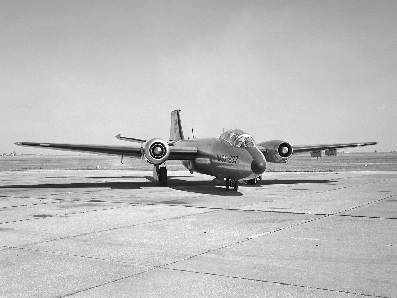
A Martin B-57B Canberra outfitted with a noise suppressor on its right engine at the National Aeronautics and Space Administration (NASA) Lewis Research Center. The aircraft was being prepared for the October 1966 Inspection of the center. The Inspection also marked Lewis’ twentieth anniversary. Lewis researchers had been studying engine noise for almost a decade, but the problem seemed to be increasing in the mid-1960s with heavier airline traffic and larger engines. Researchers discovered early on that the majority of the noise did not emanate from the engine itself, but from the mixing of the hot exhaust gasses with the atmosphere. Attempts to reduce the turbulence using new exhaust nozzles were successful but often resulted in decreased engine performance. The researchers decided to try to lower the jet nozzle exit velocity without decreasing its thrust. The inlet mass air flow had to be increased to accomplish this. The Lewis B-57B was powered by two Wright Aeronautical J65 turbojets. Lewis engineers modified the stators on the two engines to simulate the noise levels from more-modern turbofan engines. A noise suppressor was added to only one of the two engines, seen here on the left. The engines were run one at a time at power levels similar to landing while the aircraft sat on the Lewis hangar apron. A microphone and recording equipment was setup to capture the noise levels. The engine with the suppressor produced 13 fewer decibels than the standard engine.

Mercury astronaut John Glenn prepares for a test in the Multi-Axis Space Test Inertia Facility (MASTIF) inside the Altitude Wind Tunnel at the National Aeronautics and Space Administration (NASA) Lewis Research Center. The MASTIF was a three-axis test rig with a pilot’s chair mounted in the center. The device was designed to train Project Mercury pilots to bring a spinning spacecraft under control. An astronaut was secured in a foam couch in the center of the rig. The rig was then spun on three axes from 2 to 50 rotations per minute. Small nitrogen gas thrusters were used by the astronauts to bring the MASTIF under control. In February and March 1960, the seven Project Mercury astronauts traveled to Cleveland to train on the MASTIF. Warren North and a team of air force physicians were on hand to monitor their health. After being briefed by Lewis pilot Joe Algranti and researcher James Useller, the rider would climb into the rig and be secured in the chair, as seen in this photograph. A Lewis engineer would then slowly set the MASTIF in motion. It was the astronaut’s job to bring it under control. Each individual was required to accumulate 4.5 to 5 hours of MASTIF time. Glenn became the first American to orbit the earth on February 20, 1962 in the Friendship 7 Mercury capsule. In March 1999, the Lewis Research Center was renamed the John H. Glenn Research Center at Lewis Field.
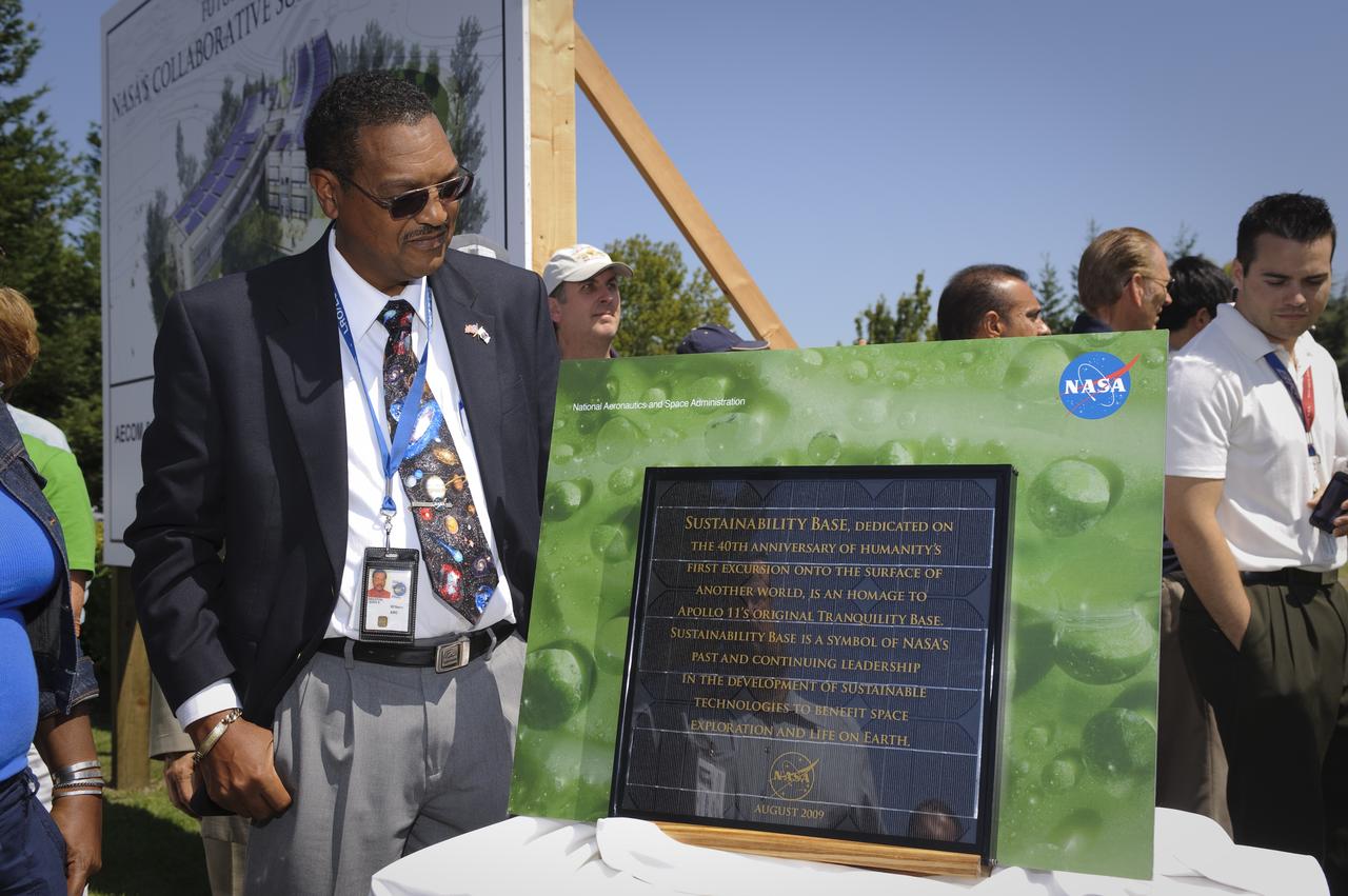
Sustainability Base Ground Breaking ceremony Lewis Braxton III, Deputy Director Ames Research Center with dedication plaque
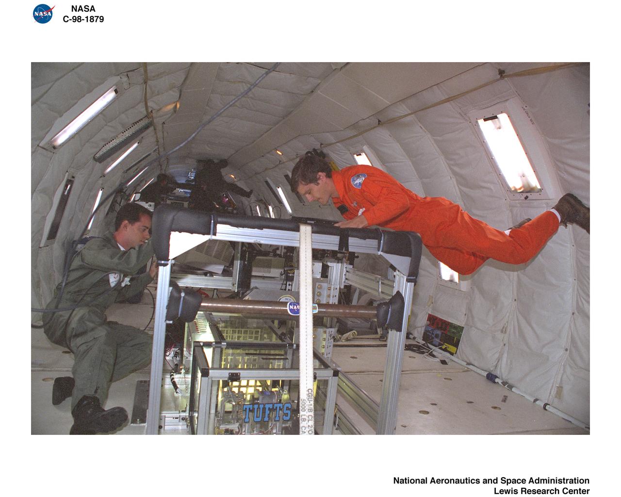
KC-135 AIRPLANE FLIGHT AT LEWIS RESEARCH CENTER DURING WEEK OF AUGUST 17 THROUGH 22 1998
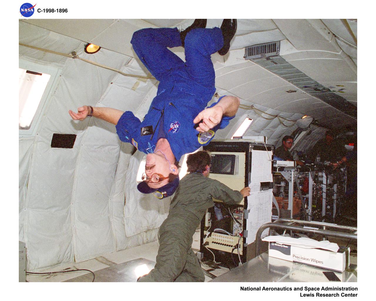
KC-135 AIRPLANE FLIGHT AT LEWIS RESEARCH CENTER DURING WEEK OF AUGUST 17 THROUGH 22 1998
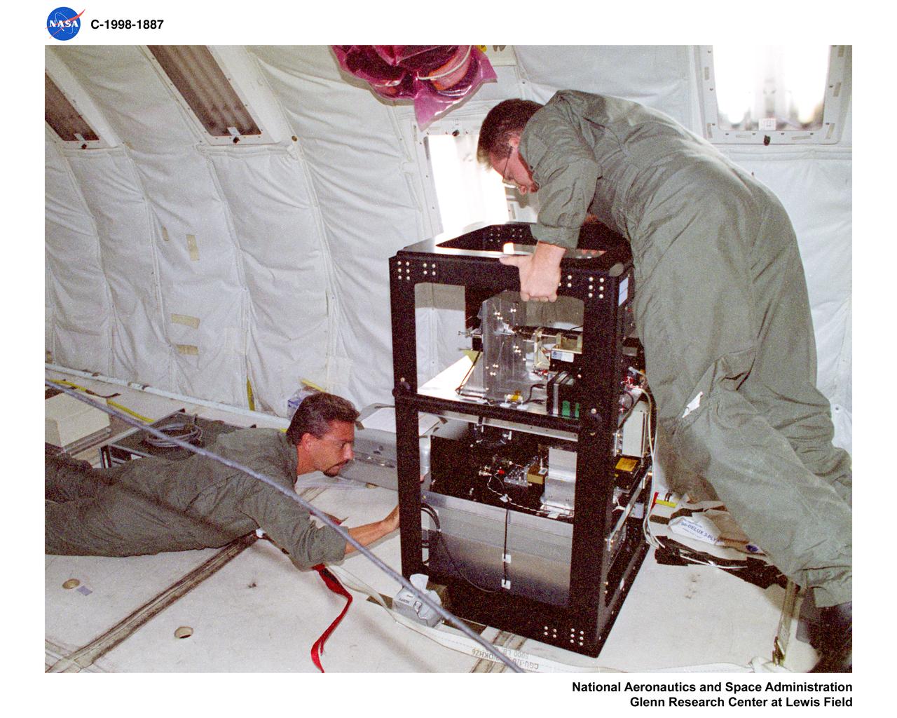
KC-135 AIRPLANE FLIGHT AT LEWIS RESEARCH CENTER DURING WEEK OF AUGUST 17 THROUGH 22 1998
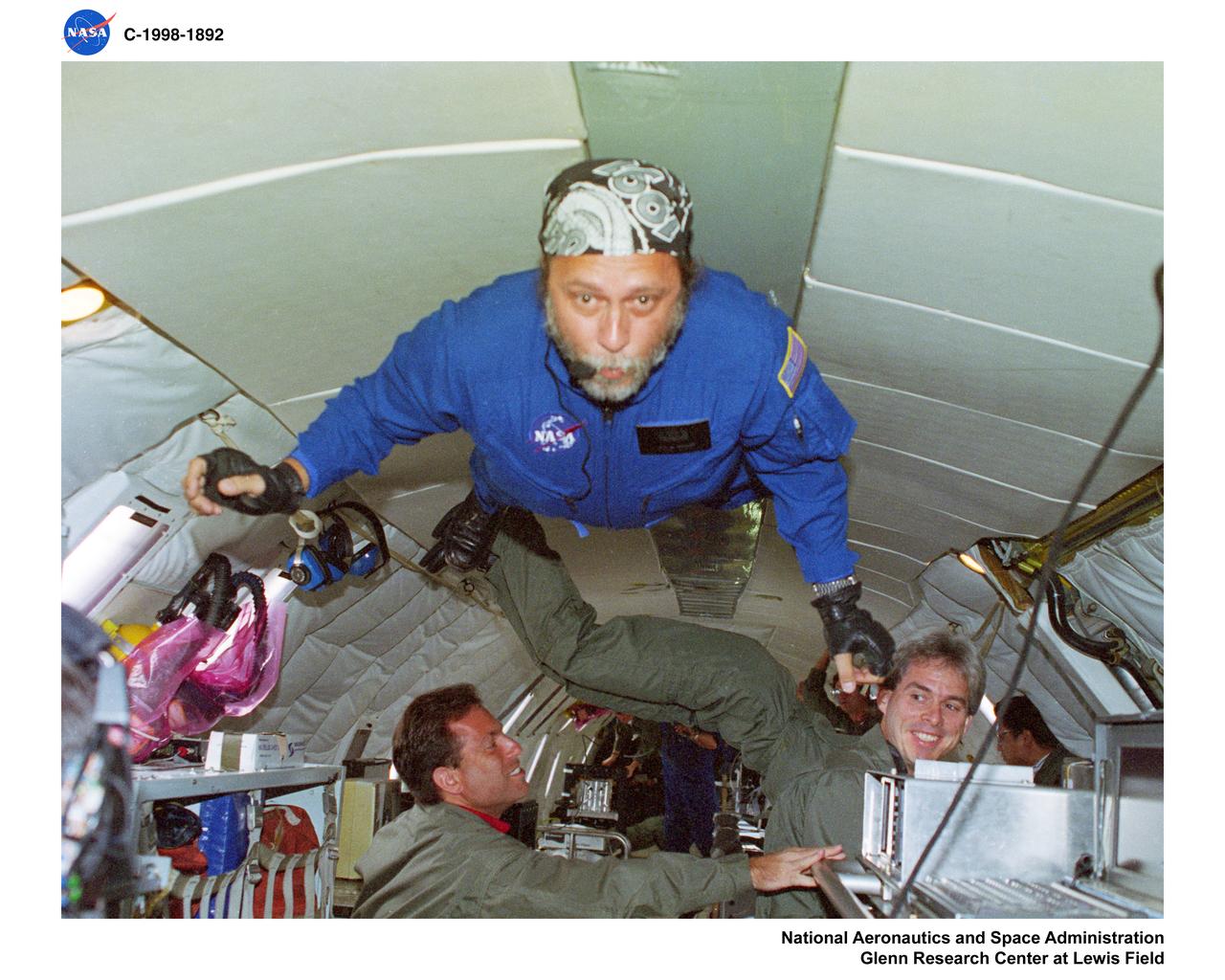
KC-135 AIRPLANE FLIGHT AT LEWIS RESEARCH CENTER DURING WEEK OF AUGUST 17 THROUGH 22 1998
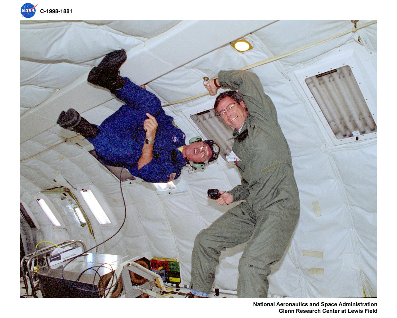
KC-135 AIRPLANE FLIGHT AT LEWIS RESEARCH CENTER DURING WEEK OF AUGUST 17 THROUGH 22 1998
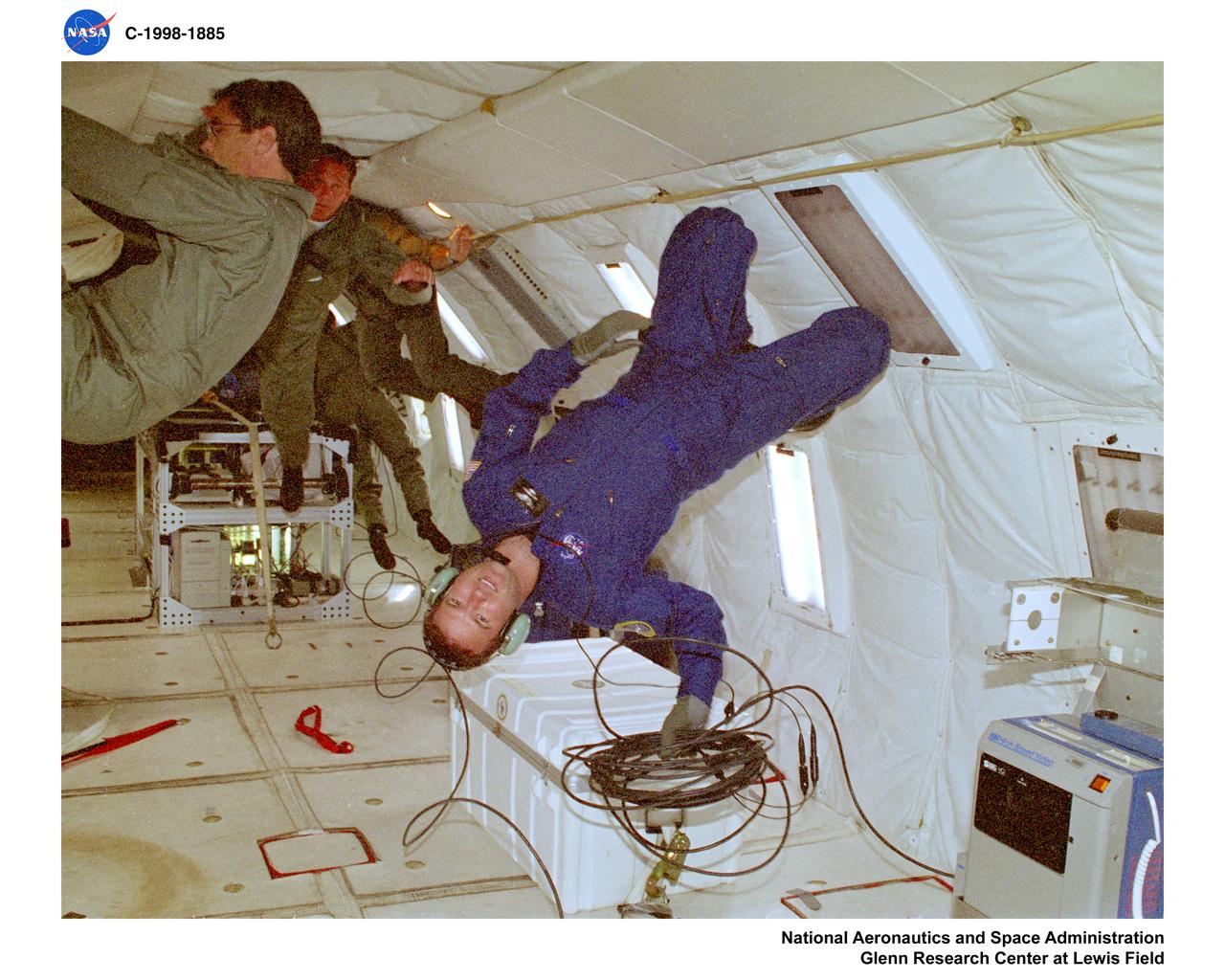
KC-135 AIRPLANE FLIGHT AT LEWIS RESEARCH CENTER DURING WEEK OF AUGUST 17 THROUGH 22 1998
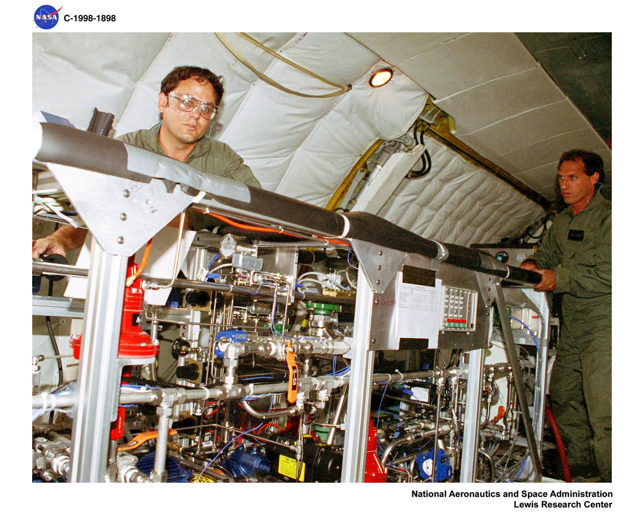
KC-135 AIRPLANE FLIGHT AT LEWIS RESEARCH CENTER DURING WEEK OF AUGUST 17 THROUGH 22 1998
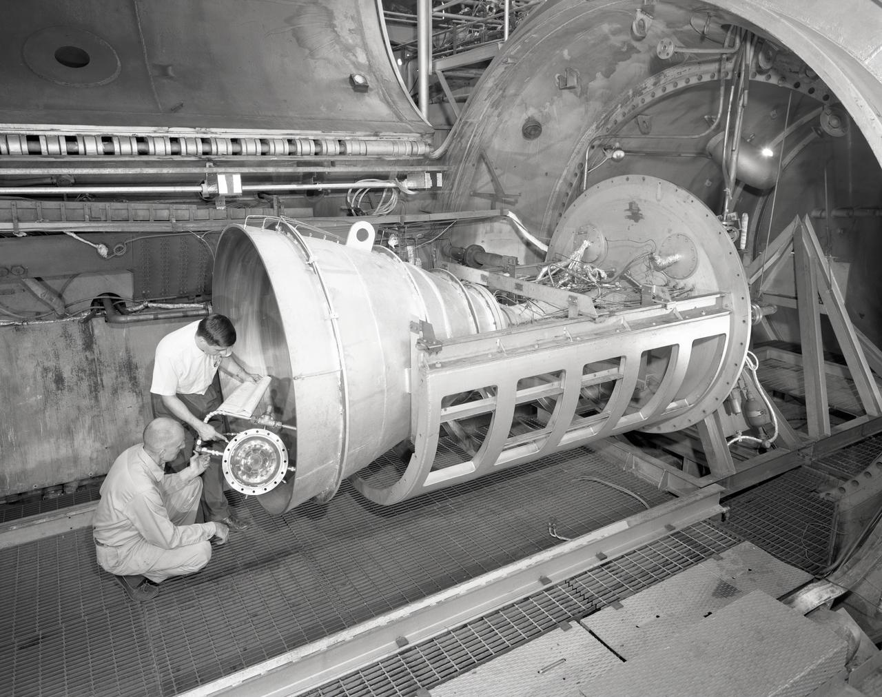
Apollo Contour Engine Model being tested in the NASA Lewis Research Center, Propulsion Systems Laboratory, PSL
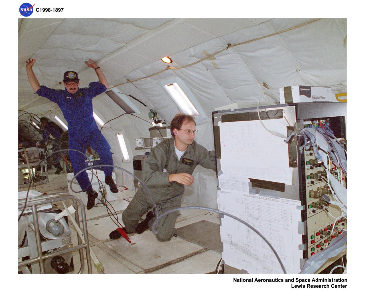
KC-135 AIRPLANE FLIGHT AT LEWIS RESEARCH CENTER DURING WEEK OF AUGUST 17 THROUGH 22 1998
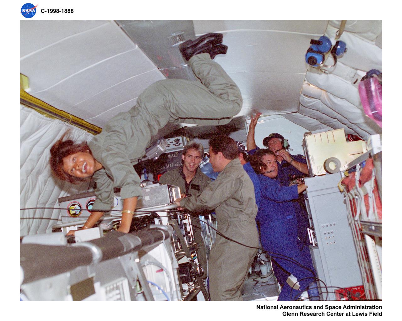
KC-135 AIRPLANE FLIGHT AT LEWIS RESEARCH CENTER DURING WEEK OF AUGUST 17 THROUGH 22 1998
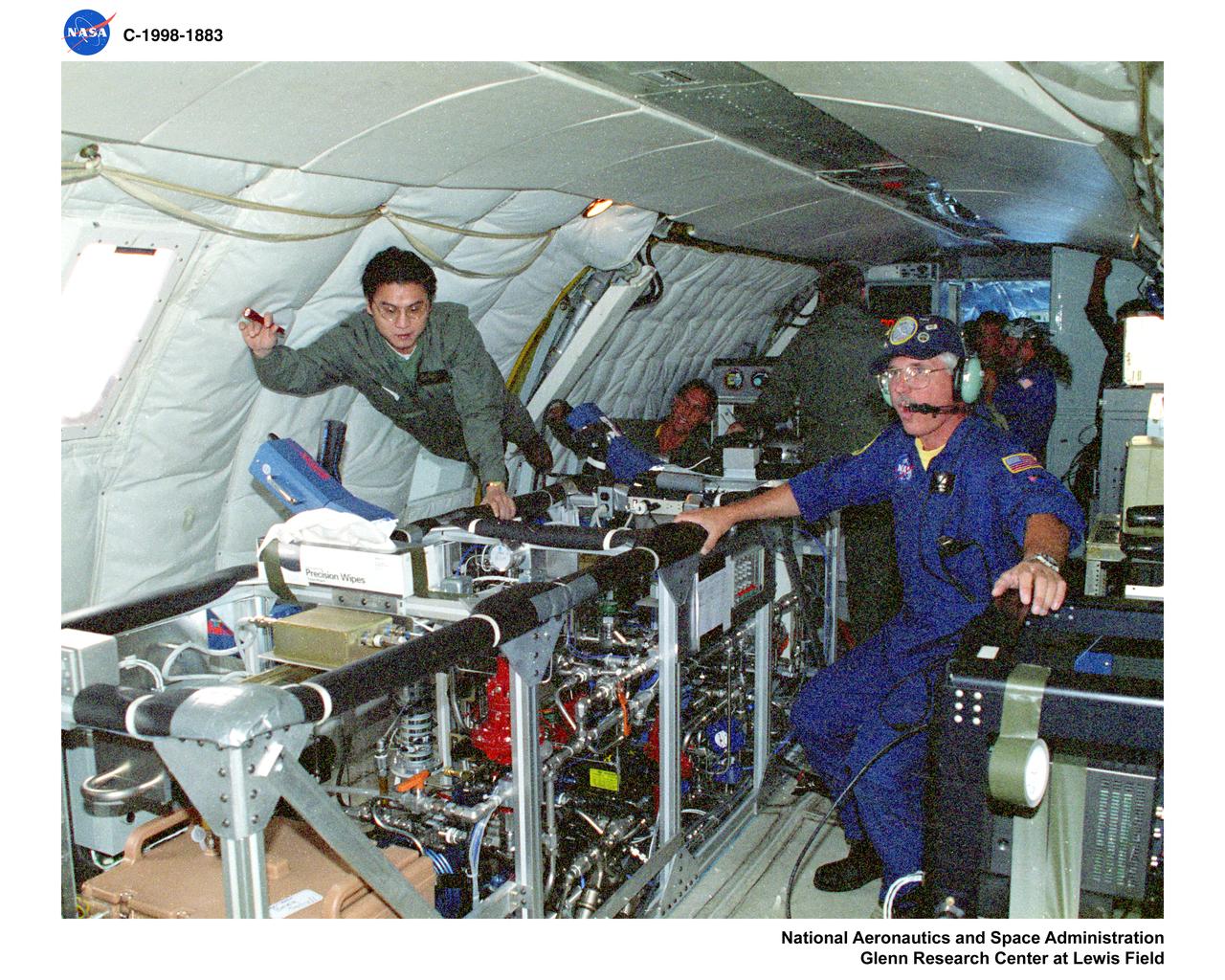
KC-135 AIRPLANE FLIGHT AT LEWIS RESEARCH CENTER DURING WEEK OF AUGUST 17 THROUGH 22 1998
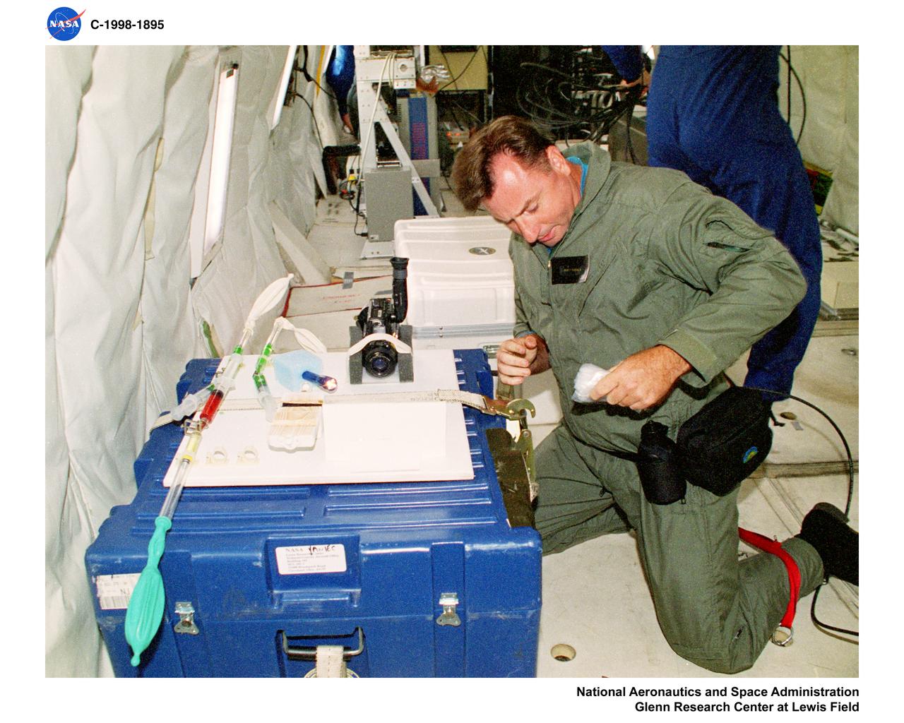
KC-135 AIRPLANE FLIGHT AT LEWIS RESEARCH CENTER DURING WEEK OF AUGUST 17 THROUGH 22 1998
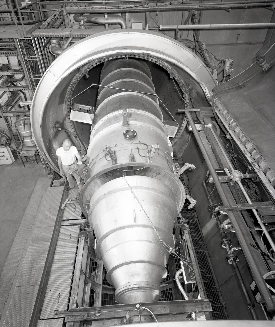
Apollo Contour Engine Model being tested in the NASA Lewis Research Center, Propulsion Systems Laboratory, PSL
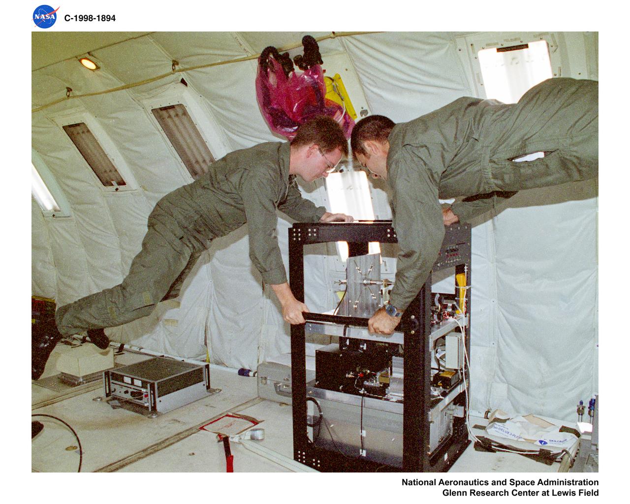
KC-135 AIRPLANE FLIGHT AT LEWIS RESEARCH CENTER DURING WEEK OF AUGUST 17 THROUGH 22 1998
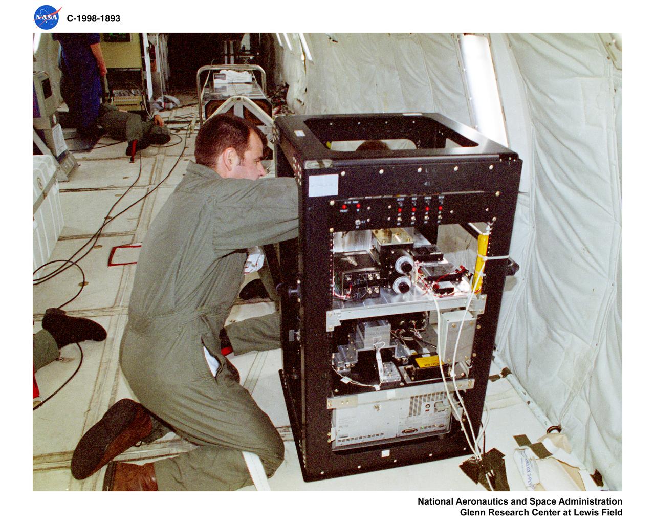
KC-135 AIRPLANE FLIGHT AT LEWIS RESEARCH CENTER DURING WEEK OF AUGUST 17 THROUGH 22 1998
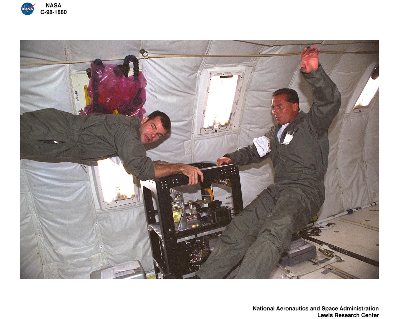
KC-135 AIRPLANE FLIGHT AT LEWIS RESEARCH CENTER DURING WEEK OF AUGUST 17 THROUGH 22 1998
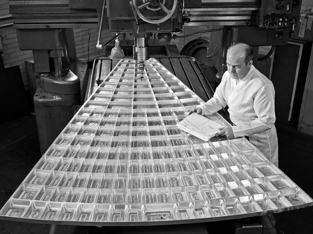
Daniel Bernatowicz, Chief of the Advanced Power Systems Branch at the National Aeronautics and Space Administration (NASA) Lewis Research Center, examines a 20-foot section of a solar mirror being fabricated in the Jig Bore Room of the Technical Services Building. NASA Lewis was conducting a wide-ranging effort to explore methods of generating electrical power for spacecraft. One method employed a large parabolic mirror to concentrate the sun’s energy. The mirror had to remain rigid and withstand micrometeoroids, but remain light and compact enough to be easily launched. In 1963 Bernatowicz and his researchers undertook a program to design a solar mirror to work with the Brayton cycle system on a space station. The mirror in this photograph was prepared for a conference on Advanced Technology in Space Power Systems held at Lewis in late August 1966. Lewis experts discussed advances with batteries, fuel cells, isotope and thermoelectric generators, and the SNAP-8 space power system. Lewis was developing several types of solar mirrors to work with a Brayton cycle electric generating system. The mirror’s 12 sections were shaped using a unique forming process developed at Lewis, coated with an epoxy, and plated with aluminum. The mirror concentrated the Sun's rays on a heat storage receiver containing lithium fluoride. This material was heated to produce power in a turbogenerator system, while additional heat was stored for use when the unit was in the Earth's shadow.
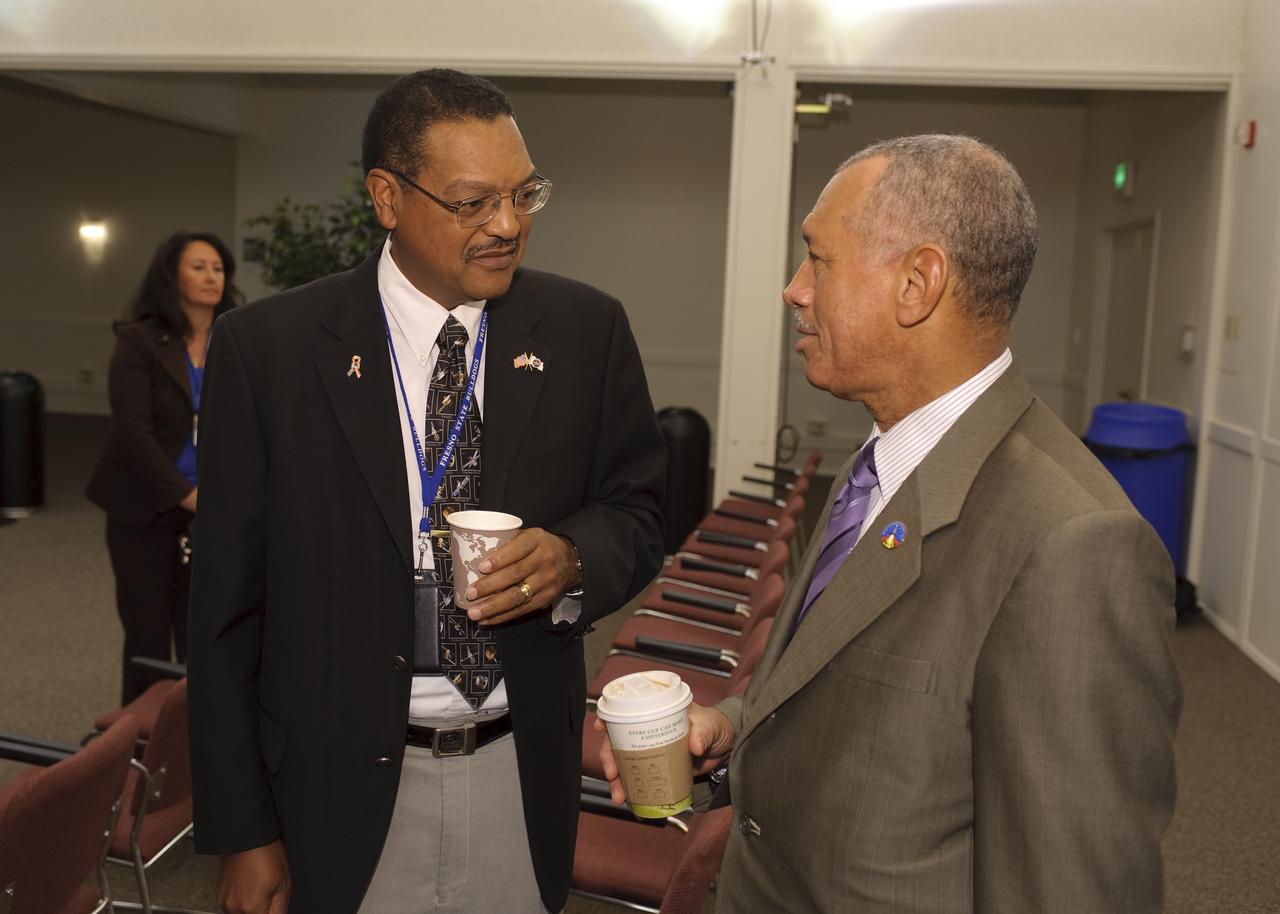
NASA Advisory Council Meeting at NASA Ames Research Center NRP Conference Center. Lewis Braxton, III (left) Charile Bolden, NASA Administrator
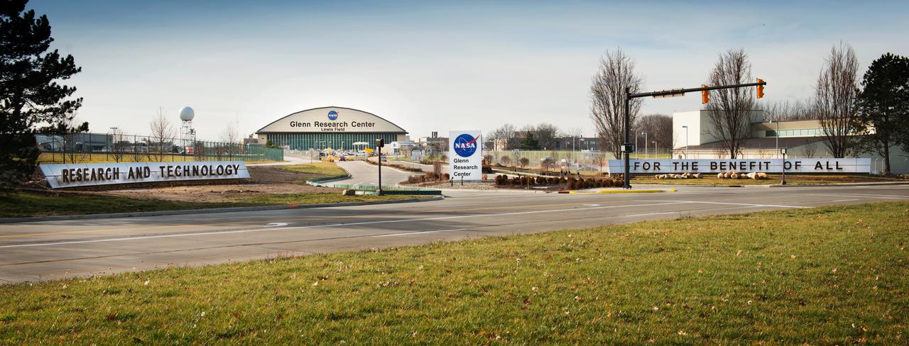
Main Entrance of NASA Glenn Research Center at Brookpark Road and NASA Parkway. The signs read: Research and Technology For The Benefit Of All.
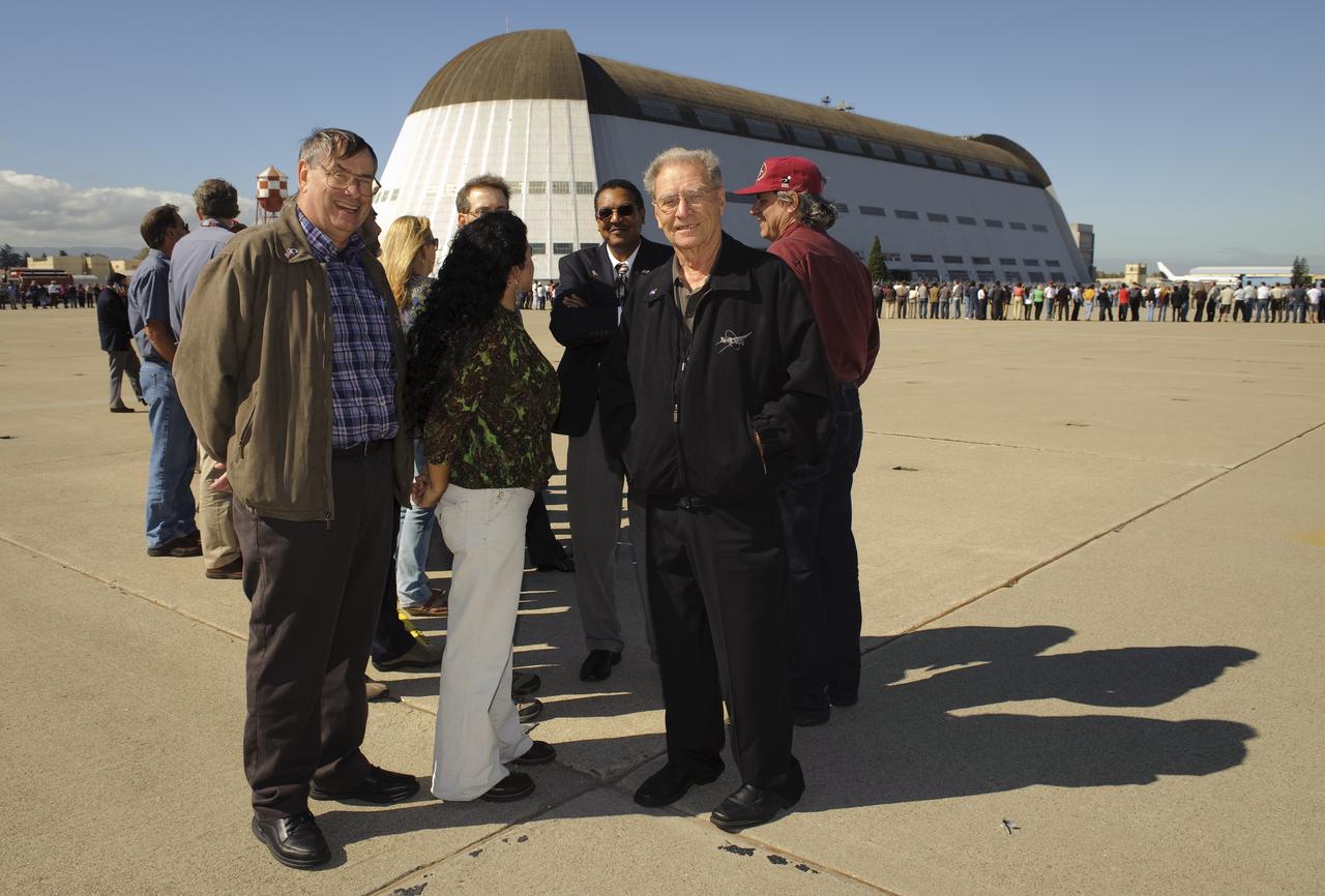
Ames 70_year picture day on Flight line. Center Director S. Pete Worden, Jack Boyd, Lewis Braxton, III start the line on the seven.
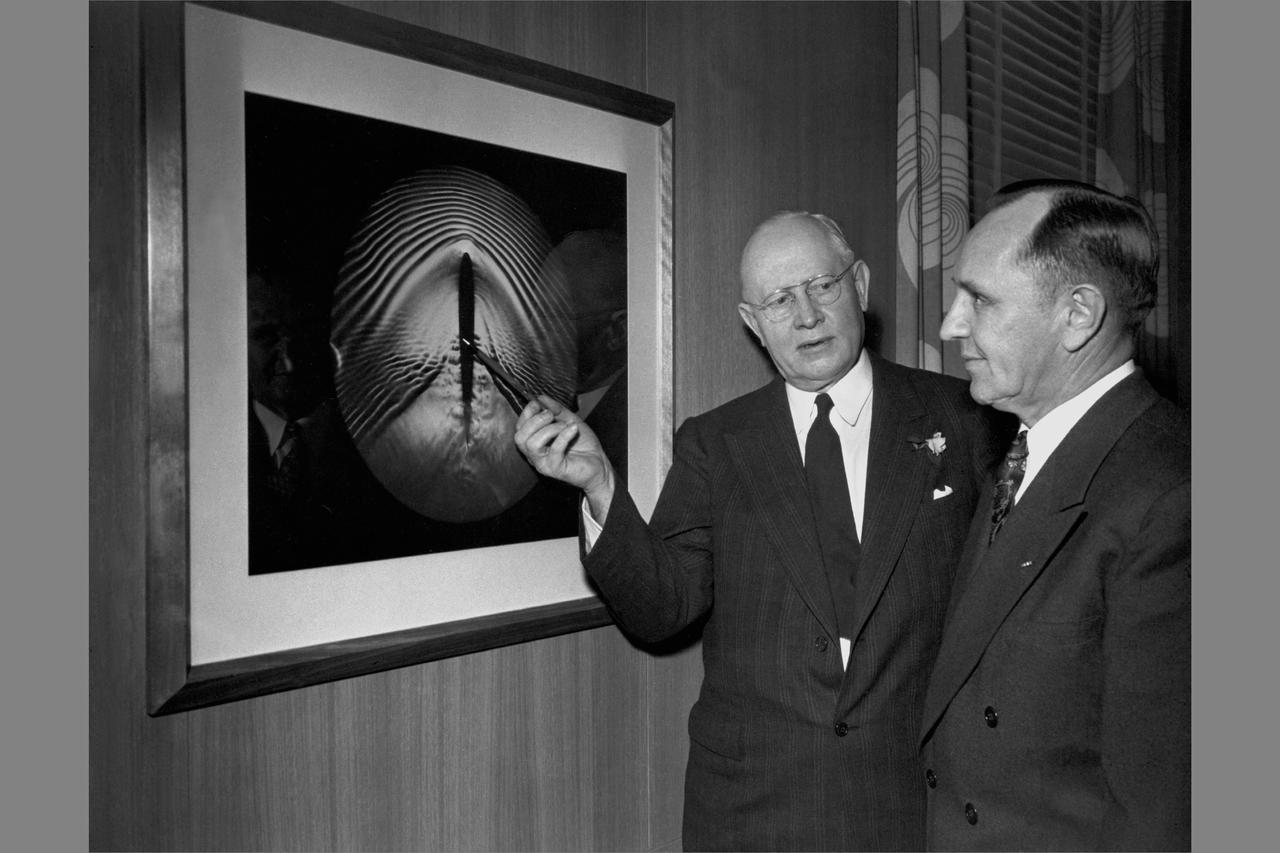
Ames Aeronautica Laboratory Dedication ceremonies; Dr. Lewis and Smity DeFrance, Director, Ames Research Center standing in front of shock-wave picture.
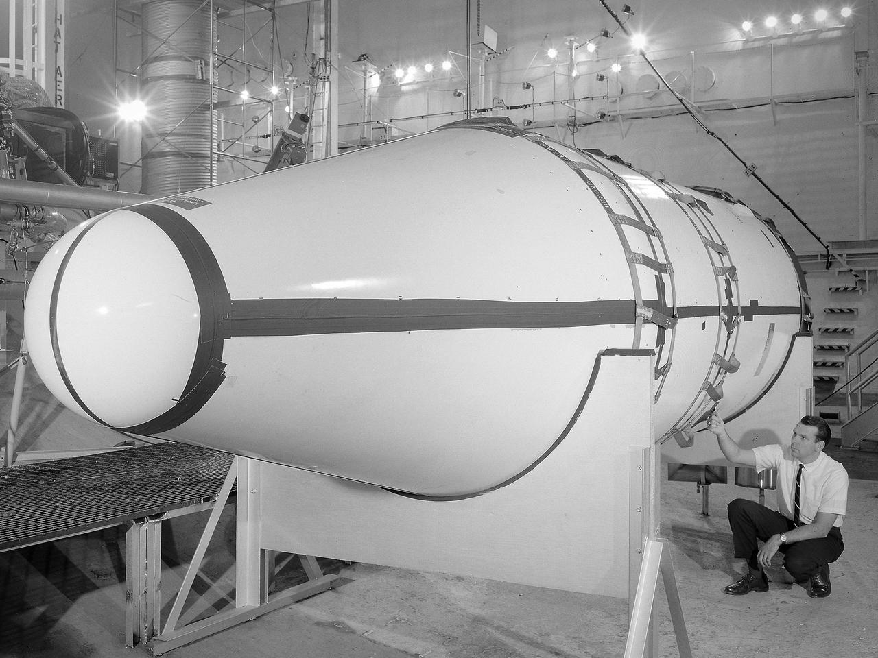
Setup of a Surveyor/Atlas/Centaur shroud in the Space Power Chambers for a leak test at the National Aeronautics and Space Administration (NASA) Lewis Research Center. Centaur was a 15,000-pound thrust second-stage rocket designed for the military in 1957 and 1958 by General Dynamics. It was the first major rocket to use the liquid hydrogen technology developed by Lewis in the 1950s. The Centaur Program suffered numerous problems before being transferred to Lewis in 1962. Several test facilities at Lewis’ main campus and Plum Brook Station were built or modified specifically for Centaur, including the Space Power Chambers. In 1961, NASA Lewis management decided to convert its Altitude Wind Tunnel into two large test chambers and later renamed it the Space Power Chambers. The conversion, which took over 2 years, included the removal of the tunnel’s internal components and insertion of bulkheads to seal off the new chambers. The larger chamber, seen here, could simulate altitudes of 100,000 feet. It was used for Centaur shroud separation and propellant management studies until the early 1970s. The leak test in this photograph was likely an attempt to verify that the shroud’s honeycomb shell did not seep any of its internal air when the chamber was evacuated to pressures similar to those found in the upper atmosphere.
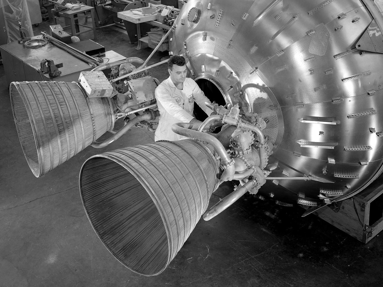
A researcher prepares a Centaur 6A second-stage rocket for a series of tests in the Space Power Chambers’ vacuum tank at the National Aeronautics and Space Administration (NASA) Lewis Research Center. Lewis was assigned oversight of the Centaur Program in the fall of 1962. Prior to that, Centaur’s only launch had failed shortly after liftoff. Lewis engineers undertook an expansive effort to quickly resolve Centaur’s problems and prepare it for its planned missions to send Surveyor spacecraft to land on the moon. For one test program, a complete Centaur vehicle was lowered into the vacuum chamber at the Space Power Chambers to verify that its electronics and electrical systems functioned reliably in a space environment. At the time, electronic malfunctions were one of the most likely causes of failures in space. Studying these systems during long soaks inside the space tank helped the Lewis team calibrate them and facilitate the monitoring of the spacecraft during an actual flight. The Centaur for the tests was delivered to Cleveland in a C-130 aircraft on September 27, 1963. The rocket was set up in the facility’s high bay where Lewis technicians and General Dynamics consultants updated its flight systems to match the upcoming Atlas-Centaur-4 mission, as seen in this photograph.
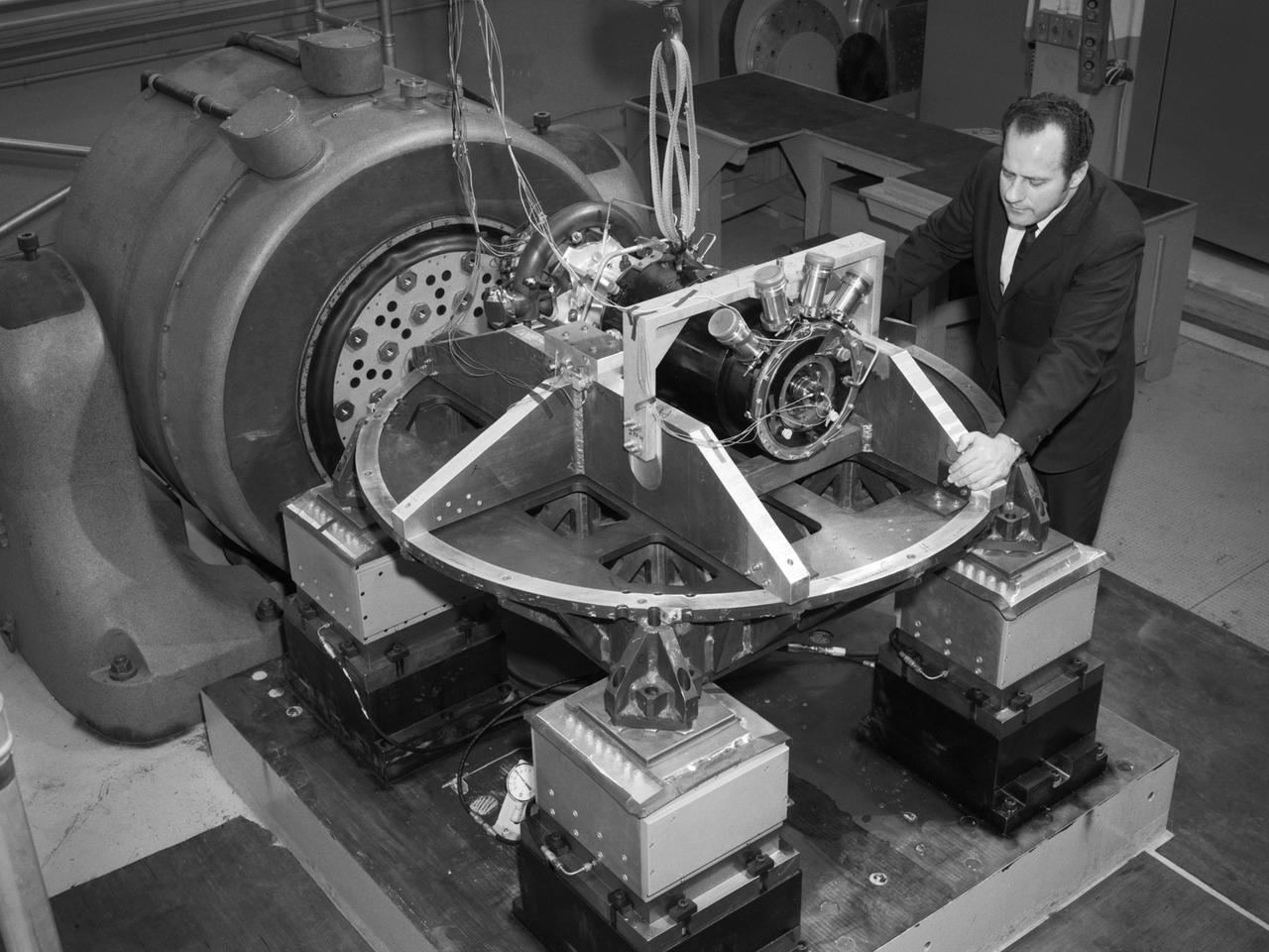
Aeronautics and Space Administration (NASA) Lewis Research Center. Aerojet General was contracted to design the SNAP-8 generator which employed a mercury Rankine system to convert the reactor’s heat into electrical power. The hermetically-sealed pump was designed to generate from 35 to 90 kilowatts of electrical power. In 1964 a SNAP-8 test rig with a mercury boiler and condenser was set up in cell W-1 of Lewis’ Engine Research Building to study the transients in the system’s three loops. In 1967 a complete Rankine system was operated for 60 days in W-1 to verify the integrity of the Lewis-developed mercury boiler. Further tests in 1969 verified the shutdown and startup of the system under normal and emergency conditions. Aerojet operated the first full-Rankine system in June 1966 and completed a 2500-hour endurance test in early 1969. Lewis and Aerojet’s success on the Rankine system was acknowledged with NASA Group Achievement Award in November 1970. The 1970 vibration tests, seen here, were conducted in Lewis’ Engine Research Building’s environmental laboratory. The testing replicated the shock and vibration expected to occur during the launch into space and subsequent maneuvering. The pump was analyzed on each of its major axes.

The National Aeronautics and Space Administration (NASA) Lewis Research Center acquired this Gulfstream C-131B Samaritan from the Air Force in July 1976. The center obtained the aircraft to support its current earth resources work. The C-131B is seen here inside the Lewis hangar being refurbished and converted into a flying laboratory. The modifications were led by Lewis Chief of Flight Operations Robert Hogan. The cockpit and cabin were modified and packed with instrumentation. The new equipment included Sideways Looking Airborne Radar (SLAR), geothermal sensors, radar antennas, and an inertial navigation system. In addition, portals were installed underneath the fuselage for cameras and remote sensing equipment. NASA’s C-131B was used to support researchers tracking ice flows on the Great Lakes and in Prudhoe Bay, Alaska. It was also used for the center’s program to determine heating losses in the Cleveland area’s residential and commercial structures. The aircraft was later donated to the University of Georgia.
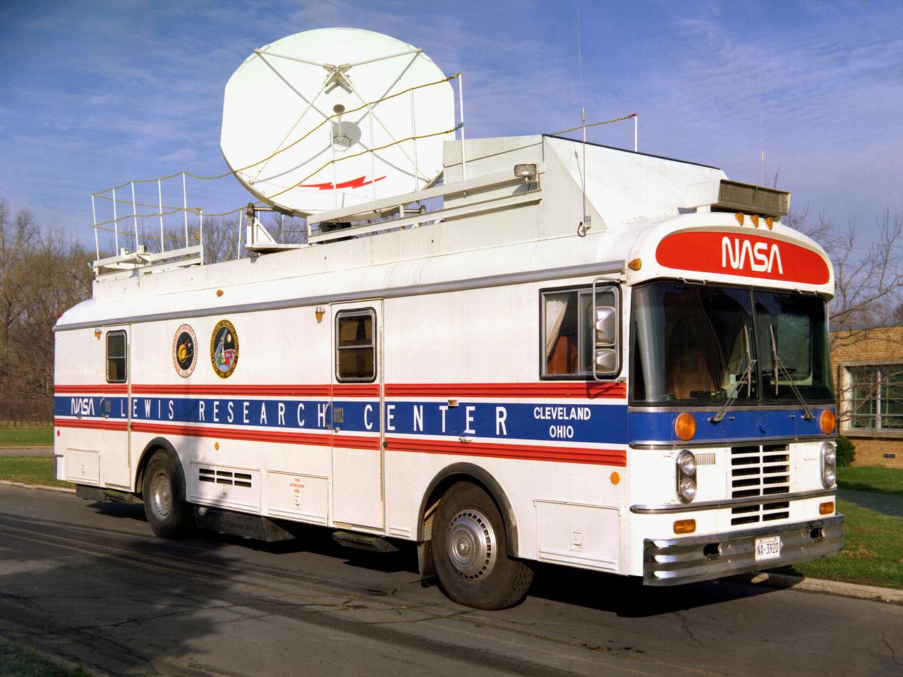
This vehicle served as a mobile terminal for the Communications Technology Satellite. The Communications Technology Satellite was an experimental communications satellite launched in January 1976 by the National Aeronautics and Space Administration (NASA) and the Canadian Department of Communications. The satellite operated in a new frequency band reserved for broadcast satellites with transmitting power levels that were 10 to 20 times higher than those of contemporary satellites. Throughout 1977 and 1978 NASA allowed qualified groups to utilize the satellite from one of the three ground-based transmission centers. NASA’s Lewis Research Center in Cleveland, Ohio was NASA’s lead center on the project. Lewis was responsible for the control and coordination of all US experiments on the satellite. The center housed the satellite’s main control center which included eight parabolic reflector antennae ranging from 2 to 15 feet in diameter. Many of the satellite’s components had been tested in simulated space conditions at Lewis. The Lewis-designed vehicle seen here served as a field unit for transmitting and receiving wideband signals and narrowband voice. The vehicle permitted live television interviews, recording equipment, and cameras. An 8-foot diameter parabolic reflector was mounted on the roof. The interior of the vehicle had workstations, monitors, transmitting equipment, and a lounge area.
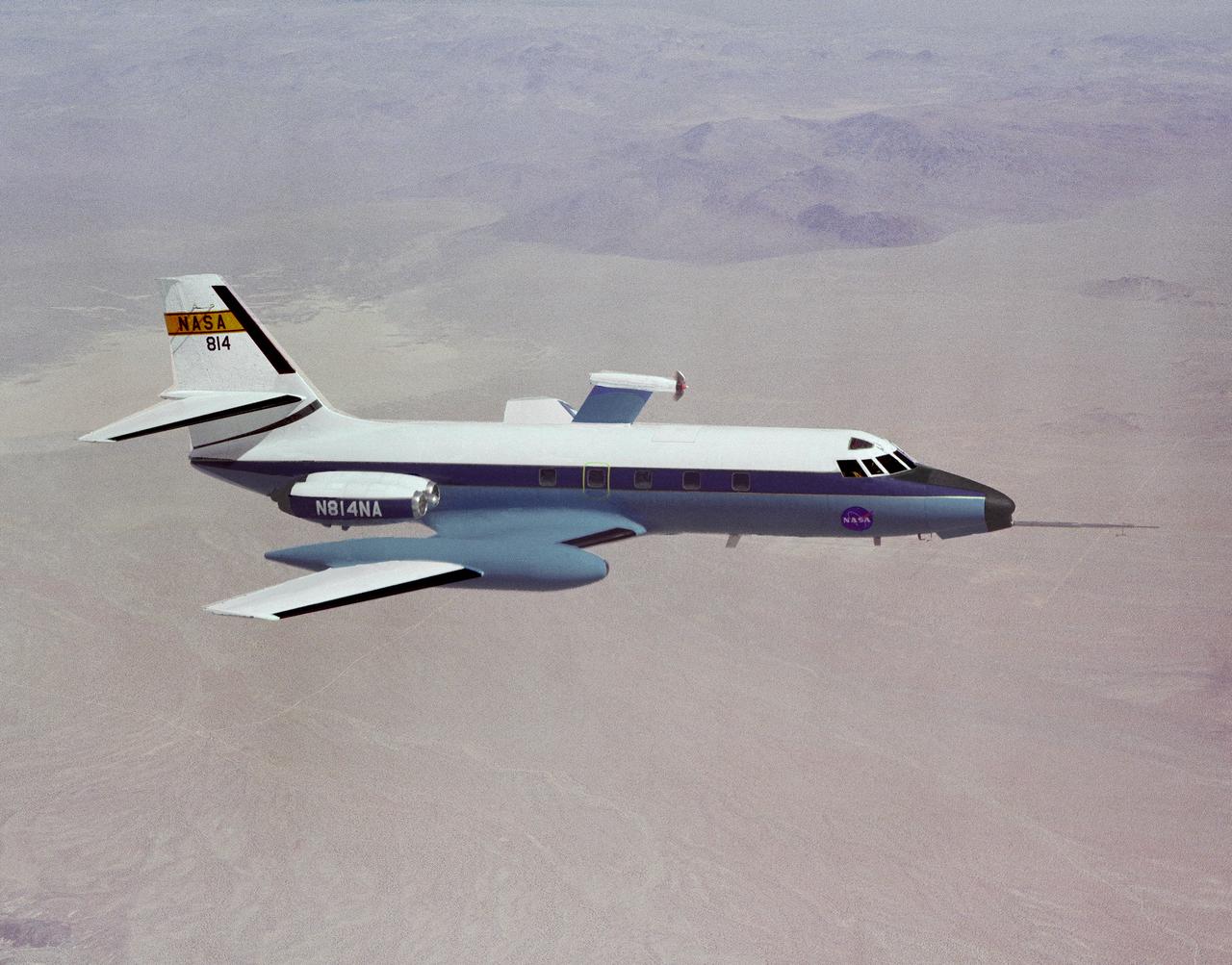
In this photograph, the C-140 JetStar is fitted with a model of a high-speed propeller. Three different designs were tested at NASA's Dryden Flight Research Facility in 1981-1982. Their swept-back blades were intended to increase the speed and fuel efficiency of turboprop aircraft. Speeds of Mach 0.8 were thought possible, while using 20 to 30 percent less fuel than standard jet engines.
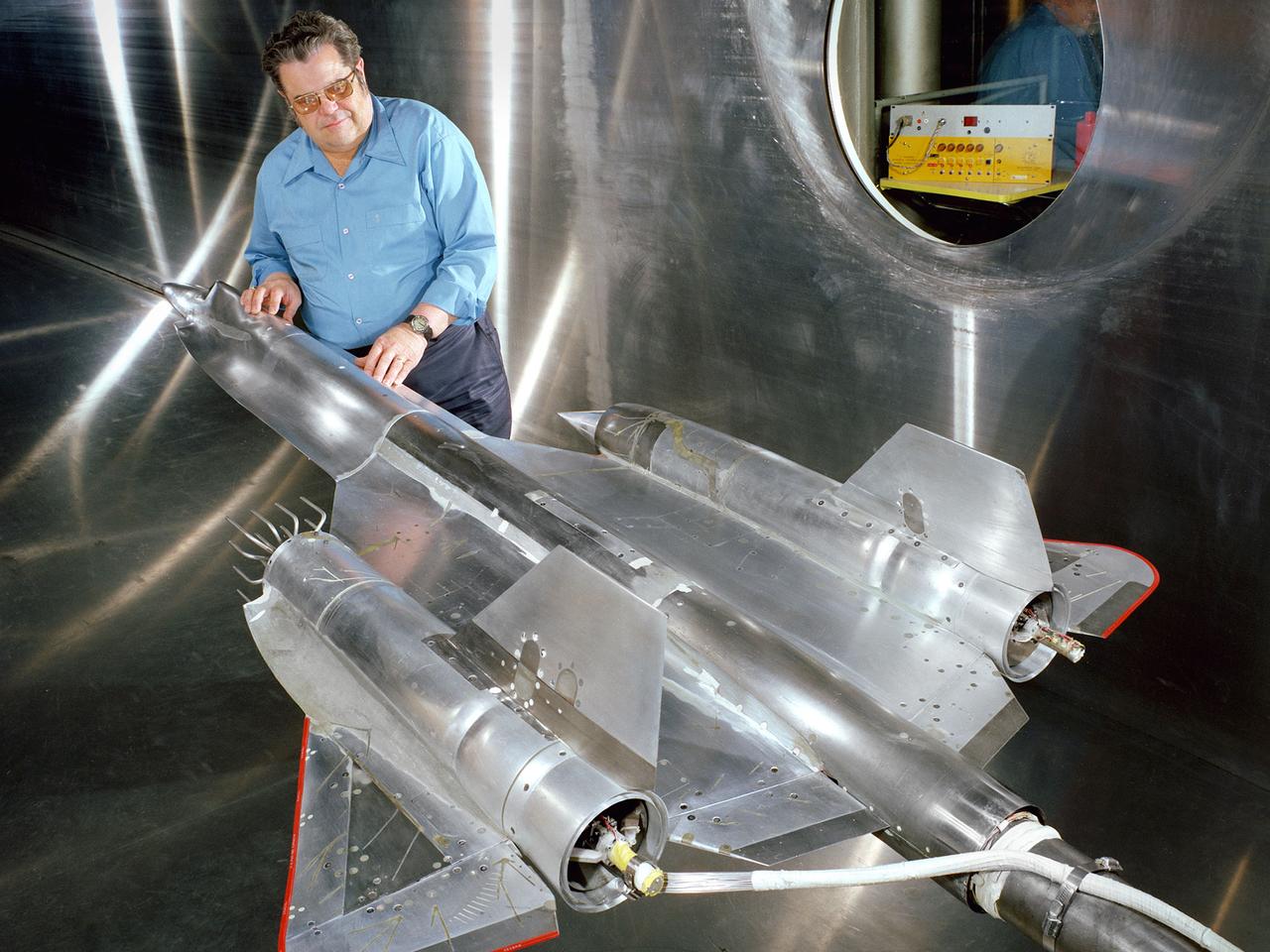
Robert Cubbison examines a model of the Lockheed YF-12 Blackbird in the test section of the 10- by 10-Foot Supersonic Wind Tunnel at the National Aeronautics and Space Administration (NASA) Lewis Research Center. The YF-12 was an experimental fighter version of Lockheed’s A-12 reconnaissance aircraft which had been developed into the renowned SR-71 Blackbird. NASA possessed two YF-12s at its Dryden Flight Research Center which could be used by researchers at all the NASA centers. During its nine-year life, the Dryden’s YF-12 research program logged 297 flights with approximately 450 flight hours. Lewis researchers were studying the YF-12’s inlet airflow in the 10- by 10-foot wind tunnel in late 1977. The advanced supersonic cruise aircraft of the time used mixed-compression inlets. These types of inlets were prone to flameout during atmospheric disturbances. Researchers at Lewis and Dryden developed a program to study these flameouts by artificially introducing flow disturbances. Testing at Dryden with a specially-equipped YF-12 aircraft yielded limited results. Lewis’ tests in the 10- by 10 were unsuccessful at inducing upstream disturbances. The researchers used two methods—a falling plate and a servo-driven wing.
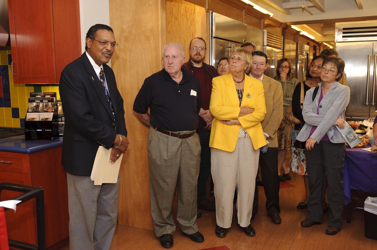
Ames 70 Year Anniversary Exhibit in downtown Mountain View, California. Grand Opening at Meyer Appliance, Castro Street. Lewis Braxton III, Ames Deputy Center Director opens exhibit.
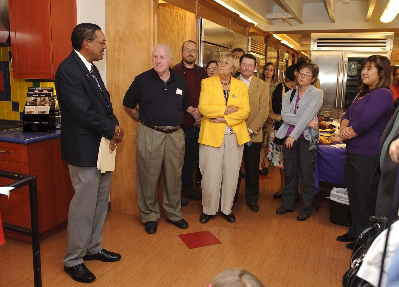
Ames 70 Year Anniversary Exhibit in downtown Mountain View, California. Grand Opening at Meyer Appliance, Castro Street. Lewis Braxton III, Ames Deputy Center Director opens exhibit.
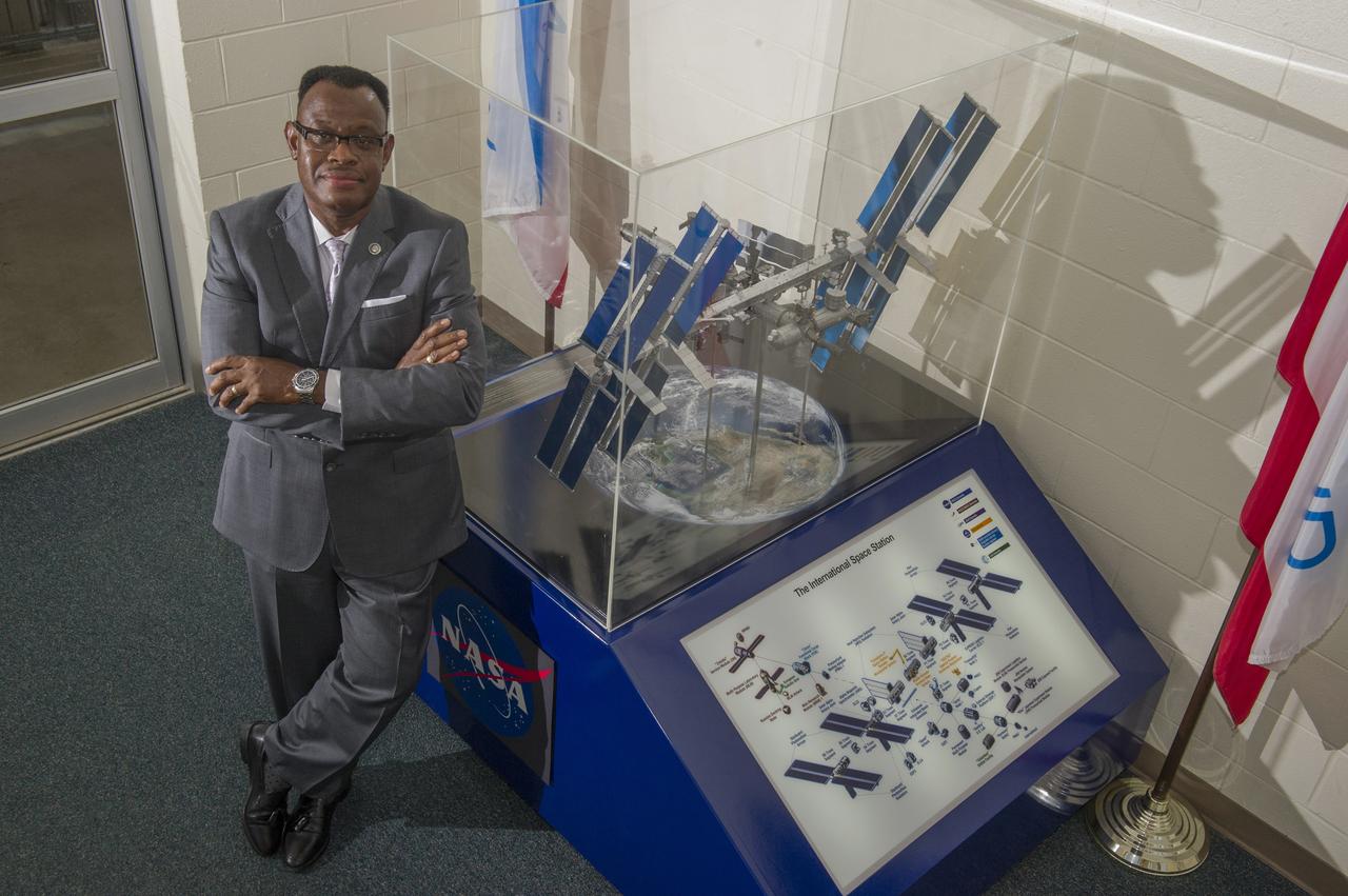
LEWIS WOOTEN MANAGES THE MISSION OPERATIONS LABORATORY. MORE THAN 1600 INVESTIGATIONS AND STUDENT EXPERIMENTS FOR OVER 80 COUNTRIES HAVE BEEN COMPLETED WITH THE HELP OF WOOTEN'S TEAM AT NASA'S MARSHALL SPACE FLIGHT CENTER IN HUNTSVILLE, ALABAMA.
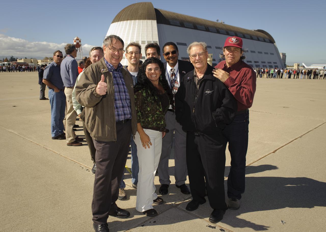
Ames 70_year picture day on Flight line. Center Director S. Pete Worden, ______, Jack Boyd, Lewis Braxton, III, Tim Naumowicz start the line on the seven.

Ames 70 Year Anniversary Exhibit in downtown Mountain View, California. Grand Opening at Meyer Appliance, Castro Street. Lewis Braxton III, Ames Deputy Center Director opens exhibit.
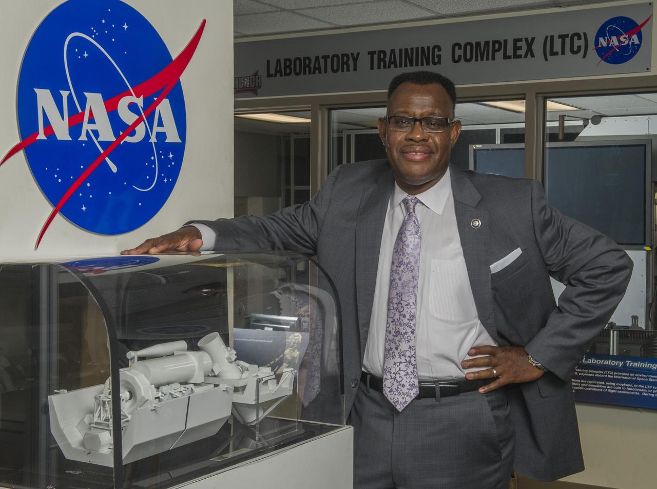
LEWIS WOOTEN MANAGES THE MISSION OPERATIONS LABORATORY. MORE THAN 1600 INVESTIGATIONS AND STUDENT EXPERIMENTS FOR OVER 80 COUNTRIES HAVE BEEN COMPLETED WITH THE HELP OF WOOTEN'S TEAM AT NASA'S MARSHALL SPACE FLIGHT CENTER IN HUNTSVILLE, ALABAMA.
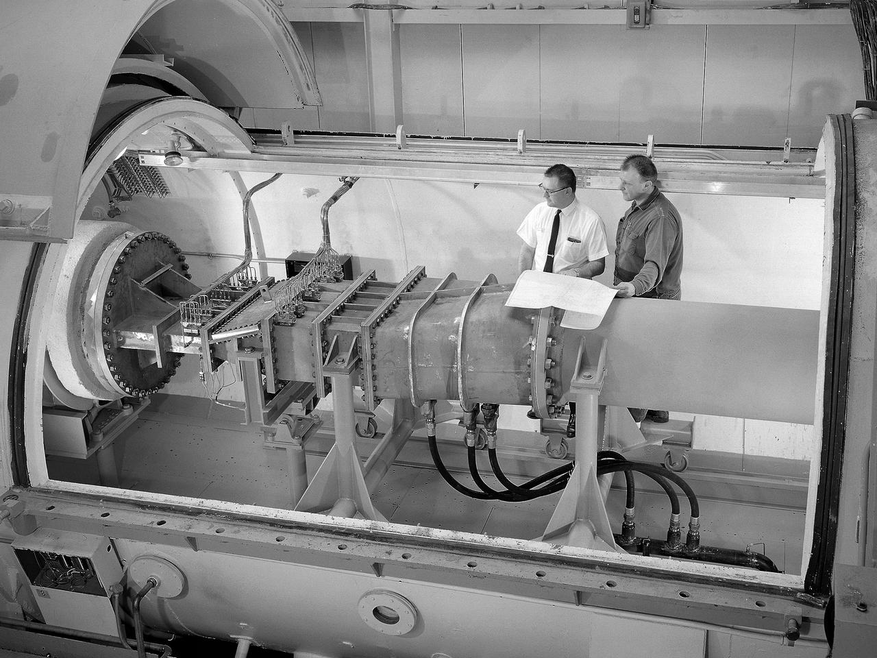
Engineer Frank Kutina and a National Aeronautics and Space Administration (NASA) mechanic examine the setup of an advanced combustor rig inside one of the test cells at the Lewis Research Center’s Four Burner Area in the Engine Research Building. Kutina, of the Research Operations Branch, served as go-between for the researchers and the mechanics. He helped develop the test configurations and get the hardware installed. At the time of this photograph, Lewis Center Director Abe Silverstein had just established the Airbreathing Engine Division to address the new propulsion of the 1960s. After nearly a decade of focusing almost exclusively on space, NASA Lewis began tackling issues relating to the new turbofan engine, noise reduction, energy efficiency, supersonic transport, and the never-ending quest for higher performance levels with smaller and more lightweight engines. The Airbreathing Engine Division’s Combustion Branch was dedicated to the study and mitigation of the high temperatures and pressures found in advanced combustor designs. These high temperatures and pressures could destroy engine components. The Lewis investigation included film cooling, diffuser flow, and jet mixing. Components were tested in smaller test cells, but a full-scale augmenting burner rig, seen here, was tested extensively in the Four Burner Area test cell.
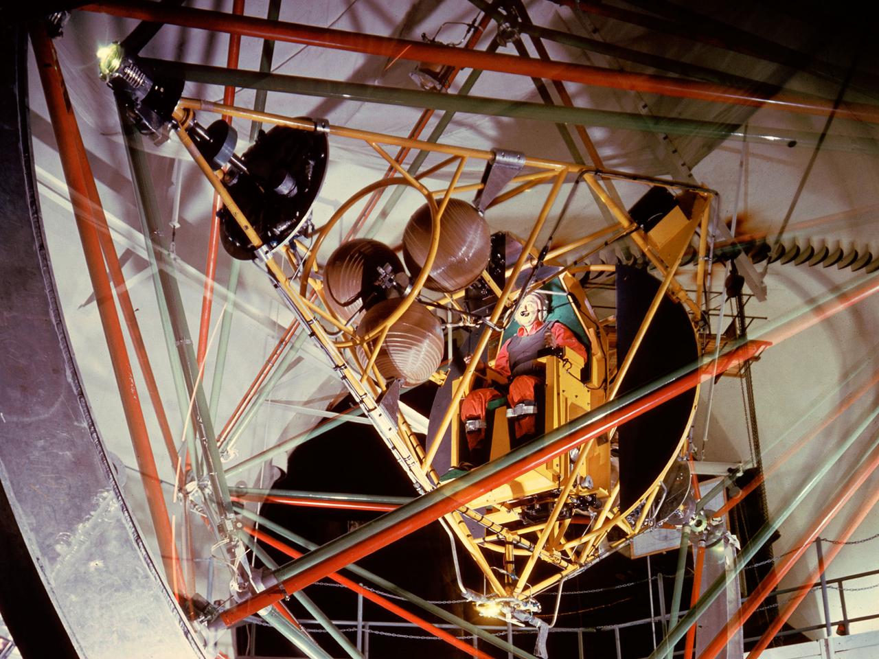
National Aeronautics and Space Administration (NASA) pilot Joe Algranti tests the Multi-Axis Space Test Inertia Facility (MASTIF) inside the Altitude Wind Tunnel while researcher Robert Miller looks on. The MASTIF was a three-axis rig with a pilot’s chair mounted in the center to train Project Mercury pilots to bring a spinning spacecraft under control. An astronaut was secured in a foam couch in the center of the rig. The rig then spun on three axes from 2 to 50 rotations per minute. Small nitrogen gas thrusters were used by the astronauts to bring the MASTIF under control. The device was originally designed in early 1959 without the chair and controllers. It was used by Lewis researchers to determine if the Lewis-designed autopilot system could rectify the capsule’s attitude following separation. If the control system failed to work properly, the heatshield would be out of place and the spacecraft would burn up during reentry. The system was flight tested during the September 1959 launch of the Lewis-assembled Big Joe capsule. The MASTIF was adapted in late 1959 for the astronaut training. NASA engineers added a pilot’s chair, a hand controller, and an instrument display to the MASTIF in order familiarize the astronauts with the sensations of an out-of-control spacecraft. NASA Lewis researcher James Useller and Algranti perfected and calibrated the MASTIF in the fall of 1959. In February and March 1960, the seven Project Mercury astronauts traveled to Cleveland to train on the MASTIF.
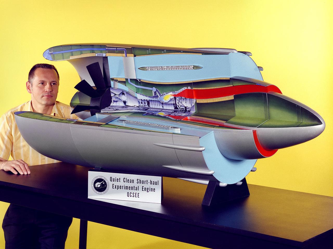
Program manager Carl Ciepluch poses with a model of the Quiet Clean Short Haul Experimental Engine (QCSEE) conceived by the National Aeronautics and Space Administration (NASA) Lewis Research Center. The QCSEE engine was designed to power future short-distance transport aircraft without generating significant levels of noise or pollution and without hindering performance. The engines were designed to be utilized on aircraft operating from small airports with short runways. Lewis researchers investigated two powered-lift designs and an array of new technologies to deal with the shorter runways. Lewis contracted General Electric to design the two QCSEE engines—one with over-the-wing power-lift and one with an under-the-wing design. A scale model of the over-the-wing engine was tested in the Full Scale Tunnel at the Langley Research Center in 1975 and 1976. Lewis researchers investigated both versions in a specially-designed test stand, the Engine Noise Test Facility, on the hangar apron. The QCSEE engines met the goals set out by the NASA researchers. The aircraft industry, however, never built the short-distance transport aircraft for which the engines were intended. Different technological elements of the engine, however, were applied to some future General Electric engines.
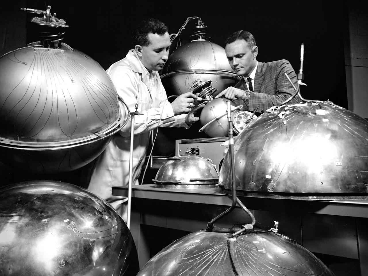
An engineer and technician at the National Aeronautics and Space Administration (NASA) Lewis Research Center install the instrumentation on spherical fuel tanks for an investigation of the behavior of liquids in microgravity. Lewis researchers were undertaking a broad effort to study the heat transfer properties of high energy propellants such as liquid hydrogen in microgravity. In the center’s 2.2-Second Drop Tower they investigated the wetting characteristics of liquid and the liquid-vapor configurations, and predicted the equilibrium state in microgravity conditions. Lewis was also conducting a series microgravity investigations which launched 9-inch diameter spherical dewars, seen here, on an Aerobee sounding rocket. A camera inside the rocket filmed the liquid hydrogen’s behavior during its 4 to 7 minutes of freefall. The researchers concluded, however, that they needed to extend the weightlessness period to obtain better results. So they designed an experiment to be launched on an Atlas missile that would provide 21 minutes of weightlessness. The experiment was flight qualified at Lewis. The 36-percent full liquid hydrogen stainless steel dewar was launched on the Atlas on February 25, 1964. The instrumentation measured temperature, pressure, vacuum, and liquid level. Temperature instrumentation indicated wall drying during the freefall. The resultant pressure-rise characteristics were similar to those used for the normal-gravity test.
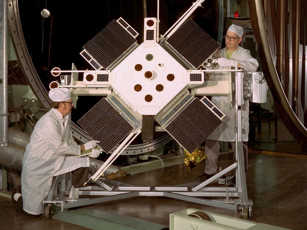
Researchers examine the Space Plasma-High Voltage Interaction Experiment (SPHINX) satellite in the Electric Propulsion Laboratory at the National Aeronautics and Space Administration (NASA) Lewis Research Center. Lewis’ Spacecraft Technology Division designed SPHINX to study the electrical interaction of its experimental surfaces with space plasma. They sought to determine if higher orbits would improve the transmission quality of communications satellites. Robert Lovell, the Project Manager, oversaw vibrational and plasma simulation testing of the satellite in the Electric Propulsion Laboratory, seen here. SPHINX was an add-on payload for the first Titan/Centaur proof launch in early 1974. Lewis successfully managed the Centaur Program since 1962, but this would be the first Centaur launch with a Titan booster. Since the proof test did not have a scheduled payload, the Lewis-designed SPHINX received a free ride. The February 11, 1974 launch, however, proved to be one of the Launch Vehicle Division’s lowest days. Twelve minutes after the vehicle departed the launch pad, the booster and Centaur separated as designed, but Centaur’s two RL-10 engines failed to ignite. The launch pad safety officer destroyed the vehicle, and SPHINX never made it into orbit. Overall Centaur has an excellent success rate, but the failed SPHINX launch attempt caused deep disappointment across the center.
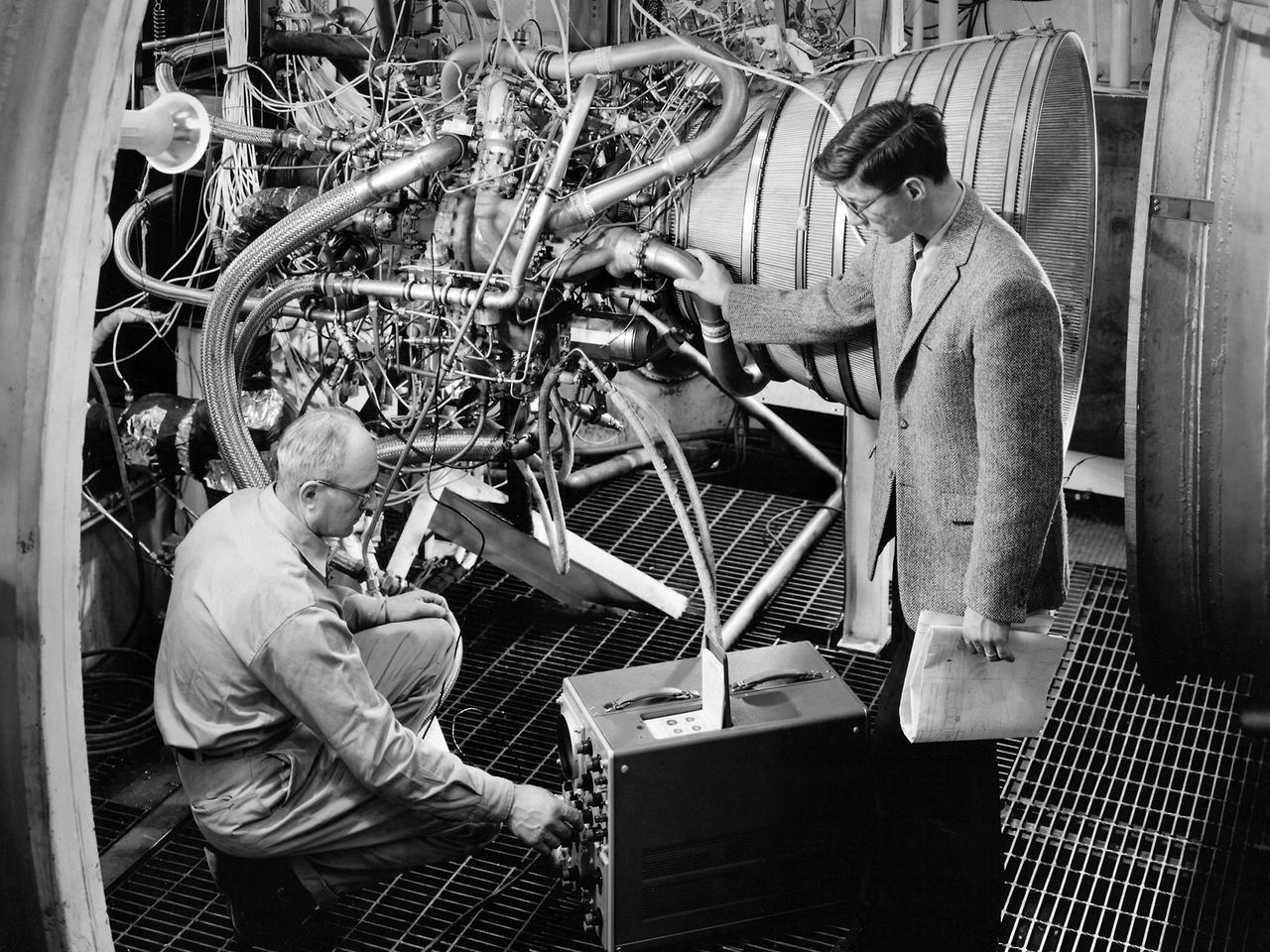
Lead Test Engineer John Kobak (right) and a technician use an oscilloscope to test the installation of a Pratt and Whitney RL-10 engine in the Propulsion Systems Laboratory at the National Aeronautics and Space Administration (NASA) Lewis Research Center. In 1955 the military asked Pratt and Whitney to develop hydrogen engines specifically for aircraft. The program was canceled in 1958, but Pratt and Whitney decided to use the experience to develop a liquid-hydrogen rocket engine, the RL-10. Two of the 15,000-pound-thrust RL-10 engines were used to power the new Centaur second-stage rocket. Centaur was designed to carry the Surveyor spacecraft on its mission to soft-land on the Moon. Pratt and Whitney ran into problems while testing the RL-10 at their facilities. NASA Headquarters assigned Lewis the responsibility for investigating the RL-10 problems because of the center’s long history of liquid-hydrogen development. Lewis’ Chemical Rocket Division began a series of tests to study the RL-10 at its Propulsion Systems Laboratory in March 1960. The facility contained two test chambers that could study powerful engines in simulated altitude conditions. The first series of RL-10 tests in early 1961 involved gimballing the engine as it fired. Lewis researchers were able to yaw and pitch the engine to simulate its behavior during a real flight.
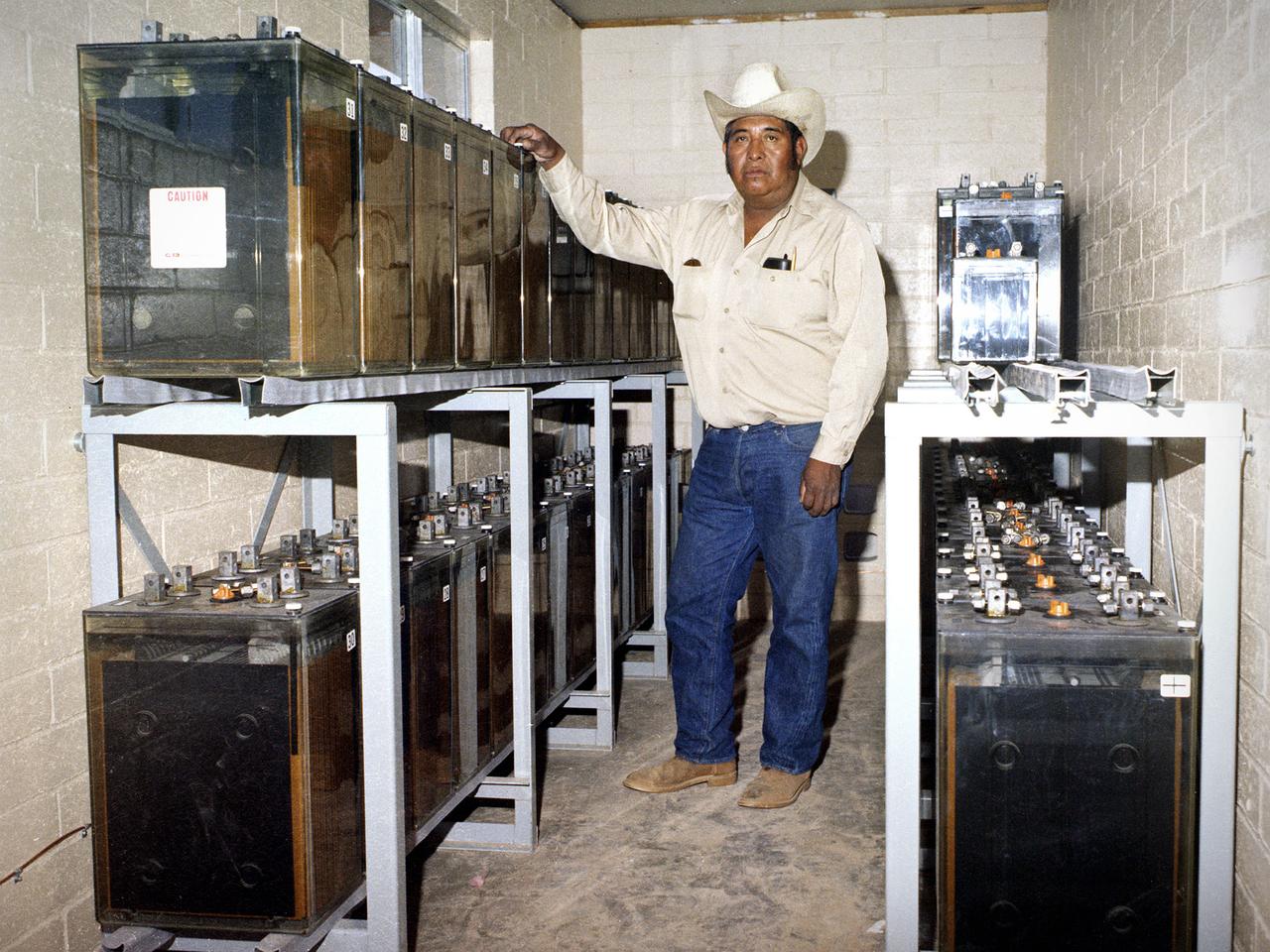
National Aeronautics and Space Administration (NASA) Lewis Research Center. NASA signed an agreement with the Papago tribe in May 1978 to provide the village with solar-generated electricity within the year. The project was funded by the Department of Energy and managed by NASA Lewis. Lewis provided all of the equipment and technical assistance while the tribe’s construction team built the arrays and support equipment, seen here. The 3.5-kilowatt system was modest in scope, but resulted in the first solar electric village. The system provided power to operate a refrigerator, freezer, washing machine, and water pump for the village and lights in each of the 16 homes. The system was activated on December 16, 1978. During the next year officials from around the world travelled to Schuchuli to ascertain if the system was applicable to their areas. The major television networks and over 100 publications covered the story. Less than one percent of the cells failed during the first year of operation.

NASA pilot Ed Lewis with the T-34C aircraft on the Dryden Flight Research Center Ramp. The aircraft was previously used at the Lewis Research Center in propulsion experiments involving turboprop engines, and was used as a chase aircraft at Dryden for smaller and slower research projects. Chase aircraft accompany research flights for photography and video purposes, and also as support for safety and research. At Dryden, the T-34 is used mainly for smaller remotely piloted vehicles which fly slower than NASA's F-18's, used for larger scale projects. This aircraft was returned to the U.S. Navy in May of 2002.
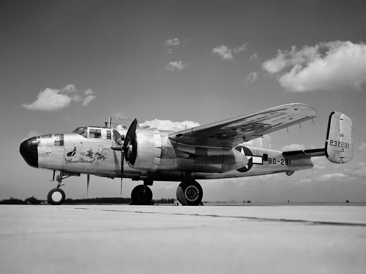
In 1946 the Lewis Flight Propulsion Laboratory became the NACA’s official icing research center. In addition to the Icing Research Tunnel, the lab possessed several aircraft modified for icing work, including a Consolidated B-24M Liberator and a North American XB-25E Mitchell, seen here. The XB-25E’s frequent engine fires allegedly resulted in its “Flamin’ Maimie” nickname. The aircraft’s nose art, visible in this photograph, includes a leather-jacketed mechanic with an extinguisher fleeing a fiery woman. North American developed the B-25 in the mid-1930s as a transport aircraft, but it was hurriedly reconfigured as a medium bomber for World War II. This XB-25E was a single prototype designed in 1942 specifically to test an exhaust gas ice prevention system developed by NACA researcher Lewis Rodert. The system circulated the engines’ hot bleed air to the wings, windshield, and tail. The XB-25E was utilized at the NACA’s Ames Aeronautical Laboratory for two years before being transferred to Cleveland in July 1944. NACA Lewis mechanics modified the aircraft further by installing electrical heating in the front fuselage, propellers, inboard sing, cowls, and antennae. Lewis pilots flew the B-24M and XB-25E into perilous weather conditions all across the country to study both deicing technologies and the physics of ice-producing clouds. These dangerous flights led to advances in weather sensing instruments and flight planning.
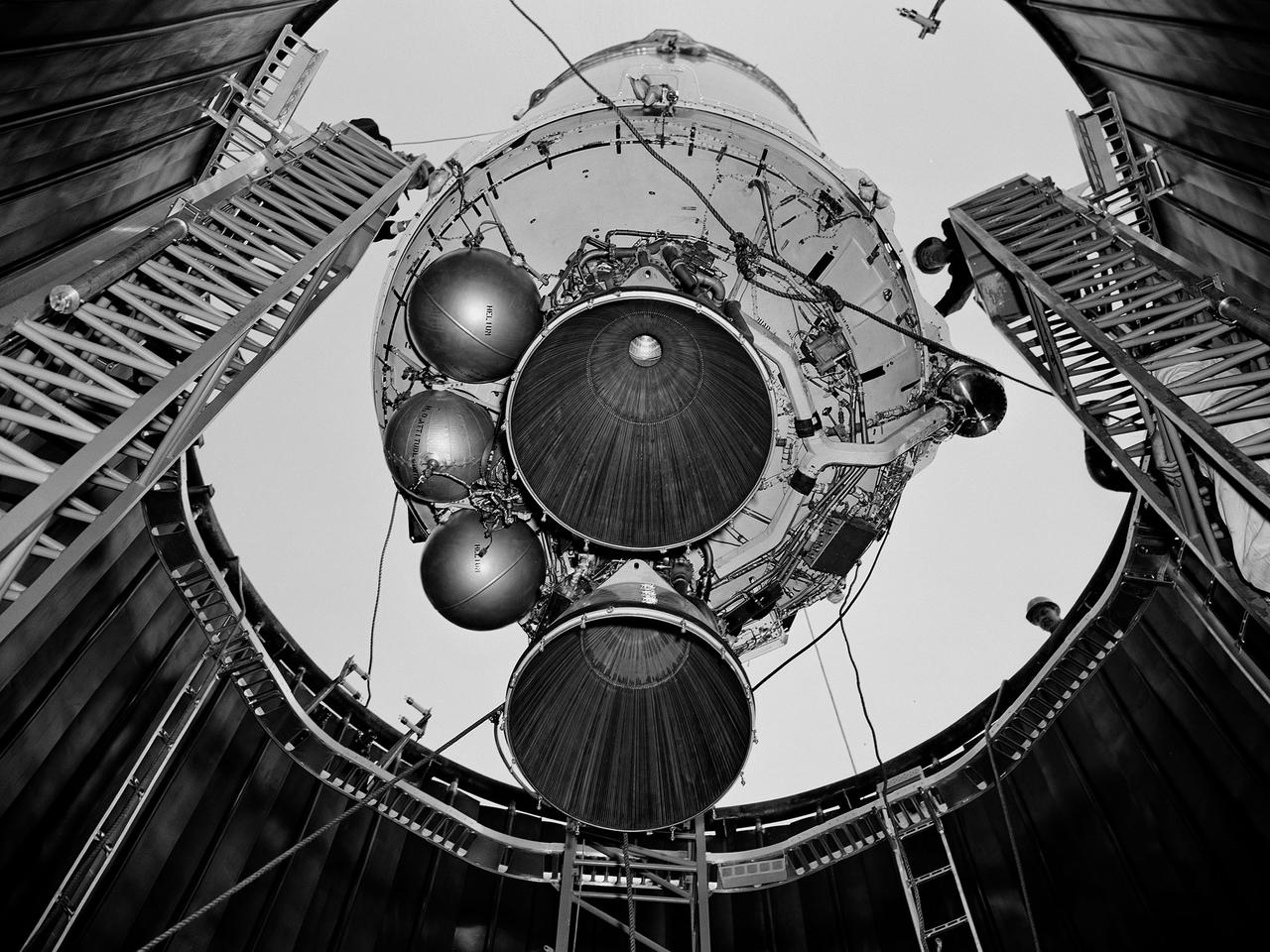
A Centaur second-stage rocket is lowered into the vacuum tank inside the Space Power Chambers at NASA’s Lewis Research Center. Centaur was to be paired with an Atlas booster to send the Surveyor spacecraft to the moon as a precursor to the Apollo landings. Lewis was assigned responsibility for the Centaur Program after the failure of its first developmental flight in May 1962. Lewis’ Altitude Wind Tunnel was converted into two large test chambers—the Space Power Chambers. The facility’s vacuum chamber, seen here, allowed the Centaur to be stood up vertically and subjected to atmospheric conditions-- pressures, temperature, and radiation--similar to those it would encounter in space. The Centaur for these tests was delivered to Cleveland in a C‒130 aircraft on September 27, 1963. The rocket was set up in the facility’s high bay where Lewis technicians and General Dynamics consultants updated its flight systems to match the upcoming Atlas-Centaur‒4 mission. Months were spent reharnessing the Centaur’s electronics, learning about the systems, and being taught how to handle flight hardware. By early spring 1964, the extensive setup of both the spacecraft and the chamber was finally completed. On March 19 the Centaur was rolled out from the shop, hoisted high into the air by a crane, and lowered into the waiting space tank. Researchers were able to verify that the Centaur’s electronics and electrical systems functioned reliably in a space environment.
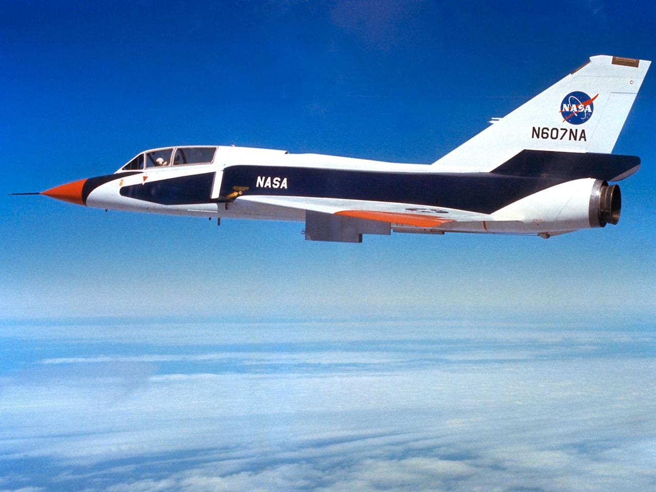
The National Aeronautics and Space Administration (NASA) Lewis Research Center’s Convair F-106B Delta Dart equipped with air sampling equipment in the mid-1970s. NASA Lewis created and managed the Global Air Sampling Program (GASP) in 1972 in partnership with several airline companies. NASA researchers used the airliners’ Boeing 747 aircraft to gather air samples to determine the amount of pollution present in the stratosphere. Private companies developed the air sampling equipment for the GASP program, and Lewis created a particle collector. The collector was flight tested on NASA Lewis’ F-106B in the summer of 1973. The sampling equipment was automatically operated once the proper altitude was achieved. The sampling instruments collected dust particles in the air so their chemical composition could be analyzed. The equipment analyzed one second’s worth of data at a time. The researchers also monitored carbon monoxide, monozide, ozone, and water vapor. The 747 flights began in December 1974 and soon included four airlines flying routes all over the globe. The F-106B augmented the airline data with sampling of its own, seen here. It gathered samples throughout this period from locations such as New Mexico, Texas, Michigan, and Ohio. In July 1977 the F-106B flew eight GASP flights in nine days over Alaska to supplement the earlier data gathered by the airlines.
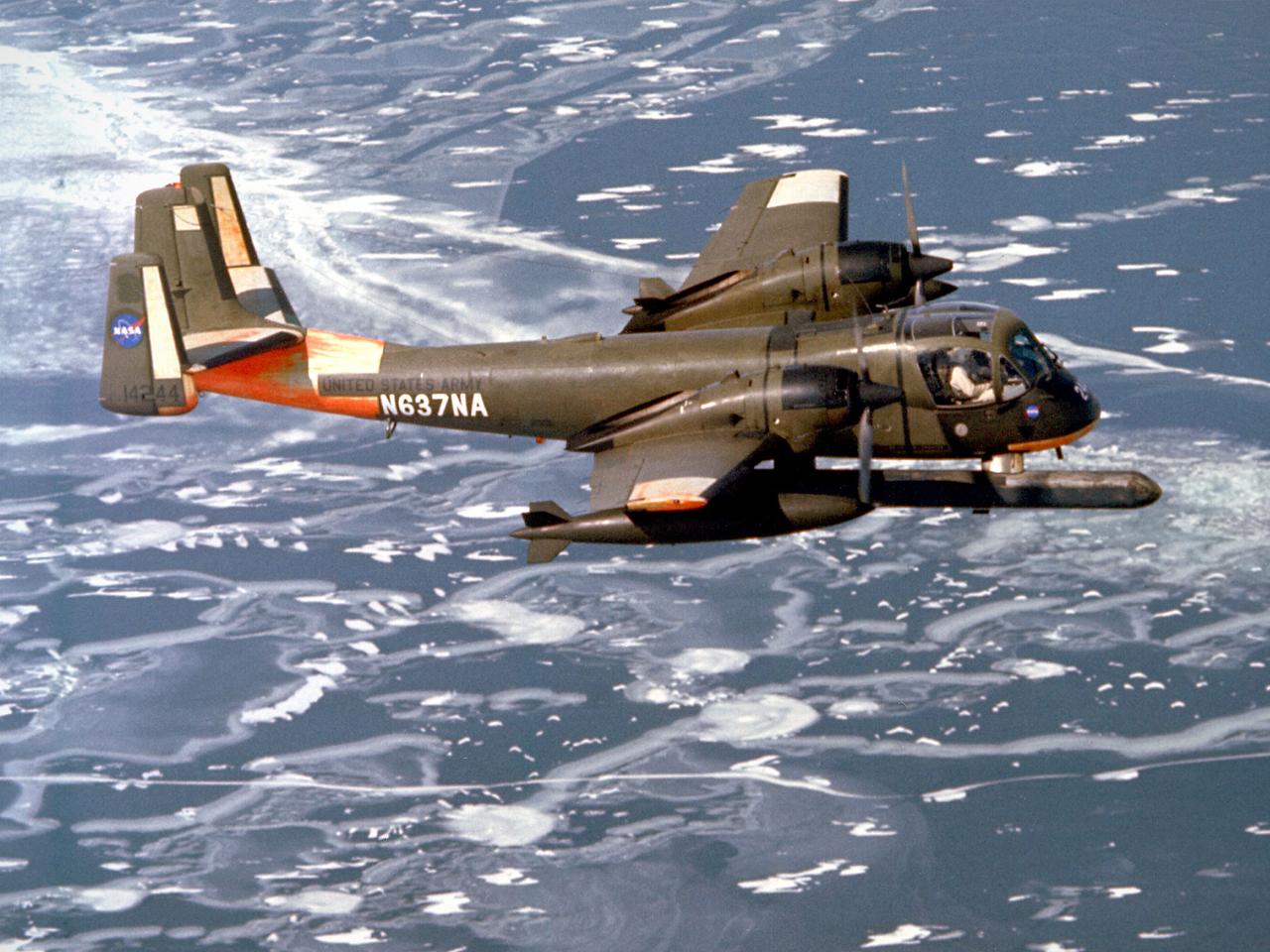
A Grumman OV-1B Mohawk maps Great Lakes’ ice flows for the National Aeronautics and Space Administration (NASA) Lewis Research Center in Cleveland, Ohio. The regular freezing of large portions of the Great Lakes during the winter frequently stalled the region’s shipping industry. Lewis developed two complementary systems to monitor the ice. The Side Looking Airborne Radar (SLAR) system used microwaves to measure the ice distribution, and electromagnetic systems employed noise modulation to determine the thickness of the ice. Once this dual system was in place, the information could be generated during a single pass of a research aircraft and quickly distributed to ship captains planning their routes. The SLAR was superior to aerial photography for this task because it was able to penetrate cloud cover. The SLAR system used pulsed microwaves to examine a band of ice or water on either side of the aircraft up to 31 miles wide. The Lewis ice mapping devices were first tested during the winter of 1972 and 1973. The system was installed on the tail of the Coast Guard’s OV-1B aircraft. An infrared thermal mapping instrument was installed on Lewis’ DC-3 to determine the ice temperature and estimate its thickness. The team created 160 ice charts that were sent to 28 ships and 2 icebreakers. Shipping was able to continue throughout the season for the first time that winter.
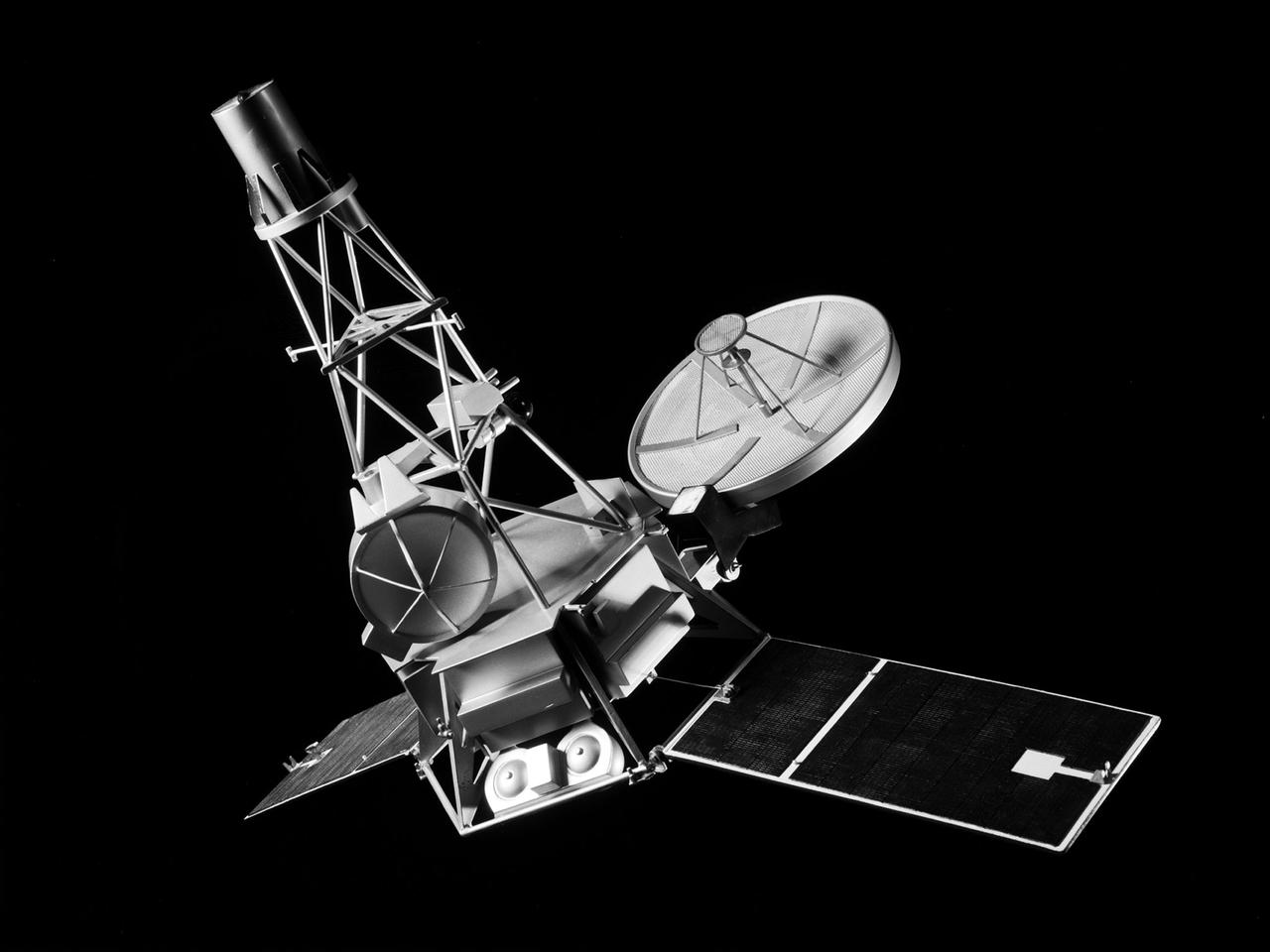
A model of the Mariner-C spacecraft at the National Aeronautics and Space Administration (NASA) Lewis Research Center for a June 1964 Conference on New Technology. Mariner-C and Mariner-D were identical spacecraft designed by the Jet Propulsion Laboratory to flyby Mars and photograph the Martian surface. Mariner-C was launched on November 4, 1964, but the payload shroud did not jettison properly and the spacecraft’s battery power did not function. The mission ended unsuccessfully two days later. Mariner-D was launched as designed on November 28, 1964 and became the first successful mission to Mars. It was the first time a planet was photographed from space. Mariner-D’s 21 photographs revealed an inhospitable and barren landscape. The two Mariner spacecraft were launched by Atlas-Agena-D rockets. Lewis had taken over management of the Agena Program in October 1962. There had been five failures and two partial failures in the 17 Agena launches before being taken over by NASA Lewis. Lewis, however, oversaw 28 successful Agena missions between 1962 and 1968, including several Rangers and the Mariner Venus '67.
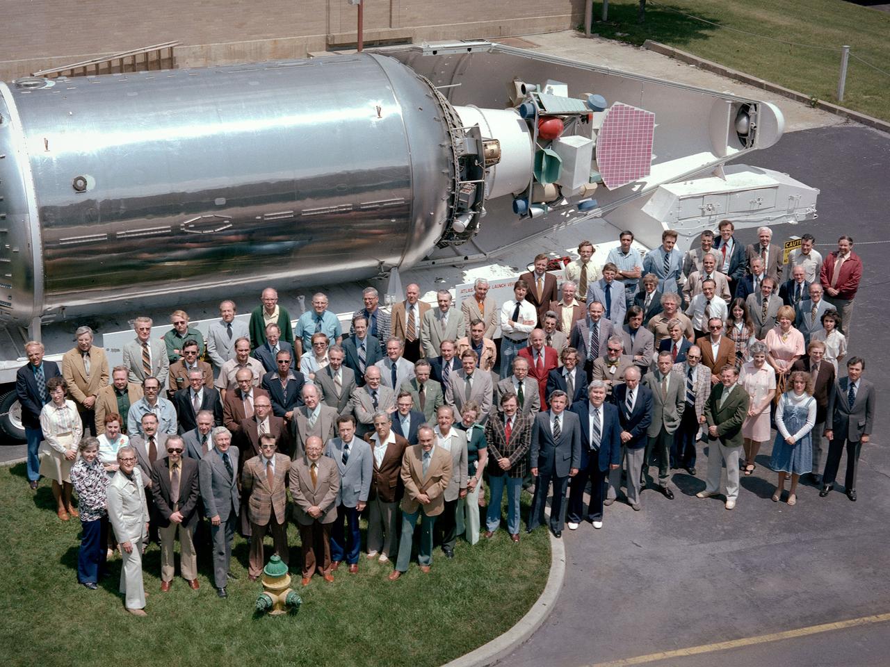
The National Aeronautics and Space Administration (NASA) Lewis Research Center’s Launch Vehicle Directorate in front of a full-scale model of the Centaur second-stage rocket. The photograph was taken to mark Centaur’s fiftieth launch. NASA Lewis managed the Centaur Program since 1962. At that time, the only prior launch attempt ended in failure. Lewis improved the spacecraft and tested it extensively throughout the early 1960s. In May 1966 an Atlas-Centaur sent the Surveyor spacecraft to the moon. It was the first successful soft landing on another planet. The Launch Vehicles Division was formed in 1969 to handle the increasing number of Centaur launches. The Lewis team became experts at integrating the payload with the Centaur and calculating proper trajectories for the missions. Centaur’s first 50 missions included Orbiting Astronomical Observatories, the Mariner 6 and 7 flybys of Mars, Mariner 9 which was the first spacecraft to orbit around another planet, the Pioneer 10 and 11 missions to the outer solar system, the Mariner 10 flyby of Venus and Mercury, the Viking 1 and 2 Mars landers, Voyagers 1 and 2 missions to Jupiter, Saturn, Uranus, and Neptune, and the Pioneer 12 and 13 flights to Venus.

National Aeronautics and Space Administration (NASA) engineer Robert Jeracki prepares a Hamilton Standard SR-1 turboprop model in the test section of the 8- by 6-Foot Supersonic Wind Tunnel at the Lewis Research Center. Lewis researchers were analyzing a series of eight-bladed propellers in their wind tunnels to determine their operating characteristics at speeds up to Mach 0.8. The program, which became the Advanced Turboprop, was part of a NASA-wide Aircraft Energy Efficiency Program which was designed to reduce aircraft fuel costs by 50 percent. The ATP concept was different from the turboprops in use in the 1950s. The modern versions had at least eight blades and were swept back for better performance. After Lewis researchers developed the advanced turboprop theory and established its potential performance capabilities, they commenced an almost decade-long partnership with Hamilton Standard to develop, verify, and improve the concept. A series of 24-inch scale models of the SR-1 with different blade shapes and angles were tested in Lewis’ wind tunnels. A formal program was established in 1978 to examine associated noise levels, aerodynamics, and the drive system. The testing of the large-scale propfan was done on test rigs, in large wind tunnels, and, eventually, on aircraft.
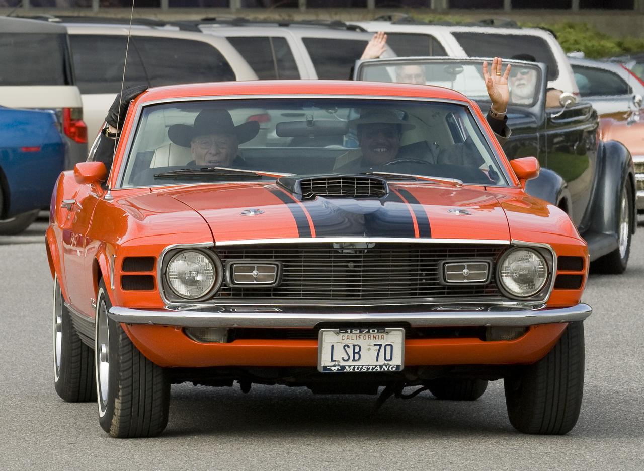
Ames 70th Anniversary Turn Back the Clock Day with antique Class Cars and Classic Car parade around the center. Lewis Braxton III, Ames Deputy Center Director and Jack Boyd, Ames Historian lead the parade in Lew's Mustang.
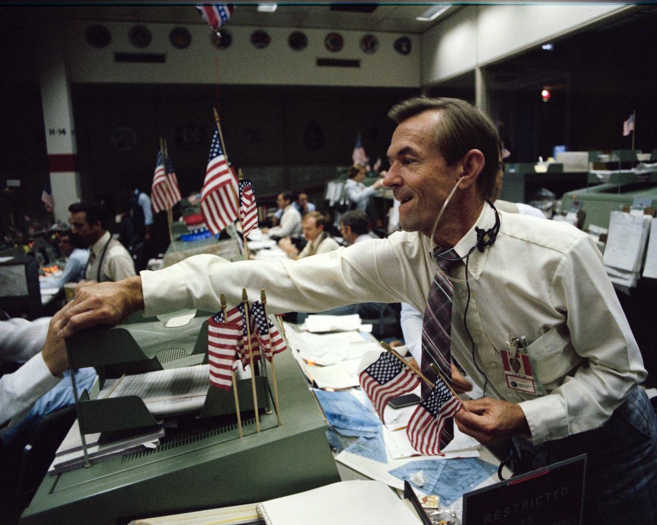
S82-33221 (4 July 1982) --- Lead STS-4 flight director Charles Lewis is congratulated by an unidentified flight controller (partially out of frame) in the Johnson Space Center's Mission Control Center following the landing of the space shuttle Columbia at Edwards Air Force Base in California. Photo credit: NASA
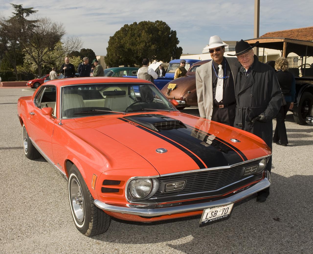
Ames 70th Anniversary Turn Back the Clock Day with antique Class Cars and Classic Car parade around the center. Lewis Braxton III, Ames Deputy Center Director and Jack Boyd, Ames Historian pose by Lew's Mustang before leading the parade.
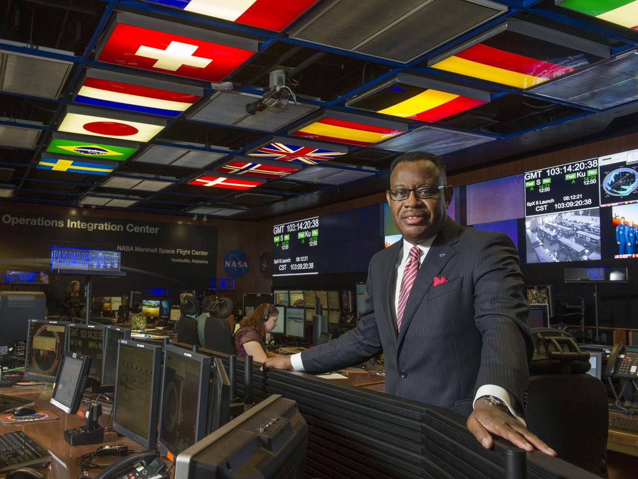
LEWIS WOOTEN, NEW DIRECTOR OF THE MISSION OPERATIONS LABORATORY AT NASA'S MARSHALL SPACE FLIGHT CENTER IN HUNTSVILLE, ALABAMA, MANAGES OPERATIONS IN THE PAYLOAD OPERATIONS INTEGRATION CENTER-THE COMMAND POST FOR ALL SCIENCE AND RESEARCH ACTIVITIES ON THE INTERNATIONAL SPACE STATION